KR20170099685A - Module for heating and cooling cup using Peltier thermoelectric element - Google Patents
Module for heating and cooling cup using Peltier thermoelectric elementDownload PDFInfo
- Publication number
- KR20170099685A KR20170099685AKR1020160022068AKR20160022068AKR20170099685AKR 20170099685 AKR20170099685 AKR 20170099685AKR 1020160022068 AKR1020160022068 AKR 1020160022068AKR 20160022068 AKR20160022068 AKR 20160022068AKR 20170099685 AKR20170099685 AKR 20170099685A
- Authority
- KR
- South Korea
- Prior art keywords
- thermoelectric element
- cup
- case
- present
- peltier
- Prior art date
- Legal status (The legal status is an assumption and is not a legal conclusion. Google has not performed a legal analysis and makes no representation as to the accuracy of the status listed.)
- Abandoned
Links
- 238000001816coolingMethods0.000titleabstractdescription12
- 238000010438heat treatmentMethods0.000titledescription7
- 238000010792warmingMethods0.000abstractdescription2
- 230000000694effectsEffects0.000description7
- 238000010168coupling processMethods0.000description3
- 239000003507refrigerantSubstances0.000description3
- 230000005679Peltier effectEffects0.000description2
- 238000003780insertionMethods0.000description2
- 230000037431insertionEffects0.000description2
- 238000009434installationMethods0.000description2
- 239000000463materialSubstances0.000description2
- 229910052751metalInorganic materials0.000description2
- 239000002184metalSubstances0.000description2
- 150000002739metalsChemical class0.000description2
- 239000004065semiconductorSubstances0.000description2
- 238000006243chemical reactionMethods0.000description1
- 230000005494condensationEffects0.000description1
- 238000009833condensationMethods0.000description1
- 238000011109contaminationMethods0.000description1
- 230000008878couplingEffects0.000description1
- 238000005859coupling reactionMethods0.000description1
- 230000006378damageEffects0.000description1
- 230000007613environmental effectEffects0.000description1
- 230000001151other effectEffects0.000description1
- 238000013021overheatingMethods0.000description1
- 238000005057refrigerationMethods0.000description1
- 230000000630rising effectEffects0.000description1
- 230000014860sensory perception of tasteEffects0.000description1
- 239000000126substanceSubstances0.000description1
Images


Classifications
- A—HUMAN NECESSITIES
- A47—FURNITURE; DOMESTIC ARTICLES OR APPLIANCES; COFFEE MILLS; SPICE MILLS; SUCTION CLEANERS IN GENERAL
- A47G—HOUSEHOLD OR TABLE EQUIPMENT
- A47G19/00—Table service
- A47G19/22—Drinking vessels or saucers used for table service
- A47G19/2288—Drinking vessels or saucers used for table service with means for keeping liquid cool or hot
- A—HUMAN NECESSITIES
- A47—FURNITURE; DOMESTIC ARTICLES OR APPLIANCES; COFFEE MILLS; SPICE MILLS; SUCTION CLEANERS IN GENERAL
- A47G—HOUSEHOLD OR TABLE EQUIPMENT
- A47G23/00—Other table equipment
- A47G23/02—Glass or bottle holders
- A47G23/0208—Glass or bottle holders for drinking-glasses, plastic cups, or the like
- A—HUMAN NECESSITIES
- A47—FURNITURE; DOMESTIC ARTICLES OR APPLIANCES; COFFEE MILLS; SPICE MILLS; SUCTION CLEANERS IN GENERAL
- A47G—HOUSEHOLD OR TABLE EQUIPMENT
- A47G23/00—Other table equipment
- A47G23/03—Underlays for glasses or drinking-vessels
- A47G23/0313—Underlays for glasses or drinking-vessels with means for keeping food cool or hot
- A—HUMAN NECESSITIES
- A47—FURNITURE; DOMESTIC ARTICLES OR APPLIANCES; COFFEE MILLS; SPICE MILLS; SUCTION CLEANERS IN GENERAL
- A47J—KITCHEN EQUIPMENT; COFFEE MILLS; SPICE MILLS; APPARATUS FOR MAKING BEVERAGES
- A47J36/00—Parts, details or accessories of cooking-vessels
- A47J36/24—Warming devices
- A—HUMAN NECESSITIES
- A47—FURNITURE; DOMESTIC ARTICLES OR APPLIANCES; COFFEE MILLS; SPICE MILLS; SUCTION CLEANERS IN GENERAL
- A47J—KITCHEN EQUIPMENT; COFFEE MILLS; SPICE MILLS; APPARATUS FOR MAKING BEVERAGES
- A47J36/00—Parts, details or accessories of cooking-vessels
- A47J36/24—Warming devices
- A47J36/2444—Drinking cups with heating means
- H01L35/30—
Landscapes
- Engineering & Computer Science (AREA)
- Food Science & Technology (AREA)
- Physics & Mathematics (AREA)
- Thermal Sciences (AREA)
- Devices That Are Associated With Refrigeration Equipment (AREA)
Abstract
Translated fromKorean
Description
Translated fromKorean본 발명은 보온/보냉 장치에 관한 것으로서, 보다 상세하게는 콤팩트한 구성이 가능하며 사용이 편리하도록 구성된 펠티어 열전소자를 사용하는 컵 보온/보냉 장치에 관한 것이다.BACKGROUND OF THE INVENTION 1. Field of the Invention The present invention relates to a warm / cold device, and more particularly, to a cup warm / cold device using a Peltier thermoelectric device that is compact and can be easily used.
최근 종류가 다른 두 금속으로 구성된 소자(素子)에 직류 전원이 인가되면 양쪽 표면 사이에 열적 기울기가 형성 즉, 한 쪽 표면은 고온, 다른 쪽 표면은 저온을 띠게 되는 특성(펠티어 효과; Peltier effect)을 갖는 소위 열전 반도체 또는 열전소자(熱電素子, 일명, "펠티어소자" 라고도 한다)를 이용하여 저온 또는 고온 상태를 구현할 수 있는 냉온 장치가 구비된 제품들이 연구 개발되어 개시되고 있다.Recently, when DC power is applied to an element composed of two different kinds of metals, a thermal gradient is formed between both surfaces, that is, a high temperature on one side and a low temperature on the other side (Peltier effect) (Thermoelectric element, also referred to as "Peltier element") having a thermoelectric element or a thermoelectric element having a thermoelectric element or a thermoelectric element,
즉, 상기 열전소자는 2종의 서로 다른 금속을 결합시키거나 또는 n형 반도체와 p형 반도체를 상호 접합시켜서 이루어진 소자로써, 이 열전소자에 직류 전류를 가하면 양 금속표면에서 흡열반응과 방열반응이 일어나는 특성을 가지게 된다.That is, the thermoelectric element is an element formed by bonding two different metals or bonding an n-type semiconductor and a p-type semiconductor to each other. When a direct current is applied to the thermoelectric element, an endothermic reaction and a heat- It has the characteristic of rising.
여기서, 상기 열전소자(펠티어소자)에 대해서 좀 더 부연 설명하면, 열전소자는 펠티어 효과(전극의 양단에 온도차가 발생하면 에너지 준위의 변화로 전극을 통해 전류가 흐른다)를 이용하여 만들어진 소자로서, 흐르는 전류양에 따라서 양극간에 온도차를 발생시키는 소자이다. 이에 기준면을 세팅시키면(원하는 기준온도에 기준면을 부착시킨다)전류의 방향과 양에 따라 ㅁ△QC의 열량차가 양극(면) 사이에 발생하여 한편은 열을 빼앗고 반대편은 열을 발생하게 된다.Here, the thermoelectric element (Peltier element) will be described in more detail. The thermoelectric element is made by using a Peltier effect (a current flows through the electrode due to a change in energy level when a temperature difference occurs between both ends of the electrode) And generates a temperature difference between the positive and negative electrodes according to the amount of current flowing. If the reference plane is set (the reference plane is attached to the desired reference temperature), the difference in the heat quantity of △ QC occurs between the positive electrode (plane) according to the direction and the amount of current, and the heat is taken away and the other side generates heat.
따라서, 열전소자의 흡열부위에 열교환기를 설치하게 되면 주위공간을 냉각시킬 수 있으며, 반대로 방열부위에 열교환기를 설치하게 되면 주위공간의 온도를 상승시킬 수 있는 것이다.Accordingly, if the heat exchanger is installed in the heat absorbing portion of the thermoelectric element, the surrounding space can be cooled. On the contrary, if the heat exchanger is installed in the heat dissipating portion, the temperature of the surrounding space can be increased.
이 열전소자(펠티어소자)를 이용한 냉각방식의 특징은 기존의 냉동사이클에서 이용하는 프레온 등과 같은 냉매 가스를 사용하지 않고서도 주위를 냉각시킬 수 있게 되어 프레온과 같은 냉매가스 등의 누출에 따른 환경파괴를 발생시키지 않을 뿐만 아니라, 냉매가스를 압축하기 위한 압축기와 같은 구동장치가 필요 없게 되어 작동 소음이 발생하지 않게 된다.The characteristic of the cooling method using this thermoelectric element (Peltier element) is that it is possible to cool the surroundings without using refrigerant gas such as Freon used in the conventional refrigeration cycle, and thereby to prevent the environmental destruction due to leakage of refrigerant gas such as Freon So that a driving device such as a compressor for compressing the refrigerant gas is not required, and operation noise is not generated.
또한, 일반적으로 열전소자의 크기가 작기 때문에 설치하기가 매우 용이하며, 제품을 콤팩트하게 구성할 수 있다는 특징이 있다.In addition, since the size of the thermoelectric element is generally small, it is very easy to install and the product can be compactly constructed.
따라서, 이러한 열전소자(펠티어소자)를 이용하여 소형 냉장고를 비롯한 각종 냉온 장치를 구현할 수 있는 제품들이 개발되고 있다.Therefore, products capable of implementing various cold / warm devices including a small refrigerator using such thermoelectric elements (Peltier elements) are being developed.
본 발명은 상술한 종래의 문제점 및 제결점을 해결하기 위하여 안출된 것으로서, 본 발명은 구조가 간단하여 소형화가 가능하고 적은 에너지를 소모하여 큰 냉각 또는 보온 효과를 얻을 수 있는 컵 보온/보냉모듈을 제공하는데 그 목적이 있다.Disclosure of the Invention The present invention has been conceived to solve the above-mentioned problems and disadvantages of the related art, and it is an object of the present invention to provide a cup keeping / inserting module which can be miniaturized and consumes less energy, The purpose is to provide.
또한 본 발명은 냉각 또는 보온 효과를 장시간 지속시킬 수 있도록 하는 컵 보온/보냉모듈을 제공하는데 그 목적이 있다.It is another object of the present invention to provide a cup keeping / inserting module capable of maintaining a cooling or keeping effect for a long time.
본 발명의 과제들은 이상에서 언급한 과제들로 제한되지 않으며, 언급되지 않은 또 다른 과제들은 아래의 기재로부터 당업자에게 명확하게 이해될 수 있을 것이다.The problems of the present invention are not limited to the above-mentioned problems, and other problems not mentioned can be clearly understood by those skilled in the art from the following description.
상기한 목적을 달성하기 위한 본 발명에 따른 펠티어 열전소자를 사용하는 컵 보온/보냉 장치는, 상부가 개구되며 내부 수용부가 구비된 케이스, 상기 케이스 상부 개구부를 폐쇄하며 중앙부에 안착부가 구비된 커버부, 상기 안착부에 설치되는 열전소자, 상기 케이스 내부 수용부에 구비되는 회전팬부, 상기 케이스 내부 수용부에 구비되며 상기 회전팬부를 작동시키는 작동모터부 및 상기 열전소자와 전기적으로 연결되는 컨트롤러부를 포함한다.According to another aspect of the present invention, there is provided a cup inserting / inserting apparatus using a Peltier thermoelectric element, comprising: a case having an upper opening and an inner accommodating portion; a cover closing the upper opening of the case, A thermoelectric element provided in the seating portion, a rotary pan provided in the case accommodating portion, an operation motor portion provided in the case accommodating portion and operating the rotary fan portion, and a controller portion electrically connected to the thermoelectric element do.
그리고 상기 커버부는, 상기 열전소자를 은폐시킬 수 있도록 상기 열전소자의 외부 둘레를 따라서 상하로 길이변형이 가능하게 설치되는 주름관부를 더 포함할 수 있다.The cover unit may further include a corrugated pipe portion that is vertically deformable along the outer circumference of the thermoelectric element so as to conceal the thermoelectric element.
또한 상기 주름관부 상부를 개폐하는 주름관커버부가 더 구비될 수 있다.Further, a corrugated pipe cover part for opening and closing the upper part of the corrugated tube part may be further provided.
그리고 상기 커버부 상부에 설치되어 상기 열전소자의 열을 상부로 전달하며, 컵의 하부 형상에 대응되도록 형성되어 상기 컵이 안착되는 홈부가 적어도 한 개 이상 형성된 받침부를 더 포함할 수 있다.And a support portion provided on the upper portion of the cover to transmit the heat of the thermoelectric element to the upper portion and to correspond to the lower shape of the cup and having at least one groove portion on which the cup is seated.
상기와 같이 구성된 본 발명의 일 실시예에 따른 펠티어 열전소자를 사용하는 컵 보온/보냉 장치의 효과에 대하여 설명하면 다음과 같다.The effect of the cup keeping / inserting apparatus using the Peltier thermoelectric device according to one embodiment of the present invention will be described as follows.
첫째, 열전소자를 사용하여 소모되는 에너지에 비하여 큰 냉각 또는 보온 효과를 얻을 수 있으므로, 그 효율성이 매우 뛰어나다는 장점이 있다.First, since the cooling or heating effect can be obtained as compared with the energy consumed by using the thermoelectric element, the efficiency is very excellent.
둘째, 소형화가 가능하여 설치 자유도가 뛰어남은 물론, 구조가 간단하여 고장을 최소화시킬 수 있는 장점이 있다.Second, miniaturization is possible, so that the degree of freedom of installation is excellent, and the structure is simple, so that the failure can be minimized.
셋째, 냉각 또는 보온 효과를 장시간 유지/지속시킬 수 있는 장점이 있다.Third, there is an advantage that the cooling or keeping effect can be maintained / maintained for a long time.
넷째, 컵이 기울어지지 않도록 안정적으로 고정시킬 수 있는 장점이 있다.Fourth, there is an advantage that the cup can be stably fixed so as not to be tilted.
다섯째, 소모되는 에너지가 적어 배터리로 구동이 가능하며, 이에 따라 휴대성이 매우 뛰어나 장소에 구애되지 않고 사용 가능하다는 장점이 있다.Fifth, since it consumes less energy, it can be driven by a battery. Therefore, it is very portable and can be used regardless of a place.
본 발명의 효과들은 이상에서 언급한 효과들로 제한되지 않으며, 언급되지 않은 또 다른 효과들은 청구범위의 기재로부터 당업자에게 명확하게 이해될 수 있을 것이다.The effects of the present invention are not limited to the effects mentioned above, and other effects not mentioned can be clearly understood by those skilled in the art from the description of the claims.
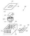
도 1은 본 발명의 제1실시예에 따른 펠티어 열전소자를 사용하는 컵 보온/보냉 장치의 각 구성요소를 분해하여 나타낸 도면;
도 2는 본 발명의 제1실시예에 따른 펠티어 열전소자를 사용하는 컵 보온/보냉 장치의 각 구성요소가 결합된 모습을 나타낸 도면;
도 3은 본 발명의 제1실시예에 따른 펠티어 열전소자를 사용하는 컵 보온/보냉 장치의 단면을 나타낸 도면;
도 4는 본 발명의 제2실시예에 따른 펠티어 열전소자를 사용하는 컵 보온/보냉 장치의 모습을 나타낸 도면;
도 5는 본 발명의 제2실시예에 따른 펠티어 열전소자를 사용하는 컵 보온/보냉 장치에 있어서, 주름관부의 길이가 변형되는 모습을 나타낸 도면;
도 6은 본 발명의 제3실시예에 따른 펠티어 열전소자를 사용하는 컵 보온/보냉 장치의 모습을 나타낸 도면; 및
도 7은 본 발명의 제2실시예에 따른 펠티어 열전소자를 사용하는 컵 보온/보냉 장치에 있어서, 받침부에 컵이 안착된 모습을 나타낸 도면이다.BRIEF DESCRIPTION OF THE DRAWINGS FIG. 1 is an exploded view of each component of a cup warm / cold apparatus using a Peltier thermoelectric device according to a first embodiment of the present invention; FIG.
FIG. 2 is a view showing a combined state of components of a cup warm / cold apparatus using a Peltier thermoelectric device according to a first embodiment of the present invention; FIG.
3 is a cross-sectional view of a cup warm / cold apparatus using a Peltier thermoelectric device according to a first embodiment of the present invention;
4 is a view showing a cup warm / cold apparatus using a Peltier thermoelectric device according to a second embodiment of the present invention;
FIG. 5 is a view showing a state in which the length of a corrugated pipe portion is deformed in a cup warm / cold storage apparatus using a Peltier thermoelectric device according to a second embodiment of the present invention; FIG.
6 is a view showing a cup warming / cooling apparatus using a Peltier thermoelectric device according to a third embodiment of the present invention; And
FIG. 7 is a view showing a state in which a cup is seated on a receiving part in a cup warm / cold storage device using a Peltier thermoelectric device according to a second embodiment of the present invention.
이하 본 발명의 목적이 구체적으로 실현될 수 있는 본 발명의 바람직한 실시예를 첨부된 도면을 참조하여 설명한다. 본 실시예를 설명함에 있어서, 동일 구성에 대해서는 동일 명칭 및 동일 부호가 사용되며 이에 따른 부가적인 설명은 생략하기로 한다. 먼저, 첨부된 도면을 참고하여 본 발명의 바람직한 실시예에 따른 구성 및 작용을 설명하기로 한다.DETAILED DESCRIPTION OF THE PREFERRED EMBODIMENTS Hereinafter, preferred embodiments of the present invention will be described with reference to the accompanying drawings. In describing the present embodiment, the same designations and the same reference numerals are used for the same components, and further description thereof will be omitted. First, the configuration and operation according to the preferred embodiment of the present invention will be described with reference to the accompanying drawings.
도 1은 본 발명의 제1실시예에 따른 펠티어 열전소자를 사용하는 컵 보온/보냉 장치(100)의 각 구성요소를 분해하여 나타낸 도면이며, 도 2는 본 발명의 제1실시예에 따른 펠티어 열전소자를 사용하는 컵 보온/보냉 장치(100)의 각 구성요소가 결합된 모습을 나타낸 도면이다.1 is an exploded view showing each component of a cup warm /
도 1 및 도 2에 도시된 바와 같이, 본 발명에 따른 펠티어 열전소자를 사용하는 컵 보온/보냉 장치(100)는, 케이스(150)와, 커버부(110)와, 열전소자(120)와, 회전팬부(130)과, 작동모터부(140)와, 컨트롤러부(200)를 포함한다.1 and 2, a cup warm /
상기 케이스(150)는 상부가 개구된 형태를 가지며, 내측에는 내부 수용부(155)가 형성된다. 상기 내부 수용부(155)에는 상기 회전팬부(130)와 상기 작동모터부(140)가 수용될 수 있다.The
본 실시예에서 상기 케이스(150)는 횡단면이 사각형 형상으로 형성되어 전체적으로 상부가 개구된 육면체 형상을 가지며, 측면에는 복수 개의 배출홀(152)이 형성된다. 또한 측면 중 하나에는, 후술할 컨트롤러부(200)의 전기적 연결라인이 통과하는 통과홀(157)이 형성된다. 다만, 상기 케이스(150)는 본 실시예의 형태로 제한되는 것이 아님은 물론이다.In the present embodiment, the
상기 커버부(110)는 상기 케이스(150)의 상부 개구부를 폐쇄하도록 상기 케이스(150) 상에 결합되며, 중앙부에는 안착부(115)가 구비된다. 이에 따라 상기 커버부(110)는 상기 케이스(150)의 상부 개구부에 대응되는 형상으로 형성될 수 있다.The
그리고 본 실시예에서 상기 커버부(110)의 안착부(115)에는, 후술할 열전소자(120)가 설치될 수 있으며, 이에 따라 상기 안착부(115)는 상기 열전소자(120)의 형상에 대응되는 형상으로 형성될 수 있다. 또한 상기 안착부(115)의 일측에는, 상기 열전소자(120)의 전기적 연결라인이 삽입될 수 있도록 삽입홀(118)이 형성될 수 있다.In this embodiment, a
상기 열전소자(120)는 상기한 바와 같이 안착부(115)에 설치되며, 본 실시예의 경우 상기 안착부(115)를 완전히 차폐하도록 설치되어 상기 커버부(110)와 함께 상기 케이스(150)의 상부 개구부를 차폐하는 형태를 가진다.The
그리고 상기 열전소자(120)는 전기적 제어에 따라 일면이 열을 방출하고, 타면이 열을 흡수하거나, 또는 반대로 일면이 열을 흡수하고, 타면이 열을 방출할 수 있도록 하는 특성을 가진다. 즉 전압의 극성에 따라 냉각 및 발열이 일어나는 면이 서로 바뀌게 되므로, 상기 열전소자(120)는 어느 방향으로도 설치될 수 있을 것이다.The
따라서 이후 상기 열전소자(120)가 설치된 안착부(115)에 컵이 안착되었을 경우, 상기 전압의 극성 제어에 따라 상기 컵의 내용물을 가열하거나, 냉각시킬 수 있다.Therefore, when the cup is seated in the
상기 회전팬부(130)는 상기 케이스(150)의 내부 수용부(155)에 수용된 상태로 구비되어, 상기 열전소자(120)의 하부에 위치된다. 그리고 상기 작동모터부(140) 역시 상기 케이스(150)의 내부 수용부(155)에 수용된 상태로 구비되며, 상기 회전팬부(130)와 결합된다.The
이에 따라 상기 회전팬부(130)는 상기 작동모터부(140)에 의해 회전 구동되며, 상기 케이스(150) 내부의 공기를 상기 배출홀(152)을 통해 외부로 배출시키게 된다. 즉 상기 케이스(150) 내부의 공기가 상기 열전소자(120)에 의해 가열될 경우, 가열된 공기를 외부로 배출시켜 과열 현상을 방지하며, 또는 상기 케이스(150) 내부의 공기가 상기 열전소자(120)에 의해 냉각될 경우, 냉각된 공기를 외부로 배출시켜 성에, 결로 등의 현상이 발생하는 것을 방지할 수 있다.Accordingly, the
상기 컨트롤러부(200)는 상기 열전소자와 전기적으로 연결되며, 상기 열전소자의 냉각/발열 상태를 전환시키거나, 세부적인 온도 등을 조절할 수 있다. 그리고 본 실시예에서 상기 컨트롤러부(200)는 상기 열전소자(120)의 동작 상태를 안내하는 디스플레이(210)와, 상기 열전소자(120)의 동작을 제어할 수 있는 버튼(220)을 포함한다.The
이상과 같은 구성요소들을 포함하는 컵 보온/보냉 장치(100)는, 도 3에 도시된 바와 같이 케이스(150)의 내부 수용부(155)에 회전팬부(130)와 작동모터부(140)가 구비되어 상기 커버부(110)에 설치된 열전소자(120)에 의해 가열 또는 냉각되는 상기 내부 수용부(155)의 공기를 외부로 배출시키며, 또한 상기 열전소자(120)의 상부에 컵이 안착될 경우 상기 컵의 내용물을 가열 또는 냉각시킬 수 있다.3, the cup inserting /
이와 같이 본 발명은 열전소자(120)를 사용하여 소모되는 에너지에 비하여 큰 냉각 또는 보온 효과를 얻을 수 있으므로 그 효율성이 매우 뛰어나며, 소형화가 가능하여 설치 자유도가 뛰어남은 물론, 구조가 간단하여 고장을 최소화시킬 수 있다.As described above, according to the present invention, since a large cooling or heating effect can be obtained as compared with the energy consumed by using the
이하에서는, 본 발명의 다른 실시예들에 대해 설명하도록 한다.Hereinafter, other embodiments of the present invention will be described.
도 4는 본 발명의 제2실시예에 따른 펠티어 열전소자를 사용하는 컵 보온/보냉 장치의 모습을 나타낸 도면이다.4 is a view showing a cup warm / cold storage apparatus using a Peltier thermoelectric device according to a second embodiment of the present invention.
도 4에 도시된 본 발명의 제2실시예의 경우, 전술한 제1실시예와 같이 케이스(150)와, 커버부(110)를 포함하며, 또한 상기 커버부(110)에는 열전소자(120)가 설치된다. 또한 본 도면에서 나타나지는 않으나, 회전팬부(130), 작동모터부(140) 및 컨트롤러부(200)가 구비되는 점도 동일하다.In the second embodiment of the present invention shown in FIG. 4, the
다만, 본 실시예의 경우 상기 커버부(110)는, 상기 열전소자(120)를 은폐시킬 수 있도록 상기 열전소자(120)의 외부 둘레를 따라서 상하로 길이 변형이 가능하게 설치되는 주름관부(180)를 더 포함한다는 점이 전술한 제1실시예와 다르다.However, in the present embodiment, the
본 실시예에서 상기 주름관부(180)는 상기 열전소자(120)의 둘레 영역을 감싸도록 상기 커버부(110) 상에 구비되며, 복수 개의 주름에 의해 길이를 임의로 조절할 수 있도록 형성된다.In the present embodiment, the
이에 따라 상기 주름관부(180)는 상기 열전소자(120)를 외부의 충격 등으로부터 안전하게 보호하는 것은 물론, 도 5와 같이 컵이 열전소자(120) 상에 안착된 경우 길게 확장하여 컵이 기울어지지 않도록 지지할 수 있다. 그리고 상기 컵의 내용물이 유출되었다고 하더라도, 컵의 내용물이 상기 주름관부(180)의 내부에서만 유동되도록 하여 외부의 오염을 방지할 수 있게 된다.Accordingly, when the cup is placed on the
또한 이와 같은 경우 상기 주름관부(180)는 상기 컵을 감싸도록 형성되므로, 열 또는 냉기가 상기 주름관부(180)의 외부로 빠져나가지 않도록 보존시킬 수 있어 가열/냉각 효율을 증대시킬 수 있다. 특히 상기 주름관부(180)가 단열 성능이 우수한 재질로 형성될 경우, 가열/냉각 효율을 보다 증대시킬 수 있다. 더 나아가 상기 주름관부(180)에는 별도의 가열부가 더 구비되도록 할 수도 있음은 물론이다.In this case, the
그리고 상기 주름관부(180)는 다양한 방법으로 상기 커버부(110)에 결합될 수 있다. 본 실시예의 경우, 상기 주름관부(180)는 자력을 이용하여 상기 커버부(110)에 부착되는 형태를 가진다. 이와 같은 경우 상기 주름관부(180)의 탈착을 용이하게 할 수 있음은 물론, 부착 위치를 임의로 조절할 수 있어 설치의 자유도를 향상시킬 수 있다.The
한편 도시되지는 않았으나, 상기 주름관부(180)는 상기 주름관부(180)의 개구된 상부를 개폐하는 주름관커버부를 포함할 수 있다. 상기 주름관커버부는 상기 주름관부(180)의 내부 공간을 차폐하는 역할을 수행하며, 이에 따라 상기 주름관부(180)의 개구된 상부를 차폐하여 상기 주름관부의 내부 공간으로 이물질이 유입되는 것을 방지할 수 있다.Although not shown, the
특히 상기 열전소자(120)의 상부에 컵이 안착된 경우, 상기 주름관부(180)의 길이를 컵의 높이보다 길게 확장시킨 상태로 상기 주름관커버부를 결합하여 상기 컵의 보온/보냉 효과를 보다 증대시킬 수 있다. 그리고 상기 열전소자(120)의 상부에 컵이 안착되지 않은 상태에서는 상기 열전소자(120)가 이물질에 의해 오염되는 것을 방지할 수 있다.In particular, when the cup is placed on the
이때 상기 주름관커버부 역시 상기 주름관부(180)와 마찬가지로 자력을 이용하여 상기 주름관부(180)에 결합시킬 수 있을 것이다. 물론 상기 주름관커버부는 본 결합 방식 외에 다른 결합 방식으로 상기 주름관부(180)에 결합될 수 있음은 당연하다.At this time, the corrugated pipe cover portion may be coupled to the
다음으로, 도 6은 본 발명의 제3실시예에 따른 펠티어 열전소자를 사용하는 컵 보온/보냉 장치의 모습을 나타낸 도면이다.Next, FIG. 6 is a view illustrating a cup warm / cold apparatus using a Peltier thermoelectric device according to a third embodiment of the present invention.
도 6에 도시된 본 발명의 제3실시예의 경우 역시, 전술한 제1실시예와 같이 케이스(150)와, 커버부(110)를 포함하며, 또한 상기 커버부(110)에는 열전소자(120)가 설치된다. 또한 본 도면에서 나타나지는 않으나, 회전팬부(130), 작동모터부(140) 및 컨트롤러부(200)가 구비되는 점도 동일하다.The third embodiment of the present invention shown in FIG. 6 also includes a
다만, 본 실시예의 경우 상기 커버부(110) 상부에 설치되어 상기 열전소자(120)의 열을 상부로 전달하며, 컵의 하부 형상에 대응되도록 형성되어 상기 컵이 안착되는 홈부(192)가 적어도 한 개 이상 형성된 받침부(190)를 더 포함하는 점이 전술한 제1실시예와 다르다.However, in this embodiment, the
즉 상기 받침부(190)는 상기 컵이 안착될 수 있도록 함몰된 홈부(192)를 가지며, 이에 따라 상기 컵의 하부를 상기 홈부(192)에 안착시킬 경우 상기 컵은 기울어지지 않게 안정적으로 고정될 수 있다.That is, the receiving
또한 본 실시예에서 상기 받침부(190)는 상기 커버부(110)에 대응되는 형상을 가지며, 상기 홈부(192)는 원형으로 형성된다. 특히 상기 홈부(192)는, 서로 크기가 다른 복수 개의 동심원 형태로 형성되어, 도 7에 도시된 바와 같이 다양한 크기의 컵을 안착시킬 수 있도록 하였다.Also, in the present embodiment, the receiving
이때 상기 홈부(192)는 상기 열전소자(120)의 위치에 대응되어 직접적으로 접촉될 수 있으며, 상기 받침부(190)는 적어도 상기 홈부(192)가 열전도성이 높은 재질로 형성될 수 있다. 이에 따라 상기 열전소자(120)로부터 전달되는 열 또는 냉기를 컵에 효과적으로 전달할 수 있게 된다.At this time, the
그리고 상기 받침부(190)는 다양한 방법으로 상기 커버부(110)에 결합될 수 있으며, 특히 전술한 제2실시예의 주름관부(180)와 마찬가지로 자력에 의한 결합 방식이 적용될 수 있을 것이다. The receiving
더불어 본 실시예에서는 제2실시예의 상기 주름관부(180)를 함께 적용하여, 상기 받침부(190) 상에 상기 주름관부(180)를 결합할 수도 있음은 물론이다.In the present embodiment, the
이상과 같이 본 발명에 따른 바람직한 실시예를 살펴보았으며, 앞서 설명된 실시예 이외에도 본 발명이 그 취지나 범주에서 벗어남이 없이 다른 특정 형태로 구체화 될 수 있다는 사실은 해당 기술에 통상의 지식을 가진 이들에게는 자명한 것이다. 그러므로, 상술된 실시예는 제한적인 것이 아니라 예시적인 것으로 여겨져야 하고, 이에 따라 본 발명은 상술한 설명에 한정되지 않고 첨부된 청구항의 범주 및 그 동등 범위 내에서 변경될 수도 있다.It will be apparent to those skilled in the art that the present invention can be embodied in other specific forms without departing from the spirit or scope of the invention as defined in the appended claims. It is obvious to them. Therefore, the above-described embodiments are to be considered as illustrative rather than restrictive, and the present invention is not limited to the above description, but may be modified within the scope of the appended claims and equivalents thereof.
100: 컵 보온/보냉 장치 110: 커버부
115: 안착부 118: 삽입홀
120: 열전소자 130: 회전팬부
140: 작동모터부 150: 케이스
152: 배출홀 155: 내부 수용부
157: 통과홀 180: 주름관부
190: 받침부 192: 홈부
200: 컨트롤러부 210: 디스플레이
220: 버튼100: cup keeping / inserting device 110: cover
115: seat part 118: insertion hole
120: thermoelectric element 130:
140: Operation motor unit 150: Case
152: discharge hole 155: inner receiving portion
157: through hole 180:
190: receiving portion 192:
200: controller unit 210: display
220: Button
Claims (4)
Translated fromKorean상기 케이스 상부 개구부를 폐쇄하며 중앙부에 안착부가 구비된 커버부;
상기 안착부에 설치되는 열전소자;
상기 케이스 내부 수용부에 구비되는 회전팬부;
상기 케이스 내부 수용부에 구비되며 상기 회전팬부를 작동시키는 작동모터부; 및
상기 열전소자와 전기적으로 연결되는 컨트롤러부;
를 포함하는,
펠티어 열전소자를 사용하는 컵 보온/보냉 장치.A case having an upper opening and an inner receiving portion;
A cover portion closing the upper case opening portion and having a seat portion at a central portion thereof;
A thermoelectric element provided in the seating part;
A rotary pan provided in the case receiving portion;
An operation motor unit provided in the case receiving portion and operating the rotary fan unit; And
A controller unit electrically connected to the thermoelectric element;
/ RTI >
Cup warm / cold device using Peltier thermoelectric elements.
상기 커버부는,
상기 열전소자를 은폐시킬 수 있도록 상기 열전소자의 외부 둘레를 따라서 상하로 길이변형이 가능하게 설치되는 주름관부를 더 포함하는,
펠티어 열전소자를 사용하는 컵 보온/보냉 장치.The method according to claim 1,
The cover portion
Further comprising a ridgeline portion provided so as to be vertically deformable up and down along an outer periphery of the thermoelectric element so as to conceal the thermoelectric element,
Cup warm / cold device using Peltier thermoelectric elements.
상기 주름관부 상부를 개폐하는 주름관커버부가 더 구비되는,
펠티어 열전소자를 사용하는 컵 보온/보냉 장치.The method according to claim 1,
And a corrugated pipe cover portion for opening and closing the upper portion of the corrugated tube portion,
Cup warm / cold device using Peltier thermoelectric elements.
상기 커버부 상부에 설치되어 상기 열전소자의 열을 상부로 전달하며, 컵의 하부 형상에 대응되도록 형성되어 상기 컵이 안착되는 홈부가 적어도 한 개 이상 형성된 받침부를 더 포함하는,
펠티어 열전소자를 사용하는 컵 보온/보냉 장치.The method according to claim 1,
Further comprising a support portion provided on the cover portion and communicating the heat of the thermoelectric element to the upper portion and formed in correspondence with the lower shape of the cup and having at least one groove portion on which the cup is seated,
Cup warm / cold device using Peltier thermoelectric elements.
Priority Applications (1)
| Application Number | Priority Date | Filing Date | Title |
|---|---|---|---|
| KR1020160022068AKR20170099685A (en) | 2016-02-24 | 2016-02-24 | Module for heating and cooling cup using Peltier thermoelectric element |
Applications Claiming Priority (1)
| Application Number | Priority Date | Filing Date | Title |
|---|---|---|---|
| KR1020160022068AKR20170099685A (en) | 2016-02-24 | 2016-02-24 | Module for heating and cooling cup using Peltier thermoelectric element |
Publications (1)
| Publication Number | Publication Date |
|---|---|
| KR20170099685Atrue KR20170099685A (en) | 2017-09-01 |
Family
ID=59924023
Family Applications (1)
| Application Number | Title | Priority Date | Filing Date |
|---|---|---|---|
| KR1020160022068AAbandonedKR20170099685A (en) | 2016-02-24 | 2016-02-24 | Module for heating and cooling cup using Peltier thermoelectric element |
Country Status (1)
| Country | Link |
|---|---|
| KR (1) | KR20170099685A (en) |
Cited By (3)
| Publication number | Priority date | Publication date | Assignee | Title |
|---|---|---|---|---|
| CN111887733A (en)* | 2020-06-30 | 2020-11-06 | 宁波方太厨具有限公司 | Air guide structure and steaming cooking equipment with same |
| CN115715639A (en)* | 2022-11-21 | 2023-02-28 | 珠海格力电器股份有限公司 | Container pad and container set |
| KR102770004B1 (en)* | 2024-08-12 | 2025-02-20 | 주식회사 에이비엘코리아 | Food temperature maintaining device |
- 2016
- 2016-02-24KRKR1020160022068Apatent/KR20170099685A/ennot_activeAbandoned
Cited By (3)
| Publication number | Priority date | Publication date | Assignee | Title |
|---|---|---|---|---|
| CN111887733A (en)* | 2020-06-30 | 2020-11-06 | 宁波方太厨具有限公司 | Air guide structure and steaming cooking equipment with same |
| CN115715639A (en)* | 2022-11-21 | 2023-02-28 | 珠海格力电器股份有限公司 | Container pad and container set |
| KR102770004B1 (en)* | 2024-08-12 | 2025-02-20 | 주식회사 에이비엘코리아 | Food temperature maintaining device |
Similar Documents
| Publication | Publication Date | Title |
|---|---|---|
| CN109838956B (en) | Temperature regulating container | |
| US5367879A (en) | Modular thermoelectric assembly | |
| US5771788A (en) | Food storage device employing a thermoelectric element as a heat source and sink | |
| US9863718B2 (en) | Explosion-proof enclosures with active thermal management by heat exchange | |
| JP5999665B2 (en) | Heat transfer unit and temperature control device | |
| CN104302152A (en) | Cabinet for power electronic apparatus | |
| US20150156914A1 (en) | Heat radiation system for power semiconductor module | |
| KR20170099685A (en) | Module for heating and cooling cup using Peltier thermoelectric element | |
| JP2008175067A (en) | Electric compressor | |
| CN207802444U (en) | Electromagnetic heater | |
| CN214173703U (en) | Temperature control test box | |
| KR101653344B1 (en) | Air conditioner using peltier device | |
| US5878579A (en) | Heat transfer probe | |
| CN219068053U (en) | Variable frequency cabinet, compressor and heating ventilation equipment | |
| CN210019061U (en) | Stirrer assembly, stirrer and stirring cup | |
| CN209857252U (en) | Air conditioning system and air conditioning apparatus | |
| JP2010002121A (en) | Refrigerating device | |
| CN202339047U (en) | Semiconductor cooler | |
| JP2008163765A (en) | Electric compressor | |
| JP2008180120A (en) | Electric compressor | |
| US20190119093A1 (en) | Water Containers and Dispensers with Water Cooling Systems | |
| CN209857250U (en) | Air conditioning system and air conditioning apparatus | |
| JP2013025948A (en) | Battery module | |
| KR101842619B1 (en) | The cooling and heating apparatus using vacuum chamber | |
| JP2008175068A (en) | Electric compressor |
Legal Events
| Date | Code | Title | Description |
|---|---|---|---|
| A201 | Request for examination | ||
| PA0109 | Patent application | Patent event code:PA01091R01D Comment text:Patent Application Patent event date:20160224 | |
| PA0201 | Request for examination | ||
| E902 | Notification of reason for refusal | ||
| PE0902 | Notice of grounds for rejection | Comment text:Notification of reason for refusal Patent event date:20170209 Patent event code:PE09021S01D | |
| E701 | Decision to grant or registration of patent right | ||
| PE0701 | Decision of registration | Patent event code:PE07011S01D Comment text:Decision to Grant Registration Patent event date:20170428 | |
| PG1501 | Laying open of application | ||
| PC1904 | Unpaid initial registration fee |