KR20170099568A - Optical module - Google Patents
Optical moduleDownload PDFInfo
- Publication number
- KR20170099568A KR20170099568AKR1020160021811AKR20160021811AKR20170099568AKR 20170099568 AKR20170099568 AKR 20170099568AKR 1020160021811 AKR1020160021811 AKR 1020160021811AKR 20160021811 AKR20160021811 AKR 20160021811AKR 20170099568 AKR20170099568 AKR 20170099568A
- Authority
- KR
- South Korea
- Prior art keywords
- lens
- mount
- light source
- waveguide
- optical module
- Prior art date
- Legal status (The legal status is an assumption and is not a legal conclusion. Google has not performed a legal analysis and makes no representation as to the accuracy of the status listed.)
- Granted
Links
- 230000003287optical effectEffects0.000titleclaimsabstractdescription127
- 239000000853adhesiveSubstances0.000claimsabstractdescription65
- 230000001070adhesive effectEffects0.000claimsabstractdescription62
- 238000000034methodMethods0.000claimsabstractdescription31
- 230000008878couplingEffects0.000claimsabstractdescription9
- 238000010168coupling processMethods0.000claimsabstractdescription9
- 238000005859coupling reactionMethods0.000claimsabstractdescription9
- 239000000758substrateSubstances0.000claimsdescription51
- 239000004593EpoxySubstances0.000claimsdescription47
- 239000012780transparent materialSubstances0.000claimsdescription4
- 230000008569processEffects0.000abstractdescription10
- 238000004519manufacturing processMethods0.000abstractdescription3
- 238000001723curingMethods0.000description9
- 230000003068static effectEffects0.000description9
- 229910000679solderInorganic materials0.000description6
- VYPSYNLAJGMNEJ-UHFFFAOYSA-NSilicium dioxideChemical compoundO=[Si]=OVYPSYNLAJGMNEJ-UHFFFAOYSA-N0.000description4
- 230000000694effectsEffects0.000description4
- 238000003466weldingMethods0.000description4
- 238000002347injectionMethods0.000description3
- 239000007924injectionSubstances0.000description3
- 238000002844meltingMethods0.000description3
- 230000008018meltingEffects0.000description3
- 238000005219brazingMethods0.000description2
- 238000010438heat treatmentMethods0.000description2
- 239000000463materialSubstances0.000description2
- 239000004065semiconductorSubstances0.000description2
- 239000000377silicon dioxideSubstances0.000description2
- 238000005476solderingMethods0.000description2
- 238000003892spreadingMethods0.000description2
- 230000007480spreadingEffects0.000description2
- 230000009471actionEffects0.000description1
- 238000004891communicationMethods0.000description1
- 238000001816coolingMethods0.000description1
- 230000005611electricityEffects0.000description1
- 238000005516engineering processMethods0.000description1
- 230000005484gravityEffects0.000description1
- 239000002184metalSubstances0.000description1
- 239000012466permeateSubstances0.000description1
Images


Classifications
- G—PHYSICS
- G02—OPTICS
- G02B—OPTICAL ELEMENTS, SYSTEMS OR APPARATUS
- G02B6/00—Light guides; Structural details of arrangements comprising light guides and other optical elements, e.g. couplings
- G02B6/24—Coupling light guides
- G02B6/42—Coupling light guides with opto-electronic elements
- G02B6/4201—Packages, e.g. shape, construction, internal or external details
- G02B6/4219—Mechanical fixtures for holding or positioning the elements relative to each other in the couplings; Alignment methods for the elements, e.g. measuring or observing methods especially used therefor
- G02B6/4236—Fixing or mounting methods of the aligned elements
- G02B6/4244—Mounting of the optical elements
- F—MECHANICAL ENGINEERING; LIGHTING; HEATING; WEAPONS; BLASTING
- F21—LIGHTING
- F21K—NON-ELECTRIC LIGHT SOURCES USING LUMINESCENCE; LIGHT SOURCES USING ELECTROCHEMILUMINESCENCE; LIGHT SOURCES USING CHARGES OF COMBUSTIBLE MATERIAL; LIGHT SOURCES USING SEMICONDUCTOR DEVICES AS LIGHT-GENERATING ELEMENTS; LIGHT SOURCES NOT OTHERWISE PROVIDED FOR
- F21K9/00—Light sources using semiconductor devices as light-generating elements, e.g. using light-emitting diodes [LED] or lasers
- F21K9/60—Optical arrangements integrated in the light source, e.g. for improving the colour rendering index or the light extraction
- F—MECHANICAL ENGINEERING; LIGHTING; HEATING; WEAPONS; BLASTING
- F21—LIGHTING
- F21K—NON-ELECTRIC LIGHT SOURCES USING LUMINESCENCE; LIGHT SOURCES USING ELECTROCHEMILUMINESCENCE; LIGHT SOURCES USING CHARGES OF COMBUSTIBLE MATERIAL; LIGHT SOURCES USING SEMICONDUCTOR DEVICES AS LIGHT-GENERATING ELEMENTS; LIGHT SOURCES NOT OTHERWISE PROVIDED FOR
- F21K9/00—Light sources using semiconductor devices as light-generating elements, e.g. using light-emitting diodes [LED] or lasers
- F21K9/20—Light sources comprising attachment means
- F—MECHANICAL ENGINEERING; LIGHTING; HEATING; WEAPONS; BLASTING
- F21—LIGHTING
- F21S—NON-PORTABLE LIGHTING DEVICES; SYSTEMS THEREOF; VEHICLE LIGHTING DEVICES SPECIALLY ADAPTED FOR VEHICLE EXTERIORS
- F21S2/00—Systems of lighting devices, not provided for in main groups F21S4/00 - F21S10/00 or F21S19/00, e.g. of modular construction
- F21S2/005—Systems of lighting devices, not provided for in main groups F21S4/00 - F21S10/00 or F21S19/00, e.g. of modular construction of modular construction
- F—MECHANICAL ENGINEERING; LIGHTING; HEATING; WEAPONS; BLASTING
- F21—LIGHTING
- F21V—FUNCTIONAL FEATURES OR DETAILS OF LIGHTING DEVICES OR SYSTEMS THEREOF; STRUCTURAL COMBINATIONS OF LIGHTING DEVICES WITH OTHER ARTICLES, NOT OTHERWISE PROVIDED FOR
- F21V5/00—Refractors for light sources
- F21V5/007—Array of lenses or refractors for a cluster of light sources, e.g. for arrangement of multiple light sources in one plane
- G—PHYSICS
- G02—OPTICS
- G02B—OPTICAL ELEMENTS, SYSTEMS OR APPARATUS
- G02B6/00—Light guides; Structural details of arrangements comprising light guides and other optical elements, e.g. couplings
- G02B6/24—Coupling light guides
- G02B6/42—Coupling light guides with opto-electronic elements
- G02B6/4201—Packages, e.g. shape, construction, internal or external details
- G02B6/4204—Packages, e.g. shape, construction, internal or external details the coupling comprising intermediate optical elements, e.g. lenses, holograms
- G—PHYSICS
- G02—OPTICS
- G02B—OPTICAL ELEMENTS, SYSTEMS OR APPARATUS
- G02B6/00—Light guides; Structural details of arrangements comprising light guides and other optical elements, e.g. couplings
- G02B6/24—Coupling light guides
- G02B6/42—Coupling light guides with opto-electronic elements
- G02B6/4201—Packages, e.g. shape, construction, internal or external details
- G02B6/4219—Mechanical fixtures for holding or positioning the elements relative to each other in the couplings; Alignment methods for the elements, e.g. measuring or observing methods especially used therefor
- G02B6/4236—Fixing or mounting methods of the aligned elements
- G02B6/4239—Adhesive bonding; Encapsulation with polymer material
- G—PHYSICS
- G02—OPTICS
- G02B—OPTICAL ELEMENTS, SYSTEMS OR APPARATUS
- G02B6/00—Light guides; Structural details of arrangements comprising light guides and other optical elements, e.g. couplings
- G02B6/24—Coupling light guides
- G02B6/42—Coupling light guides with opto-electronic elements
- G02B6/4201—Packages, e.g. shape, construction, internal or external details
- G02B6/4219—Mechanical fixtures for holding or positioning the elements relative to each other in the couplings; Alignment methods for the elements, e.g. measuring or observing methods especially used therefor
- G02B6/4236—Fixing or mounting methods of the aligned elements
- G02B6/424—Mounting of the optical light guide
- G—PHYSICS
- G02—OPTICS
- G02B—OPTICAL ELEMENTS, SYSTEMS OR APPARATUS
- G02B6/00—Light guides; Structural details of arrangements comprising light guides and other optical elements, e.g. couplings
- G02B6/24—Coupling light guides
- G02B6/42—Coupling light guides with opto-electronic elements
- G02B6/4201—Packages, e.g. shape, construction, internal or external details
- G02B6/4219—Mechanical fixtures for holding or positioning the elements relative to each other in the couplings; Alignment methods for the elements, e.g. measuring or observing methods especially used therefor
- G02B6/4236—Fixing or mounting methods of the aligned elements
- G02B6/4245—Mounting of the opto-electronic elements
- G—PHYSICS
- G02—OPTICS
- G02B—OPTICAL ELEMENTS, SYSTEMS OR APPARATUS
- G02B6/00—Light guides; Structural details of arrangements comprising light guides and other optical elements, e.g. couplings
- G02B6/24—Coupling light guides
- G02B6/42—Coupling light guides with opto-electronic elements
- G02B6/4201—Packages, e.g. shape, construction, internal or external details
- G02B6/4249—Packages, e.g. shape, construction, internal or external details comprising arrays of active devices and fibres
- G02B6/425—Optical features
- F—MECHANICAL ENGINEERING; LIGHTING; HEATING; WEAPONS; BLASTING
- F21—LIGHTING
- F21Y—INDEXING SCHEME ASSOCIATED WITH SUBCLASSES F21K, F21L, F21S and F21V, RELATING TO THE FORM OR THE KIND OF THE LIGHT SOURCES OR OF THE COLOUR OF THE LIGHT EMITTED
- F21Y2101/00—Point-like light sources
- F—MECHANICAL ENGINEERING; LIGHTING; HEATING; WEAPONS; BLASTING
- F21—LIGHTING
- F21Y—INDEXING SCHEME ASSOCIATED WITH SUBCLASSES F21K, F21L, F21S and F21V, RELATING TO THE FORM OR THE KIND OF THE LIGHT SOURCES OR OF THE COLOUR OF THE LIGHT EMITTED
- F21Y2115/00—Light-generating elements of semiconductor light sources
- F21Y2115/30—Semiconductor lasers
Landscapes
- Physics & Mathematics (AREA)
- Optics & Photonics (AREA)
- General Physics & Mathematics (AREA)
- Engineering & Computer Science (AREA)
- General Engineering & Computer Science (AREA)
- Microelectronics & Electronic Packaging (AREA)
- Optical Couplings Of Light Guides (AREA)
- Semiconductor Lasers (AREA)
Abstract
Translated fromKoreanDescription
Translated fromKorean본 발명은 광 모듈에 관한 것으로, 보다 상세하게는 렌즈에 의해 광원과 도파로가 광 정렬된 광 모듈에 관한 것이다.The present invention relates to an optical module, and more particularly, to an optical module in which a light source and a waveguide are optically aligned by a lens.
광 모듈에 구비되는 광원과 도파로는 렌즈에 의해 광 결합될 수 있다. 이때 광원과 도파로 간의 광 정렬을 위해서 도파로로 입사되는 광량이 최대치가 되도록 렌즈의 위치를 조정한다. 종래의 광 모듈은 위치가 조정된 렌즈의 고정을 위해서 납땜 가열이나 레이저 용접이 사용되었다. 이러한 종래의 광 모듈은 납땜 용융을 위한 고온의 히터 또는 고출력 레이저가 필요하고 모듈 구조가 복잡하며 부품 단가가 상승하는 문제점이 있었다.The light source and the waveguide provided in the optical module can be optically coupled by the lens. At this time, the position of the lens is adjusted so as to maximize the amount of light incident on the waveguide for optical alignment between the light source and the waveguide. Conventional optical modules use soldering heating or laser welding to fix the position-adjusted lens. Such a conventional optical module requires a high-temperature heater or a high-output laser for melting solder, has a complicated module structure, and has a problem in that the unit cost is increased.
납땜이나 레이저 용접 방식보다 비용이 적게 드는 렌즈 고정 방식으로서 에폭시 경화가 이용되었다. 에폭시 경화에 의해 렌즈를 고정하는 종래의 광 모듈의 경우 먼저 기판상에 주입된 에폭시에 렌즈 하부를 고정한 후 경화하는데, 경화 과정에서 에폭시 경화 형상의 비대칭성에 의해 발생하는 수축 및 팽창량의 불균형으로 렌즈의 X-Y-Z 3축 위치 변동은 물론 3축 회전(θx, θy, θz)에 의한 정렬 오차가 발생하는 문제점이 있었다. 또한, 다채널로 광 모듈을 구현하는 경우 채널과 채널 사이의 공간이 협소하여 에폭시가 옆 채널로 침투하는 문제점이 있었다.Epoxy hardening was used as a lens fixation method that cost less than soldering or laser welding. In the case of a conventional optical module for fixing a lens by epoxy curing, first, the lower part of the lens is fixed to the epoxy injected onto the substrate and then cured. In the case of the unevenness of shrinkage and expansion caused by the asymmetry of the epoxy cured shape in the curing process, Axis misalignment due to the three-axis rotation (? X,? Y,? Z) as well as the XYZ three-axis positional fluctuation. Also, when a multi-channel optical module is implemented, the space between the channel and the channel is narrow, and the epoxy penetrates into the side channel.
본 발명의 일 실시예는, 정렬 오차를 최소화하고 저비용 및 공정장비의 간소화가 가능한 광 모듈을 제공하는 것을 목적으로 한다.It is an object of the present invention to provide an optical module capable of minimizing an alignment error and simplifying a process equipment at low cost.
또한 본 발명의 일 실시예는, 소형화가 가능한 다채널 광 모듈을 제공하는 것을 목적으로 한다.It is another object of the present invention to provide a multi-channel optical module that can be miniaturized.
본 발명의 일 실시예로서, 광원, 상기 광원에서 출력된 빔이 입력되는 도파로, 상기 광원과 상기 도파로를 광 결합하는 렌즈계, 상기 광원의 광축에 대해서 상기 광원과 상기 렌즈계 사이에 위치하는 제1 렌즈 마운트, 상기 렌즈계를 상기 제1 렌즈 마운트에 고정하는 제1 접착제, 상기 광원의 광축에 대해서 상기 도파로와 상기 렌즈계 사이에 위치하는 제2 렌즈 마운트 및 상기 렌즈계를 상기 제2 렌즈 마운트에 고정하는 제2 접착제를 포함하는 광 모듈이 제공될 수 있다.In one embodiment of the present invention, there is provided a light source device comprising a light source, a waveguide into which a beam outputted from the light source is input, a lens system optically coupling the light source and the waveguide, A second lens mount disposed between the waveguide and the lens system with respect to an optical axis of the light source, and a second lens mount that fixes the lens system to the second lens mount, An optical module including an adhesive may be provided.
상기 렌즈계는 일 실시예로서, 상기 광원 및 상기 도파로와 광 정렬되는 렌즈 및 상기 렌즈를 지지하고 상기 렌즈에서 연장되어 상기 제1 렌즈 마운트와 상기 제2 렌즈 마운트 사이로 삽입되는 렌즈 지지대를 포함할 수 있다. 그리고 상기 제1 접착제는 상기 제1 렌즈 마운트와 상기 렌즈 지지대 사이의 틈을 채우고, 상기 제2 접착제는 상기 제2 렌즈 마운트와 상기 렌즈 지지대 사이의 틈을 채울 수 있다.The lens system may include, as one embodiment, a lens that is optically aligned with the light source and the waveguide, and a lens support that supports the lens and extends from the lens and is inserted between the first lens mount and the second lens mount . And the first adhesive fills a gap between the first lens mount and the lens support, and the second adhesive fills a gap between the second lens mount and the lens support.
일 실시예로서, 상기 제1 렌즈 마운트 및 상기 제2 렌즈 마운트 중 적어도 하나는 상기 렌즈계를 향한 면 상에 복수의 홈이 구비되고, 상기 복수의 홈 중 적어도 하나의 홈은 대응되는 접착제에 의해 채워질 수 있다.In one embodiment, at least one of the first lens mount and the second lens mount is provided with a plurality of grooves on a surface facing the lens system, and at least one groove of the plurality of grooves is filled with a corresponding adhesive .
일 실시예로서, 상기 복수의 홈은 상하방향으로 연장될 수 있다.In one embodiment, the plurality of grooves may extend vertically.
일 실시예로서, 상기 복수의 홈은 수평방향으로 서로 이격될 수 있다.In one embodiment, the plurality of grooves may be spaced apart from each other in the horizontal direction.
일 실시예로서, 상기 광원이 실장되는 광원 마운트, 상기 광축 방향으로 상기 광원 마운트와 이격되고, 상기 도파로가 실장되는 도파로 마운트 및 상기 광원 마운트, 상기 도파로 마운트, 상기 제1 및 제2 렌즈 마운트를 지지하는 기판을 더 포함할 수 있다. 이때 상기 제1 렌즈 마운트는 상기 광원 마운트와 상기 렌즈 지지대 사이에 구비되고, 상기 제2 렌즈 마운트는 상기 도파로 마운트와 상기 렌즈 지지대 사이에 구비될 수 있다.In one embodiment, the optical module includes a light source mount on which the light source is mounted, a waveguide mount on which the waveguide is mounted, and the light source mount, the waveguide mount, and the first and second lens mounts spaced apart from the light source mount in the optical axis direction To the substrate. Here, the first lens mount may be provided between the light source mount and the lens support, and the second lens mount may be provided between the waveguide mount and the lens support.
일 실시예로서 상기 기판은, 상기 제1 렌즈 마운트와 상기 렌즈 지지대 사이의 틈 및/또는 상기 제2 렌즈 마운트와 상기 렌즈 지지대 사이의 틈을 향해 개구된 관통공을 구비할 수 있다.In one embodiment, the substrate may have a through-hole opening toward a gap between the first lens mount and the lens support and / or a gap between the second lens mount and the lens support.
일 실시예로서, 상기 렌즈 지지대는 상기 렌즈에서 하방으로 연장되고, 상기 기판의 관통공은 상기 렌즈 지지대의 하부를 향해 개구될 수 있다.In one embodiment, the lens support extends downward from the lens, and the through-hole of the substrate can be opened toward the lower portion of the lens support.
일 실시예로서, 상기 제1 접착제 및 상기 제2 접착제 중 적어도 하나는 경화된 에폭시일 수 있다.In one embodiment, at least one of the first adhesive and the second adhesive may be a cured epoxy.
일 실시예로서, 상기 제1 렌즈 마운트 및 상기 제2 렌즈 마운트 중 적어도 하나는 투명한 물질을 포함할 수 있다.In one embodiment, at least one of the first lens mount and the second lens mount may comprise a transparent material.
한편, 본 발명의 일 실시예로서, 광축에 수직한 방향으로 이격되어 배열된 복수의 광원, 상기 복수의 광원에서 출력된 빔이 각각 입력되는 복수의 도파로, 서로 대응되는 상기 광원과 상기 도파로를 광 결합하는 복수의 렌즈계, 상기 광축 방향에 대해서 상기 복수의 렌즈계와 상기 복수의 광원 사이에 위치하는 적어도 하나의 제1 렌즈 마운트, 상기 복수의 렌즈계를 각각 상기 적어도 하나의 제1 렌즈 마운트에 고정하는 제1 접착제, 상기 광축 방향에 대해서 상기 복수의 렌즈계와 상기 복수의 도파로 사이에 위치하는 적어도 하나의 제2 렌즈 마운트 및 상기 복수의 렌즈계를 각각 상기 적어도 하나의 제2 렌즈 마운트에 고정하는 제2 접착제를 포함하는 다채널 광 모듈이 제공될 수 있다.In an embodiment of the present invention, a plurality of light sources arranged in a direction perpendicular to an optical axis, a plurality of waveguides into which beams output from the plurality of light sources are inputted, light sources corresponding to each other, At least one first lens mount positioned between the plurality of lens systems and the plurality of light sources with respect to the optical axis direction, and a plurality of lens systems each of which fixes the plurality of lens systems to the at least one first lens mount 1 adhesive, at least one second lens mount positioned between the plurality of lens systems and the plurality of waveguides with respect to the optical axis direction, and a second adhesive for fixing the plurality of lens systems to the at least one second lens mount, respectively A multi-channel optical module may be provided.
일 실시예로서, 상기 제1 렌즈 마운트 및 상기 제2 렌즈 마운트 중 적어도 하나는 상기 렌즈계를 향한 면 상에 복수의 홈이 형성되고, 상기 복수의 홈은 서로 이격될 수 있다.In one embodiment, at least one of the first lens mount and the second lens mount has a plurality of grooves formed on a surface facing the lens system, and the plurality of grooves may be spaced apart from each other.
일 실시예로서, 상기 복수의 홈은 상기 광축에 수직한 방향으로 연장될 수 있다.In one embodiment, the plurality of grooves may extend in a direction perpendicular to the optical axis.
일 실시예로서, 상기 복수의 홈은 상기 복수의 광원이 서로 이격된 방향에 수직한 방향으로 연장될 수 있다.In one embodiment, the plurality of grooves may extend in a direction perpendicular to a direction in which the plurality of light sources are spaced apart from each other.
일 실시예로서, 상기 복수의 광원이 실장되는 적어도 하나의 광원 마운트, 상기 복수의 도파로가 실장되는 적어도 하나의 도파로 마운트 및 상기 광원 마운트, 상기 도파로 마운트, 상기 제1 및 상기 제2 렌즈 마운트를 지지하는 기판을 더 포함할 수 있다. 그리고 상기 기판은, 상기 복수의 렌즈계 중 적어도 하나와 상기 제1 렌즈 마운트 사이 및/또는 상기 복수의 렌즈계 중 적어도 하나와 상기 제2 렌즈 마운트 사이를 향해 개구되고, 상기 기판을 관통하는 관통공을 구비할 수 있다.In one embodiment, the at least one light source mount on which the plurality of light sources are mounted, at least one waveguide mount on which the plurality of waveguides are mounted, and the light source mount, the waveguide mount, the first and second lens mounts To the substrate. And the substrate is provided with a through hole which is opened toward at least one of the plurality of lens systems and between the first lens mount and / or at least one of the plurality of lens systems and the second lens mount, and penetrates the substrate can do.
본 발명의 일 실시예에 따르면, 한 쌍의 렌즈 마운트에 의해서 광축 방향의 광 정렬 자유도가 제거되고 렌즈계와 렌즈 마운트 간의 접촉 면적이 넓어지므로 광 정렬시의 오차가 최소화되며, 저비용 및 간소한 공정장비로 광 정렬을 수행할 수 있는 효과가 있다.According to an embodiment of the present invention, since the degree of freedom of alignment in the direction of the optical axis is eliminated by the pair of lens mounts and the contact area between the lens system and the lens mount is widened, errors in optical alignment are minimized, The optical alignment can be performed.
또한 본 발명의 일 실시예에 따르면, 한 쌍의 렌즈 마운트에 복수의 홈을 형성하여 렌즈 마운트와 렌즈계 간의 정지마찰력 및 정전기력이 최소화되므로 광 정렬시 정지마찰력 및 정전기력의 방해를 받지 않아 광 정렬이 용이하고 그리퍼가 렌즈계를 쥐는 힘이 최소화되므로 렌즈계의 파손도 방지되는 효과가 있다.According to an embodiment of the present invention, since a plurality of grooves are formed in a pair of lens mounts to minimize static frictional force and electrostatic force between the lens mount and the lens system, optical alignment is facilitated without being disturbed by static frictional force and electrostatic force And the gripper gripping the lens system is minimized, so that the lens system is prevented from being damaged.
또한 본 발명의 일 실시예에 따르면, 접착제의 점도가 낮거나 다소 과다하게 투입되었더라도 한 쌍의 렌즈 마운트에 구비된 복수의 홈에 의해서 옆 채널로 접착제가 번지는 것이 방지되어 다채널 광모듈의 소형화가 가능하다.According to an embodiment of the present invention, even when the viscosity of the adhesive is low or a little excessive, it is prevented that the adhesive is spread to the side channel by the plurality of grooves provided in the pair of lens mounts, Is possible.
도 1은 본 발명의 일 실시예에 따른 광 모듈의 측면도이고,
도 2는 도 1의 실시예의 상면도이고,
도 3은 본 발명의 다른 실시예에 따른 광 모듈의 측면도이고,
도 4는 도 3의 실시예의 상면도이고,
도 5는 본 발명의 또 다른 실시예에 따른 광 모듈의 측면도이고,
도 6은 도 5의 실시예의 사시도이고,
도 7은 도 5의 실시예의 부분 확대 상면도이고,
도 8은 도 5의 실시예에 구비되는 렌즈 마운트의 확대 사시도이고,
도 9는 본 발명의 일 실시예에 따른 다채널 광 모듈의 상면도이고,
도 10은 도 9의 실시예에 구비되는 기판의 확대 사시도이고,
도 11은 도 9의 실시예의 제1 채널 렌즈계를 그리퍼가 쥐고 있는 모습을 도시한 정면도이고,
도 12는 도 11의 렌즈계가 한 쌍의 렌즈 마운트 사이에 놓인 모습을 도시한 상면도이고,
도 13은 렌즈 마운트의 복수의 홈을 통해서 에폭시가 주입되는 모습을 도시한 사시도이고,
도 14는 도 13과 같이 각각 에폭시가 주입된 후 경화되어 제1 채널 렌즈계가 상기 한 쌍의 제1 채널 렌즈 마운트 사이에 고정된 모습을 도시한 상면도이고,
도 15는 납땜 가열에 의해 광 정렬된 종래의 광 모듈의 개략적인 구성을 도시한 사시도이고,
도 16은 종래의 광 모듈이 레이저 용접에 의해 광 정렬되는 모습을 개략적으로 도시한 사시도이다.1 is a side view of an optical module according to an embodiment of the present invention,
Figure 2 is a top view of the embodiment of Figure 1,
3 is a side view of an optical module according to another embodiment of the present invention,
Figure 4 is a top view of the embodiment of Figure 3,
5 is a side view of an optical module according to another embodiment of the present invention,
Figure 6 is a perspective view of the embodiment of Figure 5,
Figure 7 is a partially enlarged top view of the embodiment of Figure 5,
FIG. 8 is an enlarged perspective view of the lens mount included in the embodiment of FIG. 5,
9 is a top view of a multi-channel optical module according to an embodiment of the present invention,
10 is an enlarged perspective view of a substrate provided in the embodiment of FIG. 9,
11 is a front view showing a gripper holding the first channel lens system of the embodiment of FIG. 9,
12 is a top view showing a state where the lens system of Fig. 11 is placed between a pair of lens mounts,
13 is a perspective view showing a state in which epoxy is injected through a plurality of grooves of the lens mount,
14 is a top view showing a state in which a first channel lens system is fixed between the pair of first channel lens mounts after curing after injecting epoxy as shown in FIG. 13,
15 is a perspective view showing a schematic configuration of a conventional optical module that is optically aligned by brazing heating,
16 is a perspective view schematically showing a state in which a conventional optical module is optically aligned by laser welding.
본 발명의 이점 및 특징, 그리고 그것들을 달성하는 방법은 첨부되는 도면과 함께 상세하게 후술되어 있는 실시예들을 참조하면 명확해질 것이다. 그러나 본 발명은 이하에서 개시되는 실시예들에 한정되는 것이 아니라 서로 다른 다양한 형태로 구현될 수 있으며, 이하의 설명에서 어떤 부분이 다른 부분과 연결되어 있다고 할 때 이는 직접적으로 연결되어 있는 경우 뿐 아니라 그 중간에 다른 소자를 사이에 두고 전기적으로 연결되어 있는 경우도 포함한다. 또한 도면에서 본 발명과 관계없는 부분은 본 발명의 설명을 명확하게 하기 위하여 생략하였으며, 명세서 전체를 통하여 유사한 부분에 대해서는 동일한 도면부호를 붙였다.BRIEF DESCRIPTION OF THE DRAWINGS The advantages and features of the present invention and the manner of achieving them will become apparent with reference to the embodiments described in detail below with reference to the accompanying drawings. The present invention may, however, be embodied in many different forms and should not be construed as being limited to the exemplary embodiments set forth herein. Rather, And also includes the case where they are electrically connected to each other with another element interposed therebetween. In the drawings, parts not relating to the present invention are omitted for clarity of description, and like parts are denoted by like reference numerals throughout the specification.
이하에서는 첨부된 도면을 참조하여 본 발명이 속하는 기술분야에서 통상의 지식을 가진 자가 본 발명을 쉽게 실시할 수 있도록 실시예들을 상세하게 설명한다.Hereinafter, embodiments of the present invention will be described in detail with reference to the accompanying drawings so that those skilled in the art can easily carry out the present invention.
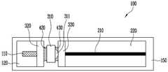
도 1은 본 발명의 일 실시예의 측면도이고, 도 2는 도 1의 실시예의 상면도이다. 본 발명의 일 실시예에 따른 광 모듈(100)은, 기판(150), 상기 기판(150)에 고정되는 복수의 마운트(120, 220, 320, 330), 상기 복수의 마운트에 각각 고정되는 광원(110), 도파로(210) 및 렌즈계(310)를 포함한다.FIG. 1 is a side view of one embodiment of the present invention, and FIG. 2 is a top view of the embodiment of FIG. An
상기 기판(150)은 상기 광 모듈(100)을 전체적으로 지지하는 플랫폼이다. 상기 기판(150) 상에 상기 복수의 마운트(120, 220, 320, 330)가 각각 고정된다. 상기 복수의 마운트(120, 220, 320, 330)는 실질적으로 상기 기판(150)과 일체로 형성될 수도 있고, 개별 부재로 구성되어 각각 상기 기판(150)에 부착될 수도 있다.The
상기 복수의 마운트(120, 220, 320, 330)는, 광원 마운트(120), 도파로 마운트(220) 및 한 쌍의 렌즈 마운트(320, 330)를 포함한다. 상기 광원 마운트(120) 상에는 상기 광원(110)이 실장되며, 상기 도파로 마운트(220) 상에는 상기 도파로(210)가 실장된다.The plurality of
상기 광원(110)과 상기 도파로(210)는 상기 광원(110)의 광축(이하, '광축')을 따라 정렬되며, 상기 광원 마운트(120)와 상기 도파로 마운트(220)도 상기 광축에 나란하게 정렬된다. 상기 광축은 도 1의 z축에 나란하다. 그리고 상기 광축에 수직한 방향 중 높이방향을 도 1의 y축 방향으로 정의하고 폭 방향을 도 1의 x축 방향으로 정의한다.The
상기 광원 마운트(120)는 기결정된 높이와 기결정된 폭을 갖고 광축에 나란하게 연장된 대체적인 직육면체이다. 상기 광원(110)은 상기 광원 마운트(120) 상에 고정되어 상기 기판(150)으로부터 기결정된 높이에 위치할 수 있다.The
상기 광원(110)은 반도체 레이저일 수 있다. 상기 광원(110)은 상기 광원 마운트(120)에 플립 칩 본딩(Flip Chip bonding) 방식으로 집적될 수 있다. 다만 이에 한정되는 것은 아니고, 상기 광원(110)은 광 모듈에 구비되는 어떠한 종류의 광원이어도 좋다.The
상기 도파로 마운트(220)는 상기 광축을 따라 상기 광원 마운트(120)와 정렬된다. 상기 도파로 마운트(220)는 상기 광축 방향으로 상기 광원 마운트(120)에서 이격된다. 상기 도파로 마운트(220)는 기결정된 높이와 기결정된 폭을 갖고 광축에 나란하게 연장된 대체적인 직육면체이다.The
상기 도파로(210)는 상기 광축을 따라 연장되며, 상기 광원(110)에서 출력되는 빔이 입력된다. 상기 도파로(210)의 입력단은 상기 광원(110)의 출력단에서 광축 방향으로 이격되어 위치한다.The
상기 렌즈계(310)는 상기 광원(110)과 상기 도파로(210)를 광 결합한다. 상기 렌즈계(310)는 상기 광원(110) 및 상기 도파로(210)와 광 정렬되는 렌즈(311)를 포함한다. 상기 렌즈(311)는 상기 도파로(210)를 향한 면은 볼록한 구면이고 상기 광원(110)을 향한 면은 평평하나 본 발명이 이에 한정되는 것은 아니다. 상기 렌즈는 상기 광원(110)에서 출력된 빔을 상기 도파로(210)로 집광시킬 수 있는 어떠한 형상의 렌즈여도 좋다.The
상기 광원(110)의 출력단이 상기 렌즈(311)의 초점거리에 놓이도록 상기 광원(110)과 상기 렌즈(311)가 광축을 따라 이격된다. 그리고 상기 도파로(210)의 입력단이 상기 렌즈(311)의 초점거리에 놓이도록 상기 렌즈(311)와 상기 도파로(210)가 상기 광축을 따라 이격된다. 상기 광원(110)에서 출력된 레이저 빔(1)은 상기 렌즈(311)의 구면을 통과하면서 수렴(2)되고 상기 도파로(210)로 집속된다.The
상기 렌즈계(310)는, 상기 렌즈(311)를 지지하고 상기 렌즈계(310)를 상기 한 쌍의 렌즈 마운트(320, 330)에 고정하는 렌즈 지지대(312)를 포함한다. 상기 렌즈 지지대(312)는 상기 렌즈(311)를 둘러싸며, 높이방향을 따라 상기 렌즈(311)에서 아래로 더 연장되어 상기 한 쌍의 렌즈 마운트(320, 330) 사이에 위치한다.The
상기 한 쌍의 렌즈 마운트(320, 330)는 상기 광원(110)과 상기 렌즈계(310) 사이의 이격 공간에 구비되는 제1 렌즈 마운트(320) 및 상기 도파로(210)와 상기 렌즈계(310) 사이의 이격 공간에 구비되는 제2 렌즈 마운트(330)를 포함한다.The pair of lens mounts 320 and 330 may include a
그리고 본 발명의 일 실시예에 따른 광 모듈(100)은 상기 제1 렌즈 마운트(320)에 상기 렌즈 지지대(312)를 고정하는 제1 접착제(420) 및 상기 제2 렌즈 마운트(330)에 상기 렌즈 지지대(312)를 고정하는 제2 접착제(430)를 더 포함한다.The
상기 제1 렌즈 마운트(320)는 광축 방향으로 이격된 상기 광원(110)과 상기 렌즈계(310) 사이에 구비되며, 높이는 상기 광원(110)에서 출력되는 빔(1)이 모두 상기 렌즈(311)로 입사될 수 있을 정도로 낮다. 즉 상기 제1 렌즈 마운트(320)는 광 경로를 가로막지 않을 정도의 높이를 갖는다. 그리고 상기 제1 렌즈 마운트(320)가 광축 방향을 따라 연장되는 길이는 대략적으로 상기 광축 방향으로 상기 광원(110)과 상기 렌즈 지지대(312)가 이격된 거리보다 약간 짧다. 상기 제1 렌즈 마운트(320)는 상기 광원 마운트(120) 및 상기 기판(150)에 각각 닿아 지지될 수 있으며 상기 렌즈 지지대(312)와는 미세한 틈이 유지될 정도로 광축 방향을 따라 연장된다.The
상기 제1 렌즈 마운트(320)는 실질적으로 상기 광원 마운트(120)와 일체로 형성될 수도 있고 별개로 형성되어 조립될 수도 있다. 상기 제1 렌즈 마운트(320)와 상기 광원 마운트(120)가 일체로 형성되는 경우, 상기 광원(110)의 높이를 유지하기 위해 상기 광원(110)을 지지하는 부분, 즉 상기 광원(110)의 출력단이 위치하는 부분까지를 상기 광원 마운트(120)로 볼 수 있을 것이다. 그리고 상기 광원(110)의 높이보다 낮은 높이를 가지며 광축 방향에 대해서 상기 광원(110)과 상기 렌즈 지지대(312) 사이의 이격 공간을 채우는 부분을 상기 제1 렌즈 마운트(320)로 볼 수 있을 것이다.The
상기 제1 렌즈 마운트(320)와 상기 렌즈 지지대(312) 사이의 미세한 틈의 크기는, 상기 렌즈(311)가 상기 제1 렌즈 마운트(320)와의 간섭 없이 x축 및 y축 위치 이동이 가능할 정도이면 된다. 예를 들어, 약 10㎛ 내외일 수 있다.The size of the fine gap between the
상기 제1 접착제(420)가 상기 제1 렌즈 마운트(320)와 상기 렌즈 지지대(312) 사이의 미세한 틈을 메워 상기 렌즈 지지대(312)를 상기 제1 렌즈 마운트(320)에 고정한다. 상기 제1 접착제(420)는 경화된 에폭시일 수 있다. 상기 제1 접착제(420)가 에폭시인 경우 UV 에폭시 경화 방식에 따라 경화된 것일 수 있으며, 이때 상기 제1 렌즈 마운트(320)는 광학적으로 투명한 재질로 이루어질 수 있다. 예를 들어 상기 제1 렌즈 마운트(320)는 실리카(silica) 물질을 포함할 수 있다.The
상기 제2 렌즈 마운트(330)는 광축 방향으로 이격된 상기 도파로(210)와 상기 렌즈계(310) 사이에 구비되며, 높이는 상기 렌즈(311)에서 출력되는 빔(2)이 모두 상기 도파로(210)로 입사될 수 있을 정도로 낮다. 즉 상기 제2 렌즈 마운트(330)는 광 경로를 가로막지 않을 정도의 높이를 갖는다. 그리고 상기 제2 렌즈 마운트(330)가 광축 방향을 따라 연장되는 길이는 대략적으로 상기 광축 방향으로 상기 도파로(210)와 상기 렌즈 지지대(312)가 이격된 거리보다 약간 짧다. 상기 제2 렌즈 마운트(330)는 상기 도파로 마운트(220) 및 상기 기판(150)에 각각 닿아 지지될 수 있으며 상기 렌즈 지지대(312)와는 미세한 틈이 유지될 정도로 광축 방향을 따라 연장된다.The
상기 제2 렌즈 마운트(330)는 실질적으로 상기 도파로 마운트(220)와 일체로 형성될 수도 있고 별개로 형성되어 조립될 수도 있다. 상기 제2 렌즈 마운트(330)와 상기 도파로 마운트(220)가 일체로 형성되는 경우, 상기 도파로(210)의 높이를 유지하기 위해 상기 도파로(210)를 지지하는 부분, 즉 상기 도파로(210)의 입력단이 위치하는 부분까지를 상기 도파로 마운트(220)로 볼 수 있을 것이다. 그리고 상기 도파로(210)의 높이보다 낮은 높이를 가지며 광축 방향에 대해서 상기 도파로(210)와 상기 렌즈 지지대(312) 사이의 이격 공간을 채우는 부분을 상기 제2 렌즈 마운트(330)로 볼 수 있을 것이다.The
상기 제2 렌즈 마운트(330)와 상기 렌즈 지지대(312) 사이의 미세한 틈의 크기는, 상기 렌즈(311)가 상기 제2 렌즈 마운트(330)와의 간섭 없이 x축 및 y축 위치 이동이 가능할 정도이면 된다. 예를 들어, 약 10㎛ 내외일 수 있다.The size of the fine gap between the
상기 제2 접착제(430)가 상기 제2 렌즈 마운트(330)와 상기 렌즈 지지대(312) 사이의 미세한 틈을 메워 상기 렌즈 지지대(312)를 상기 제2 렌즈 마운트(330)에 고정한다. 상기 제2 접착제(430)는 경화된 에폭시일 수 있다. 상기 제2 접착제(430)가 에폭시인 경우 UV 에폭시 경화 방식에 따라 경화된 것일 수 있으며, 이때 상기 제2 렌즈 마운트(330)는 광학적으로 투명한 재질로 이루어질 수 있다. 예를 들어 상기 제2 렌즈 마운트(330)는 실리카(silica) 물질을 포함할 수 있다.The
상기 광원과 상기 도파로의 광 정렬 및 제1 접착제와 제2 접착제에 의한 고정 방법은 후술한다.The optical alignment of the light source and the waveguide and the fixing method using the first adhesive and the second adhesive will be described later.
상술한 바와 같이 상기 렌즈(311)는 광축 방향으로 상기 광원(110) 및 상기 도파로(210)와 각각 초점거리만큼 이격되므로 그 사이에 이격 공간이 존재한다. 상기 한 쌍의 렌즈 마운트(320, 330)는 이러한 이격 공간을 채워 광축 방향의 광 정렬 자유도를 제거함으로서 광 정렬 과정을 단순화할 수 있다. 또한 상기 제1 및 제2 접착제가 에폭시인 경우 에폭시 경화 과정에서 발생할 수 있는 θy, θz 방향의 광정렬 오차도 감소되는 효과가 있다. 또한 제1 및 제2 렌즈 마운트의 폭방향 길이 및 높이방향 길이를 조절하여 상기 렌즈 지지대와 렌즈 마운트 간의 접촉 면적을 넓힐 수 있으므로 진동이나 충격과 같은 외력에 대해 보다 안정적인 효과가 있다.As described above, since the
도 3은 본 발명의 다른 실시예의 측면도이고, 도 4는 도 3의 실시예의 상면도이다. 본 발명의 다른 실시예에 따른 광 모듈(100')은, 기판(150'), 상기 기판(150')에 고정되는 복수의 마운트(120, 220, 320, 330), 상기 복수의 마운트에 각각 고정되는 광원(110), 도파로(210) 및 렌즈계(310), 및 상기 렌즈계(310)를 한 쌍의 렌즈 마운트에 고정시키는 제1 및 제2 접착제(420, 430)를 포함한다.Figure 3 is a side view of another embodiment of the present invention, and Figure 4 is a top view of the embodiment of Figure 3; An optical module 100 'according to another embodiment of the present invention includes a substrate 150', a plurality of
상기 복수의 마운트(120, 220, 320, 330), 상기 광원(110), 상기 도파로(210), 상기 렌즈계(310), 상기 제1 및 제2 접착제(420, 430)는 각각 도 1 및 도 2를 참조하여 상술한 바와 같으므로 상세한 설명을 생략한다.The plurality of
상기 기판(150')은 상기 광 모듈(100')을 전체적으로 지지하는 플랫폼이다. 상기 기판(150')은 복수의 마운트(120, 220, 320, 330)가 모두 탑재될 수 있는 판상의 기판 바디(151)를 포함한다. 상기 기판 바디(151)에는 상기 제1 및 제2 접착제(420, 430)를 투입하기 위한 관통공(152)이 형성된다.The substrate 150 'is a platform for supporting the optical module 100' as a whole. The substrate 150 'includes a plate-
도 3에 도시된 기판(150')은 도 4의 Ⅰ-Ⅰ' 방향을 따라 절개하여 바라본 단면을 도시한 것이다. 상기 기판(150')에 형성된 관통공(152)은 상기 렌즈 지지대(312)의 하부를 향해 개방되어 상기 렌즈 지지대(312)의 하부에 존재하는 공간(309)과 연통된다. 또한 상기 기판(150')에 형성된 관통공(152)은 상기 한 쌍의 렌즈 마운트(320, 330)와 상기 렌즈 지지대(312) 사이의 틈과 연통된다.The substrate 150 'shown in FIG. 3 is a cross-sectional view taken along a direction I-I' of FIG. The through
상술한 구성에 의해서, 상기 기판(150')의 저면을 통해 상기 렌즈 지지대(312)의 하부 쪽으로 제1 및 제2 접착제의 공급이 가능하므로 상기 렌즈 지지대(312)의 상부에 위치하는 상기 렌즈(311)나 광원(110)과 도파로(210)가 접착제에 의해 오염될 염려가 없다.The first and second adhesive can be supplied to the lower side of the lens support table 312 through the bottom surface of the substrate 150 ' 311 and the
도 5는 본 발명의 또 다른 실시예에 따른 광 모듈을 도시한 측면도이고, 도 6은 도 5의 실시예의 사시도이다. 본 발명의 또 다른 실시예에 따른 광 모듈(100'')은 기판(150'), 상기 기판(150')에 고정되는 복수의 마운트(120, 220, 360, 370), 상기 복수의 마운트에 각각 고정되는 광원(110), 도파로(210) 및 렌즈계(310), 및 상기 렌즈계(310)를 한 쌍의 렌즈 마운트(360, 370)에 고정시키는 제1 및 제2 접착제(460, 470)를 포함한다.FIG. 5 is a side view showing an optical module according to another embodiment of the present invention, and FIG. 6 is a perspective view of the embodiment of FIG. An optical module 100 '' according to another embodiment of the present invention includes a substrate 150 ', a plurality of
상기 복수의 마운트(120, 220, 360, 370)는, 광원 마운트(120), 도파로 마운트(220) 및 한 쌍의 렌즈 마운트(360, 370)를 포함한다. 상기 광원 마운트(120) 상에는 상기 광원(110)이 실장되며, 상기 도파로 마운트(220) 상에는 상기 도파로(210)가 실장된다. 상기 광원(110), 상기 광원 마운트(120), 상기 도파로(210), 상기 도파로 마운트(220)는 도 1 및 도 2를 참조하여 상술한 바와 같으므로 상세한 설명을 생략한다.The plurality of
상기 렌즈계(310)는 상기 광원(110)과 상기 도파로(210)를 광 결합한다. 상기 렌즈계(310)는 상기 광원(110) 및 상기 도파로(210)와 광 정렬되는 렌즈(311)를 포함한다. 상기 렌즈(311)에 관해서는 도 1 및 도 2를 참조하여 상술한 바와 같으므로 상세한 설명을 생략한다.The
상기 렌즈계(310)는, 상기 렌즈(311)를 지지하고 상기 렌즈계(310)를 상기 한 쌍의 렌즈 마운트(360, 370)에 고정하는 렌즈 지지대(312)를 포함한다. 상기 렌즈 지지대(312)는 상기 렌즈(311)를 둘러싸며, 높이방향을 따라 상기 렌즈(311)에서 아래로 더 연장되어 상기 한 쌍의 렌즈 마운트(360, 370) 사이에 위치한다.The
상기 한 쌍의 렌즈 마운트(360, 370)는 상기 광원(110)과 상기 렌즈계(310) 사이의 이격 공간에 구비되는 제1 렌즈 마운트(360) 및 상기 도파로(210)와 상기 렌즈계(310) 사이의 이격 공간에 구비되는 제2 렌즈 마운트(370)를 포함한다.The pair of lens mounts 360 and 370 may include a
상기 제1 렌즈 마운트(360)는 광축 방향으로 이격된 상기 광원(110)과 상기 렌즈계(310) 사이에 구비된다. 상기 제2 렌즈 마운트(370)는 광축 방향으로 이격된 상기 도파로(210)와 상기 렌즈계(310) 사이에 구비된다.The
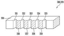
도 7은 제1 및 제2 접착제에 의해 상기 한 쌍의 렌즈 마운트(360, 370) 사이에 고정된 렌즈계(310)를 도시한 상면도이고, 도 8은 상기 제1 또는 제2 렌즈 마운트(360, 370)를 도시한 사시도이다. 상기 제1 렌즈 마운트(360)와 상기 제2 렌즈 마운트(370)는 배치되는 방향이 상이할 뿐 형상 자체는 동일하므로 도 8에 하나로 도시하였다. 이하에서는 제1 렌즈 마운트(360)의 구성을 상세하게 설명하며, 이는 제2 렌즈 마운트(370)에도 동일하게 적용된다.FIG. 7 is a top view showing a
상기 제1 렌즈 마운트(360)는 마운트 바디(350) 및 상기 마운트 바디(350)의 일측면에 형성된 복수의 홈(351, 352, 353, 354, 355)을 포함한다. 상기 제1 및 제2 렌즈 마운트(360, 370)는 도 1 및 도 2의 제1 및 제2 렌즈 마운트(320, 330)에 각각 복수의 홈이 더 구비된 것으로, 상기 마운트 바디(350)는 도 1 및 도 2를 참조하여 상술한 제1 및 제2 렌즈 마운트(320, 330)와 형상이 동일하다. 따라서 상기 마운트 바디(350)에 대해서는 상세한 설명을 생략한다.The
상기 복수의 홈(351, 352, 353, 354, 355)은 상기 마운트 바디(350)가 상기 렌즈 지지대(312)와 마주보는 면 상에 기결정된 깊이로 형성된다. 상기 복수의 홈(351, 352, 353, 354, 355)은 높이방향을 따라 상기 마운트 바디(350)의 하부에서 상부까지 연장되며, 상기 마운트 바디(350)의 상부 및 하부를 향해 개방된다. 그리고 상기 복수의 홈(351, 352, 353, 354, 355)은 서로 이격되어 나란하게 연장되며, 그 사이에 복수의 면(356, 357, 358, 359)이 위치한다.The plurality of
상기 복수의 면(356, 357, 358, 359)과 상기 렌즈 지지대(312) 사이에는 미세한 틈이 있으며, 상기 제1 접착제(460)와 상기 제2 접착제(470)는 각각 상기 복수의 면 및 복수의 홈과 상기 렌즈 지지대(312) 사이의 공간을 채워 상기 렌즈계(310)를 상기 한 쌍의 렌즈 마운트(360, 370)에 고정한다. 상기 복수의 면(356, 357, 358, 359)과 상기 렌즈 지지대(312) 사이의 틈의 크기는 상기 렌즈(311)가 상기 제1 및 제2 렌즈 마운트(360, 370)와의 간섭 없이 x축 및 y축 위치 이동이 가능할 정도이면 된다. 예를 들어, 약 10㎛ 내외일 수 있다.There is a fine gap between the plurality of
상기 복수의 홈(351, 352, 353, 354, 355)은 모세관 현상에 의해서 제1 및 제2 접착제가 이동할 수 있을 정도의 폭을 갖는다. 도 8을 참조하면, 상기 복수의 홈(351, 352, 353, 354, 355)은 상기 마운트 바디의 표면에서 함몰될수록 점점 좁아지며, x-z축 평면에서 본 단면 형상이 삼각형이나 이에 한정되는 것은 아니다.The plurality of
본 실시예에서 상기 복수의 홈(351, 352, 353, 354, 355)은 5개이나 본 발명이 이에 한정되는 것은 아니다. 상기 복수의 홈의 크기, 개수와 이격 거리는 필요에 따라 가감될 수 있다. 상기 제1 및 제2 렌즈 마운트와 상기 렌즈계 사이의 이격거리가 10㎛이내인 경우 접촉면에서의 정지 마찰력(Stiction)과 정전기력이 정렬 장치의 정밀도에 영향을 미치게 된다. 상기 제1 및 제2 렌즈 마운트와 상기 렌즈계의 접촉 면적이 커질수록 정지마찰력 및 정전기력도 커지므로, 상기 복수의 홈의 개수와 이격 거리를 상기 정지마찰력 및 정전기력이 충분히 감소하도록 결정하여 광 정렬의 정밀도를 향상시킬 수 있다.In this embodiment, the number of the
한편, 상기 렌즈계와 상기 제1 및 제2 렌즈 마운트 간의 결합 강도 역시 접촉 면적에 비례하므로 상기 복수의 홈의 크기, 개수와 이격 거리는 결합 강도도 함께 고려하여 결정할 수 있다.Meanwhile, since the coupling strength between the lens system and the first and second lens mounts is also proportional to the contact area, the size, number and spacing distance of the plurality of grooves can be determined in consideration of the coupling strength.
상기 제1 접착제(460)는 상기 제1 렌즈 마운트(360)와 상기 렌즈 지지대(312) 사이의 틈을 메워 상기 렌즈 지지대(312)를 상기 제1 렌즈 마운트(360)에 고정한다. 구체적으로, 상기 제1 접착제(460)는 상기 제1 렌즈 마운트(360)에 형성된 복수의 홈 및 상기 복수의 홈 사이마다 위치하는 면과 상기 렌즈 지지대(312) 사이의 틈을 채운다.The
상기 제2 접착제(470)는 상기 제2 렌즈 마운트(370)와 상기 렌즈 지지대(312) 사이의 틈을 메워 상기 렌즈 지지대(312)를 상기 제2 렌즈 마운트(370)에 고정한다. 구체적으로, 상기 제2 접착제(470)는 상기 제2 렌즈 마운트(370)에 형성된 복수의 홈 및 상기 복수의 홈 사이마다 위치하는 면과 상기 렌즈 지지대(312) 사이의 틈을 채운다.The second
다만, 상기 렌즈계(310)의 폭 크기에 따라 상기 제1 및 제2 렌즈 마운트(360, 370) 각각의 가장 외곽에 있는 홈들(351, 355)에는 상기 제1 접착제(460)와 상기 제2 접착제(470)가 부분적으로만 채워질 수 있다.However, depending on the width of the
상기 제1 접착제(460)와 상기 제2 접착제(470)는 경화된 에폭시일 수 있다. 상기 제1 및 제2 접착제가 에폭시인 경우, 점도에 따라서 상기 한 쌍의 렌즈 마운트와 렌즈 지지대(312) 사이의 틈으로 에폭시를 공급하는 과정에서 에폭시가 주변으로 번질 수 있는데, 복수의 홈(351, 352, 353, 354, 355)이 이러한 잔여 에폭시를 저장할 수 있는 공간을 제공하여 에폭시 번짐을 방지한다.The
따라서 복수의 홈(351, 352, 353, 354, 355)이 에폭시를 가두는 댐 기능을 하므로 에폭시 번짐이 방지되고 보다 점도가 낮은 에폭시의 사용이 가능하다. 보다 점도가 낮은 에폭시를 접착제로 사용할 경우 에폭시 주입량을 정밀하게 제어할 수 있고 기포 발생이 감소하여 접합부의 신뢰성이 향상된다. 또한 에폭시 주입 후 추가적인 렌즈의 미세 광정렬 작업 공정 중 점성에 의한 마찰력을 최소화할 수 있으므로 보다 작은 힘으로도 그리퍼가 렌즈를 쥐고 있을 수 있어 쥐는 힘(gripping force)에 의한 렌즈계의 파손 우려가 감소한다.Therefore, since the plurality of
상기 기판(150')은 상기 광 모듈(100'')을 전체적으로 지지하는 플랫폼이다. 상기 기판(150')은 복수의 마운트(120, 220, 360, 370)가 모두 탑재될 수 있는 판상의 기판 바디(151)를 포함한다. 상기 기판 바디(151)에는 상기 제1 및 제2 접착제(460, 470)를 투입하기 위한 관통공(152)이 형성된다.The substrate 150 'is a platform that supports the optical module 100' 'as a whole. The substrate 150 'includes a plate-
도 5에 도시된 기판(150')은 도 6의 Ⅱ-Ⅱ' 방향을 따라 절개하여 바라본 단면을 도시한 것이다. 상기 기판(150')에 형성된 관통공(152)은 하부를 향해 개방된 상기 복수의 홈(351, 352, 353, 354, 355)과 연통되고, 상기 복수의 면(356, 357, 358, 359)과 상기 렌즈 지지대(312) 사이의 틈과도 연통된다. 상기 관통공(152)의 지름은 상기 렌즈 지지대(312)와 상기 한 쌍의 렌즈 마운트(360, 370) 사이의 틈으로 제1 및 제2 접착제를 공급할 수 있을 정도로 크다.The substrate 150 'shown in FIG. 5 is a cross-sectional view taken along the II-II' direction of FIG. The through
도 1 및 도 3의 실시예와 비교할 때 도 5의 실시예에서는 상기 복수의 홈(351, 352, 353, 354, 355)에 의해서 상기 한 쌍의 렌즈 마운트(360, 370)와 상기 렌즈 지지대(312) 간 접촉 면적이 더 작아지게 된다. 이에 따라 상기 렌즈 지지대(312)와 상기 한 쌍의 렌즈 마운트 사이의 정지 마찰력과 정전기력도 감소하므로 광 정렬시 상기 렌즈계(310)의 위치 제어 동작이 상기 정지 마찰력 및 정전기력에 방해받지 않거나 방해받는 정도가 최소화되는 효과가 있다.5, the lens mounts 360, 370 and the lens mounts 351, 352, 353, 354, 355 are formed in the embodiment of FIG. 312 contact area becomes smaller. As a result, the static frictional force and the electrostatic force between the
따라서 상술한 구성의 한 쌍의 렌즈 마운트에 의해서 광축 방향의 광 정렬 자유도를 제거하고 렌즈계와의 접촉 면적을 증가시키면서도 정지 마찰력 및 정전기력이 광 정렬에 미치는 영향을 최소화할 수 있으므로 보다 정밀한 광정렬이 가능하다.Therefore, the pair of lens mounts having the above-described structure can eliminate the degree of freedom of alignment in the optical axis direction and increase the contact area with the lens system, while minimizing the effect of static frictional force and electrostatic force on optical alignment. Do.
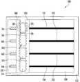
도 9는 본 발명의 일 실시예에 따른 다채널 광 모듈(500)을 도시한 상면도이고, 도 10은 도 9의 실시예에 구비되는 기판의 사시도이다. 본 발명의 일 실시예에 따른 다채널 광 모듈(500)은, 기판(510), 상기 기판(510)에 고정된 복수의 마운트(520, 530, 560, 570), 복수의 광원(541, 542, 543, 544), 복수의 도파로(551, 552, 553, 554), 복수의 렌즈계(501, 502, 503, 504)를 포함한다. 그리고 상기 복수의 마운트는 광원 마운트(520), 도파로 마운트(530) 및 한 쌍의 렌즈 마운트(560, 570)을 포함한다.FIG. 9 is a top view illustrating a multi-channel
도 9의 실시예는 도 5의 실시예의 광 모듈을 다채널로 구현한 일 예로서, 채널별 광원, 렌즈계 및 도파로 간의 연결관계는 도 5의 실시예에서 상술한 바와 실질적으로 동일하다. 따라서 이하에서 생략된 내용은 도 5의 실시예의 대응 구성의 설명으로 대체하여 이해할 수 있다.The embodiment of FIG. 9 is an example in which the optical module of the embodiment of FIG. 5 is implemented in multiple channels, and the connection relationship between the light source, the lens system, and the waveguide for each channel is substantially the same as described above in the embodiment of FIG. Therefore, the contents omitted in the following can be understood in place of the description of the corresponding configuration of the embodiment of Fig.
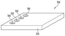
도 9 및 도 10을 참조하면, 상기 기판(510)은 상기 다채널 광 모듈(500)을 전체적으로 지지하는 플랫폼이다. 도면에서 본 실시예의 다채널 광 모듈(500)의 측면도는 도시하지 않았으나 실질적으로 도 5에 도시된 광 모듈(100'')과 동일함을 이해할 수 있을 것이다. 특히 도 5의 광원 마운트(120), 한 쌍의 렌즈 마운트(360, 370), 도파로 마운트(220)는 각각 도 9의 광원 마운트(520), 한 쌍의 렌즈 마운트(560, 570) 및 도파로 마운트(530)에 대응될 수 있으며, 본 실시예에서는 다채널로 구현하기 위하여 각 마운트(520, 530, 560, 570)의 폭이 도 5에서보다 더 넓다.Referring to FIGS. 9 and 10, the
상기 기판(510)은 복수의 마운트(520, 530, 560, 570)가 모두 탑재될 수 있는 판상의 기판 바디(515)를 포함한다. 상기 기판 바디(515)에는 접착제를 투입하기 위해 각 채널마다 구비된 관통공들(511, 512, 513, 514)을 포함한다.The
상기 기판(510)의 측단면 형상은 실질적으로 도 5의 기판(150')의 측단면 형상과 동일하며 다채널로 구현하기 위하여 상기 기판 바디(515)의 폭이 도 5보다 넓고, 도 5의 실시예는 관통공(152)이 하나 형성되나 본 실시예에서는 채널마다 관통공(511, 512, 513, 514)이 구비되는 차이가 있다. 각 채널마다 구비된 관통공(511, 512, 513, 514)의 형상은 실질적으로 도 5의 실시예의 관통공(152)과 동일하다. 다만, 본 발명이 이에 한정되는 것은 아니고, 관통공의 개수는 변형 가능하다. 예를 들어 모든 채널과 연통되는 하나의 관통공이 구비될 수도 있다.5, the width of the
상기 광원 마운트(520)는 도 1을 참조하여 설명한 광원 마운트(120)와 실질적으로 동일하며, 다만 다채널로 구현하기 위해서 폭이 더 넓어지고 복수의 광원(541, 542, 543, 544)이 기결정된 간격으로 나란하게 실장된다. 그리고 상기 도파로 마운트(530)는 도 1을 참조하여 설명한 도파로 마운트(220)와 실질적으로 동일하며, 다만 다채널로 구현하기 위해서 폭이 더 넓어지고 복수의 도파로(551, 552, 553, 554)가 기결정된 간격으로 나란하게 실장된다.The
상기 복수의 광원(541, 542, 543, 544)은 제1 채널 광원(541), 제2 채널 광원(542), 제3 채널 광원(543) 및 제4 채널 광원(544)을 포함한다. 상기 복수의 광원은 폭방향을 따라 일렬로 배열될 수 있다. 제1 내지 제4 채널 광원(541, 542, 543, 544) 각각은 도 1을 참조하여 상술한 광원(110)과 실질적으로 동일하므로 상세한 설명을 생략한다.The plurality of
상기 복수의 도파로(551, 552, 553, 554)는, 상기 제1 채널 광원(541)과 광축 정렬되는 제1 채널 도파로(551), 상기 제2 채널 광원(542)과 광축 정렬되는 제2 채널 도파로(552), 상기 제3 채널 광원(543)과 광축 정렬되는 제3 채널 도파로(553) 및 상기 제4 채널 광원(544)과 광축 정렬되는 제4 채널 도파로(554)를 포함한다. 상기 제1 내지 제4 채널 도파로(551, 552, 553, 554) 각각은 도 1을 참조하여 상술한 도파로(210)와 실질적으로 동일하므로 상세한 설명을 생략한다.The plurality of
상기 복수의 렌즈계(501, 502, 503, 504)는, 상기 제1 채널 광원(541)과 상기 제1 채널 도파로(551)를 광 결합하는 제1 채널 렌즈계(501), 상기 제2 채널 광원(542)과 상기 제2 채널 도파로(552)를 광 결합하는 제2 채널 렌즈계(502), 상기 제3 채널 광원(543)과 상기 제3 채널 도파로(553)를 광 결합하는 제3 채널 렌즈계(503) 및 상기 제4 채널 광원(544)과 상기 제4 채널 도파로(554)를 광 결합하는 제4 채널 렌즈계(504)를 포함한다.The plurality of
상기 제1 내지 제4 채널 렌즈계(501, 502, 503, 504) 각각의 구성은 도 1을 참조하여 상술한 렌즈계(310)와 동일하다. 즉 상기 제1 내지 제4 채널 렌즈계(501, 502, 503, 504)는 각각 렌즈 및 상기 렌즈를 둘러싸고 한 쌍의 렌즈 마운트(560, 570) 사이로 연장되는 렌즈 지지대를 포함한다.The configurations of the first to fourth
상기 한 쌍의 렌즈 마운트(560)는, 각 채널의 광원(541, 542, 543, 544)과 각 채널의 렌즈계(501, 502, 503, 504) 사이의 이격 공간에 구비되는 제1 렌즈 마운트(560) 및 각 채널의 도파로(551, 552, 553, 554)와 각 채널의 렌즈계(501, 502, 503, 504) 사이의 이격 공간에 구비되는 제2 렌즈 마운트(570)를 포함한다. 그리고 본 발명의 일 실시예에 따른 다채널 광 모듈(500)은, 상기 제1 렌즈 마운트(560)에 상기 복수의 렌즈계(501, 502, 503, 504)를 고정하는 제1 접착제(581, 582, 583, 584)가 채널별로 구비되고, 상기 제2 렌즈 마운트(570)에 상기 복수의 렌즈계(501, 502, 503, 504)를 고정하는 제2 접착제(591, 592, 593, 594)가 채널별로 구비된다.The pair of lens mounts 560 includes a first lens mount (not shown) disposed in a space between the
상기 제1 및 제2 렌즈 마운트(560, 570)는 폭방향을 따라 연장되어 각 채널을 가로지르는 렌즈 마운트이다. 상기 제1 렌즈 마운트(560)는, 상기 제1 채널 렌즈계(501)를 마주한 면에 형성된 복수의 제1 채널 홈(561), 상기 제2 채널 렌즈계(502)를 마주한 면에 형성된 복수의 제2 채널 홈(562), 상기 제3 채널 렌즈계(503)를 마주한 면에 형성된 복수의 제3 채널 홈(563) 및 상기 제4 채널 렌즈계(504)를 마주한 면에 형성된 복수의 제4 채널 홈(564)을 구비한다.The first and second lens mounts 560 and 570 are lens mounts extending along the width direction and crossing the respective channels. The
상기 제1 접착제(581, 582, 583, 584)는 각각 상기 제1 렌즈 마운트(560)의 복수의 제1 내지 제4 채널 홈(561, 562, 563, 564)이 형성된 면과 상기 제1 내지 제4 채널 렌즈계(501, 502, 503, 504)의 렌즈 지지대 사이의 틈을 채운다. 구체적으로는, 상기 도 5의 실시예에서 설명한 바와 동일하다.The
상기 제2 렌즈 마운트(570)는, 상기 제1 채널 렌즈계(501)를 향한 면에 형성된 복수의 제1 채널 홈(571), 상기 제2 채널 렌즈계(502)를 향한 면에 형성된 복수의 제2 채널 홈(572), 상기 제3 채널 렌즈계(503)를 향한 면에 형성된 복수의 제3 채널 홈(573) 및 상기 제4 채널 렌즈계(504)를 향한 면에 형성된 복수의 제4 채널 홈(574)을 구비한다.The
상기 제2 접착제(591, 592, 593, 594)는 각각 상기 제2 렌즈 마운트(570)의 복수의 제1 내지 제4 채널 홈(571, 572, 573, 574)이 형성된 면과 상기 제1 내지 제4 채널 렌즈계(501, 502, 503, 504)의 렌즈 지지대 사이의 틈을 채운다. 구체적으로는, 상기 도 5의 실시예에서 설명한 바와 동일하다.The
본 실시예에서 상기 제1 렌즈 마운트(560)는 4개의 채널에 대해서 하나 구비된다. 그리고 상기 제2 렌즈 마운트(570)도 4개의 채널에 대해서 하나 구비된다. 그러나 본 발명이 이에 한정되는 것은 아니고, 다른 실시예로서 상기 제1 및 제2 렌즈 마운트는 채널마다 하나씩 구비되는 개별 마운트들을 포함할 수도 있다.In this embodiment, the
도 11 내지 도 14를 참조하여, 상기 다채널 광 모듈(500)의 광 정렬 방법을 상세하게 설명한다. 이하에서는 다채널 광 모듈(500)의 경우를 예로 설명하지만, 이는 도 5의 실시예에 따른 광 모듈(100'')에도 동일하게 적용된다.The optical alignment method of the multi-channel
도 11 및 도 12를 참조하면, 상기 제1 채널 렌즈계(501)가 그리퍼(15)에 의해 상기 제1 렌즈 마운트(560)와 상기 제2 렌즈 마운트(570) 사이에 삽입된다. 상기 제1 채널 광원(541)과 상기 제1 채널 도파로(551)는 광축 방향으로 서로 이격되고 광축을 따라 정렬된 상태이며, 상기 제1 채널 렌즈계(501)의 초점거리에 상기 제1 채널 광원(541)의 출력단과 상기 제1 채널 도파로(551)의 입력단이 각각 위치하도록 상기 제1 채널 렌즈계(501)의 높이가 결정된다. 광축 방향에 대한 상기 제1 채널 렌즈계(501)의 위치는 상기 제1 및 제2 렌즈 마운트(560, 570)에 의해 이미 결정되어 있으므로 상술한 바와 같이 광축 방향에서의 정렬 자유도는 거의 없다.11 and 12, the first
이렇게 그리퍼(15)를 이용하여 상기 제1 렌즈 마운트(560)와 상기 제2 렌즈 마운트(570) 사이에 상기 제1 채널 렌즈계(501)를 위치시킨 후, 제1 채널 광원(541)에 전원을 인가하고 상기 제1 채널 도파로(551)에 집속되는 광량이 최대가 되도록 x-y 축(도 5에 도시한 x-y-z축 참조)에 대해서 상기 제1 채널 렌즈계(501)의 위치를 조정한다. 상술한 바와 같이 광축 방향(z축 방향)으로는 정렬 자유도가 거의 없으므로 x-y 축으로 움직이는 정렬장치만으로도 상기 제1 채널 렌즈계(501)를 광 정렬할 수 있다.After the first
이렇게 상기 제1 채널 렌즈계(501)의 위치를 조정한 후, 상기 기판(510)의 저면에서 상기 제1채널에 대응되는 관통공(511)을 통해 접착제를 공급하는 노즐(25)을 삽입할 수 있다. 상기 관통공(511)으로 삽입된 노즐(25)은 상기 제1 채널 렌즈계(501)의 하부 공간(309, 도 5 참조)에 도달하고, 상기 제1 및 제2 렌즈 마운트와 상기 제1 채널 렌즈계(501)의 렌즈 지지대 사이로 각각 제1 접착제 및 제2 접착제가 주입될 수 있다. 이하에서는 제1 및 제2 접착제가 에폭시인 경우를 예로 들어 설명한다.After the position of the first
도 13을 참조하면, 제2 렌즈 마운트(570)의 상기 제1 채널 렌즈계(501)를 향한 면에 구비된 복수의 제1 채널 홈(571)를 따라 에폭시(21)가 주입된다. 상기 복수의 제1 채널 홈(571)에서는 모세관 현상에 의해서 상기 제2 렌즈 마운트(570)의 하부에서 상부로, 즉 중력의 반대방향으로 에폭시(21)가 공급될 수 있다. 그 후 상기 제2 렌즈 마운트(570)의 상부로 공급된 에폭시(21)의 양이 증가하면서 상기 제1 채널 렌즈계(501)의 렌즈 지지대와 상기 제2 렌즈 마운트(570)의 접촉부 계면까지 에폭시가 채워지며, 이 계면에서 발생하는 모세관 현상에 의해 에폭시가 계면 사이로 곧바로 스며들게 된다.Referring to FIG. 13, an epoxy 21 is injected along a plurality of
동일한 원리로 상기 제1 렌즈 마운트(560)과 상기 제1 채널 렌즈계(501)의 렌즈 지지대 사이에도 에폭시가 주입된다. 그 후 필요한 경우 추가로 상기 제1 채널 렌즈계(501)를 광 정렬한 후 에폭시를 경화하여 도 14와 같이 상기 제1 채널 렌즈계(501)를 완전히 고정한다. 에폭시 경화방식으로는 예를 들어 UV 에폭시 경화 방식이 사용될 수 있으나 본 발명이 이에 한정되는 것은 아니다.Epoxy is also injected between the
이러한 방식으로 제2 내지 제4 채널 렌즈계(502, 503, 504)를 설치하여 채널별로 광 정렬할 수 있다. 또는 동일한 원리로 제1 내지 제4 채널 렌즈계(501, 502, 503, 504)를 동시에 고정할 수도 있을 것이다.In this manner, the second to fourth
제1 및 제2 렌즈 마운트(460, 470)에 채널별로 구비되는 복수의 홈에 의해서 점도가 낮은 에폭시를 사용하면서도 옆 채널로 에폭시가 번지는 것이 방지되므로 소형의 다채널 광모듈의 구현이 가능하다. 또한 점도가 낮은 에폭시의 사용이 가능하므로 렌즈 마운트의 홈에서 에폭시가 모세관 현상에 의해 상승할 때 공기를 밀어내어 기포발생이 줄어들고 접합부의 신뢰도가 향상된다. 또한 점도가 낮은 에폭시의 사용이 가능하므로 에폭시의 점성에 따른 마찰력도 감소하여 그리퍼(15)에 요구되는 쥐는 힘(gripping force)를 줄일 수 있으며 따라서 렌즈계의 파손이 방지되는 효과가 있다.Since the epoxy having a low viscosity is used by the plurality of grooves provided for each channel in the first and second lens mounts 460 and 470, the epoxy is prevented from spreading to the side channel, thereby realizing a compact multi-channel optical module . In addition, low-viscosity epoxy can be used, so that when the epoxy is raised by capillary action in the groove of the lens mount, the air is pushed out to reduce the occurrence of bubbles and improve the reliability of the joint. In addition, since the epoxy having a low viscosity can be used, the frictional force according to the viscosity of the epoxy is also reduced, so that the gripping force required for the
한편, 도 3의 실시예에서도 노즐(25)을 관통공(152)에 삽입하여 제1 및 제2 렌즈 마운트(320, 330)와 렌즈계의 렌즈 지지대(312) 사이로 에폭시를 주입할 수 있다. 도 1의 실시예의 경우 노즐(25)을 한 쌍의 렌즈 마운트의 측부나 상부 등으로 접근시켜 에폭시의 주입이 가능할 것이다.3, the
도 15는 납땜 용융 방식이 적용된 광 모듈로, 미국등록특허 제 8,346,037호(US 8346037 B2)에서 제안되었다. 도 15의 광 모듈은 도파로(30)와 레이저(60) 사이에 볼 렌즈(50)를 삽입한 후 광출력 방향에 대해 스프링(40)을 이용하여 위치를 조정하여 도파로(30)로 입사되는 광량이 최대치가 되도록 한다. 상기 도파로(30)는 PLC 다중기(Planar Lightwave curcuit multiflexer) (20)의 입력 도파로이다. 상기 볼 렌즈(50)는 기판(10) 상에 에칭된 홀더에 끼워지고, 핸들(90)은 홀더 끝에 위치하여 3축으로 조정 가능하다.FIG. 15 shows an optical module to which a brazing and melting method is applied. US Pat. No. 8,346,037 (US 8346037 B2) proposes an optical module. The optical module of FIG. 15 has a structure in which the
상기 핸들(90)을 조작하여 홀더에 고정된 볼 렌즈(50)의 위치를 조정한 후 납땜(80)을 용융시켜 핸들(90)을 고정한다. 상기 핸들(90)에는 금속 패드(85)가 구비되고 납땜(80)이 용융되면서 핸들(90)이 고정된다. 도 1의 납땜(80)이 구비된 면에 전류가 흐르도록 하여 납땜(80)을 용융시킨다. 핸들이 고정된 후 고속 드라이버 IC(70)가 탑재된다.The
이러한 종래의 광 모듈은 반도체 공정을 이용한 스프링(40) 제작, 납땜(80)의 용융을 위한 고온 히터의 제작 등이 모듈의 구조를 복잡하게 하고 부품 단가가 상승하게 된다.Such a conventional optical module complicates the structure of the module, such as the manufacture of the
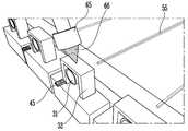
도 16은 레이저 용접 방식이 적용된 광 모듈로, "Lens Alignment Technique Using High-Power Laser for Hybrid Integrated Multi-Channel Transmitter Optical Sub-Assemblies", Tadashi Murao, et. al., IEEE photonics technology letters, Vol.25, No.20, 2013에서 제안되었다. 도 16의 광 모듈은, 도파로(55)와 광원(45) 사이에 열변형에 의해 렌즈(31)의 위치를 변형시키는 렌즈 홀더(32)를 삽입하고, 레이저 헤드(65)에서 출력되는 레이저 빔(66)으로 렌즈 홀더(32)의 프레임을 순간적으로 녹이고 냉각과정에서 발생하는 영구 변형을 이용하여 렌즈(31)의 위치를 조절한다.16 is an optical module to which a laser welding method is applied. As shown in Fig. 16, " Lens Alignment Technique Using High-Power Laser for Hybrid Integrated Multi-Channel Transmitter Optical Subassemblies ", Tadashi Murao, et. al., IEEE photonics technology letters, Vol.25, No. 20, 2013. 16 includes a
이러한 종래의 광 모듈은 렌즈 홀더(32)의 정확한 형상 제작과 고가의 고출력 레이저 소스가 요구되고, 고출력 레이저 조사 후 렌즈 홀더의 영구적인 열변형으로 인해 정렬 오류 발생시 수정이 불가능하다.Such a conventional optical module is required to make an accurate shape of the
상술한 본 발명은 에폭시 경화 방식을 적용하여 상술한 종래의 광 모듈의 광 정렬 방식에 비해 광 모듈의 구조와 공정의 단순화가 가능하며 소요부품 비용 및 필요 장비의 비용도 절감되는 효과가 있다.The present invention has the effect of simplifying the structure and process of the optical module compared to the optical alignment method of the conventional optical module by applying the epoxy curing method and reducing the cost of the required parts and the cost of the necessary equipment.
110: 광원120: 광원 마운트
150: 기판210: 도파로
220: 도파로 마운트310: 렌즈계
320, 330: 한 쌍의 렌즈 마운트420, 430: 제1 및 제2 접착제110: light source 120: light source mount
150: substrate 210: waveguide
220: Waveguide mount 310: Lens system
320, 330: a pair of lens mounts 420, 430: first and second adhesive
Claims (15)
Translated fromKorean상기 광원에서 출력된 빔이 입력되는 도파로;
상기 광원과 상기 도파로를 광 결합하는 렌즈계;
상기 광원의 광축에 대해서 상기 광원과 상기 렌즈계 사이에 위치하는 제1 렌즈 마운트;
상기 렌즈계를 상기 제1 렌즈 마운트에 고정하는 제1 접착제;
상기 광원의 광축에 대해서 상기 도파로와 상기 렌즈계 사이에 위치하는 제2 렌즈 마운트; 및
상기 렌즈계를 상기 제2 렌즈 마운트에 고정하는 제2 접착제를 포함하는
광 모듈.Light source;
A waveguide to which the beam output from the light source is input;
A lens system for optically coupling the light source and the waveguide;
A first lens mount positioned between the light source and the lens system with respect to an optical axis of the light source;
A first adhesive for fixing the lens system to the first lens mount;
A second lens mount positioned between the waveguide and the lens system with respect to an optical axis of the light source; And
And a second adhesive for fixing the lens system to the second lens mount
Optical module.
상기 렌즈계는,
상기 광원 및 상기 도파로와 광 정렬되는 렌즈; 및
상기 렌즈를 지지하고, 상기 렌즈에서 연장되어 상기 제1 렌즈 마운트와 상기 제2 렌즈 마운트 사이로 삽입되는 렌즈 지지대를 포함하고,
상기 제1 접착제는 상기 제1 렌즈 마운트와 상기 렌즈 지지대 사이의 틈을 채우고,
상기 제2 접착제는 상기 제2 렌즈 마운트와 상기 렌즈 지지대 사이의 틈을 채우는 것을 특징으로 하는
광 모듈.The method according to claim 1,
The lens system includes:
A lens optically aligned with the light source and the waveguide; And
A lens support that supports the lens and extends from the lens and is inserted between the first lens mount and the second lens mount,
Wherein the first adhesive fills a gap between the first lens mount and the lens support,
And the second adhesive fills a gap between the second lens mount and the lens support.
Optical module.
상기 제1 렌즈 마운트 및 상기 제2 렌즈 마운트 중 적어도 하나는 상기 렌즈계를 향한 면 상에 복수의 홈이 구비되고,
상기 복수의 홈 중 적어도 하나의 홈은 대응되는 접착제에 의해 채워진 것을 특징으로 하는
광 모듈.3. The method of claim 2,
At least one of the first lens mount and the second lens mount has a plurality of grooves on a surface facing the lens system,
Characterized in that at least one groove of the plurality of grooves is filled with a corresponding adhesive
Optical module.
상기 복수의 홈은 상하방향으로 연장되는 것을 특징으로 하는
광 모듈.The method of claim 3,
And the plurality of grooves extend in the vertical direction
Optical module.
상기 복수의 홈은 수평방향으로 서로 이격되는 것을 특징으로 하는
광 모듈.5. The method of claim 4,
Characterized in that the plurality of grooves are spaced apart from one another in the horizontal direction
Optical module.
상기 광원이 실장되는 광원 마운트;
상기 광축 방향으로 상기 광원 마운트와 이격되고, 상기 도파로가 실장되는 도파로 마운트; 및
상기 광원 마운트, 상기 도파로 마운트, 상기 제1 및 제2 렌즈 마운트를 지지하는 기판을 더 포함하고,
상기 제1 렌즈 마운트는 상기 광원 마운트와 상기 렌즈 지지대 사이에 구비되고,
상기 제2 렌즈 마운트는 상기 도파로 마운트와 상기 렌즈 지지대 사이에 구비되는 것을 특징으로 하는
광 모듈.3. The method of claim 2,
A light source mount on which the light source is mounted;
A waveguide mount which is spaced apart from the light source mount in the optical axis direction and on which the waveguide is mounted; And
Further comprising a substrate supporting the light source mount, the waveguide mount, the first and second lens mounts,
Wherein the first lens mount is provided between the light source mount and the lens support,
And the second lens mount is provided between the waveguide mount and the lens support.
Optical module.
상기 기판은,
상기 제1 렌즈 마운트와 상기 렌즈 지지대 사이의 틈 및/또는 상기 제2 렌즈 마운트와 상기 렌즈 지지대 사이의 틈을 향해 개구된 관통공을 구비하는 것을 특징으로 하는
광 모듈.The method according to claim 6,
Wherein:
And a through hole opened toward a gap between the first lens mount and the lens support and / or a gap between the second lens mount and the lens support.
Optical module.
상기 렌즈 지지대는 상기 렌즈에서 하방으로 연장되고,
상기 기판의 관통공은 상기 렌즈 지지대의 하부를 향해 개구된 것을 특징으로 하는
광 모듈.8. The method of claim 7,
Wherein the lens support extends downward from the lens,
And the through-hole of the substrate is opened toward the lower portion of the lens support.
Optical module.
상기 제1 접착제 및 상기 제2 접착제 중 적어도 하나는 경화된 에폭시인 것을 특징으로 하는
광 모듈.The method according to claim 1,
Characterized in that at least one of the first adhesive and the second adhesive is a cured epoxy
Optical module.
상기 제1 렌즈 마운트 및 상기 제2 렌즈 마운트 중 적어도 하나는 투명한 물질을 포함하는
광 모듈.10. The method of claim 9,
Wherein at least one of the first lens mount and the second lens mount comprises a transparent material
Optical module.
상기 복수의 광원에서 출력된 빔이 각각 입력되는 복수의 도파로;
서로 대응되는 상기 광원과 상기 도파로를 광 결합하는 복수의 렌즈계;
상기 광축 방향에 대해서 상기 복수의 렌즈계와 상기 복수의 광원 사이에 위치하는 적어도 하나의 제1 렌즈 마운트;
상기 복수의 렌즈계를 각각 상기 적어도 하나의 제1 렌즈 마운트에 고정하는 제1 접착제;
상기 광축 방향에 대해서 상기 복수의 렌즈계와 상기 복수의 도파로 사이에 위치하는 적어도 하나의 제2 렌즈 마운트; 및
상기 복수의 렌즈계를 각각 상기 적어도 하나의 제2 렌즈 마운트에 고정하는 제2 접착제를 포함하는
다채널 광 모듈.A plurality of light sources arranged in a direction perpendicular to an optical axis;
A plurality of waveguides into which beams output from the plurality of light sources are respectively input;
A plurality of lens systems optically coupling the light source and the waveguide corresponding to each other;
At least one first lens mount positioned between the plurality of lens systems and the plurality of light sources with respect to the optical axis direction;
A first adhesive for fixing the plurality of lens systems to the at least one first lens mount, respectively;
At least one second lens mount positioned between the plurality of lens systems and the plurality of waveguides with respect to the optical axis direction; And
And a second adhesive for fixing the plurality of lens systems to the at least one second lens mount, respectively
Multichannel optical module.
상기 제1 렌즈 마운트 및 상기 제2 렌즈 마운트 중 적어도 하나는 상기 렌즈계를 향한 면 상에 복수의 홈이 형성되고,
상기 복수의 홈은 서로 이격된 것을 특징으로 하는
다채널 광 모듈.12. The method of claim 11,
Wherein at least one of the first lens mount and the second lens mount has a plurality of grooves formed on a surface facing the lens system,
Characterized in that the plurality of grooves are spaced apart from each other
Multichannel optical module.
상기 복수의 홈은 상기 광축에 수직한 방향으로 연장되는 것을 특징으로 하는
다채널 광 모듈.13. The method of claim 12,
Wherein the plurality of grooves extend in a direction perpendicular to the optical axis
Multichannel optical module.
상기 복수의 홈은 상기 복수의 광원이 서로 이격된 방향에 수직한 방향으로 연장되는 것을 특징으로 하는
다채널 광 모듈.14. The method of claim 13,
Wherein the plurality of grooves extend in a direction perpendicular to a direction in which the plurality of light sources are spaced apart from each other
Multichannel optical module.
상기 복수의 광원이 실장되는 적어도 하나의 광원 마운트;
상기 복수의 도파로가 실장되는 적어도 하나의 도파로 마운트; 및
상기 광원 마운트, 상기 도파로 마운트, 상기 제1 및 상기 제2 렌즈 마운트를 지지하는 기판을 더 포함하고,
상기 기판은,
상기 복수의 렌즈계 중 적어도 하나와 상기 제1 렌즈 마운트 사이 및/또는 상기 복수의 렌즈계 중 적어도 하나와 상기 제2 렌즈 마운트 사이를 향해 개구되고, 상기 기판을 관통하는 관통공을 구비하는 것을 특징으로 하는
다채널 광 모듈.13. The method of claim 12,
At least one light source mount on which the plurality of light sources are mounted;
At least one waveguide mount on which the plurality of waveguides are mounted; And
Further comprising a substrate supporting the light source mount, the waveguide mount, the first and second lens mounts,
Wherein:
And a through hole which is opened toward at least one of the plurality of lens systems and between the first lens mount and / or at least one of the plurality of lens systems and the second lens mount, and penetrates through the substrate
Multichannel optical module.
Priority Applications (2)
| Application Number | Priority Date | Filing Date | Title |
|---|---|---|---|
| KR1020160021811AKR102495205B1 (en) | 2016-02-24 | 2016-02-24 | Optical module |
| US15/210,476US9829660B2 (en) | 2016-02-24 | 2016-07-14 | Optical module |
Applications Claiming Priority (1)
| Application Number | Priority Date | Filing Date | Title |
|---|---|---|---|
| KR1020160021811AKR102495205B1 (en) | 2016-02-24 | 2016-02-24 | Optical module |
Publications (2)
| Publication Number | Publication Date |
|---|---|
| KR20170099568Atrue KR20170099568A (en) | 2017-09-01 |
| KR102495205B1 KR102495205B1 (en) | 2023-02-17 |
Family
ID=59629816
Family Applications (1)
| Application Number | Title | Priority Date | Filing Date |
|---|---|---|---|
| KR1020160021811AActiveKR102495205B1 (en) | 2016-02-24 | 2016-02-24 | Optical module |
Country Status (2)
| Country | Link |
|---|---|
| US (1) | US9829660B2 (en) |
| KR (1) | KR102495205B1 (en) |
Cited By (1)
| Publication number | Priority date | Publication date | Assignee | Title |
|---|---|---|---|---|
| KR20190015069A (en)* | 2017-08-04 | 2019-02-13 | 한국전자통신연구원 | Optical module platform structure and fabrication method |
Families Citing this family (7)
| Publication number | Priority date | Publication date | Assignee | Title |
|---|---|---|---|---|
| US10444448B2 (en)* | 2017-08-04 | 2019-10-15 | Electronics And Telecommunications Research Institute | Optical module platform structure and method of manufacturing the same |
| WO2022015669A1 (en)* | 2020-07-14 | 2022-01-20 | Nlight, Inc. | Opto-mechanical mounting for optical components |
| CN111679382A (en)* | 2020-07-28 | 2020-09-18 | 长飞光纤光缆股份有限公司 | Single lens coupling method and light emitter |
| US11474301B2 (en)* | 2021-01-07 | 2022-10-18 | Advanced Semiconductor Engineering, Inc. | Device for communication |
| US12298572B2 (en)* | 2021-06-25 | 2025-05-13 | Intel Corporation | Device, method and system for optical communication with a photonic integrated circuit chip and a transverse oriented lens structure |
| US12021563B2 (en)* | 2021-08-25 | 2024-06-25 | Electronics And Telecommunications Research Institute | Highly-integrated multi-channel optical module having lens mounting structure for minimizing optical alignment error and lens assembly process thereof |
| WO2023063196A1 (en)* | 2021-10-11 | 2023-04-20 | 古河電気工業株式会社 | Optical apparatus |
Citations (4)
| Publication number | Priority date | Publication date | Assignee | Title |
|---|---|---|---|---|
| US4237474A (en)* | 1978-10-18 | 1980-12-02 | Rca Corporation | Electroluminescent diode and optical fiber assembly |
| US5260587A (en)* | 1991-03-29 | 1993-11-09 | Nec Corporation | Optical semiconductor device array module with light shielding plate |
| JPH07198980A (en)* | 1993-12-28 | 1995-08-01 | Sumitomo Electric Ind Ltd | Optical fiber array manufacturing method |
| WO2015129179A1 (en)* | 2014-02-26 | 2015-09-03 | 日本電気株式会社 | Lens holding structure, lens holder, optical module and lens holding method |
Family Cites Families (6)
| Publication number | Priority date | Publication date | Assignee | Title |
|---|---|---|---|---|
| KR100198460B1 (en) | 1996-10-29 | 1999-06-15 | 이계철 | Optical module with lens aligned in V-groove and method of making same |
| US6418251B1 (en)* | 2000-10-13 | 2002-07-09 | Bogie Boscha | Laser-diode assembly for generating a frequency-stabilized narrow-bandwidth light and a method of narrowing linewidth of the spectrum |
| US20030219211A1 (en) | 2002-05-22 | 2003-11-27 | Yu-Sik Kim | Method for aligning optical axis of an optical module |
| KR100811883B1 (en) | 2005-12-08 | 2008-03-10 | 한국전자통신연구원 | Optical arrangement method and device |
| WO2010088631A2 (en) | 2009-01-30 | 2010-08-05 | Kaiam Corp. | Micromechanically aligned optical assembly |
| US20130051024A1 (en) | 2011-08-31 | 2013-02-28 | Moshe Amit | Optical Transmitter Assembly, Optical Transceivers Including the Same, and Methods of Making and Using Such Optical Transmitter Assemblies and Optical Transceivers |
- 2016
- 2016-02-24KRKR1020160021811Apatent/KR102495205B1/enactiveActive
- 2016-07-14USUS15/210,476patent/US9829660B2/ennot_activeExpired - Fee Related
Patent Citations (4)
| Publication number | Priority date | Publication date | Assignee | Title |
|---|---|---|---|---|
| US4237474A (en)* | 1978-10-18 | 1980-12-02 | Rca Corporation | Electroluminescent diode and optical fiber assembly |
| US5260587A (en)* | 1991-03-29 | 1993-11-09 | Nec Corporation | Optical semiconductor device array module with light shielding plate |
| JPH07198980A (en)* | 1993-12-28 | 1995-08-01 | Sumitomo Electric Ind Ltd | Optical fiber array manufacturing method |
| WO2015129179A1 (en)* | 2014-02-26 | 2015-09-03 | 日本電気株式会社 | Lens holding structure, lens holder, optical module and lens holding method |
Cited By (1)
| Publication number | Priority date | Publication date | Assignee | Title |
|---|---|---|---|---|
| KR20190015069A (en)* | 2017-08-04 | 2019-02-13 | 한국전자통신연구원 | Optical module platform structure and fabrication method |
Also Published As
| Publication number | Publication date |
|---|---|
| US9829660B2 (en) | 2017-11-28 |
| KR102495205B1 (en) | 2023-02-17 |
| US20170242208A1 (en) | 2017-08-24 |
Similar Documents
| Publication | Publication Date | Title |
|---|---|---|
| KR102495205B1 (en) | Optical module | |
| US10054748B2 (en) | Micromechanically aligned optical assembly | |
| JP4559327B2 (en) | Alignment method of optical module using lens and optical module created by the method | |
| EP3066505B1 (en) | Method and system for an optical communication device | |
| US5631991A (en) | Plastic optical subassemblies for light transfer between an optical fiber and an optoelectronic converter and the fabrication of such plastic optical subassemblies | |
| US10338326B2 (en) | Multi-channel optical subassembly structure comprising an alignment jig and method of packaging the structure | |
| EP1629516B1 (en) | True position bench | |
| US20180088282A1 (en) | Optical connecting device, optical processing apparatus, method for fabricating optical processing apparatus | |
| US9592578B2 (en) | Method of manufacturing an assembly to couple an optical fiber to an opto-electronic component | |
| US9261652B2 (en) | Optical components including bonding slots for adhesion stability | |
| JP2008026462A (en) | Optical module | |
| US7085079B2 (en) | Optical element module, and apparatus and method for fixing optical element | |
| EP2860561B1 (en) | Light source device | |
| KR101053545B1 (en) | Photoelectric conversion module | |
| KR20010014000A (en) | Alignment of optical building elements | |
| US6905354B1 (en) | U-clip for optical device alignment | |
| US20060204177A1 (en) | Low cost, high precision multi-point optical component attachment | |
| US7093986B2 (en) | Low cost optical module | |
| van Zantvoort et al. | Fiber array-to-photonic-chip fixation and fine tuning using laser support adjustment | |
| KR102535603B1 (en) | Optical module platform structure and fabrication method | |
| US20230106911A1 (en) | Optical coupling of light source and photonic integrated circuit | |
| JP6360233B1 (en) | Photoelectric conversion unit, optical fiber guide, connector, and method for manufacturing photoelectric conversion unit | |
| JP2005309270A (en) | Optical module and manufacturing method thereof | |
| JP2006350136A (en) | Optical components |
Legal Events
| Date | Code | Title | Description |
|---|---|---|---|
| PA0109 | Patent application | Patent event code:PA01091R01D Comment text:Patent Application Patent event date:20160224 | |
| PG1501 | Laying open of application | ||
| PA0201 | Request for examination | Patent event code:PA02012R01D Patent event date:20210108 Comment text:Request for Examination of Application Patent event code:PA02011R01I Patent event date:20160224 Comment text:Patent Application | |
| E902 | Notification of reason for refusal | ||
| PE0902 | Notice of grounds for rejection | Comment text:Notification of reason for refusal Patent event date:20220929 Patent event code:PE09021S01D | |
| E701 | Decision to grant or registration of patent right | ||
| PE0701 | Decision of registration | Patent event code:PE07011S01D Comment text:Decision to Grant Registration Patent event date:20221215 | |
| GRNT | Written decision to grant | ||
| PR0701 | Registration of establishment | Comment text:Registration of Establishment Patent event date:20230130 Patent event code:PR07011E01D | |
| PR1002 | Payment of registration fee | Payment date:20230131 End annual number:3 Start annual number:1 | |
| PG1601 | Publication of registration |