KR20170097925A - Side button structure of mobile communication terminal - Google Patents
Side button structure of mobile communication terminalDownload PDFInfo
- Publication number
- KR20170097925A KR20170097925AKR1020160019613AKR20160019613AKR20170097925AKR 20170097925 AKR20170097925 AKR 20170097925AKR 1020160019613 AKR1020160019613 AKR 1020160019613AKR 20160019613 AKR20160019613 AKR 20160019613AKR 20170097925 AKR20170097925 AKR 20170097925A
- Authority
- KR
- South Korea
- Prior art keywords
- button
- piezoelectric element
- frame
- protrusion
- hole
- Prior art date
- Legal status (The legal status is an assumption and is not a legal conclusion. Google has not performed a legal analysis and makes no representation as to the accuracy of the status listed.)
- Ceased
Links
- 238000010295mobile communicationMethods0.000titleclaimsabstractdescription31
- 238000000034methodMethods0.000claimsdescription18
- 238000006073displacement reactionMethods0.000claimsdescription6
- 238000004078waterproofingMethods0.000claimsdescription3
- 235000006485Platanus occidentalisNutrition0.000claims2
- 244000268528Platanus occidentalisSpecies0.000claims2
- 230000002093peripheral effectEffects0.000claims2
- 230000008878couplingEffects0.000description4
- 238000010168coupling processMethods0.000description4
- 238000005859coupling reactionMethods0.000description4
- 239000002184metalSubstances0.000description3
- 229910052751metalInorganic materials0.000description3
- 230000010355oscillationEffects0.000description3
- 239000000463materialSubstances0.000description2
- 238000005476solderingMethods0.000description2
- 229920003002synthetic resinPolymers0.000description2
- 239000000057synthetic resinSubstances0.000description2
- PIICEJLVQHRZGT-UHFFFAOYSA-NEthylenediamineChemical compoundNCCNPIICEJLVQHRZGT-UHFFFAOYSA-N0.000description1
- 239000000853adhesiveSubstances0.000description1
- 230000001070adhesive effectEffects0.000description1
- LFVGISIMTYGQHF-UHFFFAOYSA-Nammonium dihydrogen phosphateChemical compound[NH4+].OP(O)([O-])=OLFVGISIMTYGQHF-UHFFFAOYSA-N0.000description1
- 229910000387ammonium dihydrogen phosphateInorganic materials0.000description1
- JRPBQTZRNDNNOP-UHFFFAOYSA-Nbarium titanateChemical compound[Ba+2].[Ba+2].[O-][Ti]([O-])([O-])[O-]JRPBQTZRNDNNOP-UHFFFAOYSA-N0.000description1
- 229910002113barium titanateInorganic materials0.000description1
- 239000013078crystalSubstances0.000description1
- 230000000694effectsEffects0.000description1
- 238000005516engineering processMethods0.000description1
- -1for exampleSubstances0.000description1
- 239000007769metal materialSubstances0.000description1
- 235000019837monoammonium phosphateNutrition0.000description1
- 239000006012monoammonium phosphateSubstances0.000description1
- 230000010287polarizationEffects0.000description1
- LJCNRYVRMXRIQR-OLXYHTOASA-Lpotassium sodium L-tartrateChemical compound[Na+].[K+].[O-]C(=O)[C@H](O)[C@@H](O)C([O-])=OLJCNRYVRMXRIQR-OLXYHTOASA-L0.000description1
- 235000011006sodium potassium tartrateNutrition0.000description1
- 229910001220stainless steelInorganic materials0.000description1
- 239000010935stainless steelSubstances0.000description1
- 239000000758substrateSubstances0.000description1
- 229940070527tourmalineDrugs0.000description1
- 229910052613tourmalineInorganic materials0.000description1
- 239000011032tourmalineSubstances0.000description1
Images


Classifications
- H—ELECTRICITY
- H01—ELECTRIC ELEMENTS
- H01H—ELECTRIC SWITCHES; RELAYS; SELECTORS; EMERGENCY PROTECTIVE DEVICES
- H01H57/00—Electrostrictive relays; Piezoelectric relays
- H—ELECTRICITY
- H03—ELECTRONIC CIRCUITRY
- H03K—PULSE TECHNIQUE
- H03K17/00—Electronic switching or gating, i.e. not by contact-making and –breaking
- H03K17/94—Electronic switching or gating, i.e. not by contact-making and –breaking characterised by the way in which the control signals are generated
- H03K17/96—Touch switches
- H03K17/964—Piezoelectric touch switches
- H—ELECTRICITY
- H01—ELECTRIC ELEMENTS
- H01H—ELECTRIC SWITCHES; RELAYS; SELECTORS; EMERGENCY PROTECTIVE DEVICES
- H01H13/00—Switches having rectilinearly-movable operating part or parts adapted for pushing or pulling in one direction only, e.g. push-button switch
- H01H13/02—Details
- H01H13/12—Movable parts; Contacts mounted thereon
- H01H13/14—Operating parts, e.g. push-button
- H—ELECTRICITY
- H01—ELECTRIC ELEMENTS
- H01H—ELECTRIC SWITCHES; RELAYS; SELECTORS; EMERGENCY PROTECTIVE DEVICES
- H01H13/00—Switches having rectilinearly-movable operating part or parts adapted for pushing or pulling in one direction only, e.g. push-button switch
- H01H13/02—Details
- H01H13/10—Bases; Stationary contacts mounted thereon
- H—ELECTRICITY
- H04—ELECTRIC COMMUNICATION TECHNIQUE
- H04M—TELEPHONIC COMMUNICATION
- H04M1/00—Substation equipment, e.g. for use by subscribers
- H04M1/02—Constructional features of telephone sets
- H04M1/23—Construction or mounting of dials or of equivalent devices; Means for facilitating the use thereof
- H04M1/236—Construction or mounting of dials or of equivalent devices; Means for facilitating the use thereof including keys on side or rear faces
- H—ELECTRICITY
- H10—SEMICONDUCTOR DEVICES; ELECTRIC SOLID-STATE DEVICES NOT OTHERWISE PROVIDED FOR
- H10N—ELECTRIC SOLID-STATE DEVICES NOT OTHERWISE PROVIDED FOR
- H10N30/00—Piezoelectric or electrostrictive devices
- H10N30/30—Piezoelectric or electrostrictive devices with mechanical input and electrical output, e.g. functioning as generators or sensors
- H—ELECTRICITY
- H10—SEMICONDUCTOR DEVICES; ELECTRIC SOLID-STATE DEVICES NOT OTHERWISE PROVIDED FOR
- H10N—ELECTRIC SOLID-STATE DEVICES NOT OTHERWISE PROVIDED FOR
- H10N30/00—Piezoelectric or electrostrictive devices
- H10N30/80—Constructional details
- H10N30/88—Mounts; Supports; Enclosures; Casings
- H—ELECTRICITY
- H01—ELECTRIC ELEMENTS
- H01H—ELECTRIC SWITCHES; RELAYS; SELECTORS; EMERGENCY PROTECTIVE DEVICES
- H01H2201/00—Contacts
- H01H2201/02—Piezo element
- H—ELECTRICITY
- H01—ELECTRIC ELEMENTS
- H01H—ELECTRIC SWITCHES; RELAYS; SELECTORS; EMERGENCY PROTECTIVE DEVICES
- H01H2221/00—Actuators
- H01H2221/05—Force concentrator; Actuating dimple
- H—ELECTRICITY
- H01—ELECTRIC ELEMENTS
- H01H—ELECTRIC SWITCHES; RELAYS; SELECTORS; EMERGENCY PROTECTIVE DEVICES
- H01H2227/00—Dimensions; Characteristics
- H01H2227/016—Switch site protrusions; Force concentrators
- H—ELECTRICITY
- H01—ELECTRIC ELEMENTS
- H01H—ELECTRIC SWITCHES; RELAYS; SELECTORS; EMERGENCY PROTECTIVE DEVICES
- H01H2231/00—Applications
- H01H2231/022—Telephone handset
Landscapes
- Engineering & Computer Science (AREA)
- Signal Processing (AREA)
- Telephone Set Structure (AREA)
Abstract
Translated fromKorean
Description
Translated fromKorean본 발명은 이동통신 단말기의 사이드 버튼 구조에 관한 것으로, 보다 상세하게는 압전 소자를 이용한 사이드 버튼 구조에 관한 것이다.BACKGROUND OF THE INVENTION 1. Field of the Invention The present invention relates to a side button structure of a mobile communication terminal, and more particularly to a side button structure using a piezoelectric element.
일반적으로 이동통신 단말기의 사이드 버튼은 단말기 본체의 한쪽 측면 또는 양쪽 측면에 설치되며, 사용자 조작을 통해 전원 온/오프, 단말기 잠금/해제, 볼륨 조절 등의 각종 기능을 실행할 수 있도록 하는 버튼의 일종이다.Generally, the side buttons of the mobile communication terminal are installed on one side or both sides of the main body of the terminal, and are a type of button for performing various functions such as power on / off, terminal lock / unlock, volume control .
이동통신 단말기의 사이드 버튼에는 주로 돔(Dome) 스위치 방식과 택트(Tact) 스위치 방식이 채용된다.The side buttons of the mobile communication terminal mainly employ a dome switch mode and a tact switch mode.
돔 스위치 방식은 돔 스위치가 내장된 돔 쉬트를 연성회로기판(Flexible Printed Circuit Board; FPCB)에 부착하여 메인회로기판에 형성된 접속 단자 즉, 로우(Row) 및 컬럼(Column) 단자패드에 상기 연성회로기판을 납땜 연결하는 방식이다. 돔 스위치는 러버(Rubber) 돔 스위치 또는 메탈(Metal) 돔 스위치가 사용된다.In the dome switch type, a dome sheet having a dome switch is attached to a flexible printed circuit board (FPCB) and connected to a connection terminal formed on a main circuit board, that is, a row and a column terminal pad, And the substrate is connected by soldering. Rubber dome switches or metal dome switches are used for the dome switches.
택트 스위치 방식은 택트 스위치 소자를 메인회로기판에 형성된 로우(Row) 및 컬럼(Column) 단자 패드에 납땜 연결하는 방식이다. 요즘 택트 스위치는 표면실장기술(SMT;Surface Mount Technology)이 적용된 표면실장소자(SMD;Surface Mount Devices)를 사용한다.The tact switch method is a method of soldering the tact switch element to the row and column terminal pads formed on the main circuit board. Today's tact switches use Surface Mount Devices (SMD) with Surface Mount Technology (SMT).
그런데 돔 스위치를 사용하는 경우, 돔 쉬트를 부착하기 위한 연성회로기판을 제작해야 하며, 연성회로기판을 메인회로기판에 납땜해야 한다. 그리고 연성회로기판을 고정하기 위해 메인회로기판의 측면에 고정 지지대를 세워야 하며, 양면 테이프로 고정해 줘야 한다.However, when using a dome switch, a flexible circuit board for attaching the dome sheet must be manufactured, and the flexible circuit board should be soldered to the main circuit board. In order to fix the flexible circuit board, a fixing support should be installed on the side of the main circuit board and fixed with a double-sided tape.
택트 스위치를 사용하는 경우 택트 스위치는 사이드 버튼의 숫자에 맞춰 메인회로기판에 표면실장 해줘야 한다.When using a tact switch, the tact switch must be surface-mounted to the main circuit board in accordance with the number of side buttons.
이와 같이, 돔 스위치 방식은 연성회로기판의 단품가격이 비싸고 조립 공정이 많으며, 메인회로기판은 연성회로기판을 위한 공간을 많이 차지하게 된다. 그리고 택트 스위치 방식은 택트 스위치 단품 가격이 비싸고 표면실장 비용 또한 많이 들며 메인회로기판은 택트 스위치의 두께에 의해 이동통신 단말기의 슬림 추세에 역행하게 된다.As described above, in the dome switch type, the cost of the single component of the flexible circuit board is high, the assembly process is large, and the main circuit board occupies a lot of space for the flexible circuit board. In addition, the tact switch type is expensive, the surface mounting cost is high, and the main circuit board is backed by the thickness of the tact switch to the slim trend of the mobile communication terminal.
본 발명이 이루고자 하는 기술적 과제는 기존의 돔 스위치 방식이나 택트 스위치 방식이 아닌, 압전 소자를 이용한 새로운 형태의 이동통신 단말기의 사이드 버튼 구조를 제공하는 데 있다.SUMMARY OF THE INVENTION It is an object of the present invention to provide a side button structure of a new type of mobile communication terminal using a piezoelectric element, rather than a conventional dome switch type or tact switch type.
상기 기술적 과제를 해결하기 위한 본 발명의 일 태양에 따른 이동통신 단말기의 사이드 버튼 구조는, 버튼공이 형성된 프레임; 상기 버튼공에 삽입되며, 내측면에 가압돌기가 형성되는 버튼; 일면이 상기 가압돌기에 닿아 있는 압전 소자; 및 상기 압전 소자의 타면 측에 배치되고 상기 압전 소자의 양측 가장자리를 지지하는 지지부재를 포함한다.According to an aspect of the present invention, there is provided a side button structure for a mobile communication terminal, comprising: a frame having a button hole; A button inserted into the button hole and having a pressing projection formed on an inner surface thereof; A piezoelectric element whose one surface is in contact with the pressing projection; And a support member disposed on the other surface side of the piezoelectric element and supporting both side edges of the piezoelectric element.
상기 지지부재는, 상기 가압돌기에 대응하는 위치에 상기 압전 소자의 타면으로부터 일정 간격 이격되어 상기 압전 소자의 변위를 제한하는 스토퍼돌기가 형성될 수 있다.The support member may be formed at a position corresponding to the pressing projection at a predetermined distance from the other surface of the piezoelectric element to restrict a displacement of the piezoelectric element.
상기 버튼은 내측 양쪽 가장자리에 걸림돌기가 돌출형성되고, 상기 프레임 내측에 상기 걸림돌기가 수용되는 제1 걸림홈이 형성될 수 있다.The button may have a locking protrusion formed on both inner edges thereof, and a first locking groove may be formed on the inner side of the frame to receive the locking protrusion.
상기 이동통신 단말기의 사이드 버튼 구조는, 상기 버튼과 상기 압전 소자 사이에 구비되어 상기 버튼을 탄성 지지하는 판 스프링을 더 포함할 수 있다.The side button structure of the mobile communication terminal may further include a leaf spring provided between the button and the piezoelectric element to elastically support the button.
상기 판 스프링은 상기 걸림돌기를 탄성 지지할 수 있다.The plate spring can elastically support the locking projection.
상기 판 스프링은 상기 버튼의 내측면에 대응하는 구멍이 형성되고, 상기 구멍의 내주면 중 상기 걸림돌기에 대응하는 부분에 상기 구멍 안쪽으로 돌출부가 형성되어 상기 돌출부가 상기 걸림돌기를 탄성 지지할 수 있다.The plate spring has a hole corresponding to the inner surface of the button, and a protruding portion is formed in an inner circumferential surface of the hole corresponding to the locking protrusion so that the protruding portion can elastically support the locking protrusion.
상기 프레임 내측에 상기 판 스프링의 가장자리가 수용되는 제2 걸림홈이 형성될 수 있다.And a second latching groove for receiving the edge of the leaf spring is formed inside the frame.
상기 버튼은 상기 버튼공에 대응하는 외주면 둘레에 방수부재가 구비될 수 있다.The button may be provided with a waterproof member around an outer circumferential surface corresponding to the button hole.
상기 기술적 과제를 해결하기 위한 본 발명의 다른 태양에 따른 이동통신 단말기의 사이드 버튼 구조는, 버튼공이 형성된 프레임; 상기 버튼공에 삽입되며, 내측면에 가압돌기가 형성되는 버튼; 일면이 상기 가압돌기에 닿아 있는 압전 소자; 및 상기 버튼과 상기 압전 소자 사이에 구비되어 상기 버튼을 탄성 지지하는 판 스프링을 포함할 수 있다According to another aspect of the present invention, there is provided a side button structure of a mobile communication terminal, including: a frame having a button hole; A button inserted into the button hole and having a pressing projection formed on an inner surface thereof; A piezoelectric element whose one surface is in contact with the pressing projection; And a leaf spring provided between the button and the piezoelectric element to elastically support the button
상기 버튼은 내측 양쪽 가장자리에 걸림돌기가 돌출형성되고, 상기 프레임 내측에 상기 걸림돌기가 수용되는 제1 걸림홈이 형성될 수 있다.The button may have a locking protrusion formed on both inner edges thereof, and a first locking groove may be formed on the inner side of the frame to receive the locking protrusion.
상기 판 스프링은 상기 걸림돌기를 탄성 지지할 수 있다.The plate spring can elastically support the locking projection.
상기 판 스프링은 상기 버튼의 내측면에 대응하는 구멍이 형성되고, 상기 구멍의 내주면 중 상기 걸림돌기에 대응하는 부분에 상기 구멍 안쪽으로 돌출부가 형성되어 상기 돌출부가 상기 걸림돌기를 탄성 지지할 수 있다.The plate spring has a hole corresponding to the inner surface of the button, and a protruding portion is formed in an inner circumferential surface of the hole corresponding to the locking protrusion so that the protruding portion can elastically support the locking protrusion.
상기 프레임 내측에 상기 판 스프링의 가장자리가 형성되는 제2 걸림홈이 형성될 수 있다.And a second latching groove in which the edge of the leaf spring is formed may be formed inside the frame.
상기 이동통신 단말기의 사이드 버튼 구조는, 상기 압전 소자의 타면 측에 배치되고, 상기 압전 소자의 양측 가장자리를 지지하며, 상기 가압돌기에 대응하는 위치에 상기 압전 소자의 타면으로부터 일정 간격 이격되어 상기 압전 소자의 변위를 제한하는 스토퍼돌기가 형성되는 지지부재를 더 포함할 수 있다.Wherein the side button structure of the mobile communication terminal is disposed on the other surface side of the piezoelectric element and supports both side edges of the piezoelectric element and is spaced apart from the other surface of the piezoelectric element at a position corresponding to the pressure projection, And a support member on which a stopper projection for restricting displacement of the element is formed.
상기 버튼은 상기 버튼공에 대응하는 외주면 둘레에 방수부재가 구비될 수 있다.The button may be provided with a waterproof member around an outer circumferential surface corresponding to the button hole.
본 발명에 의하면, 이동통신 단말기의 사이드 버튼이 이동통신 단말기의 측면 프레임과 일체화되거나 일부인 것처럼 느껴지도록 구현할 수 있으며, 기존의 돔 스위치 방식이나 택트 스위치 방식과 같은 버튼의 “누름” 대신에 압력 또는 터치를 통하여 조작 가능한 사이드 버튼을 구현할 수 있다.According to the present invention, the side button of the mobile communication terminal can be integrated with the side frame of the mobile communication terminal or can be felt to be a part of the side frame, and the pressure or the touch A side button that can be manipulated through the button can be implemented.
게다가, 이동통신 단말기의 사이드 버튼이 입력 수단으로 기능할 수 있을 뿐만 아니라, 압전 소자에 전기적 신호를 가하여 진동을 발생시킴으로써 사용자에게 피드백을 주는 수단으로도 기능할 수 있다.In addition, not only the side button of the mobile communication terminal can function as the input means, but also can function as a means for providing feedback to the user by generating an oscillation by applying an electric signal to the piezoelectric element.
또한, 가격이 저렴한 압전 소자를 사용하므로 비용 면에서 유리하고, 구조가 간단하고 조립 공정이 단순하며, 소형화가 용이하여 이동통신 단말기의 슬림화에 기여할 수 있는 장점이 있다.In addition, since the use of the inexpensive piezoelectric element is advantageous in terms of cost, the structure is simple, the assembling process is simple, and the miniaturization is easy, thereby contributing to slimming down the mobile communication terminal.
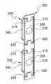
도 1은 본 발명의 일 실시예에 따른 이동통신 단말기의 사이드 버튼 구조의 일측 분해 사시도이다.
도 2는 본 발명의 일 실시예에 따른 이동통신 단말기의 사이드 버튼 구조의 타측 분해 사시도이다.
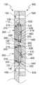
도 3은 본 발명의 일 실시예에 따른 이동통신 단말기의 사이드 버튼 구조의 단면도이다.
도 4는 버튼(200)과 판 스프링(300)의 일측 사시도이다.
도 5는 버튼(200)과 판 스프링(300)의 타측 사시도이다.1 is an exploded perspective view of one side of a side button structure of a mobile communication terminal according to an embodiment of the present invention.
2 is an exploded perspective view of the other side of a side button structure of a mobile communication terminal according to an embodiment of the present invention.
3 is a sectional view of a side button structure of a mobile communication terminal according to an embodiment of the present invention.
4 is a perspective view of one side of the
5 is a perspective view of the other side of the
이하에서는 도면을 참조하여 본 발명의 바람직한 실시예들을 상세히 설명한다. 이하 설명 및 첨부된 도면들에서 실질적으로 동일한 구성요소들은 각각 동일한 부호들로 나타냄으로써 중복 설명을 생략하기로 한다. 또한 본 발명을 설명함에 있어 관련된 공지기능 혹은 구성에 대한 구체적인 설명이 본 발명의 요지를 불필요하게 흐릴 수 있다고 판단되는 경우 그에 대한 상세한 설명은 생략하기로 한다.Hereinafter, preferred embodiments of the present invention will be described in detail with reference to the drawings. In the following description and the accompanying drawings, substantially the same components are denoted by the same reference numerals, and redundant description will be omitted. In the following description of the present invention, a detailed description of known functions and configurations incorporated herein will be omitted when it may make the subject matter of the present invention rather unclear.
본 발명의 실시예에 따른 이동통신 단말기의 사이드 버튼 구조는 압전 소자를 이용한다. 압전 소자란 압전 효과를 이용하는 소자로서, 외력(또는 접촉)을 가함으로써 변형이 생기면 전기 분극이 일어나서 전위차가 생기고, 반대로 전압을 가하면 변형이나 변형력이 생기는 성질을 가지는 소자이다.The side button structure of the mobile communication terminal according to the embodiment of the present invention uses a piezoelectric element. A piezoelectric element is a device using a piezoelectric effect. When a piezoelectric element is deformed by an external force (or contact), electric polarization occurs to generate a potential difference. When a voltage is applied to the piezoelectric element, deformation or stress occurs.
압전 소자를 이용한 버튼은 외력을 감지하여 전기적 신호를 생성함으로써 입력 수단으로 기능할 수 있을 뿐만 아니라, 압전 소자에 전기적 신호를 가하여 진동을 발생시킴으로써 사용자에게 피드백을 줄 수 있는 장점을 가지고 있다.A button using a piezoelectric element not only functions as an input means by generating an electrical signal by sensing an external force, but also has an advantage of giving feedback to a user by generating an oscillation by applying an electrical signal to the piezoelectric element.
도 1 내지 3은 본 발명의 일 실시예에 따른 사이드 버튼 구조의 도면으로서, 도 1은 일측 분해 사시도를, 도 2는 타측 분해 사시도를, 도 3은 단면도를 나타낸다.1 to 3 are views of a side button structure according to an embodiment of the present invention. FIG. 1 is an exploded perspective view of one side, FIG. 2 is an exploded perspective view of the other side, and FIG. 3 is a sectional view.
도 1 내지 3을 참조하면, 본 실시예에 따른 사이드 버튼 구조는, 프레임(100), 버튼(200), 판 스프링(300), 압전 소자(400), 및 지지부재(500)를 포함한다.1 to 3, the side button structure according to the present embodiment includes a
도 4 내지 5는 버튼(200)과 판 스프링(300)만을 별도로 도시한 도면으로, 도 4는 일측 사시도를, 도 5는 타측 사시도를 나타낸다.Figs. 4 to 5 are views showing only the
본 발명의 실시예는 버튼(200)이 두 개인 것을 예로 들어 설명하나, 버튼(200)은 한 개일 수도 있고, 두 개 이상일 수도 있음은 물론이다.It should be understood that the embodiment of the present invention will be described by way of example in which two
프레임(100)은 이동통신 단말기의 하우징 또는 케이스, 혹은 하우징 또는 케이스의 일부일 수 있다. 프레임(100)은 이동통신 단말기의 측면에 해당할 수 있는데, 여기서 이동통신 단말기의 ‘측면’이란 이동통신 단말기의 옆면, 윗면, 혹은 아랫면을 의미한다. 프레임(100)은 메탈 또는 합성수지재일 수 있다.The
프레임(100)은 측면에 버튼공(105)이 형성되어, 버튼공(105)에 버튼(200)이 삽입된다.A
버튼(200)의 외측면은 프레임(100)의 측면과 동일한 높이이거나 프레임(100)의 측면보다 미세하게 돌출될 수 있다. 이렇게 함으로써 사용자로 하여금 버튼(200)이 프레임(100)과 일체화되거나 프레임(100)의 일부인 것처럼 느끼도록 할 수 있다.The outer surface of the
버튼(200)이 프레임(100)에 지지될 수 있도록, 버튼(200)은 내측 양쪽 가장자리에 걸림돌기(210, 220)가 돌출형성되고, 프레임(100) 내측에는 버튼공(200)의 양쪽 가장자리 부분에 버튼(200)의 걸림돌기(210, 220)가 수용되는 제1 걸림홈(110, 120)이 형성될 수 있다. 이러한 걸림돌기(210, 220)와 제1 걸림홈(110, 120)에 의하여 버튼(200)은 프레임(100) 바깥쪽으로 이탈하지 않는다.
버튼(200)은 내측면 중앙 부위에 가압돌기(230)가 형성되고, 가압돌기(230)는 후술할 압전 소자(400)의 일면의 중앙 부위와 닿도록 배치될 수 있다. 따라서 사용자가 버튼(200)에 외력을 가하게 되면 가압돌기(230)를 통하여 외력이 압전 소자(400)에 전달된다. 반대로 압전 소자(400)의 진동이 발생하면 진동은 가압돌기(230)를 통하여 버튼(200)에 전달되고, 버튼(200)을 터치한 사용자는 진동을 느낄 수 있다.The
또한 버튼(200)과 버튼공(105)에서의 방수를 위하여, 버튼(200)에는 버튼공(105)에 대응하는 외주면 둘레에 홈이 형성되고, 방수용 실링과 같은 방수부재(240)가 상기 홈에 수용되는 형태로 구비될 수 있다. 실시예에 따라서는 버튼(200)의 외주면 둘레 뿐 아니라, 버튼공(105)의 내주면 둘레에도 방수부재(240)가 수용되는 홈이 형성될 수 있다.The
압전 소자(400)는 플레이트(410)와, 플레이트(410)의 한 면(또는 양쪽 면)에 부착된 압전체(420)로 이루어진다. 플레이트(410)는 전형적으로 금속제로서, 예컨대 스테인레스 재질일 수 있으며, 압전체(420)보다 큰 면적을 가진다. 압전체(420)는 수정, 전기석(tourmaline), 로셸염(Rochelle salt), 타이타늄산바륨(barium titanate), 인산이수소암모늄(Monoammonium Phosphate), 타타르산에틸렌다이아민 등의 압전성이 뛰어난 재료를 이용하여 제작될 수 있다.The
압전 소자(400)는 제1 및 제2 외부 전극(미도시)을 구비한다. 제1 및 제2 외부 전극은 이동통신 단말기의 회로 장치와 도선 또는 도선이 형성된 연성회로기판을 통하여 연결될 수 있다. 압전 소자(400)가 변형을 일으키면 이동통신 단말기의 회로 장치는 제1 및 제2 외부 전극을 통하여 검출되는 전압을 측정함으로써 외력 또는 접촉을 검출할 수 있다. 반대로, 이동통신 단말기의 회로 장치는 제1 및 제2 외부 전극에 전기적 신호를 인가함으로써 압전 소자(400)에 진동을 일으킬 수도 있다.The
지지부재(500)는 압전 소자(400)의 타면, 즉 압전 소자(400)를 기준으로 버튼(200)의 반대쪽 면에 배치되어, 압전 소자(400)의 양측 가장자리를 지지한다. 지지부재(500)에는 압전 소자(400)의 양측 가장자리(구체적으로는, 플레이트(410)의 양측 가장자리)를 지지하는 지지홈(530, 540)이 형성되고, 압전 소자(400)의 양측 가장자리는 접착제를 이용하여 지지홈(530, 540)에 부착될 수 있다.The
지지부재(500)에는 버튼(200)의 가압돌기(230)에 대응하는 위치에 압전 소자(400)의 타면으로부터 일정 간격 이격되어 압전 소자(400)의 내측으로의 변위를 제한하는 스토퍼돌기(510)가 형성될 수 있다. 여기서 압전 소자(400)의 내측면과 스토퍼돌기(510)와의 간격은 예컨대 10~30μm일 수 있다. 즉, 스토퍼돌기(510)는 압전 소자(400)의 내측으로의 변위를 10~30μm로 제한할 수 있다. 다만 압전 소자(400)의 타면과 스토퍼돌기(510)와의 간격은 압전 소자(400)의 특성, 감지할 압력의 정도 등에 따라 적절한 값으로 정해질 수 있으며, 본 발명은 이에 제한되지 않는다.The
한편, 프레임(100)에는 결합공(150)이 형성되고, 지지부재(500)에는 프레임(100)의 결합공(150)에 대응하는 위치에 관통공(520)이 형성되어, 관통공(520)과 결합공(150)을 가로지르는 결합부재(예컨대, 나사)에 의하여 프레임(100)과 지지부재(500)가 결합될 수 있다.A through
버튼(200)과 압전 소자(400) 사이에 배치되는 판 스프링(300)은 버튼(200)을 탄성 지지한다. 판 스프링(300)은 탄성력이 있는 금속 재질 또는 합성수지재로 이루어질 수 있다. 판 스프링(300)은 내측에서 버튼(200)을 지지함과 동시에, 버튼(200)에 압력이 가해지는 경우에 판 스프링(300)의 복원력에 의하여 버튼(200)에게 바깥쪽 방향으로 탄성력을 제공할 수 있다. 따라서 버튼(200)에 가해진 압력이 해제되면 버튼(200)은 제자리로 돌아가게 된다.The
구체적으로, 판 스프링(300)의 외주면은 걸림돌기(210, 220)를 포함한 버튼(200)의 내측면보다 크고, 그 내부에 버튼(200)의 내측면에 대응하는 구멍(305)이 형성될 수 있다. 예컨대, 구멍(305)은 버튼(200)이 들어갈 수 있도록, (후술할 돌출부(310, 320)를 제외한다면) 버튼(200)의 내측면보다 약간 크게 형성될 수 있다. 그리고 구멍(305)의 내주면 중 걸림돌기(210, 220)에 대응하는 부분에 구멍(305) 안쪽으로 돌출부(310, 320)가 형성되어, 이러한 돌출부(310, 320)가 버튼(200)의 걸림돌기(210, 220)를 탄성 지지할 수 있다. 즉, 판 스프링(300)의 돌출부(310, 320)가 버튼(200)의 걸림돌기(210, 220)를 지지함과 동시에, 버튼(200)에 압력이 가해지면 버튼(200)의 걸림돌기(210, 220)가 판 스프링(300)의 돌출부(310, 320)를 누름으로써 돌출부(310, 320)가 변형이 되며, 이때 돌출부(310, 320)에는 복원력이 발생하게 된다.More specifically, the outer circumferential surface of the
이러한 판 스프링(300)을 수용하기 위하여, 프레임(100)의 내측에는 제1 걸림홈(110, 120) 바깥쪽에 판 스프링(300)의 가장자리가 수용되는 제2 걸림홈(130, 140)이 형성될 수 있다.In order to accommodate the
상기된 본 발명에 의하면, 이동통신 단말기의 사이드 버튼이 이동통신 단말기의 측면 프레임과 일체화되거나 일부인 것처럼 느껴지도록 구현할 수 있으며, 기존의 돔 스위치 방식이나 택트 스위치 방식과 같은 버튼의 “누름” 대신에 압력 또는 터치를 통하여 조작 가능한 사이드 버튼을 구현할 수 있다.According to the present invention, the side button of the mobile communication terminal can be integrated with the side frame of the mobile communication terminal or can be realized as a part of the side frame. In addition, Or a side button that can be operated through a touch.
게다가, 이동통신 단말기의 사이드 버튼이 입력 수단으로 기능할 수 있을 뿐만 아니라, 압전 소자에 전기적 신호를 가하여 진동을 발생시킴으로써 사용자에게 피드백을 주는 수단으로도 기능할 수 있다.In addition, not only the side button of the mobile communication terminal can function as the input means, but also can function as a means for providing feedback to the user by generating an oscillation by applying an electric signal to the piezoelectric element.
또한, 가격이 저렴한 압전 소자를 사용하므로 비용 면에서 유리하고, 구조가 간단하고 조립 공정이 단순하며, 소형화가 용이하여 이동통신 단말기의 슬림화에 기여할 수 있는 장점이 있다.In addition, since the use of the inexpensive piezoelectric element is advantageous in terms of cost, the structure is simple, the assembling process is simple, and the miniaturization is easy, thereby contributing to slimming down the mobile communication terminal.
이제까지 본 발명에 대하여 그 바람직한 실시예들을 중심으로 살펴보았다. 본 발명이 속하는 기술 분야에서 통상의 지식을 가진 자는 본 발명이 본 발명의 본질적인 특성에서 벗어나지 않는 범위에서 변형된 형태로 구현될 수 있음을 이해할 수 있을 것이다. 그러므로 개시된 실시예들은 한정적인 관점이 아니라 설명적인 관점에서 고려되어야 한다. 본 발명의 범위는 전술한 설명이 아니라 특허청구범위에 나타나 있으며, 그와 동등한 범위 내에 있는 모든 차이점은 본 발명에 포함된 것으로 해석되어야 할 것이다.The present invention has been described with reference to the preferred embodiments. It will be understood by those skilled in the art that various changes in form and details may be made therein without departing from the spirit and scope of the invention as defined by the appended claims. Therefore, the disclosed embodiments should be considered in an illustrative rather than a restrictive sense. The scope of the present invention is defined by the appended claims rather than by the foregoing description, and all differences within the scope of equivalents thereof should be construed as being included in the present invention.
Claims (15)
Translated fromKorean상기 버튼공에 삽입되며, 내측면에 가압돌기가 형성되는 버튼;
일면이 상기 가압돌기에 닿아 있는 압전 소자; 및
상기 압전 소자의 타면 측에 배치되고 상기 압전 소자의 양측 가장자리를 지지하는 지지부재를 포함하는 이동통신 단말기의 사이드 버튼 구조.A frame formed with a button ball;
A button inserted into the button hole and having a pressing projection formed on an inner surface thereof;
A piezoelectric element whose one surface is in contact with the pressing projection; And
And a support member disposed on the other surface side of the piezoelectric element and supporting both side edges of the piezoelectric element.
상기 지지부재는, 상기 가압돌기에 대응하는 위치에 상기 압전 소자의 타면으로부터 일정 간격 이격되어 상기 압전 소자의 변위를 제한하는 스토퍼돌기가 형성되는 이동통신 단말기의 사이드 버튼 구조.The method according to claim 1,
Wherein the support member has a stopper protrusion that is spaced apart from the other surface of the piezoelectric element at a position corresponding to the pressing protrusion to limit displacement of the piezoelectric element.
상기 버튼은 내측 양쪽 가장자리에 걸림돌기가 돌출형성되고,
상기 프레임 내측에 상기 걸림돌기가 수용되는 제1 걸림홈이 형성되는 이동통신 단말기의 사이드 버튼 구조.The method according to claim 1,
Wherein the button has protruding engagement protrusions formed on both inner side edges thereof,
And a first latching groove for receiving the latching protrusion is formed inside the frame.
상기 버튼과 상기 압전 소자 사이에 구비되어 상기 버튼을 탄성 지지하는 판 스프링을 더 포함하는 이동통신 단말기의 사이드 버튼 구조.The method of claim 3,
And a leaf spring provided between the button and the piezoelectric element to elastically support the button.
상기 판 스프링은 상기 걸림돌기를 탄성 지지하는 이동통신 단말기의 사이드 버튼 구조.5. The method of claim 4,
And the leaf spring elastically supports the locking projection.
상기 판 스프링은 상기 버튼의 내측면에 대응하는 구멍이 형성되고, 상기 구멍의 내주면 중 상기 걸림돌기에 대응하는 부분에 상기 구멍 안쪽으로 돌출부가 형성되어 상기 돌출부가 상기 걸림돌기를 탄성 지지하는 이동통신 단말기의 사이드 버튼 구조.6. The method of claim 5,
Wherein the plate spring has a hole corresponding to an inner surface of the button, and a protruding portion is formed in a portion of the inner circumferential surface of the hole corresponding to the locking protrusion, the protruding portion elastically supporting the locking protrusion Side button structure.
상기 프레임 내측에 상기 판 스프링의 가장자리가 수용되는 제2 걸림홈이 형성되는 이동통신 단말기의 사이드 버튼 구조.5. The method of claim 4,
And a second latching groove for receiving the edge of the leaf spring is formed inside the frame.
상기 버튼은 상기 버튼공에 대응하는 외주면 둘레에 방수부재가 구비되는 이동통신 단말기의 사이드 버튼 구조.The method according to claim 1,
Wherein the button is provided with a waterproofing member around an outer peripheral surface corresponding to the button hole.
상기 버튼공에 삽입되며, 내측면에 가압돌기가 형성되는 버튼;
일면이 상기 가압돌기에 닿아 있는 압전 소자; 및
상기 버튼과 상기 압전 소자 사이에 구비되어 상기 버튼을 탄성 지지하는 판 스프링을 포함하는 이동통신 단말기의 사이드 버튼 구조.A frame formed with a button ball;
A button inserted into the button hole and having a pressing projection formed on an inner surface thereof;
A piezoelectric element whose one surface is in contact with the pressing projection; And
And a leaf spring provided between the button and the piezoelectric element to elastically support the button.
상기 버튼은 내측 양쪽 가장자리에 걸림돌기가 돌출형성되고,
상기 프레임 내측에 상기 걸림돌기가 수용되는 제1 걸림홈이 형성되는 이동통신 단말기의 사이드 버튼 구조.10. The method of claim 9,
Wherein the button has protruding engagement protrusions formed on both inner side edges thereof,
And a first latching groove for receiving the latching protrusion is formed inside the frame.
상기 판 스프링은 상기 걸림돌기를 탄성 지지하는 이동통신 단말기의 사이드 버튼 구조.11. The method of claim 10,
And the leaf spring elastically supports the locking projection.
상기 판 스프링은 상기 버튼의 내측면에 대응하는 구멍이 형성되고, 상기 구멍의 내주면 중 상기 걸림돌기에 대응하는 부분에 상기 구멍 안쪽으로 돌출부가 형성되어 상기 돌출부가 상기 걸림돌기를 탄성 지지하는 이동통신 단말기의 사이드 버튼 구조.12. The method of claim 11,
Wherein the plate spring has a hole corresponding to an inner surface of the button, and a protruding portion is formed in a portion of the inner circumferential surface of the hole corresponding to the locking protrusion, the protruding portion elastically supporting the locking protrusion Side button structure.
상기 프레임 내측에 상기 판 스프링의 가장자리가 형성되는 제2 걸림홈이 형성되는 이동통신 단말기의 사이드 버튼 구조.11. The method of claim 10,
And a second latching groove formed at an edge of the leaf spring is formed inside the frame.
상기 압전 소자의 타면 측에 배치되고, 상기 압전 소자의 양측 가장자리를 지지하며, 상기 가압돌기에 대응하는 위치에 상기 압전 소자의 타면으로부터 일정 간격 이격되어 상기 압전 소자의 변위를 제한하는 스토퍼돌기가 형성되는 지지부재를 더 포함하는 이동통신 단말기의 사이드 버튼 구조.10. The method of claim 9,
A stopper protrusion which is disposed on the other surface side of the piezoelectric element and which supports both side edges of the piezoelectric element and which is spaced from the other surface of the piezoelectric element at a position corresponding to the pressing protrusion to limit displacement of the piezoelectric element The side button structure of the mobile communication terminal.
상기 버튼은 상기 버튼공에 대응하는 외주면 둘레에 방수부재가 구비되는 이동통신 단말기의 사이드 버튼 구조.10. The method of claim 9,
Wherein the button is provided with a waterproofing member around an outer peripheral surface corresponding to the button hole.
Priority Applications (4)
| Application Number | Priority Date | Filing Date | Title |
|---|---|---|---|
| KR1020160019613AKR20170097925A (en) | 2016-02-19 | 2016-02-19 | Side button structure of mobile communication terminal |
| PCT/KR2017/001698WO2017142320A1 (en) | 2016-02-19 | 2017-02-16 | Mobile communication terminal side button structure |
| CN201780012211.9ACN108701569A (en) | 2016-02-19 | 2017-02-16 | The side press-button structure of mobile communication terminal |
| US16/077,628US20190035572A1 (en) | 2016-02-19 | 2017-02-16 | Mobile Communication Terminal Side Button Structure |
Applications Claiming Priority (1)
| Application Number | Priority Date | Filing Date | Title |
|---|---|---|---|
| KR1020160019613AKR20170097925A (en) | 2016-02-19 | 2016-02-19 | Side button structure of mobile communication terminal |
Publications (1)
| Publication Number | Publication Date |
|---|---|
| KR20170097925Atrue KR20170097925A (en) | 2017-08-29 |
Family
ID=59626166
Family Applications (1)
| Application Number | Title | Priority Date | Filing Date |
|---|---|---|---|
| KR1020160019613ACeasedKR20170097925A (en) | 2016-02-19 | 2016-02-19 | Side button structure of mobile communication terminal |
Country Status (4)
| Country | Link |
|---|---|
| US (1) | US20190035572A1 (en) |
| KR (1) | KR20170097925A (en) |
| CN (1) | CN108701569A (en) |
| WO (1) | WO2017142320A1 (en) |
Cited By (2)
| Publication number | Priority date | Publication date | Assignee | Title |
|---|---|---|---|---|
| KR102029287B1 (en) | 2019-05-23 | 2019-10-10 | (주)에이치케이티 | Side button for portable device |
| KR20250057187A (en)* | 2023-10-19 | 2025-04-29 | 주식회사 비쥬드림 | Switch using piezoelectric element |
Families Citing this family (1)
| Publication number | Priority date | Publication date | Assignee | Title |
|---|---|---|---|---|
| KR102345111B1 (en)* | 2020-04-24 | 2021-12-30 | 삼성전기주식회사 | Force sensor module and electronic device with the same |
Family Cites Families (11)
| Publication number | Priority date | Publication date | Assignee | Title |
|---|---|---|---|---|
| CN2674623Y (en)* | 2004-01-16 | 2005-01-26 | 顺德市顺达电脑厂有限公司 | Panel with keys |
| KR20070014311A (en)* | 2005-07-28 | 2007-02-01 | 주식회사 팬택 | Side Button Structure of Mobile Communication Terminal |
| JP4767125B2 (en)* | 2006-08-09 | 2011-09-07 | 三井金属アクト株式会社 | Latch release operation device |
| CN101459007B (en)* | 2007-12-14 | 2010-11-10 | 鸿富锦精密工业(深圳)有限公司 | Key-press module group |
| US8362381B2 (en)* | 2008-03-06 | 2013-01-29 | Nec Corporation | Switch mechanism and electronic device |
| US8030584B2 (en)* | 2008-12-08 | 2011-10-04 | Hanbit Precision Co., Ltd. | Side key module for mobile communication terminal |
| TWI373056B (en)* | 2009-08-14 | 2012-09-21 | Wistron Corp | Illumination button, illumination switch assembly, and button assembly for rapidly assembling button cap |
| KR101610206B1 (en)* | 2009-08-26 | 2016-04-07 | 엘지전자 주식회사 | Portable terminal |
| CN102044364A (en)* | 2009-10-23 | 2011-05-04 | 鸿富锦精密工业(深圳)有限公司 | Power button module and electronic device using same |
| KR20120003764A (en)* | 2010-07-05 | 2012-01-11 | 엘지전자 주식회사 | Touch sensor and touch recognition method |
| KR101107015B1 (en)* | 2010-09-02 | 2012-01-25 | (주)블루버드 소프트 | Mobile terminal and manufacturing method thereof |
- 2016
- 2016-02-19KRKR1020160019613Apatent/KR20170097925A/ennot_activeCeased
- 2017
- 2017-02-16CNCN201780012211.9Apatent/CN108701569A/ennot_activeWithdrawn
- 2017-02-16WOPCT/KR2017/001698patent/WO2017142320A1/ennot_activeCeased
- 2017-02-16USUS16/077,628patent/US20190035572A1/ennot_activeAbandoned
Cited By (2)
| Publication number | Priority date | Publication date | Assignee | Title |
|---|---|---|---|---|
| KR102029287B1 (en) | 2019-05-23 | 2019-10-10 | (주)에이치케이티 | Side button for portable device |
| KR20250057187A (en)* | 2023-10-19 | 2025-04-29 | 주식회사 비쥬드림 | Switch using piezoelectric element |
Also Published As
| Publication number | Publication date |
|---|---|
| US20190035572A1 (en) | 2019-01-31 |
| WO2017142320A1 (en) | 2017-08-24 |
| CN108701569A (en) | 2018-10-23 |
Similar Documents
| Publication | Publication Date | Title |
|---|---|---|
| US6373265B1 (en) | Electrostatic capacitive touch sensor | |
| CN105072220B (en) | Electronic equipment and key-press mounting structure | |
| US20160381820A1 (en) | Electronic device having a waterproof structure | |
| US20170140883A1 (en) | Electronic apparatus having a switch device | |
| GB2464584A (en) | A touch module connected to a housing and disposed above a swich module | |
| CN104618551B (en) | Side button installation structure and electronic equipment | |
| US6064141A (en) | Piezoelectric switch | |
| JP2011243476A (en) | Push switch | |
| US8098494B2 (en) | Electronic device | |
| US9337883B1 (en) | Protection case for mobile communication device | |
| KR20170097925A (en) | Side button structure of mobile communication terminal | |
| KR101620043B1 (en) | Apparatus for connecting side key of mobile terminal | |
| US9257244B2 (en) | Electronic device with power switch | |
| US20200128311A1 (en) | Waterproof speaker device | |
| JP2008059210A (en) | Input device | |
| WO2019150960A1 (en) | Housing-cum-switch, and input device | |
| CN107452533B (en) | Switch assembly, push switch and electronic device including the same | |
| CN211506414U (en) | Piezoelectric module and electronic equipment | |
| WO2016181610A1 (en) | Electronic instrument | |
| CN115104169A (en) | Electronic equipment | |
| US8243457B2 (en) | Electronic component mounting structure, electronic device and manufacturing method of an electronic device | |
| JP2007165101A (en) | Electronic equipment equipped with antistatic function | |
| US11618057B2 (en) | Localized haptic feedback in electronic devices using pressure-sensitive adhesive and piezoelectric haptic actuators | |
| US20250166942A1 (en) | Piezoelectric button assembly and electronic device | |
| KR20140144834A (en) | Capacitive touch sensing apparatus |
Legal Events
| Date | Code | Title | Description |
|---|---|---|---|
| PA0109 | Patent application | Patent event code:PA01091R01D Comment text:Patent Application Patent event date:20160219 | |
| PG1501 | Laying open of application | ||
| PA0201 | Request for examination | Patent event code:PA02012R01D Patent event date:20191001 Comment text:Request for Examination of Application Patent event code:PA02011R01I Patent event date:20160219 Comment text:Patent Application | |
| E902 | Notification of reason for refusal | ||
| PE0902 | Notice of grounds for rejection | Comment text:Notification of reason for refusal Patent event date:20201029 Patent event code:PE09021S01D | |
| E601 | Decision to refuse application | ||
| PE0601 | Decision on rejection of patent | Patent event date:20210118 Comment text:Decision to Refuse Application Patent event code:PE06012S01D Patent event date:20201029 Comment text:Notification of reason for refusal Patent event code:PE06011S01I |