KR20170097219A - Electric Driving Device and Electric Power Steering Device - Google Patents
Electric Driving Device and Electric Power Steering DeviceDownload PDFInfo
- Publication number
- KR20170097219A KR20170097219AKR1020177021937AKR20177021937AKR20170097219AKR 20170097219 AKR20170097219 AKR 20170097219AKR 1020177021937 AKR1020177021937 AKR 1020177021937AKR 20177021937 AKR20177021937 AKR 20177021937AKR 20170097219 AKR20170097219 AKR 20170097219A
- Authority
- KR
- South Korea
- Prior art keywords
- power supply
- circuit portion
- metal substrate
- connector
- power
- Prior art date
- Legal status (The legal status is an assumption and is not a legal conclusion. Google has not performed a legal analysis and makes no representation as to the accuracy of the status listed.)
- Granted
Links
Images


Classifications
- H—ELECTRICITY
- H02—GENERATION; CONVERSION OR DISTRIBUTION OF ELECTRIC POWER
- H02K—DYNAMO-ELECTRIC MACHINES
- H02K5/00—Casings; Enclosures; Supports
- H02K5/04—Casings or enclosures characterised by the shape, form or construction thereof
- H02K5/22—Auxiliary parts of casings not covered by groups H02K5/06-H02K5/20, e.g. shaped to form connection boxes or terminal boxes
- H02K5/225—Terminal boxes or connection arrangements
- H—ELECTRICITY
- H02—GENERATION; CONVERSION OR DISTRIBUTION OF ELECTRIC POWER
- H02K—DYNAMO-ELECTRIC MACHINES
- H02K11/00—Structural association of dynamo-electric machines with electric components or with devices for shielding, monitoring or protection
- H02K11/30—Structural association with control circuits or drive circuits
- B—PERFORMING OPERATIONS; TRANSPORTING
- B60—VEHICLES IN GENERAL
- B60R—VEHICLES, VEHICLE FITTINGS, OR VEHICLE PARTS, NOT OTHERWISE PROVIDED FOR
- B60R16/00—Electric or fluid circuits specially adapted for vehicles and not otherwise provided for; Arrangement of elements of electric or fluid circuits specially adapted for vehicles and not otherwise provided for
- B60R16/02—Electric or fluid circuits specially adapted for vehicles and not otherwise provided for; Arrangement of elements of electric or fluid circuits specially adapted for vehicles and not otherwise provided for electric constitutive elements
- B60R16/023—Electric or fluid circuits specially adapted for vehicles and not otherwise provided for; Arrangement of elements of electric or fluid circuits specially adapted for vehicles and not otherwise provided for electric constitutive elements for transmission of signals between vehicle parts or subsystems
- B—PERFORMING OPERATIONS; TRANSPORTING
- B62—LAND VEHICLES FOR TRAVELLING OTHERWISE THAN ON RAILS
- B62D—MOTOR VEHICLES; TRAILERS
- B62D5/00—Power-assisted or power-driven steering
- B62D5/04—Power-assisted or power-driven steering electrical, e.g. using an electric servo-motor connected to, or forming part of, the steering gear
- B62D5/0403—Power-assisted or power-driven steering electrical, e.g. using an electric servo-motor connected to, or forming part of, the steering gear characterised by constructional features, e.g. common housing for motor and gear box
- B62D5/0406—Power-assisted or power-driven steering electrical, e.g. using an electric servo-motor connected to, or forming part of, the steering gear characterised by constructional features, e.g. common housing for motor and gear box including housing for electronic control unit
- B—PERFORMING OPERATIONS; TRANSPORTING
- B62—LAND VEHICLES FOR TRAVELLING OTHERWISE THAN ON RAILS
- B62D—MOTOR VEHICLES; TRAILERS
- B62D5/00—Power-assisted or power-driven steering
- B62D5/04—Power-assisted or power-driven steering electrical, e.g. using an electric servo-motor connected to, or forming part of, the steering gear
- B62D5/0457—Power-assisted or power-driven steering electrical, e.g. using an electric servo-motor connected to, or forming part of, the steering gear characterised by control features of the drive means as such
- B62D5/046—Controlling the motor
- H—ELECTRICITY
- H02—GENERATION; CONVERSION OR DISTRIBUTION OF ELECTRIC POWER
- H02K—DYNAMO-ELECTRIC MACHINES
- H02K11/00—Structural association of dynamo-electric machines with electric components or with devices for shielding, monitoring or protection
- H02K11/30—Structural association with control circuits or drive circuits
- H02K11/33—Drive circuits, e.g. power electronics
- H—ELECTRICITY
- H02—GENERATION; CONVERSION OR DISTRIBUTION OF ELECTRIC POWER
- H02K—DYNAMO-ELECTRIC MACHINES
- H02K5/00—Casings; Enclosures; Supports
- H02K5/02—Casings or enclosures characterised by the material thereof
- H—ELECTRICITY
- H02—GENERATION; CONVERSION OR DISTRIBUTION OF ELECTRIC POWER
- H02K—DYNAMO-ELECTRIC MACHINES
- H02K5/00—Casings; Enclosures; Supports
- H02K5/04—Casings or enclosures characterised by the shape, form or construction thereof
- H02K5/10—Casings or enclosures characterised by the shape, form or construction thereof with arrangements for protection from ingress, e.g. water or fingers
Landscapes
- Engineering & Computer Science (AREA)
- Power Engineering (AREA)
- Mechanical Engineering (AREA)
- Chemical & Material Sciences (AREA)
- Combustion & Propulsion (AREA)
- Transportation (AREA)
- Microelectronics & Electronic Packaging (AREA)
- Power Steering Mechanism (AREA)
- Combinations Of Printed Boards (AREA)
- Motor Or Generator Frames (AREA)
Abstract
Translated fromKoreanDescription
Translated fromKorean본 발명은 전동 구동 장치 및 전동 파워 스티어링 장치에 관한 것으로, 특히 전자 제어 장치를 내장한 전동 구동 장치 및 전동 파워 스티어링 장치에 관한 것이다.BACKGROUND OF THE INVENTION 1. Field of the Invention The present invention relates to an electric driving device and an electric power steering device, and more particularly to an electric driving device and an electric power steering device having an electronic control device.
일반적인 산업 기계 분야에서는, 전동 모터에 의해서 기계계 제어 요소를 구동하고 있는데, 최근에는 전동 모터의 회전 속도나 회전 토크를 제어하는 반도체 소자 등으로 이루어지는 전자 제어 장치를 전동 모터에 일체적으로 내장하는, 소위 기전(機電) 일체형의 전동 구동 장치가 채용되기 시작하고 있다.BACKGROUND ART [0002] In general industrial machinery fields, mechanical control elements are driven by an electric motor. In recent years, electronic control devices, such as semiconductor elements for controlling the rotational speed and rotational torque of an electric motor, A so-called electromechanical (electric) one-piece type electric driving apparatus is beginning to be adopted.
기전 일체형의 전동 구동 장치의 예로서, 예컨대 자동차의 전동 파워 스티어링 장치에 있어서는, 운전자가 스티어링 휠을 조작함으로써 회동하는 스티어링 샤프트의 회동 방향과 회동 토크를 검출하고, 이 검출치에 기초하여 스티어링 샤프트의 회동 방향과 동일한 방향으로 회동하도록 전동 모터를 구동하여, 조타 어시스트 토크를 발생시키도록 구성되어 있다. 이 전동 모터를 제어하기 위해서, 전자 제어 장치(ECU: ElectronicControl Unit)가 파워 스티어링 장치에 설치되어 있다.[0003] For example, in an electric power steering apparatus of an automobile, an example of a mechanically integrated electric drive apparatus includes an electric power steering apparatus that detects a turning direction and a turning torque of a steering shaft rotated by a driver by operating a steering wheel, And drives the electric motor so as to rotate in the same direction as the rotating direction, thereby generating the steering assist torque. In order to control the electric motor, an electronic control unit (ECU) is provided in the power steering device.
종래의 전동 파워 스티어링 장치로서는, 예컨대, 일본 특허공개 2013-60119호 공보(특허문헌 1)에 기재된 것이 알려져 있다. 특허문헌 1에는, 전동 모터와 전자 제어 장치에 의해 구성된 전동 파워 스티어링 장치가 기재되어 있다. 그리고, 전동 모터는, 알루미늄 합금 등으로 만들어진 통부를 갖는 모터 하우징에 수납되고, 전자 제어 장치는, 모터 하우징의 축 방향의 출력축과는 반대쪽에 배치된 ECU 하우징에 수납되어 있다. ECU 하우징의 내부에 수납되는 전자 제어 장치는, 전원 회로부, 전동 모터를 구동 제어하는 MOSFET 혹은 IGBT 등과 같은 파워 스위칭 소자를 갖는 전력 변환 회로부와, 파워 스위칭 소자를 제어하는 제어 회로부를 구비하고, 파워 스위칭 소자의 출력 단자와 전동 모터의 입력 단자는 버스 바를 통해 전기적으로 접속되어 있다.As a conventional electric power steering apparatus, for example, Japanese Patent Laid-Open Publication No. 2013-60119 (Patent Document 1) is known. Patent Document 1 discloses an electric power steering device configured by an electric motor and an electronic control device. The electric motor is housed in a motor housing having a cylinder portion made of an aluminum alloy or the like, and the electronic control device is housed in an ECU housing disposed on the opposite side to the axial output shaft of the motor housing. The electronic control device housed inside the ECU housing includes a power circuit portion, a power conversion circuit portion having a power switching device such as a MOSFET or an IGBT for driving and controlling the electric motor, and a control circuit portion for controlling the power switching device, The output terminal of the element and the input terminal of the electric motor are electrically connected through a bus bar.
그리고, ECU 하우징에 수납된 전자 제어 장치에는, 합성수지로 만들어진 커넥터 단자 조립체를 통해 전원으로부터 전력이 공급되고, 또한 검출 센서류로부터 운전 상태 등의 검출 신호가 공급되고 있다. 커넥터 단자 조립체는 덮개로서 기능하고 있어, ECU 하우징에 형성된 개구부를 막도록 하여 전자 제어 장치와 접속되며, 또한 고정 볼트에 의해서 ECU 하우징의 외표면에 고정되어 있다.Electric power is supplied from a power source through a connector terminal assembly made of a synthetic resin to an electronic control unit housed in the ECU housing, and a detection signal such as an operating state is supplied from the detection sensors. The connector terminal assembly functions as a lid and is connected to the electronic control unit so as to close an opening formed in the ECU housing, and is fixed to the outer surface of the ECU housing by a fixing bolt.
또한, 이 밖에 전자 제어 장치를 일체화한 전동 구동 장치로서는, 전동 브레이크나 각종 유압 제어용의 전동 유압 제어기 등이 알려져 있다.In addition, as an electric driving device in which an electronic control device is integrated, there is known an electric brake and an electric hydraulic pressure controller for controlling various kinds of hydraulic pressure.
그런데, 특허문헌 1에 기재되어 있는 전동 파워 스티어링 장치는 자동차의 엔진룸 내에 배치되므로, 소형으로 구성될 필요가 있다. 특히 최근에는 자동차의 엔진룸 내부는, 배기가스 대책 기기나 안전 대책 기기 등의 보조 기계류가 많이 설치되는 경향이 있어, 전동 파워 스티어링 장치를 포함하여 각종 보조 기계류는 가능한 한 소형화하거나 부품 점수를 저감할 것이 요구되고 있다.However, since the electric power steering apparatus described in Patent Document 1 is disposed in the engine room of an automobile, it needs to be made compact. Especially in recent years, a lot of auxiliary machinery such as an exhaust gas countermeasure device and a safety countermeasure tends to be installed inside an engine room of an automobile, so that various auxiliary machinery including an electric power steering device are miniaturized as much as possible, .
그리고, 특허문헌 1에 있는 것과 같은 구성의 전동 파워 스티어링 장치에 있어서는, 전원 회로부, 전력 변환 회로부 및 제어 회로부가 2장의 기판에 실장되어 있다. 이 때문에, 전동 모터를 제어하기 위해 필요한 전기 부품의 부품 점수는 대략 정해져 있기 때문에, 2장의 기판에 이들 부품 점수의 전기 부품을 실장하면, 전자 제어 장치를 수납하고 있는 ECU 하우징이 자연히 반경 방향으로 커진다. 전동 파워 스티어링 장치는 그 구조상에 있어서 길이 방향으로는 축 길이의 제한은 비교적 적고, 반경 방향의 대형화가 제한되는 경향이 있다.In the electric power steering apparatus configured as in Patent Document 1, the power supply circuit section, the power conversion circuit section, and the control circuit section are mounted on two boards. Because of this, the number of parts of the electric parts necessary for controlling the electric motor is roughly determined, so that when the electric parts of these parts are mounted on the two boards, the ECU housing accommodating the electronic control device naturally becomes large in the radial direction . The structure of the electric power steering device tends to be limited in the axial length in the longitudinal direction and to be limited in the radial size.
따라서, 하우징을 반경 방향으로 소형화할 것이 요청되는 것이 현재 실정이다.Therefore, it is currently desired to reduce the size of the housing in the radial direction.
이 때문에, 직경 방향으로 소형화하기 위해서 전원 회로부, 전력 변환 회로부 및 제어 회로부를 개별로 3 분할하는 구성이 유효하다. 이에 따르면, 전동 모터를 제어하기 위해 필요한 전기 부품을 3 분할하기 때문에, 2 분할하는 것보다도 기판의 면적을 작게 하여 반경 방향으로 소형화할 수 있게 된다.Therefore, in order to reduce the size in the radial direction, it is effective to divide the power supply circuit portion, the power conversion circuit portion, and the control circuit portion into three. According to this, since the electric parts required for controlling the electric motor are divided into three parts, the area of the board can be made smaller than that of the electric parts divided into two parts, and the electric parts can be downsized in the radial direction.
그러나, 이 3 분할된 각 기판에 전력이나 제어 신호 등을 공급하기 위해서는, 많은 중계 커넥터를 사용하는 복잡한 커넥터 배선부의 구성이 필요하게 되어, 부품 점수가 증가한다는 과제나 소형화의 장해가 되는 과제가 있다. 나아가서는 커넥터 배선부의 구성이 복잡하기 때문에, 조립 공수가 늘어남으로 인한 제품 단가의 상승과 같은 과제도 있다.However, in order to supply electric power, control signals, and the like to each of the three divided substrates, it is necessary to construct a complicated connector wiring portion using a large number of relay connectors, which poses a problem of increasing the number of parts and an obstacle of miniaturization . Furthermore, since the configuration of the connector wiring portion is complicated, there is also a problem such as an increase in the product unit price due to an increase in the number of assembly operations.
본 발명의 목적은, 전자 제어 장치가 수납되는 하우징이 반경 방향으로 대형화되는 것을 억제함과 더불어, 가능한 한 중계 커넥터를 적게 하는 간단한 구성의 커넥터 단자 조립체에 의해서 전원 회로부, 전력 변환 회로부 및 제어 회로부에 전력이나 제어 신호를 공급할 수 있는 신규의 전동 구동 장치 및 전동 파워 스티어링 장치를 제공하는 데에 있다.SUMMARY OF THE INVENTION An object of the present invention is to provide a connector terminal assembly having a simple structure in which a housing accommodating an electronic control device is prevented from being enlarged in a radial direction and a relay connector is made as small as possible, And to provide a new electric driving device and an electric power steering device capable of supplying electric power and control signals.
본 발명의 특징은, 전자 제어 조립체를, 전원의 생성을 주된 기능으로 하는 금속 기판에 실장되는 전원 회로부와, 전동 모터의 구동을 주된 기능으로 하는 금속 기판에 실장되는 전력 변환 회로부와, 전력 변환 회로부의 제어를 주된 기능으로 하는 수지 기판에 실장되는 제어 회로부로 분할함과 함께, 적어도, 전원 회로부에서 전력 변환 회로부 및 제어 회로부로 전력을 공급하는 전력 공급 커넥터 배선부와, 제어 회로부의 입출력 신호를 전송하는 신호 전송 커넥터 배선부를 합성수지로 이루어지는 커넥터 단자 조립체에 매설함과 더불어, 커넥터 단자 조립체로부터 노출되는 전력 공급 커넥터 배선부 및 신호 전송 커넥터 배선부의 커넥터 단자를, 대응하는 전원 회로부, 전력 변환 회로부 및 제어 회로부의 커넥터에 직접적으로 접속하는 데에 있다.A feature of the present invention resides in that the electronic control assembly includes a power supply circuit portion mounted on a metal substrate having a main function of generating power, a power conversion circuit portion mounted on a metal substrate having a main function of driving the electric motor, And a control circuit portion mounted on a resin substrate having a main function of controlling the power supply circuit portion and the control circuit portion, and includes at least a power supply circuit wiring portion for supplying power from the power supply circuit portion to the power conversion circuit portion and the control circuit portion, The power supply connector wiring portion exposed from the connector terminal assembly and the connector terminal of the signal transmission connector wiring portion are connected to the corresponding power supply circuit portion, the power conversion circuit portion, and the control circuit portion In order to directly connect the connector to the connector.
본 발명에 따르면, 전자 제어 장치를 구성하는 전기 부품을 기능 별로 3개의 기판에 실장하여 기판의 반경 방향의 크기를 축소할 수 있음과 더불어, 각 회로부를 접속하는 커넥터 배선부를 합성수지로 이루어지는 커넥터 단자 조립체에 집합하여 대응하는 회로부에 직접적으로 접속하기 때문에, 커넥터 단자 조립체의 부품 점수를 저감하여 구성이 간단하게 되는 효과를 발휘할 수 있다.According to the present invention, it is possible to reduce the size of the board in the radial direction by mounting the electric parts constituting the electronic control device on three boards for each function, and in addition, the connector wiring part for connecting the respective circuit parts can be connected to the connector terminal assembly The number of parts of the connector terminal assembly can be reduced and the effect of simplifying the structure can be exhibited.
도 1은 본 발명이 적용되는 일례로서의 조타 장치의 전체 사시도이다.
도 2는 기전 일체형의 전동 구동 장치로서의 전동 파워 스티어링 장치의 전체 사시도이다.
도 3은 본 발명의 일실시형태가 되는 전동 파워 스티어링 장치의 분해 사시도이다.
도 4는 도 3에 도시하는 전원 회로부의 사시도이다.
도 5는 도 3에 도시하는 전력 변환 회로부의 사시도이다.
도 6은 도 3에 도시하는 제어 회로부의 사시도이다.
도 7은 도 3에 도시하는 커넥터 단자를 갖춘 덮개를 비스듬히 아래쪽에서 본 사시도이다.
도 8은 도 3에 도시하는 A-A면 방향에서 덮개를 본 평면도이다.
도 9는 도 8의 B-B면에서 본 전동 파워 스티어링 장치의 단면을 도시하는 단면도이다. 단, 전동 모터 부분은 생략하고 있다.
도 10은 도 8의 C-C면에서 본 전동 파워 스티어링 장치의 단면을 도시하는 단면도이다. 단, 전동 모터 부분은 생략하고 있다.
도 11은 도 8의 D-D면에서 본 전동 파워 스티어링 장치의 단면을 도시하는 단면도이다. 단, 전동 모터 부분은 생략하고 있다.1 is a whole perspective view of a steering apparatus as an example to which the present invention is applied.
2 is an overall perspective view of an electric power steering apparatus as an electric drive system of a mechanism-integrated type.
3 is an exploded perspective view of an electric power steering apparatus according to an embodiment of the present invention.
Fig. 4 is a perspective view of the power supply circuit portion shown in Fig. 3. Fig.
5 is a perspective view of the power conversion circuit portion shown in Fig.
6 is a perspective view of the control circuit portion shown in Fig.
Fig. 7 is a perspective view of the lid having the connector terminal shown in Fig. 3 viewed diagonally from below. Fig.
8 is a plan view of the lid in the AA plane direction shown in Fig.
Fig. 9 is a sectional view showing a section of the electric power steering apparatus viewed from the BB side in Fig. 8; Fig. However, the electric motor portion is omitted.
10 is a cross-sectional view showing a section of the electric power steering apparatus viewed from the CC side in Fig. However, the electric motor portion is omitted.
Fig. 11 is a sectional view showing a section of the electric power steering apparatus viewed from the DD side in Fig. 8; Fig. However, the electric motor portion is omitted.
이하, 본 발명의 실시형태에 관해서 도면을 이용하여 상세히 설명하지만, 본 발명은 이하의 실시형태에 한정되지 않으며, 본 발명이 기술적인 개념 내에서 다양한 변형예나 응용예도 그 범위에 포함하는 것이다.Hereinafter, embodiments of the present invention will be described in detail with reference to the drawings. However, the present invention is not limited to the following embodiments, and various modifications and applications within the technical concept of the present invention are included in the scope of the present invention.
본 발명의 실시형태를 설명하기 전에 본 발명이 적용되는 일례로서의 조타 장치의 구성 및 기전 일체형 전동 구동 장치로서의 전동 파워 스티어링 장치의 구성에 관해서 도 1, 도 2를 이용하여 간단히 설명한다.Before describing an embodiment of the present invention, a configuration of a steering apparatus and an electric power steering apparatus as a mechanism-integrated type electric drive apparatus as an example to which the present invention is applied will be briefly described with reference to Figs. 1 and 2. Fig.
우선, 자동차의 전륜을 조타하기 위한 조타 장치에 관해서 설명한다. 조타 장치(1)는 도 1에 도시한 것과 같이 구성된다. 도시하지 않은 핸들에 연결되는 스티어링 샤프트(2)의 하단에는 도시하지 않은 피니언이 설치되고, 이 피니언은 차체 좌우 방향으로 긴 도시하지 않은 랙과 맞물린다. 이 랙의 양끝에는 전륜을 좌우 방향으로 조타하기 위한 타이 로드(3)가 연결되고, 랙은 랙 하우징(4)에 덮인다. 그리고, 랙 하우징(4)과 타이 로드(3)의 사이에는 고무 부트(5)가 설치된다.First, a steering apparatus for steering a front wheel of an automobile will be described. The steering apparatus 1 is configured as shown in Fig. A pinion (not shown) is provided at the lower end of the
핸들을 회동 조작할 때의 토크를 보조하기 위해서, 전동 파워 스티어링 장치(6)가 설치된다. 즉, 스티어링 샤프트(2)의 회동 방향과 회동 토크를 검출하는 토크 센서(7)가 설치되고, 토크 센서(7)의 검출치에 기초하여 랙에 기어(10)를 통해 조타 보조력을 부여하는 전동 모터부(8)와, 전동 모터부(8)에 배치되는 전동 모터를 제어하는 전자 제어 장치(ECU)부(9)가 설치되된다. 전동 파워 스티어링 장치(6)의 전동 모터부(8)는, 출력축 측의 외주부의 3 곳이 도시하지 않은 볼트를 통해 기어(10)에 접속되고, 전동 모터부(8)의 출력축과는 반대쪽에 전자 제어 장치부(9)가 설치된다.An electric
도 2에 도시한 것과 같이, 전동 모터부(8)는 알루미늄 합금 등으로 만들어진 통부를 갖는 모터 하우징(11A) 및 이것에 수납되는 도시하지 않은 전동 모터로 구성되고, 전자 제어 장치부(9)는, 모터 하우징(11A)의 축 방향의 출력축과는 반대쪽에 배치되는, 알루미늄 합금 등으로 만들어진 ECU 하우징(11B) 및 이것에 수납되는 도시하지 않은 전자 제어 조립체로 구성된다.2, the
모터 하우징(11A)과 ECU 하우징(11B)은 그 대향 단부면에서 고정 볼트에 의해서 일체적으로 고정된다. ECU 하우징(11B)의 내부에 수납되는 전자 제어 조립체는, 필요한 전원을 생성하는 전원 회로부나, 전동 모터부(8)의 전동 모터를 구동 제어하는 MOSFET나 IGBT 등으로 이루어지는 파워 스위칭 소자를 갖는 전력 변환 회로나, 이 파워 스위칭 소자를 제어하는 제어 회로부로 이루어지고, 파워 스위칭 소자의 출력 단자와 전동 모터의 입력 단자는 버스 바를 통해 전기적으로 접속된다.The
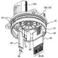
ECU 하우징(11B)의 단부면에는 커넥터 단자 조립체를 겸용하는 합성수지제의 덮개(12)가 고정 볼트에 의해서 고정된다. 덮개(12)에는 전력 공급용의 커넥터 단자 형성부(12A), 검출 센서용의 커넥터 단자 형성부(12B), 제어 상태를 외부 기기에 송출하는 제어 상태 송출용의 커넥터 단자 형성부(12C)를 구비한다. 그리고, ECU 하우징(11B)에 수납되는 전자 제어 조립체는, 합성수지로 만들어진 덮개(12)의 전력 공급용의 커넥터 단자 형성부(12A)를 통해 전원으로부터 전력이 공급되고, 또한 검출 센서류로부터 운전 상태 등의 검출 신호가 검출 센서용의 커넥터 형성 단자부(12B)를 통해 공급되며, 현재의 전동 파워 스티어링 장치의 제어 상태 신호가 제어 상태 송출용의 커넥터 단자 형성부(12C)를 통해 송출된다.A
여기서, 덮개(12)는 ECU 하우징(11B)의 개구부 전체를 덮는 형상으로 이루어지지만, 각 커넥터 단자를 소형으로 형성하여, ECU 하우징(11B)에 형성되는 삽입 구멍을 삽입 관통하여 전자 제어 조립체와 접속하는 구성으로 하여도 좋다.Here, the
이상과 같은 구성의 전동 파워 스티어링 장치(6)에 있어서는, 핸들이 조작됨으로써 스티어링 샤프트(2)가 어느 한 방향으로 회동 조작되면, 이 스티어링 샤프트(2)의 회동 방향과 회동 토크를 토크 센서(7)가 검출하고, 이 검출치에 기초하여 제어 회로부가 전동 모터의 구동 조작량을 연산한다. 이 연산한 구동 조작량에 기초하여 전력 변환 회로부의 파워 스위칭 소자에 의해 전동 모터가 구동되고, 전동 모터의 출력축은 스티어링 샤프트(1)를 조작 방향과 동일한 방향으로 구동하도록 회동된다. 출력축의 회동은, 도시하지 않은 피니언으로부터 기어(10)를 통해 도시하지 않은 랙에 전달되어, 자동차가 조타된다. 이들 구성, 작용은 이미 잘 알려져 있기 때문에 이 이상의 설명은 생략한다.In the electric
이러한 전동 파워 스티어링 장치에 있어서, 자동차의 엔진룸 내부는, 배기가스 대책 기기나 안전 대책 기기 등의 보조 기계류가 많이 설치되는 경향이 있어, 전동 파워 스티어링 장치를 포함하여 각종 보조 기계류는 가능한 한 소형화할 것이 요구되고 있다. 전동 파워 스티어링 장치에 있어서는, 전동 모터를 제어하기 위한 필요한 전원 회로부, 전력 변환 회로부 및 제어 회로부를 구성하는 전기 부품의 부품 점수는 대략 정해져 있다. 이 때문에, 특허문헌 1과 같이 2장의 기판에 이들 부품 점수의 전기 부품을 실장하면, 전자 제어 장치를 수납하는 하우징이 자연히 반경 방향으로 커진다.In such an electric power steering apparatus, many auxiliary machinery such as an exhaust gas countermeasure device and a safety countermeasure tends to be installed in the engine room of an automobile, and various auxiliary machinery including an electric power steering device should be made as small as possible . In the electric power steering apparatus, the number of parts of the electric parts constituting the power supply circuit portion, the power conversion circuit portion, and the control circuit portion necessary for controlling the electric motor is approximately determined. For this reason, when the electric parts of these parts are mounted on the two boards as in Patent Document 1, the housing for housing the electronic control device naturally becomes larger in the radial direction.
따라서, 직경 방향으로 소형화하기 위해서 전원 회로부, 전력 변환 회로부 및 제어 회로부를 개별로 3 분할하는 것이 유효하다. 이에 따르면, 전동 모터를 제어하기 위해 필요한 전기 부품을 3 분할하기 때문에, 2 분할하는 것보다도 기판의 면적을 작게 하여 반경 방향으로 소형화할 수 있게 된다.Therefore, it is effective to divide the power supply circuit portion, the power conversion circuit portion, and the control circuit portion into three in order to reduce the size in the radial direction. According to this, since the electric parts required for controlling the electric motor are divided into three parts, the area of the board can be made smaller than that of the electric parts divided into two parts, and the electric parts can be downsized in the radial direction.
그러나, 이 3 분할된 각 기판에 전력이나 제어 신호 등을 공급하기 위해서는, 많은 중계 커넥터를 사용하는 복잡한 커넥터 배선부의 구성이 필요하게 되어, 부품 점수가 증가한다는 과제나 소형화의 장해가 된다는 과제가 있다. 나아가서는 커넥터 배선부의 구성이 복잡하기 때문에, 조립 공수가 늘어남으로 인한 제품 단가의 상승과 같은 과제가 있다.However, in order to supply power, control signals, and the like to each of the three divided substrates, a complicated connector wiring portion using a large number of relay connectors is required, which poses a problem of increasing the number of parts and a problem of miniaturization . Furthermore, since the configuration of the connector wiring portion is complicated, there is a problem such as an increase in the product unit price due to an increase in the number of assembly operations.
이러한 배경에서, 본 실시예에서는 다음과 같은 구성의 전동 파워 스티어링 장치를 제안하는 것이다.In this background, the present embodiment proposes an electric power steering apparatus having the following configuration.
즉, 전자 제어 조립체를, 전원의 생성을 주된 기능으로 하는 금속 기판에 실장되는 전원 회로부와, 전동 모터의 구동을 주된 기능으로 하는 금속 기판에 실장되는 전력 변환 회로부와, 전력 변환 회로부의 제어를 주된 기능으로 하는 수지 기판에 실장되는 제어 회로부로 분할함과 함께, 적어도, 전원 회로부에서 전력 변환 회로부 및 제어 회로부로 전력을 공급하는 전력 공급 커넥터 배선부와, 제어 회로부의 입출력 신호를 전송하는 신호 전송 커넥터 배선부를 합성수지로 이루어지는 커넥터 단자 조립체에 매설함과 더불어, 커넥터 단자 조립체로부터 노출되는 전력 공급 커넥터 배선부 및 신호 전송 커넥터 배선부의 커넥터 단자를, 대응하는 전원 회로부, 전력 변환 회로부 및 제어 회로부의 커넥터에 직접적으로 접속하는 구성으로 한 것이다.That is, the electronic control assembly includes a power supply circuit portion mounted on a metal substrate having a main function of generating power, a power conversion circuit portion mounted on a metal substrate having a main function of driving the electric motor, A power supply connector wiring part for supplying power to the power conversion circuit part and the control circuit part in at least the power supply circuit part and a signal transmission connector for transmitting the input / output signal of the control circuit part to the control circuit part, The wiring portions are embedded in the connector terminal assembly made of synthetic resin and the connector terminals of the power supply connector wiring portion and the signal transmission connector wiring portion exposed from the connector terminal assembly are directly connected to the corresponding power supply circuit portion, As shown in Fig.
이하, 본 발명의 일 실시형태가 되는 전동 파워 스티어링 장치의 구성에 관해서 설명하는데, 이하의 도면에서는 도 2에 도시하는 덮개(12)의 형상이 상이하다. 그러나, 그 기능은 동일하다.Hereinafter, a configuration of an electric power steering apparatus according to an embodiment of the present invention will be described. In the following drawings, the shape of the
도 3에 전동 파워 스티어링 장치(6)의 분해 사시도를 도시하고 있다. 또, 모터 하우징(11A)에는 통상은 전동 모터가 수납된다. 그리고, 상술한 것과 같이 모터 하우징(11A)과 ECU 하우징(11B)은 별개 부재의 알루미늄 합금으로 만들어져 있지만, 양 하우징은 동일한 하우징으로 하여도 좋다.Fig. 3 shows an exploded perspective view of the electric
전자 제어 장치부(9)는, 모터 하우징(11A) 내의 전동 모터의 도시하지 않은 출력축과 반대쪽에 결합되는 ECU 하우징(11B)과, ECU 하우징(11B)에 3개의 고정 볼트(13)에 의해서 결합되는 덮개(12)로 구성된다. 덮개(12)는 후술하는 것과 같이, 커넥터 단자 조립체를 겸용하는 것이며, 합성수지로 사출성형에 의해서 형성된다. 또, 이 덮개(12)에는 후술하는 것과 같은 각종 커넥터 배선부가 동시에 인서트 몰드에 의해서 매설된다.The
ECU 하우징(11B) 및 덮개(12)로 구성되는 수용 공간에는, 전원 회로부(14), 전력 변환 회로부(15), 제어 회로부(16) 등으로 이루어지는 전자 제어 조립체가 수납된다. ECU 하우징(11B)의 내부에는 알루미늄 혹은 알루미늄 합금 등의 금속으로 만들어진 금속 기판(17, 18)이 배치되고, 이들 금속 기판(17, 18)에는 한쪽 면 실장에 의해서 전원 회로부(14) 및 전력 변환 회로부(15)를 구성하는 전기부품이 배치된다.An electronic control assembly including a power
이들 금속 기판(17, 18)은 후술하는 것과 같이 방열 부재로서 기능하는 것으로, ECU 하우징(11B)과 열적으로 접촉하여 방열할 수 있게 배치된다.These
즉, 금속 기판(17, 18)은 전원 회로부(14)와 전력 변환 회로부(15)로부터의 열을 ECU 하우징(11B)으로 방열하는 기능을 구비하고, 이 때문에, ECU 하우징(11B)의 내주 측과 금속 기판(17, 18)의 외주 측은 열적으로 접촉하는 구성으로 이루어진다.That is, the
또, 이 밖에 금속 기판(17, 18)을 덮개(12)에 고정하는 고정 볼트(도 9에 도시하는 고정 볼트(44))를 통해 덮개(12)로 방열시킬 수도 있다. 이 경우는, 덮개(12)의 내부에 인서트 너트를 매설하고, 이 인서트 너트를 ECU 하우징(11B)과 열적으로 접속하면 된다.It is also possible to dissipate heat to the
여기서, 금속 기판(17, 18)은 방열 기능을 높이기 위해서 두께를 두껍게 형성하고 있다. 또한, 이 열적인 접촉을 높이기 위해서 열전도성이 좋은 방열 접착제, 방열 시트, 방열 그리스 등의 방열 기능재가 금속 기판(17, 18)의 외주면과 ECU 하우징(11B)의 내주면의 사이에 개재된다. 또, 이 금속 기판(17, 18)의 두께를 두껍게 한 이유는, 도 9의 설명에서 상세하게 설명하기로 한다.Here, the
덮개(12)의 내측에는, 전동 모터를 구동하는 인버터 장치에 사용되는 고압 직류 전원과, 마이크로컴퓨터 등의 제어 회로에 사용되는 저압 직류 전원의 생성을 주된 기능으로 하는 전원 회로부(14)가 배치된다. 이 전원 회로부(14)는 도 4에 도시한 것과 같이, 알루미늄 등의 열전도성이 좋은 금속으로 이루어지는 금속 기판(17)의 한쪽 면 위에, 콘덴서(19), 코일(20), MOSFET로 이루어지는 스위칭 소자(21), 배터리로부터의 전원 측의 커넥터 단자가 접속되는 전원 측의 커넥터(22), 전력 변환 회로부(15)에 고압 전원을 공급하는 고압 측의 커넥터 단자가 접속되는 고압 측의 커넥터(23), 제어 회로부(16)에 저압 전원을 공급하는 저압 측의 커넥터 단자가 접속되는 저압 측의 커넥터(24) 등의 전기 부품이 실장된다. 금속 기판(17)은, 알루미늄 기판 위에 절연층을 형성하고, 이 절연층 위에 동박으로 이루어지는 배선 패턴을 인쇄하여 구성되고, 이 위에 전기 부품이 배치되어 각각의 전기 부품이 전기적으로 접속된다.On the inside of the
전원 회로부(14)에는, 콘덴서(19)나 코일(20), 커넥터(22~24) 등의 비교적 형상이 큰(=키가 큰) 전기 부품이 사용된다. 또, 커넥터(22, 23)는 프레스피트형의 커넥터이며, 내측을 향해서 탄발성을 구비하고, 이 커넥터(22, 23)에 커넥터 단자를 삽입하는 것만으로 간단하게 상호 접속을 확보할 수 있다.Electric parts having a relatively large shape (= large) such as a
그리고, ECU 하우징(11B)에는, 전동 모터의 구동을 주된 기능으로 하는 인버터 제어를 실행하는 전력 변환 회로부(15)가 배치된다. 이 전력 변환 회로부(15)는, 전원 회로부(14)의 금속 기판(17)에 대향하도록 전력 변환 회로부(15)의 금속 기판(18)을 배치한다. 즉, 도면으로부터 알 수 있는 것과 같이, 전원 회로부(14)의 금속 기판(17)에 대향하여 접촉하는 형태로 전력 변환 회로부(15)의 금속 기판(18)이 배치된다.The
이 전력 변환 회로부(15)의 금속 기판(18)과 전원 회로부(14)의 금속 기판(17)의 대향면(=접촉면)은, 실질적으로 동일한 형상을 구비하, 열이 서로 전해지기 쉽게 이루어진다. 더욱이, 양자 사이에는 열전도성이 좋은 방열 접착제, 방열 시트, 방열 그리스 등의 방열 기능재가 개재된다.The
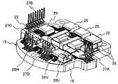
전력 변환 회로부(15)는 도 5에 도시한 것과 같이, 알루미늄 등의 열전도성이 좋은 금속으로 이루어지는 금속 기판(18) 상에, 복수의 MOSFET 혹은 IGBT으로 이루어지는 파워 스위칭 소자(25) 및 이것의 출력용 출력 커넥터(26U, 26V, 26W), 그리고 스위칭 소자(25)를 제어하는 게이트, 드레인, 소스 등의 입력 신호의 입력이나 스위칭 소자(25)의 동작 상황을 제어 회로부(16)에 피드백하기 위한 커넥터 단자(27A~27D) 등이 실장된다. 또한, 전원 회로부(14)로부터 전력의 공급을 받는 인버터 측의 커넥터(28)도 설치된다. 또한, 스위칭 소자(25)는, 전동 모터를 제어하는 6개의 스위칭 소자(25) 이외에 페일 세이프(fail safe)용의 3개의 스위칭 소자(25)도 구비한다.As shown in Fig. 5, the power
또한, 출력용의 커넥터(26U, 26V, 26W)는 프레스피트형의 커넥터이며, 내측을 향해서 탄발성을 구비하고, 이 커넥터(26U, 26V, 26W)에 전동 모터에 접속된 버스 바의 커넥터 단자를 삽입하는 것만으로 간단하게 상호 접속을 확보할 수 있다.The
금속 기판(18)은, 알루미늄 기판 위에 절연층을 형성하고, 이 절연층 위에 동박으로 이루어지는 배선 패턴을 인쇄하여 구성되며, 이 위에 전기 부품이 배치되어 각각의 전기 부품이 전기적으로 접속된다. 또한, 도 5는 이해하기 쉽게 상술한 전기 부품을 배치한 쪽을 도시하고 있지만, 실제로는 도 3에 있는 것과 같이, 전기 부품이 아래쪽으로 되도록 배치된다.The
전력 변환 회로부(15)와 모터 하우징(11A)의 사이에는, 전력 변환 회로부(15)의 스위칭 소자(25)의 스위칭 제어 등을 주된 기능으로 하는 제어 회로부(16)가 배치된다. ECU 하우징(11B)에는, 모터 하우징(11A) 측을 향해서 4개의 수지 기판 부착 보스(29)가 형성되고, 이 수지 기판 부착 보스(29)에 제어 회로부(16)의 수지 기판이 부착 볼트(30)로 고정된다.Between the power
제어 회로부(16)는 도 6에 도시한 것과 같이, 합성수지 등으로 이루어지는 수지 기판(31) 상에, 스위칭 소자(25) 등을 제어하는 마이크로컴퓨터(32) 등이 실장된다. 또한, 수지 기판(31) 상에는 마이크로컴퓨터(32)의 주변 회로 등의 전기 부품이 배치되지만, 도 6에서는 생략하고 있다.6, a
수지 기판(31)은 전력 변환 회로부(15)와는 소정의 거리를 두고서 배치되고, 그 사이의 공간에 전력 변환 회로부(15)의 전기 부품이 배치된다. 그리고, 제어 회로부(16)와 전력 변환 회로부(15)는 상술한 커넥터 단자(27A~27D)에 의해서 접속된다.The
커넥터 단자(27A~27D)는, 수지 기판(31)과 전력 변환 회로부(15) 사이의 소정 거리를 넘는 길이를 갖는다. 그리고, 커넥터 단자(27A)는 수지 기판(31)의 접속 구멍(33A)에 접속되고, 커넥터 단자(27B)는 접속 구멍(33B)에 접속되며, 커넥터 단자(27C)는 접속 구멍(33C)에 접속되고, 커넥터 단자(27D)는 접속 구멍(33D)에 접속되도록 이루어진다.The
또, 제어 기판(31)에 형성한 접속 구멍(33E)에는, 후술하는 덮개(12)의 절연 영역부에 매설한 신호 전송용 및 저압 전원 공급용의 제어 측의 커넥터 단자가 접속된다.Connected to the
이와 같이, 덮개(12)에서 모터 하우징(11A) 측을 향하여, 전원 회로부(14), 전력 변환 회로부(15) 및 제어 회로부(16)의 순서로 배치된다. 이와 같이 전원 회로부(14)로부터 거리를 두고서 제어 회로부(16)를 배치함으로써, 전원 노이즈를 제거한 후에 제어 회로부(16)에 안정된 전원을 제공할 수 있게 된다.The power
도 3으로 되돌아가면, 커넥터 배선부가 매설된 덮개(12)는, ECU 하우징(11B)의 개구를 덮는 것으로, 도 2에 도시하는 것과 같이, 축 방향의 외표면에 전력 공급용의 커넥터 단자 형성부(12A), 검출 센서용의 커넥터 단자 형성부(12B), 제어 상태를 외부 기기에 송출하는 제어 상태 송출용의 커넥터 단자 형성부(12C)를 구비한다. 또한, 커넥터 단자 형성부(12B)와 커넥터 단자 형성부(12C)를 일체로 형성하더라도 지장 없는 것이다.3, the
그리고, 이들 커넥터 단자 형성부(12A~12C)를 통해, 도시하지 않은 전원으로부터 전원 회로부(14)에 전력이 공급된다. 마찬가지로 검출 센서의 신호 등이 제어 회로부(16)에 입력된다.Power is supplied to the power
덮개(12)의 구체적인 구성을 도 7에 도시하고 있다. 이 도 7에 있어서, 커넥터 단자 조립체를 겸하는 덮개(12)는 내부에 각종 커넥터 배선부와 그 커넥터 단자를 구비한다.A specific configuration of the
우선 첫째로, 외부 전원(=차량 탑재 배터리)과 접속되는 커넥터 단자 형성부(12A)와 전원 회로부(14)를 접속하는 전력 공급용의 커넥터 배선부인 전원 커넥터 배선부가 덮개(12)에 매설되고, 선단의 전원 측의 커넥터 단자(34)가 덮개(12)로부터 노출된다. 이 전원 측의 커넥터 단자(34)는 덮개(12)의 옆둘레면(후술하는 ECU 하우징과 시일 영역을 형성하는 면)의 내측에 위치한다. 전원 측의 커넥터 단자(34)는, 전원 회로부(14)의 전원 측의 커넥터(22)에 접속되는 것으로, 전원 측의 커넥터 단자(34)를 프레스피트형의 전원 측의 커넥터(22)에 삽입하는 것만으로 간단하게 접속이 완료된다. 또, 전원 커넥터 배선부에 관해서는 도 11에 도시되어 있다.First, the power source connector wiring portion which is a connector wiring portion for power supply for connecting the connector
이어서, 전원 회로부(14)와 전력 변환 회로부(15)를 접속하는 전력 공급용의 커넥터 배선부인 고압 측의 커넥터 배선부가 덮개(12)에 매설된다. 이 고압 측의 커넥터 배선부의 양끝은, 고압 측의 커넥터 단자(35)와 인버터 측의 커넥터 단자(36)로서 형성되어 덮개(12)로부터 노출된다. 한쪽의 고압 측의 커넥터 단자(35)는 전원 회로부(14)의 고압 측의 커넥터(23)에 접속되고, 다른 쪽의 인버터 측의 커넥터 단자(36)는 전력 변환 회로부(15)의 인버터 측의 커넥터(28)에 접속된다. 마찬가지로, 고압 측의 커넥터 배선부에 관해서는 도 10에 도시되어 있다.Next, a connector wiring portion on the high voltage side, which is a connector wiring portion for power supply, which connects the power
고압 측의 커넥터 단자(35)는, 전원 회로부(14)의 고압 측의 커넥터(23)에 접속되는 것으로, 고압 측의 커넥터 단자(35)를 프레스피트형의 고압 측의 커넥터(23)에 삽입하는 것만으로, 간단하게 접속이 완료된다. 또한, 인버터 측의 커넥터 단자(36)는, 전력 변환 회로부(15)의 인버터 측의 커넥터(28)에 접속되는 것으로, 인버터 측의 커넥터 단자(36)와 인버터 측의 커넥터(28)를 TIG 용접함으로써 접속이 완료된다.The
이 고압 측의 커넥터 배선부는, 고압 측의 커넥터 단자(35)와 인버터 측의 커넥터 단자(36)의 사이에서, 그 단면 형상이 인버터 측의 커넥터 단자(36) 쪽이 긴 「ㄷ」자형으로 이루어진다. 이 긴 부분은 덮개(12)를 형성하는 합성수지에 매설되어 고압 측의 절연 영역부(45)로 이루어지고, 이 고압 측의 절연 영역부(45)는, 도 10에 있는 것과 같이 금속 기판(17, 18)의 외주 측의 단부면에 형성한 삽입 관통부를 삽입 관통하여, 전력 변환 회로부(15)까지 연장된다. 여기서, 이 삽입 관통부는 금속 기판(17, 18)의 외주 측에 형성한 「절결」이라도 좋고, 혹은 「삽입 관통 구멍」이라도 좋은 것이다. 또한, 고압 측의 커넥터 배선부를 구성하는 고압 측의 절연 영역부(45)는 금속 기판(17, 18)의 외주 측과 커넥터 덮개(12)의 옆둘레면의 내측의 사이에 위치한다. 이에 관해서는 도 10에서 상세히 설명한다.This connector wiring portion on the high voltage side has a cross-sectional shape between the
이어서, 전원 회로부(14)와 제어 회로부(16)를 접속하는 전력 공급용의 커넥터 배선부인 저압 측의 커넥터 배선부가 덮개(12)에 매설된다. 이 저압 측의 커넥터 배선부의 양끝은, 저압 측의 커넥터 단자(37)와 제어 측의 커넥터 단자(38)로서 형성되어 덮개(12)로부터 노출된다. 한쪽의 저압 측의 커넥터 단자(37)는 전원 회로부(14)의 저압 측의 커넥터(24)에 접속되고, 다른 쪽의 제어 측의 커넥터 단자(38)는 제어 회로부(16)의 접속 구멍(33E)에 접속된다.Next, a connector wiring portion on the low-voltage side which is a connector wiring portion for power supply connecting the power
또한, 저압 측의 커넥터 배선부에 인접하여, 검출 센서용의 커넥터 단자 형성부(12B), 제어 상태 송출용의 커넥터 단자 형성부(12C)와 접속되는, 신호 전송용의 신호 전송 커넥터 배선부가 덮개(12)에 매설되고, 제어 측의 커넥터 단자(39)가 덮개(12)로부터 노출된다.The signal transmission connector wiring section for signal transmission, which is connected to the connector
마찬가지로, 저압 측의 커넥터 배선부에 관해서는 도 11에 도시되어 있다.Likewise, the connector wiring portion on the low-voltage side is shown in Fig.
저압 측의 커넥터 단자(37)는, 전원 회로부(14)의 저압 측의 커넥터(24)에 접속되는 것으로, 저압 측의 커넥터 단자(37)를 소켓형의 저압 측의 커넥터(24)에 끼워 맞추는 것만으로 접속이 완료된다. 또한, 제어 측의 커넥터 단자(38) 및 신호 전송용의 제어 측의 커넥터 단자(39)는, 제어 회로부(16)의 접속 구멍(33E)에 접속되는 것으로, 제어 측의 커넥터 단자(38, 39)와 접속 구멍(33E)을 땜납에 의해서 접합함으로써 접속이 완료된다.The
상술한 저압 측의 커넥터 배선부와 신호 전송 커넥터 배선부는, 덮개(12)를 형성하는 합성수지에 매설되어 저압 측의 절연 영역부(46)로 이루어지고, 이 저압 측의 절연 영역부(46)는, 도 11에 있는 것과 같이 금속 기판(17, 18)의 외주 측의 단부면에 형성한 삽입 관통부를 삽입 관통하여, 제어 회로부(16)까지 연장된다. 여기서, 이 삽입 관통부는 금속 기판(17, 18)의 외주에 형성한 「절결부」라도 좋고, 혹은 「삽입 관통 구멍」이라도 좋은 것이다. 또한, 저압 측의 커넥터 배선부를 구성하는 저압 측의 절연 영역부(46)는 금속 기판(17, 18)의 외주 측과 커넥터 덮개(12)의 옆둘레면의 내측의 사이에 위치한다. 이것에 관해서는 도 11에서 상세히 설명한다.The low-voltage side connector wiring portion and the signal transfer connector wiring portion are made of a low-pressure
도 7로부터 알 수 있는 것과 같이, 덮개(12)의 내주면에는 전원 회로부(14)와 전력 변환 회로부(15)의 금속 기판(17, 18)을 고정하기 위한 금속 기판 부착 보스(43)가 형성된다. 또한 덮개(12)의 내주면에 근접하여, 전원 측의 커넥터 단자(34), 고압 측의 커넥터 단자(35), 인버터 측의 커넥터 단자(36), 저압 측의 커넥터 단자(37), 제어 측의 커넥터 단자(38) 및 신호 전송용의 제어 측의 커넥터 단자(39)가 배치된다.7, a metal
즉, 전원 회로부(14), 전력 변환 회로부(15) 및 제어 회로부(16)의 각 기판의 외주 측에 치우쳐, 전원 측의 커넥터 단자(34), 고압 측의 커넥터 단자(35), 인버터 측의 커넥터 단자(36), 저압 측의 커넥터 단자(37), 제어 측의 커넥터 단자(38) 및 신호 전송용의 제어 측의 커넥터 단자(39)가 위치하도록 배치된다.The
이에 따라, 전원 회로부(14), 전력 변환 회로부(15) 및 제어 회로부(16)를 구성하는 전기 부품을 각 기판의 중앙에 바싹 붙여 배치할 수 있기 때문에, 반경 방향을 향해서 소형화가 가능하게 된다.As a result, the electric parts constituting the power
또한, 만일 상술한 각 단자부 중의 몇 개를 각 기판의 내주 측으로 통과시키면, 금속 기판(17, 18)에, 이를 위한 삽입 관통부를 형성해야 하지만, 이와 같이 하면, 금속 기판(17, 18)의 방열 통로 단면적이 좁아져 방열이 나빠질 우려가 있다.In addition, if some of the above-mentioned terminal portions are passed to the inner circumferential side of each substrate, the insertion holes for the
이에 대하여, 본 실시예에서는 각 커넥터 단자를 포함한 커넥터 배선부를 금속 기판(17, 18)의 외측에 위치하도록 배치하고 있기 때문에, 금속 기판(17, 18)의 내주 측에 필요 없는 삽입 관통부를 형성하지 않아도 되어, 방열 통로 단면적을 충분히 확보할 수 있다고 하는 효과를 발휘할 수 있다.On the contrary, in the present embodiment, since the connector wiring portions including the respective connector terminals are disposed on the outside of the
본 실시예에서의 덮개(12)에 있어서는, 전원 회로부(14)에서 전력 변환 회로부(15) 및 제어 회로부(16)로 전력을 공급하는 커넥터 배선부와, 제어 회로부의 입출력 신호를 전송하는 커넥터 배선부를, 합성수지로 이루어지는 커넥터 단자 조립체에 인서트 성형에 의해서 매설함과 더불어, 커넥터 단자 조립체로부터 노출되는 전력을 공급하는 커넥터 배선부 및 신호 전송을 하는 커넥터 배선부의 각각의 커넥터 단자를, 대응하는 전원 회로부, 전력 변환 회로부 및 제어 회로부에 직접적으로 접속하는 구성으로 이루어진다.The
이 때문에, 전력 변환 회로부(15)와 제어 회로부(16) 사이의 배선을 제외하고, 각 커넥터 배선부는 여분의 중계 커넥터 부품 등을 이용하지 않고서 직접적으로 각각이 대응하는 커넥터에 접속된다. 따라서, 여분의 중계 부품 등이 필요 없기 때문에, 부품 점수를 저감하여 소형화를 도모할 수 있게 된다. 나아가서는, 커넥터 배선부의 구성이 간단하기 때문에 조립 공수가 늘어나는 것을 억제하여 제품 단가의 상승을 억제할 수 있게 된다.Therefore, except for the wiring between the power
또한, 본 실시예에서는 각 커넥터 단자를 포함한 커넥터 배선부를 금속 기판(17, 18) 및 수지 기판(31)의 외측에 위치하도록 배치하고 있기 때문에, 금속 기판(17, 18)의 내주 측에 필요 없는 삽입 관통부를 형성하지 않으므로, 방열 통로 단면적을 충분히 확보할 수 있다고 하는 효과를 발휘할 수 있게 된다.In the present embodiment, since the connector wiring portions including the connector terminals are disposed on the outer sides of the
또, 도 3에 도시하는 전동 파워 스티어링 장치를 조립하는 순서는 다음과 같다. 우선, 전원 회로부(14)와 전력 변환 회로부(15)의 금속 기판(17, 18)을 대향시켜 고정 볼트(44)를 삽입 관통시키고, 고정 볼트(44)를 덮개(12)에 형성한 금속 기판 부착 보스(43)에 비틀어 넣어, 전원 회로부(14)와 전력 변환 회로부(15)와 덮개(12)를 일체화한다.The procedure for assembling the electric power steering apparatus shown in Fig. 3 is as follows. First, the fixing
이 상태에서, 전원 회로부(14)의 전원 측의 커넥터(22)와 전원 측의 커넥터 단자(34)의 접속이 완료되고, 또한, 고압 측의 커넥터 배선부의 고압 측의 커넥터(23)와 고압 측의 커넥터 단자(35)의 접속이 완료되며, 또한, 저압 측의 커넥터(24)와 저압 측의 커넥터 단자(37)의 접속이 완료된다.In this state, the connection between the
이어서, 이 상태에서 제1 절연 영역부(45)가 전력 변환 회로부(15)로부터 돌출되기 때문에, 여기로부터 노출되는 인버터 측의 커넥터 단자(36)와 인버터 측의 커넥터(28)를 TIG 용접용 토치를 사용하여 접합한다.Since the
이어서, ECU 하우징(11B)을 덮개(12)를 향해서 삽입하여 고정 볼트(13)로 양자를 고정한다. 이 후에 제어 회로부(16)를 고정 볼트(30)에 의해서 수지 기판 부착 보스(29)에 고정하여, 제어 회로부(16)와 ECU 하우징(11B)을 일체화한다.Then, the
이 상태에서, 제어 회로부(16)의 수지 기판(31)에 형성한 각 접속 구멍(33A~33E)과, 이것에 대응한 각 커넥터 단자(27A~27D, 38, 39)를 납땜하여 접합한다. 이와 같이 하여 전자 제어 장치(9)가 완성된다.In this state, the connection holes 33A to 33E formed in the
그리고, ECU 하우징(11B)에 형성된 부착 플랜지를 이용하여, 전자 제어 장치(9)를 모터 하우징(11A)에 고정 볼트에 의해서 고정함으로써, 모터 하우징(11A)과 ECU 하우징(11B)이 일체화된다.The
이어서 도 8 내지 도 11을 이용하여 ECU 하우징(11B)에 수납되는 전자 제어 조립체의 구성에 관해서 상세히 설명한다.Next, the configuration of the electronic control assembly housed in the
도 8은 도 3에 도시하는 A-A면에서 덮개(12)의 방향을 본 도면이며, 전력 변환 회로부(15)의 평면이 도시되어 있다. 전력 변환 회로부(15)의 상세한 구성은 도 5에 도시한 것과 같기 때문에 설명은 생략하지만, 중요한 점은, 금속 기판(18)의 외주 측의 단부면에 형성한 삽입 관통부(40A, 47)가 형성되는 것이다.Fig. 8 is a view showing the direction of the
삽입 관통부(40A)는 금속 기판(18)의 외주에 형성한 직선형의 절결부이며, 이 삽입 관통부(40A)를 지나 상술한 저압 측의 절연 영역부(46)가 제어 회로부(16) 측까지 연장되어 있다. 이와 같이 직선형의 「절결부」로 한 것은, 저압 측의 절연 영역부(46)를 지나는 배선부의 라인수가 많아, 「절결부」의 면적을 크게 하여 저압 측의 절연 영역부(46)를 삽입 관통시키기 위해서이다. 물론, 금속 기판(17)에도, 도 11에 도시한 것과 같이 금속 기판(18)에 형성한 삽입 관통부(40A)와 일치하는 삽입 관통부(40B)가 형성되는 것은 말할 것도 없다.The
마찬가지로, 삽입 관통부(47)는 금속 기판(18)의 외주에 형성한 「절결부」이며, 이 삽입 관통부(47)를 지나 상술한 고압 측의 절연 영역부(45)가 전력 변환 회로부(15) 측으로 연장된다. 물론 금속 기판(17)에도 금속 기판(18)에 형성한 삽입 관통부(47)와 일치하는 삽입 관통부가 형성되는 것은 말할 것도 없다.Similarly, the
이어서 도 8의 B-B면에서 본 전동 파워 스티어링 장치의 단면을 도 9에 기초하여 설명하지만, 이 도 9에서는 전동 모터 부분을 생략하고 있다.Next, a cross-sectional view of the electric power steering apparatus seen from the plane B-B of Fig. 8 will be described with reference to Fig. 9. In Fig. 9, the electric motor portion is omitted.
도 9에 있어서, ECU 하우징(11B)과 모터 하우징(11A)은, 각각에 형성한 부착 플랜지에 비틀려져 들어간 복수의 고정 볼트(41)에 의해서 고정된다. 마찬가지로 ECU 하우징(11B)과 덮개(12)는, 각각에 형성한 부착 플랜지에 비틀려져 들어간 복수의 고정 볼트(13)에 의해서 고정된다.In Fig. 9, the
ECU 하우징(11B)의 개구부 내에는, 덮개(12)의 커넥터 단자 형성부(12A~12C)를 제외한 부분이 수납되고, 덮개(12)의 외주면은 ECU 하우징(11B)의 내주면과 밀착되어 있다. 그리고, 그 덮개(12)의 외주면에는 시일 링(42)이 마련된다. 이 시일 링(42)에 의해서, 덮개(12)와 ECU 하우징(11B)의 사이에서 물 등이 침입하는 것을 방지한다.A portion of the
덮개(12)의 내주에는 전원 회로부(14)와 전력 변환 회로부(15)의 금속 기판(17, 18)을 고정하기 위한 금속 기판 부착 보스(43)가 형성된다. 이 금속 기판 부착 보스(43)는 일반적으로는 4 곳 형성하지만, 본 실시예에서는 도 3에 있는 것과 같이, 1 곳은 생략하고 3 곳에 형성되어 있다. 이 이유는, 가능한 한 전력 변환 회로부(15)의 금속 기판(18)의 면적을 작게 하기 위해서와, 고정 볼트의 개수를 저감하기 위해서이다.A metal
전원 회로부(14)의 금속 기판(17)과 전력 변환 회로부(15)의 금속 기판(18)에는, 고정 볼트(44)가 삽입 관통하는 삽입 관통 구멍이 형성되고, 고정 볼트(44)를 전력 변환 회로부(15)의 금속 기판(18) 측에서 금속 기판 부착 보스(43)에 비틀어 넣음으로써, 전원 회로부(14)의 금속 기판(17)과 전력 변환 회로부(15)의 금속 기판(18)을 금속 기판 부착 보스(43)에 강고히 고정하는 구성으로 이루어진다. 더욱이, 금속 기판(17)과 금속 기판(18)은 상호 마주 향해 배치되어, 서로 열의 이동이 가능하게 된다.Through holes through which the fixing
도 3에서 설명한 것과 같이, 금속 기판(17, 18)은 전원 회로부(14)와 전력 변환 회로부(15)로부터의 열을 ECU 하우징(11B)으로 방열하는 기능을 구비하고, 이 때문에, ECU 하우징(11B)의 내주 측과 금속 기판(17, 18)의 외주 측은 열적으로 접촉한다. 그리고, 이 열적인 접촉을 높이기 위해서 열전도성이 좋은 방열 접착제, 방열 시트, 방열 그리스 등의 방열 기능재가 금속 기판(17, 18)의 외주면과 ECU 하우징(11B)의 내주면의 사이에 개재된다.3, the
여기서, 본 실시예에서는 금속 기판(17, 18)은 방열 기능을 높이기 위해서, 그 두께를 두껍게 형성하고 있다. 통상은 금속 기판(17, 18)은 알루미늄 합금의 얇은 금속 기판을 사용하지만, 얇은 금속 기판을 사용하면 방열 통로의 단면적이 충분하지 않기 때문에, 얇은 금속 기판 내에서 열이 고이는 현상을 일으킨다. 이 때문에, 전원 회로부(14) 및 전력 변환 회로부(15)의 전기 부품에 열에 의한 악영향을 미치게 할 우려가 커진다.Here, in this embodiment, the
또한, 얇은 금속 기판의 방열성을 높이기 위해서, 별도 준비한 방열 기체(基體)에 얇은 금속 기판을 고정하는 방식도 있지만, 이 방법이면 방열 기체를 다이캐스트에 의해서 형(型) 성형으로 만들기 때문에 제조 비용이 높고, 금속 기판을 방열 기체에 고정하는 고정 볼트의 개수가 증가하여 부품 점수가 증가한다는 과제가 있다.(단, 본 발명은 이러한 방열 기체를 사용한 것이라도 적용할 수 있다.)In addition, in order to enhance the heat radiation of the thin metal substrate, there is a method of fixing a thin metal substrate to a heat radiating base prepared separately. However, in this method, since the heat radiating substrate is made into die by die casting, There is a problem that the number of fixing bolts for fixing the metal substrate to the heat dissipating body increases and the number of parts increases. (However, the present invention can be applied even to a case using such a heat radiating gas.)
이에 대하여, 본 실시예에서는, 금속 기판(17) 및 금속 기판(18)의 두께를 두껍게 하고, 또한 양자 사이를 방열 기능재에 의해서 열적으로 접속하여, 금속 기판(17)과 금속 기판(18)을 마치 두께가 두꺼운 방열 기체로서 취급하고 있다. 따라서, 금속 기판(17)과 금속 기판(18)에 의해서 방열 통로가 충분히 확보되어 전원 회로부(14) 및 전력 변환 회로부(15)의 전기 부품으로부터의 열을 밀어내는 것이 가능하게 된다.On the other hand, in the present embodiment, the thickness of the
본 실시예에서는, 종래의 얇은 금속 기판에 대하여 2배 이상의 두께를 갖도록 하고 있다.In this embodiment, the thickness of the conventional thin metal substrate is twice or more.
일반적으로는 종래의 얇은 금속 기판은 두께가 2 mm 정도이지만, 본 실시예에서는 4 mm~10 mm의 길이로 설정하고 있다. 또한, 금속 기판(17, 18)의 열은 ECU 하우징(11B)에 전해져, ECU 하우징(11B)의 외주면에서 대기로 방열된다.In general, a conventional thin metal substrate has a thickness of about 2 mm, but is set to a length of 4 mm to 10 mm in the present embodiment. The heat of the
여기서, 고정 볼트(44)에 의해서 전원 회로부(14)의 금속 기판(17)과 전력 변환 회로부(15)의 금속 기판(18)을 결합함으로써, 마치 일체적인 방열 기체로서 전원 회로부(14)와 전력 변환 회로부(15)의 방열 통로를 확대할 수 있고, 나아가서는 고정 볼트의 개수를 저감하여 제품 단가를 내릴 수 있게 된다.The
앞서 말한 것처럼, 방열 기체를 사용하면, 다이캐스트에 의해서 형성되는 방열 기체가 필요하고, 각각의 금속 기판과 방열 기체를 결합하기 위한 고정 볼트의 개수가 늘어나고, 방열 그리스와 같은 방열 기능재가 방열 기체의 양면에 필요하므로 부품 점수가 증가한다.As described above, when a heat radiating base is used, a heat radiating body formed by die casting is required, the number of fixing bolts for coupling the respective metal substrates to the heat radiating body is increased, and a heat radiating functional material such as heat- The number of parts required increases on both sides.
그러나, 본 실시예에 따르면, 금속 기판(17, 18)을 두껍게 하면 되기 때문에, 일부러 다이캐스트에 의한 형 성형에 의해서 방열 기체를 제작할 필요가 없어져, 제조 단가를 낮게 억제할 수 있게 된다. 또한, 방열 기체에 각각의 금속 기판(17, 18)을 고정하기 위한 고정 볼트의 개수나 방열 기능 부재의 설치 부위를 저감할 수 있고, 결과적으로 부품 점수나 조립 공수를 저감할 수 있어, 종합적인 제품 단가의 상승을 억제할 수 있게 된다.However, according to the present embodiment, since the
또한, 전원 회로(14)의 금속 기판(17)과 덮개(12)의 내측 저면부의 사이에는, 전원 회로를 구성하는 콘덴서나 코일 등의 형상이 큰 전기 부품을 수납한다. 이들 전기 부품은 형상이 크기 때문에 큰 수납 공간이 필요하다. 그래서 본 실시예에서는, 덮개(12)의 외주면과 ECU 하우징(11B)의 내주면 사이에 형성되는 시일 영역이 긴 것을 이용하여 큰 수납 공간을 형성하고 있다.Between the
즉, 전동 파워 스티어링 장치는 자동차의 엔진룸 내에 배치되므로, 빗길 주행이나 웅덩이가 있는 도로를 주행하는 경우, 빗물이나 웅덩이의 물에 의해서, 전동 파워 스티어링 장치에 물이 묻는 경우가 종종 발생한다. 이 때문에, ECU 하우징(11B)과 덮개(12)의 접촉 영역은 수밀성을 충분히 확보할 필요가 있어, 양자의 시일 영역을 길게 하여, 그 시일 영역에 2개의 시일 링(42)을 배치하고 있다.That is, since the electric power steering device is disposed in the engine room of an automobile, when the vehicle travels on a road with a comb or running on a puddle, water sometimes gets into the electric power steering device due to rainwater or water in the puddle. Therefore, the contact area between the
이와 같이, 이중으로 시일 링(42)을 설치하기 때문에, 확실한 수밀성을 확보할 수 있음과 더불어, 긴 시일 영역에 의해서, 덮개(12)와 전원 회로부(14)의 금속 기판(17)의 사이에 큰 수용 공간이 형성되어, 큰 전기 부품으로 이루어지는 전원 회로부(14)를 용이하게 수용할 수 있게 된다. 이와 같이, 수밀성을 확보하기 위해서 생기는 공간을 유효하게 이용하여, 큰 전기 부품으로 이루어지는 전원 회로부(14)를 수납하도록 하고 있다.Since the sealing
이에 따라, 축 길이를 가능한 한 짧게 하는 것이 가능하게 된다. 또한, 전원에 접속된 전원 측의 커넥터 단자(34)가, 전원 회로부(14)의 프레스피트형의 전원 측의 커넥터(22)와 대향하여 직접적으로 삽입 접속되는 구성을 취하고 있기 때문에, 조립 작업이 용이하게 된다.As a result, the shaft length can be made as short as possible. Since the
이어서 도 8의 C-C면에서 본 전동 파워 스티어링 장치의 단면을 도 10에 기초하여 설명하지만, 이 도 10에서도 전동 모터 부분을 생략하고 있다.Next, a section of the electric power steering apparatus viewed from the plane C-C of Fig. 8 will be described based on Fig. 10, but the electric motor portion is omitted in Fig.
도 10에 있어서, 덮개(12)의 내측 저면부에서 제어 회로부(16) 측을 향하여 합성수지로 이루어지는 고압 측의 절연 영역부(45)가 연장된다. 이 고압 측의 절연 영역부(45)는 금속 기판(17)의 외주부에 형성한 삽입 관통부(47) 및 금속 기판(18)의 외주부에 형성한 삽입 관통부(48)를 삽입 관통하여 전력 변환 회로부(15)까지 연장된다. 또한, 금속 기판(17, 18)의 삽입 관통부(47, 48)는 금속 기판(17, 18)의 외주면과 덮개의 옆둘레면의 사이에 형성된다.10, the insulating
고압 측의 절연 영역부(45)의 내부에는 고압 측의 커넥터 배선부(49)가 매설되고, 이 고압 측의 커넥터 배선부(49)의 한쪽에는 고압 측의 커넥터 단자(35)가 형성되고, 다른 쪽에는 인버터 측의 커넥터 단자(36)가 형성된다. 이와 같이 고압 측의 절연 영역부(45)에 의해서, 고압 측의 커넥터 배선부(49)와 각각의 금속 기판(17, 18)의 절연을 확보하고 있다.The high-voltage side
고압 측의 커넥터 단자(35)와 인버터 측의 커넥터 단자(36)를 포함한 고압 측의 커넥터 배선부(49)는 「ㄷ」자형으로 형성되고, 전원 회로부(14)의 고압 측의 커넥터(23)와 전력 변환 회로부(15)의 인버터 측의 커넥터(28)가 역방향으로 설치되기 때문에, 이들을 서로 접속할 수 있도록 한다.The high-voltage side
따라서, 덮개(12)를 ECU 하우징(11B)에 고정하는 경우는, 고압 측의 커넥터 단자(35)를 프레스피트형의 고압 측의 커넥터(23)에 꽂아 넣음으로써 접속하고, 인버터 측의 커넥터 단자(36)를 인버터 측의 커넥터(28)에 TIG 용접함으로써 접속할 수 있다. 또한, 이 때에는 제어 회로부(16)는 설치되어 있지 않고, TIG 용접용 토치를 인버터 측의 커넥터 단자(36)와 인버터 측의 커넥터(28)까지 가깝게 하기가 용이하게 되도록 이루어진다.Therefore, when the
본 실시예에서는 고압 측의 커넥터 배선부를 구성하는 고압 측의 절연 영역부(45)를 금속 기판(17, 18) 및 수지 기판(31)의 외측에 위치하도록 배치하고 있기 때문에, 금속 기판(17, 18)의 내주 측에 필요 없는 삽입 관통부를 형성하지 않으므로, 방열 통로 단면적을 충분히 확보할 수 있다는 효과를 발휘할 수 있게 된다.Since the insulating
이어서 도 8의 D-D면에서 본 전동 파워 스티어링 장치의 단면을 도 11에 기초하여 설명하지만, 이 도 11에서도 전동 모터 부분을 생략하고 있다.Next, a cross section of the electric power steering apparatus viewed from the D-D side of Fig. 8 will be described with reference to Fig. 11. In Fig. 11, however, the electric motor portion is omitted.
도 11에 있어서, 커넥터 단자 형성부(12A)의 내부에는, 외부 전원과 전원 회로부(14)를 접속하는 전원 커넥터 배선부(50)가 매설되고, 전원 커넥터 배선부(50)의 선단의 전원 측의 커넥터 단자(34)가 덮개(12)로부터 노출된다. 이 전원 측의 커넥터 단자(34)는, 전원 회로부(14)의 전원 측의 커넥터(22)에 접속되는 것으로, 전원 측의 커넥터 단자(34)를 프레스피트형의 전원 측의 커넥터(22)에 삽입하는 것만으로 간단하게 접속이 완료된다.11, the power supply
또한, 덮개(12)의 내측 저면부에서 제어 회로부(16) 측을 향하여 합성수지로 이루어지는 저압 측의 절연 영역부(46)가 연장된다. 이 저압 측의 절연 영역부(46)는, 금속 기판(17)에 형성한 삽입 관통부(40A) 및 금속 기판(18)에 형성한 삽입 관통부(40B)를 삽입 관통하여 제어 회로부(16)까지 연장된다. 또한, 금속 기판(17, 18)의 삽입 관통부(40A, 40B)는 금속 기판(17, 18)의 외주면과 덮개의 옆둘레면의 사이에 형성된다.Further, the insulating
저압 측의 절연 영역부(46)의 내부에는 저압 측의 커넥터 배선부(51)가 매설되고, 이 저압 측의 커넥터 배선부(51)의 한쪽에는 저압 측의 커넥터 단자(37)가 형성되고, 다른 쪽에는 제어 측의 커넥터 단자(38)가 형성된다. 이와 같이 저압 측의 절연 영역부(46)에 의해서, 저압 측의 커넥터 배선부(51)와 각각의 금속 기판(17, 18)의 절연을 확보하고 있다.Pressure
저압 측의 커넥터 단자(37)와 제어 측의 커넥터 단자(38)를 포함한 저압 측의 커넥터 배선부(51)는 「ㄷ」자형으로 형성되어, 전원 회로부(14)의 저압 측의 커넥터(24)와 제어 회로부(16)의 접속 구멍(33E)을 서로 접속할 수 있도록 한다. 따라서, 덮개(12)를 고정하는 경우는, 저압 측의 커넥터 단자(37)를 저압 측의 커넥터(24)에 꽂아 넣음으로써 접속하고, 제어 측의 커넥터 단자(38)를 제어 회로부(16)의 수지 기판(31)의 접속 구멍(33E)에 꽂아 넣어 납땜함으로써 접속할 수 있다. 또한, 이 때에는 제어 회로부(16)의 수지 기판(31)은 고정 볼트(30)에 의해 수지 기판 부착 보스(29)에 고정되고, 이 상태에서 제어 측의 커넥터 단자(38)와 접속 구멍(33E)을 땜납에 의해서 접합할 수 있다.The
덮개(12)에는 검출 센서용의 외부 커넥터 단자 형성부(12B), 제어 상태 송출용의 외부 커넥터 단자 형성부(12C)가 설치된다. 그리고, 이들 단자 형성부(12B, 12C)의 신호를 전송하는 신호 전송용 커넥터 배선부(도시하지 않음)가 덮개(12)에 매설되고, 신호 전송용의 제어 측의 커넥터 단자(39)가 덮개(12)로부터 노출된다. 신호 전송용 커넥터 배선부는 절연 영역부(46)에 저압 측의 커넥터 배선부(51)와 함께 매설되며, 제어 회로부(16)의 접속 구멍(33E)과 접속된다.The
본 실시예에서는 저압 측의 커넥터 배선부를 구성하는 저압 측의 절연 영역부(46)를 금속 기판(17, 18) 및 수지 기판(31)의 외주 측에 위치하도록 배치하고 있기 때문에, 금속 기판(17, 18)의 내주 측에 필요 없는 삽입 관통부를 형성하지 않으므로, 방열 통로 단면적을 충분히 확보할 수 있다고 하는 효과를 발휘할 수 있게 된다.Since the insulating
또한, 각각의 도면으로부터 알 수 있는 것과 같이, 본 실시예에서는 모터 하우징(11A) 측에서 봤을 때 제어 회로부(16)의 수지 기판(31), 전력 변환 회로부(15)의 금속 기판(18), 전원 회로부(14)의 금속 기판(17)의 순서로 배치하고 있다. 이 때문에, 전동 모터로부터의 열은, 금속 기판(17, 18)보다 단열성이 높은 수지 기판(31)에 의해서 차단되기 때문에, 전동 모터로부터 받는 열을 적게 할 수 있다는 효과가 있다.As can be seen from the drawings, in the present embodiment, the
이와 같이, 본 실시예에서는, 전자 제어 조립체를, 전원의 생성을 주된 기능으로 하는 금속 기판(17)에 실장되는 전원 회로부(14)와, 전동 모터의 구동을 주된 기능으로 하는 금속 기판(18)에 실장되는 전력 변환 회로부(15)와, 전력 변환 회로부의 제어를 주된 기능으로 하는 수지 기판(31)에 실장되는 제어 회로부(16)로 분할함으로써, 각 기판에 싣는 전기 부품의 점수를 적게 할 수 있기 때문에, 각 기판의 반경 방향의 크기를 작게 하는 것이 가능하게 된다.As described above, in this embodiment, the electronic control assembly includes the power
또, 기판을 3 분할한 만큼 축 길이가 연장되게 되는데, 전동 파워 스티어링 장치에서는 그 구조상의 관점에서 축 길이가 조금 연장되더라도 허용되는 것으로, 축 길이가 연장되는 것보다 반경 방향의 체격을 작게 한 쪽이 제품 전체로 봤을 때 장점이 큰 것이다.In addition, the shaft length is increased by dividing the board into three parts. In the electric power steering apparatus, the shaft length is allowed to be slightly extended from the viewpoint of its structure, The overall benefit of this product is great.
또한, 전원 회로부(14)로부터 전력 변환 회로부(15) 및 제어 회로부(16)에 전력을 공급하는 커넥터 배선부와, 제어 회로부의 입출력 신호를 전송하는 커넥터 배선부를, 합성수지로 이루어지는 커넥터 단자 조립체에 인서트 성형에 의해서 매설함과 더불어, 커넥터 단자 조립체로부터 노출되는 고저압 전원을 공급하는 커넥터 배선부 및 신호 전송을 하는 커넥터 배선부의 각각의 커넥터 단자를, 대응하는 전원 회로부, 전력 변환 회로부 및 제어 회로부에 직접적으로 접속하는 구성으로 이루어진다.A connector wiring portion for supplying power from the power
이 때문에, 전력 변환 회로부(15)와 제어 회로부(16) 사이의 배선을 제외하고, 각 커넥터 배선부는 여분의 중계 커넥터 부품 등을 이용하지 않고서 직접적으로 각각이 대응하는 커넥터에 접속된다. 따라서, 여분의 중계 부품 등이 필요 없기 때문에, 부품 점수를 저감하여 소형화를 도모할 수 있게 된다. 나아가서는, 커넥터 배선부의 구성이 간단하기 때문에 조립 공수가 늘어나는 것을 억제하여 제품 단가의 상승을 억제할 수 있게 된다.Therefore, except for the wiring between the power
또한, 본 실시예에서는, 금속 기판(17) 및 금속 기판(18)의 두께를 두껍게 하고, 또한 양자 사이를 방열 기능재에 의해서 열적으로 접속하여, 금속 기판(17)과 금속 기판(18)을 두께가 두꺼운 1개의 방열 기체로서 취급하고 있다. 따라서, 금속 기판(17)과 금속 기판(18)에 의해서 방열 통로가 충분히 확보되어 전원 회로부(14) 및 전력 변환 회로부(15)의 전기 부품으로부터의 열을 효율적으로 ECU 하우징(11B)으로 방열할 수 있다.In this embodiment, the thickness of the
또한, 고정 볼트(44)에 의해서 전원 회로부(14)의 금속 기판(17)과 전력 변환 회로부(15)의 금속 기판(18)을 결합함으로써, 마치 일체적인 방열 기체로서 전원 회로부(14)와 전력 변환 회로부(15)의 방열 통로를 확대할 수 있고, 나아가서는 고정 볼트의 개수를 저감하여 제품 단가를 내릴 수 있게 된다. 더욱이, 본 실시예에 따르면, 금속 기판(17, 18)을 두껍게 하면 되기 때문에, 일부러 다이캐스트에 의한 형 성형에 의해서 방열 기체를 제작할 필요가 없어져, 제조 단가를 낮게 억제할 수 있게 된다.The
또한, 형상이 큰 전기 부품을 사용하는 전원 회로부(14)를, 금속 기판(17)과 덮개(12)의 비교적 길이가 긴 시일 영역이 존재하는 수납 공간에 수용하기 때문에, 수납 공간을 유효하게 이용하여 축 길이를 가급적 짧게 하는 것이 가능하게 된다.In addition, since the power
더욱이, 전원 측의 커넥터 단자(34), 고압 측의 커넥터 단자(35), 인버터 측의 커넥터 단자(36), 저압 측의 커넥터 단자(37), 제어 측의 커넥터 단자(38) 및 신호 전송용의 제어 측의 커넥터 단자(39)는, 전원 회로부(14), 전력 변환 회로부(15) 및 제어 회로부(16)의 외주 측에 치우쳐 위치하도록 배치된다. 이에 따라, 전원 회로부(14), 전력 변환 회로부(15) 및 제어 회로부(16)를 구성하는 전기 부품을 각 기판의 중앙에 바싹 붙여 배치할 수 있기 때문에, 반경 방향을 향해서 소형화가 가능하게 된다. 또한, 각 커넥터 단자를 금속 기판(17, 18)의 외측에 위치하도록 배치하기 때문에, 금속 기판(17, 18)의 내주 측에 필요 없는 삽입 관통부를 형성하지 않으므로, 방열 통로를 충분히 확보할 수 있다.The
또, 상기한 실시예에서는, 전원 회로부(14)의 금속 기판(17)과, 전력 변환 회로부(15)의 금속 기판(18)의 두께를 두껍게 하고, 양 금속 기판(17, 18)을 서로 겹쳐 방열 기체로 했지만, 종래의 얇은 금속 기판을 이용하여 방열을 행하는 것도 가능하다. 구체적으로는, 전원 회로부와 전력 변환 회로부를 구성하는 전기 부품으로부터 발생하는 열을 방열하기 위해서는, 소정 길이 이상의 두께를 갖는 알루미늄 합금을 방열 기체로서 준비하고, 이 방열 기체를 ECU 하우징 내에 직경 방향으로 위치하도록 배치함과 더불어, 방열 기체의 양면에 전원 회로부와 전력 변환 회로부의 금속 기판을 접합하고, 방열 기체를 ECU 하우징에 결합하여 방열을 행하는 것이다.In the above-described embodiment, the thickness of the
즉, 본 실시예의 금속 기판(17, 18)의 두께를 합한 두께(다소의 두께 치수의 차이는 지장 없다)의 알루미늄 합금을 방열 기체로 하고, 이것에 종래 두께의 금속 기판을 접합하여 방열을 행하는 것이다. 이 경우, 방열 기체는 ECU 하우징(11A)과 열적으로 결합할 필요가 있다. 나아가서는 본 실시예와 마찬가지로 방열 기능재에 의해서 방열을 촉진하는 것도 가능하다.That is, the aluminum alloy of the thicknesses of the
이상 설명한 것과 같이 본 발명에 따르면, 전자 제어 조립체를, 전원의 생성을 주된 기능으로 하는 금속 기판에 실장되는 전원 회로부와, 전동 모터의 구동을 주된 기능으로 하는 금속 기판에 실장되는 전력 변환 회로부와, 전력 변환 회로부의 제어를 주된 기능으로 하는 수지 기판에 실장되는 제어 회로부로 분할함과 함께, 적어도, 전원 회로부에서 전력 변환 회로부 및 제어 회로부로 전력을 공급하는 전력 공급 커넥터 배선부와, 제어 회로부의 입출력 신호를 전송하는 신호 전송 커넥터 배선부를, 합성수지로 이루어지는 커넥터 단자 조립체에 매설함과 더불어, 커넥터 단자 조립체로부터 노출되는 전력 공급 커넥터 배선부 및 신호 전송 커넥터 배선부의 커넥터 단자를, 대응하는 전원 회로부, 전력 변환 회로부 및 제어 회로부의 커넥터에 직접적으로 접속하는 구성으로 했다.As described above, according to the present invention, the electronic control assembly includes the power supply circuit portion mounted on a metal substrate having the main function of generating power, the power conversion circuit portion mounted on the metal substrate having the main function of driving the electric motor, A power supply connector wiring section for dividing the power conversion circuit section into a control circuit section mounted on a resin substrate having a main function as a main function and at least supplying power from the power supply circuit section to the power conversion circuit section and the control circuit section, The signal transmission connector wiring portion for transmitting the signal is embedded in the connector terminal assembly made of synthetic resin and the connector terminal of the power supply connector wiring portion and the signal transmission connector wiring portion exposed from the connector terminal assembly is connected to the corresponding power supply circuit portion, Directly to the connector of the circuit part and the control circuit part It was connected to the configuration.
이에 따르면, 전자 제어 장치를 구성하는 전기 부품을 기능 별로 3개의 기판에 실장하여 기판의 반경 방향의 크기를 축소할 수 있음과 더불어, 각 회로부를 접속하는 커넥터 배선부를 합성수지로 이루어지는 커넥터 단자 조립체에 집합하여 대응하는 회로부에 직접적으로 접속하기 때문에, 커넥터 단자 조립체의 부품 점수를 저감하여 구성이 간단하게 되는 효과를 발휘할 수 있다.According to this configuration, the electrical parts constituting the electronic control device can be mounted on three boards for each function to reduce the size in the radial direction of the board, and the connector wiring part connecting the respective circuit parts can be assembled into a connector terminal assembly made of synthetic resin So that the number of parts of the connector terminal assembly can be reduced and the configuration can be simplified.
또, 본 발명은 상기한 실시예에 한정되는 것이 아니라, 다양한 변형예가 포함된다. 예컨대, 상기한 실시예는 본 발명을 알기 쉽게 설명하기 위해서 상세히 설명한 것이며, 반드시 설명한 모든 구성을 구비하는 것에 한정되는 것이 아니다. 또, 어떤 실시예의 구성의 일부를 다른 실시예의 구성으로 치환하는 것이 가능하고, 또한, 어떤 실시예의 구성에 다른 실시예의 구성을 더하는 것도 가능하다. 또한, 각 실시예의 구성의 일부에 관해서 다른 구성을 추가·삭제·치환하는 것이 가능하다.The present invention is not limited to the above-described embodiments, but includes various modifications. For example, the above-described embodiments have been described in detail in order to facilitate understanding of the present invention, and the present invention is not limited thereto. It is also possible to replace some of the configurations of some embodiments with those of other embodiments, and the configurations of other embodiments can be added to the configurations of some embodiments. It is also possible to add, delete and replace other configurations with respect to some of the configurations of the embodiments.
이상 설명한 실시형태에 기초한 전동 구동 장치 및 전동 파워 스티어링 장치로서는, 예컨대, 이하에 설명하는 양태의 것을 생각할 수 있다.As the electric driving device and the electric power steering device based on the above-described embodiments, for example, the modes described below can be conceived.
즉, 상기 전동 구동 장치는, 그 하나의 양태에 있어서, 기계계 제어 요소를 구동하는 전동 모터와, 상기 전동 모터의 출력축과는 반대쪽에 배치되어 상기 전동 모터를 제어하는 전자 제어 장치에 의해 구성되고, 상기 전자 제어 장치는, 상기 전동 모터가 수용된 모터 하우징에 결합되는 ECU 하우징과, 상기 ECU 하우징의 내부에 수용되어 상기 전동 모터를 구동 제어하기 위한 전자 제어 조립체를 구비하는 것인 전동 구동 장치에 있어서, 상기 전자 제어 조립체를, 전원의 생성을 주된 기능으로 하는 금속 기판에 실장되는 전원 회로부와, 전동 모터의 구동을 주된 기능으로 하는 금속 기판에 실장되는 전력 변환 회로부와, 전력 변환 회로부의 제어를 주된 기능으로 하는 수지 기판에 실장되는 제어 회로부로 분할함과 함께, 적어도, 상기 전원 회로부에서 상기 전력 변환 회로부 및 상기 제어 회로부로 전력을 공급하는 전력 공급 커넥터 배선부와, 상기 제어 회로부의 입출력 신호를 전송하는 신호 전송 커넥터 배선부를, 합성수지로 이루어지는 커넥터 단자 조립체에 매설함과 더불어, 상기 커넥터 단자 조립체로부터 노출되는 상기 전력 공급 커넥터 배선부 및 상기 신호 전송 커넥터 배선부의 커넥터 단자를, 대응하는 상기 전원 회로부, 상기 전력 변환 회로부 및 상기 제어 회로부의 커넥터에 직접적으로 접속하도록 이루어진다.That is, the electric drive system according to one aspect of the present invention is constituted by an electric motor for driving the mechanical system control element and an electronic control device disposed on the opposite side of the output shaft of the electric motor and controlling the electric motor , The electronic control device includes an ECU housing coupled to a motor housing accommodating the electric motor and an electronic control assembly accommodated in the ECU housing for driving and controlling the electric motor A power conversion circuit portion mounted on a metal substrate having a main function of driving an electric motor; and a control portion for controlling the power conversion circuit portion, And a control circuit portion mounted on a resin substrate serving as a function, A power supply connector wiring section for supplying power to the power conversion circuit section and the control circuit section and a signal transfer connector wiring section for transmitting an input and output signal of the control circuit section are embedded in a connector terminal assembly made of synthetic resin, And the connector terminals of the signal transmission connector wiring portion are directly connected to the corresponding connectors of the power supply circuit portion, the power conversion circuit portion, and the control circuit portion.
상기 전동 구동 장치의 바람직한 양태에 있어서, 상기 커넥터 단자 조립체는, 상기 전원 회로부, 상기 전력 변환 회로부 및 상기 제어 회로부가 수납되는 상기 ECU 하우징의 개구부를 막는 덮개를 겸한다.In a preferred embodiment of the electric drive apparatus, the connector terminal assembly also serves as a lid which closes the opening of the ECU housing in which the power supply circuit portion, the power conversion circuit portion, and the control circuit portion are housed.
다른 바람직한 양태에서는, 상기 덮개에서부터 순서대로 상기 전원 회로부, 상기 전력 변환 회로부 및 제어 회로부가 배치됨과 더불어, 상기 전원 회로부와 상기 전력 변환 회로부의 전기 부품은 금속 기판의 한쪽 면에 실장되고, 상기 각각의 금속 기판의 다른 쪽의 한쪽 면이 서로 대향하여 열적으로 결합되도록 고정된다.In another preferred embodiment, the power supply circuit portion, the power conversion circuit portion, and the control circuit portion are arranged in order from the cover, and the electrical components of the power supply circuit portion and the power conversion circuit portion are mounted on one surface of the metal substrate, And the other side of the metal substrate is fixed so as to face each other and to be thermally coupled.
또 다른 바람직한 양태에서는, 상기 전력 공급 커넥터 배선부는 상기 전원 회로부의 상기 금속 기판과 상기 전력 변환 회로부의 상기 금속 기판에 형성한 삽입 관통부를 지나 상기 전력 변환 회로부까지 연장되고, 상기 신호 전송 커넥터 배선부는 상기 전원 회로부의 상기 금속 기판과 상기 전력 변환 회로부의 상기 금속 기판에 형성한 삽입 관통부를 지나 상기 제어 회로부까지 연장된다.In another preferred embodiment, the power supply connector wiring section extends to the power conversion circuit section through the metal substrate of the power supply circuit section and the insertion penetration section formed on the metal substrate of the power conversion circuit section, And extends to the control circuit portion through the metal substrate of the power supply circuit portion and the insertion penetration portion formed on the metal substrate of the power conversion circuit portion.
또 다른 바람직한 양태에서는, 상기 전력 공급 커넥터 배선부는 고압 측의 커넥터 배선부와 저압 측의 커넥터 배선부로 이루어지고, 상기 고압 측의 커넥터 배선부는 상기 전원 회로부의 상기 금속 기판과 상기 전력 변환 회로부의 상기 금속 기판에 형성한 삽입 관통부를 지나 상기 전력 변환 회로부에 접속되고, 상기 저압 측의 커넥터 배선부는 상기 전원 회로부의 상기 금속 기판과 상기 전력 변환 회로부의 상기 금속 기판에 형성한 다른 삽입 관통부를 지나 상기 제어 회로부에 접속된다.In another preferred embodiment, the power supply connector wiring portion comprises a connector wiring portion on the high voltage side and a connector wiring portion on the low voltage side, and the connector wiring portion on the high voltage side is connected to the metal substrate of the power supply circuit portion and the metal Wherein the low-voltage side connector wiring portion passes through the metal substrate of the power supply circuit portion and another insertion through portion formed on the metal substrate of the power conversion circuit portion through the insertion through portion formed on the substrate, Respectively.
또 다른 바람직한 양태에서는, 상기 고압 측의 커넥터 배선부의 양끝의 단자 이외에는 상기 덮개를 형성하는 합성수지에 매설되어 고압 측의 절연 영역부를 형성함과 더불어, 상기 고압 측의 절연 영역부를 상기 금속 기판의 각각의 상기 삽입 관통부에 위치시키고, 더욱이, 상기 저압 측의 커넥터 배선부 및 상기 신호 전송 커넥터 배선부의 양끝의 단자 이외에는 상기 덮개를 형성하는 합성수지에 매설되어 저압 측의 절연 영역부를 형성함과 더불어, 상기 저압 측의 절연 영역부를 상기 금속 기판의 각각의 상기 다른 삽입 관통부에 위치시킨다.According to another preferred embodiment of the present invention, in addition to the terminals at both ends of the high-voltage-side connector wiring portion, an insulating region portion on the high-pressure side is embedded in the synthetic resin forming the lid, Pressure side of the connector wiring portion of the low-voltage side and the terminals of both ends of the wiring portion of the signal transmission connector are embedded in the synthetic resin forming the cover, and the low-pressure side insulation region is formed, Is placed in each of the other insertion through-holes of the metal substrate.
또 다른 바람직한 양태에서는, 상기 고압 측의 커넥터 배선부, 상기 저압 측의 커넥터 배선부 및 상기 신호 전송 커넥터 배선부는, 상기 전원 회로부의 상기 금속 기판과 상기 전력 변환 회로부의 상기 금속 기판의 외주 측에 배치된다.In another preferred embodiment, the high-voltage side connector wiring portion, the low-voltage side connector wiring portion, and the signal transmission connector wiring portion are disposed on the metal substrate of the power supply circuit portion and on the outer peripheral side of the metal substrate of the power conversion circuit portion do.
또한, 다른 관점에서, 상기 전동 파워 스티어링 장치는, 스티어링 샤프트에 조타 보조력을 부여하는 전동 모터와, 상기 전동 모터의 출력축과는 반대쪽에 배치되어 상기 전동 모터를 제어하는 전자 제어 장치에 의해 구성되고, 상기 전자 제어 장치는, 상기 전동 모터가 수용된 모터 하우징에 결합되는 ECU 하우징과, 상기 ECU 하우징의 내부에 수용되어 상기 전동 모터를 구동 제어하기 위한 전자 제어 조립체를 구비하는 것인 전동 파워 스티어링 장치에 있어서, 상기 전자 제어 조립체를, 전원의 생성을 주된 기능으로 하는 금속 기판에 실장되는 전원 회로부와, 전동 모터의 구동을 주된 기능으로 하는 금속 기판에 실장되는 전력 변환 회로부와, 전력 변환 회로부의 제어를 주된 기능으로 하는 수지 기판에 실장되는 제어 회로부로 분할함과 함께, 적어도, 상기 전원 회로부에서 상기 전력 변환 회로부 및 상기 제어 회로부로 전력을 공급하는 전력 공급 커넥터 배선부와, 상기 제어 회로부의 입출력 신호를 전송하는 신호 전송 커넥터 배선부를, 합성수지로 이루어지는 커넥터 단자 조립체에 매설함과 더불어, 상기 커넥터 단자 조립체로부터 노출되는 상기 전력 공급 커넥터 배선부 및 상기 신호 전송 커넥터 배선부의 커넥터 단자를, 대응하는 상기 전원 회로부, 상기 전력 변환 회로부 및 상기 제어 회로부의 커넥터에 직접적으로 접속하도록 이루어진다.According to another aspect of the present invention, there is provided an electric power steering apparatus comprising: an electric motor for applying a steering assist force to a steering shaft; and an electronic control device disposed on an opposite side of an output shaft of the electric motor and controlling the electric motor , The electronic control unit includes an ECU housing coupled to a motor housing accommodating the electric motor and an electronic control assembly accommodated in the ECU housing for driving and controlling the electric motor The electronic control assembly includes a power supply circuit portion mounted on a metal substrate having a main function of generating power, a power conversion circuit portion mounted on a metal substrate having a main function of driving the electric motor, A control circuit part mounted on a resin substrate serving as a main function, A power supply connector wiring section for supplying electric power to the power conversion circuit section and the control circuit section in the power supply circuit section and a signal transfer connector wiring section for transmitting an input and output signal of the control circuit section are embedded in a connector terminal assembly made of synthetic resin, , The power supply connector wiring portion exposed from the connector terminal assembly and the connector terminal of the signal transfer connector wiring portion are directly connected to the corresponding power supply circuit portion, the power conversion circuit portion, and the connector of the control circuit portion.
상기 전동 파워 스티어링 장치의 바람직한 양태에 있어서, 상기 커넥터 단자 조립체는, 상기 전원 회로부, 상기 전력 변환 회로부 및 상기 제어 회로부가 수납된 상기 ECU 하우징의 개구부를 막는 덮개를 겸한다.In a preferred embodiment of the electric power steering apparatus, the connector terminal assembly also serves as a lid which closes an opening of the ECU housing accommodated in the power supply circuit portion, the power conversion circuit portion, and the control circuit portion.
다른 바람직한 양태에서는, 상기 덮개에서부터 순서대로 상기 전원 회로부, 상기 전력 변환 회로부 및 제어 회로부가 배치됨과 더불어, 상기 전원 회로부와 상기 전력 변환 회로부의 전기 부품은 금속 기판의 한쪽 면에 실장되고, 상기 각각의 금속 기판의 다른 쪽의 한쪽 면이 서로 대향하여 열적으로 결합되도록 고정된다.In another preferred embodiment, the power supply circuit portion, the power conversion circuit portion, and the control circuit portion are arranged in order from the cover, and the electrical components of the power supply circuit portion and the power conversion circuit portion are mounted on one surface of the metal substrate, And the other side of the metal substrate is fixed so as to face each other and to be thermally coupled.
또 다른 바람직한 양태에서는, 상기 전력 공급 커넥터 배선부는 상기 전원 회로부의 상기 금속 기판과 상기 전력 변환 회로부의 상기 금속 기판에 형성한 삽입 관통부를 지나 상기 전력 변환 회로부까지 연장되고, 상기 신호 전송 커넥터 배선부는 상기 전원 회로부의 상기 금속 기판과 상기 전력 변환 회로부의 상기 금속 기판에 형성한 삽입 관통부를 지나 상기 제어 회로부까지 연장된다.In another preferred embodiment, the power supply connector wiring section extends to the power conversion circuit section through the metal substrate of the power supply circuit section and the insertion penetration section formed on the metal substrate of the power conversion circuit section, And extends to the control circuit portion through the metal substrate of the power supply circuit portion and the insertion penetration portion formed on the metal substrate of the power conversion circuit portion.
또 다른 바람직한 양태에서는, 상기 전력 공급 커넥터 배선부는 고압 측의 커넥터 배선부와 저압 측의 커넥터 배선부로 이루어지고, 상기 고압 측의 커넥터 배선부는 상기 전원 회로부의 상기 금속 기판과 상기 전력 변환 회로부의 상기 금속 기판에 형성한 삽입 관통부를 지나 상기 전력 변환 회로부에 접속되고, 상기 저압 측의 커넥터 배선부는 상기 전원 회로부의 상기 금속 기판과 상기 전력 변환 회로부의 상기 금속 기판에 형성한 다른 삽입 관통부를 지나 상기 제어 회로부에 접속된다.In another preferred embodiment, the power supply connector wiring portion comprises a connector wiring portion on the high voltage side and a connector wiring portion on the low voltage side, and the connector wiring portion on the high voltage side is connected to the metal substrate of the power supply circuit portion and the metal Wherein the low-voltage side connector wiring portion passes through the metal substrate of the power supply circuit portion and another insertion through portion formed on the metal substrate of the power conversion circuit portion through the insertion through portion formed on the substrate, Respectively.
또 다른 바람직한 양태에서는, 상기 고압 측의 커넥터 배선부의 양끝의 단자 이외에는 상기 덮개를 형성하는 합성수지에 매설되어 고압 측의 절연 영역부를 형성함과 더불어, 상기 고압 측의 절연 영역부를 상기 금속 기판의 각각의 상기 삽입 관통부에 위치시키고, 더욱이, 상기 저압 측의 커넥터 배선부 및 상기 신호 전송 커넥터 배선부의 양끝의 단자 이외에는 상기 덮개를 형성하는 합성수지에 매설되어 저압 측의 절연 영역부를 형성함과 더불어, 상기 저압 측의 절연 영역부를 상기 금속 기판의 각각의 상기 다른 삽입 관통부에 위치시킨다.According to another preferred embodiment of the present invention, in addition to the terminals at both ends of the high-voltage-side connector wiring portion, an insulating region portion on the high-pressure side is embedded in the synthetic resin forming the lid, Pressure side of the connector wiring portion of the low-voltage side and the terminals of both ends of the wiring portion of the signal transmission connector are embedded in the synthetic resin forming the cover, and the low-pressure side insulation region is formed, Is placed in each of the other insertion through-holes of the metal substrate.
또 다른 바람직한 양태에서는, 상기 고압 측의 커넥터 배선부, 상기 저압 측의 커넥터 배선부 및 상기 신호 전송 커넥터 배선부는, 상기 전원 회로부의 상기 금속 기판과 상기 전력 변환 회로부의 상기 금속 기판의 외주 측에 배치된다.In another preferred embodiment, the high-voltage side connector wiring portion, the low-voltage side connector wiring portion, and the signal transmission connector wiring portion are disposed on the metal substrate of the power supply circuit portion and on the outer peripheral side of the metal substrate of the power conversion circuit portion do.
Claims (14)
Translated fromKorean상기 전자 제어 조립체를, 전원의 생성을 주된 기능으로 하는 금속 기판에 실장되는 전원 회로부와, 전동 모터의 구동을 주된 기능으로 하는 금속 기판에 실장되는 전력 변환 회로부와, 전력 변환 회로부의 제어를 주된 기능으로 하는 수지 기판에 실장되는 제어 회로부로 분할함과 함께, 적어도, 상기 전원 회로부에서 상기 전력 변환 회로부 및 상기 제어 회로부로 전력을 공급하는 전력 공급 커넥터 배선부와, 상기 제어 회로부의 입출력 신호를 전송하는 신호 전송 커넥터 배선부를, 합성수지로 이루어지는 커넥터 단자 조립체에 매설함과 더불어, 상기 커넥터 단자 조립체로부터 노출되는 상기 전력 공급 커넥터 배선부 및 상기 신호 전송 커넥터 배선부의 커넥터 단자를, 대응하는 상기 전원 회로부, 상기 전력 변환 회로부 및 상기 제어 회로부의 커넥터에 직접적으로 접속하는 것을 특징으로 하는 전동 구동 장치.An electric motor for driving the mechanical system control element; and an electronic control device disposed opposite to the output shaft of the electric motor for controlling the electric motor, wherein the electronic control device includes a motor housing And an electronic control assembly accommodated in the ECU housing for driving and controlling the electric motor,
The electronic control assembly includes a power supply circuit portion mounted on a metal substrate having a main function of generating power, a power conversion circuit portion mounted on a metal substrate having a main function of driving the electric motor, A power supply connector wiring section for supplying power to the power conversion circuit section and the control circuit section at least from the power supply circuit section and a power supply connector wiring section for supplying power to the power supply circuit section and the control circuit section, The signal transmission connector wiring portion is embedded in a connector terminal assembly made of synthetic resin and the connector terminal of the power supply connector wiring portion and the signal transmission connector wiring portion exposed from the connector terminal assembly is connected to the corresponding power supply circuit portion, The conversion circuit section and the connector of the control circuit section And the electric motor is directly connected to the electric motor.
상기 커넥터 단자 조립체는, 상기 전원 회로부, 상기 전력 변환 회로부 및 상기 제어 회로부가 수납되는 상기 ECU 하우징의 개구부를 막는 덮개를 겸하는 것을 특징으로 하는 전동 구동 장치.The method according to claim 1,
Wherein the connector terminal assembly also serves as a lid for closing an opening of the ECU housing in which the power supply circuit portion, the power conversion circuit portion, and the control circuit portion are housed.
상기 덮개에서부터 순서대로 상기 전원 회로부, 상기 전력 변환 회로부 및 제어 회로부가 배치됨과 더불어, 상기 전원 회로부와 상기 전력 변환 회로부의 전기 부품은 금속 기판의 한쪽 면에 실장되고, 상기 각각의 금속 기판의 다른 쪽의 한쪽 면이 서로 대향하여 열적으로 결합되도록 고정되는 것을 특징으로 하는 전동 구동 장치.3. The method of claim 2,
Wherein the power supply circuit portion, the power conversion circuit portion, and the control circuit portion are arranged in order from the cover, and the electric components of the power supply circuit portion and the power conversion circuit portion are mounted on one surface of the metal substrate, Is fixed so as to be thermally coupled to each other so that one side thereof faces each other.
상기 전력 공급 커넥터 배선부는 상기 전원 회로부의 상기 금속 기판과 상기 전력 변환 회로부의 상기 금속 기판에 형성한 삽입 관통부를 지나 상기 전력 변환 회로부까지 연장되고, 상기 신호 전송 커넥터 배선부는 상기 전원 회로부의 상기 금속 기판과 상기 전력 변환 회로부의 상기 금속 기판에 형성한 삽입 관통부를 지나 상기 제어 회로부까지 연장되는 것을 특징으로 하는 전동 구동 장치.The method of claim 3,
Wherein the power supply connector wiring section extends to the power conversion circuit section through the metal substrate of the power supply circuit section and the insertion penetration section formed on the metal substrate of the power conversion circuit section and the signal transfer connector wiring section is connected to the metal substrate And a penetration portion formed in the metal substrate of the power conversion circuit portion and extending to the control circuit portion.
상기 전력 공급 커넥터 배선부는 고압 측의 커넥터 배선부와 저압 측의 커넥터 배선부로 이루어지고, 상기 고압 측의 커넥터 배선부는 상기 전원 회로부의 상기 금속 기판과 상기 전력 변환 회로부의 상기 금속 기판에 형성한 삽입 관통부를 지나 상기 전력 변환 회로부에 접속되고, 상기 저압 측의 커넥터 배선부는 상기 전원 회로부의 상기 금속 기판과 상기 전력 변환 회로부의 상기 금속 기판에 형성한 다른 삽입 관통부를 지나 상기 제어 회로부에 접속되는 것을 특징으로 하는 전동 구동 장치.5. The method of claim 4,
Wherein the power supply connector wiring section comprises a connector wiring section on a high voltage side and a connector wiring section on a low voltage side and the connector wiring section on the high voltage side is inserted through the metal substrate of the power supply circuit section and the metal substrate of the power conversion circuit section, And the connector wiring portion on the low-voltage side is connected to the control circuit portion through the metal substrate of the power supply circuit portion and another insertion through portion formed on the metal substrate of the power conversion circuit portion. .
상기 고압 측의 커넥터 배선부의 양끝의 단자 이외에는 상기 덮개를 형성하는 합성수지에 매설되어 고압 측의 절연 영역부를 형성함과 더불어, 상기 고압 측의 절연 영역부를 상기 금속 기판의 각각의 상기 삽입 관통부에 위치시키고,
더욱이, 상기 저압 측의 커넥터 배선부 및 상기 신호 전송 커넥터 배선부의 양끝의 단자 이외에는 상기 덮개를 형성하는 합성수지에 매설되어 저압 측의 절연 영역부를 형성함과 더불어, 상기 저압 측의 절연 영역부를 상기 금속 기판의 각각의 상기 다른 삽입 관통부에 위치시키는 것을 특징으로 하는 전동 구동 장치.6. The method of claim 5,
Pressure side is formed in the synthetic resin forming the lid to form a high-pressure-side insulation region, and the high-voltage-side insulation region is placed in each of the insertion through-holes of the metal substrate And,
Further, in addition to the terminals on the low-voltage side and the terminals on both sides of the signal transmission connector wiring, an insulation region portion on the low-pressure side is embedded in the synthetic resin forming the cover, And the engaging portion is positioned in each of the other insertion through-holes of the first and second engaging portions.
상기 고압 측의 커넥터 배선부, 상기 저압 측의 커넥터 배선부 및 상기 신호 전송 커넥터 배선부는, 상기 전원 회로부의 상기 금속 기판과 상기 전력 변환 회로부의 상기 금속 기판의 외주 측에 배치되는 것을 특징으로 하는 전동 구동 장치.The method according to claim 6,
Wherein the high-voltage side connector wiring portion, the low-voltage side connector wiring portion, and the signal transmission connector wiring portion are disposed on the metal substrate of the power supply circuit portion and on the outer peripheral side of the metal substrate of the power conversion circuit portion. drive.
상기 전자 제어 조립체를, 전원의 생성을 주된 기능으로 하는 금속 기판에 실장되는 전원 회로부와, 전동 모터의 구동을 주된 기능으로 하는 금속 기판에 실장되는 전력 변환 회로부와, 전력 변환 회로부의 제어를 주된 기능으로 하는 수지 기판에 실장되는 제어 회로부로 분할함과 함께, 적어도, 상기 전원 회로부에서 상기 전력 변환 회로부 및 상기 제어 회로부로 전력을 공급하는 전력 공급 커넥터 배선부와, 상기 제어 회로부의 입출력 신호를 전송하는 신호 전송 커넥터 배선부를, 합성수지로 이루어지는 커넥터 단자 조립체에 매설함과 더불어, 상기 커넥터 단자 조립체로부터 노출되는 상기 전력 공급 커넥터 배선부 및 상기 신호 전송 커넥터 배선부의 커넥터 단자를, 대응하는 상기 전원 회로부, 상기 전력 변환 회로부 및 상기 제어 회로부의 커넥터에 직접적으로 접속하는 것을 특징으로 하는 전동 파워 스티어링 장치.An electric motor for applying a steering assist force to a steering shaft and an electronic control device disposed opposite to an output shaft of the electric motor for controlling the electric motor, 1. An electric power steering apparatus comprising: an ECU housing coupled to a housing; and an electronic control assembly accommodated in the ECU housing for driving and controlling the electric motor,
The electronic control assembly includes a power supply circuit portion mounted on a metal substrate having a main function of generating power, a power conversion circuit portion mounted on a metal substrate having a main function of driving the electric motor, A power supply connector wiring section for supplying power to the power conversion circuit section and the control circuit section at least from the power supply circuit section and a power supply connector wiring section for supplying power to the power supply circuit section and the control circuit section, The signal transmission connector wiring portion is embedded in a connector terminal assembly made of synthetic resin and the connector terminal of the power supply connector wiring portion and the signal transmission connector wiring portion exposed from the connector terminal assembly is connected to the corresponding power supply circuit portion, The conversion circuit section and the connector of the control circuit section And the electric power steering device is directly connected to the electric power steering device.
상기 커넥터 단자 조립체는, 상기 전원 회로부, 상기 전력 변환 회로부 및 상기 제어 회로부가 수납된 상기 ECU 하우징의 개구부를 막는 덮개를 겸하는 것을 특징으로 하는 전동 파워 스티어링 장치.9. The method of claim 8,
Wherein the connector terminal assembly also serves as a cover for closing an opening of the ECU housing accommodated in the power supply circuit portion, the power conversion circuit portion, and the control circuit portion.
상기 전력 공급 커넥터 배선부는 상기 전원 회로부의 상기 금속 기판과 상기 전력 변환 회로부의 상기 금속 기판에 형성한 삽입 관통부를 지나 상기 전력 변환 회로부까지 연장되고, 상기 신호 전송 커넥터 배선부는 상기 전원 회로부의 상기 금속 기판과 상기 전력 변환 회로부의 상기 금속 기판에 형성한 삽입 관통부를 지나 상기 제어 회로부까지 연장되는 것을 특징으로 하는 전동 파워 스티어링 장치.11. The method of claim 10,
Wherein the power supply connector wiring section extends to the power conversion circuit section through the metal substrate of the power supply circuit section and the insertion penetration section formed on the metal substrate of the power conversion circuit section and the signal transfer connector wiring section is connected to the metal substrate And an insertion through portion formed in the metal substrate of the power conversion circuit portion, and extends to the control circuit portion.
상기 전력 공급 커넥터 배선부는 고압 측의 커넥터 배선부와 저압 측의 커넥터 배선부로 이루어지고, 상기 고압 측의 커넥터 배선부는 상기 전원 회로부의 상기 금속 기판과 상기 전력 변환 회로부의 상기 금속 기판에 형성한 삽입 관통부를 지나 상기 전력 변환 회로부에 접속되고, 상기 저압 측의 커넥터 배선부는 상기 전원 회로부의 상기 금속 기판과 상기 전력 변환 회로부의 상기 금속 기판에 형성한 다른 삽입 관통부를 지나 상기 제어 회로부에 접속되는 것을 특징으로 하는 전동 파워 스티어링 장치.12. The method of claim 11,
Wherein the power supply connector wiring section comprises a connector wiring section on a high voltage side and a connector wiring section on a low voltage side and the connector wiring section on the high voltage side is inserted through the metal substrate of the power supply circuit section and the metal substrate of the power conversion circuit section, And the connector wiring portion on the low-voltage side is connected to the control circuit portion through the metal substrate of the power supply circuit portion and another insertion through portion formed on the metal substrate of the power conversion circuit portion. Electric power steering device.
상기 고압 측의 커넥터 배선부의 양끝의 단자 이외에는 상기 덮개를 형성하는 합성수지에 매설되어 고압 측의 절연 영역부를 형성함과 더불어, 상기 고압 측의 절연 영역부를 상기 금속 기판의 각각의 상기 삽입 관통부에 위치시키고,
더욱이, 상기 저압 측의 커넥터 배선부 및 상기 신호 전송 커넥터 배선부의 양끝의 단자 이외에는 상기 덮개를 형성하는 합성수지에 매설되어 저압 측의 절연 영역부를 형성함과 더불어, 상기 저압 측의 절연 영역부를 상기 금속 기판의 각각의 상기 다른 삽입 관통부에 위치시키는 것을 특징으로 하는 전동 파워 스티어링 장치.13. The method of claim 12,
Pressure side is formed in the synthetic resin forming the lid to form a high-pressure-side insulation region, and the high-voltage-side insulation region is placed in each of the insertion through-holes of the metal substrate And,
Further, in addition to the terminals on the low-voltage side and the terminals on both sides of the signal transmission connector wiring, an insulation region portion on the low-pressure side is embedded in the synthetic resin forming the cover, Of the power steering device (10).
상기 고압 측의 커넥터 배선부, 상기 저압 측의 커넥터 배선부 및 상기 신호 전송 커넥터 배선부는, 상기 전원 회로부의 상기 금속 기판과 상기 전력 변환 회로부의 상기 금속 기판의 외주 측에 배치되는 것을 특징으로 하는 전동 파워 스티어링 장치.14. The method of claim 13,
Wherein the high-voltage side connector wiring portion, the low-voltage side connector wiring portion, and the signal transmission connector wiring portion are disposed on the metal substrate of the power supply circuit portion and on the outer peripheral side of the metal substrate of the power conversion circuit portion. Power steering device.
Applications Claiming Priority (3)
| Application Number | Priority Date | Filing Date | Title |
|---|---|---|---|
| JP2015021209AJP6396228B2 (en) | 2015-02-05 | 2015-02-05 | Electric drive device and electric power steering device |
| JPJP-P-2015-021209 | 2015-02-05 | ||
| PCT/JP2016/052666WO2016125700A1 (en) | 2015-02-05 | 2016-01-29 | Electric driving device and electric power steering device |
Publications (2)
| Publication Number | Publication Date |
|---|---|
| KR20170097219Atrue KR20170097219A (en) | 2017-08-25 |
| KR101788524B1 KR101788524B1 (en) | 2017-11-15 |
Family
ID=56564046
Family Applications (1)
| Application Number | Title | Priority Date | Filing Date |
|---|---|---|---|
| KR1020177021937AExpired - Fee RelatedKR101788524B1 (en) | 2015-02-05 | 2016-01-29 | Electric Driving Device and Electric Power Steering Device |
Country Status (6)
| Country | Link |
|---|---|
| US (1) | US10014745B2 (en) |
| JP (1) | JP6396228B2 (en) |
| KR (1) | KR101788524B1 (en) |
| CN (1) | CN107431418B (en) |
| DE (1) | DE112016000637B4 (en) |
| WO (1) | WO2016125700A1 (en) |
Families Citing this family (20)
| Publication number | Priority date | Publication date | Assignee | Title |
|---|---|---|---|---|
| JP6408926B2 (en)* | 2015-02-05 | 2018-10-17 | 日立オートモティブシステムズ株式会社 | Electric drive device and electric power steering device |
| JP6601328B2 (en)* | 2016-07-01 | 2019-11-06 | 株式会社デンソー | Motor equipment |
| JP6652474B2 (en)* | 2016-09-29 | 2020-02-26 | 日立オートモティブシステムズ株式会社 | Electronic control unit |
| USD845247S1 (en)* | 2016-10-14 | 2019-04-09 | Thermtrol Corporation | Receptacle for electric motor |
| WO2019038850A1 (en)* | 2017-08-23 | 2019-02-28 | 三菱電機株式会社 | Electric power steering device |
| JP7004289B2 (en)* | 2017-09-29 | 2022-01-21 | 日本電産エレシス株式会社 | Motor control device and electric power steering device |
| JP6669789B2 (en)* | 2018-01-19 | 2020-03-18 | ファナック株式会社 | Electric device and motor drive device |
| DE102018102740A1 (en)* | 2018-02-07 | 2019-08-08 | Lsp Innovative Automotive Systems Gmbh | External stator for a rotary field machine (electric motor) with an inner rotor, with Statorzahngruppen, each having two mutually adjacent stator teeth |
| CN112118998B (en) | 2018-05-22 | 2022-10-14 | 三菱电机株式会社 | Electric Power Steering |
| JP7153483B2 (en) | 2018-07-02 | 2022-10-14 | 日立Astemo株式会社 | Electric drive device and electric power steering device |
| DE102019200168A1 (en)* | 2019-01-09 | 2020-07-09 | Zf Friedrichshafen Ag | Electric drive with an electrical machine and with power electronics |
| JP2020167877A (en)* | 2019-03-29 | 2020-10-08 | 日本電産エレシス株式会社 | Connector module and power converter |
| JP6997740B2 (en)* | 2019-05-28 | 2022-01-18 | Kyb株式会社 | Rotating machine and manufacturing method of rotating machine |
| US10999919B2 (en)* | 2019-07-11 | 2021-05-04 | Toyota Motor Engineering & Manufacturing North America, Inc. | Flexible electronic assembly for placement on a vehicle motor assembly |
| WO2021059796A1 (en)* | 2019-09-24 | 2021-04-01 | 日立Astemo株式会社 | Electronic control device |
| CN110768217B (en)* | 2019-11-22 | 2024-09-20 | 安徽润诚机电有限公司 | Over-temperature, over-voltage and under-voltage protection device for LED power supply |
| EP4090575B1 (en) | 2020-01-16 | 2023-08-30 | Hella Gmbh & Co. Kgaa | Electric apparatus for a vehicle |
| JP7359022B2 (en)* | 2020-02-14 | 2023-10-11 | 株式会社デンソー | drive device |
| JP7384709B2 (en)* | 2020-03-05 | 2023-11-21 | ニデックモビリティ株式会社 | Electric power steering device and manufacturing method |
| WO2022153690A1 (en)* | 2021-01-14 | 2022-07-21 | 日立Astemo株式会社 | Electronic control device and method for routing ground line |
Family Cites Families (12)
| Publication number | Priority date | Publication date | Assignee | Title |
|---|---|---|---|---|
| US4143288A (en)* | 1974-07-13 | 1979-03-06 | Olympus Optical Co., Ltd. | Coreless motor |
| JP3774624B2 (en)* | 2000-10-18 | 2006-05-17 | 三菱電機株式会社 | Electric power steering device |
| JP3614380B2 (en) | 2001-05-17 | 2005-01-26 | 三菱電機株式会社 | Electric power steering device |
| JP4623430B2 (en)* | 2006-02-01 | 2011-02-02 | 日本電産株式会社 | Busbar unit, electric motor, and busbar unit manufacturing method |
| US7588444B2 (en)* | 2006-02-01 | 2009-09-15 | Nidec Corporation | Busbar unit, electric motor and electrohydraulic power steering system furnished with the busbar unit, and method of manufacturing the busbar unit |
| JP5039171B2 (en)* | 2010-05-11 | 2012-10-03 | 三菱電機株式会社 | Electric drive device and electric power steering device equipped with the electric drive device |
| JP5461493B2 (en) | 2011-09-14 | 2014-04-02 | 日立オートモティブシステムズ株式会社 | Electric power steering device |
| JP5912430B2 (en)* | 2011-11-10 | 2016-04-27 | 日本電産エレシス株式会社 | Electronic control unit for electric power steering |
| JP5827157B2 (en)* | 2012-03-21 | 2015-12-02 | 日立オートモティブシステムズ株式会社 | Electric actuator terminal connection structure |
| JP2013196974A (en)* | 2012-03-21 | 2013-09-30 | Hitachi Automotive Systems Ltd | Terminal connection section group and electric actuator |
| JP5807846B2 (en)* | 2012-03-29 | 2015-11-10 | 株式会社デンソー | Drive device |
| JP6343210B2 (en)* | 2014-09-03 | 2018-06-13 | 日立オートモティブシステムズ株式会社 | Electric drive device and electric power steering device |
- 2015
- 2015-02-05JPJP2015021209Apatent/JP6396228B2/enactiveActive
- 2016
- 2016-01-29CNCN201680016722.3Apatent/CN107431418B/enactiveActive
- 2016-01-29KRKR1020177021937Apatent/KR101788524B1/ennot_activeExpired - Fee Related
- 2016-01-29USUS15/543,002patent/US10014745B2/enactiveActive
- 2016-01-29DEDE112016000637.3Tpatent/DE112016000637B4/enactiveActive
- 2016-01-29WOPCT/JP2016/052666patent/WO2016125700A1/ennot_activeCeased
Also Published As
| Publication number | Publication date |
|---|---|
| WO2016125700A1 (en) | 2016-08-11 |
| JP6396228B2 (en) | 2018-09-26 |
| CN107431418B (en) | 2019-10-15 |
| KR101788524B1 (en) | 2017-11-15 |
| DE112016000637T5 (en) | 2017-11-02 |
| US10014745B2 (en) | 2018-07-03 |
| US20180006521A1 (en) | 2018-01-04 |
| JP2016144380A (en) | 2016-08-08 |
| DE112016000637B4 (en) | 2021-07-22 |
| CN107431418A (en) | 2017-12-01 |
Similar Documents
| Publication | Publication Date | Title |
|---|---|---|
| KR101788524B1 (en) | Electric Driving Device and Electric Power Steering Device | |
| KR101788525B1 (en) | Electric Driving Device and Electric Power Steering Device | |
| KR101900134B1 (en) | Electromotive drive and electric power steering device | |
| EP2249631B1 (en) | Multilayer circuit board, and motor-driving circuit board | |
| US10797570B2 (en) | Electric drive device and electric power steering apparatus | |
| JP6444495B2 (en) | Electric power steering drive device | |
| US8659194B2 (en) | Motor drive apparatus | |
| JP6522358B2 (en) | Electric drive device and electric power steering device | |
| US20120014070A1 (en) | Control device | |
| KR20180064521A (en) | Electric Driving Device and Electric Power Steering Device | |
| CN110892616B (en) | Electric drive and electric power steering | |
| CN111052570A (en) | Electric drive and electric power steering | |
| JP6416647B2 (en) | Electric drive device and electric power steering device | |
| CN113412571A (en) | Electric drive device and electric power steering device | |
| CN114945503B (en) | Electric device for vehicle | |
| JP7296205B2 (en) | Wiring board and electric drive device | |
| KR20090097365A (en) | Electric Steering |
Legal Events
| Date | Code | Title | Description |
|---|---|---|---|
| A201 | Request for examination | ||
| PA0105 | International application | St.27 status event code:A-0-1-A10-A15-nap-PA0105 | |
| PA0201 | Request for examination | St.27 status event code:A-1-2-D10-D11-exm-PA0201 | |
| A302 | Request for accelerated examination | ||
| PA0302 | Request for accelerated examination | St.27 status event code:A-1-2-D10-D16-exm-PA0302 St.27 status event code:A-1-2-D10-D17-exm-PA0302 | |
| PG1501 | Laying open of application | St.27 status event code:A-1-1-Q10-Q12-nap-PG1501 | |
| E701 | Decision to grant or registration of patent right | ||
| PE0701 | Decision of registration | St.27 status event code:A-1-2-D10-D22-exm-PE0701 | |
| PR0701 | Registration of establishment | St.27 status event code:A-2-4-F10-F11-exm-PR0701 | |
| PR1002 | Payment of registration fee | Fee payment year number:1 St.27 status event code:A-2-2-U10-U12-oth-PR1002 | |
| PG1601 | Publication of registration | St.27 status event code:A-4-4-Q10-Q13-nap-PG1601 | |
| PR1001 | Payment of annual fee | Fee payment year number:4 St.27 status event code:A-4-4-U10-U11-oth-PR1001 | |
| PN2301 | Change of applicant | St.27 status event code:A-5-5-R10-R11-asn-PN2301 St.27 status event code:A-5-5-R10-R13-asn-PN2301 | |
| PC1903 | Unpaid annual fee | Not in force date:20211014 Payment event data comment text:Termination Category : DEFAULT_OF_REGISTRATION_FEE St.27 status event code:A-4-4-U10-U13-oth-PC1903 | |
| PC1903 | Unpaid annual fee | Ip right cessation event data comment text:Termination Category : DEFAULT_OF_REGISTRATION_FEE Not in force date:20211014 St.27 status event code:N-4-6-H10-H13-oth-PC1903 | |
| R18-X000 | Changes to party contact information recorded | St.27 status event code:A-5-5-R10-R18-oth-X000 |