KR20170096420A - Apparatus and method for interactive 3D display - Google Patents
Apparatus and method for interactive 3D displayDownload PDFInfo
- Publication number
- KR20170096420A KR20170096420AKR1020160017769AKR20160017769AKR20170096420AKR 20170096420 AKR20170096420 AKR 20170096420AKR 1020160017769 AKR1020160017769 AKR 1020160017769AKR 20160017769 AKR20160017769 AKR 20160017769AKR 20170096420 AKR20170096420 AKR 20170096420A
- Authority
- KR
- South Korea
- Prior art keywords
- hand
- image
- scene
- virtual object
- user
- Prior art date
- Legal status (The legal status is an assumption and is not a legal conclusion. Google has not performed a legal analysis and makes no representation as to the accuracy of the status listed.)
- Ceased
Links
Images


Classifications
- G—PHYSICS
- G06—COMPUTING OR CALCULATING; COUNTING
- G06F—ELECTRIC DIGITAL DATA PROCESSING
- G06F3/00—Input arrangements for transferring data to be processed into a form capable of being handled by the computer; Output arrangements for transferring data from processing unit to output unit, e.g. interface arrangements
- G06F3/01—Input arrangements or combined input and output arrangements for interaction between user and computer
- G06F3/017—Gesture based interaction, e.g. based on a set of recognized hand gestures
- G02B27/22—
- G—PHYSICS
- G02—OPTICS
- G02B—OPTICAL ELEMENTS, SYSTEMS OR APPARATUS
- G02B30/00—Optical systems or apparatus for producing three-dimensional [3D] effects, e.g. stereoscopic images
- G—PHYSICS
- G03—PHOTOGRAPHY; CINEMATOGRAPHY; ANALOGOUS TECHNIQUES USING WAVES OTHER THAN OPTICAL WAVES; ELECTROGRAPHY; HOLOGRAPHY
- G03H—HOLOGRAPHIC PROCESSES OR APPARATUS
- G03H1/00—Holographic processes or apparatus using light, infrared or ultraviolet waves for obtaining holograms or for obtaining an image from them; Details peculiar thereto
- G03H1/02—Details of features involved during the holographic process; Replication of holograms without interference recording
- G03H1/024—Hologram nature or properties
- G—PHYSICS
- G03—PHOTOGRAPHY; CINEMATOGRAPHY; ANALOGOUS TECHNIQUES USING WAVES OTHER THAN OPTICAL WAVES; ELECTROGRAPHY; HOLOGRAPHY
- G03H—HOLOGRAPHIC PROCESSES OR APPARATUS
- G03H1/00—Holographic processes or apparatus using light, infrared or ultraviolet waves for obtaining holograms or for obtaining an image from them; Details peculiar thereto
- G03H1/04—Processes or apparatus for producing holograms
- G—PHYSICS
- G03—PHOTOGRAPHY; CINEMATOGRAPHY; ANALOGOUS TECHNIQUES USING WAVES OTHER THAN OPTICAL WAVES; ELECTROGRAPHY; HOLOGRAPHY
- G03H—HOLOGRAPHIC PROCESSES OR APPARATUS
- G03H1/00—Holographic processes or apparatus using light, infrared or ultraviolet waves for obtaining holograms or for obtaining an image from them; Details peculiar thereto
- G03H1/22—Processes or apparatus for obtaining an optical image from holograms
- G03H1/2286—Particular reconstruction light ; Beam properties
- G—PHYSICS
- G03—PHOTOGRAPHY; CINEMATOGRAPHY; ANALOGOUS TECHNIQUES USING WAVES OTHER THAN OPTICAL WAVES; ELECTROGRAPHY; HOLOGRAPHY
- G03H—HOLOGRAPHIC PROCESSES OR APPARATUS
- G03H1/00—Holographic processes or apparatus using light, infrared or ultraviolet waves for obtaining holograms or for obtaining an image from them; Details peculiar thereto
- G03H1/22—Processes or apparatus for obtaining an optical image from holograms
- G03H1/2294—Addressing the hologram to an active spatial light modulator
- G—PHYSICS
- G06—COMPUTING OR CALCULATING; COUNTING
- G06F—ELECTRIC DIGITAL DATA PROCESSING
- G06F3/00—Input arrangements for transferring data to be processed into a form capable of being handled by the computer; Output arrangements for transferring data from processing unit to output unit, e.g. interface arrangements
- G06F3/002—Specific input/output arrangements not covered by G06F3/01 - G06F3/16
- G06F3/005—Input arrangements through a video camera
- G—PHYSICS
- G06—COMPUTING OR CALCULATING; COUNTING
- G06F—ELECTRIC DIGITAL DATA PROCESSING
- G06F3/00—Input arrangements for transferring data to be processed into a form capable of being handled by the computer; Output arrangements for transferring data from processing unit to output unit, e.g. interface arrangements
- G06F3/01—Input arrangements or combined input and output arrangements for interaction between user and computer
- G06F3/011—Arrangements for interaction with the human body, e.g. for user immersion in virtual reality
- G06F3/013—Eye tracking input arrangements
- G—PHYSICS
- G06—COMPUTING OR CALCULATING; COUNTING
- G06F—ELECTRIC DIGITAL DATA PROCESSING
- G06F3/00—Input arrangements for transferring data to be processed into a form capable of being handled by the computer; Output arrangements for transferring data from processing unit to output unit, e.g. interface arrangements
- G06F3/01—Input arrangements or combined input and output arrangements for interaction between user and computer
- G06F3/03—Arrangements for converting the position or the displacement of a member into a coded form
- G06F3/0304—Detection arrangements using opto-electronic means
- G—PHYSICS
- G06—COMPUTING OR CALCULATING; COUNTING
- G06F—ELECTRIC DIGITAL DATA PROCESSING
- G06F3/00—Input arrangements for transferring data to be processed into a form capable of being handled by the computer; Output arrangements for transferring data from processing unit to output unit, e.g. interface arrangements
- G06F3/01—Input arrangements or combined input and output arrangements for interaction between user and computer
- G06F3/03—Arrangements for converting the position or the displacement of a member into a coded form
- G06F3/041—Digitisers, e.g. for touch screens or touch pads, characterised by the transducing means
- G06F3/042—Digitisers, e.g. for touch screens or touch pads, characterised by the transducing means by opto-electronic means
- G06F3/0425—Digitisers, e.g. for touch screens or touch pads, characterised by the transducing means by opto-electronic means using a single imaging device like a video camera for tracking the absolute position of a single or a plurality of objects with respect to an imaged reference surface, e.g. video camera imaging a display or a projection screen, a table or a wall surface, on which a computer generated image is displayed or projected
- G06F3/0426—Digitisers, e.g. for touch screens or touch pads, characterised by the transducing means by opto-electronic means using a single imaging device like a video camera for tracking the absolute position of a single or a plurality of objects with respect to an imaged reference surface, e.g. video camera imaging a display or a projection screen, a table or a wall surface, on which a computer generated image is displayed or projected tracking fingers with respect to a virtual keyboard projected or printed on the surface
- G—PHYSICS
- G06—COMPUTING OR CALCULATING; COUNTING
- G06F—ELECTRIC DIGITAL DATA PROCESSING
- G06F3/00—Input arrangements for transferring data to be processed into a form capable of being handled by the computer; Output arrangements for transferring data from processing unit to output unit, e.g. interface arrangements
- G06F3/01—Input arrangements or combined input and output arrangements for interaction between user and computer
- G06F3/048—Interaction techniques based on graphical user interfaces [GUI]
- G06F3/0481—Interaction techniques based on graphical user interfaces [GUI] based on specific properties of the displayed interaction object or a metaphor-based environment, e.g. interaction with desktop elements like windows or icons, or assisted by a cursor's changing behaviour or appearance
- G06F3/04812—Interaction techniques based on cursor appearance or behaviour, e.g. being affected by the presence of displayed objects
- G—PHYSICS
- G06—COMPUTING OR CALCULATING; COUNTING
- G06F—ELECTRIC DIGITAL DATA PROCESSING
- G06F3/00—Input arrangements for transferring data to be processed into a form capable of being handled by the computer; Output arrangements for transferring data from processing unit to output unit, e.g. interface arrangements
- G06F3/01—Input arrangements or combined input and output arrangements for interaction between user and computer
- G06F3/048—Interaction techniques based on graphical user interfaces [GUI]
- G06F3/0481—Interaction techniques based on graphical user interfaces [GUI] based on specific properties of the displayed interaction object or a metaphor-based environment, e.g. interaction with desktop elements like windows or icons, or assisted by a cursor's changing behaviour or appearance
- G06F3/04815—Interaction with a metaphor-based environment or interaction object displayed as three-dimensional, e.g. changing the user viewpoint with respect to the environment or object
- G—PHYSICS
- G06—COMPUTING OR CALCULATING; COUNTING
- G06F—ELECTRIC DIGITAL DATA PROCESSING
- G06F3/00—Input arrangements for transferring data to be processed into a form capable of being handled by the computer; Output arrangements for transferring data from processing unit to output unit, e.g. interface arrangements
- G06F3/01—Input arrangements or combined input and output arrangements for interaction between user and computer
- G06F3/048—Interaction techniques based on graphical user interfaces [GUI]
- G06F3/0484—Interaction techniques based on graphical user interfaces [GUI] for the control of specific functions or operations, e.g. selecting or manipulating an object, an image or a displayed text element, setting a parameter value or selecting a range
- G06F3/04842—Selection of displayed objects or displayed text elements
- G—PHYSICS
- G06—COMPUTING OR CALCULATING; COUNTING
- G06T—IMAGE DATA PROCESSING OR GENERATION, IN GENERAL
- G06T7/00—Image analysis
- G06T7/20—Analysis of motion
- G—PHYSICS
- G06—COMPUTING OR CALCULATING; COUNTING
- G06T—IMAGE DATA PROCESSING OR GENERATION, IN GENERAL
- G06T7/00—Image analysis
- G06T7/20—Analysis of motion
- G06T7/246—Analysis of motion using feature-based methods, e.g. the tracking of corners or segments
- G—PHYSICS
- G06—COMPUTING OR CALCULATING; COUNTING
- G06T—IMAGE DATA PROCESSING OR GENERATION, IN GENERAL
- G06T7/00—Image analysis
- G06T7/70—Determining position or orientation of objects or cameras
- G—PHYSICS
- G06—COMPUTING OR CALCULATING; COUNTING
- G06T—IMAGE DATA PROCESSING OR GENERATION, IN GENERAL
- G06T7/00—Image analysis
- G06T7/70—Determining position or orientation of objects or cameras
- G06T7/73—Determining position or orientation of objects or cameras using feature-based methods
- G—PHYSICS
- G06—COMPUTING OR CALCULATING; COUNTING
- G06V—IMAGE OR VIDEO RECOGNITION OR UNDERSTANDING
- G06V10/00—Arrangements for image or video recognition or understanding
- G06V10/10—Image acquisition
- G06V10/12—Details of acquisition arrangements; Constructional details thereof
- G06V10/14—Optical characteristics of the device performing the acquisition or on the illumination arrangements
- G06V10/147—Details of sensors, e.g. sensor lenses
- G—PHYSICS
- G06—COMPUTING OR CALCULATING; COUNTING
- G06V—IMAGE OR VIDEO RECOGNITION OR UNDERSTANDING
- G06V10/00—Arrangements for image or video recognition or understanding
- G06V10/20—Image preprocessing
- G06V10/22—Image preprocessing by selection of a specific region containing or referencing a pattern; Locating or processing of specific regions to guide the detection or recognition
- G06V10/235—Image preprocessing by selection of a specific region containing or referencing a pattern; Locating or processing of specific regions to guide the detection or recognition based on user input or interaction
- G—PHYSICS
- G06—COMPUTING OR CALCULATING; COUNTING
- G06V—IMAGE OR VIDEO RECOGNITION OR UNDERSTANDING
- G06V40/00—Recognition of biometric, human-related or animal-related patterns in image or video data
- G06V40/10—Human or animal bodies, e.g. vehicle occupants or pedestrians; Body parts, e.g. hands
- G06V40/18—Eye characteristics, e.g. of the iris
- G06V40/19—Sensors therefor
- G—PHYSICS
- G06—COMPUTING OR CALCULATING; COUNTING
- G06V—IMAGE OR VIDEO RECOGNITION OR UNDERSTANDING
- G06V40/00—Recognition of biometric, human-related or animal-related patterns in image or video data
- G06V40/20—Movements or behaviour, e.g. gesture recognition
- G06V40/28—Recognition of hand or arm movements, e.g. recognition of deaf sign language
- H04N13/0468—
- H—ELECTRICITY
- H04—ELECTRIC COMMUNICATION TECHNIQUE
- H04N—PICTORIAL COMMUNICATION, e.g. TELEVISION
- H04N13/00—Stereoscopic video systems; Multi-view video systems; Details thereof
- H04N13/10—Processing, recording or transmission of stereoscopic or multi-view image signals
- H04N13/106—Processing image signals
- H04N13/161—Encoding, multiplexing or demultiplexing different image signal components
- H—ELECTRICITY
- H04—ELECTRIC COMMUNICATION TECHNIQUE
- H04N—PICTORIAL COMMUNICATION, e.g. TELEVISION
- H04N13/00—Stereoscopic video systems; Multi-view video systems; Details thereof
- H04N13/30—Image reproducers
- H04N13/302—Image reproducers for viewing without the aid of special glasses, i.e. using autostereoscopic displays
- H04N13/32—Image reproducers for viewing without the aid of special glasses, i.e. using autostereoscopic displays using arrays of controllable light sources; using moving apertures or moving light sources
- H—ELECTRICITY
- H04—ELECTRIC COMMUNICATION TECHNIQUE
- H04N—PICTORIAL COMMUNICATION, e.g. TELEVISION
- H04N13/00—Stereoscopic video systems; Multi-view video systems; Details thereof
- H04N13/30—Image reproducers
- H04N13/366—Image reproducers using viewer tracking
- H—ELECTRICITY
- H04—ELECTRIC COMMUNICATION TECHNIQUE
- H04N—PICTORIAL COMMUNICATION, e.g. TELEVISION
- H04N13/00—Stereoscopic video systems; Multi-view video systems; Details thereof
- H04N13/30—Image reproducers
- H04N13/366—Image reproducers using viewer tracking
- H04N13/383—Image reproducers using viewer tracking for tracking with gaze detection, i.e. detecting the lines of sight of the viewer's eyes
- H—ELECTRICITY
- H04—ELECTRIC COMMUNICATION TECHNIQUE
- H04N—PICTORIAL COMMUNICATION, e.g. TELEVISION
- H04N9/00—Details of colour television systems
- H04N9/12—Picture reproducers
- H04N9/31—Projection devices for colour picture display, e.g. using electronic spatial light modulators [ESLM]
- H04N9/3102—Projection devices for colour picture display, e.g. using electronic spatial light modulators [ESLM] using two-dimensional electronic spatial light modulators
- H04N9/312—Driving therefor
- H04N9/3126—Driving therefor for spatial light modulators in series
- H—ELECTRICITY
- H04—ELECTRIC COMMUNICATION TECHNIQUE
- H04N—PICTORIAL COMMUNICATION, e.g. TELEVISION
- H04N9/00—Details of colour television systems
- H04N9/12—Picture reproducers
- H04N9/31—Projection devices for colour picture display, e.g. using electronic spatial light modulators [ESLM]
- H04N9/3141—Constructional details thereof
- H04N9/315—Modulator illumination systems
- H04N9/3161—Modulator illumination systems using laser light sources
- G—PHYSICS
- G03—PHOTOGRAPHY; CINEMATOGRAPHY; ANALOGOUS TECHNIQUES USING WAVES OTHER THAN OPTICAL WAVES; ELECTROGRAPHY; HOLOGRAPHY
- G03H—HOLOGRAPHIC PROCESSES OR APPARATUS
- G03H1/00—Holographic processes or apparatus using light, infrared or ultraviolet waves for obtaining holograms or for obtaining an image from them; Details peculiar thereto
- G03H1/0005—Adaptation of holography to specific applications
- G03H2001/0061—Adaptation of holography to specific applications in haptic applications when the observer interacts with the holobject
- G—PHYSICS
- G03—PHOTOGRAPHY; CINEMATOGRAPHY; ANALOGOUS TECHNIQUES USING WAVES OTHER THAN OPTICAL WAVES; ELECTROGRAPHY; HOLOGRAPHY
- G03H—HOLOGRAPHIC PROCESSES OR APPARATUS
- G03H1/00—Holographic processes or apparatus using light, infrared or ultraviolet waves for obtaining holograms or for obtaining an image from them; Details peculiar thereto
- G03H1/22—Processes or apparatus for obtaining an optical image from holograms
- G03H1/2202—Reconstruction geometries or arrangements
- G03H2001/2223—Particular relationship between light source, hologram and observer
- G03H2001/2226—Edge lit holograms
- G—PHYSICS
- G03—PHOTOGRAPHY; CINEMATOGRAPHY; ANALOGOUS TECHNIQUES USING WAVES OTHER THAN OPTICAL WAVES; ELECTROGRAPHY; HOLOGRAPHY
- G03H—HOLOGRAPHIC PROCESSES OR APPARATUS
- G03H2223/00—Optical components
- G03H2223/23—Diffractive element
- G—PHYSICS
- G06—COMPUTING OR CALCULATING; COUNTING
- G06T—IMAGE DATA PROCESSING OR GENERATION, IN GENERAL
- G06T2207/00—Indexing scheme for image analysis or image enhancement
- G06T2207/30—Subject of image; Context of image processing
- G06T2207/30196—Human being; Person
- H—ELECTRICITY
- H04—ELECTRIC COMMUNICATION TECHNIQUE
- H04N—PICTORIAL COMMUNICATION, e.g. TELEVISION
- H04N13/00—Stereoscopic video systems; Multi-view video systems; Details thereof
- H04N13/20—Image signal generators
- H04N13/275—Image signal generators from 3D object models, e.g. computer-generated stereoscopic image signals
- H04N13/279—Image signal generators from 3D object models, e.g. computer-generated stereoscopic image signals the virtual viewpoint locations being selected by the viewers or determined by tracking
Landscapes
- Engineering & Computer Science (AREA)
- Theoretical Computer Science (AREA)
- Physics & Mathematics (AREA)
- General Physics & Mathematics (AREA)
- General Engineering & Computer Science (AREA)
- Multimedia (AREA)
- Human Computer Interaction (AREA)
- Signal Processing (AREA)
- Computer Vision & Pattern Recognition (AREA)
- General Health & Medical Sciences (AREA)
- Health & Medical Sciences (AREA)
- Optics & Photonics (AREA)
- Ophthalmology & Optometry (AREA)
- Psychiatry (AREA)
- Social Psychology (AREA)
- Vascular Medicine (AREA)
- Processing Or Creating Images (AREA)
- User Interface Of Digital Computer (AREA)
Abstract
Translated fromKorean
Description
Translated fromKorean디스플레이 장치 및 방법에 관한 것으로, 보다 상세하게는 대화형 3차원 디스플레이 장치 및 방법에 관한 것이다.And more particularly, to an interactive three-dimensional display device and method.
다양한 3차원(3D) 디스플레이 기술이 개발되면서, 영화를 비롯해 게임, 교육 등 다양한 분야의 콘텐츠가 개발되고 있다. 이와 더불어 이러한 콘텐츠를 제작하기 위한 어플리케이션이 확산되고 있다.As various 3D (3D) display technologies are developed, various contents such as movies, games, and education are being developed. In addition, applications for producing such contents are spreading.
하지만, 3차원 콘텐츠를 사용하거나 제작하기 위해 사용되는 인터페이스 방식은 2차원(2D) 콘텐츠와 동일한 방법이 주를 이루고 있다.However, the interface method used to use or create 3D content is mainly the same as 2D (2D) content.
지금까지 가장 많이 사용되어 온 마우스(Mouse)의 경우, 2차원 평면의 움직임을 이용해 3차원 콘텐츠를 다루는 작업을 하려면, 별도의 키보드나 버튼 등과 병행해 사용해야 하는 불편함이 있으며, 실제 물체를 조작하는 듯한 직관적인 조작이 불가능하다.In the case of a mouse, which has been most widely used so far, there is an inconvenience that it is necessary to use it in parallel with a separate keyboard or button in order to work on the three-dimensional content by using the movement of the two-dimensional plane, It is impossible to intuitively manipulate it.
별도의 키보드나 버튼 등의 사용 없이 장면에서 원하는 가상 객체를 선택하고 이 가상 객체의 상태를 조절할 수 있는 대화형 3차원 디스플레이 장치 및 방법에 관한 것이다.And more particularly, to an interactive three-dimensional display device and method capable of selecting a desired virtual object in a scene without using a separate keyboard or buttons and adjusting the state of the virtual object.
일 유형에 따른 대화형 3차원 디스플레이 장치는, 사용자의 손을 감지하여 손영상을 획득하는 손 센싱 모듈과; 상기 손 센싱 모듈에서 획득한 손영상을 이용하여 사용자가 의도한 손의 정보를 분석하고, 분석된 결과를 미리 정의된 유저 시나리오와 비교하여 가상 객체를 조정할 파라미터를 생성하는 사용자 인터렉션 모듈과; 상기 생성된 가상 객체 조정 파라미터에 따라 장면을 세팅하고 이를 렌더링하여 영상 데이터를 생성하고, 이를 디스플레이 데이터로 변환하는 영상 렌더링 모듈과; 상기 디스플레이 데이터에 따라 사용자가 의도한 가상 객체의 변화가 반영된 3차원 영상을 표시하는 3차원 디스플레이;를 포함할 수 있다.An interactive three-dimensional display device according to one type includes a hand sensing module for sensing a hand of a user and acquiring a hand image; A user interaction module for analyzing information of a user's intended hand using the hand image acquired by the hand sensing module and generating a parameter for adjusting a virtual object by comparing the analyzed result with a predefined user scenario; An image rendering module for setting a scene according to the generated virtual object adjustment parameter and rendering the scene, generating image data, and converting the generated image data into display data; And a three-dimensional display for displaying a three-dimensional image reflecting a change of a virtual object intended by the user according to the display data.
상기 사용자 인터렉션 모듈은, 상기 손의 위치 및 모양, 움직임을 분석하는 손 위치/모양 분석부와; 상기 미러 정의된 유저 시나리오를 검색하고 상기 손 위치/모양 분석부의 분석 결과를 유저 시나리오와 비교하여, 가상 객체를 조정할 파라미터를 생성하는 유저 시나리오 검색 확인부;를 포함할 수 있다.The user interaction module includes: a hand position / shape analyzer for analyzing a position, a shape, and a motion of the hand; And a user scenario search confirmation unit for searching the mirror defined user scenario and comparing the analysis result of the hand position / shape analysis unit with the user scenario to generate a parameter for adjusting the virtual object.
상기 손 위치/모양 분석부는, 손이나 손가락의 위치를 확인하고, 각 손가락의 모양을 인식하여, 손 모션 및 손이 움직이는 속도 중 적어도 하나를 파라미터화할 수 있다. 상기 미러 정의된 유저 시나리오를 저장하는 저장부;를 더 포함할 수 있다.The hand position / shape analyzing unit can identify the position of the hand or the finger, recognize the shape of each finger, and parameterize at least one of the hand motion and the speed at which the hand moves. And a storage unit for storing the mirror-defined user scenarios.
상기 영상 렌더링 모듈은, 상기 사용자 인터렉션 모듈에서 생성된 가상 객체 조정 파라미터를 전달받아, 가상 객체 데이터와 장면을 구성하는 각 객체 배경, 각 객체의 움직임을 고려한 장면을 세팅하는 장면 세팅부와; 상기 장면 세팅부에서 세팅된 장면을 렌더링하여 영상 데이터를 획득하는 가상 객체 렌더링부와; 획득된 상기 영상 데이터를 디지털화하여 사용자가 의도한 가상 객체의 변화가 반영된 3차원 영상을 표시하기 위한 3차원 디스플레이 데이터를 생성하는 3차원 영상 부호화부;를 포함할 수 있다.The image rendering module includes a scene setting unit that receives a virtual object adjustment parameter generated in the user interaction module and sets a scene considering virtual object data and background of each object constituting a scene and motion of each object; A virtual object rendering unit for rendering a scene set by the scene setting unit and acquiring image data; And a three-dimensional image encoding unit for digitizing the acquired image data to generate three-dimensional display data for displaying a three-dimensional image reflecting a change of a virtual object intended by the user.
상기 장면 세팅부는, 객체가 화면 밖으로 사라지지 않도록, 장면 바운더리 기능을 포함할 수 있다.The scene setting unit may include a scene boundary function so that the object does not disappear from the screen.
상기 장면 세팅부는, 화면 밖으로 객체가 빠져 나간 경우 객체와 가까운 화면 안쪽에 바운더리 커서를 표시하며, 상기 바운더리 커서를 조작할 때 화면 밖 객체가 제어되도록 할 수 있다.The scene setting unit may display a boundary cursor inside the screen close to the object when the object is out of the screen, and may control the out-of-screen object when the boundary cursor is operated.
상기 장면 세팅부는, 화면에 보여야하는 객체가 화면 밖으로 빠져 나가지 못하도록 객체의 경계 부분이 화면의 가장 자리와 겹칠 때 객체를 홀드하고, 객체가 홀드된 상태를 표시할 수 있다.The scene setting unit may hold the object when the boundary of the object overlaps the edge of the screen so that the object to be displayed on the screen does not escape from the screen, and may display the state of the object being held.
상기 장면 세팅부는, 화면에서 가상 객체의 선택시, 손과 객체가 같은 영역에 위치할 때 손과 객체를 정합하는 방식으로 가상 객체를 선택하거나, 손과 객체가 별도의 영역에 위치할 때 손 모양 커서를 이용하거나, 손 모양 커서와 가상 객체 사이를 연결하는 가상의 실(String)을 사용하여 가상 객체를 선택하도록 장면을 세팅할 수 있다.The scene setting unit selects a virtual object by matching a hand and an object when the hand and the object are located in the same area when the virtual object is selected on the screen, You can set the scene to use a cursor or select a virtual object using a virtual String that connects the hand cursor to the virtual object.
상기 손 모양 커서는, 손 영상 커서이거나 점과 선으로 손 모양 커서일 수 있다.The hand cursor may be a hand image cursor or a hand cursor with a point and a line.
시청자의 눈의 위치를 추적하여 눈 위치 데이터를 획득하는 눈 추적 모듈;을 더 구비하며, 상기 장면 세팅부는, 시청자의 눈 위치 데이터를 입력받아, 시청자의 눈 위치 데이터에 따라 장면을 세팅하도록 마련될 수 있다.And an eye tracking module for tracking the position of the eyes of the viewer to obtain eye position data, wherein the scene setting unit receives the eye position data of the viewer and is arranged to set a scene according to the eye position data of the viewer .
상기 3차원 디스플레이는, 상기 디스플레이 데이터에 따라 3차원 입체 영상을 형성하는 공간광변조기와; 상기 공간광변조기에 좌안용 조명광과 우안용 조명광을 제공하도록 마련된 조명유닛;을 포함하며, 좌안용 영상과 우안용 영상을 형성할 수 있다.Wherein the three-dimensional display comprises: a spatial light modulator forming a three-dimensional stereoscopic image according to the display data; And an illumination unit configured to provide the left eye illumination light and the right eye illumination light to the spatial light modulator, wherein the left eye image and the right eye image can be formed.
시청자의 눈의 위치를 추적하여 눈 위치 데이터를 획득하는 눈 추적 모듈;을 더 구비하며, 상기 조명유닛은 상기 눈 추적 모듈에서 획득된 눈 위치 데이터에 따라 상기 좌안용 조명광과 우안용 조명광의 진행 방향으로 조절하는 빔 편광기를 더 포함할 수 있다.The eye tracking module according to
상기 3차원 디스플레이는, 광원과; 상기 광원에서 방출된 빛을 초점 평면 상에 포커싱하는 적어도 하나의 투사용 광학소자와; 상기 광원과 상기 투사용 광학소자 사이에 배치된 것으로, 상기 광원에서 방출된 빛을 회절시켜 상기 투사용 광학소자에 제공하도록 간섭 패턴이 형성되어 있으며, 입사광을 초점 평면 상의 다수의 상이한 위치로 각각 포커싱하여 다시점에서 입체 영상을 형성할 수 있도록 배열되는 다수의 홀로그래픽 광학소자; 및 상기 투사용 광학소자의 초점 평면 위치에 상기 디스플레이 데이터에 따라 입체 영상을 형성하는 공간광변조기;를 포함할 수 있다.The three-dimensional display comprises: a light source; At least one transmitting optical element for focusing the light emitted from the light source onto a focal plane; An interference pattern is disposed between the light source and the transmitting optical element to diffract the light emitted from the light source to provide the transmitting optical element and focuses the incident light on a plurality of different positions on the focal plane, A plurality of holographic optical elements arranged so as to form a stereoscopic image at a re-point; And a spatial light modulator for forming a stereoscopic image according to the display data at a focal plane position of the transmitting optical element.
상기 홀로그래픽 광학소자의 간섭 패턴은 상기 투사용 광학소자의 수차를 상쇄할 수 있는 역수차 정보를 담고 있을 수 있다.The interference pattern of the holographic optical element may contain inverse aberration information capable of canceling the aberration of the transmitting optical element.
일 유형에 따른 대화형 3차원 디스플레이 방법은, 사용자의 손을 감지하여 손영상을 획득하는 단계와; 획득된 상기 손영상을 이용하여 손의 정보를 분석하고 이 분석 결과를 미리 정의된 유저 시나리오와 비교하여 가상 객체를 조정할 파라미터를 생성하는 단계와; 상기 생성된 파라미터에 따라 장면을 세팅하고, 세팅된 장면을 렌더링하여 영상 데이터를 생성하는 단계와; 3차원 디스플레이를 통해 상기 영상 데이터에 따라 사용자가 의도한 가상 객체의 변화가 반영된 3차원 입체 영상을 형성하는 단계;를 포함할 수 있다.An interactive three-dimensional display method according to one type includes: acquiring a hand image by sensing a user's hand; Analyzing hand information using the obtained hand image and comparing the analysis result with a predefined user scenario to generate a parameter for adjusting a virtual object; Setting a scene according to the generated parameter and rendering the set scene to generate image data; And forming a three-dimensional (3D) stereoscopic image reflecting a change of a virtual object intended by the user according to the image data through a three-dimensional display.
상기 가상 객체를 조정할 파라미터를 생성하는 단계는, 상기 획득된 손영상으로부터 손의 위치 및 모양, 제스처를 분석하는 단계와; 상기 미러 정의된 유저 시나리오를 검색하고 상기 손의 위치 및 모양, 제스처를 분석한 결과를 상기 유저 시나리오와 비교하여, 가상 객체를 조정할 파라미터를 생성하는 단계;를 포함할 수 있다.The step of generating a parameter for adjusting the virtual object may include analyzing a position, a shape, and a gesture of the hand from the obtained hand image; Searching for the mirror-defined user scenario, and comparing the result of analyzing the position, shape, and gesture of the hand with the user scenario, and generating a parameter for adjusting the virtual object.
상기 미러 정의된 유저 시나리오를 저장부에 저장되어 있을 수 있다.The mirror-defined user scenario may be stored in the storage unit.
상기 영상 데이터를 생성하는 단계는, 상기 생성된 파라미터를 전달받아, 가상 객체 데이터와 장면을 구성하는 각 객체 배경, 각 객체의 움직임을 고려한 장면을 세팅하는 단계와; 상기 세팅된 장면을 렌더링하여 영상 데이터를 획득하는 단계와; 상기 획득된 영상 데이터를 디지털화하여 사용자가 의도한 가상 객체의 변화가 반영된 3차원 영상을 표시하기 위한 3차원 디스플레이 데이터를 생성하는 3차원 영상 부호화 단계;를 포함하며, 부호화된 디스플레이 데이터가 3차원 디스플레이로 입력될 수 있다.The step of generating the image data may include receiving the generated parameters and setting a scene considering virtual object data and background of each object constituting a scene and motion of each object; Rendering the set scene to obtain image data; And a three-dimensional image coding step of digitizing the acquired image data to generate three-dimensional display data for displaying a three-dimensional image in which a change of a virtual object intended by the user is reflected, As shown in FIG.
상기 장면을 세팅하는 단계에서, 사용자 제어에 의해 화면 경계 밖으로 영상이 사라지는 것을 방지하도록 장면 바운더리를 표시하며, 상기 장면 바운더리 표시는, 화면 밖으로 객체가 빠져 나간 경우, 객체와 가까운 화면 안쪽에 바운더리 커서를 표시하거나, 화면 밖으로 객체가 벗어나지 않도록 객체를 홀드하고 홀드 상태를 표시할 수 있다.In the setting of the scene, a scene boundary is displayed to prevent the image from disappearing out of the screen boundary by the user control. The scene boundary display is a function of moving a boundary cursor inside the screen close to the object Or hold the object so that the object does not leave the screen, and display the hold status.
화면에서 상기 사용자의 손을 이용한 가상 객체의 선택은, 손과 영상을 정합되게 화면에 표시하거나, 점과 선으로 이루어진 손 모양의 커서로 표시하거나, 가상 객체와 손 모양의 커서 사이를 연결하는 가상의 실(String)을 사용하여 이루어질 수 있다.The selection of the virtual object using the user's hand on the screen can be performed by displaying the hand and the image on the screen in a matched manner, displaying the virtual object with a hand-shaped cursor composed of points and lines, Can be accomplished using a String of < / RTI >
실시예에 따른 대화형 3차원 디스플레이 장치 및 방법에 따르면, 손 영상을 획득하고, 손 영상을 분석하여 얻은 결과와 미리 정의된 유저 시나리오를 비교하여 사용자의 의도를 확인하고, 사용자가 의도한 가상 객체의 변화가 반영된 3차원 입체 영상을 형성할 수 있다.According to the interactive 3D display apparatus and method according to the embodiment, the hand image is acquired, the result obtained by analyzing the hand image is compared with the predefined user scenario to confirm the intention of the user, Dimensional stereoscopic image reflecting the change of the three-dimensional image.
이러한 대화형 3차원 디스플레이 장치 및 방법에 따르면, 별도의 키보드나 버튼 등의 사용이 불필요하므로, 사용자가 의도한 가상 객체의 변화가 반영된 3차원 입체 영상을 형성하는데 불편함이 없으며, 실제 물체를 조작하는 듯한 직관적인 조작이 가능하다.According to such an interactive three-dimensional display device and method, since it is unnecessary to use a separate keyboard or button, there is no inconvenience in forming a three-dimensional stereoscopic image reflecting the change of the virtual object intended by the user, Intuitive manipulation is possible.
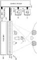
도 1은 실시예에 따른 대화형 3차원 디스플레이 장치의 전체적인 구성을 개략적으로 보여준다.
도 2는 실시예에 따른 대화형 3차원 디스플레이 장치의 블록도 및 신호 흐름을 보여준다.
도 3은 사용자의 의도와 시나리오를 매핑(Mapping)한 테이블을 예시적으로 보여준다.
도 4a는 화면 밖으로 빠져나간 객체 가장 가까운 화면 안쪽에 점 형태로 바운더리 커서를 표시하는 경우를 예시적으로 보여준다.
도 4b는 객체가 더 이상 화면 밖으로 이동하지 못하도록 홀드되는 상태를 화살표로 표시하는 경우를 예시적으로 보여준다.
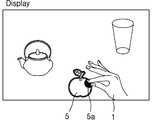
도 5는 손과 영상이 정합되게 화면에 표시되어, 손으로 가상 객체를 선택하는 예를 보여준다.
도 6은 손과 영상이 별도의 영역에 있을 경우, 손 모양의 커서를 사용하여 가상 객체를 선택하는 예를 보여준다.
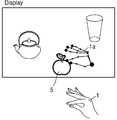
도 7은 가상 객체와 손 모양의 커서 사이를 연결하는 가상의 실(String)을 사용하여 가상 객체를 선택하는 예를 보여준다.
도 8은 실시예에 따른 대화형 3차원 디스플레이 장치에 홀로그래픽 3차원 디스플레이를 적용할 때의 광학적 구성의 일예를 개략적으로 보여준다.
도 9는 도 8의 광학적 구성으로 대화형 3차원 디스플레이 장치를 구현하기 위한 시스템 구성을 보인 블록도이다.
도 10은 실시예에 따른 대화형 3차원 디스플레이 장치에 적용되는 3차원 디스플레이의 다른 예를 예시적으로 보여준다.
도 11은 도 10의 3차원 디스플레이 구성을 개략적으로 보인 상면도이다.
도 12a 및 도 12b는 도 11의 3차원 디스플레이의 동작을 개략적으로 보여준다.
도 13은 실시예에 따른 대화형 3차원 디스플레이 방법을 개략적으로 보여준다.1 schematically shows an overall configuration of an interactive three-dimensional display device according to an embodiment.
2 shows a block diagram and signal flow of an interactive three-dimensional display device according to an embodiment.
FIG. 3 shows an example of a table mapping a user's intention and a scenario.
FIG. 4A illustrates a case where a boundary cursor is displayed in a point shape on the inner side of the screen closest to the object that has escaped from the screen.
FIG. 4B illustrates an example of a state where an object is held so as to be prevented from moving out of the screen by an arrow.
Fig. 5 shows an example in which a hand and an image are displayed on the screen so as to be matched, and a virtual object is selected by hand.
6 shows an example of selecting a virtual object using a hand cursor when the hand and the image are in different areas.
FIG. 7 shows an example of selecting a virtual object using a virtual string connecting a virtual object and a hand cursor.
FIG. 8 schematically shows an example of an optical configuration when a holographic three-dimensional display is applied to an interactive three-dimensional display device according to an embodiment.
9 is a block diagram showing a system configuration for implementing an interactive three-dimensional display device in the optical configuration of FIG.
FIG. 10 exemplarily shows another example of a three-dimensional display applied to an interactive three-dimensional display device according to the embodiment.
11 is a top view schematically showing the three-dimensional display configuration of FIG.
12A and 12B schematically illustrate the operation of the three-dimensional display of FIG.
13 schematically shows an interactive three-dimensional display method according to an embodiment.
이하, 첨부된 도면들을 참조하면서, 실시예에 따른 대화형 3차원 디스플레이 장치 및 방법을 상세히 설명한다. 도면에서 동일한 참조번호는 실질적으로 동일한 구성 요소를 지칭한다. 각 구성 요소의 크기나 두께 등은 설명의 편의를 위해 과장되어 있을 수 있다. 또한, 이하에 설명되는 실시예는 단지 예시적인 것에 불과하며, 이러한 실시예들로부터 다양한 변형이 가능하다.Hereinafter, an interactive 3D display apparatus and method according to an embodiment will be described in detail with reference to the accompanying drawings. In the drawings, like reference numerals refer to substantially the same elements. The size and thickness of each component may be exaggerated for convenience of explanation. Furthermore, the embodiments described below are merely illustrative, and various modifications are possible from these embodiments.
도 1은 실시예에 따른 대화형 3차원 디스플레이 장치의 전체적인 구성을 개략적으로 보여준다. 도 2는 실시예에 따른 대화형 3차원 디스플레이 장치의 블록도 및 신호 흐름을 보여준다.1 schematically shows an overall configuration of an interactive three-dimensional display device according to an embodiment. 2 shows a block diagram and signal flow of an interactive three-dimensional display device according to an embodiment.
도 1 및 도 2를 참조하면, 실시예에 따른 대화형 3차원 디스플레이 장치는, 사용자의 손(1)의 모양과 위치, 움직임 등을 감지하는 손 센싱 모듈(10)과, 인터페이스 처리장치(100)와, 영상 데이터에 따라 사용자가 의도한 가상 객체의 변화가 반영된 3차원 영상을 표시하는 3차원 디스플레이(200)를 포함한다. 실시예에 따른 대화형 3차원 디스플레이 장치는, 시청자의 눈 위치를 확인하는 눈 추적(Eye tracking) 모듈(30)을 더 포함할 수 있다. 여기서, 실시예에 따른 대화형 3차원 디스플레이 장치는, 눈 추적 모듈(30)을 적용하지 않을 수도 있다.1 and 2, an interactive three-dimensional display device according to an embodiment includes a
손 센싱 모듈(10)은 손의 위치와 모양 등을 감지하여 손영상을 확보하도록 마련된 것으로, 제스처 센서(Gesture Sensor:11)를 포함할 수 있다. 눈 추적 모듈(30)은 시청자의 눈 위치를 추적하도록 눈 추적 센서(31)를 포함할 수 있다.The
인터페이스 처리장치(100)에는 사용자 인터렉션 모듈(User Interaction Module:110), 영상 렌더링 모듈(Image Rendering Module:150) 등이 포함될 수 있다. 사용자 인터렉션 모듈(110)은 손 센싱 모듈(10)에서 획득한 손영상을 이용하여 사용자가 의도한 손의 정보를 분석하고, 분석된 결과를 미리 정의된 유저 인터페이스 시나리오와 비교하여 가상 객체를 조정할 파라미터를 생성하도록 마련될 수 있다. 영상 렌더링 모듈(150)은, 사용자 인터렉션 모듈(110)에서 생성된 파라미터에 따라 장면을 세팅하고 이를 렌더링하여 영상 데이터를 생성하고, 이로부터 3차원 디스플레이(200)를 위한 디스플레이 데이터(Display Data)를 생성할 수 있다.The
손 센싱 모듈(10), 눈 추적 모듈(30) 등의 하드웨어를 통해 수집된 데이터는 사용자 인터렉션 모듈(110) 및 영상 렌더링 모듈(150)에서 처리되고, 3차원 디스플레이(200)에 표시되는 영상에 반영될 수 있다. 여기서, 3차원 디스플레이(200)가 사용자 눈 추적 모듈(30)을 포함하는 경우, 데이터를 수집하는 하드웨어는 손의 위치 및 모양 등을 감지하는 손 센싱 모듈(10)뿐만 아니라, 눈 추적 모듈(30) 등도 포함할 수 있다. 도 1 및 도 2에서는 실시예에 따른 대화형 3차원 디스플레이 장치에 눈 추적 모듈(30)을 적용되어, 사용자의 눈(7)(9) 위치에 따라 장면 세팅부(160)에서 세팅되는 장면을 조정하도록 마련된 예를 보여준다. 다른 예로서, 실시예에 따른 대화형 3차원 디스플레이(200)장치는 사용자 눈 추적 모듈(30)을 포함하지 않도록 구현될 수도 있다. 이하에서는, 눈 추적 모듈(30)이 적용된 경우를 예를 들어 설명한다.The data collected through the hardware such as the
사용자 인터렉션 모듈(110)은, 손 센싱 모듈(10)에서 획득한 손영상을 이용하여 손(1)의 위치와, 모양, 움직임 등을 분석한다. 또한, 사용자 인터렉션 모듈(110)은 손영상을 분석된 결과를 미리 정의된 유저 시나리오와 비교하여 시청자의 의도를 파악하고 가상 객체를 조정할 파라미터를 생성한다. 이를 위하여, 사용자 인터렉션 모듈(110)은 손 위치/모양 분석부(120)와 유저 시나리오 검색 확인부(130)를 구비할 수 있다.The
도 2를 참조하면, 사용자 인터렉션 모듈(110)은 손영상을 이용하여 손(1)의 위치, 모양, 움직임 등을 분석하도록 손 위치/모양 분석부(120)를 포함할 수 있다. 손 위치/모양 분석부(120)는 손 위치 분석부(121)와 손 모양 분석부(125)를 구비할 수 있다. 손 위치/모양 분석부(120)는 손 위치 분석부(121)와 손 모양 분석부(125)가 통합된 구조로 마련될 수도 있다. 또한, 사용자 인터렉션 모듈(110)은, 유저 시나리오를 검색하고, 손 위치/모양 분석부(120)에서 분석된 결과를 유저 시나리오와 비교하여, 가상 객체를 조정할 파라미터를 생성하는 유저 시나리오 검색 확인부(130)를 포함할 수 있다. 사용자 인터렉션 모듈(110) 내에 유저 시나리오를 저장할 유저 시나리오 저장부(140)가 마련되거나, 별도로 마련된 저장부에 유저 시나리오가 저장될 수 있다. 도 2에서는 사용자 인터렉션 모듈(110) 내에 유저 시나리오 저장부(140)가 마련된 경우를 예시적으로 보여준다.Referring to FIG. 2, the
손 위치/모양 분석부(120)는, 손 센싱 모듈(10)에서 획득된 손영상으로부터, 손이나 손가락의 위치를 확인하고, 각 손가락의 모양을 인식하여, 손 모양, 손 모션 및 손이 움직이는 속도 중 적어도 하나를 파라미터화하도록 마련될 수 있다. 예를 들어, 손 위치/모양 분석부(120)는, 손 센싱 모듈(10)로부터 얻어지는 손영상을 분석하여 손 또는 손가락의 위치를 확인하고, 각 손가락의 모양을 인식하여, 예를 들어, 그랩(Grab), 릴리즈(Release) 모양, 이전 위치와 비교하여 손이 움직이는 속도 등을 파라미터화할 수 있다. 이러한 손 위치/모양 분석부(120)의 분석 결과는 유저 시나리오 검색 확인부(130)로 전달될 수 있다.The hand position /
이와 같이, 손 위치/모양 분석부(120)에서 파라미터화된 움직임(Gesture)은 유저 시나리오 검색 확인부(130)에서 미리 정의된 유저 시나리오와 비교하여 사용자의 의도를 파악하는데 사용될 수 있다. 정의된 유저 시나리오는 3차원(3D) 영상이 아닌 실제 물체를 다루는 것과 유사한 느낌을 가지도록 설계될 수 있다.As described above, the gesture parameterized in the hand position /
도 3은 사용자의 의도와 시나리오를 매핑(Mapping)한 테이블을 예시적으로 보여준다. 도 3에서와 같이, 사전에 정의된 유저 시나리오와 비교하여 확인된 사용자의 의도는 영상 렌더링 모듈(150)의 장면 세팅부(160)로 전달되어, 각 객체의 변화가 반영된 새로운 장면(Scene)을 구성하게 된다.FIG. 3 shows an example of a table mapping a user's intention and a scenario. As shown in FIG. 3, the intention of the user determined in comparison with the previously defined user scenario is transmitted to the
도 3을 참조하면, 예를 들어, 선택(Select)은 손가락을 릴리즈(Release) 한 상태에서 엄지를 포함한 2개 이상의 손가락이 닫히는 그랩(Grab)으로 바꾸는 것으로 표현할 수 있다. 병진 운동(Translation Motion)은 선택 상태의 손을 움직임(Move)으로써 표현할 수 있다. 또한, 움직이는 방향으로 가상 객체를 진행시키는 던지고 정지시키는(Throw & Stop) 모션은 선택 상태의 손으로 가상 객체를 움직이는 중간에 손을 펴고 손을 완전히 펴는 동작으로 표현할 수 있다. 스케일 조절은 선택 상태의 두 손의 간격을 조절하여 표현할 수 있다. 회전은 두 손을 주먹을 쥔 상태로 서로 다른 방향으로 움직여 표현할 수 있다. 화면상의 메뉴(On Screen Menu)는 검지 손가락을 위로 치켜들어 표현할 수 있다. 메뉴 선택(Menu Selection)은 메뉴 상에서 손가락을 스위핑(Swip)하거나 메뉴의 텍스트(Text)를 스위핑하여 표현할 수 있다. 오케이 및 취소(OK & Cancel)는 엄지를 위로 올리거나 내림으로써 표현할 수 있다. 도 3에 보인 유저 시나리오는 예시적인 것일 뿐, 실시예가 이에 한정되는 것은 아니며, 실시예에 따른 대화형 3차원 디스플레이(200)장치에 적용되는 유저 시나리오는, 사용되는 콘텐츠나 응용에 따라 다양하게 변형될 수 있다.Referring to FIG. 3, for example, a select can be expressed by changing a finger to a grab in which two or more fingers including a thumb are closed when the finger is released. The translation motion can be expressed by moving the hand of the selected state (Move). In addition, Throw & Stop motion, which advances a virtual object in the moving direction, can be expressed by extending the hand in the middle of moving the virtual object with the hand of the selected state and fully stretching the hand. Scaling can be expressed by adjusting the spacing of the two hands in the selected state. Rotation can be expressed by moving the two hands in different directions while holding their fists. The On Screen Menu can be expressed by pointing the index finger up. Menu Selection can be expressed by swiping a finger on the menu or sweeping the text of the menu. OK and Cancel can be expressed by raising or lowering the thumb. The user scenario shown in FIG. 3 is merely an example, and the embodiment is not limited thereto, and the user scenario applied to the interactive three-
다시 도 2를 참조하면, 영상 렌더링 모듈(150)은, 장면 세팅부(160)와, 가상 객체 렌더링부(170)와, 3차원 영상 부호화부(3D 영상 Encoding:180)를 포함할 수 있다.Referring again to FIG. 2, the
장면 세팅부(160)는, 사용자 인터렉션 모듈(110)의 유저 시나리오 검색 확인부(130)에서 생성된 가상 객체 조정 파라미터(145)를 전달받아, 가상 객체 데이터와 장면을 구성하는 각 객체 배경, 각 객체의 움직임을 고려한 장면을 세팅할 수 있다. 장면 세팅부(160)에는 눈 추적 모듈(30)에서 획득된 시청자의 눈 위치 데이터가 입력될 수 있다. 장면 세팅부(160)는 시청자의 눈 위치 데이터를 고려하여 장면을 세팅하도록 마련될 수 있다.The
한편, 3차원 디스플레이(200)의 경우, 시청자의 위치나 사용자 인터페이스 사용 도중에 객체가 화면 밖으로 나가 보이지 않게 되는 경우가 있을 수 있으므로, 이를 방지하거나 대응하기 위한 추가 시나리오가 필요하다.On the other hand, in the case of the three-
실시예에 따른 대화형 3차원 디스플레이 장치에 따르면, 사용자 제어에 의해 화면 경계 밖으로 영상이 사라지는 것을 방지하도록, 장면 세팅부(160)는 장면 바운더리 기능을 포함하도록 구성될 수 있다. 장면 바운더리 기능은, 바운더리 커서나, 객체의 경계 부분이 화면의 가장자리와 겹칠 때 객체의 이동을 금지하는 객체 홀드 기능으로 구현될 수 있다.According to the interactive three-dimensional display device according to the embodiment, the
예를 들어, 장면 세팅부(160)는, 화면 밖으로 객체가 빠져 나간 경우, 객체와 가장 가까운 화면 안쪽에 점 또는 다각형을 표시하여 그 방향으로 다른 객체가 있음을 표시하는 바운더리 커서를 표시하도록 마련될 수 있다. 도 4a는 화면 밖으로 빠져나간 객체 가장 가까운 화면 안쪽에 점(161) 형태로 바운더리 커서를 표시하는 경우를 예시적으로 보여준다. 이와 같이 바운더리 커서를 표시하도록 된 경우, 화면 밖 객체를 제어하기 위해, 사용자 인터렉션 모듈(110)을 사용하여 바운더리 커서(161)를 조작하도록 마련될 수 있다.For example, when the object is out of the screen, the
또한, 다른 방식으로, 장면 세팅부(160)는 화면에 보여야하는 객체가 화면을 벗어나려고 할 때, 마치 화면에 벽이 있는 것과 같은 효과를 주시 다시 안쪽으로 들어오도록 하거나, 객체의 경계 부분이 화면이 가장 자리와 겹치게 될 때 더 이상 객체가 이동하지 못하도록 객체를 홀드하도록 마련될 수 있다. 도 4b는 객체가 더 이상 화면 밖으로 이동하지 못하도록 홀드되는 상태를 화살표(163)로 표시하는 경우를 예시적으로 보여준다.Alternatively, when the object to be displayed on the screen is to be moved out of the screen, the
한편, 실시예에 따른 대화형 3차원 디스플레이 장치에 의해 형성되는 가상 객체 영상이 시청자(사용자)와 3차원 디스플레이(200) 화면 사이에 위치할 수도 있지만, 디스플레이 화면에서 멀리 표시될 수도 있다. 이와 같이, 3원 디스플레이 특성에 따라 사용자의 손이 닿을 수 있는 범위보다, 화면이 표현할 수 있는 영역이 더 크다.Meanwhile, the virtual object image formed by the interactive three-dimensional display device according to the embodiment may be located between the viewer (user) and the three-
따라서, 가상 객체 선택시, 손과 가상 객체가 완전히 정합되는 것은 한계가 있을 수 있다. 또한, 손이 화면 안에 있을 경우, 좀더 직관적이고 현실감이 있지만, 화면을 가릴 수도 있다.Therefore, when a virtual object is selected, there is a limitation that the hand and the virtual object are perfectly matched. Also, when the hand is in the screen, it may be more intuitive and realistic, but it may cover the screen.
이를 고려하여, 장면 세팅부(160)는 손의 모양과 위치를 화면에 표시하는 커서를 사용하도록 장면을 세팅할 수 있다. 손의 모양과 위치를 화면에 커서로 표시하도록 장면 세팅부(160)는 손 위치/모양 분석부(120)로부터 획득된 손의 모양, 위치, 움직임 등에 대한 정보가 입력될 수 있다. 손의 모양, 위치, 움직임에 대한 정보는 유저 시나리오 검색 확인부(130)를 거쳐 장면 세팅부(160)로 입력되거나 손 위치/모양 분석부(120)로부터 장면 세팅부(160)로 바로 입력될 수 있다. 도 2에서 손 위치/모양 분석부(120)로부터 획득된 손의 모양, 위치, 움직임에 대한 정보가 장면 세팅부(160)로 입력되는 경로는 생략되어 있다.In consideration of this, the
커서는 손 위치/모양 분석부(120)에서 얻어진 손 모양과 동일한 손 영상 커서로 표시되거나, 점과 선으로 이루어진 손 모양의 커서(도 4a의 165 참조)로 표시될 수 있다. 여기서, 손과 가상 객체가 정합되는 경우에도 사용시 오류 방지를 위해 커서를 사용할 수 있다.The cursor may be displayed with the same hand image cursor as that obtained by the hand position /
이와 같이, 장면 세팅부(160)는, 가상 객체 선택시, 손과 객체가 정합되는 방식으로 가상 객체를 선택하거나, 손 영상 형태의 커서나 점과 선으로 이루어진 손 모양의 커서(165)를 사용하여 가상 객체를 선택하도록 장면을 세팅할 수 있다.In this way, the
손과 가상 객체의 정합에 의해 가상 객체의 선택이 이루어지도록 장면을 세팅하는 경우, 손이 커서 역할을 할 수 있다. 여기서, 손과 객체의 정합이 가능한 경우에도, 오류 방지를 위해 손 모양의 커서를 화면에 표시하여 가상 객체의 선택이 커서를 이용해 이루어지도록 장면을 세팅할 수 있다. 이 경우에도 커서는 손 영상 커서이거나, 점과 선으로 이루어진 손 모양의 커서일 수 있다.When a scene is set so that a selection of a virtual object is made by matching a hand and a virtual object, a hand can act as a cursor. Here, even if the hand and the object can be matched, a hand cursor can be displayed on the screen to prevent errors, and the scene can be set so that the selection of the virtual object is performed using the cursor. In this case, the cursor may be a hand image cursor or a hand cursor formed of a point and a line.
또한, 손과 영상이 별도의 영역에 있는 경우, 손 모양의 커서를 사용하여 가상 객체의 선택이 이루어지도록 장면을 세팅할 수 있다. 이 경우, 장면 세팅부(160)는, 손 위치/모양 분석부(120)에서 얻어진 손의 위치 및 모양 정보에 따라, 화면에 손 모양의 커서가 표시되거나, 손 모양의 커서와 가상 객체 사이를 예를 들어, 가상의 실(string) 등을 사용하여 연결하도록 장면을 세팅할 수 있다. 이때, 손 모양의 커서는 손 영상으로 된 커서이거나 점과 선 등으로 이루어지고 손 모양으로 형상화된 커서일 수 있다.In addition, when the hand and the image are in a separate area, a scene can be set so that the selection of the virtual object is performed using a hand cursor. In this case, the
이와 같이, 실시예에 따른 대화형 3차원 디스플레이 장치에 따르면, 장면 세팅부(160)는 가상 객체의 위치에 따라 직접제어나 간접제어 방식 중 선택하여 가상 객체를 선택하도록 장면을 세팅할 수 있다.As described above, according to the interactive 3D display apparatus according to the embodiment, the
즉, 근거리 직접제어 방식으로 손과 가상 객체의 정합에 의해 가상 객체를 선택하거나, 커서를 이용하여 간접제어 방식으로 가상 객체를 선택하도록 장면이 세팅될 수 있다. 이때, 커서는 예를 들어, 제스처 센서(11)에서 감지된 손 영상을 그대로 사용하거나 이 손 영상과 동일한 손 모양으로 점과 선이 연결된 형태로 형성될 수 있다.That is, a scene may be set to select a virtual object by matching a hand and a virtual object by a near-direct control method, or to select a virtual object by an indirect control method using a cursor. At this time, the cursor may be formed by using the hand image sensed by the
한편, 장면 세팅부(160)는, 손 위치/모양 분석부(120)에서 얻어진 손의 위치 및 모양 정보를 이용하여, 가상 객체의 위치에 따라 가상 객체를 선택하는 도구의 선택이 자동으로 이루어지도록 장면을 세팅할 수 있다.On the other hand, the
예를 들어, 손과 영상이 정합 가능한 경우, 손이 커서 역할을 할 수 있으므로, 가상 객체를 선택하는 도구는 손일 수 있으며, 근거리 직접제어 방식으로 가상 객체를 선택할 수 있다.For example, when the hand and the image are matched, the hand may be large and the virtual object selection tool may be a hand, and the virtual object can be selected by the near direct control method.
또한, 손과 영상을 정합하는 대신에, 손과 영상이 별도의 영역에 위치하는 경우, 손 모양의 커서를 사용하여 가상 객체를 선택하도록 장면을 세팅할 수 있다.Also, instead of matching the hand and the image, if the hand and the image are located in different areas, a scene can be set to select a virtual object using a hand cursor.
또한, 3차원 디스플레이(200)로 화면보다 먼 곳에 영상이 표현되어, 손과 영상이 별도의 영역에 위치하여, 손과 영상이 직접적으로 인터렉션 하기 어려운 경우, 가상 객체와 손 모양 커서 사이를 연결하는데 가상의 실(String) 등을 사용하도록 장면을 세팅할 수 있다.In addition, when the image is displayed farther than the screen by the three-
이와 같이, 손과 영상이 별도의 영역에 위치하는 경우, 가상 객체를 선택하는 도구는 손 모양 커서일 수 있으며, 원거리 간접제어 방식으로 가상 객체를 선택할 수 있다.In this way, when the hand and the image are located in different areas, the tool for selecting the virtual object can be a hand cursor, and the virtual object can be selected by the remote indirect control method.
이상에서와 같이, 장면 세팅부(160)는, 가상 객체의 위치에 따라, 손과 객체가 같은 영역에 위치할 때 손과 객체를 정합하는 방식으로 가상 객체를 선택하거나, 손과 객체가 별도의 영역에 위치하거나 손과 객체 사이의 거리가 먼 경우 가상 객체 선택에 커서를 이용하는 것을 자동으로 결정하도록 마련될 수 있다.As described above, the
이를 위해, 장면 세팅부(160)는 손 위치/모양 분석부(120)에서 얻어진 손의 위치 및 모양 정보로부터 손과 객체가 정합하는지 여부를 먼저 판단한 다음, 정합 여부에 따라 가상 객체를 선택하는 도구를 결정하여 장면을 세팅할 수 있다.To this end, the
도 5는 손과 영상이 정합되어, 손(1)으로 가상 객체를 선택하는 예를 보여준다. 도 5에서와 같이, 손(1)과 가상 객체(5)가 정합되는 경우, 선택된 가상 객체(5)의 외각선은 예를 들어, 하이라이트(Highlight)되거나 선택된 객체의 톤(Tone)을 조절하여 선택 여부를 표시할 수 있다. 또한, 선택된 객체(5)와 손이 만나는 부분(1)에 다른 색상의 다각형 또는 폐곡선을 표시하여 인터렉션의 정확도를 높일 수 있다. 도 5에서는 선택된 객체(5)와 손(1)이 만나는 부분(5a)이 하이라이트되어 선택을 표시하는 예를 보여준다.5 shows an example in which a hand and an image are matched and a virtual object is selected by the
도 6은 손(1)과 영상이 별도의 영역에 있을 경우, 점과 선으로 이루어진 손 모양 커서(1a)를 사용하여 가상 객체(5)를 선택하는 예를 보여준다. 도 6에서와 같이, 손(1)과 영상이 별도의 영역에 있는 경우, 점과 선으로 이루어진 손 모양 커서(1a) 등을 사용할 수 있다. 이때, 손 모양 커서(1a)는 점과 선으로 이루어져 손 모양과 위치를 파악할 수 있도록 형성될 수 있다. 점과 선 등으로 이루어진 손 모양 커서를 사용하는 경우에도, 선택된 가상 객체(5)의 외각선은 하이라이트(Highlight)되거나 선택된 객체의 톤(Tone)을 조절하여 선택 여부를 표시할 수 있다. 또한, 선택된 객체(5)와 손 모양 커서(1a)가 만나는 부분에 다른 색상의 다각형 또는 폐곡선을 표시하여 인터렉션의 정확도를 높일 수 있다. 도 6에서 손 모양 커서(1a)를 점과 선으로 나타내었지만, 손 모양 커서(1a)는 손영상으로 이루어지거나 다른 다양한 형태로 변형 가능하다. 또한, 주먹, 그랩(Grab), 릴리즈(Release) 등 2개 이상의 손 모양을 대변하도록 커서의 위치를 표현할 수 있다.6 shows an example in which the
한편, 3차원 디스플레이(200)의 경우, 화면 앞쪽으로 나온 영상도 표현이 가능하지만, 필요에 따라 화면보다 먼 곳에 있는 영상도 표현 가능하다. 하지만, 이 경우에는, 손(1)과 영상을 직접적으로 인터렉션 하기는 어렵다. 이 경우 커서를 이용하지만, 영상이 아주 멀리 떨어져 있는 경우에는 커서만으로는 사용이 어려울 수 있다. 이러한 경우에는, 도 7에서와 같이, 가상 객체(5)와 손 모양 커서(1a) 사이를 연결하는 가상의 실(String:2) 등을 사용하여 가상 객체(5)를 선택하도록 장면을 세팅할 수도 있다. 도 7은 가상 객체(5)와 손 모양 커서(1a) 사이를 연결하는 가상의 실(2)을 사용하여 가상 객체(5)를 선택하는 예를 보여준다. 도 7에서 손 모양 커서(1a)는 점과 선 등으로 이루어지는 대신에 손 영상으로 이루어지거나 다양한 형태로 이루어질 수 있다.On the other hand, in the case of the three-
이와 같이, 실시예에 따른 대화형 3차원 디스플레이 장치에 따르면, 손 위치, 모양, 움직임의 센싱 결과를 객체의 위치에 따라 유저 인터페이스 시나리오와 비교 분석하여 손과 영상이 정합되는 근거리 직접 제어에 의해 가상 객체를 선택하거나, 손과 영상이 별도의 영역에 위치하며 커서로 가상 객체를 선택하거나 커서와 가상의 실로 연결하는 방식으로 가상 객체를 선택할 수 있다.As described above, according to the interactive three-dimensional display device according to the embodiment, the sensing result of the hand position, shape, and motion is compared with the user interface scenario according to the position of the object, You can select an object, or a virtual object can be selected by placing the hand and the image in separate areas and selecting the virtual object with the cursor or connecting the cursor to the virtual room.
다시 도 2를 참조하면, 가상 객체 렌더링부(170)는, 장면 세팅부(160)에 의해 세팅된 장면을 렌더링하여 영상 데이터를 획득할 수 있다. 가상 객체 렌더링부(170)에서 획득되는 영상 데이터는 1장 이상의 2차원 영상 데이터 또는 깊이 데이터(Depth Data)로 렌더링될 수 있다. 또한, 가상 객체 렌더링부(170)에서 영상 데이터를 획득하기 위해 입력되는 3차원 입력 데이터는 복셀 데이터, 칼라 및 깊이 영상 데이터, 3차원 메쉬 데이터 등이 사용될 수 있다. 이와 같이, 가상 객체 렌더링부(170)에서 영상 데이터를 획득하기 위해 입력되는 3차원 입력 데이터는 3차원 디스플레이(200)의 광학적 특성에 맞도록 재조정될 수 있다.Referring again to FIG. 2, the virtual
3차원 영상 부호화부(180)는 가상 객체 렌더링부(170)에서 획득된 영상 데이터를 디지털화하여 사용자가 의도한 가상 객체의 변화가 반영된 3차원 영상을 표시하기 위한 3차원 디스플레이 데이터를 생성할 수 있다.The 3D
이와 같이 생성된 디스플레이 데이터는 3차원 디스플레이(200)로 전달되어, 공간광변조기(250)를 통해 사용자가 의도한 가상 객체의 변화가 반영된 3차원 영상으로 표현될 수 있다.The generated display data is transferred to the three-
다시 도 1을 참조하면, 3차원 디스플레이(200)는, 공간광변조기(SLM:250), 공간광변조기(250)에 빛을 비추기 위한 조명유닛을 포함할 수 있다. 조명유닛은 광원(210)과, 이 광원(210)으로부터 출사된 광을 확대하여 공간광변조기(250) 전체에 비추는 조명 광학계(230)를 포함할 수 있다. 광원(210)에서 나온 빛은 조명 광학계(230)에 의해 확대되어 공간광변조기(250)의 크기보다 큰 면적으로 전환될 수 있다. 공간광변조기(250)는 여러개의 화소로 구성되는 것으로, 3차원 영상을 구현하기 위해, 각 화소의 밝기나 위상이 제어되며, 이 값들은 앞에서 설명한 인터페이스 처리장치(100)를 통해 미리 계산될 수 있다. 인터페이스 처리장치(100)에서 계산된 디스플레이 데이터(Display data)는 공간광변조기(250)를 구동하도록 입력될 수 있다.Referring again to FIG. 1, the three
공간광변조기(250)는 입사광의 위상을 변조하는 위상 변조기 또는 입사광의 밝기를 변조하는 진폭 변조기일 수 있으며, 또는 입사광의 위상과 밝기를 모두 변조하는 복합 변조기일 수도 있다. 공간광변조기(250)에 의해 변조된 빛은 회절 및 간섭에 의해 공간상의 소정 위치에 입체 영상을 형성할 수 있다.The spatial
이러한 공간광변조기(250)는 디스플레이 데이터에 따라 구동되어, 사용자가 의도한 가상 객체의 변화가 반영된 3차원 영상을 표시할 수 있다.The spatial
실시예에 따른 대화형 3차원 디스플레이 장치를 구현하기 위해, 3차원 디스플레이(200)로는 예를 들어, 양안 깊이 신호(Binocular Depth Cue)와 병행하여 초점정보(Accommodation)까지 구현되는 홀로그래픽 3차원 디스플레이(200)(Holographic 3D Display)가 적용될 수 있다. 이외에도 실시예에 따른 대화형 3차원 디스플레이 장치를 구현하기 위해, 3차원 디스플레이(200)로는, 양안식 3차원 디스플레이, 라이트 필드방식(Light Field) 3차원 디스플레이(200) 등이 적용될 수 있다.In order to realize the interactive three-dimensional display device according to the embodiment, the three-
도 8은 실시예에 따른 대화형 3차원 디스플레이 장치에 홀로그래픽 3차원 디스플레이(200)를 적용할 때의 광학적 구성의 일예를 개략적으로 보여주며, 도 9는 도 8의 광학적 구성으로 대화형 3차원 디스플레이 장치를 구현하기 위한 시스템 구성을 보인 블록도이다. 도 8은 실시예에 따른 대화형 3차원 디스플레이 장치가, 홀로그래픽 3차원 디스플레이(200)를 사용하면서, 사용자의 눈 위치를 추적하여 계산량을 줄이도록 구현된 예를 보여준다.FIG. 8 schematically shows an example of the optical configuration when the holographic three-
도 8 및 도 9를 참조하면, 실시예에 따른 대화형 3차원 디스플레이 장치는, 눈 추적 센서(31), 3차원 디스플레이(200), 제스처 센서(11) 등을 포함할 수 있다. 또한, 실시예에 따른 대화형 3차원 디스플레이 장치는, 눈 추적 센서(31)를 포함하는 눈 추적 모듈(30), 제스처 센서(11)를 포함하는 손 센싱 모듈(10), 인터페이스 처리장치(100)를 포함할 수 있다. 눈 추적 센서(31)는 시야 영역(Viewing Area) 안에 있는 시청자의 얼굴을 향하도록 구성되는 것으로, 이 눈 추적 센서(31)를 이용해 획득된 데이터(A)는 눈 추적 모듈(30)에서 분석되어 사용자의 눈 위치를 확인하는데 사용될 수 있다.8 and 9, the interactive three-dimensional display device according to the embodiment may include an
도 8에 도시된 바와 같이, 3차원 디스플레이(200)는 예를 들어, 조명유닛과 공간광변조기(250)를 포함할 수 있다. 또한, 3차원 디스플레이(200)는 조명유닛과 공간광변조기(250) 사이에 필드 렌즈(240)를 더 포함할 수 있다. 조명유닛은 예를 들어, 좌안용 조명유닛과 우안용 조명유닛을 포함할 수 있다. 좌안용 조명유닛은, 좌안용 광원(210a), 좌안용 조명 광학계(230a)를 포함할 수 있으며, 좌안용 조명 광학계(230a)는 좌안용 빔 편향기(231a), 제1조명 렌즈(233a)를 포함할 수 있다. 우안용 조명유닛은, 우안용 광원(210b) 및 우안용 조명 광학계(230b)를 포함할 수 있으며, 우안용 조명 광학계(230)는 우안용 빔 편향기(231b), 제2조명 렌즈(233b)를 포함할 수 있다.As shown in FIG. 8, the three-
좌안용 광원(210a) 및 우안용 광원(210b)은 광원 제어부(Light Source Controller:215)의 제어신호(C)에 따라 좌안용 조명광, 우안용 조명광을 출사한다. 빔 편향 제어부(Beam Deflection Controller:232)는 눈 추적 모듈(Eye Tracking Module:30)에서 획득된 눈 위치 데이터를 이용하여 좌안용 빔 편향기(231a)와 우안용 빔 편향기(231b)를 제어하여, 좌안용 광원(210a) 및 우안용 광원(210b)에서 출사된 빛의 방향을 제어한다. 좌안용 빔 편향기(231a)와 우안용 빔 편향기(231b)는 빔 편향 제어부(232)의 제어신호(B)에 따라 좌안용 조명광과 우안용 조명광의 진행 방향을 조절한다. 좌안용 조명광 및 우안용 조명광은 제1조명 렌즈(233a)와 제2조명 렌즈(233b) 등의 광학소자를 통해 공간광변조기(250)를 비출 수 있도록 방향이 변경되고 크기가 확대될 수 있다. 제1조명 렌즈(233a) 및 제2조명 렌즈(233b)로는 에프-세타 렌즈 등을 구비할 수 있으며, 이외에도 원하는 조명광을 만들 수 있는 다양한 종류의 렌즈가 적용될 수 있다. 제1조명 렌즈(233a) 및 제2조명 렌즈(233b)에 의해 확대된 빛은 필드 렌즈(240)를 통해 눈 방향으로 모아지도록 조정될 수 있다.The left eye
공간광변조기(250)는 입력되는 디스플레이 데이터(E)에 따라 구동되어, 입체 영상을 형성하고, 이와 같이 형성된 입체 영상이 시역(Viewing Area) 내에서 시청자(6)의 눈(6a)에 보여지게 된다.The spatial
이때, 제스처 센서(11)는 손 제스처 센싱 영역(Hand Gesture Sensing Region)에서의 손(1)의 위치와 모양을 감지한 손 영상(D)을 손 위치/모양 분석부(Hand Position/Shape:120)로 전달하게 된다. 제스처 센서(11)로는 씨모스 이미지 센서나, ToF 깊이 센서(ToF Depth sensor) 등을 사용할 수 있다.At this time, the
손 위치/모양 분석부(120)에서는 손 또는 손가락의 위치를 확인하고, 각 손가락의 모양을 인식하여, 손가락의 그랩, 릴리즈 모양과 이전 위치와 비교하여 손이 움직이는 속도 등을 파라미터화하고, 이와 같이 파라미터화된 손의 제스처는 시나리오 검색/확인부(130)에서 미리 정의된 유저 인터페이스 시나리오(UI Scenario)와 비교하여 사용자의 의도를 파악하게 된다. 이와 같이 파악된 사용자의 의도는 장면 세팅부(160)로 전달되고, 아울러 눈 추적 결과도 장면 세팅부(160)로 전달되어, 장면 세팅(Scene Setting)에 사용될 수 있다. 세팅된 장면은 가상 객체 렌더링부(170)에서 렌더링(Redering)되어 영상 데이터로 획득되고, 영상 데이터는 홀로그래픽 데이터 생성부(175)로 입력된다. 홀로그래픽 데이터 생성부(175)는 입력된 영상 데이터로부터 홀로그래픽 데이터를 생성(CGH Generation)하고, 3차원 영상 부호화부(180)에서 디스플레이 데이터를 생성하기 위한 부호화(Display Encoding)를 수행하여, 3차원 홀로그래픽 입체 영상을 형성하기 위한 디스플레이 데이터를 생성하게 된다. 이와 같이 생성된 디스플레이 데이터(E)는 공간광변조기(250)로 입력되어, 사용자의 의도에 따라 객체의 움직임이 반영된 홀로그래픽 입체 영상이 형성되어 시청자(6)의 눈(6a)에 보여지게 된다.The hand position /
도 8 및 도 9에서와 같이, 3차원 디스플레이(200)로 홀로그래픽 디스플레이를 사용하는 경우, 홀로그래픽 입체 영상을 형성하도록 공간광변조기(250)로 입력되는 디스플레이 데이터를 얻기 위해, 렌더링된 영상 데이터로부터 홀로그래픽 데이터를 생성하는 홀로그래픽 데이터 생성부(175)가 더 구비될 수 있다. 또한, 사용자의 눈 위치를 추적하여 계산량을 줄이도록 된 경우, 눈 추적 센서(31) 및 이를 포함하는 눈 추적 모듈(30)을 더 구비할 수 있으며, 추적된 눈 위치에 따라 조명광이 조사되는 방향으로 조절하도록, 빔 편향 제어부(232) 및 빔 편향기(231a)(231b) 등이 더 구비될 수 있다. 도 8 및 도 9에서는 눈 추적 센서(31)의 신호(A)가 눈 추적 모듈(30)로 입력되는 것이 도시되어 있으나, 눈 추적 센서(31)는 눈 추적 모듈(30) 내에 포함될 수 있다. 다른 예로서, 눈 추적 모듈(30)은 눈 추적 센서(31)에서 입력되는 신호(A)로부터 눈 위치를 산출하는 처리부만을 포함할 수도 있다.8 and 9, when a holographic display is used as the three-
도 2와 도 9의 비교로부터 알 수 있는 바와 같이, 홀로그래픽 데이터 생성부(175)는 가상 객체 렌더링부(170)와 3차원 영상 부호화부(180) 사이에 구비될 수 있다. 홀로그래픽 데이터 생성부(175)는 가상 객체 렌더링부(170)나 3차원 영상 부호화부(180)에 포함될 수도 있다.As can be seen from a comparison between FIG. 2 and FIG. 9, the
한편, 이상에서는 실시예에 따른 대화형 3차원 디스플레이 장치에 적용되는 3차원 디스플레이(200)가 좌안용 영상과 우안용 영상을 형성하도록 마련된 경우를 예를 들어 설명 및 도시하였는데, 이외에도 다양한 3차원 디스플레이가 적용될 수 있다.In the meantime, the case where the three-
예를 들어, 실시예에 따른 대화형 3차원 디스플레이 장치에는 다시점 영상을 형성하는 3차원 디스플레이가 적용될 수도 있다.For example, a three-dimensional display for forming a multi-view image may be applied to the interactive three-dimensional display device according to the embodiment.
도 10은 실시예에 따른 대화형 3차원 디스플레이 장치에 적용될 수 있는 3차원 디스플레이(500)의 다른 예를 예시적으로 보여준다. 도 11은 도 10의 3차원 디스플레이(500) 구성을 개략적으로 보인 상면도이다. 도 12a 및 도 12b는 도 11의 3차원 디스플레이(500)의 동작을 개략적으로 보여준다.Fig. 10 exemplarily shows another example of a three-
도 10 및 도 11을 참조하면, 실시예에 따른 3차원 디스플레이(500)는 광원(510), 투사용 광학소자(530), 홀로그래픽 광학소자(Holographic Optical Element, HOE:520), 공간광변조기(550)를 포함할 수 있다.10 and 11, a three-
광원(510)으로는 레이저와 같은 레이저와 같은 가간섭성 광원을 구비할 수 있다. 투사용 광학소자(530)는 광원(510)에서 방출된 빛을 포커싱한다. 홀로그래픽 광학소자(520)는 광원(510)과 투사용 광학소자(530) 사이에 배치될 수 있다. 공간광변조기(550)는 공간 상의 소정 위치에 입체 영상이 형성되도록 입사광을 변조한다. 광원(510), 홀로그래픽 광학소자(520), 및 투사용 광학소자(530)는 조명 유닛을 구성한다.The
투사용 광학소자(530)는 예를 들어, 오목한 반사면을 갖는 타원체 거울일 수 있다. 여기서, 굴절 렌즈나 회절 렌즈와 같은 다른 광학소자를 투사용 광학소자(530)로 사용할 수 있다. 도 10의 실시예에서, 투사용 광학소자(530)는 초점 평면(f) 상에 빛을 수렴시키는 역할을 할 수 있다. 여기서, 투사용 광학소자(530)는 광원(510)에서 방출된 빛을 평행빔으로 바꾸어주도록 마련될 수 있으며, 평행빔을 초점 평면 상에 포커싱하도록 포커싱용 투사용 광학소자를 하나 더 구비할 수도 있다. 이때, 포커싱용 투사용 광학소자로는 일반적인 굴절렌즈, 프레넬 렌즈, 홀로그래픽 렌즈 등이 적용될 수 있다.The transmitting
홀로그래픽 광학소자(520)에는 광원(510) 예컨대, 가간섭성 광원에서 방출된 빛을 회절시켜 투사용 광학소자(530)에 제공하도록 형성된 간섭 패턴이 형성될 수 있다. 이러한 홀로그래픽 광학소자(520)의 간섭 패턴은 투사용 광학소자(530)의 수차를 상쇄할 수 있는 역수차 정보를 담고 있어서, 공간광변조기(550)를 통해 형성되는 영상의 품질을 향상시킬 수 있다. 예를 들어, 광원(510)에서 방출된 빛은 평면 거울을 통해 홀로그래픽 광학소자(520)의 상부면으로 입사할 수 있다. 그런 후, 홀로그래픽 광학소자(520) 내에 형성된 간섭 패턴에 의해 회절된 빛이 홀로그래픽 광학소자(520)의 하부면으로 나올 수 있다. 이렇게 회절된 빛은 투사용 광학소자(530)의 수차와 상반되는 수차를 갖기 때문에, 투사용 광학소자(530)에 의해 초점 평면(f) 상에 포커싱될 때 수차가 없는 상태로 될 수 있다.The holographic
여기서, 광원(510)에서 방출된 빛을 홀로그래픽 광학소자(520)로 전달하기 위해, 평면 거울을 사용하지 않고 프리즘, 광섬유 등과 같은 다른 광전달 수단을 사용할 수도 있으며, 홀로그래픽 광학소자(520)의 상부면을 직접 향하도록 광원(510)이 배치될 수도 있다.Here, in order to transmit the light emitted from the
도 10의 측면도에는 단지 하나의 홀로그래픽 광학소자(520)만이 도시되어 있지만, 도 11에서와 같이, 3차원 디스플레이(500)에서 제공되는 입체 영상의 시점(view-point)의 개수에 따라 다수의 홀로그래픽 광학소자들이 배열될 수 있다.10, only one holographic
도 11을 참조하면, 투사용 광학소자(530)의 상부에 다수의 홀로그래픽 광학소자(520a~520g)들이 투사용 광학소자(530)의 광축(OX)에 수직한 방향을 따라 배열될 수 있다. 또한, 홀로그래픽 광학소자(520a~520g)의 각각에 대응하여 다수의 광원(510a~510g)들이 배치될 수 있다. 홀로그래픽 광학소자(520a~520g)들의 개수는 3차원 디스플레이(500)에서 제공되는 입체 영상의 시점의 개수와 같을 수 있다. 도 11에는 7개의 홀로그래픽 광학소자(520a~520g)와 7개의 광원(510a~510g)들이 예시적으로 도시되어 있지만, 이에 한정되는 것은 아니며 시점의 개수에 따라 달라질 수 있다. 또한, 시점의 개수와 관계없이 단지 하나의 홀로그래픽 광학소자를 사용하는 것도 가능하다. 예를 들어, 투사용 광학소자(530)의 광축(OX)에 수직한 방향을 따라 길게 연장된 하나의 홀로그래픽 광학소자를 사용하는 것도 가능하다.Referring to Figure 11, a plurality of holographic
다수의 광원(510a~510g)들 대신에 단지 하나의 광원을 사용할 수도 있다. 예를 들어, 빔스플리터 등을 이용하여 하나의 광빔을 다수의 광빔으로 나누어 홀로그래픽 광학소자(520a~520g)들에 제공할 수 있다. 이 경우, 각각의 홀로그래픽 광학소자(520a~520g)의 광입사면에 광의 투과/차단을 제어하는 광셔터가 배치될 수 있다. 또한, 각각의 광원(510, 510a~510g)은, 예를 들어, 적색 발광 레이저, 녹색 발광 레이저 및 청색 발광 레이저를 각각 포함할 수 있다. 이러한 적색 발광 레이저, 녹색 발광 레이저 및 청색 발광 레이저를 이용하여 광원(510, 510a~510g)은 백색 가시광을 제공할 수 있다.Only one light source may be used in place of the plurality of
다시 도 11을 참조하면, 제1광원(510a)에서 방출된 빛은 제 1 홀로그래픽 광학소자(520a)와 투사용 광학소자(530)를 통해 초점 평면 상의 시점 A에 포커싱될 수 있다. 또한, 제4광원(510d)에서 방출된 빛은 제 4 홀로그래픽 광학소자(520d)와 투사용 광학소자(530)를 통해 초점 평면 상의 시점 D에 포커싱될 수 있으며, 제7광원(510g)에서 방출된 빛은 제 7 홀로그래픽 광학소자(520g)와 투사용 광학소자(530)를 통해 초점 평면 상의 시점 G에 포커싱될 수 있다. 따라서, 다수의 광원(510a~110g) 중에서 어느 하나를 턴온시킴으로써 원하는 시점에 영상을 형성할 수 있다.Referring again to FIG. 11, the light emitted from the
투사용 광학소자(530)의 초점은 광축(OX) 상의 시점 D에 위치하고 있으므로, 초점에서 멀어지는 시점 G나 시점 A에 형성되는 영상은 투사용 광학소자(530)의 수차에 의해 크게 왜곡될 수 있다. 본 실시예에 따르면, 홀로그래픽 광학소자(520a~520g)들을 이용하여 투사용 광학소자(530)의 수차를 상쇄시킬 수 있기 때문에, 시점 G나 시점 A에 형성되는 영상도 수차에 의한 영향을 받지 않을 수 있다. 따라서, 본 실시예에 따른 3차원 디스플레이(500)는 수차 없이 넓은 면적에 영상을 형성할 수 있으며, 수차를 제거하기 위한 별도의 광학계가 필요 없기 때문에 그 크기도 작아질 수 있다.Since the focal point of the transmitting
도 12a 및 도 12b는 3차원 디스플레이(500)의 예시적인 동작을 보이는 상면도이다. 도 12a 및 도 12b를 참조하면, 예를 들어 시청자의 두 눈이 시점 C와 시점 E에 위치하고 있는 경우, 제3광원(510c)과 제5광원(510e)을 번갈아 온/오프시킬 수 있다. 그리고, 공간 광변조기는 제3 및 제5광원(510c, 510e)의 온/오프 주기에 동기하여 시청자의 좌안과 우안에서 각각 보이는 두 시점의 영상을 번갈아 형성하도록 동작할 수 있다. 그러면, 도 12a에 도시된 바와 같이 시청자의 우안에 시점 E의 영상을 제공하는 동작과, 도 12b에 도시된 바와 같이 시청자의 좌안에 시점 C의 영상을 제공하는 동작을 반복할 수 있다. 이에 따라, 시청자는 입체감 있는 영상을 감상할 수 있다. 시청자가 다른 위치로 이동하더라도 눈의 위치를 파악하여 가간섭성 광원(510a~110g)과 공간 광변조기의 동작을 제어할 수 있다.12A and 12B are top views showing exemplary operation of the three-
도 10 내지 도 12c는 실시예에 따른 대화형 3차원 디스플레이 장치에 적용될 수 있는 다시점 영상을 형성하는 3차원 디스플레이의 일예를 보인 것으로, 실시예가 이에 한정되는 것은 아니며, 실시예에 따른 대화형 3차원 디스플레이 장치에 다양한 다시점 영상을 형성하는 3차원 디스플레이가 적용될 수 있다.FIGS. 10 to 12C illustrate an example of a three-dimensional display for forming a multi-view image that can be applied to the interactive three-dimensional display device according to the embodiment, and the embodiments are not limited thereto. A three-dimensional display for forming various multi-view images on a 3D display device can be applied.
이상에서는 몇몇 실시예를 예시적으로 설명하였으나, 이외에도 다양한 3차원 디스플레이가 실시예에 따른 대화형 3차원 디스플레장치에 적용될 수 있다.Although several exemplary embodiments have been described above, various other three-dimensional displays can be applied to the interactive three-dimensional display device according to the embodiment.
이상에서 설명한 바와 같은 실시예에 따른 대화형 3차원 디스플레장치에 따르면, 사용자가 의도한 가상 객체의 변화가 반영된 3차원 입체 영상을 형성할 수 있으며, 사용자가 의도한 가상 개체를 선택할 수 있으며, 위치나 크기 등을 조정할 수 있다.According to the interactive 3D display apparatus of the embodiment as described above, it is possible to form a three-dimensional stereoscopic image reflecting the change of the virtual object intended by the user, to select the virtual object intended by the user, You can adjust the size and size.
도 13은 실시예에 따른 대화형 3차원 디스플레이 장치를 이용하여 사용자가 의도한 가상 객체의 변화가 반영된 3차원 입체 영상을 형성하는 과정을 개략적으로 보여준다.FIG. 13 schematically shows a process of forming a three-dimensional stereoscopic image in which a change of a virtual object intended by a user is reflected using an interactive three-dimensional display device according to an embodiment.
대화형 3차원 디스플레이를 구현하기 위해, 먼저, 제스처 센서(51)로 사용자의 손을 감지하여 손 영상을 획득한다(S100). 획득된 손영상을 이용하여 손의 정보를 분석하고 이 분석 결과를 미리 정의된 유저 시나리오와 비교하여 가상 객체를 조정할 파라미터를 생성한다(S200). 생성된 파라미터에 따라 장면을 세팅하고, 세팅된 장면을 렌더링하여 영상 데이터를 생성한다(S300). 3차원 디스플레이(200)를 통해 영상 데이터에 따라 사용자가 의도한 가상 객체의 변화가 반영된 3차원 입체 영상을 형성할 수 있다(S400).In order to realize an interactive three-dimensional display, first, a hand image is obtained by sensing a user's hand with a gesture sensor 51 (S100). The hand information is analyzed using the obtained hand image, and the analysis result is compared with a predefined user scenario to generate a parameter for adjusting the virtual object (S200). The scene is set according to the generated parameters, and the set scene is rendered to generate image data (S300). The
Claims (20)
Translated fromKorean상기 손 센싱 모듈에서 획득한 손영상을 이용하여 사용자가 의도한 손의 정보를 분석하고, 분석된 결과를 미리 정의된 유저 시나리오와 비교하여 가상 객체를 조정할 파라미터를 생성하는 사용자 인터렉션 모듈과;
상기 생성된 가상 객체 조정 파라미터에 따라 장면을 세팅하고 이를 렌더링하여 영상 데이터를 생성하고, 이를 디스플레이 데이터로 변환하는 영상 렌더링 모듈과;
상기 디스플레이 데이터에 따라 사용자가 의도한 가상 객체의 변화가 반영된 3차원 영상을 표시하는 3차원 디스플레이;를 포함하는 대화형 3차원 디스플레이 장치.A hand sensing module for sensing a hand of a user and acquiring a hand image;
A user interaction module for analyzing information of a user's intended hand using the hand image acquired by the hand sensing module and generating a parameter for adjusting a virtual object by comparing the analyzed result with a predefined user scenario;
An image rendering module for setting a scene according to the generated virtual object adjustment parameter and rendering the scene, generating image data, and converting the generated image data into display data;
And a three-dimensional display for displaying a three-dimensional image reflecting a change of a virtual object intended by the user according to the display data.
상기 손의 위치 및 모양, 움직임을 분석하는 손 위치/모양 분석부와;
상기 미러 정의된 유저 시나리오를 검색하고 상기 손 위치/모양 분석부의 분석 결과를 유저 시나리오와 비교하여, 가상 객체를 조정할 파라미터를 생성하는 유저 시나리오 검색 확인부;를 포함하는 대화형 3차원 디스플레이 장치.2. The user interaction module of claim 1,
A hand position / shape analyzer for analyzing the position, shape and motion of the hand;
And a user scenario retrieval confirmation unit for retrieving the mirror defined user scenario and comparing the analysis result of the hand position / shape analysis unit with the user scenario to generate a parameter for adjusting the virtual object.
손이나 손가락의 위치를 확인하고, 각 손가락의 모양을 인식하여, 손 모션 및 손이 움직이는 속도 중 적어도 하나를 파라미터화하는 대화형 3차원 디스플레이 장치.The hand position / shape analyzer according to claim 2,
An interactive three-dimensional display device for identifying a position of a hand or a finger, recognizing a shape of each finger, and parameterizing at least one of a hand motion and a speed at which the hand moves.
상기 사용자 인터렉션 모듈에서 생성된 가상 객체 조정 파라미터를 전달받아, 가상 객체 데이터와 장면을 구성하는 각 객체 배경, 각 객체의 움직임을 고려한 장면을 세팅하는 장면 세팅부와;
상기 장면 세팅부에서 세팅된 장면을 렌더링하여 영상 데이터를 획득하는 가상 객체 렌더링부와;
획득된 상기 영상 데이터를 디지털화하여 사용자가 의도한 가상 객체의 변화가 반영된 3차원 영상을 표시하기 위한 3차원 디스플레이 데이터를 생성하는 3차원 영상 부호화부;를 포함하는 대화형 3차원 디스플레이 장치.The apparatus of claim 1, wherein the image rendering module comprises:
A scene setting unit configured to receive a virtual object adjustment parameter generated by the user interaction module and set a scene considering virtual object data and background of each object constituting a scene and motion of each object;
A virtual object rendering unit for rendering a scene set by the scene setting unit and acquiring image data;
And a three-dimensional image encoding unit for generating three-dimensional display data for displaying a three-dimensional image reflecting the change of the virtual object intended by the user by digitizing the acquired image data.
객체가 화면 밖으로 사라지지 않도록, 장면 바운더리 기능을 포함하는 대화형 3차원 디스플레이 장치.6. The apparatus of claim 5, wherein the scene setting unit comprises:
An interactive three-dimensional display device including a scene boundary function so that an object does not disappear from the screen.
화면 밖으로 객체가 빠져 나간 경우 객체와 가까운 화면 안쪽에 바운더리 커서를 표시하며,
상기 바운더리 커서를 조작할 때 화면 밖 객체가 제어되도록 하는 대화형 3차원 디스플레이 장치.7. The apparatus of claim 6, wherein the scene setting unit comprises:
When an object exits the screen, a boundary cursor is displayed inside the screen close to the object.
And an out-of-screen object is controlled when the boundary cursor is operated.
화면에 보여야하는 객체가 화면 밖으로 빠져 나가지 못하도록 객체의 경계 부분이 화면의 가장 자리와 겹칠 때 객체를 홀드하고, 객체가 홀드된 상태를 표시하는 대화형 3차원 디스플레이 장치.7. The apparatus of claim 6, wherein the scene setting unit comprises:
An interactive three-dimensional display device for holding an object when a boundary portion of the object overlaps an edge of a screen so that an object to be displayed on the screen does not escape from the screen, and displaying the state of the object being held.
화면에서 가상 객체의 선택시,
손과 객체가 같은 영역에 위치할 때 손과 객체를 정합하는 방식으로 가상 객체를 선택하거나, 손과 객체가 별도의 영역에 위치할 때 손 모양 커서를 이용하거나, 손 모양 커서와 가상 객체 사이를 연결하는 가상의 실(String)을 사용하여 가상 객체를 선택하도록 장면을 세팅하는 대화형 3차원 디스플레이 장치.6. The apparatus of claim 5, wherein the scene setting unit comprises:
When selecting a virtual object on the screen,
You can select a virtual object by matching the hand and the object when the hand and the object are in the same area, or by using the hand cursor when the hand and the object are in different areas, or between the hand cursor and the virtual object An interactive three-dimensional display device for setting a scene to select a virtual object using a virtual string to be connected.
상기 장면 세팅부는, 시청자의 눈 위치 데이터를 입력받아, 시청자의 눈 위치 데이터에 따라 장면을 세팅하도록 된 대화형 3차원 디스플레이 장치.The apparatus according to claim 1, further comprising: an eye tracking module for tracking a position of a viewer's eye to acquire eye position data;
Wherein the scene setting unit receives the eye position data of the viewer and sets a scene according to the eye position data of the viewer.
상기 디스플레이 데이터에 따라 3차원 입체 영상을 형성하는 공간광변조기와;
상기 공간광변조기에 좌안용 조명광과 우안용 조명광을 제공하도록 마련된 조명유닛;을 포함하며, 좌안용 영상과 우안용 영상을 형성하는 대화형 3차원 디스플레이 장치.12. The display device according to any one of claims 1 to 11,
A spatial light modulator for forming a three-dimensional stereoscopic image according to the display data;
And an illumination unit arranged to provide the left eye illumination light and the right eye illumination light to the spatial light modulator, wherein the left eye image and the right eye image are formed.
상기 조명유닛은 상기 눈 추적 모듈에서 획득된 눈 위치 데이터에 따라 상기 좌안용 조명광과 우안용 조명광의 진행 방향으로 조절하는 빔 편광기를 더 포함하는 대화형 3차원 디스플레이 장치.13. The apparatus of claim 12, further comprising: an eye tracking module for tracking the position of the eye of the viewer to obtain eye position data,
Wherein the illumination unit further comprises a beam polarizer for adjusting the direction of travel of the left eye illumination light and the right eye illumination light in accordance with the eye position data obtained in the eye tracking module.
광원과;
상기 광원에서 방출된 빛을 초점 평면 상에 포커싱하는 적어도 하나의 투사용 광학소자와;
상기 광원과 상기 투사용 광학소자 사이에 배치된 것으로, 상기 광원에서 방출된 빛을 회절시켜 상기 투사용 광학소자에 제공하도록 간섭 패턴이 형성되어 있으며, 입사광을 초점 평면 상의 다수의 상이한 위치로 각각 포커싱하여 다시점에서 입체 영상을 형성할 수 있도록 배열되는 다수의 홀로그래픽 광학소자; 및
상기 투사용 광학소자의 초점 평면 위치에 상기 디스플레이 데이터에 따라 입체 영상을 형성하는 공간광변조기;를 포함하는 대화형 3차원 디스플레이 장치.12. The display device according to any one of claims 1 to 11,
A light source;
At least one transmitting optical element for focusing the light emitted from the light source onto a focal plane;
An interference pattern is disposed between the light source and the transmitting optical element to diffract the light emitted from the light source to provide the transmitting optical element and focuses the incident light on a plurality of different positions on the focal plane, A plurality of holographic optical elements arranged so as to form a stereoscopic image at a re-point; And
And a spatial light modulator for forming a stereoscopic image according to the display data at a focal plane position of the transmitting optical element.
획득된 상기 손영상을 이용하여 손의 정보를 분석하고 이 분석 결과를 미리 정의된 유저 시나리오와 비교하여 가상 객체를 조정할 파라미터를 생성하는 단계와;
상기 생성된 파라미터에 따라 장면을 세팅하고, 세팅된 장면을 렌더링하여 영상 데이터를 생성하는 단계와
3차원 디스플레이를 통해 상기 영상 데이터에 따라 사용자가 의도한 가상 객체의 변화가 반영된 3차원 입체 영상을 형성하는 단계;를 포함하는 대화형 3차원 디스플레이 방법.Detecting a user's hand to obtain a hand image;
Analyzing hand information using the obtained hand image and comparing the analysis result with a predefined user scenario to generate a parameter for adjusting a virtual object;
Setting a scene according to the generated parameter, rendering the set scene to generate image data,
Dimensional stereoscopic image that reflects a change of a virtual object intended by a user according to the image data through a three-dimensional display.
상기 획득된 손영상으로부터 손의 위치 및 모양, 제스처를 분석하는 단계와;
상기 미러 정의된 유저 시나리오를 검색하고 상기 손의 위치 및 모양, 제스처를 분석한 결과를 상기 유저 시나리오와 비교하여, 가상 객체를 조정할 파라미터를 생성하는 단계;를 포함하는 대화형 3차원 디스플레이 방법.16. The method of claim 15, wherein generating a parameter for adjusting the virtual object comprises:
Analyzing the position, shape and gesture of the hand from the obtained hand image;
Searching for the mirror-defined user scenario, and comparing the result of analyzing the position, shape, and gesture of the hand with the user scenario to generate a parameter for adjusting the virtual object.
상기 생성된 파라미터를 전달받아, 가상 객체 데이터와 장면을 구성하는 각 객체 배경, 각 객체의 움직임을 고려한 장면을 세팅하는 단계와;
상기 세팅된 장면을 렌더링하여 영상 데이터를 획득하는 단계와;
상기 획득된 영상 데이터를 디지털화하여 사용자가 의도한 가상 객체의 변화가 반영된 3차원 영상을 표시하기 위한 3차원 디스플레이 데이터를 생성하는 3차원 영상 부호화 단계;를 포함하며,
부호화된 디스플레이 데이터가 3차원 디스플레이로 입력되는 대화형 3차원 디스플레이 방법.16. The method of claim 15, wherein the generating of the image data comprises:
Setting a scene in which virtual object data and a background of each object constituting a scene, and a motion of each object are considered, by receiving the generated parameters;
Rendering the set scene to obtain image data;
And a three-dimensional image coding step of generating three-dimensional display data for displaying a three-dimensional image reflecting the change of the virtual object intended by the user by digitizing the obtained image data,
Wherein the encoded display data is input to a three-dimensional display.
상기 장면 바운더리 표시는,
화면 밖으로 객체가 빠져 나간 경우, 객체와 가까운 화면 안쪽에 바운더리 커서를 표시하거나,
화면 밖으로 객체가 벗어나지 않도록 객체를 홀드하고 홀드 상태를 표시하는 대화형 3차원 디스플레이 방법.19. The method of claim 18, wherein in the setting of the scene, a scene boundary is displayed to prevent the image from disappearing outside the screen boundary by user control,
The scene boundary display may include:
When an object exits from the screen, a boundary cursor is displayed inside the screen close to the object,
An interactive three-dimensional display method for holding an object and displaying a hold status so that the object does not leave the screen.
Priority Applications (3)
| Application Number | Priority Date | Filing Date | Title |
|---|---|---|---|
| KR1020160017769AKR20170096420A (en) | 2016-02-16 | 2016-02-16 | Apparatus and method for interactive 3D display |
| US15/374,505US10656721B2 (en) | 2016-02-16 | 2016-12-09 | Interactive three-dimensional display apparatus and method |
| KR1020230072373AKR102659192B1 (en) | 2016-02-16 | 2023-06-05 | Apparatus and method for interactive 3D display |
Applications Claiming Priority (1)
| Application Number | Priority Date | Filing Date | Title |
|---|---|---|---|
| KR1020160017769AKR20170096420A (en) | 2016-02-16 | 2016-02-16 | Apparatus and method for interactive 3D display |
Related Child Applications (1)
| Application Number | Title | Priority Date | Filing Date |
|---|---|---|---|
| KR1020230072373ADivisionKR102659192B1 (en) | 2016-02-16 | 2023-06-05 | Apparatus and method for interactive 3D display |
Publications (1)
| Publication Number | Publication Date |
|---|---|
| KR20170096420Atrue KR20170096420A (en) | 2017-08-24 |
Family
ID=59560290
Family Applications (2)
| Application Number | Title | Priority Date | Filing Date |
|---|---|---|---|
| KR1020160017769ACeasedKR20170096420A (en) | 2016-02-16 | 2016-02-16 | Apparatus and method for interactive 3D display |
| KR1020230072373AActiveKR102659192B1 (en) | 2016-02-16 | 2023-06-05 | Apparatus and method for interactive 3D display |
Family Applications After (1)
| Application Number | Title | Priority Date | Filing Date |
|---|---|---|---|
| KR1020230072373AActiveKR102659192B1 (en) | 2016-02-16 | 2023-06-05 | Apparatus and method for interactive 3D display |
Country Status (2)
| Country | Link |
|---|---|
| US (1) | US10656721B2 (en) |
| KR (2) | KR20170096420A (en) |
Cited By (10)
| Publication number | Priority date | Publication date | Assignee | Title |
|---|---|---|---|---|
| WO2019078632A1 (en)* | 2017-10-20 | 2019-04-25 | 한국과학기술원 | 3d window management method using projective geometry in augmented reality and virtual reality |
| WO2019112147A1 (en)* | 2017-12-07 | 2019-06-13 | 삼성전자 주식회사 | Method for controlling depth of object in mirror display system |
| KR20200091988A (en)* | 2019-01-23 | 2020-08-03 | 삼성전자주식회사 | Method for controlling device and electronic device thereof |
| WO2020159302A1 (en)* | 2019-01-31 | 2020-08-06 | 삼성전자 주식회사 | Electronic device for performing various functions in augmented reality environment, and operation method for same |
| KR20200115531A (en)* | 2018-01-30 | 2020-10-07 | 매직 립, 인코포레이티드 | Eclipse cursor for virtual content in mixed reality displays |
| JP2021521559A (en)* | 2018-08-24 | 2021-08-26 | 北京微播視界科技有限公司Beijing Microlive Vision Technology Co.,Ltd. | Image composition method and equipment |
| KR20220005106A (en)* | 2019-06-05 | 2022-01-13 | 엘지전자 주식회사 | Control method of augmented reality electronic device |
| KR20220031850A (en)* | 2020-09-04 | 2022-03-14 | 삼성디스플레이 주식회사 | Light field display device and method of processing images of the same |
| US11947744B2 (en) | 2021-09-02 | 2024-04-02 | Samsung Display Co., Ltd. | Device for providing augmented reality and method for providing augmented reality using the same |
| WO2024232503A1 (en)* | 2023-05-09 | 2024-11-14 | 삼성전자주식회사 | Wearable device for moving virtual object using gesture, and method therefor |
Families Citing this family (27)
| Publication number | Priority date | Publication date | Assignee | Title |
|---|---|---|---|---|
| JP2018106535A (en)* | 2016-12-27 | 2018-07-05 | ソニー株式会社 | Information processing device, information processing method, and computer program |
| WO2019032967A1 (en)* | 2017-08-10 | 2019-02-14 | Google Llc | Context-sensitive hand interaction |
| CN107483915B (en)* | 2017-08-23 | 2020-11-13 | 京东方科技集团股份有限公司 | Three-dimensional image control method and device |
| US10515484B1 (en)* | 2017-10-20 | 2019-12-24 | Meta View, Inc. | Systems and methods to facilitate interactions with virtual content in an interactive space using visual indicators |
| CN108255291B (en)* | 2017-12-05 | 2021-09-10 | 腾讯科技(深圳)有限公司 | Virtual scene data transmission method and device, storage medium and electronic device |
| CN109407831A (en)* | 2018-09-28 | 2019-03-01 | 维沃移动通信有限公司 | A kind of exchange method and terminal |
| EP3861384A4 (en)* | 2018-10-01 | 2022-05-11 | LEIA Inc. | HOLOGRAPHIC REALITY SYSTEM, MULTI-VIEW DISPLAY DEVICE, AND METHOD |
| JPWO2020105606A1 (en)* | 2018-11-21 | 2021-09-30 | ソニーグループ株式会社 | Display control device, display device, display control method and program |
| US11275453B1 (en)* | 2019-09-30 | 2022-03-15 | Snap Inc. | Smart ring for manipulating virtual objects displayed by a wearable device |
| CN111045777B (en)* | 2019-12-12 | 2023-11-03 | 米哈游科技(上海)有限公司 | Rendering method and device, storage medium and electronic equipment |
| US11277597B1 (en) | 2020-03-31 | 2022-03-15 | Snap Inc. | Marker-based guided AR experience |
| US11798429B1 (en) | 2020-05-04 | 2023-10-24 | Snap Inc. | Virtual tutorials for musical instruments with finger tracking in augmented reality |
| US11520399B2 (en) | 2020-05-26 | 2022-12-06 | Snap Inc. | Interactive augmented reality experiences using positional tracking |
| US11925863B2 (en) | 2020-09-18 | 2024-03-12 | Snap Inc. | Tracking hand gestures for interactive game control in augmented reality |
| KR20230124732A (en) | 2020-12-29 | 2023-08-25 | 스냅 인코포레이티드 | Fine hand gestures to control virtual and graphical elements |
| KR20230124077A (en) | 2020-12-30 | 2023-08-24 | 스냅 인코포레이티드 | Augmented reality precision tracking and display |
| US11531402B1 (en) | 2021-02-25 | 2022-12-20 | Snap Inc. | Bimanual gestures for controlling virtual and graphical elements |
| EP4320502A1 (en) | 2021-04-08 | 2024-02-14 | Snap, Inc. | Bimanual interactions between mapped hand regions for controlling virtual and graphical elements |
| US11861070B2 (en) | 2021-04-19 | 2024-01-02 | Snap Inc. | Hand gestures for animating and controlling virtual and graphical elements |
| DE102021123515A1 (en) | 2021-09-10 | 2023-03-16 | Carl Zeiss Jena Gmbh | OPTICAL SYSTEM FOR FLOATING HOLOGRAMS WITH MULTIPLE SWITCHABLE OPTICAL CHANNELS |
| TWI806291B (en)* | 2021-12-16 | 2023-06-21 | 宏碁股份有限公司 | Test result recognizing method and test result recognizing device |
| CN117311486A (en)* | 2022-06-22 | 2023-12-29 | 京东方科技集团股份有限公司 | Interaction method and device for light field display and light field display system |
| CN116246505A (en)* | 2022-12-28 | 2023-06-09 | 杭州悦马爱赏科技股份有限公司 | A virtual reality-based medical surgery training system and method |
| US12436602B2 (en) | 2023-06-28 | 2025-10-07 | Htc Corporation | Hand tracking device, system, and method |
| US12269343B2 (en)* | 2023-07-24 | 2025-04-08 | GM Global Technology Operations LLC | Multiplexed floating autostereoscopic 3D display |
| WO2025143320A1 (en)* | 2023-12-28 | 2025-07-03 | 엘지전자 주식회사 | Interaction system for tracking user motion |
| CN117939107A (en)* | 2024-01-24 | 2024-04-26 | 中兴通讯股份有限公司 | Operation method of 3D object, electronic equipment and computer readable storage medium |
Family Cites Families (18)
| Publication number | Priority date | Publication date | Assignee | Title |
|---|---|---|---|---|
| FR2808366B1 (en)* | 2000-04-26 | 2003-12-19 | Univ Paris Vii Denis Diderot | VIRTUAL REALITY LEARNING METHOD AND SYSTEM, AND APPLICATION IN ODONTOLOGY |
| DE102004063838A1 (en) | 2004-12-23 | 2006-07-06 | Seereal Technologies Gmbh | Method and apparatus for calculating computer generated video holograms |
| JP2007018053A (en) | 2005-07-05 | 2007-01-25 | Seiko Epson Corp | Stereoscopic image display device |
| JP2007271530A (en)* | 2006-03-31 | 2007-10-18 | Brother Ind Ltd | 3D shape detection apparatus and 3D shape detection method |
| DE102006018689A1 (en) | 2006-04-13 | 2007-10-25 | Seereal Technologies S.A. | Method for rendering and generating computer-generated video holograms in real time |
| US20080231926A1 (en)* | 2007-03-19 | 2008-09-25 | Klug Michael A | Systems and Methods for Updating Dynamic Three-Dimensional Displays with User Input |
| CN102176888B (en)* | 2008-08-25 | 2015-11-25 | 苏黎世大学数学和自然科学部 | Adjustable virtual reality system |
| US20120194418A1 (en)* | 2010-02-28 | 2012-08-02 | Osterhout Group, Inc. | Ar glasses with user action control and event input based control of eyepiece application |
| US9141189B2 (en) | 2010-08-26 | 2015-09-22 | Samsung Electronics Co., Ltd. | Apparatus and method for controlling interface |
| US8994718B2 (en)* | 2010-12-21 | 2015-03-31 | Microsoft Technology Licensing, Llc | Skeletal control of three-dimensional virtual world |
| US8847919B2 (en) | 2011-02-02 | 2014-09-30 | Apple Inc. | Interactive holographic display device |
| US9477303B2 (en)* | 2012-04-09 | 2016-10-25 | Intel Corporation | System and method for combining three-dimensional tracking with a three-dimensional display for a user interface |
| US9116666B2 (en) | 2012-06-01 | 2015-08-25 | Microsoft Technology Licensing, Llc | Gesture based region identification for holograms |
| US10133470B2 (en) | 2012-10-09 | 2018-11-20 | Samsung Electronics Co., Ltd. | Interfacing device and method for providing user interface exploiting multi-modality |
| US10228242B2 (en)* | 2013-07-12 | 2019-03-12 | Magic Leap, Inc. | Method and system for determining user input based on gesture |
| KR20150051769A (en) | 2013-11-05 | 2015-05-13 | 엘지전자 주식회사 | Image display device and operation method of the image display device |
| KR20150101612A (en)* | 2014-02-27 | 2015-09-04 | 엘지전자 주식회사 | Head Mounted Display with closed-view and Method for controlling the same |
| US10645374B2 (en)* | 2016-03-04 | 2020-05-05 | Seiko Epson Corporation | Head-mounted display device and display control method for head-mounted display device |
- 2016
- 2016-02-16KRKR1020160017769Apatent/KR20170096420A/ennot_activeCeased
- 2016-12-09USUS15/374,505patent/US10656721B2/enactiveActive
- 2023
- 2023-06-05KRKR1020230072373Apatent/KR102659192B1/enactiveActive
Cited By (15)
| Publication number | Priority date | Publication date | Assignee | Title |
|---|---|---|---|---|
| WO2019078632A1 (en)* | 2017-10-20 | 2019-04-25 | 한국과학기술원 | 3d window management method using projective geometry in augmented reality and virtual reality |
| KR20190044389A (en)* | 2017-10-20 | 2019-04-30 | 한국과학기술원 | Method for managing 3d windows in augmented reality and virtual reality using projective geometry |
| US11508129B2 (en) | 2017-10-20 | 2022-11-22 | Korea Advanced Institute Of Science And Technology | 3D window management method using projective geometry in augmented reality and virtual reality |
| WO2019112147A1 (en)* | 2017-12-07 | 2019-06-13 | 삼성전자 주식회사 | Method for controlling depth of object in mirror display system |
| US11257467B2 (en) | 2017-12-07 | 2022-02-22 | Samsung Electronics Co., Ltd. | Method for controlling depth of object in mirror display system |
| KR20200115531A (en)* | 2018-01-30 | 2020-10-07 | 매직 립, 인코포레이티드 | Eclipse cursor for virtual content in mixed reality displays |
| JP2021521559A (en)* | 2018-08-24 | 2021-08-26 | 北京微播視界科技有限公司Beijing Microlive Vision Technology Co.,Ltd. | Image composition method and equipment |
| KR20200091988A (en)* | 2019-01-23 | 2020-08-03 | 삼성전자주식회사 | Method for controlling device and electronic device thereof |
| KR20200094970A (en)* | 2019-01-31 | 2020-08-10 | 삼성전자주식회사 | Electronic device for operating various functions in augmented reality environment and operating method thereof |
| WO2020159302A1 (en)* | 2019-01-31 | 2020-08-06 | 삼성전자 주식회사 | Electronic device for performing various functions in augmented reality environment, and operation method for same |
| US12099657B2 (en) | 2019-01-31 | 2024-09-24 | Samsung Electronics Co., Ltd. | Electronic device for performing various functions in augmented reality environment, and operation method for same |
| KR20220005106A (en)* | 2019-06-05 | 2022-01-13 | 엘지전자 주식회사 | Control method of augmented reality electronic device |
| KR20220031850A (en)* | 2020-09-04 | 2022-03-14 | 삼성디스플레이 주식회사 | Light field display device and method of processing images of the same |
| US11947744B2 (en) | 2021-09-02 | 2024-04-02 | Samsung Display Co., Ltd. | Device for providing augmented reality and method for providing augmented reality using the same |
| WO2024232503A1 (en)* | 2023-05-09 | 2024-11-14 | 삼성전자주식회사 | Wearable device for moving virtual object using gesture, and method therefor |
Also Published As
| Publication number | Publication date |
|---|---|
| KR20230087426A (en) | 2023-06-16 |
| KR102659192B1 (en) | 2024-04-19 |
| US20170235372A1 (en) | 2017-08-17 |
| US10656721B2 (en) | 2020-05-19 |
Similar Documents
| Publication | Publication Date | Title |
|---|---|---|
| KR102659192B1 (en) | Apparatus and method for interactive 3D display | |
| US20250226700A1 (en) | Three-dimensional imager and projection device | |
| US11036304B2 (en) | Mode switching for integrated gestural interaction and multi-user collaboration in immersive virtual reality environments | |
| US8570372B2 (en) | Three-dimensional imager and projection device | |
| US11954808B2 (en) | Rerendering a position of a hand to decrease a size of a hand to create a realistic virtual/augmented reality environment | |
| US9939914B2 (en) | System and method for combining three-dimensional tracking with a three-dimensional display for a user interface | |
| US10437347B2 (en) | Integrated gestural interaction and multi-user collaboration in immersive virtual reality environments | |
| KR102712505B1 (en) | Visual aura around field of view | |
| US20130086531A1 (en) | Command issuing device, method and computer program product | |
| CN110045816A (en) | Near-eye display and system | |
| WO2017075932A1 (en) | Gesture-based control method and system based on three-dimensional displaying | |
| US20120242800A1 (en) | Apparatus and system for interfacing with computers and other electronic devices through gestures by using depth sensing and methods of use | |
| JP6822472B2 (en) | Display devices, programs, display methods and controls | |
| JP2013513179A (en) | Detection based on distance | |
| CN107066962A (en) | For the object detection carried out by optical imagery and the enhancing contrast of sign | |
| JP6406853B2 (en) | Method and apparatus for generating optical field images | |
| JP2016164701A (en) | Information processor and method for controlling information processor | |
| KR20200120467A (en) | Head mounted display apparatus and operating method thereof | |
| KR20120052669A (en) | Input control system and method based on user's behavior | |
| JP2016099638A (en) | Image processing apparatus, image processing apparatus control method, and computer program | |
| KR20240127555A (en) | Cylindrical three-dimensional image projection apparatus using half-mirror, method and computer program for projecting three-dimensional image | |
| KR20120045931A (en) | Method of displaying a stereo-scopic image using straight light and apparatus thereof |
Legal Events
| Date | Code | Title | Description |
|---|---|---|---|
| PA0109 | Patent application | Patent event code:PA01091R01D Comment text:Patent Application Patent event date:20160216 | |
| PG1501 | Laying open of application | ||
| A201 | Request for examination | ||
| PA0201 | Request for examination | Patent event code:PA02012R01D Patent event date:20210201 Comment text:Request for Examination of Application Patent event code:PA02011R01I Patent event date:20160216 Comment text:Patent Application | |
| E902 | Notification of reason for refusal | ||
| PE0902 | Notice of grounds for rejection | Comment text:Notification of reason for refusal Patent event date:20220331 Patent event code:PE09021S01D | |
| E601 | Decision to refuse application | ||
| PE0601 | Decision on rejection of patent | Patent event date:20221027 Comment text:Decision to Refuse Application Patent event code:PE06012S01D Patent event date:20220331 Comment text:Notification of reason for refusal Patent event code:PE06011S01I | |
| PE0601 | Decision on rejection of patent | Patent event date:20230303 Comment text:Decision to Refuse Application Patent event code:PE06012S01D Patent event date:20220331 Comment text:Notification of reason for refusal Patent event code:PE06011S01I | |
| PE0801 | Dismissal of amendment | Patent event code:PE08012E01D Comment text:Decision on Dismissal of Amendment Patent event date:20230303 Patent event code:PE08011R01I Comment text:Amendment to Specification, etc. Patent event date:20230127 Patent event code:PE08011R01I Comment text:Amendment to Specification, etc. Patent event date:20220530 |