KR20170095362A - Apparatus and method for coating a substrate with a movable sputter assembly and control over process gas parameters - Google Patents
Apparatus and method for coating a substrate with a movable sputter assembly and control over process gas parametersDownload PDFInfo
- Publication number
- KR20170095362A KR20170095362AKR1020177019750AKR20177019750AKR20170095362AKR 20170095362 AKR20170095362 AKR 20170095362AKR 1020177019750 AKR1020177019750 AKR 1020177019750AKR 20177019750 AKR20177019750 AKR 20177019750AKR 20170095362 AKR20170095362 AKR 20170095362A
- Authority
- KR
- South Korea
- Prior art keywords
- sputter
- process gas
- gas
- substrate
- vacuum
- Prior art date
- Legal status (The legal status is an assumption and is not a legal conclusion. Google has not performed a legal analysis and makes no representation as to the accuracy of the status listed.)
- Ceased
Links
- 238000000034methodMethods0.000titleclaimsabstractdescription390
- 230000008569processEffects0.000titleclaimsabstractdescription345
- 239000000758substrateSubstances0.000titleclaimsabstractdescription147
- 238000000576coating methodMethods0.000titleclaimsabstractdescription50
- 239000011248coating agentSubstances0.000titleclaimsabstractdescription48
- 238000009826distributionMethods0.000claimsabstractdescription43
- 239000000203mixtureSubstances0.000claimsabstractdescription36
- 238000004544sputter depositionMethods0.000claimsdescription27
- 239000000463materialSubstances0.000claimsdescription26
- 230000033001locomotionEffects0.000claimsdescription24
- 230000000694effectsEffects0.000claimsdescription4
- 238000010943off-gassingMethods0.000claims1
- 239000007789gasSubstances0.000abstractdescription340
- 238000012545processingMethods0.000description25
- 230000001276controlling effectEffects0.000description12
- 238000005086pumpingMethods0.000description8
- 238000005546reactive sputteringMethods0.000description8
- 230000007704transitionEffects0.000description6
- 238000004519manufacturing processMethods0.000description5
- IJGRMHOSHXDMSA-UHFFFAOYSA-NAtomic nitrogenChemical compoundN#NIJGRMHOSHXDMSA-UHFFFAOYSA-N0.000description4
- 238000013519translationMethods0.000description4
- 238000000151depositionMethods0.000description3
- 230000008021depositionEffects0.000description3
- 239000013077target materialSubstances0.000description3
- XKRFYHLGVUSROY-UHFFFAOYSA-NArgonChemical compound[Ar]XKRFYHLGVUSROY-UHFFFAOYSA-N0.000description2
- 229910052786argonInorganic materials0.000description2
- 125000004429atomChemical group0.000description2
- QVGXLLKOCUKJST-UHFFFAOYSA-Natomic oxygenChemical compound[O]QVGXLLKOCUKJST-UHFFFAOYSA-N0.000description2
- 230000008859changeEffects0.000description2
- 230000006870functionEffects0.000description2
- 239000011521glassSubstances0.000description2
- 229910052743kryptonInorganic materials0.000description2
- 239000002184metalSubstances0.000description2
- 229910052751metalInorganic materials0.000description2
- 238000000465mouldingMethods0.000description2
- 229910052754neonInorganic materials0.000description2
- 229910052757nitrogenInorganic materials0.000description2
- 230000003287optical effectEffects0.000description2
- 239000001301oxygenSubstances0.000description2
- 229910052760oxygenInorganic materials0.000description2
- 238000004806packaging method and processMethods0.000description2
- 239000004065semiconductorSubstances0.000description2
- 229910052710siliconInorganic materials0.000description2
- 238000003860storageMethods0.000description2
- 238000012546transferMethods0.000description2
- 235000012431wafersNutrition0.000description2
- 229910052724xenonInorganic materials0.000description2
- XUIMIQQOPSSXEZ-UHFFFAOYSA-NSiliconChemical compound[Si]XUIMIQQOPSSXEZ-UHFFFAOYSA-N0.000description1
- 239000000956alloySubstances0.000description1
- 229910045601alloyInorganic materials0.000description1
- 229910052782aluminiumInorganic materials0.000description1
- 238000005452bendingMethods0.000description1
- 230000015572biosynthetic processEffects0.000description1
- 238000006243chemical reactionMethods0.000description1
- 229910052802copperInorganic materials0.000description1
- 239000013078crystalSubstances0.000description1
- 230000001419dependent effectEffects0.000description1
- 238000005137deposition processMethods0.000description1
- 238000010586diagramMethods0.000description1
- 239000003989dielectric materialSubstances0.000description1
- 239000012530fluidSubstances0.000description1
- 239000011888foilSubstances0.000description1
- 239000000446fuelSubstances0.000description1
- 239000001257hydrogenSubstances0.000description1
- 229910052739hydrogenInorganic materials0.000description1
- 125000004435hydrogen atomChemical class[H]*0.000description1
- 239000011261inert gasSubstances0.000description1
- 150000002500ionsChemical class0.000description1
- 230000001788irregularEffects0.000description1
- DNNSSWSSYDEUBZ-UHFFFAOYSA-Nkrypton atomChemical compound[Kr]DNNSSWSSYDEUBZ-UHFFFAOYSA-N0.000description1
- 238000001755magnetron sputter depositionMethods0.000description1
- 238000001465metallisationMethods0.000description1
- 238000012986modificationMethods0.000description1
- 230000004048modificationEffects0.000description1
- 229910052750molybdenumInorganic materials0.000description1
- GKAOGPIIYCISHV-UHFFFAOYSA-Nneon atomChemical compound[Ne]GKAOGPIIYCISHV-UHFFFAOYSA-N0.000description1
- 229910052758niobiumInorganic materials0.000description1
- 239000010955niobiumSubstances0.000description1
- 230000005693optoelectronicsEffects0.000description1
- 239000002245particleSubstances0.000description1
- 238000000059patterningMethods0.000description1
- 229910052698phosphorusInorganic materials0.000description1
- 229920000642polymerPolymers0.000description1
- 229920000307polymer substratePolymers0.000description1
- 230000008092positive effectEffects0.000description1
- 239000000376reactantSubstances0.000description1
- 230000001105regulatory effectEffects0.000description1
- 239000010703siliconSubstances0.000description1
- 230000003068static effectEffects0.000description1
- 239000000126substanceSubstances0.000description1
- 239000010409thin filmSubstances0.000description1
- 229910052719titaniumInorganic materials0.000description1
- 229910052721tungstenInorganic materials0.000description1
- XLYOFNOQVPJJNP-UHFFFAOYSA-NwaterChemical compoundOXLYOFNOQVPJJNP-UHFFFAOYSA-N0.000description1
- FHNFHKCVQCLJFQ-UHFFFAOYSA-Nxenon atomChemical compound[Xe]FHNFHKCVQCLJFQ-UHFFFAOYSA-N0.000description1
Images


Classifications
- C—CHEMISTRY; METALLURGY
- C23—COATING METALLIC MATERIAL; COATING MATERIAL WITH METALLIC MATERIAL; CHEMICAL SURFACE TREATMENT; DIFFUSION TREATMENT OF METALLIC MATERIAL; COATING BY VACUUM EVAPORATION, BY SPUTTERING, BY ION IMPLANTATION OR BY CHEMICAL VAPOUR DEPOSITION, IN GENERAL; INHIBITING CORROSION OF METALLIC MATERIAL OR INCRUSTATION IN GENERAL
- C23C—COATING METALLIC MATERIAL; COATING MATERIAL WITH METALLIC MATERIAL; SURFACE TREATMENT OF METALLIC MATERIAL BY DIFFUSION INTO THE SURFACE, BY CHEMICAL CONVERSION OR SUBSTITUTION; COATING BY VACUUM EVAPORATION, BY SPUTTERING, BY ION IMPLANTATION OR BY CHEMICAL VAPOUR DEPOSITION, IN GENERAL
- C23C14/00—Coating by vacuum evaporation, by sputtering or by ion implantation of the coating forming material
- C23C14/0021—Reactive sputtering or evaporation
- C23C14/0036—Reactive sputtering
- C23C14/0063—Reactive sputtering characterised by means for introducing or removing gases
- C—CHEMISTRY; METALLURGY
- C23—COATING METALLIC MATERIAL; COATING MATERIAL WITH METALLIC MATERIAL; CHEMICAL SURFACE TREATMENT; DIFFUSION TREATMENT OF METALLIC MATERIAL; COATING BY VACUUM EVAPORATION, BY SPUTTERING, BY ION IMPLANTATION OR BY CHEMICAL VAPOUR DEPOSITION, IN GENERAL; INHIBITING CORROSION OF METALLIC MATERIAL OR INCRUSTATION IN GENERAL
- C23C—COATING METALLIC MATERIAL; COATING MATERIAL WITH METALLIC MATERIAL; SURFACE TREATMENT OF METALLIC MATERIAL BY DIFFUSION INTO THE SURFACE, BY CHEMICAL CONVERSION OR SUBSTITUTION; COATING BY VACUUM EVAPORATION, BY SPUTTERING, BY ION IMPLANTATION OR BY CHEMICAL VAPOUR DEPOSITION, IN GENERAL
- C23C14/00—Coating by vacuum evaporation, by sputtering or by ion implantation of the coating forming material
- C23C14/22—Coating by vacuum evaporation, by sputtering or by ion implantation of the coating forming material characterised by the process of coating
- C23C14/34—Sputtering
- C23C14/3492—Variation of parameters during sputtering
- C—CHEMISTRY; METALLURGY
- C23—COATING METALLIC MATERIAL; COATING MATERIAL WITH METALLIC MATERIAL; CHEMICAL SURFACE TREATMENT; DIFFUSION TREATMENT OF METALLIC MATERIAL; COATING BY VACUUM EVAPORATION, BY SPUTTERING, BY ION IMPLANTATION OR BY CHEMICAL VAPOUR DEPOSITION, IN GENERAL; INHIBITING CORROSION OF METALLIC MATERIAL OR INCRUSTATION IN GENERAL
- C23C—COATING METALLIC MATERIAL; COATING MATERIAL WITH METALLIC MATERIAL; SURFACE TREATMENT OF METALLIC MATERIAL BY DIFFUSION INTO THE SURFACE, BY CHEMICAL CONVERSION OR SUBSTITUTION; COATING BY VACUUM EVAPORATION, BY SPUTTERING, BY ION IMPLANTATION OR BY CHEMICAL VAPOUR DEPOSITION, IN GENERAL
- C23C14/00—Coating by vacuum evaporation, by sputtering or by ion implantation of the coating forming material
- C23C14/22—Coating by vacuum evaporation, by sputtering or by ion implantation of the coating forming material characterised by the process of coating
- C23C14/34—Sputtering
- C23C14/35—Sputtering by application of a magnetic field, e.g. magnetron sputtering
- C23C14/352—Sputtering by application of a magnetic field, e.g. magnetron sputtering using more than one target
- C—CHEMISTRY; METALLURGY
- C23—COATING METALLIC MATERIAL; COATING MATERIAL WITH METALLIC MATERIAL; CHEMICAL SURFACE TREATMENT; DIFFUSION TREATMENT OF METALLIC MATERIAL; COATING BY VACUUM EVAPORATION, BY SPUTTERING, BY ION IMPLANTATION OR BY CHEMICAL VAPOUR DEPOSITION, IN GENERAL; INHIBITING CORROSION OF METALLIC MATERIAL OR INCRUSTATION IN GENERAL
- C23C—COATING METALLIC MATERIAL; COATING MATERIAL WITH METALLIC MATERIAL; SURFACE TREATMENT OF METALLIC MATERIAL BY DIFFUSION INTO THE SURFACE, BY CHEMICAL CONVERSION OR SUBSTITUTION; COATING BY VACUUM EVAPORATION, BY SPUTTERING, BY ION IMPLANTATION OR BY CHEMICAL VAPOUR DEPOSITION, IN GENERAL
- C23C14/00—Coating by vacuum evaporation, by sputtering or by ion implantation of the coating forming material
- C23C14/22—Coating by vacuum evaporation, by sputtering or by ion implantation of the coating forming material characterised by the process of coating
- C23C14/54—Controlling or regulating the coating process
- C23C14/542—Controlling the film thickness or evaporation rate
- C—CHEMISTRY; METALLURGY
- C23—COATING METALLIC MATERIAL; COATING MATERIAL WITH METALLIC MATERIAL; CHEMICAL SURFACE TREATMENT; DIFFUSION TREATMENT OF METALLIC MATERIAL; COATING BY VACUUM EVAPORATION, BY SPUTTERING, BY ION IMPLANTATION OR BY CHEMICAL VAPOUR DEPOSITION, IN GENERAL; INHIBITING CORROSION OF METALLIC MATERIAL OR INCRUSTATION IN GENERAL
- C23C—COATING METALLIC MATERIAL; COATING MATERIAL WITH METALLIC MATERIAL; SURFACE TREATMENT OF METALLIC MATERIAL BY DIFFUSION INTO THE SURFACE, BY CHEMICAL CONVERSION OR SUBSTITUTION; COATING BY VACUUM EVAPORATION, BY SPUTTERING, BY ION IMPLANTATION OR BY CHEMICAL VAPOUR DEPOSITION, IN GENERAL
- C23C14/00—Coating by vacuum evaporation, by sputtering or by ion implantation of the coating forming material
- C23C14/22—Coating by vacuum evaporation, by sputtering or by ion implantation of the coating forming material characterised by the process of coating
- C23C14/56—Apparatus specially adapted for continuous coating; Arrangements for maintaining the vacuum, e.g. vacuum locks
- C23C14/562—Apparatus specially adapted for continuous coating; Arrangements for maintaining the vacuum, e.g. vacuum locks for coating elongated substrates
- H—ELECTRICITY
- H01—ELECTRIC ELEMENTS
- H01J—ELECTRIC DISCHARGE TUBES OR DISCHARGE LAMPS
- H01J37/00—Discharge tubes with provision for introducing objects or material to be exposed to the discharge, e.g. for the purpose of examination or processing thereof
- H01J37/32—Gas-filled discharge tubes
- H01J37/32431—Constructional details of the reactor
- H01J37/3244—Gas supply means
- H01J37/32449—Gas control, e.g. control of the gas flow
- H—ELECTRICITY
- H01—ELECTRIC ELEMENTS
- H01J—ELECTRIC DISCHARGE TUBES OR DISCHARGE LAMPS
- H01J37/00—Discharge tubes with provision for introducing objects or material to be exposed to the discharge, e.g. for the purpose of examination or processing thereof
- H01J37/32—Gas-filled discharge tubes
- H01J37/34—Gas-filled discharge tubes operating with cathodic sputtering
- H01J37/3402—Gas-filled discharge tubes operating with cathodic sputtering using supplementary magnetic fields
- H01J37/3405—Magnetron sputtering
- H—ELECTRICITY
- H01—ELECTRIC ELEMENTS
- H01J—ELECTRIC DISCHARGE TUBES OR DISCHARGE LAMPS
- H01J37/00—Discharge tubes with provision for introducing objects or material to be exposed to the discharge, e.g. for the purpose of examination or processing thereof
- H01J37/32—Gas-filled discharge tubes
- H01J37/34—Gas-filled discharge tubes operating with cathodic sputtering
- H01J37/3411—Constructional aspects of the reactor
- H01J37/3414—Targets
- H01J37/3417—Arrangements
- H—ELECTRICITY
- H01—ELECTRIC ELEMENTS
- H01J—ELECTRIC DISCHARGE TUBES OR DISCHARGE LAMPS
- H01J37/00—Discharge tubes with provision for introducing objects or material to be exposed to the discharge, e.g. for the purpose of examination or processing thereof
- H01J37/32—Gas-filled discharge tubes
- H01J37/34—Gas-filled discharge tubes operating with cathodic sputtering
- H01J37/3464—Operating strategies
- H01J37/347—Thickness uniformity of coated layers or desired profile of target erosion
Landscapes
- Chemical & Material Sciences (AREA)
- Engineering & Computer Science (AREA)
- Chemical Kinetics & Catalysis (AREA)
- Materials Engineering (AREA)
- Mechanical Engineering (AREA)
- Metallurgy (AREA)
- Organic Chemistry (AREA)
- Physics & Mathematics (AREA)
- Plasma & Fusion (AREA)
- Analytical Chemistry (AREA)
- Physical Vapour Deposition (AREA)
Abstract
Translated fromKoreanDescription
Translated fromKorean[0001]본 개시물은, 진공 프로세스 챔버에서 기판을 코팅하기 위한 장치 및 방법에 관한 것이며, 더 구체적으로, 스퍼터링된 재료의 적어도 하나의 층을 기판 상에 형성하기 위한 장치 및 방법에 관한 것이다. 특히, 장치는, 기판을 코팅하기 위한 적어도 하나의 스퍼터 소스를 구비한 스퍼터 조립체를 포함한다. 더 구체적으로, 본 개시물의 적어도 몇몇 양태들은 마그네트론 스퍼터링(magnetron sputtering), 특히, 반응성 스퍼터링(reactive sputtering) 또는 불활성 스퍼터링(inert sputtering)에 관한 것이다. 적어도 하나의 스퍼터 소스의 타겟은, 예컨대, 회전 가능한 원통형 타겟일 수 있다.[0001]The present disclosure relates to an apparatus and method for coating a substrate in a vacuum process chamber, and more particularly, to an apparatus and method for forming at least one layer of a sputtered material on a substrate. In particular, the apparatus includes a sputter assembly having at least one sputter source for coating a substrate. More particularly, at least some aspects of the disclosure relate to magnetron sputtering, particularly reactive sputtering or inert sputtering. The target of the at least one sputter source may be, for example, a rotatable cylindrical target.
[0002] 높은 균일성(즉, 연장된 표면에 걸쳐 균일한 두께)으로 층을 기판 상에 형성하는 것은, 많은 기술 분야들에서 중요한 문제이다. 예컨대, TFT들(thin film transistors) 분야에서, 두께 균일성은 디스플레이 금속 라인들을 신뢰성있게 제조하기 위한 핵심일 수 있다. 게다가, 균일한 층은 전형적으로, 제조 재현성(reproducibility)을 용이하게 한다.[0002] It is an important issue in many technical fields to form a layer on a substrate with high uniformity (i. E. Uniform thickness over extended surface). For example, in the field of thin film transistors (TFTs), thickness uniformity can be the key to reliably fabricating display metal lines. In addition, a uniform layer typically facilitates manufacturing reproducibility.
[0003]층을 기판 상에 형성하기 위한 하나의 방법은 스퍼터링이고, 스퍼터링은, 다양한 제조 분야들에서, 예컨대, TFT들의 제조에서 가치있는 방법으로서 개발되었다. 스퍼터링 동안, 원자들은, 타겟 재료의, 에너지 입자들(energetic particles)(예컨대, 불활성 또는 반응성 가스의 에너자이징된(energized) 이온들)과의 충격(bombardment)에 의해 타겟 재료로부터 방출된다. 이로써, 방출된 원자들은 기판 상에 증착될 수 있으며, 이에 의해, 스퍼터링된 재료의 층이 형성될 수 있다.[0003]One method for forming a layer on a substrate is sputtering, and sputtering has been developed as a valuable method in various manufacturing applications, e.g., in the fabrication of TFTs. During sputtering, the atoms are released from the target material by bombardment of the target material with energetic particles (e.g., energized ions of inert or reactive gases). Thereby, the emitted atoms can be deposited on the substrate, whereby a layer of sputtered material can be formed.
[0004]그러나, 스퍼터링에 의해 층을 형성하는 것은, 예컨대, 기판 및/또는 타겟의 기하형상(geometry) 때문에, 높은 균일성 요건들을 손상시킬 수 있다. 특히, 스퍼터링된 재료의 불규칙한 공간적 분포로 인해, 광범위한 기판들에 걸친 스퍼터링된 재료의 균일한 층들은 달성되기 어려울 수 있다. 기판에 걸쳐서 다수의 타겟들을 제공하는 것은 층 균일성을 개선할 수 있다. 다른 선택 사항은, 마그네트론 스퍼터 캐소드의 자석을, 특정한 외측 포지션들과 제로-포지션(zero-position) 주위 사이에서 일정한 각속도로 회전시키는 것이다. 그러나, 특히, 층 균일성에 대한 높은 요건들을 제기하는 몇몇 애플리케이션들의 경우, 이로써 달성된 층 균일성은 충분하지 않을 수 있다.[0004]However, forming a layer by sputtering can impair high uniformity requirements, for example due to the geometry of the substrate and / or the target. In particular, due to the irregular spatial distribution of the sputtered material, uniform layers of sputtered material over a wide range of substrates may be difficult to achieve. Providing multiple targets across a substrate can improve layer uniformity. Another option is to rotate the magnet of the magnetron sputter cathode at a constant angular velocity between the specific outer positions and the zero-position circumference. However, especially for some applications that raise high requirements for layer uniformity, the layer uniformity achieved thereby may not be sufficient.
[0005]따라서, 스퍼터링된 재료의 고도로 균일한 층을 용이하게 하는 추가적인 방법들 및/또는 시스템들이 바람직하다.[0005]Thus, additional methods and / or systems for facilitating a highly uniform layer of sputtered material are desirable.
[0006]실시예에 따르면, 기판을 코팅하기 위한 장치가 제공된다. 장치는 진공 프로세스 챔버를 포함한다. 진공 프로세스 챔버는 가스 유입구 조립체 및 스퍼터 조립체를 포함한다. 가스 유입구 조립체는, 하나 또는 그 초과의 프로세스 가스 소스들에 연결하기 위해 적어도 하나의 커넥터를 포함한다. 스퍼터 조립체는 스퍼터 소스를 포함한다. 스퍼터 조립체는, 진공 프로세스 챔버에서 이동 가능하다. 장치는 제어기를 더 포함한다. 제어기는, 진공 프로세스 챔버에서 스퍼터 소스의 현재 포지션에 따라, 가스 유입구 조립체를 통해 진공 프로세스 챔버 내에 도입되는 프로세스 가스의 유동, 가스 유입구 조립체를 통해 진공 프로세스 챔버 내로 도입되는 프로세스 가스의 조성, 및 가스 유입구 조립체를 통해 진공 프로세스 챔버 내로 도입되는 프로세스 가스의 분배 중 적어도 하나를 제어하도록 구성된다. 제어기는 부가적으로 또는 대안적으로, 진공 프로세스 챔버 밖으로 펌핑되는 가스 유동을 제어하도록 구성될 수 있다.[0006]According to an embodiment, there is provided an apparatus for coating a substrate. The apparatus includes a vacuum process chamber. The vacuum process chamber includes a gas inlet assembly and a sputter assembly. The gas inlet assembly includes at least one connector for connecting to one or more process gas sources. The sputter assembly includes a sputter source. The sputter assembly is movable in a vacuum process chamber. The apparatus further comprises a controller. The controller controls the flow of process gas introduced into the vacuum process chamber through the gas inlet assembly, the composition of the process gas introduced into the vacuum process chamber through the gas inlet assembly, and the composition of the process gas introduced into the vacuum process chamber, according to the current position of the sputter source in the vacuum process chamber. And a distribution of process gases introduced into the vacuum process chamber through the assembly. The controller may additionally or alternatively be configured to control the gas flow pumped out of the vacuum process chamber.
[0007]다른 실시예에 따르면, 진공 챔버에서 기판을 코팅하기 위한 방법이 제공된다. 방법은, 스퍼터 소스에 대해 제 1 프로세스 가스 환경을 제공하는 단계, 및 제 1 프로세스 가스 환경에서 스퍼터 소스로부터 스퍼터 재료를 스퍼터링하는 단계를 포함하며, 여기서 스퍼터 소스는, 기판에 대해 제 1 포지션에 로케이팅된다. 방법은, 진공 챔버에 대해 스퍼터 소스를 이동시키는 단계를 포함한다. 방법은, 스퍼터 소스에 대해, 제 1 프로세스 가스 환경과 상이한 제 2 프로세스 가스 환경을 제공하는 단계, 및 제 2 프로세스 가스 환경에서 스퍼터 소스로부터 스퍼터 재료를 스퍼터링하는 단계를 더 포함하며, 여기서 스퍼터 소스는, 기판에 대해 제 2 포지션에 로케이팅되고, 제 2 프로세스 가스 환경에서 스퍼터 소스로부터 스퍼터 재료를 스퍼터링하는 단계, 여기서 스퍼터 소스는, 기판에 대해 제 2 포지션에 로케이팅된다.[0007]According to another embodiment, a method for coating a substrate in a vacuum chamber is provided. The method includes providing a first process gas environment for a sputter source, and sputtering a sputter material from a sputter source in a first process gas environment, wherein the sputter source has a first position relative to the substrate, . The method includes moving the sputter source relative to the vacuum chamber. The method further includes providing a second process gas environment different from the first process gas environment for the sputter source and sputtering the sputter material from the sputter source in a second process gas environment, Sputtering a sputter material from a sputter source in a second process gas environment, wherein the sputter source is located at a second position relative to the substrate, wherein the sputter source is located at a second position relative to the substrate.
[0008]실시예들은 또한, 개시된 장치를 동작시키기 위한 방법들에 관한 것이다. 이러한 방법 단계들은, 수동으로(manually) 수행될 수 있거나 또는 자동화될(automated) 수 있는데, 예컨대, 적절한 소프트웨어에 의해 프로그래밍된(programmed) 컴퓨터에 의해, 둘의 임의의 조합에 의해 또는 임의의 다른 방식으로 제어될 수 있다.[0008]Embodiments also relate to methods for operating the disclosed apparatus. These method steps may be performed manually or may be automated, for example, by a computer programmed by appropriate software, by any combination of the two, or in any other manner Lt; / RTI >
[0009]본원에서 설명되는 실시예들과 결합될 수 있는 추가적인 장점들, 특징들, 양태들, 및 세부 사항들은 종속 청구항들, 상세한 설명, 및 도면들로부터 명백하다.[0009]Additional advantages, features, aspects, and details that may be combined with the embodiments described herein will be apparent from the dependent claims, the description, and the drawings.
[0010]당업자에게 완전하고 가능한 개시내용은, 첨부한 도면들에 대한 참조를 포함하여 본 명세서의 나머지 부분에서 더 구체적으로 열거된다:
도 1은, 본원에서 설명되는 실시예들에 따른, 기판을 코팅하기 위한 장치의 개략도를 도시하고;
도 2는, 본원에서 설명되는 실시예들에 따른, 기판을 코팅하기 위한 장치의 실시예를 도시하며;
도 3은, 비-제한적인 예로써, 도 2의 실시예의 작동 원리를 예시하고;
도 4-5는, 기판을 코팅하기 위한 장치의 추가적인 실시예들을 도시하며;
도 6은, 본원에서 설명되는 실시예들에 따른, 기판을 코팅하기 위한 방법을 예시하는 개략적인 블럭도이다.BRIEF DESCRIPTION OF THE DRAWINGS [0010] The complete and enabling disclosure to those skilled in the art is more particularly enumerated in the remainder of the specification, including references to the accompanying drawings, in which:
1 shows a schematic view of an apparatus for coating a substrate, according to embodiments described herein;
Figure 2 illustrates an embodiment of an apparatus for coating a substrate, according to embodiments described herein;
Figure 3 illustrates, by way of non-limiting example, the working principle of the embodiment of Figure 2;
4-5 illustrate further embodiments of an apparatus for coating a substrate;
Figure 6 is a schematic block diagram illustrating a method for coating a substrate, in accordance with embodiments described herein.
[0011]이제, 다양한 예시적인 실시예들이 상세히 참조될 것이며, 그러한 실시예들 중 하나 또는 그 초과의 예들은 각각의 도면에 예시된다. 각각의 예는 설명으로 제공되며, 제한으로 의도되지 않는다. 예컨대, 일 실시예의 부분으로서 예시되거나 설명되는 특징들은, 더 추가적인 실시예들을 생성하기 위해 다른 실시예들과 함께 사용되거나 또는 다른 실시예들에 대해 사용될 수 있다. 본 개시내용은 그러한 수정들 및 변형들을 포함하도록 의도된다.[0011]Reference will now be made in detail to the various exemplary embodiments, and examples of one or more of those embodiments are illustrated in the various figures. Each example is provided as an illustration, and is not intended as a limitation. For example, features illustrated or described as part of one embodiment may be used with or in conjunction with other embodiments to produce further embodiments. The present disclosure is intended to cover such modifications and variations.
[0012]도면들에 대한 이하의 설명 내에서, 동일한 참조 번호들은 동일한 컴포넌트들을 지칭한다. 일반적으로, 개별적인 실시예들에 대한 차이들만이 설명된다. 도면들에 도시된 구조들은 반드시 실제 크기로 도시되지는 않지만, 대신에, 실시예들에 대한 더 나은 이해를 제공한다.[0012]In the following description of the drawings, like reference numerals refer to like components. In general, only differences for the individual embodiments are described. The structures shown in the Figures are not necessarily drawn to scale, but instead provide a better understanding of the embodiments.
[0013]도 1은, 기판(10)을 코팅하기 위한 장치(100)의 평면도를 개략적인 예시로 도시한다. 장치(100)는 진공 프로세스 챔버(102)를 포함한다. 기판은, 진공 프로세스 챔버(102)에서의 코팅 프로세스 동안, 특히, 기판(10) 상으로의 층의 증착 동안 고정적(stationary)일 수 있다. 장치(100)는, 하나 또는 그 초과의 스퍼터 소스들, 예컨대, 회전 가능한 타겟으로부터의 스퍼터링을 위한 스퍼터 소스들을 포함하는 스퍼터 조립체(110)를 포함한다. 장치(100)는 가스 유입구 조립체(150)를 포함한다. 도 1에서, 가스 유입구 조립체(150)는 가스 유입구(154), 및 가스 유입구 조립체(150)를 프로세스 가스 소스(도시되지 않음)에 연결하기 위한 커넥터(152)를 포함한다. 가스 유입구 조립체(150)는 추가적인 가스 유입구들 및/또는 추가적인 커넥터들을 포함할 수 있다. 프로세스 가스는 가스 유입구 조립체(150)를 통해 진공 프로세스 챔버(102) 내에 도입되며, 불활성 스퍼터링을 위한 불활성 가스 또는 반응성 스퍼터링을 위한 반응성 가스일 수 있다.[0013]Figure 1 shows a top view of a
[0014]스퍼터 조립체(110)는, 도 1에서 스퍼터 조립체가 도시된 포지션에서 스퍼터 재료를 기판(10) 상에 스퍼터링하고, 그런 다음에, 파선 화살표들에 의해 표시된 바와 같이 기판의 정면 표면을 따라서 병진 운동으로 이동되며, 파선 직사각형은 이후의 시점에서의 스퍼터 조립체(110)를 상징한다. 기판의 정면 표면은 스퍼터 재료를 수용하며, 스퍼터링은 스퍼터 조립체가 정면 표면을 따라 이동되는 동안 계속된다. 반응성 스퍼터링의 경우, 스퍼터 재료의 층, 또는 프로세스 가스로부터의 반응물들 및 스퍼터 재료를 포함하는 물질(substance)의 층이 기판의 정면 표면 상에 형성된다. 가스 유입구 조립체(150) 및 커넥터(152)는 스퍼터 조립체(110)와 함께 이동될 수 있다. 그런 다음에, 프로세스 가스는, 전체 코팅 프로세스 동안 가스 유입구 조립체(150)를 통해 제공될 수 있다. 대안적으로, 가스 유입구 조립체(150)는 진공 프로세스 챔버(102)에서 고정적일 수 있으며, 가스 유입구 조립체(150)는, 스퍼터 조립체(110)의 병진 운동의 방향으로 일렬로(in a line) 배열된 추가적인 가스 유입구들(도시되지 않음)을 포함할 수 있다.[0014]
[0015]스퍼터 조립체(110)의 병진 운동에 기인하여, 스퍼터 프로세스에서, 양호한 균일성을 갖는 코팅이 기판(10)의 정면 표면 상에 증착될 것이다. 스퍼터 조립체(110)의 병진 운동은, 스퍼터 조립체가 대면하는(face) 물체들(objects)(예컨대, 챔버 벽들 또는 쉴드들 같은, 진공 프로세스 챔버의 컴포넌트들에 대한 기판) 및/또는 스퍼터 조립체 부근의 챔버 기하형상이 변할 수 있다는 것을 의미한다. 변하는 환경은 스퍼터링 조립체에 의해 수행되는 스퍼터 프로세스에 영향을 미칠 수 있다.[0015]Due to the translational movement of the
[0016]도 1에 도시된 실시예에서, 장치(100)는 제어기(190)를 더 포함한다. 제어기(190)는, 스퍼터 조립체(110)로부터 제어기(190)를 가리키는 두꺼운 화살표에 의해 도 1에 표시된 바와 같이, 스퍼터 조립체(110)의 현재 포지션에 대한 정보, 특히, 스퍼터 조립체(110)의 스퍼터 소스들의 포지션들 또는 스퍼터 소스의 포지션에 대한 정보를 수신한다. 예컨대, 스퍼터 조립체(110) 또는 스퍼터 조립체(110)의 스퍼터 소스(들)의 현재 포지션에 대한 정보는, 예컨대, 센서들에 의해 연속적으로 또는 특정 시간 간격들로 측정될 수 있으며, 결과들은 제어기(190)에 전달된다. 대안적으로, 제어기(190)는 스퍼터 조립체(110)의 병진 운동을 제어할 수 있으며, 따라서, 병진 운동을 제어하는 데에 사용되는 데이터로부터, 스퍼터 조립체(110)의 현재 포지션을 알 수 있다. 제어기(190)는, 특히, 스퍼터 소스(들)가 서로 간에 고정된 공간적 관계로 배열된 경우, 스퍼터 조립체(110)의 기준 포지션으로부터 스퍼터 소스(들)의 포지션(들)을 추가로 도출할 수 있다.[0016]In the embodiment shown in FIG. 1, the
[0017]스퍼터 프로세스 동안 스퍼터 조립체(110)의 현재 포지션에 대한 정보에 기초하여, 제어기(190)는, 가스 유입구 조립체(150)를 통한, 진공 프로세스 챔버(102) 내로의 프로세스 가스의 유동을, 예컨대, 하나 또는 그 초과의 밸브들(도시되지 않음)을 제어하는 것에 의해 제어한다. 특히, 제어기(190)는, 필요한 경우에 그리고 스퍼터 조립체(110)의 현재 포지션에 따라, 스퍼터 프로세스의 작동 지점을 일정하게 유지하기 위해, 프로세스 가스의 유동을 맞춤조절할 수 있다. 대안적으로 또는 부가적으로, 제어기는, 프로세스 가스의 조성을 (예컨대, 프로세스 가스 소스들로부터 가스들의 상이한 혼합물을 제공하는 것에 의해) 맞춤조절할 수 있고 그리고/또는 (예컨대, 다른 가스 유입구를 통한 것보다, 특정 가스 유입구를 통하여 더 많은 프로세스 가스를 도입하는 것에 의해) 프로세스 가스의 분배를 맞춤조절할 수 있다.[0017]Based on information about the current position of the
[0018]예컨대, 스퍼터 조립체(110)가, 도 1에서 실선들로 도시된 포지션에 있을 경우, 스퍼터 조립체(110)의 전부 또는 일부 스퍼터 소스(들)는, 벽들 또는 쉴드들과 같은 챔버 컴포넌트들과 대면하는 반면, 도 1에서 파선들로 도시된 포지션에서, 스퍼터 조립체(110)의 스퍼터 소스(들)는 기판(10)의 정면과 대면한다. 예증으로서, 반응성 스퍼터링이 수행된다고 가정하면, 프로세스 가스는 도시된 2개의 포지션들에서 상이하게 반응할 수 있고, 챔버 컴포넌트들 및 기판에 의해 상이한 레이트들(rates)로(상이한 국부적 유효 펌핑(local effective pumping)으로) 흡수될 수 있다. 그러므로, 제어기는, 한 포지션에서, 예컨대, 실선들로 도시된 제 1 포지션에서, 다른 포지션에서보다, 예컨대, 프로세스 가스의 더 높은 유동을 제공할 수 있다. 스퍼터 소스(들)에서의, 특히, 스퍼터 소스(들)의 타겟(들)에서의 국부적인 가스 밀도는 이러한 방식으로 일정하게 유지될 수 있으며, 타겟들의 일정한 부식 레이트 및 스퍼터 재료의 일정한 증착 레이트로 이어진다.[0018]1, all or a portion of the sputter source (s) of the
[0019]유동, 조성, 및/또는 분배와 같은 프로세스 가스 파라미터들을 제어하는 것에 의해, 기판의 더 균일한 코팅이 달성될 수 있다. 반응성 스퍼터링의 경우, 스퍼터 프로세스의 작동 지점이 일정하게 유지되기 때문에, 화학량론이 개선될 수 있다.[0019]By controlling process gas parameters such as flow, composition, and / or distribution, a more uniform coating of the substrate can be achieved. In the case of reactive sputtering, the stoichiometry can be improved since the operating point of the sputter process is kept constant.
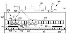
[0020]도 2는, 기판(10)을 코팅하기 위한 장치(200)의 실시예를 도시한다. 기판(10)은 기판 캐리어(12)에 부착된다. 기판 캐리어(12)는 기판 안내 시스템(270)에 의해 안내된다. 기판 안내 시스템(270)은, 예컨대, 기판 캐리어(12)를 아래로부터 지지하는 롤러들, 및 기판 캐리어를 위로부터 비접촉식으로(contactlessly) 안내하는 자석 안내 레일을 포함할 수 있다. 도 2에 도시된 기판 안내 시스템(270)은, 기판 캐리어(12) 및 기판(10)이 장치(200)의 진공 프로세스 챔버(202) 안으로 그리고 밖으로, 진공 프로세스 챔버(202)의 측벽들에 있는 대응하는 게이트들(도시되지 않음)을 통해 이송되는 것을 허용하도록 구성된다.[0020]Figure 2 shows an embodiment of an
[0021]장치(200)는 스퍼터 조립체(210)를 더 포함한다. 스퍼터 조립체(210)는, 제 1 회전 가능한 타겟(212) 및 제 1 마그네트론(214)을 구비한 제 1 스퍼터 소스(211)를 포함하고, 제 2 회전 가능한 타겟(222) 및 제 2 마그네트론(224)을 구비한 제 2 스퍼터 소스(221)를 포함한다. 스퍼터 조립체는 캐리지(carriage; 230) 상에 장착된다.[0021]The
[0022]장치(200)는 프로세스 가스 소스(260)를 포함한다. 프로세스 가스 소스(260)는, 아르곤, 제논, 크립톤, 네온, 산소, 질소, 수소, 및 수증기와 같은 가스들이 있는 하나 또는 그 초과의 탱크들을 포함할 수 있으며, 프로세스 가스를 형성하도록 이러한 가스들을 혼합하기 위한 가스 매니폴드(manifold)를 포함할 수 있다. 장치(200)는 가스 유입구 조립체(250)를 포함한다. 가스 유입구 조립체(250)는, 연결 라인(262)으로 프로세스 가스 소스(260)에 연결된 커넥터(252)를 포함한다. 가스 유입구 조립체(250)는, 제 1 연결 라인(253)에 의해 커넥터(252)에 연결된 제 1 가스 랜스(lance)(254), 제 2 연결 라인(255)에 의해 커넥터(252)에 연결된 제 2 가스 랜스(256), 및 제 3 연결 라인(257)에 의해 커넥터(252)에 연결된 제 3 가스 랜스(258)를 포함한다(도 3 참고). 제 1 스퍼터 소스(211)는 제 1 가스 랜스(254)와 제 2 가스 랜스(256) 사이에 배열되고, 제 2 스퍼터 소스(221)는 제 2 가스 랜스(256)와 제 3 가스 랜스(258) 사이에 배열된다. 가스 유입구 조립체(250)는 캐리지(230) 상에 장착된다.[0022]The
[0023]장치(200)는, 하나 또는 그 초과의 진공 펌프들을 포함할 수 있는 진공 펌프 시스템(265)을 포함한다. 도 2에서, 진공 펌프 시스템(265)을, 진공 프로세스 챔버(202)의 정면 벽에 배열된 가스 배출구(204)에 연결하는 하나의 진공 펌프 연결 라인(267)이 도시된다. 장치(200)는, 하나 초과의 진공 펌프 연결 라인 및 하나 초과의 가스 배출구, 예컨대, 가스 배출구들만큼 많은 진공 연결 라인들을 포함할 수 있다. 각각의 진공 펌프 연결 라인이 하나의 진공 펌프에 연결될 수 있거나 또는 여러 개의 진공 펌프 연결 라인들이 하나의 진공 펌프에 연결될 수 있다.[0023]
[0024]장치(200)는, 리니어 모터(linear motor)와 같은 구동부(245)를 구비한 구동 시스템(240)을 포함한다. 구동 시스템(240)은, 캐리지(230)가 상부에서 이동할 수 있는 트랙, 예컨대, 레일들을 포함할 수 있다. 캐리지(230), 그리고 따라서, 캐리지 상에 장착된, 스퍼터 조립체(210) 및 가스 유입구 조립체(250)는, 기판 안내 시스템(270)을 따른 그리고 기판 안내 시스템에 평행한 병진 운동을 달성하도록(effect) 구동 시스템(240)에 의해 구동된다. 제 1 쉴드(282) 및 제 2 쉴드(284)는 기판 안내 시스템(270)과 구동 시스템(240) 사이에 배열되며, 제 1 쉴드(282)와 제 2 쉴드(284) 사이에 갭이 존재하고, 갭은, 스퍼터 재료가 쉴드들 사이를 통과하여 기판(10)의 정면 표면 상으로 전달되는 것을 허용한다.[0024]The
[0025]스퍼터 재료가 제 1 회전 가능한 타겟(212)으로부터 그리고 제 2 회전 가능한 타겟(222)으로부터 스퍼터링되는 동안, 캐리지(230)는 적어도, 기판의 길이를 따라서, 그리고 특히 또한, 기판(10) 외부의 포지션들로 이동된다. 도 2에서, 스퍼터 조립체(210)는, 제 1 스퍼터 소스(211) 및 제 2 스퍼터 소스(221)가, 기판 프로세싱 영역의 외부의 쉴드(282)와 대면하는 제 1 포지션에 있는 것으로, 실선들을 이용하여 도시된다. 도 2에서의 파선 화살표는, 스퍼터 조립체(210) 및 프로세스 가스 유입구 조립체(250)를 구비한 캐리지(230)가 이동된 것을 나타내며, 캐리지(230)의 그리고 캐리지 상에 장착된 컴포넌트들의 제 2 포지션은 파선들에 의해 도시된다. 제 2 포지션에서, 제 1 스퍼터 소스(211) 및 제 2 스퍼터 소스(221)는 기판 프로세싱 영역에 있는 기판(10)과 대면한다.[0025]While the sputter material is sputtered from the first
[0026]장치(200)는 제어기(290)를 포함한다. 제어기(290)는, 캐리지(230)의 그리고 스퍼터 조립체(210)의 병진 운동, 그리고 캐리지 상에 장착된 가스 유입구 조립체(250)의 병진 운동을 제어할 수 있다. 특히, 제어기(290)는, 도 2에서 제어기(290)와 구동부(245)를 연결하는 선에 의해 표시된 바와 같이, 캐리지(230)의 그리고 캐리지 상에 장착된 컴포넌트들의 병진 운동을 달성하기 위해, 구동 시스템(240), 특히, 구동부(245)를 제어한다. 제어기(290)가 병진 운동을 제어하기 때문에, 제어기(290)는 캐리지(230)의, 제 1 회전 가능한 타겟(212)을 구비한 제 1 스퍼터 소스(211)의, 제 2 회전 가능한 타겟(222)을 구비한 제 2 스퍼터 소스(221)의, 그리고 가스 랜스들(254, 256, 및 258)의 현재 포지션들에 관한 정보를 보유한다. 제어기(290)는 또한, 가스 배출구(204)의 포지션에 대한 정보를 보유할 수 있다.[0026]
[0027]스퍼터 조립체(210)에 대한 그리고/또는 가스 유입구 조립체(250)에 대한 위치 정보에 기초하여, 제어기(290)는 프로세스 가스 공급부의 그리고 진공 프로세스 챔버로부터의 가스 진공배기의 특성들을 제어하는데, 즉, 제어기는 프로세스 가스 파라미터들을 제어한다.[0027]Based on the positional information for the
[0028]제어기(290)는, 도 2에서 프로세스 가스 소스(260)와 제어기(290)를 연결하는 선에 의해 표시된 바와 같이, 프로세스 가스 소스(260)를 제어할 수 있으며, 프로세스 가스의 조성은 제어기(290)에 의해 제어될 수 있다. 예컨대, 제어기(290)는, 현재의 프로세스 가스 조성을 형성하기 위해, 프로세스 가스 소스(260)에 포함된 상이한 가스들이 어떤 비율로 혼합되는지를 제어할 수 있다. 프로세스 가스는, 연결 라인(262)에 의해 프로세스 가스 소스(260)로부터 커넥터(252)로 전달된다. 제어기(290)는, 예컨대, 연결 라인(262)을 통하는 유동을 조절함으로써, 스퍼터 조립체(210)로의 프로세스 가스의 전체 유동을 제어할 수 있다. 조절은, 연결 라인(262)의 또는 커넥터(252)의 밸브에 의해, 또는 유사한 방식으로 이루어질 수 있다. 제어기(290)는 프로세스 가스의 분배를 더 제어할 수 있다. 이는, 제어기(290)가, 도 2에 도시된 가스 랜스들(254, 256, 및 258)과 같은 개별 가스 유입구들을 통한, 프로세스 가스의 부분적인 유동들을 제어할 수 있다는 것을 의미한다. 제어기는, 예컨대, 연결 라인들(253, 255, 257)의 개별 밸브들(도 3 참고)에 의해, 또는 커넥터(252)의 분배 시스템에 의해, 부분적인 유동들을 제어할 수 있다.[0028]The
[0029]또한, 제어기는, 도 2에서 제어기(290)와 진공 펌핑 시스템(265)을 연결하는 선에 의해 표시된 바와 같이, 펌핑 시스템(265)을 제어할 수 있다. 제어기는, 진공 프로세스 챔버(202) 밖으로 펌핑되는 가스의 전체 유동을 제어할 수 있으며, 하나 초과의 가스 배출구들이 존재하는 경우에, 각각의 가스 배출구 밖으로 펌핑되는 부분적인 유동들의 분배를 제어할 수 있다. 제어기는, 진공 펌핑 시스템(265)의 진공 펌프(들)를 직접 제어할 수 있거나, 또는, 예컨대, 진공 펌프 연결 라인(267)에 또는 가스 배출구(204)와 같은 가스 배출구들에 배열될 수 있는 조절 밸브들을 제어할 수 있다.[0029]The controller may also control the
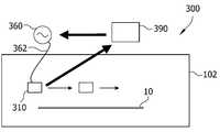
[0030]도 3은, 스퍼터 프로세스 동안 제어기(290)에 의해 실시되는 제어의 예를 개략적으로 예시한다. 스퍼터링이 수행되는 동안, 도 3에서 스퍼터 조립체(210), 특히, 제 1 스퍼터 소스(211) 및 제 2 스퍼터 소스(221)가 왼쪽으로부터 오른쪽으로 이동할 때, 스퍼터 조립체(210)는 프로세싱 구역(P) 외부의 구역으로부터 프로세싱 구역(P) 내로 이동할 것이고, 여기서 스퍼터 조립체(210)는 기판(10)과 대면하며, 그리고 다시 프로세싱 구역(P) 외부의 구역으로 이동할 것이고, 여기서 스퍼터 조립체(210)는 진공 프로세스 챔버의 다른 컴포넌트들, 예컨대, 도 3에 도시된 쉴드들(282 및 284), 또는 챔버 벽들, 등과 대면한다. 도 2 및 3에서, 프로세싱 구역(P)은 쉴드(282)와 쉴드(284) 사이의 갭에 포함된다.[0030]Figure 3 schematically illustrates an example of the control implemented by the
[0031]도 3에 도시된 예에서, 제어기(290)는, 연결 라인(262)을 통해 가스 유입구 조립체(250)로 전달되는 프로세스 가스의 전체 유동(F)을, 스퍼터 조립체(210)의 포지션(x)에 기초하여 맞춤조절하고, 프로세스 가스의 분배, 즉, 연결 라인들(253, 255, 및 257)을 통한, 개별 가스 랜스들(254, 256, 및 258)로의 부분적인 유동들을, 스퍼터 소스들의 또는 가스 랜스들의 포지션에 따라 맞춤조절한다. 예컨대, 전체 유동(F)은, 스퍼터 소스들(211, 221)이 기판과 대면하지 않는 제 1 외부 구역(E1)에서 더 높을 수 있고, 스퍼터 조립체(210)의 그리고 가스 유입구 조립체(250)의 컴포넌트들이 프로세싱 구역(P) 내에 진입하기 시작하는 제 1 전이 구역(T1)에서 감소할 수 있으며, 이러한 컴포넌트들 모두가 프로세싱 구역(P)에 있고 기판(10)과 대면하는 중앙 구역(C)에서(도 3에서 파선들로 도시됨) 일정하게 유지될 수 있고, 그리고, 스퍼터 조립체(210)의 그리고 가스 유입구 조립체(250)의 컴포넌트들이 프로세싱 구역(P)을 빠져나가기 시작하는 제 2 전이 구역(T2)에서 증가할 수 있으며, 그리고, 스퍼터 소스들(211, 221)이 기판과 대면하지 않는 제 2 외부 구역(E2)에서는, 다시 제 1 외부 구역(E1)에서와 같은 값에 있을 수 있다.[0031]3, the
[0032]제 1 전이 구역(T1)에서 그리고 제 2 전이 구역(T2)에서, 제어기는 프로세스 가스의 분배를 맞춤조절할 수 있다. 예컨대, 제어기는, 도 3에서 실선들로 도시된, 캐리지(230) 및 스퍼터 조립체(210)의 포지션에서, 가스 유입구 조립체(250)가, 연결 라인(253)을 통해 가스 랜스(254)에 그리고 연결 라인(255)을 통해 가스 랜스(256)에 전달하는 것보다, 연결 라인(257)을 통해 가스 랜스(258)에 더 적은 프로세스 가스를 전달하도록 제어할 수 있다. 스퍼터 조립체(210) 및 가스 유입구 조립체(250)가 상부에 장착된 캐리지(230)가 도 3에서 오른쪽으로 더 이동할 때, 그러면 제어기(290)는, 일단 가스 랜스(256)가 프로세싱 구역(P) 내에 진입하면, 연결 라인(255)을 통하는 부분적인 유동을 감소시킴으로써 전이 구역(T1)에서 프로세스 가스의 분배를 맞춤조절할 수 있고, 그런 다음에, 가스 랜스(254)가 프로세싱 구역(P)에 진입할 때, 연결 라인(253)을 통하는 부분적인 유동을 감소시킬 수 있다. 전이 구역(T2)에서, 그에 따라서 부분적인 유동들은 동일한 순서로 증가될 수 있다.[0032]In the first transition zone T1 and in the second transition zone T2, the controller can customize the distribution of the process gas. For example, in the position of the
[0033]제어기(290)는, 도 3에 예시적으로 도시된 바와 같은 가스 파라미터 프로파일을 저장하는 메모리 섹션을 포함할 수 있다. 캐리지(230)가 진공 프로세스 챔버를 통해 병진 운동으로 이동하는 동안, 그리고 스퍼터 조립체(210)가 스퍼터링하는 동안, 제어기는, 가스 파라미터 프로파일로부터 취해진 값들에 의해 프로세스 가스 파라미터들을 맞춤조절할 수 있다.[0033]The
[0034]도 3에 예시된 바와 같이, 제어기(290)에 의해 실시되는 제어는 오직 예시적인 것이며, 제한으로서 이해되어서는 안된다. 특히, 가스 파라미터 프로파일은 더 복잡할 수 있고, 가스 유입구 조립체의 그리고/또는 스퍼터 조립체의 컴포넌트들의 현재 포지션들에 기초한, 전체 가스 유동, 프로세스 가스의 분배, 및/또는 프로세스 가스의 조성에 대한 제어 정보를 포함할 수 있다. 게다가, 제어는, 챔버 기하형상, 예컨대, 하나 또는 그 초과의 진공 펌프들이 진공 프로세스 챔버의 내부 용적을 진공배기하는 진공 배출구(들)의 포지션(들) 및/또는 진공 프로세스 챔버의 챔버 벽들의 또는 다른 컴포넌트들의 형상 및 부근의 추가적인 양태들에 따를 수 있다. 가능하게는 하나 또는 그 초과의 가스 파라미터 프로파일들에 저장된 대응하는 제어 정보는, 제어기가, 스퍼터 프로세스의 작동 지점을 스퍼터 프로세스 내내 일정하게 유지할 수 있게 한다. 제어기는 부가적으로, 스퍼터 프로세스 이전에 일어나는 스퍼터-전(pre-sputter) 프로세스에서 프로세스 가스 파라미터들 또는 다른 파라미터들을 변화시킬 수 있다. 스퍼터-전 프로세스의 제어는 포지션과 무관할 수 있으며, 예비-스퍼터링(pre-sputtering)은, 외부 구역(E1)에서와 같이, 고정된 포지션에서 수행될 수 있다.[0034]As illustrated in Figure 3, the control implemented by the
[0035]스퍼터 프로세스의 작업 지점을 일정하게 유지하는 것은, 기판 상에 스퍼터링되는 코팅의 균일성을 증가시키는 역할을 한다. 스퍼터 소스(들)를 이동시키는 것과, 프로세스 가스가 진공 프로세스 챔버 내에 얼마나 도입되는지에 대한 제어의 조합은, 매우 균일한 코팅 결과로 이어질 것으로 여겨진다. 또한, 스퍼터 소스(들)의 운동은, 진공 프로세스 챔버에서 스퍼터 소스들의 정적(static) 어레인지먼트와 비교하여, 더 적은 개수의 스퍼터 소스들을 사용하는 것을 허용한다. 이는, 기판 상에 스퍼터링되는 타겟 재료가 비싼 경우에 특히 유리할 수 있다. 예컨대, 산소 및 질소와 같은 반응성 가스들을 사용하는 반응성 스퍼터링의 경우에, 안정적인 작동 지점은, 성장하는 층의 화학량론(stoichiometry)에 긍정적인 영향을 미친다.[0035]Keeping the working point of the sputter process steady serves to increase the uniformity of the coating sputtered on the substrate. It is believed that the combination of moving the sputter source (s) and control over how far the process gas is introduced into the vacuum process chamber will result in a very uniform coating result. In addition, movement of the sputter source (s) allows the use of fewer numbers of sputter sources, as compared to the static arrangement of the sputter sources in the vacuum process chamber. This may be particularly advantageous if the target material sputtered on the substrate is expensive. For example, in the case of reactive sputtering using reactive gases such as oxygen and nitrogen, a stable operating point has a positive effect on the stoichiometry of the growing layer.
[0036]본 개시물의 실시예들은, 기판 상에서의 층들의 형성을 용이하게 하며, 층들은 높은 품질을 갖는다. 특히, 기판 상에 증착된 층의 두께는 전체 기판에 걸쳐서 매우 균일할 수 있다. 게다가, 층의 높은 균질성이 (예컨대, 성장 결정의 구조, 비저항, 및/또는 층 응력과 같은 특성들의 측면에서) 용이해진다. 예컨대, TFT들의 생산에서, 신호 지연은 층의 두께에 따르고, 이에 의해 두께 불-균일성은, 살짝 상이한 시간들에 에너자이징되는 픽셀들을 초래할 수 있기 때문에, 본 개시물의 실시예들은, TFT들의 생산에서 금속화된 층들을 형성하는 경우에(예컨대, TFT-LCD 디스플레이들의 제조의 경우에) 유리할 수 있다. 게다가, 층 두께의 균일성은, 형성된 층의 상이한 포지션들에서 동일한 결과들을 달성하는 것을 용이하게 하기 때문에, 본 개시물의 실시예들은, 후속하여 에칭되는 층들을 형성하는 경우에 유리할 수 있다.[0036]Embodiments of the disclosure facilitate the formation of layers on a substrate, and the layers have a high quality. In particular, the thickness of the layer deposited on the substrate can be very uniform across the entire substrate. In addition, the high homogeneity of the layer (e. G. In terms of properties such as growth crystal structure, resistivity, and / or layer stress) is facilitated. For example, in the production of TFTs, the signal delay depends on the thickness of the layer, and because the thickness non-uniformity can result in pixels being energized at slightly different times, (E.g., in the case of the manufacture of TFT-LCD displays). In addition, embodiments of the present disclosure may be advantageous in the case of forming subsequently etched layers, since uniformity of the layer thickness facilitates achieving the same results at different positions of the formed layer.
[0037]도 4는, 기판(10)을 코팅하기 위한 장치(300)의 추가적인 실시예를 도시한다. 장치(300)는, 적어도 하나의 스퍼터 소스를 포함하는 스퍼터 조립체(310)를 포함한다. 장치(300) 및/또는 스퍼터 조립체(310)는, 도 1, 2, 및 3과 관련하여 본원에서 설명되는 장치 및 스퍼터 조립체와 동일하거나 유사한 특성들을 가질 수 있다. 장치(300)는, 도 1, 2, 및 3과 관련하여 설명된 제어기의 특성들 중 임의의 특성을 가질 수 있는 제어기(390)를 포함할 수 있다. 제어기(390)는, 전기 연결 라인(362)을 통해 스퍼터 조립체(310)에 연결된 전력 소스(360)를 제어하도록 구성된다. 특히, 제어기는, 스퍼터 조립체(310)의 적어도 하나의 스퍼터 소스의 또는 스퍼터 조립체(310)의 현재 포지션에 따라, 전력 소스(360)에 의해 적어도 하나의 스퍼터 소스에 인가되는 전력을 제어하도록 구성된다. 여기에서, 본원에서 설명된 바와 같이 프로세스 가스 파라미터들을 제어하는 것에 부가하여, 전력이 제어기(390)에 의해 제어될 수 있다.[0037]Figure 4 illustrates a further embodiment of an
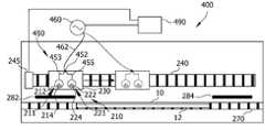
[0038]도 5에 도시된 실시예에서, 기판(10)을 코팅하기 위한 장치(400)는, 도 2 및 3과 관련하여 설명된 제어기의 모든 기능들을 수행할 수 있는 제어기(490)를 포함한다. 부가적으로, 제어기는 전력 소스(460)를 제어한다. 전력 소스(460)는, 전기 연결 라인(462)에 의해, 전력 분배 시스템(450)에, 특히 전력 커넥터(452)에 연결된다. 전력 커넥터(452)는 전기 연결 라인(453)을 통해 제 1 스퍼터 소스(211)에 연결되고, 전기 연결 라인(455)을 통해 제 2 스퍼터 소스(221)에 연결된다. 제어기(490)는, 제 1 스퍼터 소스(211)의 그리고 제 2 스퍼터 소스(221)의 현재 포지션들에 기초하여, 제 1 스퍼터 소스(211)에 인가되는 전력을 제어하고, 제 2 스퍼터 소스(221)에 인가되는 전력을 제어한다. 예컨대, 제어기(490)는, 도 5에서 파선들로 도시된 포지션들에서보다, 도 5에서 실선들로 도시된, 제 1 스퍼터 소스(211)의 그리고 제 2 스퍼터 소스(221)의 포지션들 및 캐리지(230)의 포지션에서 스퍼터 소스들에 인가되는 전력이 더 높도록 제어할 수 있다. 제어기는, 스퍼터 소스들에 인가되는 전력을 제어하기 위해, 메모리 섹션에 저장된 전력 프로파일을 포함할 수 있고, 스퍼터 소스들의 또는 스퍼터 조립체(210)의 포지션에 따른 전력 프로파일을 액세싱할 수 있다.[0038]In the embodiment shown in FIG. 5, the
[0039]이러한 방식으로, 프로세스 가스 파라미터들 및 전력 파라미터들을 제어함으로써, 스퍼터 프로세스의 동작 지점이 안정화될 수 있고 더욱 더 양호하게 일정하게 유지될 수 있으며, 기판의 정면 표면 상에 스퍼터링되는 층의 증가된 균일성으로 이어진다.[0039]In this way, by controlling the process gas parameters and power parameters, the operating point of the sputter process can be stabilized and maintained even better, and the increased uniformity of the layer sputtered on the front surface of the substrate .
[0040]본원에서 설명되는 실시예들 중 임의의 실시예와 결합될 수 있는 실시예에 따르면, 기판을 코팅하기 위한 장치가 제공된다. 기판은 TFT 기판 또는 웨이퍼일 수 있다. 기판은 유리 기판, 폴리머 기판, 또는 반도체 기판일 수 있다. 기판은 더 대면적인(larger area) 기판, 예컨대, 6세대(GEN), 7세대, 7.5세대, 8세대, 8.5세대, 10세대, 또는 더 높은 세대의 대면적 기판일 수 있다. 기판의 치수들은, 예컨대, 1100mm x 1250mm와 동일하거나 더 클 수 있거나, 1500mm x 1800mm와 동일하거나 더 클 수 있거나, 2160mm x 2460mm와 동일하거나 더 클 수 있거나, 2200mm x 2500mm와 동일하거나 더 클 수 있거나, 또는 심지어 2880mm x 3130mm와 동일하거나 더 클 수 있다. 장치는, 그러한 기판들을 코팅하기 위한, 특히, 스퍼터 재료의 하나 또는 그 초과의 층들을 그러한 기판들 상에 스퍼터링하기 위한 코팅 설비일 수 있다. 장치는 하나 또는 여러 개의 프로세스 챔버들, 하나 또는 그 초과의 이송 챔버들, 하나 또는 그 초과의 로드 록 챔버들, 하나 또는 그 초과의 스윙 모듈들(swing modules), 및/또는 하나 또는 그 초과의 회전 모듈들을 포함할 수 있다. 장치의 챔버 및 모듈들은, 본원에서 설명되는 기판들을 수용하도록 크기가 정해질 수 있다. 여기에서, 기판들은 장치를 통해 직립 형태(upright format)로 이송될 수 있는데, 이는, 더 짧은 측이, 장치를 통한 기판의 이송 방향에 대해 평행하다는 것을 의미한다. 이러한 경우에, 장치의 풋프린트(footprint)는, 기판들이, 더 긴 측이 이송 방향에 대해 평행하다는 것을 의미하는 가로 형태(landscape format)로 이송되는 다른 선택 사항보다 더 작을 수 있다.[0040]According to embodiments that may be combined with any of the embodiments described herein, an apparatus for coating a substrate is provided. The substrate may be a TFT substrate or a wafer. The substrate may be a glass substrate, a polymer substrate, or a semiconductor substrate. The substrate may be a larger area substrate, such as a sixth generation (GEN), seventh, seventh, eighth, ninth, tenth, or higher generation large area substrate. The dimensions of the substrate may be equal to or greater than, for example, 1100 mm x 1250 mm, equal to or greater than 1500 mm x 1800 mm, equal to or greater than 2160 mm x 2460 mm, equal to or greater than 2200 mm x 2500 mm , Or even equal to or larger than 2880 mm x 3130 mm. The apparatus may be a coating facility for coating such substrates, in particular for sputtering one or more layers of sputter material onto such substrates. The apparatus may comprise one or more process chambers, one or more transfer chambers, one or more load lock chambers, one or more swing modules, and / or one or more Rotation modules. The chamber and modules of the apparatus may be sized to accommodate the substrates described herein. Here, the substrates may be transported through the device in an upright format, which means that the shorter side is parallel to the transport direction of the substrate through the device. In such a case, the footprint of the device may be smaller than the other choices conveyed in landscape format, meaning that the longer sides are parallel to the transport direction.
[0041]장치는 진공 프로세스 챔버를 포함한다. 진공 프로세스 챔버는, 진공 프로세스 챔버를 진공배기하기 위한 진공 펌프 시스템에 연결될 수 있다. 진공 프로세스 챔버 및 진공 펌프 시스템은, 진공 프로세스 챔버에 진공 환경을 제공하도록 구성될 수 있다. 본 출원 내에서 "진공"이라는 용어는, 10-2mbar 아래의 압력(예컨대, 프로세스 가스가 진공 프로세스 챔버 내에서 유동할 때일 수 있는 경우와 같이, 대략적으로 10-2mbar(그러나 이에 제한되지 않음))을 지칭하거나, 또는 더 구체적으로, 10-3mbar 아래의 압력(예컨대, 프로세스 가스가 진공 프로세스 챔버 내에서 유동하지 않을 때일 수 있는 경우와 같이, 대략적으로 10-5mbar(그러나 이에 제한되지 않음))을 지칭한다. 진공 프로세스 챔버는 진공 프로세스 챔버 벽들을 포함할 수 있다. 진공 프로세스 챔버는, 기판을 진공 프로세스 챔버 내에 도입하기 위한 그리고/또는 기판을 진공 프로세스 챔버 밖으로 이송하기 위한 게이트 또는 게이트들을 포함할 수 있다. 게이트(들)는 진공 프로세스 챔버 벽들 중 적어도 하나에, 예컨대, 하나 또는 그 초과의 측벽들에 형성될 수 있다. 게이트(들)는, 이웃하는 챔버 또는 이웃하는 모듈에 진공을 기밀(tightly) 연결하기 위한 게이트 밸브 또는 게이트 밸브들을 포함할 수 있다.[0041] The apparatus includes a vacuum process chamber. The vacuum process chamber may be connected to a vacuum pump system for evacuating the vacuum process chamber. The vacuum process chamber and vacuum pump system may be configured to provide a vacuum environment in the vacuum process chamber. The term "vacuum" within this application, 10-2 mbar pressure under (e. G., As in the case that the process gas can ttaeil to flow in the vacuum process chamber, is not limited to approximately 10-2 mbar (but this ), Or, more specifically, at a pressure below 10-3 mbar (e.g., about 10-5 mbar (but not limited to, such as when the process gas may not flow in the vacuum process chamber )). The vacuum process chamber may include vacuum process chamber walls. The vacuum process chamber may include gates or gates for introducing the substrate into the vacuum process chamber and / or for transferring the substrate out of the vacuum process chamber. The gate (s) may be formed in at least one of the vacuum process chamber walls, e.g., on one or more sidewalls. The gate (s) may comprise gate or gate valves for tightly connecting the vacuum to a neighboring chamber or neighboring module.
[0042]진공 프로세스 챔버는 스퍼터 조립체를 포함한다. 스퍼터 조립체는 스퍼터 소스를 포함한다. 스퍼터 소스는 타겟, 특히, 회전 가능한 타겟 또는 평면 타겟을 포함할 수 있다. 타겟은, Al, Mo, Ti, Cu, ITO, IZO, IGZO, W, Si, Nb 또는 이들의 합금들 또는 조성물들(compositions)을 포함할 수 있거나 또는 이들로 구성될 수 있다. 스퍼터 소스는 마그네트론 조립체, 특히, 스퍼터 소스의 회전 가능한 타겟 내부에 배열된 마그네트론 조립체를 포함할 수 있다. 마그네트론 조립체는 고정된 배향을 가질 수 있거나, 또는 진동 운동(oscillating movement)을 수행하도록 구성될 수 있다.[0042]The vacuum process chamber includes a sputter assembly. The sputter assembly includes a sputter source. The sputter source may comprise a target, particularly a rotatable target or a planar target. The target may comprise or consist of Al, Mo, Ti, Cu, ITO, IZO, IGZO, W, Si, Nb or alloys or compositions thereof. The sputter source may comprise a magnetron assembly, particularly a magnetron assembly arranged within the rotatable target of the sputter source. The magnetron assembly may have a fixed orientation or may be configured to perform an oscillating movement.
[0043] 스퍼터 소스는 스퍼터 조립체의 제 1 스퍼터 소스일 수 있고, 스퍼터 조립체는 N개의 추가적인 스퍼터 소스들을 포함할 수 있으며, N은 1 내지 20 범위, 예컨대, 1 내지 10 범위에 있을 수 있다. 예컨대, 스퍼터 조립체는 1, 2, 3, 4, 5, 6, 7, 8, 9, 10 또는 그 초과의 추가적인 스퍼터 소스들을 포함할 수 있다. 추가적인 스퍼터 소스(들), 예컨대, 제 2, 제 3, 제 4 등의 스퍼터 소스들은 제 1 스퍼터 소스와 동일한 유형일 수 있다. 스퍼터 소스들의 전체 개수는 N+1일 수 있으며, 스퍼터 소스들은 직선(line)을 따라서 또는 곡선(bow)으로 배열될 수 있다. 스퍼터 소스들은, 스퍼터 소스들 사이에 규칙적인 공간들이 있게 배열될 수 있거나, 또는 스퍼터 소스들 사이에 변하는 공간들이 있게 배열될 수 있다. 스퍼터 소스들은 스퍼터 소스 어레이(array)를 형성할 수 있다.[0043] The sputter source may be the first sputter source of the sputter assembly, and the sputter assembly may include N additional sputter sources, where N may range from 1 to 20, for example, from 1 to 10. [ For example, the sputter assembly may comprise 1, 2, 3, 4, 5, 6, 7, 8, 9, 10 or more additional sputter sources. Additional sputter source (s), e.g., second, third, fourth, etc., sputter sources may be of the same type as the first sputter source. The total number of sputter sources may be N + 1, and the sputter sources may be arranged along a line or with a bow. The sputter sources may be arranged with regular spaces between the sputter sources, or they may be arranged with varying spaces between the sputter sources. The sputter sources may form a sputter source array.
[0044]진공 프로세스 챔버는 가스 유입구 조립체를 포함한다. 가스 유입구 조립체는, 하나 또는 그 초과의 프로세스 가스 소스들에 연결하기 위해 적어도 하나의 커넥터를 포함한다. 장치는 하나 또는 그 초과의 프로세스 가스 소스들을 포함할 수 있고, 그리고/또는 하나 또는 그 초과의 프로세스 가스 소스들을 가스 유입구 조립체의 적어도 하나의 커넥터에 연결하기 위한 하나 또는 그 초과의 연결 라인들, 예컨대, 하나 또는 그 초과의 파이프들 또는 튜브들을 포함할 수 있다. 프로세스 가스 또는 프로세스 가스들, 예컨대, 반응성 스퍼터링을 위한 프로세스 가스(들) 또는 불활성 스퍼터링을 위한 프로세스 가스(들)는 하나 또는 그 초과의 프로세스 가스 소스들에 포함될 수 있다. 반응성 스퍼터링을 위한 프로세스 가스의 예들은, O2, N2, H2, H2O 또는 이들의 혼합물들이다. 불활성 스퍼터링을 위한 프로세스 가스의 예들은, Ar, Xe, Kr, Ne 또는 이들의 혼합물들이다.[0044] The vacuum process chamber includes a gas inlet assembly. The gas inlet assembly includes at least one connector for connecting to one or more process gas sources. The apparatus may include one or more process gas sources and / or one or more connection lines for connecting one or more process gas sources to at least one connector of the gas inlet assembly, for example, , One or more pipes or tubes. Process gas or process gases, such as process gas (s) for reactive sputtering or process gas (s) for inert sputtering, may be included in one or more process gas sources. Examples of process gases for reactive sputtering are O2 , N2 , H2 , H2 O, or mixtures thereof. Examples of process gases for inert sputtering are Ar, Xe, Kr, Ne or mixtures thereof.
[0045]가스 유입구 조립체는, 프로세스 가스를 진공 프로세스 챔버 내에 도입하기 위한 M개의 가스 유입구들을 포함할 수 있으며, 여기서 M은, 1 내지 30 범위, 특히, 2 내지 20 범위에 있다. 가스 유입구들의 개수(M)는, M=N'+1이라는 관계(여기서 N'는 1 이거나, N+1이고 N은 상기 서술된 바와 같음)에 의해, 또는 M=N'-1이라는 관계(여기서 N'는 N+1이고 N은 상기 서술된 바와 같음)에 의해 스퍼터 소스들의 개수(N')와 관련될 수 있다. 가스 유입구들은, 가스 유입구들의 모든 쌍으로부터 진공 프로세스 챔버 내로 빠져나가는 프로세스 가스 유동들 사이에 하나의 스퍼터 소스가 있도록 배열될 수 있다. 가스 유입구들은, 각각의 가스 유입구에 대해서, 특정 가스 유입구로부터 진공 프로세스 챔버 내로 빠져나가는 프로세스 가스 유동이, 스퍼터 소스들의 상이한 쌍 사이로 지향되도록 배열될 수 있다. 가스 유입구들은, 가스 유입구들의 모든 쌍 사이마다 하나의 스퍼터 소스가 있도록 배열될 수 있다. 가스 유입구들은, 스퍼터 소스들의 모든 쌍 사이마다 하나의 가스 유입구가 있도록 배열될 수 있다. 가스 유입구들은 가스 랜스들일 수 있다. 가스 유입구들은, 예컨대, 파이프들 또는 튜브들의 시스템에 의해, 적어도 하나의 커넥터와 유체 연결(fluid connection)된다.[0045]The gas inlet assembly may include M gas inlets for introducing the process gas into the vacuum process chamber, where M ranges from 1 to 30, in particular from 2 to 20. The number M of gas inlets is determined by the relationship M = N '+ 1 where N' is 1 or N + 1 and N is as described above, or the relationship M = N'-1 Where N 'is N + 1 and N is as described above). The gas inlets may be arranged such that there is one sputter source between the process gas flows exiting the vacuum process chamber from all pairs of gas inlets. The gas inlets may be arranged such that, for each gas inlet, the process gas flow exiting the particular gas inlet into the vacuum process chamber is directed between different pairs of sputter sources. The gas inlets may be arranged such that there is one sputter source between every pair of gas inlets. The gas inlets may be arranged such that there is one gas inlet between every pair of sputter sources. The gas inlets may be gas lances. The gas inlets are in fluid connection with at least one connector, e.g., by a system of pipes or tubes.
[0046]진공 프로세스 챔버는 하나 또는 그 초과의 가스 배출구들, 예컨대, L개의 가스 배출구들을 포함할 수 있고, 여기서 L은 1 내지 10 범위에 있다. 하나 또는 그 초과의 가스 배출구들은, 하나 또는 그 초과의 진공 펌프들을 포함하는 진공 펌프 시스템과의 연결을 위해 구성될 수 있다. 하나 또는 그 초과의 가스 배출구들은 챔버 벽에 또는 챔버 벽들에, 예컨대, 진공 프로세스 챔버의 정면 벽 또는 후면 벽에 배열될 수 있다. 장치는 진공 펌프 시스템을 포함할 수 있고, 특히, 하나 또는 그 초과의 가스 배출구들에 연결된 하나 또는 그 초과의 진공 펌프들을 포함할 수 있다.[0046]The vacuum process chamber may include one or more gas outlets, e.g., L gas outlets, where L is in the range of 1 to 10. One or more gas outlets may be configured for connection with a vacuum pump system comprising one or more vacuum pumps. One or more gas outlets may be arranged in the chamber wall or in the chamber walls, for example in the front wall or rear wall of the vacuum process chamber. The apparatus may comprise a vacuum pump system, and in particular may include one or more vacuum pumps connected to one or more gas outlets.
[0047]본원에서 설명되는 실시예들에 따르면, 스퍼터 조립체는, 진공 프로세스 챔버에서 이동 가능하다. 특히, 스퍼터 조립체는 진공 챔버에 대해, 특히, 진공 프로세스 챔버 벽(들)에 대해 이동 가능할 수 있다. 스퍼터 조립체는, 기판이 진공 프로세스 챔버에 로딩되는 경우, 기판에 대해 이동 가능할 수 있다. 스퍼터 조립체는 병진 운동으로 이동 가능할 수 있다. 병진 운동은, 코팅되는 기판의 기판 표면에 대해 평행할 수 있다. 병진 운동은 하나 또는 그 초과의 챔버 벽들에 대해 평행, 예컨대, 진공 프로세스 챔버의 정면 벽 및/또는 후면 벽에 대해 평행할 수 있다. 병진 운동은 연속 운동, 특히 균일한 운동, 즉, 적어도, 본원에서 설명되는 바와 같은 프로세싱 구역에서 일정한 속도를 갖는 운동일 수 있다.[0047]According to embodiments described herein, the sputter assembly is movable in a vacuum process chamber. In particular, the sputter assembly can be movable relative to the vacuum chamber, particularly with respect to the vacuum process chamber wall (s). The sputter assembly may be movable relative to the substrate when the substrate is loaded into the vacuum process chamber. The sputter assembly may be movable in translational motion. The translational motion may be parallel to the substrate surface of the substrate being coated. The translational motion may be parallel to one or more chamber walls, e.g., parallel to the front and / or back wall of the vacuum process chamber. The translational motion may be a continuous motion, in particular a uniform motion, i. E. At least a motion with a constant velocity in the processing zone as described herein.
[0048]장치는, 스퍼터 조립체에 커플링된 구동 시스템을 포함할 수 있고, 구동 시스템은, 스퍼터 조립체의 병진 운동을 달성하도록 구성된다. 스퍼터 조립체, 그리고 특히, 스퍼터 조립체의 스퍼터 소스(들)는 캐리지 상에 장착될 수 있다. 캐리지는 병진 운동으로 이동 가능할 수 있다. 장치는, 캐리지를 지지하고 이동시키기 위한 트랙, 예컨대, 레일 시스템을 포함할 수 있다. 장치는, 스퍼터 조립체의 캐리지에 커플링된 구동 시스템을 포함할 수 있고, 구동 시스템은, 캐리지의 병진 운동을 달성하도록 구성된다.[0048]The apparatus may include a drive system coupled to the sputter assembly, wherein the drive system is configured to effect translational motion of the sputter assembly. The sputter assembly, and in particular the sputter source (s) of the sputter assembly, can be mounted on a carriage. The carriage may be movable in translational motion. The apparatus may include a track, e.g., a rail system, for supporting and moving the carriage. The apparatus may include a drive system coupled to a carriage of the sputter assembly, wherein the drive system is configured to effect translational motion of the carriage.
[0049] 가스 유입구 조립체는 스퍼터 조립체와 함께 이동 가능할 수 있다. 특히, 가스 유입구 조립체 및 스퍼터 조립체는 캐리지 상에 함께 장착될 수 있다. 적어도 하나의 커넥터를 하나 또는 그 초과의 프로세스 가스 소스들에 연결하기 위한, 파이프들 또는 튜브들과 같은 연결 라인들은 가요성(flexible)일 수 있거나, 또는 적어도 연결 라인들의 일부에서 가요성일 수 있다. 따라서, 적어도 하나의 커넥터를 하나 또는 그 초과의 프로세스 가스 소스들에 연결하기 위한 연결 라인들은, 가스 유입구 조립체의 이동에 대해 굽힘(bending)으로써 반응할 수 있다. 대안적으로, 가스 유입구 조립체, 그리고 특히, 가스 유입구 조립체의 가스 유입구 또는 가스 유입구들은 진공 프로세스 챔버에 고정적으로 배열될 수 있다.[0049] The gas inlet assembly may be movable with the sputter assembly. In particular, the gas inlet assembly and the sputter assembly may be mounted together on the carriage. Connection lines, such as pipes or tubes, for connecting at least one connector to one or more process gas sources may be flexible, or may be flexible at least in some of the connection lines. Thus, the connection lines for connecting at least one connector to one or more process gas sources may react by bending against movement of the gas inlet assembly. Alternatively, the gas inlet assembly, and particularly the gas inlet or gas inlet of the gas inlet assembly, may be fixedly arranged in the vacuum process chamber.
[0050] 장치, 특히 진공 프로세스 챔버는, 진공 프로세스 챔버에 배열된 기판 안내 시스템을 포함할 수 있다. 기판 안내 시스템은, 코팅 동안 기판을 지지하기 위해 배열되고 배향될 수 있다. 기판 안내 시스템은, 예컨대, 진공 프로세스 챔버의 측벽들에 있는 하나 또는 그 초과의 게이트들을 통해, 기판을 진공 프로세스 챔버 내로 그리고 밖으로 이동시키기 위해 배열될 수 있다. 기판 안내 시스템은, 기판을 홀딩하는 기판 캐리어 또는 기판을 지지하기 위한 트랙, 예컨대, 롤러들의 조립체, 및/또는 기판/기판 캐리어를 안내하기 위한 트랙, 예컨대, 기판 캐리어와 상호 작용하는 자석 레일을 포함할 수 있다. 스퍼터 조립체, 특히, 캐리지는, 존재하는 경우에, 기판 안내 시스템을 따라 이동 가능할 수 있다. 가스 유입구 조립체가 진공 프로세스 챔버에 고정적으로 배열되는 경우에, 스퍼터 조립체, 그리고 특히 캐리지는, 가스 유입구 조립체와 기판 안내 시스템 사이에 배열될 수 있다.[0050] The apparatus, particularly the vacuum process chamber, may include a substrate guide system arranged in a vacuum process chamber. The substrate guide system can be arranged and oriented to support the substrate during coating. The substrate guide system may be arranged to move the substrate into and out of the vacuum process chamber, for example, through one or more gates in the sidewalls of the vacuum process chamber. The substrate guide system includes a substrate carrier for holding the substrate or a track for supporting the substrate, e.g., an assembly of rollers, and / or a track for guiding the substrate / substrate carrier, e.g., a magnetic rail that interacts with the substrate carrier can do. The sputter assembly, and in particular the carriage, if present, can be movable along the substrate guiding system. When the gas inlet assembly is fixedly arranged in the vacuum process chamber, the sputter assembly, and in particular the carriage, can be arranged between the gas inlet assembly and the substrate guide system.
[0051]진공 프로세스 챔버는 프로세싱 구역을 포함할 수 있다. 프로세싱 구역은 적어도, 진공 프로세스 챔버에서 기판의 이송 방향에 대해 평행한, 기판의 치수만큼 넓을(wide) 수 있으며, 적어도, 진공 프로세스 챔버에서 기판의 이송 방향에 대해 수직인, 기판의 치수만큼 높을(high) 수 있다. 진공 프로세스 챔버는 쉴드들을 포함할 수 있다. 프로세싱 구역은, 쉴드들 사이의 갭에 의해 정의될 수 있거나, 그러한 갭에 포함될 수 있다. 쉴드들은, 코팅 동안에 기판 또는 기판 캐리어를 쉴딩하기 위해, 기판 안내 시스템에 배열될 수 있다. 진공 프로세스 챔버는 프로세싱 구역 외부의 적어도 하나의 비(non)-프로세싱 구역, 예컨대, 프로세싱 구역의 각각의 측에 대해 하나씩, 2개의 비-프로세싱 구역들을 포함할 수 있다. 비-프로세싱 구역들은 적어도, 스퍼터 조립체 또는 캐리지만큼 넓을 수 있다. 스퍼터 조립체는 적어도, 프로세싱 구역의 폭에 걸쳐서 이동 가능할 수 있다. 부가적으로, 스퍼터 조립체는 적어도 하나의 비-프로세싱 구역에 걸쳐서 또는 그러한 구역 내로 이동 가능할 수 있다.[0051]The vacuum process chamber may include a processing zone. The processing zone may be at least as wide as the dimensions of the substrate parallel to the direction of transport of the substrate in the vacuum process chamber and may be at least as high as the dimensions of the substrate in the vacuum process chamber, high). The vacuum process chamber may include shields. The processing region may be defined by a gap between the shields, or may be included in such a gap. The shields may be arranged in the substrate guidance system to shield the substrate or substrate carrier during coating. The vacuum process chamber may include at least one non-processing zone outside the processing zone, for example, one for each side of the processing zone, and two non-processing zones. The non-processing regions may be at least as wide as the sputter assembly or carriage. The sputter assembly may be movable at least over the width of the processing zone. Additionally, the sputter assembly may be movable over or into at least one non-processing zone.
[0052]장치는 제어기를 더 포함할 수 있다. 본원에서 설명되는 실시예들 중 임의의 실시예와 결합될 수 있는 실시예에 따르면, 제어기는, 진공 프로세스 챔버에서 스퍼터 소스의 현재 포지션에 따라 프로세스 가스 파라미터들, 예컨대, 가스 유입구 조립체를 통해 진공 프로세스 챔버 내에 도입되는 전체 프로세스 가스 유동, 가스 유입구 조립체를 통해 진공 프로세스 챔버 내로 도입되는 프로세스 가스의 조성, 및 가스 유입구 조립체를 통해 진공 프로세스 챔버 내로 도입되는 프로세스 가스의 분배 중 적어도 하나를 제어하도록 구성된다. 분배의 제어는, 가스 유입구 조립체의 가스 유입구들로부터 진공 프로세스 챔버 내로 유동하는 부분적인 프로세스 가스 유동들의 제어를 포함할 수 있다.[0052]The apparatus may further comprise a controller. According to an embodiment that may be combined with any of the embodiments described herein, the controller may control the process gas parameters, e.g., a vacuum process through the gas inlet assembly, in accordance with the current position of the sputter source in the vacuum process chamber At least one of the total process gas flow introduced into the chamber, the composition of the process gas introduced into the vacuum process chamber through the gas inlet assembly, and the distribution of the process gas introduced into the vacuum process chamber through the gas inlet assembly. Control of the distribution may include control of partial process gas flows flowing into the vacuum process chamber from the gas inlets of the gas inlet assembly.
[0053]본원에서 설명되는 실시예들 중 임의의 실시예와 결합될 수 있는 실시예에 따르면, 진공 프로세스 챔버 밖으로 펌핑되는 가스 유동이 또한, 프로세스 가스 파라미터들에 속할 수 있다. 진공 프로세스 챔버에서 스퍼터 소스의 현재 포지션에 따라, 제어기는, 진공 프로세스 챔버 내로의 프로세스 가스의 도입에 관한 프로세스 가스 파라미터들을 제어하는 것에 대해 대안적으로 또는 부가적으로, 진공 프로세스 챔버 밖으로 펌핑되는 전체 가스 유동을 제어하고 그리고/또는, 특히, 하나 또는 그 초과의 가스 배출구들을 통해 프로세스 가스 챔버 밖으로 펌핑되는 부분적인 가스 유동들의 분배를 제어하는 것을 포함하여, 진공 프로세스 챔버 밖으로 펌핑되는 가스 유동을 제어할 수 있다. 제어기는, 예컨대, 진공 프로세스 챔버 밖으로 펌핑되는 가스의 처리량 및/또는 펌핑 속도를 제어할 수 있다. 제어기는, 진공 프로세스 챔버 밖으로 펌핑되는 가스 유동을 제어하기 위해, 진공 펌프 시스템, 특히, 하나 또는 그 초과의 진공 펌프들을 제어할 수 있다. 제어기는, 하나 또는 그 초과의 진공 펌프들의 유입구(들)에서의 또는 하나 또는 그 초과의 가스 배출구들에서의 처리량 및/또는 펌핑 속도를 제어할 수 있다. 제어기는, 진공 펌프들에 대한 직접 제어를 할 수 있거나, 또는, 조절 밸브들, 예컨대, 진공 프로세스 챔버의 배출구(들)에 있는 하나 또는 그 초과의 조절 밸브들을 제어할 수 있다.[0053]According to an embodiment that may be combined with any of the embodiments described herein, the gas flow pumped out of the vacuum process chamber may also belong to the process gas parameters. Depending on the current position of the sputter source in the vacuum process chamber, the controller may alternatively or additionally control the process gas parameters relating to the introduction of the process gas into the vacuum process chamber, Control the flow and / or control the flow of gas pumped out of the vacuum process chamber, including, in particular, controlling the distribution of partial gas flows pumped out of the process gas chamber through one or more gas outlets have. The controller may, for example, control the throughput and / or pumping rate of the gas being pumped out of the vacuum process chamber. The controller can control the vacuum pump system, particularly one or more vacuum pumps, to control the gas flow pumped out of the vacuum process chamber. The controller can control the throughput and / or pumping rate at the inlet (s) of one or more vacuum pumps or at one or more gas outlets. The controller can either control the vacuum pumps directly or control one or more control valves in the control valves, e.g., the outlet (s) of the vacuum process chamber.
[0054]제어기는, 장치의 이하의 컴포넌트들: N개의 추가적인 스퍼터 소스들(여기서 N은 상기 설명된 바와 같음), 캐리지, 및 가스 유입구 조립체의 하나 또는 그 초과의 가스 유입구들 중 적어도 하나의 현재 포지션(들)에 따라, 프로세스 가스 파라미터들(예컨대, 전체 프로세스 가스 유동, 프로세스 가스의 조성, 프로세스 가스의 분배, 및/또는 진공 프로세스 챔버 밖으로 펌핑되는 가스 유동) 중 적어도 하나를 제어하도록 구성될 수 있다. 제어기는, 스퍼터 소스(들)의 포지션(들)에 따라, 그리고/또는 M개의 가스 유입구들(여기서 M은 상기 설명된 바와 같음)의 포지션에 따라, M개의 가스 유입구들을 통해 유동하는 프로세스 가스의 분배, 프로세스 가스의 조성, 및 전체 프로세스 가스 유동 중 적어도 하나를 제어하도록 구성될 수 있다. 진공 프로세스 챔버 내로 도입되는 프로세스 가스의 분배, 프로세스 가스의 조성, 및 전체 프로세스 가스 유동은, 본원에서 프로세스 가스 유입구 파라미터들로 지칭될 것이고, 진공 프로세스 챔버 밖으로 펌핑되는 부분적인 가스 유동들의 분배 및 진공 프로세스 챔버 밖으로 펌핑되는 전체 가스 유동은 프로세스 가스 배출구 파라미터들로 지칭될 것이다. 이러한 파라미터들은 일반적으로, "프로세스 가스 파라미터들"이라는 용어에 포함된다. 제어기는, 진공 프로세스 챔버의 가스 배출구(들)의 포지션(들)에 따라 프로세스 가스 배출구 파라미터들을 제어할 수 있다.[0054]The controller controls the current position of at least one of the following components of the apparatus: N additional sputter sources (where N is as described above), carriage, and one or more gas inlets of the gas inlet assembly ), At least one of the process gas parameters (e.g., the total process gas flow, the composition of the process gas, the distribution of the process gas, and / or the gas flow pumped out of the vacuum process chamber). The controller may control the flow of the process gas flowing through the M gas inlets according to the position (s) of the sputter source (s) and / or the position of the M gas inlets (where M is as described above) The composition of the process gas, and the total process gas flow. The distribution of the process gas introduced into the vacuum process chamber, the composition of the process gas, and the overall process gas flow will be referred to herein as process gas inlet parameters and include the distribution of partial gas flows pumped out of the vacuum process chamber, The total gas flow pumped out of the chamber will be referred to as process gas outlet parameters. These parameters are generally included in the term "process gas parameters ". The controller may control the process gas outlet parameters according to the position (s) of the gas outlet (s) of the vacuum process chamber.
[0055]제어기는, 가스 유입구(들) 및/또는 스퍼터 소스(들)의 현재 포지션에 기초하여 프로세스 가스 파라미터들 중 적어도 하나를 맞춤조절할 수 있다. 가스 유입구(들) 및/또는 스퍼터 소스(들)의 현재 포지션은, 진공 프로세스 챔버의, 기판 안내 시스템, 쉴드들, 진공 배출구(들), 또는 챔버 벽들에 대해, 또는 진공 프로세스 챔버에 고정적으로 설치된, 진공 프로세스 챔버의 임의의 다른 컴포넌트에 대해 정의될 수 있다. 코팅을 받기 위해 기판이 진공 프로세스 챔버에 존재한다면, 현재의 포지션(들)은 기판에 대해서 결정될 수 있다.[0055]The controller may tailor at least one of the process gas parameters based on the current position of the gas inlet (s) and / or the sputter source (s). The current position of the gas inlet (s) and / or the sputter source (s) may be fixedly mounted on the substrate processing system, shields, vacuum outlet (s), or chamber walls of the vacuum process chamber, May be defined for any other component of the vacuum process chamber. If a substrate is present in the vacuum process chamber to receive the coating, then the current position (s) can be determined for the substrate.
[0056]제어기는, 특히, 스퍼터 재료가 스퍼터 조립체의 스퍼터 소스(들)로부터 스퍼터링되는 동안 스퍼터 조립체가 연속적으로 이동될 때, 프로세스 가스 파라미터들 중 적어도 하나를 연속적으로 맞춤조절하도록 구성될 수 있다. 여기에서, "연속적으로 맞춤조절한다"는 것은, 적어도 하나의 프로세스 가스 파라미터가, 스퍼터 소스(들) 및/또는 가스 유입구(들)의 포지션들의 범위에 걸쳐서 일정할 수 있다는 것을 배제하지 않지만, 프로세스 가스 파라미터들 중 적어도 하나는 적어도 한번 변경된다. 맞춤조절은 스퍼터 프로세스 동안 일어난다. 제어기는, 스퍼터-전 프로세스가 일어나는 포지션과 무관하게, 스퍼터-전 프로세스 동안 프로세스 가스 파라미터들 중 적어도 하나를 맞춤조절하도록 더 구성될 수 있다.[0056]The controller may be configured to continuously adjust at least one of the process gas parameters, particularly when the sputter assembly is continuously moved while the sputter material is sputtered from the sputter source (s) of the sputter assembly. Here, "continuously tuning" does not preclude that at least one process gas parameter may be constant over a range of positions of the sputter source (s) and / or gas inlet (s) At least one of the gas parameters is changed at least once. Custom alignment occurs during the sputter process. The controller can be further configured to tailor at least one of the process gas parameters during the sputter pre-process, regardless of the position at which the sputter pre-process occurs.
[0057]제어기는, 스퍼터 조립체의 병진 운동을 제어하기 위해, 구동 시스템에 커플링될 수 있다. 제어기는, 본원에서 설명된 바와 같이, 스퍼터 조립체의 포지션에 관한, 그리고 특히, 가스 유입구 조립체의 또는 스퍼터 조립체의 컴포넌트들의 포지션들에 관한 정보를 획득하도록 구성될 수 있다. 이러한 정보는 센서들에 의해 또는 다른 피드백 장비에 의해 획득될 수 있다. 대안적으로, 제어기는, 특히, 제어기가, 예컨대 구동 시스템이 의해, 스퍼터 조립체의 운동을 제어하는 경우에, 이러한 정보를 이미 보유하고 있을 수 있다.[0057]A controller may be coupled to the drive system to control the translation of the sputter assembly. The controller can be configured to obtain information regarding the position of the sputter assembly, and in particular, the positions of the components of the gas inlet assembly or of the sputter assembly, as described herein. This information can be obtained by sensors or by other feedback equipment. Alternatively, the controller may already have this information, especially if the controller controls the movement of the sputter assembly, e.g., by a drive system.
[0058]제어기는, 가스 파라미터 프로파일을 저장하기 위한 메모리 섹션을 포함할 수 있다. 가스 파라미터 프로파일은, 스퍼터 조립체의, 가스 배출구(들)와 같은, 스퍼터 조립체의 컴포넌트들의, 그리고/또는 가스 유입구 조립체의 가스 유입구(들)의 포지션에 따른, 가스 파라미터들에 관한 제어 정보를 포함할 수 있다. 제어기는, 장치의 상기 컴포넌트들의 현재 포지션에 관하여 제어기가 갖고 있거나 획득한 정보에 기초하여 가스 파라미터 프로파일의 제어 정보를 적용할 수 있고, 그에 따라서 가스 파라미터들을 제어할 수 있다. 제어기는, 예컨대, 도 1 내지 3과 관련하여 본원에서 설명된 바와 같이, 가스 파라미터들을 조절하기 위해, 밸브들, 가스 분배 시스템들, 가스 매니폴드들, 및/또는 펌핑 시스템들을 제어할 수 있다. 제어기는, 스퍼터 프로세스의 작동 지점을 안정적으로 유지하기 위해 가스 파라미터들을 제어하도록 구성될 수 있다. 따라서, 제어기는, 프로세스 가스 파라미터들을 조절함으로써 프로세스 가스 환경을 맞춤조절할 수 있고, 그리고 타겟(들)에서의 국부적인 프로세스 조건들을 일정하게 유지할 수 있다.[0058]The controller may include a memory section for storing the gas parameter profile. The gas parameter profile includes control information regarding the gas parameters, such as the gas outlet (s), of the components of the sputter assembly and / or the position of the gas inlet (s) of the gas inlet assembly of the sputter assembly . The controller may apply the control information of the gas parameter profile based on the information the controller has or obtained with respect to the current position of the components of the device and may control the gas parameters accordingly. The controller can control valves, gas distribution systems, gas manifolds, and / or pumping systems, for example, to adjust gas parameters, as described herein with respect to Figures 1-3. The controller may be configured to control the gas parameters to stably maintain the operating point of the sputter process. Thus, the controller can tailor the process gas environment by adjusting the process gas parameters, and can keep the local process conditions at the target (s) constant.
[0059]가스 파라미터 프로파일, 및 가스 파라미터 프로파일에 포함된 제어 정보는, 진공 프로세스 챔버의 기하형상의 추가적인 특수성들, 예컨대, 하나 또는 그 초과의 진공 배출구들과 스퍼터 조립체/스퍼터 소스(들) 사이의 현재의 상대 위치에 따를 수 있다. 스퍼터 조립체의 운동 경로를 따른 챔버 기하형상은 부가적으로 또는 대안적으로, 예컨대, 챔버 벽들의 형태 또는 스퍼터 환경을 한정하거나 그에 영향일 미칠 수 있는 부가적인 컴포넌트들의 존재 또는 부재에 기인하여, 변할 수 있다. 제어 정보가, 심지어 이러한 변화하는 환경들 하에서도 스퍼터 프로세스의 작동 지점을 유지하는 것을 허용한다는 점에서, 가스 파라미터 프로파일은 챔버 기하형상의 임의의 그러한 변화들을 반영할 수 있다.[0059]The control parameters included in the gas parameter profile and the gas parameter profile are used to determine additional specificities of the geometry of the vacuum process chamber such as the current relative position between one or more vacuum outlets and the sputter assembly / You can follow the location. The geometry of the chamber along the path of movement of the sputter assembly may additionally or alternatively be varied, for example, due to the presence or absence of additional components that may affect or influence the shape of the chamber walls or sputter environment have. The gas parameter profile may reflect any such changes in the geometry of the chamber geometry in that the control information allows it to maintain the operating point of the sputter process even under these changing circumstances.
[0060] 장치는, 스퍼터 소스(들)에 전력을 인가하기 위한 전력 소스를 더 포함할 수 있다. 가스 파라미터들을 제어하는 것에 부가하여, 제어기는, 진공 프로세스 챔버에서 스퍼터 소스(들)의 또는 스퍼터 조립체의 현재 포지션에 따라, 전력 소스에 의해 스퍼터 소스(들)에 인가되는 전력을 제어하도록 구성될 수 있다. 제어기는, 진공 챔버에서 스퍼터 소스들의 포지션들 또는 스퍼터 소스의 포지션에 따른 적어도 하나의 전력 프로파일을 포함하는 메모리 섹션을 포함할 수 있다. 제어기는, 진공 챔버에서의 스퍼터 소스(들)의 포지션에 따라, 스퍼터 소스(들)에 인가되는 전력을 결정하기 위해, 전력 프로파일(들)을 액세싱하도록 구성될 수 있다. 전력 프로파일(들)은 미리-결정될 수 있는데, 예컨대, 미리-계산될 수 있다. 제어기는, 스퍼터 소스에 그리고/또는 N개의 추가적인 스퍼터 소스들에 인가되는 전력을 제어하도록 구성될 수 있으며, 여기서 N은, 상기 설명된 바와 같다.[0060] The apparatus may further include a power source for applying power to the sputter source (s). In addition to controlling the gas parameters, the controller can be configured to control the power applied to the sputter source (s) by the power source, according to the current position of the sputter source (s) in the vacuum process chamber or the sputter assembly have. The controller may include a memory section that includes at least one power profile in accordance with the position of the sputter source or the position of the sputter source in the vacuum chamber. The controller may be configured to access the power profile (s) to determine the power applied to the sputter source (s) in accordance with the position of the sputter source (s) in the vacuum chamber. The power profile (s) may be pre-determined, e.g., pre-calculated. The controller can be configured to control the power applied to the sputter source and / or to the N additional sputter sources, where N is as described above.
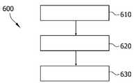
[0061]도 6에서 개략적으로 예시된 실시예에 따르면, 진공 챔버에서 기판을 코팅하기 위한 방법(600)이 제공된다. 방법은, 도 6에서 참조 부호 610에 의해 표시된 바와 같이, 스퍼터 소스에 대해 제 1 프로세스 가스 환경을 제공하는 단계, 및 제 1 프로세스 가스 환경에서 스퍼터 소스로부터 스퍼터 재료를 스퍼터링하는 단계를 포함하며, 여기서 스퍼터 소스는, 기판에 대해 제 1 포지션에 로케이팅된다. 방법은, 도 6에서 참조 부호 620에 의해 표시된 바와 같이, 진공 챔버에 대해 스퍼터 소스를 이동시키는 단계를 포함한다. 방법은, 도 6에서 참조 부호 630에 의해 표시된 바와 같이, 스퍼터 소스에 대해, 제 1 프로세스 가스 환경과 상이한 제 2 프로세스 가스 환경을 제공하는 단계, 및 제 2 프로세스 가스 환경에서 스퍼터 소스로부터 스퍼터 재료를 스퍼터링하는 단계를 더 포함하며, 여기서 스퍼터 소스는, 기판에 대해 제 2 포지션에 로케이팅된다.[0061]According to the embodiment schematically illustrated in FIG. 6, a
[0062]제 1 프로세스 가스 환경 및 제 2 프로세스 가스 환경은, 스퍼터 소스(들)의 타겟(들)에서의 국부적인 스퍼터 조건들이 일정하게 유지되도록 이루어질 수 있다. 다시 말해서, 스퍼터 프로세스의 작동 지점은 제 1 및 제 2 포지션에서, 그리고 특히, 또한, 제 1 포지션과 제 2 포지션 사이의 임의의 포지션들에서 유지될 수 있다. 스퍼터 소스는, 스퍼터 재료가 스퍼터링되는 동안 이동될 수 있는데, 예컨대, 연속적으로 그리고/또는 균일하게 이동될 수 있다. 따라서, 스퍼터 소스의 프로세스 가스 환경은, 기판에 대한, 또는 본원에서 설명된 바와 같이 진공 프로세스 챔버의 임의의 고정된 컴포넌트들, 예컨대, 기판 안내 시스템에 대한 스퍼터 소스의 현재 포지션에 기초하여 맞춤조절될 수 있다. 프로세스 가스 환경은, 본원에서 설명되는 바와 같이, 스퍼터 조립체의, 스퍼터 소스(들)의, 그리고/또는 가스 유입구 조립체의 가스 유입구들의 연속적인 병진 운동과 조화를 이루어 연속적으로 맞춤조절될 수 있다.[0062]The first process gas environment and the second process gas environment may be such that the local sputter conditions at the target (s) of the sputter source (s) are kept constant. In other words, the operating point of the sputter process can be maintained at the first and second positions, and more particularly, at any positions between the first position and the second position. The sputter source can be moved while the sputter material is sputtered, for example, can be moved continuously and / or uniformly. Thus, the process gas environment of the sputter source may be tailored based on the current position of the sputter source relative to the substrate, or any fixed components of the vacuum process chamber, e.g., the substrate guidance system, as described herein . The process gas environment can be continuously tuned in harmony with the continuous translational motion of the sputter source (s), and / or gas inlets of the gas inlet assembly, as described herein.
[0063]제 1 프로세스 가스 환경은, 프로세스 가스 파라미터들의 제 1 세트에 의해 결정될 수 있다. 프로세스 가스 파라미터들의 제 1 세트는 이하의 항목: 제 1 프로세스 가스 조성, 제 1 프로세스 가스 환경 내로의 제 1 내측으로의 전체 프로세스 가스 유동, 제 1 프로세스 가스 환경 내로의 내측으로의 부분적인 프로세스 가스 유동들의 제 1 분배, 제 1 프로세스 가스 환경 밖으로의 제 1 외측으로의 전체 가스 유동, 및 제 1 프로세스 가스 환경 밖으로의 외측으로의 부분적인 가스 유동들의 제 1 분배 중 적어도 하나를 포함할 수 있다. 제 2 프로세스 가스 환경은, 프로세스 가스 파라미터들의 제 2 세트에 의해 결정될 수 있다. 프로세스 가스 파라미터들의 제 2 세트는 이하의 항목: 제 2 프로세스 가스 조성, 제 2 프로세스 가스 환경 내로의 제 2 내측으로의 전체 프로세스 가스 유동, 제 2 프로세스 가스 환경 내로의 내측으로의 부분적인 프로세스 가스 유동들의 제 2 분배, 제 2 프로세스 가스 환경 밖으로의 제 2 외측으로의 전체 가스 유동, 및 제 2 프로세스 가스 환경 밖으로의 외측으로의 부분적인 가스 유동들의 제 2 분배 중 적어도 하나를 포함할 수 있다. 제 2 프로세스 가스 환경은, 이하의 항목들: 제 2 가스 조성은 제 1 가스 조성과 상이할 수 있음; 제 2 내측으로의 전체 프로세스 가스 유동은 제 1 내측으로의 전체 프로세스 가스 유동과 상이할 수 있음; 내측으로의 부분적인 프로세스 가스 유동들의 제 2 분배는 내측으로의 부분적인 프로세스 가스 유동들의 제 1 분배와 상이할 수 있음; 제 2 외측으로의 전체 가스 유동은 제 1 외측으로의 전체 가스 유동과 상이할 수 있음; 및 외측으로의 부분적인 가스 유동들의 제 2 분배는 외측으로의 부분적인 가스 유동들의 제 1 분배와 상이할 수 있음 중 적어도 하나가 유지된다는 점에서, 제 1 프로세스 가스 환경과 상이할 수 있다.[0063]The first process gas environment may be determined by a first set of process gas parameters. The first set of process gas parameters includes at least one of the following: a first process gas composition, a first process gas flow into a first process gas environment, a second process gas flow inward into a first process gas environment, A first distribution of the first process gas environment, a first gas flow of the first process gas environment, a first gas flow of the first process gas environment, and a first distribution of the partial gas flows outward of the first process gas environment. The second process gas environment may be determined by a second set of process gas parameters. The second set of process gas parameters includes at least one of the following: a second process gas composition, a total process gas flow to a second inside of the second process gas environment, a partial process gas flow inward into the second process gas environment At least one of a second distribution of the first process gas environment, a second distribution of the second process gas environment, a total gas flow to the second outside of the second process gas environment, and a second distribution of partial gas flows to the outside out of the second process gas environment. The second process gas environment may include the following items: the second gas composition may be different from the first gas composition; The entire process gas flow to the second inside may be different from the entire process gas flow to the first inside; The second distribution of partial process gas flows into the interior may be different from the first distribution of partial process gas flows into the interior; The total gas flow to the second outward may be different from the total gas flow to the first outward; And a second distribution of partial gas flows to the outside may be different from a first distribution of partial gas flows to the outside of the first process gas environment.
[0064]시간에서의 제 1 순간에 또는 시간의 제 1 기간 동안에, 제 1 프로세스 가스 환경은, 제 1 양으로 그리고 제 1 분배로 제 1 프로세스 가스 조성을 포함할 수 있다. 방법은, 시간에서의 제 1 순간에 또는 시간의 제 1 기간 동안에 제 1 프로세싱 환경에서 제 1 양의 프로세스 가스를 제공하기 위해, 내측으로의 전체 프로세스 가스 유동 및/또는 외측으로의 전체 가스 유동을 제어하는 단계를 포함할 수 있다. 방법은, 특정 관계로, 예컨대, 가스들의 용적 백분율들의 측면으로 표현된 관계로 가스들을 혼합함으로써 제 1 프로세스 가스 조성을 제어하는 단계를 포함할 수 있다. 방법은, 가스 유입구들을 통한 진공 프로세스 챔버 내로의 프로세스 가스의 내측으로의 부분적인 유동들을 제어하는 것에 의해 그리고/또는 진공 프로세스 챔버의 가스 배출구들을 통한 가스의 외측으로의 부분적인 유동들을 제어하는 것에 의해, 시간에서의 제 1 순간에 또는 시간의 제 1 기간 동안에 제 1 프로세스 가스 환경에서 프로세스 가스의 제 1 분배를 제어하는 단계를 포함할 수 있다. 시간에서의 제 2 순간에 또는 시간의 제 2 기간 동안에, 제 2 프로세스 가스 환경은, 제 2 양으로 그리고 제 2 분배로 제 2 프로세스 가스 조성을 포함할 수 있다. 시간에서의 제 2 순간에 또는 시간의 제 2 기간 동안에 제 2 프로세스 가스 환경에서의 프로세스 가스의, 제 2 양, 제 2 프로세스 가스 조성, 및 제 2 분배는, 제 1 양, 제 1 프로세스 가스 조성, 및 제 1 분배에 관하여 본원에서 설명된 바와 같이 제어될 수 있다. 제 2 가스 조성은 제 1 가스 조성과 상이할 수 있다. 대안적으로 또는 부가적으로, 제 2 양은 제 1 양과 상이할 수 있다. 대안적으로 또는 부가적으로, 제 1 분배는 제 2 분배와 상이할 수 있다.[0064]At a first instant in time or during a first period of time, the first process gas environment may comprise a first process gas composition in a first amount and in a first dispense. The method may further include determining a total process gas flow inward and / or an overall gas flow outward to provide a first amount of process gas in a first processing environment at a first moment in time or during a first period of time And a step of controlling. The method may include controlling the first process gas composition by mixing gases in a relationship expressed, for example, in terms of volume percentages of gases. The method may be performed by controlling partial flows inward of the process gas into the vacuum process chamber through the gas inlets and / or by controlling partial flows outward of the gas through the gas outlets of the vacuum process chamber , Controlling the first distribution of the process gas in a first process gas environment at a first moment in time or during a first period of time. At a second instant in time or during a second period of time, the second process gas environment may comprise a second process gas composition in a second amount and in a second dispense. The second quantity, the second process gas composition, and the second dispense of the process gas in the second process gas environment at the second instant in time or during the second period of time may comprise a first quantity, a first process gas composition , And the first distribution, as described herein. The second gas composition may be different from the first gas composition. Alternatively or additionally, the second amount may be different from the first amount. Alternatively or additionally, the first distribution may be different from the second distribution.
[0065]제 1 포지션에 제공되는 제 1 프로세스 가스 환경 및 제 2 포지션에 제공되는 제 2 프로세스 가스 환경은, 스퍼터 재료를 스퍼터링하는 작동 지점을 일정하게 유지하도록 선택된다. 프로세스 가스 환경은, 스퍼터 프로세스의 작동 지점을 안정적으로 유지하기 위해, 가스 유입구 조립체의 가스 유입구들의 그리고/또는 스퍼터 소스(들)의 현재 포지션에 기초하여 연속적으로 맞춤조절될 수 있다.[0065]The first process gas environment provided in the first position and the second process gas environment provided in the second position are selected to maintain a constant operating point for sputtering the sputter material. The process gas environment can be continuously adjusted based on the current position of the gas inlet (s) and / or the sputter source (s) of the gas inlet assembly to stably maintain the operating point of the sputter process.
[0066]제 1 프로세스 가스 환경은 스퍼터 소스에 그리고 N개의 추가적인 스퍼터 소스들에 제공될 수 있으며, 여기서 N은 본원에서 설명되는 바와 같을 수 있다. 제 2 프로세스 가스 환경은 스퍼터 소스에 그리고 N개의 추가적인 스퍼터 소스들에 제공될 수 있다. 가스 유입구들, 예컨대, 본원에서 설명되는 가스 유입구 조립체의 M개의 가스 유입구들은, 프로세스 가스를 전달하고, 제 1 포지션에서 제 1 프로세스 가스 환경을, 제 2 포지션에서 제 2 프로세스 가스 환경을, 또는 스퍼터 소스(들)의 임의의 포지션에서 임의의 다른 프로세스 가스 환경을 생성하는 데에 사용될 수 있다.[0066]A first process gas environment may be provided to the sputter source and to N additional sputter sources, where N may be as described herein. A second process gas environment may be provided to the sputter source and to the N additional sputter sources. The gas inlets, e.g., the M gas inlets of the gas inlet assembly described herein, are configured to transfer the process gas, deliver a first process gas environment at a first position, a second process gas environment at a second position, And may be used to create any other process gas environment at any position of the source (s).
[0067]본원에서 설명된 바와 같은, 기판을 코팅하기 위한 방법의 스퍼터 프로세스는, 본원에서 설명되는 실시예들에 따른, 기판을 코팅하기 위한 장치의 컴포넌트들의 기능들 중 임의의 기능을 수행하는 단계를 포함할 수 있다. 추가적인 실시예들은, 기판을 코팅하기 위한, 본원에서 설명되는 바와 같은 장치의 사용에 관한 것이다. 장치의 사용은, 본원에서 설명되는 방법의 특징들 중 하나, 몇몇, 또는 전부를 포함할 수 있으며, 장치의 대응하는 컴포넌트들은 스퍼터 프로세스를 수행하는 데에 사용된다.[0067]The sputter process of the method for coating a substrate, as described herein, comprises the step of performing any of the functions of the components of the apparatus for coating a substrate, according to embodiments described herein . Additional embodiments are directed to the use of an apparatus as described herein for coating a substrate. The use of the device may include one, some, or all of the features of the method described herein, and the corresponding components of the device are used to perform the sputter process.
[0068]본 개시물의 적어도 몇몇 양태들은 특히, 기판들의 증착, 패터닝, 및 처리 그리고 코팅들에서 사용되는 장비, 프로세스들, 및 재료들을 수반하는 기판 코팅 기술 해결책들에 관한 것으로, 대표적인 예들은: 반도체 및 유전체 재료들 및 디바이스들, 실리콘-계(silicon-based) 웨이퍼들, 평판 디스플레이들(예컨대, TFT들), 마스크들 및 필터들, 에너지 변환 및 저장소(예컨대, 광전지들, 연료 전지들, 및 배터리들), 솔리드-스테이트 조명(solid-state lighting)(예컨대, LED들 및 OLED들), 자기 및 광학 저장소, MEMS(micro-electro-mechanical systems) 및 NEMS(nano-electro-mechanical systems), MOEMS(micro-optic 및 opto-electro-mechanical systems), 마이크로-광학(micro-optic) 및 광전자 디바이스들(optoelectronic devices),투명( transparent) 기판들, 건축 및 자동차 유리들, 금속 및 폴리머 포일들(foils) 및 패키징(packaging)을 위한 금속화(metallization) 시스템들, 및 마이크로- 및 나노-몰딩을 수반하는 애플리케이션들을 포함하지만, 이제 제한되지 않는다.[0068]At least some aspects of the disclosure particularly relate to substrate coating techniques solutions involving deposition, patterning, and processing of substrates and equipment, processes, and materials used in coatings, with representative examples being semiconductor and dielectric materials Devices and silicon-based wafers, flat panel displays (e.g., TFTs), masks and filters, energy conversion and storage (e.g., photovoltaic cells, fuel cells, and batteries) , Solid-state lighting (e.g. LEDs and OLEDs), magnetic and optical storage, micro-electro-mechanical systems (MEMS) and nano-electro-mechanical systems (NEMS) optical and opto-electro-mechanical systems, micro-optic and optoelectronic devices, transparent substrates, architectural and automotive glasses, metal and polymer foils and packaging (packaging) Metallization systems for micro-and nano-molding, and applications involving micro-and nano-molding.
[0069]전술한 내용은 몇몇 실시예들에 관한 것이지만, 다른 그리고 추가적인 실시예들이, 이하의 청구항들에 의해 결정되는 범위를 벗어나지 않고 안출될 수 있다.[0069]While the foregoing is directed to some embodiments, other and further embodiments may be devised without departing from the scope of the invention as defined by the following claims.
Claims (15)
Translated fromKorean상기 장치는,
진공 프로세스 챔버를 포함하고, 상기 진공 프로세스 챔버는,
하나 또는 그 초과의 프로세스 가스 소스들에 연결하기 위해 적어도 하나의 커넥터를 포함하는 가스 유입구 조립체;
스퍼터 소스를 포함하는 스퍼터 조립체 - 상기 스퍼터 조립체는 상기 진공 프로세스 챔버에 대해 이동 가능함 -; 를 포함하며, 그리고
상기 장치는,
상기 진공 프로세스 챔버에서 상기 스퍼터 소스의 또는 상기 스퍼터 조립체의 현재 포지션에 따라, 상기 가스 유입구 조립체를 통해 상기 진공 프로세스 챔버 내에 도입되는 프로세스 가스의 유동, 상기 가스 유입구 조립체를 통해 상기 진공 프로세스 챔버 내로 도입되는 프로세스 가스의 조성, 상기 가스 유입구 조립체를 통해 상기 진공 프로세스 챔버 내로 도입되는 프로세스 가스의 분배, 및 진공 챔버 밖으로 펌핑되는 가스 유동 중 적어도 하나를 제어하도록 구성된 제어기를 포함하는,
기판을 코팅하기 위한 장치.An apparatus for coating a substrate,
The apparatus comprises:
And a vacuum process chamber,
A gas inlet assembly including at least one connector for connecting to one or more process gas sources;
A sputter assembly comprising a sputter source, the sputter assembly being movable relative to the vacuum process chamber; And
The apparatus comprises:
A flow of process gas introduced into the vacuum process chamber through the gas inlet assembly according to the current position of the sputter source in the vacuum process chamber or into the vacuum process chamber through the gas inlet assembly A controller configured to control at least one of a composition of the process gas, a distribution of the process gas introduced into the vacuum process chamber through the gas inlet assembly, and a gas flow pumped out of the vacuum chamber.
An apparatus for coating a substrate.
상기 스퍼터 소스는 회전 가능한 타겟을 포함하는,
기판을 코팅하기 위한 장치.The method according to claim 1,
Wherein the sputter source comprises a rotatable target,
An apparatus for coating a substrate.
상기 진공 프로세스 챔버에 배열된 기판 안내 시스템을 포함하고, 상기 기판 안내 시스템은, 코팅 동안 기판을 지지하기 위해, 그리고 상기 기판을 상기 진공 프로세스 챔버 안으로 그리고 밖으로 이동시키기 위해 배열되며, 상기 스퍼터 조립체는 상기 기판 안내 시스템을 따라 이동 가능한,
기판을 코팅하기 위한 장치.3. The method according to claim 1 or 2,
Wherein the substrate guide system is arranged to support a substrate during coating and to move the substrate into and out of the vacuum process chamber, the sputter assembly comprising: A substrate guide system,
An apparatus for coating a substrate.
상기 스퍼터 조립체에 커플링된 구동 시스템을 포함하고, 상기 구동 시스템은, 상기 스퍼터 조립체의 병진 운동(translational movement)을 달성하도록(effect) 구성되며, 특히, 상기 제어기는, 상기 스퍼터 조립체의 병진 운동을 제어하기 위해, 상기 구동 시스템에 커플링되는,
기판을 코팅하기 위한 장치.4. The method according to any one of claims 1 to 3,
And a drive system coupled to the sputter assembly, wherein the drive system is configured to effect translational movement of the sputter assembly, and in particular, the controller is configured to control the translational movement of the sputter assembly Coupled to said drive system,
An apparatus for coating a substrate.
상기 가스 유입구 조립체는 상기 스퍼터 조립체와 함께 이동 가능하며, 특히, 상기 가스 유입구 조립체 및 상기 스퍼터 조립체는 캐리지(carriage) 상에 장착되는,
기판을 코팅하기 위한 장치.5. The method according to any one of claims 1 to 4,
Wherein the gas inlet assembly is movable with the sputter assembly, and in particular, the gas inlet assembly and the sputter assembly are mounted on a carriage,
An apparatus for coating a substrate.
상기 가스 유입구 조립체는, 상기 프로세스 가스를 상기 진공 프로세스 챔버 내에 도입하기 위해, M개의 가스 유입구들을 포함하며, M은 1 내지 15 범위에 있고, 상기 제어기는, 상기 M개의 가스 유입구들의 포지션에 따라, 상기 M개의 가스 유입구들을 통해 유동하는, 상기 프로세스 가스의 분배, 상기 프로세스 가스의 조성, 및 상기 프로세스 가스의 유동 중 적어도 하나를 제어하도록 구성되는,
기판을 코팅하기 위한 장치.6. The method according to any one of claims 1 to 5,
Wherein the gas inlet assembly comprises M gas inlets for introducing the process gas into the vacuum process chamber and wherein M is in the range of 1 to 15, And at least one of a distribution of the process gas, a composition of the process gas, and a flow of the process gas flowing through the M gas inlets,
An apparatus for coating a substrate.
상기 스퍼터 조립체는 N개의 추가적인 스퍼터 소스들을 포함하며, N은 1 내지 10 범위에 있고, 상기 N개의 추가적인 스퍼터 소스들은 상기 스퍼터 소스와 동일한 유형인,
기판을 코팅하기 위한 장치.7. The method according to any one of claims 1 to 6,
Wherein the sputter assembly comprises N additional sputter sources, wherein N is in the range of 1 to 10, and wherein the N additional sputter sources are of the same type as the sputter source,
An apparatus for coating a substrate.
코팅 동안에 상기 기판 또는 기판 캐리어를 쉴딩하기(shielding) 위해, 상기 기판 안내 시스템에 배열된 쉴드(shield);
상기 진공 프로세스 챔버의 챔버 벽; 및
상기 진공 프로세스 챔버의 하나 또는 그 초과의 가스 배출구들에 연결된 하나 또는 그 초과의 진공 펌프들 중 적어도 하나를 더 포함하고,
상기 제어기는, 상기 스퍼터 조립체 또는 상기 스퍼터 소스가 상기 기판과 대면하는지 또는 상기 쉴드 또는 상기 챔버 벽과 대면하는지에 따라, 상기 프로세스 가스의 유동, 상기 프로세스 가스의 조성, 상기 프로세스 가스의 분배, 및 상기 하나 또는 그 초과의 진공 펌프들에 의해 상기 진공 프로세스 챔버 밖으로 펌핑되는 전체 가스 유동 및 상기 하나 또는 그 초과의 가스 배출구들을 통해 상기 진공 프로세스 챔버 밖으로 펌핑되는 부분적인 가스 유동들의 분배 중 적어도 하나를 변화시키도록 구성되는,
기판을 코팅하기 위한 장치.8. The method according to any one of claims 1 to 7,
A shield disposed in the substrate guiding system for shielding the substrate or substrate carrier during coating;
A chamber wall of the vacuum process chamber; And
Further comprising at least one of one or more vacuum pumps connected to one or more gas outlets of the vacuum process chamber,
Wherein the controller controls the flow of the process gas, the composition of the process gas, the distribution of the process gas, and the flow rate of the process gas, depending on whether the sputter assembly or the sputter source faces the substrate or faces the shield or the chamber wall. Varying at least one of an entire gas flow pumped out of the vacuum process chamber by one or more vacuum pumps and a distribution of partial gas flows pumped out of the vacuum process chamber through the one or more gas outlets ≪ / RTI >
An apparatus for coating a substrate.
상기 스퍼터 소스에 전력을 인가하기 위한 전력 소스를 포함하고,
상기 제어기는, 상기 진공 프로세스 챔버에서 상기 스퍼터 소스의 또는 상기 스퍼터 조립체의 현재 포지션에 따라, 상기 전력 소스에 의해 상기 스퍼터 소스에 인가되는 전력을 제어하도록 구성되는,
기판을 코팅하기 위한 장치.9. The method according to any one of claims 1 to 8,
And a power source for applying power to the sputter source,
Wherein the controller is configured to control power applied to the sputter source by the power source in accordance with the current position of the sputter source or the sputter assembly in the vacuum process chamber.
An apparatus for coating a substrate.
상기 방법은,
스퍼터 소스에 대해 제 1 프로세스 가스 환경을 제공하는 단계;
상기 제 1 프로세스 가스 환경에서 상기 스퍼터 소스로부터 스퍼터 재료를 스퍼터링하는 단계 - 상기 스퍼터 소스는, 기판에 대해 제 1 포지션에 로케이팅됨 -;
상기 진공 챔버에 대해 상기 스퍼터 소스를 이동시키는 단계;
상기 스퍼터 소스에 대해, 상기 제 1 프로세스 가스 환경과 상이한 제 2 프로세스 가스 환경을 제공하는 단계; 및
상기 제 2 프로세스 가스 환경에서 상기 스퍼터 소스로부터 스퍼터 재료를 스퍼터링하는 단계 - 상기 스퍼터 소스는, 기판에 대해 제 2 포지션에 로케이팅됨 -; 를 포함하는,
진공 챔버에서 기판을 코팅하기 위한 방법.A method for coating a substrate in a vacuum chamber,
The method comprises:
Providing a first process gas environment for the sputter source;
Sputtering a sputter material from the sputter source in the first process gas environment, the sputter source being located at a first position relative to the substrate;
Moving the sputter source relative to the vacuum chamber;
Providing, for the sputter source, a second process gas environment different than the first process gas environment; And
Sputtering a sputter material from the sputter source in the second process gas environment, the sputter source being located at a second position relative to the substrate; / RTI >
A method for coating a substrate in a vacuum chamber.
상기 스퍼터 재료가 스퍼터링되는 동안 상기 스퍼터 소스는 연속적으로 이동되고, 상기 스퍼터 소스의 상기 프로세스 가스 환경은, 상기 기판에 대한 상기 스퍼터 소스의 현재 포지션에 기초하여, 연속적으로 맞춤조절되는(adapted),
진공 챔버에서 기판을 코팅하기 위한 방법.11. The method of claim 10,
Wherein the sputter source is continuously moved while the sputter material is sputtered and the process gas environment of the sputter source is continuously adapted to be based on a current position of the sputter source relative to the substrate,
A method for coating a substrate in a vacuum chamber.
제 1 프로세스 가스 환경은, 제 1 프로세스 가스 조성, 제 1 프로세스 가스 환경 내로의 제 1 내측으로의 전체 프로세스 가스 유동, 제 1 프로세스 가스 환경 내로의 내측으로의 부분적인 프로세스 가스 유동들의 제 1 분배, 제 1 프로세스 가스 환경 밖으로의 제 1 외측으로의 전체 가스 유동, 및 제 1 프로세스 가스 환경 밖으로의 외측으로의 부분적인 가스 유동들의 제 1 분배 중 적어도 하나를 포함하는, 프로세스 가스 파라미터들의 제 1 세트에 의해 결정되며, 제 2 프로세스 가스 환경은, 제 2 프로세스 가스 조성, 제 2 프로세스 가스 환경 내로의 제 2 내측으로의 전체 프로세스 가스 유동, 제 2 프로세스 가스 환경 내로의 내측으로의 부분적인 프로세스 가스 유동들의 제 2 분배, 제 2 프로세스 가스 환경 밖으로의 제 2 외측으로의 전체 가스 유동, 및 제 2 프로세스 가스 환경 밖으로의 외측으로의 부분적인 가스 유동들의 제 2 분배 중 적어도 하나를 포함하는, 프로세스 가스 파라미터들의 제 2 세트에 의해 결정되며,
이하의 항목:
상기 제 2 가스 조성은 상기 제 1 가스 조성과 상이함;
상기 제 2 내측으로의 전체 프로세스 가스 유동은, 상기 제 1 내측으로의 전체 프로세스 가스 유동과 상이함;
상기 내측으로의 부분적인 프로세스 가스 유동들의 제 2 분배는, 상기 내측으로의 부분적인 프로세스 가스 유동들의 제 1 분배와 상이함;
상기 제 2 외측으로의 전체 가스 유동은, 상기 제 1 외측으로의 전체 가스 유동과 상이함; 및
상기 외측으로의 부분적인 가스 유동들의 제 2 분배는, 상기 외측으로의 부분적인 가스 유동들의 제 1 분배와 상이함 중 적어도 하나가 유지되는,
진공 챔버에서 기판을 코팅하기 위한 방법.The method according to claim 10 or 11,
The first process gas environment comprises a first process gas composition, an entire process gas flow into the first process gas environment into the first process gas environment, a first distribution of partial process gas flows inward into the first process gas environment, A first set of process gas parameters comprising at least one of a total gas flow out of the first process gas environment to a first out side and a first partial outgassing partial gas flows out of the first process gas environment, And the second process gas environment is determined by the second process gas composition, the entire process gas flow into the second inside of the second process gas environment, the partial process gas flows into the second process gas environment A second distribution, a total gas flow out of the second process gas environment to the second outward, Process comprising at least one of the second distribution of partial gas flow in the outer environment out of the gas, the process is determined by a second set of gas parameters,
The following items:
The second gas composition being different from the first gas composition;
Wherein the total process gas flow to the second inside differs from the total process gas flow to the first inside;
Wherein a second distribution of the partial process gas flows into the interior differs from a first distribution of the partial process gas flows into the interior;
Wherein the total gas flow to the second outward is different than the total outward gas flow to the first outward; And
Wherein a second distribution of partial gas flows outwardly is maintained at least one of a difference from a first distribution of partial gas flows outwardly,
A method for coating a substrate in a vacuum chamber.
상기 제 1 포지션에 제공되는 상기 제 1 프로세스 가스 환경 및 상기 제 2 포지션에 제공되는 상기 제 2 프로세스 가스 환경은, 스퍼터 재료를 스퍼터링하는 작동 지점을 일정하게 유지하도록 선택되는,
진공 챔버에서 기판을 코팅하기 위한 방법.13. The method according to any one of claims 10 to 12,
Wherein the first process gas environment provided in the first position and the second process gas environment provided in the second position are selected to maintain a constant operating point for sputtering the sputter material,
A method for coating a substrate in a vacuum chamber.
상기 제 1 프로세스 가스 환경을 제공하는 단계는, 상기 스퍼터 소스에 대해 그리고 N개의 추가적인 스퍼터 소스들에 대해 상기 제 1 프로세스 가스 환경을 제공하는 것을 포함하고, N은 1 내지 10 범위에 있으며, 상기 제 2 프로세스 가스 환경을 제공하는 단계는, 상기 제 2 프로세스 가스 환경을 상기 스퍼터 소스에 대해 그리고 상기 N개의 추가적인 스퍼터 소스들에 대해 제공하는 것을 포함하는,
진공 챔버에서 기판을 코팅하기 위한 방법.14. The method according to any one of claims 10 to 13,
Wherein providing the first process gas environment comprises providing the first process gas environment for the sputter source and for N additional sputter sources, wherein N ranges from 1 to 10, 2 process gas environment comprises providing the second process gas environment to the sputter source and to the N additional sputter sources.
A method for coating a substrate in a vacuum chamber.
상기 스퍼터 소스는 상기 제 2 포지션에서 상기 기판과 대면하고, 상기 스퍼터 소스는 상기 제 1 포지션에서 상기 진공 챔버의 컴포넌트, 특히, 쉴드 또는 챔버 벽과 대면하는,
진공 챔버에서 기판을 코팅하기 위한 방법.15. The method according to any one of claims 10 to 14,
Wherein the sputter source faces the substrate at the second position and the sputter source is in contact with a component of the vacuum chamber, particularly a shield or chamber wall, at the first position,
A method for coating a substrate in a vacuum chamber.
Applications Claiming Priority (1)
| Application Number | Priority Date | Filing Date | Title |
|---|---|---|---|
| PCT/EP2014/078056WO2016095975A1 (en) | 2014-12-16 | 2014-12-16 | Apparatus and method for coating a substrate with a movable sputter assembly and control over process gas parameters |
Publications (1)
| Publication Number | Publication Date |
|---|---|
| KR20170095362Atrue KR20170095362A (en) | 2017-08-22 |
Family
ID=52134167
Family Applications (1)
| Application Number | Title | Priority Date | Filing Date |
|---|---|---|---|
| KR1020177019750ACeasedKR20170095362A (en) | 2014-12-16 | 2014-12-16 | Apparatus and method for coating a substrate with a movable sputter assembly and control over process gas parameters |
Country Status (3)
| Country | Link |
|---|---|
| KR (1) | KR20170095362A (en) |
| CN (1) | CN208791746U (en) |
| WO (1) | WO2016095975A1 (en) |
Families Citing this family (2)
| Publication number | Priority date | Publication date | Assignee | Title |
|---|---|---|---|---|
| JP7220562B2 (en)* | 2018-12-27 | 2023-02-10 | キヤノントッキ株式会社 | Film forming apparatus, film forming method, and electronic device manufacturing method |
| JP7229014B2 (en)* | 2018-12-27 | 2023-02-27 | キヤノントッキ株式会社 | Film forming apparatus, film forming method, and electronic device manufacturing method |
Family Cites Families (3)
| Publication number | Priority date | Publication date | Assignee | Title |
|---|---|---|---|---|
| JP4733990B2 (en)* | 2005-02-01 | 2011-07-27 | 株式会社昭和真空 | Sputtering equipment |
| JP2009144252A (en)* | 2009-03-23 | 2009-07-02 | Canon Inc | Reactive sputtering apparatus and reactive sputtering method |
| KR101155906B1 (en)* | 2009-12-11 | 2012-06-20 | 삼성모바일디스플레이주식회사 | Sputtering Apparatus |
- 2014
- 2014-12-16WOPCT/EP2014/078056patent/WO2016095975A1/enactiveApplication Filing
- 2014-12-16CNCN201490001616.4Upatent/CN208791746U/ennot_activeExpired - Lifetime
- 2014-12-16KRKR1020177019750Apatent/KR20170095362A/ennot_activeCeased
Also Published As
| Publication number | Publication date |
|---|---|
| WO2016095975A1 (en) | 2016-06-23 |
| CN208791746U (en) | 2019-04-26 |
Similar Documents
| Publication | Publication Date | Title |
|---|---|---|
| CN1737190B (en) | Magnetic control sputtering device | |
| JP6360882B2 (en) | Deposition platform for flexible substrates and method of operation thereof | |
| KR102228608B1 (en) | Gas separation by adjustable separation wall | |
| KR102033673B1 (en) | Deposition source with adjustable electrode | |
| JP6385960B2 (en) | Common deposition platform, processing station, and method of operation thereof | |
| US20070137793A1 (en) | Processing apparatus | |
| EP3102715A1 (en) | Evaporation source for organic material, apparatus having an evaporation source for organic material, system having an evaporation deposition apparatus with an evaporation source for organic materials, and method for operating an evaporation source for organic material | |
| CN206654950U (en) | Sputter deposition apparatus for coated substrates | |
| KR102540239B1 (en) | Film formation apparatus, film formation method and manufacturing method of electronic device | |
| EP2607516B1 (en) | Method for forming a gas blocking layer | |
| CN106103787B (en) | Process gas segmentation for static reaction sputtering | |
| US20070138009A1 (en) | Sputtering apparatus | |
| JP7229014B2 (en) | Film forming apparatus, film forming method, and electronic device manufacturing method | |
| KR20170095362A (en) | Apparatus and method for coating a substrate with a movable sputter assembly and control over process gas parameters | |
| KR20170096155A (en) | Apparatus and method for coating a substrate with a movable sputter assembly and control over power parameters | |
| KR102784460B1 (en) | Film forming apparatus, film forming method and method of manufacturing electronic device | |
| KR102792322B1 (en) | Film forming apparatus, film forming method and manufacturing method of electronic device | |
| KR102784465B1 (en) | Film forming apparatus, film forming method and manufacturing method of electronic device | |
| KR102005540B1 (en) | Edge uniformity improvement in pvd array coaters | |
| KR20170134739A (en) | A method for depositing a material on a substrate, a controller for controlling a material deposition process, and a device for depositing a layer on a substrate | |
| EP1826292A1 (en) | Sputter module. | |
| KR102784474B1 (en) | Film forming apparatus, film forming method and manufacturing method of electronic device | |
| KR20240028482A (en) | tabernacle method |
Legal Events
| Date | Code | Title | Description |
|---|---|---|---|
| A201 | Request for examination | ||
| PA0105 | International application | Patent event date:20170714 Patent event code:PA01051R01D Comment text:International Patent Application | |
| PA0201 | Request for examination | ||
| PG1501 | Laying open of application | ||
| E902 | Notification of reason for refusal | ||
| PE0902 | Notice of grounds for rejection | Comment text:Notification of reason for refusal Patent event date:20190311 Patent event code:PE09021S01D | |
| E601 | Decision to refuse application | ||
| PE0601 | Decision on rejection of patent | Patent event date:20190812 Comment text:Decision to Refuse Application Patent event code:PE06012S01D Patent event date:20190311 Comment text:Notification of reason for refusal Patent event code:PE06011S01I |