KR20170094160A - Commodity dispensing apparatus - Google Patents
Commodity dispensing apparatusDownload PDFInfo
- Publication number
- KR20170094160A KR20170094160AKR1020177014443AKR20177014443AKR20170094160AKR 20170094160 AKR20170094160 AKR 20170094160AKR 1020177014443 AKR1020177014443 AKR 1020177014443AKR 20177014443 AKR20177014443 AKR 20177014443AKR 20170094160 AKR20170094160 AKR 20170094160A
- Authority
- KR
- South Korea
- Prior art keywords
- pedal
- product
- lower pedal
- state
- stopper
- Prior art date
- Legal status (The legal status is an assumption and is not a legal conclusion. Google has not performed a legal analysis and makes no representation as to the accuracy of the status listed.)
- Granted
Links
Images


Classifications
- G—PHYSICS
- G07—CHECKING-DEVICES
- G07F—COIN-FREED OR LIKE APPARATUS
- G07F11/00—Coin-freed apparatus for dispensing, or the like, discrete articles
- G07F11/02—Coin-freed apparatus for dispensing, or the like, discrete articles from non-movable magazines
- G07F11/04—Coin-freed apparatus for dispensing, or the like, discrete articles from non-movable magazines in which magazines the articles are stored one vertically above the other
- G07F11/16—Delivery means
- G07F11/24—Rotary or oscillatory members
- G—PHYSICS
- G07—CHECKING-DEVICES
- G07F—COIN-FREED OR LIKE APPARATUS
- G07F11/00—Coin-freed apparatus for dispensing, or the like, discrete articles
- G07F11/02—Coin-freed apparatus for dispensing, or the like, discrete articles from non-movable magazines
- G07F11/34—Coin-freed apparatus for dispensing, or the like, discrete articles from non-movable magazines in which the magazines are of zig-zag form
- G—PHYSICS
- G07—CHECKING-DEVICES
- G07F—COIN-FREED OR LIKE APPARATUS
- G07F9/00—Details other than those peculiar to special kinds or types of apparatus
- G07F9/02—Devices for alarm or indication, e.g. when empty; Advertising arrangements in coin-freed apparatus
- G—PHYSICS
- G07—CHECKING-DEVICES
- G07F—COIN-FREED OR LIKE APPARATUS
- G07F9/00—Details other than those peculiar to special kinds or types of apparatus
- G07F9/02—Devices for alarm or indication, e.g. when empty; Advertising arrangements in coin-freed apparatus
- G07F9/026—Devices for alarm or indication, e.g. when empty; Advertising arrangements in coin-freed apparatus for alarm, monitoring and auditing in vending machines or means for indication, e.g. when empty
Landscapes
- Physics & Mathematics (AREA)
- General Physics & Mathematics (AREA)
- Business, Economics & Management (AREA)
- Accounting & Taxation (AREA)
- Vending Machines For Individual Products (AREA)
- Control Of Vending Devices And Auxiliary Devices For Vending Devices (AREA)
Abstract
Translated fromKoreanDescription
Translated fromKorean본 발명은 상품 불출 장치에 관한 것이며, 보다 상세하게는, 예컨대 캔 음료나 페트병 음료 등의 상품을 판매하는 자동판매기에 적용되어, 상품 수납 통로에 수납된 상품을 적절하게 반출하는 상품 불출 장치에 관한 것이다.BACKGROUND OF THE
종래, 예컨대 캔 음료나 페트병 음료 등의 상품을 판매하는 자동판매기에서는, 자동판매기 본체인 본체 캐비닛의 내부의 상품 수용고에 상품 수납 랙이 설치되어 있다. 상품 수납 랙은, 상하 방향을 따라서 연장되는 상품 수납 통로와, 상품 수납 통로의 하부에 배치된 상품 반출 장치를 갖고 있다.Conventionally, for example, in a vending machine for selling a product such as a can drink or a PET bottle drink, a product storage rack is provided in a product storage box inside the body cabinet as the main body of the vending machine. The goods storage rack has a goods receiving passage extending along the vertical direction and a goods take-out device arranged at the bottom of the goods receiving passage.
상품 반출 장치는 하측 페달과 상측 페달을 구비하여 구성되어 있다. 하측 페달 및 상측 페달은, 링크를 통해 액츄에이터인 AC 솔레노이드에 연계되어 있고, AC 솔레노이드가 통전 상태가 됨으로써 각각 상품 수납 통로로 적절하게 진퇴 이동하는 것이다.The article carry-out apparatus comprises a lower pedal and an upper pedal. The lower pedal and the upper pedal are linked to an AC solenoid as an actuator through a link, and when the AC solenoid is energized, the lower pedal and the upper pedal appropriately move back and forth to the commodity receiving passages respectively.
이러한 상품 반출 장치에서는, 대기 상태에 있어서, 상측 페달이 상품 수납 통로로부터 퇴행 이동한 상태에 있는 한편, 하측 페달이 상품 수납 통로로 진출 이동한 상태에 있다. 이에 따라, 하측 페달이 상품 수납 통로에 수납되는 최하위의 상품에 맞닿아, 상품 수납 통로에 수납된 상품의 아래쪽으로의 이동이 규제되고 있다.In such a product take-out apparatus, the upper pedal is in a state of regressing from the goods receiving passage in the standby state, while the lower pedal is in the state of moving into the goods receiving passage. As a result, the lower pedal comes into contact with the lowermost commodity accommodated in the commodity receiving passage, and movement of the commodity stored in the commodity receiving passage downward is restricted.
그리고, 상품의 반출 지령이 주어진 경우, 해당하는 상품을 수납하는 상품 수납 통로의 하부의 상품 반출 장치에서는, AC 솔레노이드가 통전 상태가 됨으로써 링크를 통해 상측 페달이 상품 수납 통로로 진출 이동하여, 최하위에서 2번째의 상품에 맞닿음으로써, 그 상품, 그리고 그 상품보다도 위쪽에 수납된 상품이 아래쪽으로 향해서 이동하는 것을 규제한다. 또한, 상기 AC 솔레노이드가 통전 상태로 됨으로써 하측 페달이 상품 수납 통로로부터 퇴행 이동하여, 최하위의 상품이 유일하게 아래쪽으로 향해서 반출되고, 상품이 하측 페달을 빠져나가면 하측 페달이 스프링의 압박력에 의해 상품 수납 통로로 진출 이동한다. 그 후, AC 솔레노이드의 통전 상태가 해제되어 비통전 상태가 되면, 상품 수납 통로로 진출 이동한 하측 페달이 퇴행 이동이 규제된 상태가 되고 상측 페달이 상품 수납 통로로부터 퇴행 이동한 상태가 됨으로써 상술한 대기 상태로 복귀한다.Then, in a case where the product take-out order is given, the AC solenoid is energized so that the upper pedal moves to the product receiving passage through the link and moves at the lowest position By touching the second item, the product and the item stored above the item are regulated to move downward. Further, when the AC solenoid is energized, the lower pedal moves backward from the product receiving passage, and the lowest product is uniquely carried out downward. When the product passes the lower pedal, the lower pedal is retracted by the urging force of the spring Go to the passage to move. Thereafter, when the energized state of the AC solenoid is released to be in a non-energized state, the lower pedal moved to the commodity storing passage is regulated to be regressed, and the upper pedal is regressed from the commodity storing passage, And returns to the standby state.
또한, 상기 상품 반출 장치는, 각 페달 외에, 매진 검지 레버 및 매진 검지 스위치를 갖추고 있다. 매진 검지 레버는, 상기 상측 페달보다도 위쪽 영역에 있어서 상품 수납 통로에 대하여 진퇴 이동하는 양태로 요동 가능하게 배치되어 있으며, 압박 수단에 의해 상품 수납 통로로 진출 이동하도록 압박되고 있다. 이러한 매진 검지 레버는, 상품 수납 통로에 상품이 있는 경우에는, 그 상품에 의해 압박 수단의 압박력에 대항하여 상품 수납 통로로부터 퇴행 이동하고 있다.In addition to the respective pedals, the product carry-out apparatus is provided with a sold-out detection lever and a sold-out detection switch. The sold-out detection lever is arranged so as to be swingable in a state of moving back and forth with respect to the commodity receiving passage in a region above the upper pedal, and is pushed by the pushing means to advance and move into the commodity receiving passage. When there is a commodity in the commodity receiving passage, such a sold-out detection lever is moved backward from the commodity receiving passage against the urging force of the urging means by the commodity.
매진 검지 스위치는, 매진 검지 레버에 연계되어 있어, 매진 검지 레버가 상품 수납 통로로부터 퇴행 이동한 경우에는 오프(off) 상태가 되는 한편, 매진 검지 레버가 상품 수납 통로로 진출 이동한 경우에는 온(on) 상태가 되는 것이다. 이 매진 검지 스위치는, 온 상태가 됨으로써 상기 상품 수납 통로의 상품이 매진된 것으로 하여 매진 신호를 출력하고 있다(예컨대, 특허문헌 1 참조).The sold-out detection switch is connected to the sold-out detection lever so that the sold-out detection lever is in an off state when the sold-out detection lever moves backward from the product reception passage, on state. The sold-out detection switch outputs the sold-out signal as a result of the merchandise in the merchandise receiving passage being sold out by being turned on (see, for example, Patent Document 1).
그런데, 상술한 특허문헌 1에 제안되어 있는 상품 반출 장치에서는, 매진 검지 레버 및 매진 검지 스위치에 의해 상품 수납 통로에서의 상품의 매진을 검출할 수는 있지만, 상품 수납 통로에서의 최하위의 상품이 아래쪽으로 향해서 반출되는 것에 관해서는 돌아가는 형편에 맡겨져 있어, 상품이 확실하게 불출되었음을 검출하기는 어려웠다.However, in the product take-out device proposed in the above-described
그래서, 상품 반출 장치로부터 상품이 확실하게 불출되었음을 검출하기 위해서는, 다른 곳에 센서 등을 설치하여 상품의 통과를 검출할 필요가 있어, 결과적으로 부품 개수의 증가에 의한 제조 비용의 증가를 초래해 버려 바람직한 것이 아니다.Therefore, in order to detect that the product has been reliably discharged from the product carry-out apparatus, it is necessary to install a sensor or the like elsewhere to detect passage of the product, resulting in an increase in the manufacturing cost due to an increase in the number of parts, It is not.
본 발명은, 이러한 실정을 감안하여, 상품 수납 통로로부터의 상품의 불출을 확실하게 검출할 수 있는 상품 불출 장치를 제공하는 것을 목적으로 한다.SUMMARY OF THE INVENTION In view of the foregoing, it is an object of the present invention to provide a product dispensing apparatus capable of reliably detecting dispensation of a product from a product storage passageway.
상기 목적을 달성하기 위해서, 본 발명에 따른 상품 불출 장치는, 투입된 상품을 상하 방향을 따라서 수납하는 상품 수납 통로에 대하여 선단부가 진퇴 이동하는 양태로 베이스에 요동 가능하게 배치된 하측 페달과, 상기 하측 페달보다도 위쪽 영역에 있어서 상기 상품 수납 통로에 대하여 선단부가 진퇴 이동하는 양태로 상기 베이스에 요동 가능하게 배치된 상측 페달을 가지고, 대기 상태에 있어서는, 상기 상측 페달을 상기 상품 수납 통로로부터 퇴행 이동시키면서 상기 하측 페달을 상기 상품 수납 통로로 진출 이동시켜 상기 하측 페달이 상면에 최하위의 상품이 놓여 제1 대기 자세가 됨으로써 상기 상품이 아래쪽으로 향해서 이동하는 것을 규제하는 한편, 구동하는 경우에는, 상기 상측 페달을 상기 상품 수납 통로로 진출 이동시켜 최하위에서 2번째의 상품에 맞닿게 하면서 상기 하측 페달을 상기 상품 수납 통로로부터 퇴행 이동시킴으로써 최하위의 상품을 아래쪽으로 향해서 반출하는 상품 반출 장치를 구비한 상품 불출 장치에 있어서, 상기 하측 페달은, 상기 상품 수납 통로로 진출 이동한 상태에 있어서 상면에 상품이 놓이지 않는 경우에는, 상기 제1 대기 자세보다도 상기 선단부가 위쪽에 위치하는 제2 대기 자세로 되는 것이고, 상기 하측 페달이 상기 제2 대기 자세로 되는 경우에 제1 상태가 되는 한편, 상기 하측 페달이 상기 제2 대기 자세 이외의 것으로 되는 경우에 제2 상태가 되는 매진 검지 스위치와, 상기 상품 반출 장치가 구동하는 경우에, 상기 매진 검지 스위치가 제1 상태가 됨으로써 상기 상품 수납 통로로부터 상품이 불출되었음을 판정하는 제어 수단을 구비한 것을 특징으로 한다.In order to achieve the above object, a product dispensing apparatus according to the present invention comprises a lower pedal arranged to be swingable on a base in such a manner that a distal end portion thereof moves forward and backward with respect to a product accommodating passage accommodating an inserted commodity along a vertical direction, And an upper pedal which is swingably disposed on the base in such a manner that a distal end portion of the upper pedal moves forward and backward relative to the product storage passage in an area above the pedal, The lower pedal is advanced to the goods receiving passage and the lower pedal is placed on the upper surface so that the lowest commodity is placed in the first waiting posture so that the commodity is prevented from moving downward while the upper pedal is moved, And moves to the merchandise storing passage to move to the
또한 본 발명은, 상기 상품 불출 장치에 있어서, 자신의 중심축 둘레로 회전 가능하게 배치되며 또한 대기 위치에 위치하는 경우에는 상기 상품 반출 장치를 대기 상태로 하는 한편, 상기 대기 위치로부터 회전하는 경우에는 상기 상품 반출 장치를 구동시키는 출력 부재를 구비하고, 상기 제어 수단은, 상기 출력 부재를 상기 대기 위치로부터 회전시키는 경우에, 상기 매진 검지 스위치가 제1 상태가 됨으로써 상기 상품 수납 통로로부터 상품이 불출되었음을 판정하는 것을 특징으로 한다.Further, according to the present invention, in the above-described product dispensing apparatus, when the product dispensing apparatus is disposed so as to be rotatable about its own central axis and is located at a standby position, the product dispensing apparatus is put in a standby state, When the output member is rotated from the standby position, when the sold-out detection switch is in the first state, it is determined that the product has been dispensed from the product storage passage And a determination is made.
또한 본 발명은, 상기 상품 불출 장치에 있어서, 상기 제어 수단은, 미리 설정된 설정 시간 내에 상기 대기 위치로부터 회전시킨 상기 출력 부재가 상기 대기 위치로 복귀하지 않는 경우에 있어서, 상기 설정 시간 내에 상기 매진 검지 스위치가 제1 상태가 될 때는 상기 설정 시간 경과 후에도 상기 출력 부재를 계속하여 같은 방향으로 회전시키는 한편, 상기 설정 시간 내에 상기 매진 검지 스위치가 제1 상태가 되지 않을 때에는 상기 출력 부재의 회전을 정지시켜 미리 정해진 대기 시간 내에 상기 매진 검지 스위치가 제1 상태가 되는지 여부를 판정하는 것을 특징으로 한다.Further, in the above-described goods dispensing apparatus, when the output member rotated from the standby position within a preset set time does not return to the standby position, When the switch is in the first state, the output member is continuously rotated in the same direction after the elapse of the set time, and when the sold out detection switch does not become the first state within the set time, the rotation of the output member is stopped And determines whether or not the soldering detection switch becomes the first state within a predetermined waiting time.
또한 본 발명은, 상기 상품 불출 장치에 있어서, 상기 제어 수단은, 상기 대기 시간 내에 상기 매진 검지 스위치가 제1 상태가 되는 경우에는, 상기 대기 시간 경과 후에 상기 출력 부재를 같은 방향으로 회전시키는 한편, 상기 대기 시간 내에 상기 매진 검지 스위치가 제1 상태로 되지 않는 경우에는, 상기 출력 부재를 역방향으로 회전시키는 것을 특징으로 한다.Further, according to the present invention, in the above product dispensing apparatus, when the soldering detection switch is in the first state within the waiting time, the control means rotates the output member in the same direction after the waiting time elapses, And the output member is rotated in the reverse direction when the sold out detection switch does not reach the first state within the waiting time.
본 발명에 따르면, 제어 수단이, 상품 반출 장치가 구동하는 경우에, 매진 검지 스위치가 제1 상태로 됨으로써 상품 수납 통로로부터 상품이 불출되었음을 판정하기 때문에, 상품 수납 통로로부터의 상품의 불출을 확실하게 검출할 수 있다고 하는 효과를 발휘한다.According to the present invention, in the case where the goods take-out device is driven, the control means judges that the sold-out detection switch is in the first state to release the goods from the goods receiving passage, And it is possible to detect the effect.
도 1은 본 발명의 실시형태인 상품 불출 장치가 적용된 자동판매기의 내부 구조를 우측에서 본 경우를 도시하는 단면 측면도이다.
도 2는 도 1에 도시한 상품 불출 장치를 우측에서 본 경우를 도시하는 측면도이다.
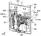
도 3은 도 1에 도시한 상품 불출 장치를 우측 전방에서 본 경우를 도시하는 사시도이다.
도 4는 도 1에 도시한 상품 불출 장치를 우측 후방에서 본 경우를 도시하는 사시도이다.
도 5는 도 2~도 4에 도시한 제1 상품 반출 장치를 우측 후방에서 본 경우를 도시하는 사시도이다.
도 6은 도 2~도 5에 도시한 제1 상품 반출 장치의 주요부를 우측에서 본 경우를 모식적으로 도시하는 설명도이다.
도 7은 도 2~도 5에 도시한 제1 상품 반출 장치의 주요부를 우측에서 본 경우를 모식적으로 도시하는 설명도이다.
도 8은 도 2~도 5에 도시한 제1 상품 반출 장치의 주요부를 우측에서 본 경우를 모식적으로 도시하는 설명도이다.
도 9는 도 2~도 5에 도시한 제1 상품 반출 장치의 베이스를 도시하는 사시도이다.
도 10은 도 9에 도시한 베이스에 부착된 베어링부 및 하네스 가이드를 도시하는 사시도이다.
도 11은 도 2~도 4에 있어서의 상품 불출 장치의 주요부를 도시하는 측면도이다.
도 12는 하측 페달이 상품 있음 대기 자세가 된 경우에 있어서의 제1 매진 링크와 제1 매진 검지 스위치의 관계를 도시하는 측면도이다.
도 13은 하측 페달이 퇴행 이동한 경우에 있어서의 제1 매진 링크와 제1 매진 검지 스위치의 관계를 도시하는 사시도이다.
도 14는 제1 상품 반출 장치에 있어서의 구동 유닛의 주요부를 도시하는 것으로, 우측 전방에서 본 경우를 도시하는 분해 사시도이다.
도 15는 제1 상품 반출 장치에 있어서의 구동 유닛의 주요부를 도시하는 것으로, 좌측 후방에서 본 경우를 도시하는 분해 사시도이다.
도 16은 도 2~도 4에 도시한 제2 상품 반출 장치를 우측 전방에서 본 경우를 도시하는 사시도이다.
도 17은 도 2~도 4, 도 16에 도시한 제2 상품 반출 장치의 주요부를 우측에서 본 경우를 모식적으로 도시하는 설명도이다.
도 18은 도 16에 도시한 제2 상품 반출 장치의 베이스를 도시하는 사시도이다.
도 19는 도 18에 도시한 베이스에 부착된 베어링부 및 가이드를 도시하는 사시도이다.
도 20은 상품 불출 장치의 특징적인 제어계를 도시하는 블록도이다.
도 21은 구동 유닛의 주요부의 작동을 전방에서 본 경우를 도시하는 설명도이다.
도 22는 구동 유닛의 주요부의 작동을 후방 정면에서 본 경우를 도시하는 설명도이다.
도 23은 제1 상품 반출 장치에서의 상품의 반출 수순을 모식적으로 도시하는 설명도이다.
도 24는 제2 상품 반출 장치에서의 상품의 반출 수순을 모식적으로 도시하는 설명도이다.
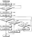
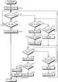
도 25는 불출 제어부가 자판기 제어부로부터 제1 상품의 반출 지령을 받은 경우에 실시하는 제1 상품 불출 판정 처리의 처리 내용을 도시하는 흐름도이다.
도 26은 도 25에 도시한 제1 상품 불출 판정 처리에 있어서의 재시행 처리(1)의 처리 내용을 도시하는 흐름도이다.
도 27은 도 25에 도시한 제1 상품 불출 판정 처리에 있어서의 복귀 처리(1)의 처리 내용을 도시하는 흐름도이다.
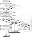
도 28은 불출 제어부가 자판기 제어부로부터 제2 상품의 반출 지령을 받은 경우에 실시하는 제2 상품 불출 판정 처리의 처리 내용을 도시하는 흐름도이다.
도 29는 도 28에 도시한 제2 상품 불출 판정 처리에 있어서의 재시행 처리(2)의 처리 내용을 도시하는 흐름도이다.
도 30은 도 28에 도시한 제2 상품 불출 판정 처리에 있어서의 복귀 처리(2)의 처리 내용을 도시하는 흐름도이다.1 is a cross-sectional side view showing the internal structure of a vending machine to which a product dispensing apparatus, which is an embodiment of the present invention, is viewed from the right side.
Fig. 2 is a side view showing the case where the product dispensing apparatus shown in Fig. 1 is viewed from the right side.
Fig. 3 is a perspective view showing a case where the product dispensing apparatus shown in Fig. 1 is viewed from the right front side.
Fig. 4 is a perspective view showing the case where the product dispensing apparatus shown in Fig. 1 is viewed from the right rear side.
Fig. 5 is a perspective view showing the case where the first goods take-out device shown in Figs. 2 to 4 is viewed from the right rear side.
Fig. 6 is an explanatory diagram schematically showing a case where the main part of the first goods take-out device shown in Figs. 2 to 5 is viewed from the right side.
Fig. 7 is an explanatory diagram schematically showing a case in which the main part of the first goods take-out device shown in Figs. 2 to 5 is viewed from the right side.
Fig. 8 is an explanatory diagram schematically showing a case in which the main part of the first product carry-out apparatus shown in Figs. 2 to 5 is viewed from the right side.
Fig. 9 is a perspective view showing the base of the first goods take-out apparatus shown in Figs. 2 to 5. Fig.
10 is a perspective view showing a bearing part and a harness guide attached to the base shown in Fig.
Fig. 11 is a side view showing the main part of the product dispensing apparatus in Figs. 2 to 4. Fig.
FIG. 12 is a side view showing the relationship between the first sold-out link and the first sold-out detection switch when the lower pedal is in the article-in-waiting state.
13 is a perspective view showing the relationship between the first sold-out link and the first sold-out detection switch in the case where the lower pedal moves backward.
Fig. 14 shows a main part of the drive unit in the first product carry-out apparatus, and is an exploded perspective view showing the case seen from the right front.
Fig. 15 shows the main part of the drive unit in the first product carry-out apparatus, and is an exploded perspective view showing the case seen from the left rear.
Fig. 16 is a perspective view showing a case where the second goods take-out device shown in Figs. 2 to 4 is viewed from the right front. Fig.
17 is an explanatory view schematically showing a case where the main part of the second product carry-out apparatus shown in Figs. 2 to 4 and Fig. 16 is viewed from the right side.
18 is a perspective view showing the base of the second goods carry-out apparatus shown in Fig.
19 is a perspective view showing a bearing portion and a guide attached to the base shown in Fig.
20 is a block diagram showing a characteristic control system of the product dispensing apparatus.
21 is an explanatory view showing a case where the operation of the main part of the drive unit is viewed from the front.
22 is an explanatory diagram showing a case in which the operation of the main part of the drive unit is viewed from the rear front.
Fig. 23 is an explanatory diagram schematically showing a procedure of taking out a product from the first product takeout apparatus. Fig.
FIG. 24 is an explanatory diagram schematically showing a procedure of taking out a product in the second goods takeout apparatus. FIG.
Fig. 25 is a flowchart showing the processing contents of the first product dispensing determination process performed when the dispensing control unit receives the instruction to export the first product from the vending machine control unit.
Fig. 26 is a flowchart showing contents of the re-enforcement process (1) in the first product dispense determination process shown in Fig.
Fig. 27 is a flowchart showing the processing contents of the return processing (1) in the first product dispensing determination processing shown in Fig.
28 is a flowchart showing the processing contents of the second product dispensing determination process performed when the dispensing control unit receives a second product dispensing instruction from the vending machine control unit.
Fig. 29 is a flowchart showing contents of the re-enforcement process (2) in the second product dispense determination process shown in Fig.
Fig. 30 is a flowchart showing the processing contents of the return processing (2) in the second product dispensing determination processing shown in Fig.
이하에 첨부 도면을 참조하여 본 발명에 따른 상품 불출 장치의 적합한 실시형태에 관해서 상세히 설명한다.BEST MODE FOR CARRYING OUT THE INVENTION Hereinafter, preferred embodiments of a product dispensing apparatus according to the present invention will be described in detail with reference to the accompanying drawings.
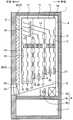
도 1은 본 발명의 실시형태인 상품 불출 장치가 적용된 자동판매기의 내부 구조를 우측에서 본 경우를 도시하는 단면 측면도이다. 여기서 예시하는 자동판매기는, 상품을 냉각 혹은 가열한 상태로 판매하는 것으로, 본체 캐비닛(1), 외부 도어(2) 및 내부 도어(3)를 구비하여 구성되어 있다.1 is a cross-sectional side view showing the internal structure of a vending machine to which a product dispensing apparatus, which is an embodiment of the present invention, is viewed from the right side. The vending machine exemplified here sells a product in a state in which it is cooled or heated and comprises a
본체 캐비닛(1)은, 복수의 강판을 적절하게 조합함으로써 앞면이 개구된 직방체 형상으로 구성된 것으로, 그 내부에 단열 구조의 상품 수용고(4)를 갖고 있다. 외부 도어(2)는, 본체 캐비닛(1)의 앞면 개구를 덮기 위한 것으로, 본체 캐비닛(1)의 일측 가장자리부에 개폐 가능하게 배치되어 있다. 이 외부 도어(2)의 앞면에는, 디스플레이 윈도우, 상품 선택 버튼, 지폐 삽입 관통구, 주화 투입구, 반환 레버, 일체 표시기, 주화 반환구, 상품 추출구(2a) 등, 상품을 판매할 때에 필요하게 되는 것이 설치되어 있다. 내부 도어(3)는, 상품 수용고(4)의 앞면 개구를 덮기 위한 상하 2 분할된 단열 도어이며, 외부 도어(2)보다도 안쪽이 되는 위치에 있어서 상부 단열 도어(3a)는 외부 도어(2)의 일측 가장자리부에 개폐 가능하게 배치되고, 하부 단열 도어(3b)는 본체 캐비닛(1)의 일측 가장자리부에 개폐 가능하게 배치되어 있다. 이 내부 도어(3)에 있어서의 하부 단열 도어(3b)의 하측부에는, 상품을 상품 수용고(4)의 외부로 반출하기 위한 상품 반출구(3c)가 형성되어 있다.The
또한, 상기 자동판매기에는, 상품 수용고(4)의 내부에 상품 슈터(5)가 설치되어 있고, 이 상품 슈터(5)보다도 아래쪽이 되는 영역(이하, 「열 교환 영역」이라고도 함)에 온도 조절 유닛(6)이 배치되어 있는 한편, 상품 슈터(5)보다도 위쪽이 되는 영역(이하, 「상품 수납 영역」이라고도 함)에 상품 수납 랙(10)이 배치되어 있다.The vending machine is provided with a
상품 슈터(5)는, 상품 수납 랙(10)으로부터 반출된 상품을 내부 도어(3)의 상품 반출구(3c)로 안내하기 위한 플레이트형 부재이며, 전방 측으로 향해서 점차 아래쪽으로 경사지는 양태로 배치되어 있다. 도면에는 명시하지 않지만, 이 상품 슈터(5)에는, 열 교환 영역과 상품 수납 영역 사이를 연통시키는 통기 구멍이 다수 뚫려 있다.The
온도 조절 유닛(6)은, 상품 수용고(4)의 내부 분위기를 원하는 온도 상태로 유지하기 위한 것으로, 냉동 사이클의 증발기(6a), 전열 히터(6b) 및 송풍 팬(6c)을 구비하여 구성되어 있다. 이 온도 조절 유닛(6)에 있어서는, 예컨대 냉동 사이클을 운전한 상태로 송풍 팬(6c)을 구동하면, 증발기(6a)에 있어서 냉각된 공기가 상품 슈터(5)의 통기 구멍을 통하여 위쪽으로 급송되기 때문에, 상품 수납 영역을 저온 상태로 유지할 수 있다. 한편, 전열 히터(6b)에 통전한 상태로 송풍 팬(6c)을 구동하면, 전열 히터(6b)에 의해서 가열된 공기가 상품 슈터(5)의 통기 구멍을 통하여 위쪽으로 급송되기 때문에, 상품 수납 영역을 고온 상태로 유지할 수 있다. 또한, 냉동 사이클의 압축기, 응축기 및 팽창 밸브는, 도면에는 명시하지 않지만, 모두 상품 수용고(4)의 외부가 되는 기계실(7)에 설치되어 있다.The
상기 상품 수납 랙(10)은, 앞뒤 3열로 나란하게 배치되어 있고, 한 쌍의 베이스 측판(11) 사이에 통로 구성 요소(12)가 배치됨으로써 상하 방향을 따라서 사행(蛇行) 형상으로 구성된 복수(도시하는 예에서는 2개)의 상품 수납 통로(13)를 구비하고, 이들 상품 수납 통로(13)의 내부에 상하 방향을 따라서 복수의 상품을 가로로 눕힌 자세로 수납하는 것이다. 보다 상세히 설명하면, 통로 구성 요소(12)는, 상품 수납 통로(13)의 전방 측과 후방 측에 상호 대향하도록 적절하게 배치된 것이며, 베이스 측판(11)에 고정되어 있다. 이에 따라 각 상품 수납 랙(10)에 있어서는, 2개의 상품 수납 통로(13)가 상호 앞뒤로 인접하는 양태로 형성되어 있다. 이하에서는, 하나의 상품 수납 랙(10)에 있어서, 전방 측의 상품 수납 통로(13)를 제1 상품 수납 통로(13a)라고도 부르고, 후방 측의 상품 수납 통로(13)를 제2 상품 수납 통로(13b)라고도 부르기로 한다.The goods storage racks 10 are arranged side by side in three rows of front and back and a plurality of (for example, (Two in the illustrated example) of the
또한, 통로 구성 요소(12)에는, 도면에는 명시하지 않는 플래퍼가 설치되어 있다. 플래퍼는, 상품 수납 통로(13)에 대하여 진퇴 이동하는 양태로 통로 구성 요소(12)에 요동 가능하게 배치되어 있다. 이 플래퍼는, 코일 스프링(도시하지 않음)에 압박되어 평상 상태에서는 상품 수납 통로(13)로 진출 이동한 자세가 된다. 그리고, 상품 수납 통로(13)를 통과하는 상품에 맞닿음으로써 자신은 코일 스프링의 압박력에 대항하여 사행 형상의 상품 수납 통로(13)를 따르도록 퇴행 이동하여 상기 상품의 자세를 수정하는 것이다.Further, a flapper (not shown) is provided in the
상기 상품 수납 랙(10)에 있어서는, 상품 수납 통로(13)의 상부에 톱 트레이(14)가 설치되어 있는 한편, 상품 수납 통로(13)의 하부에 상품 불출 장치(20)가 설치되어 있다.In the
톱 트레이(14)는, 평판형의 판금을 굴곡시켜 구성하는 것으로, 전방에서 후방으로 향해서 점차 아래쪽으로 경사지는 양태로 베이스 측판(11) 사이에 배치되어 있다. 이러한 톱 트레이(14)의 상면은, 투입구를 통하여 투입된 상품을 상품 수납 통로(13)까지 안내하는 상품 안내 통로(15)를 구성하고 있다.The
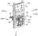
도 2~도 4는 각각 도 1에 도시한 상품 불출 장치(20)를 도시하는 것으로, 도 2는 우측에서 본 경우를 도시하는 측면도, 도 3은 우측 전방에서 본 경우를 도시하는 사시도, 도 4는 우측 후방에서 본 경우를 도시하는 사시도이다.Fig. 2 to Fig. 4 respectively show the
이들 도 2~도 4에 도시한 것과 같이, 상품 불출 장치(20)는, 한쪽의 상품 반출 장치(이하, 제1 상품 반출 장치라고도 부름)(20a)와, 다른 쪽의 상품 반출 장치(이하, 제2 상품 반출 장치라고도 부름)(20b)를 구비하고 있고, 이들 제1 상품 반출 장치(20a)와 제2 상품 반출 장치(20b)가 서로 등을 맞대고 결합되게 구성되어 있다. 또한, 이들 도 2~도 4에서는, 상품 불출 장치(20)를 구성하는 제1 상품 반출 장치(20a) 및 제2 상품 반출 장치(20b) 모두 상품이 수납되어 있지 않은 상태를 도시하고 있다.2 to 4, the
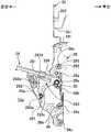
도 5는 도 2~도 4에 도시한 제1 상품 반출 장치(20a)를 우측 후방에서 본 경우를 도시하는 사시도이다. 이하에서는, 제1 상품 반출 장치(20a)의 구성에 관해서 설명하고, 그 후에 제2 상품 반출 장치(20b)에 관해서 설명한다.Fig. 5 is a perspective view showing a case where the first product carry-out
도 6~도 8은 각각 도 2~도 5에 도시한 제1 상품 반출 장치(20a)의 주요부를 우측에서 본 경우를 모식적으로 도시하는 설명도이다. 이하의 설명에서는, 이들 도 6~도 8도 적절하게 이용하면서 제1 상품 반출 장치(20a)의 구성에 관해서 설명한다.Figs. 6 to 8 are explanatory diagrams schematically showing a case in which the main part of the first product carry-out
제1 상품 반출 장치(20a)는, 제1 상품 수납 통로(13a)에 적용되는 것으로, 이 제1 상품 수납 통로(13a)의 하부에 배치되어 있다. 이 제1 상품 반출 장치(20a)는, 대향하는 통로 폭 규정판(16)과의 사이에서 상품의 거동을 제어함으로써, 반출 대기 상태에 있어서는 제1 상품 수납 통로(13a)에 상품을 수납하는 한편, 구동하는 경우에는 대응하는 상품을 하나씩 상품 슈터(5)로 반출하도록 기능하는 것으로, 베이스(21)를 구비하고 있다.The first product carry-out
베이스(21)는, 도 9에 도시한 것과 같이, 강판에 절삭 가공 및 굴곡 가공을 실시하여 구성한 것으로, 자신의 표면을 통로 폭 규정판(16)에 대향시키는 양태로 배치되어 있다. 이 베이스(21)는, 양측부가 굴곡됨으로써 측벽(21a)이 형성되어 있는 한편, 중간부에 제1 삽통 구멍(22) 및 제2 삽통 구멍(23)이 형성되어 있다. 제1 삽통 구멍(22) 및 제2 삽통 구멍(23)의 주연부는 측벽(21a)과 마찬가지로 굴곡되어 플랜지를 형성하고 있다.As shown in Fig. 9, the
제1 삽통 구멍(22)과 제2 삽통 구멍(23)은, 상호 좌우로 나란하게 형성되어 있으며 상하 치수가 동일한 크기를 갖고 있다. 이들 제1 삽통 구멍(22)과 제2 삽통 구멍(23)에서는, 제1 삽통 구멍(22)이 제2 삽통 구멍(23)의 좌측에 위치하고 있고, 제1 삽통 구멍(22)의 좌우 폭이 제2 삽통 구멍(23)의 좌우 폭보다도 큰 것이다. 또한 제1 삽통 구멍(22)과 제2 삽통 구멍(23)은, 상호 전체적으로 대략 직사각형의 형태를 이루는 관통 개구[후술하는 하측 페달(28) 및 상측 페달(29)을 베이스(21) 안으로 퇴행시키는 오목부]이며, 제1 삽통 구멍(22)의 상단부가 좌측으로 돌출되어 있고, 제2 삽통 구멍(23)의 상단부가 우측으로 돌출되어 있다. 제1 삽통 구멍(22)의 좌측 가장자리부에는 제1 좌측 베어링편(22a)이 마련되며 또한 제1 삽통 구멍(22)의 우측 가장자리부에는 제1 우측 베어링편(22b)이 마련되어 있고, 제2 삽통 구멍(23)의 좌측 가장자리부에는 제2 좌측 베어링편(23a)이 마련되며 또한 제2 삽통 구멍(23)의 우측 가장자리부에는 제2 우측 베어링편(23b)이 마련되어 있다. 이 때, 제1 좌측 베어링편(22a) 및 제2 우측 베어링편(23b)은, 제1 삽통 구멍(22) 및 제2 삽통 구멍(23)의 주연부에 형성한 플랜지에 상당하는 것이다. 또한, 제1 우측 베어링편(22b) 및 제2 좌측 베어링편(23a)은, 후술하는 베어링부(24)를 끼워 맞춰 유지하는 곳의, 베이스(21)에 일체로 형성됨과 더불어 횡단면 コ자형(불연속)으로 형성된 베어링 유지부에 있어서의 コ자형의 양 다리 부재를 이루는 축 삽통 플랜지에 형성되어 있는 것이다. 또한, 이 베어링 유지부는, 전체적으로 대략 직사각형의 형태를 이루는 제1 삽통 구멍(22)과 제2 삽통 구멍(23)으로 이루어지는 큰 관통 개구를 베이스(21)에 형성한 경우에도 베이스(21)의 강도를 유지하는 기능을 갖는다.The first through-
이러한 구성을 갖는 베이스(21)에는, 도 10에 도시한 것과 같은 베어링부(24) 및 하네스 가이드(25)가 장착되어 있다. 베어링부(24)는, 수지 재료 등에 의해 구성되는 것으로, 제1 우측 베어링편(22b)과 제2 좌측 베어링편(23a) 사이에 끼워져 있다.A bearing
하네스 가이드(25)는, 베어링부(24)와 마찬가지로 수지 재료 등에 의해 구성되는 것으로, 제2 우측 베어링편(23b)에 인접하는 양태로 베이스(21)의 우측의 측벽(21a)을 따라서 끼워져 있다. 이 하네스 가이드(25)는, 제1 상품 반출 장치(20a)에 장착되는 전장 부품의 하네스를 연장시키기 위한 것이다. 또한, 하네스 가이드(25)는, 제1 상품 반출 장치(20a)와 제2 상품 반출 장치(20b)를 상호 등을 맞대고 결합되게 할 때에 가이드 부재로서의 역할을 갖고 있다.The
이러한 하네스 가이드(25)에는, 제1 매진 검지 스위치(26) 및 제2 매진 검지 스위치(27)가 배치되어 있다.The first
제1 매진 검지 스위치(26)는, 제2 매진 검지 스위치(27)와 전후로 나란하게 배치되어 있고, 이 제2 매진 검지 스위치(27)보다도 전방 측에 위치하고 있다. 이 제1 매진 검지 스위치(26)는, 소위 푸시형 스위치이며, 도시하지 않는 스프링에 의해 기립하도록 압박된 접촉자(26a)를 갖추고 있다. 이러한 제1 매진 검지 스위치(26)는, 접촉자(26a)가 눌리지 않는 상태에서는, 오프 상태(제2 상태)로 되어 후술하는 불출 제어부(60)에 오프 신호를 송출하는 한편, 접촉자(26a)가 눌려 스프링의 압박력에 대항하여 변위하는 경우에는, 온 상태(제1 상태)가 되어 불출 제어부(60)에 온 신호를 송출하는 것이다.The first sold out
또, 본 실시형태에서는, 제1 매진 검지 스위치(26)는, 접촉자(26a)가 눌리지 않는 상태로 오프 상태가 되는 한편, 접촉자(26a)가 눌려 변위하는 경우에 온 상태가 되는 것이지만, 본 발명에서는, 제1 매진 검지 스위치(26)는, 접촉자(26a)가 눌리지 않는 상태로 온 상태가 되는 한편, 접촉자(26a)가 눌려 변위하는 경우에 오프 상태가 되는 것이라도 좋다.In the present embodiment, the first
제2 매진 검지 스위치(27)는, 제1 매진 검지 스위치(26)보다도 후방 측에 위치하고 있다. 이 제2 매진 검지 스위치(27)는, 소위 푸시형 스위치이며, 도시하지 않는 스프링에 의해 기립하도록 압박된 접촉자(27a)를 갖추고 있다. 이러한 제2 매진 검지 스위치(27)는, 접촉자(27a)가 눌리지 않는 상태에서는, 오프 상태(제2 상태)가 되어 후술하는 불출 제어부(60)에 오프 신호를 송출하는 한편, 접촉자(27a)가 눌려 스프링의 압박력에 대항하여 변위하는 경우에는, 온 상태(제1 상태)가 되어 불출 제어부(60)에 온 신호를 송출하는 것이다.The second sold out
또, 본 실시형태에서는, 제2 매진 검지 스위치(27)는, 접촉자(27a)가 눌리지 않는 상태로 오프 상태가 되는 한편, 접촉자(27a)가 눌려 변위하는 경우에 온 상태가 되는 것이지만, 본 발명에서는, 제2 매진 검지 스위치(27)는, 접촉자(27a)가 눌리지 않는 상태로 온 상태가 되는 한편, 접촉자(27a)가 눌려 변위하는 경우에 오프 상태가 되는 것이라도 좋다.In the present embodiment, the second sold out
상기 베이스(21)에는, 제1 요동 지지축(28a) 및 제2 요동 지지축(29a)이 설치되어 있다. 제1 요동 지지축(28a)은, 대략 수평 방향을 따라서 연장되는 양태로 제1 좌측 베어링편(22a), 제1 우측 베어링편(22b), 제2 좌측 베어링편(23a), 제2 우측 베어링편(23b) 및 베어링부(24)에 형성된 각 관통 구멍(22a1, 22b1, 23a1, 23b1, 24a)을 관통하여 가설된 축 형상 부재이며, 그 중간부에 하측 페달(28)을 지승(支承)하고 있다. 또한, 제1 요동 지지축(28a)의 우측 단부에는 제1 매진 링크(30)가 배치되어 있다.The
제2 요동 지지축(29a)은, 제1 요동 지지축(28a)보다도 위쪽 영역에 있어서, 대략 수평 방향을 따라서 연장되는 양태로 제1 좌측 베어링편(22a), 제1 우측 베어링편(22b), 제2 좌측 베어링편(23a), 제2 우측 베어링편(23b) 및 베어링부(24)에 형성된 각 관통 구멍(22a2, 22b2, 23a2, 23b2, 24b)을 관통하여 가설된 축 형상 부재이며, 그 중간부에 상측 페달(29)을 지승하고 있다.The first
하측 페달(28)은 플레이트형 부재이며, 기단부에 제1 요동 지지축(28a)을 삽입 관통시킴으로써 이 제1 요동 지지축(28a)의 중심축 둘레로 요동이 가능하게 되는 양태로 배치되어 있다.The
하측 페달(28)의 선단부는, 제1 요동 지지축(28a)의 직경 바깥 방향으로 향해서 연장되어 있으며, 제1 요동 지지축(28a)의 중심축 둘레로 요동한 경우에 제1 삽통 구멍(22) 및 제2 삽통 구멍(23)을 통하여 제1 상품 수납 통로(13a)로 진퇴 이동하는 것이 가능하다. 즉, 하측 페달(28)은, 제1 상품 수납 통로(13a)에 대하여 진퇴 이동하는 양태로 요동 가능하게 배치되어 있다.The distal end of the
하측 페달(28)과 베이스(21)의 사이에는 하측 페달 스프링(28b)이 개재되어 있다. 하측 페달 스프링(28b)은, 제1 상품 수납 통로(13a)에 대하여 하측 페달(28)을 진출 이동하는 방향으로 향해서 항상 압박하는 것이다. 보다 상세히 설명하면, 하측 페달 스프링(28b)은, 도 6에 도시한 것과 같이 하측 페달(28)의 선단부가 제1 요동 지지축(28a)보다도 위쪽에 위치하도록 하측 페달(28)을 대기 자세[이하, 상품 없음 대기 자세(제2 대기 자세)라고도 함]로 하게 하는 것이다. 그리고, 하측 페달 스프링(28b)은, 하측 페달(28)의 상면에 상품이 놓이는 경우에는, 도 7에 도시한 것과 같이 하측 페달(28)의 선단부가 제1 요동 지지축(28a)과 동등한 높이 레벨에 위치하도록 하측 페달(28)을 대기 자세[이하, 상품 있음 대기 자세(제1 대기 자세)라고도 함]로 하게 하는 것이다.A
이에 따라, 하측 페달(28)은, 상품 없음 대기 자세가 되는 경우에는, 상품 있음 대기 자세가 될 때보다도 선단부가 위쪽에 위치하게 된다.Thus, when the
그리고, 하측 페달(28)이 상품 없음 대기 자세로 되는 경우, 도 11에 도시한 것과 같이, 하측 페달(28)의 기단부가 제1 매진 링크(30)의 제1 매진 맞닿음부(32)에 맞닿는 결과, 제1 매진 링크(30)는, 제1 요동 지지축(28a)를 축심으로 하여 회전하고, 이에 따라 제1 매진 누름부(33)가 제1 매진 검지 스위치(26)의 접촉자(26a)를 누른다. 이에 따라, 제1 매진 검지 스위치(26)에서는, 접촉자(26a)가 눌려 스프링의 압박력에 대항하여 전방으로 변위함으로써 온 상태가 되어, 온 신호를 불출 제어부(60)에 송출하게 된다.11, the proximal end of the
그 한편, 하측 페달(28)이 상품 있음 대기 자세가 되는 경우, 도 12에 도시한 것과 같이, 하측 페달(28)의 기단부가 제1 매진 링크(30)의 제1 매진 맞닿음부(32)로부터 격리되는 결과, 제1 매진 링크(30)는 자유로운 상태가 된다. 이에 따라, 제1 매진 검지 스위치(26)에서는, 접촉자(26a)가 스프링에 압박되어 기립한 자세가 됨으로써 오프 상태가 되어, 오프 신호를 불출 제어부(60)에 송출하게 된다. 즉, 자유로운 상태로 된 제1 매진 링크(30)는, 제1 매진 누름부(33)가 접촉자(26a)에 눌림으로써 제1 요동 지지축(28a)을 축심으로 하여 회전하게 된다.12, the proximal end portion of the
상기 하측 페달(28)은, 판 형상의 페달 본체부(281)와, 한 쌍의 안내부(282)를 구비하고 있다. 한 쌍의 안내부(282)는, 상기 페달 본체부(281)의 배면 측에 설치되어 있다. 각 안내부(282)는, 상하 방향을 따라서 연장되는 판 형상 부재이며, 상호 대향하도록 형성되어 있다. 각 안내부(282)의 상호 대향하는 대향면에는 안내 홈(283)이 형성되어 있다.The
안내 홈(283)은, 하측 페달(28)을 제1 상품 수납 통로(13a)에 대하여 최대로 진출 이동시킨 진출 위치에 배치한 상태(도 6에 도시하는 상태)에 있어서, 가장 아래쪽에 위치하며 또한 후술하는 회동 스토퍼(36)의 페달 조작축(361)이 끼워져 들어가는 끼워맞춤부(283a)와, 하측 페달(28)을 제1 상품 수납 통로(13a)에 대하여 최대로 퇴행 이동시킨 퇴행 위치에 배치한 상태(도 8에 도시하는 상태)에 있어서, 가장 위쪽에 위치하며 또한 회동 스토퍼(36)의 페달 조작축(361)이 맞닿는 맞닿음부(283d)와, 이들 끼워맞춤부(283a) 및 맞닿음부(283d)가 연속되도록 접속하는 제1 안내부(283b) 및 제2 안내부(283c)를 구비하고 있다.The
제1 안내부(283b)는, 하측 페달(28)을 제1 상품 수납 통로(13a)에 대하여 최대로 진출 이동시킨 위치(진출 위치)에 배치한 상태에 있어서, 끼워맞춤부(283a)로부터 베이스(21)에 대하여 격리되도록 비스듬히 위쪽으로 경사진 후, 베이스(21)에 대하여 근접하도록 비스듬히 위쪽으로 경사져 맞닿음부(283d)에 이르는 양태로 안내부(282)에 형성되어 있다.The
제2 안내부(283c)는, 하측 페달(28)을 제1 상품 수납 통로(13a)에 대하여 최대로 진출 이동시킨 위치(진출 위치)에 배치한 상태에 있어서, 맞닿음부(283d)로부터 베이스(21)에 대하여 격리되도록 비스듬히 아래쪽으로 경사져 끼워맞춤부(283a)에 이르는 양태로 안내부(282)에 형성되어 있다.The
이러한 하측 페달(28)의 제1 요동 지지축(28a)으로부터의 직경 바깥 방향의 길이는, 제1 상품 수납 통로(13a)에 대하여 최대로 진출 이동한 위치(진출 위치)에 위치하는 경우에, 통로 폭 규정판(16)과의 사이에 최대 폭이 작은 상품의 최대 폭보다도 작은 간극을 확보할 수 있는 길이로 설정되어 있다.When the length of the
상측 페달(29)은, 플레이트형 부재이며, 기단부에 제2 요동 지지축(29a)을 삽입 관통시킴으로써 이 제2 요동 지지축(29a)의 중심축 둘레로 요동 가능하게 되는 양태로 베이스(21)에 배치되어 있다.The
상측 페달(29)의 선단부는, 제2 요동 지지축(29a)의 직경 바깥 방향으로 향해서 연장되어 있으며, 제2 요동 지지축(29a)의 중심축 둘레로 요동한 경우에 제1 삽통 구멍(22) 및 제2 삽통 구멍(23)을 통하여 제1 상품 수납 통로(13a)로 진퇴 이동하는 것이 가능하다. 즉, 상측 페달(29)은, 제1 상품 수납 통로(13a)에 대하여 진퇴 이동하는 양태로 요동 가능하게 배치되어 있다.The distal end of the
상측 페달(29)과 베이스(21) 사이에는 상측 페달 스프링(도시하지 않음)이 개재되어 있다. 상측 페달 스프링은, 제1 상품 수납 통로(13a)에 대하여 상측 페달(29)이 퇴행 이동하는 방향으로 향해서 항상 압박하는 것이다.An upper pedal spring (not shown) is interposed between the
상기 상측 페달(29)에는, 누름 경사면(291), 오목부(292), 스토퍼 맞닿음부(293) 및 돌기부(294)가 마련되어 있다. 누름 경사면(291)은, 상측 페달(29)의 선단 부분에 형성되어 있으며, 상측 페달(29)을 제1 상품 수납 통로(13a)에 대하여 퇴행 이동시킨 경우에는, 제1 상품 수납 통로(13a)로 향해서 점차 낮아지는 양태로 형성된 만곡형의 경사면이다. 오목부(292)는, 상측 페달(29)의 배면 측에 형성되어 있으며, 상측 페달(29)의 양 측면에 개구되는 양태로 형성한 대략 수평 방향을 따라서 연장되는 한 줄의 오목부이다. 스토퍼 맞닿음부(293)는, 후술하는 스토퍼 핀(34a)이 맞닿는 부위이며, 상측 페달(29)의 배면에 있어서 오목부(292)의 위쪽으로 경사지는 양태로 형성되어 있다.The
돌기부(294)는, 상측 페달(29)의 기단부에 있어서 제1 상품 수납 통로(13a)로 향해서 돌출된 양태로 형성되어 있다.The protruding
이 상측 페달(29)은, 상기 상측 페달 스프링의 압박력에 의해서 제1 상품 수납 통로(13a)로 퇴행 이동하도록 압박되고 있는데, 상기 오목부(292)에 스토퍼 핀(34a)이 맞닿음으로써 제1 상품 수납 통로(13a)에 대하여 퇴행 이동한 상태로 초기 위치가 설정되어 있다.The
이러한 상측 페달(29)은, 제1 상품 수납 통로(13a)에 대하여 가장 진출 이동한 위치(진출 위치)에 위치하는 상태(도 8에 도시하는 상태)에 있어서, 제2 요동 지지축(29a)을 통과하는 수직면에 대하여 앞으로 기운 상태에 있다. 그리고 상측 페달(29)의 제2 요동 지지축(29a)으로부터의 직경 바깥 방향의 길이는, 상술한 앞으로 기운 상태에 있어서, 통로 폭 규정판(16)과의 사이에 최대 폭이 작은 상품의 최대 폭보다도 작은 간극을 확보할 수 있는 길이로 설정되어 있다.The
상기 베이스(21)에 있어서는, 베어링부(24)와 제2 우측 베어링편(23b) 사이에는, 스토퍼 핀(34a), 페달 스토퍼 핀(34b) 및 스토퍼축(34c)이 가설되어 있다.In the
스토퍼 핀(34a)은, 베어링부(24)와 제2 우측 베어링편(23b) 사이에 대략 수평 방향을 따라서 배치된 축 형상 부재이며, 일단부가 제2 우측 베어링편(23b)의 스토퍼 핀 삽통 구멍(23b3)에 삽입 관통되고, 타단부가 제2 좌측 베어링편(23a)으로부터 노출된 베어링부(24)의 스토퍼 핀 삽통 구멍(24c1)에 삽입 관통되어 있다. 이 스토퍼 핀(34a)은, 페달 링크(35)에 결합되어 있고, 이 페달 링크(35)의 상하 방향으로의 이동에 따라 스토퍼 핀 삽통 구멍(23b3, 24c1)의 내부에 있어서 상하 방향을 따르는 이동이 가능하다. 또한, 스토퍼 핀(34a)은, 초기 위치에 있는 상측 페달(29)의 오목부(292)에 맞닿고 있다.The
페달 스토퍼 핀(34b)은, 베어링부(24)와 제2 우측 베어링편(23b) 사이에 대략 수평 방향을 따라서 배치된 축 형상 부재이며, 일단부가 베어링부(24)의 페달 스토퍼 핀 지지 홈(24c2)[스토퍼 핀 삽통 구멍(24c1)과 마찬가지로 상하로 연장되는 긴 홈이며, 참조 부호 24c1의 인출 부위인 홈 바닥에 의해 폐색되어 있고, 도 6에서는 보이지 않음]에 삽입 관통되고, 타단부가 제2 우측 베어링편(23b)의 페달 스토퍼 핀 지지 홈(23b4)에 삽입 관통되어 있다. 또한, 제2 좌측 베어링편(23a)에는 페달 스토퍼 핀 지지 홈(24c2)이 노출되도록 삽입 관통 홈(23a4)이 형성되어 있다. 이 페달 스토퍼 핀(34b)은, 페달 링크(35)에 결합되어 있고, 이 페달 링크(35)의 상하 방향으로의 이동에 따라 페달 스토퍼 핀 지지 홈(23b4, 24c2)의 내부에 있어서 상하 방향을 따르는 이동이 가능하다. 이 페달 스토퍼 핀(34b)의 원통면은, 페달 링크(35)를 상하 방향으로 이동시킨 경우에는, 페달 스토퍼 핀 지지 홈(23b4, 24c2)의 홈 안을 미끄럼 이동하게 된다.The
스토퍼축(34c)은, 베어링부(24)와 제2 우측 베어링편(23b) 사이에 대략 수평 방향을 따라서 배치된 축 형상 부재이며, 그 일단이 베어링부(24)의 스토퍼축 삽통 구멍(24c3)에 삽입 관통되고, 타단부가 제2 우측 베어링편(23b)의 관통 구멍(23b5)에 삽입 관통되어 있다. 또한, 제2 좌측 베어링편(23a)에는 스토퍼축(34c)의 삽통 구멍이 형성되어 있는 것이다. 이 스토퍼축(34c)은 그 중간부에 회동 스토퍼(36)를 지승하고 있다.The
회동 스토퍼(36)는, 기단부의 삽통 구멍에 스토퍼축(34c)을 삽입 관통시키며 또한 이 스토퍼축(34c)의 중심축 둘레로 요동 가능하게 되는 양태로 베어링부(24)와 제2 우측 베어링편(23b) 사이에 배치되어 있다.The
회동 스토퍼(36)의 선단부는, 스토퍼축(34c)의 직경 바깥 방향으로 향해서 연장되어 있으며, 스토퍼축(34c)의 중심축 둘레로 요동한 경우에 제2 삽통 구멍(23)을 통하여 제1 상품 수납 통로(13a)로 진퇴 이동할 수 있다.The distal end of the
이 회동 스토퍼(36)는, 선단부의 관통 구멍(36a)을 페달 조작축(361)이 관통함으로써 상기 페달 조작축(361)을 갖고 있다. 페달 조작축(361)은, 대략 수평 방향을 따라서 배치된 축 형상 부재이며, 그 양단부를 상기 하측 페달(28)의 안내 홈(283)에 끼워 넣고 있다.The
상기 회동 스토퍼(36)와 베이스(21) 사이에는 페달 조작 스프링(도시하지 않음)이 개재되어 있다. 페달 조작 스프링은, 제1 상품 수납 통로(13a)에 대하여 회동 스토퍼(36)를 진출 이동시키는 방향으로 향해서 항상 압박하는 것이다.A pedal operation spring (not shown) is interposed between the
이러한 회동 스토퍼(36)는, 페달 조작 스프링에 의해서 제1 상품 수납 통로(13a)에 대하여 진출 이동하는 방향으로 향해서 압박되어, 상기 회동 스토퍼(36)의 오목부(36b)에 페달 스토퍼 핀(34b)이 진입하여 이 페달 스토퍼 핀(34b)에 맞닿음으로써 퇴행 이동하는 방향으로의 이동이 규제되고 있으며, 제1 상품 수납 통로(13a)에 대하여 진출 이동한 상태에서의 초기 위치가 설정된다. 또한, 하측 페달(28)이 하측 페달 스프링(28b)에 압박되고 있기 때문에, 회동 스토퍼(36)는, 페달 조작축(361)의 양끝이 안내 홈(283)의 끼워맞춤부(283a)에 위치하고 있고, 하측 페달(28)이 제1 상품 수납 통로(13a)에 대하여 진출 이동한 위치에 초기 위치가 설정되어 있다.The
상기 페달 링크(35)는, 상하 방향을 따라서 연장되는 긴 판 형상 부재이며, 상부가 전방으로 향해서 굴곡된 후에 위쪽으로 향해서 연장되어 있다. 이 페달 링크(35)의 상부에는, 후방으로 향해서 연장한 후에 비스듬히 위쪽으로 향해서 연장되는 맞닿음편(351)이 마련됨과 더불어, 링크 스프링(35a)을 걸어 고정하는 걸림부(352)가 마련되어 있다. 이 링크 스프링(35a)은, 페달 링크(35)와 베이스(21) 사이에 개재하는 것이며, 페달 링크(35)를 아래쪽으로 향해서 항상 압박하는 것이다.The
페달 링크(35)가 링크 스프링(35a)에 의해서 압박되어 아래쪽에 배치된 상태에서는, 스토퍼 핀 삽통 구멍(23b3, 24c1)의 하단부에 스토퍼 핀(34a)이 배치되며 또한 페달 스토퍼 핀 지지 홈(23b4, 24c2)의 하단부에 페달 스토퍼 핀(34b)이 배치되게 된다. 이 상태에서는, 스토퍼 핀(34a)에, 퇴행 위치에 배치된 상측 페달(29)의 오목부(292)가 맞닿고 있다. 더구나 페달 스토퍼 핀(34b)에 진출 위치에 배치된 회동 스토퍼(36)가 맞닿고 있어, 회동 스토퍼(36)의 퇴행 이동이 규제되고 있다. 또한, 진출 위치에 배치된 회동 스토퍼(36)의 페달 조작축(361)은 상기 하측 페달(28)의 끼워맞춤부(283a)에 끼워져 들어가 있고, 이에 따라 진출 위치에 배치된 하측 페달(28)의 퇴행 이동이 규제되고 있다.The
이에 대하여 링크 스프링(35a)의 압박력에 대항하여 페달 링크(35)가 위쪽에 배치된 상태에서는, 도 8에 도시한 것과 같이, 스토퍼 핀 삽통 구멍(23b3, 24c1)의 상단부에 스토퍼 핀(34a)이 배치되며 또한 페달 스토퍼 핀 지지 홈(23b4, 24c2)의 상단부에 페달 스토퍼 핀(34b)이 배치되게 된다. 이 상태에서는, 상기 스토퍼 핀(34a)에 상측 페달(29)의 스토퍼 맞닿음부(293)가 맞닿음으로써, 상측 페달(29)의 퇴행 이동이 규제되며, 상측 페달 스프링의 압박력에 대항하여 상측 페달(29)이 진출 이동하여 진출 위치에 배치된다.8, when the
한편, 회동 스토퍼(36)는, 페달 스토퍼 핀(34b)에 의한 퇴행 이동의 규제가 해제되기 때문에, 스토퍼축(34c)을 중심으로 하여 퇴행 이동의 규제가 해제된다. 여기서, 회동 스토퍼(36)에는 이 회동 스토퍼(36)에 의해서 진출 위치에 유지되어 있는 하측 페달(28)에 맞닿은 상품의 하중이 걸리고 있고, 회동 스토퍼(36)가 퇴행 이동의 규제가 해제됨으로써 회동 스토퍼(36)는 퇴행 이동을 시작한다. 회동 스토퍼(36)의 퇴행 이동이 시작되면 페달 조작축(361)이 하측 페달(28)의 끼워맞춤부(283a)에서 벗어나기 때문에, 하측 페달(28)은 제1 요동 지지축(28a)을 중심으로 하여 퇴행 이동이 허용되어 상품의 하중에 의해서 하측 페달 스프링(28b)의 탄성 압박력에 대항하여 퇴행 이동하게 된다(도 8 참조).On the other hand, since the restriction of the backward movement by the
그리고, 이와 같이 하측 페달(28)이 퇴행 이동하는 경우, 도 13에 도시한 것과 같이, 하측 페달(28)의 기단부가 제1 매진 링크(30)의 제1 매진 맞닿음부(32)로부터 격리되는 결과, 제1 매진 링크(30)는 자유로운 상태가 된다. 이에 따라, 제1 매진 검지 스위치(26)에서는, 접촉자(26a)가 스프링에 압박되어 기립한 자세로 됨으로써 오프 상태를 유지한다. 즉, 하측 페달(28)이 퇴행 이동하는 경우도 상품 있음 대기 자세와 마찬가지로, 제1 매진 링크(30)가 제1 매진 검지 스위치(26)의 접촉자(26a)를 누르지 않는다.13, the proximal end of the
그와 같은 구성을 갖는 제1 상품 반출 장치(20a)는, 전술한 구성 외에 구동 유닛(40)을 구비하고 있다.The first product carry-out
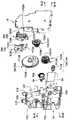
도 14 및 도 15는 각각 제1 상품 반출 장치(20a)에 있어서의 구동 유닛(40)의 주요부를 도시하는 것으로, 도 14는 우측 전방에서 본 경우를 도시하는 분해 사시도이고, 도 15는 좌측 후방에서 본 경우를 도시하는 분해 사시도이다.Figs. 14 and 15 show the main parts of the
구동 유닛(40)은 베이스(21)의 배면측 상부의 중앙 영역에 배치되어 있다. 이 구동 유닛(40)은 베이스(21)의 배면에 부착되는 유닛 베이스(41)를 구비하고 있다.The
유닛 베이스(41)는, 예컨대 수지재 등에 의해 형성되는 것으로, 후면이 개구된 상자형으로 형성된 것이다. 이러한 유닛 베이스(41)는, 수지제의 유닛 커버(42)가 부착됨으로써 후면의 개구가 폐색되어, 유닛 커버(42)와의 사이에 수용 공간을 형성하고 있다. 이와 같이 하여 유닛 베이스(41)와 유닛 커버(42)에 의해 형성되는 수용 공간에는, 모터(43), 기어 부재(44), 캐리어 스위치(45) 및 링크 레버(46)가 수납되어 있다.The
모터(43)는 구동원으로 되는 것으로, 후술하는 불출 제어부(60)로부터 주어지는 지령에 따라서 구동하는 정회전 및 역회전 가능한 직류 모터이다. 이 모터(43)는, 유닛 베이스(41)의 모터 유지부(41a)에 유지된 상태로 배치되어 있다.The
기어 부재(44)는, 웜 기어(441), 중간 기어(442) 및 출력 기어(출력 부재)(443)를 구비하여 구성되어 있다. 웜 기어(441)는 웜(441a)과 웜 휠(441b)을 갖고 있다.The
웜(441a)은 원통형의 형태를 이루며, 모터(43)의 출력축(43a)에 부착되어 있다. 웜 휠(441b)은, 원판형의 제1 웜 휠(441b1)과, 원판형의 제2 웜 휠(441b2)을 갖고 있다.The
제1 웜 휠(441b1)은 중심 부분에 후방으로 향해서 돌출되는 축형상부가 형성됨과 더불어 원통면에 복수의 이빨로 이루어지는 기어부가 형성되어 있다.The first worm wheel 441b1 is formed with a shaft portion that protrudes rearward in the center portion, and a gear portion formed of a plurality of teeth is formed on the cylindrical surface.
제2 웜 휠(441b2)은, 제1 웜 휠(441b1)의 앞면 측에 위치하고 있으며, 자신의 중심축이 제1 웜 휠(441b1)의 축형상부의 중심축과 일치하는 축형상부가 전방으로 향해서 돌출되는 양태로 형성되어 있다. 이 제 2 웜 휠(441b2)의 원통면에도 복수의 이빨로 이루어지는 기어부가 형성되어 있다.The second worm wheel 441b2 is located on the front side of the first worm wheel 441b1 and has a shaft portion whose center axis coincides with the central axis of the axial portion of the first worm wheel 441b1 toward the front As shown in Fig. The second worm wheel 441b2 has a cylindrical portion formed with a plurality of gear teeth.
이러한 웜 휠(441b)은, 제1 웜 휠(441b1)의 기어부가 웜(441a)에 맞물린 상태로 축형상부가 유닛 베이스(41) 및 유닛 커버(42)의 오목부(41b, 42b)에 삽입 관통함으로써, 축형상부의 중심축 둘레로 회전 가능하게 배치되어 있다.The
중간 기어(442)는, 원판형의 제1 중간 기어(442a)와, 원판형의 제2 중간 기어(442b)를 갖고 있다. 제1 중간 기어(442a)는 중심 부분에 후방으로 향해서 돌출되는 축형상부가 형성됨과 더불어 원통면에 복수의 이빨로 이루어지는 기어부가 형성되어 있다.The
제2 중간 기어(442b)는, 제1 중간 기어(442a)의 뒷면 측에 위치하고 있으며, 자신의 중심축이 제1 중간 기어(442a)의 축형상부의 중심축과 일치하는 축형상부가 전방으로 향해서 돌출되는 양태로 형성되어 있다. 이 제2 중간 기어(442b)의 원통면에도 복수의 이빨로 이루어지는 기어부가 형성되어 있다.The second
이러한 중간 기어(442)는, 제1 중간 기어(442a)의 기어부가 제2 웜 휠(441b2)의 기어부에 맞물린 상태로 축형상부가 유닛 베이스(41) 및 유닛 커버(42)의 오목부(41c, 42c)에 삽입 관통함으로써, 축형상부의 중심축 둘레로 회전 가능하게 배치되어 있다.The
출력 기어(443)는, 웜 휠(441b)이나 중간 기어(442)에 비해서 넓은 직경이 되는 원판형을 이루고 있다. 이 출력 기어(443)의 원통면에도 복수의 이빨로 이루어지는 기어부가 형성되어 있다. 또한, 출력 기어(443)의 중심 부분에는 전후 방향으로 향해서 돌출되는 축형상부가 형성되어 있다. 더욱이, 출력 기어(443)는, 앞면에 캠부(443a)가 형성되며, 또한 뒷면에 누름편(443b)이 형성되어 있다.The
캠부(443a)는, 원호형의 형태를 이루며, 전방으로 향해서 돌출되는 양태로 형성되어 있다. 이 캠부(443a)는, 그 원호형의 길이가 페달 링크(35)를 위쪽으로 향해서 이동시킨 후에 그 상태를 유지하기에 충분한 크기가 되도록 형성되어 있다.The
누름편(443b)은, 대략 V자형을 이루고 있고, 캠부(443a)와 반대쪽의 면이 되는 뒷면에 있어서 후방으로 향해서 돌출되는 양태로 형성되어 있다.The pushing
이러한 출력 기어(443)는, 기어부가 제2 중간 기어(442b)의 기어부에 맞물린 상태로 축형상부가 유닛 베이스(41) 및 유닛 커버(42)의 오목부(41d, 42d)에 삽입 관통함으로써, 축형상부의 중심축 둘레로 회전 가능하게 배치되어 있다.The
캐리어 스위치(45)는, 소위 푸시형 스위치이며, 접촉자(45a)를 갖추고 있다. 이 캐리어 스위치(45)는, 출력 기어(443)가 배치되는 영역보다도 약간 위쪽에 유지된 상태로 유닛 베이스(41)에 배치되어 있다. 이 캐리어 스위치(45)는, 접촉자(45a)가 눌리면 온 상태가 되어, 그 취지를 온 신호로서 불출 제어부(60)에 부여하는 것인 한편, 접촉자(45a)가 눌리지 않는 경우는 오프 상태가 되어, 그 취지를 오프 신호로서 불출 제어부(60)에 부여하는 것이다.The
링크 레버(46)는, 제1 링크 레버(461) 및 제2 링크 레버(462)를 구비하여 구성되어 있다. 제1 링크 레버(461)는, 예컨대 수지 재료로 형성되는 것으로, 기단부(461a)에 관통 구멍(461a1)이 형성되어 있다. 이 제1 링크 레버(461)는, 선단부(461b)가 기단부(461a)로부터 우측 비스듬히 아래쪽으로 연장된 후에 우측 비스듬히 위쪽으로 만곡된 후크 형상을 이루고 있다. 또한, 제1 링크 레버(461)의 기단부(461a)에는 걸림부(461c)가 마련되어 있다. 걸림부(461c)는, 기단부(461a)의 좌측 단부보다 아래쪽으로 향해서 연장되는 탄성 변형 가능한 판 형상의 탄성 부재이다.The
이러한 제1 링크 레버(461)는, 기단부(461a)의 관통 구멍(461a1)에 유닛 커버(42)에 설치된 제1 링크축(42e)이 삽입 관통함으로써 출력 기어(443)의 전방 측에 있어서 제1 링크축(42e)의 중심축 둘레로 회전할 수 있게 배치되어 있다. 이 경우, 제1 링크 레버(461)는, 유닛 베이스(41) 및 유닛 커버(42)에 의해 형성되는 우측 개구(도시하지 않음)를 관통하고 있으며, 선단부(461b)가 유닛 베이스(41) 및 유닛 커버(42)의 외부에 위치하고 있다. 그리고, 제1 링크 레버(461)는, 우측 개구의 좌측 가장자리부(471)에 걸림부(461c)가 맞닿음으로써 평상 상태에 있어서의 자세가 정해져 있다.The
제2 링크 레버(462)는, 예컨대 수지 재료로 형성되는 것으로, 기단부(462a)에 관통 구멍(462a1)이 형성되어 있다. 이 제2 링크 레버(462)는, 선단부(462b)가 기단부(462a)로부터 좌측 비스듬히 아래쪽으로 연장된 후에 좌측 비스듬히 위쪽으로 만곡된 후크 형상을 이루고 있다. 또한, 이 제2 링크 레버(462)의 선단부(462b)는, 제1 링크 레버(461)의 선단부(461b)보다도 전후 폭이 크게 되어 있다. 더욱이, 제2 링크 레버(462)의 기단부(462a)에는 걸림부(462c)가 마련되어 있다. 걸림부(462c)는, 기단부(462a)의 우측 단부보다 아래쪽으로 향해서 연장되는 탄성 변형 가능한 판 형상의 탄성 부재이다.The
이러한 제2 링크 레버(462)는, 기단부(462a)의 관통 구멍(462a1)에 유닛 커버(42)에 설치된 제2 링크축(42f)이 삽입 관통함으로써 출력 기어(443)의 전방 측에 있어서 제2 링크축(42f)의 중심축 둘레로 회전할 수 있게 배치되어 있다. 이 경우, 제2 링크 레버(462)는, 유닛 베이스(41) 및 유닛 커버(42)에 의해 형성되는 좌측 개구(도시하지 않음)를 관통하고 있으며, 선단부(462b)가 유닛 베이스(41) 및 유닛 커버(42)의 외부에 위치하고 있다. 그리고, 제2 링크 레버(462)는, 좌측 개구의 우측 가장자리부(472)에 걸림부(462c)가 맞닿음으로써 평상 상태에 있어서의 자세가 정해져 있다.The
도 16은 도 2~도 4에 도시한 제2 상품 반출 장치(20b)를 우측 전방에서 본 경우를 도시하는 사시도이다. 도 17은 도 2~도 4, 도 16에 도시한 제2 상품 반출 장치(20b)의 주요부를 우측에서 본 경우를 모식적으로 도시하는 설명도이다. 또한, 제2 상품 반출 장치(20b)는, 대부분의 구성 요소가 제1 상품 반출 장치(20a)의 구성 요소와 공통되어 있으며, 제1 상품 반출 장치(20a)의 구성 요소에 대하여 전후의 방향을 달리함으로써 좌우 방향이 반대가 되는 것이다. 따라서, 제2 상품 반출 장치(20b)를 설명함에 있어서는, 도시를 적절하게 생략하여, 제2 상품 반출 장치(20b)의 구성 요소 중 제1 상품 반출 장치(20a)의 구성 요소와 공통되는 것에는 제1 상품 반출 장치(20a)에서 붙인 부호에 「′」를 붙여 간단히 설명한다.Fig. 16 is a perspective view showing a case where the second
제2 상품 반출 장치(20b)는, 제2 상품 수납 통로(13b)에 적용되는 것으로, 이 제2 상품 수납 통로(13b)의 하부에 배치되어 있다. 이 제2 상품 반출 장치(20b)는, 대향하는 통로 폭 규정판(17)과의 사이에 있어서 상품의 거동을 제어함으로써, 반출 대기 상태에 있어서는 제2 상품 수납 통로(13b)에 상품을 수납하는 한편, 구동하는 경우에는 대응하는 상품을 하나씩 상품 슈터(5)에 반출하도록 기능하는 것으로, 베이스(21′)를 구비하고 있다.The second
베이스(21′)는, 도 18에 도시한 것과 같이, 강판에 절삭 가공 및 굴곡 가공을 실시하여 구성된 것으로, 자신의 표면을 통로 폭 규정판(17)에 대향시키는 양태로 배치되어 있다. 이 베이스(21′)는, 양측부가 굴곡됨으로써 측벽(21a′)이 형성되어 있는 한편, 중간부에 제1 삽통 구멍(22′) 및 제2 삽통 구멍(23′)이 형성되어 있다. 제1 삽통 구멍(22′) 및 제2 삽통 구멍(23′)의 주연부는 측벽(21a′)과 마찬가지로 굴곡되어 플랜지를 형성하고 있다.As shown in Fig. 18, the base 21 'is formed by subjecting a steel sheet to a cutting process and a bending process, and is disposed in such a manner that its surface is opposed to the passage
제1 삽통 구멍(22′)과 제2 삽통 구멍(23′)은 상호 좌우로 나란하게 형성되어 있으며 상하 치수가 동일한 크기를 갖고 있다. 이들 제1 삽통 구멍(22′)과 제2 삽통 구멍(23′)에서는, 제1 삽통 구멍(22′)이 제2 삽통 구멍(23′)의 우측에 위치하고 있고, 제1 삽통 구멍(22′)의 좌우 폭이 제2 삽통 구멍(23′)의 좌우 폭보다도 큰 것이다. 또한 제1 삽통 구멍(22′)과 제2 삽통 구멍(23′)은, 상호 전체적으로 대략 직사각형의 형태를 이루는 관통 개구[후술하는 하측 페달(28′) 및 상측 페달(29′)을 베이스(21′) 안으로 퇴행시키는 오목부]이며, 제1 삽통 구멍(22′)의 상단부가 우측으로 돌출되어 있고, 제2 삽통 구멍(23′)의 상단부가 좌측으로 돌출되어 있다. 제1 삽통 구멍(22′)의 우측 가장자리부에는 제1 우측 베어링편(22a′)이 마련되며 또한 제1 삽통 구멍(22′)의 좌측 가장자리부에는 제1 좌측 베어링편(22b′)이 마련되어 있고, 제2 삽통 구멍(23′)의 우측 가장자리부에는 제2 우측 베어링편(23a′)이 마련되며 또한 제2 삽통 구멍(23′)의 좌측 가장자리부에는 제2 좌측 베어링편(23b′)이 마련되어 있다. 이 때, 제1 좌측 베어링편(22b′) 및 제2 우측 베어링편(23a′)은, 제1 삽통 구멍(22′) 및 제2 삽통 구멍(23′)의 주연부에 형성한 플랜지에 상당하는 것이다. 또한, 제1 좌측 베어링편(22b′) 및 제2 우측 베어링편(23a′)은, 후술하는 베어링부(24′)를 끼워 맞춰 유지하는 곳의, 베이스(21′)에 일체로 형성됨과 더불어 횡단면 コ자형(불연속)으로 형성된 베어링 유지부에 있어서의 コ자형의 양 다리 부재를 이루는 축 삽통 플랜지에 형성되어 있는 것이다. 또한, 이 베어링 유지부는, 전체적으로 대략 직사각형의 형태를 이루는 제1 삽통 구멍(22′)과 제2 삽통 구멍(23′)으로 이루어지는 큰 관통 개구를 베이스(21′)에 형성한 경우에도 베이스(21′)의 강도를 유지하는 기능을 갖는다.The first through-hole 22 'and the second through-hole 23' are formed horizontally to each other and have the same vertical size. In the first through-hole 22 'and the second through-hole 23', the first through-hole 22 'is located on the right side of the second through-hole 23' Is larger than the left-right width of the second insertion hole 23 '. The first through-hole 22 'and the second through-hole 23' are formed to have a through-hole (a
이러한 구성을 갖는 베이스(21′)에는, 도 19에 도시한 것과 같은 베어링부(24′) 및 가이드(48)가 장착되어 있다. 베어링부(24′)는, 수지 재료 등에 의해 구성되는 것으로, 제1 좌측 베어링편(22b′)과 제2 우측 베어링편(23a′) 사이에 끼워져 있다. 가이드(48)는, 베어링부(24′)와 마찬가지로 수지 재료 등에 의해 구성되는 것으로, 제2 좌측 베어링편(23b′)에 인접하는 양태로 베이스(21′)에 끼워져 있다.A bearing portion 24 'and a
상기 베이스(21′)에는 제1 요동 지지축(28a′) 및 제2 요동 지지축(29a′)이 설치되어 있다. 제1 요동 지지축(28a′)은, 대략 수평 방향을 따라서 연장되는 양태로 제1 우측 베어링편(22a′), 제1 좌측 베어링편(22b′), 제2 우측 베어링편(23a′), 제2 좌측 베어링편(23b′) 및 베어링부(24′)에 형성된 각 관통 구멍(22a1′, 22b1′, 23a1′, 23b1′, 24a′)을 관통하여 가설된 축 형상 부재이며, 그 중간부에 하측 페달(28′)을 지승하고 있다.The base 21 'is provided with a first
또한 제1 요동 지지축(28a′)의 우측 단부에는 제2 매진 링크(50)가 배치되어 있다. 제2 매진 링크(50)는, 도시하지 않는 제2 매진 기초부 및 제2 매진 맞닿음부와, 제2 매진 누름부(53)(도 11 참조)를 구비하여 구성되어 있다. 제2 매진 기초부는, 예컨대 2개의 C자형을 이루는 원판형 부위의 하단부끼리를 연결부로 연결함으로써 형성되어 있고, 각 원판형 부위에 제1 요동 지지축(28a′)의 우측 단부를 관통시키는 관통 구멍이 형성되어 있다. 제2 매진 맞닿음부는, 제2 매진 기초부 중 좌측의 원판형 부위의 전방 부분보다 좌측으로 향해서 연장되어 있다. 이 제2 매진 맞닿음부는, 제1 매진 링크(30)를 구성하는 제1 매진 맞닿음부(32)보다도 좌측에 마련되어 있으며, 상호 간섭하지 않게 되어 있다. 제2 매진 누름부(53)는, 제2 매진 기초부의 우측의 원판형 부위의 하측 부분보다 우측으로 향해서 돌출되도록 형성되어 있다. 제2 매진 기초부에 형성한 관통 구멍은, 제1 요동 지지축(28a′)보다도 크게 형성되어, 제2 매진 링크(50)가 제1 요동 지지축(28a′) 에 대하여 자유롭게 움직일 수 있게 구성되어 있다.A
제2 요동 지지축(29a′)은, 제1 요동 지지축(28a′)보다도 위쪽 영역에 있어서, 대략 수평 방향을 따라서 연장되는 양태로 제1 우측 베어링편(22a′), 제1 좌측 베어링편(22b′), 제2 우측 베어링편(23a′), 제2 좌측 베어링편(23b′) 및 베어링부(24′)에 형성된 각 관통 구멍(22a2′, 22b2′, 23a2′, 23b2′, 24b′)을 관통하여 가설된 축 형상 부재이며, 그 중간부에 상측 페달(29′)을 지승하고 있다.The second
하측 페달(28′)은, 플레이트형 부재이며, 기단부에 제1 요동 지지축(28a′)을 삽입 관통시킴으로써 이 제1 요동 지지축(28a′) 의 중심축 둘레로 요동 가능하게 되는 양태로 배치되어 있다.The
하측 페달(28′)의 선단부는, 제1 요동 지지축(28a′)의 직경 바깥 방향으로 향해서 연장되어 있으며, 제1 요동 지지축(28a′) 의 중심축 둘레로 요동한 경우에 제1 삽통 구멍(22′) 및 제2 삽통 구멍(23′)을 통하여 제2 상품 수납 통로(13b)로 진퇴 이동할 수 있다. 즉, 하측 페달(28′)은, 제2 상품 수납 통로(13b)에 대하여 진퇴 이동하는 양태로 요동 가능하게 배치되어 있다.The distal end of the
하측 페달(28′)과 베이스(21′) 사이에는 하측 페달 스프링(28b′)이 개재되어 있다. 하측 페달 스프링(28b′)은, 제2 상품 수납 통로(13b)에 대하여 하측 페달(28′)을 진출 이동하는 방향으로 향해서 항상 압박하는 것이다. 보다 상세히 설명하면, 하측 페달 스프링(28b′)은, 도 17에 도시한 것과 같이 하측 페달(28′)의 선단부가 제1 요동 지지축(28a′)보다도 위쪽에 위치하도록 하측 페달(28′)을 대기 자세[이하, 상품 없음 대기 자세(제2 대기 자세)라고도 함]로 하게 하는 것이다. 그리고, 하측 페달 스프링(28b′)은, 하측 페달(28′)의 상면에 상품이 놓이는 경우에는, 하측 페달(28′)의 선단부가 제1 요동 지지축(28a′)과 동등한 높이 레벨에 위치하도록 하측 페달(28′)을 대기 자세[이하, 상품 있음 대기 자세(제1 대기 자세)라고도 함]로 하게 하는 것이다.A
이에 따라, 하측 페달(28′)은, 상품 없음 대기 자세가 되는 경우에는, 상품 있음 대기 자세가 될 때보다도 선단부가 위쪽에 위치하게 된다.Accordingly, when the
그리고, 하측 페달(28′)이 상품 없음 대기 자세가 되는 경우, 도 11에 도시한 것과 같이, 하측 페달(28′)의 기단부가 제2 매진 링크(50)의 제2 매진 맞닿음부에 맞닿는 결과, 제2 매진 링크(50)는, 제1 요동 지지축(28a′)을 축심으로 하여 회전하고, 이에 따라 제2 매진 누름부(53)가 제2 매진 검지 스위치(27)의 접촉자(27a)를 누른다. 이에 따라, 제2 매진 검지 스위치(27)에서는, 접촉자(27a)가 눌려 스프링의 압박력에 대항하여 후방으로 변위함으로써 온 상태가 되어, 온 신호를 불출 제어부(60)에 송출하게 된다.11, the proximal end of the
그 한편, 하측 페달(28′)이 상품 있음 대기 자세가 되는 경우, 하측 페달(28′)의 기단부가 제2 매진 링크(50)의 제2 매진 맞닿음부로부터 격리되는 결과, 제2 매진 링크(50)는 자유로운 상태가 된다. 이에 따라, 제2 매진 검지 스위치(27)에서는, 접촉자(27a)가 스프링에 압박됨으로써 기립한 자세가 됨으로써 오프 상태가 되어, 오프 신호를 불출 제어부(60)에 송출하게 된다. 즉, 자유로운 상태가 된 제2 매진 링크(50)는, 제2 매진 누름부(53)가 접촉자(27a)에 눌림으로써 제1 요동 지지축(28a′)을 축심으로 하여 회전하게 된다.On the other hand, when the
상기 하측 페달(28′)은, 판 형상의 페달 본체부(281′)와, 한 쌍의 안내부(282′)를 구비하고 있다. 한 쌍의 안내부(282′)는, 상기 페달 본체부(281′)의 배면 측에 설치되어 있다. 각 안내부(282′)는, 상하 방향을 따라서 연장되는 판 형상 부재이며, 상호 대향하게 형성되어 있다. 각 안내부(282′)의 상호 대향하는 대향면에는 도시하지 않는 안내 홈이 형성되어 있다.The
안내 홈은, 하측 페달(28′)을 제2 상품 수납 통로(13b)에 대하여 최대로 진출 이동시킨 진출 위치에 배치한 상태에 있어서, 가장 아래쪽에 위치하며 또한 후술하는 회동 스토퍼(36′)의 페달 조작축(361′)(도 4 참조)이 끼워져 들어가는 끼워맞춤부와, 하측 페달(28′)을 제2 상품 수납 통로(13b)에 대하여 최대로 퇴행 이동시킨 퇴행 위치에 배치한 상태에 있어서, 가장 위쪽에 위치하며 또한 회동 스토퍼(36′)의 페달 조작축(361′)이 맞닿는 맞닿음부와, 이들 끼워맞춤부 및 맞닿음부가 연속되도록 접속하는 제1 안내부 및 제2 안내부를 구비하고 있다.The guide groove is located at the lowest position in the state in which the
제1 안내부는, 하측 페달(28′)을 제2 상품 수납 통로(13b)에 대하여 최대로 진출 이동시킨 위치(진출 위치)에 배치한 상태에 있어서, 끼워맞춤부로부터 베이스(21′) 에 대하여 격리되도록 비스듬히 위쪽으로 경사진 후, 베이스(21′) 에 대하여 근접하도록 비스듬히 위쪽으로 경사져 맞닿음부에 이르는 양태로 안내부(282′)에 형성되어 있다.The first guide portion is located at a position (advanced position) where the
제2 안내부는, 하측 페달(28′)을 제2 상품 수납 통로(13b)에 대하여 최대로 진출 이동시킨 위치(진출 위치)에 배치한 상태에 있어서, 맞닿음부로부터 베이스(21′) 에 대하여 격리되도록 비스듬히 아래쪽으로 경사져 끼워맞춤부에 이르는 양태로 안내부(282′)에 형성되어 있다.The second guide portion is disposed at a position (advanced position) where the
이러한 하측 페달(28′)의 제1 요동 지지축(28a′)으로부터의 직경 바깥 방향의 길이는, 제2 상품 수납 통로(13b)에 대하여 최대로 진출 이동한 위치(진출 위치)에 위치하는 경우에, 통로 폭 규정판(17)과의 사이에 최대 폭이 작은 상품의 최대 폭보다도 작은 간극을 확보할 수 있는 길이로 설정되어 있다.The length of the
상측 페달(29′)은, 플레이트형 부재이며, 기단부에 제2 요동 지지축(29a′)을 삽입 관통시킴으로써 이 제2 요동 지지축(29a′) 의 중심축 둘레로 요동할 수 있게 되는 양태로 베이스(21′)에 배치되어 있다.The upper pedal 29 'is a plate-like member and can swing about the central axis of the second
상측 페달(29′)의 선단부는, 제2 요동 지지축(29a′)의 직경 바깥 방향으로 향해서 연장되어 있으며, 제2 요동 지지축(29a′) 의 중심축 둘레로 요동한 경우에 제1 삽통 구멍(22′) 및 제2 삽통 구멍(23′)을 통하여 제2 상품 수납 통로(13b)로 진퇴 이동하는 것이 가능하다. 즉, 상측 페달(29′)은, 제2 상품 수납 통로(13b)에 대하여 진퇴 이동하는 양태로 요동 가능하게 배치되어 있다.The distal end portion of the upper pedal 29 'extends toward the outside of the diameter of the second
상측 페달(29′)과 베이스(21′) 사이에는 상측 페달 스프링(도시하지 않음)이 개재되어 있다. 상측 페달 스프링은, 제2 상품 수납 통로(13b)에 대하여 상측 페달(29′)이 퇴행 이동하는 방향으로 향해서 항상 압박하는 것이다.An upper pedal spring (not shown) is interposed between the upper pedal 29 'and the base 21'. The upper pedal spring always urges the second
상기 상측 페달(29′)에는, 누름 경사면(291′), 오목부(292′), 스토퍼 맞닿음부(293′) 및 돌기부(294′)가 마련되어 있다. 누름 경사면(291′)은, 상측 페달(29′)의 선단 부분에 형성되어 있으며, 상측 페달(29′)을 제2 상품 수납 통로(13b)에 대하여 퇴행 이동시킨 경우에는, 제2 상품 수납 통로(13b)로 향해서 점차 낮아지는 양태로 형성된 만곡형의 경사면이다. 오목부(292′)는, 상측 페달(29′)의 배면 측에 형성되어 있고, 상측 페달(29′)의 양 측면에 개구되는 양태로 형성한 대략 수평 방향을 따라서 연장되는 한 줄의 오목부이다. 스토퍼 맞닿음부(293′)는, 후술하는 스토퍼 핀이 맞닿는 부위이며, 상측 페달(29′)의 배면에 있어서 오목부(292′)의 위쪽으로 경사지는 양태로 형성되어 있다.The upper pedal 29 'is provided with a pressing slope 291', a
돌기부(294′)는, 상측 페달(29′)의 기단부에 있어서 제2 상품 수납 통로(13b)로 향해서 돌출된 양태로 형성되어 있다.The protruding portion 294 'is formed so as to protrude toward the second
이 상측 페달(29′)은, 상기 상측 페달 스프링의 압박력에 의해서 제2 상품 수납 통로(13b)로 퇴행 이동하도록 압박되고 있는데, 상기 오목부(292′)에 스토퍼 핀이 맞닿음으로써 제2 상품 수납 통로(13b)에 대하여 퇴행 이동한 상태로 초기 위치가 설정되어 있다.The upper pedal 29 'is urged to retreat to the second
이러한 상측 페달(29′)은, 제2 상품 수납 통로(13b)에 대하여 최대로 진출 이동한 위치(진출 위치)에 위치하는 상태에 있어서, 제2 요동 지지축(29a′)을 통과하는 수직면에 대하여 앞으로 기운 상태에 있다. 그리고 상측 페달(29′)의 제2 요동 지지축(29a′)으로부터의 직경 바깥 방향의 길이는, 상술한 앞으로 기운 상태에 있어서, 통로 폭 규정판(17)과의 사이에 최대 폭이 작은 상품의 최대 폭보다도 작은 간극을 확보할 수 있는 길이로 설정되어 있다.The upper pedal 29 'is located on the vertical plane passing through the second
상기 베이스(21′)에 있어서는, 베어링부(24′)와 제2 좌측 베어링편(23b′)의 사이에는 스토퍼 핀(도시하지 않음), 페달 스토퍼 핀(34b′) 및 스토퍼축(34c′)이 가설되어 있다.In the base 21 ', a stopper pin (not shown), a
스토퍼 핀은, 베어링부(24′)와 제2 좌측 베어링편(23b′) 사이에 대략 수평 방향을 따라서 배치된 축 형상 부재이다. 이 스토퍼 핀은, 페달 링크(35′)에 결합되어 있으며, 상기 페달 링크(35′)의 상하 방향으로의 이동에 따라 상하 방향을 따르는 이동이 가능하다. 또한, 스토퍼 핀은, 초기 위치에 있는 상측 페달(29′)의 오목부(292′)에 맞닿고 있다.The stopper pin is a shaft member disposed between the bearing portion 24 'and the second
페달 스토퍼 핀(34b′)은, 베어링부(24′)와 제2 좌측 베어링편(23b′) 사이에 대략 수평 방향을 따라서 배치된 축 형상 부재이다. 이 페달 스토퍼 핀(34b′)은, 페달 링크(35′)에 결합되어 있으며, 상기 페달 링크(35′)의 상하 방향으로의 이동에 따라 상하 방향을 따르는 이동이 가능하다.The
스토퍼축(34c′)은, 베어링부(24′)와 제2 좌측 베어링편(23b′) 사이에 대략 수평 방향을 따라서 배치된 축 형상 부재이며, 그 중간부에 회동 스토퍼(36′)를 지승하고 있다.The
회동 스토퍼(36′)는, 기단부의 삽통 구멍에 스토퍼축(34c′)을 삽입 관통시키며 또한 이 스토퍼축(34c′) 의 중심축 둘레로 요동 가능하게 되는 양태로 베어링부(24′)와 제2 좌측 베어링편(23b′) 사이에 배치되어 있다.The stopper 36 'includes a bearing portion 24' and a
회동 스토퍼(36′)의 선단부는, 스토퍼축(34c′)의 직경 바깥 방향으로 향해서 연장되어 있으며, 스토퍼축(34c′) 의 중심축 둘레로 요동한 경우에 제2 삽통 구멍(23′)을 통하여 제2 상품 수납 통로(13b)로 진퇴 이동할 수 있다.The distal end portion of the rotation stopper 36 'extends toward the outside of the diameter of the
이 회동 스토퍼(36′)는, 선단부의 관통 구멍(도시하지 않음)을 페달 조작축(361′)(도 4 참조)이 관통함으로써 상기 페달 조작축(361′)을 갖고 있다. 페달 조작축(361′)은, 대략 수평 방향을 따라서 배치된 축 형상 부재이며, 그 양단부가 상기 하측 페달(28′)의 안내 홈에 끼워져 들어가 있다.The pivotal movement stopper 36 'has the pedal operation shaft 361' through a pedal operation shaft 361 '(see FIG. 4) through a through hole (not shown) at the distal end. The pedal operation shaft 361 'is a shaft-like member disposed along the substantially horizontal direction, and both ends thereof are inserted into the guide grooves of the
상기 회동 스토퍼(36′)와 베이스(21′) 사이에는 페달 조작 스프링(도시하지 않음)이 개재되어 있다. 페달 조작 스프링은, 제2 상품 수납 통로(13b)에 대하여 회동 스토퍼(36′)를 진출 이동시키는 방향으로 향해서 항상 압박하는 것이다.A pedal operation spring (not shown) is interposed between the pivotal stopper 36 'and the base 21'. The pedal operation spring always urges the pivotal movement stopper 36 'toward the advancing movement with respect to the second
이러한 회동 스토퍼(36′)는, 페달 조작 스프링에 의해서 제2 상품 수납 통로(13b)에 대하여 진출 이동하는 방향으로 향해서 압박되고, 상기 회동 스토퍼(36′)의 오목부(36b′)에 페달 스토퍼 핀(34b′)이 진입하여 이 페달 스토퍼 핀(34b′)에 맞닿음으로써 퇴행 이동하는 방향으로의 이동이 규제되고 있으며, 제2 상품 수납 통로(13b)에 대하여 진출 이동한 상태에서의 초기 위치가 설정되어 있다. 또한, 하측 페달(28′)이 하측 페달 스프링(28b′)에 압박되고 있기 때문에, 회동 스토퍼(36′)는, 페달 조작축(361′)의 양끝이 안내 홈의 끼워맞춤부에 위치하고 있으며, 하측 페달(28′)이 제2 상품 수납 통로(13b)에 대하여 진출 이동한 위치에 초기 위치가 설정되어 있다.The pivotal stopper 36 'is urged by the pedal operation spring toward the second
상기 페달 링크(35′)는, 상하 방향을 따라서 연장되는 긴 판 형상 부재이며, 상부가 후방으로 향해서 굴곡된 후에 위쪽으로 향해서 연장되어 있다. 이 페달 링크(35′)의 상부에는, 전방으로 향해서 연장된 후에 비스듬히 위쪽으로 향해서 연장되는 맞닿음편(351′)이 마련됨과 더불어, 링크 스프링(35a′)을 걸어 고정하는 걸림부(352′)가 마련되어 있다. 이 링크 스프링(35a′)은, 페달 링크(35′)와 베이스(21′) 사이에 개재하는 것으로, 페달 링크(35′)를 아래쪽으로 향해서 항상 압박하는 것이다.The pedal link 35 'is a long plate-shaped member extending along the vertical direction, and the upper portion thereof is bent backward and then extends upward. At the upper portion of the pedal link 35 ', there is provided a contact piece 351' which extends forward and then extends obliquely upward, and a latching
페달 링크(35′)가 링크 스프링(35a′)에 의해서 압박되어 아래쪽으로 배치된 상태에서는, 스토퍼 핀에 퇴행 위치에 배치된 상측 페달(29′)의 오목부(292′)가 맞닿고 있다. 게다가 페달 스토퍼 핀(34b′)에 진출 위치에 배치된 회동 스토퍼(36′)가 맞닿고 있어, 회동 스토퍼(36′)의 퇴행 이동이 규제되고 있다. 또한, 진출 위치에 배치된 회동 스토퍼(36′)의 페달 조작축(361′)은 상기 하측 페달(28′)의 끼워맞춤부에 끼워져 들어가 있으며, 이에 따라 진출 위치에 배치된 하측 페달(28′)의 퇴행 이동이 규제되고 있다.In the state where the pedal link 35 'is pushed down by the
이에 대하여 링크 스프링(35a′)의 압박력에 대항하여 페달 링크(35′)가 위쪽에 배치된 상태에서는, 스토퍼 핀에 상측 페달(29′)의 스토퍼 맞닿음부(293′)가 맞닿음으로써, 상측 페달(29′)의 퇴행 이동이 규제되고, 상측 페달 스프링의 압박력에 대항하여 상측 페달(29′)이 진출 이동하여 진출 위치에 배치된다.In contrast, when the pedal link 35 'is disposed above the
한편, 회동 스토퍼(36′)는, 페달 스토퍼 핀(34b′) 에 의한 퇴행 이동의 규제가 해제되기 때문에, 스토퍼축(34c′)을 중심으로 하여 퇴행 이동의 규제가 해제된다. 여기서, 회동 스토퍼(36′)에는 이 회동 스토퍼(36′)에 의해서 진출 위치에 유지되어 있는 하측 페달(28′)에 맞닿은 상품의 하중이 걸리고 있고, 회동 스토퍼(36′)가 퇴행 이동의 규제가 해제됨으로써 회동 스토퍼(36′)는 퇴행 이동을 시작한다. 회동 스토퍼(36′)의 퇴행 이동이 시작되면 페달 조작축(361′)이 하측 페달(28′)의 끼워맞춤부에서 벗어나기 때문에, 하측 페달(28′)은 제1 요동 지지축(28a′)을 중심으로 하여 퇴행 이동이 허용되어 상품의 하중에 의해서 하측 페달 스프링(28b′)의 탄성 압박력에 대항하여 퇴행 이동하게 된다.On the other hand, since the restriction of the detent movement by the
그리고, 이와 같이 하측 페달(28′)이 퇴행 이동하는 경우, 하측 페달(28′)의 기단부가 제2 매진 링크(50)의 제2 매진 맞닿음부로부터 격리되는 결과, 제2 매진 링크(50)는 자유로운 상태가 된다. 이에 따라, 제2 매진 검지 스위치(27)에서는, 접촉자(27a)가 스프링에 압박되어 기립한 자세가 됨으로써 오프 상태를 유지한다. 즉, 하측 페달(28′)이 퇴행 이동하는 경우도 상품 있음 대기 자세와 마찬가지로, 제2 매진 링크(50)가 제2 매진 검지 스위치(27)의 접촉자(27a)를 누르지 않는다.When the
이상과 같은 구성을 갖는 제1 상품 반출 장치(20a)와 제2 상품 반출 장치(20b)를, 하네스 가이드(25)를 가이드 부재로 하여 상호 등을 맞대고 결합되게 함으로써 상품 불출 장치(20)가 구성된다. 그리고, 이 경우에 있어서, 구동 유닛(40)을 구성하는 제1 링크 레버(461)는, 선단부가 페달 링크(35)의 맞닿음편(351)의 아래쪽 영역에 위치하고 있고, 제2 링크 레버(462)는, 선단부가 페달 링크(35′)의 맞닿음편(351′)의 아래쪽 영역에 위치하고 있다.The first
도 20은 상기 상품 불출 장치(20)의 특징적인 제어계를 도시하는 블록도이다. 이 도 20에 도시한 것과 같이, 상품 불출 장치(20)는 불출 제어부(60)를 구비하고 있다. 불출 제어부(60)는, 메모리(61)에 기억된 프로그램이나 데이터에 따라서 상품 불출 장치(20)의 동작을 통괄적으로 제어하는 것으로, 자동판매기의 판매 동작을 통괄하는 자판기 제어부(100)와 통신 가능한 것이다. 이 불출 제어부(60)가 실시하는 처리에 관해서는 후술한다.20 is a block diagram showing a characteristic control system of the
이상과 같이 구성한 상품 불출 장치(20)에서는, 대기 상태에서는 다음과 같이 된다. 한편, 이하에서는, 제1 상품 수납 통로(13a)에 수납된 상품을「제1 상품」이라고도 부르고, 제2 상품 수납 통로(13b)에 수납된 상품을 「제2 상품」이라고도 부르면서 설명한다.In the
제1 상품 반출 장치(20a)에 설치된 구동 유닛(40)에서는, 출력 기어(443)의 캠부(443a) 및 누름편(443b)이 가장 위쪽에 위치하고 있고, 누름편(443b)이 캐리어 스위치(45)의 접촉자(45a)를 누르고 있다. 이 경우, 캐리어 스위치(45)는 온 상태가 된다. 이러한 대기 상태에서는, 구동 유닛(40)을 구성하는 제1 링크 레버(461)의 선단부(461b)가 페달 링크(35)의 맞닿음편(351)으로부터 아래쪽으로 격리된 위치에 있고, 제2 링크 레버(462)의 선단부(462b)가 페달 링크(35′)의 맞닿음편(351′)으로부터 아래쪽으로 격리된 위치에 있다.The
그 때문에 제1 상품 반출 장치(20a)에서는, 도 5에 도시한 것과 같이, 페달 링크(35)가 아래쪽으로 배치된 상태에 있다. 또한, 제1 상품 수납 통로(13a)에 투입된 상품에 의해 하측 페달(28)의 상면에 상품이 놓임으로써 하측 페달(28)이 상품 있음 대기 자세로 되어 있으며 또한 상측 페달(29)이 제1 상품 수납 통로(13a)로부터 퇴행 이동한 자세로 되어 있다[도 23의 (a) 참조]. 이와 같이 하측 페달(28)이 상품 있음 대기 자세이기 때문에, 제1 매진 검지 스위치(26)는 접촉자(26a)가 기립한 자세가 되어 오프 상태로 되어 있다.Therefore, the first product carry-out
또한, 제2 상품 반출 장치(20b)에서는, 페달 링크(35′)가 아래쪽에 배치된 상태로 있고, 하측 페달(28′)이 상품 있음 대기 자세로 되어 있으며 또한 상측 페달(29′)이 제2 상품 수납 통로(13b)로부터 퇴행 이동한 자세로 되어 있다[도 24의 (a) 참조]. 이와 같이 하측 페달(28′)이 상품 있음 대기 자세이기 때문에, 제2 매진 검지 스위치(27)는 접촉자(27a)가 기립한 자세가 되어 오프 상태로 되어 있다.In the second product carry-out
이러한 상품 불출 장치(20)에서는, 불출 제어부(60)가 자판기 제어부(100)로부터 주어진 제1 상품의 반출 지령을 입력 처리한 경우에는 모터(43)를 정회전 구동시킨다.In this
이와 같이 모터(43)를 정회전 구동시키면, 웜 기어(441) 및 중간 기어(442)를 통해 모터(43)의 구동력을 전달받은 출력 기어(443)는, 전방에서 봤을 때 시계 방향으로 회전한다.When the
출력 기어(443)가 전방에서 봤을 때 시계 방향으로 회전하면, 출력 기어(443)의 누름편(443b)이 캐리어 스위치(45)의 접촉자(45a)로부터 이탈한다. 이에 따라, 캐리어 스위치(45)의 접촉자(45a)는 눌린 상태에서 개방되어 온 상태에서 오프 상태로 전환되고, 오프 신호를 불출 제어부(60)에 부여한다.The pushing
출력 기어(443)의 회전에 의해 캠부(443a)가, 제1 링크 레버(461)의 기단부(461a)에 위쪽으로부터 맞닿으면, 제1 링크 레버(461)는, 전방에서 봤을 때 반시계 방향으로 회전한다. 이 제1 링크 레버(461)가 반시계 방향으로 회전하면, 선단부(461b)가 위쪽으로 향해서 이동하게 된다. 이와 같이 하여 선단부(461b)가 위쪽으로 향해서 이동함으로써, 도 21 및 도 22에 도시한 것과 같이, 페달 링크(35)의 맞닿음편(351)에 맞닿아, 링크 스프링(35a)의 압박력에 대항하여 페달 링크(35)를 위쪽으로 향해서 소정 거리만큼 이동시킬 수 있으며, 더구나 캠부(443a)가 기단부(461a)에 미끄럼 접촉하고 있는 동안에는, 페달 링크(35)를 소정 거리만큼 위쪽으로 이동시킨 상태를 유지할 수 있다.When the
이 경우에 있어서, 제1 링크 레버(461)는, 캠부(443a)와 미끄럼 접촉하는 경우, 상기 캠부(443a)와 미끄럼 접촉 부분을 포함하는 면("가")이 자신의 중심축[제1 링크축(42e)의 중심축]과 출력 기어(443)의 중심축을 포함하는 평면("나")에 대하여 대략 직교하도록 조정된다.In this case, when the
이 페달 링크(35)의 위쪽으로의 이동에 따라, 스토퍼 핀(34a)은 스토퍼 핀 삽통 구멍(23b3, 24c1)의 하단부에서 위쪽으로 이동함과 더불어, 페달 스토퍼 핀(34b)은 페달 스토퍼 핀 지지 홈(23b4, 24c2)의 하단부에서 위쪽으로 이동한다.As the
이 때 스토퍼 핀(34a)이 상측 페달(29)의 오목부(292)의 가장자리 벽에 맞닿으면서 위쪽으로 이동하기 때문에, 도 23의 (b)에 도시한 것과 같이, 상측 페달(29)은 상측 페달 스프링의 압박력에 대항하여 초기 위치에서 진출 이동한다. 이 상측 페달(29)의 진출 이동은, 스토퍼 핀(34a)의 위쪽으로의 이동에 의해 이루어진다. 그리고, 스토퍼 핀(34a)이 스토퍼 핀 삽통 구멍(23b3, 24c1)의 상단부에 도달한 시점에서 스토퍼 맞닿음부(293)에 맞닿아 상측 페달(29)의 퇴행을 규제한다.At this time, since the
그리고, 진출 이동한 상측 페달(29)은, 최하위에서 2번째의 제1 상품(이하, 다음 상품이라고도 함)에 맞닿아, 다음 상품이 아래쪽으로 향해서 이동하는 것을 규제한다.Then, the
한편, 회동 스토퍼(36)는, 진출 위치에 유지되고 있는 하측 페달(28)에 맞닿은 상품의 하중이 걸리고 있기 때문에, 상기 페달 스토퍼 핀(34b)의 위쪽으로의 이동에 의해 퇴행 이동의 규제가 해제됨으로써 회동 스토퍼(36)는 퇴행 이동을 시작한다.On the other hand, since the
이와 같이 회동 스토퍼(36)가 퇴행 이동을 시작하면, 페달 조작축(361)이 끼워맞춤부(283a)로부터 빠져나가, 상품 자체의 중량에 의해서 하측 페달 스프링(28b)의 압박력에 대항하여 하측 페달(28)이 퇴행 이동을 시작한다. 끼워맞춤부(283a)로부터 빠져나온 회동 스토퍼(36)의 페달 조작축(361)은, 제1 안내부(283b)를 따라, 제1 안내부(283b)와 제2 안내부(283c)가 교차하는 위치로 향해서 이동한다.When the
이후, 도 23의 (c)에 도시한 것과 같이, 최하위 상품 자체의 중량에 의해 하측 페달(28)이 퇴행 이동하고, 최하위 상품의 아래쪽으로의 이동이 허용되어, 최하위 상품은 아래쪽으로 반출된다(도 8 참조). 반출된 상품은, 상품 슈터(5)를 통하여 상품 반출구(3c)에 안내되고, 또한 상품 추출구(2a)를 통해 빼낼 수 있는 상태가 된다.Thereafter, as shown in Fig. 23C, the
여기서, 최하위 상품이 하측 페달(28)을 빠져나오면, 하측 페달(28)은 하측 페달 스프링(28b)의 탄성 압박력에 의해서 진출 위치로 향하여 이동함과 더불어, 회동 스토퍼(36)도 페달 조작 스프링의 탄성 압박력에 의해서 진출 위치로 향하여 이동한다. 하측 페달(28) 및 회동 스토퍼(36)가 진출 위치로 향하여 이동하면, 제1 안내부(283b)와 제2 안내부(283c)가 교차하는 위치에 유지되어 있던 페달 조작축(361)이 끼워맞춤부(283a)로 향해서 제2 안내부(283c)를 따라서 이동하여, 하측 페달(28) 및 회동 스토퍼(36)가 진출 위치로 복귀한다.Here, when the lowermost article comes out of the
이 사이, 페달 링크(35)가 위쪽으로 이동하여, 스토퍼 핀(34a)이 스토퍼 핀 삽통 구멍(23b3, 24c1)의 상단부에 위치하며 또한 페달 스토퍼 핀(34b)이 페달 스토퍼 핀 지지 홈(23b4, 24c2)의 상단부에 위치하게 된다.The
그 후, 출력 기어(443)의 회전에 의해 캠부(443a)와 기단부(462a)의 맞닿음이 해제되면, 링크 스프링(35a)에 페달 링크(35)는 압박되어 아래쪽으로 이동한다.Thereafter, when the abutment of the
이 페달 링크(35)의 아래쪽으로의 이동에 의해, 스토퍼 핀(34a)은 스토퍼 핀 삽통 구멍(23b3, 24c1)의 상단부에서 아래쪽으로 이동함과 더불어, 페달 스토퍼 핀(34b)은 페달 스토퍼 핀 지지 홈(23b4, 24c2)의 상단부에서 아래쪽으로 이동한다.The
페달 스토퍼 핀(34b)이 페달 스토퍼 핀 지지 홈(23b4, 24c2)의 하단으로 이동하면 진출 위치로 복귀한 회동 스토퍼(36)의 배면 측의 오목부(36b)에 페달 스토퍼 핀(34b)이 맞닿는다. 이에 따라 퇴행 이동하는 방향으로의 이동이 규제되어, 도 23의 (d)에 도시한 것과 같이, 하측 페달(28)은 하측 페달 스프링(28b)의 압박력에 의해 제1 상품 수납 통로(13a)에 대하여 진출 이동한 상품 없음 대기 자세로까지 복귀한다. 이 결과, 제1 매진 검지 스위치(26)가 오프 상태에서 온 상태로 전환되어, 온 신호를 불출 제어부(60)에 부여한다.When the
한편, 상측 페달(29)은, 상측 페달 스프링에 압박되어, 스토퍼 핀(34a)의 아래쪽으로의 이동에 따라 퇴행 이동한다. 이에 따라 다음 상품의 아래쪽으로의 이동이 허용되고, 그 후 상기 다음 상품은 진출 이동한 하측 페달(28)에 맞닿아 아래쪽으로의 이동이 규제되는 한편, 도 23의 (a)에 도시한 것과 같이 하측 페달(28)은 상품 있음 대기 자세로 이행하여 대기 상태로 되돌아간다.On the other hand, the
구동 유닛(40)에서는, 출력 기어(443)의 전방에서 봤을 때 시계 방향을 따른 회전에 의해, 그 후에 캠부(443a)가 제2 링크 레버(462)의 기단부(462a)에 맞닿게 된다. 이 경우, 제2 링크 레버(462)는, 걸림부(462c)가 좌측 개구의 우측 가장자리부(472)에 맞닿아 있음으로써, 중심축 둘레의 회전이 규제되고 있다. 그 때문에, 기단부(462a)가 걸림부(462c)에 근접하는 것을 허용하도록 걸림부(462c)는 탄성 변형하여, 출력 기어(443)의 회전에 의한 캠부(443a)의 이동을 저해하지 않는다.The
그리고, 그 후에 출력 기어(443)의 회전에 의해 캠부(443a)가 대기 위치로 되돌아가면, 누름편(443b)이 캐리어 스위치(45)의 접촉자(45a)를 눌러 캐리어 스위치(45)가 오프 상태에서 온 상태로 전환되어, 온 신호를 불출 제어부(60)에 부여하게 된다. 또한, 누름편(443b)이 캐리어 스위치(45)의 접촉자(45a)를 누른 직후에 캠부(443a)가 제2 링크 레버(462)의 기단부(462a)에서 벗어나 제2 링크 레버(462)는 걸림부(462c)에 의해 원래의 상태로 복귀한다. 그 후, 불출 제어부(60)가 모터(43)를 구동 정지로 하게 한다.When the
한편, 상기 상품 불출 장치(20)에서는, 불출 제어부(60)가 자판기 제어부(100)로부터 주어진 제2 상품의 반출 지령을 입력 처리한 경우에는 모터(43)를 역회전 구동시킨다.On the other hand, in the
이와 같이 모터(43)를 역회전 구동시키면, 웜 기어(441) 및 중간 기어(442)를 통해 모터(43)의 구동력을 전달받은 출력 기어(443)는, 전방에서 봤을 때 반시계 방향으로 회전한다.When the
출력 기어(443)가 전방에서 봤을 때 반시계 방향으로 회전하면, 출력 기어(443)의 누름편(443b)이 캐리어 스위치(45)의 접촉자(45a)로부터 이탈한다. 이에 따라, 캐리어 스위치(45)의 접촉자(45a)는 눌린 상태에서 개방되어 온 상태에서 오프 상태로 전환되어, 오프 신호를 불출 제어부(60)에 부여한다.When the
출력 기어(443)의 회전에 의해 캠부(443a)가, 제2 링크 레버(462)의 기단부(462a)에 위쪽에서 맞닿으면, 제2 링크 레버(462)는, 전방에서 봤을 때 시계 방향으로 회전한다. 이 제2 링크 레버(462)가 시계 방향으로 회전하면, 선단부(462b)가 위쪽으로 향해서 이동하게 된다. 이와 같이 하여 선단부(462b)가 위쪽으로 향해서 이동함으로써, 페달 링크(35′)의 맞닿음편(351′)에 맞닿아, 링크 스프링(35a′)의 압박력에 대항하여 페달 링크(35′)를 위쪽으로 향해서 소정 거리만큼 이동시킬 수 있고, 더구나 캠부(443a)가 기단부(462a)에 미끄럼 접촉하고 있는 동안은, 페달 링크(35′)를 소정 거리만큼 위쪽으로 이동시킨 상태를 유지할 수 있다.When the
이 경우에 있어서, 제2 링크 레버(462)는, 도면에는 명시하지 않지만, 캠부(443a)와 미끄럼 접촉하는 경우, 상기 캠부(443a)와 미끄럼 접촉하는 부분을 포함하는 면이 자신의 중심축[제2 링크축(42f)의 중심축]과 출력 기어(443)의 중심축을 포함하는 평면에 대하여 대략 직교하도록 조정되고 있다.In this case, the
이 페달 링크(35′)의 위쪽으로의 이동에 따라, 스토퍼 핀은 위쪽으로 이동함과 더불어 페달 스토퍼 핀(34b′)도 위쪽으로 이동한다.With this upward movement of the pedal link 35 ', the stopper pin moves upward and the
이 때 스토퍼 핀이 상측 페달(29′)의 오목부(292′)의 가장자리 벽에 맞닿으면서 위쪽으로 이동하기 때문에, 도 24의 (b)에 도시한 것과 같이, 상측 페달(29′)은, 상측 페달 스프링의 압박력에 대항하여 초기 위치에서 진출 이동한다. 이 상측 페달(29′)의 진출 이동은 스토퍼 핀의 위쪽으로의 이동에 의해 이루어진다. 그리고, 스토퍼 핀이 스토퍼 핀 삽통 구멍의 상단부에 도달한 시점에서 스토퍼 맞닿음부(293′)에 맞닿아 상측 페달(29′)의 퇴행을 규제한다.At this time, since the stopper pin is moved upward while coming into contact with the edge wall of the
그리고, 진출 이동한 상측 페달(29′)은, 최하위에서 2번째의 제2 상품(이하, 다음 상품이라고도 함)에 맞닿아, 다음 상품이 아래쪽으로 향해서 이동하는 것을 규제한다.Then, the upper pedal 29 'advancing and moving moves against the second second commodity (hereinafter also referred to as the next commodity) at the lowermost position, thereby regulating the movement of the next commodity downward.
한편, 회동 스토퍼(36′)는, 진출 위치에 유지되어 있는 하측 페달(28′)에 맞닿은 상품의 하중이 걸리고 있기 때문에, 상기 페달 스토퍼 핀(34b′)의 위쪽으로의 이동에 의해 퇴행 이동의 규제가 해제됨으로써 회동 스토퍼(36′)는 퇴행 이동을 시작한다.On the other hand, since the pivotal stopper 36 'receives a load of the goods abutting on the
이와 같이 회동 스토퍼(36′)가 퇴행 이동을 시작하면, 페달 조작축(361′)이 끼워맞춤부에서 빠져나와, 상품 자체의 중량에 의해서 하측 페달 스프링(28b′)의 압박력에 대항하여 하측 페달(28′)이 퇴행 이동을 시작한다. 끼워맞춤부에서 빼져나온 회동 스토퍼(36′)의 페달 조작축(361′)은, 제1 안내부를 따라서, 제1 안내부와 제2 안내부가 교차하는 위치로 향해서 이동한다.When the pivotal movement stopper 36 'starts to move backward, the pedal operation shaft 361' comes out of the fitting portion and the
이후, 도 24의 (c)에 도시한 것과 같이, 최하위 상품 자체의 중량에 의해 하측 페달(28′)이 퇴행 이동하고, 최하위 상품의 아래쪽으로의 이동이 허용되어, 최하위 상품은 아래쪽으로 반출된다. 반출된 상품은, 상품 슈터(5)를 통하여 상품 반출구(3c)에 안내되고, 또한 상품 추출구(2a)를 통해 꺼낼 수 있는 상태가 된다.Thereafter, as shown in Fig. 24 (c), the
여기서, 최하위 상품이 하측 페달(28′)을 빠져나오면, 하측 페달(28′)은 하측 페달 스프링(28b′)의 탄성 압박력에 의해서 진출 위치로 향하여 이동함과 더불어, 회동 스토퍼(36′)도 페달 조작 스프링의 탄성 압박력에 의해서 진출 위치로 향하여 이동한다. 하측 페달(28′) 및 회동 스토퍼(36′)가 진출 위치로 향하여 이동하면, 제1 안내부와 제2 안내부가 교차하는 위치에 유지되어 있던 페달 조작축(361′)이 끼워맞춤부로 향해서 제2 안내부를 따라서 이동하여, 하측 페달(28′) 및 회동 스토퍼(36′)가 진출 위치로 복귀한다.Here, when the lowermost article comes out of the
그 후, 출력 기어(443)의 회전에 의해 캠부(443a)와 기단부(462a)의 맞닿음이 해제되면, 링크 스프링(35a′)에 페달 링크(35′)는 압박되어 아래쪽으로 이동한다.Thereafter, when the abutment of the
이 페달 링크(35′)의 아래쪽으로의 이동에 의해, 스토퍼 핀은 아래쪽으로 이동함과 더불어 페달 스토퍼 핀(34b′)도 아래쪽으로 이동한다.By the downward movement of the pedal link 35 ', the stopper pin moves downward, and the
페달 스토퍼 핀(34b′)이 페달 스토퍼 핀 지지 홈의 하단으로 이동하면 진출 위치로 복귀한 회동 스토퍼(36′)의 배면 측의 오목부(36b′)에 페달 스토퍼 핀(34b′)이 맞닿는다. 이에 따라 퇴행 이동하는 방향으로의 이동이 규제되어, 도 24의 (d)에 도시한 것과 같이, 하측 페달(28′)은 하측 페달 스프링(28b′)의 압박력에 의해 제2 상품 수납 통로(13b)에 대하여 진출 이동한 상품 없음 대기 자세까지 복귀한다. 이 결과, 제2 매진 검지 스위치(27)가 오프 상태에서 온 상태로 전환되어, 온 신호를 불출 제어부(60)에 부여한다.When the
한편, 상측 페달(29′)은, 상측 페달 스프링에 압박되어, 스토퍼 핀(34b′)의 아래쪽으로의 이동에 따라 퇴행 이동한다. 이에 따라 다음 상품의 아래쪽으로의 이동이 허용되고, 그 후 상기 다음 상품은 진출 이동한 하측 페달(28′)에 맞닿아 아래쪽으로의 이동이 규제되는 한편, 도 24의 (a)에 도시한 것과 같이 하측 페달(28′)은 상품 있음 대기 자세로 이행하여 대기 상태로 되돌아간다.On the other hand, the upper pedal 29 'is pushed by the upper pedal spring and regressively moved in accordance with the downward movement of the
구동 유닛(40)에서는, 출력 기어(443)의 전방에서 봤을 때 반시계 방향을 따른 회전에 의해, 그 후에 캠부(443a)가 제1 링크 레버(461)의 기단부(461a)에 맞닿게 된다. 이 경우, 제1 링크 레버(461)는, 걸림부(461c)가 우측 개구의 좌측 가장자리부(471)에 맞닿고 있음으로써, 중심축 둘레의 회전이 규제되고 있다. 그 때문에, 기단부(461a)가 걸림부(461c)에 근접하는 것을 허용하도록 걸림부(461c)는 탄성 변형하여, 출력 기어(443)의 회전에 의한 캠부(443a)의 이동을 저해하지 않는다.The
그리고, 그 후에 출력 기어(443)의 회전에 의해 캠부(443a)가 대기 위치로 되돌아가면, 누름편(443b)이 캐리어 스위치(45)의 접촉자(45a)를 눌러 캐리어 스위치(45)가 오프 상태에서 온 상태로 전환되어, 온 신호를 불출 제어부(60)에 부여하게 된다. 그 후, 불출 제어부(60)가 모터(43)를 구동 정지로 하게 한다.When the
도 25는 상기 불출 제어부(60)가 자판기 제어부(100)로부터 제1 상품의 반출 지령을 받은 경우에 실시하는 제1 상품 불출 판정 처리의 처리 내용을 도시하는 흐름도이다. 한편, 이 제1 상품 불출 판정 처리는, 상술한 상품 불출 장치(20)에 의한 제1 상품의 반출 작동과 동시에 행해지는 것이지만, 여기서는 설명의 편의상 반출 작동과는 나눠서 설명한다.25 is a flowchart showing the processing content of the first product dispensing determination process performed when the dispensing
이 제1 상품 불출 판정 처리에 있어서 불출 제어부(60)는, 모터(43)를 정회전 구동시키고(단계 S101), 메모리(61)에 미리 설정된 소정 시간이 경과할 때까지 캐리어 스위치(45)로부터 온 신호가 주어지는지 여부, 그리고 제1 매진 검지 스위치(26)로부터 온 신호가 주어지는 것을 기다리는 대기 상태가 된다(단계 S102, 단계 S103, 단계 S104).In the first commodity dispensing determination processing, the dispensing
그리고, 소정 시간이 경과할 때까지 제1 매진 검지 스위치(26)로부터 온 신호가 주어진 경우(단계 S102: 아니오, 단계 S103: 아니오, 단계 S104: 예), 즉 소정 시간이 경과할 때까지 하측 페달(28)이 상품 없음 대기 자세가 되는 경우, 불출 제어부(60)는 제1 상품의 반출이 행해졌다고 판정하여(단계 S105), 상기 단계 S102의 처리를 행한다.Then, when a signal from the first sold-out
한편, 캐리어 스위치(45)로부터 온 신호가 주어지지 않고서 소정 시간이 경과한 경우(단계 S102: 아니오, 단계 S103: 예), 즉 소정 시간이 경과했지만 출력 기어(443)가 대기 위치로 복귀하지 않는 경우, 불출 제어부(60)는, 모터(43)의 정회전 구동을 정지시킨다(단계 S106).On the other hand, when the predetermined time has elapsed without the ON signal from the carrier switch 45 (step S102: NO, step S103: YES), that is, the
이 상기 단계 S106에 있어서 모터(43)의 정회전 구동을 정지시킨 불출 제어부(60)는, 단계 S103에서의 소정 시간 경과 내에 단계 S105의 제1 상품의 반출이 행해졌다고 판정했는지 여부에 관해서 판단한다(단계 S107). 이 단계 S107에서 단계 S105의 제1 상품의 반출이 행해졌다고 판정한 경우(단계 S107: 예), 모터(43)를 정회전 구동시켜(단계 S108), 상기 단계 S102의 처리를 행한다.In step S106, the dispensing
단계 S107에 있어서 단계 S105의 제1 상품의 반출이 행해졌다고 판정하고 있지 않은 경우(단계 S107: 아니오), 메모리(61)에 미리 정해진 대기 시간이 경과할 때까지 제1 매진 검지 스위치(26)로부터 온 신호가 주어지는 것을 기다리는 대기 상태가 된다(단계 S109, 단계 S110).If it is not determined in step S107 that the first product is unloaded (step S107: NO), the first sold-out
그리고, 대기 시간이 경과할 때까지 제1 매진 검지 스위치(26)로부터 온 신호가 주어진 경우(단계 S109: 아니오, 단계 S110: 예), 즉 대기 시간이 경과할 때까지 하측 페달(28)이 상품 없음 대기 자세가 되는 경우, 불출 제어부(60)는 제1 상품의 반출이 행해졌다고 판정하고(단계 S111), 모터(43)를 정회전 구동시켜(단계 S112), 상기 단계 S102의 처리를 행한다.Then, if the signal from the first sold-out
상기 단계 S102에 있어서 캐리어 스위치(45)로부터 온 신호가 주어진 경우(단계 S102: 예), 즉 출력 기어(443)가 대기 위치로 복귀한 경우, 불출 제어부(60)는 다음 처리를 실시한다.When the signal from the
즉, 불출 제어부(60)는, 상기 단계 S105 또는 상기 단계 S111에서 제1 상품의 반출이 행해졌다고 판정한 경우(단계 S113: 예), 모터(43)의 정회전 구동을 정지시키고(단계 S114), 그 후에 수순을 리턴시켜 이번 처리를 종료한다.That is, when the dispensing
이에 따르면, 이번의 제1 상품의 반출 지령에 따라서 제1 상품이 확실하게 반출됨으로써 상품 불출 장치(20)로부터 불출되었음을 검출할 수 있다.According to this, it is possible to detect that the first product is dispensed from the
한편, 불출 제어부(60)는, 상기 단계 S105 또는 상기 단계 S111에서 제1 상품의 반출이 행해졌다고 판정하고 있지 않은 경우(단계 S113: 아니오), 모터(43)의 정회전 구동을 계속하게 하여 상기 단계 S102의 처리를 행한다.On the other hand, when the dispensing
그런데, 상기 단계 S109 및 단계 S110에 있어서, 제1 매진 검지 스위치(26)로부터 온 신호가 주어지지 않고서 대기 시간이 경과한 경우(단계 S109: 예, 단계 S110: 아니오), 즉 대기 시간이 경과할 때까지 하측 페달(28)이 상품 없음 대기 자세로 되지 않는 경우, 불출 제어부(60)는 재시행 처리(1)를 실시한다(단계 S200).If the waiting time has elapsed in step S109 and step S110 because no signal is given from the first soldering detection switch 26 (step S109: YES, step S110: NO), that is, if the waiting time has elapsed When the
도 26은 도 25에 도시한 제1 상품 불출 판정 처리에 있어서의 재시행 처리(1)의 처리 내용을 도시하는 흐름도이다.Fig. 26 is a flowchart showing contents of the re-enforcement process (1) in the first product dispense determination process shown in Fig.
이 재시행 처리(1)에 있어서 불출 제어부(60)는, 모터(43)를 역회전 구동시켜, 캐리어 스위치(45)로부터 온 신호가 주어지는 것을 기다리는 대기 상태가 된다(단계 S201, 단계 S202). 이와 같이 모터(43)를 역회전 구동시키면, 웜 기어(441) 및 중간 기어(442)를 통해 모터(43)의 구동력을 전달받은 출력 기어(443)는, 전방에서 봤을 때 반시계 방향으로 회전한다. 또한, 이 흐름도에서는 명시하지 않지만, 이러한 모터(43)를 역회전 구동시키는 경우에도, 제1 매진 검지 스위치(26)로부터 온 신호가 주어지는지 여부를 감시하고 있다.In this re-execution process (1), the dispensing control unit (60) drives the motor (43) in the reverse direction and enters a standby state waiting for a signal from the carrier switch (45) to be given (steps S201 and S202). When the
이 결과, 캐리어 스위치(45)로부터 온 신호가 주어진 경우(단계 S202: 예), 불출 제어부(60)는, 모터(43)의 역회전 구동을 정지시키고(단계 S203), 모터(43)를 재차 정회전 구동시킨다(단계 S204).As a result, when a signal from the
그리고, 불출 제어부(60)는, 미리 설정된 소정 시간이 경과할 때까지 캐리어 스위치(45)로부터 온 신호가 주어지는지 여부, 그리고 제1 매진 검지 스위치(26)로부터 온 신호가 주어지는 것을 기다리는 대기 상태가 된다(단계 S205, 단계 S206, 단계 S207).Then, the dispensing
그리고, 소정 시간이 경과할 때까지 제1 매진 검지 스위치(26)로부터 온 신호가 주어진 경우(단계 S205: 아니오, 단계 S206: 아니오, 단계 S207: 예), 즉 소정 시간이 경과할 때까지 하측 페달(28)이 상품 없음 대기 자세가 되는 경우, 불출 제어부(60)는 제1 상품의 반출이 행해졌다고 판정하고(단계 S208), 상기 단계 S205의 처리를 행한다.If a signal from the first sold-out
그 후, 캐리어 스위치(45)로부터 온 신호가 주어진 경우(단계 S205: 예), 즉 소정 시간 내에 출력 기어(443)가 전방에서 봤을 때 방향으로 1 회전하는 경우, 모터(43)의 구동을 정지시킨 후에 재시행이 성공한 것으로 판정하고(단계 S209, 단계 S210), 그 후에 수순을 리턴시켜 이번 재시행 처리(1)를 종료한다.Thereafter, when the ON signal is given from the carrier switch 45 (step S205: YES), that is, when the
한편, 소정 시간 내에 캐리어 스위치(45)로부터 온 신호가 주어지지 않는 경우(단계 S205: 아니오, 단계 S206: 예), 불출 제어부(60)는, 문제점이 생긴 것으로 하여 재시행이 실패한 것으로 판정하고(단계 S211), 그 후에 수순을 리턴시켜 이번 재시행 처리(1)를 종료한다.On the other hand, if no signal is given from the
이러한 재시행 처리(1)를 실시한 불출 제어부(60)는, 재시행이 성공한 경우(단계 S115: 예), 출력 기어(443)가 대기 위치에 위치하는 대기 상태를 유지하고(단계 S116), 그 후에 수순을 리턴시켜 이번 제1 상품 불출 판정 처리를 종료한다.When the re-execution is successful (step S115: YES), the dispensing
한편, 재시행이 실패한 경우(단계 S115: 아니오), 불출 제어부(60)는 복귀 처리(1)를 실시한다(단계 S220).On the other hand, if the re-execution is unsuccessful (step S115: No), the dispensing
도 27은 도 25에 도시한 제1 상품 불출 판정 처리에 있어서의 복귀 처리(1)의 처리 내용을 도시하는 흐름도이다.Fig. 27 is a flowchart showing the processing contents of the return processing (1) in the first product dispensing determination processing shown in Fig.
이 복귀 처리(1)에 있어서 불출 제어부(60)는, 모터(43)를 역회전 구동시켜, 캐리어 스위치(45)로부터 온 신호가 주어지는 것을 기다리는 대기 상태가 된다(단계 S221, 단계 S222). 이와 같이 모터(43)를 역회전 구동시키면, 웜 기어(441) 및 중간 기어(442)를 통해 모터(43)의 구동력을 전달받은 출력 기어(443)는, 전방에서 봤을 때 반시계 방향으로 회전한다. 또한, 모터(43)를 역회전 구동시킬 때, 적어도 출력 기어(443)의 캠부(443a)가 제2 링크 레버(462)의 기단부(462a)에 맞닿은 상태, 즉 캠부(443a)가 기단부(462a)를 통과하는 일은 없기 때문에, 모터(43)를 역회전 구동하더라도 제2 링크 레버(462)에 악영향[제2 상품 반출 장치(20b)로부터 제2 상품을 반출하는 것]을 미치게 하는 일은 없다.In this restoring process (1), the dispensing control unit (60) drives the motor (43) in the reverse direction and enters a standby state waiting for a signal from the carrier switch (45) to be given (steps S221 and S222). When the
이 결과, 캐리어 스위치(45)로부터 온 신호가 주어진 경우(단계 S222: 예), 불출 제어부(60)는, 모터(43)의 역회전 구동을 정지시키고(단계 S223), 그 후에 수순을 리턴시켜 이번 복귀 처리(1)를 종료한다. 이에 따르면, 출력 기어(443)가 대기 위치에 위치하게 된다.As a result, when a signal from the
이러한 복귀 처리(1)를 실시한 불출 제어부(60)는, 제1 상품 수납 통로(13a)의 제1 상품에 관해서는 매진된 것으로 하여 매진 판정을 하여(단계 S117), 그 취지를 자판기 제어부(100)에 출력하거나 하고 그 후에 수순을 리턴시켜 이번 처리를 종료한다. 이에 따르면, 제1 상품은 매진된 것으로 하여 매진 램프 등이 점등되어, 상기 제1 상품의 판매를 중지로 할 수 있다.The dispensing
도 28은 상기 불출 제어부(60)가 자판기 제어부(100)로부터 제2 상품의 반출 지령을 받은 경우에 실시하는 제2 상품 불출 판정 처리의 처리 내용을 도시하는 흐름도이다. 한편, 이 제2 상품 불출 판정 처리는, 상술한 상품 불출 장치(20)에 의한 제2 상품의 반출 작동과 동시에 행해지는 것이지만, 여기서는 설명의 편의상 반출 작동과는 나눠서 설명한다.28 is a flowchart showing the processing contents of the second product dispensing determination process performed when the dispensing
이 제2 상품 불출 판정 처리에 있어서 불출 제어부(60)는, 모터(43)를 역회전 구동시켜(단계 S121), 메모리(61)에 미리 설정된 소정 시간이 경과할 때까지 캐리어 스위치(45)로부터 온 신호가 주어지는지 여부, 그리고 제2 매진 검지 스위치(27)로부터 온 신호가 주어지는 것을 기다리는 대기 상태가 된다(단계 S122, 단계 S123, 단계 S124).In the second product dispensing judgment processing, the dispensing
그리고, 소정 시간이 경과할 때까지 제2 매진 검지 스위치(27)로부터 온 신호가 주어진 경우(단계 S122: 아니오, 단계 S123: 아니오, 단계 S124: 예), 즉 소정 시간이 경과할 때까지 하측 페달(28′)이 상품 없음 대기 자세가 되는 경우, 불출 제어부(60)는 제2 상품의 반출이 행해졌다고 판정하고(단계 S125), 상기 단계 S122의 처리를 행한다.If a signal from the second sold out
한편, 캐리어 스위치(45)로부터 온 신호가 주어지지 않고서 소정 시간이 경과한 경우(단계 S122: 아니오, 단계 S123: 예), 즉 소정 시간이 경과했지만 출력 기어(443)가 대기 위치로 복귀하지 않는 경우, 불출 제어부(60)는 모터(43)의 역회전 구동을 정지시킨다(단계 S126).On the other hand, when the predetermined time has elapsed without the ON signal from the carrier switch 45 (step S122: NO, step S123: YES), that is, when the
이 상기 단계 S126에 있어서 모터(43)의 역회전 구동을 정지시킨 불출 제어부(60)는, 단계 S123에서의 소정 시간 경과 내에 단계 S125의 제2 상품의 반출이 행해졌다고 판정했는지 여부에 관해서 판단한다(단계 S127). 이 단계 S127에 있어서 단계 S125의 제2 상품의 반출이 행해졌다고 판정한 경우(단계 S127: 예), 모터(43)를 역회전 구동시키고(단계 S128), 상기 단계 S122의 처리를 행한다.In step S126, the dispensing
단계 S127에 있어서 단계 S125의 제2 상품의 반출이 행해졌다고 판정하고 있지 않은 경우(단계 S127: 아니오), 메모리(61)에 미리 정해진 대기 시간이 경과할 때까지 제2 매진 검지 스위치(27)로부터 온 신호가 주어지는 것을 기다리는 대기 상태가 된다(단계 S129, 단계 S130).If it is determined in step S127 that the second goods have not been unloaded (step S127: NO), the second sold-out
그리고, 대기 시간이 경과할 때까지 제2 매진 검지 스위치(27)로부터 온 신호가 주어진 경우(단계 S129: 아니오, 단계 S130: 예), 즉 대기 시간이 경과할 때까지 하측 페달(28′)이 상품 없음 대기 자세가 되는 경우, 불출 제어부(60)는 제2 상품의 반출이 행해졌다고 판정하여(단계 S131), 모터(43)를 역회전 구동시키고(단계 S132), 상기 단계 S122의 처리를 행한다.Then, if a signal from the second sold out
상기 단계 S122에 있어서 캐리어 스위치(45)로부터 온 신호가 주어진 경우(단계 S122: 예), 즉 출력 기어(443)가 대기 위치로 복귀한 경우, 불출 제어부(60)는 다음 처리를 실시한다.When the signal from the
즉, 불출 제어부(60)는, 상기 단계 S125 또는 상기 단계 S131에서 제2 상품의 반출이 행해졌다고 판정한 경우(단계 S133: 예), 모터(43)의 역회전 구동을 정지시키고(단계 S134), 그 후에 수순을 리턴시켜 이번 처리를 종료한다.That is, when the dispensing
이에 따르면, 이번의 제2 상품의 반출 지령에 따라서 제2 상품이 확실하게 반출됨으로써 상품 불출 장치(20)로부터 불출되었음을 검출할 수 있다.According to this, it is possible to detect that the second product is dispensed from the
한편, 불출 제어부(60)는, 상기 단계 S125 또는 상기 단계 S131에서 제2 상품의 반출이 행해졌다고 판정하고 있지 않은 경우(단계 S133: 아니오), 모터(43)의 역회전 구동을 계속하게 하여 상기 단계 S122의 처리를 행한다.On the other hand, when the dispensing
그런데, 상기 단계 S129 및 단계 S130에 있어서, 제2 매진 검지 스위치(27)로부터 온 신호가 주어지지 않고서 대기 시간이 경과한 경우(단계 S129: 예, 단계 S130: 아니오), 즉 대기 시간이 경과할 때까지 하측 페달(28′)이 상품 없음 대기 자세가 되지 않는 경우, 불출 제어부(60)는 재시행 처리(2)를 실시한다(단계 S300).If the waiting time has elapsed in step S129 and step S130 because no signal is given from the second sold out detection switch 27 (step S129: Yes, step S130: NO), that is, If the
도 29는 도 28에 도시한 제2 상품 불출 판정 처리에 있어서의 재시행 처리(2)의 처리 내용을 도시하는 흐름도이다.Fig. 29 is a flowchart showing contents of the re-enforcement process (2) in the second product dispense determination process shown in Fig.
이 재시행 처리(2)에 있어서 불출 제어부(60)는, 모터(43)를 정회전 구동시켜, 캐리어 스위치(45)로부터 온 신호가 주어지는 것을 기다리는 대기 상태가 된다(단계 S301, 단계 S302). 이와 같이 모터(43)를 정회전 구동시키면, 웜 기어(441) 및 중간 기어(442)를 통해 모터(43)의 구동력을 전달받은 출력 기어(443)는, 전방에서 봤을 때 시계 방향으로 회전한다. 한편, 이 흐름도에서는 명시하지 않지만, 이러한 모터(43)를 정회전 구동시키는 경우에도, 제2 매진 검지 스위치(27)로부터 온 신호가 주어지는지 여부를 감시하고 있다.In this re-execution process (2), the dispensing
이 결과, 캐리어 스위치(45)로부터 온 신호가 주어진 경우(단계 S302: 예),불출 제어부(60)는, 모터(43)의 정회전 구동을 정지시키고(단계 S303), 모터(43)를 재차 역회전 구동시킨다(단계 S304).As a result, when the ON signal is given from the carrier switch 45 (step S302: YES), the dispensing
그리고, 불출 제어부(60)는, 미리 설정된 소정 시간이 경과할 때까지 캐리어 스위치(45)로부터 온 신호가 주어지는지 여부, 그리고 제2 매진 검지 스위치(27)로부터 온 신호가 주어지는 것을 기다리는 대기 상태가 된다(단계 S305, 단계 S306, 단계 S307).Then, the dispensing
그리고, 소정 시간이 경과할 때까지 제2 매진 검지 스위치(27)로부터 온 신호가 주어진 경우(단계 S305: 아니오, 단계 S306: 아니오, 단계 S307: 예), 즉 소정 시간이 경과할 때까지 하측 페달(28′)이 상품 없음 대기 자세가 되는 경우, 불출 제어부(60)는 제2 상품의 반출이 행해졌다고 판정하고(단계 S308), 상기 단계 S305의 처리를 행한다.When a signal from the second sold out
그 후, 캐리어 스위치(45)로부터 온 신호가 주어진 경우(단계 S305: 예), 즉 소정 시간 내에 출력 기어(443)가 전방에서 봤을 때 반시계 방향으로 1 회전하는 경우, 모터(43)의 구동을 정지시킨 후에 재시행이 성공한 것으로 판정하고(단계 S309, 단계 S310), 그 후에 수순을 리턴시켜 이번 재시행 처리(2)를 종료한다.Thereafter, when the ON signal is given from the carrier switch 45 (step S305: Yes), that is, when the
한편, 소정 시간 내에 캐리어 스위치(45)로부터 온 신호가 주어지지 않는 경우(단계 S305: 아니오, 단계 S306: 예), 불출 제어부(60)는 문제점이 생긴 것으로 하여 재시행이 실패한 것으로 판정하고(단계 S311), 그 후에 수순을 리턴시켜 이번 재시행 처리(2)를 종료한다.On the other hand, if no signal is given from the
이러한 재시행 처리(2)를 실시한 불출 제어부(60)는, 재시행이 성공한 경우(단계 S135: 예), 출력 기어(443)가 대기 위치에 위치하는 대기 상태를 유지하고(단계 S136), 그 후에 수순을 리턴시켜 이번 제2 상품 불출 판정 처리를 종료한다.When the re-execution is successful (step S135: YES), the dispensing
한편, 재시행이 실패한 경우(단계 S135: 아니오), 불출 제어부(60)는 복귀 처리(2)를 실시한다(단계 S320).On the other hand, if the re-execution is unsuccessful (step S135: NO), the dispensing
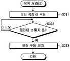
도 30은 도 28에 도시한 제2 상품 불출 판정 처리에 있어서의 복귀 처리(2)의 처리 내용을 도시하는 흐름도이다.Fig. 30 is a flowchart showing the processing contents of the return processing (2) in the second product dispensing determination processing shown in Fig.
이 복귀 처리(2)에 있어서 불출 제어부(60)는, 모터(43)를 정회전 구동시켜, 캐리어 스위치(45)로부터 온 신호가 주어지는 것을 기다리는 대기 상태가 된다(단계 S321, 단계 S322). 이와 같이 모터(43)를 정회전 구동시키면, 웜 기어(441) 및 중간 기어(442)를 통해 모터(43)의 구동력을 전달받은 출력 기어(443)는, 전방에서 봤을 때 시계 방향으로 회전한다.In this restoring process (2), the dispensing control unit (60) drives the motor (43) in the forward rotation and enters a standby state waiting for the signal from the carrier switch (45) to be given (steps S321 and S322). When the
이 결과, 캐리어 스위치(45)로부터 온 신호가 주어진 경우(단계 S322: 예), 불출 제어부(60)는, 모터(43)의 정회전 구동을 정지시키고(단계 S323), 그 후에 수순을 리턴시켜 이번 복귀 처리(2)를 종료한다. 이에 따르면, 출력 기어(443)가 대기 위치에 위치하게 된다.As a result, when a signal from the
이러한 복귀 처리(2)를 실시한 불출 제어부(60)는, 제2 상품 수납 통로(13b)의 제2 상품에 관해서는 매진된 것으로 하여 매진 판정을 하여(단계 S137), 그 취지를 자판기 제어부(100)에 출력하거나 하고 그 후에 수순을 리턴시켜 이번 처리를 종료한다. 이에 따르면, 제2 상품은 매진된 것으로 하여 매진 램프 등이 점등되고, 상기 제2 상품의 판매를 중지로 할 수 있다.The dispensing
이상 설명한 것과 같은 상품 불출 장치(20)에 따르면, 불출 제어부(60)가, 자판기 제어부(100)로부터 제1 상품 또는 제2 상품의 반출 지령을 받아 제1 상품 반출 장치(20a) 또는 제2 상품 반출 장치(20b)가 구동하는 경우에, 제1 매진 검지 스위치(26) 또는 제2 매진 검지 스위치(27)가 온 상태가 되어 온 신호가 주어짐으로써 상품 수납 통로(13)로부터 제1 상품 또는 제2 상품이 반출되었음을 판정하기 때문에, 상품의 불출을 검출하는 검출 수단 등을 이용하는 일 없이 제1 상품 또는 제2 상품이 불출되었음을 확실하게 검출할 수 있다.According to the
이와 같이 제1 상품 또는 제2 상품의 불출을 확실하게 검출할 수 있기 때문에, 상품 수납 통로(13)에서의 상품의 재고 관리 혹은 상품 수납 통로(13)의 상품의 매상 관리에 있어서의 오차 조정을 필요로 하지 않을 수 있고, 더구나 상품 구입자와의 사이에서 상품의 불출에 관한 문제 등을 피할 수 있다.Since the dispensing of the first commodity or the second commodity can be reliably detected as described above, it is possible to carry out the inventory control of the commodity in the
상기 상품 불출 장치(20)에 따르면, 불출 제어부(60)가, 미리 설정된 설정 시간 내에 대기 위치로부터 회전시킨 출력 기어(443)가 상기 대기 위치로 복귀하지 않는 경우에 있어서, 상기 설정 시간 내에 매진 검지 스위치(26, 27)로부터 온 신호가 주어질 때는 상기 설정 시간의 경과 후에도 출력 기어(443)를 계속하여 같은 방향으로 회전시키기 때문에(단계 S108, 단계 S128 참조), 제1 상품 또는 제2 상품을 불출한 후에, 출력 기어(443)를 역방향으로 회전시켜 제2 상품 또는 제1 상품을 불출해 버리는 것을 억제할 수 있다.According to the
상기 상품 불출 장치(20)에 따르면, 불출 제어부(60)가, 미리 설정된 설정 시간 내에 대기 위치로부터 회전시킨 출력 기어(443)가 상기 대기 위치로 복귀하지 않는 경우에 있어서, 상기 설정 시간 내에 매진 검지 스위치(26, 27)로부터 온 신호가 주어지지 않을 때에는 출력 기어(443)의 회전을 정지시켜 미리 정해진 대기 시간 내에 매진 검지 스위치(26, 27)로부터 온 신호가 주어지는지 여부를 판정하기 때문에, 설정 시간 경과 후에 있어서도 대기 시간 분만큼 제1 상품 또는 제2 상품이 불출되었음을 확실하게 검출할 수 있다.According to the
그리고, 불출 제어부(60)가, 상기 대기 시간 내에 매진 검지 스위치(26, 27)로부터 온 신호가 주어지는 경우에는, 상기 대기 시간의 경과 후에 출력 기어(443)를 같은 방향으로 회전시키기 때문에(단계 S112, 단계 S132 참조), 제1 상품 또는 제2 상품을 불출한 후에, 출력 기어(443)를 역방향으로 회전시켜 제2 상품 또는 제1 상품을 불출해 버리는 것을 억제할 수 있다. 한편, 불출 제어부(60)는, 상기 대기 시간 내에 매진 검지 스위치(26, 27)로부터 온 신호가 주어지지 않는 경우에는, 출력 기어(443)를 역방향으로 회전시켜 재시행 처리를 행하기 때문에, 제1 상품 또는 제2 상품의 불출을 재차 실행할 수 있다.When the dispensing
상기 상품 불출 장치(20)에 따르면, 불출 제어부(60)가, 출력 기어(443)가 대기 위치로 복귀한 경우에 제1 상품 또는 제2 상품의 반출을 판정하고 있지 않을 때는, 모터(43)의 정회전 구동 또는 역회전 구동을 계속하게 하기 때문에(단계 S113, 단계 S133 참조), 다음과 같은 작용 효과를 발휘한다. 즉, 출력 기어(443)가 대기 위치로 복귀하더라도 제1 상품 또는 제2 상품의 반출을 판정하고 있지 않을 때는, 모터(43)를 구동시키고 나서 하측 페달(28, 28′)이 한 번도 상품 없음 대기 자세가 되지 않음을 의미하고 있으며, 하측 페달(28, 28′)이 상품 수납 통로(13)로부터 퇴행 이동한 자세로 유지되어 상기 상품 수납 통로(13)의 상품이 아래쪽으로 계속해서 반출되고 있을 가능성이 있다. 그래서, 모터(43)의 구동을 유지하게 하여 하측 페달(28, 28′) 및 상측 페달(29, 29′)을 상품 수납 통로(13)에 대하여 재차 진퇴 이동시킴으로써, 상품 수납 통로(13)의 상품이 다수 불출되는 것을 피하고 있다.According to the
상기 상품 불출 장치(20)에 따르면, 제1 상품 반출 장치(20a)가, 상기 제1 상품 반출 장치(20a) 및 제2 상품 반출 장치(20b)의 구동원이 되는 모터(43)와, 반출 지령이 주어진 경우에 반출 지령에 따라서 제1 상품 반출 장치(20a) 및 제2 상품 반출 장치(20b)를 택일적으로 선택하여 모터(43)로부터의 구동력을 부여하는 구동 유닛(40)을 구비하고 있기 때문에, 반출 기구의 수에 대하여 구동원의 수를 줄일 수 있어, 제조 비용을 절감할 수 있다. 더구나, 제1 상품 반출 장치(20a)에 모터(43)를 포함하는 구동 유닛(40)을 구비하고 있기 때문에, 제1 상품 반출 장치(20a)만을 이용할 수도 있다. 즉, 상술한 것과 같이 짝수의 상품 수납 통로(13)가 전후로 나란하게 설치된 상품 수납 랙(10)뿐만 아니라, 홀수의 상품 수납 통로(13)가 전후로 나란하게 설치된 상품 수납 랙(10)에 대하여도 이용할 수 있다. 따라서, 제조 비용의 절감을 도모할 수 있음과 더불어, 전후에 인접되는 상품 수납 통로(13)의 수에 따라서 유연하게 대응할 수 있다.According to the
또한, 상품 불출 장치(20)에 따르면, 불출 제어부(60)가, 대기 위치로부터 일방향 혹은 타방향으로 향해서 회전시킨 출력 기어(443)가 소정 시간 내에 대기 위치로 복귀하지 않는 경우, 상기 출력 기어(443)를 타방향 혹은 일방향으로 향해서 회전시켜 대기 위치로 복귀시키는 복귀 처리 (1) 및 복귀 처리 (2)를 행하기 때문에, 출력 기어(443)를 대기 위치에 위치하게 하여, 판매를 중지한 상품 이외의 상품의 판매에 대비할 수 있다. 즉, 제1 상품 반출 장치(20a) 및 제2 상품 반출 장치(20b) 중 어느 한쪽의 상품이 판매 중지로 되어도 다른 쪽은 상품의 반출을 계속하게 할 수 있어, 상품 수납 통로(13)마다에 대응한 세심한 운용을 할 수 있게 되어, 판매 기회의 일탈을 억제할 수 있다.According to the
상기 상품 불출 장치(20)에 따르면, 구동원인 모터(43)가 직류 모터이기 때문에, 지역 전압이나 주파수 변동에 영향을 받기 어렵고, 여러 위치에서의 설치가 가능하게 된다.According to the
상기 상품 불출 장치(20)에 따르면, 제1 상품 반출 장치(20a)에 제1 매진 검지 스위치(26) 및 제2 매진 검지 스위치(27)를 설치했기 때문에, 제1 상품 반출 장치(20a)만을 이용할 수도 있으며, 이로써도 전후로 인접되는 상품 수납 통로(13)의 수에 따라서 유연하게 대응할 수 있어, 제1 상품 반출 장치(20a)에만 전장부가 배치되므로 하네스를 제1 상품 반출 장치(20a)에 집약하는 것이 가능하게 된다.According to the
이상, 본 발명의 적합한 실시형태에 관해서 설명했지만, 본 발명은 이것에 한정되는 것이 아니라, 다양한 변경을 행할 수 있다.While the preferred embodiments of the present invention have been described above, the present invention is not limited thereto, and various modifications can be made.
상술한 실시형태에서는, 제1 상품 불출 판정 처리 및 제2 상품 불출 판정 처리에 있어서 단계 S103 및 단계 S123에서 소정 시간이 경과한 후에, 한 번 모터(43)의 구동을 정지시키고 나서 단계 S107 및 단계 S127의 판단을 하고 있었지만, 본 발명에서는, 소정 시간이 경과한 후에 반출 있음이라고 판정했는지 여부를 판단하여, 반출 있음이라고 판정하지 않는 경우에만 모터의 구동을 정지시켜 대기 시간 내에 제1 매진 검지 스위치(26) 또는 제2 매진 검지 스위치(27)로부터의 온 신호가 주어지는지 여부를 판단하여도 좋다.In the above-described embodiment, after the predetermined time has elapsed in the steps S103 and S123 in the first product dispensing judgment processing and the second product dispensing judgment processing, the driving of the
상술한 실시형태에서는 특별히 설명하지 않았지만, 본 발명에서는, 상품 불출 판정 처리에 있어서, 모터를 구동시키고 나서 미리 정해진 금지 시간 내에는 매진 검지 스위치로부터의 온 신호의 입력을 금지하도록 하여도 좋다.Although not specifically described in the above-described embodiment, in the present invention, the input of the ON signal from the sold-out detection switch may be prohibited within a predetermined prohibition time after the motor is driven in the commodity dispense determination processing.
1: 본체 캐비닛, 4: 상품 수용고, 10: 상품 수납 랙, 13: 상품 수납 통로, 20: 상품 불출 장치, 20a: 제1 상품 반출 장치, 20b: 제2 상품 반출 장치, 26: 제1 매진 검지 스위치, 27: 제2 매진 검지 스위치, 28: 하측 페달, 29: 상측 페달, 35: 페달 링크, 40: 구동 유닛, 41: 유닛 베이스, 42: 유닛 커버, 43: 모터, 44: 기어 부재, 443: 출력 기어(출력 부재), 45: 캐리어 스위치, 46: 링크 레버, 60: 불출 제어부, 61: 메모리1: main body cabinet, 4: product receptacle, 10: commodity storage rack, 13: commodity receiving path, 20: commodity dispensing apparatus, 20a: first commodity export apparatus, 20b: second commodity export apparatus, And the second pedal is connected to the upper pedal by the pedal link so that the second pedal is engaged with the second pedal. 44: output gear (output member), 45: carrier switch, 46: link lever, 60: dispatch control section, 61: memory
Claims (4)
Translated fromKorean상기 하측 페달보다도 위쪽 영역에 있어서 상기 상품 수납 통로에 대하여 상측 페달의 선단부가 진퇴 이동하는 양태로 상기 베이스에 요동 가능하게 배치된 상측 페달
을 가지고,
대기 상태에 있어서는, 상기 상측 페달을 상기 상품 수납 통로로부터 퇴행 이동시키면서 상기 하측 페달을 상기 상품 수납 통로로 진출 이동시켜 상기 하측 페달이 상면에 최하위의 상품이 놓여 제1 대기 자세가 됨으로써 상기 상품이 아래쪽으로 향해서 이동하는 것을 규제하는 한편, 구동하는 경우에는, 상기 상측 페달을 상기 상품 수납 통로로 진출 이동시켜 최하위에서 2번째의 상품에 맞닿게 하면서 상기 하측 페달을 상기 상품 수납 통로로부터 퇴행 이동시킴으로써 최하위의 상품을 아래쪽으로 향해서 반출하는 상품 반출 장치를 구비한 상품 불출 장치에 있어서,
상기 하측 페달은, 상기 상품 수납 통로로 진출 이동한 상태에 있어서 상면에 상품이 놓이지 않은 경우에는, 상기 제1 대기 자세보다도 상기 하측 페달의 상기 선단부가 위쪽에 위치하는 제2 대기 자세로 되는 것이고,
상기 하측 페달이 상기 제2 대기 자세로 되는 경우에 제1 상태가 되는 한편, 상기 하측 페달이 상기 제2 대기 자세 이외의 것으로 되는 경우에 제2 상태가 되는 매진 검지 스위치와,
상기 상품 반출 장치가 구동하는 경우에, 상기 매진 검지 스위치가 제1 상태로 됨으로써 상기 상품 수납 통로로부터 상품이 불출되었음을 판정하는 제어 수단
을 구비한 것을 특징으로 하는 상품 불출 장치.A lower pedal arranged to be swingable on the base in such a manner that a distal end portion of the lower pedal moves forward and backward with respect to a commodity receiving passage accommodating the inserted commodity along a vertical direction,
And an upper pedal arranged to be swingable on the base in such a manner that a distal end portion of the upper pedal moves forward and backward with respect to the product accommodating passage in a region above the lower pedal
To have,
In the standby state, the lower pedal is advanced to the commodity receiving passage while the upper pedal is moved backward from the commodity receiving passage, and the lowest pedestal is placed on the upper surface so that the lower pedal is in the first waiting posture, While the upper pedal is moved to the goods receiving passage to cause the lower pedal to retreat from the goods receiving passage while the lower pedal is brought into contact with the second goods at the lowest position, A product dispensing apparatus having a product dispensing apparatus for taking out a product downward,
The lower pedal is in a second waiting posture in which the distal end portion of the lower pedal is positioned higher than the first waiting posture when the product is not placed on the upper surface in the state where the lower pedal is advanced to the product receiving passage,
A soldering detecting switch which is brought into a first state when the lower pedal is in the second waiting posture and a second state when the lower pedal is out of the second waiting posture,
And a control unit which, when the goods take-out apparatus is driven, determines that the goods have been dispensed from the goods storing path by the sold-
And an outlet for discharging the product.
출력 부재의 중심축 둘레로 회전 가능하게 배치되며 또한 대기 위치에 위치하는 경우에는 상기 상품 반출 장치가 대기 상태가 되게 하는 한편, 상기 대기 위치로부터 회전하는 경우에는 상기 상품 반출 장치를 구동시키는 출력 부재
를 구비하고,
상기 제어 수단은, 상기 출력 부재를 상기 대기 위치로부터 회전시키는 경우에, 상기 매진 검지 스위치가 제1 상태로 됨으로써 상기 상품 수납 통로로부터 상품이 불출되었음을 판정하는 것을 특징으로 하는 상품 불출 장치.The method according to claim 1,
And the output member is arranged to be rotatable about the central axis of the output member, and in the case of being positioned at the standby position, the product carry-out device is brought into the standby state,
And,
Wherein the control means judges that the article is discharged from the goods receiving passage when the soldering detecting switch is brought into the first state when the output member is rotated from the standby position.
Applications Claiming Priority (3)
| Application Number | Priority Date | Filing Date | Title |
|---|---|---|---|
| JPJP-P-2014-256560 | 2014-12-18 | ||
| JP2014256560 | 2014-12-18 | ||
| PCT/JP2015/081537WO2016098485A1 (en) | 2014-12-18 | 2015-11-10 | Commodity dispensing apparatus |
Publications (2)
| Publication Number | Publication Date |
|---|---|
| KR20170094160Atrue KR20170094160A (en) | 2017-08-17 |
| KR102458025B1 KR102458025B1 (en) | 2022-10-21 |
Family
ID=56126384
Family Applications (1)
| Application Number | Title | Priority Date | Filing Date |
|---|---|---|---|
| KR1020177014443AActiveKR102458025B1 (en) | 2014-12-18 | 2015-11-10 | Commodity dispensing apparatus |
Country Status (5)
| Country | Link |
|---|---|
| US (1) | US10540838B2 (en) |
| JP (1) | JP6341297B2 (en) |
| KR (1) | KR102458025B1 (en) |
| CN (1) | CN107004328B (en) |
| WO (1) | WO2016098485A1 (en) |
Cited By (1)
| Publication number | Priority date | Publication date | Assignee | Title |
|---|---|---|---|---|
| IT202100010061A1 (en)* | 2021-04-21 | 2022-10-21 | Am Automatic Machines S R L | VENDOR OF ITEMS |
Citations (5)
| Publication number | Priority date | Publication date | Assignee | Title |
|---|---|---|---|---|
| KR830002143A (en)* | 1979-01-29 | 1983-05-23 | 작끄 스트락 | Fluid-cooled circulation valve housing, especially for internal combustion engines, consisting of a cylinder with two discharge valves and its installation method |
| JPH11283096A (en)* | 1998-03-30 | 1999-10-15 | Sanden Corp | Article ejector |
| KR20010051947A (en)* | 1999-11-26 | 2001-06-25 | 다카노 야스아키 | A goods taking-out device of vending machine |
| JP2001188953A (en) | 1999-12-28 | 2001-07-10 | Fuji Electric Co Ltd | Vending machine product unloading device |
| KR20020069100A (en)* | 2001-02-22 | 2002-08-29 | 후지 덴끼 가부시키가이샤 | Commodity receiving and paying out device for automatic vending machine |
Family Cites Families (14)
| Publication number | Priority date | Publication date | Assignee | Title |
|---|---|---|---|---|
| US2369882A (en)* | 1943-09-21 | 1945-02-20 | John B Brock | Vending machine |
| US4423828A (en)* | 1981-07-20 | 1984-01-03 | Fuji Electric Company, Ltd. | Goods discharge mechanism and goods storage and discharge system of automatic vending machine |
| JPS59229696A (en)* | 1983-06-10 | 1984-12-24 | サンデン株式会社 | Goods conveying equipment for vending machine |
| JPS6324529Y2 (en)* | 1984-12-28 | 1988-07-05 | ||
| ES2066697B1 (en)* | 1992-12-29 | 1995-08-16 | Azkoyen Ind Sa | IMPROVEMENTS INTRODUCED IN AUTOMATIC PRODUCT VENDING COLUMNS. |
| US5511690A (en)* | 1993-05-20 | 1996-04-30 | Medical Laboratory Automation, Inc. | Automated feeder system and apparatus |
| JP2868057B2 (en)* | 1993-09-27 | 1999-03-10 | 株式会社クボタ | Direct loading type product dispensing device |
| JP2001283312A (en)* | 2000-03-31 | 2001-10-12 | Sanyo Electric Co Ltd | Commodity ejection device for automatic vending device |
| JP2002358565A (en)* | 2001-06-04 | 2002-12-13 | Kubota Corp | Vending machine product delivery device |
| CN1267865C (en)* | 2003-02-21 | 2006-08-02 | 富士电机株式会社 | Commodity moving out device for automatic vending machine |
| JP2007148552A (en)* | 2005-11-24 | 2007-06-14 | Fuji Electric Retail Systems Co Ltd | Merchandise conveying device of vending machine |
| CN101086794A (en)* | 2006-06-07 | 2007-12-12 | 富士电机零售设备系统株式会社 | Commodity move-out device of automatic seller |
| JP5621430B2 (en)* | 2010-09-10 | 2014-11-12 | 富士電機株式会社 | Vending machine product unloading device |
| JP2012221245A (en)* | 2011-04-08 | 2012-11-12 | Fuji Electric Retail Systems Co Ltd | Merchandise carrying-out device of automatic vending machine |
- 2015
- 2015-11-10KRKR1020177014443Apatent/KR102458025B1/enactiveActive
- 2015-11-10JPJP2016564733Apatent/JP6341297B2/enactiveActive
- 2015-11-10CNCN201580065393.7Apatent/CN107004328B/enactiveActive
- 2015-11-10WOPCT/JP2015/081537patent/WO2016098485A1/enactiveApplication Filing
- 2017
- 2017-05-23USUS15/602,788patent/US10540838B2/enactiveActive
Patent Citations (5)
| Publication number | Priority date | Publication date | Assignee | Title |
|---|---|---|---|---|
| KR830002143A (en)* | 1979-01-29 | 1983-05-23 | 작끄 스트락 | Fluid-cooled circulation valve housing, especially for internal combustion engines, consisting of a cylinder with two discharge valves and its installation method |
| JPH11283096A (en)* | 1998-03-30 | 1999-10-15 | Sanden Corp | Article ejector |
| KR20010051947A (en)* | 1999-11-26 | 2001-06-25 | 다카노 야스아키 | A goods taking-out device of vending machine |
| JP2001188953A (en) | 1999-12-28 | 2001-07-10 | Fuji Electric Co Ltd | Vending machine product unloading device |
| KR20020069100A (en)* | 2001-02-22 | 2002-08-29 | 후지 덴끼 가부시키가이샤 | Commodity receiving and paying out device for automatic vending machine |
Cited By (1)
| Publication number | Priority date | Publication date | Assignee | Title |
|---|---|---|---|---|
| IT202100010061A1 (en)* | 2021-04-21 | 2022-10-21 | Am Automatic Machines S R L | VENDOR OF ITEMS |
Also Published As
| Publication number | Publication date |
|---|---|
| US20170256118A1 (en) | 2017-09-07 |
| KR102458025B1 (en) | 2022-10-21 |
| CN107004328B (en) | 2019-07-19 |
| JPWO2016098485A1 (en) | 2017-09-21 |
| CN107004328A (en) | 2017-08-01 |
| US10540838B2 (en) | 2020-01-21 |
| JP6341297B2 (en) | 2018-06-13 |
| WO2016098485A1 (en) | 2016-06-23 |
Similar Documents
| Publication | Publication Date | Title |
|---|---|---|
| KR20160102382A (en) | Product delivery device | |
| KR20160102384A (en) | Product-dispensing device | |
| KR20160084364A (en) | Merchandise dispensing device | |
| KR20160102385A (en) | Product-dispensing device | |
| KR20160102383A (en) | Product payout device | |
| KR20170094160A (en) | Commodity dispensing apparatus | |
| KR20170088852A (en) | Product dispensing device | |
| JP6409547B2 (en) | Product dispensing device | |
| JP5810785B2 (en) | Product storage device | |
| JP6610750B2 (en) | Product dispensing device | |
| KR20170087891A (en) | Product dispensing device | |
| JP6485115B2 (en) | Product dispensing device | |
| JP6221755B2 (en) | Product carrying device | |
| JP2017126278A (en) | Commercial article carry-out device | |
| JP6447241B2 (en) | Product dispensing device | |
| JP2013065183A (en) | Automatic vending machine | |
| JP2013065184A (en) | Automatic vending machine |
Legal Events
| Date | Code | Title | Description |
|---|---|---|---|
| PA0105 | International application | Patent event date:20170526 Patent event code:PA01051R01D Comment text:International Patent Application | |
| PG1501 | Laying open of application | ||
| A201 | Request for examination | ||
| PA0201 | Request for examination | Patent event code:PA02012R01D Patent event date:20201020 Comment text:Request for Examination of Application | |
| E902 | Notification of reason for refusal | ||
| PE0902 | Notice of grounds for rejection | Comment text:Notification of reason for refusal Patent event date:20220512 Patent event code:PE09021S01D | |
| E701 | Decision to grant or registration of patent right | ||
| PE0701 | Decision of registration | Patent event code:PE07011S01D Comment text:Decision to Grant Registration Patent event date:20220726 | |
| GRNT | Written decision to grant | ||
| PR0701 | Registration of establishment | Comment text:Registration of Establishment Patent event date:20221019 Patent event code:PR07011E01D | |
| PR1002 | Payment of registration fee | Payment date:20221019 End annual number:3 Start annual number:1 | |
| PG1601 | Publication of registration |