KR20170093785A - Device - Google Patents
DeviceDownload PDFInfo
- Publication number
- KR20170093785A KR20170093785AKR1020177011394AKR20177011394AKR20170093785AKR 20170093785 AKR20170093785 AKR 20170093785AKR 1020177011394 AKR1020177011394 AKR 1020177011394AKR 20177011394 AKR20177011394 AKR 20177011394AKR 20170093785 AKR20170093785 AKR 20170093785A
- Authority
- KR
- South Korea
- Prior art keywords
- band
- mode
- uplink
- downlink
- timing
- Prior art date
- Legal status (The legal status is an assumption and is not a legal conclusion. Google has not performed a legal analysis and makes no representation as to the accuracy of the status listed.)
- Withdrawn
Links
- 230000005540biological transmissionEffects0.000claimsdescription278
- 238000012545processingMethods0.000claimsdescription96
- 238000000034methodMethods0.000claimsdescription47
- 238000006243chemical reactionMethods0.000claimsdescription19
- 230000008569processEffects0.000claimsdescription11
- 230000001360synchronised effectEffects0.000claimsdescription11
- 238000004891communicationMethods0.000abstractdescription144
- 101000741965Homo sapiens Inactive tyrosine-protein kinase PRAG1Proteins0.000description160
- 102100038659Inactive tyrosine-protein kinase PRAG1Human genes0.000description160
- 238000010586diagramMethods0.000description36
- 230000011664signalingEffects0.000description23
- 230000006870functionEffects0.000description21
- 230000008859changeEffects0.000description12
- 238000005259measurementMethods0.000description9
- 230000007704transitionEffects0.000description9
- 230000010267cellular communicationEffects0.000description6
- 230000004044responseEffects0.000description6
- 230000003111delayed effectEffects0.000description5
- 230000000694effectsEffects0.000description5
- 230000002776aggregationEffects0.000description4
- 238000004220aggregationMethods0.000description4
- 238000010295mobile communicationMethods0.000description4
- 238000004590computer programMethods0.000description3
- 230000001413cellular effectEffects0.000description2
- 230000007774longtermEffects0.000description2
- 230000001151other effectEffects0.000description2
- 239000004065semiconductorSubstances0.000description2
- 230000001133accelerationEffects0.000description1
- 239000000969carrierSubstances0.000description1
- 230000000295complement effectEffects0.000description1
- 239000006185dispersionSubstances0.000description1
- 238000005516engineering processMethods0.000description1
- 229910052738indiumInorganic materials0.000description1
- 239000004973liquid crystal related substanceSubstances0.000description1
- 229910044991metal oxideInorganic materials0.000description1
- 150000004706metal oxidesChemical class0.000description1
- 238000012986modificationMethods0.000description1
- 230000004048modificationEffects0.000description1
- 239000013307optical fiberSubstances0.000description1
- 238000009482thermal adhesion granulationMethods0.000description1
Images


Classifications
- H—ELECTRICITY
- H04—ELECTRIC COMMUNICATION TECHNIQUE
- H04W—WIRELESS COMMUNICATION NETWORKS
- H04W56/00—Synchronisation arrangements
- H04W56/004—Synchronisation arrangements compensating for timing error of reception due to propagation delay
- H04W56/0045—Synchronisation arrangements compensating for timing error of reception due to propagation delay compensating for timing error by altering transmission time
- H—ELECTRICITY
- H04—ELECTRIC COMMUNICATION TECHNIQUE
- H04W—WIRELESS COMMUNICATION NETWORKS
- H04W72/00—Local resource management
- H04W72/12—Wireless traffic scheduling
- H—ELECTRICITY
- H04—ELECTRIC COMMUNICATION TECHNIQUE
- H04L—TRANSMISSION OF DIGITAL INFORMATION, e.g. TELEGRAPHIC COMMUNICATION
- H04L5/00—Arrangements affording multiple use of the transmission path
- H04L5/14—Two-way operation using the same type of signal, i.e. duplex
- H—ELECTRICITY
- H04—ELECTRIC COMMUNICATION TECHNIQUE
- H04W—WIRELESS COMMUNICATION NETWORKS
- H04W28/00—Network traffic management; Network resource management
- H04W28/02—Traffic management, e.g. flow control or congestion control
- H04W28/06—Optimizing the usage of the radio link, e.g. header compression, information sizing, discarding information
- H—ELECTRICITY
- H04—ELECTRIC COMMUNICATION TECHNIQUE
- H04W—WIRELESS COMMUNICATION NETWORKS
- H04W56/00—Synchronisation arrangements
- H—ELECTRICITY
- H04—ELECTRIC COMMUNICATION TECHNIQUE
- H04W—WIRELESS COMMUNICATION NETWORKS
- H04W72/00—Local resource management
- H04W72/04—Wireless resource allocation
- H04W72/042—
- H—ELECTRICITY
- H04—ELECTRIC COMMUNICATION TECHNIQUE
- H04W—WIRELESS COMMUNICATION NETWORKS
- H04W72/00—Local resource management
- H04W72/04—Wireless resource allocation
- H04W72/044—Wireless resource allocation based on the type of the allocated resource
- H04W72/0446—Resources in time domain, e.g. slots or frames
- H04W72/1289—
Landscapes
- Engineering & Computer Science (AREA)
- Signal Processing (AREA)
- Computer Networks & Wireless Communication (AREA)
- Mobile Radio Communication Systems (AREA)
- Time-Division Multiplex Systems (AREA)
Abstract
Translated fromKorean
Description
Translated fromKorean본 개시는, 장치에 관한 것이다.The present disclosure relates to an apparatus.
최근 들어, 스마트폰의 보급에 따라, 이동체 통신 네트워크에 있어서의 트래픽이 급증하고 있다. 장소 및/또는 시간대에 따라, 다운링크(downlink: DL)의 트래픽과 업링크(uplink: UL)의 트래픽의 비율이 변동된다. 그 때문에, 트래픽에 따라, DL을 위한 무선 리소스의 양과, UL을 위한 무선 리소스의 양을 유연하게 조정함으로써, 무선 리소스를 효율적으로 사용할 것이 요망된다.Recently, with the spread of smart phones, traffic in a mobile communication network is rapidly increasing. The ratio of the traffic of the downlink (DL) and the traffic of the uplink (UL) varies depending on the location and / or the time zone. Therefore, it is desired to efficiently use radio resources by flexibly adjusting the amount of radio resources for the DL and the amount of radio resources for the UL in accordance with the traffic.
LTE(Long Term Evolution)에서는, 복신 방식으로서, FDD(Frequency Division Duplex) 및 TDD(Time Division Duplex)가 서포트되고 있다. TDD에서는, 트래픽에 따라, UL/DL 컨피규레이션을 동적으로 변경함으로써, 무선 프레임에 있어서의 UL 서브프레임과 DL 서브프레임의 비율을 변경할 수 있다. 즉, TDD에서는, DL을 위한 무선 리소스의 양과, UL을 위한 무선 리소스의 양을 유연하게 조정할 수 있다. 한편, FDD에서는, DL 대역과 UL 대역이 미리 결정되어 있으므로, DL을 위한 무선 리소스의 양과, UL을 위한 무선 리소스의 양을 유연하게 조정할 수 없다. FDD에 있어서, 보다 많은 DL 대역과 보다 적은 UL 대역을 캐리어 애그리게이션에 의해 사용하는 것도 가능하지만, 그 결과, UL 대역의 무선 리소스의 사용률이 낮아져서, 무선 리소스가 효율적으로 사용된다고는 할 수 없다.In LTE (Long Term Evolution), FDD (Frequency Division Duplex) and TDD (Time Division Duplex) are supported as duplex systems. In the TDD, the UL / DL configuration can be changed dynamically according to the traffic, thereby changing the ratio of the UL subframe and the DL subframe in the radio frame. That is, in TDD, the amount of radio resources for DL and the amount of radio resources for UL can be flexibly adjusted. On the other hand, in the FDD, since the DL band and the UL band are predetermined, the amount of radio resources for the DL and the amount of radio resources for the UL can not be flexibly adjusted. In the FDD, it is also possible to use more DL bands and fewer UL bands by carrier aggregation, but as a result, the utilization rate of radio resources in the UL bands is lowered, and wireless resources can not be efficiently used.
따라서, FDD의 UL 대역을 시분할로 DL 및 UL의 양쪽에 사용하는 방법이 검토되고 있다. 당해 방법은, 플렉시블 듀플렉스(Flexible Duplex)라고 불릴 수 있다. 예를 들어, 특허문헌 1에는, FDD의 UL 대역을 TDD 모드에서 사용하는 기술이 개시되어 있다.Therefore, a method of using the UL band of the FDD in both DL and UL by time division has been studied. This method can be called a flexible duplex. For example,
그러나, FDD의 UL 대역을 시분할로 DL 및 UL의 양쪽에 사용하는 경우에는, 당해 UL 대역에서 무선 통신이 양호하게 행하여지지 않을 가능성이 있다.However, when the UL band of the FDD is used for both DL and UL in a time-division manner, there is a possibility that wireless communication in the UL band is not performed well.
따라서, FDD의 UL 대역을 시분할로 DL 및 UL의 양쪽에 사용하는 경우에 당해 UL 대역에서 보다 양호하게 무선 통신을 행하는 것을 가능하게 하는 구조가 제공되는 것이 바람직하다.Therefore, it is desirable to provide a structure that enables wireless communication to be performed better in the UL band when the UL band of the FDD is used in both DL and UL in a time division manner.
본 개시에 의하면, FDD의 업링크 대역이 업링크에 사용되는 제1 모드와, 상기 업링크 대역이 시분할에 의해 다운링크 및 업링크의 양쪽에 사용되는 제2 모드 사이에서, 상기 업링크 대역에 관한 동작 모드를 전환하는 전환부와, 상기 업링크 대역에 대응하는 FDD의 다운링크 대역에 관한 다운링크 수신 타이밍을 기준으로 하는 제1 타이밍 어드밴스에 관한 지시, 및 상기 업링크 대역에 관한 다운링크 수신 타이밍을 기준으로 하는 제2 타이밍 어드밴스에 관한 지시를 행하는 제어부를 구비하는 장치가 제공된다.According to the present disclosure, in a first mode in which the uplink band of the FDD is used for the uplink and a second mode in which the uplink band is used for both the downlink and the uplink by time division, An instruction regarding a first timing advance based on a downlink reception timing with respect to a downlink band of an FDD corresponding to the uplink band, and a downlink reception There is provided an apparatus comprising a control section for giving an instruction regarding a second timing advance based on timing.
또한, 본 개시에 의하면, FDD의 업링크 대역이 업링크에 사용되는 제1 모드와, 상기 업링크 대역이 시분할에 의해 다운링크 및 업링크의 양쪽에 사용되는 제2 모드 사이에서, 상기 업링크 대역에 관한 동작 모드를 전환하는 전환부와, 상기 동작 모드가 상기 제2 모드인 경우에, 상기 업링크 대역에 대응하는 FDD의 다운링크 대역에 관한 다운링크 송신 타이밍과, 상기 업링크 대역에 관한 다운링크 송신 타이밍을 동기시키는 제어부를 구비하는 장치가 제공된다.Further, according to the present disclosure, in a first mode in which the uplink band of the FDD is used for the uplink and a second mode in which the uplink band is used for both the downlink and the uplink by time division, The downlink transmission timing for the downlink band of the FDD corresponding to the uplink band and the downlink transmission timing for the downlink band corresponding to the downlink band corresponding to the downlink band corresponding to the uplink band when the operation mode is the second mode, There is provided an apparatus including a control section for synchronizing downlink transmission timing.
또한, 본 개시에 의하면, FDD의 업링크 대역이 업링크에 사용되는 제1 모드와, 상기 업링크 대역이 시분할에 의해 다운링크 및 업링크의 양쪽에 사용되는 제2 모드 사이에서의, 상기 업링크 대역에 관한 동작 모드의 전환을 나타내는 정보를 취득하는 취득부와, 상기 동작 모드가 상기 제1 모드인 경우에, 상기 업링크 대역에서의 업링크 송신을 위한 처리를 행하고, 상기 동작 모드가 상기 제2 모드인 경우에, 상기 업링크 대역에서의 다운링크 수신 및 업링크 송신을 위한 처리를 행하는 제어부를 구비하는 장치가 제공된다. 상기 제어부는, 상기 동작 모드가 상기 제1 모드인지 또는 상기 제2 모드인지에 상관없이, 상기 업링크 대역에 대응하는 FDD의 다운링크 대역에 관한 다운링크 수신 타이밍에 기초하여, 상기 업링크 대역에 관한 업링크 송신 타이밍을 조정한다.Further, according to the present disclosure, there is provided a method of controlling uplink transmission in a first mode in which an uplink band of an FDD is used for an uplink, and a second mode in which the uplink band is used in both downlink and uplink by time division. An acquisition section for acquiring information indicating switching of an operation mode related to a link band, and a processing section for performing processing for uplink transmission in the uplink band when the operation mode is the first mode, And a control section for performing processing for downlink reception and uplink transmission in the uplink band in the second mode. Wherein the control unit is configured to determine whether or not the operation mode is the first mode or the second mode based on the downlink reception timing related to the downlink band of the FDD corresponding to the uplink band, And adjusts the uplink transmission timing.
이상 설명한 바와 같이 본 개시에 의하면, FDD의 UL 대역을 시분할로 DL 및 UL의 양쪽에 사용하는 경우에 당해 UL 대역에서 보다 양호하게 무선 통신을 행하는 것이 가능해진다. 또한, 상기 효과는 반드시 한정적인 것은 아니고, 상기 효과와 함께, 또는 상기 효과 대신에, 본 명세서에 나타난 어느 효과, 또는 본 명세서로부터 파악될 수 있는 다른 효과가 발휘되어도 된다.As described above, according to the present disclosure, when the UL band of the FDD is used for both the DL and the UL in a time division manner, the wireless communication can be performed better in the UL band. Further, the effect is not necessarily limited, and any effect shown in this specification, or other effects that can be grasped from this specification, may be exercised together with or instead of the above effect.
도 1은 FDD의 케이스에 있어서의 TA의 일례를 설명하기 위한 설명도이다.
도 2는 TDD의 케이스에 있어서의 TA의 일례를 설명하기 위한 설명도이다.
도 3은 FDD-LTE에 있어서의 ACK/NACK의 송신의 일례를 설명하기 위한 설명도이다.
도 4는 TDD의 UL/DL 컨피규레이션의 예를 설명하기 위한 설명도이다.
도 5는 본 개시의 실시 형태에 따른 시스템의 개략적인 구성의 일례를 도시하는 설명도이다.
도 6은 기지국이 매크로셀의 기지국인 케이스를 설명하기 위한 설명도이다.
도 7은 기지국이 스몰셀의 기지국인 케이스를 설명하기 위한 설명도이다.
도 8은 동 실시 형태에 따른 기지국의 구성의 일례를 도시하는 블록도이다.
도 9는 동 실시 형태에 따른 단말 장치의 구성의 일례를 도시하는 블록도이다.
도 10은 동 실시 형태에 따른 단말 장치의 무선 통신부에 포함되는 하드웨어의 일례를 설명하기 위한 설명도이다.
도 11은 UL 대역에서의 UL과 DL의 전환에 기인하는 DL 송신 타이밍의 지연의 일례를 설명하기 위한 설명도이다.
도 12는 제1 TA 및 제2 TA의 예를 설명하기 위한 설명도이다.
도 13은 제1 실시 형태에 따른 제1 모드에서의 처리의 개략적인 흐름의 일례를 도시하는 시퀀스도이다.
도 14는 제1 실시 형태에 따른 제2 모드에서의 처리의 개략적인 흐름의 일례를 도시하는 시퀀스도이다.
도 15는 제2 실시 형태에 따른 제2 모드에서의 처리의 개략적인 흐름의 일례를 도시하는 시퀀스도이다.
도 16은 DL 대역 및 UL 대역에 관한 DL 송신 타이밍의 예를 설명하기 위한 설명도이다.
도 17은 제3 실시 형태에 따른 처리의 개략적인 흐름의 일례를 도시하는 시퀀스도이다.
도 18은 제4 실시 형태에 따른 처리의 개략적인 흐름의 일례를 도시하는 시퀀스도이다.
도 19는 DL 데이터에 관한 ACK/NACK가 송신되는 서브프레임이 DL 서브프레임인 예를 설명하기 위한 설명도이다.
도 20은 DL 레퍼런스 UL/DL 컨피규레이션을 위하여 정의된 서브프레임의 일례를 설명하기 위한 설명도이다.
도 21은 DL 대역에서 송신되는 DL 데이터에 관한 ACK/NACK의 송신의 일례를 설명하기 위한 설명도이다.
도 22는 UL 대역에서 송신되는 DL 데이터에 관한 ACK/NACK의 송신의 일례를 설명하기 위한 설명도이다.
도 23은 UL 레퍼런스 UL/DL 컨피규레이션을 위하여 정의된 서브프레임의 일례를 설명하기 위한 설명도이다.
도 24는 UL 대역에서 송신되는 UL 데이터에 관한 ACK/NACK의 송신의 일례를 설명하기 위한 설명도이다.
도 25는 제5 실시 형태에 따른 처리의 개략적인 흐름의 일례를 도시하는 시퀀스도이다.
도 26은 eNB의 개략적인 구성의 제1 예를 도시하는 블록도이다.
도 27은 eNB의 개략적인 구성의 제2 예를 도시하는 블록도이다.
도 28은 스마트폰의 개략적인 구성의 일례를 도시하는 블록도이다.
도 29는 카 내비게이션 장치의 개략적인 구성의 일례를 도시하는 블록도이다.1 is an explanatory view for explaining an example of a TA in the case of FDD.
2 is an explanatory view for explaining an example of TA in the case of TDD.
3 is an explanatory diagram for explaining an example of ACK / NACK transmission in FDD-LTE.
4 is an explanatory view for explaining an example of UL / DL configuration of TDD.
5 is an explanatory view showing an example of a schematic configuration of a system according to the embodiment of the present disclosure;
6 is an explanatory diagram for explaining a case where a base station is a base station of a macro cell.
FIG. 7 is an explanatory diagram for explaining a case where a base station is a base station of a small cell.
8 is a block diagram showing an example of the configuration of a base station according to the present embodiment.
Fig. 9 is a block diagram showing an example of the configuration of the terminal device according to the embodiment.
10 is an explanatory view for explaining an example of hardware included in the wireless communication unit of the terminal apparatus according to the embodiment.
11 is an explanatory view for explaining an example of delay of DL transmission timing due to switching of UL and DL in the UL band.
12 is an explanatory view for explaining examples of the first TA and the second TA.
13 is a sequence diagram showing an example of a schematic flow of processing in the first mode according to the first embodiment.
14 is a sequence diagram showing an example of a schematic flow of processing in the second mode according to the first embodiment.
15 is a sequence diagram showing an example of a schematic flow of processing in the second mode according to the second embodiment.
16 is an explanatory view for explaining an example of DL transmission timing with respect to the DL band and the UL band;
17 is a sequence diagram showing an example of a schematic flow of processing according to the third embodiment.
18 is a sequence diagram showing an example of a schematic flow of processing according to the fourth embodiment.
19 is an explanatory view for explaining an example in which a subframe in which ACK / NACK for DL data is transmitted is a DL subframe.
20 is an explanatory view for explaining an example of a subframe defined for the DL reference UL / DL configuration.
21 is an explanatory view for explaining an example of transmission of ACK / NACK with respect to DL data transmitted in the DL band;
22 is an explanatory diagram for explaining an example of ACK / NACK transmission regarding DL data transmitted in the UL band;
23 is an explanatory view for explaining an example of a subframe defined for UL reference UL / DL configuration;
24 is an explanatory diagram for explaining an example of transmission of ACK / NACK with respect to UL data transmitted in the UL band;
25 is a sequence diagram showing an example of a schematic flow of processing according to the fifth embodiment.
26 is a block diagram showing a first example of the schematic configuration of the eNB.
27 is a block diagram showing a second example of the schematic configuration of the eNB.
28 is a block diagram showing an example of a schematic configuration of a smartphone.
29 is a block diagram showing an example of a schematic configuration of a car navigation apparatus.
이하에 첨부된 도면을 참조하면서, 본 개시의 바람직한 실시 형태에 대하여 상세하게 설명한다. 또한, 본 명세서 및 도면에 있어서, 실질적으로 동일한 기능 구성을 갖는 구성 요소에 대해서는, 동일한 번호를 부여함으로써 중복 설명을 생략한다.DETAILED DESCRIPTION OF THE PREFERRED EMBODIMENTS Hereinafter, preferred embodiments of the present invention will be described in detail with reference to the accompanying drawings. In the present specification and drawings, elements having substantially the same functional configuration are denoted by the same reference numerals, and redundant description will be omitted.
또한, 설명은 이하의 순서로 행하는 것으로 한다.The description will be made in the following order.
1. 서론1. Introduction
2. 시스템의 개략적인 구성2. Schematic configuration of the system
3. 각 장치의 구성3. Configuration of each device
3.1. 기지국의 구성 3.1. Base station configuration
3.3. 단말 장치의 구성 3.3. Configuration of terminal device
4. 제1 실시 형태4. First Embodiment
4.1. 기술적 과제 4.1. Technical Challenge
4.2. 기술적 특징 4.2. Technical Features
4.3. 처리의 흐름 4.3. Flow of processing
5. 제2 실시 형태5. Second Embodiment
5.1. 기술적 과제 5.1. Technical Challenge
5.2. 기술적 특징 5.2. Technical Features
5.3. 처리의 흐름 5.3. Flow of processing
6. 제3 실시 형태6. Third Embodiment
6.1. 기술적 과제 6.1. Technical Challenge
6.2. 기술적 특징 6.2. Technical Features
6.3. 처리의 흐름 6.3. Flow of processing
7. 제4 실시 형태7. Fourth Embodiment
7.1. 기술적 과제 7.1. Technical Challenge
7.2. 기술적 특징 7.2. Technical Features
7.3. 처리의 흐름 7.3. Flow of processing
8. 제5 실시 형태8. Fifth Embodiment
8.1. 기술적 과제 8.1. Technical Challenge
8.2. 기술적 특징 8.2. Technical Features
8.3. 처리의 흐름 8.3. Flow of processing
9. 응용예9. Application Examples
9.1. 기지국에 관한 응용예 9.1. Application example on base station
9.2. 단말 장치에 관한 응용예 9.2. Application example concerning terminal device
10. 정리10. Theorem
<<1. 서론>><< 1. Introduction >>
처음에, 도 1 내지 도 4를 참조하여, UL 송신 타이밍의 조정, 및 ACK(Acknowledgement)/NACK(Negative Acknowledgement)의 송신 타이밍을 설명한다.First, the transmission timing of the UL transmission timing and the transmission timing of ACK (acknowledgment) / NACK (negative acknowledgment) will be described with reference to FIG. 1 to FIG.
(1) UL 송신 타이밍의 조정(1) Adjustment of UL transmission timing
(a) 타이밍 어드밴스(Timing Advance: TA)(a) Timing Advance (TA)
기지국(예를 들어, eNB(evolved Node B))과 단말 장치(예를 들어, UE(User Equipment)) 간의 거리 및 전반 지연은 단말 장치에 따라 상이하다. 그 때문에, 복수의 단말 장치로부터의 UL 신호의 기지국에 있어서의 수신 타이밍이 동기하도록, 상기 복수의 단말 장치의 각각의 UL 송신 타이밍이 조정된다. 보다 구체적으로는, 예를 들어, 기지국은, 타이밍 어드밴스(TA) 커맨드를 단말 장치에 통지하고, 단말 장치는, 당해 TA 커맨드에 기초하여, UL 송신 타이밍을 조정(adjust)한다.The distance and the propagation delay between a base station (e.g., evolved Node B (eNB)) and a terminal device (e.g., UE (User Equipment) Therefore, the UL transmission timing of each of the plurality of terminal apparatuses is adjusted so that the reception timings of the UL signals of the plurality of terminal apparatuses are synchronized with each other. More specifically, for example, the base station notifies the terminal apparatus of a timing advance (TA) command, and the terminal apparatus adjusts the UL transmission timing based on the TA command.
(a-1) TA의 초기값(a-1) Initial value of TA
예를 들어, 단말 장치가 랜덤 액세스 프리앰블을 송신하면, 기지국은, TA(예를 들어, TA=0 내지 1282))를 나타내는 TA 커맨드를 포함하는 랜덤 액세스 리스펀스를 상기 단말 장치로 송신한다. 그리고, 상기 단말 장치는, TA부터 NTA(NTA=TA*16)를 산출한다. 그리고, 상기 단말 장치는, DL 수신 타이밍과, NTA에 기초하여, UL 송신 타이밍을 조정한다.For example, when the terminal apparatus transmits a random access preamble, the base station transmits to the terminal apparatus a random access response including a TA command indicating TA (for example, TA = 0 to 1282). Then, the terminal device calculates TA to NTA (NTA = TA * 16). Then, the terminal apparatus adjusts the UL transmission timing based on the DL reception timing and the NTA .
FDD의 케이스에서는, TA(즉, UL 송신 타이밍과 DL 수신 타이밍의 차분)는 NTA*TS이다. TS는, 1/30.72마이크로초(us)이다.In the case of FDD, TA (i.e., the difference between the UL transmission timing and the DL reception timing) is NTA * TS. TS is 1 / 30.72 microseconds (us).
한편, TDD의 케이스에서는, TA는, (NTA+624)*TS이다. 624*TS의 오프셋은, 기지국에 있어서의 UL 수신으로부터 DL 송신으로의 전환을 허용하기 위한 것이다.On the other hand, in the case of TDD, TA is (NTA +624) * TS. Offset of 624 * TS, is to allow the transition from DL UL transmitted from the reception of the base station.
이와 같이, NTA로부터 하나의 TA가 유도되므로, NTA는, TA를 나타내는 정보라고 할 수 있다.Thus, since one TA is derived from NTA , NTA can be referred to as information indicating TA.
(a-2) TA의 갱신(a-2) Updating TA
랜덤 액세스 처리 후에는, 기지국은, TA의 갱신을 위해서, TA(예를 들어, TA=0 내지 63)를 나타내는 TA 커맨드를 단말 장치에 통지한다. 그리고, 상기 단말 장치는, NTA,old 및 TA로부터, NTA,New(NTA, New=NTA, old+(TA-31)*16)를 산출한다. 그리고, 상기 단말 장치는, DL 수신 타이밍과, NTA,New에 기초하여, UL 송신 타이밍을 조정한다.After the random access process, the base station, and notifies the TA command that indicates an order update of the TA, TA (for example, TA = 0 to 63) to the terminal device. Then, the terminal apparatus calculates NTA,New (NTA, New = NTA, old + (TA -31) * 16) from NTA,old and TA. Then, the terminal apparatus adjusts the UL transmission timing based on the DL reception timing and NTA,New .
(a-3) TA의 예(a-3) Example of TA
도 1은, FDD의 케이스에 있어서의 TA의 일례를 설명하기 위한 설명도이다. 도 1을 참조하면, FDD의 케이스에 있어서의 기지국 및 단말 장치의 송수신 타이밍이 도시되어 있다. 예를 들어, 기지국에서는, DL 송신 타이밍과 UL 수신 타이밍이 동기하고 있다. 환언하면, 당해 기지국에서는, DL 프레임 타이밍과 UL 프레임 타이밍이 동기하고 있다. 한편, 전반 지연에 기인하여 단말 장치에 있어서의 DL 수신 타이밍은, 상기 기지국에 있어서의 DL 송신 타이밍보다도 늦고, 상기 단말 장치에 있어서의 UL 송신 타이밍은, 상기 기지국에 있어서의 UL 수신 타이밍보다도 빠르다. 상기 단말 장치에 있어서의 UL 송신 타이밍은, 상기 단말 장치에 있어서의 DL 수신 타이밍보다도 TA(91)만큼 빠르다.1 is an explanatory view for explaining an example of TA in the case of FDD. Referring to Fig. 1, transmission and reception timings of a base station and a terminal apparatus in a case of FDD are shown. For example, in the base station, the DL transmission timing and the UL reception timing are synchronized. In other words, the base station synchronizes the DL frame timing with the UL frame timing. On the other hand, the DL reception timing in the terminal apparatus due to the propagation delay is later than the DL transmission timing in the base station, and the UL transmission timing in the terminal apparatus is earlier than the UL reception timing in the base station. The UL transmission timing in the terminal apparatus is earlier by TA (91) than the DL receiving timing in the terminal apparatus.
도 2는, TDD의 케이스에 있어서의 TA의 일례를 설명하기 위한 설명도이다. 도 2를 참조하면, TDD의 케이스에 있어서의 기지국 및 단말 장치의 송수신 타이밍이 도시되어 있다. TDD의 케이스에서도, 전반 지연에 기인하여 단말 장치에 있어서의 DL 수신 타이밍은, 기지국에 있어서의 DL 송신 타이밍보다도 늦고, 상기 단말 장치에 있어서의 UL 송신 타이밍은, 상기 기지국에 있어서의 UL 수신 타이밍보다도 빠르다. 상기 단말 장치에 있어서의 UL 송신 타이밍은, 상기 단말 장치에 있어서의 DL 수신 타이밍(95)보다도 TA(93)만큼 빠르다. 또한, 기지국에 있어서, UL 수신으로부터 DL 송신으로의 전환에 시간(97)을 요한다. 마찬가지로, 단말 장치에 있어서도, DL 수신으로부터 UL 송신으로의 전환에 시간(99)을 요한다.2 is an explanatory view for explaining an example of TA in the case of TDD. Referring to Fig. 2, timing of transmission and reception of base stations and terminal devices in the case of TDD is shown. Even in the TDD case, the DL reception timing in the terminal apparatus due to the propagation delay is later than the DL transmission timing in the base station, and the UL transmission timing in the terminal apparatus is lower than the UL reception timing in the base station fast. The UL transmission timing in the terminal apparatus is earlier by TA (93) than the DL reception timing (95) in the terminal apparatus. Further, at the base station, it takes
(b) 타이밍 어드밴스 그룹(Timing Advance Group: TAG)(b) Timing Advance Group (TAG)
단말 장치는, 캐리어 애그리게이션에 의해, 최대 5개의 컴포넌트 캐리어(Component Carrier: CC)를 동시에 사용할 수 있다. 단말 장치는, DL 수신 타이밍과, TA를 나타내는 정보에 기초하여, 프라이머리 셀의 PUCCH(Physical Uplink Control Channel)/PUSCH(Physical Uplink Shared Channel)/SRS(Sounding Reference Signal)에 관한 UL 송신 타이밍을 조정한다. 또한, 단말 장치는, DL 수신 타이밍과, TA를 나타내는 정보에 기초하여, 세컨더리 셀의 PUSCH/SRS에 관한 UL 송신 타이밍을 조정한다.The terminal apparatus can simultaneously use up to five component carriers (CCs) by carrier aggregation. The terminal apparatus adjusts the UL transmission timing for the PUCCH / PUSCH / SRS (Sounding Reference Signal) of the primary cell based on the DL reception timing and the information indicating the TA. do. Further, the terminal apparatus adjusts the UL transmission timing with respect to the PUSCH / SRS of the secondary cell based on the DL reception timing and the information indicating TA.
예를 들어, 동일한 기지국이, 동기한 복수의 CC를 사용하는 경우에는, 당해 복수의 CC에 공통인 TA가 사용된다. 이 경우에, 상기 복수의 CC는, 동일한 타이밍 어드밴스 그룹(TAG)에 속하고, 상기 TA는, 이 TAG의 TA이다. 단말 장치는, 복수의 TAG의 TA를 관리한다. 단말 장치는, 어떤 TAG에 속하는 CC에 관한 UL 송신 타이밍을, 당해 어떤 TAG의 TA에 기초하여 조정한다. TA 커맨드 MAC(Medium Access Control) 컨트롤 엘리먼트는, 2비트의 TAG ID, 및 6비트의 TA 커맨드를 포함한다.For example, when the same base station uses a plurality of synchronized CCs, TA common to the plurality of CCs is used. In this case, the plurality of CCs belong to the same timing advance group (TAG), and the TA is the TA of this TAG. The terminal apparatus manages the TA of a plurality of TAGs. The terminal apparatus adjusts the UL transmission timing for the CC belonging to a TAG based on the TA of the TAG. The TA Command Medium Access Control (MAC) control element includes a 2-bit TAG ID and a 6-bit TA command.
(2) ACK/NACK의 송신(2) Transmission of ACK / NACK
(a) FDD(a) FDD
FDD-LTE에서는, DL 데이터에 관한 ACK/NACK는, 당해 DL 데이터가 송신되는 서브프레임의 4서브프레임 후의 서브프레임에서 송신된다. 이하, 이 점에 대하여 도 3을 참조하여 구체예를 설명한다.In the FDD-LTE, the ACK / NACK for DL data is transmitted in the sub-frame after 4 subframes of the subframe in which the DL data is transmitted. Hereinafter, a specific example will be described with reference to Fig. 3 in this respect.
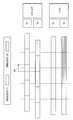
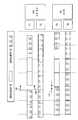
도 3은, FDD-LTE에 있어서의 ACK/NACK의 송신의 일례를 설명하기 위한 설명도이다. 도 3을 참조하면, FDD의 DL 대역의 서브프레임과, FDD의 UL 대역의 서브프레임이 도시되어 있다. 예를 들어, DL 데이터가, 서브프레임 번호가 0인 서브프레임에서 송신되면, 당해 DL 데이터에 관한 ACK/NACK는, 서브프레임 번호가 4인 서브프레임에서 송신된다. 마찬가지로, DL 데이터가, 서브프레임 번호가 1인 서브프레임에서 송신되면, 당해 DL 데이터에 관한 ACK/NACK는, 서브프레임 번호가 5인 서브프레임에서 송신된다.3 is an explanatory diagram for explaining an example of ACK / NACK transmission in FDD-LTE. Referring to FIG. 3, a subframe in the DL band of the FDD and a subframe in the UL band of the FDD are shown. For example, when DL data is transmitted in a subframe in which the subframe number is 0, ACK / NACK for the DL data is transmitted in the subframe in which the subframe number is 4. Likewise, when DL data is transmitted in a subframe having a subframe number of 1, ACK / NACK of the DL data is transmitted in a subframe having a subframe number of 5.
(b) TDD(b) TDD
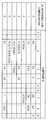
TDD의 케이스에서는, DL 데이터가 송신되는 서브프레임의 4서브프레임 후의 서브프레임이, 꼭 UL 서브프레임이라고는 할 수 없다. 그 때문에, TDD의 UL/DL 컨피규레이션마다, DL 데이터가 송신되는 DL 서브프레임과, 당해 DL 데이터에 관한 ACK/NACK가 송신되는 UL 서브프레임의 대응이, 3GPP(Third Generation Partnership Project) TS36.213 Table 10.1.3.1-1에서 규정되어 있다. 이하, 도 4를 참조하여, TDD의 UL/DL 컨피규레이션의 예를 설명한다.In the case of TDD, a subframe after four subframes of a subframe in which DL data is transmitted is not necessarily an UL subframe. For this reason, the correspondence between the DL subframe in which DL data is transmitted and the UL subframe in which ACK / NACK is transmitted with respect to the DL data for each UL / DL configuration of TDD is determined by the 3GPP (Third Generation Partnership Project) TS36.213 Table It is specified in 10.1.3.1-1. Hereinafter, an example of the UL / DL configuration of the TDD will be described with reference to FIG.
도 4는, TDD의 UL/DL 컨피규레이션의 예를 설명하기 위한 설명도이다. 도 4를 참조하면, TDD의 UL/DL 컨피규레이션으로서, 컨피규레이션 0 내지 6이 도시되어 있다. 이와 같이, TDD에서는, 컨피규레이션에 따라 UL 서브프레임 및 DL 서브프레임의 수 및 배치가 상이하다. 또한, 컨피규레이션 0 내지 6은 3GPP TS 36.211에 포함되는 Table 4.2-2에 나타나 있는 것과 동일하다.4 is an explanatory view for explaining an example of the UL / DL configuration of the TDD. Referring to FIG. 4,
<<2. 시스템의 개략적인 구성>><< 2. Schematic configuration of the system >>
계속해서, 도 5 내지 도 7을 참조하여, 본 개시의 실시 형태에 따른 시스템(1)의 개략적인 구성을 설명한다. 도 5는, 본 실시 형태에 따른 시스템(1)의 개략적인 구성의 일례를 도시하는 설명도이다. 도 5를 참조하면, 시스템(1)은 기지국(100) 및 단말 장치(200)를 포함한다.Next, a schematic configuration of the
(1) 기지국(100)(1)
기지국(100)은 이동체 통신 시스템(또는 셀룰러 시스템)의 기지국이다. 일례로서, 당해 이동체 통신 시스템은, LTE, LTE-Advanced, 또는 이들에 준하는 통신 규격에 준거한 시스템이다. 기지국(100)은 FDD를 서포트하고, FDD의 DL 대역 및 UL 대역을 사용하고, (셀(101) 내에 위치하는) 단말 장치와의 무선 통신을 행한다. 예를 들어, 상기 UL 대역은, UL의 컴포넌트 캐리어(CC)이며, 상기 DL 대역은, DL의 CC이다.The
특히, 기지국(100)은 상기 UL 대역이 UL에 사용되는 제1 모드와, 상기 UL 대역이 시분할에 의해 DL 및 UL의 양쪽에 사용되는 제2 모드 사이에서, 상기 UL 대역에 관한 동작 모드를 전환한다.In particular, the
예를 들어, 상기 동작 모드가 상기 제1 모드인 경우에는, 기지국(100)은 상기 DL 대역에서 단말 장치로의 DL 신호를 송신하고, 상기 UL 대역에서 단말 장치로부터의 UL 신호를 수신한다.For example, when the operation mode is the first mode, the
예를 들어, 상기 동작 모드가 상기 제2 모드인 경우에는, 기지국(100)은 상기 DL 대역에서 단말 장치로의 DL 신호를 송신하고, 또한, 상기 UL 대역에서 DL 서브프레임에서 단말 장치로의 DL 신호를 송신한다. 또한, 기지국(100)은 상기 UL 대역에서 UL 서브프레임에서 단말 장치로부터의 UL 신호를 수신한다.For example, when the operation mode is the second mode, the
(2) 단말 장치(200)(2) The
단말 장치(200)는 상기 이동체 통신 시스템(또는 셀룰러 시스템)에 있어서 통신 가능한 단말 장치이다. 특히, 기지국(100)은 상기 제2 모드를 서포트한다.The
예를 들어, 상기 동작 모드가 상기 제1 모드인 경우에는, 단말 장치(200)는 상기 DL 대역에서 기지국(100)으로부터의 DL 신호를 수신하고, 상기 UL 대역에서 기지국(100)으로의 UL 신호를 송신한다.For example, when the operation mode is the first mode, the
예를 들어, 상기 동작 모드가 상기 제2 모드인 경우에는, 단말 장치(200)는 상기 DL 대역에서 기지국(100)으로부터의 DL 신호를 수신하고, 또한, 상기 UL 대역에서 DL 서브프레임에서 기지국(100)으로부터의 DL 신호를 수신한다. 또한, 단말 장치(200)는 상기 UL 대역에서 UL 서브프레임에서 기지국(100)으로의 UL 신호를 송신한다.For example, when the operation mode is the second mode, the
(3) HetNet(3) HetNet
(a) 매크로셀의 케이스(a) Case of Macrocell
예를 들어, 기지국(100)은 매크로셀의 기지국이다. 즉, 셀(101)은 매크로셀이다. 이하, 이 점에 대하여 도 6을 참조하여, 구체예를 설명한다.For example, the
도 6은, 기지국(100)이 매크로셀의 기지국인 케이스를 설명하기 위한 설명도이다. 도 6을 참조하면, 기지국(100) 및 단말 장치(200)가 도시되어 있다. 이 예에서는, 기지국(100)은 매크로셀의 기지국이며, 셀(101)은 스몰셀(21)과 겹치는 매크로셀이다. 예를 들어, 단말 장치(200)는 스몰셀(21) 내에 위치하는 경우에, 스몰셀(21)의 기지국(20)과의 무선 통신을 행하는 것이 가능하다.6 is an explanatory diagram for explaining a case in which the
(b) 스몰셀의 케이스(b) Case of small cell
기지국(100)은 스몰셀의 기지국이어도 된다. 즉, 셀(101)은 스몰셀이어도 된다. 이하, 이 점에 대하여 도 7을 참조하여, 구체예를 설명한다.The
도 7은, 기지국(100)이 스몰셀의 기지국인 케이스를 설명하기 위한 설명도이다. 도 7을 참조하면, 기지국(100) 및 단말 장치(200)가 도시되어 있다. 이 예에서는, 기지국(100)은 스몰셀의 기지국이며, 셀(101)은 매크로셀(31)과 겹치는 스몰셀이다. 예를 들어, 단말 장치(200)는 매크로셀(31) 내에 위치하는 경우에, 매크로셀(31)의 기지국(30)과의 무선 통신을 행하는 것이 가능하다.7 is an explanatory diagram for explaining a case in which the
<<3. 각 장치의 구성>><< 3. Configuration of each device >>
계속해서, 도 8 내지 도 10을 참조하여, 본 개시의 실시 형태에 따른 기지국(100) 및 단말 장치(200)의 구성을 설명한다Next, the configuration of the
<3.1. 기지국의 구성>3.1. Base Station Configuration>
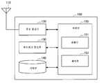
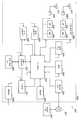
먼저, 도 8을 참조하여, 본 개시의 실시 형태에 따른 기지국(100)의 구성의 일례를 설명한다. 도 8은, 본 개시의 실시 형태에 따른 기지국(100)의 구성의 일례를 도시하는 블록도이다. 도 8을 참조하면, 기지국(100)은 안테나부(110), 무선 통신부(120), 네트워크 통신부(130), 기억부(140) 및 처리부(150)를 구비한다.First, an example of the configuration of the
(1) 안테나부(110)(1) An
안테나부(110)는 무선 통신부(120)에 의해 출력되는 신호를 전파로서 공간에 방사한다. 또한, 안테나부(110)는 공간의 전파를 신호로 변환하고, 당해 신호를 무선 통신부(120)로 출력한다.The
(2) 무선 통신부(120)(2) The
무선 통신부(120)는 신호를 송수신한다. 예를 들어, 무선 통신부(120)는 단말 장치로의 DL 신호를 송신하고, 단말 장치로부터의 UL 신호를 수신한다.The
(3) 네트워크 통신부(130)(3)
네트워크 통신부(130)는 정보를 송수신한다. 예를 들어, 네트워크 통신부(130)는 다른 노드로의 정보를 송신하고, 다른 노드로부터의 정보를 수신한다. 예를 들어, 상기 다른 노드는, 다른 기지국 및 코어 네트워크 노드를 포함한다.The
(4) 기억부(140)(4) Storage unit 140 [
기억부(140)는 기지국(100)의 동작을 위한 프로그램 및 여러가지 데이터를 일시적으로 또는 항구적으로 기억한다.The
(5) 처리부(150)(5)
처리부(150)는 기지국(100)의 여러가지 기능을 제공한다. 처리부(150)는 전환부(151) 및 제어부(153)를 포함한다. 또한, 처리부(150)는 이들 구성 요소 이외의 다른 구성 요소를 더 포함할 수 있다. 즉, 처리부(150)는 이들 구성 요소의 동작 이외의 동작도 행할 수 있다.The
전환부(151) 및 제어부(153)는 나중에 상세하게 설명한다.The
<3.2. 단말 장치의 구성><3.2. Configuration of terminal device>
먼저, 도 9 및 도 10을 참조하여, 본 개시의 실시 형태에 따른 단말 장치(200)의 구성의 일례를 설명한다. 도 9는, 본 개시의 실시 형태에 따른 단말 장치(200)의 구성의 일례를 도시하는 블록도이다. 도 9를 참조하면, 단말 장치(200)는 안테나부(210), 무선 통신부(220), 기억부(230) 및 처리부(240)를 구비한다.First, an example of the configuration of the
(1) 안테나부(210)(1)
안테나부(210)는 무선 통신부(220)에 의해 출력되는 신호를 전파로서 공간에 방사한다. 또한, 안테나부(210)는 공간의 전파를 신호로 변환하고, 당해 신호를 무선 통신부(220)로 출력한다.The
(2) 무선 통신부(220)(2) the
무선 통신부(220)는 신호를 송수신한다. 예를 들어, 무선 통신부(220)는 기지국으로부터의 DL 신호를 수신하고, 기지국으로의 UL 신호를 송신한다. 이하, 도 10을 참조하여, 무선 통신부(220)에 포함되는 하드웨어의 일례를 설명한다.The
도 10은, 본 개시의 실시 형태에 따른 단말 장치(200)의 무선 통신부(220)에 포함되는 하드웨어의 일례를 설명하기 위한 설명도이다. 도 10을 참조하면, 무선 통신부(220)에 포함되는 FDD-DL 수신 회로(221), FDD-UL 송신 회로(223), TDD-DL 수신 회로(225)가 도시되어 있다. 또한, FDD의 UL 대역을 위한 국부 발진기(local oscillator)(227), 및 FDD의 DL 대역을 위한 국부 발진기(229)도 도시되어 있다. 또한, 안테나부(210)에 포함되는 안테나(211)도 도시되어 있다. 예를 들어, UL 대역에 관한 동작 모드가, 상기 UL 대역이 UL에 사용되는 제1 모드인 경우에는, FDD-DL 수신 회로(221) 및 FDD-UL 송신 회로(223)가 사용된다. 예를 들어, 상기 동작 모드가, 상기 UL 대역이 시분할에 의해 DL 및 UL의 양쪽에 사용되는 제2 모드인 경우에는, FDD-DL 수신 회로(221) 및 FDD-UL 송신 회로(223)에 추가로, TDD-DL 수신 회로(225)가 사용된다. 보다 구체적으로, 시분할로, FDD-UL 송신 회로(223) 및 TDD-DL 수신 회로(225)가 사용된다.10 is an explanatory view for explaining an example of hardware included in the
(3) 기억부(230)(3)
기억부(230)는 단말 장치(200)의 동작을 위한 프로그램 및 여러가지 데이터를 일시적으로 또는 항구적으로 기억한다.The
(4) 처리부(240)(4)
처리부(240)는 단말 장치(200)의 여러가지 기능을 제공한다. 처리부(240)는 정보 취득부(241) 및 제어부(243)를 포함한다. 또한, 처리부(240)는 이들 구성 요소 이외의 다른 구성 요소를 더 포함할 수 있다. 즉, 처리부(240)는 이들 구성 요소의 동작 이외의 동작도 행할 수 있다.The
정보 취득부(241) 및 제어부(243)는 나중에 상세하게 설명한다.The
<<4. 제1 실시 형태>><< 4. First Embodiment >
계속해서, 도 11 내지 도 14를 참조하여, 본 개시의 제1 실시 형태를 설명한다.Next, a first embodiment of the present disclosure will be described with reference to Figs. 11 to 14. Fig.
<4.1. 기술적 과제><4.1. Technical challenges>
먼저, 도 11을 참조하여, 제1 실시 형태에 따른 기술적 과제를 설명한다.First, the technical problem according to the first embodiment will be described with reference to FIG.
FDD의 UL 대역을 시분할로 DL 및 UL의 양쪽에 사용하는 방법이 검토되고 있다. 당해 방법은, 플렉시블 듀플렉스라고 불릴 수 있다.A method of using the UL band of FDD in both DL and UL by time division has been studied. This method can be called a flexible duplex.
그러나, FDD의 UL 대역을 시분할로 DL 및 UL의 양쪽에 사용하는 경우에는, 당해 UL 대역에서 무선 통신이 양호하게 행하여지지 않을 가능성이 있다.However, when the UL band of the FDD is used for both DL and UL in a time-division manner, there is a possibility that wireless communication in the UL band is not performed well.
보다 구체적으로는, 예를 들어, UL 대역에서의 UL로부터 DL로의 전환에 기인하여 당해 UL 대역에 관한 DL 송신 타이밍이 지연된다. 그 결과, FDD의 DL 대역에 관한 DL 송신 타이밍과, 상기 UL 대역에 관한 DL 송신의 타이밍 사이에 어긋남이 발생할 수 있다. 그 때문에, 상기 DL 대역에 관한 DL 수신 타이밍을 기준으로 하여 조정된 UL 송신 타이밍과, 상기 UL 대역에 관한 DL 수신 타이밍을 기준으로 하여 조정된 UL 송신 타이밍은, 상이할 수 있다. 따라서, 기지국에 있어서의 UL 수신 타이밍의 동기가 실현되지 않을 가능성이 있다. 이하, 이 점에 대하여 도 11을 참조하여 전환에 기인하는 DL 송신 타이밍의 지연의 구체예를 설명한다.More specifically, for example, the DL transmission timing for the UL band is delayed due to the transition from UL to DL in the UL band. As a result, a discrepancy may occur between the DL transmission timing of the DL band of the FDD and the DL transmission timing of the UL band. Therefore, the UL transmission timing adjusted based on the DL reception timing for the DL band and the UL transmission timing adjusted based on the DL reception timing for the UL band may be different. Therefore, there is a possibility that synchronization of the UL reception timing at the base station may not be realized. Hereinafter, a specific example of the delay of the DL transmission timing due to switching will be described with reference to Fig.
도 11은, UL 대역에서의 UL과 DL의 전환에 기인하는 DL 송신 타이밍의 지연의 일례를 설명하기 위한 설명도이다. 도 11을 참조하면, FDD의 UL 대역이 UL에 사용되는 제1 모드에서의 기지국에 있어서의 송수신 타이밍과, 당해 UL 대역이 시분할에 의해 DL 및 UL의 양쪽에 사용되는 제2 모드에서의 당해 기지국에 있어서의 송수신 타이밍이 도시되어 있다. 예를 들어, 상기 제1 모드에서는, 상기 기지국에 있어서 DL 송신 타이밍과 UL 수신 타이밍이 동기하고 있다. 한편, 상기 제2 모드에서는, 상기 UL 대역에서의 UL로부터 DL로의 전환에 시간(81)을 필요로 하기 때문에, 상기 기지국에 있어서, 당해 UL 대역에 관한 DL 송신 타이밍이, 상기 DL 대역에 관한 DL 송신 타이밍보다도 지연된다. 그 결과, 단말 장치에서도, 상기 UL 대역에 관한 DL 수신 타이밍이, 상기 DL 대역에 관한 DL 수신 타이밍보다도 지연된다. 그 때문에, 상기 DL 대역에 관한 상기 DL 수신 타이밍을 기준으로 하여 조정되는 UL 송신 타이밍과, 상기 UL 대역에 관한 상기 DL 수신 타이밍을 기준으로 하여 조정되는 UL 송신 타이밍이 상이하다. 따라서, 기지국에 있어서의 UL 수신 타이밍의 동기가 실현되지 않을 가능성이 있다.11 is an explanatory view for explaining an example of the delay of the DL transmission timing due to the switching of UL and DL in the UL band. 11, the transmission / reception timing of the base station in the first mode in which the UL band of the FDD is used in the UL and the transmission / reception timing of the base station in the second mode in which the UL band is used in both DL and UL by time- Reception timing at the time of transmission. For example, in the first mode, the DL transmission timing and the UL reception timing are synchronized with each other in the base station. On the other hand, in the second mode,
따라서, FDD의 UL 대역을 시분할로 DL 및 UL의 양쪽에 사용하는 경우에 당해 UL 대역에서 보다 양호하게 무선 통신을 행하는 것을 가능하게 하는 구조가 제공되는 것이 바람직하다. 보다 구체적으로는, 예를 들어, FDD의 UL 대역을 시분할로 DL 및 UL의 양쪽에 사용하는 경우에 기지국에 있어서의 UL 수신 타이밍의 동기를 실현하는 것을 가능하게 하는 구조가 제공되는 것이 바람직하다.Therefore, it is desirable to provide a structure that enables wireless communication to be performed better in the UL band when the UL band of the FDD is used in both DL and UL in a time division manner. More specifically, for example, it is desirable to provide a structure that enables synchronization of UL reception timing at the base station when the UL band of the FDD is used for both DL and UL in a time-division manner.
<4.2. 기술적 특징>4.2. Technical Features>
이어서, 도 12를 참조하여, 제1 실시 형태에 따른 기술적 특징을 설명한다.Next, the technical features according to the first embodiment will be described with reference to Fig.
(1) 동작 모드의 전환(1) Switching of operation mode
기지국(100)(전환부(151))은 FDD의 UL 대역이 UL에 사용되는 제1 모드와, 상기 UL 대역이 시분할에 의해 DL 및 UL의 양쪽에 사용되는 제2 모드 사이에서, 상기 UL 대역에 관한 동작 모드를 전환한다.The base station 100 (switching unit 151) is configured to switch between a first mode in which the UL band of FDD is used for UL and a second mode in which the UL band is used for both DL and UL by time division, The operation mode is switched.
(a) 전환의 트리거(a) triggers the transition
예를 들어, 셀(101)에 있어서 DL의 트래픽이 UL의 트래픽보다도 충분히 커지고, 또한, 상기 제2 모드를 서포트하는 단말 장치의 수가 충분하면, 기지국(100)(전환부(151))은 상기 UL 대역에 관한 상기 동작 모드를, 상기 제1 모드로부터 상기 제2 모드로 전환한다.For example, when the DL traffic in the
(b) 전환 전후에서의 UL 송신 타이밍(b) UL transmission timing before and after switching
예를 들어, 기지국(100)은 상기 UL 대역에 관한 상기 동작 모드의 전환 전후에, UL 송신 타이밍(환언하면, UL 프레임 타이밍)을 변경하지 않는다. 이에 의해, 예를 들어, 상기 제2 모드를 서포트하지 않는 단말 장치(이하, 「레거시 단말기」라 칭한다)에 대한 영향을 보다 작게 하는 것이 가능해진다.For example, the
또한, 상기 제2 모드에서는, 상기 UL 대역에 관한 DL 송신 타이밍은, 상기 동작 모드의 전환에 기인하는 지연의 분만큼, 상기 UL 대역에 대응하는 FDD의 DL 대역에 관한 DL 송신 타이밍보다도 느려진다. 이 점에 대해서는, 도 11을 참조하여 설명한 바와 같다.Further, in the second mode, the DL transmission timing with respect to the UL band is slower than the DL transmission timing with respect to the DL band of the FDD corresponding to the UL band, corresponding to the delay caused by the switching of the operation mode. This point is as described with reference to Fig.
(c) 전환의 통지(c) Notice of Conversion
예를 들어, 기지국(100)(제어부(153))은 상기 제1 모드와 상기 제2 모드 사이에서의 상기 동작 모드의 전환을 나타내는 정보(이하, 「모드 전환 정보」라 칭한다)를 단말 장치(200)에 통지한다.For example, the base station 100 (the control unit 153) transmits information (hereinafter referred to as "mode switching information") indicating the switching of the operation mode between the first mode and the second mode to the terminal apparatus 200).
구체적으로는, 예를 들어, 기지국(100)(제어부(153))은 시스템 정보(System Information) 중에서, 상기 모드 전환 정보를 단말 장치(200)에 통지한다. 또는, 기지국(100)(제어부(153))은 단말 장치(200)로의 개별의 시그널링에 의해, 상기 모드 전환 정보를 단말 장치(200)에 통지해도 된다. 예를 들어, 당해 개별의 시그널링은, RRC(Radio Resource Control) 시그널링이어도 된다.Specifically, for example, the base station 100 (the control unit 153) notifies the
(d) 전환에 따른 단말 장치(200)의 동작(d) Operation of the
단말 장치(200)(정보 취득부(241))는 상기 모드 전환 정보를 취득한다. 단말 장치(200)는 상기 동작 모드가 상기 제1 모드인 경우에, 상기 UL 대역에서 UL 송신을 행하고, 상기 동작 모드가 상기 제2 모드인 경우에, 상기 UL 대역에서 DL 수신 및 UL 송신을 행한다.The terminal device 200 (information acquisition unit 241) acquires the mode switching information. The
단말 장치(200)의 제어부(243)는 상기 동작 모드가 상기 제1 모드인 경우에, 상기 UL 대역에서의 UL 송신을 위한 처리를 행하고, 상기 동작 모드가 상기 제2 모드인 경우에, 상기 UL 대역에서의 DL 수신 및 UL 송신을 위한 처리를 행한다.The
(2) 타이밍 어드밴스에 관한 지시(2) Instruction on timing advance
제1 실시 형태에서는, 기지국(100)(제어부(153))은 상기 DL 대역에 관한 DL 수신 타이밍을 기준으로 하는 제1 타이밍 어드밴스(timing advance: TA)에 관한 지시, 및 상기 UL 대역에 관한 DL 수신 타이밍을 기준으로 하는 제2 TA에 관한 지시를 행한다.In the first embodiment, the base station 100 (control unit 153) receives an instruction regarding a first timing advance (TA) based on the DL reception timing with respect to the DL band, And makes an instruction regarding the second TA based on the reception timing.
특히 제1 실시 형태에서는, 상기 제1 TA에 관한 상기 지시, 및 상기 제2 TA에 관한 상기 지시는, 상기 제2 모드를 서포트하는 동일한 단말 장치(200)로의 지시이다.In particular, in the first embodiment, the instruction on the first TA and the instruction on the second TA are instructions to the same
한편, 단말 장치(200)(제어부(243))는 상기 동작 모드가 상기 제2 모드인 경우에, 상기 DL 대역에 관한 DL 수신 타이밍과, 상기 제1 TA를 나타내는 정보에 기초하여, 상기 UL 대역에 관한 UL 송신 타이밍을 조정한다. 또는, 단말 장치(200)(제어부(243))는 상기 동작 모드가 상기 제2 모드인 경우에, 상기 UL 대역에 관한 DL 수신 타이밍과, 상기 제2 TA를 나타내는 정보에 기초하여, 상기 UL 대역에 관한 UL 송신 타이밍을 조정한다.On the other hand, when the operation mode is the second mode, the terminal apparatus 200 (the control section 243) determines, based on the DL reception timing regarding the DL band and the information indicating the first TA, In the UL transmission timing. Alternatively, when the operation mode is the second mode, the terminal device 200 (the control section 243) may determine whether or not the UL band is in the UL band based on the DL reception timing relating to the UL band and the information indicating the second TA In the UL transmission timing.
(a) 제2 모드에서의 지시(a) instructions in the second mode
예를 들어, 기지국(100)(제어부(153))은 상기 동작 모드가 상기 제2 모드인 경우에, 상기 제1 TA에 관한 상기 지시, 및 상기 제2 TA에 관한 상기 지시를 행한다.For example, the base station 100 (control unit 153) performs the above-mentioned instruction about the first TA and the above-mentioned instruction about the second TA when the operation mode is the second mode.
(b) 제1 TA 및 제2 TA(b) The first TA and the second TA
예를 들어, 상기 제2 TA는, 상기 제1 TA보다도 길다. 이하, 도 12를 참조하여, 상기 제1 TA 및 상기 제2 TA의 구체예를 설명한다.For example, the second TA is longer than the first TA. Hereinafter, specific examples of the first TA and the second TA will be described with reference to FIG.
도 12는, 제1 TA 및 제2 TA의 예를 설명하기 위한 설명도이다. 도 12를 참조하면, UL 대역에 관한 동작 모드가 제2 모드인 경우에 있어서의 기지국(100) 및 단말 장치(200)의 송수신 타이밍이 도시되어 있다. 기지국(100)에서는, UL 대역에서의 UL로부터 DL로의 전환에 시간(41)을 필요로 하기 때문에, 당해 UL 대역에 관한 DL 송신 타이밍이, DL 대역에 관한 DL 송신 타이밍보다도 지연된다. 그 결과, 단말 장치(200)에서도, 상기 UL 대역에 관한 DL 수신 타이밍이, 상기 DL 대역에 관한 DL 수신 타이밍보다도 지연된다. 그 때문에, 기지국(100)(제어부(153))은 상기 DL 대역에 관한 DL 수신 타이밍을 기준으로 하는 제1 TA(43)에 관한 지시와, 상기 UL 대역에 관한 DL 수신 타이밍을 기준으로 하는 제2 TA(45)에 관한 지시를 행한다. 제2 TA(45)는, 제1 TA(43)보다도 길다. 단말 장치(200)(제어부(243))는 상기 DL 대역에 관한 DL 수신 타이밍과, 제1 TA(43)를 나타내는 정보에 기초하여, 상기 UL 대역에서의 UL 송신 타이밍을 조정한다. 또는, 단말 장치(200)(제어부(243))는 상기 UL 대역에 관한 DL 수신 타이밍과, 제2 TA(45)를 나타내는 정보에 기초하여, 상기 UL 대역에서의 UL 송신 타이밍을 조정한다.12 is an explanatory view for explaining examples of the first TA and the second TA. Referring to FIG. 12, transmission / reception timings of the
(c) 지시의 방법(c) Method of instruction
(c-1) 타이밍 어드밴스 커맨드의 통지(c-1) Notification of the timing advance command
예를 들어, 기지국(100)(제어부(153))은 타이밍 어드밴스(TA) 커맨드의 통지에 의해, 상기 제1 TA에 관한 상기 지시, 및 상기 제2 TA에 관한 상기 지시를 행한다.For example, the base station 100 (the control unit 153) makes the above instruction about the first TA and the instruction about the second TA by the notification of the timing advance (TA) command.
―개개의 TA 커맨드- Individual TA commands
예를 들어, 상기 TA 커맨드는, 상기 제1 TA를 위한 TA 커맨드와, 상기 제2 TA를 위한 TA 커맨드를 포함한다. 즉, 기지국(100)(제어부(153))은 상기 제1 TA를 위한 TA 커맨드의 통지에 의해, 상기 제1 TA에 관한 지시를 행하고, 상기 제2 TA를 위한 TA 커맨드의 통지에 의해, 상기 제2 TA에 관한 지시를 행한다.For example, the TA command includes a TA command for the first TA and a TA command for the second TA. That is, the base station 100 (the control unit 153) instructs the first TA by the notification of the TA command for the first TA, and upon notification of the TA command for the second TA, And makes an instruction regarding the second TA.
예를 들어, 단말 장치(200)(제어부(243))는 상기 제1 TA를 위한 상기 TA 커맨드에 기초하여, 상기 제1 TA를 나타내는 정보를 생성하고, 상기 제2 TA를 위한 상기 TA 커맨드에 기초하여, 상기 제2 TA를 나타내는 정보를 생성한다.For example, the terminal apparatus 200 (the control section 243) generates information indicating the first TA based on the TA command for the first TA, and generates the TA command for the second TA , Generates information indicating the second TA.
구체적으로는, 예를 들어, 기지국(100)(제어부(153))은 상기 제1 TA를 조정하기 위한 TA1을 나타내는 TA 커맨드를 단말 장치(200)에 통지한다. 또한, 기지국(100)(제어부(153))은 상기 제2 TA를 조정하기 위한 TA2를 나타내는 TA 커맨드를 단말 장치(200)에 통지한다. 예를 들어, 단말 장치(200)는 TA1으로부터, 상기 제1 TA에 관한 NTA1을 산출한다. 즉, 단말 장치(200)는 상기 제1 TA를 나타내는 정보인 NTA1을 생성한다. 그리고, 단말 장치(200)는 상기 DL 대역에 관한 DL 수신 타이밍과 NTA1에 기초하여, 상기 UL 대역에 관한 UL 송신 타이밍을 조정한다. 또는, 단말 장치(200)는 TA2로부터, 상기 제2 TA에 관한 NTA2를 산출한다. 즉, 단말 장치(200)는 상기 제2 TA를 나타내는 정보인 NTA2를 생성한다. 그리고, 단말 장치(200)는 상기 UL 대역에 관한 DL 수신 타이밍과 NTA2에 기초하여, 상기 UL 대역에 관한 UL 송신 타이밍을 조정한다.Specifically, for example, the base station 100 (the control unit 153) notifies the
이에 의해, 예를 들어, 2개의 TA를 따로따로 갱신하는 것이 가능해진다. 그 때문에, 단말 장치(200)는 DL 대역에 관한 DL 수신 타이밍, 및 상기 UL에 관한 DL 수신 타이밍 중 어디에 기초하더라도, 상기 UL 대역에 관한 UL 송신 타이밍을 적절하게 조정하는 것이 가능해진다. 또한, 상기 UL 대역과는 지연 분산이 상이한 상기 DL 대역에서의 DL 수신 타이밍이 아니라, 상기 UL 대역에서의 DL 수신 타이밍에 기초하여, 상기 UL 대역에서의 UL 송신 타이밍을 조정함으로써, 보다 높은 정밀도의 타이밍 조정이 가능해진다.Thus, for example, it is possible to update two TAs separately. Therefore, the
―타이밍 어드밴스 그룹(TAG)- Timing advance group (TAG)
예를 들어, 상기 제1 TA를 위한 상기 TA 커맨드는, 제1 TAG를 위한 커맨드이며, 상기 제2 TA를 위한 상기 TA 커맨드는, 상기 제1 TAG와는 다른 제2 TAG를 위한 커맨드이다.For example, the TA command for the first TA is a command for a first TAG, and the TA command for the second TA is a command for a second TAG different from the first TAG.
구체적으로는, 예를 들어, 기지국(100)은 상기 제1 TA를 위한 TA 커맨드와 상기 제1 TAG의 TAG ID를 포함하는 MAC 컨트롤 엘리먼트를, 단말 장치(200)로 송신한다. 또한, 기지국(100)은 상기 제2 TA를 위한 TA 커맨드와 상기 제2 TAG의 TAG ID를 포함하는 MAC 컨트롤 엘리먼트를, 단말 장치(200)로 송신한다.Specifically, for example, the
이에 의해, 예를 들어, 단말 장치(200)는 상기 제1 TA를 위한 TA 커맨드와, 상기 제2 TA를 위한 TA 커맨드를 구별하는 것이 가능해진다.Thus, for example, the
(c-2) 오프셋의 통지(c-2) Notification of Offset
기지국(100)(제어부(153))은 TA 커맨드의 통지에 의해, 상기 제1 TA 및 상기 제2 TA 중 한쪽에 관한 지시를 행하고, 상기 제1 TA와 상기 제2 TA 사이의 오프셋을 나타내는 정보(이하, 「오프셋 정보」라 칭한다)의 통지에 의해, 상기 제1 TA 및 상기 제2 TA 중 다른 쪽에 관한 지시를 행해도 된다.The base station 100 (control unit 153) issues an instruction regarding one of the first TA and the second TA by notification of the TA command, and transmits information indicating an offset between the first TA and the second TA (Hereinafter, referred to as " offset information "), the instruction regarding the other of the first TA and the second TA may be performed.
단말 장치(200)(제어부(243))는 상기 TA 커맨드에 기초하여, 상기 제1 TA 및 상기 제2 TA 중 상기 한쪽을 나타내는 정보를 생성하고, 당해 정보와 상기 오프셋 정보에 기초하여, 상기 제1 TA 및 상기 제2 TA 중 상기 다른 쪽을 나타내는 정보를 생성해도 된다.The terminal device 200 (control section 243) generates information indicating the one of the first TA and the second TA based on the TA command, and based on the information and the offset information, 1 TA and the second TA.
상기 제1 TA 및 상기 제2 TA 중 한쪽은, 상기 제1 TA이며, 상기 제1 TA 및 상기 제2 TA 중 다른 쪽은, 상기 제2 TA여도 된다.One of the first TA and the second TA is the first TA and the other of the first TA and the second TA is the second TA.
―구체적인 예- Specific examples
구체적으로는, 기지국(100)(제어부(153))은 상기 제1 TA를 조정하기 위한 TA1을 나타내는 TA 커맨드를 단말 장치(200)에 통지해도 된다. 단말 장치(200)는 TA1으로부터, 상기 제1 TA에 관한 NTA1을 산출해도 된다. 즉, 단말 장치(200)는 상기 제1 TA를 나타내는 정보인 NTA1을 생성해도 된다. 또한, 기지국(100)(제어부(153))은, (예를 들어, 시스템 정보 중에서, 또는 시그널링에 의해,) 상기 제1 TA와 상기 제2 TA 사이의 오프셋을 나타내는 정보(오프셋 정보)인 NTA_offset를 단말 장치(200)에 통지해도 된다. 단말 장치(200)는 NTA1과 NTA_offset으로부터, NTA2(예를 들어, NTA1+NTA_offset)를 산출해도 된다. 즉, 단말 장치(200)는 상기 제2 TA를 나타내는 정보인 NTA2를 생성해도 된다. 또한, NTA_offset는, 소정값(예를 들어, 624)이어도 된다.Specifically, the base station 100 (the control unit 153) may notify the
―오프셋의 사용 방법- How to use offset
――동작 모드의 전환 시의 사용- Use when switching operation mode
단말 장치(200)는 상기 UL 대역의 상기 동작 모드가 상기 제1 모드로부터 상기 제2 모드로 전환되는 때에, 상기 제1 TA를 나타내는 상기 정보(예를 들어, NTA1)와, 상기 오프셋 정보(예를 들어, NTA_offset)로부터, 상기 제2 TA를 나타내는 상기 정보(예를 들어, NTA2)를 초기값으로서 생성해도 된다. 그 후, 단말 장치(200)는 상기 제2 TA 커맨드에 기초하여, 상기 제2 TA를 나타내는 상기 정보(예를 들어, NTA2)를 생성(갱신)해도 된다.When the operation mode of the UL band is switched from the first mode to the second mode, the
――계속적인 사용- Continuous use
또는, 단말 장치(200)는 계속적으로, 상기 제1 TA를 나타내는 상기 정보(예를 들어, NTA1)와, 상기 오프셋 정보(예를 들어, NTA_offset)로부터, 상기 제2 TA를 나타내는 상기 정보(예를 들어, NTA2)를 생성해도 된다.Alternatively, the
―통지의 예- Examples of notifications
――통지의 방법- Method of notification
기지국(100)(제어부(153))은 시스템 정보 중에서, 상기 오프셋 정보의 통지를 행해도 된다. 또는, 기지국(100)(제어부(153))은 시그널링에 의해, 상기 오프셋 정보의 통지를 행해도 된다.The base station 100 (the control unit 153) may notify of the offset information among the system information. Alternatively, the base station 100 (the control unit 153) may notify the offset information by signaling.
――통지의 타이밍- Timing of notification
기지국(100)(제어부(153))은 상기 동작 모드가 상기 제2 동작 모드인 경우에 한하지 않고, 상기 동작 모드가 상기 제1 모드인 경우에, 상기 오프셋 정보의 통지를 행해도 된다. 즉, 기지국(100)(제어부(153))은 상기 동작 모드가 상기 제2 동작 모드인 경우에 한하지 않고, 상기 동작 모드가 상기 제1 모드인 경우에, 상기 제2 TA에 관한 상기 지시를 행해도 된다.The base station 100 (control unit 153) may notify the offset information only when the operation mode is the second operation mode, and when the operation mode is the first mode. That is, the base station 100 (the control unit 153) is not limited to the case where the operation mode is the second operation mode, and when the operation mode is the first mode, You can do it.
―기타-Other
기지국(100)이 상기 오프셋 정보(예를 들어, NTA_offset)를 단말 장치(200)에 통지하는 대신, 상기 오프셋 정보가 단말 장치(200)에 있어서 미리 기억되어 있어도 된다.The offset information may be previously stored in the
(d) 단말 장치(200)에 있어서의 타이밍 조정 방법의 선택(d) Selection of a timing adjustment method in the
(d-1) UL 데이터(d-1) UL data
예를 들어, 기지국(100)이 상기 DL 대역에서, UL 데이터의 스케줄링 정보를 단말 장치(200)로 송신한다. 이 경우에, 예를 들어, 단말 장치(200)(제어부(243))는 상기 UL 데이터의 송신을 위해서, 상기 DL 대역에 관한 DL 수신 타이밍과, 상기 제1 TA를 나타내는 상기 정보에 기초하여, 상기 UL 대역에 관한 UL 송신 타이밍을 조정한다.For example, the
예를 들어, 기지국(100)이 상기 UL 영역에 있어서, DL 서브프레임에서, UL 데이터의 스케줄링 정보를 단말 장치(200)로 송신한다. 이 경우에, 예를 들어, 단말 장치(200)(제어부(243))는 상기 UL 데이터의 송신을 위해서, 상기 UL 대역에 관한 DL 수신 타이밍과, 상기 제2 TA를 나타내는 상기 정보에 기초하여, 상기 UL 대역에 관한 UL 송신 타이밍을 조정한다.For example, the
(d-2) ACK/NACK(d-2) ACK / NACK
예를 들어, 단말 장치(200)(제어부(243))는 상기 DL 대역에서 송신된 DL 데이터에 관한 ACK/NACK의 송신을 위해서, 상기 DL 대역에 관한 DL 수신 타이밍과, 상기 제1 TA를 나타내는 상기 정보에 기초하여, 상기 UL 대역에 관한 UL 송신 타이밍을 조정한다.For example, the terminal apparatus 200 (the control section 243) may be configured to transmit the DL reception timing relating to the DL band and the DL reception timing relating to the first TA to transmit ACK / NACK on the DL data transmitted in the DL band And adjusts the UL transmission timing for the UL band based on the information.
예를 들어, 단말 장치(200)(제어부(243))는 상기 UL 대역에서 송신된 DL 데이터에 관한 ACK/NACK의 송신을 위해서, 상기 UL 대역에 관한 DL 수신 타이밍과, 상기 제2 TA를 나타내는 상기 정보에 기초하여, 상기 UL 대역에 관한 UL 송신 타이밍을 조정한다.For example, the terminal apparatus 200 (the control section 243) may transmit the DL reception timing relating to the UL band and the second TA indicating the second TA for transmission of ACK / NACK with respect to the DL data transmitted in the UL band And adjusts the UL transmission timing for the UL band based on the information.
(3) 기타(3) Other
(a) UL 대역에 관한 UL/DL 컨피규레이션(a) UL / DL configuration for the UL band
예를 들어, 기지국(100)(제어부(153))은 상기 UL 대역에 관한 상기 동작 모드가 상기 제2 모드인 경우에, UL/DL 컨피규레이션에 따라서 상기 UL 대역에서의 무선 통신을 행한다.For example, the base station 100 (control unit 153) performs wireless communication in the UL band according to the UL / DL configuration when the operation mode related to the UL band is the second mode.
(a-1) UL/DL 컨피규레이션의 예(a-1) Example of UL / DL configuration
예를 들어, 상기 UL/DL 컨피규레이션은, TDD의 UL/DL 컨피규레이션이다. 보다 구체적으로는, 예를 들어, 상기 UL/DL 컨피규레이션은, 도 4에 도시되는 컨피규레이션 0 내지 6 중 어느 것이다.For example, the UL / DL configuration is a UL / DL configuration of TDD. More specifically, for example, the UL / DL configuration is any of
또한, 상기 UL/DL 컨피규레이션은, TDD의 UL/DL 컨피규레이션이 아니고, 별도의 컨피규레이션(예를 들어, FDD에 고유한 컨피규레이션)이어도 된다.In addition, the UL / DL configuration is not a UL / DL configuration of TDD, but may be a separate configuration (for example, a configuration unique to FDD).
(a-2) UL/DL 컨피규레이션의 선택(a-2) Selection of UL / DL configuration
예를 들어, 기지국(100)(제어부(153))은 상기 동작 모드가 상기 제1 모드로부터 상기 제2 모드로 전환되는 경우에, UL/DL 컨피규레이션을 선택하고, 당해 UL/DL 컨피규레이션을 상기 UL 대역에 적용한다.For example, when the operation mode is switched from the first mode to the second mode, the base station 100 (the control unit 153) selects the UL / DL configuration and transmits the UL / DL configuration to the UL Band.
예를 들어, 기지국(100)(제어부(153))은 셀(101)에 있어서의 DL의 트래픽과 UL의 트래픽에 기초하여, DL 서브프레임과 UL 서브프레임의 적절한 비율을 갖는 UL/DL 컨피규레이션을 선택한다.For example, the base station 100 (the control unit 153) may determine UL / DL configuration having an appropriate ratio of the DL subframe and the UL subframe based on the DL traffic and UL traffic in the
(a-3) UL/DL 컨피규레이션의 변경(a-3) Change of UL / DL configuration
기지국(100)(제어부(153))은 상기 동작 모드가 상기 제2 모드인 경우에, 상기 UL 대역에 관한 UL/DL 컨피규레이션을, 복수의 UL/DL 컨피규레이션 후보 중에서 변경해도 된다. 예를 들어, 기지국(100)(제어부(153))은 후술하는 제5 실시 형태와 마찬가지로, 상기 UL 대역에 관한 상기 UL/DL 컨피규레이션을 변경해도 된다.The base station 100 (the control unit 153) may change the UL / DL configuration for the UL band among a plurality of UL / DL configuration candidates when the operation mode is the second mode. For example, the base station 100 (the control unit 153) may change the UL / DL configuration for the UL band similarly to the fifth embodiment described later.
(a-4) UL/DL 컨피규레이션의 통지(a-4) Notification of UL / DL configuration
예를 들어, 기지국(100)(제어부(153))은 상기 UL 대역에 관한 UL/DL 컨피규레이션을 나타내는 정보(이하, 「컨피규레이션 정보」라 칭한다)를 단말 장치(200)에 통지한다.For example, the base station 100 (the control unit 153) notifies the
일례로서, 기지국(100)(제어부(153))은 시스템 정보 중에서, 상기 컨피규레이션 정보를 단말 장치(200)에 통지한다. 상기 컨피규레이션 정보는, 새로운 정보로서 시스템 정보 중에 포함되어도 된다. 또는, 상기 컨피규레이션 정보는, 상기 UL 대역에서 DL 서브프레임에서 송신되는 시스템 정보 중에, TDD의 UL/DL 컨피규레이션을 나타내는 정보로서 포함되어도 된다.As an example, the base station 100 (the control unit 153) notifies the
다른 예로서, 기지국(100)(제어부(153))은 단말 장치(200)로의 개별의 시그널링에 의해, 상기 컨피규레이션 정보를 단말 장치(200)에 통지한다.As another example, the base station 100 (control unit 153) notifies the
(b) 랜덤 액세스(b) random access
(b-1) 랜덤 액세스 시간 주파수 영역(b-1) a random access time frequency region
예를 들어, 기지국(100)은 SIB(System Information Block)(2) 중에서, PRACH(Physical Random Access Channel) 컨피규레이션 인덱스 및 PRACH 주파수 오프셋을 통지한다. 이에 의해, 예를 들어, 단말 장치(200)는 랜덤 액세스 프리앰블의 송신이 허가되는 무선 리소스(랜덤 액세스 시간 주파수 영역)를 아는 것이 가능해진다.For example, the
FDD에서는, 하나의 서브프레임에 대해서, 하나의 랜덤 액세스 시간 주파수 영역만이 배치된다. 무선 프레임 중 어느 서브프레임에 랜덤 액세스 시간 주파수 영역이 배치될지는, PRACH 컨피규레이션 인덱스로부터 알 수 있다. 어느 리소스 블록에 랜덤 액세스 시간 주파수 영역이 배치될지는, PRACH 주파수 오프셋으로부터 알 수 있다.In the FDD, only one random access time frequency region is allocated for one subframe. The PRACH configuration index indicates which subframe among the radio frames the random access time and frequency domain is to be allocated. It is possible to know from which PRACH frequency offset the random access time-frequency domain is allocated to which resource block.
예를 들어, 기지국(100)은 상기 UL 대역에 관한 상기 동작 모드가 상기 제2 모드인 경우에, UL 서브프레임에 랜덤 액세스 시간 주파수 영역을 배치한다.For example, the
(b-2) 랜덤 액세스 수속(b-2) Random access procedure
예를 들어, 단말 장치(200)는 아이들 상태로부터 접속 상태로의 천이를 위해서, 랜덤 액세스 시간 주파수 영역에서 랜덤 액세스 프리앰블을 송신한다.For example, the
예를 들어, 기지국(100)은 랜덤 액세스 응답을 단말 장치(200)로 송신한다. 이때에, 기지국(100)은 TA 커맨드를 단말 장치(200)에 통지한다. 예를 들어, 기지국(100)은 상기 제1 TA를 위한 TA 커맨드를 단말 장치(200)에 통지한다. 또는, 기지국(100)은 상기 제1 TA를 위한 TA 커맨드와, 상기 제2 TA를 위한 TA 커맨드를, 단말 장치(200)에 통지해도 된다.For example, the
(c) 동기 신호의 송신(c) Transmission of synchronous signal
예를 들어, 기지국(100)은 상기 UL 대역에 관한 상기 동작 모드가 상기 제2 모드인 경우에, 상기 UL 대역에서 동기 신호를 송신한다.For example, the
예를 들어, 기지국(100)의 제어부(243)는 상기 동작 모드가 상기 제2 모드인 경우에, 상기 UL 대역에서의 상기 동기 신호의 송신을 위한 처리를 행한다. 구체적으로는, 예를 들어, 제어부(243)는 상기 동기 신호의 생성, 및/또는 무선 리소스에의 상기 동기 신호의 맵핑 등을 행한다.For example, the
이에 의해, 예를 들어, 단말 장치(200)는 상기 UL 대역에서 보다 정확하게 동기를 취하는 것이 가능해진다.As a result, for example, the
(c-1) 동기 신호(c-1) Synchronization signal
예를 들어, 상기 동기 신호는, 상기 DL 대역에서 송신되는 동기 신호와 마찬가지로, 셀 ID에 대응하는 신호이다. 보다 구체적으로는, 예를 들어, 상기 동기 신호는, PSS(Primary Synchronization Signal) 및 SSS(Secondary Synchronization Signal)이다.For example, the synchronization signal is a signal corresponding to the cell ID, like the synchronization signal transmitted in the DL band. More specifically, for example, the synchronization signals are Primary Synchronization Signal (PSS) and Secondary Synchronization Signal (SSS).
(c-2) 소정의 서브프레임에서의 송신(c-2) Transmission in a predetermined subframe
예를 들어, 상기 제2 모드는, 상기 UL 대역이 시분할에 의해 DL 및 UL의 양쪽에 사용되고, 또한, 무선 프레임 중 적어도 소정의 서브프레임에 있어서 상기 UL 대역이 DL에 사용되는 모드이다. 그리고, 기지국(100)의 제어부(243)는 무선 프레임 중 상기 소정의 서브프레임에 있어서, 상기 동기 신호를 송신한다.For example, the second mode is a mode in which the UL band is used for DL and UL by time division, and the UL band is used for DL in at least a predetermined subframe among the radio frames. Then, the
예를 들어, 기지국(100)의 제어부(243)는 상기 동작 모드가 상기 제2 모드인 경우에, 무선 프레임 중 상기 소정의 서브프레임에 있어서 동기 신호가 송신되도록, 상기 UL 대역에서의 동기 신호의 송신을 위한 처리를 행한다.For example, when the operation mode is the second mode, the
일례로서, 통상의 TDD의 케이스와 마찬가지로, 상기 소정의 서브프레임은, 서브프레임 번호 1, 6인 서브프레임(PSS용의 서브프레임), 및 서브프레임 번호 0, 5인 서브프레임(SSS용의 서브프레임)이어도 된다. 다른 예로서, 통상의 FDD의 케이스와 마찬가지로, 상기 소정의 서브프레임은, 서브프레임 번호 0, 5인 서브프레임(PSS 및 SSS용의 서브프레임)이어도 된다.As an example, as in the case of the normal TDD, the predetermined subframe includes subframes with
이에 의해, 예를 들어, 상기 UL 대역에서 동기 신호가 확실하게 송신되어, 단말 장치(200)는 상기 UL 대역에서 보다 확실하게 동기를 취하는 것이 가능해진다.As a result, for example, the synchronization signal is surely transmitted in the UL band, and the
(c-3) 단말 장치에 의한 동작(c-3) Operation by the terminal device
예를 들어, 단말 장치(200)(제어부(243))는 상기 동기 신호에 기초하여, 상기 UL 대역에서의 동기를 취한다.For example, the terminal device 200 (control section 243) takes synchronization in the UL band based on the synchronization signal.
(d) 스케줄링(d) Scheduling
예를 들어, 기지국(100)(제어부(153))은 무선 리소스의 할당(즉, 스케줄링)을 행한다.For example, the base station 100 (the control unit 153) allocates radio resources (i.e., scheduling).
(d-1) 레거시 단말기(d-1)
―DL 리소스의 할당-DL allocation of resources
예를 들어, 기지국(100)(제어부(153))은 레거시 단말기(즉, 상기 제2 모드를 서포트하지 않는 단말 장치)에는, DL 리소스로서, 상기 DL 대역의 무선 리소스를 할당한다.For example, the base station 100 (the control unit 153) allocates radio resources of the DL band as a DL resource to a legacy terminal (i.e., a terminal apparatus that does not support the second mode).
특히, 상기 UL 대역에 관한 상기 동작 모드가 상기 제2 모드인 경우에, 예를 들어, 기지국(100)(제어부(153))은 상기 UL 대역의 UL 서브프레임의 4서브프레임 전에 있는 서브프레임 내의, 상기 DL 대역의 무선 리소스를, 레거시 단말기에 할당한다. 이에 의해, 예를 들어, 당해 레거시 단말기는, 상기 무선 리소스에 있어서 송신되는 DL 데이터에 관한 ACK/NACK를 상기 UL 대역에서 송신하는 것이 가능해진다.In particular, when the operation mode of the UL band is the second mode, for example, the base station 100 (the control unit 153) , And allocates the DL band radio resource to the legacy terminal. As a result, for example, the legacy terminal can transmit ACK / NACK concerning DL data transmitted in the radio resource in the UL band.
―스케줄링 정보의 통지- Notification of scheduling information
예를 들어, 기지국(100)(제어부(153))은 상기 DL 대역에서, 스케줄링 정보(즉, 무선 리소스의 할당을 나타내는 정보)를 레거시 단말기에 통지한다. 보다 구체적으로는, 예를 들어, 기지국(100)(제어부(153))은 상기 DL 대역의 PDCCH(Physical Downlink Control Channel)에 있어서, 상기 DL 대역의 PDSCH(Physical Downlink Shared Channel) 및 상기 UL 대역의 PUSCH(Physical Uplink Shared Channel)에 관한 스케줄링 정보를 레거시 단말기에 통지한다.For example, the base station 100 (the control unit 153) notifies the legacy terminal of the scheduling information (that is, the information indicating allocation of radio resources) in the DL band. More specifically, for example, the base station 100 (the control unit 153) determines whether the Physical Downlink Shared Channel (PDSCH) of the DL band and the Physical Downlink Shared Channel (PDSCH) of the DL band And notifies the legacy terminal of the scheduling information on the PUSCH (Physical Uplink Shared Channel).
(d-2) 단말 장치(200)(d-2) The
―DL 리소스의 할당-DL allocation of resources
예를 들어, 기지국(100)(제어부(153))은 단말 장치(200)(즉, 상기 제2 모드를 서포트하는 단말 장치)에는, DL 리소스로서, 상기 DL 대역의 무선 리소스, 또는 상기 UL 대역의 무선 리소스(DL 서브프레임 내의 무선 리소스)를 할당한다.For example, the base station 100 (the control unit 153) transmits to the terminal apparatus 200 (i.e., the terminal apparatus supporting the second mode) a radio resource of the DL band, (Radio resources in the DL subframe) of the radio resource.
단말 장치(200)는 상기 UL 대역에서 DL 서브프레임에서 송신되는 레퍼런스 신호에 기초하는 측정을 행하고, 측정 결과를 기지국(100)에 보고해도 된다. 그리고, 기지국(100)(제어부(153))은 상기 측정 결과가 양호하면(예를 들어, 수신 전력이 충분히 크면), 상기 UL 대역의 무선 리소스(DL 서브프레임 내의 무선 리소스)를 단말 장치(200)에 할당해도 된다.The
―스케줄링 정보의 통지- Notification of scheduling information
――DL 대역- DL band
예를 들어, 기지국(100)(제어부(153))은 상기 DL 대역에서, 상기 DL 대역에 관한 스케줄링 정보를 단말 장치(200)에 통지한다. 보다 구체적으로는, 예를 들어, 기지국(100)(제어부(153))은 상기 DL 대역의 PDCCH에 있어서, 상기 DL 대역의 PDSCH에 관한 스케줄링 정보를 단말 장치(200)에 통지한다.For example, the base station 100 (the control unit 153) notifies the
――UL 대역(DL 리소스)- UL band (DL resource)
예를 들어, 상기 동작 모드가 상기 제2 모드인 경우에, 기지국(100)(제어부(153))은 상기 DL 대역에서, 상기 UL 대역의 DL 리소스에 관한 스케줄링 정보를 단말 장치(200)에 통지한다. 보다 구체적으로는, 예를 들어, 기지국(100)(제어부(153))은 상기 DL 대역의 PDCCH에 있어서, 상기 UL 대역의 PDSCH에 관한 스케줄링 정보를 단말 장치(200)에 통지한다. 즉, 크로스 캐리어 스케줄링이 행하여진다.For example, when the operation mode is the second mode, the base station 100 (the control unit 153) notifies the
또는, 상기 동작 모드가 상기 제2 모드인 경우에, 기지국(100)(제어부(153))은 상기 UL 대역에서, 상기 UL 대역의 DL 리소스에 관한 스케줄링 정보를 단말 장치(200)에 통지해도 된다. 보다 구체적으로는, 기지국(100)(제어부(153))은 상기 UL 대역의 PDCCH에 있어서, 상기 UL 대역의 PDSCH에 관한 스케줄링 정보를 단말 장치(200)에 통지해도 된다.Alternatively, when the operation mode is the second mode, the base station 100 (the control unit 153) may notify the
――UL 대역(UL 리소스)- UL band (UL resource)
예를 들어, 상기 동작 모드가 상기 제2 모드인 경우에, 기지국(100)(제어부(153))은 상기 DL 대역에서, 상기 UL 대역의 UL 리소스에 관한 스케줄링 정보를 단말 장치(200)에 통지한다. 보다 구체적으로는, 예를 들어, 기지국(100)(제어부(153))은 상기 DL 대역의 PDCCH에 있어서, 상기 UL 대역의 PUSCH에 관한 스케줄링 정보를 단말 장치(200)에 통지한다.For example, when the operation mode is the second mode, the base station 100 (the control unit 153) notifies the
또는, 상기 동작 모드가 상기 제2 모드인 경우에, 기지국(100)(제어부(153))은 상기 UL 대역에서, 상기 UL 대역의 UL 리소스에 관한 스케줄링 정보를 단말 장치(200)에 통지해도 된다. 보다 구체적으로는, 기지국(100)(제어부(153))은 상기 UL 대역의 PDCCH에 있어서, 상기 UL 대역의 PUSCH에 관한 스케줄링 정보를 단말 장치(200)에 통지해도 된다.Alternatively, when the operation mode is the second mode, the base station 100 (the control unit 153) may notify the
(e) 캐퍼빌리티 정보의 통지(e) Notification of the capability information
예를 들어, 단말 장치(200)는 플렉시블 듀플렉스(Flexible Duplex)의 가부를 나타내는 캐퍼빌리티 정보를 기지국(100)에 통지한다. 예를 들어, 당해 캐퍼빌리티 정보는, 단말 장치(200)가 서포트하는 대역 조합(band combination)마다, 플렉시블 듀플렉스의 가부를 나타낸다. 이에 의해, 예를 들어, 기지국(100)은 단말 장치(200)가 상기 제2 모드를 서포트하는 것을 아는 것이 가능해진다.For example, the
또한, 상기 캐퍼빌리티 정보는, (단말 장치(200)가 서포트하는 대역 조합마다) DL 캐리어 애그리게이션의 가부 및 UL 캐리어 애그리게이션의 가부를 또한 나타내도 된다.The capability information may also indicate whether DL carrier aggregation and UL carrier aggregation are available (for each band combination supported by the terminal device 200).
<4.3. 처리의 흐름>4.3. Processing flow>
이어서, 도 13 및 도 14를 참조하여, 제1 실시 형태에 따른 처리의 예를 설명한다.Next, an example of the process according to the first embodiment will be described with reference to Figs. 13 and 14. Fig.
(1) 제1 모드에서의 처리(1) Processing in the first mode
도 13은, 제1 실시 형태에 따른 제1 모드에서의 처리의 개략적인 흐름의 일례를 도시하는 시퀀스도이다.13 is a sequence diagram showing an example of a schematic flow of processing in the first mode according to the first embodiment.
기지국(100)은 제1 TA를 위한 TA 커맨드를 단말 장치(200)에 통지한다(S301). 당해 제1 TA는, FDD의 DL 대역에 관한 DL 수신 타이밍을 기준으로 하는 TA이다.The
단말 장치(200)는 상기 DL 대역에 관한 DL 수신 타이밍과, 상기 제1 TA를 나타내는 정보에 기초하여, FDD의 UL 대역에 관한 UL 송신 타이밍을 조정한다(S303). 그리고, 단말 장치(200)는 상기 UL 대역에서의 UL 송신을 행한다(S305). 즉, 단말 장치(200)는 상기 UL 대역에서 UL 신호를 송신한다.The
(2) 제2 모드에서의 처리(2) Processing in the second mode
도 14는, 제1 실시 형태에 따른 제2 모드에서의 처리의 개략적인 흐름의 일례를 도시하는 시퀀스도이다.14 is a sequence diagram showing an example of a schematic flow of processing in the second mode according to the first embodiment.
기지국(100)은 모드 전환 정보를 단말 장치(200)에 통지한다(S321). 당해 모드 전환 정보는, 제1 모드와 제2 모드 사이에서의 상기 UL 대역에 관한 동작 모드의 전환을 나타내는 정보이다. 특히, 상기 모드 전환 정보는, 상기 제1 모드로부터 상기 제2 모드로의 상기 동작 모드의 전환을 나타낸다. 상기 제1 모드는, 상기 UL 대역이 UL에 사용되는 모드이며, 상기 제2 모드는, 상기 UL 대역이 시분할에 의해 DL 및 UL의 양쪽에 사용되는 모드이다.The
기지국(100)은 상기 동작 모드를 상기 제1 모드로부터 상기 제2 모드로 전환한다(S323).The
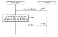
기지국(100)은 제1 TA를 위한 TA 커맨드를 단말 장치(200)에 통지한다(S325). 당해 제1 TA는, 상기 DL 대역에 관한 DL 수신 타이밍을 기준으로 하는 TA이다. 또한, 기지국(100)은 제2 TA를 위한 TA 커맨드를 단말 장치(200)에 통지한다(S327). 당해 제2 TA는, 상기 UL 대역에 관한 DL 수신 타이밍을 기준으로 하는 TA이다.The
단말 장치(200)는 상기 DL 대역에 관한 DL 수신 타이밍과, 상기 제1 TA를 나타내는 정보에 기초하여, 상기 UL 대역에 관한 UL 송신 타이밍을 조정한다(S329). 그리고, 단말 장치(200)는 상기 UL 대역에서의 UL 송신을 행한다(S331). 즉, 단말 장치(200)는 상기 UL 대역에서 UL 신호를 송신한다.The
단말 장치(200)는 상기 UL 대역에 관한 DL 수신 타이밍과, 상기 제2 TA를 나타내는 정보에 기초하여, 상기 UL 대역에 관한 UL 송신 타이밍을 조정한다(S333). 그리고, 단말 장치(200)는 상기 UL 대역에서의 UL 송신을 행한다(S335). 즉, 단말 장치(200)는 상기 UL 대역에서 UL 신호를 송신한다.The
이상, 제1 실시 형태를 설명하였다. 제1 실시 형태에 의하면, 예를 들어, FDD의 UL 대역을 시분할로 DL 및 UL의 양쪽에 사용하는 경우에 당해 UL 대역에서 보다 양호하게 무선 통신을 행하는 것이 가능해진다.The first embodiment has been described above. According to the first embodiment, for example, when the UL band of the FDD is used for both the DL and the UL in a time division manner, the wireless communication can be performed better in the UL band.
보다 구체적으로는, 예를 들어, 단말 장치(200)는 상기 DL 대역에 관한 DL 수신 타이밍, 및 상기 UL 대역에 관한 DL 수신 타이밍 중 어디에 기초하더라도, 상기 UL 대역에 관한 UL 송신 타이밍을 적절하게 조정할 수 있다. 그 때문에, 상기 UL 대역이 시분할로 DL 및 UL의 양쪽에 사용되는 경우에도, 기지국(100)에 있어서의 UL 수신 타이밍의 동기가 실현된다. 그 결과, 상기 UL 대역에서 보다 양호하게 무선 통신이 행하여질 수 있다.More specifically, for example, the
<<5. 제2 실시 형태>><< 5. Second embodiment >>
계속해서, 도 15를 참조하여, 본 개시의 제1 실시 형태를 설명한다.Next, a first embodiment of the present disclosure will be described with reference to Fig.
<5.1. 기술적 과제>5.1. Technical challenges>
제2 실시 형태에 따른 기술적 과제는, 제1 실시 형태에 따른 기술적 과제와 동일하다. 따라서, 여기에서는 중복되는 기재를 생략한다.The technical problem according to the second embodiment is the same as the technical problem according to the first embodiment. Therefore, redundant descriptions are omitted here.
<5.2. 기술적 특징>5.2. Technical Features>
이어서, 제2 실시 형태에 따른 기술적 특징을 설명한다.Next, technical features according to the second embodiment will be described.
(1) 동작 모드의 전환(1) Switching of operation mode
기지국(100)(전환부(151))은 FDD의 UL 대역이 UL에 사용되는 제1 모드와, 상기 UL 대역이 시분할에 의해 DL 및 UL의 양쪽에 사용되는 제2 모드 사이에서, 상기 UL 대역에 관한 동작 모드를 전환한다.The base station 100 (switching unit 151) is configured to switch between a first mode in which the UL band of FDD is used for UL and a second mode in which the UL band is used for both DL and UL by time division, The operation mode is switched.
동작 모드의 전환에 관한 설명은, 제1 실시 형태와 제2 실시 형태 간에 차이는 없다. 따라서, 여기에서는 중복되는 기재를 생략한다.The description of the switching of the operation mode is not different between the first embodiment and the second embodiment. Therefore, redundant descriptions are omitted here.
(2) 타이밍 어드밴스에 관한 지시(2) Instruction on timing advance
제2 실시 형태에서는, 기지국(100)(제어부(153))은 상기 DL 대역에 관한 DL 수신 타이밍을 기준으로 하는 제1 TA에 관한 지시, 및 상기 UL 대역에 관한 DL 수신 타이밍을 기준으로 하는 제2 TA에 관한 지시를 행한다.In the second embodiment, the base station 100 (control unit 153) transmits an instruction regarding the first TA based on the DL reception timing with respect to the DL band, and an instruction with respect to the DL reception timing with respect to the
특히 제2 실시 형태에서는, 상기 제1 TA에 관한 상기 지시는, 상기 제2 모드를 서포트하지 않는 레거시 단말기로의 지시이며, 상기 제2 TA에 관한 상기 지시는, 상기 제2 모드를 서포트하는 단말 장치(200)로의 지시이다.In particular, in the second embodiment, the instruction on the first TA is an instruction to a legacy terminal that does not support the second mode, and the instruction on the second TA is an instruction to the terminal supporting the second mode Instructions to the
한편, 상기 레거시 단말기는, 상기 DL 대역에 관한 DL 수신 타이밍과, 상기 제1 TA를 나타내는 정보에 기초하여, 상기 UL 대역에 관한 UL 송신 타이밍을 조정한다. 특히 제2 실시 형태에서는, 단말 장치(200)(제어부(243))는 상기 동작 모드가 상기 제2 모드인 경우에, 상기 UL 대역에 관한 DL 수신 타이밍과, 상기 제2 TA를 나타내는 정보에 기초하여, 상기 UL 대역에 관한 UL 송신 타이밍을 조정한다. 이에 의해, 예를 들어, 단말 장치(200)는 상기 UL 대역이 시분할로 DL 및 UL의 양쪽에 사용되는 경우에도, 상기 UL 대역에 관한 UL 송신 타이밍을 적절하게 조정할 수 있다.On the other hand, the legacy terminal adjusts the UL transmission timing for the UL band based on the DL reception timing for the DL band and the information indicating the first TA. Particularly, in the second embodiment, the terminal device 200 (the control section 243) determines, based on the DL reception timing relating to the UL band and the information indicating the second TA when the operation mode is the second mode And adjusts the UL transmission timing for the UL band. Thus, for example, the
(a) 제2 모드에서의 지시(a) instructions in the second mode
예를 들어, 기지국(100)(제어부(153))은 상기 동작 모드가 상기 제2 모드인 경우에, 상기 제1 TA에 관한 상기 지시, 및 상기 제2 TA에 관한 상기 지시를 행한다.For example, the base station 100 (control unit 153) performs the above-mentioned instruction about the first TA and the above-mentioned instruction about the second TA when the operation mode is the second mode.
(b) 제1 TA 및 제2 TA(b) The first TA and the second TA
예를 들어, 상기 제2 TA는, 상기 제1 TA보다도 길다.For example, the second TA is longer than the first TA.
상기 제1 TA 및 상기 제2 TA의 예의 설명은, 제1 실시 형태와 제2 실시 형태 간에 차이는 없다. 따라서, 여기에서는 중복되는 기재를 생략한다.The description of the examples of the first TA and the second TA is not different between the first and second embodiments. Therefore, redundant descriptions are omitted here.
(c) 지시의 방법(c) Method of instruction
예를 들어, 기지국(100)(제어부(153))은 타이밍 어드밴스(TA) 커맨드의 통지에 의해, 상기 제1 TA에 관한 상기 지시, 및 상기 제2 TA에 관한 상기 지시를 행한다.For example, the base station 100 (the control unit 153) makes the above instruction about the first TA and the instruction about the second TA by the notification of the timing advance (TA) command.
―개개의 TA 커맨드- Individual TA commands
예를 들어, 상기 TA 커맨드는, 상기 제1 TA를 위한 TA 커맨드와, 상기 제2 TA를 위한 TA 커맨드를 포함한다. 즉, 기지국(100)(제어부(153))은 상기 제1 TA를 위한 TA 커맨드의 통지에 의해, 상기 제1 TA에 관한 지시를 행하고, 상기 제2 TA를 위한 TA 커맨드의 통지에 의해, 상기 제2 TA에 관한 지시를 행한다.For example, the TA command includes a TA command for the first TA and a TA command for the second TA. That is, the base station 100 (the control unit 153) instructs the first TA by the notification of the TA command for the first TA, and upon notification of the TA command for the second TA, And makes an instruction regarding the second TA.
예를 들어, 상기 레거시 단말기는, 상기 제1 TA를 위한 상기 TA 커맨드에 기초하여, 상기 제1 TA를 나타내는 정보를 생성한다. 단말 장치(200)(제어부(243))는 상기 제2 TA를 위한 상기 TA 커맨드에 기초하여, 상기 제2 TA를 나타내는 정보를 생성한다.For example, the legacy terminal generates information indicating the first TA based on the TA command for the first TA. The terminal device 200 (control unit 243) generates information indicating the second TA based on the TA command for the second TA.
(3) 기타(3) Other
(a) UL 대역에 관한 UL/DL 컨피규레이션(a) UL / DL configuration for the UL band
UL/DL 컨피규레이션에 관한 설명은, 제1 실시 형태와 제2 실시 형태 간에 차이는 없다. 따라서, 여기에서는 중복되는 기재를 생략한다.The description of the UL / DL configuration is not different from the first embodiment and the second embodiment. Therefore, redundant descriptions are omitted here.
(b) 랜덤 액세스(b) random access
(b-1) 랜덤 액세스 시간 주파수 영역(b-1) a random access time frequency region
랜덤 액세스 시간 주파수 영역에 관한 설명은, 제1 실시 형태와 제2 실시 형태 간에 차이는 없다. 따라서, 여기에서는 중복되는 기재를 생략한다.The description of the random access time frequency region is not different between the first embodiment and the second embodiment. Therefore, redundant descriptions are omitted here.
(b-2) 랜덤 액세스 수속(b-2) Random access procedure
예를 들어, 단말 장치(200)는 아이들 상태로부터 접속 상태로의 천이를 위해서, 랜덤 액세스 시간 주파수 영역에서 랜덤 액세스 프리앰블을 송신한다.For example, the
예를 들어, 기지국(100)은 랜덤 액세스 응답을 단말 장치(200)로 송신한다. 이때에, 기지국(100)은 TA 커맨드를 단말 장치(200)에 통지한다. 특히, 상기 UL 대역에 관한 상기 동작 모드가 상기 제2 모드인 경우에는, 기지국(100)은 상기 제2 TA를 위한 TA 커맨드를 단말 장치(200)에 통지한다.For example, the
또한, 상기 동작 모드가 상기 제1 모드인 경우에는, 기지국(100)은 제1 TA(상기 DL 대역에 관한 DL 수신 타이밍을 기준으로 하는 TA)를 위한 TA 커맨드를, 단말 장치(200)에 통지한다. 여기에서의 「제1 TA」란, 단순히, 상기 DL 대역에 관한 DL 수신 타이밍을 기준으로 하는 TA를 의미하고, 특정한 단말기(예를 들어, 상기 레거시 단말기)를 위한 TA를 의미하지 않는다. 즉, 단말 장치(200)를 위한 「제1 TA」와, 상기 레거시 단말기를 위한 「제1 TA」는, 서로 다른 TA이다.When the operation mode is the first mode, the
(c) 동기 신호의 송신(c) Transmission of synchronous signal
동기 신호의 송신에 관한 설명은, 제1 실시 형태와 제2 실시 형태 간에 차이는 없다. 따라서, 여기에서는 중복되는 기재를 생략한다.The description of the transmission of the synchronization signal is not different from the first embodiment and the second embodiment. Therefore, redundant descriptions are omitted here.
(d) 스케줄링(d) Scheduling
스케일링에 관한 설명은, 제1 실시 형태와 제2 실시 형태 간에 차이는 없다. 따라서, 여기에서는 중복되는 기재를 생략한다.The description of the scaling is not different between the first embodiment and the second embodiment. Therefore, redundant descriptions are omitted here.
(e) 캐퍼빌리티 정보의 통지(e) Notification of the capability information
캐퍼빌리티 정보의 통지에 관한 설명은, 제1 실시 형태와 제2 실시 형태 간에 차이는 없다. 따라서, 여기에서는 중복되는 기재를 생략한다.The description of the notification of the capability information does not differ between the first embodiment and the second embodiment. Therefore, redundant descriptions are omitted here.
<5.3. 처리의 흐름>5.3. Processing flow>
이어서, 도 15를 참조하여, 제2 실시 형태에 따른 처리의 예를 설명한다.Next, an example of the process according to the second embodiment will be described with reference to Fig.
(1) 제1 모드에서의 처리(1) Processing in the first mode
제1 모드에서의 처리에 관한 설명은, 제1 실시 형태와 제2 실시 형태 간에 차이는 없다. 따라서, 여기에서는 중복되는 기재를 생략한다.The description of the processing in the first mode is not different from the first embodiment and the second embodiment. Therefore, redundant descriptions are omitted here.
(2) 제2 모드에서의 처리(2) Processing in the second mode
도 15는, 제2 실시 형태에 따른 제2 모드에서의 처리의 개략적인 흐름의 일례를 도시하는 시퀀스도이다.15 is a sequence diagram showing an example of a schematic flow of processing in the second mode according to the second embodiment.
기지국(100)은 모드 전환 정보를 단말 장치(200)에 통지한다(S341). 당해 모드 전환 정보는, 제1 모드와 제2 모드 사이에서의 상기 UL 대역에 관한 동작 모드의 전환을 나타내는 정보이다. 특히, 상기 모드 전환 정보는, 상기 제1 모드로부터 상기 제2 모드로의 상기 동작 모드의 전환을 나타낸다. 상기 제1 모드는, 상기 UL 대역이 UL에 사용되는 모드이며, 상기 제2 모드는, 상기 UL 대역이 시분할에 의해 DL 및 UL의 양쪽에 사용되는 모드이다.The
기지국(100)은 상기 동작 모드를 상기 제1 모드로부터 상기 제2 모드로 전환한다(S343).The
기지국(100)은 제1 TA를 위한 TA 커맨드를 레거시 단말기에 통지한다(S345). 당해 제1 TA는, 상기 DL 대역에 관한 DL 수신 타이밍을 기준으로 하는 TA이다. 또한, 기지국(100)은 제2 TA를 위한 TA 커맨드를 단말 장치(200)에 통지한다(S347). 당해 제2 TA는, 상기 UL 대역에 관한 DL 수신 타이밍을 기준으로 하는 TA이다.The
단말 장치(200)는 상기 UL 대역에 관한 DL 수신 타이밍과, 상기 제2 TA를 나타내는 정보에 기초하여, 상기 UL 대역에 관한 UL 송신 타이밍을 조정한다(S349). 그리고, 단말 장치(200)는 상기 UL 대역에서의 UL 송신을 행한다(S351). 즉, 단말 장치(200)는 상기 UL 대역에서 UL 신호를 송신한다.The
상기 레거시 단말기는, 상기 DL 대역에 관한 DL 수신 타이밍과, 상기 제1 TA를 나타내는 정보에 기초하여, 상기 UL 대역에 관한 UL 송신 타이밍을 조정한다(S353). 그리고, 상기 레거시 단말기는, 상기 UL 대역에서의 UL 송신을 행한다(S355). 즉, 단말 장치(200)는 상기 UL 대역에서 UL 신호를 송신한다.The legacy terminal adjusts the UL transmission timing for the UL band based on the DL reception timing relating to the DL band and the information indicating the first TA (S353). Then, the legacy terminal performs UL transmission in the UL band (S355). That is, the
이상, 제2 실시 형태를 설명하였다. 제2 실시 형태에 의하면, 예를 들어, FDD의 UL 대역을 시분할로 DL 및 UL의 양쪽에 사용하는 경우에 당해 UL 대역에서 보다 양호하게 무선 통신을 행하는 것이 가능해진다.The second embodiment has been described above. According to the second embodiment, for example, when the UL band of the FDD is used for both the DL and the UL in a time division manner, the wireless communication can be performed better in the UL band.
보다 구체적으로는, 예를 들어, 단말 장치(200)는 상기 동작 모드가 상기 제2 모드인 경우에는, 상기 DL 대역에 관한 DL 수신 타이밍에 기초하지 않고, 상기 UL 대역에 관한 DL 수신 타이밍에 기초하여, 상기 UL 대역에 관한 UL 송신 타이밍을 조정한다. 그 때문에, 상기 UL 대역이 시분할로 DL 및 UL의 양쪽에 사용되는 경우에도, 기지국(100)에 있어서의 UL 수신 타이밍의 동기가 실현된다. 그 결과, 상기 UL 대역에서 보다 양호하게 무선 통신이 행하여질 수 있다. 또한, 단말 장치(200)를 위한 TA의 수가 증가하지 않으므로, 시그널링의 오버헤드의 증가가 억제될 수 있다.More specifically, for example, in the case where the operation mode is the second mode, the
<<6. 제3 실시 형태>><< 6. Third embodiment >>
계속해서, 도 16 및 도 17을 참조하여, 본 개시의 제3 실시 형태를 설명한다.Next, a third embodiment of the present disclosure will be described with reference to Figs. 16 and 17. Fig.
<6.1. 기술적 과제><6.1. Technical challenges>
제3 실시 형태에 따른 기술적 과제는, 제1 실시 형태에 따른 기술적 과제와 동일하다. 따라서, 여기에서는 중복되는 기재를 생략한다.The technical problem according to the third embodiment is the same as the technical problem according to the first embodiment. Therefore, redundant descriptions are omitted here.
<5.2. 기술적 특징>5.2. Technical Features>
이어서, 도 16을 참조하여, 제3 실시 형태에 따른 기술적 특징을 설명한다.Next, the technical features according to the third embodiment will be described with reference to Fig.
(1) 동작 모드의 전환(1) Switching of operation mode
기지국(100)(전환부(151))은 FDD의 UL 대역이 UL에 사용되는 제1 모드와, 상기 UL 대역이 시분할에 의해 DL 및 UL의 양쪽에 사용되는 제2 모드 사이에서, 상기 UL 대역에 관한 동작 모드를 전환한다.The base station 100 (switching unit 151) is configured to switch between a first mode in which the UL band of FDD is used for UL and a second mode in which the UL band is used for both DL and UL by time division, The operation mode is switched.
(a) 전환의 트리거(a) triggers the transition
상기 동작 모드의 전환의 트리거에 관한 설명은, 제1 실시 형태와 제3 실시 형태 간에 차이는 없다. 따라서, 여기에서는 중복되는 기재를 생략한다.The description of the trigger of the switching of the operation mode is not different from the first embodiment and the third embodiment. Therefore, redundant descriptions are omitted here.
(b) 전환의 통지(b) Notification of Conversion
상기 동작 모드의 전환의 통지에 대한 설명은, 제1 실시 형태와 제3 실시 형태 간에 차이는 없다. 따라서, 여기에서는 중복되는 기재를 생략한다.The description of the notification of the switching of the operation mode is not different between the first embodiment and the third embodiment. Therefore, redundant descriptions are omitted here.
(c) 전환에 따른 단말 장치(200)의 동작(c) Operation of the
상기 동작 모드의 전환에 따른 단말 장치(200)의 동작에 대한 설명은, 제1 실시 형태와 제3 실시 형태 간에 차이는 없다. 따라서, 여기에서는 중복되는 기재를 생략한다.The description of the operation of the
(2) 다운링크 송신의 타이밍(2) Timing of downlink transmission
제3 실시 형태에서는, 기지국(100)(제어부(153))은 상기 동작 모드가 상기 제2 모드인 경우에, 상기 UL 대역에 대응하는 FDD의 DL 대역에 관한 DL 송신 타이밍과, 상기 UL 대역에 관한 DL 송신 타이밍을 동기시킨다. 이하, 이 점에 대해서, 도 16을 참조하여 구체예를 설명한다.In the third embodiment, when the operation mode is the second mode, the base station 100 (the control unit 153) transmits the DL transmission timing relating to the DL band of the FDD corresponding to the UL band, To synchronize the DL transmission timing. Hereinafter, a specific example will be described with reference to Fig. 16 with respect to this point.
도 16은, DL 대역 및 UL 대역에 관한 DL 송신 타이밍의 예를 설명하기 위한 설명도이다. 도 16을 참조하면, UL 대역에 관한 동작 모드가 제2 모드인 경우에 있어서의 기지국(100) 및 단말 장치(200)의 송수신 타이밍이 도시되어 있다. 기지국(100)에서는, UL 대역에서의 UL로부터 DL로의 전환에 시간(51)을 요한다. 그러나, 제2 실시 형태에서는, 기지국(100)은 시간(51)을 고려하여, 상기 UL 대역에 관한 DL 송신 타이밍을, DL 대역에 관한 DL 송신 타이밍과 동기시킨다. 그 결과, 단말 장치(200)에서는, 예를 들어, 상기 DL 대역에 관한 DL 수신 타이밍과, 상기 UL 대역에 관한 DL 수신 타이밍이 동기한다. 그 때문에, 단말 장치(200)는 DL 수신 타이밍(상기 DL 대역에 관한 DL 수신 타이밍, 또는 상기 UL 대역에 관한 DL 수신 타이밍)과 TA(53)에 기초하여, UL 대역에 관한 UL 송신 타이밍을 조정한다.16 is an explanatory view for explaining an example of a DL transmission timing with respect to the DL band and the UL band; Referring to Fig. 16, transmission / reception timings of the
이에 의해, 예를 들어, 단말 장치(200)는 상기 UL 대역이 시분할로 DL 및 UL의 양쪽에 사용되는 경우에도, 상기 UL 대역에 관한 UL 송신 타이밍을 적절하게 조정할 수 있다.Thus, for example, the
또한, 본 명세서에 있어서, 「타이밍을 동기시키는」이란, 「타이밍 간의 차가 완전히 없어지도록, 당해 타이밍을 동기시키는」 것을 의미하지 않아도 되고, 예를 들어, 「타이밍 간의 차가 소정 범위 내에 수렴되도록, 당해 타이밍을 동기시키는」 것을 의미해도 된다.In this specification, " synchronizing the timing " does not necessarily mean " synchronizing the timings so that the difference between the timings disappears completely ", and for example, Synchronize the timing ".
(3) 업링크 수신의 타이밍(3) Timing of uplink reception
(a) 제2 모드(a) the second mode
예를 들어, 적어도 상기 동작 모드가 상기 제2 모드인 경우에, 상기 UL 대역에 관한 UL 수신 타이밍은, 상기 DL 대역에 관한 DL 송신 타이밍보다도 소정 시간만큼 빠르다. 예를 들어, 당해 소정 시간은, 상기 UL 대역에서의 UL로부터 DL로의 전환에 요하는 시간이다.For example, when at least the operation mode is the second mode, the UL reception timing with respect to the UL band is earlier than the DL transmission timing with respect to the DL band by a predetermined time. For example, the predetermined time is a time required for switching from UL to DL in the UL band.
도 16을 다시 참조하면, 기지국(100)에 있어서, UL 대역에 관한 UL 수신 타이밍은, DL 대역에 관한 DL 송신 타이밍보다도 시간(51)(즉, 상기 UL 대역에서의 UL로부터 DL로의 전환에 요하는 시간)만큼 빠르다.Referring back to FIG. 16, in the
이에 의해, 예를 들어, 단말 장치(200)는 상기 UL 대역이 시분할로 DL 및 UL의 양쪽에 사용되는 경우에도, 상기 DL 대역에 관한 DL 송신 타이밍과, 상기 UL 대역에 관한 DL 송신 타이밍을 동기시키는 것이 가능해진다.Thus, for example, even when the UL band is used for both DL and UL in time division, the
(b) 제1 모드(b) the first mode
(b-1) 제1 예(b-1) Example 1
제1 예로서, 상기 동작 모드가 상기 제1 모드인 경우에, 기지국(100)에 있어서, 상기 UL 대역에 관한 UL 수신 타이밍은, 상기 DL 대역에 관한 DL 송신 타이밍과 동기한다. 즉, 기지국(100)은 상기 동작 모드가 상기 제1 모드로부터 상기 제2 모드로 전환되는 때에, 상기 UL 대역에 관한 UL 수신 타이밍을 상기 소정 시간만큼 빠르게 한다.As a first example, when the operation mode is the first mode, the UL reception timing regarding the UL band in the
(b-2) 제2 예(b-2) Example 2
제2 예로서, 상기 동작 모드가 상기 제1 모드인 경우에도, 기지국(100)에 있어서, 상기 UL 대역에 관한 UL 수신 타이밍은, 상기 DL 대역에 관한 DL 송신 타이밍보다도 상기 소정 시간만큼 빨라도 된다. 즉, 기지국(100)은 상기 동작 모드의 전환이 있었다고 해도, 상기 UL 대역에 관한 UL 수신 타이밍을 변경하지 않아도 된다.As a second example, even when the operation mode is the first mode, the UL reception timing of the UL band in the
(4) 타이밍 어드밴스에 관한 지시(4) Instructions regarding timing advance
(a) 제1 예(a) Example 1
상술한 바와 같이, 제1 예로서, 상기 동작 모드가 상기 제1 모드인 경우에, 상기 UL 대역에 관한 UL 수신 타이밍은, 상기 DL 대역에 관한 DL 송신 타이밍과 동기한다. 또한, 상기 동작 모드가 상기 제2 모드인 경우에, 상기 UL 대역에 관한 UL 수신 타이밍은, 상기 DL 대역에 관한 DL 송신 타이밍보다도 상기 소정 시간만큼 빠르다.As described above, as a first example, when the operation mode is the first mode, the UL reception timing regarding the UL band is synchronized with the DL transmission timing regarding the DL band. Further, when the operation mode is the second mode, the UL reception timing regarding the UL band is earlier than the DL transmission timing regarding the DL band by the predetermined time.
예를 들어, 기지국(100)(제어부(153))은 상기 제1 모드로부터 상기 제2 모드로의 상기 동작 모드의 전환에 따라서 상기 UL 대역에서의 UL 송신의 TA가 상기 소정 시간만큼 길어지도록, 당해 TA에 관한 지시를 행한다. 당해 지시는, 단말 장치(200)로의 지시이다. 이에 의해, 예를 들어, 상기 전환에 따라서 상기 UL 대역에 관한 UL 수신 타이밍을 소정 시간만큼 빠르게 하는 것이 가능해진다. 그 결과, 예를 들어, UL 서브프레임과 DL 서브프레임 사이에서의 충돌이 방지된다.For example, the base station 100 (the control unit 153) may change the operation mode from the first mode to the second mode so that the TA of the UL transmission in the UL band becomes longer by the predetermined time, And makes an instruction about the TA. This instruction is an instruction to the
(a-1) TA 커맨드의 통지(a-1) Notification of TA command
예를 들어, 기지국(100)(제어부(153))은 상기 전환의 6서브프레임 전의 서브프레임에 있어서의 TA 커맨드의 통지에 의해, 상기 TA에 관한 상기 지시를 행한다. 예를 들어, 당해 TA 커맨드는, 상기 UL 대역에서의 UL 송신의 상기 TA를 상기 소정 시간만큼 길게 하는 값(TA)을 나타낸다. 이에 의해, 예를 들어, 상기 전환의 타이밍에서, 상기 TA를 상기 소정 시간만큼 길게 하는 것이 가능해진다.For example, the base station 100 (the control unit 153) makes the above-mentioned instruction about the TA by notifying the TA command in the sub-frame six subframes before the switching. For example, the art TA command, indicates a value (TA) to the TA of the UL transmission in the UL band as long as the predetermined time. Thus, for example, at the timing of switching, the TA can be made longer by the predetermined time.
예를 들어, 단말 장치(200)(제어부(243))는 상기 TA 커맨드에 기초하여, 상기 UL 대역에서의 UL 송신의 TA를 나타내는 정보(예를 들어, NTA)를 생성한다.For example, the terminal device 200 (control unit 243) generates information (e.g., NTA ) indicating the TA of UL transmission in the UL band based on the TA command.
또한, 예를 들어, 기지국(100)(제어부(153))은 상기 제2 모드로부터 상기 제1 모드로의 상기 동작 모드의 전환 전에는, 상기 UL 대역에서의 UL 송신의 TA가 상기 소정 시간만큼 짧아지도록, 당해 TA에 관한 지시를 행한다. 예를 들어, 기지국(100)(제어부(153))은 상기 전환의 6서브프레임 전의 서브프레임에 있어서의 TA 커맨드의 통지에 의해, 상기 TA에 관한 상기 지시를 행한다.For example, the base station 100 (the control unit 153) may determine that the TA of the UL transmission in the UL band is shortened by the predetermined time before the switching of the operation mode from the second mode to the first mode An instruction regarding the TA is made. For example, the base station 100 (the control unit 153) makes the above-mentioned instruction about the TA by notifying the TA command in the sub-frame six subframes before the switching.
(a-2) 오프셋의 통지(a-2) Notification of Offset
기지국(100)(제어부(153))은 상기 소정 시간에 대응하는 오프셋을 나타내는 정보(이하, 「오프셋 정보」라 칭한다)의 통지에 의해, 상기 TA에 관한 상기 지시를 행해도 된다.The base station 100 (the control unit 153) may perform the above instruction on the TA by notifying the information indicating the offset corresponding to the predetermined time (hereinafter, referred to as " offset information ").
단말 장치(200)(제어부(243))는 상기 오프셋 정보에 기초하여, 상기 UL 대역에서의 UL 송신의 TA를 나타내는 정보(예를 들어, NTA)를 생성해도 된다.The terminal device 200 (control section 243) may generate information (e.g., NTA ) indicating the TA of the UL transmission in the UL band based on the offset information.
―구체적인 예- Specific examples
구체적으로는, 기지국(100)(제어부(153))은 (예를 들어, 시스템 정보 중에서, 또는 시그널링에 의해,) 오프셋 정보 NTA_offset를 단말 장치(200)에 통지해도 된다. 단말 장치(200)는 NTA와 NTA_offset으로부터, 새로운 NTA를 산출해도 된다. 즉, 단말 장치(200)는 상기 TA를 나타내는 정보인 NTA를 새롭게 생성해도 된다. 또한, NTA_offset는, 소정값(예를 들어, 624)이어도 된다.Specifically, the base station 100 (control section 153) (e.g., from the system information, or by signaling) may notify offset informationTA N_offset to the
―오프셋의 사용 방법(동작 모드의 전환 시의 사용)- How to use offset (Use when switching operation mode)
단말 장치(200)는 상기 UL 대역의 상기 동작 모드가 상기 제1 모드로부터 상기 제2 모드로 전환되는 때에, 상기 오프셋 정보에 기초하여, 상기 TA를 나타내는 상기 정보(예를 들어, NTA)를 생성해도 된다. 그 후, 단말 장치(200)는 TA 커맨드에 기초하여, 상기 TA를 나타내는 상기 정보(예를 들어, NTA)를 생성(갱신)해도 된다.When the operation mode of the UL band is switched from the first mode to the second mode, the
―통지의 예- Examples of notifications
기지국(100)(제어부(153))은 시스템 정보 중에서, 상기 오프셋 정보의 통지를 행해도 된다. 또는, 기지국(100)(제어부(153))은 개별의 시그널링에 의해, 상기 오프셋 정보의 통지를 행해도 된다. 당해 개별의 시그널링은, RRC 시그널링이어도 된다.The base station 100 (the control unit 153) may notify of the offset information among the system information. Alternatively, the base station 100 (the control unit 153) may notify the offset information by individual signaling. The individual signaling may be RRC signaling.
―기타-Other
기지국(100)이 상기 오프셋 정보(예를 들어, NTA_offset)를 단말 장치(200)에 통지하는 대신, 상기 오프셋 정보가 단말 장치(200)에 있어서 미리 기억되어 있어도 된다.The offset information may be previously stored in the
(b) 제2 예(b) Example 2
상술한 바와 같이, 제2 예로서, 상기 UL 대역에 관한 UL 수신 타이밍은, 상기 동작 모드가 상기 제1 모드인지 상기 제2 모드인지에 상관없이, 상기 DL 대역에 관한 DL 송신 타이밍보다도 상기 소정 시간만큼 빨라도 된다.As described above, as a second example, the UL reception timing regarding the UL band is set such that the DL reception timing with respect to the UL band is shorter than the DL transmission timing with respect to the DL band, regardless of whether the operation mode is the first mode or the second mode. .
이 경우에, 기지국(100)(제어부(153))은 상기 동작 모드의 상기 전환의 유무에 상관없이, 통상대로, 상기 UL 대역에서의 UL 송신의 TA에 관한 지시를 행해도 된다. 예를 들어, 기지국(100)(제어부(153))은 통상대로, TA 커맨드의 통지에 의해, 상기 TA에 관한 지시를 행해도 된다.In this case, the base station 100 (control unit 153) may instruct the TA of the UL transmission in the UL band, as usual, regardless of whether or not the switching of the operation mode is performed. For example, the base station 100 (the control unit 153) may instruct the TA by the notification of the TA command as usual.
(c) 단말 장치(200)의 동작(c) Operation of the
예를 들어, 단말 장치(200)(제어부(243))는 DL 수신 타이밍과, 상기 UL 대역에서의 UL 송신의 TA에 기초하여, 상기 UL 대역에 관한 UL 송신 타이밍을 조정한다. 상기 동작 모드가 상기 제1 모드인 경우에는, 상기 DL 수신 타이밍은, 상기 DL 대역에 관한 DL 수신 타이밍이다. 상기 동작 모드가 상기 제2 모드인 경우에는, 상기 DL 수신 타이밍은, 상기 DL 대역에 관한 DL 수신 타이밍이어도 되고, 또는, 상기 UL 대역에 관한 DL 수신 타이밍이어도 된다.For example, the terminal device 200 (control section 243) adjusts the UL transmission timing for the UL band based on the DL reception timing and the TA of the UL transmission in the UL band. When the operation mode is the first mode, the DL reception timing is a DL reception timing with respect to the DL band. When the operation mode is the second mode, the DL reception timing may be the DL reception timing with respect to the DL band or the DL reception timing with respect to the UL band.
(5) 기타(5) Others
(a) 업링크 대역에 관한 UL/DL 컨피규레이션의 통지(a) Notification of UL / DL configuration for the uplink band
UL/DL 컨피규레이션에 관한 설명은, 제1 실시 형태와 제3 실시 형태 간에 차이는 없다. 따라서, 여기에서는 중복되는 기재를 생략한다.The description of the UL / DL configuration is not different between the first embodiment and the third embodiment. Therefore, redundant descriptions are omitted here.
(b) 랜덤 액세스(b) random access
(b-1) 랜덤 액세스 시간 주파수 영역(b-1) a random access time frequency region
랜덤 액세스 시간 주파수 영역에 관한 설명은, 제1 실시 형태와 제3 실시 형태 간에 차이는 없다. 따라서, 여기에서는 중복되는 기재를 생략한다.The description of the random access time frequency domain is not different from that of the first embodiment and the third embodiment. Therefore, redundant descriptions are omitted here.
(b-2) 랜덤 액세스 수속(b-2) Random access procedure
예를 들어, 단말 장치(200)는 아이들 상태로부터 접속 상태로의 천이를 위해서, 랜덤 액세스 시간 주파수 영역에서 랜덤 액세스 프리앰블을 송신한다.For example, the
예를 들어, 기지국(100)은 랜덤 액세스 응답을 단말 장치(200)로 송신한다. 이때에, 기지국(100)은 TA 커맨드를 단말 장치(200)에 통지한다.For example, the
(c) 동기 신호(c) Sync signal
예를 들어, 상기 동작 모드가 상기 제2 모드여도, 상기 UL 대역에서 동기 신호는 송신되지 않는다. 즉, 기지국(100)은 상기 동작 모드가 상기 제2 모드여도, 상기 UL 대역에서 동기 신호를 송신하지 않는다. 상기 UL 대역에 관한 DL 송신 타이밍은, 상기 DL 대역에 관한 DL 송신 타이밍과 동기하고 있기 때문이다. 이에 의해, 예를 들어, 무선 리소스가 절약된다.For example, even if the operation mode is the second mode, the synchronization signal is not transmitted in the UL band. That is, the
또는, 기지국(100)은 상기 동작 모드가 상기 제2 모드인 경우에, 상기 UL 대역에서 동기 신호를 송신해도 된다.Alternatively, the
(d) 스케줄링(d) Scheduling
스케일링에 관한 설명은, 제1 실시 형태와 제3 실시 형태 간에 차이는 없다. 따라서, 여기에서는 중복되는 기재를 생략한다.The description of the scaling is not different between the first and third embodiments. Therefore, redundant descriptions are omitted here.
(e) 캐퍼빌리티 정보의 통지(e) Notification of the capability information
캐퍼빌리티 정보의 통지에 관한 설명은, 제1 실시 형태와 제3 실시 형태 간에 차이는 없다. 따라서, 여기에서는 중복되는 기재를 생략한다.The description of the notification of the capability information does not differ between the first embodiment and the third embodiment. Therefore, redundant descriptions are omitted here.
<6.3. 처리의 흐름><6.3. Processing flow>
이어서, 도 17을 참조하여, 제3 실시 형태에 따른 처리의 예를 설명한다. 도 17은, 제3 실시 형태에 따른 처리의 개략적인 흐름의 일례를 도시하는 시퀀스도이다. 또한, 당해 처리의 설명에 있어서, FDD의 UL 대역에 관한 동작 모드는, 처음에, 제1 모드로 되어 있는 것으로 한다.Next, an example of the process according to the third embodiment will be described with reference to Fig. 17 is a sequence diagram showing an example of a schematic flow of processing according to the third embodiment. In the description of the processing, it is assumed that the operation mode of the FDD in the UL band is initially in the first mode.
기지국(100)은 TA를 위한 TA 커맨드를 단말 장치(200)에 통지한다(S361).The
단말 장치(200)는 FDD의 DL 대역에 관한 DL 수신 타이밍과, 상기 TA를 나타내는 정보에 기초하여, FDD의 UL 대역에 관한 UL 송신 타이밍을 조정한다(S363). 그리고, 단말 장치(200)는 상기 UL 대역에서의 UL 송신을 행한다(S365). 즉, 단말 장치(200)는 상기 UL 대역에서 UL 신호를 송신한다.The
기지국(100)은 모드 전환 정보를 단말 장치(200)에 통지한다(S367). 당해 모드 전환 정보는, 제1 모드와 제2 모드 사이에서의 상기 UL 대역에 관한 동작 모드의 전환을 나타내는 정보이다. 특히, 상기 모드 전환 정보는, 상기 제1 모드로부터 상기 제2 모드로의 상기 동작 모드의 전환을 나타낸다. 상기 제1 모드는, 상기 UL 대역이 UL에 사용되는 모드이며, 상기 제2 모드는, 상기 UL 대역이 시분할에 의해 DL 및 UL의 양쪽에 사용되는 모드이다.The
기지국(100)은 상기 동작 모드의 상기 전환 전에, TA를 위한 TA 커맨드를 단말 장치(200)에 통지한다(S369). 예를 들어, 기지국(100)은 상기 전환의 6서브프레임 전의 서브프레임에 있어서, 상기 TA 커맨드를 단말 장치(200)에 통지한다.The
기지국(100)은 상기 동작 모드를 상기 제1 모드로부터 상기 제2 모드로 전환한다(S371). 또한, 기지국(100)은 상기 DL 대역에 관한 DL 송신 타이밍과, 상기 UL 대역에 관한 DL 송신 타이밍을 동기시킨다(S373).The
단말 장치(200)는 상기 DL 대역 또는 상기 UL 대역에 관한 DL 수신 타이밍과, 상기 TA를 나타내는 정보에 기초하여, 상기 UL 대역에 관한 UL 송신 타이밍을 조정한다(S375). 그리고, 단말 장치(200)는 상기 UL 대역에서의 UL 송신을 행한다(S377). 즉, 단말 장치(200)는 상기 UL 대역에서 UL 신호를 송신한다.The
이상, 제3 실시 형태를 설명하였다. 제3 실시 형태에 의하면, 예를 들어, FDD의 UL 대역을 시분할로 DL 및 UL의 양쪽에 사용하는 경우에 당해 UL 대역에서 보다 양호하게 무선 통신을 행하는 것이 가능해진다.The third embodiment has been described above. According to the third embodiment, for example, when the UL band of the FDD is used for both the DL and the UL in a time division manner, the wireless communication can be performed better in the UL band.
보다 구체적으로는, 예를 들어, 단말 장치(200)는 상기 DL 대역에 관한 DL 수신 타이밍, 및 상기 UL 대역에 관한 DL 수신 타이밍 중 어디에 기초하더라도, 상기 UL 대역에 관한 UL 송신 타이밍을 적절하게 조정할 수 있다. 그 때문에, 상기 UL 대역이 시분할로 DL 및 UL의 양쪽에 사용되는 경우에도, 기지국(100)에 있어서의 UL 수신 타이밍의 동기가 실현된다. 그 결과, 상기 UL 대역에서 보다 양호하게 무선 통신이 행하여질 수 있다. 또한, 단말 장치(200)를 위한 TA의 수가 증가하지 않으므로, 시그널링의 오버헤드의 증가가 억제될 수 있다.More specifically, for example, the
<<7. 제4 실시 형태>><< 7. Fourth embodiment >>
계속해서, 도 18을 참조하여, 본 개시의 제4 실시 형태를 설명한다.Next, a fourth embodiment of the present disclosure will be described with reference to Fig.
<7.1. 기술적 과제><7.1. Technical challenges>
제4 실시 형태에 따른 기술적 과제는, 제1 실시 형태에 따른 기술적 과제와 동일하다. 따라서, 여기에서는 중복되는 기재를 생략한다.The technical problem according to the fourth embodiment is the same as the technical problem according to the first embodiment. Therefore, redundant descriptions are omitted here.
<7.2. 기술적 특징><7.2. Technical Features>
이어서, 제4 실시 형태에 따른 기술적 특징을 설명한다.Next, technical features according to the fourth embodiment will be described.
(1) 동작 모드의 전환(1) Switching of operation mode
기지국(100)(전환부(151))은 FDD의 UL 대역이 UL에 사용되는 제1 모드와, 상기 UL 대역이 시분할에 의해 DL 및 UL의 양쪽에 사용되는 제2 모드 사이에서, 상기 UL 대역에 관한 동작 모드를 전환한다.The base station 100 (switching unit 151) is configured to switch between a first mode in which the UL band of FDD is used for UL and a second mode in which the UL band is used for both DL and UL by time division, The operation mode is switched.
동작 모드의 전환에 관한 설명은, 제1 실시 형태와 제4 실시 형태 간에 차이는 없다. 따라서, 여기에서는 중복되는 기재를 생략한다.The description of the switching of the operation mode is not different between the first embodiment and the fourth embodiment. Therefore, redundant descriptions are omitted here.
(2) 타이밍 어드밴스에 관한 지시(2) Instruction on timing advance
제4 실시 형태에서는, 기지국(100)(제어부(153))은 상기 동작 모드가 상기 제1 모드인지 또는 상기 제2 모드인지에 상관없이, 상기 UL 대역에 대응하는 FDD의 DL 대역에 관한 DL 수신 타이밍을 기준으로 하는 TA에 관한 지시를 행한다. 당해 지시는, 단말 장치(200)로의 지시이다. 또한, 기지국(100)(제어부(153))은 상기 UL 대역에 관한 DL 수신 타이밍을 기준으로 하는 TA에 관한 지시를 행하지 않는다.In the fourth embodiment, the base station 100 (the control unit 153) determines whether or not the DL mode regarding the DL band of the FDD corresponding to the UL band, regardless of whether the operation mode is the first mode or the second mode And makes an instruction regarding the TA based on the timing. This instruction is an instruction to the
한편, 특히 제4 실시 형태에서는, 단말 장치(200)(제어부(243))는 상기 동작 모드가 상기 제1 모드인지 또는 상기 제2 모드인지에 상관없이, 상기 DL 대역에 관한 DL 수신 타이밍에 기초하여, 상기 UL 대역에 관한 UL 송신 타이밍을 조정한다.On the other hand, in the fourth embodiment in particular, the terminal apparatus 200 (the control section 243) determines whether the operation mode is the first mode or the second mode, based on the DL reception timing with respect to the DL band And adjusts the UL transmission timing for the UL band.
구체적으로는, 예를 들어, 기지국(100)(제어부(153))은 상기 DL 대역에 관한 DL 수신 타이밍을 기준으로 하는 상기 TA를 위한 TA 커맨드의 통지에 의해, 당해 TA에 관한 상기 지시를 행한다. 단말 장치(정보 취득부(241))는 상기 TA 커맨드를 취득한다. 그리고, 단말 장치(200)(제어부(243))는 상기 DL 대역에 관한 DL 수신 타이밍과, 상기 TA를 나타내는 정보에 기초하여, 상기 UL 대역에 관한 UL 송신 타이밍을 조정한다. 또한, 단말 장치(200)(제어부(243))는 상기 TA 커맨드에 기초하여, 상기 TA를 나타내는 상기 정보를 생성한다.More specifically, for example, the base station 100 (the control unit 153) performs the above-mentioned instruction about the TA by notifying the TA command for the TA based on the DL reception timing regarding the DL band . The terminal device (information acquisition section 241) acquires the TA command. Then, the terminal device 200 (the control section 243) adjusts the UL transmission timing for the UL band based on the DL reception timing regarding the DL band and the information indicating the TA. Further, the terminal device 200 (the control section 243) generates the information indicating the TA based on the TA command.
도 11을 다시 참조하면, 예를 들어, 기지국(100)은 상기 UL 대역에 관한 동작 모드에 상관없이, TA(43)(DL 대역에 관한 DL 수신 타이밍을 기준으로 하는 TA)를 위한 TA 커맨드를 단말 장치(200)에 통지한다. 단말 장치(200)(제어부(243))는 상기 UL 대역에 관한 동작 모드에 상관없이, 상기 DL 대역에 관한 DL 수신 타이밍과, TA(43)를 나타내는 정보에 기초하여, 상기 UL 대역에서의 UL 송신 타이밍을 조정한다.11, for example, the
(3) 기타(3) Other
(a) 업링크 대역에 관한 UL/DL 컨피규레이션의 통지(a) Notification of UL / DL configuration for the uplink band
UL/DL 컨피규레이션에 관한 설명은, 제1 실시 형태와 제4 실시 형태 간에 차이는 없다. 따라서, 여기에서는 중복되는 기재를 생략한다.The description of the UL / DL configuration does not differ between the first and fourth embodiments. Therefore, redundant descriptions are omitted here.
(b) 랜덤 액세스(b) random access
(b-1) 랜덤 액세스 시간 주파수 영역(b-1) a random access time frequency region
랜덤 액세스 시간 주파수 영역에 관한 설명은, 제1 실시 형태와 제4 실시 형태 간에 차이는 없다. 따라서, 여기에서는 중복되는 기재를 생략한다.The description of the random access time frequency region is not different between the first embodiment and the fourth embodiment. Therefore, redundant descriptions are omitted here.
(b-2) 랜덤 액세스 수속(b-2) Random access procedure
예를 들어, 단말 장치(200)는 아이들 상태로부터 접속 상태로의 천이를 위해서, 랜덤 액세스 시간 주파수 영역에서 랜덤 액세스 프리앰블을 송신한다.For example, the
예를 들어, 기지국(100)은 랜덤 액세스 응답을 단말 장치(200)로 송신한다. 이때에, 기지국(100)은 TA 커맨드를 단말 장치(200)에 통지한다.For example, the
(c) 동기 신호(c) Sync signal
동기 신호의 송신에 관한 설명은, 제1 실시 형태와 제4 실시 형태 간에 차이는 없다. 따라서, 여기에서는 중복되는 기재를 생략한다.The description of the transmission of the synchronization signal is not different between the first and fourth embodiments. Therefore, redundant descriptions are omitted here.
(d) 스케줄링(d) Scheduling
스케일링에 관한 설명은, 제1 실시 형태와 제4 실시 형태 간에 차이는 없다. 따라서, 여기에서는 중복되는 기재를 생략한다.The description of the scaling is not different between the first embodiment and the fourth embodiment. Therefore, redundant descriptions are omitted here.
(e) 캐퍼빌리티 정보의 통지(e) Notification of the capability information
캐퍼빌리티 정보의 통지에 관한 설명은, 제1 실시 형태와 제4 실시 형태 간에 차이는 없다. 따라서, 여기에서는 중복되는 기재를 생략한다.The description of the notification of the capability information does not differ between the first and fourth embodiments. Therefore, redundant descriptions are omitted here.
<7.3. 처리의 흐름><7.3. Processing flow>
이어서, 도 18을 참조하여, 제4 실시 형태에 따른 처리의 예를 설명한다. 도 18은, 제4 실시 형태에 따른 처리의 개략적인 흐름의 일례를 도시하는 시퀀스도이다. 또한, 당해 처리의 설명에 있어서, FDD의 UL 대역에 관한 동작 모드는, 처음에, 제1 모드로 되어 있는 것으로 한다.Next, an example of processing according to the fourth embodiment will be described with reference to Fig. 18 is a sequence diagram showing an example of a schematic flow of processing according to the fourth embodiment. In the description of the processing, it is assumed that the operation mode of the FDD in the UL band is initially in the first mode.
기지국(100)은 FDD의 DL 대역에 관한 DL 수신 타이밍을 기준으로 하는 TA를 위한 TA 커맨드를 단말 장치(200)에 통지한다(S381).The
단말 장치(200)는 상기 DL 대역에 관한 DL 수신 타이밍과, 상기 TA를 나타내는 정보에 기초하여, FDD의 UL 대역에 관한 UL 송신 타이밍을 조정한다(S383). 그리고, 단말 장치(200)는 상기 UL 대역에서의 UL 송신을 행한다(S385). 즉, 단말 장치(200)는 상기 UL 대역에서 UL 신호를 송신한다.The
기지국(100)은 모드 전환 정보를 단말 장치(200)에 통지한다(S387). 당해 모드 전환 정보는, 제1 모드와 제2 모드 사이에서의 상기 UL 대역에 관한 동작 모드의 전환을 나타내는 정보이다. 특히, 상기 모드 전환 정보는, 상기 제1 모드로부터 상기 제2 모드로의 상기 동작 모드의 전환을 나타낸다. 상기 제1 모드는, 상기 UL 대역이 UL에 사용되는 모드이며, 상기 제2 모드는, 상기 UL 대역이 시분할에 의해 DL 및 UL의 양쪽에 사용되는 모드이다.The
기지국(100)은 상기 동작 모드를 상기 제1 모드로부터 상기 제2 모드로 전환한다(S389).The
기지국(100)은 상기 DL 대역에 관한 DL 수신 타이밍을 기준으로 하는 TA를 위한 TA 커맨드를 단말 장치(200)에 통지한다(S391).The
단말 장치(200)는 상기 DL 대역에 관한 DL 수신 타이밍과, 상기 TA를 나타내는 정보에 기초하여, 상기 UL 대역에 관한 UL 송신 타이밍을 조정한다(S393). 그리고, 단말 장치(200)는 상기 UL 대역에서의 UL 송신을 행한다(S395). 즉, 단말 장치(200)는 상기 UL 대역에서 UL 신호를 송신한다.The
이상, 제4 실시 형태를 설명하였다. 제4 실시 형태에 의하면, 예를 들어, FDD의 UL 대역을 시분할로 DL 및 UL의 양쪽에 사용하는 경우에 당해 UL 대역에서 보다 양호하게 무선 통신을 행하는 것이 가능해진다.The fourth embodiment has been described above. According to the fourth embodiment, for example, when the UL band of the FDD is used for both the DL and the UL in a time division manner, the wireless communication can be performed better in the UL band.
보다 구체적으로는, 예를 들어, 단말 장치(200)는 상기 동작 모드가 상기 제1 모드인지 상기 제2 모드인지에 상관없이, 상기 DL 대역에 관한 DL 수신 타이밍에 기초하여, 상기 UL 대역에 관한 UL 송신 타이밍을 조정한다. 그 때문에, 상기 UL 대역이 시분할로 DL 및 UL의 양쪽에 사용되는 경우에도, 기지국(100)에 있어서의 UL 수신 타이밍의 동기가 실현된다. 그 결과, 상기 UL 대역에서 보다 양호하게 무선 통신이 행하여질 수 있다. 또한, 단말 장치(200)를 위한 TA의 수가 증가하지 않으므로, 시그널링의 오버헤드의 증가가 억제될 수 있다.More specifically, for example, the
<<8. 제5 실시 형태>><< 8. Fifth Embodiment >>
계속해서, 도 19 내지 도 25를 참조하여, 본 개시의 제5 실시 형태를 설명한다.Next, a fifth embodiment of the present disclosure will be described with reference to Figs. 19 to 25. Fig.
<8.1. 기술적 과제><8.1. Technical challenges>
먼저, 도 19를 참조하여, 제5 실시 형태에 따른 기술적 과제를 설명한다.First, with reference to FIG. 19, a technical problem according to the fifth embodiment will be described.
FDD의 UL 대역을 시분할로 DL 및 UL의 양쪽에 사용하는 방법이 검토되고 있다. 당해 방법은, 플렉시블 듀플렉스라고 불릴 수 있다.A method of using the UL band of FDD in both DL and UL by time division has been studied. This method can be called a flexible duplex.
그러나, FDD의 UL 대역을 시분할로 DL 및 UL의 양쪽에 사용하는 경우에는, 당해 UL 대역에서 무선 통신이 양호하게 행하여지지 않을 가능성이 있다.However, when the UL band of the FDD is used for both DL and UL in a time-division manner, there is a possibility that wireless communication in the UL band is not performed well.
보다 구체적으로는, 예를 들어, DL 데이터가, FDD의 DL 대역에서, 어떤 서브프레임에서 송신되면, 당해 DL 데이터에 관한 ACK/NACK는, FDD의 UL 대역에서, 당해 어떤 서브프레임의 4서브프레임 후의 서브프레임에서 송신된다. 그러나, 상기 UL 대역이, 시분할로 DL 및 UL의 양쪽에 사용되는 경우에는, 상기 어떤 서브프레임의 4서브프레임 후의 서브프레임은, DL 서브프레임일 수 있다. 그 때문에, 단말 장치는, 상기 DL 데이터에 관한 상기 ACK/NACK를 송신할 수 없게 될 수 있다. 또는, 상기 DL 대역에서 DL 데이터가 송신되는 서브프레임이, UL 서브프레임의 4서브프레임 전의 서브프레임에만에 한정될 수 있다. 이하, 이 점에 대해서, 도 19를 참조하여 구체예를 설명한다.More specifically, for example, when the DL data is transmitted in a certain subframe in the DL band of the FDD, the ACK / NACK for the DL data is transmitted in the UL band of the FDD, Frame. However, when the UL band is used for both DL and UL in time division, the sub-frame after 4 sub-frames of the certain sub-frame may be a DL sub-frame. Therefore, the terminal apparatus can not transmit the ACK / NACK concerning the DL data. Alternatively, the subframe in which the DL data is transmitted in the DL band may be limited to only the subframe before four subframes of the UL subframe. Hereinafter, a specific example will be described with reference to Fig. 19 with respect to this point.
도 19는, DL 데이터에 관한 ACK/NACK가 송신되는 서브프레임이 DL 서브프레임인 예를 설명하기 위한 설명도이다. 도 19를 참조하면, FDD의 DL 대역의 서브프레임과, FDD의 UL 대역의 서브프레임이 도시되어 있다. 이 예에서는, 당해 UL 대역은 시분할에 의해 DL 및 UL의 양쪽에 사용되고 있다. 예를 들어, DL 데이터가, 상기 DL 대역에서, 서브프레임 번호가 0인 서브프레임에서 송신되면, 당해 DL 데이터에 관한 ACK/NACK는, 통상, 상기 UL 대역에서, 서브프레임 번호가 4인 서브프레임에서 송신된다. 그러나, 상기 UL 대역은, 시분할로 DL 및 UL의 양쪽에 사용되고 있어, 서브프레임 번호가 4인 서브프레임은, DL 서브프레임이므로, 단말 장치는, 상기 DL 데이터에 관한 ACK/NACK를 송신할 수 없다. 또는, 기지국은, 서브프레임 번호가 0인 서브프레임에서 상기 DL 데이터를 송신할 수 없다. 마찬가지로, 예를 들어, DL 데이터가, 상기 DL 대역에서, 서브프레임 번호가 1인 서브프레임에서 송신되면, 당해 DL 데이터에 관한 ACK/NACK는, 통상, 상기 UL 대역에서, 서브프레임 번호가 5인 서브프레임에서 송신된다. 그러나, 상기 UL 대역은, 시분할로 DL 및 UL의 양쪽에 사용되고 있어, 서브프레임 번호가 5인 서브프레임은, DL 서브프레임이므로, 상기 단말 장치는, 상기 DL 데이터에 관한 ACK/NACK를 송신할 수 없다. 또는, 상기 기지국은, 서브프레임 번호가 1인 서브프레임에서 상기 DL 데이터를 송신할 수 없다.19 is an explanatory view for explaining an example in which a subframe in which ACK / NACK for DL data is transmitted is a DL subframe. Referring to Fig. 19, a subframe of the DL band of the FDD and a subframe of the UL band of the FDD are shown. In this example, the UL band is used for both DL and UL by time division. For example, when DL data is transmitted in the DL band in a subframe in which the subframe number is 0, ACK / NACK for the DL data is normally transmitted in the UL band, Lt; / RTI > However, since the UL band is used for both DL and UL in time division, and the subframe having the
따라서, FDD의 UL 대역을 시분할로 DL 및 UL의 양쪽에 사용하는 경우에 당해 UL 대역에서 보다 양호하게 무선 통신을 행하는 것을 가능하게 하는 구조가 제공되는 것이 바람직하다. 보다 구체적으로는, 예를 들어, FDD의 UL 대역을 시분할로 DL 및 UL의 양쪽에 사용하는 경우에 DL 데이터에 관한 ACK/NACK를 적절하게 송신하는 것을 가능하게 하는 구조가 제공되는 것이 바람직하다.Therefore, it is desirable to provide a structure that enables wireless communication to be performed better in the UL band when the UL band of the FDD is used in both DL and UL in a time division manner. More specifically, for example, it is desirable to provide a structure that makes it possible to appropriately transmit ACK / NACK with respect to DL data when the UL band of the FDD is used in both DL and UL in a time division manner.
<8.2. 기술적 특징>8.2. Technical Features>
이어서, 도 20 내지 도 24를 참조하여, 제5 실시 형태에 따른 기술적 특징을 설명한다.Next, the technical features according to the fifth embodiment will be described with reference to Figs. 20 to 24. Fig.
(1) 동작 모드의 전환(1) Switching of operation mode
기지국(100)(전환부(151))은 FDD의 UL 대역이 UL에 사용되는 제1 모드와, 상기 UL 대역이 시분할에 의해 DL 및 UL의 양쪽에 사용되는 제2 모드 사이에서, 상기 UL 대역에 관한 동작 모드를 전환한다.The base station 100 (switching unit 151) is configured to switch between a first mode in which the UL band of FDD is used for UL and a second mode in which the UL band is used for both DL and UL by time division, The operation mode is switched.
제5 실시 형태에 있어서의 동작 모드의 전환에 관한 설명은, 제1 내지 제4 실시 형태 중 어느 것에 있어서의 동작 모드의 전환에 관한 설명과 동일하다. 따라서, 여기에서는 중복되는 기재를 생략한다.The description of the switching of the operation modes in the fifth embodiment is the same as the description of the switching of the operation modes in any of the first to fourth embodiments. Therefore, redundant descriptions are omitted here.
(2) UL/DL 컨피규레이션(2) UL / DL configuration
예를 들어, 기지국(100)(제어부(153))은 상기 UL 대역에 관한 상기 동작 모드가 상기 제2 모드인 경우에, UL/DL 컨피규레이션에 따라서 상기 UL 대역에서의 무선 통신을 행한다.For example, the base station 100 (control unit 153) performs wireless communication in the UL band according to the UL / DL configuration when the operation mode related to the UL band is the second mode.
(a) UL/DL 컨피규레이션의 예(a) Example of UL / DL configuration
예를 들어, 상기 UL/DL 컨피규레이션은, TDD의 UL/DL 컨피규레이션이다. 보다 구체적으로는, 예를 들어, 상기 UL/DL 컨피규레이션은, 도 4에 도시되는 컨피규레이션 0 내지 6 중 어느 것이다.For example, the UL / DL configuration is a UL / DL configuration of TDD. More specifically, for example, the UL / DL configuration is any of
또한, 상기 UL/DL 컨피규레이션은, TDD의 UL/DL 컨피규레이션이 아니고, 별도의 컨피규레이션(예를 들어, FDD에 고유한 컨피규레이션)이어도 된다.In addition, the UL / DL configuration is not a UL / DL configuration of TDD, but may be a separate configuration (for example, a configuration unique to FDD).
(c) UL/DL 컨피규레이션의 변경(c) Change of UL / DL configuration
예를 들어, 기지국(100)(제어부(153))은 상기 동작 모드가 상기 제2 모드인 경우에, 상기 UL 대역에 관한 UL/DL 컨피규레이션을, 복수의 UL/DL 컨피규레이션 후보 중에서 변경한다. 기지국(100)(제어부(153))은 상기 UL 대역에 관한 상기 UL/DL 컨피규레이션을 동적으로(dynamically) 변경해도 되고, 상기 UL 대역에 관한 상기 UL/DL 컨피규레이션을 준정적으로(semi-statically) 변경해도 된다.For example, the base station 100 (the control unit 153) changes the UL / DL configuration regarding the UL band among a plurality of UL / DL configuration candidates when the operation mode is the second mode. The base station 100 (control unit 153) may dynamically change the UL / DL configuration for the UL band or semi-statically configure the UL / DL configuration for the UL band. You can change it.
(c-1) 복수의 UL/DL 컨피규레이션 후보(c-1) a plurality of UL / DL configuration candidates
예를 들어, 상기 복수의 UL/DL 컨피규레이션 후보는, TDD의 복수의 UL/DL 컨피규레이션이다. 보다 구체적으로는, 예를 들어, 상기 복수의 UL/DL 컨피규레이션 후보는, 도 4에 도시되는 컨피규레이션 0 내지 6 중 2개 이상이다. 일례로서, 상기 복수의 UL/DL 컨피규레이션 후보는, 도 4에 도시되는 컨피규레이션 0, 1, 3, 4이다.For example, the plurality of UL / DL configuration candidates is a plurality of UL / DL configurations of TDD. More specifically, for example, the plurality of UL / DL configuration candidates are two or more of
또한, 상기 복수의 UL/DL 컨피규레이션 후보는, TDD의 복수의 UL/DL 컨피규레이션이 아니고, 별도의 복수의 컨피규레이션(예를 들어, FDD에 고유한 복수의 컨피규레이션)이어도 된다.In addition, the plurality of UL / DL configuration candidates may not be a plurality of UL / DL configurations of the TDD, but may be a plurality of separate configurations (for example, a plurality of configurations unique to the FDD).
(c-2) 변경의 방법(c-2) Method of change
예를 들어, 기지국(100)(제어부(153))은 셀(101)에 있어서의 DL의 트래픽과 UL의 트래픽에 기초하여, 상기 UL 대역에 관한 UL/DL 컨피규레이션을 변경한다. 보다 구체적으로는, 예를 들어, 기지국(100)(제어부(153))은 상기 UL 대역에 관한 UL/DL 컨피규레이션을, DL 서브프레임과 UL 서브프레임의 보다 적절한 비율을 갖는 UL/DL 컨피규레이션으로 변경한다.For example, base station 100 (control unit 153) changes the UL / DL configuration for the UL band based on DL traffic in
상기 UL 대역에 관한 UL/DL 컨피규레이션의 변경에 의해, 예를 들어, DL 리소스의 양과 UL 리소스의 양을 보다 유연하게 조정하는 것이 가능해진다.By changing the UL / DL configuration for the UL band, it becomes possible to more flexibly adjust the amount of DL resources and the amount of UL resources, for example.
(d) UL/DL 컨피규레이션의 통지(d) Notification of UL / DL configuration
예를 들어, 기지국(100)(제어부(153))은 상기 UL 대역에 관한 UL/DL 컨피규레이션을 나타내는 정보(이하, 「컨피규레이션 정보」라 칭한다)를 단말 장치(200)에 통지한다.For example, the base station 100 (the control unit 153) notifies the
일례로서, 기지국(100)(제어부(153))은 시스템 정보 중에서, 상기 컨피규레이션 정보를 단말 장치(200)에 통지한다. 상기 컨피규레이션 정보는, 새로운 정보로서 시스템 정보 중에 포함되어도 된다. 또는, 상기 컨피규레이션 정보는, 상기 UL 대역에서 DL 서브프레임에서 송신되는 시스템 정보 중에, TDD의 UL/DL 컨피규레이션을 나타내는 정보로서 포함되어도 된다.As an example, the base station 100 (the control unit 153) notifies the
다른 예로서, 기지국(100)(제어부(153))은 단말 장치(200)로의 개별의 시그널링에 의해, 상기 컨피규레이션 정보를 단말 장치(200)에 통지한다. 예를 들어, 당해 개별의 시그널링은, RRC 시그널링이다.As another example, the base station 100 (control unit 153) notifies the
(3) ACK/NACK 서브프레임 관련 정보의 통지(3) Notification of ACK / NACK subframe-related information
(a) 다운링크 데이터에 관한 ACK/NACK를 송신하는 서브프레임(a) a subframe for transmitting an ACK / NACK with respect to downlink data
특히 제5 실시 형태에서는, 기지국(100)(제어부(153))은 상기 동작 모드가 상기 제2 모드인 경우에 DL 데이터에 관한 ACK/NACK를 송신하는 서브프레임에 관한 정보(이하, 「DL-ACK/NACK 서브프레임 관련 정보」라 칭한다)를 단말 장치(200)에 통지한다.In particular, in the fifth embodiment, the base station 100 (the control unit 153) transmits information (hereinafter referred to as " DL- ACK / NACK sub-frame related information ") to the
한편, 단말 장치(정보 취득부(241))는 상기 DL-ACK/NACK 서브프레임 관련 정보를 취득한다. 또한, 단말 장치(200)는 상기 동작 모드가 상기 제2 모드인 경우에, 상기 DL-ACK/NACK 서브프레임 관련 정보에 기초하여, DL 데이터에 관한 ACK/NACK를 상기 UL 대역에서 송신한다. 단말 장치(200)의 제어부(243)는 상기 동작 모드가 상기 제2 모드인 경우에, 상기 DL-ACK/NACK 서브프레임 관련 정보에 기초하여, DL 데이터에 관한 ACK/NACK의 송신을 위한 처리를 행한다.On the other hand, the terminal device (information acquisition section 241) acquires the DL-ACK / NACK sub-frame related information. In addition, when the operation mode is the second mode, the
이에 의해, 예를 들어, 상기 UL 대역을 시분할로 DL 및 UL의 양쪽에 사용하는 경우에 DL 데이터에 관한 ACK/NACK를 적절하게 송신하는 것이 가능해진다.Thus, for example, when the UL band is used for both DL and UL in a time division manner, ACK / NACK for DL data can be appropriately transmitted.
(a-1) DL 데이터(a-1) DL data
―DL 대역에서 송신되는 DL 데이터DL data transmitted in the DL band
예를 들어, 상기 DL 데이터는, 상기 UL 대역에 대응하는 FDD의 DL 대역에서 송신되는 DL 데이터를 포함한다. 즉, 상기 DL-ACK/NACK 서브프레임 관련 정보는, 상기 DL 대역에서 송신되는 DL 데이터에 관한 ACK/NACK를 송신하는 서브프레임에 관한 정보이다. 또한, 단말 장치(200)의 제어부(243)는 상기 동작 모드가 상기 제2 모드인 경우에, 상기 DL-ACK/NACK 서브프레임 관련 정보에 기초하여, 상기 DL 대역에서 송신되는 DL 데이터에 관한 ACK/NACK를 상기 UL 대역에서 송신한다.For example, the DL data includes DL data transmitted in the DL band of the FDD corresponding to the UL band. That is, the DL-ACK / NACK subframe-related information is information on a subframe transmitting an ACK / NACK with respect to DL data transmitted in the DL band. The
이에 의해, 예를 들어, 상기 DL 대역에서 송신되는 DL 데이터에 관한 ACK/NACK를 적절하게 송신하는 것이 가능해진다.Thus, for example, ACK / NACK for DL data transmitted in the DL band can be appropriately transmitted.
―UL 대역에서 송신되는 DL 데이터DL data transmitted in the UL band
예를 들어, 상기 DL 데이터는, 상기 UL 대역에서 송신되는 DL 데이터를 더 포함한다. 즉, 상기 DL-ACK/NACK 서브프레임 관련 정보는, 상기 UL 대역에서 송신되는 DL 데이터에 관한 ACK/NACK를 송신하는 서브프레임에 관한 정보이기도 하다. 또한, 단말 장치(200)의 제어부(243)는 상기 동작 모드가 상기 제2 모드인 경우에, 상기 DL-ACK/NACK 서브프레임 관련 정보에 기초하여, 상기 UL 대역에서 송신되는 DL 데이터에 관한 ACK/NACK를 상기 UL 대역에서 송신한다.For example, the DL data further includes DL data transmitted in the UL band. That is, the DL-ACK / NACK subframe-related information is information on a subframe for transmitting ACK / NACK for DL data transmitted in the UL band. The
이에 의해, 예를 들어, 상기 UL 대역에서 송신되는 DL 데이터에 관한 ACK/NACK도 적절하게 송신하는 것이 가능해진다.As a result, for example, ACK / NACK for DL data transmitted in the UL band can be properly transmitted.
(a-2) 서브프레임(a-2)
예를 들어, (상기 DL 데이터에 관한 ACK/NACK를 송신하는) 상기 서브프레임은, 상기 복수의 UL/DL 컨피규레이션 후보 사이에서 공통의 UL 서브프레임이다. 이에 의해, 예를 들어, 상기 UL 대역에 관한 UL/DL 컨피규레이션이 상기 복수의 UL/DL 컨피규레이션 후보 중에서 변경되었다고 해도, DL 데이터에 관한 ACK/NACK를 확실하게 송신하는 것이 가능해진다. 예를 들어, 단말 장치(200)가 변경 후의 UL/DL 컨피규레이션을 알기 전에, 당해 변경 후의 UL/DL 컨피규레이션이 적용되었다고 해도, 단말 장치(200)는 DL 데이터에 관한 ACK/NACK를 UL 서브프레임에서 송신할 수 있다.For example, the subframe (which transmits an ACK / NACK for the DL data) is a common UL subframe between the plurality of UL / DL configuration candidates. This makes it possible to surely transmit the ACK / NACK for the DL data even if, for example, the UL / DL configuration for the UL band is changed among the plurality of UL / DL configuration candidates. For example, even if the changed UL / DL configuration is applied before the
보다 구체적으로는, 예를 들어, (상기 DL 데이터에 관한 ACK/NACK를 송신하는) 상기 서브프레임은, 상기 복수의 UL/DL 컨피규레이션 후보 중 제1 UL/DL 컨피규레이션 후보를 위하여 정의된, DL 데이터에 관한 ACK/NACK의 송신용의 서브프레임이다. 이러한 경우에, 상기 제1 UL/DL 컨피규레이션 후보는, DL 레퍼런스 UL/DL 컨피규레이션이라 칭해질 수 있다. 이하, 도 20을 참조하여, DL 레퍼런스 UL/DL 컨피규레이션을 위하여 정의된 서브프레임(DL 데이터에 관한 ACK/NACK의 송신용의 서브프레임)의 예를 설명한다.More specifically, for example, the subframe (which transmits an ACK / NACK for the DL data) includes DL data defined for the first UL / DL configuration candidate of the plurality of UL / DL configuration candidates Frame of the ACK / NACK transmission. In this case, the first UL / DL configuration candidate may be referred to as a DL reference UL / DL configuration. Hereinafter, an example of a subframe (a subframe for ACK / NACK transmission for DL data) defined for the DL reference UL / DL configuration will be described with reference to FIG.
도 20은, DL 레퍼런스 UL/DL 컨피규레이션을 위하여 정의된 서브프레임의 일례를 설명하기 위한 설명도이다. 도 20을 참조하면, DL 레퍼런스 UL/DL 컨피규레이션을 위하여 정의된, DL 데이터에 관한 ACK/NACK의 송신용의 서브프레임이 도시되어 있다. 이 테이블은, 3GPP TS 36.213에 포함되는 Table 10.1.3A-1과 동일한 것이다. 예를 들어, 컨피규레이션 4를 위해서는, 서브프레임 번호가 2, 3인 서브프레임이, DL 데이터에 관한 ACK/NACK의 송신용의 서브프레임으로서 정의되어 있다. 보다 구체적으로는, 서브프레임 번호가 2인 서브프레임에서는, 당해 서브프레임보다도 7 내지 12서브프레임 전의 서브프레임(즉, 서브프레임 번호가 0 내지 5인 서브프레임)에서 송신된 DL 데이터에 관한 ACK/NACK가 송신된다. 또한, 서브프레임 번호가 3인 서브프레임에서는, 당해 서브프레임보다도 4 내지 7서브프레임 전의 서브프레임(즉, 서브프레임 번호가 6 내지 9인 서브프레임)에서 송신된 DL 데이터에 관한 ACK/NACK가 송신된다.20 is an explanatory view for explaining an example of a subframe defined for the DL reference UL / DL configuration. Referring to FIG. 20, there is shown a subframe for transmission of an ACK / NACK for DL data defined for a DL reference UL / DL configuration. This table is the same as Table 10.1.3A-1 included in 3GPP TS 36.213. For example, for
예를 들어, 상기 제1 UL/DL 컨피규레이션 후보는, 상기 복수의 UL/DL 컨피규레이션 후보 중, UL 서브프레임의 수가 최소인 UL/DL 컨피규레이션 후보이다. 일례로서, 상술한 바와 같이, 상기 복수의 UL/DL 컨피규레이션 후보는, 도 4에 도시되는 컨피규레이션 0, 1, 3, 4이다. 이 경우에, 상기 제1 UL/DL 컨피규레이션 후보는, 도 4에 도시되는 컨피규레이션 4이다. 또한, 이 경우에, DL 데이터에 관한 ACK/NACK를 송신하는 서브프레임은, 도 20에 도시된 바와 같이, 서브프레임 번호가 2, 3인 서브프레임이다. 이하, 도 21 및 도 22를 참조하여, DL 데이터에 관한 ACK/NACK의 송신의 예를 설명한다.For example, the first UL / DL configuration candidate is a UL / DL configuration candidate having a minimum number of UL subframes among the plurality of UL / DL configuration candidates. As an example, as described above, the plurality of UL / DL configuration candidates are the
도 21은, DL 대역에서 송신되는 DL 데이터에 관한 ACK/NACK의 송신의 일례를 설명하기 위한 설명도이다. 도 21을 참조하면, FDD의 DL 대역의 서브프레임과, FDD의 UL 대역의 서브프레임이 도시되어 있다. 이 예에서는, 당해 UL 대역에 관한 동작 모드는 제2 모드이며, 당해 UL 대역은 시분할에 의해 DL 및 UL의 양쪽에 사용되고 있다. 또한, 상기 UL 대역에 관한 UL/DL 컨피규레이션은, 컨피규레이션 4이다. 예를 들어, DL 데이터가, 상기 DL 대역에서, 서브프레임 번호가 0 내지 5 중 어느 것인 서브프레임에서 송신되면, 당해 DL 데이터에 관한 ACK/NACK는, 상기 UL 대역에서, 서브프레임 번호가 2인 서브프레임(UL 서브프레임)에서 송신된다. 또한, 예를 들어, DL 데이터가, 상기 DL 대역에서, 서브프레임 번호가 6 내지 9 중 어느 것인 서브프레임에서 송신되면, 당해 DL 데이터에 관한 ACK/NACK는, 상기 UL 대역에서, 서브프레임 번호가 3인 서브프레임(UL 서브프레임)에서 송신된다.21 is an explanatory diagram for explaining an example of transmission of ACK / NACK with respect to DL data transmitted in the DL band; Referring to FIG. 21, a subframe of the DL band of the FDD and a subframe of the UL band of the FDD are shown. In this example, the operation mode for the UL band is the second mode, and the UL band is used for both DL and UL by time division. Also, the UL / DL configuration for the UL band is
도 22는, UL 대역에서 송신되는 DL 데이터에 관한 ACK/NACK의 송신의 일례를 설명하기 위한 설명도이다. 도 22를 참조하면, FDD의 DL 대역의 서브프레임과, FDD의 UL 대역의 서브프레임이 도시되어 있다. 이 예에서는, 당해 UL 대역에 관한 동작 모드는 제2 모드이며, 당해 UL 대역은 시분할에 의해 DL 및 UL의 양쪽에 사용되고 있다. 또한, 상기 UL 대역에 관한 UL/DL 컨피규레이션은, 컨피규레이션 4이다. 예를 들어, DL 데이터가, 상기 UL 대역에서, 서브프레임 번호가 0, 1, 4, 5 중 어느 것인 서브프레임에서 송신되면, 당해 DL 데이터에 관한 ACK/NACK는, 상기 UL 대역에서, 서브프레임 번호가 2인 서브프레임(UL 서브프레임)에서 송신된다. 또한, 예를 들어, DL 데이터가, 상기 UL 대역에서, 서브프레임 번호가 6 내지 9 중 어느 것인 서브프레임에서 송신되면, 당해 DL 데이터에 관한 ACK/NACK는, 상기 UL 대역에서, 서브프레임 번호가 3인 서브프레임(UL 서브프레임)에서 송신된다.22 is an explanatory view for explaining an example of transmission of ACK / NACK with respect to DL data transmitted in the UL band; Referring to Fig. 22, a subframe in the DL band of the FDD and a subframe in the UL band of the FDD are shown. In this example, the operation mode for the UL band is the second mode, and the UL band is used for both DL and UL by time division. Also, the UL / DL configuration for the UL band is
또한, 당연히, (상기 DL 데이터에 관한 ACK/NACK를 송신하는) 상기 서브프레임은, 이 예에 한정되지 않는다. 예를 들어, 상기 서브프레임은, 상기 복수의 UL/DL 컨피규레이션 후보 사이에서 공통의 임의의 UL 서브프레임이어도 된다.Naturally, the subframe (which transmits ACK / NACK for the DL data) is not limited to this example. For example, the subframe may be any UL subframe common among the plurality of UL / DL configuration candidates.
이와 같이, 예를 들어, 단말 장치(200)는 상기 UL 대역에 관한 UL/DL 서브프레임에 상관없이, 상기 DL-ACK/NACK 서브프레임 관련 정보에 기초하여, DL 데이터에 관한 ACK/NACK를 상기 UL 대역에서 송신한다.In this manner, for example, the
(a-3) DL-ACK/NACK 서브프레임 관련 정보(a-3) DL-ACK / NACK subframe-related information
예를 들어, 상기 DL-ACK/NACK 서브프레임 관련 정보는, 상기 제1 UL/DL 컨피규레이션 후보를 나타내는 정보(이하, 「DL 레퍼런스 UL/DL 컨피규레이션 정보」라 칭한다)이다.For example, the DL-ACK / NACK subframe-related information is information indicating the first UL / DL configuration candidate (hereinafter, referred to as "DL reference UL / DL configuration information").
상술한 바와 같이, 일례로서, 상기 복수의 UL/DL 컨피규레이션 후보는, 도 4에 도시되는 컨피규레이션 0 내지 6 중 2개 이상이며, 상기 DL-ACK/NACK 서브프레임 관련 정보는, 인덱스 0 내지 6 중 어느 것이다.As described above, as an example, the plurality of UL / DL configuration candidates are two or more of
또한, 당연히, 상기 DL-ACK/NACK 서브프레임 관련 정보는, 상기 DL 레퍼런스 UL/DL 컨피규레이션 정보에 한정되지 않고, 다른 정보여도 된다. 일례로서, 상기 DL-ACK/NACK 서브프레임 관련 정보는, 상기 동작 모드가 상기 제2 모드인 경우에 DL 데이터에 관한 ACK/NACK를 송신하는 서브프레임을 나타내는 정보여도 된다. 구체적으로는, 도 20에 도시하는 테이블의 어느 행에 상당하는 정보여도 된다.Naturally, the DL-ACK / NACK subframe-related information is not limited to the DL reference UL / DL configuration information, but may be other information. For example, the DL-ACK / NACK subframe-related information may be information indicating a subframe transmitting an ACK / NACK with respect to DL data when the operation mode is the second mode. Specifically, information corresponding to any row of the table shown in Fig. 20 may be used.
(a-4) 통지 방법(a-4) Notification method
예를 들어, 기지국(100)(제어부(153))은 개별의 시그널링에 의해, 상기 DL-ACK/NACK 서브프레임 관련 정보를 단말 장치(200)에 통지한다. 일례로서, 기지국(100)(제어부(153))은 단말 장치(200)의 상태가 아이들 상태로부터 접속 상태로 천이할 때에 상기 개별의 시그널링에 의해, 상기 DL-ACK/NACK 서브프레임 관련 정보를 단말 장치(200)에 통지한다. 예를 들어, 상기 개별의 시그널링은, RRC 시그널링이다.For example, the base station 100 (the control unit 153) notifies the
또한, 기지국(100)(제어부(153))은 시스템 정보 중에서, 상기 DL-ACK/NACK 서브프레임 관련 정보를 단말 장치(200)에 통지해도 된다. 당해 시스템 정보는, 상기 UL 대역에서 송신되는 시스템 정보여도 되고, 상기 DL 대역에서 송신되는 시스템 정보여도 된다.In addition, the base station 100 (the control unit 153) may notify the
(b) 업링크 데이터에 관한 ACK/NACK를 송신하는 서브프레임(b) a sub-frame for transmitting an ACK / NACK for uplink data
예를 들어, 기지국(100)(제어부(153))은 상기 동작 모드가 상기 제2 모드인 경우에 UL 데이터에 관한 ACK/NACK를 송신하는 서브프레임에 관한 정보(이하, 「UL-ACK/NACK 서브프레임 관련 정보」라 칭한다)를 단말 장치(200)에 통지한다.For example, when the operation mode is the second mode, the base station 100 (the control unit 153) transmits information on a subframe (hereinafter referred to as " UL-ACK / NACK Frame related information ") to the
한편, 예를 들어, 단말 장치(정보 취득부(241))는 상기 UL-ACK/NACK 서브프레임 관련 정보를 취득한다. 또한, 예를 들어, 단말 장치(200)는 상기 동작 모드가 상기 제2 모드인 경우에, 상기 UL-ACK/NACK 서브프레임 관련 정보에 기초하여, UL 데이터에 관한 ACK/NACK를 상기 UL 대역에서 수신한다. 단말 장치(200)의 제어부(243)는 상기 동작 모드가 상기 제2 모드인 경우에, 상기 UL-ACK/NACK 서브프레임 관련 정보에 기초하여, UL 데이터에 관한 ACK/NACK의 수신을 위한 처리를 행한다.On the other hand, for example, the terminal device (information acquisition section 241) acquires the UL-ACK / NACK sub-frame related information. Also, for example, when the operation mode is the second mode, the
이에 의해, 예를 들어, 상기 UL 대역을 시분할로 DL 및 UL의 양쪽에 사용하는 경우에 UL 데이터에 관한 ACK/NACK를 적절하게 수신하는 것이 가능해진다.Thus, for example, when the UL band is used for both DL and UL in a time division manner, ACK / NACK for UL data can be properly received.
(b-1) 업링크 데이터(b-1) uplink data
상기 업링크 데이터는, 상기 UL 대역에서 송신되는 UL 데이터이다.The uplink data is UL data transmitted in the UL band.
(b-2) 서브프레임(b-2)
예를 들어, (상기 UL 데이터에 관한 ACK/NACK를 송신하는) 상기 서브프레임은, 상기 복수의 UL/DL 컨피규레이션 후보 사이에서 공통의 DL 서브프레임이다. 예를 들어, 당해 DL 서브프레임은, 순수한 DL 서브프레임뿐만 아니라, 스페셜 서브프레임도 포함한다. 이에 의해, 예를 들어, 상기 UL 대역에 관한 UL/DL 컨피규레이션이 상기 복수의 UL/DL 컨피규레이션 후보 중에서 변경되었다고 해도, UL 데이터에 관한 ACK/NACK를 확실하게 수신하는 것이 가능해진다. 예를 들어, 단말 장치(200)가 변경 후의 UL/DL 컨피규레이션을 알기 전에, 당해 변경 후의 UL/DL 컨피규레이션이 적용되었다고 해도, 단말 장치(200)는 UL 데이터에 관한 ACK/NACK를 DL 서브프레임에서 수신할 수 있다.For example, the subframe (which transmits an ACK / NACK for the UL data) is a common DL subframe between the plurality of UL / DL configuration candidates. For example, the DL subframe includes not only a pure DL subframe but also a special subframe. Thus, even if the UL / DL configuration for the UL band is changed among the plurality of UL / DL configuration candidates, for example, it is possible to reliably receive the ACK / NACK regarding the UL data. For example, even if the changed UL / DL configuration is applied before the
보다 구체적으로는, 예를 들어, (상기 UL 데이터에 관한 ACK/NACK를 송신하는) 상기 서브프레임은, 상기 복수의 UL/DL 컨피규레이션 후보 중 제2 UL/DL 컨피규레이션 후보를 위하여 정의된, UL 데이터에 관한 ACK/NACK의 송신용의 서브프레임이다. 이러한 경우에, 상기 제2 UL/DL 컨피규레이션 후보는, UL 레퍼런스 UL/DL 컨피규레이션이라 칭해질 수 있다. 이하, 도 23을 참조하여, UL 레퍼런스 UL/DL 컨피규레이션을 위하여 정의된 서브프레임(UL 데이터에 관한 ACK/NACK의 송신용의 서브프레임)의 예를 설명한다.More specifically, for example, the subframe (which transmits an ACK / NACK for the UL data) includes UL data defined for the second UL / DL configuration candidate of the plurality of UL / DL configuration candidates Frame of the ACK / NACK transmission. In this case, the second UL / DL configuration candidate may be referred to as a UL reference UL / DL configuration. Hereinafter, an example of a subframe (subframe for ACK / NACK transmission for UL data) defined for the UL reference UL / DL configuration will be described with reference to FIG.
도 23은, UL 레퍼런스 UL/DL 컨피규레이션을 위하여 정의된 서브프레임의 일례를 설명하기 위한 설명도이다. 도 23을 참조하면, UL 레퍼런스 UL/DL 컨피규레이션을 위하여 정의된, UL 데이터에 관한 ACK/NACK의 송신용의 서브프레임이 도시되어 있다. 이 테이블은, 3GPP TS 36.213에 포함되는 Table 9.1.2-1과 동일한 것이다. 예를 들어, 컨피규레이션 0에서는, UL 데이터가, 서브프레임 번호가 2인 서브프레임에서 송신되면, 당해 UL 데이터에 관한 ACK/NACK는, 4서브프레임 후의 서브프레임(즉, 서브프레임 번호가 6인 서브프레임)에서 송신된다. 또한, 컨피규레이션 0에서는, UL 데이터가, 서브프레임 번호가 3인 서브프레임에서 송신되면, 당해 UL 데이터에 관한 ACK/NACK는, 7서브프레임 후의 서브프레임(즉, 서브프레임 번호가 0인 서브프레임)에서 송신된다. 마찬가지로, UL 데이터가, 서브프레임 번호가 4, 7, 8, 9인 서브프레임에서 송신되면, 당해 UL 데이터에 관한 ACK/NACK는, 각각, 6, 4, 7, 6서브프레임 후의 서브프레임(즉, 서브프레임 번호가 0, 1, 5, 5인 서브프레임)에서 송신된다. 이와 같이, 컨피규레이션 0을 위해서는, 서브프레임 번호가 0, 1, 5, 6인 서브프레임이, UL 데이터에 관한 ACK/NACK의 송신용의 서브프레임으로서 정의되어 있다.23 is an explanatory view for explaining an example of a subframe defined for UL reference UL / DL configuration; Referring to FIG. 23, there is shown a subframe for transmission of an ACK / NACK with respect to UL data defined for a UL reference UL / DL configuration. This table is the same as Table 9.1.2-1 included in 3GPP TS 36.213. For example, in
예를 들어, 상기 제2 UL/DL 컨피규레이션 후보는, 상기 복수의 UL/DL 컨피규레이션 후보 중, DL 서브프레임의 수가 최소인 UL/DL 컨피규레이션 후보이다. 예를 들어, 당해 DL 서브프레임은, 순수한 DL 서브프레임뿐만 아니라, 스페셜 서브프레임도 포함한다. 일례로서, 상술한 바와 같이, 상기 복수의 UL/DL 컨피규레이션 후보는, 도 4에 도시되는 컨피규레이션 0, 1, 3, 4이다. 이 경우에, 상기 제2 UL/DL 컨피규레이션 후보는, 도 4에 도시되는 컨피규레이션 0이다. 또한, 이 경우에, UL 데이터에 관한 ACK/NACK를 송신하는 서브프레임은, 도 23에 도시된 바와 같이, 서브프레임 번호가 0, 1, 5, 6인 서브프레임이다. 이하, 도 24를 참조하여, UL 데이터에 관한 ACK/NACK의 송신의 예를 설명한다.For example, the second UL / DL configuration candidate is a UL / DL configuration candidate having a minimum number of DL subframes among the plurality of UL / DL configuration candidates. For example, the DL subframe includes not only a pure DL subframe but also a special subframe. As an example, as described above, the plurality of UL / DL configuration candidates are the
도 24는, UL 대역에서 송신되는 UL 데이터에 관한 ACK/NACK의 송신의 일례를 설명하기 위한 설명도이다. 도 24를 참조하면, FDD의 DL 대역의 서브프레임과, FDD의 UL 대역의 서브프레임이 도시되어 있다. 이 예에서는, 당해 UL 대역에 관한 동작 모드는 제2 모드이며, 당해 UL 대역은 시분할에 의해 DL 및 UL의 양쪽에 사용되고 있다. 또한, 상기 UL 대역에 관한 UL/DL 컨피규레이션은, 컨피규레이션 4이다. 예를 들어, UL 데이터가, 상기 UL 대역에서, 서브프레임 번호가 2인 서브프레임에서 송신되면, 당해 UL 데이터에 관한 ACK/NACK는, 상기 UL 대역에서, 서브프레임 번호가 6인 서브프레임(DL 서브프레임)에서 송신된다. 또한, 예를 들어, UL 데이터가, 상기 UL 대역에서, 서브프레임 번호가 3인 서브프레임에서 송신되면, 당해 UL 데이터에 관한 ACK/NACK는, 상기 UL 대역에서, 서브프레임 번호가 0인 서브프레임(DL 서브프레임)에서 송신된다.24 is an explanatory diagram for explaining an example of transmission of ACK / NACK with respect to UL data transmitted in the UL band; Referring to Fig. 24, a subframe in the DL band of the FDD and a subframe in the UL band of the FDD are shown. In this example, the operation mode for the UL band is the second mode, and the UL band is used for both DL and UL by time division. Also, the UL / DL configuration for the UL band is
또한, 당연히, (상기 UL 데이터에 관한 ACK/NACK를 송신하는) 상기 서브프레임은, 이 예에 한정되지 않는다. 예를 들어, 상기 서브프레임은, 상기 복수의 UL/DL 컨피규레이션 후보 사이에서 공통의 임의의 DL 서브프레임이어도 된다.Naturally, the subframe (which transmits ACK / NACK for the UL data) is not limited to this example. For example, the subframe may be any DL subframe common among the plurality of UL / DL configuration candidates.
이와 같이, 예를 들어, 단말 장치(200)는 상기 UL 대역에 관한 UL/DL 서브프레임에 상관없이, 상기 UL-ACK/NACK 서브프레임 관련 정보에 기초하여, UL 데이터에 관한 ACK/NACK를 상기 UL 대역에서 송신한다.In this manner, for example, the
(b-3) UL-ACK/NACK 서브프레임 관련 정보(b-3) UL-ACK / NACK subframe-related information
예를 들어, 상기 UL-ACK/NACK 서브프레임 관련 정보는, 상기 제2 UL/DL 컨피규레이션 후보를 나타내는 정보(이하, 「UL 레퍼런스 UL/DL 컨피규레이션 정보」라 칭한다)이다.For example, the UL-ACK / NACK subframe-related information is information indicating the second UL / DL configuration candidate (hereinafter, referred to as "UL reference UL / DL configuration information").
상술한 바와 같이, 일례로서, 상기 복수의 UL/DL 컨피규레이션 후보는, 도 4에 도시되는 컨피규레이션 0 내지 6 중 2개 이상이며, 상기 DL-ACK/NACK 서브프레임 관련 정보는, 인덱스 0 내지 6 중 어느 것이다.As described above, as an example, the plurality of UL / DL configuration candidates are two or more of
또한, 당연히, 상기 UL-ACK/NACK 서브프레임 관련 정보는, 상기 UL 레퍼런스 UL/DL 컨피규레이션 정보에 한정되지 않고, 다른 정보여도 된다. 일례로서, 상기 UL-ACK/NACK 서브프레임 관련 정보는, 상기 동작 모드가 상기 제2 모드인 경우에 UL 데이터에 관한 ACK/NACK를 송신하는 서브프레임을 나타내는 정보여도 된다. 구체적으로는, 도 23에 도시하는 테이블의 어느 행에 상당하는 정보여도 된다.Naturally, the UL-ACK / NACK subframe-related information is not limited to the UL reference UL / DL configuration information, but may be other information. For example, the UL-ACK / NACK subframe-related information may be information indicating a subframe transmitting an ACK / NACK for UL data when the operation mode is the second mode. More specifically, information corresponding to any row of the table shown in Fig. 23 may be used.
(a-4) 통지 방법(a-4) Notification method
예를 들어, 기지국(100)(제어부(153))은 개별의 시그널링에 의해, 상기 UL-ACK/NACK 서브프레임 관련 정보를 단말 장치(200)에 통지한다. 일례로서, 기지국(100)(제어부(153))은 단말 장치(200)의 상태가 아이들 상태로부터 접속 상태로 천이할 때에 상기 개별의 시그널링에 의해, 상기 UL-ACK/NACK 서브프레임 관련 정보를 단말 장치(200)에 통지한다. 예를 들어, 상기 개별의 시그널링은, RRC 시그널링이다.For example, the base station 100 (the control unit 153) notifies the
또한, 기지국(100)(제어부(153))은 시스템 정보 중에서, 상기 UL-ACK/NACK 서브프레임 관련 정보를 단말 장치(200)에 통지해도 된다. 당해 시스템 정보는, 상기 UL 대역에서 송신되는 시스템 정보여도 되고, 상기 DL 대역에서 송신되는 시스템 정보여도 된다.In addition, the base station 100 (the control unit 153) may notify the
(4) 기타(4) Other
(a) 측정(measurements)(a) measurements;
상술한 바와 같이, 예를 들어, (상기 UL 데이터에 관한 ACK/NACK를 송신하는) 상기 서브프레임은, 상기 복수의 UL/DL 컨피규레이션 후보 사이에서 공통의 DL 서브프레임이다. 예를 들어, 당해 DL 서브프레임은, 순수한 DL 서브프레임뿐만 아니라, 스페셜 서브프레임도 포함한다. 이 경우에, 예를 들어, 단말 장치(200)(제어부(243))는 상기 UL-ACK/NACK 서브프레임 관련 정보에 기초하여, 상기 UL 대역에 관한 측정을 제어한다.As described above, for example, the subframe (transmitting an ACK / NACK for the UL data) is a common DL subframe between the plurality of UL / DL configuration candidates. For example, the DL subframe includes not only a pure DL subframe but also a special subframe. In this case, for example, the terminal apparatus 200 (the control section 243) controls the measurement on the UL band based on the UL-ACK / NACK sub-frame related information.
구체적으로는, 예를 들어, 단말 장치(200)는 (상기 UL 데이터에 관한 ACK/NACK를 송신하는) 상기 서브프레임에서 상기 UL 대역에서 송신되는 레퍼런스 신호에 기초하여, 상기 UL 대역에 관한 측정을 행한다. 예를 들어, 상기 레퍼런스 신호는, CRS(Cell-specific Reference Signal)이며, 상기 측정은, RSRP(Reference Signal Received Power) 및/또는 RSRQ(Reference Signal Received Quality)의 측정이다.Specifically, for example, the
이에 의해, 예를 들어, 단말 장치(200)는 레퍼런스 신호가 확실하게 송신되는 서브프레임(즉, DL 서브프레임)을 대상으로 하여 측정을 행하는 것이 가능해진다. 그 때문에, 예를 들어, 측정의 오류가 방지된다.Thus, for example, the
(b) 랜덤 액세스(b) random access
제5 실시 형태에 있어서의 랜덤 액세스에 관한 설명은, 제1 내지 제4 실시 형태 중 어느 것에 있어서의 랜덤 액세스에 관한 설명과 동일하다. 따라서, 여기에서는 중복되는 기재를 생략한다.The description of the random access in the fifth embodiment is the same as that in the random access in any of the first to fourth embodiments. Therefore, redundant descriptions are omitted here.
(c) 동기 신호(c) Sync signal
제5 실시 형태에 있어서의 동기 신호의 송신에 관한 설명은, 제1 내지 제4 실시 형태 중 어느 것에 있어서의 동기 신호의 송신에 관한 설명과 동일하다. 따라서, 여기에서는 중복되는 기재를 생략한다.The description of the transmission of the synchronization signal in the fifth embodiment is the same as the description of the transmission of the synchronization signal in any of the first to fourth embodiments. Therefore, redundant descriptions are omitted here.
(d) 스케줄링(d) Scheduling
제5 실시 형태에 있어서의 스케줄링에 관한 설명은, 제1 내지 제4 실시 형태 중 어느 것에 있어서의 스케줄링에 관한 설명과 동일하다. 따라서, 여기에서는 중복되는 기재를 생략한다.The description of the scheduling in the fifth embodiment is the same as the description of the scheduling in any of the first to fourth embodiments. Therefore, redundant descriptions are omitted here.
(e) 캐퍼빌리티 정보의 통지(e) Notification of the capability information
제5 실시 형태에 있어서의 캐퍼빌리티 정보의 통지에 관한 설명은, 제1 내지 제4 실시 형태 중 어느 것에 있어서의 캐퍼빌리티 정보의 통지에 관한 설명과 동일하다. 따라서, 여기에서는 중복되는 기재를 생략한다.The description of the notification of the capability information in the fifth embodiment is the same as the description of the notification of the capability information in any of the first to fourth embodiments. Therefore, redundant descriptions are omitted here.
<8.3. 처리의 흐름><8.3. Processing flow>
이어서, 도 25를 참조하여, 제5 실시 형태에 따른 처리의 예를 설명한다. 도 25는, 제5 실시 형태에 따른 처리의 개략적인 흐름의 일례를 도시하는 시퀀스도이다. 또한, 당해 처리의 설명에 있어서, FDD의 UL 대역에 관한 동작 모드는, 처음에, 제1 모드로 되어 있는 것으로 한다.Next, an example of the process according to the fifth embodiment will be described with reference to Fig. 25 is a sequence diagram showing an example of a schematic flow of processing according to the fifth embodiment. In the description of the processing, it is assumed that the operation mode of the FDD in the UL band is initially in the first mode.
기지국(100)(제어부(153))은 DL-ACK/NACK 서브프레임 관련 정보를 단말 장치(200)에 통지한다(S401). 당해 DL-ACK/NACK 서브프레임 관련 정보는, FDD의 UL 대역에 관한 동작 모드가 제2 모드인 경우에 DL 데이터에 관한 ACK/NACK를 송신하는 서브프레임에 관한 정보이다. 상기 제2 모드는, 상기 UL 대역이 시분할에 의해 DL 및 UL의 양쪽에 사용되는 모드이다. 예를 들어, 상기 DL-ACK/NACK 서브프레임 관련 정보는, DL 레퍼런스 UL/DL 컨피규레이션을 나타내는 정보이다.The base station 100 (the control unit 153) notifies the DL-ACK / NACK subframe-related information to the terminal 200 (S401). The DL-ACK / NACK sub-frame related information is information on a sub-frame for transmitting an ACK / NACK for DL data when the operation mode of the FDD in the UL band is the second mode. The second mode is a mode in which the UL band is used for both DL and UL by time division. For example, the DL-ACK / NACK sub-frame related information is information indicating a DL reference UL / DL configuration.
기지국(100)(제어부(153))은 UL-ACK/NACK 서브프레임 관련 정보를 단말 장치(200)에 통지한다(S403). 당해 UL-ACK/NACK 서브프레임 관련 정보는, 상기 UL 대역에 관한 동작 모드가 제2 모드인 경우에 UL 데이터에 관한 ACK/NACK를 송신하는 서브프레임에 관한 정보이다. 예를 들어, 상기 UL-ACK/NACK 서브프레임 관련 정보는, UL 레퍼런스 UL/DL 컨피규레이션을 나타내는 정보이다.The base station 100 (the control unit 153) notifies the UL-ACK / NACK subframe-related information to the terminal device 200 (S403). The UL-ACK / NACK subframe-related information is information on a subframe for transmitting an ACK / NACK for UL data when the operation mode for the UL band is the second mode. For example, the UL-ACK / NACK subframe-related information is information indicating a UL reference UL / DL configuration.
기지국(100)은 모드 전환 정보를 단말 장치(200)에 통지한다(S405). 당해 모드 전환 정보는, 제1 모드와 상기 제2 모드 사이에서의 상기 UL 대역에 관한 동작 모드의 전환을 나타내는 정보이다. 특히, 상기 모드 전환 정보는, 상기 제1 모드로부터 상기 제2 모드로의 상기 동작 모드의 전환을 나타낸다. 상기 제1 모드는, 상기 UL 대역이 UL에 사용되는 모드이다.The
기지국(100)은 상기 UL 대역에 관한 UL/DL 컨피규레이션을 단말 장치(200)에 통지한다(S407).The
기지국(100)은 상기 동작 모드를 상기 제1 모드로부터 상기 제2 모드로 전환한다(S409).The
기지국(100)은 DL 데이터를 단말 장치(200)로 송신한다(S411). 예를 들어, 기지국(100)은 상기 UL 대역에서, DL 서브프레임에서 DL 데이터를 단말 장치(200)로 송신한다. 또는, 기지국(100)은 상기 DL 대역에서, DL 데이터를 단말 장치(200)로 송신한다. 그러면, 단말 장치(200)는 상기 DL-ACK/NACK 서브프레임 관련 정보에 기초하여, 상기 UL 대역에서, 상기 DL 데이터에 관한 ACK/NACK를 기지국(100)으로 송신한다(S413).The
단말 장치(200)는 상기 UL 대역에서, UL 데이터를 기지국(100)으로 송신한다(S415). 그러면, 기지국(100)은 상기 UL 대역에서, DL 서브프레임에서, 상기 UL 데이터에 관한 ACK/NACK를 단말 장치(200)로 송신한다(S417). 단말 장치(200)는 상기 UL-ACK/NACK 서브프레임 관련 정보에 기초하여, 상기 UL 대역에서, 상기 UL 데이터에 관한 상기 ACK/NACK를 수신한다.The
기지국(100)은 상기 UL 대역에 관한 UL/DL 컨피규레이션을 변경한다(S419).The
기지국(100)은 DL 데이터를 단말 장치(200)로 송신한다(S421). 예를 들어, 기지국(100)은 상기 UL 대역에서, DL 서브프레임에서 DL 데이터를 단말 장치(200)로 송신한다. 또는, 기지국(100)은 상기 DL 대역에서, DL 데이터를 단말 장치(200)로 송신한다. 그러면, 단말 장치(200)는 상기 DL-ACK/NACK 서브프레임 관련 정보에 기초하여, 상기 UL 대역에서, 상기 DL 데이터에 관한 ACK/NACK를 기지국(100)으로 송신한다(S423).The
단말 장치(200)는 상기 UL 대역에서, UL 데이터를 기지국(100)으로 송신한다(S425). 그러면, 기지국(100)은 상기 UL 대역에서, DL 서브프레임에서, 상기 UL 데이터에 관한 ACK/NACK를 단말 장치(200)로 송신한다(S427). 단말 장치(200)는 상기 UL-ACK/NACK 서브프레임 관련 정보에 기초하여, 상기 UL 대역에서, 상기 UL 데이터에 관한 상기 ACK/NACK를 수신한다.The
또한, 기지국(100)은 어떤 타이밍에서, 변경된 UL/DL 컨피규레이션을 단말 장치(200)에 통지한다. 단말 장치(200)에는, ACK/NACK의 송신(S423, S427) 전에, 상기 변경된 UL/DL 컨피규레이션이 통지되어도 되고, ACK/NACK의 송신(S423, S427) 후에, 상기 변경된 UL/DL 컨피규레이션이 통지되어도 된다. 어떻든, 단말 장치(200)는 상기 DL-ACK/NACK 서브프레임 관련 정보에 기초하여, 상기 DL 데이터에 대하여 ACK/NACK를 송신할 수 있고(S423), 상기 UL-ACK/NACK 서브프레임 관련 정보에 기초하여, 상기 UL 데이터에 관한 상기 ACK/NACK를 수신할 수 있다(S427).In addition, the
이상, 제4 실시 형태를 설명하였다. 제5 실시 형태에 의하면, 예를 들어, FDD의 UL 대역을 시분할로 DL 및 UL의 양쪽에 사용하는 경우에 당해 UL 대역에서 보다 양호하게 무선 통신을 행하는 것이 가능해진다.The fourth embodiment has been described above. According to the fifth embodiment, for example, when the UL band of the FDD is used for both the DL and the UL in a time-division manner, the wireless communication can be performed better in the UL band.
보다 구체적으로는, 예를 들어, FDD의 UL 대역을 시분할로 DL 및 UL의 양쪽에 사용하는 경우에 DL 데이터에 관한 ACK/NACK가 적절하게 송신된다. 또한, 예를 들어, FDD의 UL 대역을 시분할로 DL 및 UL의 양쪽에 사용하는 경우에 UL 데이터에 관한 ACK/NACK가 적절하게 송신된다.More specifically, for example, when the UL band of the FDD is used for both DL and UL in a time division manner, ACK / NACK for DL data is appropriately transmitted. In addition, for example, when the UL band of the FDD is used in both DL and UL in a time division manner, ACK / NACK concerning UL data is appropriately transmitted.
제1 내지 제4 실시 형태 중 어느 것과 제5 실시 형태가 조합될 수 있어도 된다. 구체적으로는, 제1 내지 제4 실시 형태 중 어느 것에 있어서의 기지국(100)(특히, 제어부(153))은 제5 실시 형태에 있어서의 기지국(100)(특히, 제어부(153))의 동작을 행해도 된다. 또한, 제1 내지 제4 실시 형태 중 어느 것에 있어서의 단말 장치(200)(특히, 제어부(243))는 제5 실시 형태에 있어서의 단말 장치(200)(제어부(243))의 동작을 행해도 된다.Any of the first to fourth embodiments and the fifth embodiment may be combined. Specifically, the base station 100 (particularly, the control unit 153) in any one of the first to fourth embodiments performs the operation of the base station 100 (particularly, the control unit 153) in the fifth embodiment . The terminal device 200 (particularly, the control section 243) in any one of the first to fourth embodiments performs the operation of the terminal device 200 (the control section 243) in the fifth embodiment .
<<9. 응용예>><< 9. Application example >>
본 개시에 관한 기술은, 여러가지 제품에 응용 가능하다. 예를 들어, 기지국(100)은 매크로 eNB 또는 스몰 eNB 등 중 어떤 종류의 eNB(evolved Node B)로서 실현되어도 된다. 스몰 eNB는, 피코 eNB, 마이크로 eNB 또는 홈(펨토) eNB 등의, 매크로셀보다도 작은 셀을 커버하는 eNB이면 된다. 그 대신에, 기지국(100)은 NodeB 또는 BTS(Base Transceiver Station) 등의 다른 종류의 기지국으로서 실현되어도 된다. 기지국(100)은 무선 통신을 제어하는 본체(기지국 장치라고도 한다)와, 본체와는 다른 장소에 배치되는 1개 이상의 RRH(Remote Radio Head)를 포함해도 된다. 또한, 후술하는 여러 종류의 단말기가 일시적으로 또는 반영속적으로 기지국 기능을 실행함으로써, 기지국(100)으로서 동작해도 된다. 또한, 기지국(100)의 적어도 일부의 구성 요소는, 기지국 장치 또는 기지국 장치를 위한 모듈에서 실현되어도 된다.The technology related to this disclosure is applicable to various products. For example, the
또한, 예를 들어, 단말 장치(200)는 스마트폰, 태블릿PC(Personal Computer), 노트북 PC, 휴대형 게임 단말기, 휴대형/동글형의 모바일 라우터 또는 디지털 카메라 등의 모바일 단말기, 또는 카 내비게이션 장치 등의 차량 탑재 단말기로서 실현되어도 된다. 또한, 단말 장치(200)는 M2M(Machine To Machine) 통신을 행하는 단말기(MTC(Machine Type Communication) 단말기라고도 말한다)로서 실현되어도 된다. 또한, 단말 장치(200)의 적어도 일부의 구성 요소는, 이들 단말기에 탑재되는 모듈(예를 들어, 하나의 다이로 구성되는 집적 회로 모듈)에서 실현되어도 된다.For example, the
<9.1. 기지국에 관한 응용예><9.1. Application example concerning base station>
(제1 응용예)(First application example)
도 26은, 본 개시에 관한 기술이 적용될 수 있는 eNB의 개략적인 구성의 제1 예를 도시하는 블록도이다. eNB(800)는, 1개 이상의 안테나(810), 및 기지국 장치(820)를 갖는다. 각 안테나(810) 및 기지국 장치(820)는 RF 케이블을 통하여 서로 접속될 수 있다.26 is a block diagram showing a first example of a schematic configuration of an eNB to which the technique related to this disclosure can be applied. The
안테나(810)의 각각은, 단일의 또는 복수의 안테나 소자(예를 들어, MIMO 안테나를 구성하는 복수의 안테나 소자)를 갖고, 기지국 장치(820)에 의한 무선 신호의 송수신을 위하여 사용된다. eNB(800)는, 도 26에 도시한 바와 같이 복수의 안테나(810)를 갖고, 복수의 안테나(810)는 예를 들어 eNB(800)가 사용하는 복수의 주파수 대역에 각각 대응해도 된다. 또한, 도 26에는 eNB(800)가 복수의 안테나(810)를 갖는 예를 도시했지만, eNB(800)는 단일의 안테나(810)를 가져도 된다.Each of the
기지국 장치(820)는 컨트롤러(821), 메모리(822), 네트워크 인터페이스(823) 및 무선 통신 인터페이스(825)를 구비한다.The
컨트롤러(821)는 예를 들어 CPU 또는 DSP이면 되고, 기지국 장치(820)의 상위 레이어가 여러가지 기능을 동작시킨다. 예를 들어, 컨트롤러(821)는 무선 통신 인터페이스(825)에 의해 처리된 신호 내의 데이터로부터 데이터 패킷을 생성하고, 생성된 패킷을 네트워크 인터페이스(823)를 통하여 전송한다. 컨트롤러(821)는 복수의 기저 대역 프로세서로부터의 데이터를 번들링함으로써 번들 패킷을 생성하고, 생성한 번들 패킷을 전송해도 된다. 또한, 컨트롤러(821)는 무선 리소스 관리(Radio Resource Control), 무선 베어러 제어(Radio Bearer Control), 이동성 관리(Mobility Management), 유입 제어(Admission Control) 또는 스케줄링(Scheduling) 등의 제어를 실행하는 논리적인 기능을 가져도 된다. 또한, 당해 제어는, 주변의 eNB 또는 코어 네트워크 노드와 제휴하여 실행되어도 된다. 메모리(822)는 RAM 및 ROM을 포함하고, 컨트롤러(821)에 의해 실행되는 프로그램, 및 여러가지 제어 데이터(예를 들어, 단말기 리스트, 송신 전력 데이터 및 스케줄링 데이터 등)를 기억한다.The
네트워크 인터페이스(823)는 기지국 장치(820)를 코어 네트워크(824)에 접속하기 위한 통신 인터페이스이다. 컨트롤러(821)는 네트워크 인터페이스(823)를 통하여, 코어 네트워크 노드 또는 다른 eNB와 통신해도 된다. 그 경우에, eNB(800)와, 코어 네트워크 노드 또는 다른 eNB와는, 논리적인 인터페이스(예를 들어, S1 인터페이스 또는 X2 인터페이스)에 의해 서로 접속되어도 된다. 네트워크 인터페이스(823)는 유선 통신 인터페이스여도 되고, 또는 무선 백홀을 위한 무선 통신 인터페이스여도 된다. 네트워크 인터페이스(823)가 무선 통신 인터페이스일 경우, 네트워크 인터페이스(823)는 무선 통신 인터페이스(825)에 의해 사용되는 주파수 대역보다도 보다 높은 주파수 대역을 무선 통신에 사용해도 된다.The
무선 통신 인터페이스(825)는 LTE(Long Term Evolution) 또는 LTE-Advanced 등 중 어떤 셀룰러 통신 방식을 서포트하고, 안테나(810)를 통하여, eNB(800)의 셀 내에 위치하는 단말기에 무선 접속을 제공한다. 무선 통신 인터페이스(825)는 전형적으로는, 기저 대역(BB) 프로세서(826) 및 RF 회로(827) 등을 포함할 수 있다. BB 프로세서(826)는 예를 들어, 부호화/복호, 변조/복조 및 다중화/역다중화 등을 행해도 되고, 각 레이어(예를 들어, L1, MAC(Medium Access Control), RLC(Radio Link Control) 및 PDCP(Packet Data Convergence Protocol))의 여러가지 신호 처리를 실행한다. BB 프로세서(826)는 컨트롤러(821) 대신에 상술한 논리적인 기능의 일부 또는 전부를 가져도 된다. BB 프로세서(826)는 통신 제어 프로그램을 기억하는 메모리, 당해 프로그램을 실행하는 프로세서 및 관련하는 회로를 포함하는 모듈이어도 되고, BB 프로세서(826)의 기능은, 상기 프로그램의 업데이트에 의해 변경 가능해도 된다. 또한, 상기 모듈은, 기지국 장치(820)의 슬롯에 삽입되는 카드 또는 블레이드여도 되고, 또는 상기 카드 또는 상기 블레이드에 탑재되는 칩이어도 된다. 한편, RF 회로(827)는 믹서, 필터 및 증폭기 등을 포함해도 되고, 안테나(810)를 통하여 무선 신호를 송수신한다.The
무선 통신 인터페이스(825)는 도 26에 도시한 바와 같이 복수의 BB 프로세서(826)를 포함하고, 복수의 BB 프로세서(826)는 예를 들어 eNB(800)가 사용하는 복수의 주파수 대역에 각각 대응해도 된다. 또한, 무선 통신 인터페이스(825)는 도 26에 도시한 바와 같이 복수의 RF 회로(827)를 포함하고, 복수의 RF 회로(827)는 예를 들어 복수의 안테나 소자에 각각 대응해도 된다. 또한, 도 26에는 무선 통신 인터페이스(825)가 복수의 BB 프로세서(826) 및 복수의 RF 회로(827)를 포함하는 예를 도시했지만, 무선 통신 인터페이스(825)는 단일의 BB 프로세서(826) 또는 단일의 RF 회로(827)를 포함해도 된다.The
도 26에 도시한 eNB(800)에 있어서, 도 8을 참조하여 설명한 전환부(151) 및/또는 제어부(153)는 무선 통신 인터페이스(825)에서 실장되어도 된다. 또는, 이들 구성 요소의 적어도 일부는, 컨트롤러(821)에서 실장되어도 된다. 일례로서, eNB(800)는, 무선 통신 인터페이스(825)의 일부(예를 들어, BB 프로세서(826)) 또는 전부, 및/또는 컨트롤러(821)를 포함하는 모듈을 탑재하고, 당해 모듈에 있어서 전환부(151) 및/또는 제어부(153)가 실장되어도 된다. 이 경우에, 상기 모듈은, 프로세서를 전환부(151) 및/또는 제어부(153)로서 기능시키기 위한 프로그램(환언하면, 프로세서에 전환부(151) 및/또는 제어부(153)의 동작을 실행시키기 위한 프로그램)을 기억하고, 당해 프로그램을 실행해도 된다. 다른 예로서, 프로세서를 전환부(151) 및/또는 제어부(153)로서 기능시키기 위한 프로그램이 eNB(800)에 인스톨되어, 무선 통신 인터페이스(825)(예를 들어, BB 프로세서(826)) 및/또는 컨트롤러(821)가 당해 프로그램을 실행해도 된다. 이상과 같이, 전환부(151) 및/또는 제어부(153)를 구비하는 장치로서 eNB(800), 기지국 장치(820) 또는 상기 모듈이 제공되어도 되고, 프로세서를 전환부(151) 및/또는 제어부(153)로서 기능시키기 위한 프로그램이 제공되어도 된다. 또한, 상기 프로그램을 기록한 판독 가능한 기록 매체가 제공되어도 된다.In the
또한, 도 26에 도시한 eNB(800)에 있어서, 도 8을 참조하여 설명한 무선 통신부(120)는 무선 통신 인터페이스(825)(예를 들어, RF 회로(827))에서 실장되어도 된다. 또한, 안테나부(110)는 안테나(810)에서 실장되어도 된다. 또한, 네트워크 통신부(130)는 컨트롤러(821) 및/또는 네트워크 인터페이스(823)에서 실장되어도 된다.In the
(제2 응용예)(Second application example)
도 27은, 본 개시에 관한 기술이 적용될 수 있는 eNB의 개략적인 구성의 제2 예를 도시하는 블록도이다. eNB(830)는, 1개 이상의 안테나(840), 기지국 장치(850), 및 RRH(860)를 갖는다. 각 안테나(840) 및 RRH(860)는, RF 케이블을 통하여 서로 접속될 수 있다. 또한, 기지국 장치(850) 및 RRH(860)는, 광섬유 케이블 등의 고속 회선으로 서로 접속될 수 있다.27 is a block diagram showing a second example of a schematic configuration of an eNB to which the technique related to this disclosure can be applied. The eNB 830 has one or
안테나(840)의 각각은, 단일의 또는 복수의 안테나 소자(예를 들어, MIMO 안테나를 구성하는 복수의 안테나 소자)를 갖고, RRH(860)에 의한 무선 신호의 송수신을 위하여 사용된다. eNB(830)는, 도 27에 도시한 바와 같이 복수의 안테나(840)를 갖고, 복수의 안테나(840)는 예를 들어 eNB(830)가 사용하는 복수의 주파수 대역에 각각 대응해도 된다. 또한, 도 27에는 eNB(830)가 복수의 안테나(840)를 갖는 예를 도시했지만, eNB(830)는 단일의 안테나(840)를 가져도 된다.Each of the
기지국 장치(850)는 컨트롤러(851), 메모리(852), 네트워크 인터페이스(853), 무선 통신 인터페이스(855) 및 접속 인터페이스(857)를 구비한다. 컨트롤러(851), 메모리(852) 및 네트워크 인터페이스(853)는 도 26을 참조하여 설명한 컨트롤러(821), 메모리(822) 및 네트워크 인터페이스(823)와 동일한 것이다.The
무선 통신 인터페이스(855)는 LTE 또는 LTE-Advanced 등 중 어떤 셀룰러 통신 방식을 서포트하고, RRH(860) 및 안테나(840)를 통하여, RRH(860)에 대응하는 섹터 내에 위치하는 단말기에 무선 접속을 제공한다. 무선 통신 인터페이스(855)는 전형적으로는, BB 프로세서(856) 등을 포함할 수 있다. BB 프로세서(856)는 접속 인터페이스(857)를 통하여 RRH(860)의 RF 회로(864)와 접속되는 것을 제외하고, 도 26을 참조하여 설명한 BB 프로세서(826)와 동일한 것이다. 무선 통신 인터페이스(855)는 도 27에 도시한 바와 같이 복수의 BB 프로세서(856)를 포함하고, 복수의 BB 프로세서(856)는 예를 들어 eNB(830)가 사용하는 복수의 주파수 대역에 각각 대응해도 된다. 또한, 도 27에는 무선 통신 인터페이스(855)가 복수의 BB 프로세서(856)를 포함하는 예를 도시했지만, 무선 통신 인터페이스(855)는 단일의 BB 프로세서(856)를 포함해도 된다.The
접속 인터페이스(857)는 기지국 장치(850)(무선 통신 인터페이스(855))를 RRH(860)와 접속하기 위한 인터페이스이다. 접속 인터페이스(857)는 기지국 장치(850)(무선 통신 인터페이스(855))와 RRH(860)를 접속하는 상기 고속 회선에서의 통신을 위한 통신 모듈이어도 된다.The
또한, RRH(860)는, 접속 인터페이스(861) 및 무선 통신 인터페이스(863)를 구비한다.The
접속 인터페이스(861)는 RRH(860)(무선 통신 인터페이스(863))를 기지국 장치(850)와 접속하기 위한 인터페이스이다. 접속 인터페이스(861)는 상기 고속 회선에서의 통신을 위한 통신 모듈이어도 된다.The
무선 통신 인터페이스(863)는 안테나(840)를 통하여 무선 신호를 송수신한다. 무선 통신 인터페이스(863)는 전형적으로는, RF 회로(864) 등을 포함할 수 있다. RF 회로(864)는 믹서, 필터 및 증폭기 등을 포함해도 되고, 안테나(840)를 통하여 무선 신호를 송수신한다. 무선 통신 인터페이스(863)는 도 27에 도시한 바와 같이 복수의 RF 회로(864)를 포함하고, 복수의 RF 회로(864)는 예를 들어 복수의 안테나 소자에 각각 대응해도 된다. 또한, 도 27에는 무선 통신 인터페이스(863)가 복수의 RF 회로(864)를 포함하는 예를 도시했지만, 무선 통신 인터페이스(863)는 단일의 RF 회로(864)를 포함해도 된다.The
도 27에 도시한 eNB(830)에 있어서, 도 8을 참조하여 설명한 전환부(151) 및/또는 제어부(153)는 무선 통신 인터페이스(855) 및/또는 무선 통신 인터페이스(863)에서 실장되어도 된다. 또는, 이들 구성 요소의 적어도 일부는, 컨트롤러(851)에서 실장되어도 된다. 일례로서, eNB(830)는, 무선 통신 인터페이스(855)의 일부(예를 들어, BB 프로세서(856)) 또는 전부, 및/또는 컨트롤러(851)를 포함하는 모듈을 탑재하고, 당해 모듈에 있어서 전환부(151) 및/또는 제어부(153)가 실장되어도 된다. 이 경우에, 상기 모듈은, 프로세서를 전환부(151) 및/또는 제어부(153)로서 기능시키기 위한 프로그램(환언하면, 프로세서에 전환부(151) 및/또는 제어부(153)의 동작을 실행시키기 위한 프로그램)을 기억하고, 당해 프로그램을 실행해도 된다. 다른 예로서, 프로세서를 전환부(151) 및/또는 제어부(153)로서 기능시키기 위한 프로그램이 eNB(830)에 인스톨되어, 무선 통신 인터페이스(855)(예를 들어, BB 프로세서(856)) 및/또는 컨트롤러(851)가 당해 프로그램을 실행해도 된다. 이상과 같이, 전환부(151) 및/또는 제어부(153)를 구비하는 장치로서 eNB(830), 기지국 장치(850) 또는 상기 모듈이 제공되어도 되고, 프로세서를 전환부(151) 및/또는 제어부(153)로서 기능시키기 위한 프로그램이 제공되어도 된다. 또한, 상기 프로그램을 기록한 판독 가능한 기록 매체가 제공되어도 된다.In the eNB 830 shown in Fig. 27, the
또한, 도 27에 도시한 eNB(830)에 있어서, 예를 들어, 도 8을 참조하여 설명한 무선 통신부(120)는 무선 통신 인터페이스(863)(예를 들어, RF 회로(864))에서 실장되어도 된다. 또한, 안테나부(110)는 안테나(840)에서 실장되어도 된다. 또한, 네트워크 통신부(130)는 컨트롤러(851) 및/또는 네트워크 인터페이스(853)에서 실장되어도 된다.8 may be implemented in the wireless communication interface 863 (for example, the RF circuit 864), for example, in the eNB 830 shown in Fig. 27 do. Also, the
<9.2. 단말 장치에 관한 응용예><9.2. Application example related to terminal device>
(제1 응용예)(First application example)
도 28은, 본 개시에 관한 기술이 적용될 수 있는 스마트폰(900)의 개략적인 구성의 일례를 도시하는 블록도이다. 스마트폰(900)은 프로세서(901), 메모리(902), 스토리지(903), 외부 접속 인터페이스(904), 카메라(906), 센서(907), 마이크로폰(908), 입력 디바이스(909), 표시 디바이스(910), 스피커(911), 무선 통신 인터페이스(912), 1개 이상의 안테나 스위치(915), 1개 이상의 안테나(916), 버스(917), 배터리(918) 및 보조 컨트롤러(919)를 구비한다.28 is a block diagram showing an example of a schematic configuration of a
프로세서(901)는 예를 들어 CPU 또는 SoC(System on Chip)이면 되고, 스마트폰(900)의 애플리케이션 레이어 및 그 밖의 레이어의 기능을 제어한다. 메모리(902)는 RAM 및 ROM을 포함하고, 프로세서(901)에 의해 실행되는 프로그램 및 데이터를 기억한다. 스토리지(903)는 반도체 메모리 또는 하드 디스크 등의 기억 매체를 포함할 수 있다. 외부 접속 인터페이스(904)는 메모리 카드 또는 USB(Universal Serial Bus) 디바이스 등의 외장형 디바이스를 스마트폰(900)에 접속하기 위한 인터페이스이다.The
카메라(906)는 예를 들어, CCD(Charge Coupled Device) 또는 CMOS(Complementary Metal Oxide Semiconductor) 등의 촬상 소자를 갖고, 촬상 화상을 생성한다. 센서(907)는 예를 들어, 측위 센서, 자이로 센서, 지자기 센서 및 가속도 센서 등의 센서군을 포함할 수 있다. 마이크로폰(908)은 스마트폰(900)에 입력되는 음성을 음성 신호로 변환한다. 입력 디바이스(909)는 예를 들어, 표시 디바이스(910)의 화면 상에의 터치를 검출하는 터치 센서, 키패드, 키보드, 버튼 또는 스위치 등을 포함하고, 유저로부터의 조작 또는 정보 입력을 수신한다. 표시 디바이스(910)는 액정 디스플레이(LCD) 또는 유기 발광 다이오드(OLED) 디스플레이 등의 화면을 갖고, 스마트폰(900)의 출력 화상을 표시한다. 스피커(911)는 스마트폰(900)으로부터 출력되는 음성 신호를 음성으로 변환한다.The
무선 통신 인터페이스(912)는 LTE 또는 LTE-Advanced 등 중 어떤 셀룰러 통신 방식을 서포트하여, 무선 통신을 실행한다. 무선 통신 인터페이스(912)는 전형적으로는, BB 프로세서(913) 및 RF 회로(914) 등을 포함할 수 있다. BB 프로세서(913)는 예를 들어, 부호화/복호, 변조/복조 및 다중화/역다중화 등을 행해도 되고, 무선 통신을 위한 여러가지 신호 처리를 실행한다. 한편, RF 회로(914)는 믹서, 필터 및 증폭기 등을 포함해도 되고, 안테나(916)를 통하여 무선 신호를 송수신한다. 무선 통신 인터페이스(912)는 BB 프로세서(913) 및 RF 회로(914)를 집적한 원칩의 모듈이어도 된다. 무선 통신 인터페이스(912)는 도 28에 도시한 바와 같이 복수의 BB 프로세서(913) 및 복수의 RF 회로(914)를 포함해도 된다. 또한, 도 28에는 무선 통신 인터페이스(912)가 복수의 BB 프로세서(913) 및 복수의 RF 회로(914)를 포함하는 예를 도시했지만, 무선 통신 인터페이스(912)는 단일의 BB 프로세서(913) 또는 단일의 RF 회로(914)를 포함해도 된다.The
또한, 무선 통신 인터페이스(912)는 셀룰러 통신 방식 외에, 근거리 무선 통신 방식, 근접 무선 통신 방식 또는 무선 LAN(Local Area Network) 방식 등의 다른 종류의 무선 통신 방식을 서포트해도 되고, 그 경우에, 무선 통신 방식마다의 BB 프로세서(913) 및 RF 회로(914)를 포함해도 된다.The
안테나 스위치(915)의 각각은, 무선 통신 인터페이스(912)에 포함되는 복수의 회로(예를 들어, 다른 무선 통신 방식을 위한 회로) 사이에서 안테나(916)의 접속처를 전환한다.Each of the
안테나(916)의 각각은, 단일의 또는 복수의 안테나 소자(예를 들어, MIMO 안테나를 구성하는 복수의 안테나 소자)를 갖고, 무선 통신 인터페이스(912)에 의한 무선 신호의 송수신을 위하여 사용된다. 스마트폰(900)은 도 28에 도시한 바와 같이 복수의 안테나(916)를 가져도 된다. 또한, 도 28에는 스마트폰(900)이 복수의 안테나(916)를 갖는 예를 도시했지만, 스마트폰(900)은 단일의 안테나(916)를 가져도 된다.Each of the
또한, 스마트폰(900)은 무선 통신 방식마다 안테나(916)를 구비해도 된다. 그 경우에, 안테나 스위치(915)는 스마트폰(900)의 구성으로부터 생략되어도 된다.In addition, the
버스(917)는 프로세서(901), 메모리(902), 스토리지(903), 외부 접속 인터페이스(904), 카메라(906), 센서(907), 마이크로폰(908), 입력 디바이스(909), 표시 디바이스(910), 스피커(911), 무선 통신 인터페이스(912) 및 보조 컨트롤러(919)를 서로 접속한다. 배터리(918)는 도면 중에 파선으로 부분적으로 나타낸 급전 라인을 통하여, 도 28에 도시한 스마트폰(900)의 각 블록에 전력을 공급한다. 보조 컨트롤러(919)는 예를 들어, 슬립 모드에 있어서, 스마트폰(900)의 필요 최저한의 기능을 동작시킨다.The
도 28에 도시한 스마트폰(900)에 있어서, 도 9를 참조하여 설명한 정보 취득부(241) 및/또는 제어부(243)는 무선 통신 인터페이스(912)에서 실장되어도 된다. 또는, 이들 구성 요소의 적어도 일부는, 프로세서(901) 또는 보조 컨트롤러(919)에서 실장되어도 된다. 일례로서, 스마트폰(900)은 무선 통신 인터페이스(912)의 일부(예를 들어, BB 프로세서(913)) 또는 전부, 프로세서(901), 및/또는 보조 컨트롤러(919)를 포함하는 모듈을 탑재하고, 당해 모듈에 있어서 정보 취득부(241) 및/또는 제어부(243)가 실장되어도 된다. 이 경우에, 상기 모듈은, 프로세서를 정보 취득부(241) 및/또는 제어부(243)로서 기능시키기 위한 프로그램(환언하면, 프로세서에 정보 취득부(241) 및/또는 제어부(243)의 동작을 실행시키기 위한 프로그램)을 기억하고, 당해 프로그램을 실행해도 된다. 다른 예로서, 프로세서를 정보 취득부(241) 및/또는 제어부(243)로서 기능시키기 위한 프로그램이 스마트폰(900)에 인스톨되어, 무선 통신 인터페이스(912)(예를 들어, BB 프로세서(913)), 프로세서(901), 및/또는 보조 컨트롤러(919)가 당해 프로그램을 실행해도 된다. 이상과 같이, 정보 취득부(241) 및/또는 제어부(243)를 구비하는 장치로서 스마트폰(900) 또는 상기 모듈이 제공되어도 되고, 프로세서를 정보 취득부(241) 및/또는 제어부(243)로서 기능시키기 위한 프로그램이 제공되어도 된다. 또한, 상기 프로그램을 기록한 판독 가능한 기록 매체가 제공되어도 된다.In the
또한, 도 28에 도시한 스마트폰(900)에 있어서, 예를 들어, 도 9를 참조하여 설명한 무선 통신부(220)는 무선 통신 인터페이스(912)(예를 들어, RF 회로(914))에서 실장되어도 된다. 또한, 안테나부(210)는 안테나(916)에서 실장되어도 된다.The
(제2 응용예)(Second application example)
도 29는, 본 개시에 관한 기술이 적용될 수 있는 카 내비게이션 장치(920)의 개략적인 구성의 일례를 도시하는 블록도이다. 카 내비게이션 장치(920)는 프로세서(921), 메모리(922), GPS(Global Positioning System) 모듈(924), 센서(925), 데이터 인터페이스(926), 콘텐츠 플레이어(927), 기억 매체 인터페이스(928), 입력 디바이스(929), 표시 디바이스(930), 스피커(931), 무선 통신 인터페이스(933), 1개 이상의 안테나 스위치(936), 1개 이상의 안테나(937) 및 배터리(938)를 구비한다.29 is a block diagram showing an example of a schematic configuration of a
프로세서(921)는 예를 들어 CPU 또는 SoC이면 되고, 카 내비게이션 장치(920)의 내비게이션 기능 및 그 밖의 기능을 제어한다. 메모리(922)는 RAM 및 ROM을 포함하고, 프로세서(921)에 의해 실행되는 프로그램 및 데이터를 기억한다.The
GPS 모듈(924)은 GPS 위성으로부터 수신되는 GPS 신호를 사용하여, 카 내비게이션 장치(920)의 위치(예를 들어, 위도, 경도 및 고도)를 측정한다. 센서(925)는 예를 들어, 자이로 센서, 지자기 센서 및 기압 센서 등의 센서군을 포함할 수 있다. 데이터 인터페이스(926)는 예를 들어, 도시하지 않은 단자를 통하여 차량 탑재 네트워크(941)에 접속되고, 차속 데이터 등의 차량측에서 생성되는 데이터를 취득한다.
콘텐츠 플레이어(927)는 기억 매체 인터페이스(928)에 삽입되는 기억 매체(예를 들어, CD 또는 DVD)에 기억되어 있는 콘텐츠를 재생한다. 입력 디바이스(929)는 예를 들어, 표시 디바이스(930)의 화면 상에의 터치를 검출하는 터치 센서, 버튼 또는 스위치 등을 포함하고, 유저로부터의 조작 또는 정보 입력을 수신한다. 표시 디바이스(930)는 LCD 또는 OLED 디스플레이 등의 화면을 갖고, 내비게이션 기능 또는 재생되는 콘텐츠의 화상을 표시한다. 스피커(931)는 내비게이션 기능 또는 재생되는 콘텐츠의 음성을 출력한다.The
무선 통신 인터페이스(933)는 LTE 또는 LTE-Advanced 등 중 어떤 셀룰러 통신 방식을 서포트하여, 무선 통신을 실행한다. 무선 통신 인터페이스(933)는 전형적으로는, BB 프로세서(934) 및 RF 회로(935) 등을 포함할 수 있다. BB 프로세서(934)는 예를 들어, 부호화/복호, 변조/복조 및 다중화/역다중화 등을 행해도 되고, 무선 통신을 위한 여러가지 신호 처리를 실행한다. 한편, RF 회로(935)는 믹서, 필터 및 증폭기 등을 포함해도 되고, 안테나(937)를 통하여 무선 신호를 송수신한다. 무선 통신 인터페이스(933)는 BB 프로세서(934) 및 RF 회로(935)를 집적한 원칩의 모듈이어도 된다. 무선 통신 인터페이스(933)는 도 29에 도시한 바와 같이 복수의 BB 프로세서(934) 및 복수의 RF 회로(935)를 포함해도 된다. 또한, 도 29에는 무선 통신 인터페이스(933)가 복수의 BB 프로세서(934) 및 복수의 RF 회로(935)를 포함하는 예를 도시했지만, 무선 통신 인터페이스(933)는 단일의 BB 프로세서(934) 또는 단일의 RF 회로(935)를 포함해도 된다.The
또한, 무선 통신 인터페이스(933)는 셀룰러 통신 방식 외에, 근거리 무선 통신 방식, 근접 무선 통신 방식 또는 무선 LAN 방식 등의 다른 종류의 무선 통신 방식을 서포트해도 되고, 그 경우에, 무선 통신 방식마다의 BB 프로세서(934) 및 RF 회로(935)를 포함해도 된다.In addition to the cellular communication system, the
안테나 스위치(936)의 각각은, 무선 통신 인터페이스(933)에 포함되는 복수의 회로(예를 들어, 다른 무선 통신 방식을 위한 회로) 사이에서 안테나(937)의 접속처를 전환한다.Each of the
안테나(937)의 각각은, 단일의 또는 복수의 안테나 소자(예를 들어, MIMO 안테나를 구성하는 복수의 안테나 소자)를 갖고, 무선 통신 인터페이스(933)에 의한 무선 신호의 송수신을 위하여 사용된다. 카 내비게이션 장치(920)는 도 29에 도시한 바와 같이 복수의 안테나(937)를 가져도 된다. 또한, 도 29에는 카 내비게이션 장치(920)가 복수의 안테나(937)를 갖는 예를 도시했지만, 카 내비게이션 장치(920)는 단일의 안테나(937)를 가져도 된다.Each of the
또한, 카 내비게이션 장치(920)는 무선 통신 방식마다 안테나(937)를 구비해도 된다. 그 경우에, 안테나 스위치(936)는 카 내비게이션 장치(920)의 구성으로부터 생략되어도 된다.In addition, the
배터리(938)는 도면 중에 파선으로 부분적으로 나타낸 급전 라인을 통하여, 도 29에 도시한 카 내비게이션 장치(920)의 각 블록에 전력을 공급한다. 또한, 배터리(938)는 차량측으로부터 급전되는 전력을 축적한다.The
도 29에 도시한 카 내비게이션 장치(920)에 있어서, 도 9를 참조하여 설명한 정보 취득부(241) 및/또는 제어부(243)는 무선 통신 인터페이스(933)에서 실장되어도 된다. 또는, 이들 구성 요소의 적어도 일부는, 프로세서(921)에서 실장되어도 된다. 일례로서, 카 내비게이션 장치(920)는 무선 통신 인터페이스(933)의 일부(예를 들어, BB 프로세서(934)) 또는 전부 및/또는 프로세서(921)를 포함하는 모듈을 탑재하고, 당해 모듈에 있어서 정보 취득부(241) 및/또는 제어부(243)가 실장되어도 된다. 이 경우에, 상기 모듈은, 프로세서를 정보 취득부(241) 및/또는 제어부(243)로서 기능시키기 위한 프로그램(환언하면, 프로세서에 정보 취득부(241) 및/또는 제어부(243)의 동작을 실행시키기 위한 프로그램)을 기억하고, 당해 프로그램을 실행해도 된다. 다른 예로서, 프로세서를 정보 취득부(241) 및/또는 제어부(243)로서 기능시키기 위한 프로그램이 카 내비게이션 장치(920)에 인스톨되어, 무선 통신 인터페이스(933)(예를 들어, BB 프로세서(934)) 및/또는 프로세서(921)가 당해 프로그램을 실행해도 된다. 이상과 같이, 정보 취득부(241) 및/또는 제어부(243)를 구비하는 장치로서 카 내비게이션 장치(920) 또는 상기 모듈이 제공되어도 되고, 프로세서를 정보 취득부(241) 및/또는 제어부(243)로서 기능시키기 위한 프로그램이 제공되어도 된다. 또한, 상기 프로그램을 기록한 판독 가능한 기록 매체가 제공되어도 된다.In the
또한, 도 29에 도시한 카 내비게이션 장치(920)에 있어서, 예를 들어, 도 9를 참조하여 설명한 무선 통신부(220)는 무선 통신 인터페이스(933)(예를 들어, RF 회로(935))에서 실장되어도 된다. 또한, 안테나부(210)는 안테나(937)에서 실장되어도 된다.9, the
또한, 본 개시에 관한 기술은, 상술한 카 내비게이션 장치(920)의 1개 이상의 블록과, 차량 탑재 네트워크(941)와, 차량측 모듈(942)을 포함하는 차량 탑재 시스템(또는 차량)(940)으로서 실현되어도 된다. 즉, 정보 취득부(241) 및/또는 제어부(243)를 구비하는 장치로서 차량 탑재 시스템(또는 차량)(940)이 제공되어도 된다. 차량측 모듈(942)은 차속, 엔진 회전수 또는 고장 정보 등의 차량측 데이터를 생성하고, 생성한 데이터를 차량 탑재 네트워크(941)로 출력한다.The technique related to this disclosure is also applicable to a vehicle-mounted system (or vehicle) 940 including one or more blocks of the
<<10. 정리>><< 10. Theorem >>
여기까지, 도 5 내지 도 29를 참조하여, 본 개시의 실시 형태에 따른 통신 장치 및 각 처리를 설명하였다. 본 개시에 관한 실시 형태에 의하면,Up to this point, with reference to Figs. 5 to 29, the communication apparatus and the respective processes according to the embodiments of the present disclosure have been described. According to the embodiments of the present disclosure,
(1) 제1 내지 제4 실시 형태(1) First to Fourth Embodiments
제1 실시 형태/제2 실시 형태에서는, 기지국(100)은 FDD의 UL 대역이 UL에 사용되는 제1 모드와, 상기 UL 대역이 시분할에 의해 DL 및 UL의 양쪽에 사용되는 제2 모드 사이에서, 상기 UL 대역에 관한 동작 모드를 전환하는 전환부(151)와, 상기 UL 대역에 대응하는 FDD의 DL 대역에 관한 DL 수신 타이밍을 기준으로 하는 제1 TA에 관한 지시, 및 상기 UL 대역에 관한 DL 수신 타이밍을 기준으로 하는 제2 TA에 관한 지시를 행하는 제어부(153)를 구비한다.In the first and second embodiments, the
제3 실시 형태에서는, 기지국(100)은 FDD의 UL 대역이 UL에 사용되는 제1 모드와, 상기 UL 대역이 시분할에 의해 DL 및 UL의 양쪽에 사용되는 제2 모드 사이에서, 상기 UL 대역에 관한 동작 모드를 전환하는 전환부(151)와, 상기 동작 모드가 상기 제2 모드인 경우에, 상기 UL 대역에 대응하는 FDD의 DL 대역에 관한 DL 송신 타이밍과, 상기 UL 대역에 관한 DL 송신 타이밍을 동기시키는 제어부(153)를 구비한다.In the third embodiment, the
제4 실시 형태에서는, 단말 장치(200)는 FDD의 UL 대역이 UL에 사용되는 제1 모드와, 상기 UL 대역이 시분할에 의해 DL 및 UL의 양쪽에 사용되는 제2 모드 사이에서의, 상기 UL 대역에 관한 동작 모드의 전환을 나타내는 정보를 취득하는 정보 취득부(241)와, 상기 동작 모드가 상기 제1 모드인 경우에, 상기 UL 대역에서의 UL 송신을 위한 처리를 행하고, 상기 동작 모드가 상기 제2 모드인 경우에, 상기 UL 대역에서의 DL 수신 및 DL 송신을 위한 처리를 행하는 제어부(243)를 구비한다. 제어부(243)는 상기 동작 모드가 상기 제1 모드인지 또는 상기 제2 모드인지에 상관없이, 상기 UL 대역에 대응하는 FDD의 DL 대역에 관한 DL 수신 타이밍에 기초하여, 상기 UL 대역에 관한 UL 송신 타이밍을 조정한다.In the fourth embodiment, the
이에 의해, 예를 들어, FDD의 UL 대역을 시분할로 DL 및 UL의 양쪽에 사용하는 경우에 당해 UL 대역에서 보다 양호하게 무선 통신을 행하는 것이 가능해진다. 구체적으로는, 예를 들어, FDD의 UL 대역을 시분할로 DL 및 UL의 양쪽에 사용하는 경우에, 기지국에 있어서의 UL 수신 타이밍의 동기가 실현된다.Thus, for example, when the UL band of the FDD is used for both the DL and the UL in a time division manner, the wireless communication can be performed better in the UL band. Specifically, for example, when the UL band of the FDD is used in both DL and UL in a time division manner, the synchronization of the UL reception timing at the base station is realized.
(2) 제5 실시 형태(2) Fifth Embodiment
제5 실시 형태에서는, 기지국(100)은 FDD의 UL 대역이 UL에 사용되는 제1 모드와, 상기 UL 대역이 시분할에 의해 DL 및 UL의 양쪽에 사용되는 제2 모드 사이에서, 상기 UL 대역에 관한 동작 모드를 전환하는 전환부(151)와, 상기 동작 모드가 상기 제2 모드인 경우에 DL 데이터에 관한 ACK/NACK를 송신하는 서브프레임에 관한 정보를, 단말 장치(200)에 통지하는 제어부(153)를 구비한다.In the fifth embodiment, the
이에 의해, 예를 들어, FDD의 UL 대역을 시분할로 DL 및 UL의 양쪽에 사용하는 경우에 당해 UL 대역에서 보다 양호하게 무선 통신을 행하는 것이 가능해진다. 구체적으로는, 예를 들어, FDD의 UL 대역을 시분할로 DL 및 UL의 양쪽에 사용하는 경우에, DL 데이터에 관한 ACK/NACK가 적절하게 송신된다.Thus, for example, when the UL band of the FDD is used for both the DL and the UL in a time division manner, the wireless communication can be performed better in the UL band. Specifically, for example, when the UL band of the FDD is used for both DL and UL in a time-division manner, ACK / NACK for DL data is appropriately transmitted.
이상, 첨부 도면을 참조하면서 본 개시의 바람직한 실시 형태를 설명했지만, 본 개시는 관계되는 예에 한정되지 않는 것은 물론이다. 당업자라면 특허 청구 범위에 기재된 범주 내에서, 각종 변경예 또는 수정예에 상도할 수 있음은 명확해서, 그들에 대해서도 당연히 본 개시의 기술적 범위에 속하는 것으로 이해된다.While the preferred embodiments of the present disclosure have been described with reference to the accompanying drawings, it goes without saying that the present disclosure is not limited to the related examples. It will be apparent to those skilled in the art that various changes and modifications may be made without departing from the spirit and scope of the invention as defined by the appended claims.
예를 들어, 기지국 및 단말 장치를 포함하는 시스템이 LTE, LTE-Advanced, 또는 이들에 준하는 통신 규격에 준거한 시스템인 예를 설명했지만, 본 개시는 관계되는 예에 한정되지 않는다. 예를 들어, 시스템은, 다른 통신 규격에 준거한 시스템이어도 된다.For example, an example is described in which the system including the base station and the terminal apparatus is a system compliant with LTE, LTE-Advanced, or communication standards conforming thereto, but the present disclosure is not limited to the related examples. For example, the system may be a system conforming to another communication standard.
또한, 본 명세서의 처리에 있어서의 처리 스텝은, 반드시 흐름도 또는 시퀀스도에 기재된 순서에 따라서 시계열로 실행되지 않아도 된다. 예를 들어, 처리에 있어서의 처리 스텝은, 흐름도 또는 시퀀스도로서 기재한 순서와 상이한 순서로 실행되어도 되고, 병렬적으로 실행되어도 된다.In addition, the processing steps in the processing of this specification may not always be executed in time series according to the order described in the flowchart or the sequence diagram. For example, the processing steps in the processing may be executed in a sequence different from the sequence described in the flowchart or the sequence diagram, or may be executed in parallel.
또한, 본 명세서의 장치(예를 들어, 기지국, 기지국 장치 또는 기지국 장치를 위한 모듈, 또는, 단말 장치 또는 단말 장치를 위한 모듈)에 구비되는 프로세서(예를 들어, CPU, DSP 등)를 상기 장치의 구성 요소(예를 들어, 전환부 및/또는 제어부, 또는, 정보 취득부 및/또는 제어부)로서 기능시키기 위한 컴퓨터 프로그램(환언하면, 상기 프로세서에 상기 장치의 구성 요소의 동작을 실행시키기 위한 컴퓨터 프로그램)도 작성 가능하다. 또한, 당해 컴퓨터 프로그램을 기록한 기록 매체도 제공되어도 된다. 또한, 상기 컴퓨터 프로그램을 기억하는 메모리와, 상기 컴퓨터 프로그램을 실행 가능한 1개 이상의 프로세서를 구비하는 장치(예를 들어, 기지국, 기지국 장치 또는 기지국 장치를 위한 모듈, 또는, 단말 장치 또는 단말 장치를 위한 모듈)도 제공되어도 된다. 또한, 상기 장치의 구성 요소(예를 들어, 전환부 및/또는 제어부, 또는, 정보 취득부 및/또는 제어부)의 동작을 포함하는 방법도, 본 개시에 관한 기술에 포함된다.A processor (e.g., CPU, DSP, etc.) included in the device of the present invention (e.g., a module for a base station, a base station device or a base station device or a module for a terminal device or a terminal device) (In other words, a computer for causing the processor to execute the operation of the components of the apparatus) for functioning as a component (for example, a switching unit and / or a control unit or an information acquisition unit and / Program) can be created. A recording medium on which the computer program is recorded may also be provided. It is also possible to use a memory for storing the computer program and an apparatus having one or more processors capable of executing the computer program (for example, a module for a base station, a base station or a base station, Module) may also be provided. Further, a method including the operation of the components (for example, the switching section and / or the control section or the information obtaining section and / or the control section) of the apparatus is also included in the description related to the present disclosure.
또한, 본 명세서에 기재된 효과는, 어디까지나 설명적 또는 예시적인 것으로서 한정적인 것은 아니다. 즉, 본 개시에 관한 기술은, 상기 효과와 함께, 또는 상기 효과 대신에, 본 명세서의 기재로부터 당업자에게는 명확한 다른 효과를 발휘할 수 있다.Further, the effects described in the present specification are only illustrative or exemplary and are not restrictive. That is, the techniques relating to the present disclosure may exhibit other effects that are obvious to those skilled in the art from the description of the present specification, together with or instead of the above effects.
또한, 이하와 같은 구성도 본 개시의 기술적 범위에 속한다.In addition, the following configuration also falls within the technical scope of the present disclosure.
(1)(One)
FDD(Frequency Division Duplex)의 업링크 대역이 업링크에 사용되는 제1 모드와, 상기 업링크 대역이 시분할에 의해 다운링크 및 업링크의 양쪽에 사용되는 제2 모드 사이에서, 상기 업링크 대역에 관한 동작 모드를 전환하는 전환부와,A first mode in which an uplink band of a frequency division duplex (FDD) is used for an uplink, and a second mode in which the uplink band is used for both downlink and uplink by time division, A switching unit for switching an operation mode related to the operation mode,
상기 업링크 대역에 대응하는 FDD의 다운링크 대역에 관한 다운링크 수신 타이밍을 기준으로 하는 제1 타이밍 어드밴스에 관한 지시, 및 상기 업링크 대역에 관한 다운링크 수신 타이밍을 기준으로 하는 제2 타이밍 어드밴스에 관한 지시를 행하는 제어부An instruction regarding a first timing advance based on a downlink reception timing with respect to a downlink band of the FDD corresponding to the uplink band, and a second timing advance with reference to the downlink reception timing with respect to the uplink band A control unit
를 구비하는 장치./ RTI >
(2)(2)
상기 제어부는, 상기 동작 모드가 상기 제2 모드인 경우에, 상기 제1 타이밍 어드밴스에 관한 상기 지시, 및 상기 제2 타이밍 어드밴스에 관한 상기 지시를 행하는, 상기 (1)에 기재된 장치.Wherein the control unit makes the instruction regarding the first timing advance and the instruction regarding the second timing advance when the operation mode is the second mode.
(3)(3)
상기 제1 타이밍 어드밴스에 관한 상기 지시, 및 상기 제2 타이밍 어드밴스에 관한 상기 지시는, 상기 제2 모드를 서포트하는 동일한 단말 장치에 대한 지시인, 상기 (1) 또는 (2)에 기재된 장치.The apparatus according to (1) or (2), wherein the instruction on the first timing advance and the instruction on the second timing advance are instructions to the same terminal supporting the second mode.
(4)(4)
상기 제어부는, 타이밍 어드밴스 커맨드의 통지에 의해, 상기 제1 타이밍 어드밴스에 관한 상기 지시, 및 상기 제2 타이밍 어드밴스에 관한 상기 지시를 행하는, 상기 (3)에 기재된 장치.Wherein the control unit makes the instruction regarding the first timing advance and the instruction regarding the second timing advance in accordance with the notification of the timing advance command.
(5)(5)
상기 타이밍 어드밴스 커맨드는, 상기 제1 타이밍 어드밴스를 위한 타이밍 어드밴스 커맨드와, 상기 제2 타이밍 어드밴스를 위한 타이밍 어드밴스 커맨드를 포함하는, 상기 (4)에 기재된 장치.The apparatus of
(6)(6)
상기 제1 타이밍 어드밴스를 위한 상기 타이밍 어드밴스 커맨드는, 제1 타이밍 어드밴스 그룹을 위한 커맨드이며,The timing advance command for the first timing advance is a command for the first timing advance group,
상기 제2 타이밍 어드밴스를 위한 상기 타이밍 어드밴스 커맨드는, 상기 제1 타이밍 어드밴스 그룹과는 다른 제2 타이밍 어드밴스 그룹을 위한 커맨드인,Wherein the timing advance command for the second timing advance is a command for a second timing advance group different from the first timing advance group,
상기 (5)에 기재된 장치.The apparatus according to (5) above.
(7)(7)
상기 제어부는, 타이밍 어드밴스 커맨드의 통지에 의해, 상기 제1 타이밍 어드밴스 및 상기 제2 타이밍 어드밴스 중 한쪽에 관한 지시를 행하고, 상기 제1 타이밍 어드밴스와 상기 제2 타이밍 어드밴스 간의 오프셋을 나타내는 정보의 통지에 의해, 상기 제1 타이밍 어드밴스 및 상기 제2 타이밍 어드밴스 중 다른 쪽에 관한 지시를 행하는, 상기 (3) 내지 (6) 중 어느 한 항에 기재된, 장치.Wherein the control unit instructs one of the first timing advance and the second timing advance in response to the notification of the timing advance command and notifies the information indicating the offset between the first timing advance and the second timing advance (3) to (6), wherein the instruction to the other of the first timing advance and the second timing advance is made by the first timing advance and the second timing advance.
(8)(8)
상기 제1 타이밍 어드밴스에 관한 상기 지시는, 상기 제2 모드를 서포트하지 않는 제1 단말 장치에 대한 지시이며,Wherein the instruction regarding the first timing advance is an instruction to the first terminal device not supporting the second mode,
상기 제2 타이밍 어드밴스에 관한 상기 지시는, 상기 제2 모드를 서포트하는 제2 단말 장치에 대한 지시인,Wherein the instruction regarding the second timing advance is an instruction to the second terminal device supporting the second mode,
상기 (1) 또는 (2)에 기재된 장치.The apparatus according to (1) or (2) above.
(9)(9)
상기 제1 단말 장치는, 상기 다운링크 대역에 관한 다운링크 수신 타이밍에 기초하여 상기 업링크 대역에 관한 업링크 송신 타이밍을 조정하는 단말 장치이며,The first terminal device is a terminal device that adjusts an uplink transmission timing for the uplink band based on a downlink reception timing for the downlink band,
상기 제2 단말 장치는, 상기 동작 모드가 상기 제2 모드인 경우에, 상기 업링크 대역에 관한 다운링크 수신 타이밍에 기초하여 상기 업링크 대역에 관한 업링크 송신 타이밍을 조정하는 단말 장치인,Wherein the second terminal device is a terminal device that adjusts an uplink transmission timing for the uplink band based on a downlink reception timing for the uplink band when the operation mode is the second mode,
상기 (8)에 기재된 장치.The apparatus according to (8) above.
(10)(10)
상기 제어부는, 상기 동작 모드가 상기 제2 모드인 경우에, 상기 업링크 대역에서의 동기 신호의 송신을 위한 처리를 행하는, 상기 (1) 내지 (9) 중 어느 한 항에 기재된, 장치.The apparatus according to any one of (1) to (9), wherein the control unit performs processing for transmitting a synchronization signal in the uplink band when the operation mode is the second mode.
(11)(11)
상기 제2 모드는, 상기 업링크 대역이 시분할에 의해 다운링크 및 업링크의 양쪽에 사용되고, 또한, 무선 프레임 중 적어도 소정의 서브프레임에 있어서 상기 업링크 대역이 다운링크에 사용되는 모드이며,The second mode is a mode in which the uplink band is used for both the downlink and the uplink by time division and the uplink band is used for the downlink in at least a predetermined subframe among the radio frames,
상기 제어부는, 상기 동작 모드가 상기 제2 모드인 경우에, 무선 프레임 중 상기 소정의 서브프레임에 있어서 상기 동기 신호가 송신되도록, 상기 업링크 대역에서의 상기 동기 신호의 송신을 위한 처리를 행하는,Wherein the control unit performs a process for transmitting the synchronization signal in the uplink band such that the synchronization signal is transmitted in the predetermined subframe among the radio frames when the operation mode is the second mode,
상기 (10)에 기재된 장치.The apparatus according to (10) above.
(12)(12)
FDD의 업링크 대역이 업링크에 사용되는 제1 모드와, 상기 업링크 대역이 시분할에 의해 다운링크 및 업링크의 양쪽에 사용되는 제2 모드 사이에서, 상기 업링크 대역에 관한 동작 모드를 전환하는 전환부와,Switching between the first mode in which the uplink band of the FDD is used for the uplink and the second mode in which the uplink band is used in both the downlink and the uplink by time division, A switching unit,
상기 동작 모드가 상기 제2 모드인 경우에, 상기 업링크 대역에 대응하는 FDD의 다운링크 대역에 관한 다운링크 송신 타이밍과, 상기 업링크 대역에 관한 다운링크 송신 타이밍을 동기시키는 제어부And a control section for synchronizing the downlink transmission timing with respect to the downlink band of the FDD corresponding to the uplink band and the downlink transmission timing with respect to the uplink band when the operation mode is the second mode
를 구비하는 장치./ RTI >
(13)(13)
상기 업링크 대역에 관한 업링크 수신 타이밍은, 적어도 상기 동작 모드가 상기 제2 모드인 경우에, 상기 다운링크 대역에 관한 다운링크 송신 타이밍보다도 소정 시간만큼 빠른, 상기 (12)에 기재된 장치.The apparatus of claim 12, wherein the uplink reception timing with respect to the uplink band is faster than the downlink transmission timing with respect to the downlink band by a predetermined time, at least when the operation mode is the second mode.
(14)(14)
상기 소정 시간은, 상기 업링크 대역에서의 업링크로부터 다운링크로의 전환에 요하는 시간인, 상기 (13)에 기재된 장치.Wherein the predetermined time is a time required for switching from the uplink to the downlink in the uplink band.
(15)(15)
상기 업링크 대역에 관한 업링크 수신 타이밍은, 상기 동작 모드가 상기 제1 모드인 경우에, 상기 다운링크 대역에 관한 다운링크 송신 타이밍과 동기하고, 상기 동작 모드가 상기 제2 모드인 경우에, 상기 다운링크 대역에 관한 다운링크 송신 타이밍보다도 상기 소정 시간만큼 빠르고,Wherein the uplink reception timing for the uplink band is synchronized with the downlink transmission timing for the downlink band when the operation mode is the first mode and when the operation mode is the second mode, The downlink transmission timing is shorter than the downlink transmission timing for the downlink band by the predetermined time,
상기 제어부는, 상기 제1 모드로부터 상기 제2 모드로의 상기 동작 모드의 전환에 따라서 상기 업링크 대역에서의 업링크 송신의 타이밍 어드밴스가 상기 소정 시간만큼 길어지도록, 당해 타이밍 어드밴스에 관한 지시를 행하는,The control unit instructs the timing advance so that the timing advance of the uplink transmission in the uplink band becomes longer by the predetermined time in accordance with the switching of the operation mode from the first mode to the second mode ,
상기 (13) 또는 (14)에 기재된 장치.The apparatus according to (13) or (14) above.
(16)(16)
상기 제어부는, 상기 전환의 6서브프레임 전의 서브프레임에 있어서의 타이밍 어드밴스 커맨드의 통지에 의해, 상기 타이밍 어드밴스에 관한 상기 지시를 행하는, 상기 (15)에 기재된 장치.Wherein the control unit makes the instruction regarding the timing advance by issuing a timing advance command in a subframe before 6 subframes of the switching.
(17)(17)
상기 제어부는, 상기 소정 시간에 대응하는 오프셋을 나타내는 정보의 통지에 의해, 상기 타이밍 어드밴스에 관한 상기 지시를 행하는, 상기 (15)에 기재된 장치.Wherein the control unit makes the instruction regarding the timing advance by issuing information indicating an offset corresponding to the predetermined time.
(18)(18)
상기 동작 모드가 상기 제2 모드여도, 상기 업링크 대역에서 동기 신호는 송신되지 않는, 상기 (12) 내지 (17) 중 어느 한 항에 기재된 장치.The apparatus according to any one of items (12) to (17), wherein a synchronization signal is not transmitted in the uplink band even if the operation mode is the second mode.
(19)(19)
상기 제어부는, 상기 업링크 대역에 관한 업링크/다운링크 컨피규레이션을 나타내는 정보를 단말 장치에 통지하는, 상기 (1) 내지 (18) 중 어느 한 항에 기재된 장치.The apparatus according to any one of (1) to (18), wherein the control unit notifies the terminal apparatus of information indicating an uplink / downlink configuration relating to the uplink band.
(20)(20)
FDD의 업링크 대역이 업링크에 사용되는 제1 모드와, 상기 업링크 대역이 시분할에 의해 다운링크 및 업링크의 양쪽에 사용되는 제2 모드 사이에서의, 상기 업링크 대역에 관한 동작 모드의 전환을 나타내는 정보를 취득하는 취득부와,A first mode in which the uplink band of the FDD is used for the uplink and a second mode in which the uplink band is used for both the downlink and the uplink by the time division, An acquisition unit for acquiring information indicating a conversion,
상기 동작 모드가 상기 제1 모드인 경우에, 상기 업링크 대역에서의 업링크 송신을 위한 처리를 행하고, 상기 동작 모드가 상기 제2 모드인 경우에, 상기 업링크 대역에서의 다운링크 수신 및 업링크 송신을 위한 처리를 행하는 제어부Wherein the base station performs processing for uplink transmission in the uplink band when the operation mode is the first mode and performs uplink transmission and downlink transmission in the uplink band when the operation mode is the second mode, A control unit for performing processing for link transmission
를 구비하고,And,
상기 제어부는, 상기 동작 모드가 상기 제1 모드인지 또는 상기 제2 모드인지에 상관없이, 상기 업링크 대역에 대응하는 FDD의 다운링크 대역에 관한 다운링크 수신 타이밍에 기초하여, 상기 업링크 대역에 관한 업링크 송신 타이밍을 조정하는,Wherein the control unit controls the uplink bandwidth based on the downlink reception timing for the downlink band of the FDD corresponding to the uplink band regardless of whether the operation mode is the first mode or the second mode To adjust the uplink transmission timing,
장치.Device.
(21)(21)
프로세서에 의해,By the processor,
FDD의 업링크 대역이 업링크에 사용되는 제1 모드와, 상기 업링크 대역이 시분할에 의해 다운링크 및 업링크의 양쪽에 사용되는 제2 모드 사이에서, 상기 업링크 대역에 관한 동작 모드를 전환하는 것과,Switching between the first mode in which the uplink band of the FDD is used for the uplink and the second mode in which the uplink band is used in both the downlink and the uplink by time division, However,
상기 업링크 대역에 대응하는 FDD의 다운링크 대역에 관한 다운링크 수신 타이밍을 기준으로 하는 제1 타이밍 어드밴스에 관한 지시, 및 상기 업링크 대역에 관한 다운링크 수신 타이밍을 기준으로 하는 제2 타이밍 어드밴스에 관한 지시를 행하는 것An instruction regarding a first timing advance based on a downlink reception timing with respect to a downlink band of the FDD corresponding to the uplink band, and a second timing advance with reference to the downlink reception timing with respect to the uplink band To give instructions about
을 포함하는 방법.≪ / RTI >
(22)(22)
FDD의 업링크 대역이 업링크에 사용되는 제1 모드와, 상기 업링크 대역이 시분할에 의해 다운링크 및 업링크의 양쪽에 사용되는 제2 모드 사이에서, 상기 업링크 대역에 관한 동작 모드를 전환하는 것과,Switching between the first mode in which the uplink band of the FDD is used for the uplink and the second mode in which the uplink band is used in both the downlink and the uplink by time division, However,
상기 업링크 대역에 대응하는 FDD의 다운링크 대역에 관한 다운링크 수신 타이밍을 기준으로 하는 제1 타이밍 어드밴스에 관한 지시, 및 상기 업링크 대역에 관한 다운링크 수신 타이밍을 기준으로 하는 제2 타이밍 어드밴스에 관한 지시를 행하는 것An instruction regarding a first timing advance based on a downlink reception timing with respect to a downlink band of the FDD corresponding to the uplink band, and a second timing advance with reference to the downlink reception timing with respect to the uplink band To give instructions about
을 프로세서에 실행시키기 위한 프로그램.To the processor.
(23)(23)
FDD의 업링크 대역이 업링크에 사용되는 제1 모드와, 상기 업링크 대역이 시분할에 의해 다운링크 및 업링크의 양쪽에 사용되는 제2 모드 사이에서, 상기 업링크 대역에 관한 동작 모드를 전환하는 것과,Switching between the first mode in which the uplink band of the FDD is used for the uplink and the second mode in which the uplink band is used in both the downlink and the uplink by time division, However,
상기 업링크 대역에 대응하는 FDD의 다운링크 대역에 관한 다운링크 수신 타이밍을 기준으로 하는 제1 타이밍 어드밴스에 관한 지시, 및 상기 업링크 대역에 관한 다운링크 수신 타이밍을 기준으로 하는 제2 타이밍 어드밴스에 관한 지시를 행하는 것An instruction regarding a first timing advance based on a downlink reception timing with respect to a downlink band of the FDD corresponding to the uplink band, and a second timing advance with reference to the downlink reception timing with respect to the uplink band To give instructions about
을 프로세서에 실행시키기 위한 프로그램을 기록한 판독 가능한 기록 매체.The program causing the processor to execute the program.
(24)(24)
프로세서에 의해,By the processor,
FDD의 업링크 대역이 업링크에 사용되는 제1 모드와, 상기 업링크 대역이 시분할에 의해 다운링크 및 업링크의 양쪽에 사용되는 제2 모드 사이에서, 상기 업링크 대역에 관한 동작 모드를 전환하는 것과,Switching between the first mode in which the uplink band of the FDD is used for the uplink and the second mode in which the uplink band is used in both the downlink and the uplink by time division, However,
상기 동작 모드가 상기 제2 모드인 경우에, 상기 업링크 대역에 대응하는 FDD의 다운링크 대역에 관한 다운링크 송신 타이밍과, 상기 업링크 대역에 관한 다운링크 송신 타이밍을 동기시키는 것And synchronizing the downlink transmission timing with respect to the downlink band of the FDD corresponding to the uplink band and the downlink transmission timing with respect to the uplink band when the operation mode is the second mode
을 포함하는 방법.≪ / RTI >
(25)(25)
FDD의 업링크 대역이 업링크에 사용되는 제1 모드와, 상기 업링크 대역이 시분할에 의해 다운링크 및 업링크의 양쪽에 사용되는 제2 모드 사이에서, 상기 업링크 대역에 관한 동작 모드를 전환하는 것과,Switching between the first mode in which the uplink band of the FDD is used for the uplink and the second mode in which the uplink band is used in both the downlink and the uplink by time division, However,
상기 동작 모드가 상기 제2 모드인 경우에, 상기 업링크 대역에 대응하는 FDD의 다운링크 대역에 관한 다운링크 송신 타이밍과, 상기 업링크 대역에 관한 다운링크 송신 타이밍을 동기시키는 것And synchronizing the downlink transmission timing with respect to the downlink band of the FDD corresponding to the uplink band and the downlink transmission timing with respect to the uplink band when the operation mode is the second mode
을 프로세서에 실행시키기 위한 프로그램.To the processor.
(26)(26)
FDD의 업링크 대역이 업링크에 사용되는 제1 모드와, 상기 업링크 대역이 시분할에 의해 다운링크 및 업링크의 양쪽에 사용되는 제2 모드 사이에서, 상기 업링크 대역에 관한 동작 모드를 전환하는 것과,Switching between the first mode in which the uplink band of the FDD is used for the uplink and the second mode in which the uplink band is used in both the downlink and the uplink by time division, However,
상기 동작 모드가 상기 제2 모드인 경우에, 상기 업링크 대역에 대응하는 FDD의 다운링크 대역에 관한 다운링크 송신 타이밍과, 상기 업링크 대역에 관한 다운링크 송신 타이밍을 동기시키는 것And synchronizing the downlink transmission timing with respect to the downlink band of the FDD corresponding to the uplink band and the downlink transmission timing with respect to the uplink band when the operation mode is the second mode
을 프로세서에 실행시키기 위한 프로그램을 기록한 판독 가능한 기록 매체.The program causing the processor to execute the program.
(27)(27)
프로세서에 의해,By the processor,
FDD의 업링크 대역이 업링크에 사용되는 제1 모드와, 상기 업링크 대역이 시분할에 의해 다운링크 및 업링크의 양쪽에 사용되는 제2 모드 사이에서의, 상기 업링크 대역에 관한 동작 모드의 전환을 나타내는 정보를 취득하는 것과,A first mode in which the uplink band of the FDD is used for the uplink and a second mode in which the uplink band is used for both the downlink and the uplink by the time division, Acquiring information indicating a conversion,
상기 동작 모드가 상기 제1 모드인 경우에, 상기 업링크 대역에서의 업링크 송신을 위한 처리를 행하고, 상기 동작 모드가 상기 제2 모드인 경우에, 상기 업링크 대역에서의 다운링크 수신 및 업링크 송신을 위한 처리를 행하는 것과,Wherein the base station performs processing for uplink transmission in the uplink band when the operation mode is the first mode and performs uplink transmission and downlink transmission in the uplink band when the operation mode is the second mode, Performing processing for link transmission,
상기 동작 모드가 상기 제1 모드인지 또는 상기 제2 모드인지에 상관없이, 상기 업링크 대역에 대응하는 FDD의 다운링크 대역에 관한 다운링크 수신 타이밍에 기초하여, 상기 업링크 대역에 관한 업링크 송신 타이밍을 조정하는 것Based on a downlink reception timing of a downlink band of an FDD corresponding to the uplink band, regardless of whether the operation mode is the first mode or the second mode, uplink transmission Adjusting the timing
을 포함하는 방법.≪ / RTI >
(28)(28)
FDD의 업링크 대역이 업링크에 사용되는 제1 모드와, 상기 업링크 대역이 시분할에 의해 다운링크 및 업링크의 양쪽에 사용되는 제2 모드 사이에서의, 상기 업링크 대역에 관한 동작 모드의 전환을 나타내는 정보를 취득하는 것과,A first mode in which the uplink band of the FDD is used for the uplink and a second mode in which the uplink band is used for both the downlink and the uplink by the time division, Acquiring information indicating a conversion,
상기 동작 모드가 상기 제1 모드인 경우에, 상기 업링크 대역에서의 업링크 송신을 위한 처리를 행하고, 상기 동작 모드가 상기 제2 모드인 경우에, 상기 업링크 대역에서의 다운링크 수신 및 업링크 송신을 위한 처리를 행하는 것과,Wherein the base station performs processing for uplink transmission in the uplink band when the operation mode is the first mode and performs uplink transmission and downlink transmission in the uplink band when the operation mode is the second mode, Performing processing for link transmission,
상기 동작 모드가 상기 제1 모드인지 또는 상기 제2 모드인지에 상관없이, 상기 업링크 대역에 대응하는 FDD의 다운링크 대역에 관한 다운링크 수신 타이밍에 기초하여, 상기 업링크 대역에 관한 업링크 송신 타이밍을 조정하는 것Based on a downlink reception timing of a downlink band of an FDD corresponding to the uplink band, regardless of whether the operation mode is the first mode or the second mode, uplink transmission Adjusting the timing
을 프로세서에 실행시키기 위한 프로그램.To the processor.
(29)(29)
FDD의 업링크 대역이 업링크에 사용되는 제1 모드와, 상기 업링크 대역이 시분할에 의해 다운링크 및 업링크의 양쪽에 사용되는 제2 모드 사이에서의, 상기 업링크 대역에 관한 동작 모드의 전환을 나타내는 정보를 취득하는 것과,A first mode in which the uplink band of the FDD is used for the uplink and a second mode in which the uplink band is used for both the downlink and the uplink by the time division, Acquiring information indicating a conversion,
상기 동작 모드가 상기 제1 모드인 경우에, 상기 업링크 대역에서의 업링크 송신을 위한 처리를 행하고, 상기 동작 모드가 상기 제2 모드인 경우에, 상기 업링크 대역에서의 다운링크 수신 및 업링크 송신을 위한 처리를 행하는 것과,Wherein the base station performs processing for uplink transmission in the uplink band when the operation mode is the first mode and performs uplink transmission and downlink transmission in the uplink band when the operation mode is the second mode, Performing processing for link transmission,
상기 동작 모드가 상기 제1 모드인지 또는 상기 제2 모드인지에 상관없이, 상기 업링크 대역에 대응하는 FDD의 다운링크 대역에 관한 다운링크 수신 타이밍에 기초하여, 상기 업링크 대역에 관한 업링크 송신 타이밍을 조정하는 것Based on a downlink reception timing of a downlink band of an FDD corresponding to the uplink band, regardless of whether the operation mode is the first mode or the second mode, uplink transmission Adjusting the timing
을 프로세서에 실행시키기 위한 프로그램을 기록한 판독 가능한 기록 매체.The program causing the processor to execute the program.
(30)(30)
FDD의 업링크 대역이 업링크에 사용되는 제1 모드와, 상기 업링크 대역이 시분할에 의해 다운링크 및 업링크의 양쪽에 사용되는 제2 모드 사이에서의, 상기 업링크 대역에 관한 동작 모드의 전환을 나타내는 정보를 취득하는 취득부와,A first mode in which the uplink band of the FDD is used for the uplink and a second mode in which the uplink band is used for both the downlink and the uplink by the time division, An acquisition unit for acquiring information indicating a conversion,
상기 동작 모드가 상기 제1 모드인 경우에, 상기 업링크 대역에서의 업링크 송신을 위한 처리를 행하고, 상기 동작 모드가 상기 제2 모드인 경우에, 상기 업링크 대역에서의 다운링크 수신 및 업링크 송신을 위한 처리를 행하는 제어부Wherein the base station performs processing for uplink transmission in the uplink band when the operation mode is the first mode and performs uplink transmission and downlink transmission in the uplink band when the operation mode is the second mode, A control unit for performing processing for link transmission
를 구비하고,And,
상기 제어부는, 상기 동작 모드가 상기 제2 모드인 경우에, 상기 업링크 대역에 대응하는 FDD의 다운링크 대역에 관한 다운링크 수신 타이밍과, 당해 다운링크 대역에 관한 당해 다운링크 수신 타이밍을 기준으로 하는 제1 타이밍 어드밴스를 나타내는 정보에 기초하여, 상기 업링크 대역에 대하여 업링크 송신 타이밍을 조정하거나, 또는, 상기 업링크 대역에 관한 다운링크 수신 타이밍과, 당해 업링크 대역에 관한 당해 다운링크 수신 타이밍을 기준으로 하는 제2 타이밍 어드밴스를 나타내는 정보에 기초하여, 상기 업링크 대역에 대하여 업링크 송신 타이밍을 조정하는,Wherein the control unit sets the downlink reception timing for the downlink band of the FDD corresponding to the uplink band and the downlink reception timing for the downlink band for the downlink band when the operation mode is the second mode The uplink transmission timing for the uplink band or the downlink reception timing for the uplink band and the downlink reception timing for the uplink band in accordance with the information indicating the first timing advance And adjusting an uplink transmission timing for the uplink band based on information indicating a second timing advance based on the timing,
장치.Device.
(31)(31)
프로세서에 의해,By the processor,
FDD의 업링크 대역이 업링크에 사용되는 제1 모드와, 상기 업링크 대역이 시분할에 의해 다운링크 및 업링크의 양쪽에 사용되는 제2 모드 사이에서의, 상기 업링크 대역에 관한 동작 모드의 전환을 나타내는 정보를 취득하는 것과,A first mode in which the uplink band of the FDD is used for the uplink and a second mode in which the uplink band is used for both the downlink and the uplink by the time division, Acquiring information indicating a conversion,
상기 동작 모드가 상기 제1 모드인 경우에, 상기 업링크 대역에서의 업링크 송신을 위한 처리를 행하고, 상기 동작 모드가 상기 제2 모드인 경우에, 상기 업링크 대역에서의 다운링크 수신 및 업링크 송신을 위한 처리를 행하는 것과,Wherein the base station performs processing for uplink transmission in the uplink band when the operation mode is the first mode and performs uplink transmission and downlink transmission in the uplink band when the operation mode is the second mode, Performing processing for link transmission,
상기 동작 모드가 상기 제2 모드인 경우에, 상기 업링크 대역에 대응하는 FDD의 다운링크 대역에 관한 다운링크 수신 타이밍과, 당해 다운링크 대역에 관한 당해 다운링크 수신 타이밍을 기준으로 하는 제1 타이밍 어드밴스를 나타내는 정보에 기초하여, 상기 업링크 대역에 대하여 업링크 송신 타이밍을 조정하거나, 또는, 상기 업링크 대역에 관한 다운링크 수신 타이밍과, 당해 업링크 대역에 관한 당해 다운링크 수신 타이밍을 기준으로 하는 제2 타이밍 어드밴스를 나타내는 정보에 기초하여, 상기 업링크 대역에 대하여 업링크 송신 타이밍을 조정하는 것The downlink reception timing for the downlink band of the FDD corresponding to the uplink band and the downlink reception timing for the uplink band corresponding to the downlink reception timing for the downlink band when the operation mode is the second mode Based on the information indicating the advance, the uplink transmission timing is adjusted for the uplink band or the downlink reception timing for the uplink band and the downlink reception timing for the uplink band are used And adjusting the uplink transmission timing for the uplink band based on the information indicating the second timing advance
을 포함하는 방법.≪ / RTI >
(32)(32)
FDD의 업링크 대역이 업링크에 사용되는 제1 모드와, 상기 업링크 대역이 시분할에 의해 다운링크 및 업링크의 양쪽에 사용되는 제2 모드 사이에서의, 상기 업링크 대역에 관한 동작 모드의 전환을 나타내는 정보를 취득하는 것과,A first mode in which the uplink band of the FDD is used for the uplink and a second mode in which the uplink band is used for both the downlink and the uplink by the time division, Acquiring information indicating a conversion,
상기 동작 모드가 상기 제1 모드인 경우에, 상기 업링크 대역에서의 업링크 송신을 위한 처리를 행하고, 상기 동작 모드가 상기 제2 모드인 경우에, 상기 업링크 대역에서의 다운링크 수신 및 업링크 송신을 위한 처리를 행하는 것과,Wherein the base station performs processing for uplink transmission in the uplink band when the operation mode is the first mode and performs uplink transmission and downlink transmission in the uplink band when the operation mode is the second mode, Performing processing for link transmission,
상기 동작 모드가 상기 제2 모드인 경우에, 상기 업링크 대역에 대응하는 FDD의 다운링크 대역에 관한 다운링크 수신 타이밍과, 당해 다운링크 대역에 관한 당해 다운링크 수신 타이밍을 기준으로 하는 제1 타이밍 어드밴스를 나타내는 정보에 기초하여, 상기 업링크 대역에 대하여 업링크 송신 타이밍을 조정하거나, 또는, 상기 업링크 대역에 관한 다운링크 수신 타이밍과, 당해 업링크 대역에 관한 당해 다운링크 수신 타이밍을 기준으로 하는 제2 타이밍 어드밴스를 나타내는 정보에 기초하여, 상기 업링크 대역에 대하여 업링크 송신 타이밍을 조정하는 것The downlink reception timing for the downlink band of the FDD corresponding to the uplink band and the downlink reception timing for the uplink band corresponding to the downlink reception timing for the downlink band when the operation mode is the second mode Based on the information indicating the advance, the uplink transmission timing is adjusted for the uplink band or the downlink reception timing for the uplink band and the downlink reception timing for the uplink band are used And adjusting the uplink transmission timing for the uplink band based on the information indicating the second timing advance
을 프로세서에 실행시키기 위한 프로그램.To the processor.
(33)(33)
FDD의 업링크 대역이 업링크에 사용되는 제1 모드와, 상기 업링크 대역이 시분할에 의해 다운링크 및 업링크의 양쪽에 사용되는 제2 모드 사이에서의, 상기 업링크 대역에 관한 동작 모드의 전환을 나타내는 정보를 취득하는 것과,A first mode in which the uplink band of the FDD is used for the uplink and a second mode in which the uplink band is used for both the downlink and the uplink by the time division, Acquiring information indicating a conversion,
상기 동작 모드가 상기 제1 모드인 경우에, 상기 업링크 대역에서의 업링크 송신을 위한 처리를 행하고, 상기 동작 모드가 상기 제2 모드인 경우에, 상기 업링크 대역에서의 다운링크 수신 및 업링크 송신을 위한 처리를 행하는 것과,Wherein the base station performs processing for uplink transmission in the uplink band when the operation mode is the first mode and performs uplink transmission and downlink transmission in the uplink band when the operation mode is the second mode, Performing processing for link transmission,
상기 동작 모드가 상기 제2 모드인 경우에, 상기 업링크 대역에 대응하는 FDD의 다운링크 대역에 관한 다운링크 수신 타이밍과, 당해 다운링크 대역에 관한 당해 다운링크 수신 타이밍을 기준으로 하는 제1 타이밍 어드밴스를 나타내는 정보에 기초하여, 상기 업링크 대역에 대하여 업링크 송신 타이밍을 조정하거나, 또는, 상기 업링크 대역에 관한 다운링크 수신 타이밍과, 당해 업링크 대역에 관한 당해 다운링크 수신 타이밍을 기준으로 하는 제2 타이밍 어드밴스를 나타내는 정보에 기초하여, 상기 업링크 대역에 대하여 업링크 송신 타이밍을 조정하는 것The downlink reception timing for the downlink band of the FDD corresponding to the uplink band and the downlink reception timing for the uplink band corresponding to the downlink reception timing for the downlink band when the operation mode is the second mode Based on the information indicating the advance, the uplink transmission timing is adjusted for the uplink band or the downlink reception timing for the uplink band and the downlink reception timing for the uplink band are used And adjusting the uplink transmission timing for the uplink band based on the information indicating the second timing advance
을 프로세서에 실행시키기 위한 프로그램을 기록한 판독 가능한 기록 매체.The program causing the processor to execute the program.
(34)(34)
FDD의 업링크 대역이 업링크에 사용되는 제1 모드와, 상기 업링크 대역이 시분할에 의해 다운링크 및 업링크의 양쪽에 사용되는 제2 모드 사이에서의, 상기 업링크 대역에 관한 동작 모드의 전환을 나타내는 정보를 취득하는 취득부와,A first mode in which the uplink band of the FDD is used for the uplink and a second mode in which the uplink band is used for both the downlink and the uplink by the time division, An acquisition unit for acquiring information indicating a conversion,
상기 동작 모드가 상기 제1 모드인 경우에, 상기 업링크 대역에서의 업링크 송신을 위한 처리를 행하고, 상기 동작 모드가 상기 제2 모드인 경우에, 상기 업링크 대역에서의 다운링크 수신 및 업링크 송신을 위한 처리를 행하는 제어부Wherein the base station performs processing for uplink transmission in the uplink band when the operation mode is the first mode and performs uplink transmission and downlink transmission in the uplink band when the operation mode is the second mode, A control unit for performing processing for link transmission
를 구비하고,And,
상기 제어부는, 상기 동작 모드가 상기 제2 모드인 경우에, 상기 업링크 대역에 관한 다운링크 수신 타이밍과, 당해 업링크 대역에 관한 당해 다운링크 수신 타이밍을 기준으로 하는 타이밍 어드밴스를 나타내는 정보에 기초하여, 상기 업링크 대역에 대하여 업링크 송신 타이밍을 조정하는,Wherein the control unit is configured to perform the downlink reception based on the downlink reception timing for the uplink band and the timing advance based on the downlink reception timing for the uplink band when the operation mode is the second mode And adjusting an uplink transmission timing for the uplink band,
장치.Device.
(35)(35)
프로세서에 의해,By the processor,
FDD의 업링크 대역이 업링크에 사용되는 제1 모드와, 상기 업링크 대역이 시분할에 의해 다운링크 및 업링크의 양쪽에 사용되는 제2 모드 사이에서의, 상기 업링크 대역에 관한 동작 모드의 전환을 나타내는 정보를 취득하는 것과,A first mode in which the uplink band of the FDD is used for the uplink and a second mode in which the uplink band is used for both the downlink and the uplink by the time division, Acquiring information indicating a conversion,
상기 동작 모드가 상기 제1 모드인 경우에, 상기 업링크 대역에서의 업링크 송신을 위한 처리를 행하고, 상기 동작 모드가 상기 제2 모드인 경우에, 상기 업링크 대역에서의 다운링크 수신 및 업링크 송신을 위한 처리를 행하는 것과,Wherein the base station performs processing for uplink transmission in the uplink band when the operation mode is the first mode and performs uplink transmission and downlink transmission in the uplink band when the operation mode is the second mode, Performing processing for link transmission,
상기 동작 모드가 상기 제2 모드인 경우에, 상기 업링크 대역에 관한 다운링크 수신 타이밍과, 당해 업링크 대역에 관한 당해 다운링크 수신 타이밍을 기준으로 하는 타이밍 어드밴스를 나타내는 정보에 기초하여, 상기 업링크 대역에 대하여 업링크 송신 타이밍을 조정하는 것Based on information indicating a timing advance based on a downlink reception timing for the uplink band and a downlink reception timing for the uplink band in the case where the operation mode is the second mode, Adjusting the uplink transmission timing for the link band
을 포함하는 방법.≪ / RTI >
(36)(36)
FDD의 업링크 대역이 업링크에 사용되는 제1 모드와, 상기 업링크 대역이 시분할에 의해 다운링크 및 업링크의 양쪽에 사용되는 제2 모드 사이에서의, 상기 업링크 대역에 관한 동작 모드의 전환을 나타내는 정보를 취득하는 것과,A first mode in which the uplink band of the FDD is used for the uplink and a second mode in which the uplink band is used for both the downlink and the uplink by the time division, Acquiring information indicating a conversion,
상기 동작 모드가 상기 제1 모드인 경우에, 상기 업링크 대역에서의 업링크 송신을 위한 처리를 행하고, 상기 동작 모드가 상기 제2 모드인 경우에, 상기 업링크 대역에서의 다운링크 수신 및 업링크 송신을 위한 처리를 행하는 것과,Wherein the base station performs processing for uplink transmission in the uplink band when the operation mode is the first mode and performs uplink transmission and downlink transmission in the uplink band when the operation mode is the second mode, Performing processing for link transmission,
상기 동작 모드가 상기 제2 모드인 경우에, 상기 업링크 대역에 관한 다운링크 수신 타이밍과, 당해 업링크 대역에 관한 당해 다운링크 수신 타이밍을 기준으로 하는 타이밍 어드밴스를 나타내는 정보에 기초하여, 상기 업링크 대역에 대하여 업링크 송신 타이밍을 조정하는 것Based on information indicating a timing advance based on a downlink reception timing for the uplink band and a downlink reception timing for the uplink band in the case where the operation mode is the second mode, Adjusting the uplink transmission timing for the link band
을 프로세서에 실행시키기 위한 프로그램.To the processor.
(37)(37)
FDD의 업링크 대역이 업링크에 사용되는 제1 모드와, 상기 업링크 대역이 시분할에 의해 다운링크 및 업링크의 양쪽에 사용되는 제2 모드 사이에서의, 상기 업링크 대역에 관한 동작 모드의 전환을 나타내는 정보를 취득하는 것과,A first mode in which the uplink band of the FDD is used for the uplink and a second mode in which the uplink band is used for both the downlink and the uplink by the time division, Acquiring information indicating a conversion,
상기 동작 모드가 상기 제1 모드인 경우에, 상기 업링크 대역에서의 업링크 송신을 위한 처리를 행하고, 상기 동작 모드가 상기 제2 모드인 경우에, 상기 업링크 대역에서의 다운링크 수신 및 업링크 송신을 위한 처리를 행하는 것과,Wherein the base station performs processing for uplink transmission in the uplink band when the operation mode is the first mode and performs uplink transmission and downlink transmission in the uplink band when the operation mode is the second mode, Performing processing for link transmission,
상기 동작 모드가 상기 제2 모드인 경우에, 상기 업링크 대역에 관한 다운링크 수신 타이밍과, 당해 업링크 대역에 관한 당해 다운링크 수신 타이밍을 기준으로 하는 타이밍 어드밴스를 나타내는 정보에 기초하여, 상기 업링크 대역에 대하여 업링크 송신 타이밍을 조정하는 것Based on information indicating a timing advance based on a downlink reception timing for the uplink band and a downlink reception timing for the uplink band in the case where the operation mode is the second mode, Adjusting the uplink transmission timing for the link band
을 프로세서에 실행시키기 위한 프로그램을 기록한 판독 가능한 기록 매체.The program causing the processor to execute the program.
또한, 이하와 같은 구성도 본 개시의 기술적 범위에 속한다.In addition, the following configuration also falls within the technical scope of the present disclosure.
(1)(One)
FDD(Frequency Division Duplex)의 업링크 대역이 업링크에 사용되는 제1 모드와, 상기 업링크 대역이 시분할에 의해 다운링크 및 업링크의 양쪽에 사용되는 제2 모드 사이에서, 상기 업링크 대역에 관한 동작 모드를 전환하는 전환부와,A first mode in which an uplink band of a frequency division duplex (FDD) is used for an uplink, and a second mode in which the uplink band is used for both downlink and uplink by time division, A switching unit for switching an operation mode related to the operation mode,
상기 동작 모드가 상기 제2 모드인 경우에 다운링크 데이터에 관한 ACK(Acknowledgement)/NACK(Negative Acknowledgement)를 송신하는 서브프레임에 관한 정보를 단말 장치에 통지하는 제어부(Acknowledgment) / NACK (Negative Acknowledgment) related to the downlink data when the operation mode is the second mode,
를 구비하는 장치./ RTI >
(2)(2)
상기 다운링크 데이터는, 상기 업링크 대역에 대응하는 FDD의 다운링크 대역에서 송신되는 다운링크 데이터를 포함하는, 상기 (1)에 기재된 장치.The apparatus of
(3)(3)
상기 다운링크 데이터는, 상기 업링크 대역에서 송신되는 다운링크 데이터를 더 포함하는, 상기 (2)에 기재된 장치.The apparatus of
(4)(4)
상기 제어부는, 상기 동작 모드가 상기 제2 모드인 경우에, 상기 업링크 대역에 관한 업링크/다운링크 컨피규레이션을, 복수의 업링크/다운링크 컨피규레이션 후보 중에서 변경하고,Wherein the control unit changes an uplink / downlink configuration for the uplink band among a plurality of uplink / downlink configuration candidates when the operation mode is the second mode,
상기 서브프레임은, 상기 복수의 업링크/다운링크 컨피규레이션 후보 사이에서 공통의 업링크 서브프레임인,Wherein the subframe is a common uplink subframe between the plurality of uplink / downlink configuration candidates,
상기 (1) 내지 (3) 중 어느 한 항에 기재된 장치.The apparatus according to any one of (1) to (3) above.
(5)(5)
상기 서브프레임은, 상기 복수의 업링크/다운링크 컨피규레이션 후보 중 제1 업링크/다운링크 컨피규레이션 후보를 위하여 정의된, 다운링크 데이터에 관한 ACK/NACK의 송신용의 서브프레임이며,The subframe is a subframe for transmission of an ACK / NACK for downlink data, defined for a first uplink / downlink configuration candidate of the plurality of uplink / downlink configuration candidates,
상기 정보는, 상기 제1 업링크/다운링크 컨피규레이션 후보를 나타내는 정보인,Wherein the information is information indicating the first uplink / downlink configuration candidate,
상기 (4)에 기재된 장치.The apparatus according to (4) above.
(6)(6)
상기 제1 업링크/다운링크 컨피규레이션 후보는, 상기 복수의 업링크/다운링크 컨피규레이션 후보 중, 업링크 서브프레임의 수가 최소인 업링크/다운링크 컨피규레이션 후보인, 상기 (5)에 기재된 장치.The apparatus of
(7)(7)
상기 제어부는, 상기 동작 모드가 상기 제2 모드인 경우에 업링크 데이터에 관한 ACK/NACK를 송신하는 서브프레임에 관한 다른 정보를 단말 장치에 통지하는, 상기 (1) 내지 (6) 중 어느 한 항에 기재된 장치.(1) to (6), wherein, in the case where the operation mode is the second mode, the control unit notifies the terminal apparatus of the other information on the subframe transmitting the ACK / NACK concerning the uplink data Lt; / RTI >
(8)(8)
상기 업링크 데이터는, 상기 업링크 대역에서 송신되는 업링크 데이터인, 상기 (7)에 기재된 장치.The apparatus of
(9)(9)
상기 제어부는, 상기 동작 모드가 상기 제2 모드인 경우에, 상기 업링크 대역에 관한 업링크/다운링크 컨피규레이션을, 복수의 업링크/다운링크 컨피규레이션 후보 중에서 변경하고,Wherein the control unit changes an uplink / downlink configuration for the uplink band among a plurality of uplink / downlink configuration candidates when the operation mode is the second mode,
상기 업링크 데이터에 관한 ACK/NACK를 송신하는 상기 서브프레임은, 상기 복수의 업링크/다운링크 컨피규레이션 후보 사이에서 공통의 다운링크 서브프레임인,Wherein the subframe transmitting the ACK / NACK for the uplink data is a common downlink subframe between the plurality of uplink / downlink configuration candidates,
상기 (7) 또는 (8)에 기재된 장치.The apparatus according to (7) or (8) above.
(10)(10)
상기 업링크 데이터에 관한 ACK/NACK를 송신하는 상기 서브프레임은, 상기 복수의 업링크/다운링크 컨피규레이션 후보 중 제2 업링크/다운링크 컨피규레이션 후보를 위하여 정의된, 업링크 데이터에 관한 ACK/NACK의 송신용의 서브프레임이며,Wherein the subframe transmitting the ACK / NACK for the uplink data includes an ACK / NACK for the uplink data defined for the second uplink / downlink configuration candidate of the plurality of uplink / downlink configuration candidates, Frame,
상기 다른 정보는, 상기 제2 업링크/다운링크 컨피규레이션 후보를 나타내는 정보인,Wherein the other information is information indicating the second uplink / downlink configuration candidate,
상기 (9)에 기재된 장치.The apparatus according to (9) above.
(11)(11)
상기 제2 업링크/다운링크 컨피규레이션 후보는, 상기 복수의 업링크/다운링크 컨피규레이션 후보 중, 다운링크 서브프레임의 수가 최소인 업링크/다운링크 컨피규레이션 후보인, 상기 (10)에 기재된 장치.The apparatus of claim 10, wherein the second uplink / downlink configuration candidate is an uplink / downlink configuration candidate with a minimum number of downlink subframes among the plurality of uplink / downlink configuration candidates.
(12)(12)
상기 제어부는, 개별의 시그널링에 의해, 상기 정보를 단말 장치에 통지하는, 상기 (1) 내지 (11) 중 어느 한 항에 기재된 장치.The apparatus according to any one of (1) to (11), wherein the control section notifies the terminal device of the information by individual signaling.
(13)(13)
상기 제어부는, 시스템 정보 중에서, 상기 정보를 단말 장치에 통지하는, 상기 (1) 내지 (12) 중 어느 한 항에 기재된 장치.The apparatus according to any one of (1) to (12), wherein the control unit notifies the terminal apparatus of the information among the system information.
(14)(14)
상기 제어부는, 상기 업링크 대역에 관한 업링크/다운링크 컨피규레이션을 나타내는 정보를 단말 장치에 통지하는, 상기 (1) 내지 (13) 중 어느 한 항에 기재된 장치.The apparatus according to any one of (1) to (13), wherein the control unit notifies the terminal apparatus of information indicating an uplink / downlink configuration relating to the uplink band.
(15)(15)
프로세서에 의해,By the processor,
FDD의 업링크 대역이 업링크에 사용되는 제1 모드와, 상기 업링크 대역이 시분할에 의해 다운링크 및 업링크의 양쪽에 사용되는 제2 모드 사이에서, 상기 업링크 대역에 관한 동작 모드를 전환하는 것과,Switching between the first mode in which the uplink band of the FDD is used for the uplink and the second mode in which the uplink band is used in both the downlink and the uplink by time division, However,
상기 동작 모드가 상기 제2 모드인 경우에 다운링크 데이터에 관한 ACK/NACK를 송신하는 서브프레임에 관한 정보를 단말 장치에 통지하는 것And notifying the terminal apparatus of information on a subframe in which ACK / NACK concerning downlink data is transmitted when the operation mode is the second mode
을 포함하는 방법.≪ / RTI >
(16)(16)
FDD의 업링크 대역이 업링크에 사용되는 제1 모드와, 상기 업링크 대역이 시분할에 의해 다운링크 및 업링크의 양쪽에 사용되는 제2 모드 사이에서의, 상기 업링크 대역에 관한 동작 모드의 전환을 나타내는 정보를 취득하는 취득부와,A first mode in which the uplink band of the FDD is used for the uplink and a second mode in which the uplink band is used for both the downlink and the uplink by the time division, An acquisition unit for acquiring information indicating a conversion,
상기 동작 모드가 상기 제1 모드인 경우에, 상기 업링크 대역에서의 업링크 송신을 위한 처리를 행하고, 상기 동작 모드가 상기 제2 모드인 경우에, 상기 업링크 대역에서의 다운링크 수신 및 업링크 송신을 위한 처리를 행하는 제어부Wherein the base station performs processing for uplink transmission in the uplink band when the operation mode is the first mode and performs uplink transmission and downlink transmission in the uplink band when the operation mode is the second mode, A control unit for performing processing for link transmission
를 구비하고,And,
상기 취득부는, 상기 동작 모드가 상기 제2 모드인 경우에 다운링크 데이터에 관한 ACK/NACK를 송신하는 서브프레임에 관한 정보를 취득하고,Wherein the obtaining unit obtains information on a subframe for transmitting an ACK / NACK with respect to downlink data when the operation mode is the second mode,
상기 제어부는, 상기 동작 모드가 상기 제2 모드인 경우에, 상기 서브프레임에 관한 상기 정보에 기초하여, 다운링크 데이터에 관한 ACK/NACK의 송신을 위한 처리를 행하는,Wherein the control unit performs processing for transmitting an ACK / NACK with respect to downlink data based on the information on the subframe when the operation mode is the second mode,
장치.Device.
(17)(17)
상기 다운링크 데이터는, 상기 업링크 대역에 대응하는 FDD의 다운링크 대역에서 송신되는 다운링크 데이터를 포함하는, 상기 (16)에 기재된 장치.The apparatus of claim 16, wherein the downlink data comprises downlink data transmitted in a downlink band of an FDD corresponding to the uplink band.
(18)(18)
상기 다운링크 데이터는, 상기 업링크 대역에서 송신되는 다운링크 데이터를 더 포함하는, 상기 (17)에 기재된 장치.The apparatus of claim 17, wherein the downlink data further comprises downlink data transmitted in the uplink band.
(19)(19)
상기 취득부는, 상기 동작 모드가 상기 제2 모드인 경우에 업링크 데이터에 관한 ACK/NACK를 송신하는 서브프레임에 관한 다른 정보를 취득하고,Wherein the acquisition unit acquires other information related to a subframe for transmitting an ACK / NACK with respect to uplink data when the operation mode is the second mode,
상기 제어부는, 상기 동작 모드가 상기 제2 모드인 경우에, 상기 서브프레임에 관한 상기 다른 정보에 기초하여, 업링크 데이터에 관한 ACK/NACK의 수신을 위한 처리를 행하는,Wherein the control unit performs a process for receiving an ACK / NACK with respect to uplink data based on the different information about the subframe when the operation mode is the second mode,
상기 (16) 내지 (18) 중 어느 한 항에 기재된 장치.The apparatus according to any one of (16) to (18) above.
(20)(20)
상기 업링크 데이터에 관한 ACK/NACK를 송신하는 상기 서브프레임은, 상기 업링크 대역에 관한 복수의 업링크/다운링크 컨피규레이션 후보 사이에서 공통의 다운링크 서브프레임이며,Wherein the subframe transmitting an ACK / NACK for the uplink data is a common downlink subframe between a plurality of uplink / downlink configuration candidates for the uplink band,
상기 제어부는, 상기 다른 정보에 기초하여, 상기 업링크 대역에 관한 측정을 제어하는,Wherein the control unit controls the measurement on the uplink band based on the other information,
상기 (19)에 기재된 장치.The apparatus according to (19) above.
(21)(21)
FDD의 업링크 대역이 업링크에 사용되는 제1 모드와, 상기 업링크 대역이 시분할에 의해 다운링크 및 업링크의 양쪽에 사용되는 제2 모드 사이에서, 상기 업링크 대역에 관한 동작 모드를 전환하는 것과,Switching between the first mode in which the uplink band of the FDD is used for the uplink and the second mode in which the uplink band is used in both the downlink and the uplink by time division, However,
상기 동작 모드가 상기 제2 모드인 경우에 다운링크 데이터에 관한 ACK/NACK를 송신하는 서브프레임에 관한 정보를 단말 장치에 통지하는 것And notifying the terminal apparatus of information on a subframe in which ACK / NACK concerning downlink data is transmitted when the operation mode is the second mode
을 프로세서에 실행시키기 위한 프로그램.To the processor.
(22)(22)
FDD의 업링크 대역이 업링크에 사용되는 제1 모드와, 상기 업링크 대역이 시분할에 의해 다운링크 및 업링크의 양쪽에 사용되는 제2 모드 사이에서, 상기 업링크 대역에 관한 동작 모드를 전환하는 것과,Switching between the first mode in which the uplink band of the FDD is used for the uplink and the second mode in which the uplink band is used in both the downlink and the uplink by time division, However,
상기 동작 모드가 상기 제2 모드인 경우에 다운링크 데이터에 관한 ACK/NACK를 송신하는 서브프레임에 관한 정보를 단말 장치에 통지하는 것And notifying the terminal apparatus of information on a subframe in which ACK / NACK concerning downlink data is transmitted when the operation mode is the second mode
을 프로세서에 실행시키기 위한 프로그램을 기록한 판독 가능한 기록 매체.The program causing the processor to execute the program.
(23)(23)
프로세서에 의해,By the processor,
FDD의 업링크 대역이 업링크에 사용되는 제1 모드와, 상기 업링크 대역이 시분할에 의해 다운링크 및 업링크의 양쪽에 사용되는 제2 모드 사이에서의, 상기 업링크 대역에 관한 동작 모드의 전환을 나타내는 정보를 취득하는 것과,A first mode in which the uplink band of the FDD is used for the uplink and a second mode in which the uplink band is used for both the downlink and the uplink by the time division, Acquiring information indicating a conversion,
상기 동작 모드가 상기 제1 모드인 경우에, 상기 업링크 대역에서의 업링크 송신을 위한 처리를 행하고, 상기 동작 모드가 상기 제2 모드인 경우에, 상기 업링크 대역에서의 다운링크 수신 및 업링크 송신을 위한 처리를 행하는 것과,Wherein the base station performs processing for uplink transmission in the uplink band when the operation mode is the first mode and performs uplink transmission and downlink transmission in the uplink band when the operation mode is the second mode, Performing processing for link transmission,
상기 동작 모드가 상기 제2 모드인 경우에 다운링크 데이터에 관한 ACK/NACK를 송신하는 서브프레임에 관한 정보를 취득하는 것과,Acquiring information on a subframe for transmitting an ACK / NACK with respect to downlink data when the operation mode is the second mode;
상기 동작 모드가 상기 제2 모드인 경우에, 상기 서브프레임에 관한 상기 정보에 기초하여, 다운링크 데이터에 관한 ACK/NACK의 송신을 위한 처리를 행하는 것Performing processing for transmitting ACK / NACK on downlink data based on the information on the subframe when the operation mode is the second mode
을 포함하는 방법.≪ / RTI >
(24)(24)
FDD의 업링크 대역이 업링크에 사용되는 제1 모드와, 상기 업링크 대역이 시분할에 의해 다운링크 및 업링크의 양쪽에 사용되는 제2 모드 사이에서의, 상기 업링크 대역에 관한 동작 모드의 전환을 나타내는 정보를 취득하는 것과,A first mode in which the uplink band of the FDD is used for the uplink and a second mode in which the uplink band is used for both the downlink and the uplink by the time division, Acquiring information indicating a conversion,
상기 동작 모드가 상기 제1 모드인 경우에, 상기 업링크 대역에서의 업링크 송신을 위한 처리를 행하고, 상기 동작 모드가 상기 제2 모드인 경우에, 상기 업링크 대역에서의 다운링크 수신 및 업링크 송신을 위한 처리를 행하는 것과,Wherein the base station performs processing for uplink transmission in the uplink band when the operation mode is the first mode and performs uplink transmission and downlink transmission in the uplink band when the operation mode is the second mode, Performing processing for link transmission,
상기 동작 모드가 상기 제2 모드인 경우에 다운링크 데이터에 관한 ACK/NACK를 송신하는 서브프레임에 관한 정보를 취득하는 것과,Acquiring information on a subframe for transmitting an ACK / NACK with respect to downlink data when the operation mode is the second mode;
상기 동작 모드가 상기 제2 모드인 경우에, 상기 서브프레임에 관한 상기 정보에 기초하여, 다운링크 데이터에 관한 ACK/NACK의 송신을 위한 처리를 행하는 것Performing processing for transmitting ACK / NACK on downlink data based on the information on the subframe when the operation mode is the second mode
을 프로세서에 실행시키기 위한 프로그램.To the processor.
(25)(25)
FDD의 업링크 대역이 업링크에 사용되는 제1 모드와, 상기 업링크 대역이 시분할에 의해 다운링크 및 업링크의 양쪽에 사용되는 제2 모드 사이에서의, 상기 업링크 대역에 관한 동작 모드의 전환을 나타내는 정보를 취득하는 것과,A first mode in which the uplink band of the FDD is used for the uplink and a second mode in which the uplink band is used for both the downlink and the uplink by the time division, Acquiring information indicating a conversion,
상기 동작 모드가 상기 제1 모드인 경우에, 상기 업링크 대역에서의 업링크 송신을 위한 처리를 행하고, 상기 동작 모드가 상기 제2 모드인 경우에, 상기 업링크 대역에서의 다운링크 수신 및 업링크 송신을 위한 처리를 행하는 것과,Wherein the base station performs processing for uplink transmission in the uplink band when the operation mode is the first mode and performs uplink transmission and downlink transmission in the uplink band when the operation mode is the second mode, Performing processing for link transmission,
상기 동작 모드가 상기 제2 모드인 경우에 다운링크 데이터에 관한 ACK/NACK를 송신하는 서브프레임에 관한 정보를 취득하는 것과,Acquiring information on a subframe for transmitting an ACK / NACK with respect to downlink data when the operation mode is the second mode;
상기 동작 모드가 상기 제2 모드인 경우에, 상기 서브프레임에 관한 상기 정보에 기초하여, 다운링크 데이터에 관한 ACK/NACK의 송신을 위한 처리를 행하는 것Performing processing for transmitting ACK / NACK on downlink data based on the information on the subframe when the operation mode is the second mode
을 프로세서에 실행시키기 위한 프로그램을 기록한 판독 가능한 기록 매체.The program causing the processor to execute the program.
1: 시스템
100: 기지국
151: 전환부
153: 제어부
200: 기지국
241: 정보 취득부
243: 제어부1: System
100: base station
151:
153:
200: base station
241:
243:
Claims (20)
Translated fromKorean상기 업링크 대역에 대응하는 FDD의 다운링크 대역에 관한 다운링크 수신 타이밍을 기준으로 하는 제1 타이밍 어드밴스에 관한 지시, 및 상기 업링크 대역에 관한 다운링크 수신 타이밍을 기준으로 하는 제2 타이밍 어드밴스에 관한 지시를 행하는 제어부를 구비하는 장치.A first mode in which an uplink band of a frequency division duplex (FDD) is used for an uplink, and a second mode in which the uplink band is used for both downlink and uplink by time division, A switching unit for switching an operation mode related to the operation mode,
An instruction regarding a first timing advance based on a downlink reception timing with respect to a downlink band of the FDD corresponding to the uplink band, and a second timing advance with reference to the downlink reception timing with respect to the uplink band And a control unit for issuing an instruction on the display unit.
상기 제2 타이밍 어드밴스를 위한 상기 타이밍 어드밴스 커맨드는, 상기 제1 타이밍 어드밴스 그룹과는 다른 제2 타이밍 어드밴스 그룹을 위한 커맨드인, 장치.6. The method of claim 5, wherein the timing advance command for the first timing advance is a command for a first timing advance group,
Wherein the timing advance command for the second timing advance is a command for a second timing advance group different from the first timing advance group.
상기 제2 타이밍 어드밴스에 관한 상기 지시는, 상기 제2 모드를 서포트하는 제2 단말 장치에 대한 지시인, 장치.The method according to claim 1, wherein the instruction regarding the first timing advance is an instruction to the first terminal device not supporting the second mode,
Wherein the instruction regarding the second timing advance is an instruction to a second terminal device supporting the second mode.
상기 제2 단말 장치는, 상기 동작 모드가 상기 제2 모드인 경우에, 상기 업링크 대역에 관한 다운링크 수신 타이밍에 기초하여 상기 업링크 대역에 관한 업링크 송신 타이밍을 조정하는 단말 장치인, 장치.9. The terminal device according to claim 8, wherein the first terminal device is a terminal device for adjusting uplink transmission timing of the uplink band based on downlink reception timing for the downlink band,
Wherein the second terminal device is a terminal device that adjusts an uplink transmission timing for the uplink band based on a downlink reception timing for the uplink band when the operation mode is the second mode .
상기 제어부는, 상기 동작 모드가 상기 제2 모드인 경우에, 무선 프레임 중 상기 소정의 서브프레임에 있어서 상기 동기 신호가 송신되도록, 상기 업링크 대역에서의 상기 동기 신호의 송신을 위한 처리를 행하는, 장치.11. The method of claim 10, wherein the second mode is one in which the uplink band is used for both downlink and uplink by time division, and the uplink band is used for downlink in at least a predetermined subframe among the radio frames This mode is used,
Wherein the control unit performs a process for transmitting the synchronization signal in the uplink band such that the synchronization signal is transmitted in the predetermined subframe among the radio frames when the operation mode is the second mode, Device.
상기 동작 모드가 상기 제2 모드인 경우에, 상기 업링크 대역에 대응하는 FDD의 다운링크 대역에 관한 다운링크 송신 타이밍과, 상기 업링크 대역에 관한 다운링크 송신 타이밍을 동기시키는 제어부를 구비하는 장치.Switching between the first mode in which the uplink band of the FDD is used for the uplink and the second mode in which the uplink band is used in both the downlink and the uplink by time division, A switching unit,
And a control section for synchronizing a downlink transmission timing for the downlink band of the FDD corresponding to the uplink band and a downlink transmission timing for the uplink band when the operation mode is the second mode .
상기 제어부는, 상기 제1 모드로부터 상기 제2 모드로의 상기 동작 모드의 전환에 따라서 상기 업링크 대역에서의 업링크 송신의 타이밍 어드밴스가 상기 소정 시간만큼 길어지도록, 당해 타이밍 어드밴스에 관한 지시를 행하는, 장치.14. The method of claim 13, wherein uplink reception timing for the uplink band is synchronized with downlink transmission timing for the downlink band when the operation mode is the first mode, 2 mode, it is faster than the downlink transmission timing for the downlink band by the predetermined time,
The control unit instructs the timing advance so that the timing advance of the uplink transmission in the uplink band becomes longer by the predetermined time in accordance with the switching of the operation mode from the first mode to the second mode , Device.
상기 동작 모드가 상기 제1 모드인 경우에, 상기 업링크 대역에서의 업링크 송신을 위한 처리를 행하고, 상기 동작 모드가 상기 제2 모드인 경우에, 상기 업링크 대역에서의 다운링크 수신 및 업링크 송신을 위한 처리를 행하는 제어부
를 구비하고,
상기 제어부는, 상기 동작 모드가 상기 제1 모드인지 또는 상기 제2 모드인지에 상관없이, 상기 업링크 대역에 대응하는 FDD의 다운링크 대역에 관한 다운링크 수신 타이밍에 기초하여, 상기 업링크 대역에 관한 업링크 송신 타이밍을 조정하는, 장치.A first mode in which the uplink band of the FDD is used for the uplink and a second mode in which the uplink band is used for both the downlink and the uplink by the time division, An acquisition unit for acquiring information indicating a conversion,
Wherein the base station performs processing for uplink transmission in the uplink band when the operation mode is the first mode and performs uplink transmission and downlink transmission in the uplink band when the operation mode is the second mode, A control unit for performing processing for link transmission
And,
Wherein the control unit is configured to determine whether or not the operation mode is the first mode or the second mode based on the downlink reception timing related to the downlink band of the FDD corresponding to the uplink band, And adjusts the uplink transmission timing with respect to the uplink transmission timing.
Applications Claiming Priority (3)
| Application Number | Priority Date | Filing Date | Title |
|---|---|---|---|
| JP2014251662 | 2014-12-12 | ||
| JPJP-P-2014-251662 | 2014-12-12 | ||
| PCT/JP2015/079746WO2016092959A1 (en) | 2014-12-12 | 2015-10-21 | Device |
Publications (1)
| Publication Number | Publication Date |
|---|---|
| KR20170093785Atrue KR20170093785A (en) | 2017-08-16 |
Family
ID=56107154
Family Applications (1)
| Application Number | Title | Priority Date | Filing Date |
|---|---|---|---|
| KR1020177011394AWithdrawnKR20170093785A (en) | 2014-12-12 | 2015-10-21 | Device |
Country Status (5)
| Country | Link |
|---|---|
| US (1) | US10433320B2 (en) |
| EP (1) | EP3232718B1 (en) |
| JP (1) | JP6617717B2 (en) |
| KR (1) | KR20170093785A (en) |
| WO (1) | WO2016092959A1 (en) |
Cited By (1)
| Publication number | Priority date | Publication date | Assignee | Title |
|---|---|---|---|---|
| WO2020119700A1 (en)* | 2018-12-12 | 2020-06-18 | 中兴通讯股份有限公司 | Timing information configuration method, device and system, and storage medium |
Families Citing this family (7)
| Publication number | Priority date | Publication date | Assignee | Title |
|---|---|---|---|---|
| WO2016138662A1 (en)* | 2015-03-05 | 2016-09-09 | Qualcomm Incorporated | Control signaling for flexible duplex in wireless communications |
| JP6902554B2 (en)* | 2016-02-19 | 2021-07-14 | 富士通株式会社 | Frequency band setting device, method and communication system |
| JP6855701B2 (en)* | 2016-08-10 | 2021-04-07 | ソニー株式会社 | Communication device, communication method and recording medium |
| WO2019097406A1 (en)* | 2017-11-17 | 2019-05-23 | Telefonaktiebolaget L M Ericsson (Publ) | Signaling ta-offset in nr |
| EP3739975A4 (en)* | 2018-01-12 | 2021-08-25 | Ntt Docomo, Inc. | User device and uplink transmission timing adjustment method |
| CN116420327A (en) | 2020-11-11 | 2023-07-11 | 谷歌有限责任公司 | Repeated communications for improved reliability of satellite communications |
| WO2023159366A1 (en)* | 2022-02-23 | 2023-08-31 | Qualcomm Incorporated | Dynamic switching between different ul timings for mdci mtrp |
Family Cites Families (6)
| Publication number | Priority date | Publication date | Assignee | Title |
|---|---|---|---|---|
| JP3802372B2 (en)* | 2001-05-16 | 2006-07-26 | 株式会社エヌ・ティ・ティ・ドコモ | Mobile communication system |
| GB2398455B (en) | 2003-02-11 | 2007-09-26 | Ipwireless Inc | Method, base station and mobile station for TDD operation in a communication system |
| US8559343B2 (en)* | 2009-12-23 | 2013-10-15 | Telefonaktiebolaget Lm Ericsson (Publ) | Flexible subframes |
| CN103430467B (en)* | 2011-03-11 | 2016-05-11 | Lg电子株式会社 | Method and device for terminal to transmit/receive signal in wireless communication system applying carrier aggregation technology |
| KR101810121B1 (en) | 2011-05-27 | 2017-12-18 | 애플 인크. | Apparatus and method for performing random access in wireless communication system |
| US20130188533A1 (en)* | 2012-01-23 | 2013-07-25 | Hong He | Dynamic Direction Changing in Time Division Duplex Radios |
- 2015
- 2015-10-21KRKR1020177011394Apatent/KR20170093785A/ennot_activeWithdrawn
- 2015-10-21WOPCT/JP2015/079746patent/WO2016092959A1/enactiveApplication Filing
- 2015-10-21USUS15/531,222patent/US10433320B2/enactiveActive
- 2015-10-21JPJP2016563564Apatent/JP6617717B2/enactiveActive
- 2015-10-21EPEP15866975.4Apatent/EP3232718B1/enactiveActive
Cited By (3)
| Publication number | Priority date | Publication date | Assignee | Title |
|---|---|---|---|---|
| WO2020119700A1 (en)* | 2018-12-12 | 2020-06-18 | 中兴通讯股份有限公司 | Timing information configuration method, device and system, and storage medium |
| RU2769943C1 (en)* | 2018-12-12 | 2022-04-11 | Зте Корпорейшн | Method, device and system for configuration of synchronization information and data carrier |
| US12052678B2 (en) | 2018-12-12 | 2024-07-30 | Zte Corporation | Timing information configuration method, device and system, and storage medium |
Also Published As
| Publication number | Publication date |
|---|---|
| EP3232718A1 (en) | 2017-10-18 |
| JP6617717B2 (en) | 2019-12-11 |
| US20170325248A1 (en) | 2017-11-09 |
| JPWO2016092959A1 (en) | 2017-09-14 |
| US10433320B2 (en) | 2019-10-01 |
| EP3232718B1 (en) | 2020-03-11 |
| EP3232718A4 (en) | 2018-08-01 |
| WO2016092959A1 (en) | 2016-06-16 |
Similar Documents
| Publication | Publication Date | Title |
|---|---|---|
| US11317452B2 (en) | Device and method | |
| JP6617717B2 (en) | apparatus | |
| CN105993201B (en) | Communication device and method | |
| JP6432655B2 (en) | COMMUNICATION DEVICE, COMMUNICATION METHOD, AND COMMUNICATION SYSTEM | |
| JP6194896B2 (en) | COMMUNICATION CONTROL DEVICE, COMMUNICATION CONTROL METHOD, TERMINAL DEVICE, AND PROGRAM | |
| JP7268955B2 (en) | Terminal device, communication method, and program | |
| KR102127880B1 (en) | Base station and terminal device | |
| US20200053711A1 (en) | Communication apparatus, communication method, and program | |
| WO2020144973A1 (en) | Communication device, communication method, and program | |
| JP6265204B2 (en) | COMMUNICATION CONTROL DEVICE, COMMUNICATION CONTROL METHOD, AND TERMINAL DEVICE | |
| WO2014132515A1 (en) | User equipment, program, and communication control method | |
| JP6209898B2 (en) | COMMUNICATION CONTROL DEVICE, COMMUNICATION CONTROL METHOD, AND TERMINAL DEVICE | |
| JPWO2014185185A1 (en) | COMMUNICATION CONTROL DEVICE, COMMUNICATION CONTROL METHOD, TERMINAL DEVICE, AND INFORMATION PROCESSING DEVICE | |
| US20230046108A1 (en) | Electronic device and method for wireless communication, and computer-readable storage medium | |
| AU2013339953B2 (en) | Communication control device, program, communication control method, and terminal device | |
| WO2016092953A1 (en) | Device | |
| KR20220083682A (en) | Electronic device and method for wireless communication, and computer-readable storage medium |
Legal Events
| Date | Code | Title | Description |
|---|---|---|---|
| PA0105 | International application | Patent event date:20170426 Patent event code:PA01051R01D Comment text:International Patent Application | |
| PG1501 | Laying open of application | ||
| PC1203 | Withdrawal of no request for examination |