KR20170089687A - Device case with Rx of wireless charging - Google Patents
Device case with Rx of wireless chargingDownload PDFInfo
- Publication number
- KR20170089687A KR20170089687AKR1020160010238AKR20160010238AKR20170089687AKR 20170089687 AKR20170089687 AKR 20170089687AKR 1020160010238 AKR1020160010238 AKR 1020160010238AKR 20160010238 AKR20160010238 AKR 20160010238AKR 20170089687 AKR20170089687 AKR 20170089687A
- Authority
- KR
- South Korea
- Prior art keywords
- receiver
- coil
- terminal
- case
- main body
- Prior art date
- Legal status (The legal status is an assumption and is not a legal conclusion. Google has not performed a legal analysis and makes no representation as to the accuracy of the status listed.)
- Granted
Links
Images


Classifications
- A—HUMAN NECESSITIES
- A45—HAND OR TRAVELLING ARTICLES
- A45C—PURSES; LUGGAGE; HAND CARRIED BAGS
- A45C11/00—Receptacles for purposes not provided for in groups A45C1/00-A45C9/00
- A—HUMAN NECESSITIES
- A45—HAND OR TRAVELLING ARTICLES
- A45C—PURSES; LUGGAGE; HAND CARRIED BAGS
- A45C15/00—Purses, bags, luggage or other receptacles covered by groups A45C1/00 - A45C11/00, combined with other objects or articles
- H02J7/025—
- H—ELECTRICITY
- H04—ELECTRIC COMMUNICATION TECHNIQUE
- H04M—TELEPHONIC COMMUNICATION
- H04M1/00—Substation equipment, e.g. for use by subscribers
- H04M1/02—Constructional features of telephone sets
- H04M1/0202—Portable telephone sets, e.g. cordless phones, mobile phones or bar type handsets
- H04M1/026—Details of the structure or mounting of specific components
- H04M1/0274—Details of the structure or mounting of specific components for an electrical connector module
- A45C2011/002—
- A45C2011/003—
Landscapes
- Engineering & Computer Science (AREA)
- Signal Processing (AREA)
- Charge And Discharge Circuits For Batteries Or The Like (AREA)
Abstract
Translated fromKoreanDescription
Translated fromKorean본 발명은 단말용 케이스에 관한 것으로, 더욱 상세하게 설명하면, 케이스에 무선 충전용 수신기가 내재되어, 무선충전을 지원하지 아니한 단말로 하여금 무선충전이 가능토록 하였으며, 특히, 수신기가 박형으로 이루어져, 부피의 최소화 및 상품성 향상을 기대할 수 있는 무선 충전용 수신기가 구비된 단말용 케이스에 관한 것이다.The present invention relates to a terminal case, and more particularly, to a case in which a wireless charging receiver is incorporated in a case so that a terminal that does not support wireless charging can be wirelessly charged. In particular, To a case for a terminal equipped with a wireless charging receiver which can be expected to minimize the volume and improve the merchantability.
단말용 케이스는 외부 충격으로부터 단말의 훼손이 방지되도록 하기 위한 보호수단인 동시에 단말을 더욱 돋보이게 하는 패션 아이템으로 존재하며, 기술 개발과 함께 다양한 부가 기능들이 추가되고 있다.The terminal case is a protection means for preventing damage to the terminal from an external impact, and is a fashion item for enhancing the terminal, and various additional functions are added along with technology development.
케이스의 부가 기능으로는 수납기능을 부가하여 지갑을 대체하고 있을 뿐만 아니라, 방수는 물론, 단말로 하여금 무선충전이 가능토록 할 수도 있다.The additional function of the case is not only replacing the wallet with a storage function, but also allowing the terminal to be wirelessly charged as well as waterproof.
이러한 종래의 케이스로는 대한민국 등록특허 제10-1554109호 무선충전과 자가발전을 겸비한 모바일용 보호케이스가 등록된 바 있다.In this conventional case, Korea Protective Patent No. 10-1554109 has registered a protective case for mobile which combines wireless charging and self-power generation.
종래의 보호케이스는 외부로부터 충격을 완충하는 모바일용 보호케이스에 있어서, 상기 모바일 상에 탈부착이 가능한 형태로 이루어지고, 내부에 소정 공간을 지닌 경질의 보호판을 일체로 인서팅 사출되는 연질의 케이스; 상기 보호판 내에 모바일로 자기장을 전파하는 송신코일을 구비하고, 상기 송신코일에 자기장을 출력/제어하는 송신모듈을 구비하는 충전부; 상기 보호판 내에 전원을 생산하는 모터를 구비하고, 상기 송신모듈에 생산된 전원을 공급하는 발전모듈을 구비하는 발전부; 상기 보호판 내에 모터와 연결되는 복수의 기어를 구비하고, 상기 기어 상에 에너지를 임시로 축적하도록 일방향의 탄성력을 지닌 태엽 또는 관성력으로 회전하는 플라이휠 중 어느 하나를 구비하고, 상기 태엽 또는 플라이휠은 기어로부터 회전력을 공급/전달하도록 탄성에 의해 맞물리는 한 쌍의 래칫기어를 구비하되, 상기 래칫기어는 일방향으로 경사지게 형성되어 회전방향에 따라 선택적으로 맞물리는 저장수단을 구비하는 작동부; 및 상기 보호판 상에 케이스로부터 노출되게 구비하고, 상기 기어와 맞물려 회전력을 공급하는 힌지에 의해 절첩가능한 핸들을 지닌 공급휠 또는 외주면에 미끄럼을 방지하는 연질의 돌기가 형성된 롤러 중 어느 하나로 이루어지는 공급수단을 구비하는 공급부;를 포함하여 이루어지는 것을 특징으로 하는 무선충전과 자가발전을 겸비한 모바일용 보호케이스를 발명의 요지로 하고 있으며, 이를 통해 모바일의 흠이나 파손을 방지하면서 방전 시 자가발전으로 충전해서 사용이 가능함은 물론, 별도의 연결선과 잭을 이용하지 않고도 무선충전이 가능토록 하는 것을 발명의 목적 및 효과로 하고 있다.The present invention relates to a protective case for a mobile phone which absorbs shocks from the outside, comprising: a case having a soft case which is detachably mountable on the mobile and is formed by inserting and inserting a hard protective plate having a predetermined space therein; A charging unit having a transmission coil for transmitting a magnetic field to a mobile within the protection plate, and a transmission module for outputting / controlling a magnetic field to the transmission coil; A power generating unit having a motor for generating power in the protection plate and having a power generation module for supplying power produced by the transmission module; And a flywheel having an elastic force in one direction or rotating with an inertia force so as to temporarily accumulate energy on the gear, wherein the spring or flywheel is rotated by a gear An operating portion having a pair of ratchet gears that are engaged with each other by elasticity to supply / transmit rotational force, wherein the ratchet gear is inclined in one direction and has storage means for selectively engaging with the rotational direction; And a supply wheel which is provided on the protective plate so as to be exposed from the case and which is provided with a feed wheel having a foldable handle by a hinge for supplying rotational force in engagement with the gear or a roller provided with a soft protrusion on the outer circumferential surface, The present invention relates to a protective case for a mobile phone having both a wireless charging function and a self-power generation function. The protection case prevents the mobile from being damaged or damaged, The present invention has the object and effect of enabling wireless charging without using a separate connecting line and a jack.
이와 같은 케이스를 이용하면 모바일 단말기의 사용을 지속시킬 수 있으며, 특히, 근래에 들어, 아이폰과 같이 배터리가 내장된 형태 즉, 유니바디 제품으로 출시되고 있는데, 유니바디 제품은 사용자로 하여금 배터리의 교체가 용이하지 못하므로, 지속된 충전이 요구되는 바, 이러한 요구를 충족시킬 수 있는 수단이 되고 있다.In such a case, the use of the mobile terminal can be continued. In particular, in recent years, the unibody product has been released as a form of built-in battery such as an iPhone, that is, a unibody product. It is difficult to continue charging the battery, which is a means of meeting such a demand.
이와 같은 종래의 케이스는 무선충전기능과 자가발전 기능이 함께 내재되어 모바일 단말기에 지속된 전력 공급이 가능토록 하였다는 점에서는 그 특징이 인정되나, 케이스라는 한정된 공간에 다양한 기능이 내재되는 결과, 부피가 비대해짐은 물론 무게의 증가로 인해 파지와 휴대가 용이하지 못할 뿐만 아니라, 투박한 디자인으로 인해 미감이 좋지 못하다는 문제점도 있다.Such a conventional case is characterized in that a wireless charging function and a self-generating function are incorporated together to enable continuous power supply to a mobile terminal. However, since a variety of functions are embedded in a limited space of a case, Not only is it not easy to grip and carry because of an increase in weight, but also a bad taste due to rugged design.
따라서 케이스를 이용하여 다양한 기능을 수행하되, 보호수단으로서의 역할은 물론, 사용의 편의와 더불어 상품성을 향상을 위한 기술개발이 요구되고 있다.Therefore, it is required to develop a technology for improving the commerciality as well as the convenience of use, as well as a role as a protection means, while performing various functions using the case.
본 발명은 전술한 종래기술의 한계점을 해결하기 위하여 안출된 것으로서, 본 발명의 목적은 케이스에 무선 충전용 수신기가 내재되어, 무선충전을 지원하지 아니하는 단말에 대해서도 무선충전이 가능토록 하였으며, 특히, 수신기가 박형으로 이루어져, 무선충전을 지원하는 단말용 케이스임에도 불구하고 부피를 축소할 수 있으며, 따라서 상품성을 제고할 수 있는 무선 충전용 송신기가 구비된 단말용 케이스를 제공하는 데 있다.SUMMARY OF THE INVENTION The present invention has been made in order to solve the above-described problems of the prior art, and it is an object of the present invention to enable wireless charging to terminals that do not support wireless charging, The present invention provides a case for a terminal equipped with a wireless charging transmitter capable of reducing the volume of the terminal even though it is a case for a terminal supporting wireless charging.
본 발명의 다른 목적은 본체에 충전지가 더 마련되어, 배터리 용량 확장의 효과를 기대할 수 있는 무선 충전용 송신기가 구비된 단말용 케이스를 제공하는 데 있다.It is another object of the present invention to provide a case for a terminal equipped with a wireless charging transmitter, which is provided with a rechargeable battery in the main body and which can expect the effect of expanding the battery capacity.
본 발명의 또 다른 목적은 보호재로서 외부 충격에 의한 단말 훼손의 위험을 최소화할 수 있으며, 무선 충전용 송신기를 통해 단말 배터리가 무선으로 충전되므로 전선에 의한 구속과 번거로움을 해소할 수 있는 무선 충전용 수신기가 구비된 단말용 케이스를 제공하는 데 있다.It is another object of the present invention to minimize the risk of terminal damage due to an external impact as a protection material, and to wirelessly charge the terminal battery through a wireless charging transmitter so that it can be relieved by wire and hassle. And a case for receiving the terminal.
본 발명의 또 다른 목적은 금속성 플레이트를 코일부와 컨트롤부에 선택적 으로 추가 배치하여 내구성 향상 및 전파 차폐의 역할을 함으로써, 무선 충전의 전력 수신 효율을 보다 증가시킬 수 있는 무선 충전용 수신기가 구비된 단말용 케이스를 제공하는 데 있다.It is a further object of the present invention to provide a wireless charging receiver capable of further increasing the power receiving efficiency of the wireless charging by improving the durability and shielding the radio wave by selectively arranging the metallic plate in the coil part and the control part And a case for a terminal.
본 발명의 또 다른 목적은 무선 충전 수신기의 두께를 박형화함에 따라서 야기되는 기계적 특성의 저하문제를 금속성 플레이트를 통해 보강함으로써, 얇은 두께임에도 불구하고 내구성과 제품에 대한 신뢰성을 향상시킬 수 있는 무선 충전용 수신기가 구비된 단말용 케이스를 제공하는 데 있다.It is a further object of the present invention to provide a wireless rechargeable receiver capable of enhancing durability and reliability of a product even though the thickness is thin by reinforcing the problem of degradation of mechanical properties caused by thinning the thickness of a wireless recharging receiver through a metallic plate And a case for a terminal equipped with a receiver.
본 발명의 또 다른 목적은 코일부와 컨트롤부의 접촉면적을 축소함으로써 컨트롤부에 대한 코일부의 영향을 최소화하며, 따라서 컨트롤부의 작동효율을 향상시킬 수 있는 무선 충전용 수신기가 구비된 단말용 케이스를 제공하는 데 있다.It is still another object of the present invention to provide a terminal case with a wireless charging receiver capable of minimizing the influence of the coil part on the control part by reducing the contact area between the coil part and the control part, .
본 발명의 또 다른 목적은 컨트롤부가 수신기의 두께 형성에 직접 참여하지 아니하며, 컨트롤부를 코일부 측면에 배치됨으로써, 박형화는 물론, 수신기에 형성된 코일간 간격의 최소화가 가능하여 전력 수신에 따른 손실을 최소화시킬 수 있는 무선 충전용 수신기가 구비된 단말용 케이스를 제공하는 데 있다.It is a further object of the present invention to provide a control unit that does not directly participate in the thickness formation of the receiver, and the control unit is disposed on the side of the coil portion, thereby minimizing the interval between the coils formed in the receiver, The present invention also provides a case for a terminal equipped with a wireless charging receiver.
본 발명의 또 다른 목적은 금속성 플레이트에 대한 자성의 특성을 보다 강화함으로써, 코일에 의한 전자기 수신 측면에서 효율을 보다 강화하면서도 얇은 두께를 구현할 수 있는 무선 충전용 수신기가 구비된 단말용 케이스를 제공하는 데 있다.Yet another object of the present invention is to provide a case for a terminal equipped with a wireless charging receiver capable of realizing a thin thickness while further enhancing efficiency in terms of electromagnetic reception by a coil by further enhancing the magnetic property of the metallic plate There is.
본 발명의 또 다른 목적은 코일부의 불량 시, 컨트롤부와는 별도로 코일부만을 간략하게 교체할 수 있으므로 부품 교체의 범위를 최소화시킬 수 있는 무선 충전용 수신기가 구비된 단말용 케이스를 제공하는 데 있다.Another object of the present invention is to provide a case for a terminal equipped with a wireless charging receiver which can minimize the range of parts replacement because only the coil part can be replaced with a simple part separately from the control part when the coil part is defective have.
본 발명은 전술한 목적을 달성하기 위하여, 단말 배면을 보호하는 본체와, 상기 본체 테두리에 마련되어 상기 단말의 외곽을 감싸 보호하는 고정부를 포함하는 케이스에 있어서, 상기 본체에 내재되어 무선 충전용 송신기로부터 전력을 무선으로 공급받는 수신기; 상기 본체에 내재 되고 상기 수신기와 전기적으로 연결되며, 상기 수신기로 공급되는 전기 에너지가 저장되는 충전지; 및 상기 고정부에 마련되고 상기 수신기와 전기적으로 연결되며, 상기 단말의 충전포트가 탈착 가능하게 결합되는 커넥터;를 포함하며, 상기 수신기는, 코일 및 자성체시트가 상/하 적층 배열된 코일부와 컨트롤부를 포함하여 구성된 것을 특징으로 하는 무선 충전용 수신기가 구비된 단말용 케이스를 개시한다.According to another aspect of the present invention, there is provided a case including a main body for protecting a back surface of a terminal and a fixing part provided at an edge of the main body to surround and protect the outer surface of the terminal, A receiver wirelessly receiving power from the receiver; A rechargeable battery contained in the main body and electrically connected to the receiver, the rechargeable battery storing electrical energy supplied to the receiver; And a connector provided in the fixed portion and electrically connected to the receiver, the connector being detachably coupled to the charging port of the terminal, wherein the receiver includes a coil portion and a magnetic substance sheet, And a controller for controlling the operation of the wireless receiver.
상기 케이스는, 상기 수신기와 충전기 및 커넥터를 매개로 인서트 사출되거나, 적어도 상기 수신기는 상기 본체 일면에 형성된 매립홈을 통해 내설되는 것이 바람직하다.Preferably, the case is insert-injected via the receiver, the charger and the connector, or at least the receiver is inserted through a buried groove formed on one side of the main body.
상기 코일부는, 상기 매립홈을 통해 상기 본체에 내설될 경우, 상기 코일 그리고 자성체 시트가 상기 매립홈에 안착되고, 상기 매립홈은 외관부에 의해 밀폐되는 것이 바람직하다.When the coil portion is inserted into the main body through the buried groove, the coil and the magnetic substance sheet are seated in the buried groove, and the buried groove is sealed by the outer tube portion.
상기 외관부는, 부착되는 필름, 페인팅 또는 증착에 의한 코팅체, 또는 인서트 사출물인 것이 바람직하다.Preferably, the outer tube portion is a film to be attached, a coating body by painting or vapor deposition, or an insert injection product.
상기 필름은, PC(Polycarbonate), PI(Polyimide) 또는 PET(Polyethylene Terephtalate) 재질인 것이 바람직하다.The film is preferably made of PC (Polycarbonate), PI (Polyimide) or PET (Polyethylene Terephtalate).
상기 컨트롤부는, 상기 코일부와 나란하게 배치되며, 적어도 외주면에 사출부가 더 형성되는 것이 바람직하다.Preferably, the control portion is disposed in parallel with the coil portion, and further, an injection portion is further formed on the outer peripheral surface.
상기 자성체 시트는, 페라이트, 비정질 금속(amorphous metal), 연자성체 또는 강자성체를 재질로 하는 것이 바람직하다.It is preferable that the magnetic sheet is made of ferrite, amorphous metal, soft magnetic material or ferromagnetic material.
상기 수신기는, 상기 코일 및 자성체 시트 사이 또는 어느 일면에 금속성 플레이트가 더 배치되며, 상기 금속성 플레이트는, 서스(SUS), 인청동, 알루미늄, 금, 은 및 동 중 선택되는 적어도 하나의 재질로 하는 것이 바람직하다.Wherein the receiver further comprises a metallic plate disposed between the coil and the magnetic sheet or on one surface thereof and the metallic plate is made of at least one material selected from SUS, phosphor bronze, aluminum, gold, silver and copper desirable.
상기 금속성 플레이트의 일부 또는 전체에 자성재료가 코팅, 증착 또는 페인팅되는 것이 바람직하다.It is preferable that a magnetic material is coated, deposited or painted on a part or the whole of the metallic plate.
상기 자성재료는, 비정질 금속인 것이 바람직하다.The magnetic material is preferably an amorphous metal.
상기 코일부는, 상기 코일과 자성체 시트 또는 코일과 자성체 시트 및 금속성 플레이트는 인서트 사출에 의해 모듈로 구성되는 것이 바람직하다.It is preferable that the coil portion and the magnetic substance sheet, or the coil, the magnetic substance sheet and the metallic plate are constituted by a module by insert injection.
상기 금속성 플레이트는, 상기 컨트롤부까지 연장되어 설치되거나, 상기 컨트롤부에 더 설치되는 것이 바람직하다.It is preferable that the metallic plate is extended to the control unit or further installed in the control unit.
상기 컨트롤부는, 상기 코일부의 측면 일측에 나란하게 배치되거나, 코일부의 외주부를 둘러싼 형태로 형성되는 것이 바람직하다.It is preferable that the control unit is arranged in parallel to one side of the side surface of the coil part or surrounding the outer side part of the coil part.
이상과 같은 본 발명에 따르면, 케이스에 무선 충전용 수신기가 내재되어, 무선충전을 지원하지 아니하는 단말에서도 무선충전이 가능토록 하였으며, 특히, 수신기가 박형으로 이루어져, 무선충전을 지원하는 단말용 케이스임에도 불구하고 부피를 축소할 수 있으며 상품성을 제고할 수 있고, 따라서 보호부재는 물론 디자인적 아이템으로서의 역할 수행이 가능한 효과를 기대할 수 있다.According to the present invention as described above, a wireless charging receiver is incorporated in the case, so that even a terminal that does not support wireless charging can be wirelessly charged. Particularly, since the receiver is thin, The volume can be reduced and the merchantability can be improved. Therefore, it is possible to expect the effect that the protection member as well as the role as the design item can be performed.
또한, 본 발명은 본체에 충전지가 더 마련되어, 배터리 용량 확장의 효과를 기대할 수 있다.In addition, the present invention further includes a rechargeable battery in the main body, so that the effect of expanding the battery capacity can be expected.
또한, 본 발명은 보호재로서 외부 충격에 의한 단말 훼손의 최소화가 가능하며, 무선 충전용 송신기를 통해 단말 배터리가 무선으로 충전되므로 전선에 의한 구속과 번거로움을 해소할 수 있는 효과를 기대할 수 있다.In addition, the present invention can minimize terminal damage due to an external impact as a protection material, and it is expected that the terminal battery is charged wirelessly through a wireless charging transmitter, thereby relieving the constraint and the hassle by the electric wire.
또한, 본 발명은 금속성 플레이트를 코일부와 컨트롤부에 선택적 으로 추가 배치하여 내구성 향상 및 전파 차폐의 역할을 함으로써, 무선 충전의 전력 수신 효율을 보다 증가시킬 수 있는 효과를 기대할 수 있다.Further, according to the present invention, the metallic plate is selectively disposed in the coil part and the control part to enhance the durability and shield the radio wave, so that the power receiving efficiency of wireless charging can be further increased.
또한, 본 발명은 무선 충전 수신기의 두께를 박형화함에 따라서 야기되는 기계적 특성의 저하문제를 금속성 플레이트를 통해 보강함으로써, 얇은 두께임에도 불구하고 내구성과 제품에 대한 신뢰성 향상의 효과를 기대할 수 있다.In addition, the present invention can improve the durability and the reliability of the product even though the thickness is thin, by reinforcing the problem of degradation of the mechanical properties caused by thinning the thickness of the wireless rechargeable receiver through the metallic plate.
또한, 본 발명은 코일부와 컨트롤부의 접촉면적을 축소함으로써 컨트롤부에 대한 코일부의 영향을 최소화하며, 따라서 컨트롤부의 작동효율 향상의 효과를 기대할 수 있다.In addition, the present invention minimizes the influence of the coil part on the control part by reducing the contact area between the coil part and the control part, and thus the effect of improving the operating efficiency of the control part can be expected.
또한, 본 발명은 컨트롤부가 수신기의 두께 형성에 직접 참여하지 아니하며, 컨토롤부를 코일부 측면에 배치함으로써, 박형화는 물론, 수신기에 형성된 코일간 간격의 최소화가 가능하여 전력 수신에 대한 손실을 최소화시킬 수 있는 효과를 기대할 수 있다.Further, since the control part does not directly participate in the thickness formation of the receiver and the control part is disposed on the side of the coil part, it is possible to minimize the gap between the coils formed in the receiver as well as the thickness, The effect can be expected.
또한, 본 발명은 금속성 플레이트에 대한 자성의 특성을 보다 강화함으로써, 코일에 의한 전자기 수신 측면에서 효율을 보다 높이면서도 얇은 두께를 구현할 수 있는 효과를 기대할 수 있다.In addition, the present invention can further enhance the efficiency of electromagnetic reception by a coil, thereby realizing a thin thickness by strengthening the magnetic property of the metallic plate.
또한, 본 발명은 코일부의 불량 시, 컨트롤부와는 별도로 코일부만을 간략하게 교체할 수 있으므로 부품 교체의 범위를 최소화시킬 수 있는 효과를 기대할 수 있다.Further, in the present invention, when the coil part is defective, only the coil part can be exchanged separately from the control part, so that the effect of minimizing the range of component replacement can be expected.
도 1은 본 발명의 바람직한 일 실시예에 따른 단말의 무선 충전 상태를 설명하기 위해 나타낸 사시도,
도 2는 본 발명의 바람직한 일 실시예에 따른 케이스를 설명하기 위해 나타낸 분리도,
도 3은 본 발명의 바람직한 일 실시예에 따른 무선 충전 구조를 설명하기 위해 나타낸 개략도,
도 4는 본 발명의 바람직한 일 실시예에 따른 수신기를 설명하기 위해 나타낸 수신기의 횡단면도,
도 5는 본 발명의 바람직한 일 실시예에 따른 수신기의 일례를 설명하기 위해 나타낸 수신기의 횡단면도,
도 6은 본 발명의 바람직한 일 실시예에 따른 수신기의 수신기의 설치 일례를 설명하기 위해 나타낸 횡단면도,
도 7은 존 발명의 바람직한 일 실시예에 따른 수신기의 다른 일례를 설명하기 위해 나타낸 횡단면도, 그리고,
도 8은 본 발명의 바람직한 일 실시예에 따른 컨트롤부의 구성 형태를 설명하기 위해 나타낸 평면도이다.1 is a perspective view illustrating a wireless charging state of a terminal according to a preferred embodiment of the present invention;
2 is a perspective view illustrating a case according to a preferred embodiment of the present invention.
3 is a schematic view for explaining a wireless charging structure according to a preferred embodiment of the present invention,
4 is a cross-sectional view of a receiver shown to illustrate a receiver in accordance with a preferred embodiment of the present invention;
5 is a cross-sectional view of a receiver for explaining an example of a receiver according to a preferred embodiment of the present invention,
6 is a cross-sectional view illustrating an example of the installation of a receiver of a receiver according to a preferred embodiment of the present invention,
7 is a cross-sectional view illustrating another example of a receiver according to a preferred embodiment of the present invention,
8 is a plan view illustrating a configuration of a control unit according to a preferred embodiment of the present invention.
이하 본 발명의 바람직한 실시예를 첨부된 도면을 참고하여 상세하게 설명하도록 한다. 또한, 본 발명을 설명함에 있어, 관련된 공지 구성 또는 기능에 대한 구체적인 설명이 본 발명의 요지를 흐릴 수 있다고 판단되는 경우에는 그 상세한 설명은 생략한다.Hereinafter, preferred embodiments of the present invention will be described in detail with reference to the accompanying drawings. In the following description of the present invention, a detailed description of known functions and configurations incorporated herein will be omitted when it may make the subject matter of the present invention rather unclear.
본 발명을 설명함에 있어서, 정의되는 용어들은 본 발명에서의 기능을 고려하여 정의 내려진 것으로, 이는 당 분야에 종사하는 기술자의 의도 또는 관례 등에 따라 달라질 수 있으므로 그 정의는 본 명세서 전반에 걸친 내용을 토대로 내려져야 할 것이다.In describing the present invention, the defined terms are defined in consideration of the function of the present invention, and it can be changed according to the intention or custom of the technician working in the field, and the definition is based on the contents throughout this specification It should be reduced.
본 발명에서 케이스는 무선충전을 지원하지 아니한 단말로 하여금 무선 충전용 송신기를 통해 무선 충전이 가능토록 하고, 충격으로부터 단말을 보호하기 위한 수단인 것이다. 여기서 단말은 주로 휴대용기기로서 스마트폰, 네비게이션 내지는 태블릿 등이 이에 해당한다.In the present invention, the case is a means for allowing a terminal that does not support wireless charging to wirelessly charge through a wireless charging transmitter and to protect the terminal from an impact. Here, the terminal mainly corresponds to a portable device such as a smart phone, a navigation device or a tablet.
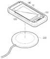
도 1은 본 발명의 바람직한 일 실시예에 따른 단말의 무선 충전 상태를 설명하기 위해 나타낸 사시도이고, 도 2는 케이스를 설명하기 위해 나타낸 분리도이다.FIG. 1 is a perspective view for explaining a wireless charging state of a terminal according to a preferred embodiment of the present invention, and FIG. 2 is a sectional view for explaining a case.
도시된 바와 같이 케이스(100)는 외부 충격으로부터 단말(10)을 보호하기 위한 수단인 동시에, 무선충전을 지원하지 아니한 단말로 하여금 무선 충전이 가능토록 하기 위한 수단으로 존재한다.As shown in the figure, the
이러한 케이스(100)는 단말(10) 배면을 보호하고 송신기(200)로부터 전력을 무선으로 공급받는 수신기(120)와 수신기를 통해 공급되는 전기 에너지가 저장되는 충전지(140)가 내재된 본체(110)와, 본체(110) 테두리에 마련되어 단말(10)의 외곽을 감싸 보호하고 수신기(120)와 충전포트(20)가 전기적으로 연결되도록 하는 커넥터(180)를 포함하여 구성된다.The
먼저, 커넥터(180)는 충전포트(20)에 대응하는 소켓 구조로서, 충전포트(20)와 탈착 가능하게 연결되어 수신기(120)와 배터리(30)가 전기적으로 연결되도록 하는 매개로서 존재한다.First, the
이러한 커넥터(180)는 인서트 사출을 통해 고정부(170)에 설치되는 것이며, 수신기(120)와는 전기적으로 연결된다.The
따라서 도시된 바와 같이 무선 충전을 지원하지 아니한 단말(10)로 하여금 무선충전이 가능토록 하는데 이에 대한 설명은 도 3을 참조하여 설명하도록 한다.Therefore, as shown in the figure, the terminal 10, which does not support wireless charging, is allowed to wirelessly charge. The description will be made with reference to FIG.
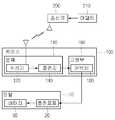
도 3은 본 발명의 바람직한 일 실시예에 따른 무선 충전 구조를 설명하기 위해 나타낸 개략도이다.FIG. 3 is a schematic view for explaining a wireless charging structure according to a preferred embodiment of the present invention.
도시된 바와 같이 케이스(100)는 송신기를 통해 무선으로 전기 에너지를 공급받는 수신기(120) 및 수신기(120)와 충전지를 포함하는 본체(110), 본체(110)와 전기적으로 연결된 커넥터(190)를 포함하며, 단말(10)은 충전포트(20) 및 충전포트(20)와 전기적으로 연결된 배터리(30)를 포함한다. 이때, 송신기(200)는 AC 전원과 연결된 어댑터(210)를 통해 전력을 유선으로 공급받는다.The
수신기(120)와 배터리(30)는 본체(110) 내에서 유선으로 연결되며, 서로 적층되거나, 나란하게 배치될 수 있다.The
이러한 수신기(120)를 통해 공급되는 전기 에너지는 충전지에 저장되고, 충전지(140)에 저장된 전기 에너지는 커넥터(190)와 탈착 가능하게 연결되는 충전포트(20)를 통해 단말(10)의 배터리(30)에 공급된다.The electric energy supplied through the
따라서 수신기(120)는 송신기(200)를 통해 송출되는 전력을 수신하고, 수신된 전력은 전기적으로 연결된 충전지에 저장되며, 저장된 전기 에너지는 커넥터(190) 및 충전포트(20)를 통해 배터리(30)에 저장되도록 함으로써, 결국 배터리(30)의 무선 충전이 가능토록 하였다.Thus, the
이로 인해, 무선 충전을 지원하지 아니한 단말에 대해서도 무선충전이 가능토록 하였으며, 특히, 케이스(100)를 통해 구현했다는 점은 본 발명의 특징을 이룬다.Accordingly, wireless charging is possible even for a terminal that does not support wireless charging. Particularly, the present invention is characterized in that it is realized through the
또한, 수신기(120)를 박형으로 구현하여 케이스(100)의 부피 비대를 예방함으로써, 상품성 향상과 더불어 편의성의 증대는 본 발명에서 가장 큰 특징을 이루며, 더욱이 케이스(100)에 보조 전력 수단으로 충전지(140)가 더 구비되어, 단말(10)의 배터리(30) 용량을 배가시키는 상승효과를 기대할 수 있다.In addition, since the
수신기(120)는 인서트 사출을 통해 본체(110)에 내재되거나, 또는 매립의 형태로 설치될 수 있으며, 이러한 설명은 도 4 내지 6을 참조하여 설명하도록 한다. 이때, 충전지(140)는 도시하지 않았으나, 도 2와 같이 수신기(120)와 단말(10) 사이에 위치하며, 수신기(120)와 함께 인서트 사출을 통해 본체(110)에 내재 되거나, 또는 매립의 형태로 설치될 수 있다.The
도 4는 본 발명의 바람직한 일 실시예에 다른 수신기를 설명하기 위해 나타낸 수신기의 횡단면도, 도 5는 수신기의 일례를 설명하기 위해 나타낸 수신기의 횡단면도, 도 6는 수신기의 설치 일례를 설명하기 위해 나타낸 횡단면도이다.FIG. 4 is a cross-sectional view of a receiver for explaining a receiver according to a preferred embodiment of the present invention, FIG. 5 is a cross-sectional view of the receiver shown for explaining an example of the receiver, and FIG. 6 is a cross- to be.
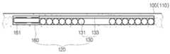
도시된 바와 같이 수신기(120)는 전력을 무선으로 수신하는 코일부(130)와, PCB(161)가 구비된 컨트롤부(160)를 포함하여 구성된다.As shown in the figure, the
이때, 컨트롤부(160)는 코일부(130)와 나란하게 배치되어 두께 형성에 직접 참여하지 아니하고 따라서 수신기(120)의 박형화가 가능토록 하였다. 또한, 코일부(130)와 컨트롤부(160)의 접촉면적을 최소화함으로써, 컨트롤부(160)에 대한 코일부(130)의 영향을 최소화하며, 따라서 작동효율의 향상을 기대할 수 있다. 즉, 나란한 배치를 통해 접촉부위를 최소화하여 전자기파에 의한 간섭을 줄이고, 그로 인한, 오작동 내지는 훼손 발생을 미연에 방지하여 기능저하를 예방할 수 있도록 하였다.At this time, the
코일부(130)는 도 3에 도시된 바와 같이 코일(131)과 자성체 시트(133)를 포함하며, 코일(131)과 자성체 시트(133)는 상/하 적층 배열된 구조를 이룬다.The
코일(131)은 무선 수신을 위한 것이며, 자성체 시트(133)는 전력을 수신하고, 상부로의 전력 누출을 차단해 줌으로써, 코일(131)에서 발생되는 자기장의 방향성을 극대화하는 역할을 수행한다. 즉, 송신기(200)를 통해 송출되는 전자기파의 방향을 유도하여 코일(131)에 집중되도록 하여 산란에 의한 손실이 최소화되도록 한 것이다.The
이러한 자성체 시트(133)는 재질로서 페라이트(ferrite)인 것이 바람직하나, 자성을 갖는 한 다른 재질로 대체 가능하다. 즉, 비정질 금속(amorphous metal), 연자성체 또는 강자성체를 재질로 하는 것도 가능하므로, 위 시트의 재질이 페라이트만으로 한정되지 아니한다.The
한편, 수신기(120)는 자성체 시트(133)에 금속성 플레이트(135)가 더 적층될 수 있으며, 이는 도 5를 참조하여 설명하도록 한다.On the other hand, the
도 5에 도시된 바와 같이 금속성 플레이트(135)는 자성체 시트(133)와 적층되어 도 5a와 같이 코일부(130)를 감싸거나, 또는 5b와 같이 코일부(130) 및 컨트롤부(160)를 함께 감싸도록 존재할 수 있으며, 또한 도시하지 않았으나, 코일부(130)와 컨트롤부(160) 각각에 분리된 구조로 존재할 수도 있다.5, the
이러한 금속성 플레이트(135)는 외부 충격에 의해 수신기(120)의 훼손을 방지하고, 내구성 향상 및 전자기파의 산란을 차폐하기 위한 것이다. 즉, 박형의 수신기(120)로 하여금 기계적 강도 보강은 물론, 충격에 의한 훼손을 방지하면서, 특히, 전자기파의 산란을 차폐하여 주변 전자기파(예를 들어, 블루투스(bluetooth) 내지는 와이파(wifi)이 등의 무선통신기파) 와의 간섭이 미연에 방지되도록 하였다.The
이때, 금속성 플레이트(135)는 스테인리스 스틸(STS, stainless steel)인 것이 바람직하나, 이에 한정되지 아니하며, 인청동 금, 은 동 또는 알루미늄 등으로 대체될 수 있다.At this time, it is preferable that the
한편, 금속성 플레이트(135)에 자성을 더 부여하기 위하여 자성체를 더 결합하거나, 그 일부 또는 전체에 걸쳐서 자성체를 더 코팅 할 수도 있는 데, 이는 무선 충전을 위한 전력 수신의 효율을 배가시키는 역할을 더 수행할수 있을 것으로 기대된다.On the other hand, in order to further impart magnetism to the
이와 같은 금속성 플레이트(135)에 자성을 부여하는 방식은 바람직하게는 코팅이 좋은데, 이는 금속성 플레이트(135)의 두께를 최대한 얇게 구성하기 위한 것이며, 따라서 비정질 금속 등을 코팅하는 방법에 의해 자성체 시트(133)와 결합할 수 있다.Such a method of imparting magnetism to the
이와 같이 비정질 금속을 코팅하는 경우는 예를 들어, 비정질 금속과 이종의 재질인 페라이트를 자성체 시트(133)로 사용하였을 때 적용하는 것이 좋다. 다만, 자성체 시트(133)로 비정질 금속을 사용하고, 금속성 플레이트(135)에 자성을 더 부여하기 위하여 비정질 금속을 코팅하는 것은 비정질 금속을 금속성 플레이트(135) 상에 이중으로 코팅하는 것이며, 이를 공정상 배제하는 것은 아니다.In the case of coating the amorphous metal in this way, it is preferable to apply it when, for example, ferrite which is a material different from amorphous metal is used as the
이상과 같이 수신기(120)는 인서트 사출을 통해 케이스(100)에 내재되어 외부 전력을 무선으로 수신가는 기능을 수행하거나, 또는, 도 6에 도시된 바와 같이 미리 형성된 매립홈(111)을 통해 케이스(100)에 내재될 수 있는데 이는 도 6을 참조하여 설명하도록 한다.As described above, the
도시된 바와 같이 수신기(120)는 케이스(100)에 미리 형성된 매립홈(111)에 코일(131)과 자성체 시트(133)가 순차적으로 적층된 코일부(130) 및 코일부(130) 측면에 컨트롤부(160)가 나란하게 안착되며, 개방된 상부는 외관부(160)에 의해 밀폐된다. 이때, 수신기(120)에서 도시하지 않았으나, 도 5와 같이 금속성 플레이트(135)가 더 존재할 수도 있다.The
외관부(160)는 부착되는 필름, 페인팅, 증착에 의한 코팅체 중 선택되는 어느 하나인 것이 바람직하며, 그 중 필름인 것이 바람직하다.The
필름의 재질로는 PC(Polycarbonate), PI(Polyimide) 및 PET(Polyethylene Terephtalate) 중 선택되는 어느 하나이거나, 적어도 하나의 조합인 것이 바람직하다.The material of the film may be any one selected from among PC (Polycarbonate), PI (Polyimide) and PET (Polyethylene Terephthalate), or a combination of at least one thereof.
한편, 수신기(120)는 모듈로서 존재하여 도 7과 같이 사출에 의해 미리 제작될 수도 있는데 이에 대한 설명은 도 7을 참조하여 설명하도록 한다.Meanwhile, the
도 7은 본 발명의 바람직한 일 실시예에 따른 수신기의 다른 일례를 설명하기 위해 나타낸 횡단면도이다.7 is a cross-sectional view illustrating another example of a receiver according to a preferred embodiment of the present invention.
도시된 바와 같이 수신기(120)는 사출부(150)에 의해 모듈로 미리 제작될 수 있다. 이러한 수신기(120)는 코일부(130)를 모체로 하여 성형하는 제1사출부(151), 코일부(130)의 측면에 배치되는 컨트롤부(160)를 모체로하여 컨트롤부(160)를 감싸듯 성형하는 제2사출부(153)를 포함하며, 이때, 제1사출부(151)와 제2사출부(153)는 인서트 사출에 의한 성형인 것이 바람직하다.As shown, the
이와 같이 코일부(130)를 모체로 하는 인서트 사출을 진행함으로써, 코일부(130)의 모듈화가 가능하며, 적어도 코일부(130)가 불량일 경우, 교체의 범위를 최소화시킬 수 있는 경제적 효과를 기대할 수 있다. 즉 종래에는 코일부 또는 컨트롤부의 오류 발생 시 전 구성요소들이 적층 구조이므로 모두에 대해서 교체할 수밖에 없었으나, 본 발명에 의하면 병렬관계이므로 병렬구조중 어느 하나를 교체하는 것이 가능할 수 있다. 따라서 장치 유치의 경제성이 예상된다.By performing the insert injection using the
도 8은 본 발명의 바람직한 일 실시예에 따른 컨트롤부의 구성 형태를 설명하기 위해 나타낸 평면도이다.8 is a plan view illustrating a configuration of a control unit according to a preferred embodiment of the present invention.
도시된 바와 같이, 본 발명의 컨트롤부(160)는 코일부(130)의 일측에 나란히 설치될 수 있으며(a), 특히 코일부(130)를 중심으로 방사형으로 설치되는 것(b)도 가능하다. 그러나, 이러한 두가지의 실시양태는 모두 코일부(130)를 중심으로 하여 그 측면에 컨트롤부(160)를 마련한다는 점에서 공통성을 가지며, 구성의 형태가 다소 다를 뿐이다.The
이상에서 실시예를 들어 본 발명을 더욱 상세하게 설명하였으나, 본 발명은 반드시 이러한 실시예로 국한되는 것이 아니고 본 발명의 기술사상을 벗어나지 않는 범위 내에서 다양하게 변형실시될 수 있다. 따라서, 본 발명에 개시된 실시예는 본 발명의 기술 사상을 한정하기 위한 것이 아니라 설명하기 위한 것이고, 이러한 실시예에 의하여 본 발명의 기술 사상의 범위가 안정되는 것은 아니다. 본 발명의 보호 범위는 아래의 청구범위에 의하여 해석되어야 하며, 그와 동등한 범위 내에 있는 모든 기술 사상은 본 발명의 권리범위에 포함되는 것으로 해석되어야 할 것이다.While the present invention has been particularly shown and described with reference to exemplary embodiments thereof, it is to be understood that the invention is not limited to the disclosed exemplary embodiments. Therefore, the embodiments disclosed in the present invention are intended to illustrate rather than limit the scope of the present invention, and the scope of the technical idea of the present invention is not limited by these embodiments. The scope of protection of the present invention should be construed according to the following claims, and all technical ideas within the scope of equivalents should be construed as falling within the scope of the present invention.
10 : 단말 20 : 충전포트
30 : 배터리 100 : 케이스
110 : 본체 111 : 매립홈
120 : 수신기 130 : 코일부
131 : 코일 133 : 자성체 시트
135 : 금속성 플레이트 140 : 충전지
150 : 사출부 151 : 제1사출부
153 : 제2사출부 160 : 컨트롤부
161 : PCB 170 : 외관부
180 : 고정부 190 : 커넥터
200 : 송신기 210 : 어댑터10: Terminal 20: Charging port
30: Battery 100: Case
110: main body 111: buried groove
120: receiver 130:
131: coil 133: magnetic substance sheet
135: metallic plate 140: rechargeable battery
150: injection part 151: first injection part
153: second injection part 160: control part
161: PCB 170:
180: fixing part 190: connector
200: Transmitter 210: Adapter
Claims (13)
Translated fromKorean상기 본체에 내재되어 무선 충전용 송신기로부터 전력을 무선으로 공급받는 수신기;
상기 본체에 내재 되고 상기 수신기와 전기적으로 연결되며, 상기 수신기로 공급되는 전기 에너지가 저장되는 충전지; 및
상기 고정부에 마련되고 상기 수신기와 전기적으로 연결되며, 상기 단말의 충전포트가 탈착 가능하게 결합되는 커넥터;를 포함하며,
상기 수신기는, 코일 및 자성체시트가 상/하 적층 배열된 코일부와 컨트롤부를 포함하여 구성된 것을 특징으로 하는 무선 충전용 수신기가 구비된 단말용 케이스.A case including a main body for protecting a back surface of a terminal and a fixing part provided on an edge of the main body to surround and protect the outside of the terminal,
A receiver included in the main body and supplied with power wirelessly from a wireless charging transmitter;
A rechargeable battery contained in the main body and electrically connected to the receiver, the rechargeable battery storing electrical energy supplied to the receiver; And
And a connector provided in the fixing part and electrically connected to the receiver, the connector being detachably coupled to the charging port of the terminal,
Wherein the receiver includes a coil portion and a control portion, the coil portion and the magnetic substance sheet being stacked in an up-down direction, and a control portion.
상기 케이스는,
상기 수신기와 충전기 및 커넥터를 매개로 인서트 사출되거나, 적어도 상기 수신기는 상기 본체 일면에 형성된 매립홈을 통해 내설되는 것을 특징으로 하는 무선 충전용 수신기가 구비된 단말용 케이스.The method according to claim 1,
In this case,
Wherein the at least one receiver is inserted through the receiver, the charger, and the connector, or at least the receiver is installed through a buried groove formed on one side of the main body.
상기 코일부는,
상기 매립홈을 통해 상기 본체에 내설될 경우, 상기 코일 그리고 자성체 시트가 상기 매립홈에 안착되고, 상기 매립홈은 외관부에 의해 밀폐되는 것을 특징으로 하는 무선 충전용 수신기가 구비된 단말용 케이스.3. The method of claim 2,
Wherein the coil portion includes:
Wherein the coil and the magnetic substance sheet are seated in the buried groove and the buried groove is sealed by an outer tube when the body is inserted into the body through the buried groove.
상기 외관부는,
부착되는 필름, 페인팅 또는 증착에 의한 코팅체, 또는 인서트 사출물인 것을 특징으로 하는 무선 충전용 수신기가 구비된 단말용 케이스.The method of claim 3,
The outer-
Wherein the base case is a film to be attached, a coating body by painting or vapor deposition, or an insert injection.
상기 필름은,
PC(Polycarbonate), PI(Polyimide) 또는 PET(Polyethylene Terephtalate) 재질인 것을 특징으로 하는 무선 충전용 수신기가 구비된 단말용 케이스.5. The method of claim 4,
The film may be,
Wherein the antenna is made of PC (Polycarbonate), PI (Polyimide) or PET (Polyethylene Terephtalate).
상기 컨트롤부는,
상기 코일부와 나란하게 배치되며, 적어도 외주면에 사출부가 더 형성되는 것을 특징으로 하는 무선 충전용 수신기가 구비된 단말용 케이스.The method according to claim 1,
The control unit includes:
Wherein the casing is disposed in parallel with the coil part, and an injection part is further formed on at least an outer circumferential surface thereof.
상기 자성체 시트는, 페라이트, 비정질 금속(amorphous metal), 연자성체 또는 강자성체를 재질로 하는 것을 특징으로 하는 무선 충전용 수신기가 구비된 단말용 케이스.The method according to claim 1,
Wherein the magnetic substance sheet is made of ferrite, amorphous metal, soft magnetic material, or ferromagnetic material.
상기 수신기는,
상기 코일 및 자성체 시트 사이 또는 어느 일면에 금속성 플레이트가 더 배치되며,
상기 금속성 플레이트는, 서스(SUS), 인청동, 알루미늄, 금, 은 및 동 중 선택되는 적어도 하나의 재질로 하는 것을 특징으로 하는 무선 충전용 수신기가 구비된 단말용 케이스.The method according to claim 1,
The receiver includes:
A metallic plate is further disposed between the coil and the magnetic substance sheet or on one surface thereof,
Wherein the metallic plate is made of at least one material selected from SUS, phosphor bronze, aluminum, gold, silver and copper.
상기 금속성 플레이트의 일부 또는 전체에 자성재료가 코팅, 증착 또는 페인팅되는 것을 특징으로 하는 무선 충전용 수신기가 구비된 단말용 케이스.9. The method of claim 8,
Wherein a magnetic material is coated, deposited or painted on a part or the whole of the metallic plate.
상기 자성재료는, 비정질 금속인 것을 특징으로 하는 무선 충전용 수신기가 구비된 단말용 케이스.10. The method of claim 9,
Wherein the magnetic material is an amorphous metal.
상기 코일부는,
상기 코일과 자성체 시트 또는 코일과 자성체 시트 및 금속성 플레이트는 인서트 사출에 의해 모듈로 구성되는 것을 특징으로 하는 무선 충전용 수신기가 구비된 단말용 케이스.9. The method of claim 8,
Wherein the coil portion includes:
Wherein the coil and the magnetic substance sheet, or the coil, the magnetic substance sheet and the metallic plate are formed by a module by insert injection.
상기 금속성 플레이트는,
상기 컨트롤부까지 연장되어 설치되거나, 상기 컨트롤부에 더 설치되는 것을 특징으로 하는 무선 충전용 수신기가 구비된 단말용 케이스.9. The method of claim 8,
Wherein the metallic plate comprises:
Wherein the control unit is further provided with a control unit, and the control unit is further provided with the control unit.
상기 컨트롤부는,
상기 코일부의 측면 일측에 나란하게 배치되거나, 코일부의 외주부를 둘러싼 형태로 형성되는 것을 특징으로 하는 무선 충전용 수신기가 구비된 단말용 케이스.The method according to claim 1,
The control unit includes:
Wherein the case is disposed in parallel to one side of the side face of the coil part or surrounding the outer periphery of the coil part.
Priority Applications (1)
| Application Number | Priority Date | Filing Date | Title |
|---|---|---|---|
| KR1020160010238AKR101901455B1 (en) | 2016-01-27 | 2016-01-27 | Device case with Rx of wireless charging |
Applications Claiming Priority (1)
| Application Number | Priority Date | Filing Date | Title |
|---|---|---|---|
| KR1020160010238AKR101901455B1 (en) | 2016-01-27 | 2016-01-27 | Device case with Rx of wireless charging |
Publications (2)
| Publication Number | Publication Date |
|---|---|
| KR20170089687Atrue KR20170089687A (en) | 2017-08-04 |
| KR101901455B1 KR101901455B1 (en) | 2018-09-21 |
Family
ID=59654294
Family Applications (1)
| Application Number | Title | Priority Date | Filing Date |
|---|---|---|---|
| KR1020160010238AExpired - Fee RelatedKR101901455B1 (en) | 2016-01-27 | 2016-01-27 | Device case with Rx of wireless charging |
Country Status (1)
| Country | Link |
|---|---|
| KR (1) | KR101901455B1 (en) |
Cited By (4)
| Publication number | Priority date | Publication date | Assignee | Title |
|---|---|---|---|---|
| CN109245320A (en)* | 2018-08-09 | 2019-01-18 | 广州华夏职业学院 | A kind of non-contact wireless mobile phone charger |
| KR20190028868A (en)* | 2017-09-11 | 2019-03-20 | 신승민 | Smart distribution box for preventing an electric shock |
| KR20200130098A (en) | 2019-05-08 | 2020-11-18 | 장홍민 | Card type Wireless Charger |
| WO2023201579A1 (en)* | 2022-04-20 | 2023-10-26 | 前海骏达(深圳)股权投资有限公司 | Support |
Family Cites Families (1)
| Publication number | Priority date | Publication date | Assignee | Title |
|---|---|---|---|---|
| KR101230877B1 (en)* | 2011-03-30 | 2013-02-07 | 주식회사 케이에이치바텍 | Wireless charger for portable device |
- 2016
- 2016-01-27KRKR1020160010238Apatent/KR101901455B1/ennot_activeExpired - Fee Related
Cited By (6)
| Publication number | Priority date | Publication date | Assignee | Title |
|---|---|---|---|---|
| KR20190028868A (en)* | 2017-09-11 | 2019-03-20 | 신승민 | Smart distribution box for preventing an electric shock |
| CN111093420A (en)* | 2017-09-11 | 2020-05-01 | 株式会社为德克伦驰 | Portable terminal protective sleeve with built-in auxiliary battery |
| CN109245320A (en)* | 2018-08-09 | 2019-01-18 | 广州华夏职业学院 | A kind of non-contact wireless mobile phone charger |
| CN109245320B (en)* | 2018-08-09 | 2021-06-01 | 广州华夏职业学院 | Non-contact wireless mobile phone charger |
| KR20200130098A (en) | 2019-05-08 | 2020-11-18 | 장홍민 | Card type Wireless Charger |
| WO2023201579A1 (en)* | 2022-04-20 | 2023-10-26 | 前海骏达(深圳)股权投资有限公司 | Support |
Also Published As
| Publication number | Publication date |
|---|---|
| KR101901455B1 (en) | 2018-09-21 |
Similar Documents
| Publication | Publication Date | Title |
|---|---|---|
| KR101738073B1 (en) | Support for phone including wireless charging device | |
| US11108271B2 (en) | Electronic device including multiple coils | |
| US9667085B2 (en) | Wireless charger for electronic device | |
| KR101901455B1 (en) | Device case with Rx of wireless charging | |
| CN111527666B (en) | wireless power transmission device | |
| EP2529469B1 (en) | Modular pocket with inductive power and data | |
| US8878486B2 (en) | Battery pack for charging a mobile terminal by receiving electric power from an external charger, and a mobile terminal with the same | |
| US8633616B2 (en) | Modular pocket with inductive power and data | |
| KR20120117262A (en) | Wireless power transmission device for vehicle | |
| EP3061175B1 (en) | Wireless power transmitter | |
| JP2012517206A (en) | Retrofitting wireless power and near field communication in electronic devices | |
| KR100792312B1 (en) | Outer case of portable electronic device with contactless charging circuit and its electronic device | |
| KR101701054B1 (en) | Wireless charging device for vehicle | |
| EP2890020B1 (en) | Male connector, female connector, and connection structure of male connector and female connector | |
| KR20130076067A (en) | Mobile capable of operating wireless charge and near field communication | |
| KR101956536B1 (en) | Wireless charging support accessory attached and separated from user terminal and wireless charging system based the same | |
| CN112448421B (en) | Structure of wrist annular chargeable energy storage battery and external charging device | |
| KR20150145959A (en) | Wireless charger | |
| KR20170035186A (en) | Wireless charging module | |
| JP2014087188A (en) | Portable device and its built-in battery pack | |
| KR20230112312A (en) | Magnet assembly for mobile terminal and wireless charging device combined therewith | |
| JP2015002580A (en) | Wireless charging device | |
| JP2022026100A (en) | Electronic apparatus and non-contact charging system | |
| KR20230071658A (en) | Battery pack device that has both of transmitter and receiver functions of wireless power transfer |
Legal Events
| Date | Code | Title | Description |
|---|---|---|---|
| A201 | Request for examination | ||
| PA0109 | Patent application | St.27 status event code:A-0-1-A10-A12-nap-PA0109 | |
| PA0201 | Request for examination | St.27 status event code:A-1-2-D10-D11-exm-PA0201 | |
| D13-X000 | Search requested | St.27 status event code:A-1-2-D10-D13-srh-X000 | |
| D14-X000 | Search report completed | St.27 status event code:A-1-2-D10-D14-srh-X000 | |
| PG1501 | Laying open of application | St.27 status event code:A-1-1-Q10-Q12-nap-PG1501 | |
| E902 | Notification of reason for refusal | ||
| PE0902 | Notice of grounds for rejection | St.27 status event code:A-1-2-D10-D21-exm-PE0902 | |
| E13-X000 | Pre-grant limitation requested | St.27 status event code:A-2-3-E10-E13-lim-X000 | |
| P11-X000 | Amendment of application requested | St.27 status event code:A-2-2-P10-P11-nap-X000 | |
| P13-X000 | Application amended | St.27 status event code:A-2-2-P10-P13-nap-X000 | |
| E90F | Notification of reason for final refusal | ||
| PE0902 | Notice of grounds for rejection | St.27 status event code:A-1-2-D10-D21-exm-PE0902 | |
| P11-X000 | Amendment of application requested | St.27 status event code:A-2-2-P10-P11-nap-X000 | |
| P13-X000 | Application amended | St.27 status event code:A-2-2-P10-P13-nap-X000 | |
| E701 | Decision to grant or registration of patent right | ||
| PE0701 | Decision of registration | St.27 status event code:A-1-2-D10-D22-exm-PE0701 | |
| GRNT | Written decision to grant | ||
| PR0701 | Registration of establishment | St.27 status event code:A-2-4-F10-F11-exm-PR0701 | |
| PR1002 | Payment of registration fee | St.27 status event code:A-2-2-U10-U11-oth-PR1002 Fee payment year number:1 | |
| PG1601 | Publication of registration | St.27 status event code:A-4-4-Q10-Q13-nap-PG1601 | |
| P22-X000 | Classification modified | St.27 status event code:A-4-4-P10-P22-nap-X000 | |
| P22-X000 | Classification modified | St.27 status event code:A-4-4-P10-P22-nap-X000 | |
| PC1903 | Unpaid annual fee | St.27 status event code:A-4-4-U10-U13-oth-PC1903 Not in force date:20210918 Payment event data comment text:Termination Category : DEFAULT_OF_REGISTRATION_FEE | |
| PC1903 | Unpaid annual fee | St.27 status event code:N-4-6-H10-H13-oth-PC1903 Ip right cessation event data comment text:Termination Category : DEFAULT_OF_REGISTRATION_FEE Not in force date:20210918 | |
| R18-X000 | Changes to party contact information recorded | St.27 status event code:A-5-5-R10-R18-oth-X000 | |
| P22-X000 | Classification modified | St.27 status event code:A-4-4-P10-P22-nap-X000 |