KR20170089340A - Flexible sensor module and manufacturing method thereof - Google Patents
Flexible sensor module and manufacturing method thereofDownload PDFInfo
- Publication number
- KR20170089340A KR20170089340AKR1020160009628AKR20160009628AKR20170089340AKR 20170089340 AKR20170089340 AKR 20170089340AKR 1020160009628 AKR1020160009628 AKR 1020160009628AKR 20160009628 AKR20160009628 AKR 20160009628AKR 20170089340 AKR20170089340 AKR 20170089340A
- Authority
- KR
- South Korea
- Prior art keywords
- solar cell
- substrate
- metal electrode
- sensor unit
- compound layer
- Prior art date
- Legal status (The legal status is an assumption and is not a legal conclusion. Google has not performed a legal analysis and makes no representation as to the accuracy of the status listed.)
- Ceased
Links
Images


Classifications
- G—PHYSICS
- G01—MEASURING; TESTING
- G01N—INVESTIGATING OR ANALYSING MATERIALS BY DETERMINING THEIR CHEMICAL OR PHYSICAL PROPERTIES
- G01N33/00—Investigating or analysing materials by specific methods not covered by groups G01N1/00 - G01N31/00
- H—ELECTRICITY
- H01—ELECTRIC ELEMENTS
- H01M—PROCESSES OR MEANS, e.g. BATTERIES, FOR THE DIRECT CONVERSION OF CHEMICAL ENERGY INTO ELECTRICAL ENERGY
- H01M10/00—Secondary cells; Manufacture thereof
- H01M10/42—Methods or arrangements for servicing or maintenance of secondary cells or secondary half-cells
- H01M10/46—Accumulators structurally combined with charging apparatus
- H01M10/465—Accumulators structurally combined with charging apparatus with solar battery as charging system
- G—PHYSICS
- G01—MEASURING; TESTING
- G01D—MEASURING NOT SPECIALLY ADAPTED FOR A SPECIFIC VARIABLE; ARRANGEMENTS FOR MEASURING TWO OR MORE VARIABLES NOT COVERED IN A SINGLE OTHER SUBCLASS; TARIFF METERING APPARATUS; MEASURING OR TESTING NOT OTHERWISE PROVIDED FOR
- G01D11/00—Component parts of measuring arrangements not specially adapted for a specific variable
- G01D11/30—Supports specially adapted for an instrument; Supports specially adapted for a set of instruments
- G—PHYSICS
- G01—MEASURING; TESTING
- G01N—INVESTIGATING OR ANALYSING MATERIALS BY DETERMINING THEIR CHEMICAL OR PHYSICAL PROPERTIES
- G01N33/00—Investigating or analysing materials by specific methods not covered by groups G01N1/00 - G01N31/00
- G01N33/0004—Gaseous mixtures, e.g. polluted air
- G—PHYSICS
- G08—SIGNALLING
- G08C—TRANSMISSION SYSTEMS FOR MEASURED VALUES, CONTROL OR SIMILAR SIGNALS
- G08C17/00—Arrangements for transmitting signals characterised by the use of a wireless electrical link
- G08C17/02—Arrangements for transmitting signals characterised by the use of a wireless electrical link using a radio link
- H01L31/02168—
- H01L31/022425—
- H01L31/03046—
- H01L31/04—
- H01L31/048—
- H01L31/18—
- H—ELECTRICITY
- H02—GENERATION; CONVERSION OR DISTRIBUTION OF ELECTRIC POWER
- H02J—CIRCUIT ARRANGEMENTS OR SYSTEMS FOR SUPPLYING OR DISTRIBUTING ELECTRIC POWER; SYSTEMS FOR STORING ELECTRIC ENERGY
- H02J7/00—Circuit arrangements for charging or depolarising batteries or for supplying loads from batteries
- H02J7/34—Parallel operation in networks using both storage and other DC sources, e.g. providing buffering
- H02J7/35—Parallel operation in networks using both storage and other DC sources, e.g. providing buffering with light sensitive cells
- H—ELECTRICITY
- H04—ELECTRIC COMMUNICATION TECHNIQUE
- H04Q—SELECTING
- H04Q9/00—Arrangements in telecontrol or telemetry systems for selectively calling a substation from a main station, in which substation desired apparatus is selected for applying a control signal thereto or for obtaining measured values therefrom
- H—ELECTRICITY
- H10—SEMICONDUCTOR DEVICES; ELECTRIC SOLID-STATE DEVICES NOT OTHERWISE PROVIDED FOR
- H10F—INORGANIC SEMICONDUCTOR DEVICES SENSITIVE TO INFRARED RADIATION, LIGHT, ELECTROMAGNETIC RADIATION OF SHORTER WAVELENGTH OR CORPUSCULAR RADIATION
- H10F19/00—Integrated devices, or assemblies of multiple devices, comprising at least one photovoltaic cell covered by group H10F10/00, e.g. photovoltaic modules
- H10F19/80—Encapsulations or containers for integrated devices, or assemblies of multiple devices, having photovoltaic cells
- H—ELECTRICITY
- H10—SEMICONDUCTOR DEVICES; ELECTRIC SOLID-STATE DEVICES NOT OTHERWISE PROVIDED FOR
- H10F—INORGANIC SEMICONDUCTOR DEVICES SENSITIVE TO INFRARED RADIATION, LIGHT, ELECTROMAGNETIC RADIATION OF SHORTER WAVELENGTH OR CORPUSCULAR RADIATION
- H10F71/00—Manufacture or treatment of devices covered by this subclass
- H10F71/127—The active layers comprising only Group III-V materials, e.g. GaAs or InP
- H—ELECTRICITY
- H10—SEMICONDUCTOR DEVICES; ELECTRIC SOLID-STATE DEVICES NOT OTHERWISE PROVIDED FOR
- H10F—INORGANIC SEMICONDUCTOR DEVICES SENSITIVE TO INFRARED RADIATION, LIGHT, ELECTROMAGNETIC RADIATION OF SHORTER WAVELENGTH OR CORPUSCULAR RADIATION
- H10F77/00—Constructional details of devices covered by this subclass
- H10F77/20—Electrodes
- H10F77/206—Electrodes for devices having potential barriers
- H10F77/211—Electrodes for devices having potential barriers for photovoltaic cells
- H—ELECTRICITY
- H10—SEMICONDUCTOR DEVICES; ELECTRIC SOLID-STATE DEVICES NOT OTHERWISE PROVIDED FOR
- H10F—INORGANIC SEMICONDUCTOR DEVICES SENSITIVE TO INFRARED RADIATION, LIGHT, ELECTROMAGNETIC RADIATION OF SHORTER WAVELENGTH OR CORPUSCULAR RADIATION
- H10F77/00—Constructional details of devices covered by this subclass
- H10F77/90—Energy storage means directly associated or integrated with photovoltaic cells, e.g. capacitors integrated with photovoltaic cells
- H—ELECTRICITY
- H01—ELECTRIC ELEMENTS
- H01L—SEMICONDUCTOR DEVICES NOT COVERED BY CLASS H10
- H01L25/00—Assemblies consisting of a plurality of semiconductor or other solid state devices
- H01L25/16—Assemblies consisting of a plurality of semiconductor or other solid state devices the devices being of types provided for in two or more different subclasses of H10B, H10D, H10F, H10H, H10K or H10N, e.g. forming hybrid circuits
- H—ELECTRICITY
- H04—ELECTRIC COMMUNICATION TECHNIQUE
- H04Q—SELECTING
- H04Q2209/00—Arrangements in telecontrol or telemetry systems
- H04Q2209/40—Arrangements in telecontrol or telemetry systems using a wireless architecture
- H—ELECTRICITY
- H04—ELECTRIC COMMUNICATION TECHNIQUE
- H04Q—SELECTING
- H04Q2209/00—Arrangements in telecontrol or telemetry systems
- H04Q2209/80—Arrangements in the sub-station, i.e. sensing device
- H04Q2209/88—Providing power supply at the sub-station
- H04Q2209/886—Providing power supply at the sub-station using energy harvesting, e.g. solar, wind or mechanical
- Y—GENERAL TAGGING OF NEW TECHNOLOGICAL DEVELOPMENTS; GENERAL TAGGING OF CROSS-SECTIONAL TECHNOLOGIES SPANNING OVER SEVERAL SECTIONS OF THE IPC; TECHNICAL SUBJECTS COVERED BY FORMER USPC CROSS-REFERENCE ART COLLECTIONS [XRACs] AND DIGESTS
- Y02—TECHNOLOGIES OR APPLICATIONS FOR MITIGATION OR ADAPTATION AGAINST CLIMATE CHANGE
- Y02E—REDUCTION OF GREENHOUSE GAS [GHG] EMISSIONS, RELATED TO ENERGY GENERATION, TRANSMISSION OR DISTRIBUTION
- Y02E10/00—Energy generation through renewable energy sources
- Y02E10/50—Photovoltaic [PV] energy
- Y02E10/544—Solar cells from Group III-V materials
- Y—GENERAL TAGGING OF NEW TECHNOLOGICAL DEVELOPMENTS; GENERAL TAGGING OF CROSS-SECTIONAL TECHNOLOGIES SPANNING OVER SEVERAL SECTIONS OF THE IPC; TECHNICAL SUBJECTS COVERED BY FORMER USPC CROSS-REFERENCE ART COLLECTIONS [XRACs] AND DIGESTS
- Y02—TECHNOLOGIES OR APPLICATIONS FOR MITIGATION OR ADAPTATION AGAINST CLIMATE CHANGE
- Y02E—REDUCTION OF GREENHOUSE GAS [GHG] EMISSIONS, RELATED TO ENERGY GENERATION, TRANSMISSION OR DISTRIBUTION
- Y02E60/00—Enabling technologies; Technologies with a potential or indirect contribution to GHG emissions mitigation
- Y02E60/10—Energy storage using batteries
- Y—GENERAL TAGGING OF NEW TECHNOLOGICAL DEVELOPMENTS; GENERAL TAGGING OF CROSS-SECTIONAL TECHNOLOGIES SPANNING OVER SEVERAL SECTIONS OF THE IPC; TECHNICAL SUBJECTS COVERED BY FORMER USPC CROSS-REFERENCE ART COLLECTIONS [XRACs] AND DIGESTS
- Y02—TECHNOLOGIES OR APPLICATIONS FOR MITIGATION OR ADAPTATION AGAINST CLIMATE CHANGE
- Y02P—CLIMATE CHANGE MITIGATION TECHNOLOGIES IN THE PRODUCTION OR PROCESSING OF GOODS
- Y02P70/00—Climate change mitigation technologies in the production process for final industrial or consumer products
- Y02P70/50—Manufacturing or production processes characterised by the final manufactured product
Landscapes
- Engineering & Computer Science (AREA)
- Life Sciences & Earth Sciences (AREA)
- Computer Networks & Wireless Communication (AREA)
- Chemical & Material Sciences (AREA)
- Power Engineering (AREA)
- Sustainable Development (AREA)
- Sustainable Energy (AREA)
- General Physics & Mathematics (AREA)
- Physics & Mathematics (AREA)
- Manufacturing & Machinery (AREA)
- General Chemical & Material Sciences (AREA)
- Electrochemistry (AREA)
- Chemical Kinetics & Catalysis (AREA)
- Testing Or Calibration Of Command Recording Devices (AREA)
- Health & Medical Sciences (AREA)
- Medicinal Chemistry (AREA)
- Food Science & Technology (AREA)
- Analytical Chemistry (AREA)
- Biochemistry (AREA)
- General Health & Medical Sciences (AREA)
- Immunology (AREA)
- Pathology (AREA)
- Combustion & Propulsion (AREA)
Abstract
Translated fromKoreanDescription
Translated fromKorean본 발명은 태양 전지를 포함하는 센서 모듈 및 이의 제조 방법에 관한 것이다.The present invention relates to a sensor module including a solar cell and a manufacturing method thereof.
온도, 습도, 가스 농도, 조도 등 다양한 정보를 센싱할 수 있는 장치의 활용성을 높이기 위해서는 다양한 센서를 포함하여 집적화시킨 센서 모듈의 제작이 요구된다. 센서 모듈이란, 센서부, 전원부, 통신부 등이 일체화되도록 구성되는 장치를 의미한다.In order to increase the usability of devices that can sense various information such as temperature, humidity, gas concentration, and illumination, it is required to manufacture an integrated sensor module including various sensors. The sensor module means a device configured to integrate a sensor unit, a power source unit, a communication unit, and the like.
센서 모듈에 포함되는 각각의 센서를 작동시키기 위해서는 별도의 에너지원이 필요하고, 일반적으로는 1차 전지인 화학 전지가 사용하여 구성되었다. 화학 전지는 주기적인 충전이나 교체가 요구되므로, 사용 편의성이 떨어지는 문제점이 있고 이러한 문제점을 해결하기 위해 별도의 교체나 에너지의 충전이 불필요한 태양 전지를 포함시켜 센서 모듈을 구성할 수 있다. 다만, 태양 전지를 센서 모듈의 에너지원으로 이용하기 위해서는 고효율의 태양 전지가 필요하고, 태양 전지를 내부에 포함되면, 센서 모듈의 크기가 커지는 문제점이 있다. 센서 모듈의 크기가 커지게 되면, 설치되는 장소에 제약을 받게 되는 문제점이 생기게 된다.In order to operate each sensor included in the sensor module, a separate energy source is required. In general, a chemical battery, which is a primary battery, is used. Since the chemical battery is required to be periodically charged or replaced, there is a problem in that it is not easy to use. In order to solve such a problem, a sensor module including a solar cell which does not require additional replacement or energy charging can be constructed. However, in order to use the solar cell as an energy source of the sensor module, a highly efficient solar cell is required. When the solar cell is included in the sensor module, the size of the sensor module becomes large. When the size of the sensor module becomes large, there arises a problem that it is restricted in the installation place.
이에 센서 모듈이 집적화되어 크기가 커지지 않으며, 유연한 특성을 가져 곡면에도 설치될 수 있는 특성을 가지는 새로운 구조를 가지는 센서 모듈의 필요성이 요구된다.Therefore, there is a need for a sensor module having a new structure having characteristics that the sensor module is integrated and does not increase in size, and has a flexible characteristic and can be installed on a curved surface.
본 발명은 센서 모듈의 구동을 위해 에너지를 공급할 수 있는 태양 전지를 포함하는 플렉서블 센서 모듈을 제안하기 위한 것이다.The present invention proposes a flexible sensor module including a solar cell capable of supplying energy for driving a sensor module.
또한, 본 발명은 플렉서블 센서 모듈이 집적화될 수 있는 새로운 구조를 제안하기 위한 것이다.In addition, the present invention is intended to propose a new structure in which a flexible sensor module can be integrated.
또한, 본 발명은 상기와 같은 구조를 가지는 플렉서블 센서 모듈을 제조하는 방법을 제안하기 위한 것이다.In addition, the present invention proposes a method of manufacturing a flexible sensor module having the above structure.
상기와 과제를 실현하기 위한 본 발명의 일 실시예와 관련된 플렉서블 센서 모듈은, 제1 기판 위에서 외부의 환경 정보의 측정을 위하여 외부에 노출되도록 위치되는 센서부; 상기 센서부와 나란하게 배치되고, 빛을 받아 전원을 생성하는 태양 전지; 상기 제1 기판 위의 일 측에 위치되고, 상기 센서부로부터 측정된 정보를 외부 서버로 전송하는 무선 통신부; 및 상기 제1 기판 위의 다른 일 측에 위치되고, 상기 태양 전지로부터 전원을 공급받아 충전되며, 충전된 전원을 상기 센서부 및 상기 무선 통신부에 공급하는 화학 전지를 포함하고, 상기 태양 전지는, 제2 기판 위에 위치되고, 빛을 받아 상기 센서부에 공급되는 전원을 생성하는 화합물층; 및 상기 화합물층의 표면에 형성되는 금속 전극을 포함한다.According to an embodiment of the present invention, there is provided a flexible sensor module including: a sensor unit positioned on a first substrate so as to be exposed to the outside for measurement of external environmental information; A solar cell disposed in parallel to the sensor unit and receiving light to generate power; A wireless communication unit located on one side of the first substrate and transmitting information measured by the sensor unit to an external server; And a chemical battery located on the other side of the first substrate and supplied with power from the solar cell and supplying the charged power to the sensor unit and the wireless communication unit, A compound layer which is positioned on the second substrate and generates power to be supplied to the sensor unit by receiving light; And a metal electrode formed on the surface of the compound layer.
본 발명과 관련된 일 예에 따르면, 상기 센서부, 태양 전지, 무선 통신부 및 화학 전지는, 상기 제1 기판 위의 서로 다른 위치에 각각 배치된다.According to an embodiment of the present invention, the sensor unit, the solar cell, the wireless communication unit, and the chemical battery are disposed at different positions on the first substrate.
본 발명과 관련된 일 예에 따르면, 상기 태양 전지는, 외부에 노출되어 빛을 흡수하도록, 상기 무선 통신부 및 상기 화학 전지 중 적어도 하나 위에 위치될 수 있다.According to one example related to the present invention, the solar cell may be positioned on at least one of the wireless communication unit and the chemical battery so as to be exposed to the outside to absorb light.
본 발명과 관련된 일 예에 따르면, 상기 금속 전극은 상기 태양 전지, 상기 센서부, 상기 무선 통신부 및 상기 화학 전지를 각각 연결하고, 상기 금속 전극은,상기 화합물층 위에 형성되는 상부 금속 전극; 및 상기 제2 기판과 상기 화합물층의 사이에 위치되고, 상기 화합물층을 기준으로 상기 상부 금속 전극과 반대쪽에 위치되는 하부 금속 전극을 포함한다.According to an embodiment of the present invention, the metal electrode connects the solar cell, the sensor unit, the wireless communication unit, and the chemical battery, respectively, and the metal electrode includes: an upper metal electrode formed on the compound layer; And a lower metal electrode positioned between the second substrate and the compound layer and positioned on the opposite side of the upper metal electrode with respect to the compound layer.
본 발명과 관련된 일 예에 따르면, 상기 센서부는, 외부로 노출되어 외부의 온도, 습도, 가스 농도 및 조도 중 적어도 어느 하나를 측정한다.According to an embodiment of the present invention, the sensor unit is exposed to the outside to measure at least one of temperature, humidity, gas concentration, and illuminance of the outside.
본 발명과 관련된 일 예에 따르면, 상기 화합물층은, 3족 및 5족 화합물이 적층되어 형성된다.According to one embodiment of the present invention, the compound layer is formed by laminating Group 3 and
이때, 상기 3족 및 5족 화합물은, 갈륨(Ga) 및 비소(As)로 이루어질 수 있다.At this time, the Group 3 and
본 발명과 관련된 다른 일 예에 따르면, 제1 기판 위에 위치되고, 외부의 환경 정보를 측정하는 센서부; 상기 센서부 위에 위치되는 태양 전지; 상기 제1 기판 위에서 상기 태양 전지와 나란하게 배치되고, 상기 센서부로부터 측정된 정보를 외부 서버로 전송하는 무선 통신부; 및 상기 제1 기판 위에서 상기 무선 통신부와 나란하도록 배치되고, 상기 태양 전지로부터 전원을 공급받아 충전되며, 충전된 전원을 상기 센서부 및 상기 무선 통신부에 공급하는 화학 전지를 포함하고, 상기 태양 전지는, 상기 제1 기판과 마주보도록 배치되는 제2 기판; 상기 제2 기판 위에 위치되고, 빛을 받아 상기 센서부에 공급되는 전원을 생성하는 화합물층; 상기 화합물층의 표면에 형성되는 금속 전극; 및 상기 센서부의 외부 노출을 위해 상기 태양 전지의 상하부를 관통하도록 형성되는 적어도 하나 이상의 관통 홀을 포함한다.According to another aspect of the present invention, there is provided an image processing apparatus including: a sensor unit located on a first substrate and measuring environmental information of the external environment; A solar cell positioned above the sensor unit; A wireless communication unit arranged on the first substrate in parallel with the solar cell and transmitting the measured information from the sensor unit to an external server; And a chemical battery disposed in parallel with the wireless communication unit on the first substrate and supplied with power from the solar cell and supplying the charged power to the sensor unit and the wireless communication unit, A second substrate disposed to face the first substrate; A compound layer located on the second substrate and generating power to be supplied to the sensor unit by receiving light; A metal electrode formed on a surface of the compound layer; And at least one through hole formed to pass through upper and lower portions of the solar cell for external exposure of the sensor unit.
본 발명과 관련된 일 예에 따르면, 상기 금속 전극은 상기 태양 전지, 상기 센서부, 상기 무선 통신부 및 상기 화학 전지를 서로 연결하고, 상기 금속 전극은,상기 화합물층 위에 형성되는 상부 금속 전극; 및 상기 제2 기판과 상기 화합물층의 사이에 위치되고, 상기 화합물층을 기준으로 상기 상부 금속 전극과 반대쪽에 위치되는 하부 금속 전극을 포함할 수 있다.According to an embodiment of the present invention, the metal electrode connects the solar cell, the sensor unit, the wireless communication unit, and the chemical battery, and the metal electrode includes: an upper metal electrode formed on the compound layer; And a lower metal electrode positioned between the second substrate and the compound layer and located on the opposite side of the upper metal electrode with respect to the compound layer.
본 발명과 관련된 일 예에 따르면, 상기 태양 전지는, 상기 관통 홀을 중심으로 양쪽에서 상기 제2 기판, 상기 하부 금속 전극, 상기 화합물층 및 상기 상부 금속 전극의 순서로 적층되어 서로 마주보도록 배치될 수 있다.According to an embodiment of the present invention, the solar cell may be stacked in the order of the second substrate, the lower metal electrode, the compound layer, and the upper metal electrode on both sides of the through hole, have.
본 발명과 관련된 일 예에 따르면, 상기 센서부는, 상기 각 관통 홀을 통해 외부로 노출되어 외부의 온도, 습도, 가스 농도 및 조도 중 적어도 어느 하나를 측정할 수 있다.According to an embodiment of the present invention, the sensor unit may be exposed to the outside through the through holes to measure at least one of external temperature, humidity, gas concentration, and illuminance.
본 발명과 관련된 일 예에 따르면, 상기 태양 전지가 외부로 노출되는 것을 제한하도록 상기 태양 전지의 표면을 덮는 밀봉부를 더 포함한다.According to an embodiment of the present invention, the solar cell further includes a sealing portion covering the surface of the solar cell to limit the exposure of the solar cell to the outside.
본 발명과 관련된 일 예에 따르면, 상기 제1 기판 위에서 상기 센서부와 나란하게 위치되고, 상기 센서부에 의해 측정된 신호를 증폭시키는 신호 증폭부를 더 포함한다.According to an embodiment of the present invention, the apparatus further includes a signal amplifying unit positioned on the first substrate in parallel with the sensor unit and amplifying the signal measured by the sensor unit.
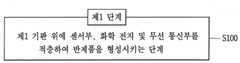
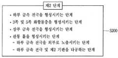
상기와 과제를 실현하기 위한 본 발명의 일 실시예와 관련된 플렉서블 센서 모듈의 제조 방법은, 제1기판 위에 센서부, 화학 전지 및 무선 통신부를 적층하여 반제품을 형성시키는 제1 단계; 및 태양 전지를 형성시키는 제2 단계를 포함하고,상기 제2 단계는, 상기 제1 기판과 마주보도록 배치되는 제2 기판 위에 하부 금속 전극을 형성시키는 단계; 상기 하부 금속 전극 위에 3족 및 5족 화합물층을 형성시키는 단계; 상기 3족 및 5족 화합물층 위에 상기 3족 및 5족 화합물층의 일부분이 외부로 노출되도록 상부 금속 전극을 형성시키는 단계; 및 적층된 상기 제2 기판, 상기 하부 금속 전극, 상기 3족 및 5족 화합물층 및 상기 상부 금속 전극을 관통하도록 관통 홀을 형성시키는 단계를 포함하며, 상기 반제품을 형성한 후 상기 태양 전지를 형성하여 상기 반제품 위에 상기 태양 전지를 결합시키거나, 상기 태양 전지를 형성한 후 상기 반제품을 형성하여 상기 반제품 위에 상기 태양 전지를 결합시키는 제3 단계를 포함할 수 있다.According to an embodiment of the present invention, there is provided a method of manufacturing a flexible sensor module, including: forming a sensor unit, a chemical battery, and a wireless communication unit on a first substrate to form a semi-finished product; And a second step of forming a solar cell, wherein the second step comprises: forming a lower metal electrode on a second substrate arranged to face the first substrate; Forming a Group 3 and
본 발명과 관련된 일 예에 따르면, 상기 관통 홀을 형성시키는 단계는, 상기 외부로 노출된 3족 및 5족 화합물층의 일부분을 제거하여 상기 하부 금속 전극을 외부로 노출시키는 단계; 및 상기 하부 금속 전극 및 상기 제2 기판을 타공하여 상기 센서부가 외부로 노출시키는 단계를 포함한다.According to an embodiment of the present invention, the step of forming the through holes may include exposing the lower metal electrode to the outside by removing a part of the Group III and
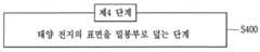
본 발명과 관련된 일 예에 따르면, 상기 반제품 위에 결합된 상기 태양 전지가 공기와 접촉되는 것을 방지하도록 상기 태양 전지의 표면을 밀봉부로 덮는 제4 단계를 더 포함한다.According to an embodiment of the present invention, the method further includes a fourth step of covering the surface of the solar cell with a sealing portion to prevent the solar cell coupled to the semi-finished product from coming into contact with air.
상기와 같은 구성의 본 발명에 의하면, 고효율의 태양 전지를 포함하여 센서 모듈의 작동을 위한 에너지를 공급할 수 있으며, 플렉서블한 특성을 가지므로 사용자는 곡면을 가지는 부위에도 부착하여 센서 모듈의 기능을 수행하도록 할 수 있다.According to the present invention having the above-described structure, it is possible to supply energy for the operation of the sensor module including the highly efficient solar cell, and since it has a flexible characteristic, the user can also attach to the curved surface area to perform the function of the sensor module .
또한, 센서 모듈의 제안된 구조를 통해 집적화되고, 비교적 크기가 작은 센서 모듈을 얻을 수 있게된다.Also, it is possible to obtain a sensor module which is integrated and relatively small in size through the proposed structure of the sensor module.
또한, 관통 홀을 구비하는 센서 모듈은 센서부를 외부로 노출시키는 구조를 통해 센서 모듈의 크기를 증가시키지 않으면서도 센서 모듈의 구현이 가능하게 된다.In addition, the sensor module including the through-hole allows the sensor module to be implemented without increasing the size of the sensor module through the structure for exposing the sensor unit to the outside.
또한, 상기와 같은 구성의 본 발명에 의하여, 센서 모듈을 제조할 수 있다.Further, according to the present invention having the above-described structure, the sensor module can be manufactured.
도 1은 태양 전지를 포함하는 플렉서블 센서 모듈의 사시도.
도 2는 도 1의 플렉서블 센서 모듈의 구조를 보여주는 측면도.
도 3은 태양 전지의 구조를 나타내는 측면도.
도 4는 도 3의 태양 전지를 밀봉부가 위에서 덮고 있는 모습을 나타내는 측면도.
도 5는 도 1의 플렉서블 센서 모듈과 다른 실시예를 나타내는 사시도.
도 6은 플렉서블 센서 모듈의 다른 실시예를 나타내는 측면도.
도 7은 도 6에 포함되는 태양 전지의 구조를 나타내는 측면도.
도 8의 (a) 및 (b)는 도 7에 포함되는 관통 홀에 의해 노출된 센서부와 상부 금속 전극을 보여주는 개념도.
도 9는 센서 모듈의 각 구성의 연결 관계를 보여주는 개념도.
도 10은 센서 모듈의 제조 방법을 나타내는 개념도.
도 11a 내지 도 11d는 센서 모듈의 제조 방법의 각 단계를 나타내는 순서도.1 is a perspective view of a flexible sensor module including a solar cell.
FIG. 2 is a side view showing the structure of the flexible sensor module of FIG. 1. FIG.
3 is a side view showing the structure of a solar cell.
Fig. 4 is a side view showing a state in which the sealing portion of the solar cell of Fig. 3 is covered.
FIG. 5 is a perspective view showing another embodiment of the flexible sensor module of FIG. 1;
6 is a side view showing another embodiment of the flexible sensor module;
7 is a side view showing the structure of a solar cell included in FIG. 6;
8 (a) and 8 (b) are conceptual views showing the sensor part and the upper metal electrode exposed by the through hole included in FIG. 7;
9 is a conceptual view showing a connection relationship of each configuration of the sensor module.
10 is a conceptual view showing a manufacturing method of a sensor module.
11A to 11D are flowcharts showing respective steps of a method of manufacturing a sensor module.
이하, 본 발명에 관련된 플렉서블 센서 모듈에 대하여 도면을 참조하여 보다 상세하게 설명한다.Hereinafter, a flexible sensor module according to the present invention will be described in detail with reference to the drawings.
본 명세서에서는 서로 다른 실시예라도 동일·유사한 구성에 대해서는 동일·유사한 참조번호를 부여하고, 그 설명은 처음 설명으로 갈음한다. 본 명세서에서 사용되는 단수의 표현은 문맥상 명백하게 다르게 뜻하지 않는 한 복수의 표현을 포함한다.In the present specification, the same or similar reference numerals are given to different embodiments in the same or similar configurations. As used herein, the singular forms "a", "an" and "the" include plural referents unless the context clearly dictates otherwise.
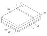
도 1은 플렉서블 센서 모듈(100)을 나타내는 사시도이고, 도 2는 플렉서블 센서 모듈(100)의 구조를 보여주는 측면도이다.FIG. 1 is a perspective view showing a
플렉서블 센서 모듈(100)은 센서부(110), 태양 전지(120), 무선 통신부(130) 및 화학 전지(140)를 포함하며, 도 1에서 보는 바와 같이, 이들 각 구성이 동일 기판 위에 수평형으로 적층되어 집적된 구조를 가지게 된다. 도 1에서 보는 바와 같이, 플렉서블 센서 모듈(100)은 제1 기판(111)이 하부에 위치되고, 그 위에 센서부(110), 태양 전지(120), 무선 통신부(130) 및 화학 전지(140)이 위치되는 구조를 가진다.The
플렉서블 센서 모듈(100)은 센서부(110)에 의해 외부 환경 정보를 수집하여 외부에 그 정보를 무선 통신부(130)를 통해 송신할 수 있는 것으로, 빛이 있는 환경에서는 태양 전지(120)를 통해 전원을 공급받아 그 기능을 수행하고, 빛이 없는 환경에서는 태양 전지(120)에 의해 생성되는 전원의 일부를 화학 전지(140)에 저장시킴으로써 정상적인 작동이 가능하게 된다.The
센서부(110), 태양 전지(120), 무선 통신부(130) 및 화학 전지(140)는 제1 기판(111) 위에 위치되는데, 각 구성의 특정 위치와 배열은 다양하게 이루어질 수 있다. 따라서 도 1에 나타난 구조 및 배열에 본 발명이 한정되는 것은 아니다. 또한, 각 구성은 동일 기판 위에 위치되는 것이라면, 서로 순서가 바뀌더라도 무관하다.The
본 발명에서의 기판은 각 구성을 지지하고, 기판에 형성되는 연결선을 통해 각 구성을 전기적으로 상호 연결하는 역할을 한다. 본 발명에 포함되는 기판은 유연한(flexible) 특성을 가지므로, 플렉서블 센서 모듈(100)은 굴곡이나 곡면을 가지는 벽면 혹은 장치에도 부착이 가능하게 된다.The substrate in the present invention supports each structure and electrically interconnects each structure through a connection line formed on the substrate. Since the substrate included in the present invention has a flexible characteristic, the
기판은 제1 기판(111), 제2 기판(121)을 포함한다. 제1 기판(111) 및 제2 기판(121)은 1mm 이하의 두께를 가지는 합성수지계열로 이루어져 구부러지거나 휘어질 수 있는 특성을 가진다. 다만, 제1 기판(111)과 제2 기판(121)은 본 재료에만 한정되는 것은 아니다.The substrate includes a
도 2는 플렉서블 센서 모듈(100)의 각 구성을 보여준다. 플렉서블 센서 모듈(100)에 포함되는 각 구성과 이들 각 구성의 상호 작용에 대하여 살펴본다.Fig. 2 shows each configuration of the
센서부(110)는 제1 기판(111) 위에 납이나 합성 수지 등의 다양한 수단을 통해서 고정될 수 있다. 센서부(110)는 외부의 환경 정보를 측정하는 역할을 하는 것으로, 센서부(110)는 외부로 노출되어 외부의 온도, 습도, 가스 농도 및 조도 중 적어도 어느 하나를 측정하는 역할을 한다. 이와 같은 역할을 하기 위하여, 센서부(110)는 온도 센서, 습도 센서, 가스 농도 측정 센서 및 조도 센서 중 적어도 어느 하나를 포함하거나, 이들 각 센서의 역할을 하는 복합 센서 혹은 서로 다른 복수 개의 센서로 구성될 수도 있다.The
센서부(110)는 사용 목적에 따라 가스 농도, 온도, 습도, 조도 등을 측정할 수 있으며, 복수개의 센서가 결합되어 다양한 기능을 수행할 수 있다. 센서부(110)의 구조와 그 형상도 특별한 제한이 없다. 다만, 센서부(110)는 일반적으로 모듈의 형태를 가질 것이므로, 센서부(110) 역시 유연한 특성을 가지는 기판을 구성으로 포함하는 것이 바람직 할 것이다.The
도 2에서 보듯이, 센서부(110)는 외부의 환경 정보를 측정하는 기능을 수행해야 하므로, 외부에 노출되도록 위치된다. As shown in FIG. 2, the
무선 통신부(130)는 제1 기판(111) 위의 일 측에 위치될 수 있고, 제1 기판(111) 위의 일 측에 위치된 센서부(110)와 나란하게 위치될 수 있다. 무선 통신부(130)는 센서부(110)로부터 측정된 정보를 외부 서버로 전송하는 역할을 하는 것으로, 약 1.56MHz 내지 2.54GHz의 비교적 넓은 범위를 주파수로 선택하여 무선 통신 기능을 수행할 수 있다. 센서부(110)에 의해 측정된 온도, 가스 농도, 조도, 습도 등의 정보는 무선 통신부(130)를 통해 외부 서버로 전송될 수 있고, 사용자는 전송된 정보를 컴퓨터, 스마트폰, 노트북 등의 다양한 장치를 통해 수신하여 확인할 수 있을 것이다.The
무선 통신부(130)는 유연한 특성을 가지도록, 1mm 이내의 두께를 구성되는 것이 바람직할 것이다. 무선 통신부(130)는 외부로 노출되지 않아도 되므로 무선 통신부(130)가 배치되는 위치에는 제한이 없다. 도 2에서 보는 바와 같이, 무선 통신부(130)는 제1 기판(111) 위에 일 측에 납이나, 합성 수지 등을 이용하여 고정되게 된다. 즉, 무선 통신부(130)는 센서부(110)와 동일 평면 위에 위치하게 된다.The
화학 전지(140)는 화학 에너지를 전기 에너지로 변환하여 각 구성에 전원을 공급하는 역할을 하는 것으로, 아연(Zn), 리튬(Li) 등을 포함하는 2차 전지로 구성될 수 있다. 화학 전지(140)는 유연한 특성을 가질 수 있도록, 1mm 이내의 두께로 이루어지는 것이 바람직할 것이다. 태양 전지(120)가 전원을 생성할 수 없는 환경일 때, 화학 전지(140)는 센서부(110) 및 무선 통신부(130)가 작동될 수 있도록 저장된 전력을 센서부(100) 및 무선 통신부(130)에 공급하는 역할을 하게 된다.The
화학 전지(140)는 제1 기판(111) 위의 일 측에 위치되어, 무선 통신부(130) 및 센서부(110)와 동일 평면에 위치될 수 있다. 화학 전지(140)는 태양 전지(120)로부터 전원을 공급받음으로써 충전되고, 충전된 전원은 태양 전지(120)가 빛을 흡수하지 못하여, 전원을 생성하지 못할 때, 센서부(110) 및 무선 통신부(130)의 동작을 위한 전원을 공급하는 역할을 한다.The
빛이 없는 환경에서 태양 전지(120)의 작동이 어려운 경우, 화학 전지(140)는 충전된 전원을 센서부(110) 및 무선 통신부(130)에 공급하여 이들을 작동시키게 된다. 화학 전지(140)가 배치되는 위치에는 특별한 제한이 없으며, 도 2에서는 화학 전지(140)를 센서부(100), 무선 통신부(130) 및 태양 전지(120)와 동일 평면 위에 위치되도록 하였다.When the
도 1과 도 2에서 보듯이, 제1 기판(111) 위에 위치되는 센서부(110), 무선 통신부(130) 및 화학 전지(140)는 각 구성 사이에 접착재(10)가 개재됨으로써 제1 기판(111) 위의 특정 위치에 고정될 수 있게 된다.1 and 2, the
도 3과 도 4는 태양 전지(120)의 구조를 나타내는 도면이다.FIGS. 3 and 4 are views showing the structure of the
태양 전지(120)는 태양 에너지를 전기 에너지로 변환하는 역할을 하는 것으로, 태양으로부터 생성된 빛에너지를 전기 에너지로 바꾸는 역할을 한다. 도 1과 도 2에서 보듯이, 태양 전지(120)는 제1 기판(111) 위의 일 측에 위치되고, 센서부(110), 화학 전지(140) 및 무선 통신부(130)와 동일 평면 상에 위치하게 된다.The
태양 전지(120)는 제2 기판(121), 화합물층(123), 금속 전극(125)을 포함한다.The
태양 전지(120)는 제1 기판(111) 위에 위치되므로, 제2 기판(121)은 제1 기판(111)과 마주보게 된다. 제2 기판(121)은 하부에서 금속 전극(125) 및 화합물층(123)을 지지하는 역할을 한다. 제2 기판(121)은 제2 기판(121)에 형성되는 구리 전극을 통해 제1 기판(111)과 연결되고, 센서부(110), 화학 전지(140) 및 무선 통신부(130)와 연결된다. 제2 기판(121)은 상기 기재한 기판에 관한 내용과 동일하다.Since the
태양 전지(120)의 화합물층(123)에 빛이 들어오게 되면, 빛에너지에 의하여 전자와 정공이 생기는데, p형 반도체의 다수의 캐리어는 정공이고 소수의 캐리어는 전자를 형성한다. 빛에 의해 형성된 전자와 정공 및 이에 의해 형성된 밀도차에 의해 전자와 정공은 주변으로 확산되고 전위차가 p-n 접합부에 도달되면, 강한 전기장에 의하여 전자와 정공은 분리되게 된다. p형 반도체에서 확산된 전자는 n형 반도체 쪽으로, n형 반도체에서 확산된 정공은 p형 반도체 쪽으로 이동하게 되고, 전류가 흐르는 원리에 의해 전원이 생산될 수 있게 된다. 본 발명에서는 태양 전지(120)의 상부 금속 전극(125a) 및 하부 금속 전극(125b)이 각각 n층 및 p층 역할을 하게 된다.When light enters the
화합물층(123)은 제2 기판(121) 위에 위치되고, 빛을 받아 전자와 정공을 분리시킴으로써 전원을 발생시키는 역할을 하게 된다. 화합물층(123)은 3족 및 5족 화합물이 적층되는 방식으로 이루어진다. 여기서 3족 및 5족 화합물이란, 주기율표상의 3족 및 5족 원소의 결합으로 형성되는 것으로 3족 원소로는 갈륨(Ga), 5족 원소로는 비소(As)가 사용될 수 있다. 화합물층(123)은 유연한 특성을 가지도록 약 3㎛ 이하의 단위 박막으로 이루어질 수 있을 것이다.The
갈륨(Ga) 및 비소(As)를 포함하여 태양 전지(120)를 구성하게 되면, 기존의 Si계 태양 전지(120)에 비해 높은 발전량을 제공할 수 있고, 400 lux의 조도가 낮은 환경에서도 높은 발전량의 제공할 수 있게 된다.The
갈륨(Ga) 및 비소(As)를 포함하는 태양 전지(120)는 3㎛ 이내의 얇은 두께에서도 높은 발전 효율을 가질 수 있고, 휘어짐(bending)이 가능하여 플렉서블한 특성을 가진다. 이에 형성되는 센서 모듈은 얇고, 컴팩트한 외형 및 가벼운 특성을 가질 수 있다.The
도 3과 도 4를 보면, 금속 전극(125)은 화합물층(123)의 표면에 형성되는 것으로, 금속 전극(125)은 상부 금속 전극(125a) 및 하부 금속 전극(125b)을 포함한다.3 and 4, the
상부 금속 전극(125a)은 화합물층(123) 위에 위치되고, 상부 금속 전극(125a)은 핑거(125a', 도 8 참조) 및 버스바(125a", 도 8 참조)를 포함한다. 하부 금속 전극(125b)은 제2기판과 화합물층(123)의 사이에 위치되며 화합물층(123)을 기준으로 상부 금속 전극(125a)과 반대쪽에 위치된다.The
상부 금속 전극(125a) 및 하부 금속 전극(125b)은 빛에 의해 형성되는 전하를 수집하기 위해 화합물층(123)의 전, 후면에서 전자와 양공을 형성시키는 전극의 역할을 하게 된다. 본 발명에서 상부 금속 전극(125a)은 n층을, 하부 금속 전극(125b)은 p층을 형성하게 된다.The
상부 금속 전극(125a) 및 하부 금속 전극(125b)은 금속 페이스트(paste)를 이용하여 형성되는데, 상부 금속 전극(125a)은 알루미늄(Al) 페이스트(paste)가 사용되는 것이 일반적이고, 하부 금속 전극(125b)은 은(Ag) 페이스트(paste)가 사용되는 것이 일반적이다.The
태양 전지(120)에 태양광이 조사되면, 화합물층(123), 상부 금속 전극(125a) 및 하부 금속 전극(125b) 간의 상호 작용에 의해 광전효과가 발생하여 기전력이 생기게 되며, 발생된 전원은 저장되거나 전원이 필요한 장치에 연결됨으로써 이용되게 된다. 여기서 광전 효과란, 빛을 흡수하여 전하를 생성하는 것을 의미한다.When the
태양 전지(120)는 도 4에서와 같이, 태양 전지(120)가 외부로 노출되는 것을 제한하도록, 태양 전지(120)의 표면을 덮는 밀봉부(150)를 더 포함할 수 있다. 밀봉부(150)는 태양 전지(120)의 상부에 위치된다. 밀봉부(150)는 태양 전지(120)가 외부로 노출되어 수분이 침투되거나 오염되는 것을 막기 위해 투명한 합성수지로 이루어질 수 있다. 예를 들어, 합성수지는 PVC 같은 물질로 이루어질 수 있다.The
도 5는 본 발명에 따르는 플렉서블 센서 모듈(100)의 다른 실시예이다.5 is another embodiment of the
플렉서블 센서 모듈(100)은 센서부(110), 태양 전지(120), 무선 통신부(130) 및 화학 전지(140)를 포함하며, 이들 각 구성이 기판 위에 적층되어 형성되는 구조를 가진다. 다만, 도 1의 플렉서블 센서 모듈(100)의 구조와는 다르게, 각 구성이 수평형으로 나란하게 적층되는 것이 아닌, 일부 구성 위에 다른 구성이 적층되는 적층형으로 이루어 질 수 있다.The
도 5에서 보는 바와 같이, 플렉서블 센서 모듈(100)은 하부에 화학 전지(140) 및 무선 통신부(130)가 위치되고, 화학 전지(140) 및 무선 통신부(130) 위에는 센서부(110) 및 태양 전지(120)가 위치될 수 있다.5, the
도 5는 태양 전지(120) 아래에 무선 통신부(130)가 위치되고, 센서부(110)의 아래에 화학 전지(140)가 위치되는 구성에 대해 나타내고 있으나, 태양 전지(120)와 센서부(110)의 위치는 서로 바뀌어도 무방하다. 다만, 태양 전지(120)는 외부로부터 빛을 흡수해 전원을 생성하여야 하고, 센서부(110)는 외부로 노출되어 외부의 환경 정보를 측정해야 하므로, 태양 전지(120) 및 센서부(110)는 외부에 노출되도록 위치되어야 할 것이다. 화학 전지(140) 및 무선 통신부(130)는 외부에 노출되지 않더라도 기능 수행에 문제 없으므로, 외부에 노출되도록 위치되지 않아도 될 것이다. 즉, 태양 전지(120)는 외부에 노출되어 빛을 흡수하도록, 무선 통신부(130) 및 화학 전지(140) 중 적어도 하나 위에 위치될 수 있고, 센서부(110)는 외부의 환경 정보 측정을 위하여, 무선 통신부(130) 및 화학 전지(140) 중 적어도 하나 위에 위치될 수 있다.5 shows a configuration in which the
도 6은 플렉서블 센서 모듈(100)의 다른 실시예를 나타내는 것으로, 관통홀(127)이 형성되는 플렉서블 센서 모듈(100)의 모습을 나타낸다. 도 7은 관통홀(127)을 구비하는 태양 전지(120)의 구조를 보여주는 도면이다.6 shows another embodiment of the
플렉서블 센서 모듈(100)은 센서부(110), 태양 전지(120), 무선 통신부(130) 및 화학 전지(140)를 포함하며, 이들 각 구성이 기판 위에 적층되어 형성되는 구조를 가진다. 플렉서블 센서 모듈(100)은 제1 기판(111) 위에 센서부(110), 무선 통신부(130) 및 화학 전지(140)가 나란하게 배치될 수 있고, 그 위에 태양 전지(120)가 위치하게 된다. 다만, 센서부(110), 무선 통신부(130) 및 화학 전지(140)의 위치는 도 6에 나타난 구조에만 한정되는 것은 아니고, 서로 위치가 바뀌더라도 무방하다.The
플렉서블 센서 모듈(100)에 포함되는 기판은 유연한(flexible) 특성을 가지고, 이러한 기판을 포함하여 구성되므로 상기에서 설명한 바와 같이, 굴곡이나 곡면을 가지는 벽면 혹은 장치에 부착될 수 있다.The substrate included in the
센서부(110)는 제1 기판(111) 위에 위치된다. 센서부(110)는 태양 전지(120)에 형성되어 있는 관통 홀(127)을 통해 외부로 노출되어 외부의 온도, 습도, 가스 농도 및 조도 중 적어도 어느 하나를 측정하게 된다. 센서부(110)에 관한 설명은 상기 기재한 바와 같다.The
무선 통신부(130)는 제1 기판(111) 위에 위치되어 센서부(110)와 동일 평면 위에 위치되거나 센서부(110)보다 아래쪽에 위치될 수 있다. 화학 전지(140)는 센서부(110)와 나란하게 배치되거나 센서부(110)의 아래쪽에 배치될 수 있다. 도 6에서 보듯이, 제1 기판(111) 위에는 센서부(110), 무선 통신부(130) 및 화학 전지(140)가 나란하게 배치되는 구조를 가지는데, 이들 각 구성은 구성 사이에 개재되는 접착재(10)에 의해 제1 기판(111) 위의 특정 위치에 고정될 수 있게 된다.The
도 6과 도 7에서 보듯이, 태양 전지(120)는 센서부(110)보다 위쪽에 위치되고, 태양 전지(120)의 관통 홀(127)에 의해 센서부(110)를 외부로 노출시키는 구조를 가진다. 태양 전지(120)는 제2 기판(121), 화합물층(123), 금속 전극(125) 및 이들을 관통하는 관통 홀(127)을 포함한다.6 and 7, the
제2 기판(121)은 제1 기판(111)과 마주보도록 배치되고, 하부에서 금속 전극(125) 및 화합물층(123)을 지지하는 역할을 한다. 제2 기판(121)은 제2 기판(121)에 배치되는 구리 전극을 통해 제2 기판(121)의 아래에 위치되는 센서부(110), 화학 전지(140) 및 무선 통신부(130)를 상호간에 연결하는 역할을 하게 된다. 화합물층(123)은 제2 기판(121) 위에 위치되는 것으로, 3족 및 5족 화합물이 적층되는 방식으로 이루어진다. 3족 원소로는 갈륨(Ga), 5족 원소로는 비소(As)가 사용될 수 있다. 금속 전극(125)은 화합물층(123)의 표면에 형성되는 것으로, 금속 전극(125)은 상부 금속 전극(125a) 및 하부 금속 전극(125b)을 포함한다.The
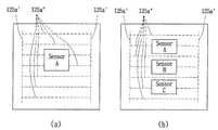
도 8 (a)는 관통 홀(127)에 의해 외부로 노출된 센서 A의 주위로 상부 금속 전극(125a)이 형성되는 모습을 나타내고, 도 8의 (b)는 관통 홀(127)에 의해 외부로 노출된 센서 A, B, C 및 센서 A, B, C의 주위로 상부 금속 전극(125a)이 형성되는 모습을 나타낸다.8A shows a state in which the
상부 금속 전극(125a)은 화합물층(123) 위에 위치되고, 상부 금속 전극(125a)은 핑거(125a') 및 버스바(125a")를 포함한다. 가로 방향으로 연장되는 복수 개의 점선은 상부 금속 전극(125a)의 핑거(125a')를 나타내고, 세로 방향으로 연장되고 핑거(125a')의 양단에 위치되는 점선은 버스바(125a")를 나타낸다. 핑거(125a')는 화합물층(123)과 넓은 면적에서 맞닿아 화합물층(123)에서 형성되는 전류를 전달받는 역할을 한다. 버스바(125a")는 핑거(125a')와 연결되어 핑거(125a')에 의해 전류를 전달받아 화합물층(123)에서 형성되는 전류를 수집하는 역할을 한다.The
하부 금속 전극(125b)은 제2기판과 화합물층(123)의 사이에 위치되며 화합물층(123)을 기준으로 상부 금속 전극(125a)과 반대쪽에 위치된다.The
상부 금속 전극(125a) 및 하부 금속 전극(125b)은 빛에 의해 형성되는 전하를 수집하기 위해 화합물층(123)의 전, 후면에서 전자와 양공을 형성시키는 전극의 역할을 하게 된다. 본 발명에서 상부 금속 전극(125a)은 n층을, 하부 금속 전극(125b)은 p층을 형성하게 된다.The
상부 금속 전극(125a) 및 하부 금속 전극(125b)은 금속 페이스트(paste)를 이용하여 형성하게 되는데, 상부 금속 전극(125a)은 알루미늄(Al) 페이스트(paste)가 사용되는 것이 일반적이고, 하부 금속 전극(125b)은 은(Ag) 페이스트(paste)가 사용되는 것이 일반적이다.The
태양 전지(120)에 태양광이 조사되면, 화합물층(123), 상부 금속 전극(125a) 및 하부 금속 전극(125b) 간의 상호 작용에 의해 광전효과가 발생하여 기전력이 생기게되며, 발생된 전원은 저장되거나 전원이 필요한 장치에 연결됨으로써 이용되게 된다.When the
도 7에서 보는 바와 같이, 태양 전지(120)는 관통 홀(127)을 중심으로 양쪽에서 제2 기판(121), 하부 금속 전극(125b), 화합물층(123) 및 상부 금속 전극(125a)의 순서로 적층되어 서로 마주보도록 배치되는 구조를 가진다. 관통 홀(127)은 센서부(110)를 외부로 노출시키도록 태양 전지(120)의 상부 및 하부를 관통하는 역할을 하게 된다. 센서부(110)를 외부로 노출시킬 수 있다면 관통 홀(127)의 형상에는 특별한 제한이 없다.7, the
태양 전지(120)에 형성되는 관통 홀(127)에 의해 센서부(110)는 외부로 노출가능하고, 센서부(110)는 외부의 환경 정보를 측정할 수 있다. 관통 홀(127)을 통해 센서부(110)를 외부로 노출시키는 것은 태양 전지(120)의 좌측 혹은 우측에 별도로 위치시키는 것에 비해 모듈의 배치 및 공간 활용 측면에서 이점이 있다. 또한, 하나의 기판으로 형성할 때, 기판에 존재하게 되는 불필요한 공간(dead area)을 최소화할 수 있게 된다.The
태양 전지(120)에서 관통 홀(127)이 형성되는 위치에는 특별한 제한이 없으나, 관통 홀(127)을 중심으로 태양 전지(120)의 금속 전극(125)이 대칭성을 가지도록 구성되어야 높은 발전 효율을 가지므로, 태양 전지(120)의 중앙부에 센서 모듈이 노출되도록 관통 홀(127)이 형성되는 것이 바람직하다.The position where the through
태양 전지(120), 센서부(110), 무선 통신부(130) 및 화학 전지(140)는 제1 기판(111) 및 제2 기판(121)에 형성되는 연결선에 의해 각 구성들끼리 서로 연결되고, 화학 전지(140) 및 태양 전지(120)는 각 구성에 전원을 공급할 수 있게 된다. 연결선은 통상 금속으로 이루어지고, 그 중 구리로 이루어지는게 일반적일 것이다.The
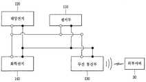
도 9는 태양 전지(120), 센서부(110), 무선 통신부(130) 및 화학 전지(140)의 상호 연결 관계에 대해서 나타낸다. 도 9를 보면, 태양 전지(120)는 화학 전지(140)와 연결되어 태양 전지(120)에 의해서 발생된 전력을 화학 전지(140)에 저장시킬 수 있도록 구성하였고, 태양 전지(120)와 화학 전지(140)는 센서부(110) 및 무선 통신부(130)와 각각 연결된다. 센서부(110) 및 무선 통신부(130)는 외부로부터 빛을 받을 수 있는 환경에서는 태양 전지(120)에 의해 전원을 공급받게 되고, 빛이 없는 환경에서는 태양 전지(120)에 의해 충전된 화학 전지(140)로부터 전원을 공급받게 된다. 도 9에서와 같이, 각 구성 간의 연결선은 하나의 선의 연결이 끊어지더라도 연결이 유지될 수 있도록 복수개로 이루어질 것이다.9 shows the interconnections between the
센서 모듈(100)은 제1 기판(111) 위에 위치되는 센서부(110), 화학 전지(140)와 나란하게 위치되면서 센서부(110)에 의해 측정된 신호를 증폭시키는 신호 증폭부(미도시)가 더 포함될 수 있다. 신호 증폭부(미도시)의 구조 및 형상에는 특별한 제한이 없다.The
플렉서블 센서 모듈(100)은 태양 전지(120)가 외부로 노출되는 것을 제한하도록 태양 전지(120)의 표면을 덮는 밀봉부(150)를 더 포함할 수 있다. 밀봉부(150)에 관한 설명은 상기 기재한 바와 같다.The
센서부(110)는 외부로 노출되어 외부의 환경 정보를 측정하여야 하므로 센서부(110)는 밀봉부(150)에 의해 노출이 제한되지 않도록 구성되어야 하므로, 도 6과 도 7에서 보는 바와 같이, 밀봉부(150)는 센서부(110)를 외부로 노출시키면서, 태양 전지(120)를 이루는 각 구성을 덮게 된다. 이에Since the
도 8의 (a)와 (b)에서 보듯이, 태양 전지(120)에 형성된 하나의 관통 홀(127)에 의해 노출되는 센서부에 의해서 외부의 환경 정보를 측정하는 역할을 하게 된다.As shown in FIGS. 8A and 8B, the sensor unit exposed by one through
센서 모듈(100)은 태양 전지(120)에 형성된 관통 홀(127)을 통해 센서부(110)가 외부로 노출되는 구성을 가지고 있으므로, 구성을 최적화 할 수 있고, 효율화를 도모할 수 있는 장점이 있다. 또한, 센서 모듈(100)은 유연한 특성으로 인해 휘어질 수 있고, 두께가 얇으므로 곡면에도 자유롭게 부착될 수 있다. 센서부(110)는 부착되는 센서의 종류에 따라 가스 농도, 조도, 온도, 습도 등을 측정할 수 있으며, 무선 통신부(130)를 통해 정보를 송신하여 수신 기능이 있는 스마트폰, 노트북, 태블릿PC, 컴퓨터에 정보를 제공할 수 있다.Since the
이상으로 센서 모듈(100)의 구조 및 각 구성에 따른 작동에 대해 살펴보았고, 이하에서는 도 10과 도 11A 내지 도 11D를 참조하여 관통 홀(127)을 구비하는 센서 모듈(100)을 제조하는 방법에 대해서 살펴본다.Hereinafter, the structure of the
도 10은 관통 홀(127)을 구비하는 센서 모듈(100)의 제조하는 방법을 나타내는 도면이다. 다만, 이는 관통 홀(127)을 구비하지 않는, 도 2와 같은 센서 모듈(100)을 제조하는데 이용가능할 것이다.10 is a view showing a method of manufacturing the
센서 모듈(100)은 제1 단계, 제2 단계, 제3 단계 및 제4 단계를 거쳐 제조될 수 있다.The
도 10의 상단 좌측 및 도 11A를 보면, 제1 단계는 제1 기판(111) 위에 센서부(110), 화학 전지(140) 및 무선 통신부(130)를 적층하여 반제품을 형성시키는 단계이다. 이때, 센서부(110), 화학 전지(140) 및 무선 통신부(130)는 도 6의 센서 모듈(100)의 구조에서 살펴보았듯이, 제1 기판(111) 위의 동일 평면상에 위치되도록, 서로 나란하게 배치되고 이들 사이에 접착재(10)가 개재되어 고정되게 된다.10, the first step is a step of laminating the
도 10의 우측 상단 및 도 11B를 보면, 제2 단계는 태양 전지(120)를 형성시키는 단계이다. 제2 단계는 제2 기판(121) 위에 하부 금속 전극(125b)을 형성시키는 단계, 하부 금속 전극(125b) 위에 3족 및 5족 화합물층(123)을 형성시키는 단계, 3족 및 5족 화합물층(123) 위에 상부 금속 전극(125a)을 형성시키는 단계, 적층된 제2 기판(121), 하부 금속 전극(125b), 3족 및 5족 화합물층(123) 및 상부 금속 전극(125a)을 관통하도록 관통 홀(127)을 형성시키는 단계로 구성된다.10 and 11B, the second step is the step of forming the
여기서 관통 홀(127)을 형성시키는 단계는, 도 10에서 보듯이, 외부로 노출된 3족 및 5족 화합물층(123)의 일부분을 화학적인 방법으로 제거하고 상기 하부 금속 전극(125b)을 외부로 노출시키는 단계와 하부 금속 전극(125b) 및 제2 기판(121)을 타공하여 센서부(110)가 외부로 노출시키는 단계로 구성된다. 관통 홀(127)을 형성시켜 센서부(110)를 외부로 노출시키는 것은 노출된 하부 금속 전극(125b) 및 제2 기판(121)을 레이저, 커터, 펀칭을 이용하여 타공함으로써 형성시킬 수 있다.As shown in FIG. 10, the step of forming the through
다시 말하면, 태양 전지(120)에 관통 홀(127)을 형성시키는 방법은 상부 금속 전극(125a) 사이로 노출된 화합물층(123)을 화학적인 방법으로 제거하고, 노출된 하부 금속 전극(125b) 및 제2 기판(121)을 레이저, 커터, 펀칭 등의 방법을 이용하여 타공함으로써 형성할 수 있게 된다.In other words, in the method of forming the through
도 10 및 도 11C를 보면, 제3 단계는 상기 반제품을 형성한 후 상기 태양 전지(120)를 형성하여 상기 반제품 위에 상기 태양 전지(120)를 결합시키거나, 상기 태양 전지(120)를 형성한 후 상기 반제품을 형성하여 상기 반제품 위에 상기 태양 전지(120)를 결합시키는 단계를 의미한다.10 and 11C, in the third step, after the semi-finished product is formed, the
제3 단계는 상기 반제품과 상기 태양 전지(120)를 결합시키는 단계로서, 제1 단계에 의해 형성되는 반제품 위에 제2 단계에 의해 형성되는 상기 태양 전지(120)를 결합시키거나, 제2 단계에 의해 태양 전지(120)를 형성시킨 후 제1 단계에 의해 반제품을 형성시킨 후 이들을 결합시키는 단계를 의미한다. 다만, 제3 단계는 제1 단계와 제2 단계를 병행하여 형성시킨 후에 제1 단계에 의해 형성되는 반제품과 제2 단계에 의해 형성되는 태양 전지(120)를 결합시키는 단계로 이루어질 수도 있다.The third step is a step of combining the semi-finished product and the
도 10 및 도 11D를 보면, 제4 단계는 상기 반제품 위에 결합된 상기 태양 전지(120)가 공기와 접촉되는 것을 방지하도록 상기 태양 전지(120)의 표면을 밀봉부(150)로 덮는 단계를 의미한다. 여기서 밀봉부(150)는 상기 센서 모듈(100)의 구조에서 설명한 바와 동일한 특성을 가진다.10 and 11D, the fourth step is to cover the surface of the
도 10은 제1 단계, 제2 단계, 제3 단계 및 제4 단계를 거치면서 플렉서블 센서 모듈(100)을 제조하는 방법 전체를 개략적으로 나타내는 것으로, 이와 같은 방법으로 플렉서블 센서 모듈(100)을 형성할 수 있게 된다.10 schematically shows a whole method of manufacturing the
이상에서 설명된 센서 모듈 및 이의 제조 방법은 상기 설명된 실시예들의 구성과 방법에 한정되는 것이 아니라, 상기 실시예들의 다양한 변형이 이루어질 수 있도록, 각 실시예들의 전부 또는 일부가 선택적으로 조합될 수 있다.The sensor module and the method of manufacturing the sensor module described above are not limited to the configuration and the method of the embodiments described above, but all or some of the embodiments may be selectively combined so that various modifications of the embodiments can be made. have.
100: 플렉서블 센서 모듈 110: 센서부
120: 태양 전지 127: 관통 홀
130: 무선 통신부 140: 화학 전지
150: 밀봉부100: Flexible sensor module 110: Sensor part
120: Solar cell 127: Through hole
130: wireless communication unit 140: chemical battery
150:
Claims (16)
Translated fromKorean상기 센서부와 나란하게 배치되고, 빛을 받아 전원을 생성하는 태양 전지;
상기 제1 기판 위의 일 측에 위치되고, 상기 센서부로부터 측정된 정보를 외부 서버로 전송하는 무선 통신부; 및
상기 제1 기판 위의 다른 일 측에 위치되고, 상기 태양 전지로부터 전원을 공급받아 충전되며, 충전된 전원을 상기 센서부 및 상기 무선 통신부에 공급하는 화학 전지를 포함하고,
상기 태양 전지는,
제2 기판 위에 위치되고, 빛을 받아 상기 센서부에 공급되는 전원을 생성하는 화합물층; 및
상기 화합물층의 표면에 형성되는 금속 전극을 포함하는 것을 특징으로 하는 플렉서블 센서 모듈.A sensor unit positioned on the first substrate so as to be exposed to the outside for measurement of external environmental information;
A solar cell disposed in parallel to the sensor unit and receiving light to generate power;
A wireless communication unit located on one side of the first substrate and transmitting information measured by the sensor unit to an external server; And
And a chemical battery which is located on the other side of the first substrate and is supplied with power from the solar cell and supplies the charged power to the sensor unit and the wireless communication unit,
In the solar cell,
A compound layer which is positioned on the second substrate and generates power to be supplied to the sensor unit by receiving light; And
And a metal electrode formed on a surface of the compound layer.
상기 센서부, 태양 전지, 무선 통신부 및 화학 전지는,
상기 제1 기판 위의 서로 다른 위치에 각각 배치되는 것을 특징으로 하는 플렉서블 센서 모듈.The method according to claim 1,
The sensor unit, the solar cell, the wireless communication unit,
Wherein the first and second substrates are disposed at different positions on the first substrate.
상기 태양 전지는,
외부에 노출되어 빛을 흡수하도록, 상기 무선 통신부 및 상기 화학 전지 중 적어도 하나 위에 위치되는 것을 특징으로 하는 플렉서블 센서 모듈.The method according to claim 1,
In the solar cell,
And is located on at least one of the wireless communication unit and the chemical battery so as to be exposed to the outside to absorb light.
상기 금속 전극은 상기 태양 전지, 상기 센서부, 상기 무선 통신부 및 상기 화학 전지를 각각 연결하고,
상기 금속 전극은,
상기 화합물층 위에 형성되는 상부 금속 전극; 및
상기 제2 기판과 상기 화합물층의 사이에 위치되고, 상기 화합물층을 기준으로 상기 상부 금속 전극과 반대쪽에 위치되는 하부 금속 전극을 포함하는 것을 특징으로 하는 플렉서블 센서 모듈.The method according to claim 1,
Wherein the metal electrode connects the solar cell, the sensor unit, the wireless communication unit, and the chemical battery,
The metal electrode
An upper metal electrode formed on the compound layer; And
And a lower metal electrode located between the second substrate and the compound layer and positioned on the opposite side of the upper metal electrode with respect to the compound layer.
상기 센서부는, 외부로 노출되어 외부의 온도, 습도, 가스 농도 및 조도 중 적어도 어느 하나를 측정하는 것을 특징으로 하는 플렉서블 센서 모듈.The method according to claim 1,
Wherein the sensor unit is exposed to the outside and measures at least one of external temperature, humidity, gas concentration, and illuminance.
상기 화합물층은, 3족 및 5족 화합물의 적층으로 형성되는 것을 특징으로 하는 플렉서블 센서 모듈.6. The method of claim 5,
Wherein the compound layer is formed of a laminate of Group 3 and Group 5 compounds.
상기 3족 및 5족 화합물은, 갈륨(Ga) 및 비소(As)로 이루어지는 것을 특징으로 하는 플렉서블 센서 모듈.The method according to claim 6,
Wherein the Group 3 and Group 5 compounds are composed of gallium (Ga) and arsenic (As).
상기 센서부 위에 위치되는 태양 전지;
상기 제1 기판 위에서 상기 태양 전지와 나란하게 배치되고, 상기 센서부로부터 측정된 정보를 외부 서버로 전송하는 무선 통신부; 및
상기 제1 기판 위에서 상기 무선 통신부와 나란하도록 배치되고, 상기 태양 전지로부터 전원을 공급받아 충전되며, 충전된 전원을 상기 센서부 및 상기 무선 통신부에 공급하는 화학 전지를 포함하고,
상기 태양 전지는,
상기 제1 기판과 마주보도록 배치되는 제2 기판;
상기 제2 기판 위에 위치되고, 빛을 받아 상기 센서부에 공급되는 전원을 생성하는 화합물층;
상기 화합물층의 표면에 형성되는 금속 전극; 및
상기 센서부의 외부 노출을 위해 상기 태양 전지의 상하부를 관통하도록 형성되는 적어도 하나 이상의 관통 홀을 포함하는 것을 특징으로 하는 플렉서블 센서 모듈.A sensor unit positioned on the first substrate and measuring external environment information;
A solar cell positioned above the sensor unit;
A wireless communication unit arranged on the first substrate in parallel with the solar cell and transmitting the measured information from the sensor unit to an external server; And
And a chemical battery that is arranged on the first substrate so as to be in parallel with the wireless communication unit and is supplied with power from the solar cell and supplies the charged power to the sensor unit and the wireless communication unit,
In the solar cell,
A second substrate disposed to face the first substrate;
A compound layer located on the second substrate and generating power to be supplied to the sensor unit by receiving light;
A metal electrode formed on a surface of the compound layer; And
And at least one through hole formed to pass through upper and lower portions of the solar cell for external exposure of the sensor unit.
상기 금속 전극은 상기 태양 전지, 상기 센서부, 상기 무선 통신부 및 상기 화학 전지를 서로 연결하고,
상기 금속 전극은,
상기 화합물층 위에 형성되는 상부 금속 전극; 및
상기 제2 기판과 상기 화합물층의 사이에 위치되고, 상기 화합물층을 기준으로 상기 상부 금속 전극과 반대쪽에 위치되는 하부 금속 전극을 포함하는 것을 특징으로 하는 플렉서블 센서 모듈.9. The method of claim 8,
Wherein the metal electrode connects the solar cell, the sensor unit, the wireless communication unit, and the chemical battery to each other,
The metal electrode
An upper metal electrode formed on the compound layer; And
And a lower metal electrode located between the second substrate and the compound layer and positioned on the opposite side of the upper metal electrode with respect to the compound layer.
상기 태양 전지는, 상기 관통 홀을 중심으로 양쪽에서 상기 제2 기판, 상기 하부 금속 전극, 상기 화합물층 및 상기 상부 금속 전극의 순서로 적층되어 서로 마주보도록 배치되는 것을 특징으로 하는 플렉서블 센서 모듈.9. The method of claim 8,
Wherein the solar cell is stacked in such a manner that the second substrate, the lower metal electrode, the compound layer, and the upper metal electrode are stacked in the order of facing each other with respect to the through hole and facing each other.
상기 센서부는, 상기 각 관통 홀을 통해 외부로 노출되어 외부의 온도, 습도, 가스 농도 및 조도 중 적어도 어느 하나를 측정하는 것을 특징으로 하는 플렉서블 센서 모듈.9. The method of claim 8,
Wherein the sensor unit is exposed to the outside through the through holes to measure at least one of temperature, humidity, gas concentration and illuminance of the outside.
상기 태양 전지가 외부로 노출되는 것을 제한하도록 상기 태양 전지의 표면을 덮는 밀봉부를 더 포함하는 것을 특징으로 하는 플렉서블 센서 모듈.9. The method of claim 8,
Further comprising a sealing portion covering a surface of the solar cell to limit exposure of the solar cell to the outside.
상기 제1 기판 위에서 상기 센서부와 나란하게 위치되고, 상기 센서부에 의해 측정된 신호를 증폭시키는 신호 증폭부를 더 포함하는 것을 특징으로 하는 플렉서블 센서 모듈.9. The method of claim 8,
Further comprising: a signal amplifying unit positioned in parallel with the sensor unit on the first substrate and amplifying a signal measured by the sensor unit.
태양 전지를 형성시키는 제2 단계를 포함하고,
상기 제2 단계는,
상기 제1 기판과 마주보도록 배치되는 제2 기판 위에 하부 금속 전극을 형성시키는 단계;
상기 하부 금속 전극 위에 3족 및 5족 화합물층을 형성시키는 단계;
상기 3족 및 5족 화합물층 위에 상기 3족 및 5족 화합물층의 일부분이 외부로 노출되도록 상부 금속 전극을 형성시키는 단계; 및
적층된 상기 제2 기판, 상기 하부 금속 전극, 상기 3족 및 5족 화합물층 및 상기 상부 금속 전극을 관통하도록 관통 홀을 형성시키는 단계를 포함하며,
상기 반제품을 형성한 후 상기 태양 전지를 형성하여 상기 반제품 위에 상기 태양 전지를 결합시키거나, 상기 태양 전지를 형성한 후 상기 반제품을 형성하여 상기 반제품 위에 상기 태양 전지를 결합시키는 제3 단계를 포함하는 것을 특징으로 하는 플렉서블 센서 모듈의 제조 방법.A first step of laminating a sensor part, a chemical battery and a wireless communication part on a first substrate to form a semi-finished product; And
And a second step of forming a solar cell,
The second step comprises:
Forming a lower metal electrode on a second substrate disposed to face the first substrate;
Forming a Group 3 and Group 5 compound layer on the lower metal electrode;
Forming an upper metal electrode on the Group 3 and Group 5 compound layers such that a portion of the Group 3 and Group 5 compound layers is exposed to the outside; And
Forming a through hole to penetrate the second substrate, the lower metal electrode, the Group 3 and Group 5 compound layers, and the upper metal electrode stacked,
A third step of bonding the solar cell to the semi-finished product after the semi-finished product is formed, or a third step of bonding the solar cell to the semi-finished product by forming the semi-finished product after forming the solar cell, Wherein the flexible sensor module comprises:
상기 관통 홀을 형성시키는 단계는,
상기 외부로 노출된 3족 및 5족 화합물층의 일부분을 제거하여 상기 하부 금속 전극을 외부로 노출시키는 단계; 및
상기 하부 금속 전극 및 상기 제2 기판을 타공하여 상기 센서부가 외부로 노출시키는 단계를 포함하는 것을 특징으로 하는 플렉서블 센서 모듈의 제조 방법.15. The method of claim 14,
The step of forming the through-
Exposing the lower metal electrode to the outside by removing a portion of the third and fifth compound layers exposed to the outside; And
And burying the lower metal electrode and the second substrate to expose the sensor unit to the outside.
상기 반제품 위에 결합된 상기 태양 전지가 공기와 접촉되는 것을 방지하도록 상기 태양 전지의 표면을 밀봉부로 덮는 제4 단계를 더 포함하는 것을 특징으로 하는 플렉서블 센서 모듈의 제조 방법.16. The method of claim 15,
Further comprising a fourth step of covering the surface of the solar cell with a sealing portion to prevent the solar cell coupled to the semi-finished product from contacting air.
Priority Applications (4)
| Application Number | Priority Date | Filing Date | Title |
|---|---|---|---|
| KR1020160009628AKR20170089340A (en) | 2016-01-26 | 2016-01-26 | Flexible sensor module and manufacturing method thereof |
| PCT/KR2016/008681WO2017131306A1 (en) | 2016-01-26 | 2016-08-08 | Flexible sensor module and manufacturing method therefor |
| EP16888282.7AEP3410111B1 (en) | 2016-01-26 | 2016-08-08 | Flexible sensor module and manufacturing method therefor |
| US15/284,051US10164299B2 (en) | 2016-01-26 | 2016-10-03 | Flexible sensor module and manufacturing method thereof |
Applications Claiming Priority (1)
| Application Number | Priority Date | Filing Date | Title |
|---|---|---|---|
| KR1020160009628AKR20170089340A (en) | 2016-01-26 | 2016-01-26 | Flexible sensor module and manufacturing method thereof |
Related Child Applications (1)
| Application Number | Title | Priority Date | Filing Date |
|---|---|---|---|
| KR1020190002446ADivisionKR20190006580A (en) | 2019-01-08 | 2019-01-08 | Flexible sensor module and manufacturing method thereof |
Publications (1)
| Publication Number | Publication Date |
|---|---|
| KR20170089340Atrue KR20170089340A (en) | 2017-08-03 |
Family
ID=59359862
Family Applications (1)
| Application Number | Title | Priority Date | Filing Date |
|---|---|---|---|
| KR1020160009628ACeasedKR20170089340A (en) | 2016-01-26 | 2016-01-26 | Flexible sensor module and manufacturing method thereof |
Country Status (4)
| Country | Link |
|---|---|
| US (1) | US10164299B2 (en) |
| EP (1) | EP3410111B1 (en) |
| KR (1) | KR20170089340A (en) |
| WO (1) | WO2017131306A1 (en) |
Families Citing this family (6)
| Publication number | Priority date | Publication date | Assignee | Title |
|---|---|---|---|---|
| US10389184B2 (en)* | 2016-08-31 | 2019-08-20 | Intel Corporation | Data transfer using beamed power |
| KR102267913B1 (en)* | 2019-06-27 | 2021-06-23 | 세메스 주식회사 | Apparatus for treating substrate |
| EP4043837A4 (en)* | 2019-10-02 | 2024-01-03 | Nabtesco Corporation | SENSOR DEVICE, REDUCER GEAR, TRACK UNIT, FLUID VALVE, FLUID CYLINDER, FLUID PUMP, FLUID COMPRESSOR, ELECTRIC MOTOR, ELECTRICAL ACTUATOR, STRUCTURE, METHOD IN WHICH THE SENSOR DEVICE IS IMPLEMENTED, SENSOR SYSTEM AND TABLET |
| US20220159354A1 (en)* | 2020-11-13 | 2022-05-19 | The Boeing Company | Internet of things label for factory and warehouse applications |
| KR102616022B1 (en)* | 2022-04-15 | 2023-12-20 | (주)파트론 | Optical sensor package |
| WO2025073022A1 (en)* | 2023-10-02 | 2025-04-10 | Virgilio Silva Charles | Structural arrangement for a multi-layer photovoltaic module, composed of laminated cells and batteries, for use in panels and/or tiles |
Family Cites Families (10)
| Publication number | Priority date | Publication date | Assignee | Title |
|---|---|---|---|---|
| US6962613B2 (en)* | 2000-03-24 | 2005-11-08 | Cymbet Corporation | Low-temperature fabrication of thin-film energy-storage devices |
| CA2763240A1 (en)* | 2009-05-27 | 2010-12-02 | Koninklijke Philips Electronics N.V. | Occupancy sensor |
| KR20110061074A (en)* | 2009-12-01 | 2011-06-09 | 주식회사 티모테크놀로지 | Ventilation system using dye-sensitized solar cell |
| US9471070B2 (en)* | 2011-01-10 | 2016-10-18 | Shey Sabripour | Environmental control system including distributed control elements |
| JP2013122718A (en)* | 2011-12-12 | 2013-06-20 | Ngk Spark Plug Co Ltd | Radio sensor node |
| KR101412665B1 (en)* | 2012-03-30 | 2014-07-02 | 주식회사동일기술공사 | Road state sesing device and road-surrounding monitoring system using the same |
| KR20150080824A (en)* | 2014-01-02 | 2015-07-10 | 주식회사 안테크 | Indoor environment control system using solar energy |
| KR20150140183A (en)* | 2014-06-05 | 2015-12-15 | 정태훈 | Sensor Module Including Solar cell |
| US20160270220A1 (en)* | 2015-03-12 | 2016-09-15 | Kabushiki Kaisha Toshiba | Electronic apparatus |
| US10529872B2 (en)* | 2015-03-19 | 2020-01-07 | Specmat, Inc. | Silicon-containing semiconductor structures, methods of making the same and devices including the same |
- 2016
- 2016-01-26KRKR1020160009628Apatent/KR20170089340A/ennot_activeCeased
- 2016-08-08EPEP16888282.7Apatent/EP3410111B1/enactiveActive
- 2016-08-08WOPCT/KR2016/008681patent/WO2017131306A1/ennot_activeCeased
- 2016-10-03USUS15/284,051patent/US10164299B2/enactiveActive
Also Published As
| Publication number | Publication date |
|---|---|
| US10164299B2 (en) | 2018-12-25 |
| WO2017131306A1 (en) | 2017-08-03 |
| EP3410111A4 (en) | 2019-06-26 |
| EP3410111B1 (en) | 2020-06-10 |
| US20170214100A1 (en) | 2017-07-27 |
| EP3410111A1 (en) | 2018-12-05 |
Similar Documents
| Publication | Publication Date | Title |
|---|---|---|
| KR20170089340A (en) | Flexible sensor module and manufacturing method thereof | |
| US9466748B2 (en) | Optoelectronic device with heat spreader unit | |
| US3903427A (en) | Solar cell connections | |
| US10707363B2 (en) | Assembly for housing wire elements | |
| JP2009081160A (en) | Solar cell and electronic device | |
| KR20110030376A (en) | Solar module board and solar module | |
| US20100243027A1 (en) | Solar cell and solar cell module | |
| KR101883757B1 (en) | Double-sided light receiving solar module | |
| US20100229918A1 (en) | SOLAR CELL MODULE and MANUFACTURING METHOD OF SOLAR CELL MODULE | |
| US20170331425A1 (en) | Portable photovoltaic system | |
| KR101824523B1 (en) | Solar cell module and potable charger | |
| US9379265B2 (en) | Integrated circuit combination of a target integrated circuit, photovoltaic cells and light sensitive diodes connected to enable a self-sufficient light detector device | |
| KR20190006580A (en) | Flexible sensor module and manufacturing method thereof | |
| JP5518664B2 (en) | SOLAR CELL MODULE, SOLAR CELL MODULE MANUFACTURING METHOD, AND PORTABLE ELECTRONIC DEVICE | |
| CN101223649A (en) | Method for guiding contact strips on solar cell module and solar cell module | |
| CN102903770A (en) | Thin Film Solar Cell Module | |
| KR20150016867A (en) | Junction box and photovoltaic module comprising the same | |
| WO2008148524A3 (en) | Solar module with an electrical connector element | |
| KR101240964B1 (en) | Junction box for solar battery module | |
| KR20180108518A (en) | Double-sided light receiving solar module | |
| KR20150049259A (en) | Junction box and photovoltaic module comprising the same | |
| JP5260113B2 (en) | Solar cell module | |
| TW201417322A (en) | Photovoltaic device and related method | |
| JP2019125658A (en) | Photoelectric conversion element, photoelectric conversion module, and electronic device | |
| JP6026821B2 (en) | Photoelectric conversion device, photoelectric conversion module, and component for photoelectric conversion device |
Legal Events
| Date | Code | Title | Description |
|---|---|---|---|
| A201 | Request for examination | ||
| PA0109 | Patent application | Patent event code:PA01091R01D Comment text:Patent Application Patent event date:20160126 | |
| PA0201 | Request for examination | ||
| PG1501 | Laying open of application | ||
| E902 | Notification of reason for refusal | ||
| PE0902 | Notice of grounds for rejection | Comment text:Notification of reason for refusal Patent event date:20171023 Patent event code:PE09021S01D | |
| AMND | Amendment | ||
| E902 | Notification of reason for refusal | ||
| PE0902 | Notice of grounds for rejection | Comment text:Notification of reason for refusal Patent event date:20180405 Patent event code:PE09021S01D | |
| AMND | Amendment | ||
| E601 | Decision to refuse application | ||
| PE0601 | Decision on rejection of patent | Patent event date:20181016 Comment text:Decision to Refuse Application Patent event code:PE06012S01D Patent event date:20180405 Comment text:Notification of reason for refusal Patent event code:PE06011S01I Patent event date:20171023 Comment text:Notification of reason for refusal Patent event code:PE06011S01I | |
| AMND | Amendment | ||
| PX0901 | Re-examination | Patent event code:PX09011S01I Patent event date:20181016 Comment text:Decision to Refuse Application Patent event code:PX09012R01I Patent event date:20180605 Comment text:Amendment to Specification, etc. Patent event code:PX09012R01I Patent event date:20171222 Comment text:Amendment to Specification, etc. | |
| PX0601 | Decision of rejection after re-examination | Comment text:Decision to Refuse Application Patent event code:PX06014S01D Patent event date:20181210 Comment text:Amendment to Specification, etc. Patent event code:PX06012R01I Patent event date:20181116 Comment text:Decision to Refuse Application Patent event code:PX06011S01I Patent event date:20181016 Comment text:Amendment to Specification, etc. Patent event code:PX06012R01I Patent event date:20180605 Comment text:Notification of reason for refusal Patent event code:PX06013S01I Patent event date:20180405 Comment text:Amendment to Specification, etc. Patent event code:PX06012R01I Patent event date:20171222 Comment text:Notification of reason for refusal Patent event code:PX06013S01I Patent event date:20171023 | |
| PA0107 | Divisional application | Comment text:Divisional Application of Patent Patent event date:20190108 Patent event code:PA01071R01D |