KR20170088953A - Thin glass sheet and system and method for forming the same - Google Patents
Thin glass sheet and system and method for forming the sameDownload PDFInfo
- Publication number
- KR20170088953A KR20170088953AKR1020177017459AKR20177017459AKR20170088953AKR 20170088953 AKR20170088953 AKR 20170088953AKR 1020177017459 AKR1020177017459 AKR 1020177017459AKR 20177017459 AKR20177017459 AKR 20177017459AKR 20170088953 AKR20170088953 AKR 20170088953A
- Authority
- KR
- South Korea
- Prior art keywords
- glass
- layer
- glass sheet
- drawn
- preform
- Prior art date
- Legal status (The legal status is an assumption and is not a legal conclusion. Google has not performed a legal analysis and makes no representation as to the accuracy of the status listed.)
- Abandoned
Links
Images


Classifications
- C—CHEMISTRY; METALLURGY
- C03—GLASS; MINERAL OR SLAG WOOL
- C03B—MANUFACTURE, SHAPING, OR SUPPLEMENTARY PROCESSES
- C03B33/00—Severing cooled glass
- C03B33/02—Cutting or splitting sheet glass or ribbons; Apparatus or machines therefor
- C03B33/0215—Cutting or splitting sheet glass or ribbons; Apparatus or machines therefor the ribbon being in a substantially vertical plane
- B—PERFORMING OPERATIONS; TRANSPORTING
- B32—LAYERED PRODUCTS
- B32B—LAYERED PRODUCTS, i.e. PRODUCTS BUILT-UP OF STRATA OF FLAT OR NON-FLAT, e.g. CELLULAR OR HONEYCOMB, FORM
- B32B17/00—Layered products essentially comprising sheet glass, or glass, slag, or like fibres
- B32B17/02—Layered products essentially comprising sheet glass, or glass, slag, or like fibres in the form of fibres or filaments
- B32B17/04—Layered products essentially comprising sheet glass, or glass, slag, or like fibres in the form of fibres or filaments bonded with or embedded in a plastic substance
- B—PERFORMING OPERATIONS; TRANSPORTING
- B32—LAYERED PRODUCTS
- B32B—LAYERED PRODUCTS, i.e. PRODUCTS BUILT-UP OF STRATA OF FLAT OR NON-FLAT, e.g. CELLULAR OR HONEYCOMB, FORM
- B32B17/00—Layered products essentially comprising sheet glass, or glass, slag, or like fibres
- B32B17/06—Layered products essentially comprising sheet glass, or glass, slag, or like fibres comprising glass as the main or only constituent of a layer, next to another layer of a specific material
- C—CHEMISTRY; METALLURGY
- C03—GLASS; MINERAL OR SLAG WOOL
- C03B—MANUFACTURE, SHAPING, OR SUPPLEMENTARY PROCESSES
- C03B17/00—Forming molten glass by flowing-out, pushing-out, extruding or drawing downwardly or laterally from forming slits or by overflowing over lips
- C03B17/02—Forming molten glass coated with coloured layers; Forming molten glass of different compositions or layers; Forming molten glass comprising reinforcements or inserts
- C—CHEMISTRY; METALLURGY
- C03—GLASS; MINERAL OR SLAG WOOL
- C03B—MANUFACTURE, SHAPING, OR SUPPLEMENTARY PROCESSES
- C03B17/00—Forming molten glass by flowing-out, pushing-out, extruding or drawing downwardly or laterally from forming slits or by overflowing over lips
- C03B17/06—Forming glass sheets
- C03B17/064—Forming glass sheets by the overflow downdraw fusion process; Isopipes therefor
- C—CHEMISTRY; METALLURGY
- C03—GLASS; MINERAL OR SLAG WOOL
- C03B—MANUFACTURE, SHAPING, OR SUPPLEMENTARY PROCESSES
- C03B23/00—Re-forming shaped glass
- C03B23/02—Re-forming glass sheets
- C03B23/037—Re-forming glass sheets by drawing
- C—CHEMISTRY; METALLURGY
- C03—GLASS; MINERAL OR SLAG WOOL
- C03B—MANUFACTURE, SHAPING, OR SUPPLEMENTARY PROCESSES
- C03B29/00—Reheating glass products for softening or fusing their surfaces; Fire-polishing; Fusing of margins
- C03B29/04—Reheating glass products for softening or fusing their surfaces; Fire-polishing; Fusing of margins in a continuous way
- C03B29/14—Reheating glass products for softening or fusing their surfaces; Fire-polishing; Fusing of margins in a continuous way with vertical displacement of the products
- C03B29/16—Glass sheets
- C—CHEMISTRY; METALLURGY
- C03—GLASS; MINERAL OR SLAG WOOL
- C03B—MANUFACTURE, SHAPING, OR SUPPLEMENTARY PROCESSES
- C03B33/00—Severing cooled glass
- C03B33/02—Cutting or splitting sheet glass or ribbons; Apparatus or machines therefor
- C03B33/0207—Cutting or splitting sheet glass or ribbons; Apparatus or machines therefor the sheet being in a substantially vertical plane
- C—CHEMISTRY; METALLURGY
- C03—GLASS; MINERAL OR SLAG WOOL
- C03C—CHEMICAL COMPOSITION OF GLASSES, GLAZES OR VITREOUS ENAMELS; SURFACE TREATMENT OF GLASS; SURFACE TREATMENT OF FIBRES OR FILAMENTS MADE FROM GLASS, MINERALS OR SLAGS; JOINING GLASS TO GLASS OR OTHER MATERIALS
- C03C15/00—Surface treatment of glass, not in the form of fibres or filaments, by etching
- C—CHEMISTRY; METALLURGY
- C03—GLASS; MINERAL OR SLAG WOOL
- C03C—CHEMICAL COMPOSITION OF GLASSES, GLAZES OR VITREOUS ENAMELS; SURFACE TREATMENT OF GLASS; SURFACE TREATMENT OF FIBRES OR FILAMENTS MADE FROM GLASS, MINERALS OR SLAGS; JOINING GLASS TO GLASS OR OTHER MATERIALS
- C03C21/00—Treatment of glass, not in the form of fibres or filaments, by diffusing ions or metals in the surface
- C—CHEMISTRY; METALLURGY
- C03—GLASS; MINERAL OR SLAG WOOL
- C03C—CHEMICAL COMPOSITION OF GLASSES, GLAZES OR VITREOUS ENAMELS; SURFACE TREATMENT OF GLASS; SURFACE TREATMENT OF FIBRES OR FILAMENTS MADE FROM GLASS, MINERALS OR SLAGS; JOINING GLASS TO GLASS OR OTHER MATERIALS
- C03C3/00—Glass compositions
- C03C3/04—Glass compositions containing silica
- C03C3/076—Glass compositions containing silica with 40% to 90% silica, by weight
- C03C3/083—Glass compositions containing silica with 40% to 90% silica, by weight containing aluminium oxide or an iron compound
- C03C3/085—Glass compositions containing silica with 40% to 90% silica, by weight containing aluminium oxide or an iron compound containing an oxide of a divalent metal
- C03C3/087—Glass compositions containing silica with 40% to 90% silica, by weight containing aluminium oxide or an iron compound containing an oxide of a divalent metal containing calcium oxide, e.g. common sheet or container glass
- C—CHEMISTRY; METALLURGY
- C03—GLASS; MINERAL OR SLAG WOOL
- C03C—CHEMICAL COMPOSITION OF GLASSES, GLAZES OR VITREOUS ENAMELS; SURFACE TREATMENT OF GLASS; SURFACE TREATMENT OF FIBRES OR FILAMENTS MADE FROM GLASS, MINERALS OR SLAGS; JOINING GLASS TO GLASS OR OTHER MATERIALS
- C03C3/00—Glass compositions
- C03C3/04—Glass compositions containing silica
- C03C3/076—Glass compositions containing silica with 40% to 90% silica, by weight
- C03C3/089—Glass compositions containing silica with 40% to 90% silica, by weight containing boron
- C03C3/091—Glass compositions containing silica with 40% to 90% silica, by weight containing boron containing aluminium
- C03C3/093—Glass compositions containing silica with 40% to 90% silica, by weight containing boron containing aluminium containing zinc or zirconium
- C—CHEMISTRY; METALLURGY
- C03—GLASS; MINERAL OR SLAG WOOL
- C03C—CHEMICAL COMPOSITION OF GLASSES, GLAZES OR VITREOUS ENAMELS; SURFACE TREATMENT OF GLASS; SURFACE TREATMENT OF FIBRES OR FILAMENTS MADE FROM GLASS, MINERALS OR SLAGS; JOINING GLASS TO GLASS OR OTHER MATERIALS
- C03C3/00—Glass compositions
- C03C3/04—Glass compositions containing silica
- C03C3/076—Glass compositions containing silica with 40% to 90% silica, by weight
- C03C3/097—Glass compositions containing silica with 40% to 90% silica, by weight containing phosphorus, niobium or tantalum
- B—PERFORMING OPERATIONS; TRANSPORTING
- B32—LAYERED PRODUCTS
- B32B—LAYERED PRODUCTS, i.e. PRODUCTS BUILT-UP OF STRATA OF FLAT OR NON-FLAT, e.g. CELLULAR OR HONEYCOMB, FORM
- B32B2307/00—Properties of the layers or laminate
- B32B2307/30—Properties of the layers or laminate having particular thermal properties
- B—PERFORMING OPERATIONS; TRANSPORTING
- B32—LAYERED PRODUCTS
- B32B—LAYERED PRODUCTS, i.e. PRODUCTS BUILT-UP OF STRATA OF FLAT OR NON-FLAT, e.g. CELLULAR OR HONEYCOMB, FORM
- B32B2457/00—Electrical equipment
- B32B2457/14—Semiconductor wafers
- B—PERFORMING OPERATIONS; TRANSPORTING
- B32—LAYERED PRODUCTS
- B32B—LAYERED PRODUCTS, i.e. PRODUCTS BUILT-UP OF STRATA OF FLAT OR NON-FLAT, e.g. CELLULAR OR HONEYCOMB, FORM
- B32B2509/00—Household appliances
- B—PERFORMING OPERATIONS; TRANSPORTING
- B32—LAYERED PRODUCTS
- B32B—LAYERED PRODUCTS, i.e. PRODUCTS BUILT-UP OF STRATA OF FLAT OR NON-FLAT, e.g. CELLULAR OR HONEYCOMB, FORM
- B32B2605/00—Vehicles
- B—PERFORMING OPERATIONS; TRANSPORTING
- B65—CONVEYING; PACKING; STORING; HANDLING THIN OR FILAMENTARY MATERIAL
- B65H—HANDLING THIN OR FILAMENTARY MATERIAL, e.g. SHEETS, WEBS, CABLES
- B65H2801/00—Application field
- B65H2801/61—Display device manufacture, e.g. liquid crystal displays
- C—CHEMISTRY; METALLURGY
- C03—GLASS; MINERAL OR SLAG WOOL
- C03C—CHEMICAL COMPOSITION OF GLASSES, GLAZES OR VITREOUS ENAMELS; SURFACE TREATMENT OF GLASS; SURFACE TREATMENT OF FIBRES OR FILAMENTS MADE FROM GLASS, MINERALS OR SLAGS; JOINING GLASS TO GLASS OR OTHER MATERIALS
- C03C2218/00—Methods for coating glass
- C03C2218/30—Aspects of methods for coating glass not covered above
- C03C2218/355—Temporary coating
- Y—GENERAL TAGGING OF NEW TECHNOLOGICAL DEVELOPMENTS; GENERAL TAGGING OF CROSS-SECTIONAL TECHNOLOGIES SPANNING OVER SEVERAL SECTIONS OF THE IPC; TECHNICAL SUBJECTS COVERED BY FORMER USPC CROSS-REFERENCE ART COLLECTIONS [XRACs] AND DIGESTS
- Y02—TECHNOLOGIES OR APPLICATIONS FOR MITIGATION OR ADAPTATION AGAINST CLIMATE CHANGE
- Y02P—CLIMATE CHANGE MITIGATION TECHNOLOGIES IN THE PRODUCTION OR PROCESSING OF GOODS
- Y02P40/00—Technologies relating to the processing of minerals
- Y02P40/50—Glass production, e.g. reusing waste heat during processing or shaping
- Y02P40/57—Improving the yield, e-g- reduction of reject rates
Landscapes
- Chemical & Material Sciences (AREA)
- Engineering & Computer Science (AREA)
- Materials Engineering (AREA)
- Organic Chemistry (AREA)
- Life Sciences & Earth Sciences (AREA)
- Chemical Kinetics & Catalysis (AREA)
- General Chemical & Material Sciences (AREA)
- Geochemistry & Mineralogy (AREA)
- Ceramic Engineering (AREA)
- Re-Forming, After-Treatment, Cutting And Transporting Of Glass Products (AREA)
- Joining Of Glass To Other Materials (AREA)
- Surface Treatment Of Glass (AREA)
Abstract
Translated fromKoreanDescription
Translated fromKorean본 출원은, 35 U.S.C. 119 하에서, 2014년 11월 26일에 제출된 미국 출원 번호 62/084,826의 우선권을 주장하며, 그 내용은 참조를 위해 본 명세서에 모두 포함된다.This application claims the benefit of 35 U.S.C. 119, filed November 26, 2014, the contents of which are incorporated herein by reference in their entirety.
본 발명은 유리 시트(sheet)에 대한 것으로, 더욱 구체적으로 얇은 유리 시트와 이를 형성하기 위한 시스템 및 방법에 대한 것이다.The present invention relates to glass sheets, and more particularly to thin glass sheets and systems and methods for forming them.
유리 시트는 다양한 다른 공정을 이용하여 형성될 수 있다. 예를 들어, 유리 시트는 하향 인발 공정(예, 융합 인발(fusion draw) 또는 슬롯 인발(slot draw)) 또는 부유 공정을 이용하여 성형될 수 있다. 얇은 유리 시트는 두꺼운 유리 시트를 원하는 두께로 그 두께를 줄이기 위해 에칭(etching) 또는 그라인딩(grinding)을 통해 성형될 수 있다.The glass sheet can be formed using various other processes. For example, the glass sheet may be formed using a downward drawing process (e.g., fusion draw or slot draw) or a float process. A thin glass sheet can be formed by etching or grinding a thick glass sheet to reduce its thickness to a desired thickness.
이곳에는 얇은 유리 시트와 이를 성형하기 위한 방법이 개시된다.A thin glass sheet and a method for molding the same are disclosed herein.
이곳에는 다수의 유리 층(layer)으로 이루어진 유리 프리폼(preform)을 가열하는 단계를 포함하는 방법이 개시된다. 유리 프리폼은 유리 프리폼으로부터 말단으로 연장되고 다수의 유리 층으로 구성된 인발된 유리 시트를 형성하기 위해 말단 방향으로 인발된다. 인발된 유리 시트의 두께는 유리 프리폼의 두께보다 작다. 인발된 유리 시트는 수집 스풀(spool)로 감겨진다.Wherein a glass preform comprising a plurality of glass layers is heated. The glass preform is drawn in the end direction to form a drawn glass sheet extending from the glass preform to the end and consisting of a plurality of glass layers. The thickness of the drawn glass sheet is less than the thickness of the glass preform. The drawn glass sheet is wound into a collection spool.
이곳에는 제1 유리 층과 제1 유리 층에 인접한 제2 유리 층으로 구성된 유리 프리폼을 가열하는 단계를 포함하는 방법이 개시된다. 유리 프리폼은 유리 프로폼으로부터 말단으로 연장되며 제1 및 제2 유리 층으로 구성된 인발된 유리 시트를 형성하기 위해 말단 방향으로 인발된다. 인발된 유리 시트의 두께는 유리 프리폼의 두께보다 작다. 제2 유리 층의 적어도 일부는 인발된 유리 시트로부터 제거된다.There is disclosed a method comprising heating a glass preform comprised of a first glass layer and a second glass layer adjacent to the first glass layer. The glass preform is drawn in the end direction to form a drawn glass sheet extending from the glass props to the ends and consisting of the first and second glass layers. The thickness of the drawn glass sheet is less than the thickness of the glass preform. At least a portion of the second glass layer is removed from the drawn glass sheet.
이곳에는 가열 유닛(unit), 인발 유닛, 그리고 수집 유닛으로 구성된 시스템이 개시된다. 인발 유닛은 유리 프리폼에서 말단으로 연장되는 인발된 유리 시트를 형성하기 위해 말단방향으로 유리 프리폼을 인발하도록 구성된다. 인발된 유리 시트는 다수의 유리 층으로 구성된다. 인발된 유리 시트의 두께는 유리 프리폼의 두께보다 작다. 수집 유닛은 인발된 유리 시트를 수집 스풀에 감도록 구성된다.Here, a system composed of a heating unit, a drawing unit, and a collection unit is disclosed. The drawing unit is configured to draw the glass preform in the end direction to form a drawn glass sheet extending from the glass preform to the end. The drawn glass sheet is composed of a plurality of glass layers. The thickness of the drawn glass sheet is less than the thickness of the glass preform. The collecting unit is configured to wind the drawn glass sheet onto the collecting spool.
이곳에는 제1 유리 층, 제1 유리 층에 인접한 제2 유리 층으로 구성되고, 그리고 거의 약 0.1mm의 두께를 가진 유리 시트가 개시된다.There is disclosed a glass sheet consisting of a first glass layer, a second glass layer adjacent to the first glass layer, and a thickness of approximately 0.1 mm.
이곳에는 거의 약 0.1mm의 두께를 가지며, 압축 응력을 받으며 유리 시트의 내부로 층의 깊이까지 연장되는 표면 층을 포함하는 이온 교환된 유리 시트가 개시된다.There is disclosed an ion-exchanged glass sheet comprising a surface layer having a thickness of approximately 0.1 mm, which is subjected to compressive stress and extends to the depth of the layer inside the glass sheet.
추가의 특징들 및 이점들은 이하의 상세한 설명에서 설명될 것이며, 부분적으로는 그 설명으로부터 당업자에게 명백할 것이고, 이하의 상세한 설명, 청구 범위, 및 첨부 도면을 포함한다.Additional features and advantages will be set forth in part in the description that follows, and in part will become apparent to those skilled in the art from the description, and include the following detailed description, claims, and accompanying drawings.
전술한 일반적인 설명 및 다음의 상세한 설명은 단지 예시적인 것이며 청구 범위의 본질 및 특성을 이해하기 위한 개요 또는 프레임워크(framework)를 제공하기 위한 것임을 이해해야 한다. 첨부 도면은 추가의 이해를 제공하기 위해 포함되며, 본 명세서에 통합되어 이 명세서의 일부를 구성한다. 도면은 하나 이상의 실시예(들)를 도시하고, 설명과 함께 다양한 실시 예의 원리 및 동작을 설명하는 역할을 한다.It is to be understood that both the foregoing general description and the following detailed description are exemplary only and are intended to provide an overview or framework for understanding the nature and character of the claims. The accompanying drawings are included to provide further understanding and are incorporated in and constitute a part of this specification. The drawings illustrate one or more embodiments (s) and serve to explain the principles and operation of the various embodiments, along with the description.
도 1은 유리 시트의 적층 구조의 하나의 실시예에 대한 부분 단면도이다.
도 2는 유리 시트를 형성하는데 사용될 수 있는 성형 장치의 하나의 실시예에 대한 단면도이다.
도 3은 재인발 시스템의 하나의 실시예에 대한 개략도이다.
도 4는 2개 층의 유리 시트를 형성하기 위해 제거된 하나의 유리 층을 가진 도 1에 도시된 유리 시트의 부분 단면도이다.
도 5는 도 4의 2개 층의 유리 시트에 형성된 전기 장치의 하나의 실시예에 대한 부분 단면도이다.
도 6은 단일 층의 유리 시트를 형성하기 위해 제거된 한개 층의 유리 시트를 가진 도 5에 도시된 전기 장치와 유리 시트의 부분 단면도이다.
도 7은 유리 시트의 적층 구조의 다른 실시예에 대한 부분 단면도이다.
도 8은 인발된 유리 시트의 하나의 실시예의 단면의 사진이다.
도 9는 굽힘 반경으로 굽혀진 도 8에 도시된 인발된 유리 시트의 사진이다.1 is a partial cross-sectional view of one embodiment of a laminated structure of glass sheets.
Figure 2 is a cross-sectional view of one embodiment of a molding apparatus that can be used to form a glass sheet.
Figure 3 is a schematic view of one embodiment of a reintroduction system.
Figure 4 is a partial cross-sectional view of the glass sheet shown in Figure 1 with one glass layer removed to form two layers of glass sheets.
Figure 5 is a partial cross-sectional view of one embodiment of an electrical device formed in two layers of glass sheets of Figure 4;
Figure 6 is a partial cross-sectional view of the electrical device and glass sheet shown in Figure 5 with one layer of glass sheet removed to form a single layer of glass sheet.
7 is a partial cross-sectional view of another embodiment of the laminated structure of the glass sheet.
8 is a photograph of a cross section of one embodiment of a drawn glass sheet.
Figure 9 is a photograph of the drawn glass sheet shown in Figure 8 bent at a bending radius.
참조는 첨부 도면에 도시되고 바람직한 실시 예를 상세하게 설명한다. 가능한, 동일한 도면 부호는 동일하거나 유사한 부분을 나타내기 위해 도면 전체에 걸쳐 사용될 것이다. 도면의 구성 요소는 반드시 축척에 맞는 것이 아니며, 대신 예시적인 실시예의 원리를 설명할 때 강조된다.Reference will be made to the accompanying drawings which illustrate preferred embodiments in detail. Wherever possible, the same reference numbers will be used throughout the drawings to refer to the same or like parts. The components of the drawings are not necessarily to scale, emphasis instead being placed upon illustrating the principles of the exemplary embodiments.
유리 시트는 예컨대, 하향 인발 공정(예, 융합 인발 공정 또는 슬롯 인발 공정) 또는 부유 공정과 같은 적절한 성형 공정을 이용하여 형성될 수 있다. 상기 성형 공정을 이용하여 유리 시트를 성형하는 것은 형성된 유리 시트의 두께가 감소될 수록 점점 더욱 어렵게 될 수 있다. 따라서, 상기 성형 공정을 이용하여 얇은 유리 시트를 직접 성형하는 것은 어렵거나 불가능할 수도 있다.The glass sheet may be formed using an appropriate molding process, for example, a downward drawing process (e.g., a fusion drawing process or a slot drawing process) or a float process. Molding of the glass sheet using the molding process can become increasingly difficult as the thickness of the formed glass sheet decreases. Thus, it may be difficult or impossible to directly mold a thin glass sheet using the molding process.
얇은 유리 시트는 원하는 두께로 그 두께를 줄이기 위해 더 두꺼운, 단일 층의 유리 시트를 에칭(etching) 또는 그라인딩(grinding)을 통해 성형될 수 있다. 그러나, 상기 에칭 및 그라인딩 공정은 비용이 많이 들고, 화학 에칭제의 사용을 필요로 하며, 및/또는 유리 시트의 표면에 결함을 형성할 수 있다.A thin glass sheet can be formed by etching or grinding a thicker, single layer glass sheet to reduce its thickness to a desired thickness. However, the etching and grinding processes are costly, require the use of chemical etchants, and / or can form defects on the surface of the glass sheet.
다양한 실시예에서, 유리 시트를 형성하는 방법은 다수의 유리 시트를 포함하는 유리 프리폼(preform)을 가열하는 단계를 포함한다. 다수의 유리 층은 적어도 제1 층 및 제2 층을 구비한다. 예를 들어, 제1 층은 코어 층(core layer)을 포함하며, 제2 층은 코어 층에 인접한 하나 이상의 클래딩 층(cladding layers)을 구비한다. 각각의 유리 층은 독립적으로 유리, 유리-세라믹, 또는 이들의 조합을 포함한다. 일부 실시예에서, 하나 이상의 유리 층은 투명한 유리 층이다. 유리 프리폼은 평면(예, 평평한 시트)이거나 비-평면(예, 곡면 시트)일 수 있다. 방법은 유리 프리폼으로부터 말단으로 연장되는 인발된 유리 시트를 형성하기 위해 말단 방향으로 유리 프리폼을 인발하는 단계를 추가로 포함한다. 인발된 유리 시트는 다수의 유리 층(예, 코어 층 및 코어 층에 인접한 하나 이상의 클래딩 층)을 구비한다. 인발된 유리 시트의 두께는 유리 프리폼의 두께보다 얇다. 인발된 유리 시트는 수집 스풀(spool)로 감길 수 있다. 추가로 또는 대안으로, 하나 이상의 유리 층은 인발된 유리 시트의 두께를 추가로 줄이기 위해 인발된 유리 시트로부터 제거될 수 있다. 추가로 또는 대안으로서, 전기 장치는 감는 단계 이전 또는 이후 인발된 유리 시트에 형성될 수 있다.In various embodiments, a method of forming a glass sheet includes heating a glass preform comprising a plurality of glass sheets. The plurality of glass layers comprise at least a first layer and a second layer. For example, the first layer comprises a core layer and the second layer comprises one or more cladding layers adjacent to the core layer. Each glass layer independently comprises glass, glass-ceramic, or a combination thereof. In some embodiments, the at least one glass layer is a transparent glass layer. The glass preform may be planar (e.g., flat sheet) or non-planar (e.g., curved sheet). The method further includes drawing the glass preform in a distal direction to form a drawn glass sheet extending from the glass preform to the end. The drawn glass sheet has a plurality of glass layers (e.g., a core layer and at least one cladding layer adjacent to the core layer). The thickness of the drawn glass sheet is thinner than the thickness of the glass preform. The drawn glass sheet can be wound with a collection spool. Additionally or alternatively, the one or more glass layers may be removed from the drawn glass sheet to further reduce the thickness of the drawn glass sheet. Additionally or alternatively, the electrical device may be formed on the drawn glass sheet before or after the winding step.
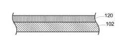
도 1은 유리 프리폼(100)의 하나의 실시예의 적층 표면의 단면이다. 유리 프리폼(100)은 다수의 유리 층을 포함하는 적층 구조를 포함한다. 예를 들어, 유리 프리폼(100)은 유리 층이 서로 인접하여 단지 적층되는 것과는 대조적으로 함께 결합되거나 융합되는 단일 적층 구조를 포함한다. 유리 프리폼(100)은 도 1에 도시된 것처럼 실질적으로 평면이거나 비-평면일 수 있다. 도 1에 도시된 실시예에서, 유리 프리폼(100)은 제1 클래딩 층(104, cladding layer)과 제2 클래딩 층(106) 사이에 배치된 코어 층(102)을 포함한다. 일부 실시예에서, 제1 클래딩 층(104)과 제2 클래딩 층(106)은 도 1에 도시된 것과 같이 외부층이다. 다른 실시예에서, 제1 클래딩 층 및/또는 제2 클래딩 층은 코어 층과 외부층 사이에 배치된 중간층이다.1 is a cross section of a laminated surface of one embodiment of a
코어 층(102)은 제1 주 표면과 제1 주 표면과 마주하는 제2 주 표면을 구비한다. 일부 실시예에서, 제1 클래딩 층(104)은 코어 층(102)의 제1 주 표면에 융합된다. 부가적으로 또는 대안으로, 제2 클래딩 층(106)은 코어 층(102)의 제2 주 표면에 융합된다. 상기 실시예에서, 제1 클래딩 층(104)과 코어 층(102) 사이 및/또는 제2 클래딩 층(106) 및 코어 층(102) 사이의 접점은 예컨대, 중합체 중간층, 접착제, 코팅층(coating layer), 또는 코어 층에 각각의 클래딩 층을 접착하도록 구성되거나 추가된 어떤 비 유리 재질과 같은 어떤 접착 재료가 없다. 따라서, 제1 클래딩 층(104) 및/또는 제2 클래딩 층(106)은 코어 층(102)에 직접 융합되거나 또는 코어 층(102)에 직접 인접한다. 일부 실시예에서, 유리 프리폼은 코어 층과 제1 클래딩 층 사이 및/또는 코어 층과 제2 클래딩 층 사이에 배치된 하나 이상의 중간층을 구비한다. 예를 들어, 중간층은 중간 유리 층 및/또는 코어 층과 클래딩 층의 접점에 형성된 확산층(diffusion layer)을 구비한다. 확산층은 확산층에 직접 인접한 각각의 층의 성분을 구비한 혼합된 구역을 구비할 수 있다. 일부 실시예에서, 유리 프리폼(100)은 직접 인접한 유리 층 사이의 접점이 유리-유리 접점인 유리-유리 적층(예, 원위치에 융합된 다층 유리-유리 적층)을 구비한다.The
일부 실시예에서, 코어 층(102)은 제1 유리 조성물을 포함하며, 제1 및/또는 제2 클래딩 층(104, 106)은 제1 유리 조성물과 다른 제2 유리 조성물을 포함한다. 예를 들어, 도 1에 도시된 실시예에서, 코어 층(102)은 제1 유리 조성물로 이루어지며, 각각의 제1 클래딩 층(104)과 제2 클래딩 층(106)은 제2 유리 조성물로 구성된다. 다른 실시예에서, 제1 클래딩 층은 제2 유리 조성물로 이루어지며, 제2 클래딩 층은 제1 유리 조성물 및/또는 제2 유리 조성물과 다른 제3 유리 조성물로 구성된다.In some embodiments, the
유리 프리폼은 예를 들어, 융합 인발(fusion draw), 하향 인발(down draw), 슬롯 인발(slot draw), 상향 인발(up draw), 또는 부유 공정과 같은 적합한 공정을 이용하여 형성될 수 있다. 일부 실시예에서, 유리 프리폼은 융합 인발 공정을 이용하여 형성된다. 도 2는 예컨대, 유리 프리폼(100)과 같은 유리 프리폼을 형성하는데 사용될 수 있는 오버플로우 분배기(200, overflow distributor)의 하나의 실시예에 대한 단면이다. 오버플로우 분배기(200)는 미국 특허 4,214,886에 개시된 것처럼 구성될 수 있으며, 그 전체가 참조로서 본원에 포함된다. 예를 들어, 오버플로우 분배기(200)는 하부 오버플로우 분배기(220)와 하부 오버플로우 분배기 위에 배치된 상부 오버플로우 분배기(240)를 구비한다. 하부 오버플로우 분배기(220)는 트로프(222, trough)를 구비한다. 제1 유리 조성물(224)은 용융되어 용융 또는 점성 상태로 트로프(222)로 공급된다. 제1 유리 조성물(224)은 하기에 더욱 자세히 설명된 것처럼 유리 프리폼(100)의 코어 층(102)을 형성한다. 상부 오버플로우 분배기(240)는 트로프(242)를 구비한다. 제2 유리 조성물(244)은 용융되고 용융 또는 점성 상태로 트로프(242)로 공급된다. 제2 유리 조성물(244)는 하기에 더욱 자세히 설명될 것처럼 유리 프리폼(100)의 제1 및 제2 클래딩 층(104, 106)을 형성한다.The glass preform may be formed using a suitable process such as, for example, fusion draw, down draw, slot draw, up draw, or float process. In some embodiments, the glass preform is formed using a fusion drawing process. 2 is a cross-section of one embodiment of an
제1 유리 조성물(224)은 트로프(222)에서 흘러나와서 하부 오버플로우 분배기(220)의 양쪽 외부 성형 표면(226, 228) 아래로 흐른다. 외부 성형 표면(226, 228)은 인발 라인(230, draw line)에서 합쳐진다. 하부 오버플로우 분배기(220)의 각각의 외부 성형 표면(226, 228) 아래로 흐르는 제1 유리 조성물(224)의 개별 스트림은 유리 프리폼(100)의 코어 층(102)을 형성하기 위해 함께 융합되는 인발 라인(230)에서 합쳐진다.The
제2 유리 조성물(244)은 트로프(242)에서 넘쳐서 상부 오버플로우 분배기(240)의 양측 외부 성형 표면(246, 248) 아래로 흐른다. 제2 유리 조성물(244)은 상부 오버플로우 분배기(240)에 의해 외부로 편향되어 제2 유리 조성물은 하부 오버플로우 분배기(220) 주위로 흐르고 하부 오버플로우 분배기의 외부 성형 표면(226, 228) 위로 흐르는 제1 유리 조성물(224)과 접촉한다. 제2 유리 조성물(244)의 개별 스트림은 하부 오버플로우 분배기(220)의 각각의 외부 성형 표면(226, 228) 아래로 흐르는 제1 유리 조성물(224)의 각각의 개별 스트림과 융합된다. 인발 라인(230)에서 제1 유리 조성물(224)의 스트림이 합쳐지면, 제2 유리 조성물(244)은 유리 프리폼(100)의 제1 및 제2 클래딩 층(104, 106)을 형성한다.The
일부 실시예에서, 용융 또는 점성 상태의 제1 유리 조성물(224)은 유리 프리폼(100)을 형성하기 위해 용융 또는 점성 상태로 제1 및 제2 클래딩 층(104, 106)의 제2 유리 조성물(244)과 접촉된다. 부가적으로, 또는 대안으로서, 유리 프리폼(100)은 도 2에 도시된 것처럼 하부 오버플로우 분배기(220)의 인발 라인(230)으로부터 멀리 이동하는 유리 리본(ribbon)을 구비한다. 유리 프리폼(100)은 예컨대, 중력 및/또는 견인 롤러(pulling rollers)를 포함하는 적합한 수단에 의해 하부 오버플로우 분배기(220)로부터 멀리 인발될 수 있다. 유리 프리폼(100)은 하부 오버플로우 분배기(220)로부터 멀리 이동하면서 냉각된다.In some embodiments, the
일부 실시예에서, 유리 프리폼(100)의 외부 표면의 한쪽 또는 모두에 코팅이 적용된다. 코팅(coating)은 액체(예, 분무 또는 침지를 통해) 또는 필름으로 도포될 수 있다. 코팅은 융합 인발된 시트의 본래 그대로의 품질을 보존하고 및/또는 손상으로부터 유리 프리폼(100)의 표면을 보호하는데 도움을 줄 수 있다. 예를 들어, 코팅은 유리 프리폼(100)이 이곳에 설명된 것처럼 감겨지는 경우 표면 대 표면 접촉을 막도록 구성된 간지(interleaf)를 포함한다.In some embodiments, the coating is applied to one or both of the outer surfaces of the
일부 실시예에서, 유리 프리폼(100)은 이곳에 명시된 것처럼 재인발 유닛으로 보내기 위해 스풀에 감겨진다. 다른 실시예에서, 유리 프리폼(100)은 오버플로우 분배기(200)에서 재인발 유닛으로 직접 이송된다. 따라서, 유리 프리폼(100)의 근접 말단부는 이곳에 명시된 것과 같이 유리 프리폼을 인발하는 동안 오버플로우 분배기(200)에 결합된 상태로 유지된다. 다른 실시예에서, 유리 프리폼(100)은 재인발 유닛으로 이송되는 유리 프리폼 세그먼트(segments)를 형성하도록 잘려진다. 유리 프리폼(100)은 예컨대, 스코어링(scoring), 굽힘, 열충격, 및/또는 레이저 절단과 같은 적절한 기술을 이용하여 절단될 수 있다.In some embodiments, the
도 1에 도시된 유리 프리폼(100)이 3개 층을 포함하긴 하지만, 다른 실시예도 본 발명에 포함된다. 다른 실시예에서, 유리 프리폼은 예컨대, 둘, 넷, 그 이상의 층과 같이, 미리 정해진 수의 층을 가질 수 있다. 예를 들어, 2개 층을 구비한 유리 프리폼은 2개의 유리 조성물이 오버플로우 분배기의 양측 외부 성형 표면 위로 흐르고 오버플로우 분배기의 인발 라인에서 합쳐지도록 각각의 오버플로우 분배기의 인발 라인으로부터 멀리 이동하면서 또는 분리된 트로프를 가진 단일 오버플로우 분배기를 이용하여 2개 층이 결합되도록 배치된 2개의 오버플로우 분배기를 이용하여 형성될 수 있다. 4개 이상의 층을 포함하는 유리 프리폼은 추가 오버플로우 분배기를 이용하여 및/또는 분리된 트로프를 가진 오버플로우 분배기를 이용하여 형성될 수 있다. 따라서, 미리 정해진 수의 층을 가진 유리 프리폼은 오버플로우 분배기를 그에 따라 수정함으로써 형성될 수 있다.Although the
일부 실시예에서, 유리 프리폼(100)은 적어도 약 0.05mm, 적어도 약 0.1mm, 적어도 약 0.2mm, 또는 적어도 약 0.3mm의 두께를 갖는다. 부가적으로, 또는 대안으로, 유리 프리폼(100)은 최대 약 5 mm, 최대 약 3 mm, 최대 약 2 mm, 최대 약 1.5 mm, 최대 약 1 mm, 최대 약 0.7 mm, 최대 약 0.5 mm, 최대 약 0.3 mm, or 최대 약 0.2 mm의 두께를 갖는다. 예를 들어, 유리 프리폼(100)은 약 0.05 mm 에서 약 5 mm, 약 0.1 mm 에서 약 1 mm, 약 0.1 mm 에서 약 0.7 mm, 또는 약 0.1 mm 에서 약 0.3 mm의 두께를 갖는다. 유리 프리폼(100)의 각 유리 층의 프리폼 두께 비는 각각의 유리 층의 두께와 유리 프리폼의 두께의 비를 포함한다. 일부 실시예에서, 코어 층(102)의 프리폼 두께 비는 적어도 약 0.5, 적어도 약 0.7, 적어도 약 0.8, 적어도 약 0.85, 적어도 약 0.9, 또는 적어도 약 0.95이다. 부가적으로, 또는 대안으로, 코어 층(102)의 두께 비는 최대 약 0.8, 최대 약 0.75, 최대 약 0.7, 최대 약 0.6, 또는 최대 약 0.5이다.In some embodiments, the
유리 프리폼은 유리 프리폼보다 더 얇은 인발된 유리 시트를 형성하도록 인발될 수 있다. 상기 공정은 재인발 또는 재성형 공정으로서 설명될 수 있다. 일부 실시예에서, 유리 프리폼은 재인발 시스템을 이용하여 인발된다. 도 3은 예컨대, 유리 프리폼(100)과 같은 유리 프리폼을 인발하는데 사용될 수 있는 재인발 시스템(300)의 하나의 실시예에 대한 개략도이다. 재인발 시스템(300)은 공급 유닛(310), 인발 유닛(330) 및 수집 유닛(350)을 구비한다.The glass preform can be drawn to form a drawn glass sheet thinner than the glass preform. This process can be described as a re-injection or re-forming process. In some embodiments, the glass preform is drawn using a reinforcement system. 3 is a schematic diagram of one embodiment of a
일부 실시예에서, 공급 유닛(310)은 도 3에 도시된 것처럼 이송 스풀(312, spool)을 구비한다. 유리 프리폼(100)은 이송 스풀(312)에 제공되며 이송 스풀에서 유리 프리폼을 풀어서 인발 유닛(330)으로 공급된다. 다른 실시예에서, 유리 프리폼은 유리 프리폼 세그먼트 또는 시트 형태로 제공되며 인발 유닛으로 프리폼 세그먼트를 진행시킴으로써 인발 유닛(330)으로 이송된다. 예를 들어, 유리 프리폼 시트는 인발 유닛으로 프리폼 시트를 전진시키는 고정 장치(holding device)에 의해 지지된다. 또 다른 실시예에서, 유리 프리폼은 유리 프리폼 리본 형태(예, 성형 유닛에 연결된)로 제공되며 프리폼 리본의 말단부를 인발 유닛으로 전진시킴으로써 인발 유닛(330)으로 이송된다.In some embodiments, the
일부 실시예에서, 공급 유닛(310)은 유리 프리폼(100)의 하나 이상의 표면으로부터 코팅을 제거하도록 구성된 스트립 유닛(314, stripping unit)을 구비한다. 예를 들어, 도 3에 도시된 실시예에서, 스트립 유닛(314)은 유리 프리폼(100)의 양쪽 표면에서 필름을 제거하도록 구성된 한 쌍의 스트립 롤러(316, roller)를 구비한다. 다른 실시예에서, 스트립 유닛은 스크럽 유닛(scrubbing unit)(예, 브러쉬), 스프레이 유닛(spraying unit)(예, 용액을 분무하기 위한), 가열 및/또는 냉각 유닛, 또는 다른 적합한 코팅 또는 필름 제거 유닛을 구비한다. 스트립 유닛(314)은 유리 프리폼이 인발 유닛(330)으로 도입될 때 유리 프리폼(100)과 맞물리기 위해 이송 스풀(312)의 말단부 또는 하류에 배치된다.In some embodiments, the
일부 실시예에서, 공급 유닛(310)은 유리 프리폼(100)의 하나 이상의 표면 상에 전하 형성을 분산시키도록 구성된 대전 방지 장치(318)를 포함한다. 예를 들어, 유리 프리폼의 표면으로부터 필름을 제거하는 도중 유리 프리폼의 표면에 정전하(static charge)가 형성될 수 있다. 대전 방지 장치(318)는 정전하가 유리 프리폼에서 제거되도록 분산시키기 위한 전전하에 대한 경로를 제공할 수 있다. 대전 방지 장치(318)는 정적 바(bar), 이온화기 또는 다른 적절한 정전 소산 장치를 포함한다. 대전 방지 장치(318)는 유리 프리폼이 인발 유닛(330)으로 도입될 때 유리 프리폼(100)과 맞물리기 위해 이송 스풀(312) 및/또는 스트립 유닛(314)의 하류 또는 말단부에 배치된다.In some embodiments, the
일부 실시예에서, 공급 유닛(310)은 유리 프리폼(100)을 인발 유닛(330)으로 구동 또는 도입시키도록 구성된 공급 구동 유닛(320)을 구비한다. 예를 들어, 도 3에 도시된 실시예에서, 공급 구동 유닛(320)은 유리 프리폼을 이송 스풀(312)에서 인발 유닛(330)으로 당기기 위한 유리 프리폼(100)의 양쪽 표면과 맞물리는 한 쌍의 구동 롤러를 구비한다. 구동 롤러는 그 사이에 유리 프리폼(100)을 맞물고 말단부 방향으로 유리 프리폼을 끌어당기도록 회전한다. 다른 실시예에서, 공급 구동 유닛은 구동 벨트(drive belts), 그립 아암(gripping arms), 또는 다른 적합한 구동 장치를 구비한다. 공급 구동 유닛(320)은 공급 속도로 인발 유닛(330)으로 유리 프리폼(100)을 도입한다. 예를 들어, 공급 속도는 유리 프리폼(100)이 인발 유닛(330)으로 도입될 때 말단부 방향으로 이송하는 속도를 포함한다. 공급 구동 유닛(320)은 공급 속도를 조절하도록 조절될 수 있다. 예를 들어, 구동 롤러의 회전 속도는 공급 속도를 증가시키도록 증가되거나 공급 속도를 감소시키도록 감속될 수 있다. 공급 구동 유닛(320)은 유리 프리폼(100)을 인발 유닛(300)으로 도입하기 위해 이송 스풀(312), 스트립 유닛(314), 및/또는 대전 방지 장치(318)의 말단 또는 하류에 배치된다.In some embodiments, the
일부 실시예에서, 공급 유닛(310), 또는 그 일부분은 공급 인클로저(322, feed enclosure) 내에 둘러싸이며, 이는 공급 유닛(310)의 다양한 구성을 둘러싸며 제어된 환경을 유지하는데 도움을 줄 수 있다. 예를 들어, 공급 인클로저(322)는 인발 유닛(330)으로 유리 프리폼(100)이 도입될 때 유리 프리폼(100)에 증착된 외부 입자 및/도는 오염물질을 막는 클린룸(cleanroom)을 구비한다. 일부 실시예에서, 공급 인클로저(322)는 그 안에 불활성 대기를 포함한다. 부가적으로, 또는 대안으로, 공급 인클로저(322)는 그 안에 정전기 축적을 줄이도록 구성된다.In some embodiments, the
일부 실시예에서, 공급 유닛(310)은 인발 유닛(330) 인근에 배치된 구멍 조절 장치(324)를 구비한다. 예를 들어, 구멍 조절 장치(324)는 공급 인클로저(322)의 출구 및/또는 인발 유닛(330)의 입구에 배치된다. 구멍 조절 장치(324)는 유리 프리폼(100)이 인발 유닛(330)으로 도입되는 개구부의 크기를 조절하는데 도움을 줄 수 있다. 도 3에 도시된 실시예에서, 구멍 조절 장치(324)는 개구부를 줄이도록 서로를 향해 움직일 수 있으며 개구부를 확대하기 위해 서로에게서 멀어지도록 움직일 수 있는 한 쌍의 슬라이딩 도어(sliding doors)를 구비한다. 다른 실시예에서, 구멍 조절 장치는 셔터(shutter), 조리개(iris), 또는 다른 적합한 장치를 포함한다. 구멍 조절 장치(324)는 공급 인클로저와 인발 유닛 사이의 가스 유동(예, 공기 유동)을 차단하기 위해, 공급 인클로저(322)와 인발 유닛(330) 사이의 개구부를 밀봉하는데 도움을 줄 수 있으며, 개구부를 통해 휩쓸려 들어올 외부 입자 및/또는 오염물질에 대한 가능성을 줄일 수 있다.In some embodiments, the
인발 유닛(330)은 유리 프리폼(100)이 전술한 것처럼, 공급 유닛으로부터 인발 유닛으로 말단 방향으로 종방향으로 전진될 수 있도록 공급 유닛(310)의 말단부 또는 하류에 배치된다. 인발 유닛(330)은 유리 프리폼이 유리 시트로 인발될 수 있도록 유리 프리폼의 일부분을 가열하고 및/또는 유리 시트가 인발된 이후 인발된 유리 시트의 일부분을 냉각하도록 구성된, 노(furnace), 유리 융해로, 또는 다른 적합한 가열 유닛을 구비한다. 일부 실시예에서, 인발 유닛(330)은 다수의 가열 및/또는 냉각 존을 구비하며, 각각은 인발 유닛을 통해 지나가면서 유리 프리폼의 일부분 및/또는 인발된 유리 시트를 가열 또는 냉각하도록 구성된다. 예를 들어, 도 3에 도시된 실시예에서, 인발 유닛(330)은 예열 존(332), 가열 존(334), 및 냉각 존(336)을 구비한다. 인발 유닛(330)의 각각의 가열 및/또는 냉각 존은 가열 플레이트(예, 인덕션 플레이트(induction plate) 및/또는 저항 히터), 적외선 가열 장치, 전자기 가열 장치, 토치(torch, 레이저, 유체 제트(예, 에어제트 또는 워터제트), 또는 다른 적절한 가열 또는 냉각 장치를 구비한다. 부가적으로, 또는 대안으로, 하나 이상의 가열 및/또는 냉각 존은 가열 및/또는 냉각 부재와 유리 프리폼(110) 사이에 배치된 열 확산기(thermal spreader)를 구비한다. 열 확산기는 유리 프리폼의 간접 가열 및/또는 냉각을 야기하여 유리 프리폼을 균일하게(예를 들어, 유리 프리폼의 폭을 가로 질러) 가열 및/또는 냉각시키는 것을 돕는다. 다른 실시예에서, 인발 유닛은 추가 가열 및/또는 냉각 존을 구비할 수 있으며, 또는 하나 이상의 가열 및/또는 냉각 존(예컨대, 예열 존 및/또는 냉각 존)이 생략될 수 있다.The
예열 존(332)은 유리 프리폼의 예열된 부분을 형성하기 위해 예열 온도로 유리 프리폼(100)의 일부를 가열하도록 구성된다. 일부 실시예에서, 예열 온도는 복수의 유리 층 중 가장 높은 변형 점보다 크거나 같다. 이곳에 사용된 것처럼, 유리 층의 "변형 점"은 유리 층의 점도가 1014.7포아즈(poise)인 온도이다. 예열 유닛(332)은 예열 속도로 유리 프리폼(100)의 일부를 예열 온도로 가열한다. 예를 들어, 예열 속도는 약 5°C/min 에서 약 200°C/min, 약 5°C/min 에서 약 100°C/min, 약 10°C/min 에서 약 50°C/min, 또는 약 15°C/min 에서 약 30°C/min 이다. 일부 실시예에서, 예열 속도는 실질적으로 유리 프리폼의 CTE 곡선과 일치한다. 예를 들어, 예열 중 시간의 함수로서 유리 프리폼(100)의 일부분의 온도의 기울기는 온도의 함수로서 유리 프리폼의 유효 CTE의 기울기와 실질적으로 동일하다. 이 경우 CTE는 평균 CTE와 반대되는 절대 CTE를 의미한다. 예열 속도를 제어하면 유리 프리폼에 열 응력이 유입되는 것을 피할 수 있으므로 유리 프리폼이 깨지거나 흔들릴 수 있다.The preheating
가열 존(334)은 유리 프리폼(100)의 말단부를 감쇠 온도로 가열하도록 구성된다. 일부 실시예에서, 가열 존(334)은 예열 존(332)의 말단 또는 하류에 위치되어 유리 프리폼(100)의 예열된 부분이 말단 방향으로 가열 존 내로 종방향으로 전진한다. 예를 들어, 가열 존(334)은 유리 프리폼의 가열된 부분을 형성하기 위해 유리 프리폼(100)의 예열된 부분을 감쇠 온도로 가열하도록 구성된다. 일부 실시예에서, 감쇠 온도는 복수의 유리 층의 최고 연화점보다 크거나 같다. 부가적으로 또는 대안적으로 감쇠 온도는 감쇠 온도에서 유리 프리폼의 중앙 영역의 유효 점도가 약 100 kP 내지 약 10,000 kP가 되도록 한다. 일부 실시예에서, 제1 유리 조성물과 제2 유리 조성물 사이의 점도 차이는 본원에서 기술된 바와 같은 두께 비율을 유지하면서 비교적 높을 수 있다. 예를 들어, 제1 유리 조성물과 제2 유리 조성물 사이의 점도 차이는 약 5 kP 이하, 예컨대 약 0 kP 내지 약 5 kP 또는 약 1 kP 내지 약 5 kP이다. 이는 제1 유리 조성물 및 제2 유리 조성물이 유리 프리폼을 인발하는 동안 서로에 대해 유동하지 않음을 시사한다. 가열 존(334)은 유리 프리폼(100)을 가열 속도로 감쇠 온도로 가열한다. 예를 들어, 가열 속도는 약 5°C/min 에서 약 200°C/min, 약 5°C/min 에서 약 100°C/min, 약 10°C/min 에서 약 50°C/min, 또는 약 15°C/min 에서 약 30°C/min 이다.The
일부 실시예에서, 가열 존(334)은 유리 프리폼(100)의 가열된 부분이 길이 방향으로 비교적 짧은 길이를 갖도록 구성된다. 예를 들어, 유리 프리폼(100)의 가열된 부분은 횡방향으로 연장되는 폭(유리 프리폼(100)의 폭에 상응하는)과 종방향으로 연장되는 길이(유리 예비 형성 체의 길이에 상응하는)를 포함하고, 가열된 부분의 높이는 약 10 cm 이하, 약 5 cm 이하, 약 3 cm 이하 또는 약 0.5 cm 이하이다. 따라서, 가열 속도는 유리 프리폼(100)의 가열된 부분이 비교적 짧게 유지되도록 충분히 높다. 이러한 짧은 가열된 부분은 가열된 부분에서 유리 프리폼(100)의 폭을 유지하는 것을 도울 수 있고 및/또는 유리 프리폼을 인발된 유리 시트 내로 인발하는 동안 도움을 줄 수 있다. 예를 들어, 이러한 짧은 가열 된 부분은 유리 프리폼의 인발 중에 유리 프리폼(100)의 에지가 안쪽으로 당겨지는 것을 방지할 수 있다. 부가적으로 또는 대안으로, 유리 프리폼이 가열 존으로 공급되는 속도 및/또는 가열된 존으로부터 회수된 유리 시트가 인발되는 속도는 유리 프리폼 및/또는 인발된 유리 시트가 가열 영역에 노출되는 시간을 줄이기 위해 증가될 수 있다. 따라서, 가열 존의 유효 길이는 유리 프리폼 및/또는 인발된 유리 시트가 가열 존을 통과하는 속도를 증가시킴으로써 단축될 수 있다. 일부 실시예에서, 유리 프리폼(100)의 가열된 부분의 온도는 유리 프리폼의 예열된 부분의 온도보다 적어도 약 100 ℃, 적어도 약 150 ℃, 또는 적어도 약 200 ℃ 더 크다. 유리 프리폼의 예열 된 부분의 온도 및 유리 프리폼의 감쇠 영역의 가열 된 부분의 온도가 너무 가까운 경우, 예비 가열 존에서 감쇠가 발생할 수 있다. 예열 온도는 유리가 부분적으로 이완될 수 있도록 충분히 높아야 하지만 예열 영역에서 유리가 약화되지 않도록 충분히 낮아야 하며 유리는 감쇠 온도로 빠르게 가열되어야 합니다. 따라서, 가열 영역은 비교적 짧은 종방향 거리에 걸쳐 유리 프리폼의 온도를 신속하게 변화시키도록 구성된다.In some embodiments, the
유리 프리폼(100)은 종방향(화살표 (338)로 도시됨)으로 종방향으로 인발되어 도 3에 도시된 바와 같이 유리 프리폼으로부터 말단방향으로 연장된 인발된 유리 시트(110)를 형성한다. 예를 들어, 유리 프리폼(100)의 가열된 부분은 말단 방향(338)으로 인발 또는 당겨지고, 유리 프리폼의 말단부가 연장되어 인발된 유리 시트(110)를 형성하게 한다. 따라서, 인발된 유리 시트(110)는 복수의 유리 층을 구비하고, 인발된 유리 시트의 두께는 유리 프리폼(100)의 두께보다 작다. 예를 들어, 인발된 유리 시트(110)는 도 1에 도시되고 유리 프리폼(100)에 대해 설명된 적층 구조를 포함한다. 일부 실시예에서, 인발된 유리 시트(110)의 두께에 대한 유리 프리폼(100)의 두께의 비는 적어도 약 2, 적어도 약 5, 적어도 약 10, 적어도 약 20, 적어도 약 30, 적어도 약 50, 적어도 약 100, 또는 적어도 약 200이다. 부가적으로 또는 대안으로, 인발된 유리 시트(110)의 두께에 대한 유리 프리폼(100)의 두께의 비는 최대 약 300이다.The
일부 실시예에서, 인발된 유리 시트(110) 두께는 최대 약 0.7 mm, 최대 약 0.5 mm, 최대 약 0.3 mm, 최대 약 0.2 mm, 최대 약 0.1 mm, 최대 약 0.05 mm, 최대 약 0.03 mm, 약 0.02 mm 또는 약 0.01 mm 일 수 있다. 부가적으로 또는 대안으로, 인발된 유리 시트(110)는 적어도 약 0.001 mm, 적어도 약 0.01 mm 또는 적어도 약 0.05 mm의 두께를 갖는다. 인발된 유리 시트(110)의 각 유리 층의 시트 두께 비는 인발된 유리 시트의 두께에 대한 각 유리 층의 두께의 비율을 포함한다. 시트 두께 비는 이곳에 기술된 바와 같이 인발된 유리 시트로부터 임의의 유리 층을 제거하기 전에 계산된다. 일부 실시예에서, 각 유리 층의 시트 두께 비는 각 유리 층의 프리폼 두께 비와 동일하거나 실질적으로 동일하다. 즉, 유리 프리폼(100)을 인발된 유리 시트(110)로 인발할 때 유리 층의 상대 두께는 실질적으로 변화하지 않는다. 예를 들어, 각 유리 층의 시트 두께 비는 각각의 유리 층의 프리폼 두께 비의 약 20 % 이내, 약 15 % 이내, 약 10 이내 약 5 % 이내, 또는 약 2 % 이내이다. 따라서, 일부 실시예에서, 코어 층(102)의 시트 두께 비는 적어도 약 0.7, 적어도 약 0.8, 적어도 약 0.85, 적어도 약 0.9, 또는 적어도 약 0.95이다. 부가적으로 또는 대안으로, 코어 층(102)의 시트 두께 비는 최대 약 0.8, 최대 약 0.75, 최대 약 0.7, 최대 약 0.6 또는 최대 약 0.5이다.In some embodiments, the drawn
도 3으로 돌아가서, 일부 실시예에서, 인발 유닛(330)은 유리 프리폼(100) 및/또는 인발된 유리 시트(110)를 횡방향 및/또는 종방향으로 인장되도록 구성된 에지 가이드 유닛(340, edge guiding unit)을 구비한다. 예를 들어, 도 3에 도시된 실시예에서, 에지 가이드 유닛(340)은 에지를 향해 바깥으로 인발된 유리 시트를 당기고 인발된 유리 시트를 횡방향으로 인장시키기 위해 인발된 유리 시트(110)의 양쪽 에지와 맞물리도록 구성된 쌍의 에지 롤러(단지 한 쌍으로만 도시됨)를 구비한다. 다른 실시예에서, 에지 가이드 유닛은 벨트, 그립 아암(gripping arm), 또는 다른 적합한 에지 결합(맞물림) 장치를 구비한다. 또 다른 실시예에서, 에지 가이드 유닛은 인발된 유리 시트를 에지를 향해 바깥쪽으로 당기고 횡방향으로 인발된 유리 시트를 인장시키기 위해 인발된 유리 시트의 양쪽 에지 구역을 선택적으로 냉각시키도록 구성된 하나 이상의 냉각 장치(예, 유체 제트, 냉각 라디에이터 튜브(cooling radiator tube), 또는 다른 적합한 냉각 장치)를 구비한다. 에지 가이드 유닛(340)은 가열 존(334)에 배치될 수 있다. 따라서, 에지 가이드 유닛(340)은 유리 시트가 충분히 높은 온도에서 인장력을 받으면서 늘어나거나 변형되면서 인발된 유리 시트(110)를 인장시킨다. 부가적으로, 또는 대안으로, 에지 가이드 유닛(340)은 에지 사이에 배치된 인발된 유리 시트의 중앙 구역과 맞물리지 않고 인발된 유리 시트의 양쪽 에지에서 인발된 유리 시트(100)와 맞물릴 수 있다. 따라서, 인발된 유리 시트의 맞물리지 않은 중앙 구역은 에지 가이드 유닛과 접촉에 의해 야기된 결함이 남아있지 않는다. 에지 냉각 및/또는 당김(예, 가열 존에서)은 좌굴을 방지하고 횡방향으로의 약화를 최소화하는데 도움을 줄 수 있다.3, in some embodiments, the
냉각 존(336)은 인발된 유리 시트(110)의 일부분을 냉각 온도로 냉각시키도록 구성된다. 일부 실시예에서, 냉각 존(336)은 가열 존(334)의 말단부 또는 하류에 배치되어 유리 프리폼(100)의 가열된 부분에 인접한 인발된 유리 시트(110)의 말단부가 냉각 존으로 말단방향으로 전진된다. 예를 들어, 냉각존(336)은 인발된 유리 시트(110)의 말단 부분을 냉각 온도로 냉각시키도록 구성된다. 일부 실시예에서, 냉각 온도는 유리 층의 유리 조성에 기초하며 인발된 유리 시트의 형태 및 응력을 최소화하도록 맞춰진다. 부가적으로 또는 대안으로, 냉각 온도는 다수의 유리 층의 최고 변형 점보다 낮거나 같다. 냉각존(336)은 인발된 유리 시트(110)를 냉각 속도로 냉각 온도로 냉각시킨다. 일부 실시예에서, 냉각 속도는 점탄성 구역 아래에 있을 때보다 유리가 점탄성 구역을 통해 지나갈 때 더 높다. 부가적으로 또는 대안으로, 냉각 속도는 CTE 곡선 및/또는 예열 속도와 일치할 수 있다. 인발된 유리 시트의 말단부의 상기 제어된 냉각은 인발된 유리 시트의 폭을 설정하는 것을 돕기에 충분히 빠르며 열적으로 유도된 형상 뒤틀림 및/또는 응력을 최소화하기 충분히 느릴 수 있다.The
일부 실시예에서, 인발 유닛(330)은 인발 유닛(330)으로부터 인발된 유리 시트(110)를 구동하거나 뽑아내도록 구성된 인발 구동 유닛(342)을 구비한다. 예를 들어, 도 3에 도시된 실시예에서, 인발 구동 유닛(342)은 인발 유닛(330)을 통해 인발된 유리 시트를 잡아당기기 위해 인발된 유리 시트(110)의 양쪽 표면과 맞물리는 한 쌍의 구동 롤러를 구비한다. 구동 롤러는 그 사이에 인발된 유리 시트(110)와 맞물리고 말단방향으로 종방향으로 인발된 유리 시트를 잡아당기도록 회전한다. 다른 실시예에서, 인발 구동 유닛은 벨트, 그리핑 아암, 또는 다른 적합한 구동 장치를 구비한다. 인발 구동 유닛(342)은 인발된 유리 시트(110)를 인발 유닛(330)으로부터 인발 속도로 구동 또는 뽑아낸다. 예를 들어, 인발 속도는 유리 시트가 인발 유닛(330)에서 뽑아내질 때 인발된 유리 시트(110)가 말단방향으로 이동하는 속도를 포함한다. 인발 구동 유닛(342)은 인발 속도를 조절하도록 조절될 수 있다. 예를 들어, 구동 롤러의 회전 속도는 인발 속도를 증가시키기 위해 증가되거나 인발 속도를 감소시키기 위해 감소될 수 있다. 일부 실시예에서, 인발 속도는 공급 속도보다 더 크다. 따라서, 인발된 유리 시트(110)는 유리 프리폼(100)이 인발 유닛으로 도입되는 것보다 더 빠르게 인발 유닛으로부터 뽑아내진다. 일부 실시예에서, 공급 속도에 대한 인발 속도의 비는 인발된 유리 시트의 두께에 대한 유리 프리폼의 두께의 비율과 실질적으로 동일하다. 예를 드러, 하향 인발 비와 속도 비 사이는 거의 선형 관계에 있을 수 있다. 상기 인발 속도와 공급 속도 사이의 관계는 유리 프리폼의 가열된 말단 구역을 잡아당겨서 거기에서 연장된 인발된 유리 시트를 형성하는데 도움을 줄 수 있다. 인발 구동 유닛(342)은 예열 유닛(332), 가열 유닛(334) 및/또는 냉각 유닛(336)의 말단부 또는 하류에 위치되어 인발 유닛(330)으로부터 인발된 유리 시트(110)를 뽑아낸다. 예를 들어, 인발 구동 유닛(342)은 냉각 유닛(336)에 또는 냉각 유닛의 말단부 또는 하류에 배치되어 약화 온도 이하의 온도(예를 들어, 냉각 온도)에 있는 인발된 유리 시트(110)의 영역과 결합한다.In some embodiments, the
일부 실시예에서, 인발 유닛(330), 또는 그 일부분은 인발 인클로저(344, drawing enclosure) 내에 둘러싸여 있어서, 인발 유닛의 다양한 구성을 둘러싸는 제어된 환경을 유지하는데 도움을 줄 수 있다. 예를 들어, 인발 인클로저(344)는 클린룸 및/또는 불활성 대기를 포함한다.In some embodiments, the
수집 유닛(350)은 인발 유닛(330)의 말단부 또는 하류에 위치되어 인발된 유리 시트(110)는 이곳에 설명된 것처럼 인발 유닛으로부터 수집 유닛으로 전진될 수 있다. 일부 실시예에서, 수집 유닛(350)은 인발 유닛(330) 근처에 배치된 구멍 제어 장치(352)를 구비한다. 예를 들어, 구멍 조절 장치(352)는 인발 인클로저(344)의 출구 및/또는 수집 유닛(350)의 입구에 배치된다. 구멍 조절 장치(352)는 수집 유닛(350)으로 인발된 유리 시트(110)가 도입되면서 개구부의 크기를 조절하는데 도움을 줄 수 있다. 구멍 조절 장치(352)는 구멍 조절 장치(324)를 참고하여 이곳에 설명된 것과 같이 구성될 수 있다.The collecting
일부 실시예에서, 수집 유닛(350)은 인발 유닛(330)으로부터 및/또는 수집 유닛을 통하여 인발된 유리 시트(110)를 구동시키고 또는 뽑아내도록 구성된 수집 구동 유닛(354)을 구비한다. 수집 구동 유닛(354)은 인발 구동 유닛(342)을 참고하여 이곳에 설명된 것처럼 일반적으로 구성될 수 있다. 예를 들어, 도 3에 도시된 실시예에서, 수집 구동 유닛(354)은 인발 유닛(330) 및/또는 수집 유닛(350)을 통해 인발된 유리 시트를 구동하기 위해 인발된 유리 시트(110)의 양쪽 표면을 맞잡는 한 쌍의 구동 롤러를 구비한다. 수집 구동 유닛(354)은 구동 속도를 조절하도록 조절될 수 있다.In some embodiments, the collecting
일부 실시예에서, 수집 유닛(350)은 인발된 유리 시트(110)의 두께를 측정하도록 구성된 두께 측정 장치(356)를 구비한다. 두께 측정 장치는 레이저 측정 장치, 초음파 측정 장치, 간섭계, 또는 다른 적합한 측정 장치를 포함한다. 일부 실시예에서, 재인발 시스템(300)의 하나 이상의 변수는 측정된 두께에 대해 조절될 수 있다. 예를 들어, 측정된 두께가 목표 두께 이하인 경우, 공급 속도에 대한 인발 속도의 비는 감소될 수 있으며, 인발된 유리 시트(110)의 두께를 증가시킬 수 있다. 대안으로, 측정된 두께가 목표 두께 이상인 경우, 공급 속도에 대한 인발 속도의 비는 증가될 수 있으며, 인발된 유리 시트(110)의 두께를 감소시킬 수 있다.In some embodiments, the collecting
일부 실시예에서, 수집 유닛(350)은 인발된 유리 시트(110)의 결점을 탐지하도록 구성된 결점 탐지 장치(358)을 구비한다. 결점 탐지 장치(358)는 카메라 시스템, 간섭 프린지 패턴 시스템(interference fringe pattern system), 반사 시스템, 또는 다른 적합한 탐지 시스템을 구비한다.In some embodiments, the
일부 실시예에서, 수집 유닛(350)은 인발된 유리 시트(110)의 외부 표면 중 하나 또는 둘 모두에 코팅을 도포하도록 구성된 코팅 도포 장치(360)를 구비한다. 코팅 도포 장치(360)는 액체 코팅 장치(예, 분무 장치, 증발 도포 장치, 침지 장치, 브러싱 장치), 필름 도포 장치(예, 롤러), 융착 장치(예, 열 융착 장치), 또는 다른 적합한 도포 장치를 구비한다. 코팅은 손상으로부터 인발된 유리 시트(110)의 표면을 보호하고 및/또는 인발된 시트의 본래의 품질을 유지하는데 도움을 줄 수 있다. 예를 들어, 코팅은 인발된 유리 시트(110)가 이곳에 설명된 것과 같이 감겨있는 경우, 표면 대 표면 접촉을 막도록 구성된 간지를 구비한다. 코팅은 예컨대, 중합체와 같은 적절한 코팅 재료를 포함한다.In some embodiments, the collecting
일부 실시예에서, 수집 유닛(350)은 인발된 유리 시트(110)를 절단하도록 구성된 절단 장치(362)를 구비한다. 절단 장치(362)는 스코어 휠(score wheel), 스크라이브 팁(scribing tip), 절삭 디스크(cutting disk), 레이저, 토치(torch), 유제 제트(fluid jet), 굽힘 장치, 다른 적합한 절단 장치, 또는 이들의 조합을 구비한다. 일부 실시예에서, 절단 장치는 종방향으로(예, 인발된 유리 시트의 폭을 조절하고 및/또는 인발된 유리 시트로부터 비드를 제거하기 위해) 인발된 유리 시트(110)를 절단한다. 부가적으로, 또는 대안으로, 절단 장치(362)는 인발된 유리 시트(110)를 따라 다른 횡방향 위치에 위치한 다수의 절단 장치를 포함한다. 예를 들어, 절단 장치(362)는 인발된 유리 시트(110)의 제1 에지 근처에 위치한 제1 절단 장치와 제1 에지 맞은편의 인발된 유리 시트의 제2 에지 근처에 배치된 제2 절단 장치를 구비한다. 제1 절단 장치와 제2 절단 장치 각각은 종방향으로 인발된 유리 시트(110)를 절단할 수 있다. 따라서, 인발된 유리 시트(110)의 각 에지에 배치된 상대적으로 얇은 구역 또는 비드(bead)는 비드 사이에 배치된 인발된 유리 시트의 중앙 영역으로부터 제거될 수 있다.In some embodiments, the collecting
일부 실시예에서, 수집 유닛(350)은 인발된 유리 시트(110)를 감기 위한 수집 스풀(364)을 구비한다. 예를 들어, 수집 스풀(364)은 인발된 유리 시트(110)가 도 3에 도시된 것처럼 그 주위에 감겨지는 실질적으로 실린더형 바디를 구비한다. 스풀 지름은 유리 시트(110)의 굽힘 반경을 기초할 수 있다. 예를 들어, 얇은 유리 시트는 두꺼운 유리 시트보다 더 작은 굽힘 반경을 가질 수 있다. 따라서, 두꺼운 유리 시트는얇은 유리 시트보다 더 큰 지름의 스풀에 수집될 수 있다. 실린더형 바디는 원형 단면 형태를 포함한다. 다른 실시예에서, 수집 스풀의 단면은 삼각형, 직사각형, 타원, 또는 다른 적합한 다각형 또는 비-다각형 형태일 수 있다. 일부 실시예에서, 수집 스풀(364)은 그 축을 중심으로 회전할 수 있다. 상기 회전은 수집 스풀(354)을 중심으로 인발된 유리 시트(110)를 감고 및/또는 인발된 유리 시트를 인발 유닛(330) 및/또는 수집 유닛(350)을 통해 당기는데 도움을 줄 수 있다. 일부 실시예에서, 수집 스풀(354)에 인발된 유리 시트(110)을 감는 것은 인발된 유리 시트의 자유로운 고리형태(366, free loop)를 유지하고 및/또는 수집 구동 유닛(354)과 수집 스풀 사이의 인장을 유지함으로써 수집된다.In some embodiments, the collecting
일부 실시예에서, 수집 유닛(350), 또는 그 일부분은 수집 인클로저(368) 내에 둘러싸이며, 수집 유닛의 다양한 구성을 둘러싸며 제어된 환경을 유지하는데 도움을 줄 수 있다. 예를 들어, 수집 인클로저(358)는 그 안에 클린룸 및/또는 불활성 대기를 포함한다.In some embodiments, the
일부 실시예에서, 인발된 유리 시트(110)는 유연한 유리 시트를 포함한다. 상기 유연한 유리 시트는 이곳에 설명된 것과 같이 수집 스풀에 인발된 유리 시트(110)의 감김을 가능하게 할 수 있다. 이곳에 설명된 공정을 이용하여 인발된 유리 시트를 성형하는 것은 인발된 유리가 실질적으로 결점(예, 칩, 균열, 스크래치, 또는 다른 결점)이 없는 본래의 외부 표면을 갖게 할 수 있다. 부가적으로, 또는 대안으로서, 인발된 유리 시트(110)는 하나 이상의 폴리싱되지 않은 외부 표면(예, 폴리싱 또는 그라인딩 처리가 가해지지 않은 외부 표면)을 포함한다. 상기 본래의 외부 표면은 인발된 유리 시트의 깨짐 없이 상대적으로 작은 굽힘 반경으로 인발된 유리 시트의 굽힘을 가능하게 한다. 예를 들어, 일부 실시예에서, 인발된 유리 시트(110)는 이론적으로 최소 굽힘 반경의 약 40% 이내, 약 30% 이내, 또는 약 20% 이내인 굽힘 반경으로 굽혀질 수 있다. 이론적 최소 굽힘 반경은 본래의 또는 결점이 없는 표면을 가진 특정 두께의 인발된 유리 시트가 깨짐 없이 굽혀질 수 있는 굽힘 반경을 나타낸다. 일부 실시예에서, 인발된 유리 시트(110)는 약 50mm보다 작거나 같고, 약 40mm보다 작거나 같고, 약 35mm보다 작거나 같고, 또는 약 30 mm보다 작거나 같고, 약 25 mm보다 작거나 같고, 약 20 mm보다 작거나 같고, 약 15 mm보다 작거나 같고, 또는 약 10 mm보다 작거나 같은 굽힘 반경으로 굽혀질 수 있다.In some embodiments, the drawn
일부 실시예에서, 인발된 유리 시트(110)는 강화된 유리 시트로서 구성된다. 예를 들어, 일부 실시예에서, 제1 및/또는 제2 클래딩 층(104, 106)의 제2 유리 조성물은 코어 층(102)의 제1 유리 조성물과 다른 평균 열팽창 계수(CTE)를 갖는다. 예를 들어, 제1 및 제2 클래딩 층(104, 106)은 코어 층(102)보다 더 낮은 평균 CTE를가진 유리 조성물로 형성된다. 이곳에 사용된 것처럼, "평균 열팽창계수"라는 용어는 0도에서 300도(℃) 사이의 주어진 재료 또는 층의 평균 열팽창계수를 나타낸다. 이곳에 사용된 것처럼, "열팽창계수"라는 용어는 달리 나타내지 않는한 평균 열팽창계수를 나타낸다. 직접 인접한 층 사이의 CTE 부조화(즉, 제1 및 제2 클래딩 층(104, 106)의 평균 CTE와 코어 층(102)의 평균 CTE 사이의 차이)는 인발 유리 스트(110)의 냉각 시 클래딩 층의 압축 응력과 코어 층의 인장 응력의 형성을 야기한다. 다양한 실시예에서, 각각의 제1 및 제2 클래딩 층은 개별적으로, 코어 층보다 높은 평균 CTE, 낮은 평균 CTE, 또는 실질적으로 같은 평균 CTE를 가질 수 있다.In some embodiments, the drawn
일부 실시예에서, 코어 층(102)의 평균 CTE와 제1 및/또는 제2 클래딩 층(104, 106)의 평균 CTE는 적어도 약 5x10⁻⁷℃-1, 적어도 약 15x10-7℃-1, 적어도 약 25x10-7℃-1, 적어도 약 30x10-7℃-1, 적어도 약 40x10-7℃-1, 또는 적어도 약 50x10-7℃-1다르다. 부가적으로 또는 대안으로, 코어 층(102)의 평균 CTE와 제1 및/또는 제2 클래딩 층(104, 106)의 평균 CTE는 최대 약 100x10-7℃-1, 최대 약 75x10-7℃-1, 최대 약 50x10-7℃-1, 최대 약 40x10-7℃-1, 최대 약 30x10-7℃-1, 최대 약 20x10-7℃-1, 또는 최대 약 10x10-7℃-1 다르다. 일부 실시예에서, 제1 및/또는 제2 클래딩 층(104, 106)의 제2 유리 조성물은 최대 약 66x10-7℃-1, 최대 약 55x10-7℃-1, 최대 약 50x10-7℃-1, 최대 약 40x10-7℃-1, 또는 최대 약 35x10-7℃-1의 평균 CTE를 포함한다. 부가적으로 또는 대안으로, 제1 및/또는 제2 클래딩 층(104, 106)의 제2 유리 조성물은 적어도 약 25x10-7℃-1, or 적어도 약 30x10-7℃-1의 평균 CTE를 포함한다. 부가적으로 또는 대안으로, 코어 층(102)의 제1 유리 조성물은 적어도 약 40x10-7℃-1, 적어도 약 50x10-7℃-1, 적어도 약 55x10-7℃-1, 적어도 약 65x10-7℃-1, 적어도 약 70x10-7℃-1, 적어도 약 80x10-7℃-1, 또는 적어도 약 90x10-7℃-1의 평균 CTE를 포함한다. 부가적으로 또는 대안으로, 코어 층(102)의 제1 유리 조성물은 최대 약 110x10-7℃-1, 최대 약 100x10-7℃-1, 최대 약 90x10-7℃-1, 최대 약 75x10-7℃-1, or 최대 약 70x10-7℃-1의 평균 CTE를 포함한다.In some embodiments, the average CTE of the
일부 실시예에서, 클래딩 층의 압축 응력은 최대 약 800 MPa, 최대 약 500 MPa, 최대 약 350 MPa, 또는 최대 약 150 MPa이다. 부가적으로 또는 대안으로, 클래딩 층의 압축 응력은 적어도 약 10 MPa, 적어도 약 20 MPa, 적어도 약 30 MPa, 적어도 약 50 MPa, 또는 적어도 약 250 MPa이다. 부가적으로 또는 대안으로, 코어 층의 인장 응력은 최대 약 150 MPa, 최대 약 120 MPa, 또는 최대 약 100 MPa이다. 부가적으로 또는 대안으로, 코어 층의 인장 응력은 적어도 약 5 MPa, 적어도 약 10 MPa, 적어도 약 25 MPa, 또는 적어도 약 50 MPa이다.In some embodiments, the compressive stress of the cladding layer is up to about 800 MPa, up to about 500 MPa, up to about 350 MPa, or up to about 150 MPa. Additionally or alternatively, the compressive stress of the cladding layer is at least about 10 MPa, at least about 20 MPa, at least about 30 MPa, at least about 50 MPa, or at least about 250 MPa. Additionally or alternatively, the tensile stress of the core layer can be up to about 150 MPa, up to about 120 MPa, or up to about 100 MPa. Additionally or alternatively, the tensile stress of the core layer is at least about 5 MPa, at least about 10 MPa, at least about 25 MPa, or at least about 50 MPa.
이곳에 명시된 재인발 방법이 인발된 유리 시트의 중앙 구역에 대해 비-접촉이며 및/또는 제어된 환경에서 수행되기 때문에, 타고난 유리 강도가 유지되고, 이는 강화된 얇은 적층 유리 구조를 생산하기 위한 이점일 수 있다. 상기 강화된 적층 유리 구조는 클래드 유리와 코어 유리의 유리 조성물의 CTE 부조화에 의해 부과된 압축 표면과 인장 내부 유리 응력을 통해 달성될 수 있거나 또는 재성형 공정 이전, 도중, 또는 이후 유리의 이온-교환을 통해 달성될 수 있다. 강화는 또한 강화된 유리 시트에 두 가지 기술의 조합으로서 실현되거나 템퍼링 방법과 조합으로 실현될 수 있다. 상기 강화된 얇은 또는 매우 얇은 적층은 굽힘, 접힘, 또는 유연한 유리 제품 또는 유리 함유 제품이 유리한 분야에서 사용될 수 있다(예, 유연한 전자 시트, 유연한 디스플레이, 유연한 커버 시트, 유연한 환경 또는 습기 차단 기판 또는 수퍼스트레이트(superstrates), 광 커넥터용 도파관, 및 유리 막).The inherent glass strength is maintained because the reclaiming method specified herein is non-contact and / or performed in a controlled environment with respect to the central zone of the drawn glass sheet, which has the advantage of producing an enhanced thin laminated glass structure Lt; / RTI > The reinforced laminated glass structure can be achieved through the compressive surface and tensile internal glass stresses imposed by the CTE mismatch of the glass composition of the clad and core glass, or can be achieved before, during, or after the re-molding process by ion- Lt; / RTI > Tempering can also be realized as a combination of the two techniques in a reinforced glass sheet or in combination with a tempering method. The reinforced thin or very thin laminate can be used in fields where bending, folding, or flexible glass products or glass-containing products are advantageous (e.g., flexible electronic sheets, flexible displays, flexible cover sheets, flexible environmental or moisture barrier substrates, Superstrates, waveguides for optical connectors, and glass membranes).
에칭 및 폴리싱 기술이 오직 노출된 표면에만 작용하기 때문에, 상기 기술들은 내부 코어 층 두께를 줄일 수 없다. 더욱이, 상기 기술은 강화된 매우 얇은 유리를 만들 때, 총 두께에 대한 코어 층 비율을 포함하는, CTE 부조화에 의해 나타난 강화 특성에 영향을 미친다. 이곳에 설명된 재인발 공정은 인발된 유리 시트가 유리 프리폼과 같은 두께 비율을 가지게 한다. 다시 말해서, 재인발 공정은 인발된 유리 시트의 유리 프리폼의 원래의 유리 두께 비율을 유지한다. 일부 실시예에서, 마이크로(micro) 또는 나노(nano) 두께는 재성형된 매우 얇은 유리로 성취될 수 있다. 예를 들어, 3개 유리 층을 초과하는 다중 유리 적층은 광학적 또는 다른 고유한 특성이 필요한 시트 내에 나노 경계를 생성하도록 재인발될 수 있다.Because the etching and polishing techniques only work on exposed surfaces, the techniques can not reduce the internal core layer thickness. Moreover, the technique affects the enhancement properties exhibited by CTE incompatibility, including the core layer ratio to total thickness, when making the reinforced ultra-thin glass. The reclaim process described herein allows the drawn glass sheet to have the same thickness ratio as the glass preform. In other words, the re-drawing process maintains the original glass thickness ratio of the glass preform of the drawn glass sheet. In some embodiments, micro or nano thicknesses can be achieved with very thin glass that has been reshaped. For example, multiple glass laminates in excess of three glass layers may be reinjected to produce nano-boundaries in sheets that require optical or other inherent properties.
일부 실시예에서, 인발된 유리 시트(110)의 복수의 유리 층 중 적어도 하나는 적어도 부분적으로 제거되어 얇은 인발된 유리 시트를 형성한다. 예를 들어, 하나 이상의 층의 인발된 유리 시트(110)는 인발된 유리 시트의 두께를 줄여서 얇은 인발된 유리 시트를 형성하기 위해 전체적으로 또는 실질적으로 전체적으로 제거된다. 일부 실시예에서, 제2 층(예컨대, 제1 클래딩 층(104) 및/또는 제2 클래딩 층(106)은 인발된 유리 층에서 적어도 부분적으로 제거된다. 예를 들어, 제1 클래딩 층(104)과 제2 클래딩 층(106) 중 하나는 인발된 유리 층(110)에서 제거되고, 2개 층의 유리 시트로서 코어 층(102)과 다른 클래딩 층을 남긴다. 일부 실시예에서, 각각의 제1 클래딩 층(104)과 제2 클래딩 층(106)은 인발된 유리 시트(110)에서 제거되고, 단일 층의 유리 시트로서 코어 층(102)을 남긴다. 일부 실시예에서, 제1 층(예, 코어 층(102))은 하나 이상의 얇은 유리 시트로서 제2 층(예, 제1 및/또는 제2 클래딩 층(104, 106))을 남기기 위해 인발된 유리 시트로부터 제거된다. 예를 들어, 코어 층(102)은 인발된 유리 시트(110)에서 제거되어, 2개의 단일 층의 유리 시트로서 제1 클래딩 층(104)과 제2 클래딩 층(106)을 남긴다.In some embodiments, at least one of the plurality of glass layers of the drawn
일부 실시예에서, 제2 층(예, 제1 클래딩 층(104) 및/또는 제2 클래딩 층(106))은 제1 층(예, 코어 층(102))보다 내구성이 낮다. 예를 들어, 도 1에 도시된 실시예에서, 제1 클래딩 층(104)과 제2 클래딩 층(106)은 코어 층(102)보다 내구성이 낮다. 제2 유리 조성물(예, 제1 및 제2 클래딩 층(104, 106)의)은 제1 유리 조성물(예, 코어 층(102)의)보다 시약에서 더 큰 분해 속도를 갖는다. 따라서, 시약에서 제1 유리 조성물의 분해 속도는 시약에서의 제2 유리 조성물의 분해 속도보다 더 작다. 일부 실시예에서, 시약에서의 제2 유리 조성물의 분해 속도는 시약에서의 제1 유리 조성물의 분해 속도에 적어도 10배이다. 일부 실시예에서, 인발된 유리 시트(110)는 코어 층(102)으로부터 제1 및/또는 제2 클래딩 층(104, 106)의 적어도 일부분을 제거하기 위해 그리고 코어 층의 외부면을 노출시키기 위해 시약과 접촉된다. 클래딩 층과 코어 층 사이의 내구성의 차이는 코어 층을 실질적으로 분해 또는 용해시키지 않고 클래딩 층을 분해 또는 용해시키기 위해 시약과 인발된 유리 시트를 접촉시킴으로써 클래딩 층이 코어 층에서 제거될 수 있게 한다.In some embodiments, the second layer (e.g.,
시약은 하나 이상의 층의 인발된 유리 시트를 분해 또는 용해할 수 있는 적절한 성분을 포함한다. 예를 들어, 시약은 산, 염기, 다른 적합한 성분, 또는 이들의 조합을 포함한다. 일부 실시예에서, 시약은 예컨대, 무기산(예, HCl, HNO3, H2SO4, H3PO4, H3BO3, HBr, HClO4, or HF), 카르복시산(carboxylic acid)(예, CH3COOH), 또는 이들의 조합과 같은 산을 포함한다. 예를 들어, 일부 실시예에서, 시약은 HCl (예, 물의 50 부피 % HCl)을 포함한다. 부가적으로 또는 대안으로, 시약은 HNO3을 포함한다. 일부 실시예에서, 시약은 예컨대, LiOH, NaOH, KOH, RbOH, CsOH, Ca(OH)2, Sr(OH)2, Ba(OH)2, 또는 이들의 조합과 같은 염기를 포함한다.The reagents include suitable components that can dissolve or dissolve one or more layers of drawn glass sheets. For example, the reagents include acids, bases, other suitable components, or combinations thereof. In some embodiments, the reagent is selected from, for example, inorganic acids (e.g., HCl, HNO3 , H2 SO4 , H3 PO4 , H3 BO3 , HBr, HClO4 , or HF), carboxylic acids CH3 COOH), or contains an acid such as a combination of the two. For example, in some embodiments, the reagent comprises HCl (e.g., 50 vol% HCl in water). Additionally or alternatively, the reagent comprises HNO3 . In some embodiments, the reagent includes a base such as LiOH, NaOH, KOH, RbOH, CsOH, Ca (OH)2 , Sr (OH)2 , Ba (OH)2 , or combinations thereof.
일부 실시예에서, 시약은 실질적으로 HF가 없다. HF는 많은 다양한 산소와 반응할 수 있으므로, 대부분의 유리 조성물과 매우 반응성이 높다. 예를 들어, HF는 가스 또는 수용성 실리콘 불화물(gaseous or water-soluble silicon fluorides)을 형성하기 위해 이산화규소와 반응한다. HF를 포함하는 시약과 인발된 유리 시트의 코어 층과의 접촉은 코어 층과 HF의 반응 할 수 있으며, 이는 코어 층 표면의 거칠기 또는 손상을 유발할 수 있다. 실질적으로 HF가 없는 시약을 사용하는 것은 시약과 코어 층의 실질적인 반응을 방지하여 코어 층 표면을 손상시키지 않고 코어 층으로부터 클래딩 층을 제거할 수 있다.In some embodiments, the reagent is substantially free of HF. HF is highly reactive with most glass compositions because it can react with many different types of oxygen. For example, HF reacts with silicon dioxide to form gaseous or water-soluble silicon fluorides. Contact between the reagent comprising HF and the core layer of the drawn glass sheet can react with the core layer and HF, which can cause roughness or damage to the surface of the core layer. The use of a substantially HF-free reagent can prevent substantial reaction of the reagent and the core layer, thereby removing the cladding layer from the core layer without damaging the core layer surface.
일부 실시예에서, 이온 교환은 제2 층(예, 제1 및/또는 제2 클래딩 층(104, 106))과 제1 층(예, 코어 층(102)) 사이에서 야기된다. 예를 들어, 코어 층(102)에 존재하는 더 작은 양이온(예, 1가 알칼리 금속 양이온 또는 2가 알칼리 토금속 양이온)은 제1 클래딩 층(104) 및/또는 제2 클래딩 층(106)에 존재하는 큰 양이온(예, 1가 알칼리 금속 양이온, 2가 알칼리 토금속 양이온 또는 Ag+)으로 교체할 수 있다. 예를 들어, 일부 실시예에서, 코어 층(102)에 존재하는 Na+는 제1 클래딩 층(104) 및/또는 제2 클래딩 층(106)에 존재하는 K+로 대체된다. 더 작은 양이온과 더 큰 양이온은 동일한 원자가 또는 산화 상태를 가질 수 있다. 작은 양이온과 큰 양이온의 교체는 압축 또는 압축 응력(CS) 하에 있는 코어 층(102)의 표면 층을 생성한다. 표면 층은 층의 깊이(DOL)까지 코어 층(102)의 내부 또는 벌크로 연장된다. 이는 제1 클래딩 층(104) 및/또는 제2 클래딩 층(106)의 제거 이후 얇아진 인발된 유리 시트(예, 단일층 또는 2개층의 유리 시트)의 강도 증가에 도움을 줄 수 있다. 부가적으로 또는 대안으로, 표면 층은 유리 시트 내에 포함된 강화된 층으로서 작용할 수 있다(예, 제1 및/또는 제2 클래딩 층(104, 106)의 제거 없이 또는 제거 이후). 표면 층의 압축 응력은 코어 층(102)의 내부 구역의 인장 응력(TS) 또는 중앙 인장에 의해 균형을 이룬다. 이온 교환은 예컨대, 코어 층(102)으로부터 제1 및/또는 제2 클래딩 층(104, 106)을 제거하기 전에 유리 시트를 가열하는 것(예, 인발된 유리 시트(110)로 유리 프리폼(100)의 인발 중)과 같은 적절한 방법에 의해 야기될 수 있다. 이러한 원위치의 이온 교환 (예를 들어, 재인발 공정 중에)은 종래 기술을 사용하여 실질적으로 이온 교환될 수 있는 것보다 더 얇은 이온 교환된 유리 시트의 형성을 가능하게 할 수 있다. 일부 실시예에서, 제1 클래딩 층(104) 및 제2 클래딩 층(106) 각각은 여기에 기술된 바와 같이 코어 층(102)으로부터 제거되어 얇은 단일 층 이온 교환된 유리 시트를 형성한다.In some embodiments, ion exchange occurs between the second layer (e.g., first and / or
일부 실시예에서, 제1 층(예, 코어 층(102))은 제2 층(예, 제1 및/또는 제2 클래딩 층(104, 106))보다 내구성이 낮다. 예를 들어, 코어 층(102)은 제1 및/또는 제2 클래딩 층(104, 106)보다 내구성이 낮다. 제1 유리 조성물(예, 코어 층(102)의)은 제2 유리 조성물(예, 제1 및/또는 제2 클래딩 층(104, 106)의)보다 시약에서 더 빠른 분해 속도를 갖는다. 일부 실시예에서, 인발된 유리 시트(110)는 제1 및/또는 제2 클래딩 층(104, 106)를 서로로부터 분리하기 위해 코어 층(102)을 제거하기 위해 시약과 접촉된다. 코어 층과 클래딩 층 사이의 내구성의 차이는 클래딩 층을 실질적으로 분해 또는 용해시키지 않고 코어 층을 분해 또는 용해하기 위해 시약과 인발된 유리 시트를 접촉시킴으로써 클래딩 층이 서로 분리될 수 있게 할 수 있다.In some embodiments, the first layer (e.g., core layer 102) is less durable than the second layer (e.g., first and / or
표 1은 이곳에 설명된 것과 같은 제1 유리 조성물(예, 상대적으로 더욱 내구성있는 제1 층에 대해)로서 사용될 수 있는 여러 가지 예시의 유리 조성물을 보여준다. 표 2는 이곳에 설명된 것과 같은 제2 유리 조성물(예, 상대적으로 더욱 내구성있는 제2 층에 대해)로서 사용될 수 있는 여러 가지 예시의 유리 조성물을 보여준다. 표 1 및 2에 나타난 유리 조성물은 대부분 예시이며, 다른 적합한 유리 조성물이 본 발명의 범주 내에서 사용될 수 있다.Table 1 shows several exemplary glass compositions that can be used as a first glass composition as described herein (e.g., for a relatively more durable first layer). Table 2 shows several exemplary glass compositions that can be used as a second glass composition as described herein (e.g., for a relatively more durable second layer). The glass compositions shown in Tables 1 and 2 are mostly illustrative, and other suitable glass compositions can be used within the scope of the present invention.
[표 1][Table 1]
: 제1 유리 조성물 예시Example of First Glass Composition

[표 2][Table 2]
: 제2 유리 조성물 예시: Example of the second glass composition


인발된 유리 시트에서의 하나 이상의 층의 제거는 종래의 성형 기술을 이용하여 실행 가능하게 달성될 수 있는 것보다 더 얇은 유리 시트의 성형을 가능하게 할 수 있다. 일부 실시예에서, 유리 프리폼과 인발된 유리 시트는 상대적으로 얇은 코어와 상대적으로 두꺼운 클래드를 포함한다. 예를 들어, 유리 프리폼은 100㎛의 두께를 가지며, 코어 층의 프리폼 두께 비는 0.8이다. 따라서, 코어 층은 80㎛의 두께를 가지며, 각각의 제1 및 제2 클래딩 층은 10㎛의 두께를 갖는다. 유리 프리폼은 인발된 유리 시트는 1.25㎛의 두께를 갖도록 인발된다. 따라서, 코어 층은 1㎛의 두께를 가지며, 각각의 제1 및 제2 클래딩 층은 0.125㎛의 두께를 갖는다. 각각의 제1 및 제2 클래딩 층은 이곳에 설명된 것처럼 1㎛의 두께를 가진 얇아진 인발된 유리 시트를 형성하도록 제거된다.Removal of one or more layers from the drawn glass sheet can enable molding of glass sheets that are thinner than can be accomplished practically using conventional molding techniques. In some embodiments, the glass preform and the drawn glass sheet comprise a relatively thin core and a relatively thick clad. For example, the glass preform has a thickness of 100 탆, and the core layer has a preform thickness ratio of 0.8. Thus, the core layer has a thickness of 80 mu m, and each of the first and second cladding layers has a thickness of 10 mu m. The glass preform is drawn so that the drawn glass sheet has a thickness of 1.25 mu m. Thus, the core layer has a thickness of 1 mu m, and each of the first and second cladding layers has a thickness of 0.125 mu m. Each first and second cladding layer is removed to form a thinned, drawn glass sheet having a thickness of 1 [mu] m as described herein.
인발된 유리 시트 및/또는 얇아진 인발된 유리 시트는 전자 장치를 위한 기판을 제공할 수 있다. 일부 실시예에서, 외부층은 인발된 유리 시트로부터 제거된다. 예를 들어, 제1 클래딩 층(104)은 코어 층(102)의 표면을 노출하고, 도 4에 도시된 것처럼 2개층의 유리 시트를 형성하도록 인발된 유리 시트(100)로부터 제거된다. 따라서, 2개 층의 유리 시트는 코어 층(102)과 제2 클래딩 층(106)을 포함한다. 전자 장치(120)는 도 5에 도시된 것처럼 코어 층(102)의 노출된 표면에 형성된다. 전자 장치(120)는 예컨대, 리소그라피(lithography)(예, 포토리소그라피(photolithography), 전자빔 리소그라피, X-레이 리소그라피, 또는 이온-빔 리소그라피), 프린팅(예, 잉크젯 프린팅, 그라비어 프린팅, 또는 스크린 프린팅), 증착(예, 물리 증착법 또는 화학 증착법), 또는 이들의 조합과 같이 적절한 방법을 통해 형성된다. 부가적으로 또는 대안으로, 전자 장치(120)는 예컨대, 저항, 커패시터(capacitor), 다이오드(diode), 트랜지스터(transistor), 또는 이들의 조합과 같은 하나 이상의 적합한 전자 장치를 포함한다. 예를 들어, 전자 장치(120)는 박막 트랜지스터(TFT)를 포함한다. 전자 장치(120)를 형성한 다음, 다른 외부층이 인발된 유리 시트로부터 제거된다. 예를 들어, 제2 클래딩 층(106)은 도 6에 도시된 것처럼 단일 층의 유리 시트와 그 위에 형성된 전자 장치(120)를 형성하기 위해 인발된 유리 시트(110)에서 제거된다. 따라서, 코어 층(102)은 전자 장치(120)를 위한 기판으로서 제공된다. 제2 클래딩 층(106)은 그 위에 전자 장치(120)를 형성하는 도중 코어 층(102)에 구조적 지지 또는 강도를 제공하는데 도움을 줄 수 있으며, 이후 제2 클래딩 층은 전자 장치를 위한 얇은 및/또는 유연한 기판으로서 코어 층을 남겨두기 위해 제거될 수 있다. 일부 실시예에서, 코어 층(102)은 알칼리 금속 산화 조성물이 없거나 실질적으로 없다. 예를 들어, 코어 층에서의 알칼리 금속 산화 조성물의 농도는 최대 약 0.3mol%, 최대 약 0.2mol%, 또는 최대 약 0.1mol%이다. 상기 알칼리 금속 산화 조성물은 예컨대, 터치 센서(touch sensors)와 같은 어떤 전자 장치의 작동을 방해할 수 있다. 따라서, 알칼리가 없는 코어 층을 제공하는 것은 전자 장치의 작동을 방해하지 않고 코어 층의 표면에 전자 장치의 형성을 가능하게 할 수 있다. 일부 실시예에서, 코어 층(102)과 그 위에 형성된 전자 장치(120)는 예컨대, 유연한 디스플레이의 일부로서, 유연한 전자 기술 적용에 사용될 수 있다.The drawn glass sheet and / or the thinned drawn glass sheet may provide a substrate for an electronic device. In some embodiments, the outer layer is removed from the drawn glass sheet. For example, the
일부 실시예에서, 내부층은 인발된 유리 시트에서 제거된다. 예를 들어, 코어 층(102)은 제1 및 제2 클래딩 층(104, 106)을 서로 분리시키고 두 개의 얇아진 유리 시트(예, 2개의 단일 층 유리 시트)를 형성하기 위해 인발된 유리 시트(100)에서 제거된다. 일부 실시예에서, 전자 장치는 코어 층(102)을 제거하기 전에 인발된 유리 시트(100)(예, 제1 및 제2 클래딩 층(104, 106)의 외부 표면)의 하나 또는 양쪽의 외부 표면에 형성된다. 제1 및 제2 클래딩 층(104, 106)가 분리되면, 클래딩 층 중 하나 또는 둘 모두는 전자 장치를 위한 기판으로서 기능한다. 클래딩 층이 코어 층에 의해 합쳐지면서 전자 장치를 형성하는 것은 전자 장치의 형성 중 구조적 지지 또는 강도를 제공하는데 도움을 줄 수 있다. 클래딩 층의 이후 분리는 전자 장치를 위한 얇은 및/또는 유연한 기판으로서 클래딩 층 중 하나 또는 모두를 남길 수 있다. 일부 실시예에서, 제1 및 제2 클래딩 층(104, 106)은 알칼리 금속 산화 조성물이 없거나 실질적으로 없다. 일부 실시예에서, 제1 및 제2 클래딩 층(104, 106)과 그 위에 형성된 전자 장치는 예컨대, 유연한 디스플레이로서, 유연한 전자 기술 적용에 사용될 수 있다.In some embodiments, the inner layer is removed from the drawn glass sheet. For example, the
일부 실시예에서, 이곳에 설명된 공정은 인발된 유리 시트 내에 나노미터(nanometer) 규모의 장벽 층을 포함하는 인발된 유리 시트를 형성하는데 사용될 수 있다. 예를 들어, 도 7은 유리 프리폼(112)의 다른 실시예의 적층 구조의 단면이다. 유리 프리폼(112)은 유리 프리폼(112)의 코어 층이 내부 코어 층(102a), 제1 외부 코어 층(102b), 그리고 제2 외부 코어 층(102c)을 포함하는 것을 제외하고는 유리 프리폼(100)과 유사하다. 따라서, 유리 프리폼(112)은 5개 층의 적층 구조를 갖는다. 코어 층은 제1 클래딩 층(104)과 제2 클래딩 층(106) 사이에 배치되고, 내부 코어 층(102a)은 제1 코어 층(102b)과 제2 코어 층(102c) 사이에 배치된다. 유리 프리폼(112)은 5개 층의 적층 구조를 구비한 인발된 유리 시트를 형성하기 위해 이곳에 설명된 것처럼 인발될 수 있다. 상기 인발 공정은 다양한 층의 두께 비율을 유지할 수 있다. 따라서, 유리 프리폼의 상대적으로 얇은 외부 코어 층으로 시작하는 것은 내부 코어 층과 각각의 클래딩 층 사이에 얇은 장벽 층을 포함하는 인발된 유리 시트의 형성을 가능하게 할 수 있다. 상기 구조는 오직 유리 시트의 외부 표면에만 작용하는 에칭 또는 그라인딩 공정을 이용해서는 유리 프리폼으로부터 형성될 수 없다. 일부 실시예에서, 인발된 유리 시트의 제1 외부 코어 층(102b) 및/또는 제2 외부 코어 층(102c)은 적어도 약 10 nm, 적어도 약 20 nm, 또는 적어도 약 40 nm의 두께를 갖는다. 부가적으로 또는 대안으로, 인발된 유리 시트의 제1 외부 코어 층(102b) 및/또는 제2 외부 코어 층(102c)은 최대 약 100 nm, 최대 약 90 nm, 또는 최대 약 80 nm의 두께를 갖는다. 예를 들어, 유리 프리폼(112)은 5 nm의 두께를 갖는다. 제1 외부 코어 층(102b) 및 제2 외부 코어 층(102c) 각각은 10㎛의 두께를 갖는다. 유리 프리폼(112)은 20㎛의 두께를 가진 인발된 유리 시트를 형성하도록 인발된다. 따라서, 각각의 인발된 유리 시트의 제1 외부 코어 층(102b) 및 제2 외부 코어 층(102c)은 내부 코어 층(102a)과 제1 클래딩 층(104) 또는 제2 클래딩 층(106) 사이에 40nm의 두께를 갖는 장벽 층을 포함한다.In some embodiments, the process described herein can be used to form a drawn glass sheet that includes a nanometer scale barrier layer in the drawn glass sheet. For example, FIG. 7 is a cross section of a laminated structure of another embodiment of the
다양한 실시예에서, 인발된 유리 시트 및/또는 얇아진 인발된 유리 시트는 종래의 성형 기술을 이용하여 달성될 수 있는 것보다 더 얇은 두께를 가질 수 있다. 부가적으로, 또는 대안으로, 인발된 유리 시트 및/또는 얇아진 유리 시트는 그라인딩 및/또는 에칭 공정에 의해 발생될 수 있는 표면 손상 없이, 융합 인발된 유리 시트와 관련된 본래의 표면을 가질 수 있다.In various embodiments, the drawn glass sheet and / or the thinned drawn glass sheet may have a thickness that is thinner than can be achieved using conventional molding techniques. Additionally, or alternatively, the drawn glass sheet and / or thinned glass sheet may have an intact surface associated with the fused drawn glass sheet, without surface damage that may be caused by a grinding and / or etching process.
이곳에 설명된 유리 시트는 예를 들어, LCD, LED, OLED 및 퀀텀 도트 디스플레이(quantum dot displays), 컴퓨터 모니터, 현금 자동 인출기(ATMs)를 포함하는 소비자 또는 상업용 전자 장치의 커버 유리 또는 유리 뒤판 용도와; 예컨대, 휴대폰, 개인용 미디어 플레이어, 및 태블릿 컴퓨터를 포함하는 휴대용 전자 장치를 위한 터치 스크린 또는 터치 센서 용도; 예컨대, 반도체 웨이퍼(semiconductor wafers)를 포함하는 집적 회로 용도; 광전지 용도; 건축 유리 용도(예, 벽, 백스플레쉬(backsplash), 캐비넷); 차량용 유리 용도; 상업용 또는 가전제품 용도; 조명 및 간판(예, 정적 또는 동적 간판) 용도; 또는, 예컨대, 철도, 우주항공 적용을 포함한 운송 용도;를 포함하는 다양한 용도를 위해 사용될 수 있다.The glass sheet described herein can be used in the cover glass or glass backplate applications of consumer or commercial electronic devices including, for example, LCDs, LEDs, OLED and quantum dot displays, computer monitors, ATMs Wow; For example, a touch screen or touch sensor application for a portable electronic device, including a cell phone, a personal media player, and a tablet computer; For example, integrated circuit applications including semiconductor wafers; Photovoltaic applications; Architectural glass applications (eg, walls, backsplash, cabinets); Vehicle glass use; Commercial or household appliance applications; Lighting and signage (eg static or dynamic signs); Or for transportation purposes, including, for example, railroad, aerospace applications.
예시example
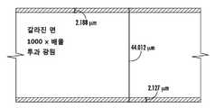
도 1에 도시된 적층 구조를 가지며 0.7mm의 두께를 가진 3개의 층 유리 프리폼이 융합 인발 공정을 이용하여 형성되었다. 코어 층은 약 620㎛ 두께를 가지며, 제1 및 제2 클래딩 층 각각은 약 40㎛의 두께를 갖는다. 따라서, 코어 층의 프리폼 두께 비는 약 0.9이다. 유리 프리폼은 44㎛ 두께의 인발된 유리 시트를 형성하기 위해 인발된다. 도 8은 인발된 유리 시트의 단면을 나타낸다. 코어 층은 약 40㎛의 두께를 가지며, 각각의 제1 및 제2 클래딩 층은 약 2㎛의 두께를 갖는다. 따라서, 코어 층의 시트 두께 비는 약 0.9이다.Three layered glass preforms having the lamination structure shown in Fig. 1 and having a thickness of 0.7 mm were formed using a fusion drawing process. The core layer has a thickness of about 620 占 퐉, and each of the first and second cladding layers has a thickness of about 40 占 퐉. Thus, the preform thickness ratio of the core layer is about 0.9. The glass preform is drawn to form a 44 탆 thick drawn glass sheet. 8 shows a section of the drawn glass sheet. The core layer has a thickness of about 40 占 퐉, and each of the first and second cladding layers has a thickness of about 2 占 퐉. Therefore, the sheet thickness ratio of the core layer is about 0.9.
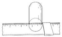
도 9는 인발된 유리 시트가 반경으로 구부러진 것을 나타낸다. 인발된 유리 시트는 26mm의 이론상 최소 굽힘 반경에 비교하여, 약 31mm의 반경으로 구부러질 수 있다.Figure 9 shows that the drawn glass sheet is curved to a radius. The drawn glass sheet can be bent to a radius of about 31 mm, compared to a theoretical minimum bending radius of 26 mm.
본 발명의 사상 및 범위를 벗어나지 않고 다양한 수정 및 변형이 이루어질 수 있음은 당업자에게 명백할 것이다. 따라서, 본 발명은 첨부된 청구 범위 및 그 등가물의 관점을 제외하고는 제한되지 않는다.It will be apparent to those skilled in the art that various modifications and variations can be made without departing from the spirit and scope of the invention. Accordingly, the invention is not limited except as by the appended claims and equivalents thereof.
Claims (37)
Translated fromKorean상기 유리 프리폼으로부터 말단으로 연장되며 다수의 유리 층으로 구성되는 인발된 유리 시트(glass sheet)를 형성하기 위해 말단 방향으로 유리 프리폼을 인발하는 단계로서, 상기 인발된 유리 시트의 두께가 상기 유리 프리폼의 두께보다 작으며; 및
상기 인발된 유리 시트를 수집 스풀(spool)에 감는 단계로 구성된 방법.Heating a glass preform comprised of a plurality of glass layers;
Drawing a glass preform in a distal direction to form a drawn glass sheet extending from the glass preform to an end and comprising a plurality of glass layers, the thickness of the drawn glass sheet being greater than the thickness of the glass preform Less than the thickness; And
And winding the drawn glass sheet onto a collection spool.
상기 유리 프리폼은 다수의 유리 층으로 구성된 하나의 적층 구조로 이루어진, 방법.The method according to claim 1,
Wherein the glass preform comprises a single laminate structure comprising a plurality of glass layers.
상기 다수의 유리 층의 각각의 프리폼 두께 비는 유리 프리폼의 두께에 대한 유리 프리폼의 각각의 유리 층의 두께의 비를 포함하며;
상기 다수의 유리 층의 각각의 시트 두께 비는 인발된 유리 시트의 두께에 대한 인발된 유리 시트의 각각의 유리 층의 두께의 비를 포함하고;
상기 유리 층의 각각의 프리폼 두께 비는 각각의 유리 층의 시트 두께 비와 실질적으로 같은, 방법.The method according to claim 1 or 2,
Wherein each preform thickness ratio of the plurality of glass layers comprises a ratio of the thickness of each glass layer of the glass preform to a thickness of the glass preform;
Wherein each sheet thickness ratio of the plurality of glass layers comprises a ratio of the thickness of each glass layer of the drawn glass sheet to a thickness of the drawn glass sheet;
Wherein each preform thickness ratio of the glass layer is substantially equal to a sheet thickness ratio of each glass layer.
상기 유리 프리폼을 형성하기 위해 점성 상태의 제1 유리 층의 제1 유리 조성물과 점성 상태의 제2 유리 층의 제2 유리 조성물을 접촉시키는 단계를 추가로 포함하는, 방법.4. The method according to any one of claims 1 to 3,
Further comprising contacting the first glass composition of the first glass layer in the viscous state with the second glass composition of the second glass layer in the viscous state to form the glass preform.
상기 접촉 단계는 융합 인발 장치에서 제1 유리 조성물과 제2 유리 조성물을 접촉시키는 단계를 포함하는, 방법.The method of claim 4,
Wherein the contacting step comprises contacting the first glass composition and the second glass composition in a fusion drawing apparatus.
상기 다수의 유리 층은 제1 유리 층 및 상기 제1 유리 층에 인접한 제2 유리 층을 구비하며, 인발된 유리 시트로부터 제2 유리 층의 적어도 일부분을 제거하는 단계를 포함하는, 방법.The method according to any one of claims 1 to 5,
Wherein the plurality of glass layers comprises a first glass layer and a second glass layer adjacent the first glass layer and removing at least a portion of the second glass layer from the drawn glass sheet.
시약에서의 상기 제2 유리 층의 분해 속도는 시약의 제1 유리 층의 분해 속도보다 크며, 상기 제거하는 단계는 인발된 유리 시트를 시약과 접촉시키는 단계를 포함하는, 방법.The method of claim 6,
Wherein the rate of decomposition of the second glass layer in the reagent is greater than the rate of decomposition of the first glass layer of the reagent and the removing comprises contacting the drawn glass sheet with a reagent.
상기 제1 유리 층은 코어 층(core layer)으로 이루어지고, 상기 제2 유리 층은 제1 클래딩 층(cladding layer) 및 제2 클래딩 층으로 이루어지며, 상기 코어 층은 상기 제1 클래딩 층과 제2 클래딩 층 사이에 배치되는, 방법.The method according to claim 6 or 7,
Wherein the first glass layer comprises a core layer, the second glass layer comprises a first cladding layer and a second cladding layer, and the core layer comprises a first cladding layer and a second cladding layer, 2 cladding layer.
사익 코어 층의 시트 두께 비는 상기 제거 단계 전에 인발된 유리 시트의 두께에 대한 인발된 유리 시트에서의 코어 층의 두께의 비를 포함하며, 코어 층의 시트 두께 비는 최대 약 0.8인, 방법.The method of claim 8,
Wherein the sheet thickness ratio of the sacrificial core layer comprises the ratio of the thickness of the core layer in the drawn glass sheet to the thickness of the drawn glass sheet prior to the removing step and wherein the sheet thickness ratio of the core layer is at most about 0.8.
상기 유리 프리폼의 두께는 적어도 약 100㎛이며, 인발된 유리 시트의 제1 층의 두께는 약 50㎛보다 작은, 방법.The method according to any one of claims 6 to 9,
Wherein the thickness of the glass preform is at least about 100 占 퐉 and the thickness of the first layer of drawn glass sheet is less than about 50 占 퐉.
상기 제거 단계 이전에 제1 유리 층의 표면에 전자 장치를 형성하는 단계를 추가로 포함하는, 방법.The method according to any one of claims 6 to 9,
Further comprising forming an electronic device on a surface of the first glass layer prior to the removing step.
상기 전자 장치는 박막 트랜지스터(TFT, thin film transistor)를 포함하는, 방법.The method of claim 11,
Wherein the electronic device comprises a thin film transistor (TFT).
상기 다수의 유리 층은 제1 클래딩 층과 제2 클래딩 층 사이에 배치된 코어 층으로 이루어지며, 상기 제1 클래딩 층과 제2 클래딩 층을 서로 분리하기 위해 인발된 유리 시트로부터 코어 층의 적어도 일부분을 제거하는 단계를 포함하는, 방법.The method according to any one of claims 1 to 5,
Wherein the plurality of glass layers comprises a core layer disposed between the first cladding layer and the second cladding layer and at least a portion of the core layer from the drawn glass sheet to separate the first cladding layer and the second cladding layer from each other / RTI >
상기 제거 단계 이전에 상기 제1 클래딩 층 또는 제2 클래딩 층 중 적어도 하나의 표면에 전자 장치를 형성하는 단계를 추가로 포함하는, 방법.The method of claim 13,
Further comprising forming an electronic device on a surface of at least one of the first cladding layer or the second cladding layer prior to the removing step.
상기 다수의 유리 층은 제1 클래딩 층과 제2 클래딩 층 사이에 배치된 코어 층으로 이루어진, 방법.The method according to any one of claims 1 to 5,
Wherein the plurality of glass layers comprise a core layer disposed between the first cladding layer and the second cladding layer.
상기 코어 층의 평균 열팽창계수(CTE)는 상기 제1 클래딩 층과 제2 클래딩 층 각각의 평균 CTE보다 큰, 방법.16. The method of claim 15,
Wherein an average CTE of the core layer is greater than an average CTE of each of the first and second cladding layers.
상기 제1 클래딩 층 및 제2 클래딩 층 각각과의 이온 교환을 통해 코어 층을 화학적으로 강화하는 단계를 추가로 포함하는, 방법.16. The method according to claim 15 or 16,
Further comprising chemically enhancing the core layer through ion exchange with each of the first cladding layer and the second cladding layer.
상기 인발 단계 및 화학적 강화 단계 다음으로 상기 강화된 코어 층으로부터 제1 및 제2 클래딩 층을 제거하는 단계를 추가로 포함하는, 방법.18. The method of claim 17,
Further comprising removing the first and second cladding layers from the reinforced core layer following the drawing step and the chemical strengthening step.
상기 유리 프리폼으로부터 말단으로 연장되며 제1 유리 층 및 제2 유리 층으로 구성되는 인발된 유리 시트를 형성하기 위해 말단 방향으로 유리 프리폼을 인발하는 단계로서, 상기 인발된 유리 시트의 두께가 상기 유리 프리폼의 두께보다 작으며; 및
상기 인발된 유리 시트로부터 제2 유리 층의 적어도 일부분을 제거하는 단계로 이루어진 방법.Heating a glass preform comprising a first glass layer and a second glass layer adjacent to the first glass layer;
Drawing a glass preform in a distal direction to form a drawn glass sheet extending from the glass preform to the end and consisting of a first glass layer and a second glass layer, the thickness of the drawn glass sheet being greater than the thickness of the glass preform Lt; / RTI > And
And removing at least a portion of the second glass layer from the drawn glass sheet.
시약에서의 상기 제2 유리 층의 분해 속도는 시약에서의 제2 유리 층의 분해 속도보다 크며, 상기 제거 단계는 상기 인발된 유리 시트를 시약과 접촉시키는 단계를 포함하는, 방법.The method of claim 19,
Wherein the rate of decomposition of the second glass layer in the reagent is greater than the rate of decomposition of the second glass layer in the reagent, and wherein the removing comprises contacting the withdrawn glass sheet with a reagent.
상기 제거 단계 이전에 제1 유리 층의 표면에 전자 장치를 형성하는 단계를 추가로 포함하는, 방법.The method of claim 19 or 20,
Further comprising forming an electronic device on a surface of the first glass layer prior to the removing step.
상기 제2 유리 층은 제1 클래딩 층 및 제2 클래딩 층으로 이루어지며, 상기 제1 유리 층은 상기 제1 클래딩 층과 제2 클래딩 층 사이에 배치된 코어 층을 포함하는, 방법.21. A method according to any one of claims 19 to 21,
Wherein the second glass layer comprises a first cladding layer and a second cladding layer and the first glass layer comprises a core layer disposed between the first cladding layer and the second cladding layer.
상기 제1 유리 층은 제1 클래딩 층 및 제2 클래딩 층으로 이루어지며, 상기 제2 유리 층은 상기 제1 클래딩 층과 제2 클래딩 층 사이에 배치된 코어 층을 포함하는, 방법.21. A method according to any one of claims 19 to 21,
Wherein the first glass layer comprises a first cladding layer and a second cladding layer and the second glass layer comprises a core layer disposed between the first cladding layer and the second cladding layer.
상기 인발 단계는 상기 유리 프리폼을 가열 유닛으로 공급 속도로 도입하고 인발된 유리 시트를 가열 유닛으로부터, 상기 공급 속도보다 더 빠른 인발 속도로 빼내는 단계를 포함하는, 방법.23. The method according to any one of claims 19 to 23,
Wherein the drawing step comprises introducing the glass preform into a heating unit at a feed rate and withdrawing the drawn glass sheet from the heating unit at a draw rate that is faster than the feed rate.
상기 인발된 유리 시트를 수집 스풀에 감는 단계를 추가로 포함하는, 방법.The method according to any one of claims 19 to 24,
Further comprising winding the pulled-out glass sheet onto a collection spool.
상기 유리 프리폼에서 말단으로 연장되는 인발된 유리 시트를 형성하기 위해 말단 방향으로 유리 프리폼을 인발하도록 구성된 인발 유닛; 및
수집 스풀에 상기 인발된 유리 시트를 감도록 구성된 수집 유닛으로 구성되며,
상기 인발된 유리 시트는 다수의 유리 층으로 구성되고, 상기 인발된 유리 시트의 두께는 유리 프리폼의 두께보다 작은, 시스템.A heating unit configured to heat a glass preform composed of a plurality of glass layers;
A drawing unit configured to draw a glass preform in an end direction to form a drawn glass sheet extending from the glass preform to an end; And
And a collection unit configured to wind the pulled-out glass sheet to a collection spool,
Wherein the drawn glass sheet is comprised of a plurality of glass layers and wherein the thickness of the drawn glass sheet is less than the thickness of the glass preform.
폴리싱되지 않은 외부 표면을 추가로 포함하는, 유리 시트.28. The method of claim 27,
Further comprising a non-polished outer surface.
시약에서의 제2 유리 층의 분해 속도는 시약에서의 제1 유리 층의 분해 속도보다 크며, 시약과 유리 시트를 접촉시키는 것은 상기 제2 유리 층의 적어도 일부분을 제거하는, 유리 시트.28. The method of claim 27 or 28,
Wherein the rate of decomposition of the second glass layer in the reagent is greater than the rate of decomposition of the first glass layer in the reagent and contacting the reagent with the glass sheet removes at least a portion of the second glass layer.
상기 제2 유리 층은 제1 클래딩 층과 제2 클래딩 층으로 이루어지며, 제1 유리 층은 제1 클래딩 층과 제2 클래딩 층 사이에 배치된 코어 층으로 이루어지는, 유리 시트.29. The method of any one of claims 27-29,
Wherein the second glass layer comprises a first cladding layer and a second cladding layer, and the first glass layer comprises a core layer disposed between the first cladding layer and the second cladding layer.
상기 각각의 제1 클래딩 층과 제2 클래딩 층은 코어 층의 평균 열팽창계수(CTE)보다 작은 평균 CTE를 갖는, 유리 시트.32. The method of claim 30,
Wherein each of the first cladding layer and the second cladding layer has an average CTE that is less than an average thermal expansion coefficient (CTE) of the core layer.
유리 시트의 표면에 형성된 전자 장치를 추가로 포함하는, 유리 시트.31. The method according to any one of claims 27 to 31,
Further comprising an electronic device formed on the surface of the glass sheet.
이론상 최소 굽힘 반경의 약 40% 내의 굽힘 반경으로 구부러질 수 있는, 유리 시트.29. The method of any one of claims 27-32,
The glass sheet being theoretically capable of bending with a bending radius within about 40% of the minimum bending radius.
약 50mm보다 작거나 같은 굽힘 반경으로 굽혀질 수 있는, 유리 시트.33. The method according to any one of claims 27 to 33,
Wherein the glass sheet can be bent at a bending radius less than or equal to about 50 mm.
수집 스풀로 감겨지는 이온 교환 유리 시트.36. The method of claim 35,
Ion exchange glass sheet wound with a collection spool.
Applications Claiming Priority (3)
| Application Number | Priority Date | Filing Date | Title |
|---|---|---|---|
| US201462084826P | 2014-11-26 | 2014-11-26 | |
| US62/084,826 | 2014-11-26 | ||
| PCT/US2015/061724WO2016085778A1 (en) | 2014-11-26 | 2015-11-20 | Thin glass sheet and system and method for forming the same |
Publications (1)
| Publication Number | Publication Date |
|---|---|
| KR20170088953Atrue KR20170088953A (en) | 2017-08-02 |
Family
ID=54780469
Family Applications (1)
| Application Number | Title | Priority Date | Filing Date |
|---|---|---|---|
| KR1020177017459AAbandonedKR20170088953A (en) | 2014-11-26 | 2015-11-20 | Thin glass sheet and system and method for forming the same |
Country Status (7)
| Country | Link |
|---|---|
| US (2) | US11078102B2 (en) |
| EP (2) | EP3224209B1 (en) |
| JP (1) | JP2018500263A (en) |
| KR (1) | KR20170088953A (en) |
| CN (1) | CN107207309B (en) |
| TW (1) | TWI675013B (en) |
| WO (1) | WO2016085778A1 (en) |
Families Citing this family (19)
| Publication number | Priority date | Publication date | Assignee | Title |
|---|---|---|---|---|
| TWI707829B (en)* | 2015-11-20 | 2020-10-21 | 美商康寧公司 | Laminated glass ribbons and apparatuses for forming laminated glass ribbons |
| EP3548277B1 (en)* | 2016-11-30 | 2023-10-25 | Corning Incorporated | Fusion-formable automotive glass compositions, articles, and laminates |
| DE102018111543A1 (en)* | 2017-05-22 | 2018-11-22 | Schott Ag | Method and device for thickness control of a material band |
| US11584673B2 (en)* | 2017-07-31 | 2023-02-21 | Corning Incorporated | Laminate article having a non-glass core and glass envelope and methods thereof |
| JP7011062B2 (en) | 2017-10-27 | 2022-01-26 | ショット アクチエンゲゼルシャフト | Equipment and methods for manufacturing flat glass |
| WO2019105604A1 (en)* | 2017-11-30 | 2019-06-06 | Lisec Austria Gmbh | Device for dividing material panels |
| CN108249743B (en)* | 2018-03-28 | 2021-02-23 | 河北省沙河玻璃技术研究院 | Shaping method suitable for drawing flexible glass |
| US20210291494A1 (en)* | 2018-07-17 | 2021-09-23 | Corning Incorporated | Redrawn glass having enhanced puncture resistance |
| CN113056442A (en)* | 2018-11-21 | 2021-06-29 | 肖特股份有限公司 | Method and apparatus for manufacturing thin glass and thin glass ribbon |
| WO2020129907A1 (en)* | 2018-12-21 | 2020-06-25 | 日本電気硝子株式会社 | Manufacturing method for glass plate and manufacturing device for same |
| WO2020180515A1 (en)* | 2019-03-07 | 2020-09-10 | Corning Incorporated | Glass carrier for die-up fan-out packaging and methods for making the same |
| EP3938205A1 (en)* | 2019-03-11 | 2022-01-19 | Corning Incorporated | Damage resistant glass laminate and methods of making the same |
| CN113784933B (en) | 2019-03-29 | 2023-10-20 | 康宁公司 | Scratch-resistant and mar-resistant laminated glass article |
| KR20210154825A (en)* | 2019-04-23 | 2021-12-21 | 코닝 인코포레이티드 | Glass laminate with definite stress profile and method for manufacturing the same |
| CN110563323B (en)* | 2019-10-22 | 2022-03-01 | 河北省沙河玻璃技术研究院 | Platinum-rhodium alloy bushing plate for drawing high-quality flexible glass |
| CN115734947A (en)* | 2020-06-19 | 2023-03-03 | 康宁公司 | Method of making a glass ribbon |
| JP2024500106A (en)* | 2020-12-18 | 2024-01-04 | コーニング インコーポレイテッド | Manufacturing method of glass plate that reduces overall thickness variation |
| CN112661418B (en)* | 2020-12-24 | 2023-01-20 | 江西沃格光电股份有限公司 | UTG product tempering jig and method thereof |
| CN115417583B (en)* | 2022-09-05 | 2024-02-27 | 河北光兴半导体技术有限公司 | Method for producing foldable glass and foldable glass |
Family Cites Families (61)
| Publication number | Priority date | Publication date | Assignee | Title |
|---|---|---|---|---|
| US3582305A (en)* | 1968-06-03 | 1971-06-01 | Owens Illinois Inc | Method and apparatus for the manufacture of a contoured redrawn glass article |
| US3684468A (en)* | 1969-04-28 | 1972-08-15 | Owens Illinois Inc | Fabrication of planar capillary tube structure for gas discharge panel |
| US3635687A (en)* | 1970-05-26 | 1972-01-18 | Owens Illinois Inc | Downdrawing method for producing very thin glass sheets |
| US3746526A (en) | 1971-03-10 | 1973-07-17 | Corning Glass Works | Method for forming subsurface fortified laminates |
| US3879182A (en)* | 1974-02-04 | 1975-04-22 | American Optical Corp | Method of making minature prisms |
| US3899315A (en)* | 1974-04-15 | 1975-08-12 | American Optical Corp | Method of making glass clad glass lenses |
| US4102664A (en)* | 1977-05-18 | 1978-07-25 | Corning Glass Works | Method for making glass articles with defect-free surfaces |
| US4214886A (en) | 1979-04-05 | 1980-07-29 | Corning Glass Works | Forming laminated sheet glass |
| CH642933A5 (en)* | 1979-10-22 | 1984-05-15 | Micafil Ag | METHOD AND DEVICE FOR PRODUCING A GLASS FILM. |
| US4268296A (en)* | 1979-12-03 | 1981-05-19 | Owens-Illinois, Inc. | Method and apparatus for manufacture of glass film |
| JPS5895622A (en)* | 1981-12-01 | 1983-06-07 | Nippon Electric Glass Co Ltd | Manufacture of thin glass plate |
| US4486213A (en)* | 1982-09-29 | 1984-12-04 | Corning Glass Works | Drawing laminated polarizing glasses |
| US5100452A (en)* | 1990-05-17 | 1992-03-31 | Corning Incorporated | Making glass articles with defect-free surfaces |
| US5342426A (en)* | 1993-07-16 | 1994-08-30 | Corning Incorporated | Making glass sheet with defect-free surfaces and alkali metal-free soluble glasses therefor |
| EP0719741B1 (en)* | 1994-12-27 | 1998-05-27 | Hoya Corporation | Process for the production of polarizing glass |
| DE69502007T2 (en)* | 1994-12-27 | 1998-11-12 | Hoya Corp | Polarizing glass and process for its manufacture |
| US6912087B1 (en)* | 1998-05-14 | 2005-06-28 | Corning Incorporated | Ultra-thin glass polarizers and method of making same |
| DE19848083C2 (en)* | 1998-10-19 | 2001-02-01 | Fraunhofer Ges Forschung | Process for the production of interference layer sequences, system of superimposed interference layer sequences as well as interference layer sequences |
| JP2000203857A (en)* | 1999-01-08 | 2000-07-25 | Nippon Sheet Glass Co Ltd | Production of glass spacer |
| US20040093900A1 (en)* | 2002-11-15 | 2004-05-20 | Fredholm Allan M. | Apparatus and method for producing sheets of glass presenting at least one face of very high surface quality |
| US7514149B2 (en) | 2003-04-04 | 2009-04-07 | Corning Incorporated | High-strength laminated sheet for optical applications |
| US20050000599A1 (en)* | 2003-07-03 | 2005-01-06 | Liebermann Howard H. | Amorphous and nanocrystalline glass-coated articles |
| US7231786B2 (en)* | 2004-07-29 | 2007-06-19 | Corning Incorporated | Process and device for manufacturing glass sheet |
| US7201965B2 (en)* | 2004-12-13 | 2007-04-10 | Corning Incorporated | Glass laminate substrate having enhanced impact and static loading resistance |
| EP1710212A1 (en) | 2005-04-06 | 2006-10-11 | Corning Incorporated | process and device for manufacturing flat sheets of a glass-based material |
| JP4865298B2 (en)* | 2005-11-01 | 2012-02-01 | 古河電気工業株式会社 | Manufacturing method of glass strip |
| US8017220B2 (en)* | 2006-10-04 | 2011-09-13 | Corning Incorporated | Electronic device and method of making |
| US7677058B2 (en) | 2007-05-07 | 2010-03-16 | Corning Incorporated | Process and apparatus for making glass sheet |
| WO2008150355A1 (en) | 2007-05-21 | 2008-12-11 | Corning Incorporated | Thermally-bonded glass-ceramic/glass laminates, their use in armor applications and methods of making same |
| KR101451197B1 (en) | 2007-06-07 | 2014-10-15 | 니폰 덴키 가라스 가부시키가이샤 | Hardened glass substrate, and method for production thereof |
| EP2204355A4 (en)* | 2007-10-30 | 2012-10-31 | Asahi Glass Co Ltd | METHOD FOR PRODUCING A GLASS / RESIN COMPOSITE |
| EP2065345A1 (en)* | 2007-11-29 | 2009-06-03 | Corning Incorporated | Apparatus and method for producing sheets of glass presenting at least one face of very high surface quality |
| US8359884B2 (en) | 2009-07-17 | 2013-01-29 | Corning Incorporated | Roll-to-roll glass: touch-free process and multilayer approach |
| CN102448900B (en)* | 2009-07-30 | 2015-05-27 | 日本电气硝子株式会社 | Glass ribbon and process for production thereof |
| JP5652742B2 (en)* | 2010-02-12 | 2015-01-14 | 日本電気硝子株式会社 | Tempered plate glass and manufacturing method thereof |
| JP5644129B2 (en) | 2010-02-12 | 2014-12-24 | 日本電気硝子株式会社 | Tempered plate glass and manufacturing method thereof |
| JP5704395B2 (en)* | 2010-03-29 | 2015-04-22 | 日本電気硝子株式会社 | Glass roll package |
| US8778820B2 (en)* | 2010-05-27 | 2014-07-15 | Corning Incorporated | Glasses having low softening temperatures and high toughness |
| JP5844361B2 (en)* | 2010-06-29 | 2016-01-13 | コーニング インコーポレイテッド | Multi-layer glass plate manufactured by co-stretching using overflow, downdraw and fusion methods |
| US9333724B2 (en)* | 2010-07-28 | 2016-05-10 | Nippon Electric Glass Co., Ltd. | Glass film laminate |
| JP5614231B2 (en) | 2010-10-20 | 2014-10-29 | 日本電気硝子株式会社 | Manufacturing method of glass film |
| CN103261107B (en)* | 2010-12-14 | 2015-11-25 | 旭硝子株式会社 | The manufacture method of glass-pane shaping product and the manufacturing installation of glass-pane shaping product |
| US9034458B2 (en)* | 2011-05-27 | 2015-05-19 | Corning Incorporated | Edge-protected product and finishing method |
| CN104185611B (en)* | 2011-11-09 | 2018-02-06 | 康宁股份有限公司 | The method and apparatus for manufacturing glass tape |
| TW201402492A (en) | 2012-07-09 | 2014-01-16 | Global Display Co Ltd | Method for manufacturing ultra-thin glass |
| US20140050911A1 (en) | 2012-08-17 | 2014-02-20 | Corning Incorporated | Ultra-thin strengthened glasses |
| US10160684B2 (en) | 2013-02-24 | 2018-12-25 | Flex Optronix Technologies, LLC | Method of co-drawing hybrid incompatible materials |
| US9393760B2 (en)* | 2013-02-28 | 2016-07-19 | Corning Incorporated | Laminated glass articles with phase-separated claddings and methods for forming the same |
| KR101825276B1 (en) | 2013-03-15 | 2018-02-02 | 쇼오트 글라스 테크놀로지스 (쑤저우) 코퍼레이션 리미티드. | Chemically toughened flexible ultrathin glass |
| DE102014100750B4 (en)* | 2013-04-30 | 2023-08-17 | Schott Ag | Process for the manufacture of glass components |
| DE102013109443B4 (en)* | 2013-08-30 | 2017-06-22 | Schott Ag | Process for drawing glass ribbons |
| CN103474580A (en) | 2013-09-09 | 2013-12-25 | 京东方科技集团股份有限公司 | Flexible organic electroluminescence device packaging structure, method and flexible displaying device |
| US9321677B2 (en) | 2014-01-29 | 2016-04-26 | Corning Incorporated | Bendable glass stack assemblies, articles and methods of making the same |
| US20150251944A1 (en)* | 2014-03-10 | 2015-09-10 | Corning Incorporated | Methods and apparatuses for separating glass ribbons |
| DE102014103431B4 (en)* | 2014-03-13 | 2015-10-01 | Schott Ag | Method and apparatus for reducing the saberiness of thin glasses and thereafter produced thin glass band |
| JP6679585B2 (en)* | 2014-10-07 | 2020-04-15 | ショット アクチエンゲゼルシャフトSchott AG | Laminated glass with increased strength |
| DE102015118308B4 (en)* | 2014-10-29 | 2023-07-27 | Schott Ag | Method for producing a ceramizable green glass component and ceramizable green glass component and glass ceramic article |
| DE102017101808B4 (en)* | 2016-02-04 | 2024-12-24 | Schott Ag | Method for checking the thickness of a substrate |
| DE102016107934B4 (en)* | 2016-04-28 | 2023-07-13 | Schott Ag | Process for the production of high-index thin glass substrates |
| DE102016115297A1 (en)* | 2016-08-17 | 2018-02-22 | Schott Ag | Thin glass product and process for its production |
| JP2024095622A (en) | 2022-12-28 | 2024-07-10 | 株式会社希松 | Emulsion particle refining agent, emulsion stability improver, method for improving emulsion stability of emulsion, method for producing emulsion, and emulsion |
- 2015
- 2015-11-20KRKR1020177017459Apatent/KR20170088953A/ennot_activeAbandoned
- 2015-11-20CNCN201580074482.8Apatent/CN107207309B/enactiveActive
- 2015-11-20JPJP2017528168Apatent/JP2018500263A/enactivePending
- 2015-11-20USUS15/529,226patent/US11078102B2/enactiveActive
- 2015-11-20EPEP15804657.3Apatent/EP3224209B1/ennot_activeNot-in-force
- 2015-11-20EPEP21202893.0Apatent/EP3978450A1/ennot_activeWithdrawn
- 2015-11-20WOPCT/US2015/061724patent/WO2016085778A1/enactiveApplication Filing
- 2015-11-26TWTW104139457Apatent/TWI675013B/ennot_activeIP Right Cessation
- 2021
- 2021-06-24USUS17/357,321patent/US12291474B2/enactiveActive
Also Published As
| Publication number | Publication date |
|---|---|
| US20180327296A1 (en) | 2018-11-15 |
| TW201627239A (en) | 2016-08-01 |
| CN107207309A (en) | 2017-09-26 |
| CN107207309B (en) | 2020-08-18 |
| WO2016085778A1 (en) | 2016-06-02 |
| US12291474B2 (en) | 2025-05-06 |
| EP3224209B1 (en) | 2021-12-15 |
| JP2018500263A (en) | 2018-01-11 |
| US11078102B2 (en) | 2021-08-03 |
| US20210317028A1 (en) | 2021-10-14 |
| TWI675013B (en) | 2019-10-21 |
| EP3224209A1 (en) | 2017-10-04 |
| EP3978450A1 (en) | 2022-04-06 |
Similar Documents
| Publication | Publication Date | Title |
|---|---|---|
| KR20170088953A (en) | Thin glass sheet and system and method for forming the same | |
| JP6149300B2 (en) | Apparatus and method for characterizing glass sheets | |
| CN102471128B (en) | Method for manufacturing ultra-thin glass substrate | |
| TWI576295B (en) | Fabricating method of glass roll and glass roll | |
| JP5343862B2 (en) | Method for producing glass resin composite | |
| JP4982366B2 (en) | Glass sheet manufacturing method and manufacturing apparatus | |
| JP5949894B2 (en) | GLASS LAMINATE, ITS MANUFACTURING METHOD, DISPLAY PANEL MANUFACTURING METHOD, AND DISPLAY PANEL OBTAINED BY THE MANUFACTURING METHOD | |
| JP2014166944A (en) | Method of producing glass film | |
| CN105722676B (en) | Glass film laminate and method for manufacturing liquid crystal panel | |
| WO2017007868A1 (en) | Apparatuses and methods for heating moving glass ribbons at separation lines and/or for separating glass sheets from glass ribbons | |
| US10246374B2 (en) | Method for manufacturing glass film laminate, glass film laminate, and method for manufacturing electronic device | |
| JP2010215436A (en) | Glass film laminate | |
| CN111902381B (en) | Glass substrate adhesion control | |
| JP6454188B2 (en) | Manufacturing method of glass substrate | |
| WO2014178404A1 (en) | Glass film laminate, and production method for electronic device | |
| JP2013166570A (en) | Thin wall glass plate laminate, separation method thereof, and thin wall glass plate |
Legal Events
| Date | Code | Title | Description |
|---|---|---|---|
| PA0105 | International application | St.27 status event code:A-0-1-A10-A15-nap-PA0105 | |
| P11-X000 | Amendment of application requested | St.27 status event code:A-2-2-P10-P11-nap-X000 | |
| P13-X000 | Application amended | St.27 status event code:A-2-2-P10-P13-nap-X000 | |
| R15-X000 | Change to inventor requested | St.27 status event code:A-3-3-R10-R15-oth-X000 | |
| R16-X000 | Change to inventor recorded | St.27 status event code:A-3-3-R10-R16-oth-X000 | |
| PG1501 | Laying open of application | St.27 status event code:A-1-1-Q10-Q12-nap-PG1501 | |
| E13-X000 | Pre-grant limitation requested | St.27 status event code:A-2-3-E10-E13-lim-X000 | |
| P11-X000 | Amendment of application requested | St.27 status event code:A-2-2-P10-P11-nap-X000 | |
| P13-X000 | Application amended | St.27 status event code:A-2-2-P10-P13-nap-X000 | |
| PA0201 | Request for examination | St.27 status event code:A-1-2-D10-D11-exm-PA0201 | |
| E902 | Notification of reason for refusal | ||
| PE0902 | Notice of grounds for rejection | St.27 status event code:A-1-2-D10-D21-exm-PE0902 | |
| T11-X000 | Administrative time limit extension requested | St.27 status event code:U-3-3-T10-T11-oth-X000 | |
| R17-X000 | Change to representative recorded | St.27 status event code:A-3-3-R10-R17-oth-X000 | |
| T11-X000 | Administrative time limit extension requested | St.27 status event code:U-3-3-T10-T11-oth-X000 | |
| T11-X000 | Administrative time limit extension requested | St.27 status event code:U-3-3-T10-T11-oth-X000 | |
| T11-X000 | Administrative time limit extension requested | St.27 status event code:U-3-3-T10-T11-oth-X000 | |
| P11-X000 | Amendment of application requested | St.27 status event code:A-2-2-P10-P11-nap-X000 | |
| P13-X000 | Application amended | St.27 status event code:A-2-2-P10-P13-nap-X000 | |
| E90F | Notification of reason for final refusal | ||
| PE0902 | Notice of grounds for rejection | St.27 status event code:A-1-2-D10-D21-exm-PE0902 | |
| T11-X000 | Administrative time limit extension requested | St.27 status event code:U-3-3-T10-T11-oth-X000 | |
| T11-X000 | Administrative time limit extension requested | St.27 status event code:U-3-3-T10-T11-oth-X000 | |
| T11-X000 | Administrative time limit extension requested | St.27 status event code:U-3-3-T10-T11-oth-X000 | |
| P11-X000 | Amendment of application requested | St.27 status event code:A-2-2-P10-P11-nap-X000 | |
| P13-X000 | Application amended | St.27 status event code:A-2-2-P10-P13-nap-X000 | |
| E701 | Decision to grant or registration of patent right | ||
| PE0701 | Decision of registration | St.27 status event code:A-1-2-D10-D22-exm-PE0701 | |
| PC1904 | Unpaid initial registration fee | St.27 status event code:A-2-2-U10-U14-oth-PC1904 St.27 status event code:N-2-6-B10-B12-nap-PC1904 |