KR20170079244A - Liquid crystal dispaly device - Google Patents
Liquid crystal dispaly deviceDownload PDFInfo
- Publication number
- KR20170079244A KR20170079244AKR1020150189601AKR20150189601AKR20170079244AKR 20170079244 AKR20170079244 AKR 20170079244AKR 1020150189601 AKR1020150189601 AKR 1020150189601AKR 20150189601 AKR20150189601 AKR 20150189601AKR 20170079244 AKR20170079244 AKR 20170079244A
- Authority
- KR
- South Korea
- Prior art keywords
- liquid crystal
- panel
- guide
- guide panel
- crystal panel
- Prior art date
- Legal status (The legal status is an assumption and is not a legal conclusion. Google has not performed a legal analysis and makes no representation as to the accuracy of the status listed.)
- Withdrawn
Links
Images


Classifications
- G—PHYSICS
- G02—OPTICS
- G02F—OPTICAL DEVICES OR ARRANGEMENTS FOR THE CONTROL OF LIGHT BY MODIFICATION OF THE OPTICAL PROPERTIES OF THE MEDIA OF THE ELEMENTS INVOLVED THEREIN; NON-LINEAR OPTICS; FREQUENCY-CHANGING OF LIGHT; OPTICAL LOGIC ELEMENTS; OPTICAL ANALOGUE/DIGITAL CONVERTERS
- G02F1/00—Devices or arrangements for the control of the intensity, colour, phase, polarisation or direction of light arriving from an independent light source, e.g. switching, gating or modulating; Non-linear optics
- G02F1/01—Devices or arrangements for the control of the intensity, colour, phase, polarisation or direction of light arriving from an independent light source, e.g. switching, gating or modulating; Non-linear optics for the control of the intensity, phase, polarisation or colour
- G02F1/13—Devices or arrangements for the control of the intensity, colour, phase, polarisation or direction of light arriving from an independent light source, e.g. switching, gating or modulating; Non-linear optics for the control of the intensity, phase, polarisation or colour based on liquid crystals, e.g. single liquid crystal display cells
- G02F1/133—Constructional arrangements; Operation of liquid crystal cells; Circuit arrangements
- G02F1/1333—Constructional arrangements; Manufacturing methods
- G02F1/133308—Support structures for LCD panels, e.g. frames or bezels
- G—PHYSICS
- G02—OPTICS
- G02F—OPTICAL DEVICES OR ARRANGEMENTS FOR THE CONTROL OF LIGHT BY MODIFICATION OF THE OPTICAL PROPERTIES OF THE MEDIA OF THE ELEMENTS INVOLVED THEREIN; NON-LINEAR OPTICS; FREQUENCY-CHANGING OF LIGHT; OPTICAL LOGIC ELEMENTS; OPTICAL ANALOGUE/DIGITAL CONVERTERS
- G02F1/00—Devices or arrangements for the control of the intensity, colour, phase, polarisation or direction of light arriving from an independent light source, e.g. switching, gating or modulating; Non-linear optics
- G02F1/01—Devices or arrangements for the control of the intensity, colour, phase, polarisation or direction of light arriving from an independent light source, e.g. switching, gating or modulating; Non-linear optics for the control of the intensity, phase, polarisation or colour
- G02F1/13—Devices or arrangements for the control of the intensity, colour, phase, polarisation or direction of light arriving from an independent light source, e.g. switching, gating or modulating; Non-linear optics for the control of the intensity, phase, polarisation or colour based on liquid crystals, e.g. single liquid crystal display cells
- G02F1/133—Constructional arrangements; Operation of liquid crystal cells; Circuit arrangements
- G02F1/1333—Constructional arrangements; Manufacturing methods
- G02F1/1335—Structural association of cells with optical devices, e.g. polarisers or reflectors
- G02F1/133504—Diffusing, scattering, diffracting elements
- G—PHYSICS
- G02—OPTICS
- G02F—OPTICAL DEVICES OR ARRANGEMENTS FOR THE CONTROL OF LIGHT BY MODIFICATION OF THE OPTICAL PROPERTIES OF THE MEDIA OF THE ELEMENTS INVOLVED THEREIN; NON-LINEAR OPTICS; FREQUENCY-CHANGING OF LIGHT; OPTICAL LOGIC ELEMENTS; OPTICAL ANALOGUE/DIGITAL CONVERTERS
- G02F2202/00—Materials and properties
- G02F2202/28—Adhesive materials or arrangements
Landscapes
- Physics & Mathematics (AREA)
- Nonlinear Science (AREA)
- Mathematical Physics (AREA)
- Chemical & Material Sciences (AREA)
- Crystallography & Structural Chemistry (AREA)
- General Physics & Mathematics (AREA)
- Optics & Photonics (AREA)
- Liquid Crystal (AREA)
Abstract
Translated fromKoreanDescription
Translated fromKorean본 발명은 액정 표시 장치에 관한 것으로서, 보다 구체적으로는 네로우 베젤을 구현하는 액정 표시 장치에 관한 것이다.BACKGROUND OF THE
이동통신 단말기, 노트북 컴퓨터와 같은 각종 휴대용 전자기기가 발전함에 따라 이에 적용할 수 있는 평판 표시 장치(Flat Panel Display Device)에 대한 요구가 증대되고 있다.As portable electronic devices such as mobile communication terminals and notebook computers are developed, there is an increasing demand for flat panel display devices applicable thereto.
평판 표시 장치로는 액정 표시 장치(Liquid Crystal Display Device), 플라즈마 디스플레이 패널(Plasma Display Panel), 전계 방출 표시장치(Field Emission Display Device), 발광 다이오드 표시장치(Light Emitting Diode Display Device), 유기발광 다이오드 표시장치(Organic Light Emitting Diode Display Device) 등이 연구되고 있다.Examples of the flat panel display include a liquid crystal display device, a plasma display panel, a field emission display device, a light emitting diode display device, an organic light emitting diode (Organic Light Emitting Diode Display Device) have been studied.
이러한 평판 표시 장치 중에서 액정 표시 장치는 양산 기술의 발전, 구동수단의 용이성, 저전력 소비, 고화질 구현 및 대화면 구현의 장점이 있어 적용 분야가 확대되고 있다.Among such flat panel display devices, liquid crystal display devices are being applied to the fields of development of mass production technology, ease of driving means, low power consumption, realization of high image quality and realization of a large screen.
이러한 액정 표시 장치는 자체 발광요소를 갖지 못하는 소자이므로 별도의 광원이 필요하다. 이에 따라, 배면에 LED와 같은 광원을 구비한 백라이트 유닛이 마련되어 액정 패널 전면을 향해 빛을 조사하고 이를 통해서 비로소 식별 가능한 화상이 구현된다.Since such a liquid crystal display device is an element which does not have a self-luminous element, a separate light source is required. Accordingly, a backlight unit having a light source such as an LED is provided on the back surface, and light is irradiated toward the front of the liquid crystal panel, thereby realizing an image that can be identified only through the light.
최근 들어 네로우(narrow) 베젤을 갖는 액정 표시 장치에 대한 필요성이 증가함에 따라 액정 패널의 상부에서 액정 패널을 고정시키는 역할을 하는 케이스 탑을 삭제하여 베젤을 줄이는 모델에 대한 개발이 진행되고 있다.2. Description of the Related Art [0002] Recently, as a necessity for a liquid crystal display device having a narrow bezel increases, development of a model for reducing a bezel by removing a case top, which serves to fix a liquid crystal panel, is progressing.
그러나, 종래의 케이스 탑을 삭제한 액정 표시 장치에는 다음과 같은 문제가 있다.However, the liquid crystal display device in which the conventional case top is removed has the following problems.
구체적으로, 케이스 탑을 삭제할 경우 액정 패널이 고정될 수 없기 때문에 액정 패널을 고정시킬 수 있는 수단이 필요하였고, 종래에는 액정 패널을 지지하는 가이드 패널에 접착제를 도포하고 그 위에 액정 패널을 결합하는 방식으로 액정 패널을 고정시키고 있었다.Specifically, when the case top is removed, a liquid crystal panel can not be fixed, so a means for fixing the liquid crystal panel is required. Conventionally, a method of applying an adhesive to a guide panel for supporting the liquid crystal panel, To fix the liquid crystal panel.
이 때, 액정 패널과 가이드 패널은 서로 다른 물질로 구비됨에 따라 레진(resin)으로 구비되는 접착제에 대한 접착력에서 차이가 발생하게 된다. 일례로, 가이드 패널은 액정 패널을 안정적으로 지지할 수 있는 정도의 강도를 가져야 하기 때문에 이를 만족시킬 수 있도록 금속 물질을 압출하는 방식으로 제작되고 있으며, 이 경우 유리 물질로 구비되는 액정 패널은 접착제에 대해 강한 접착력을 갖지만, 금속 물질로 구비되는 가이드 패널은 접착제에 대해서 액정 패널 보다 약한 접착력을 갖게 된다.At this time, since the liquid crystal panel and the guide panel are made of different materials, there is a difference in adhesive force to an adhesive provided as a resin. For example, since the guide panel must have a strength enough to stably support the liquid crystal panel, the guide panel is manufactured by extruding a metal material so as to satisfy the requirement. In this case, the liquid crystal panel, The guide panel provided with a metal material has a weaker adhesive force than the liquid crystal panel with respect to the adhesive.
이와 같이, 액정 패널과 가이드 패널이 서로 다른 물질로 구비됨에 따라 접착제에 대한 접착력이 서로 다를 수 밖에 없었고, 이러한 접착력의 차이로 인해서 접착력이 약한 가이드 패널로부터 접착제가 떨어지면서 액정 패널이 분리되는 문제가 발생하고 있었다.As described above, since the liquid crystal panel and the guide panel are made of different materials, the adhesiveness to the adhesive agent must be different from each other, and the problem that the liquid crystal panel is detached from the guide panel due to the difference in adhesive force .
따라서, 네로우 베젤 구현을 위한 액정 표시 장치에 있어서 액정 패널을 안정적으로 지지하는 한편, 액정 패널을 가이드 패널에 안정적으로 고정시킬 수 있는 기술에 대한 필요성이 증가하고 있다.Therefore, there is a growing need for a technique for stably supporting a liquid crystal panel in a liquid crystal display device for realizing a narrow bezel, and stably fixing the liquid crystal panel to a guide panel.
본 발명은 전술한 종래의 문제점을 해결하기 위해 고안된 것으로서, 접착부재에 대한 액정 패널과 가이드 패널의 접착력 차이를 보상할 수 있도록 접착부재가 구비되는 가이드 패널 상의 영역에 접착력이 강한 별도의 구성을 배치함으로써 액정 패널을 안정적으로 고정시키는 것을 목적으로 한다.Disclosure of the Invention The present invention has been devised to overcome the above-described problems of the prior art, and it is an object of the present invention to provide a liquid crystal panel and a guide panel, Thereby stably fixing the liquid crystal panel.
또한, 본 발명은 접착부재에 대한 액정 패널과 가이드 패널의 접착력 차이를 보상할 수 있도록 접착부재와 접하는 영역에 구비되는 가이드 패널을 나머지 영역에 구비되는 가이드 패널 보다 접착력이 강한 물질로 구비함으로써 액정 패널을 안정적으로 고정시키는 것을 목적으로 한다.Further, the present invention provides a guide panel provided in an area in contact with the adhesive member so as to compensate for a difference in adhesive force between the liquid crystal panel and the guide panel with respect to the adhesive member, To be stably fixed.
상기 목적을 달성하기 위해서, 본 발명의 일 실시예에 따른 액정 표시 장치는 액정 패널, 액정 패널을 지지하는 가이드 패널, 액정 패널과 가이드 패널 사이에 구비되는 접착부재 및 접착부재에 의해 액정 패널이 접착되도록 가이드 패널 상에 구비되는 접착 가이드부를 포함하되, 접착 가이드부를 가이드 패널 보다 접착부재에 대한 접착력이 강한 물질로 구비함으로써 액정 패널을 접착 가이드부에 안정적으로 고정시킬 수 있다.According to an aspect of the present invention, there is provided a liquid crystal display device including a liquid crystal panel, a guide panel for supporting the liquid crystal panel, a bonding member provided between the liquid crystal panel and the guide panel, The liquid crystal panel can be stably fixed to the adhesive guide portion by providing the adhesive guide portion in a material having a strong adhesive force to the adhesive member than the guide panel.
본 발명의 다른 실시예에 따른 액정 표시 장치는 액정 패널, 액정 패널을 지지하는 가이드 패널 및 액정 패널과 가이드 패널 사이에 구비되어 액정 패널을 가이드 패널에 접착시키는 접착부재를 포함하되, 접착부재와 접하는 영역과 나머지 영역에서 가이드 패널을 서로 다른 물질로 구비함으로써 액정 패널을 접착 가이드부에 안정적으로 고정시킬 수 있다.According to another aspect of the present invention, there is provided a liquid crystal display including a liquid crystal panel, a guide panel for supporting the liquid crystal panel, and an adhesive member provided between the liquid crystal panel and the guide panel to adhere the liquid crystal panel to the guide panel, The liquid crystal panel can be stably fixed to the adhesive guide portion by providing the guide panel in different areas from the other regions.
이상과 같은 본 발명에 따르면 다음과 같은 효과가 있다.According to the present invention as described above, the following effects can be obtained.
본 발명에 따르면, 접착부재에 대한 접착력이 낮은 가이드 패널 상에 상대적으로 접착력이 높은 접착 가이드부를 구비하고, 접착 가이드부 상에 접착부재를 통해 액정 패널을 접착시킴으로써 액정 패널을 안정적으로 고정시킬 수 있다.According to the present invention, it is possible to stably fix the liquid crystal panel by providing the adhesive guide portion having a relatively high adhesive force on the guide panel having a low adhesive force to the adhesive member and bonding the liquid crystal panel to the adhesive guide portion through the adhesive member .
또한, 본 발명은 가이드 패널을 접착부재와 접하는 영역과 나머지 영역에서 서로 다른 물질로 구비함으로써 액정 패널을 안정적으로 지지하면서 고정시킬 수 있다.Further, according to the present invention, a liquid crystal panel can be stably supported and fixed by providing the guide panel as a different material in a region contacting with the adhesive member and the remaining region.
도 1은 본 발명의 제1실시예에 따른 액정 표시 장치의 단면도이다.
도 2는 본 발명의 제2실시예에 따른 액정 표시 장치의 단면도이다.
도 3은 본 발명의 제2실시예에 따른 액정 표시 장치의 접착 가이드부를 보여주는 사시도이다.
도 4는 도 2에서 "A" 영역을 확대한 액정 표시 장치의 단면도이다.
도 5a 내지 도 5c는 본 발명의 실시예에 따른 액정 표시 장치의 접착 가이드부의 다양한 형상을 나타낸 단면도이다.
도 6은 본 발명의 제3실시예에 따른 액정 표시 장치의 단면도이다.
도 7a 및 도 7b는 도6에서 "A"영역을 확대한 액정 표시 장치의 단면도이다.
도 8은 본 발명의 실시예에 따른 액정 표시 장치의 분해사시도를 도시한 도면이다.1 is a cross-sectional view of a liquid crystal display device according to a first embodiment of the present invention.
2 is a cross-sectional view of a liquid crystal display device according to a second embodiment of the present invention.
3 is a perspective view showing an adhesion guide unit of a liquid crystal display device according to a second embodiment of the present invention.
4 is a cross-sectional view of the liquid crystal display device in which the "A" region is enlarged in Fig.
5A to 5C are cross-sectional views illustrating various shapes of an adhesion guide unit of a liquid crystal display device according to an embodiment of the present invention.
6 is a cross-sectional view of a liquid crystal display device according to a third embodiment of the present invention.
Figs. 7A and 7B are cross-sectional views of a liquid crystal display device in which the "A" region is enlarged in Fig.
8 is an exploded perspective view of a liquid crystal display device according to an embodiment of the present invention.
본 발명의 이점 및 특징, 그리고 그것들을 달성하는 방법은 첨부되는 도면과 함께 상세하게 후술되어 있는 실시예들을 참조하면 명확해질 것이다. 그러나 본 발명은 이하에서 개시되는 실시예들에 한정되는 것이 아니라 서로 다른 다양한 형태로 구현될 것이며, 단지 본 실시예들은 본 발명의 개시가 완전하도록 하며, 본 발명이 속하는 기술 분야에서 통상의 지식을 가진 자에게 발명의 범주를 완전하게 알려주기 위해 제공되는 것이며, 본 발명은 청구항의 범주에 의해 정의될 뿐이다.BRIEF DESCRIPTION OF THE DRAWINGS The advantages and features of the present invention and the manner of achieving them will become apparent with reference to the embodiments described in detail below with reference to the accompanying drawings. The present invention may, however, be embodied in many different forms and should not be construed as being limited to the embodiments set forth herein. Rather, these embodiments are provided so that this disclosure will be thorough and complete, and will fully convey the scope of the invention to those skilled in the art. Is provided to fully convey the scope of the invention to those skilled in the art, and the invention is only defined by the scope of the claims.
본 발명의 실시예를 설명하기 위한 도면에 개시된 형상, 크기, 비율, 각도, 개수 등은 예시적인 것이므로 본 발명이 도시된 사항에 한정되는 것은 아니다. 명세서 전체에 걸쳐 동일 참조 부호는 동일 구성 요소를 지칭한다. 또한, 본 발명을 설명함에 있어서, 관련된 공지 기술에 대한 구체적인 설명이 본 발명의 요지를 불필요하게 흐릴 수 있다고 판단되는 경우 그 상세한 설명은 생략한다. 본 명세서 상에서 언급한 '포함한다', '갖는다', '이루어진다' 등이 사용되는 경우 '~만'이 사용되지 않는 이상 다른 부분이 추가될 수 있다. 구성 요소를 단수로 표현한 경우에 특별히 명시적인 기재 사항이 없는 한 복수를 포함하는 경우를 포함한다.The shapes, sizes, ratios, angles, numbers, and the like disclosed in the drawings for describing the embodiments of the present invention are illustrative, and thus the present invention is not limited thereto. Like reference numerals refer to like elements throughout the specification. In the following description, well-known functions or constructions are not described in detail since they would obscure the invention in unnecessary detail. In the case where the word 'includes', 'having', 'done', etc. are used in this specification, other parts can be added unless '~ only' is used. Unless the context clearly dictates otherwise, including the plural unless the context clearly dictates otherwise.
구성 요소를 해석함에 있어서, 별도의 명시적 기재가 없더라도 오차 범위를 포함하는 것으로 해석한다.In interpreting the constituent elements, it is construed to include the error range even if there is no separate description.
위치 관계에 대한 설명일 경우, 예를 들어, '~상에', '~상부에', '~하부에', '~옆에' 등으로 두 부분의 위치 관계가 설명되는 경우, '바로' 또는 '직접'이 사용되지 않는 이상 두 부분 사이에 하나 이상의 다른 부분이 위치할 수도 있다.In the case of a description of the positional relationship, for example, if the positional relationship between two parts is described as 'on', 'on top', 'under', and 'next to' Or " direct " is not used, one or more other portions may be located between the two portions.
시간 관계에 대한 설명일 경우, 예를 들어, '~후에', '~에 이어서', '~다음에', '~전에' 등으로 시간적 선후 관계가 설명되는 경우, '바로' 또는 '직접'이 사용되지 않는 이상 연속적이지 않은 경우도 포함할 수 있다.In the case of a description of a temporal relationship, for example, if the temporal relationship is described by 'after', 'after', 'after', 'before', etc., May not be continuous unless they are not used.
제1, 제2 등이 다양한 구성요소들을 서술하기 위해서 사용되나, 이들 구성요소들은 이들 용어에 의해 제한되지 않는다. 이들 용어들은 단지 하나의 구성 요소를 다른 구성요소와 구별하기 위하여 사용하는 것이다. 따라서, 이하에서 언급되는 제1 구성요소는 본 발명의 기술적 사상 내에서 제2 구성요소일 수도 있다.The first, second, etc. are used to describe various components, but these components are not limited by these terms. These terms are used only to distinguish one component from another. Therefore, the first component mentioned below may be the second component within the technical spirit of the present invention.
본 발명의 여러 실시예들의 각각 특징들이 부분적으로 또는 전체적으로 서로 결합 또는 조합 가능하고, 기술적으로 다양한 연동 및 구동이 가능하며, 각 실시예들이 서로에 대하여 독립적으로 실시 가능할 수도 있고 연관 관계로 함께 실시할 수도 있다.It is to be understood that each of the features of the various embodiments of the present invention may be combined or combined with each other, partially or wholly, technically various interlocking and driving, and that the embodiments may be practiced independently of each other, It is possible.
이하, 도면을 참조로 본 발명의 바람직한 실시예에 대해서 상세히 설명하기로 한다.Hereinafter, preferred embodiments of the present invention will be described in detail with reference to the drawings.
도 1은 본 발명의 제1실시예에 따른 액정 표시 장치의 단면도이다.1 is a cross-sectional view of a liquid crystal display device according to a first embodiment of the present invention.
도 1에 도시된 바와 같이, 본 발명의 제1실시예에 따른 액정 표시 장치는 바텀 커버(Bottom Cover)(10), 가이드 패널(20), 백라이트 유닛, 및 액정 패널(90)을 포함하여 이루어진다.1, a liquid crystal display device according to a first embodiment of the present invention includes a
상기 바텀 커버(10) 및 상기 가이드 패널(20)은 상기 백라이트 유닛과 액정 패널(90)을 모듈화하는 구성으로, 상기 바텀 커버(10)에는 상기 백라이트 유닛이 수납되고, 상기 가이드 패널(20)에 의해 상기 액정 패널(90)이 지지된다.The
특히, 본 발명의 실시예에서는 네로우 베젤을 구현할 수 있도록 케이스 탑을 제거하고, 상기 가이드 패널(20)을 통해 상기 액정 패널(90)을 안정적으로 지지할 수 있도록 상기 가이드 패널(20)을 금속 물질로 형성한다. 즉, 상기 액정 패널(90)을 안정적으로 지지하기 위해서는 상기 액정 패널(90)의 무게를 견딜 수 있는 소정의 강도가 요구되기 때문에 상기 가이드 패널(20)은 금속 물질로 형성될 수 있으며, 일례로 알루미늄을 압출하는 방식으로 형성될 수 있다.Particularly, in the embodiment of the present invention, the case top is removed so that the narrow bezel can be realized, and the
또한 본 발명의 실시예에서, 상기 가이드 패널(20)은 상기 백라이트 유닛 및 상기 액정 패널(90)을 모두 지지할 수 있도록, 상기 바텀 커버(10)의 하면에 대해서 수직하게 구비된 수직부(20a), 및 상기 바텀 커버(10)의 하면에 대해서 평행하게 구비된 수평부(20b)를 포함하여 구비되며, 상기 백라이트 유닛은 상기 가이드 패널(20)의 수평부(20b)에 의해 지지되고, 상기 액정 패널(90)은 상기 가이드 패널(20)의 수직부(20c)에 의해 지지된다. 구체적으로 상기 백라이트 유닛 중 후술하는 확산판(50) 및 광학시트(60)가 상기 수평부(20b)에 의해 지지될 수 있다. 이 때, 상기 수직부(20a) 및 수평부(20b)의 경계는 도 1에 도시된 형태로 한정되는 것은 아니므로, 상기 수직부(20a) 및 수평부(20b)의 목적을 달성할 수 있는 범위에서 해당 경계는 다양한 형태로 변경될 수 있다.The
상기 백라이트 유닛은 자체 발광요소를 갖지 못하는 액정 표시 장치를 통해 영상이 표시될 수 있도록 상기 액정 패널(90)로 광을 제공하는 구성으로, 상기 바텀 커버(10)에 수납되어 상기 액정 패널(90) 방향으로 광을 제공하는 복수의 광원(40), 상기 광원(40)으로부터 제공되는 광을 산란 및 굴절시켜 상기 액정 패널(90)의 전면으로 퍼져나가게 하는 확산판(50)과 복수의 광학시트(60), 및 상기 광원(40)의 배면에 구비되어 광을 상기 액정 패널(90) 방향으로 반사시키는 반사부(30)를 포함한다.The backlight unit is configured to provide light to the
구체적으로 상기 백라이트 유닛 중 상기 확산판(50) 및 광학시트(60)는 상기 가이드 패널(20)의 수평부(20b)에 의해 지지되고, 상기 광원(40) 및 반사부(30)는 상기 바텀 커버(10)에 수납된다.Specifically, the
본 발명의 실시예에 따르면 상기 광원(40)은 반구형(Hemisphere)의 형상을 갖는 LED일 수 있으나, 이에 한정되는 것은 아니다.According to an embodiment of the present invention, the
상기 액정 패널(90)은 상기 광원(40)으로부터 제공되는 광을 이용하여 영상을 표시하는 구성으로, 액정층(미도시)을 사이에 두고 서로 대면 합착된 하부 기판(90a) 및 상부 기판(90b)을 포함한다.The
또한, 본 발명의 실시예에 따른 액정 표시 장치는 상기 액정 패널(90)과 상기 가이드 패널(20) 사이에 구비되어 상기 액정 패널(90)을 고정시키는 접착부재(80)를 포함할 수 있다.The liquid crystal display device according to an embodiment of the present invention may include an
이러한 접착부재(80)는 탄성 레진(resin)으로 구비될 수 있으나, 본 발명은 이에 한정되는 것은 아니므로 폼 패드(foam pad), 광학 접착 부재(optical clear adhesive; OCA) 또는 양면 테이프(double side tape) 등으로도 구비될 수 있다.The
이와 같이, 본 발명의 실시예에서는 네로우 베젤을 구현할 수 있도록 케이스 탑을 제거하는 한편, 상기 액정 패널(90)의 유동을 방지하기 위해서 상기 액정 패널(90)을 고정시키는 접착부재(80)를 추가로 구비한다.As described above, in the embodiment of the present invention, the case top is removed so as to realize the narrow bezel, and the
또한, 본 발명의 실시예에 따른 액정 표시 장치는 상기 액정 패널(90)이 안정적으로 접착되어 고정될 수 있도록 하는 구성으로서 상기 가이드 패널(20) 상에 구비되는 접착 가이드부(70)를 추가로 포함할 수 있다.In addition, the liquid crystal display device according to the embodiment of the present invention is configured to stably adhere and fix the
즉, 네로우 베젤을 구현하기 위해 케이스 탑을 삭제하면서 알루미늄과 같은 금속 물질을 압출하는 방식으로 상기 가이드 패널(20)을 구비할 경우, 탄성 레진으로 구비되는 상기 접착부재(80)에 대해서 유리(glass) 물질의 상기 액정 패널(90)은 강한 접착력을 갖지만, 금속 물질의 상기 가이드 패널(20)은 강한 접착력을 갖지 못한다.That is, in order to implement the narrow bezel, when the
그 결과, 상기 액정 패널(90)과 상기 가이드 패널(20) 사이에 상기 접착부재(80)를 구비한 상태에서 액정 표시 장치의 주변 환경이 고온 상태가 되면, 상기 액정 패널(90)과 가이드 패널(20)이 팽창하면서 상기 접착부재(80)로 외력이 가해지게 된다. 그리고 전술한 바와 같이 상기 가이드 패널(20)은 상기 접착부재(80)에 대한 접착력이 약하기 때문에 상기 접착부재(80)가 상기 가이드 패널(20)로부터 분리되면서 상기 액정 패널(90)이 떨어져 나가게 된다.As a result, when the surrounding environment of the liquid crystal display device is in a high temperature state with the
따라서, 본 발명의 실시예에서는 상기 접착부재(80)에 대한 접착력이 상기 가이드 패널(20) 보다 더 강한 물질로 구비되는 접착 가이드부(70)를 추가로 포함하되, 상기 접착 가이드부(70)를 상기 가이드 패널(20) 상에 배치함으로써 상기 액정 패널(90)이 상기 접착부재(80)를 통해 상기 접착 가이드부(70)에 안정적으로 접착되도록 한다. 특히, 상기 접착 가이드부(70)는 상기 접착부재(80)에 대한 접착력이 상기 액정 패널(90)과 상기 접착부재(80) 간의 접착력과 소정의 편차만을 갖는 유사한 값을 갖는 물질로 구비하는 것이 바람직하다.Therefore, in the embodiment of the present invention, the
구체적으로, 상기 접착 가이드부(70)는 비금속 물질, 예를 들어 폴리카보네이트(polycarbonate; PC) 또는 아크릴 계열(Polymethylmethacrylate; PMMA)의 물질로 구비될 수 있다. 다만, 본 발명은 이에 한정되는 것은 아니므로 상기 접착 가이드부(70)는 상기 가이드 패널(20) 보다 상기 접착부재(80)에 대해 강한 접착력을 갖고 상기 액정 패널(90)의 접착부재(80)에 대한 접착력과 유사한 접착력을 갖는 다양한 물질로 구비될 수 있을 것이다. 즉, 상기 가이드 패널(20)을 어떠한 물질로 구비하는지에 따라 상기 접착 가이드부(70)는 그에 상응하는 접착력을 갖는 물질로 구비될 수 있다.Specifically, the
이와 같이, 본 발명의 실시예에서는 상기 접착부재(80)에 대한 접착력이 강한 상기 접착 가이드부(70)를 상기 액정 패널(90)이 지지되는 상기 가이드 패널(20) 상에 추가로 구비함으로써, 상기 액정 패널(90)을 안정적으로 고정시킬 수 있다.As described above, in the embodiment of the present invention, the
보다 구체적인 상기 접착 가이드부(70)의 구조에 대해서는 후술하기로 한다.More specifically, the structure of the
도 2는 본 발명의 제2실시예에 따른 액정 표시 장치의 단면도로서, 이는 가이드 패널(20)의 형상이 변경된 것을 제외하고 전술한 도 1에 따른 액정 표시 장치와 동일하다. 따라서, 동일한 구성에 대해서는 동일한 도면부호를 부여하였고, 이하에서는 상이한 구성에 대해서만 설명하기로 한다.FIG. 2 is a cross-sectional view of a liquid crystal display device according to a second embodiment of the present invention, which is the same as the liquid crystal display device of FIG. 1 except that the shape of the
도 2에 도시된 바와 같이, 본 발명의 제2실시예에 따르면 상기 가이드 패널(20)은 상기 바텀 커버(10)의 하면에 대해서 수직하게 구비된 수직부(20a), 상기 바텀 커버(10)의 하면에 대해서 평행하게 구비된 수평부(20b), 및 상기 바텀 커버(10)의 하면에 대해서 경사지게 구비된 경사부(20c)를 포함하여 구비되고, 상기 확산판(50)과 광학시트(60)는 상기 가이드 패널(20)의 수평부(20b)에 의해 지지되고, 상기 액정 패널(90)은 상기 가이드 패널(20)의 수직부(20a)에 의해 지지된다. 이 때, 상기 수직부(20a), 수평부(20b) 및 경사부(20c)의 경계는 도 2에 도시된 형태로 한정되는 것은 아니므로, 상기 수직부(20a), 수평부(20b) 및 경사부(20c)의 목적을 달성할 수 있는 범위에서 해당 경계는 다양한 형태로 변경될 수 있다.2, according to the second embodiment of the present invention, the
구체적으로, 도 1에 도시된 바와 같이 가이드 패널(20)의 측면이 상기 바텀 커버(10)의 하면에 대해서 수직하게 구비된 경우에는 상기 액정 패널(90)의 가장자리 영역과 나머지 영역으로 공급되는 광 사이에 편차가 발생할 수 있다.1, when the side surface of the
따라서, 본 발명의 제2실시예에서는 상기 가이드 패널(20)에 상기 경사부(20c)를 구비함으로써, 상기 광원(40)에서 발생한 광의 경로를 변경하여 상기 액정 패널(90)의 가장자리 영역으로 공급되는 광을 증가시킬 수 있다.Therefore, in the second embodiment of the present invention, by providing the
구체적으로, 상기 경사부(20c)가 상기 바텀 커버(10)의 하면에 대해서 이루는 소정의 각도는 상기 광원(40)의 광 지향각 및 상기 광원(40)과 가이드 패널(20) 간의 거리 등을 반영하여 설정될 수 있다. 이 때, 광 지향각이란 상기 광원(40)으로부터 제공되는 광이 퍼져나가는 각도를 의미하는 것으로, 상기 바텀 커버(10)의 하면 또는 상기 바텀 커버(10)의 하면에 수직한 벡터를 기준으로 광 지향각을 나타낼 수 있다.Specifically, the predetermined angle formed by the
또한, 본 발명의 실시예에 따른 상기 가이드 패널(20)은 종래의 액정 표시 장치에 포함된 서포트 사이드와 가이드 패널을 일체화하여 구비된 것일 수 있다. 즉, 종래의 액정 표시 장치에는 확산판 및 광학시트를 지지하기 위한 서포트 사이드와 액정 패널을 지지하기 위한 가이드 패널이 별도로 존재하였으나, 본 발명의 실시예에서는 서포트 사이드와 가이드 패널이 일체형으로 구비될 수 있다.In addition, the
구체적으로 본 발명의 실시예에 따른 상기 가이드 패널(20)은 알루미늄 압출을 통해서 도 2에 도시된 바와 같이 형성되고, 상기 가이드 패널(20)의 수평부(20b)에 의해서 상기 확산판(50) 및 광학시트(60)가 지지되고, 상기 가이드 패널(20)의 수직부(20c)에 의해서 상기 확산판(50) 및 광학시트(60)의 측면이 감싸지고 상기 액정 패널(90)이 지지될 수 있으므로, 케이스 탑 없이 상기 액정 패널(90)의 유동을 방지할 수 있다.Specifically, the
이와 같이, 본 발명의 제2실시예에서는 접착부재(80)에 대한 접착력이 상기 가이드 패널(20) 보다 더 강한 물질로 구비되는 접착 가이드부(70)를 상기 가이드 패널(20) 상에 배치함으로써 상기 액정 패널(90)을 보다 안정적으로 고정시킬 수 있을 뿐만 아니라, 상기 가이드 패널(20)에 경사부(20c)를 구비함으로써, 상기 광원(40)에서 발생한 광의 경로를 변경하여 상기 액정 패널(90)의 가장자리 영역으로 공급되는 광을 증가시켜 상기 액정 패널(90)로 균일한 광을 제공할 수 있다.As described above, in the second embodiment of the present invention, by arranging the
도 3은 본 발명의 제2실시예에 따른 액정 표시 장치의 접착 가이드부를 보여주는 사시도이다.3 is a perspective view showing an adhesion guide unit of a liquid crystal display device according to a second embodiment of the present invention.
도 3에 도시된 바와 같이, 본 발명의 제2실시예에 따른 액정 표시 장치의 접착 가이드부(70)는 가이드 패널(20) 상에 구비되고, 상기 접착 가이드부(70)와 액정 패널(90) 사이에 구비된 접착부재(80)를 통해 상기 액정 패널(90)이 상기 접착 가이드부(70)에 접착되어 고정될 수 있다.3, the
또한 도 2에서 살펴본 바와 같이, 본 발명의 제2실시예에 따른 액정 표시 장치의 상기 가이드 패널(20)은 상기 액정 패널(90)을 지지하기 위한 수직부(미도시), 확산판(50) 및 광학시트(60)를 지지하기 위한 수평부(미도시), 및 광의 경로를 변경하여 상기 액정 패널(90)의 가장자리 영역으로 공급되는 광을 증가시키기 위한 경사부(미도시)를 포함하여 이루어진다.2, the
그리고, 상기 접착 가이드부(70)는 상기 가이드 패널(20)의 수직부 상에서 상기 가이드 패널(20)의 수직부를 감싸도록 형성되어 있기 때문에, 상기 접착부재(80)에 대한 접착력이 약한 상기 가이드 패널(20) 상에는 상기 접착부재(80)가 구비되지 않고, 접착력이 강한 상기 접착 가이드부(70) 상에만 상기 접착부재(80)가 구비됨이 타당하다. 따라서, 상기 가이드 패널(20) 보다 상기 접착부재(80)에 대한 접착력이 강한 물질로 구비된 상기 접착 가이드부(70)에 의해서 상기 액정 패널(90)이 안정적으로 접착되어 있을 수 있다.Since the
이 때, 본 발명에 따른 상기 가이드 패널(20)의 수직부, 수평부 및 경사부의 구체적인 구조는 도 2에 도시된 형태로 한정되지 않는다. 즉, 상기 가이드 패널(20)의 수평부 또는 경사부는 단일 구성으로만 구비되어야 하는 것은 아니고 도 3에 도시된 바와 같이 복수의 영역에 걸쳐서 바텀 커버의 하면에 대해서 평행하게 또는 수직으로 구비된 복수의 구성을 포함할 수 있다. 또한, 도 3에 도시된 상기 가이드 패널(20)의 구조 또한 하나의 실시예에 불과한 것이므로 전술한 상기 가이드 패널(20)의 역할을 수행할 수 있는 다양한 구조로 구비될 수 있다.At this time, the specific structure of the vertical portion, the horizontal portion and the inclined portion of the
이하에서는, 본 발명의 실시예에 따른 액정 표시 장치의 접착 가이드부(70)의 구체적인 구조에 대해서 살펴보기로 한다.Hereinafter, a specific structure of the
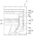
도 4는 도 2에서 "A" 영역을 확대한 액정 표시 장치의 단면도이다.4 is a cross-sectional view of the liquid crystal display device in which the "A" region is enlarged in Fig.
도 4에 도시된 바와 같이, 본 발명의 실시예에서는 가이드 패널(20) 상에 접착 가이드부(70)를 추가로 구비하고, 접착부재(80)를 통해 상기 접착 가이드부(70)에 액정 패널(90)을 접착시킴으로써 상기 액정 패널(90)을 안정적으로 고정시킬 수 있다.4, in the embodiment of the present invention, an
구체적으로 상기 접착 가이드부(70)는 상기 가이드 패널(20)의 수직부(20a) 상에 구비된 베이스부(70a), 상기 베이스부(70a)의 일측과 연결되며 상기 수직부(20a)의 내측면을 감싸면서 상기 가이드 패널(20)의 수평부(20b) 내부로 연장되어 구비된 제1연장부(70b), 및 상기 베이스부(70a)의 타측과 연결되며 상기 수직부(20a)의 외측면을 감싸도록 연장되어 구비된 제2연장부(70c)를 포함한다.More specifically, the
이 때, 내측면은 액정 표시 장치의 내측에서 편광판(50) 및 광학시트(60)와 대향하는 측면을 의미하고, 외측면은 액정 표시 장치의 외측에서 외부와 대향하는 측면을 의미한다.In this case, the inner side means the side facing the
구체적으로, 전술한 바와 같이 상기 가이드 패널(20)은 금속 물질로 구비되고 상기 접착 가이드부(70)는 비금속 물질로 구비되기 때문에, 상기 가이드 패널(20) 상에 상기 접착 가이드부(70)를 고정시키기 위해 접착부재를 이용할 경우 마찬가지로 상기 접착부재와 상기 가이드 패널(20) 간의 약한 결합력으로 인해서 액정 패널(90)이 떨어져 나가는 문제가 동일하게 발생할 수 있다.Specifically, as described above, since the
따라서, 본 발명의 실시예에서 상기 접착 가이드부(70)는 상기 가이드 패널(20) 상에 구비되는 한편, 일부 영역에서는 상기 가이드 패널(20)의 내측까지 연장되도록 구비되기 때문에, 별도의 접착부재 없이 상기 접착 가이드부(70)는 상기 가이드 패널(20) 상에 고정될 수 있다.Therefore, in the embodiment of the present invention, the
더불어, 상기 제1연장부(70b)는 상기 베이스부(70a)와 연결되지 않는 일측이 상기 수직부(20a) 또는 수평부(20b)의 내측으로 절곡되어 구비되고, 상기 제2연장부(70c)는 상기 베이스부(70a)와 연결되지 않는 일측이 상기 수직부(20a)의 내측으로 절곡되어 구비될 수 있다.The
이와 같이, 상기 제1연장부(70b) 및 상기 제2연장부(70c)가 상기 가이드 패널(20) 내측에서 절곡되어 있기 때문에 상기 접착 가이드부(70)에 외력이 발생하더라도 상기 접착 가이드부(70)는 상기 가이드 패널(20)로부터 유격(裕隔)되지 않고 고정적으로 결합되어 있게 된다.Since the
이하에서는, 상기의 구조와 다른 구조를 갖는 상기 접착 가이드부(70)의 다양한 실시예를 살펴보기로 한다.Hereinafter, various embodiments of the
도 5a 내지 도 5c는 본 발명의 실시예에 따른 액정 표시 장치의 접착 가이드부의 다양한 형상을 나타낸 단면도이다.5A to 5C are cross-sectional views illustrating various shapes of an adhesion guide unit of a liquid crystal display device according to an embodiment of the present invention.
도 5a는 제1연장부(70b)가 상기 가이드 패널(20)의 수평부(20b)의 내측으로 두 번에 걸쳐서 절곡되어 구비되고, 제2연장부(70c)가 상기 가이드 패널(20)의 수직부(20a)의 내측으로 절곡되어 구비된 접착 가이드부(70)를 나타내고, 도 5b는 제1연장부(70b)가 상기 가이드 패널(20)의 내측에서 서로 다른 방향으로 두 번에 걸쳐서 절곡되어 구비되고, 제2연장부(70c)가 상기 가이드 패널(20)의 수직부(20a)의 내측으로 절곡되어 제1연장부(70b) 보다 긴 길이로 구비된 접착 가이드부(70)를 나타내고, 도 5c는 제1연장부(70b)가 상기 가이드 패널(20)의 내측에서 서로 다른 방향으로 두 번에 걸쳐서 절곡되어 구비되고, 제2연장부(70c)가 상기 가이드 패널(20)의 수직부(20a)의 내측으로 절곡되어 제1연장부(70b) 보다 짧은 길이로 구비된 접착 가이드부(70)를 나타낸다.5A shows a state in which the first
도 5a 내지 도 5c는 본 발명의 실시예에 따른 접착 가이드부(70)의 다양한 실시예를 도시한 것일 뿐, 본 발명은 이에 한정되지 않는다. 즉, 상기 접착 가이드부(70)는 상기 가이드 패널(20) 상에 구비되면서 고정되어 있을 수 있는 다양한 형상으로 절곡되어 구비될 수 있을 것이다.5A to 5C illustrate various embodiments of the
또한, 상기 가이드 패널(20) 상에 상기 접착 가이드부(70)를 결합시키는 방법을 살펴보면, 도 5a 내지 도 5c에 도시된 바와 같이 상기 가이드 패널(20)의 수직부를 감싸는 형태로 상기 접착 가이드부(70)를 형성하고, 상기 접착 가이드부(70)의 형상에 대응되는 오목한 형상을 내부에 포함하도록 상기 가이드 패널(20)을 형성하고, 상기 가이드 패널(20)에 상기 접착 가이드부(70)를 끼워 넣는 방식으로 상기 가이드 패널(20) 상에 상기 접착 가이드부(70)를 결합시킬 수 있다. 다만, 본 발명은 이에 한정되는 것은 아니므로 기재하지 않은 다양한 방식으로 상기 가이드 패널(20) 상에 상기 접착 가이드부(70)를 결합시킬 수 있을 것이다.As shown in FIGS. 5A to 5C, the
도 6은 본 발명의 제3실시예에 따른 액정 표시 장치의 단면도로서, 이는 별도의 접착 가이드부를 구비하지 않고 가이드 패널(20)을 이종 물질로 형성한 것을 제외하고 전술한 도 2에 따른 액정 표시 장치와 동일하다. 따라서, 동일한 구성에 대해서는 동일한 도면부호를 부여하였고, 이하에서는 상이한 구성에 대해서만 설명하기로 한다.6 is a cross-sectional view of a liquid crystal display device according to a third embodiment of the present invention, except that the
도 6에 도시된 바와 같이, 본 발명의 제3실시예에 따르면 상기 가이드 패널(20)은 접착부재(80)와 접하는 영역에 구비되는 제1가이드 패널(21) 및 상기 제1가이드 패널(21)을 제외한 나머지 영역에 구비되는 제2가이드 패널(22)을 포함하여 이루어지고, 상기 제1가이드 패널(21)과 상기 제2가이드 패널(22)은 서로 다른 물질로 구비된다.6, according to the third embodiment of the present invention, the
특히, 본 발명의 실시예에서는 네로우 베젤을 구현할 수 있도록 케이스 탑을 제거하는 한편, 확산판(50), 광학시트(60) 및 액정 패널(90)을 상기 가이드 패널(20)만으로 지지할 수 있어야 한다. 즉, 상기 가이드 패널(20)은 상기 확산판(50), 광학시트(60) 및 액정 패널(90)을 지지할 수 있는 정도의 일정 수준 이상의 강도를 만족시켜야 한다.Particularly, in the embodiment of the present invention, the case top can be removed so that the narrow bezel can be realized, and the
따라서, 본 발명의 실시예에서 상기 제2가이드 패널(22)은 상기 제1가이드 패널(21) 보다 상대적으로 강한 강도로 구비됨으로써 상기 확산판(50) 및 광학시트(60)를 지지하는 한편, 상부의 제1가이드 패널(21)을 함께 지지할 수 있다. 구체적으로 상기 제1가이드 패널(21)은 상기 액정 패널(90)을 지지하고, 상기 제2가이드 패널(22)은 상기 확산판(50) 및 광학시트(60)를 지지함으로써, 액정 표시 장치를 모듈화할 수 있다.Therefore, in the embodiment of the present invention, the
또한, 상기 제1가이드 패널(21)은 상기 제2가이드 패널(22) 보다 상기 접착부재(80)에 대한 접착력이 강한 물질로 구비됨으로써 상기 가이드 패널(20)과 상기 접착부재(80)의 분리를 방지하고 상기 액정 패널(90)을 안정적으로 접착시킬 수 있다.The
즉, 종래에는 가이드 패널의 강도를 확보할 수 있도록 금속 압출과 같은 방식으로 가이드 패널을 형성하였으나, 이 경우 탄성 레진으로 구비되는 접착부재는 유리 물질의 액정 패널과는 강한 접착력을 유지하지만 금속 물질의 가이드 패널과는 강하게 접착되지 못하고, 그로 인해서 액정 패널이 가이드 패널로부터 떨어지는 문제가 있었다.That is, conventionally, the guide panel is formed in the same manner as metal extrusion so as to secure the strength of the guide panel. In this case, the adhesive member provided with the elastic resin maintains a strong adhesive force with the liquid crystal panel of the glass material, There is a problem that the liquid crystal panel does not strongly adhere to the guide panel, thereby causing the liquid crystal panel to fall off from the guide panel.
따라서, 본 발명의 실시예에서 상기 접착부재(80)와 직접 접하는 영역에 구비되는 상기 제1가이드 패널(21)은 상기 제2가이드 패널(22) 보다 상기 접착부재(80)에 대한 접착력이 강한 물질로 구비됨으로써, 상기 액정 패널(90)이 상기 접착부재(80)를 통해 안정적으로 고정될 수 있도록 한다.Therefore, in the embodiment of the present invention, the
이 때, 상기 가이드 패널(20) 전체 영역에 대해서 상기 제1가이드 패널(21)은 상기 액정 패널(90)을 안정적으로 고정시킬 수 있도록 상기 제2가이드 패널(22)의 일부 영역이라도 상기 접착부재(80)와 접하지 않도록 구비됨이 타당하고, 상기 제2가이드 패널(22)은 상기 액정 패널(90)을 안정적으로 지지할 수 있는 소정의 강도를 만족시킬 수 있는 정도의 영역에 구비됨이 타당하다.At this time, the first guide panel (21) can securely fix the liquid crystal panel (90) with respect to the entire area of the guide panel (20) And the
이하에서는, 본 발명의 제3실시예에 따른 액정 표시 장치의 가이드 패널(20)의 구체적인 구조에 대해서 살펴보기로 한다.Hereinafter, a specific structure of the
도 7a 및 도 7b는 도6에서 "A"영역을 확대한 액정 표시 장치의 단면도이다.Figs. 7A and 7B are cross-sectional views of a liquid crystal display device in which the "A" region is enlarged in Fig.
도 7a 및 도 7b에 도시된 바와 같이, 본 발명의 실시예에서 가이드 패널(20)은 접착부재(80)와 직접 접하는 영역을 포함하는 제1가이드 패널(21) 및 상기 제1가이드 패널(21)을 제외한 나머지 영역에 해당하는 제2가이드 패널(22)을 포함하여 이루어진다.7A and 7B, in the embodiment of the present invention, the
특히, 상기 제1가이드 패널(21)과 상기 제2가이드 패널(22)은 서로 안정적으로 결합되어 유격(裕隔)되지 않아야 하므로, 상기 제1가이드 패널(21)과 상기 제2가이드 패널(22)은 서로 접하는 영역에서 볼록부(21a) 및 상기 볼록부(21a)에 대응되는 오목부를 각각 포함하도록 구비될 수 있다.Particularly, since the
일례로 도 7a 및 도 7b에 도시된 바와 같이, 상기 제1가이드 패널(21)은 상기 제2가이드 패널(22)의 내측으로 볼록부(21a)를 포함할 수 있으며, 상기 제2가이드 패널(22)은 상기 제1가이드 패널(21)의 볼록부(21a)에 대응되는 형상을 갖는 오목부를 포함할 수 있다.For example, as shown in FIGS. 7A and 7B, the
또한, 상기 제1가이드 패널(21)과 상기 제2가이드 패널(22)이 단순한 요철 형상으로 구비될 경우 상기 제1가이드 패널(21)로 액정 패널(90)의 상면 방향의 힘이 가해지면 아무런 저항 없이 상기 제1가이드 패널(21)이 상기 제2가이드 패널(22)로부터 분리될 수 있다.When the
따라서, 본 발명의 실시예에서 상기 제1가이드 패널(21)이 볼록부(21a)를 포함하고 상기 제2가이드 패널(22)이 오목부를 포함하는 경우, 도 7a 및 도 7b에 도시된 바와 같이 상기 제1가이드 패널(21)의 볼록부(21a)는 유격을 방지할 수 있도록 상기 제2가이드 패널(22)의 내부에서 다양한 형태로 절곡된 형상으로 구비될 수 있다.Therefore, in the embodiment of the present invention, when the
즉, 상기 제1가이드 패널(21)의 볼록부(21a)가 상기 제2가이드 패널(22)의 내부에서 절곡되어 있기 때문에 상기 제1가이드 패널(21)에 외력이 가해지더라도 상기 볼록부(21a)에 의해 상기 제1가이드 패널(21)은 안정적으로 상기 제2가이드 패널(22)에 고정되어 있을 수 있다.That is, since the
다만, 본 발명은 이에 한정되는 것은 아니므로, 상기 제1가이드 패널(21)이 오목부를 포함하고, 상기 제2가이드 패널(22)이 볼록부를 포함하는 것도 가능하다. 즉, 상기 가이드 패널(20) 전체로서의 강도를 확보할 수 있도록 상기 제2가이드 패널(22)의 면적을 증가시킬 필요가 있는 경우 상기 제2가이드 패널(22)이 볼록부를 포함하도록 구비할 수도 있을 것이다.However, since the present invention is not limited to this, it is also possible that the
도 8은 본 발명의 실시예에 따른 백라이트 유닛을 포함하는 액정 표시 장치의 분해사시도를 도시한 도면이다.8 is an exploded perspective view of a liquid crystal display device including a backlight unit according to an embodiment of the present invention.
도 8에 도시된 바와 같이, 액정 표시 장치는 액정 패널(90), 백라이트 유닛(100), 및 바텀 커버(10)를 포함한다.As shown in Fig. 8, the liquid crystal display includes a
상기 액정 패널(90)은 영상 표시의 핵심적인 역할을 담당하는 부분으로서, 액정층을 사이에 두고 서로 대면 합착된 하부 기판(90a) 및 상부 기판(90b)을 포함한다.The
이 때, 도 8에는 도시되지 않았지만 상기 하부 기판(90a)의 내면에는 복수의 게이트 라인과 데이터 라인이 교차하여 화소(Pixel)가 정의되고, 게이트 라인과 데이터 라인의 각각의 교차점마다 박막 트랜지스터(Thin Film Transistor, TFT)가 구비되어 각 화소에 형성된 투명 화소전극과 일대일로 대응 연결되어 있다.Although not shown in FIG. 8, a plurality of gate lines and data lines intersect the inner surface of the
그리고 상기 상부 기판(90b)의 내면에는 각 화소에 대응되는, 일례로 적(R), 녹(G), 청(B) 컬러의 컬러 필터(Color Filter) 및 이들 각각을 두르며 게이트 라인과 데이터 라인, 및 박막 트랜지스터 등의 비표시 요소를 가리는 블랙 매트릭스(Black Matrix)가 구비된다. 또한, 이들을 덮는 투명 공통전극이 마련되어 있다.On the inner surface of the
다만, 본 발명의 실시예는 이에 한정되는 것은 아니므로, 전술한 컬러 필터는 반드시 상기 상부 기판(90b)에 형성되는 것은 아니고 COT(Color filter On TFT) 타입의 액정 패널(90)의 경우 하부 기판(90a)의 TFT 상에 컬러 필터가 구비되는 것도 가능하다.However, the color filter is not necessarily formed on the
이 같은 상기 액정 패널(90)의 적어도 하나의 가장자리를 따라서 연성회로 기판(Flexible Printed Circuit Board, FPCB) 또는 테이프 캐리어 패키지(Tape Carrier Package, TCP)와 같은 연결부재를 매개로 인쇄회로기판(95)이 연결된다.The printed
이 때, 상기 인쇄회로기판(95)은 각각 게이트 라인으로 박막 트랜지스터의 온/오프 신호를 스캔 전달하는 게이트 구동 회로, 및 데이터 라인으로 가이드 패널별 화상 신호를 전달하는 데이터 구동 회로로 구분되어 상기 액정 패널(90)의 서로 인접한 두 가장자리에 위치될 수 있다.At this time, the printed
그리고 전술한 구조의 상기 액정 패널(90)은 스캔 전달되는 게이트 구동 회로의 온/오프 신호에 의해 각 게이트 라인 별로 선택된 박막 트랜지스터가 온 되면 데이터 구동 회로의 신호 전압이 데이터 라인을 통해서 해당 화소전극으로 전달되고, 이에 따른 화소전극과 공통전극 사이의 전기장에 의해 액정분자의 배열방향이 변화되어 투과율 차이를 나타낸다.When the thin film transistor selected for each gate line is turned on by the on / off signal of the gate driving circuit to be scanned, the
또한, 본 발명의 실시예에 따른 액정 표시 장치에는 상기 액정 패널(90)이 나타내는 투과율의 차이가 외부로 발현되도록 상기 액정 패널(90)의 배면에서 광을 제공하는 백라이트 유닛(100)이 구비된다.The liquid crystal display device according to the embodiment of the present invention is provided with a
상기 백라이트 유닛(100)은 광원 패키지(110), 및 상기 광원 패키지(110)의 상부에 구비되는 확산판(50), 복수의 광학시트(60), 및 상기 광원 패키지(110)의 측부에 구비되는 가이드 패널(20)을 포함한다.The
상기 광원 패키지(110)는 상기 바텀 커버(10)의 길이 방향 내면을 따라 일정한 이격공간을 갖도록 배열되는 PCB(미도시)와, 이들 각각에 실장되는 반사부(30) 및 복수의 광원(40)을 포함한다.The
이 때, PCB는 방열기능을 구비한 메탈코어 인쇄회로기판(Metal Core PCB)이 사용될 수 있으며, 메탈 코어 인쇄회로기판의 배면에는 방열판을 마련하여 각각의 광원(40)으로부터 열을 전달받아 외부로 방출하는 것도 가능하다.In this case, the PCB may be a metal core PCB having a heat dissipating function. A heat sink is provided on the back surface of the metal core printed circuit board to receive heat from the respective
복수의 광학시트(60)는 DBEF(Dual Brightness Enhancement Film)라 불리는 반사형 편광필름이나 프리즘 등 각종 기능성 시트를 포함할 수 있다.The plurality of
따라서, 상기 복수의 광원(40)으로부터 제공되는 광은 상기 확산판(50) 및 광학시트(60)를 차례로 통과한 후 상기 액정 패널(90)로 입사되고, 이를 이용하여 상기 액정 패널(90)은 비로소 고휘도 화상을 외부로 표시할 수 있다.The light from the plurality of
종래의 액정 표시 장치에서 이러한 액정 패널과 백라이트 유닛은 케이스 탑과 가이드 패널 및 바텀 커버를 통해 모듈화 되는데, 본 발명의 실시예에서는 네로우 베젤을 구현할 수 있도록 케이스 탑을 제거하는 한편, 상기 액정 패널(90)을 고정시킬 수 있도록 상기 가이드 패널(20)의 최상부에 상기 액정 패널(90)을 접착시키는 방식으로 모듈화된 액정 표시 장치를 구성한다. 즉, 도 2 및 도 6을 통해 도시한 바와 같이 본 발명의 실시예에서는 상기 가이드 패널(20)을 수직부, 수평부 및 경사부로 구비하고, 상기 수평부 및 경사부를 통해 상기 확산판(50)과 광학시트(60)를 지지하고, 상기 수직부를 통해 상기 확산판(50)과 광학시트(60)의 측면을 감싸면서 상기 액정 패널(90)을 지지한다.In a conventional liquid crystal display device, such a liquid crystal panel and a backlight unit are modularized through a case top, a guide panel and a bottom cover. In the embodiment of the present invention, the case top is removed to realize a narrow bezel, The
상기 바텀 커버(10)는 상기 백라이트 유닛(100)을 수납하는 바닥 케이스 역할을 담당하며, 이를 위하여 각 모서리의 가장자리가 상승되고 상기 바텀 커버(10) 상, 구체적으로 외주면 상에 상기 가이드 패널(20)이 각각 구비되어 그 내부에 소정 공간을 형성한다.The
또한 이러한 상기 바텀 커버(10) 상에 안착되며 상기 액정 패널(90) 및 백라이트 유닛(100)의 가장자리를 두르는 사각테 형상의 가이드 패널(20)이 상기 바텀 커버(10)에 결합된다.A rectangular panel-shaped
특히, 본 발명의 실시예에서는 전술한 바와 같이, 상기 가이드 패널(20)에 상기 액정 패널(90)을 안정적으로 접착시킬 수 있도록, 가이드 패널(20) 보다 접착부재(미도시)에 대한 접착력이 상대적으로 강한 접착 가이드부(미도시)를 상기 가이드 패널(20) 상에 추가로 구비하거나, 상기 가이드 패널(20)을 접착력이 상대적으로 강한 제1가이드 패널(미도시)과 제1가이드 패널 이외의 영역으로 구비되는 제2가이드 패널(미도시)로 나누어 구비함으로써, 상기 가이드 패널(20)과 접착부재 간의 약한 접착력으로 인해 상기 액정 패널(90)이 떨어져 나가는 것을 방지할 수 있다.Particularly, in the embodiment of the present invention, as described above, the adhesion force to the adhesive member (not shown) is higher than that of the
이상 첨부된 도면을 참조하여 본 발명의 실시예들을 더욱 상세하게 설명하였으나, 본 발명은 반드시 이러한 실시예로 국한되는 것은 아니고, 본 발명의 기술사상을 벗어나지 않는 범위 내에서 다양하게 변형 실시될 수 있다. 따라서, 본 발명에 개시된 실시예들은 본 발명의 기술 사상을 한정하기 위한 것이 아니라 설명하기 위한 것이고, 이러한 실시예에 의하여 본 발명의 기술 사상의 범위가 한정되는 것은 아니다. 그러므로, 이상에서 기술한 실시예들은 모든 면에서 예시적인 것이며 한정적이 아닌 것으로 이해해야만 한다. 본 발명의 보호 범위는 청구 범위에 의하여 해석되어야 하며, 그와 동등한 범위 내에 있는 모든 기술 사상은 본 발명의 권리 범위에 포함되는 것으로 해석되어야 할 것이다.Although the embodiments of the present invention have been described in detail with reference to the accompanying drawings, it is to be understood that the present invention is not limited to those embodiments and various changes and modifications may be made without departing from the scope of the present invention. . Therefore, the embodiments disclosed in the present invention are intended to illustrate rather than limit the scope of the present invention, and the scope of the technical idea of the present invention is not limited by these embodiments. Therefore, it should be understood that the above-described embodiments are illustrative in all aspects and not restrictive. The scope of protection of the present invention should be construed according to the claims, and all technical ideas within the scope of equivalents should be interpreted as being included in the scope of the present invention.
10: 바텀 커버20: 가이드 패널
30: 반사부40: 광원
50: 확산판60: 광학시트
70: 접착 가이드부80: 접착부재
90: 액정 패널10: bottom cover 20: guide panel
30: reflector 40: light source
50: diffusion plate 60: optical sheet
70: Adhesive guide portion 80: Adhesive member
90: liquid crystal panel
Claims (9)
Translated fromKorean상기 액정 패널을 지지하는 가이드 패널;
상기 액정 패널과 상기 가이드 패널 사이에 구비되는 접착부재; 및
상기 접착부재에 의해 상기 액정 패널이 접착되도록 상기 가이드 패널 상에 구비되는 접착 가이드부를 포함하되,
상기 접착 가이드부는 상기 가이드 패널 보다 상기 접착부재에 대한 접착력이 강한 물질로 구비되는, 액정 표시 장치.A liquid crystal panel;
A guide panel for supporting the liquid crystal panel;
An adhesive member provided between the liquid crystal panel and the guide panel; And
And an adhesion guide portion provided on the guide panel to adhere the liquid crystal panel by the adhesive member,
Wherein the adhesive guide portion is formed of a material having a strong adhesive force to the adhesive member than the guide panel.
상기 접착 가이드부는 상기 가이드 패널 상에서 상기 접착부재와 접하는 영역에 구비된 베이스부, 상기 베이스부의 일측과 연결되며 상기 가이드 패널의 내측면을 감싸면서 상기 가이드 패널의 내부로 연장되어 구비된 제1연장부, 및 상기 베이스부의 타측과 연결되며 상기 가이드 패널의 외측면을 감싸도록 연장되어 구비된 제2연장부를 포함하는, 액정 표시 장치.The method according to claim 1,
Wherein the adhesive guide portion includes a base portion provided in an area in contact with the adhesive member on the guide panel, a first extension portion connected to one side of the base portion and surrounding the inner side surface of the guide panel, And a second extension part connected to the other side of the base part and extending to cover the outer side surface of the guide panel.
상기 제1연장부는 상기 베이스부와 연결되지 않는 일측이 상기 가이드 패널의 내부에서 절곡되어 구비되고,
상기 제2연장부는 상기 베이스부와 연결되지 않는 일측이 상기 가이드 패널의 내측으로 절곡되어 구비되는, 액정 표시 장치.3. The method of claim 2,
Wherein the first extension portion is bent at one side not connected to the base portion inside the guide panel,
And the second extension part is bent at one side not connected to the base part to the inside of the guide panel.
상기 가이드 패널은 상기 바텀 커버의 하면에 대해서 평행하게 구비된 수평부, 및 상기 바텀 커버의 하면에 대해서 수직으로 구비된 수직부를 포함하고,
상기 접착 가이드부는 상기 수직부 상에 구비된, 액정 표시 장치.The method according to claim 1,
Wherein the guide panel includes a horizontal portion provided parallel to a bottom surface of the bottom cover and a vertical portion provided perpendicularly to a bottom surface of the bottom cover,
And the adhesion guide portion is provided on the vertical portion.
상기 액정 패널의 하부에 구비되어 상기 가이드 패널에 의해 지지되는 확산판을 더 포함하되,
상기 액정 패널은 상기 수직부에 의해서 지지되고, 상기 확산판은 상기 수평부에 의해서 지지되도록 구비된, 액정 표시 장치.5. The method of claim 4,
And a diffusion plate provided at a lower portion of the liquid crystal panel and supported by the guide panel,
Wherein the liquid crystal panel is supported by the vertical portion, and the diffusion plate is supported by the horizontal portion.
상기 가이드 패널은 금속 물질로 구비되고, 상기 접착부재는 탄성 레진(resin)으로 구비되고, 상기 접착 가이드부는 비금속 물질로 구비된, 액정 표시 장치.The method according to claim 1,
Wherein the guide panel is made of a metal material, the adhesive member is made of an elastic resin, and the adhesive guide part is made of a non-metallic material.
상기 액정 패널을 지지하는 가이드 패널; 및
상기 액정 패널과 상기 가이드 패널 사이에 구비되어 상기 액정 패널을 상기 가이드 패널에 접착시키는 접착부재를 포함하되,
상기 가이드 패널은 상기 접착부재와 접하는 영역에 구비되는 제1가이드 패널 및 상기 제1가이드 패널을 제외한 나머지 영역에 구비되는 제2가이드 패널로 이루어지고, 상기 제1가이드 패널은 상기 제2가이드 패널 보다 상기 접착부재에 대한 접착력이 강한 물질로 구비되는, 액정 표시 장치.A liquid crystal panel;
A guide panel for supporting the liquid crystal panel; And
And an adhesive member provided between the liquid crystal panel and the guide panel to adhere the liquid crystal panel to the guide panel,
Wherein the guide panel comprises a first guide panel provided in an area in contact with the adhesive member and a second guide panel provided in an area other than the first guide panel, And is provided with a strong adhesive force to the adhesive member.
상기 액정 패널의 하부에 구비되어 상기 가이드 패널에 의해 지지되는 확산판을 더 포함하고,
상기 액정 패널은 상기 제1가이드 패널에 의해 지지되고, 상기 확산판은 상기 제2가이드 패널에 의해 지지되도록 구비된, 액정 표시 장치.8. The method of claim 7,
And a diffusion plate provided at a lower portion of the liquid crystal panel and supported by the guide panel,
Wherein the liquid crystal panel is supported by the first guide panel and the diffuser plate is supported by the second guide panel.
상기 제1가이드 패널과 상기 제2가이드 패널은 유격(裕隔)을 방지할 수 있도록 서로 접하는 영역에서 볼록부 및 상기 볼록부에 대응되는 오목부를 각각 포함하도록 구비되는, 액정 표시 장치.8. The method of claim 7,
Wherein the first guide panel and the second guide panel each include a convex portion and a concave portion corresponding to the convex portion in an area in contact with each other so as to prevent clearance.
Priority Applications (1)
| Application Number | Priority Date | Filing Date | Title |
|---|---|---|---|
| KR1020150189601AKR20170079244A (en) | 2015-12-30 | 2015-12-30 | Liquid crystal dispaly device |
Applications Claiming Priority (1)
| Application Number | Priority Date | Filing Date | Title |
|---|---|---|---|
| KR1020150189601AKR20170079244A (en) | 2015-12-30 | 2015-12-30 | Liquid crystal dispaly device |
Publications (1)
| Publication Number | Publication Date |
|---|---|
| KR20170079244Atrue KR20170079244A (en) | 2017-07-10 |
Family
ID=59355415
Family Applications (1)
| Application Number | Title | Priority Date | Filing Date |
|---|---|---|---|
| KR1020150189601AWithdrawnKR20170079244A (en) | 2015-12-30 | 2015-12-30 | Liquid crystal dispaly device |
Country Status (1)
| Country | Link |
|---|---|
| KR (1) | KR20170079244A (en) |
Cited By (2)
| Publication number | Priority date | Publication date | Assignee | Title |
|---|---|---|---|---|
| CN109814293A (en)* | 2017-11-20 | 2019-05-28 | 群创光电股份有限公司 | Backlight module and display device |
| US10901252B2 (en) | 2018-01-25 | 2021-01-26 | Samsung Display Co., Ltd. | Display device |
- 2015
- 2015-12-30KRKR1020150189601Apatent/KR20170079244A/ennot_activeWithdrawn
Cited By (3)
| Publication number | Priority date | Publication date | Assignee | Title |
|---|---|---|---|---|
| CN109814293A (en)* | 2017-11-20 | 2019-05-28 | 群创光电股份有限公司 | Backlight module and display device |
| CN109814293B (en)* | 2017-11-20 | 2022-03-01 | 群创光电股份有限公司 | Backlight module and display device |
| US10901252B2 (en) | 2018-01-25 | 2021-01-26 | Samsung Display Co., Ltd. | Display device |
Similar Documents
| Publication | Publication Date | Title |
|---|---|---|
| KR101541352B1 (en) | Liquid crystal display device | |
| JP5679604B2 (en) | Liquid crystal display device and method of manufacturing liquid crystal display device | |
| CN103852920B (en) | LIQUID DISPLAY APPARATUS and manufacturing method thereof | |
| US10473848B2 (en) | Display panel and display apparatus including the same | |
| CN107357063A (en) | Display device and the tiled display equipment for including the display device | |
| KR102230296B1 (en) | Display device | |
| KR20170012659A (en) | Backlight unit and liquid crystal dispaly device including the same | |
| KR102460231B1 (en) | Backlight unit and liquid crystal dispaly device including the same | |
| US20190163008A1 (en) | Display device and multi display device using the same | |
| US20190129236A1 (en) | Display device | |
| US10025126B2 (en) | Display device | |
| CN108121110A (en) | Liquid crystal display device and the electronic device including liquid crystal display device | |
| US20170192147A1 (en) | Display apparatus | |
| CN102169245B (en) | Liquid crystal display | |
| KR101536126B1 (en) | Liquid crystal display | |
| US20160018589A1 (en) | Display device | |
| US8794778B2 (en) | Top chassis assembly and display device having the same | |
| KR101966864B1 (en) | Liquid crystal display apparatus | |
| KR102001855B1 (en) | Liquid crystal display device | |
| KR20160038148A (en) | Display device and method for fabricating the same | |
| KR101463683B1 (en) | Liquid Crystal Display Device | |
| US20150092385A1 (en) | Display apparatus | |
| KR101737799B1 (en) | Light shielding tape and backlight unit using the same and liquid crystal display device having thereof | |
| KR20170079244A (en) | Liquid crystal dispaly device | |
| KR20170077721A (en) | Liquid crystal display device |
Legal Events
| Date | Code | Title | Description |
|---|---|---|---|
| PA0109 | Patent application | Patent event code:PA01091R01D Comment text:Patent Application Patent event date:20151230 | |
| PG1501 | Laying open of application | ||
| PC1203 | Withdrawal of no request for examination |