KR20170077597A - Lens optical system and laser processing apparatus - Google Patents
Lens optical system and laser processing apparatusDownload PDFInfo
- Publication number
- KR20170077597A KR20170077597AKR1020150187640AKR20150187640AKR20170077597AKR 20170077597 AKR20170077597 AKR 20170077597AKR 1020150187640 AKR1020150187640 AKR 1020150187640AKR 20150187640 AKR20150187640 AKR 20150187640AKR 20170077597 AKR20170077597 AKR 20170077597A
- Authority
- KR
- South Korea
- Prior art keywords
- lens portion
- lens
- laser light
- light
- substrate
- Prior art date
- Legal status (The legal status is an assumption and is not a legal conclusion. Google has not performed a legal analysis and makes no representation as to the accuracy of the status listed.)
- Granted
Links
Images


Classifications
- G—PHYSICS
- G02—OPTICS
- G02B—OPTICAL ELEMENTS, SYSTEMS OR APPARATUS
- G02B3/00—Simple or compound lenses
- G02B3/0006—Arrays
- G02B3/0037—Arrays characterized by the distribution or form of lenses
- B—PERFORMING OPERATIONS; TRANSPORTING
- B23—MACHINE TOOLS; METAL-WORKING NOT OTHERWISE PROVIDED FOR
- B23K—SOLDERING OR UNSOLDERING; WELDING; CLADDING OR PLATING BY SOLDERING OR WELDING; CUTTING BY APPLYING HEAT LOCALLY, e.g. FLAME CUTTING; WORKING BY LASER BEAM
- B23K26/00—Working by laser beam, e.g. welding, cutting or boring
- B23K26/02—Positioning or observing the workpiece, e.g. with respect to the point of impact; Aligning, aiming or focusing the laser beam
- B23K26/06—Shaping the laser beam, e.g. by masks or multi-focusing
- B23K26/064—Shaping the laser beam, e.g. by masks or multi-focusing by means of optical elements, e.g. lenses, mirrors or prisms
- B23K26/0648—Shaping the laser beam, e.g. by masks or multi-focusing by means of optical elements, e.g. lenses, mirrors or prisms comprising lenses
- G—PHYSICS
- G02—OPTICS
- G02B—OPTICAL ELEMENTS, SYSTEMS OR APPARATUS
- G02B3/00—Simple or compound lenses
- G—PHYSICS
- G02—OPTICS
- G02B—OPTICAL ELEMENTS, SYSTEMS OR APPARATUS
- G02B3/00—Simple or compound lenses
- G02B2003/0093—Simple or compound lenses characterised by the shape
Landscapes
- Physics & Mathematics (AREA)
- Optics & Photonics (AREA)
- Engineering & Computer Science (AREA)
- General Physics & Mathematics (AREA)
- Plasma & Fusion (AREA)
- Mechanical Engineering (AREA)
- Laser Beam Processing (AREA)
- Lenses (AREA)
Abstract
Translated fromKoreanDescription
Translated fromKorean본 발명은 렌즈 광학계 및 이를 포함하는 레이저 가공장치에 관한 것이다.The present invention relates to a lens optical system and a laser processing apparatus including the same.
기존의 레이저 가공공정에서 레이저 빔은 라인 형태의 빔으로 그 집속 지점은 가공대상물의 가공면 상에 일방향으로 형성되어 있으며 그 깊이는 일정한 구조로 이루어져 있다. 이러한 가공 방식은 넓은 가공 영역을 동일한 깊이로 가공하는데에는 장점을 가지고 있다. 그러나, 이러한 가공 방식은 가공 횟수를 줄임으로써 가공 시간을 단축시키는 것이 필요한 분야, 예를 들면, 투명한 가공 대상물의 절단 등과 같은 분야에는 적용되기 어렵다는 단점이 있다.In the conventional laser machining process, the laser beam is a line-shaped beam whose focusing point is formed in one direction on the machined surface of the object to be machined, and its depth is constant. This machining method has advantages in machining a wide machining area to the same depth. However, such a machining method is disadvantageous in that it is difficult to apply to a field in which it is necessary to shorten the machining time by reducing the number of machining operations, for example, cutting a transparent object to be machined.
본 발명의 일 실시예에 따르면 렌즈 광학계 및 이를 포함하는 레이저 가공장치를 제공한다.According to an embodiment of the present invention, there is provided a lens optical system and a laser processing apparatus including the same.
본 발명의 일 측면에 있어서,In one aspect of the present invention,
광이 입사되는 제1면과, 상기 제1면의 반대쪽에 위치하는 평탄한 제2면을 포함하는 몸체부;A body portion including a first surface on which light is incident and a second flat surface opposite to the first surface;
상기 제2면의 가운데에 위치하도록 마련되는 원형 렌즈부; 및A circular lens portion provided at a center of the second surface; And
상기 제2면에 상기 원형 렌즈부를 둘러싸도록 마련되는 적어도 하나의 환형 렌즈부;를 포함하고,And at least one annular lens portion provided on the second surface so as to surround the circular lens portion,
상기 원형 렌즈부 및 상기 적어도 하나의 환형 렌즈부는 서로 다른 곡률 반경을 가짐으로써 상기 광의 진행 방향을 따라 이격되게 배치되는 복수의 집광점을 형성하는 렌즈 광학계가 제공된다.Wherein the circular lens portion and the at least one annular lens portion have a different radius of curvature to form a plurality of light-converging points spaced apart along the traveling direction of the light.
상기 적어도 하나의 환형 렌즈부 각각은 상기 원형 렌즈부로부터 멀어질수록 두께가 점점 얇아지는 형상을 가질 수 있다.Each of the at least one annular lens portion may have a shape in which the thickness becomes gradually thinner as the distance from the circular lens portion increases.
상기 원형 렌즈부는 상기 적어도 하나의 환형 렌즈부 각각 보다 작은 곡률 반경을 가질 수 있다. 이 경우, 상기 적어도 하나의 환형 렌즈부는 상기 원형 렌즈부로부터 멀어질수록 점점 큰 곡률 반경을 가지는 복수개의 환형 렌즈부를 포함할 수 있다.The circular lens portion may have a radius of curvature smaller than that of each of the at least one annular lens portion. In this case, the at least one annular lens portion may include a plurality of annular lens portions having a gradually increasing radius of curvature from the circular lens portion.
상기 원형 렌즈부와 상기 적어도 하나의 환형 렌즈부 각각은 동일한 광 입사면적을 가질 수 있다. 상기 원형 렌즈부는 상기 적어도 하나의 환형 렌즈부 각각 보다 작은 광 입사면적을 가질 수 있다. 이 경우, 상기 적어도 하나의 환형 렌즈부는 상기 원형 렌즈부로부터 멀어질수록 점점 큰 광 입사면적으로 가지는 복수개의 환형 렌즈부를 포함할 수 있다.Each of the circular lens portion and the at least one annular lens portion may have the same light incidence area. The circular lens portion may have a smaller light incidence area than each of the at least one annular lens portion. In this case, the at least one annular lens portion may include a plurality of annular lens portions having a light incidence area which gradually increases from the circular lens portion.
상기 몸체부의 제1면에는 가우시안 형태, 도그이어 타입 형태 또는 평탄한 형태의 세기(intensity)를 가지는 레이저 빔이 입사될 수 있다.A laser beam having an intensity of a Gaussian shape, a dogleg type, or a flat shape may be incident on the first surface of the body part.
다른 측면에 있어서,In another aspect,
레이저 광을 방출하는 레이저 광원; 및A laser light source for emitting laser light; And
상기 레이저 광원으로부터 출사된 레이저 광을 집속하여 기판에 조사하는 집속 유닛(focusing unit);을 포함하고,And a focusing unit for focusing the laser light emitted from the laser light source and irradiating the laser light onto the substrate,
상기 집속 유닛은,The focusing unit includes:
상기 레이저 광이 입사되는 제1면과, 상기 제1면의 반대쪽에 위치하는 평탄한 제2면을 포함하는 몸체부;A body portion including a first surface on which the laser light is incident and a second flat surface opposite to the first surface;
상기 제2면의 가운데에 위치하도록 마련되는 원형 렌즈부; 및A circular lens portion provided at a center of the second surface; And
상기 제2면에 상기 원형 렌즈부를 둘러싸도록 마련되는 적어도 하나의 환형 렌즈부;를 포함하고,And at least one annular lens portion provided on the second surface so as to surround the circular lens portion,
상기 원형 렌즈부 및 상기 적어도 하나의 환형 렌즈부는 서로 다른 곡률 반경을 가짐으로써 상기 기판의 두께 방향을 따라 이격되게 배치되는 복수의 집광점을 형성하는 레이저 가공장치가 제공된다.Wherein the circular lens portion and the at least one annular lens portion have different radii of curvature to form a plurality of light-converging points spaced apart along the thickness direction of the substrate.
상기 기판은 상기 레이저 광에 대해 투과성을 가지는 물질을 포함할 수 있다. 상기 레이저 가공장치는 상기 기판에 조사되는 상기 레이저 광을 가공 방향을 따라 주사하는 스캔 유닛을 더 포함할 수 있다.The substrate may include a material having transparency to the laser light. The laser machining apparatus may further include a scan unit for scanning the laser beam irradiated on the substrate along a machining direction.
상기 적어도 하나의 환형 렌즈부 각각은 상기 원형 렌즈부로부터 멀어질수록 두께가 점점 얇아지는 형상을 가질 수 있다.Each of the at least one annular lens portion may have a shape in which the thickness becomes gradually thinner as the distance from the circular lens portion increases.
상기 원형 렌즈부는 상기 적어도 하나의 환형 렌즈부 각각 보다 작은 곡률 반경을 가질 수 있다. 이 경우, 상기 적어도 하나의 환형 렌즈부는 상기 원형 렌즈부로부터 멀어질수록 점점큰 곡률 반경을 가지는 복수개의 환형 렌즈부를 포함할 수 있다.The circular lens portion may have a radius of curvature smaller than that of each of the at least one annular lens portion. In this case, the at least one annular lens portion may include a plurality of annular lens portions having a gradually increasing radius of curvature from the circular lens portion.
상기 레이저 광원은 가우시안 형태의 세기를 가지는 레이저 빔을 방출할 수있다. 이 경우, 상기 원형 렌즈부는 상기 적어도 하나의 환형 렌즈부 각각 보다 작은 광 입사면적을 가질 수 있다. 그리고, 상기 적어도 하나의 환형 렌즈부는 상기 원형 렌즈부로부터 멀어질수록 점점큰 광 입사면적으로 가지는 복수개의 환형 렌즈부를 포함할 수 있다.The laser light source may emit a laser beam having a Gaussian intensity. In this case, the circular lens portion may have a smaller light incidence area than each of the at least one annular lens portion. The at least one annular lens portion may include a plurality of annular lens portions having a light incidence area gradually increasing from the circular lens portion.
상기 레이저 광원과 상기 집속 유닛 사이에 마련되어 상기 레이저 광원으로부터 출사된 레이저 빔을 도그이어 타입 형태 또는 평탄한 형태의 세기를 가지도록 변형시키는 빔 성형 유닛을 더 포함할 수 있다. 이 경우, 상기 원형 렌즈부와 상기 적어도 하나의 환형 렌즈부 각각은 동일한 광 입사면적을 가질 수 있다.And a beam shaping unit provided between the laser light source and the focusing unit for deforming the laser beam emitted from the laser light source so as to have a dogle type or a flat type intensity. In this case, each of the circular lens portion and the at least one annular lens portion may have the same light incidence area.
또 다른 측면에 있어서,In yet another aspect,
렌즈 광학계를 이용하여 레이저 광을 집속시켜 기판을 가공하는 방법에 있어서,A method of processing a substrate by focusing a laser beam using a lens optical system,
상기 렌즈 광학계는, 상기 레이저 광이 입사되는 제1면과 상기 제1면의 반대쪽에 위치하는 평탄한 제2면을 포함하는 몸체부와, 상기 제2면의 가운데에 위치하도록 마련되는 원형 렌즈부와, 상기 제2면에 상기 원형 렌즈부를 둘러싸도록 마련되는 적어도 하나의 환형 렌즈부;를 포함하고,Wherein the lens optical system includes a body portion including a first surface on which the laser beam is incident and a second flat surface located on the opposite side of the first surface, a circular lens portion provided to be positioned at the center of the second surface, And at least one annular lens portion provided on the second surface so as to surround the circular lens portion,
상기 원형 렌즈부 및 상기 적어도 하나의 환형 렌즈부는 서로 다른 곡률 반경을 가짐으로써 상기 레이저 광은 상기 렌즈 광학계에 의해 다중 집속되어 상기 기판의 두께 방향을 따라 서로 이격된 복수의 집광점을 형성하는 레이저 가공방법이 제공된다.Wherein the circular lens portion and the at least one annular lens portion have different radii of curvature so that the laser light is multi-focused by the lens optical system to form a plurality of light-converging points spaced apart from each other along the thickness direction of the substrate Method is provided.
상기 기판은 상기 레이저 광에 대해 투과성을 가지는 물질을 포함함으로써 상기 복수의 집광점 중 적어도 하나는 상기 기판의 내부에 형성될 수 있다.The substrate includes a material having a transmittance to the laser light so that at least one of the plurality of light-converging points may be formed inside the substrate.
본 발명의 실시예에 의하면, 렌즈 광학계가 서로 다른 곡률 반경을 가지는 복수의 렌즈부를 포함함으로써 기판의 두께 방향을 따라 복수의 집광점을 동시에 형성할 수 있으므로 투명한 기판의 가공 시간을 단축시킬 수 있다. 즉, 기존에는 기판의 가공 깊이가 달라짐에 따라 가공 공정들을 반복적으로 수행하여야 하지만 본 실시예에 따른 렌즈 광학계를 이용하게 되면 한번의 공정으로 기판을 가공할 수 있으므로 기판의 가공시간을 크게 단축시킬 수 있다.According to the embodiments of the present invention, since the lens optical system includes a plurality of lens portions having different radii of curvature, it is possible to simultaneously form a plurality of light-converging points along the thickness direction of the substrate, thereby shortening the processing time of the transparent substrate. In other words, conventionally, the processing steps must be repeatedly performed as the processing depth of the substrate is changed. However, if the lens optical system according to the present embodiment is used, the substrate can be processed in a single process, have.
기존의 투명한 기판 가공 시에는 기판의 두께 방향을 따라 상부에 하부로 가공하거나 또는 하부에서 상부로 가공하는 등과 같은 가공 방향에 따른 제약이 있었으나, 본 실시예에 따른 렌즈 광학계를 이용하게 되면 기판의 가공 방향에 따른 제약은 사라질 수 있다. 기판의 두께 방향을 따라 형성되는 복수의 집광점이 가공 조건에 맞는 유효 초점 거리를 갖도록 함으로써 다른 광학계의 성능에 의존하는 불안정성을 해소하고, 에너지도 효율적으로 사용할 수 있다.In the conventional transparent substrate processing, there is a limitation in the processing direction such as processing downward at the upper portion along the thickness direction of the substrate or processing the upper portion from the lower portion. However, if the lens optical system according to the present embodiment is used, Directional constraints can disappear. The plurality of light converging points formed along the thickness direction of the substrate have an effective focal length suited to the processing conditions, thereby relieving instability depending on the performance of other optical systems, and using energy efficiently.
렌즈 광학계를 구성하는 복수의 렌즈부에 대한 곡률 반경이나 렌즈부들 사이의 간격을 조절함으로써 수차 및 초점 거리를 다양하게 조절할 수 있다. 또한, 서로 다른 곡률 반경을 가지는 복수의 렌즈부를 몸체부의 평면 상에 마련함으로써 기존에 사용되었던 다초점 광학계에 비해 그 두께를 얇고 가볍게 할 수 있다. 이러한 렌즈 광학계는 금형을 이용하여 제작될 수 있으므로 기존에 폴리싱 방법을 이용하여 생산하는 방식에 비해 대량 생산이 용이하다. 이종 물질을 포함하는 투명한 기판, 예를 들면 절연층과 실리콘 웨이퍼 등과같이 다층으로 구성된 웨이퍼 기판도 한번의 공정으로 가공이 가능하며, 이에 따라 가공 시간도 단축시킬 수 있다.The aberration and the focal length can be variously adjusted by controlling the radius of curvature and the distance between the lens portions of the plurality of lens units constituting the lens optical system. In addition, by providing a plurality of lens units having different radii of curvature on the plane of the body portion, the thickness of the lens unit can be made thinner and lighter than the conventional multifocal optical system. Since such a lens optical system can be manufactured using a mold, it is easier to mass-produce than a conventional method using a polishing method. A transparent substrate including a heterogeneous material, for example, a wafer substrate composed of a multilayer structure such as an insulating layer and a silicon wafer can be processed in a single step, thereby shortening the processing time.
도 1은 본 발명의 예시적인 실시예에 따른 렌즈 광학계를 도시한 단면도이다.
도 2는 도 1에 도시된 렌즈 광학계의 저면을 도시한 것이다.
도 3은 레이저 광이 도 1에 도시된 렌즈 광학계에 입사되어 기판에 복수의집광점을 형성하는 모습을 도시한 것이다.
도 4a 내지 도 4d는 도 1에 도시된 렌즈 광학계를 제조하는 방법을 도시한 것이다.
도 5는 본 발명의 다른 예시적인 실시예에 따른 레이저 가공장치를 개략적으로 도시한 것이다.
도 6은 도 5에 도시된 레이저 가공장치에서 레이저 광이 집속 유닛을 통해 기판에 조사되는 모습을 도시한 것이다.
도 7은 본 발명의 또 다른 예시적인 실시예에 따른 레이저 가공장치를 개략적으로 도시한 것이다.
도 8은 도 7에 도시된 레이저 가공장치에서 레이저 광이 집속 유닛을 통해 기판에 조사되는 모습을 도시한 것이다.1 is a sectional view showing a lens optical system according to an exemplary embodiment of the present invention.
Fig. 2 shows the bottom surface of the lens optical system shown in Fig.
3 shows a state in which laser light is incident on the lens optical system shown in Fig. 1 to form a plurality of light-converging points on the substrate.
Figs. 4A to 4D show a method of manufacturing the lens optical system shown in Fig. 1. Fig.
5 schematically shows a laser machining apparatus according to another exemplary embodiment of the present invention.
Fig. 6 shows a state in which laser light is irradiated on the substrate through the focusing unit in the laser processing apparatus shown in Fig. 5;
7 schematically shows a laser processing apparatus according to another exemplary embodiment of the present invention.
Fig. 8 shows a state in which laser light is irradiated onto the substrate through the focusing unit in the laser processing apparatus shown in Fig. 7;
이하, 첨부된 도면을 참조하여 본 발명의 실시예를 상세히 설명한다. 아래에 예시되는 실시예는 본 발명의 범위를 한정하는 것은 아니며, 본 발명을 이 기술 분야에서 통상의 지식을 가진 자에게 설명하기 위해서 제공되는 것이다. 도면에서 동일한 참조부호는 동일한 구성요소를 지칭하며, 각 구성요소의 크기나 두께는 설명의 명료성을 위하여 과장되어 있을 수 있다. 또한, 소정의 물질층이 기판에 존재한다고 설명될 때, 그 물질층은 기판에 직접 접하면서 존재할 수도 있고, 그 사이에 다른 제3의 층이 존재할 수도 있다.Hereinafter, embodiments of the present invention will be described in detail with reference to the accompanying drawings. The embodiments illustrated below are not intended to limit the scope of the invention, but rather are provided to illustrate the invention to those skilled in the art. In the drawings, like reference numerals refer to like elements, and the size and thickness of each element may be exaggerated for clarity of explanation. Also, when it is described that a certain material layer is present on a substrate, the material layer may be present in direct contact with the substrate, and there may be another third layer in between.
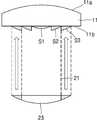
도 1은 본 발명의 예시적인 실시예에 따른 렌즈 광학계를 도시한 단면도이다. 그리고, 도 2는 도 1에 도시된 렌즈 광학계의 저면을 도시한 것이다.1 is a sectional view showing a lens optical system according to an exemplary embodiment of the present invention. 2 shows the bottom surface of the lens optical system shown in Fig.
도 1 및 도 2를 참조하면, 렌즈 광학계(10)는 몸체부(11)와 이 몸체부(11)에 마련되는 서로 다른 곡률 반경을 가지는 복수의 렌즈부(S1,S2,S3,S4)를 포함한다. 몸체부(11)는 광이 입사되는 제1면(11a)과 이 제1면(11a)의 반대쪽에 위치하는 제2면(11b)을 포함할 수 있다. 이러한 몸체부(11)는 입사되는 광을 투과시키는 투명한 재질을 포함할 수 있다.1 and 2, the lens
몸체부(11)의 제1면(11a, 도 1에서 상면)은 광이 입사하는 면으로서 볼록한 형태를 가질 수 있다. 하지만, 반드시 이에 한정되는 것은 아니며 제1면(11a)은 평탄한 형태 또는 오목한 형태를 가지는 것도 가능하다. 그리고, 몸체부(11)의 제2면(11b, 도 1에서 하면)은 제1면(11)으로부터 입사된 광이 투과하는 면으로서 평탄한 형태를 가질 수 있다.The
몸체부(11)의 평탄한 제2면(11b)에는 서로 다른 곡률반경을 가지는 복수의 렌즈부(S1,S2,S3,S4)가 마련되어 있다. 이러한 복수의 렌즈부(S1,S2,S3,S4)는 제1 렌즈부(S1)와 이 제1 렌즈부(S1)를 순차적으로 둘러싸도록 마련되는 제2, 제3 및 제4 렌즈부(S2,S3,S4)를 포함할 수 있다.A plurality of lens sections S1, S2, S3, and S4 having different radii of curvature are provided on the flat
제1 렌즈부(S1)는 제2면(11b)의 가운데 부분에 마련되는 원형 렌즈부가 될 수 있다. 이러한 제1 렌즈부(S1)는 제1 곡률 반경을 가질 수 있다. 그리고, 제2, 제3 및 제4 렌즈부(S2,S3,S4) 각각은 제1 렌즈부(S1)를 순차적으로 둘러싸는 환형 렌즈부가 될 수 있다. 구체적으로, 제2 렌즈부(S2)는 제1 렌즈부(S1)를 둘러싸도록 마련되어 있으며, 제3 렌즈부(S3)는 제2 렌즈부(S2)를 둘러싸도록 마련되어 있다. 그리고, 제4 렌즈부(S4)는 제3 렌즈부(S3)를 둘러싸도록 마련되어 있다. 이러한 제2, 제3 및 제4 렌즈부(S2,S3,S4)는 각각 제2, 제3 및 제4 곡률반경을 가질 수 있다. 여기서, 제2, 제3 및 제4 렌즈부(S2,S3,S4)는 각각 도 1에 도시된 바와 같이 제1 렌즈부(S1)로부터 멀어질수록 그 두께가 점점 얇아지는 형상을 가질 수 있다.The first lens unit S1 may be a circular lens unit provided at the center of the
본 실시예에서, 제1, 제2, 제3 및 제4 렌즈부(S1,S2,S3,S4)는 서로 다른 곡률 반경을 가질 수 있다. 예를 들면, 제1, 제2, 제3 및 제4 렌즈부(S1,S2,S3,S4)는 제1 렌즈부로부터 멀어질수록 큰 곡률 반경들을 가질 수 있다. 이에 따라, 제1, 제2, 제3 및 제4 렌즈부(S1,S2,S3,S4)는 순차적으로 그 값이 커지는 제1, 제2, 제3 및 제4 곡률 반경을 가질 수 있다. 하지만, 반드시 이에 한정되는 것은 아니며, 이외에도 제1, 제2, 제3 및 제4 렌즈부(S1,S2,S3,S4)는 서로 다른 다양한 값의 곡률 반경을 가질 수도 있다.In this embodiment, the first, second, third, and fourth lens units S1, S2, S3, and S4 may have different radii of curvature. For example, the first, second, third, and fourth lens units S1, S2, S3, and S4 may have larger radius of curvature as they move away from the first lens unit. Accordingly, the first, second, third, and fourth lens units S1, S2, S3, and S4 may have first, second, third, and fourth radiuses of curvature that increase sequentially. However, the present invention is not limited thereto, and the first, second, third, and fourth lens units S1, S2, S3, and S4 may have different radii of curvature with different values.
이와 같이, 렌즈 광학계(10)가 서로 다른 곡률 반경을 가지는 제1, 제2, 제3 및 제4 렌즈부(S1,S2,S3,S4)를 포함함으로써 후술하는 바와 같이 광의 진행 방향을 따라 서로 다른 초점 거리를 가지는 복수의 집광점이 형성될 수 있다.As described above, since the lens
도 3은 레이저 광이 도 1에 도시된 렌즈 광학계에 입사되어 기판에 복수의집광점을 형성하는 모습을 도시한 것이다. 여기서, 제1, 제2, 제3 및 제4 렌즈부(S1,S2,S3,S4)는 순차적으로 커지는 제1, 제2, 제3 및 제4 곡률 반경을 가지고 있다. 그리고, 기판(W)으로는 레이저 광을 투과시킬 수 있는 투명한 재질의 기판이 사용되었다.3 shows a state in which laser light is incident on the lens optical system shown in Fig. 1 to form a plurality of light-converging points on the substrate. Here, the first, second, third, and fourth lens units S1, S2, S3, and S4 have first, second, third, and fourth curvature radii sequentially increasing. As the substrate W, a substrate made of a transparent material capable of transmitting laser light was used.
도 3을 참조하면, 레이저 광(L)은 몸체부(11)의 제1면(11a)을 통해 입사되어 몸체부(11)를 투과한 다음, 제1, 제2, 제3 및 제4 렌즈부(S1,S2,S3,S4)에 의해 집속되어 기판(W)에 조사된다. 여기서, 제1, 제2, 제3 및 제4 렌즈부(S1,S2,S3,S4)는 서로 다른 곡률 반경을 가지고 있으므로, 레이저 광(L)의 진행 방향, 즉 기판(W)의 두께 방향을 따라 서로 다른 초점 거리를 가지는 복수의 집광점(P1,P2,P3,P4)을 형성하게 된다.3, the laser light L is incident on the
구체적으로, 제1 렌즈부(S1)는 가장 작은 제1 곡률 반경을 가지고 있으므로 가장 짧은 초점 거리를 형성할 수 있다. 이에 따라, 레이저 광(L) 중에서 제1 렌즈부(S1)로 입사되는 제1 레이저 광(L1)은 제1 렌즈부(S1)에 의해 집속되어 예를 들면 기판(W)의 상면에 제1 집광점(P1)을 형성할 수 있다. 또한, 제2 렌즈부(S2)는 제1 곡률 반경보다 큰 제2 곡률 반경을 가지고 있으므로 제1 렌즈부(S1)보다 큰 초점 거리를 형성할 수 있다. 이에 따라, 레이저 광(L) 중에서 제2 렌즈부(S2)로 입사되는 제2 레이저 광(L2)은 제2 렌즈부(S2)에 의해 집속되어 기판(W)의 내부에 제2 집광점(P2)을 형성할 수 있다. 여기서, 제2 집광점(P2)은 기판(W)의 상면으로부터 소정 깊이 d1에 형성될 수 있다.Specifically, since the first lens unit S1 has the smallest first radius of curvature, the shortest focal length can be formed. The first laser light L1 incident on the first lens unit S1 among the laser light L is focused by the first lens unit S1 and is focused on the upper surface of the substrate W, The light-converging point P1 can be formed. Also, since the second lens unit S2 has the second radius of curvature larger than the first radius of curvature, a larger focal length than the first lens unit S1 can be formed. The second laser light L2 incident on the second lens unit S2 from among the laser light L is converged by the second lens unit S2 to the inside of the substrate W at the second light- P2) can be formed. Here, the second light-converging point P2 may be formed at a predetermined depth d1 from the upper surface of the substrate W. [
제3 렌즈부(S3)는 제2 곡률 반경보다 큰 제3 곡률 반경을 가지고 있으므로 제2 렌즈부(S2)보다 큰 초점 거리를 형성할 수 있다. 이에 따라, 레이저 광(L) 중에서 제3 렌즈부(S3)로 입사되는 제3 레이저 광(L3)은 제3 렌즈부(S3)에 의해 집속되어 기판(W)의 내부에 제3 집광점(P3)을 형성할 수 있다. 여기서, 제3 집광점(P3)은 기판(W)의 상면으로부터 소정 깊이 d2 (>d1)에 형성될 수 있다. 그리고, 제4 렌즈부(S4)는 제3 곡률 반경보다 큰 제4 곡률 반경을 가지고 있으므로 제3 렌즈부(S3)보다 큰 초점 거리를 형성할 수 있다. 이에 따라, 레이저 광 중(L)에서 제4 렌즈부(S4)로 입사되는 제4 레이저 광(L4)은 제4 렌즈부(S4)에 의해 집속되어 기판(W)의 내부에 제4 집광점(P4)을 형성할 수 있다. 여기서, 제4 집광점(P4)은 기판(W)의 상면으로부터 소정 깊이 d3 (>d2)에 형성될 수 있다.Since the third lens unit S3 has a third radius of curvature larger than the second radius of curvature, a larger focal length than the second lens unit S2 can be formed. The third laser light L3 that is incident on the third lens unit S3 among the laser light L is focused by the third lens unit S3 and is focused on the inside of the substrate W at the third light- P3) can be formed. Here, the third light-converging point P3 may be formed at a predetermined depth d2 (> d1) from the top surface of the substrate W. Since the fourth lens unit S4 has the fourth radius of curvature larger than the third radius of curvature, a larger focal length than the third lens unit S3 can be formed. The fourth laser light L4 that is incident on the fourth lens section S4 from the laser light L is focused by the fourth lens section S4 and is focused on the fourth light- (P4) can be formed. Here, the fourth light-converging point P4 may be formed at a predetermined depth d3 (> d2) from the upper surface of the substrate W.
이상과 같이, 렌즈 광학계(10)가 서로 다른 곡률 반경을 가지는 제1, 제2, 제3 및 제4 렌즈부(S1,S2,S3,S4)를 포함함으로써 레이저 광(L)의 진행 방향, 즉 기판(W)의 두께 방향을 따라 소정 간격으로 이격된 제1, 제2, 제3 및 제4 집광점(P1,P2,P3,P4)을 동시에 형성할 수 있다. 이와 같이, 기판(W)에 두께 방향을 따라 복수의 집광점(P1,P2,P3,P4)을 동시에 형성하게 되면 후술하는 바와 같이 기판(W)에 대한 레이저 가공 시간을 크게 단축시킬 수 있다.As described above, since the lens
몸체부(11)의 제1면(11a)에 입사되는 레이저 광(L)은 제1면(11a) 상의 위치에 무관하게 거의 균일한 세기를 가지는 도그이어 타입 형태 또는 평탄한 형태의 광이 될 수 있다. 여기서, 도그이어 타입 형태의 빔이라 함은 그 세기가 가운데는 평탄하고 양끝이 뾰족한 형태의 빔을 의미한다. 이 경우, 기판(W)의 두께 방향을 따라 형성되는 제1, 제2, 제3 및 제4 집광점(P1,P2,P3,P4)이 동일한 에너지 밀도를 가질 수 있도록 제1, 제2, 제3 및 제4 렌즈부(S1,S2,S3,S4)는 동일한 광 입사면적을 가질 수 있다. 한편, 몸체부(11)의 제1면(11a)에 입사되는 레이저 광(L)은 제1면(11a)의 중심부에서 가장자리 부분으로 갈수록 그 세기가 점점 작아지는 가우시안(Gaussian) 형태의 광이 될 수도 있다. 이 경우, 기판(W)의 두께 방향을 따라 형성되는 제1, 제2, 제3 및 제4 집광점(P1,P2,P3,P4)이 동일한 에너지 밀도를 가질 수 있도록 제1, 제2, 제3 및 제4 렌즈부(S1,S2,S3,S4)는 서로 다른 광 입사면적을 가질 수 있다. 구체적으로, 제1, 제2, 제3 및 제4 렌즈부(S1,S2,S3,S4)는 점점 큰 값을 가지는 광 입사면적을 가질 수 있다.The laser light L incident on the
이상의 렌즈 광학계(10)에서는 원형 렌즈부인 제1 렌즈부(S1)를 둘러싸도록 3개의 제2, 제3 및 제4 렌즈부(S2,S3,S4)가 마련된 경우가 설명되었다. 하지만, 이에 한정되는 것은 아니며, 제1 렌즈부(S1)를 둘러싸는 환형 렌즈부들의 개수는 기판(W)의 가공 조건이나 렌즈 광학계(10)의 설계 조건에 따라 얼마든지 변형 가능하다.In the above-described lens
이상에서 설명된 렌즈 광학계(10)를 이용하여 기판(W)을 가공하는 경우에 다음과 같은 효과를 가져올 수 있다.The following effects can be obtained when the substrate W is processed by using the lens
렌즈 광학계(10)가 서로 다른 곡률 반경을 가지는 복수의 렌즈부(S1,S2,S3,S4)를 포함함으로써 기판(W)의 두께 방향을 따라 복수의 집광점(P1,P2,P3,P4)을 동시에 형성할 수 있으므로 기판(W)의 가공 시간을 단축시킬 수 있다. 즉, 기존에는 기판(W)의 가공 깊이가 달라짐에 따라 가공 공정들을 반복적으로 수행하여야 하지만 본 실시예에 따른 렌즈 광학계(10)를 이용하게 되면 한번의 공정으로 기판(W)을 가공할 수 있으므로 가공시간을 크게 단축시킬 수 있다.The lens
기존의 투명한 기판 가공 시에는 기판의 두께 방향을 따라 상부에 하부로 가공하거나 또는 하부에서 상부로 가공하는 등과 같은 가공 방향에 따른 제약이 있었으나, 본 실시예에 따른 렌즈 광학계(10)를 이용하게 되면 기판(W)의 가공 방향에 따른 제약은 사라질 수 있다. 기판(W)의 두께 방향을 따라 형성되는 복수의 집광점(P1,P2,P3,P4)이 가공 조건에 맞는 유효 초점 거리를 갖도록 함으로써 다른 광학계의 성능에 의존하는 불안정성을 해소하고, 에너지도 효율적으로 사용할 수 있다.In the case of using a lens
렌즈 광학계(10)를 구성하는 복수의 렌즈부(S1,S2,S3,S4)에 대한 곡률 반경이나 렌즈부들(S1,S2,S3,S4) 사이의 간격을 조절함으로써 수차 및 초점 거리를 다양하게 조절할 수 있다. 또한, 서로 다른 곡률 반경을 가지는 복수의 렌즈부(S1,S2,S3,S4)를 몸체부(11)의 평면에 마련함으로써 기존에 사용되었던 다초점 광학계에 비해 그 두께를 얇고 가볍게 할 수 있다.The aberration and the focal length can be variously adjusted by adjusting the radius of curvature and the distance between the lens portions S1, S2, S3, and S4 for the plurality of lens portions S1, S2, S3, and S4 constituting the lens
이러한 렌즈 광학계(10)는 금형을 이용하여 제작될 수 있으므로 기존에 폴리싱 방법을 이용하여 생산하는 방식에 비해 대량 생산이 용이하다. 이종 물질을 포함하는 투명한 기판, 예를 들면 절연층과 실리콘 웨이퍼 등과같이 다층으로 구성된 웨이퍼 기판도 한번의 공정으로 가공이 가능하며, 이에 따라 가공 시간도 단축시킬 수 있다.Since the lens
도 4a 내지 도 4d는 도 1에 도시된 렌즈 광학계를 제조하는 방법을 도시한 것이다.Figs. 4A to 4D show a method of manufacturing the lens optical system shown in Fig. 1. Fig.
도 4a를 참조하면, 몸체부(11)를 준비한다. 여기서, 광이 입사하는 몸체부(11)의 제1면(11a)은 볼록한 형태를 가질 수 있다. 하지만, 이에 한정되는 것은 아니며, 몸체부(11)의 제1면(11a)이 평탄한 형태나 또는 오목한 형태를 가지는 것도 가능하다. 그리고, 몸체부(11)의 제2면(11b)을 평탄한 형태를 가질 수 있다. 다음으로, 몸체부(11)의 평탄한 제2면(11b)에 제1 곡률 반경을 가지는 제1 렌즈부(S1)를 결합한다. 여기서, 제1 렌즈부(S1)는 원형 렌즈부로서 제2면(11b)의 가운데 부분에 부착될 수 있다. 이러한 제1 렌즈부(S1)는 제1 곡률 반경을 가지는 제1 렌즈 부재(21)를 소정 크기의 원형 렌즈로 가공함으로써 제작될 수 있다.Referring to FIG. 4A, the
도 4b를 참조하면, 몸체부(11)의 평탄한 제2면(11b)에 제1 렌즈부(S1)를 둘러싸도록 제2 렌즈부(S2)를 결합한다. 여기서, 제2 렌즈부(S2)는 제1 곡률 반경과 다른 제2 곡률 반경을 가질 수 있다. 제2 렌즈부(S2)는 환형 렌즈부로서 제1 렌즈부(S1)를 둘러싸는 형태를 가지고 제2면(11b)에 부착될 수 있다. 이러한 제2 렌즈부(S2)는 제2 곡률 반경을 가지는 제2 렌즈 부재(22)를 제1 렌즈부(S!)보다 큰 크기의 환형 렌즈로 가공함으로써 제작될 수 있다.Referring to FIG. 4B, the second lens unit S2 is coupled to the second
도 4c를 참조하면, 몸체부(11)의 평탄한 제2면(11b)에 제2 렌즈부(S2)를 둘러싸도록 제3 렌즈부(S3)를 결합한다. 여기서, 제3 렌즈부(S3)는 제1 및 제2 곡률 반경과 다른 제3 곡률 반경을 가질 수 있다. 제3 렌즈부(S3)는 환형 렌즈부로서 제2 렌즈부(S2)를 둘러싸는 형태를 가지고 제2면(11b)에 부착될 수 있다. 이러한 제3 렌즈부(S3)는 제3 곡률 반경을 가지는 제3 렌즈 부재(23)를 제2 렌즈부(S2) 보다 큰 크기의 환형 렌즈로 가공함으로써 제작될 수 있다.Referring to FIG. 4C, the third lens unit S3 is coupled to the second
도 4d를 참조하면, 몸체부(11)의 제2면(11b)에 제3 렌즈부(S3)를 둘러싸도록 제4 렌즈부(S4)를 결합하면 도 1에 도시된 렌즈 광학계(10)가 완성된다. 여기서, 제4 렌즈부(S4)는 제1, 제2 및 제3 곡률 반경과 다른 제4 곡률 반경을 가질 수 있다. 제4 렌즈부(S4)는 환형 렌즈부로서 제3 렌즈부(S3)를 둘러싸는 형태를 가지고 제2면(11b)에 부착될 수 있다. 이러한 제4 렌즈부(S4)는 제4 곡률 반경을 가지는 제4 렌즈 부재(24)를 제3 렌즈부(S3) 보다 큰 크기의 환형 렌즈로 가공함으로써 제작될 수 있다.4D, when the fourth lens unit S4 is coupled to the
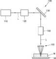
도 5는 본 발명의 다른 예시적인 실시예에 따른 레이저 가공장치를 개략적으로 도시한 것이다. 그리고, 도 6은 도 5에 도시된 레이저 가공장치에서 레이저 광이 집속 유닛을 통해 기판에 조사되는 모습을 도시한 것이다.5 schematically shows a laser machining apparatus according to another exemplary embodiment of the present invention. 6 shows a state in which laser light is irradiated onto the substrate through the focusing unit in the laser processing apparatus shown in Fig.
도 5 및 도 6을 참조하면, 레이저 가공장치(100)는 레이저 광(L)을 방출하는 레이저 광원(110)과, 레이저 광원(110)으로부터 출사된 레이저 광(L)을 집속하여 기판(W)에 조사하는 집속 유닛(150)을 포함한다. 가공 대상물인 기판(W)은 스테이지(50) 상에 장착될 수 있다. 이러한 기판(W)으로는 레이저 광(L)에 대해 투과성이 있는 투명한 기판이 사용될 수 있다.5 and 6, the
레이저 광원(110)은 기판(W)을 가공하고자 하는 레이저 광(L)을 방출한다. 여기서, 레이저 광원으로부터 방출되는 레이저 광(L)은 중심부에서 가장자리 부분으로 갈수록 그 세기(intensity)가 약해지는 가우시안(Gaussian) 형태의 세기를 가질 수 있다. 레이저 광원(110)은 다양한 파장 범위의 레이저 광(L)을 방출할 수 있다. 예를 들면, 레이저 광원은 적외선(IR) 레이저 광, 자외선(UV) 레이저 광, 또는 그린(Green) 레이저 광을 방출할 수 있지만, 이에 한정되는 것은 아니다.The
레이저 광원(110)과 집속 유닛(150) 사이에는 스캔 유닛(scan unit, 130)이 마련될 수 있다. 스캔 유닛(!30)은 반사 미러 등을 통해 레이저 광(L)을 기판(W)의 가공 방향을 따라 움직이면서 주사하는 역할을 할 수 있다. 한편, 레이저 광원(110)과 스캔 유닛(130) 사이에는 예를 들면 빔 확장유닛 등과 같은 소정 광학계(120)가 더 마련될 수도 있다.A
스캔 유닛(130)과 집속 유닛(150) 사이에는 빔 성형 유닛(beam shaping unit, 140)이 마련될 수 있다. 빔 성형 유닛(140)은 입사되는 레이저 광(L)의 형상을 변화시켜 출사키는 것으로, 본 실시예에서는 레이저 광원(110)으로부터 방출된 가우시안 형태의 세기를 가지는 레이저 광(L)을 도그이어 타입 형태 또는 평탄한 형태의 세기를 가지는 레이저 광(L)으로 변환시키는 역할을 할 수 있다. 여기서, 도그이어 타입 형태 또는 평탄한 형태의 세기를 가지는 레이저 광(L)은 위치와 무관하게 그 세기가 거의 균일한 형태를 가질 수 있다. 이와 같이, 빔 성형 유닛(140)으로부터 출사된 도그이어 타입 형태 또는 평탄한 형태의 세기를 가지는 레이저 광(L)은 집속 유닛(150)에 입사된다.Between the
집속 유닛(150)은 입사된 레이저 광(L)을 집속하여 기판(W)에 복수의 집광점(P1,P2,P3,P4)을 형성시키는 역할을 할 수 있다. 여기서, 집광점들(P1,P2,P3,P4)은 기판(W)의 두께 방향을 따라 일정한 간격으로 이격되게 배치되도록 형성될 수 있다. 집속 유닛(150)은 전술한 도 1에 도시된 렌즈 광학계(10)와 동일한 구성을 가지고 있다. 즉, 집속 유닛(150)은 몸체부(151와 이 몸체부(151)에 마련되는 서로 다른 곡률 반경을 가지는 복수의 렌즈부(S1,S2,S3,S4)를 포함한다.The focusing
몸체부(151)는 광이 입사되는 제1면(151a)과 이 제1면(151a)의 반대쪽에 위치하는 제2면(151b)을 포함할 수 있다. 여기서, 몸체부(151)의 제1면(151a)은 빔 성형 유닛(140)으로부터 출사된 도그이어 타입 형태 또는 평탄한 형태의 세기를 가지는 레이저 광(L)이 입사하는 면으로서 볼록한 형태를 가질 수 있다. 하지만, 반드시 이에 한정되는 것은 아니며 제1면(151a)은 평탄한 형태 또는 오목한 형태를 가지는 것도 가능하다.The
몸체부(151)의 제2면(151b)은 제1면(151)으로부터 입사된 레이저 광(L)이 투과하는 면으로서 평탄한 형태를 가질 수 있다. 몸체부(151)의 평탄한 제2면(151b)에는 서로 다른 곡률반경을 가지는 복수의 렌즈부(S1,S2,S3,S4)가 마련되어 있다. 이러한 복수의 렌즈부(S1,S2,S3,S4)는 제1 렌즈부(S1)와 이 제1 렌즈부(S1)를 순차적으로 둘러싸도록 마련되는 제2, 제3 및 제4 렌즈부(S2,S3,S4)를 포함할 수 있다. 제1 렌즈부(S1)는 제2면(11b)의 가운데 부분에 마련되는 원형 렌즈부가 될 수 있다. 이러한 제1 렌즈부(S1)는 제1 곡률 반경을 가질 수 있다. 그리고, 제2, 제3 및 제4 렌즈부(S2,S3,S4) 각각은 제1 렌즈부(S1)를 순차적으로 둘러싸는 환형 렌즈부가 될 수 있다. 이러한 제2, 제3 및 제4 렌즈부(S2,S3,S4)는 각각 제2, 제3 및 제4 곡률반경을 가질 수 있다. 여기서, 제2, 제3 및 제4 렌즈부(S2,S3,S4)는 각각 제1 렌즈부(S1)로부터 멀어질수록 그 두께가 점점 얇아지는 형상을 가질 수 있다.The
제1, 제2, 제3 및 제4 렌즈부(S1,S2,S3,S4)는 서로 다른 곡률 반경을 가질 수 있다. 예를 들면, 제1, 제2, 제3 및 제4 렌즈부(S1,S2,S3,S4)는 제1 렌즈부로부터 멀어질수록 큰 곡률 반경들을 가질 수 있다. 하지만, 이는 단지 예시적인 것으로 이외에도 제1, 제2, 제3 및 제4 렌즈부(S1,S2,S3,S4)는 다른 다양한 곡률 반경들을 가질 수 있다.The first, second, third, and fourth lens units S1, S2, S3, and S4 may have different radii of curvature. For example, the first, second, third, and fourth lens units S1, S2, S3, and S4 may have larger radius of curvature as they move away from the first lens unit. However, this is merely exemplary and the first, second, third and fourth lens portions S1, S2, S3, S4 may have different radii of curvature.
이와 같이, 집속 유닛을 구성하는 제1, 제2, 제3 및 제4 렌즈부(S1,S2,S3,S4)가 서로 다른 곡률 반경을 가짐으로써 도 6에 도시된 바와 같이 기판(W)의 두께 방향을 따라 서로 이격되게 배치되는 복수의 집광점(P1,P2,P3,P4)이 형성될 수 있다. 도 6에는 제1, 제2, 제3 및 제4 렌즈부(S1,S2,S3,S4)가 제1 렌즈부(S1)로부터 멀어질수록 큰 곡률 반경들을 가지는 경우에 형성될 수 있는 집광점들(P1,P2,P3,P4)이 도시되어 있다.As described above, since the first, second, third, and fourth lens units S1, S2, S3, and S4 forming the focusing unit have different radii of curvature, A plurality of light-converging points P1, P2, P3, and P4 that are spaced apart from each other along the thickness direction can be formed. 6 is a view showing a state in which the first, second, third, and fourth lens units S1, S2, S3, and S4 have a large radius of curvature as they are away from the first lens unit S1, (P1, P2, P3, P4) are shown.
구체적으로, 레이저 광(L) 중에서 제1 렌즈부(S1)로 입사되는 광은 제1 렌즈부(S1)에 의해 집속되어 예를 들면 기판(W)의 상면에 제1 집광점(P1)을 형성할 수 있으며, 레이저 광(L) 중에서 제2 렌즈부(S2)로 입사되는 광은 제2 렌즈부(S2)에 의해 집속되어 기판(W)의 상면으로부터 소정 깊이 d1에 제2 집광점(P2)을 형성할 수 있다. 여기서, 제2 집광점(P2)은 기판(W)의 상면으로부터 소정 깊이 d1에 형성될 수 있다. 또한, 레이저 광(L) 중에서 제3 렌즈부(S3)로 입사되는 광은 제3 렌즈부(S3)에 의해 집속되어 기판(W)의 상면으로부터 소정 깊이 d2 (>d1)에 제3 집광점(P3)을 형성할 수 있으며, 레이저 광 중(L)에서 제4 렌즈부(S4)로 입사되는 광은 제4 렌즈부(S4)에 의해 집속되어 기판(W)의 상면으로부터 소정 깊이 d3 (>d2)에 제4 집광점(P4)을 형성할 수 있다. 이에 따라, 기판(W)의 두께 방향을 따라 소정 간격으로 이격된 제1, 제2, 제3 및 제4 집광점(P1,P2,P3,P4)이 동시에 형성될 수 있다.Specifically, the light incident on the first lens unit S1 of the laser light L is focused by the first lens unit S1, for example, and the first light-converging point P1 is formed on the upper surface of the substrate W And the light incident on the second lens unit S2 among the laser light L is focused by the second lens unit S2 to form a second condensing point P2) can be formed. Here, the second light-converging point P2 may be formed at a predetermined depth d1 from the upper surface of the substrate W. [ The light incident on the third lens unit S3 among the laser light L is focused by the third lens unit S3 and is incident on the substrate W from the upper surface at a predetermined depth d2 (> d1) And the light incident from the laser light L to the fourth lens unit S4 is focused by the fourth lens unit S4 to form a predetermined depth d3 from the upper surface of the substrate W > d2, the fourth light-converging point P4 can be formed. Accordingly, first, second, third, and fourth light-converging points P1, P2, P3, and P4 spaced at a predetermined interval along the thickness direction of the substrate W may be formed at the same time.
한편, 본 실시예에서는 빔 성형 유닛(140)에 의해 도그이어 타입 형태 또는평탄한 형태의 세기를 가지는 레이저 광(L)이 집속 유닛(150)에 입사된다. 이는 몸체부(151)의 제1면(151a)에 위치가 무관하게 균일한 세기를 가지는 레이저 광(L)이 입사되는 것을 의미한다. 이 경우, 제1, 제2, 제3 및 제4 렌즈부(S1,S2,S3,S4)가 동일한 광 입사면적들을 가질 수 있다. 이에 따라, 제1, 제2, 제3 및 제4 렌즈부(S1,S2,S3,S4)에 의해 기판(W)에 형성되는 제1, 제2, 제3 및 제4 집광점(P1,P2,P3,P4)에서의 에너지 밀도가 균일하게 됨으로써 기판(W)의 가공을 보다 용이하고 정밀하게 할 수 있다. 한편, 이상에서는 집속 유닛(150)이 4개의 렌즈부(S1,S2,S3,S4)를 포함하는 경우가 예시적으로 설명되었으나, 이에 한정되지 않고 렌즈부들(S1,S2,S3,S4)의 개수를 다양하게 변형할 수 있다.On the other hand, in the present embodiment, the laser beam L having a dogleg type or a flat type intensity is incident on the focusing
이상과 같은 서로 다른 곡률 반경을 가지는 복수의 렌즈부(S1,S2,S3,S4)를 포함하는 집속 유닛(150)에 의해 기판(W)의 두께 방향을 따라 복수의 집광점(P1,P2,P3,P4)을 동시에 형성할 수 있으므로 기판(W)의 가공 시간을 단축시킬 수 있다.The plurality of light-converging points P1, P2, and S3 are formed along the thickness direction of the substrate W by the focusing
또한, 서로 다른 곡률 반경을 가지는 복수의 렌즈부(S1,S2,S3,S4)를 몸체부(151)의 평면에 마련함으로써 기존에 사용되었던 다초점 광학계에 비해 그 두께를 얇고 가볍게 할 수 있다. 그리고, 이종 물질을 포함하는 투명한 기판, 예를 들면 절연층과 실리콘 웨이퍼 등과같이 다층으로 구성된 웨이퍼 기판도 한번의 공정으로 가공이 가능하며, 이에 따라 가공 시간도 단축시킬 수 있다.Further, by providing a plurality of lens units S1, S2, S3, and S4 having different radii of curvature on the plane of the
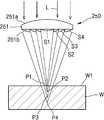
도 7은 본 발명의 또 다른 예시적인 실시예에 따른 레이저 가공장치를 개략적으로 도시한 것이다. 그리고, 도 8은 도 7에 도시된 레이저 가공장치에서 레이저 광이 집속 유닛을 통해 기판에 조사되는 모습을 도시한 것이다.7 schematically shows a laser processing apparatus according to another exemplary embodiment of the present invention. 8 shows a state in which laser light is irradiated onto the substrate through the focusing unit in the laser processing apparatus shown in Fig.
도 7 및 도 8을 참조하면, 레이저 가공장치(200)는 레이저 광(L)을 방출하는 레이저 광원(210)과, 레이저 광원(210)으로부터 출사된 레이저 광(L)을 집속하여 기판에 조사하는 집속 유닛(250)을 포함한다.7 and 8, the
레이저 광원(210)은 중심부에서 가장자리 부분으로 갈수록 그 세기(intensity)가 약해지는 가우시안(Gaussian) 형태의 세기를 가질 수 있다. 레이저 광원(210)과 집속 유닛(250) 사이에는 레이저 광원과 집속 유닛 사이에는 스캔 유닛(scan unit,230)이 마련될 수 있다. 한편, 레이저 광원(210)과 스캔 유닛(230) 사이에는 예를 들면 빔 확장유닛 등과 같은 소정 광학계(220)가 더 마련될 수도 있다.The
집속 유닛(250)은 입사된 레이저 광(L)을 집속하여 기판(W)에 복수의 집광점(P1,P2,P3,P4)을 형성시킬 수 있다. 이러한 집광점들(P1,P2,P3,P4)은 기판(W)의 두께 방향을 따라 일정한 간격으로 이격되게 배치되도록 형성될 수 있다. 집속 유닛은 전술한 바와 같이, 몸체부(251)와 이 몸체부(251)에 마련되는 서로 다른 곡률 반경을 가지는 복수의 렌즈부(S1,S2,S3,S4)를 포함한다.The focusing
몸체부(251)는 광이 입사되는 제1면(251a)과 이 제1면(251a)의 반대쪽에 위치하는 제2면(251b)을 포함할 수 있다. 여기서, 몸체부(251)의 제1면(251a)은 가우시안 형태의 세기를 가지는 레이저 광이 입사하는 면이다. 그리고, 몸체부(251)의 제2면(251b)은 제1면(251)으로부터 입사된 레이저 광(L)이 투과하는 면으로서 평탄한 형태를 가질 수 있다. 몸체부(251)의 평탄한 제2면(251b)에는 서로 다른 곡률반경을 가지는 복수의 렌즈부(S1,S2,S3,S4)가 마련되어 있다. 이러한 복수의 렌즈부(S1,S2,S3,S4)는 제1 렌즈부(S1)와 이 제1 렌즈부(S1)를 순차적으로 둘러싸도록 마련되는 제2, 제3 및 제4 렌즈부(S2,S3,S4)를 포함할 수 있다. 여기서, 제2, 제3 및 제4 렌즈부(S2,S3,S4)는 각각 제1 렌즈부(S1)로부터 멀어질수록 그 두께가 점점 얇아지는 형상을 가질 수 있다. 이러한 복수의 렌즈부(S1,S2,S3,S4)에 대해서는 전술하였으므로 이에 대한 상세한 설명은 생략한다.The
제1, 제2, 제3 및 제4 렌즈부(S1,S2,S3,S4)는 서로 다른 곡률 반경을 가질 수 있다. 예를 들면, 제1, 제2, 제3 및 제4 렌즈부(S1,S2,S3,S4)는 제1 렌즈부로부터 멀어질수록 큰 곡률 반경들을 가질 수 있다. 이와 같이, 집속 유닛을 구성하는 제1, 제2, 제3 및 제4 렌즈부(S1,S2,S3,S4)가 서로 다른 곡률 반경을 가짐으로써 도 8에 도시된 바와 같이 기판에는 기판의 두께 방향을 따라 서로 이격되게 배치되는 복수의 집광점(P1,P2,P3,P4)이 형성될 수 있다. 도 8에는 제1, 제2, 제3 및 제4 렌즈부(S1,S2,S3,S4)가 제1 렌즈부로부터 멀어질수록 큰 곡률 반경들을 가지는 경우에 형성될 수 있는 제1, 제2, 제3 및 제 4 집광점(P1,P2,P3,P4)이 도시되어 있다.The first, second, third, and fourth lens units S1, S2, S3, and S4 may have different radii of curvature. For example, the first, second, third, and fourth lens units S1, S2, S3, and S4 may have larger radius of curvature as they move away from the first lens unit. As described above, since the first, second, third, and fourth lens units S1, S2, S3, and S4 forming the focusing unit have different radii of curvature, A plurality of light-converging points P1, P2, P3, and P4 may be formed so as to be spaced apart from each other along the direction. 8 shows the first and second lens sections S1, S2, S3, and S4 which can be formed when the first, second, third, and fourth lens sections S1, S2, S3, , And third and fourth light-converging points P1, P2, P3, and P4.
본 실시예에서는 가운데 부분에서 가장 자리 부분으로 갈수록 그 세기가 약해지는 가우시안 형태의 세기를 가지는 레이저 광(L)이 집속 유닛(250)에 입사된다. 이에 따라, 제1 렌즈부(S1)에 가장 강한 세기의 광이 입사되며, 제4 렌즈부(S4)에 가장 약한 세기의 광이 입사될 수 있다. 이 경우, 제1, 제2, 제3 및 제4 렌즈부(S1,S2,S3,S4)가 제1 렌즈부(S1)로부터 멀어질수록 점점 큰 광 입사면적들을 가질 수 있다. 이와 같이, 제1, 제2, 제3 및 제4 렌즈부(S1,S2,S3,S4)가 점점 큰 광 입사면적을 가지도록 마련함으로써 기판(W)에 형성되는 제1, 제2, 제3 및 제4 집광점(P1,P2,P3,P4)에서의 에너지 밀도는 균일하게 될 수 있으며, 그 결과 기판(W)의 가공을 보다 용이하고 정밀하게 할 수 있다. 한편, 이상에서는 집속 유닛(250)이 4개의 렌즈부(S1,S2,S3,S4)를 포함하는 경우가 예시적으로 설명되었으나, 이에 한정되지 않고 렌즈부들(S1,S2,S3,S4)의 개수를 다양하게 변형할 수 있다.In the present embodiment, the laser beam L having a Gaussian intensity whose intensity decreases from the middle portion to the edge portion is incident on the focusing
이상에서 본 발명의 실시예가 설명되었으나, 이는 예시적인 것에 불과하며, 당해 분야에서 통상적 지식을 가진 자라면 이로부터 다양한 변형 및 균등한 타 실시예가 가능하다는 점을 이해할 것이다.While the invention has been shown and described with reference to certain preferred embodiments thereof, it will be understood by those skilled in the art that various changes and modifications may be made without departing from the scope of the invention as defined by the appended claims.
10.. 렌즈 광학계
11,151,251.. 몸체부
11a, 151a, 251a.. 몸체부의 제1면
11b, 151b, 251b.. 몸체부의 제2면
S1, S2, S3, S4.. 제1, 제2, 제3, 제4 렌즈부
L1, L2, L3, L4.. 제1, 제2, 제3 제4 레이저광
P1, P2, P3, P4.. 제1, 제2, 제3, 제4 집광점
W.. 기판
21, 22, 23, 24.. 제1, 제2, 제3, 제4 렌즈부재
50.. 스테이지
100,200.. 레이저 가공장치
110,210.. 레이저 광원
130,230.. 스캔 유닛
140.. 빔 성형유닛
150,250.. 집속 유닛10. Lens optical system
11,151,251.
11a, 151a, 251a. The first side of the body portion
11b, 151b, 251b. The second face
S1, S2, S3, S4. The first, second, third,
L1, L2, L3, L4. The first, second, and third fourth laser beams
P1, P2, P3, P4. The first, second, third, and fourth light-
W .. Substrate
21, 22, 23, 24. The first, second, third, and fourth lens elements
50 .. Stage
100,200 .. Laser processing equipment
110, 210 .. Laser light source
130, 230. The scan unit
140 .. beam forming unit
150,250 .. Focusing unit
Claims (21)
Translated fromKorean상기 제2면의 가운데에 위치하도록 마련되는 원형 렌즈부; 및
상기 제2면에 상기 원형 렌즈부를 둘러싸도록 마련되는 적어도 하나의 환형 렌즈부;를 포함하고,
상기 원형 렌즈부 및 상기 적어도 하나의 환형 렌즈부는 서로 다른 곡률 반경을 가짐으로써 상기 광의 진행 방향을 따라 이격되게 배치되는 복수의 집광점을 형성하는 렌즈 광학계.A body portion including a first surface on which light is incident and a second flat surface opposite to the first surface;
A circular lens portion provided at a center of the second surface; And
And at least one annular lens portion provided on the second surface so as to surround the circular lens portion,
Wherein the circular lens portion and the at least one annular lens portion have a different radius of curvature to form a plurality of light-converging points spaced apart along the traveling direction of the light.
상기 적어도 하나의 환형 렌즈부 각각은 상기 원형 렌즈부로부터 멀어질수록 두께가 점점 얇아지는 형상을 가지는 렌즈 광학계.The method according to claim 1,
Wherein each of the at least one annular lens portion has a shape in which a thickness becomes gradually thinner as the distance from the circular lens portion increases.
상기 원형 렌즈부는 상기 적어도 하나의 환형 렌즈부 각각 보다 작은 곡률 반경을 가지는 렌즈 광학계.The method according to claim 1,
Wherein the circular lens portion has a radius of curvature smaller than that of each of the at least one annular lens portion.
상기 적어도 하나의 환형 렌즈부는 상기 원형 렌즈부로부터 멀어질수록 점점큰 곡률 반경을 가지는 복수개의 환형 렌즈부를 포함하는 렌즈 광학계.The method of claim 3,
Wherein the at least one annular lens portion includes a plurality of annular lens portions having a gradually increasing radius of curvature from the circular lens portion.
상기 원형 렌즈부와 상기 적어도 하나의 환형 렌즈부 각각은 동일한 광 입사면적을 가지는 렌즈 광학계.The method according to claim 1,
Wherein the circular lens portion and the at least one annular lens portion each have the same light incidence area.
상기 원형 렌즈부는 상기 적어도 하나의 환형 렌즈부 각각 보다 작은 광 입사면적을 가지는 렌즈 광학계.The method according to claim 1,
Wherein the circular lens portion has a light incidence area smaller than that of each of the at least one annular lens portion.
상기 적어도 하나의 환형 렌즈부는 상기 원형 렌즈부로부터 멀어질수록 점점큰 광 입사면적으로 가지는 복수개의 환형 렌즈부를 포함하는 렌즈 광학계.The method according to claim 6,
Wherein the at least one annular lens portion includes a plurality of annular lens portions having a light incidence area which gradually increases with distance from the circular lens portion.
상기 몸체부의 제1면에는 가우시안 형태, 도그이어 타입 형태 또는 평탄한 형태의 세기(intensity)를 가지는 레이저 빔이 입사되는 렌즈 광학계.The method according to claim 1,
And a laser beam having an intensity of a Gaussian shape, a dogleg type, or a flat shape is incident on the first surface of the body part.
상기 레이저 광원으로부터 출사된 레이저 광을 집속하여 기판에 조사하는 집속 유닛(focusing unit);을 포함하고,
상기 집속 유닛은,
상기 레이저 광이 입사되는 제1면과, 상기 제1면의 반대쪽에 위치하는 평탄한 제2면을 포함하는 몸체부;
상기 제2면의 가운데에 위치하도록 마련되는 원형 렌즈부; 및
상기 제2면에 상기 원형 렌즈부를 둘러싸도록 마련되는 적어도 하나의 환형 렌즈부;를 포함하고,
상기 원형 렌즈부 및 상기 적어도 하나의 환형 렌즈부는 서로 다른 곡률 반경을 가짐으로써 상기 기판의 두께 방향을 따라 이격되게 배치되는 복수의 집광점을 형성하는 레이저 가공장치.A laser light source for emitting laser light; And
And a focusing unit for focusing the laser light emitted from the laser light source and irradiating the laser light onto the substrate,
The focusing unit includes:
A body portion including a first surface on which the laser light is incident and a second flat surface opposite to the first surface;
A circular lens portion provided at a center of the second surface; And
And at least one annular lens portion provided on the second surface so as to surround the circular lens portion,
Wherein the circular lens portion and the at least one annular lens portion have a different radius of curvature to form a plurality of light-converging points spaced apart along the thickness direction of the substrate.
상기 기판은 상기 레이저 광에 대해 투과성을 가지는 물질을 포함하는 레이저 가공장치.10. The method of claim 9,
Wherein the substrate comprises a material having transparency to the laser light.
상기 기판에 조사되는 상기 레이저 광을 가공 방향을 따라 주사하는 스캔 유닛을 더 포함하는 레이저 가공장치.10. The method of claim 9,
And a scanning unit for scanning the laser light irradiated to the substrate along a processing direction.
상기 적어도 하나의 환형 렌즈부 각각은 상기 원형 렌즈부로부터 멀어질수록 두께가 점점 얇아지는 형상을 가지는 레이저 가공장치.10. The method of claim 9,
Wherein each of the at least one annular lens portion has a shape in which the thickness becomes gradually thinner as the distance from the circular lens portion increases.
상기 원형 렌즈부는 상기 적어도 하나의 환형 렌즈부 각각 보다 작은 곡률 반경을 가지는 레이저 가공장치.10. The method of claim 9,
Wherein the circular lens portion has a radius of curvature smaller than that of each of the at least one annular lens portion.
상기 적어도 하나의 환형 렌즈부는 상기 원형 렌즈부로부터 멀어질수록 점점큰 곡률 반경을 가지는 복수개의 환형 렌즈부를 포함하는 레이저 가공장치.14. The method of claim 13,
Wherein the at least one annular lens portion includes a plurality of annular lens portions having a gradually increasing radius of curvature from the circular lens portion.
상기 레이저 광원은 가우시안 형태의 세기를 가지는 레이저 빔을 방출하는 레이저 가공장치.10. The method of claim 9,
Wherein the laser light source emits a laser beam having a Gaussian intensity.
상기 원형 렌즈부는 상기 적어도 하나의 환형 렌즈부 각각 보다 작은 광 입사면적을 가지는 레이저 가공장치.16. The method of claim 15,
Wherein the circular lens portion has a light incidence area smaller than that of each of the at least one annular lens portion.
상기 적어도 하나의 환형 렌즈부는 상기 원형 렌즈부로부터 멀어질수록 점점큰 광 입사면적으로 가지는 복수개의 환형 렌즈부를 포함하는 레이저 가공장치.17. The method of claim 16,
Wherein the at least one annular lens portion includes a plurality of annular lens portions each having a light incidence area gradually increasing away from the circular lens portion.
상기 레이저 광원과 상기 집속 유닛 사이에 마련되어 상기 레이저 광원으로부터 출사된 레이저 빔을 도그이어 타입 형태 또는 평탄한 형태의 세기를 가지도록 변형시키는 빔 성형 유닛을 더 포함하는 레이저 가공장치.10. The method of claim 9,
Further comprising a beam shaping unit provided between the laser light source and the focusing unit for deforming the laser beam emitted from the laser light source so as to have a dogleg type or a flat type intensity.
상기 원형 렌즈부와 상기 적어도 하나의 환형 렌즈부 각각은 동일한 광 입사면적을 가지는 레이저 가공장치.19. The method of claim 18,
Wherein the circular lens portion and the at least one annular lens portion each have the same light incidence area.
상기 렌즈 광학계는, 상기 레이저 광이 입사되는 제1면과 상기 제1면의 반대쪽에 위치하는 평탄한 제2면을 포함하는 몸체부와, 상기 제2면의 가운데에 위치하도록 마련되는 원형 렌즈부와, 상기 제2면에 상기 원형 렌즈부를 둘러싸도록 마련되는 적어도 하나의 환형 렌즈부;를 포함하고,
상기 원형 렌즈부 및 상기 적어도 하나의 환형 렌즈부는 서로 다른 곡률 반경을 가짐으로써 상기 레이저 광은 상기 렌즈 광학계에 의해 다중 집속되어 상기 기판의 두께 방향을 따라 서로 이격된 복수의 집광점을 형성하는 레이저 가공방법.A method of processing a substrate by focusing a laser beam using a lens optical system,
Wherein the lens optical system includes a body portion including a first surface on which the laser beam is incident and a second flat surface located on the opposite side of the first surface, a circular lens portion provided to be positioned at the center of the second surface, And at least one annular lens portion provided on the second surface so as to surround the circular lens portion,
Wherein the circular lens portion and the at least one annular lens portion have different radii of curvature so that the laser light is multi-focused by the lens optical system to form a plurality of light-converging points spaced apart from each other along the thickness direction of the substrate Way.
상기 기판은 상기 레이저 광에 대해 투과성을 가지는 물질을 포함함으로써 상기 복수의 집광점 중 적어도 하나는 상기 기판의 내부에 형성되는 레이저 가공방법.21. The method of claim 20,
Wherein the substrate includes a material having transparency to the laser light so that at least one of the plurality of light-converging points is formed inside the substrate.
Priority Applications (3)
| Application Number | Priority Date | Filing Date | Title |
|---|---|---|---|
| KR1020150187640AKR102046932B1 (en) | 2015-12-28 | 2015-12-28 | Lens optical system and laser processing apparatus |
| PCT/KR2016/009758WO2017115974A1 (en) | 2015-12-28 | 2016-09-01 | Lens optical system and laser processing apparatus comprising same |
| TW105129941ATWI626103B (en) | 2015-12-28 | 2016-09-14 | Lens optical system, laser processing apparatus, and laser processing method |
Applications Claiming Priority (1)
| Application Number | Priority Date | Filing Date | Title |
|---|---|---|---|
| KR1020150187640AKR102046932B1 (en) | 2015-12-28 | 2015-12-28 | Lens optical system and laser processing apparatus |
Publications (2)
| Publication Number | Publication Date |
|---|---|
| KR20170077597Atrue KR20170077597A (en) | 2017-07-06 |
| KR102046932B1 KR102046932B1 (en) | 2019-11-20 |
Family
ID=59225064
Family Applications (1)
| Application Number | Title | Priority Date | Filing Date |
|---|---|---|---|
| KR1020150187640AActiveKR102046932B1 (en) | 2015-12-28 | 2015-12-28 | Lens optical system and laser processing apparatus |
Country Status (3)
| Country | Link |
|---|---|
| KR (1) | KR102046932B1 (en) |
| TW (1) | TWI626103B (en) |
| WO (1) | WO2017115974A1 (en) |
Families Citing this family (4)
| Publication number | Priority date | Publication date | Assignee | Title |
|---|---|---|---|---|
| JP7420768B2 (en)* | 2021-07-01 | 2024-01-23 | フタバ産業株式会社 | Method for manufacturing tailored blanks and manufacturing method for automobile parts |
| CN113634930B (en)* | 2021-09-23 | 2023-01-31 | 山东理工大学 | Water-guiding laser water-optical coupling variable curvature focusing column lens |
| CN116460421A (en)* | 2023-05-24 | 2023-07-21 | 深圳公大激光有限公司 | Composite laser |
| CN116475564A (en)* | 2023-05-26 | 2023-07-25 | 深圳公大激光有限公司 | A compound laser and laser processing system |
Citations (3)
| Publication number | Priority date | Publication date | Assignee | Title |
|---|---|---|---|---|
| US6462891B1 (en)* | 2000-04-20 | 2002-10-08 | Raytheon Company | Shaping optic for diode light sheets |
| JP3339689B2 (en)* | 1996-05-23 | 2002-10-28 | アルコン ラボラトリーズ,インコーポレイテッド | Improved diffractive multifocal ophthalmic lens |
| JP2013101243A (en)* | 2011-11-09 | 2013-05-23 | Sigma Koki Kk | Multi-focal optical system and laser processing device |
Family Cites Families (8)
| Publication number | Priority date | Publication date | Assignee | Title |
|---|---|---|---|---|
| US4050782A (en)* | 1975-04-21 | 1977-09-27 | Nippon Electric Company, Ltd. | Mode separator and delay equalizer for multimode optical fiber transmission systems |
| JPS58119081A (en)* | 1982-01-07 | 1983-07-15 | Casio Comput Co Ltd | Scanner |
| JPS63299881A (en)* | 1987-05-30 | 1988-12-07 | Toshiba Corp | Condensing apparatus for laser beam |
| US7402773B2 (en)* | 2005-05-24 | 2008-07-22 | Disco Corporation | Laser beam processing machine |
| JP5286485B2 (en)* | 2008-11-18 | 2013-09-11 | 株式会社日立情報通信エンジニアリング | Laser processing apparatus and laser processing method |
| CN102109622B (en)* | 2009-12-28 | 2012-09-19 | 富士迈半导体精密工业(上海)有限公司 | condenser lens |
| TWM409433U (en)* | 2011-03-18 | 2011-08-11 | Probright Technology Inc | Optical display component with multiple focuses |
| KR101547806B1 (en)* | 2013-07-29 | 2015-08-27 | 에이피시스템 주식회사 | Device for processing brittle substrate using aspherical lens having multi focus |
- 2015
- 2015-12-28KRKR1020150187640Apatent/KR102046932B1/enactiveActive
- 2016
- 2016-09-01WOPCT/KR2016/009758patent/WO2017115974A1/ennot_activeCeased
- 2016-09-14TWTW105129941Apatent/TWI626103B/ennot_activeIP Right Cessation
Patent Citations (3)
| Publication number | Priority date | Publication date | Assignee | Title |
|---|---|---|---|---|
| JP3339689B2 (en)* | 1996-05-23 | 2002-10-28 | アルコン ラボラトリーズ,インコーポレイテッド | Improved diffractive multifocal ophthalmic lens |
| US6462891B1 (en)* | 2000-04-20 | 2002-10-08 | Raytheon Company | Shaping optic for diode light sheets |
| JP2013101243A (en)* | 2011-11-09 | 2013-05-23 | Sigma Koki Kk | Multi-focal optical system and laser processing device |
Also Published As
| Publication number | Publication date |
|---|---|
| KR102046932B1 (en) | 2019-11-20 |
| TWI626103B (en) | 2018-06-11 |
| TW201722600A (en) | 2017-07-01 |
| WO2017115974A1 (en) | 2017-07-06 |
Similar Documents
| Publication | Publication Date | Title |
|---|---|---|
| US8466074B2 (en) | Method for processing a substrate using a laser beam | |
| US11931827B2 (en) | Laser cutting device and laser cutting method | |
| CN109641315B (en) | Multi-zone focusing lens and laser processing system for wafer dicing or cutting | |
| CN107214420B (en) | Method and device for processing wafer by laser | |
| KR101774290B1 (en) | Method and apparatus of processing brittle material with laser pin beam and optical system for the same | |
| KR20170028426A (en) | Method and device for the laser-based working of two-dimensional, crystalline substrates, in particular semiconductor substrates | |
| KR101655428B1 (en) | Optical apparus using bessel beam and cutting apparatus thereof | |
| KR20140137437A (en) | Laser scribing with extended depth affectation into a workpiece | |
| KR101547806B1 (en) | Device for processing brittle substrate using aspherical lens having multi focus | |
| KR102046932B1 (en) | Lens optical system and laser processing apparatus | |
| US11000919B2 (en) | Laser processing apparatus | |
| CN110753596B (en) | Device and method for laser-based separation of transparent and fragile workpieces | |
| WO2018011618A1 (en) | Method and system for cleaving a substrate with a focused converging ring-shaped laser beam | |
| TW201714694A (en) | Laser processing method and laser processing apparatus using multi focusing | |
| CN110961780B (en) | Laser processing apparatus | |
| WO2015098388A1 (en) | Processing device | |
| KR20130033114A (en) | Laser processing method | |
| CN109683235B (en) | A multi-layer optical fiber and a laser system for realizing dual laser output | |
| US20190129188A1 (en) | F-theta lens and laser apparatus including the f-theta lens | |
| KR20210125361A (en) | Laser processing appartus for quartz ware and laser processing method for quartz ware | |
| CN104526160B (en) | A kind of laser processing and laser-processing system | |
| JP2007136481A (en) | Laser beam machining device | |
| US20100053739A1 (en) | Laser device providing an adjusted field distribution for laser beams thereof | |
| TWI715848B (en) | Optical element having microstructure to form cylindrical beam | |
| KR20130112111A (en) | Laser processing method |
Legal Events
| Date | Code | Title | Description |
|---|---|---|---|
| A201 | Request for examination | ||
| PA0109 | Patent application | Patent event code:PA01091R01D Comment text:Patent Application Patent event date:20151228 | |
| PA0201 | Request for examination | ||
| PG1501 | Laying open of application | ||
| E902 | Notification of reason for refusal | ||
| PE0902 | Notice of grounds for rejection | Comment text:Notification of reason for refusal Patent event date:20170830 Patent event code:PE09021S01D | |
| E601 | Decision to refuse application | ||
| PE0601 | Decision on rejection of patent | Patent event date:20180419 Comment text:Decision to Refuse Application Patent event code:PE06012S01D Patent event date:20170830 Comment text:Notification of reason for refusal Patent event code:PE06011S01I | |
| J201 | Request for trial against refusal decision | ||
| PJ0201 | Trial against decision of rejection | Patent event date:20180619 Comment text:Request for Trial against Decision on Refusal Patent event code:PJ02012R01D Patent event date:20180419 Comment text:Decision to Refuse Application Patent event code:PJ02011S01I Appeal kind category:Appeal against decision to decline refusal Appeal identifier:2018101002572 Request date:20180619 | |
| J301 | Trial decision | Free format text:TRIAL NUMBER: 2018101002572; TRIAL DECISION FOR APPEAL AGAINST DECISION TO DECLINE REFUSAL REQUESTED 20180619 Effective date:20191014 | |
| PJ1301 | Trial decision | Patent event code:PJ13011S01D Patent event date:20191014 Comment text:Trial Decision on Objection to Decision on Refusal Appeal kind category:Appeal against decision to decline refusal Request date:20180619 Decision date:20191014 Appeal identifier:2018101002572 | |
| PS0901 | Examination by remand of revocation | ||
| S901 | Examination by remand of revocation | ||
| GRNO | Decision to grant (after opposition) | ||
| PS0701 | Decision of registration after remand of revocation | Patent event date:20191111 Patent event code:PS07012S01D Comment text:Decision to Grant Registration Patent event date:20191015 Patent event code:PS07011S01I Comment text:Notice of Trial Decision (Remand of Revocation) | |
| GRNT | Written decision to grant | ||
| PR0701 | Registration of establishment | Comment text:Registration of Establishment Patent event date:20191114 Patent event code:PR07011E01D | |
| PR1002 | Payment of registration fee | Payment date:20191115 End annual number:3 Start annual number:1 | |
| PG1601 | Publication of registration | ||
| PR1001 | Payment of annual fee | Payment date:20221115 Start annual number:4 End annual number:4 | |
| PR1001 | Payment of annual fee | Payment date:20231115 Start annual number:5 End annual number:5 |