KR20170076544A - Electronic device and method for controlling the electronic device - Google Patents
Electronic device and method for controlling the electronic deviceDownload PDFInfo
- Publication number
- KR20170076544A KR20170076544AKR1020160147636AKR20160147636AKR20170076544AKR 20170076544 AKR20170076544 AKR 20170076544AKR 1020160147636 AKR1020160147636 AKR 1020160147636AKR 20160147636 AKR20160147636 AKR 20160147636AKR 20170076544 AKR20170076544 AKR 20170076544A
- Authority
- KR
- South Korea
- Prior art keywords
- user
- virtual reality
- hand
- coordinates
- motion detector
- Prior art date
- Legal status (The legal status is an assumption and is not a legal conclusion. Google has not performed a legal analysis and makes no representation as to the accuracy of the status listed.)
- Granted
Links
Images


Classifications
- G—PHYSICS
- G06—COMPUTING OR CALCULATING; COUNTING
- G06F—ELECTRIC DIGITAL DATA PROCESSING
- G06F3/00—Input arrangements for transferring data to be processed into a form capable of being handled by the computer; Output arrangements for transferring data from processing unit to output unit, e.g. interface arrangements
- G06F3/01—Input arrangements or combined input and output arrangements for interaction between user and computer
- G06F3/017—Gesture based interaction, e.g. based on a set of recognized hand gestures
- G—PHYSICS
- G06—COMPUTING OR CALCULATING; COUNTING
- G06F—ELECTRIC DIGITAL DATA PROCESSING
- G06F3/00—Input arrangements for transferring data to be processed into a form capable of being handled by the computer; Output arrangements for transferring data from processing unit to output unit, e.g. interface arrangements
- G06F3/01—Input arrangements or combined input and output arrangements for interaction between user and computer
- G06F3/011—Arrangements for interaction with the human body, e.g. for user immersion in virtual reality
- G06F3/012—Head tracking input arrangements
- G—PHYSICS
- G06—COMPUTING OR CALCULATING; COUNTING
- G06F—ELECTRIC DIGITAL DATA PROCESSING
- G06F3/00—Input arrangements for transferring data to be processed into a form capable of being handled by the computer; Output arrangements for transferring data from processing unit to output unit, e.g. interface arrangements
- G06F3/01—Input arrangements or combined input and output arrangements for interaction between user and computer
- G06F3/011—Arrangements for interaction with the human body, e.g. for user immersion in virtual reality
- G06F3/014—Hand-worn input/output arrangements, e.g. data gloves
Landscapes
- Engineering & Computer Science (AREA)
- General Engineering & Computer Science (AREA)
- Theoretical Computer Science (AREA)
- Human Computer Interaction (AREA)
- Physics & Mathematics (AREA)
- General Physics & Mathematics (AREA)
- User Interface Of Digital Computer (AREA)
Abstract
Translated fromKorean
Description
Translated fromKorean전자 장치 및 제어 방법에 관한 것이다.To an electronic apparatus and a control method.
최근 가상 현실 장치(Virtual Reality Device)를 이용하여 사용자에게 이미지를 제공하는 장치들이 개발되고 있다. 가상 현실 기술은 조작된 감각 자극을 통해 사용자가 현실감을 느끼도록 하는 것으로 게임, 교육, 의료, 저널리즘 등 많은 산업 영역에서 활용될 수 있다.Recently, devices for providing images to users by using a virtual reality device have been developed. Virtual reality technology enables users to feel reality through manipulated sensory stimulation and can be used in many industrial fields such as games, education, medical care, journalism.
기존의 평판 디스플레이에서 정해진 크기의 화면만 보여주던 것과는 다르게, 가상 현실 장치를 이용하여 360도 시야 전체가 가득차는 것을 경험할 수 있게 된다. 이를 통해 사용자는 마치 다른 세상으로 이동한듯한 몰입감을 느끼게 된다. 가상 현실 기술은 사용자에게 시각, 청각 등의 감각을 제공하는 것 이외에도 촉감을 느끼게 하여 몰입감을 향상시킨다.Unlike a conventional flat panel display in which only a screen of a predetermined size is displayed, it is possible to experience a full 360-degree field of view using a virtual reality apparatus. This allows the user to feel immersive as if they were moving to another world. Virtual reality technology not only provides the user with a sense of sight, hearing, etc., but also enhances immersion by making the user feel tactile.
전자 장치 및 제어 방법을 제공하고자 한다. 또한, 상기 방법을 컴퓨터에서 실행시키기 위한 프로그램을 기록한 컴퓨터로 읽을 수 있는 기록 매체를 제공하고자 한다. 본 실시예가 이루고자 하는 기술적 과제는 상기된 바와 같은 기술적 과제들로 한정되지 않으며, 이하의 실시예들로부터 또 다른 기술적 과제들이 유추될 수 있다.An electronic device, and a control method. Also, a computer-readable recording medium on which a program for causing the computer to execute the above method is provided. The technical problem to be solved by this embodiment is not limited to the above-mentioned technical problems, and other technical problems can be deduced from the following embodiments.
다양한 실시예에 따른 전자 장치는 자기장을 발생하는 소스; 발생된 자기장에 기초하여, 사용자의 손의 좌표를 획득하는 모션 검출기(motion detector); 및 모션 검출기로부터 수신한 사용자의 손의 좌표를 사용자의 움직임에 따른 소스의 위치 변화에 기초하여 가상 현실에 반영하는 가상 현실 제공 장치;를 포함할 수 있다.An electronic device according to various embodiments includes a source for generating a magnetic field; A motion detector for obtaining coordinates of a user's hand based on the generated magnetic field; And a virtual reality providing device for reflecting the coordinates of the hand of the user received from the motion detector to the virtual reality based on a change in the position of the source in accordance with the movement of the user.
다양한 실시예에 따른 전자 장치를 제어하는 방법은, 소스에서 발생된 자기장에 기초하여, 사용자의 손의 좌표를 획득하는 단계; 사용자의 움직임에 따른 소스의 위치 변화를 감지하는 단계; 및 획득한 사용자의 손의 좌표를 감지된 소스의 위치 변화에 기초하여 가상 현실에 반영하는 단계;를 포함할 수 있다.A method of controlling an electronic device according to various embodiments includes obtaining coordinates of a user's hand based on a magnetic field generated at a source; Detecting a change in the position of the source in accordance with the movement of the user; And reflecting the coordinates of the obtained hand of the user to the virtual reality based on the change in the position of the detected source.
다양한 실시예에 따른 모션 검출기는 사용자의 손의 움직임 정보, 모션 검출기의 종류, 모션 검출기에 결합된 액세서리의 종류, 모션 검출기의 동작 상태, 및 버튼 누름 정보 중 적어도 하나를 포함하는 모션 데이터를 획득하는 제어부; 및 사용자의 움직임을 반영한 가상 현실을 생성하는 가상 현실 제공 장치에 획득된 모션 데이터를 전송하는 통신 인터페이스;를 포함할 수 있다.The motion detector according to various embodiments obtains motion data including at least one of motion information of the user's hand, kind of motion detector, type of accessory coupled to the motion detector, operating state of the motion detector, and button press information A control unit; And a communication interface for transmitting the acquired motion data to the virtual reality providing device that generates the virtual reality reflecting the motion of the user.
도 1은 일 실시예에 따른 전자 장치의 구성을 설명하기 위한 블록도이다.
도 2는 일 실시예에 따른 전자 장치의 동작을 설명하기 위한 도면이다.
도 3은 다른 실시 예에 따른 전자 장치의 동작을 설명하기 위한 도면이다.
도 4는 일 실시예에 따른 가상 현실 제공 장치의 구성을 설명하기 위한 블록도이다.
도 5는 일 실시예에 따른 소스(source)의 구성을 설명하기 위한 블록도이다.
도 6은 일 실시예에 따른 모션 검출기(motion detector)의 구성을 설명하기 위한 블록도이다.
도 7은 일 실시예에 따른 전자 장치를 제어하는 방법을 설명하기 위한 도면이다.
도 8은 사용자의 머리 움직임을 보정하기 위한 연산을 설명하기 위한 도면이다.
도 9는 일 실시예에 따라 손가락 움직임 정보를 반영하는 전자 장치를 제어하는 방법을 설명하기 위한 도면이다.
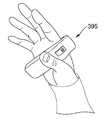
도 10은 일 실시예에 따른 모션 검출기의 형태를 설명하기 위한 도면이다.
도 11은 일 실시예에 따른 모션 검출기의 센서부의 배치를 설명하기 위한 도면이다.
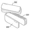
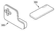
도 12a 내지 도 12d는 다양한 실시예에 따른 모션 검출기에 결합 가능한 액세서리를 설명하기 위한 도면이다.
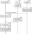
도 13은 일 실시예에 따라 전자 장치를 제어하는 방법을 설명하기 위한 흐름도이다.
도 14는 일 실시예에 따라 전자 장치를 제어하는 방법에 있어 가상 현실을 제공하는 과정을 설명하기 위한 흐름도이다.
도 15는 일 실시예에 따라 모션 검출기에서 진동이 발생하는 과정을 설명하기 위한 흐름도이다.
도 16은 일 실시예에 따라 모션 검출기에서 생성하는 모션 데이터의 필드를 설명하기 위한 도면이다.
도 17은 일 실시예에 따라 모션 검출기에서 생성하는 모션 데이터의 필드에 대하여 구체적으로 설명하기 위한 도면이다.1 is a block diagram for explaining a configuration of an electronic device according to an embodiment.
2 is a diagram for explaining the operation of the electronic device according to one embodiment.
3 is a diagram for explaining the operation of the electronic device according to another embodiment.
4 is a block diagram illustrating a configuration of a virtual reality providing apparatus according to an embodiment.
5 is a block diagram illustrating a configuration of a source according to an embodiment.
6 is a block diagram illustrating a configuration of a motion detector according to an embodiment.
7 is a diagram for explaining a method of controlling an electronic device according to an embodiment.
8 is a diagram for explaining an operation for correcting the head movement of the user.
9 is a diagram for explaining a method of controlling an electronic device reflecting finger motion information according to an embodiment.
10 is a view for explaining a form of a motion detector according to an embodiment.
11 is a view for explaining the arrangement of the sensor unit of the motion detector according to the embodiment.
12A-12D illustrate an accessory attachable to a motion detector in accordance with various embodiments.
13 is a flowchart illustrating a method of controlling an electronic device according to an embodiment.
14 is a flowchart illustrating a process of providing a virtual reality in a method of controlling an electronic device according to an embodiment.
15 is a flowchart illustrating a process of generating vibration in the motion detector according to an embodiment.
16 is a diagram for explaining fields of motion data generated by a motion detector according to an embodiment.
FIG. 17 is a diagram for specifically explaining fields of motion data generated by a motion detector according to an embodiment.
이하 첨부된 도면을 참조하여 예시적인 실시예에 의해 발명을 상세히 설명하기로 한다. 하기 실시예는 발명을 구체화하기 위한 것일 뿐 발명의 권리 범위를 제한하거나 한정하는 것이 아니다. 상세한 설명 및 실시예로부터 발명이 속하는 기술분야의 전문가가 용이하게 유추할 수 있는 것은 발명의 권리범위에 속하는 것으로 해석된다.DETAILED DESCRIPTION OF THE PREFERRED EMBODIMENTS The present invention will now be described in detail with reference to the accompanying drawings. The following examples are intended to illustrate the invention and are not intended to limit or limit the scope of the invention. It will be understood by those of ordinary skill in the art that various changes in form and details may be made therein without departing from the spirit and scope of the invention as defined by the appended claims.
또한, 단수의 표현은 문맥상 명백하게 단수를 뜻하지 않는 한, 복수의 의미를 포함한다.Also, the singular expressions include plural meanings unless the context clearly dictates singular.
본 명세서(특히, 특허 청구 범위에서)에서 사용된 “상기” 및 이와 유사한 지시어는 단수 및 복수 모두를 지시하는 것일 수 있다. 또한, 본 개시에 따른 방법을 설명하는 단계들의 순서를 명백하게 지정하는 기재가 없다면, 기재된 단계들은 적당한 순서로 행해질 수 있다. 기재된 단계들의 기재 순서에 따라 본 개시가 한정되는 것은 아니다.The " above " and similar indications used in this specification (especially in the claims) may refer to both singular and plural. Further, if there is no description explicitly specifying the order of the steps describing the method according to the present disclosure, the steps described may be performed in any suitable order. The present disclosure is not limited by the order of description of the steps described.
본 명세서에서 다양한 곳에 등장하는 "일 실시예에서" 등의 어구는 반드시 모두 동일한 실시예를 가리키는 것은 아니다.The phrases such as "in one embodiment" appearing in various places in this specification are not necessarily all referring to the same embodiment.
본 개시의 일부 실시예는 기능적인 블록 구성들 및 다양한 처리 단계들로 나타내어질 수 있다. 이러한 기능 블록들의 일부 또는 전부는, 특정 기능들을 실행하는 다양한 개수의 하드웨어 및/또는 소프트웨어 구성들로 구현될 수 있다.Some embodiments of the present disclosure may be represented by functional block configurations and various processing steps. Some or all of these functional blocks may be implemented with various numbers of hardware and / or software configurations that perform particular functions.
또한, 도면에 도시된 구성 요소들 간의 연결 선 또는 연결 부재들은 기능적인 연결 및/또는 물리적 또는 회로적 연결들을 예시적으로 나타낸 것일 뿐이다. 실제 장치에서는 대체 가능하거나 추가된 다양한 기능적인 연결, 물리적인 연결, 또는 회로 연결들에 의해 구성 요소들 간의 연결이 나타내어질 수 있다.Also, the connection lines or connection members between the components shown in the figures are merely illustrative of functional connections and / or physical or circuit connections. In practical devices, connections between components can be represented by various functional connections, physical connections, or circuit connections that can be replaced or added.
본 실시예들은 전자 장치 및 제어 방법에 관한 것으로서 이하의 실시예들이 속하는 기술 분야에서 통상의 지식을 가진 자에게 널리 알려져 있는 사항들에 관해서는 자세한 설명을 생략한다. 이하 첨부된 도면을 참조하여 본 개시를 상세히 설명하기로 한다.These embodiments relate to an electronic device and a control method, and a detailed description thereof will be omitted with respect to matters widely known to those skilled in the art to which the following embodiments belong. The present disclosure will be described in detail below with reference to the accompanying drawings.
도 1은 일 실시예에 따른 전자 장치(1000)의 구성을 설명하기 위한 도면이다. 도 1에 도시된 바와 같이, 전자 장치(1000)는 가상 현실 제공 장치(100), 소스(200), 모션 검출기(300)를 포함할 수 있다.1 is a diagram for explaining a configuration of an
소스(200)는 가상 현실 제공 장치(100)에 탈부착 가능하고, 가상 현실 제공 장치(100)는 사용자가 지닐 수 있거나 웨어러블(wearable)하다. 일 실시예에서, 소스(200)는 가상 현실 제공 장치(100)에 고정되거나 부착되어 물리적으로 근접할 뿐, 연동되지는 않는 반면에, 가상 현실 제공 장치(100)와 모션 검출기(300)는 통신 인터페이스들(110, 310)을 통해 무선 또는 유선으로 연결되어 데이터를 송수신할 수 있다.The
일 실시예에 따르면, 소스(200)는 가상 현실 제공 장치(100)에 부착된 별도의 장치 형태가 아니라, 가상 현실 제공 장치(100)에 포함될 수 있으며, 소스(200)에서 수행되는 동작들이 가상 현실 제공 장치(100)에서 수행될 수 있다.According to one embodiment, the
일 실시예에 따르면, 소스(200)는 가상 현실 제공 장치(100)에서 탈착될 수 있으며, 예를 들어, 사용자가 목걸이 형태로 소스(200)를 착용할 수 있다. 본 실시예에서, 소스(200)는 디스플레이하는 동작을 제외하고는, 가상 현실 제공 장치(100)가 수행하는 동작들을 수행할 수 있다. 본 실시예에서는 사용자가 소스(200)를 목걸이 형태로 착용하는 실시예에 대해 설명하였으나, 이에 제한되지 않고, 다양한 위치에 소스(200)를 위치시킬 수 있다.According to one embodiment, the
일 실시예에서, 가상 현실 제공 장치(100)와 모션 검출기(300)는 블루투스와 같은 무선 통신 방식으로 연결되고, 하기와 같은 예시의 초기 연결이 이루어질 수 있다. 초기 연결은 가상 현실 제공 장치(100)에서 블루투스를 통해 주변 기기를 검색하여 모션 검출기(300)와 페어링(pairing) 연결을 하거나, 모션 검출기(300)에 장착된 NFC를 통해 가상 현실 제공 장치(100)의 특정 부위에 모션 검출기(300)가 인식될 경우 자동으로 페어링 연결이 이루어질 수 있다. 초기 연결이 이루어진 후에는, 가상 현실 제공 장치(100)가 실행되면, 모션 검출기(300)의 전원이 켜질 때마다 연결을 시도하여, 사용자는 곧바로 모션 검출기(300)를 사용할 수 있다.In one embodiment, the virtual
일 실시예에서, 가상 현실 제공 장치(100)는 사용자가 있는 공간과 다른 공간인 가상 현실의 동영상 또는 이미지를 사용자에게 제공할 수 있다. 예를 들어, 사용자는 실내에서 가상 현실 제공 장치(100)를 이용하여 외국의 도시의 동영상 또는 이미지를 볼 수 있다. 예를 들어, 동영상을 재생하는 동안에, 사용자는 몸 전체를 움직이거나, 머리만 움직일 수 있다. 일 실시예에서, 가상 현실 제공 장치(100)는 사용자의 몸 전체가 움직이면 사용자의 이동 방향에 따라 이미지의 크기를 조절할 수 있다. 또한, 일 실시예에서, 가상 현실 제공 장치(100)는 사용자의 머리가 움직이면 사용자의 머리의 이동 및/또는 회전 방향에 따라 다른 동영상 또는 이미지를 제공할 수 있다.In one embodiment, the virtual
일 실시예에서, 가상 현실 제공 장치(100)는 사용자가 있는 현실 세계에 가상 현실을 오버랩(overlap)하여 디스플레이하는 증강 현실(Augmented reality)을 제공할 수 있다. 예를 들어, 가상 현실 제공 장치(100)는 사용자의 실제 손과 함께 모션 검출기에 결합된 액세서리의 종류에 기초한 오브젝트(object)를 디스플레이할 수 있다. 예를 들어, 사용자가 총 모양의 액세서리와 결합된 모션 검출기를 손에 착용하고 있는 경우, 가상 현실 제공 장치(100)는 실제 사용자의 손이 총 모양의 오브젝트를 쥐고 있는 증강 현실을 제공할 수 있다.In one embodiment, the virtual
가상 현실 제공 장치(100)는 헤드 마운트 디스플레이(Head Mounnted Display), VR 헤드셋(headset), 가상 현실 장치, PC(Personal Computer), 랩탑(laptop), 스마트 TV, 휴대폰, PDA, 스마트 단말기, 또는 게임기 등일 수 있으나 이에 제한되지 않는다. 또한, 가상 현실 제공 장치(100)는 통신 기능 및 데이터 프로세싱 기능을 구비한 안경, 헤어 밴드, 시계등일 수 있다.The virtual
모션 검출기(300)는 사용자가 손에 들고 이용하는 핸드헬드(handheld) 형태 또는 손바닥 부위에 착용하는 웨어러블(wearable)한 형태 일 수 있다. 모션 검출기(300)는 왼손용과 오른손용으로 구성될 수 있으며, 개별적으로도 이용이 가능하고, 동시에 이용될 수도 있다.The
도 2는 일 실시예에 따른 전자 장치(1000)의 동작을 설명하기 위한 도면이다. 도 2를 참조하여, 일 실시예에 따른 가상 현실 제공 장치(100)는 헤드 마운트 디스플레이(Head Mounnted Display), VR 헤드셋(headset), 가상 현실 장치 등 사용자의 머리에 착용하는 형태로 제작되어 사용자에게 360도 컨텐츠를 디스플레이하는 디바이스일 수 있다.2 is a diagram for explaining the operation of the
일 실시예에서, 가상 현실 제공 장치(100)는 사용자의 몸 전체가 움직이면 사용자의 이동 방향에 따라 동영상 또는 이미지의 크기를 조절할 수 있고, 사용자의 머리가 움직이면 사용자의 머리의 이동 및 회전 방향에 따라 다른 동영상 또는 이미지를 디스플레이할 수 있다.In one embodiment, the virtual
또한, 일 실시예에서, 가상 현실 제공 장치(100)는 가상 현실 제공 장치(100)가 제공하는 컨텐츠 또는 모션 검출기(300)의 종류에 따라 실제 사용자의 손의 위치와 각도에 부합하게 손이나 다른 형상의 유저 인터페이스(user interface)를 동영상 또는 이미지와 함께 디스플레이할 수 있다.In addition, in one embodiment, the virtual
도 3은 다른 실시예에 따른 전자 장치(1000)의 동작을 설명하기 위한 도면이다. 일 실시예에 따른 가상 현실 제공 장치(100)는 PC(Personal Computer), 랩탑(laptop), 스마트 TV, 휴대폰, PDA, 스마트 단말기, 또는 게임기 등일 수 있다.3 is a diagram for explaining the operation of the
일 실시예에서, 가상 현실 제공 장치(100)는 외부 디스플레이 장치(400)에 가상 현실을 제공할 수 있으며, 외부 디스플레이 장치(400)를 통하여 가상 현실이 디스플레이될 수 있다. 일 실시예에서, 가상 현실 제공 장치(100)는 외부 디스플레이 장치(400)와 유선 또는 무선의 통신 인터페이스(110)로 연결될 수 있고, 가상 현실 제공 장치(100)에 디스플레이된 스크린을 외부 디스플레이 장치(400)에서 동일하게 디스플레이할 수 있다. 일 실시예에서, 외부 디스플레이 장치(400)는 평판 디스플레이 장치 또는 곡면(curved) 디스플레이 장치일 수 있고, 가상 현실은 360도로 제공되지 않을 수 있다.In one embodiment, the virtual
또한, 일 실시예에서, 가상 현실 제공 장치(100)는 가상 현실 제공 장치(100)가 제공하는 컨텐츠 또는 모션 검출기(300)의 종류에 따라 실제 사용자의 손의 위치와 각도에 부합하게 손이나 다른 형상의 UI를 동영상 또는 이미지과 함께 디스플레이 하도록 외부 디스플레이 장치(400)를 제어할 수 있다.In addition, in one embodiment, the virtual
도 4는 일 실시예에 따른 가상 현실 제공 장치(100)의 구성을 설명하기 위한 블록도이다. 도 4에 도시된 바와 같이, 가상 현실 제공 장치(100)는, 통신 인터페이스(110), 센서부(120), 제어부(130), 디스플레이부(140)를 포함할 수 있다.FIG. 4 is a block diagram illustrating a configuration of a virtual
통신 인터페이스(110)는 다양한 종류의 통신 방식에 따라 다양한 유형의 외부 장치와 통신을 수행할 수 있다. 일 실시예에서, 통신 인터페이스(110)는 블루투스 칩, 와이파이 칩, 이동통신용 칩, 지그비(Zigbee) 칩, NFC(Near Field Communication) 칩, 적외선 통신 칩 등 다양한 종류의 무선 통신 칩 중 적어도 하나를 포함할 수 있다. 예를 들어, 블루투스 칩, 와이파이 칩은 각각 블루투스 방식, WiFi 방식으로 통신을 수행할 수 있다. 예를 들어, 블루투스 칩이나 와이파이 칩을 이용하는 경우에는 SSID 및 세션 키 등과 같은 각종 연결 정보를 먼저 송수신하여, 이를 이용하여 통신 연결한 후 각종 정보들을 송수신할 수 있다.The
일 실시예에서, 블루투스 칩은 블루투스4.0(BLE) 프로토콜 기반의 근거리 무선통신을 지원할 수 있다. 이동통신용 칩은 3G(3rd Generation), 3GPP(3rd Generation Partnership Project), LTE(Long Term Evoloution) 등과 같은 다양한 통신 규격에 따라 통신을 수행하는 칩을 의미한다. 지그비 칩은 IEEE 802.15.4 표준 중 하나에 해당하는 근거리 무선통신을 지원하며, 20 미터 내외의 거리에 있는 디바이스들 간의 데이터 저속 전송에 이용될 수 있다. NFC 칩은 다양한 RF-ID 주파수 대역들 중에서 13.56MHz 대역을 사용하는 근거리 무선통신 방식으로 동작하는 칩을 의미한다.In one embodiment, the Bluetooth chip may support near field wireless communication based on the Bluetooth 4.0 (BLE) protocol. The mobile communication chip refers to a chip that performs communication according to various communication standards such as 3G (3rd Generation), 3rd Generation Partnership Project (3GPP), and Long Term Evolution (LTE). The ZigBee chip supports short-range wireless communication corresponding to one of the IEEE 802.15.4 standards and can be used for low-speed data transmission between devices at distances of around 20 meters. The NFC chip refers to a chip operating in a short-range wireless communication system using the 13.56 MHz band among various RF-ID frequency bands.
또한, 통신 인터페이스(110)를 통해 가상 현실 제공 장치(100)는 모션 검출기(300)와 무선 또는 유선으로 연결되어 데이터를 송수신할 수 있다. 통신 인터페이스(110)는, 네트워크를 통해 연결될 수 있으며, 네트워크는, 근거리 통신망(Local Area Network; LAN), 광역 통신망(Wide Area Network; WAN) 또는 부가가치 통신망(Value Added Network; VAN) 등과 같은 유선 네트워크나 이동 통신망(mobile radio communication network) 또는 위성 통신망 등과 같은 모든 종류의 무선 통신 인터페이스(110)로 구현될 수 있다.In addition, the virtual
센서부(120)는, 센서들을 통해 사용자의 움직임을 감지하고, 감지된 정보를 제어부(130)로 전송할 수 있다. 센서부(120)는, 자기장 센서(Magnetic sensor), 자이로스코프 센서, 가속도 센서(Acceleration sensor), 광 센서, 카메라 센서, 초음파 센서, 적외선 센서, 온/습도 센서, 위치 센서, 기압 센서, 근접 센서, 및 RGB 센서(illuminance sensor) 중 적어도 하나를 포함할 수 있으나, 이에 제한되지 않는다. 각 센서들의 기능은 그 명칭으로부터 당업자가 직관적으로 추론할 수 있으므로, 구체적인 설명은 생략하기로 한다.The
제어부(130)는 가상 현실 제공 장치(100)의 전반적인 제어를 수행할 수 있다. 제어부(130)는 적어도 하나의 프로세서를 구비할 수 있다. 제어부(130)는 그 기능 및 역할에 따라, 복수의 프로세서들을 포함하거나, 통합된 형태의 하나의 프로세서를 포함할 수 있다.The
제어부(130)는 통신 인터페이스(110)를 이용하여, 외부 기기들과 통신을 수행할 수 있다. 또한, 제어부(130)는 유저 인터페이스를 통한 사용자 조작이 이루어지면, 사용자의 조작에 대응되는 제어 동작을 수행할 수 있다. The
제어부(130)는 RAM, ROM, CPU, GPU(Graphic Processing Unit) 및 데이터버스 중 적어도 하나를 포함할 수 있다. RAM, ROM, CPU, 및 GPU 등은 데이터버스를 통해 서로 연결될 수 있다. CPU는 메모리(미도시)에 액세스(access)하여, 메모리(미도시)에 저장된 O/S를 이용하여 부팅을 수행한다. 그리고, 메모리(미도시)에 저장된 각종 프로그램, 컨텐츠, 데이터 등을 이용하여 다양한 동작을 수행한다. ROM에는 시스템 부팅을 위한 명령어 세트 등이 저장된다. 예를 들면, 가상 현실 제공 장치(100)는 턴온(turn on) 명령이 입력되어 전원이 공급되면, CPU가 ROM에 저장된 명령어에 따라 메모리에 저장된 O/S를 RAM에 복사하고, O/S를 실행시켜 시스템을 부팅시킬 수 있다. 부팅이 완료되면, CPU는 메모리(미도시)에 저장된 각종 프로그램을 RAM에 복사하고, RAM에 복사된 프로그램을 실행시켜 각종 동작을 수행한다. GPU는 가상 현실 제공 장치(100)의 부팅이 완료되면, 디스플레이(140)에 스크린을 디스플레이한다.The
일 실시예에서, GPU는 컨텐츠, 아이콘, 메뉴 등과 같은 다양한 객체를 포함하는 전자문서가 표시된 스크린을 생성할 수 있다. GPU는 스크린의 레이아웃에 따라 각 객체들이 표시될 좌표값, 형태, 크기, 컬러 등과 같은 속성값을 연산한다. 그리고, GPU는 연산된 속성값에 기초하여 객체를 포함하는 다양한 레이아웃의 스크린을 생성할 수 있다. GPU에서 생성된 스크린은 디스플레이(140)로 제공되어, 디스플레이(140)의 각 영역에 각각 표시될 수 있다.In one embodiment, the GPU may generate a screen displaying an electronic document containing various objects such as content, icons, menus, and the like. The GPU calculates attribute values such as coordinate values, shape, size, color, etc., which each object will be displayed according to the layout of the screen. The GPU can then generate screens of various layouts including objects based on the computed attribute values. The screens generated in the GPU may be provided to the
메모리(미도시)는, 제어부(130)의 처리 및 제어를 위한 프로그램을 저장할 수 있고, 가상 현실 제공 장치(100)로 입력되거나 가상 현실 제공 장치(100)로부터 출력되는 데이터를 저장할 수도 있다. 메모리(미도시)는 플래시 메모리 타입(flash memory type), 하드디스크 타입(hard disk type), 멀티미디어 카드 마이크로 타입(multimedia card micro type), 카드 타입의 메모리(예를 들어 SD 또는 XD 메모리 등), 램(RAM, Random Access Memory) SRAM(Static Random Access Memory), 롬(ROM, Read-Only Memory), EEPROM(Electrically Erasable Programmable Read-Only Memory), PROM(Programmable Read-Only Memory), 자기 메모리, 자기 디스크, 광디스크 중 적어도 하나의 타입의 저장매체를 포함할 수 있다. 메모리(미도시)에 저장된 프로그램들은 그 기능에 따라 복수개의 모듈들로 분류할 수 있다.The memory (not shown) may store a program for processing and controlling the
디스플레이(140)는 가상 현실 프로그램 실행에 따라 가상 현실을 디스플레이하고, 제어부(130)에 의해 제어되는 가상 현실 내 객체를 가상 현실에 디스플레이 한다. 디스플레이(140)는 LCD(Liquid Crystal Display), OLED(Organic Light Emitting Diodes) 디스플레이, AM-OLED(Active-Matrix Organic Light-Emitting Diode), PDP(Plasma Display Panel) 등과 같은 다양한 형태의 디스플레이로 구현될 수 있다. 디스플레이(140)는 유연하게(flexible), 투명하게(transparent) 또는 착용할 수 있게(wearable) 구현될 수 있다.The
전술한 가상 현실 제공 장치(100)의 구성들의 명칭은 달라질 수 있다. 또한, 본 개시에 따른 가상 현실 제공 장치(100)는 전술한 구성요소들 중 적어도 하나를 포함하여 구성될 수 있으며, 일부 구성요소가 생략되거나 또는 추가적인 다른 구성요소를 더 포함할 수 있다. 예를 들어, 가상 현실 제공 장치(100)는 디스플레이부(140)를 포함할 수 있지만, 디스플레이부(140)를 생략하고, 통신 인터페이스(110)를 통해 외부 디스플레이 장치(400)에서 디스플레이할 수도 있다. 즉, 가상 현실 제공 장치(100)의 종류 또는 특성에 따라 구성요소들은 가감될 수 있다.The names of the configurations of the virtual
도 5는 일 실시예에 따른 소스(source, 200)의 구성을 설명하기 위한 블록도이다. 도 5를 참조하면, 소스(200)는 제어부(미도시)와 자기장 발생부(210)로 구성될 수 있다. 제어부(미도시)는 소스(200)의 전반적인 제어를 수행할 수 있다. 제어부(미도시)는 적어도 하나의 프로세서를 구비할 수 있다. 제어부(미도시)는 그 기능 및 역할에 따라, 복수의 프로세서들을 포함하거나, 통합된 형태의 하나의 프로세서를 포함할 수 있다.5 is a block diagram illustrating a configuration of a
일 실시예에서, 제어부(미도시)는 자기장 발생부(210)를 제어할 수 있고, 자기장 발생부(210)는 3축 코일에 전류를 통과하여 자기장을 발생할 수 있다. 예를 들어, 자기장 발생부(210)는 특정 주파수의 교류 주파수를 3축으로 생성할 수 있다.In one embodiment, the controller (not shown) may control the
일 실시예에 따르면, 소스(200)에서 수행되는 동작들이 가상 현실 제공 장치(100)에서 수행될 수도 있으며, 전술한 도 4의 가상 현실 제공 장치(100)에서 수행되는 동작들이 소스(200)에서 수행될 수도 있다.According to one embodiment, operations performed in the
일 실시예에 따르면, 소스(200)는 가상 현실 제공 장치(100)에서 탈착될 수 있으며, 사용자는 목걸이, 팔찌, 발찌, 벨트 등의 다양한 형태로 소스(200)를 착용하거나 위치시킬 수 있으나, 이에 제한되지 않는다. 예를 들어, 사용자가 목걸이 형태로 소스(200)를 착용할 수 있으며, 이 때, 소스(200)는 자기장 발생부(210) 및 제어부(미도시) 이외에도 통신 인터페이스(미도시), 센서부(미도시)로 구성될 수 있고, 가상 현실을 디스플레이하는 동작을 제외하고는, 가상 현실 제공 장치(100)가 수행하는 동작들을 수행할 수 있다. 예를 들어, 소스(200)는 모션 검출기(300)로부터 손의 좌표를 수신하여, 사용자의 움직임에 부합하게 보정할 수 있다.According to one embodiment, the
전술한 소스(200)의 구성들의 명칭은 달라질 수 있다. 또한, 본 개시에 따른 소스(200)는 전술한 구성요소들 중 적어도 하나를 포함하여 구성될 수 있으며, 일부 구성요소가 생략되거나 또는 추가적인 다른 구성요소를 더 포함할 수 있다.The names of the configurations of the
도 6은 일 실시예에 따른 모션 검출기(motion detector, 300)의 구성을 설명하기 위한 블록도이다.6 is a block diagram illustrating a configuration of a
도 6에 도시된 바와 같이, 일 실시예에 따른 모션 검출기(300)는 통신 인터페이스(310), 센서부(320), 입력부(330), 출력부(340)및 제어부(350)를 포함할 수 있다. 그러나, 도 6에 도시된 구성 요소 모두가 디바이스(1000)의 필수 구성 요소인 것은 아니다. 도 6에 도시된 구성 요소보다 많은 구성 요소에 의해 디바이스(1000)가 구현될 수도 있고, 도 6에 도시된 구성 요소보다 적은 구성 요소에 의해 디바이스(1000)가 구현될 수도 있다.6, the
예를 들어, 일 실시예에 따른 모션 검출기(300)는 통신 인터페이스(310) 및 제어부(350) 만을 포함할 수 있다. 또한, 예를 들어, 다른 일 실시예에 따른 모션 검출기(300)는 통신 인터페이스(310), 센서부(320), 입력부(330), 및 제어부(350)로 구성될 수 있다.For example, the
통신 인터페이스(310)는 다양한 종류의 통신 방식에 따라 다양한 유형의 외부 장치와 통신을 수행할 수 있다. 일 실시예에서, 통신 인터페이스(310)는 가상 현실을 생성하는 가상 현실 제공 장치로 모션 데이터를 전송할 수 있다. 일 실시예에서, 통신 인터페이스(310)는 블루투스 칩, 와이파이 칩, 이동통신용 칩, 지그비(Zigbee) 칩, NFC(Near Field Communication) 칩, 적외선 통신 칩 등 다양한 종류의 무선 통신 칩 중 적어도 하나를 포함할 수 있다. 예를 들어, 블루투스 칩, 와이파이 칩은 각각 블루투스 방식, WiFi 방식으로 통신을 수행할 수 있다. 예를 들어, 블루투스 칩이나 와이파이 칩을 이용하는 경우에는 SSID 및 세션 키 등과 같은 각종 연결 정보를 먼저 송수신하여, 이를 이용하여 통신 연결한 후 각종 정보들을 송수신할 수 있다.The communication interface 310 can perform communication with various types of external devices according to various types of communication methods. In one embodiment, communication interface 310 may transmit motion data to a virtual reality presentation device that creates a virtual reality. In one embodiment, the communication interface 310 includes at least one of various types of wireless communication chips, such as a Bluetooth chip, a Wi-Fi chip, a mobile communication chip, a Zigbee chip, an NFC (Near Field Communication) chip, can do. For example, a Bluetooth chip and a Wi-Fi chip can communicate with each other via Bluetooth and WiFi, respectively. For example, when a Bluetooth chip or a Wi-Fi chip is used, various connection information such as an SSID and a session key may be transmitted and received first, and communication information may be used to transmit and receive various information.
일 실시예에서, 블루투스 칩은 블루투스4.0(BLE) 프로토콜 기반의 근거리 무선통신을 지원할 수 있다. 이동통신용 칩은 3G(3rd Generation), 3GPP(3rd Generation Partnership Project), LTE(Long Term Evoloution) 등과 같은 다양한 통신 규격에 따라 통신을 수행하는 칩을 의미한다. 지그비 칩은 IEEE 802.15.4 표준 중 하나에 해당하는 근거리 무선통신을 지원하며, 20 미터 내외의 거리에 있는 디바이스들 간의 데이터 저속 전송에 이용될 수 있다. NFC 칩은 다양한 RF-ID 주파수 대역들 중에서 13.56MHz 대역을 사용하는 근거리 무선통신 방식으로 동작하는 칩을 의미한다.In one embodiment, the Bluetooth chip may support near field wireless communication based on the Bluetooth 4.0 (BLE) protocol. The mobile communication chip refers to a chip that performs communication according to various communication standards such as 3G (3rd Generation), 3rd Generation Partnership Project (3GPP), and Long Term Evolution (LTE). The ZigBee chip supports short-range wireless communication corresponding to one of the IEEE 802.15.4 standards and can be used for low-speed data transmission between devices at distances of around 20 meters. The NFC chip refers to a chip operating in a short-range wireless communication system using the 13.56 MHz band among various RF-ID frequency bands.
일 실시예에서, 통신 인터페이스(310)를 통해 모션 검출기(300)는 가상 현실 제공 장치(100)와 무선 또는 유선으로 연결되어 데이터를 송수신할 수 있다. 예를 들어, 통신 인터페이스(310)는, 네트워크를 통해 연결될 수 있으며, 네트워크는, 근거리 통신망(Local Area Network; LAN), 광역 통신망(Wide Area Network; WAN) 또는 부가가치 통신망(Value Added Network; VAN) 등과 같은 유선 네트워크나 이동 통신망(mobile radio communication network) 또는 위성 통신망 등과 같은 모든 종류의 무선 통신 인터페이스(310)로 구현될 수 있다.In one embodiment, the
일 실시예에서, 통신 인터페이스(310)는 초기 위치 교정을 위한 근접 통신 모듈이 이용될 수 있다. 예를 들어, 근접 통신 모듈은 NFC, 적외선 통신 모듈, 초음파 통신 모듈등의 통신 모듈로 구성될 수 있다. 예를 들어, 모션 검출기(300)가 소스(200) 또는 가상 현실 제공 장치(100)에 일정 거리 이상 근접하였을 때, 근접 통신 모듈을 통해 이를 감지하여 제어부(350)에 초기 위치 교정 명령을 내릴 수 있다.In one embodiment, the communication interface 310 may utilize a proximity communication module for initial position calibration. For example, the proximity communication module may include a communication module such as an NFC, an infrared communication module, and an ultrasonic communication module. For example, when the
일 실시예에 따른 센서부(320)는, 센서들을 통해 사용자의 움직임을 감지하고, 감지된 정보를 제어부(350)로 전송할 수 있다. 예를 들어, 센서부(320)는, 자기장 센서(Magnetic sensor), 자이로스코프 센서, 가속도 센서(Acceleration sensor), 광 센서, 카메라 센서, 초음파 센서, 적외선 센서, 온/습도 센서, 위치 센서, 기압 센서, 근접 센서, 및 RGB 센서(illuminance sensor) 중 적어도 하나를 포함할 수 있으나, 이에 한정되지 않는다. 예를 들어, 센서부(320)는 자기장 센서를 통해 자기장을 센싱할 수 있다.The
예를 들어, 모션 검출기(300)는 자기장 센서를 이용하여, 소스(200)의 자기장 발생부(210)에서 발생된 자기장을 통해 3축 코일로 유도된 전류의 세기를 인식할 수 있고, 이로 인해 사용자의 움직임을 감지할 수 있다. 자기장 센서는 3축 코일을 비롯하여 증폭기, ADC(Analog to Digital Converter), 대역 통과 필터 등이 포함될 수 있다.For example, the
일 실시예에서, 모션 검출기(300)는 센서부(320)를 통해 손가락 움직임 정보를 획득할 수 있다. 일 실시예에서, 근접 센서는 소정의 검출면에 접근하는 물체, 혹은 근방에 존재하는 물체의 유무를 전자계의 힘 또는 적외선을 이용하여 기계적 접촉이 없이 검출하는 센서를 말하는 데, 앞서 설명한 초기 위치 교정에 이용될 수 있다. 일 실시예에서, 센서부(320)에서 감지한 결과들은 제어부(350)로 전송될 수 있다. 각 센서들의 기능은 그 명칭으로부터 당업자가 직관적으로 추론할 수 있으므로, 구체적인 설명은 생략하기로 한다.In one embodiment, the
입력부(330)는 외부로부터 또는 사용자로부터 소정의 신호를 입력받을 수 있다. 일 실시예에서, 입력부(330)는 버튼, 키패드(key pad), 돔 스위치(dome switch), 터치 패드(접촉식 정전 용량 방식, 압력식 저항막 방식, 적외선 감지 방식, 표면 초음파 전도 방식, 적분식 장력 측정 방식, 피에조 효과 방식 등), 조그 휠, 조그 스위치 등이 있을 수 있으나 이에 한정되는 것은 아니다. 일 실시예에 따른 입력부(330)는 사용자 입력을 수신할 수 있다. 예를 들어, 버튼은 물리적인 버튼의 눌려진 상태 정보를 통해 사용자의 입력을 제어부(350)로 전송할 수 있다.The input unit 330 can receive a predetermined signal from outside or from a user. In one embodiment, the input 330 may include a button, a keypad, a dome switch, a touchpad (contact capacitive, pressure resistive, infrared, surface ultrasonic, A fatigue strength measuring method, a piezo effect method, etc.), a jog wheel, a jog switch, and the like, but is not limited thereto. An input 330 according to one embodiment may receive user input. For example, the button may transmit the user's input to the control unit 350 through the pressed state information of the physical button.
출력부(340)는 생성된 신호를 외부로 출력하는데 이용될 수 있다. 예를 들어, 출력부(340)는 진동 액츄에이터(actuator), 음향 출력부, 및 조명 등을 포함할 수 있다. 음향 출력부는 통신 인터페이스(310)로부터 수신되거나 메모리에 저장된 오디오 데이터를 출력할 수 있다. 또한, 음향 출력부는 모션 검출기(300)에서 수행되는 기능(예를 들어, 알림음)과 관련된 음향 신호를 출력할 수 있다. 이러한 음향 출력부에는 스피커(speaker), 버저(Buzzer) 등이 포함될 수 있다.The output unit 340 may be used to output the generated signal to the outside. For example, the output 340 may include a vibrating actuator, an acoustic output, and an illumination. The audio output unit can output audio data received from the communication interface 310 or stored in the memory. In addition, the sound output unit may output an acoustic signal related to a function (e.g., a notification sound) performed in the
진동 액츄에이터는 진동 신호를 출력할 수 있다. 예를 들어, 진동 액츄에이터는 오디오 데이터 또는 비디오 데이터의 출력에 대응하는 진동 신호를 출력할 수 있다. 예를 들어, 진동 액츄에이터는 제어부(350)의 제어 신호에 따라 진동을 발생할 수 있고, 스피커는 데이터를 실은 음파를 외부로 출력할 수 있으며, 조명은 빛을 방출할 수 있다. 예를 들어, 조명은 LED와 같은 발광 소자를 포함할 수 있으며, 빛의 점멸을 통해 데이터를 전송할 수 있다.The vibration actuator can output a vibration signal. For example, the vibration actuator may output a vibration signal corresponding to an output of audio data or video data. For example, the vibration actuator may generate vibration according to the control signal of the control unit 350, and the speaker may output sound waves containing data to the outside, and the illumination may emit light. For example, the illumination may include a light emitting device such as an LED, and may transmit data through flashing of light.
제어부(350)는 모션 검출기(300)의 전반적인 제어를 수행할 수 있다. 제어부(350)는 적어도 하나의 프로세서를 구비할 수 있다. 제어부(350)는 그 기능 및 역할에 따라, 복수의 프로세서들을 포함하거나, 통합된 형태의 하나의 프로세서를 포함할 수 있다.The control unit 350 may perform overall control of the
일 실시예에서, 제어부(350)는 자기장에 기초한 제 1 데이터 및 사용자 입력에 기초한 제 2 데이터를 포함하는 모션 데이터를 생성할 수 있다. 모션 데이터에 대해서는 도 16 및 도 17에서 후술하기로 한다.In one embodiment, the controller 350 may generate motion data that includes first data based on the magnetic field and second data based on the user input. The motion data will be described later with reference to FIG. 16 and FIG.
또한, 일 실시예에 따른 제어부(350)는 통신 인터페이스(310)를 이용하여, 외부 기기들과 통신을 수행할 수 있다. 제어부(350)는 출력부(150)를 통해 외부에 소정의 신호를 출력하거나, 입력부(160)를 통해 외부로부터 소정의 신호를 입력받을 수 있다. 일 실시예에서, 제어부(350)는 센서부(320)로부터 감지 데이터를 수신하여, 각 축별 신호 값을 획득하여 손의 위치와 방향을 나타내는 좌표를 계산한다.In addition, the controller 350 according to one embodiment can perform communication with external devices using the communication interface 310. FIG. The control unit 350 may output a predetermined signal to the outside via the output unit 150 or may receive a predetermined signal from the outside through the input unit 160. In one embodiment, the control unit 350 receives the sensing data from the
일 실시예에서, 제어부(350)는 소스(200)에서 발생한 3축 자기장의 출처와 자기장 출처에 대한 모션 검출기(300)의 3축 센서 코일의 측정값 9개를 이용하여 각 위치에서의 자기장 벡터를 구하고, 자기장 공식에 의해 모션 검출기(300)의 위치와 회전 값을 계산하여, 통신 인터페이스(310)를 통해 가상 현실 제공 장치(100)로 전송할 수 있다.In one embodiment, the controller 350 uses the nine measured values of the three-axis sensor coil of the
일 실시예에서, 제어부(350)는 센서부(320)의 측정값을 이용하여 도 7 및 도 8에 도시된 데이터를 생성할 수 있다. 예를 들어, 도 7 및 도 8에 도시된 데이터는 블루투스 통신 규격에 따라 생성될 수 있다. In one embodiment, the control unit 350 may generate the data shown in FIGS. 7 and 8 using the measured values of the
일 실시예에서, 제어부(350)는 사용자 입력에 의한 및/또는 컨텐츠에 적합한 피드백을 표현하기 위해 출력부(340)를 제어한다. 예를 들어, 가상 현실 내의 객체와 사용자의 손의 좌표가 미리 결정된 범위 내에서 오버랩되면, 출력부(340)의 진동 액츄에이터에 의해 진동이 발생할 수 있다. 또한, 제어부(350)는 RAM, ROM, CPU, GPU(Graphic Processing Unit) 및 데이터버스 중 적어도 하나를 포함할 수 있다. RAM, ROM, CPU, 및 GPU 등은 데이터버스를 통해 서로 연결될 수 있다. In one embodiment, the control unit 350 controls the output unit 340 to express feedback based on user input and / or content. For example, if the coordinates of the object in the virtual reality and the hand of the user overlap within a predetermined range, vibration may be generated by the vibration actuator of the output unit 340. In addition, the controller 350 may include at least one of a RAM, a ROM, a CPU, a GPU (Graphic Processing Unit), and a data bus. RAM, ROM, CPU, GPU, etc. may be interconnected via a data bus.
전술한 모션 검출기(300)의 구성들의 명칭은 달라질 수 있다. 또한, 본 개시에 따른 모션 검출기(300)는 전술한 구성요소들 중 적어도 하나를 포함하여 구성될 수 있으며, 일부 구성요소가 생략되거나 또는 추가적인 다른 구성요소를 더 포함할 수 있다.The names of the constructions of the
도 7은 일 실시예에 따른 전자 장치(1000)를 제어하는 방법을 설명하기 위한 도면이다. 도 7을 참조하여, 가상 현실 제공 장치(100), 소스(200), 및 모션 검출기(300) 사이의 데이터 전송 과정을 나타낸다.7 is a diagram for explaining a method of controlling the
단계 S710에서, 소스(200)는 자기장을 발생할 수 있다.In step S710, the
단계 S720에서, 모션 검출기(300)는 발생된 자기장에 기초하여 사용자의 손의 좌표를 획득할 수 있다.In step S720, the
일 실시예에서, 모션 검출기(300)는 적어도 하나의 센서를 이용하여 자기장을 감지할 수 있어, 소스(200)에서 발생된 자기장의 세기에 기초하여, 손의 위치와 방향을 계산하여 소스(200) 대비 상대적인 사용자의 손의 좌표를 획득할 수 있다.In one embodiment, the
단계 S730에서, 모션 검출기(300)는 가상 현실 제공 장치(100)로 획득한 사용자의 손의 좌표를 전송할 수 있다(S 730).In step S730, the
단계 S740에서 가상 현실 제공 장치(100)는 모션 검출기(300)로부터 사용자의 손의 좌표를 수신할 수 있다.In step S740, the virtual
예를 들어, 모션 검출기(300)는 네트워크를 통해 사용자의 손의 좌표를 가상 현실 제공 장치(100)와 송수신할 수 있다. 여기서, 네트워크는, Wi-Fi(Wireless Fidelity), 홈RF, 블루투스, HR WPAN, UWB, LR WPAN, IEEE 1394 등과 같은 무선 통신 기술 또는 이동 통신 기술로 구현될 수 있으나, 이에 한정되는 것은 아니다.For example, the
단계 S750에서, 사용자의 움직임에 따라, 소스(200)의 위치가 변화할 수 있다. 일 실시예에서, 소스(200)는 가상 현실 제공 장치(100)에 부착될 수 있으며, 사용자는 가상 현실 제공 장치(100)를 몸에 지니거나 착용할 수 있으므로, 사용자가 움직이면 가상 현실 제공 장치(100)뿐만 아니라 소스(200)의 위치도 변화할 수 있다.In step S750, the position of the
단계 S760에서, 가상 현실 제공 장치(100)는 사용자의 움직임에 따른 소스(200)의 위치 변화를 감지할 수 있다. 일 실시예 따르면, 단계 S720에서 획득한 손의 좌표는 소스(200) 대비 사용자의 손의 좌표이므로, 가상 현실 제공 장치(100)의 적어도 하나의 센서를 이용해 감지한 소스(200)의 위치 변화 및 회전을 반영한 사용자의 손의 좌표를 다시 계산할 필요가 있다.In step S760, the virtual
단계 S770에서, 모션 검출기(300)로부터 수신한 사용자의 손의 좌표를 감지된 소스(200)의 위치 변화에 기초하여 가상 현실에 반영할 수 있다. 예시적인 실시예에 의하여 소스(200)의 위치 변화에 따른 사용자의 손의 좌표를 어떻게 가상 현실에 반영하는지 후술하겠다.In step S770, the coordinates of the user's hand received from the
일 실시예에서, 사용자의 움직임에 따른 소스(200)의 위치 변화에 기초하여, 소스(200)를 기준으로 한 사용자의 손의 좌표를 사용자의 몸의 일부를 기준으로 보정하고, 보정된 사용자의 손의 좌표를 가상현실에 반영할 수 있다. 일 실시예에 따른 사용자의 손의 좌표의 보정은, 사용자의 움직임에 따른 소스(200)의 위치 변화를 보정하기 위한 것이기 때문에, 사용자의 몸의 일부는 사용자의 움직임에 영향을 적게 받는 곳일수록 좋다.In one embodiment, the coordinates of the user's hand with respect to the
가상 현실 제공 장치(100)가 VR 헤드셋인 예시적인 일 실시예에 따르면, 소스(200)는 가상 현실 제공 장치(100)에 부착될 수 있고, 사용자는 가상 현실 제공 장치(100)를 머리에 착용할 수 있으므로, 사용자가 머리를 움직이면 가상 현실 제공 장치(100)뿐만 아니라 소스(200)의 위치가 변화할 수 있다. 따라서, 일 실시예에 따르면, 사용자의 머리 움직임에 따른 소스(200)의 위치 변화에 기초하여, 소스(200)를 기준으로 한 상기 사용자의 손의 좌표를 사용자의 머리 움직임에 영향을 적게 받는 사용자의 흉부와 같은 사용자의 몸의 일부를 기준으로 보정하고, 보정된 사용자의 손의 좌표를 가상 현실에 반영할 수 있다.According to one exemplary embodiment in which the virtual
도 8은 소스(200)의 위치 변화에 따라 사용자 머리의 움직임을 보정하기 위한 연산을 설명하기 위한 도면이다.8 is a diagram for explaining an operation for correcting the motion of the user's head in accordance with a change in the position of the
도 8을 참조하여, 일 실시예에 따르면, 모션 검출기(300)에서 획득한 소스(200)를 기준으로 한 사용자의 손의 좌표를, 사용자의 머리 움직임에 따른 소스(200)의 위치 변화에 기초하여, 사용자의 흉부를 기준으로 보정하여 사용자의 실제 손의 좌표를 구하는 예시적인 매트릭스 연산이 기술된다.Referring to FIG. 8, according to one embodiment, the coordinates of the user's hand based on the
일 실시예에 따르면, 소스(200)에서 발생한 자기장에 기초하여, 모션 검출기(300)는 유도된 전류의 세기를 측정하여 소스(200) 대비 모션 검출기(300)의 위치와 x축, y축, 및 z축의 기울기를 계산한다. 소스(200)에 대한 모션 검출기(300)의 위치 및 기울기에, 가상 현실 제공 장치(100)의 기울기와 목 관절의 움직임을 반영하여, 실제 손의 위치와 기울기를 계산할 수 있다. 상세 내용은 아래에서 설명한다.The
일 실시예에 따르면, 소스(200)는 가상 현실 제공 장치(100)에 부착 가능하기 때문에, 사용자의 손의 위치가 이동하지 않았더라도 머리의 방향에 따라 다른 좌표 값을 가질 수 있다. 가상 현실 제공 장치(100)가 사용자의 머리에 착용되면, 소스(200) 기준 좌표계도 사용자의 머리의 움직임과 같이 회전하기 때문이다. 일 실시예에서, 모션 검출기(300)의 적어도 하나의 센서에서 감지되는 위치 및 회전 데이터는 소스(200) 기준의 로컬 좌표계가 되며, 실제 사용자 공간에서 손의 절대 좌표를 산출하기 위해서는 모션 검출기의 적어도 하나의 센서 데이터를 이용하여구한 좌표 값에 소스(200)의 움직임에 대한 보정이 필요할 수 있다.According to one embodiment, since the
일 실시예에서, 소스(200)의 회전에 대한 보정은 소스(200)의 기울기와 사람의 머리 움직임을 고려하여 이루어질 수 있다. 예를 들어, 사용자의 머리는 목 관절을 중심으로 회전하므로, 소스(200)의 위치 보정은 목 관절의 위치에서 소스(200)의 위치까지의 이동과 소스(200)의 회전 값을 더해준 것으로 계산할 수 있다.In one embodiment, the correction for the rotation of the
일 실시예에 따라, 가상 현실 제공 장치(100)에 부착된 소스(200)의 회전 값은 가상 현실 제공 장치(100)의 회전 값과 같으므로, 가상 현실 제공 장치(100)의 센서에 의해 검출된 가상 현실 제공 장치(100)의 회전 값을 적용할 수 있고, 목 관절 기준의 소스의 위치 값은 측정 (Calibration)을 통해 알 수 있다.According to one embodiment, since the rotation value of the
본 실시예에서는 흉부의 위치를 기준으로 하는 좌표계를 제공하고자 하므로 각 파라미터의 정의는 아래와 같고, 다음과 같은 계산순서를 따른다. In this embodiment, since a coordinate system based on the position of the chest is provided, the definition of each parameter is as follows, and the following calculation procedure is followed.
입력P' : 소스 기준 좌표계에서 모션 검출기의 상대적인 위치 값Input P ': Relative position value of the motion detector in the source reference coordinate system
입력R' : 소스 기준 좌표계에서 모션 검출기의 상대적인 회전 값Input R ': Relative rotation value of the motion detector in the source reference coordinate system
S : 가상 현실 제공 장치에서 목 관절까지의 이동 연산S: Moving operation from the virtual reality device to the neck joint
R : 가상 현실 제공 장치의 회전 연산R: rotation calculation of virtual reality providing device
B : 목 관절에서 최종 기준 좌표계인 흉부까지의 이동 연산B: Movement from the neck joint to the final reference frame, chest
최종위치P = B * R * S * 입력P'Final position P = B * R * S * Input P '
최종각도R = R * 입력R'Final angle R = R * Input R '
최종위치Pc = 입력P' * S * R * BFinal position Pc = input P '* S * R * B
최종각도Rc = 입력R' * RFinal angle Rc = input R '* R
일 실시예에 따른 측정값은 다음과 같다.The measured values according to one embodiment are as follows.
모션 검출기(300)로부터 측정된 소스(200)부터의 현재의 상대적인 위치 입력P'는 X=30cm, Y=0cm, Z=100cm라고 가정하고, 수학식 1에 따라 매트릭스로 변환한다.The current relative position input P 'from the
[수학식 1][Equation 1]

사용자의 얼굴 길이가 30cm이고, 사용자의 머리가 앞으로 10cm정도 나와있다고 가정하면, 가상 현실 제공 장치(100)에서 목 관절까지의 이동 연산 S와 목 관절의 회전한 정도에 따른 가상 현실 제공 장치(100)의 회전 연산 R은 수학식 2 및 3에 의해 결정된다. R은 오일러 각도로 표시하였다. R은 가상 현실 제공 장치(100)의 센서에 의해 감지된 데이터를 이용할 수 있다.Assuming that the face length of the user is 30 cm and the head of the user is about 10 cm from the virtual
[수학식 2]&Quot; (2) "

[수학식 3]&Quot; (3) "

흉부를 기준점으로 하였으므로, 목 관절에서 최종 기준 좌표계인 흉부까지의 이동 연산은 수학식 4에 의해 결정된다.Since the chest is the reference point, the movement calculation from the neck joint to the final reference coordinate system, the chest, is determined by Equation (4).
[수학식 4]&Quot; (4) "

흉부를 기준으로 사용자의 머리 움직임을 보정한 모션 검출기(300)의 위치는 수학식 5에 따른 매트릭스 연산에 의해 결정된다.The position of the
[수학식 5]&Quot; (5) "

최종위치 P를 벡터값으로 변환하면 최종위치 Pc가 도출된다.Converting the final position P to a vector value yields the final position Pc.

따라서, 최종 보정된 모션 검출기(300)의 위치는 X=0.3cm, Y=0.21cm, Z=1.1cm이다.Thus, the position of the final corrected
모션 검출기(300)로부터 측정된 소스(200)부터의 현재의 상대적인 회전값 입력R'을
[수학식 6] &Quot; (6) "

흉부를 기준으로 사용자의 머리 움직임을 보정한 모션 검출기(300)의 회전값은 수학식 7에 따른 매트릭스 연산에 의해 결정된다.The rotation value of the
[수학식 7] &Quot; (7) "

최종위치 R를 벡터값으로 변환하면 최종위치 Pc가 도출된다.Converting the final position R to a vector value yields the final position Pc.

따라서, 최종 보정된 모션 검출기(300)의 각도는
수학식 1 내지 7과 같은 예시적인 매트릭스 연산을 통하여, 사용자의 손의

전술한 수학식 1 내지 7과 같은 매트릭스 연산은 모션 검출기(300)에 의해 도출된 사용자의 손의 좌표를 사용자의 움직임에 대하여 보정하기 위한 예시적인 일 실시예일뿐이고, 이에 제한되지 않는다. 또한, 일 실시예에 따르면, 사용자의 흉부를 포함한 몸의 일부를 기준으로 하지 않고도, 센서 데이터를 이용하여, 사용자의 움직임을 보정한 사용자의 손의 좌표를 획득할 수 있다.Matrix operations such as the above-described mathematical formulas 1 to 7 are only exemplary embodiments for correcting the coordinates of the user's hand derived by the
도 9는 일 실시예에 따라 손가락 움직임 정보를 반영하는 전자 장치(1000)를 제어하는 방법을 설명하기 위한 도면이다. 도 9를 참조하여, 가상 현실 제공 장치(100), 소스(200), 및 모션 검출기(300) 사이의 정보 전송 과정이 기술된다.9 is a diagram for explaining a method of controlling an
단계 S910에서, 소스(200)는 자기장을 발생할 수 있다. 단계 S920에서, 모션 검출기(300)는 소스(200)에서 발생된 자기장에 기초하여, 사용자의 손의 좌표를 획득할 수 있다. 일 실시예에서, 모션 검출기(300)는 적어도 하나의 센서를 이용하여 자기장을 감지할 수 있어, 소스(200)에서 발생된 자기장의 세기에 기초하여, 손의 위치와 방향을 계산하여 소스(200) 대비 상대적인 사용자의 손의 좌표를 획득할 수 있다.In step S910, the
단계 S930에서, 모션 검출기(300)는 사용자의 손가락 움직임을 감지할 수 있다. 일 실시예에서, 모션 검출기(300)는 소스(200)에서 발생된 자기장에 기초하여, 사용자의 손의 위치 정보 및 회전 정보를 감지하는 데 자기장 센서를 이용하고, 손가락 움직임을 감지하는 데 광 센서(예를 들어, 적외선 센서)를 이용할 수 있다.In step S930, the
단계 S940에서, 모션 검출기(300)는 가상 현실 제공 장치(100)로 사용자의 손의 좌표 및 손가락 움직임 정보를 전송할 수 있다.In step S940, the
단계 S950에서, 가상 현실 제공 장치(100)는 모션 검출기(300)로부터 소스(200) 대비 사용자의 손의 좌표 및 손가락 움직임 정보를 수신할 수 있다. 예를 들어, 모션 검출기(300)는 네트워크를 통해 사용자의 손의 좌표 및 손가락 움직임 정보를 가상 현실 제공 장치(100)와 송수신할 수 있다. 여기서, 네트워크는, Wi-Fi(Wireless Fidelity), 홈RF, 블루투스, HR WPAN, UWB, LR WPAN, IEEE 1394 등과 같은 무선 통신 기술 또는 이동 통신 기술로 구현될 수 있으나, 이에 한정되는 것은 아니다.In step S950, the virtual
단계 S960에서, 사용자의 움직임에 따라, 소스(200)의 위치가 변화할 수 있다. 일 실시예에서, 소스(200)는 가상 현실 제공 장치(100)에 부착될 수 있으며, 사용자는 가상 현실 제공 장치(100)를 몸에 지니거나 착용할 수 있으므로, 사용자가 움직이면 가상 현실 제공 장치(100)뿐만 아니라 소스(200)의 위치도 변화할 수 있다. 단계 S970에서, 가상 현실 제공 장치(100)는 소스(200)의 위치 변화를 감지할 수 있다. 일 실시예 따르면, 단계 S920에서 획득한 손의 좌표는 소스(200) 대비 사용자의 손의 좌표이므로, 가상 현실 제공 장치(100)의 적어도 하나의 센서를 이용해 감지한 소스(200)의 위치 변화 및 회전을 반영한 사용자의 손의 좌표를 다시 계산하고자 할 수 있다.In step S960, the position of the
단계 S980에서는, 모션 검출기(300)로부터 수신한 사용자의 손의 좌표를 감지된 소스(200)의 위치 변화에 기초하여 가상 현실에 반영하고, 손가락 움직임 정보 또한 가상 현실에 반영할 수 있다In step S980, the coordinates of the user's hand received from the
일 실시예에 따르면, 모션 검출기(300)로부터 수신한 소스(200) 대비 사용자의 손의 좌표를 소스(200)의 위치 변화를 반영하여, 보정할 수 있다. 또한, 일 실시예에서는 사용자의 손의 위치 정보, 회전 정보, 손의 모양, 각 손가락의 구부러진 정보 등을 이용하여, 실제 손과 부합하는 손 형상의 UI가 가상현실에 반영될 수 있다. 다른 일 실시예에 따르면, 모션 검출기(300)에 부착된 액세서리의 종류에 따라, 특화된 UI 또는 GUI가 가상 현실에 반영될 수 있다. 이에 대하여는 도 14에서 후술하기로 한다.According to one embodiment, the coordinates of the user's hand with respect to the
일 실시예에서, 모션 검출기(300)가 가상 현실 제공 장치(100)에 전송하는 정보는 사용자의 손의 좌표 및 손가락 움직임 정보뿐만 아니라, 도 16 및 도 17을 참조하여 후술할 모션 데이터도 포함될 수 있다.In one embodiment, the information that the
도 10은 일 실시예에 따른 모션 검출기(300)의 형태를 설명하기 위한 도면이다.10 is a view for explaining a form of the
일 실시예에서, 모션 검출기(300)는 어느 일부가 구부러진 형태의 하우징(housing, 395)을 포함할 수 있다. 따라서, 일 실시예에 따르면, 사용자의 손의 어느 일부에 모션 검출기(300)의 구부러진 형태의 일부가 거치될 수 있다. 일 실시예에서, 모션 검출기(300)의 구부러진 형태는 중앙부, 상측부 또는 하측부일 수 있으나 이에 제한되지 않는다. 또는, 모션 검출기(300)는 각 사용자들의 손에 맞게 구부릴 수 있도록 유연한(flexible) 형태의 하우징(395)을 포함할 수 있다.In one embodiment, the
또한, 실시예들에 따라, 모션 검출기(300)의 일부만 구부러진 형태일 수 있고, 또는 전부가 구부러진 형태일 수 있다. 또한, 모션 검출기(300)의 일부 또는 전부를 거치하는 사용자의 손의 어느 일부는 손등, 손바닥, 손가락, 손바닥과 손등 사이, 손의 어느 일 측면 등 매우 다양할 수 있다. 예를 들어, 도 10에 도시된 바와 같이, U자형 모션 검출기(300)는 중앙에 구부러진 형태의 하우징(395)을 포함하여, 사용자의 엄지와 검지 사이에 거치될 수 있으며, 따라서 자유로운 사용자의 손가락의 움직임이 가능할 수 있다. 또한, 일 실시예에서, 오른손용과 왼손용 모션 검출기(300)의 하우징(395)이 다를 수 있고, 거치 부분도 다를 수 있음은 물론이다.Also, according to embodiments, only a portion of the
도 11은 일 실시예에 따른 모션 검출기(300)의 센서부(320)의 배치를 설명하기 위한 도면이다.11 is a view for explaining the arrangement of the
도 11을 참조하여, 사용자의 손가락의 움직임을 감지하는 모션 검출기(300)의 센서부(320)의 적어도 하나의 센서를 모션 검출기(300)의 적어도 하나의 측면에 위치시킬 수 있다.Referring to FIG. 11, at least one sensor of the
일 실시예에서, 센서부(320)는 자기장 센서, 자이로스코프 센서, 가속도 센서, 온/습도 센서, 위치 센서, 기압 센서, 근접 센서, 및 RGB 센서, 광 센서, 카메라 센서, 초음파 센서, 적외선 센서 중 적어도 하나를 포함할 수 있으나, 이에 제한되지 않는다.In one embodiment, the
일 실시예에서, 손가락의 구부러진 정도를 감지하기 위하여, 모션 검출기(300)의 손바닥 쪽의 일 측면에 센서부(320)가 배치될 수 있다. 실시예들에 따라, 센서부(320)의 위치는 모션 검출기(300)의 전면, 후면, 상측면, 하측면, 양측면, 또는 전체일 수 있으나 이에 제한되지 않는다.In one embodiment, the
일 실시예에서, 센서부(320)의 적어도 하나의 센서가 모션 검출기(300)의 일 측면에 배치될 수 있고, 센서부(320)의 다른 적어도 하나의 센서가 모션 검출기(300)의 다른 측면에 배치될 수 있다. 예를 들어, 적외선 센서는 손바닥 쪽의 일 측면에 배치될 수 있고, 다른 센서들은 손등 쪽의 일 측면에 배치될 수 있다. 또한, 일 실시예에서, 센서부(320)의 적어도 하나의 센서가 가 일렬로 배치될 수 있다. 일 실시예에 따르면, 센서부(320)를 통해 사용자의 손의 위치뿐만 아니라 사용자의 손 모양, 각 손가락의 구부러진 정도, 사용자의 손의 각도, 회전 정도 등의 정보를 획득할 수 있어, 실제 손과 동일하게 또는 부합하게 손 형상의 UI가 가상 현실에 반영될 수 있다.In one embodiment, at least one sensor of the
도 12a 내지 도 12d는 다양한 실시예에 따른 모션 검출기(300)에 결합 가능한 액세서리를 설명하기 위한 도면이다. 도 12b 내지 도 12d에 도시된 바와 같이, 모션 검출기(300)의 일부에 다양한 방식으로 조작할 수 있는 액세서리가 결합될 수 있다.12A to 12D are diagrams illustrating an accessory attachable to the
도 12a를 참조하여, 일 실시예에 따른 모션 검출기(300)는 두 부분으로 분리될 수 있는 하우징을 포함할 수 있다. 일 실시예에서, 모션 검출기(300)의 제 1 부분(360)은 모션 검출기(300)의 구성요소들 중 일부를 포함할 수 있고, 모션 검출기(300)의 제 2 부분(370)은 모션 검출기(300)의 구성요소들 중 다른 일부를 포함할 수 있다. 예를 들어, 모션 검출기(300)의 제 1 부분(360)은 통신 인터페이스 및 제어부를 포함할 수 있고, 모션 검출기(300)의 제 2 부분(370)은 입력부 및 센서부를 포함할 수 있다. 예를 들어, 모션 검출기(300)의 제 1 부분(360)은 통신 인터페이스, 입력부, 출력부, 제어부, 및 복수의 센서들을 포함할 수 있고, 모션 검출기(300)의 제 2 부분(370)은 입력부 및 적외선 센서를 포함할 수 있다.Referring to FIG. 12A, the
도 12b - 12d에 도시된 바와 같이, 일 실시예에 따라, 모션 검출기(300)의 제 2 부분(370)은 별도의 결합 가능한 액세서리로 대체될 수 있다. 예를 들어, 모션 검출기(300)의 제 1 부분(360)에 액세서리가 결합될 수 있다. 일 실시예에서, 오른손용 모션 검출기(300)와 왼손용 모션 검출기(300)에 결합되는 액세서리의 종류는 다를 수 있고, 오른손용 모션 검출기(300) 또는 왼손용 모션 검출기(300) 하나에만 액세서리가 결합될 수도 있다.As shown in FIGS. 12B-12D, according to one embodiment, the
일 실시예에서, 액세서리들(380, 385, 390)은 입력부 및 센서부를 포함할 수 있으나, 이에 제한되지 않는다. 입력부란, 사용자가 모션 검출기(300)를 제어하기 위한 데이터를 입력하는 수단을 의미한다. 예를 들어, 입력부에는 키 패드(key pad), 돔 스위치(dome switch), 디 패드(D-pad) 터치 패드(접촉식 정전 용량 방식, 압력식 저항막 방식, 적외선 감지 방식, 표면 초음파 전도 방식, 적분식 장력 측정 방식, 피에조 효과 방식 등), 조그 휠, 조그 스위치, 버튼, 레버(lever) 등이 있을 수 있으나 이에 한정되는 것은 아니다. 도 12b 및 12c에 도시된 바와 같이, 버튼은 액세서리들(380, 385)에 부착된 물리적인 버튼일 수도 있고, GUI(Graphical User Interface) 형태의 가상의 버튼일 수도 있다.In one embodiment, the
도 12b에 도시된 바와 같이, 일 실시예에 따른 액세서리는 돔 스위치를 포함하는 조이스틱 액세서리(380)일 수 있다. 예를 들어, 사용자가 액세서리(380)의 돔 스위치를 누르면 통신 인터페이스를 통해 온/오프 명령을 가상 현실 제공 장치(100)로 전송할 수 있다.As shown in FIG. 12B, the accessory according to one embodiment may be a
도 12c에 도시된 바와 같이, 일 실시예에 따른 액세서리는 디 패드를 포함하는 조이스틱 액세서리(385)일 수 있다. 예를 들어, 사용자는 디 패드를 누름으로써, 상, 하, 좌, 우, 상좌, 상우, 하좌, 및 하우 방향으로 조작이 가능하고, 아무 입력도 하지 않음으로써, 중립 상태로도 조작할 수 있다. 사용자는 디 패드를 통해, 가상 현실 내의 객체 또는 게임 캐릭터의 이동 명령을 포함한 여러 가지 명령을 입력할 수 있다.As shown in FIG. 12C, an accessory according to one embodiment may be a
도 12d에 도시된 바와 같이, 일 실시예에 따른 액세서리는 총 형상의 액세서리(390)일 수 있다. 예를 들어, 총 형상의 액세서리(390)는 광 센서를 탑재할 수 있고, 사용자가 총 형상의 액세서리(390)의 방아쇠를 당겨, 가상 현실 상에 슈팅할 수 있다.As shown in FIG. 12D, the accessory according to one embodiment may be a gun shaped
일 실시예에서, 액세서리들(380, 385, 390)은 인터페이스를 통해 모션 검출기(300)의 제 1 부분(360)에 결합될 수 있다. 일 실시예에서, 액세서리들(380, 385, 390)은 자석을 포함할 수 있다. 예를 들어, 액세서리들(380, 385, 390)은 모션 검출기(300)에 포함된 마그네틱 베이스(magnetic base)를 이용하여 자력으로 결합될 수 있고, 모션 검출기(300)에 포함된 마그네틱 베이스는 사용자의 조작을 통해 자성을 온/오프 할 수 있다. 일 실시예에서, 액세서리들(380, 385, 390)은 슬라이딩(sliding) 방식을 통해 모션 검출기(300)에 결합될 수 있다. 예를 들어, 액세서리들(380, 385, 390)은 홈(groove)을 통해 모션 검출기(300)에 밀어 넣어질 수 있다. 액세서리가 결합되면, 모션 검출기(300)는 전기적인 단자 인식 등을 확인하여, 도 17에서 후술할 장치 종류 또는 장치 상태에 대한 모션 데이터를 생성할 수 있다.In one embodiment, the
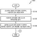
도 13은 일 실시예에 따라 전자 장치(1000)를 제어하는 방법을 설명하기 위한 흐름도이다.13 is a flowchart for explaining a method of controlling the
단계 S1310에서, 소스(200)에서 발생된 자기장에 기초하여, 사용자의 손의 좌표를 획득할 수 있다. 일 실시예에서, 전자 장치(1000)는 발생된 자기장의 세기를 감지하여, 사용자의 손의 좌표를 획득할 수 있다. 단계 S1320에서, 사용자의 움직임에 따른 소스(200)의 위치 변화를 감지할 수 있다. 일 실시예에서, 사용자의 움직임에 따라 소스(200)의 위치도 변하는 경우, 전자 장치(1000)는 적어도 하나의 센서를 이용하여 사용자의 움직임에 따른 소스(200)의 위치 변화를 알 수 있다. 단계 S1330에서, 감지된 소스(200)의 위치 변화에 기초하여 획득한 사용자의 손의 좌표를 가상 현실에 반영할 수 있다. 일 실시예에서, 전자 장치(1000)는 소스(200)의 위치 변화에 부합하게 사용자의 손의 좌표를 보정하여 가상 현실에 보정된 손의 좌표에 대응하는 임의의 형상의 UI를 전자 장치(1000)에서 제공하는 동영상 또는 이미지와 함께 디스플레이할 수 있다.In step S1310, based on the magnetic field generated in the
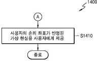
도 14는 일 실시예에 따라 전자 장치(1000)를 제어하는 방법에 있어 가상 현실을 제공하는 과정을 설명하기 위한 흐름도이다.FIG. 14 is a flowchart illustrating a process of providing a virtual reality in a method of controlling the
단계 S1410은 방법(1300)에 이어서, 도 13의 단계 S1330 이후에 사용자에게 사용자의 손의 좌표가 반영된 가상 현실을 제공할 수 있다. 일 실시예에서, 가상 현실 제공 장치(100)가 제공하는 가상 현실에는 사용자의 손의 좌표뿐만 아니라 사용자의 손 모양, 각 손가락의 구부러진 정도, 사용자의 손의 각도, 및 회전 정도 등도 반영될 수 있어, 실제 손과 동일하게 또는 부합하게 손 형상의 UI가 가상 현실에 반영될 수 있다.Step S1410 may follow the
일 실시예에서, 도 12b 내지 도 12d에 도시된 바와 같이, 모션 검출기(300)에 부착된 액세서리의 종류 또는 가상 현실 제공 장치(100)가 제공하는 컨텐츠의 종류 또는 미리 설정된 형태에 기초하여, 가상 현실 제공 장치(100)는 특화된 UI, GUI(graphical user interface)등을 제공할 수 있다. 예를 들어, 가상 현실 제공 장치(100)가 게임 컨텐츠를 제공하고, 모션 검출기(300)에 부착된 액세서리가 총 형상이면, 실제 사용자의 손의 위치와 각도에 부합하는 위치와 각도의 총 모양의 UI가 가상 현실에 반영될 수 있다. 또한, 예를 들어, 사용자가 총 형상의 액세서리의 방아쇠를 당기면, 가상 현실에 총 모양의 UI에서 총알이 발사될 수 있다. 사용자의 움직임에 부합하게 가상 현실에 반영되므로, 사용자는 더욱 가상현실에 몰입감을 느낄 수 있다.In one embodiment, based on the type of accessory attached to the
다양한 실시예들에서, 가상 현실을 제공한다는 의미는 가상 현실 제공 장치(100)가 사용자에게 가상 현실을 디스플레이하거나, 가상 현실 제공 장치(100)가 외부 디스플레이 장치(400)로 가상 현실을 전송하여, 외부 디스플레이 장치(400)가 디스플레이하는 것 또는 가상 현실 제공 장치(100)와 외부 디스플레이 장치(400)가 모두 가상 현실을 디스플레이하는 것일 수 있다.In various embodiments, providing a virtual reality means that the virtual
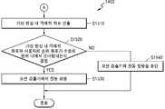
도 15는 일 실시예에 따라 모션 검출기(300)에서 진동이 발생하는 방법을 설명하기 위한 흐름도이다. 일 실시예에서, 도 15의 방법(1500)은 도 13의 방법(1300)에 이어진다.15 is a flowchart illustrating a method of generating vibration in the
단계 S1510에서, 사용자의 손의 좌표를 가상 현실에 반영한(S1330) 후에, 가상 현실 제공 장치(100)는 가상 현실 내 객체(object)의 좌표를 산출할 수 있다. 일 실시예에서, 가상 현실 내의 객체란, 가상 현실 제공 장치(100)가 제공하는 동영상 또는 이미지에 포함된 것으로서, 사람, 물건, 동물, 또는 건물 등을 포함할 수 있다. 예를 들어, 가상 현실 제공 장치(100)가 게임 컨텐츠를 제공할 경우, 가상 현실 내의 객체는 게임 컨텐츠 내의 몬스터(monster)가 될 수 있다.After the coordinates of the user's hand are reflected on the virtual reality in step S1510 (S1330), the virtual
단계 S1520에서, 가상 현실 제공 장치(100)는 산출한 가상 현실 내 객체의 좌표와 사용자의 손의 좌표가 소정의 범위 내에서 오버랩(overlap) 되는지를 결정할 수 있다. 일 실시예에서, 소정 범위는 가상 현실 제공 장치(100)가 제공하는 동영상 또는 이미지에서 특정 영역으로 정의되어 인식될 수 있는 것으로서, 하나 이상의 객체 또는 사용자의 손의 좌표를 포함할 수 있다. 예를 들어, 손의 좌표를 포함하는 특정 영역과 객체의 좌표를 포함하는 특정 영역이 오버랩되면, 가상 현실 제공 장치(100)는 사용자의 손의 좌표와 가상 현실 내 객체의 좌표가 소정의 범위 내에서 오버랩 된다고 결정할 수 있다.In step S1520, the virtual
단계 S1530에서, 가상 현실 제공 장치(100)가 오버랩 된다고 결정하면, 모션 검출기(300)에서 진동을 발생할 수 있다. 일 실시예에서, 가상 현실 제공 장치(100)가 상기 좌표들이 오버랩 된다고 결정하면, 진동 신호의 출력 이외에도 오디오 신호(예를 들어, 알림음), 비디오 신호등이 출력되거나, 가상 현실 상에서의 상호 작용과 함께 사용자에게 햅틱(haptic)과 같은 촉감을 느끼게 하거나, 또는 빛을 출력하는 등의 다양한 출력이 있을 수 있다. 예를 들어, 게임 컨텐츠에 있어, 가상 현실에 반영된 사용자의 손을 나타내는 UI가 몬스터를 잡으면, 모션 검출기(300)는 진동을 발생하여, 사용자는 가상 현실에서 수행한 동작에 대한 현실에서의 햅틱 피드백을 받을 수 있다.If it is determined in step S1530 that the virtual
단계 S1540에서, 가상 현실 제공 장치(100)가 오버랩 되지 않는다고 결정하면, 모션 검출기(300)에서 진동 발생을 중단할 수 있다. 일 실시예에서. 원래 진동이 발생하지 않은 상태라면, 아무 변화도 일어나지 않을 수 있다. If it is determined in step S1540 that the virtual
도 16은 일 실시예에 따라 모션 검출기(300)에서 생성하는 모션 데이터의 필드를 설명하기 위한 도면이다.16 is a diagram for explaining fields of motion data generated by the
도 15에 도시된 바와 같이, 일 실시예 따른 모션 검출기(300)는 유도된 전류의 세기를 인식하여, 사용자의 움직임을 감지하며, 감지된 사용자의 움직임에 대한 모션 데이터를 생성할 수 있다. 일 실시예에서, 사용자의 움직임에 대한 모션 데이터는 Data Start, 장치 종류, 장치 상태, 메시지 종류, 손 위치 정보, 손 회전 정보, 손가락 움직임 정보, 버튼 정보, Data End 중 선택된 하나 이상의 필드를 포함할 수 있다.As shown in FIG. 15, the
일 실시예에서, 모션 검출기(300)는 사용자의 움직임에 대한 모션 데이터를 가상 현실 제공 장치(100)로 전송할 수 있고, 가상 현실 제공 장치(100)는 수신한 모션 데이터를 사용자의 움직임에 부합하게 보정하여, 가상 현실 내 객체의 동작 제어가 이루어지도록 할 수 있다.In one embodiment, the
도 17은 일 실시예에 따라 모션 검출기(300)에서 생성하는 모션 데이터의 필드에 대하여 구체적으로 설명하기 위한 도면이다. 도 15로 돌아가서, 모션 검출기(300)는 Data Start, 장치 종류, 장치 상태, 메시지 종류, 손 위치 정보, 손 회전 정보, 손가락 움직임 정보, 버튼 정보, Data End 중 선택된 하나 이상을 포함하는 사용자의 움직임에 대한 모션 데이터의 필드를 생성하는데, 도 16을 참조하여, 모션 검출기(300)가 생성하는 모션 데이터의 필드에 대한 설명을 상세히 살펴보겠다.FIG. 17 is a diagram for specifically explaining fields of motion data generated by the
일 실시예에서, "Data Start"는 메시지의 시작을 알리고, 메시지의 무결성 확인에 사용될 수 있다.In one embodiment, "Data Start" informs the start of the message and can be used to verify the integrity of the message.
일 실시예에서, "장치 종류"는 모션 검출기(300)가 왼손용인지 오른손용인지 등에 대한 정보를 표시할 수 있다. 예를 들어, 왼손용이면 1로, 오른손용이면 2로 표시할 수 있다. 또한, 일 실시예에서, "장치 종류"는 모션 검출기(300)에 액세서리가 부착된 상태 정보를 표시할 수 있다. 예를 들어, 왼손용에 조이스틱 액세서리가 부착된 상태면 1-1로, 왼손용에 총 액세서리가 부착된 상태면 1-2로, 오른손용에 조이스틱 액세서리가 부착된 상태면 2-1로, 오른손용에 총 액세서리가 부착된 상태면 2-2로 표시할 수 있다.In one embodiment, the "device type" can display information about whether the
일 실시예에서, "장치 상태"는 모션 검출기(300)의 현재 상태를 표시할 수 있다. 예를 들어, Disconnected는 연결이 해지된 상태, Calibrating은 초기 설정 값 조정 상태, Disabled는 연결은 되어있지만, 사용자에 의해 동작은 멈춘 상태, Connected는 정상적인 데이터를 송수신하는 상태를 의미할 수 있다.In one embodiment, the "device state" may indicate the current state of the
일 실시예에서, "메시지 종류"는 현재 메시지의 종류를 의미할 수 있다. 예를 들어, Information은 장치의 정보에 대한 것이고, Action은 장치의 움직임 정보에 대한 것일 수 있다.In one embodiment, "message type" may refer to the type of the current message. For example, Information is about the device's information, and Action may be about the motion information of the device.
일 실시예에서, "손 위치 정보"는 가상 현실 제공 장치(100)의 소스(200) 대비 상대 위치를 x, y, z 좌표계 상의 값으로 표시한 정보이고, "손 회전 정보"는 가상 현실 제공 장치(100)의 소스(200) 대비 회전 값을 x축, y축, z축 회전 값으로 표시한 정보일 수 있다. 예를 들어, 손 위치 정보는 (0.44, 0.31, 1.2)를 나타낸 정보이고 손 회전 정보는
일 실시예에서, "손가락 움직임 정보"는 손가락의 움직임에 대한 정보를 표현한 값일 수 있다. 예를 들어, 각 손가락 별 기울어짐 값을 0에서 1사이의 실수 값으로 표현할 수 있다. 예를 들어, 0은 손가락을 완전히 편 상태이고, 1은 손가락을 최대한 구부린 상태일 수 있다.In one embodiment, the "finger motion information" may be a value representing information about movement of the finger. For example, the tilt value of each finger can be expressed as a real value between 0 and 1. For example, 0 may be a state in which the finger is completely flipped, and 1 may be a state in which the finger is bent to the maximum.
일 실시예에서, "버튼 정보"는 물리적인 버튼이 눌려진 상태를 표현한다. 예를 들어, 0은 버튼이 눌리지 않은 상태이고, 0.5는 버튼의 반누름(half press) 상태이고, 1은 버튼이 완전히 눌려진(full press) 상태일 수 있다. 일 실시예에서, "Data End"는 데이터의 끝을 알리고, 데이터의 무결성 확인용으로 사용될 수 있다.In one embodiment, "button information" represents a pressed state of a physical button. For example, 0 may be a state in which the button is not pressed, 0.5 is a half-press state of the button, and 1 may be a state where the button is fully pressed. In one embodiment, "Data End" informs the end of the data and can be used for integrity verification of the data.
본 개시에 의해 사용자의 손의 움직임을 가상 현실에 보다 정확하게 반영할 수 있고, 햅틱을 통해서 컨텐츠와 상호작용이 가능하다. 이로 인해 사용자에게 가상 현실에의 실제적인 몰입감을 제공할 수 있다. 또한, 사용자에게 단순한 감상형 컨텐츠가 아닌, 참여형 컨텐츠를 제공하는 장점이 있다.By this disclosure, the motion of the user's hand can be more accurately reflected in the virtual reality, and it is possible to interact with the content through the haptic. This can provide the user with a real immersion feeling in the virtual reality. In addition, there is an advantage in that the user is provided not with simple sentimental content but with participatory content.
한편, 상술한 본 발명의 실시예에 따른 가상 현실 인터페이스를 제어하는 방법은 컴퓨터에서 실행될 수 있는 프로그램으로 작성가능하고, 컴퓨터로 읽을 수 있는 기록매체를 이용하여 이와 같은 프로그램을 동작시키는 범용 디지털 컴퓨터에서 구현될 수 있다. 이와 같은 컴퓨터로 읽을 수 있는 기록매체는 마그네틱 저장매체(예를 들면, 롬, 플로피 디스크, 하드 디스크 등), 광학적 판독 매체(예를 들면, 시디롬, 디브이디 등)와 같은 저장매체를 포함한다. 또한, 컴퓨터가 읽을 수 있는 복수의 기록 매체가 네트워크로 연결된 컴퓨터 시스템들에 분산되어 있을 수 있으며, 분산된 기록 매체들에 저장된 데이터(예를 들어, 프로그램 명령어 및 코드)가 적어도 하나의 컴퓨터에 의해 실행될 수 있다.Meanwhile, a method for controlling a virtual reality interface according to an embodiment of the present invention can be realized by a general-purpose digital computer that can be created as a program that can be executed by a computer and operates the program using a computer-readable recording medium Can be implemented. Such a computer readable recording medium includes a storage medium such as a magnetic storage medium (e.g., ROM, floppy disk, hard disk, etc.), optical reading medium (e.g., CD ROM, DVD, etc.). In addition, a plurality of computer-readable recording media may be distributed over networked computer systems, and data (e.g., program instructions and code) stored on distributed recording media may be stored on at least one computer Lt; / RTI >
이제까지 실시예들을 중심으로 살펴보았다. 개시된 실시예들이 속하는 기술 분야에서 통상의 지식을 가진 자는 개시된 실시예들이 본질적인 특성에서 벗어나지 않는 범위에서 변형된 형태로 구현될 수 있음을 이해할 수 있을 것이다. 그러므로 개시된 실시예들은 한정적인 관점이 아니라 설명적인 관점에서 고려되어야 한다. 실시예들에 따른 발명의 범위는 전술한 설명이 아니라 특허청구범위에 나타나 있으며, 그와 동등한 범위 내에 있는 모든 차이점은 발명의 범위에 포함된 것으로 해석되어야 할 것이다.So far, the embodiments have been mainly described. It will be understood by those skilled in the art that the disclosed embodiments may be embodied in various other forms without departing from the essential characteristics thereof. Therefore, the disclosed embodiments should be considered in an illustrative rather than a restrictive sense. The scope of the invention in accordance with the embodiments is set forth in the appended claims rather than the foregoing description, and all differences within the scope of equivalents thereof should be construed as being included in the scope of the invention.
본 명세서에 기재된 "...부", "모듈" 등의 용어는 적어도 하나의 기능이나 동작을 처리하는 단위를 의미하며, 이는 하드웨어 또는 소프트웨어로 구현되거나 하드웨어와 소프트웨어의 결합으로 구현될 수 있다.The terms " part, "" module, " and the like, as used herein, refer to a unit that processes at least one function or operation, and may be implemented in hardware or software or a combination of hardware and software.
"부", "모듈"은 어드레싱될 수 있는 저장 매체에 저장되며 프로세서에 의해 실행될 수 있는 프로그램에 의해 구현될 수도 있다."Module" may be embodied by a program stored on a storage medium that can be addressed and that may be executed by a processor.
예를 들어, "부", "모듈" 은 소프트웨어 구성 요소들, 객체 지향 소프트웨어 구성 요소들, 클래스 구성 요소들 및 태스크 구성 요소들과 같은 구성 요소들과, 프로세스들, 함수들, 속성들, 프로시저들, 서브루틴들, 프로그램 코드의 세그먼트들, 드라이버들, 펌웨어, 마이크로 코드, 회로, 데이터, 데이터베이스, 데이터 구조들, 테이블들, 어레이들 및 변수들에 의해 구현될 수 있다.For example, "part" or "module" may include components such as software components, object oriented software components, class components and task components, Microcode, circuitry, data, databases, data structures, tables, arrays, and variables, as will be appreciated by those skilled in the art.
Claims (24)
Translated fromKorean상기 발생된 자기장에 기초하여, 사용자의 손의 좌표를 획득하는 모션 검출기(motion detector); 및
상기 모션 검출기로부터 수신한 상기 사용자의 손의 좌표를 상기 사용자의 움직임에 따른 상기 소스의 위치 변화에 기초하여 가상 현실에 반영하는 가상 현실 제공 장치;
를 포함하는 전자 장치.
A source generating a magnetic field;
A motion detector for obtaining coordinates of a user's hand based on the generated magnetic field; And
A virtual reality providing device for reflecting the coordinates of the hand of the user received from the motion detector to the virtual reality based on a change in the position of the source according to the movement of the user;
≪ / RTI >
상기 가상 현실 제공 장치는 상기 소스를 탈부착 가능한, 전자 장치.
The method according to claim 1,
Wherein the virtual reality providing device is detachable from the source.
상기 가상 현실 제공 장치는 상기 모션 검출기에서 수신한 상기 소스의 위치를 기준으로 한 사용자의 손의 좌표를, 상기 사용자의 움직임에 따른 상기 소스의 위치 변화에 기초하여, 상기 사용자의 몸의 일부를 기준으로 보정하는, 전자 장치.
The method according to claim 1,
Wherein the virtual reality providing apparatus is configured to set coordinates of a hand of a user based on a position of the source received by the motion detector as a reference of a part of the user's body based on a change in position of the source in accordance with movement of the user . ≪ / RTI >
상기 가상 현실 제공 장치는 상기 모션 검출기에서 수신한 상기 소스의 위치를 기준으로 한 사용자의 손의 좌표를, 상기 사용자의 머리 움직임에 따른 상기 소스의 위치 변화에 기초하여, 상기 사용자의 흉부를 기준으로 보정하는, 전자 장치.
The method according to claim 1,
Wherein the virtual reality providing apparatus is configured to set coordinates of the hand of the user based on the position of the source received by the motion detector on the basis of the change of the position of the source in accordance with the head movement of the user, / RTI >
상기 가상 현실 제공 장치는,
상기 모션 검출기와 통신하는 통신 인터페이스;
상기 사용자의 움직임을 감지하는 센서;
상기 모션 검출기로부터 수신한 사용자의 손의 좌표를 상기 사용자의 몸의 일부를 기준으로 보정하여 상기 사용자의 손의 좌표를 구하는 프로세서;
를 포함하는, 전자 장치.
The method according to claim 1,
The virtual reality providing apparatus includes:
A communication interface for communicating with the motion detector;
A sensor for sensing movement of the user;
A processor for correcting coordinates of a user's hand received from the motion detector based on a part of the user's body to obtain coordinates of the user's hand;
.
상기 가상 현실 제공 장치는,
상기 사용자의 손의 좌표를 반영한 상기 가상 현실을 상기 사용자에게 디스플레이하는 디스플레이를 더 포함하는 전자 장치.
6. The method of claim 5,
The virtual reality providing apparatus includes:
Further comprising a display for displaying to the user the virtual reality that reflects the coordinates of the user's hand.
상기 통신 인터페이스는,
외부의 디스플레이 장치로 상기 사용자의 손의 좌표를 반영한 상기 가상 현실을 전송하는, 전자 장치.
6. The method of claim 5,
Wherein the communication interface comprises:
And transmits the virtual reality reflecting the coordinates of the user's hand to an external display device.
상기 가상 현실 제공 장치는,
상기 모션 검출기로부터 수신한 모션 검출기의 종류 정보에 기초하여, 변경된 가상 현실을 제공하는, 전자 장치.
The method according to claim 1,
The virtual reality providing apparatus includes:
And provides the changed virtual reality based on the type information of the motion detector received from the motion detector.
상기 가상 현실 제공 장치는,
상기 가상 현실 내 객체 좌표와 상기 사용자의 손의 좌표에 기초하여 진동 발생 신호를 생성하는, 전자 장치.
The method according to claim 1,
The virtual reality providing apparatus includes:
And generates a vibration generation signal based on the object coordinates in the virtual reality and the coordinates of the user's hand.
상기 사용자의 움직임을 반영한 가상 현실을 생성하는 가상 현실 제공 장치에 상기 획득된 모션 데이터를 전송하는 통신 인터페이스;
를 포함하는, 모션 검출기.
A control unit for obtaining motion data including at least one of motion information of a user's hand, kind of a motion detector, kind of an accessory coupled to the motion detector, operation state of the motion detector, and button push information of the motion detector; And
A communication interface for transmitting the obtained motion data to a virtual reality providing device for generating a virtual reality reflecting movement of the user;
And a motion detector.
을 더 포함하는, 모션 검출기.
11. The apparatus of claim 10, further comprising: a housing detachable into a first portion including the control portion and the communication interface and a second portion different from the first portion;
Further comprising a motion detector.
상기 하우징은,
상기 하우징의 어느 일부가 구부러진 형태를 포함하고, 상기 사용자의 손의 어느 일부에 상기 구부러진 형태의 일부가 거치되는, 모션 검출기.
12. The method of claim 11,
The housing includes:
Wherein a portion of the housing includes a bent shape and a portion of the bent shape is mounted to a portion of the user's hand.
상기 하우징은,
상기 사용자의 손가락의 움직임을 감지하는 적어도 하나의 센서를 상기 하우징의 적어도 하나의 측면에 위치시키는, 모션 검출기.
12. The method of claim 11,
The housing includes:
And position at least one sensor on at least one side of the housing for sensing movement of the user's finger.
상기 제 2 부분을 대신하여 상기 제 1 부분에 조작 가능한 액세서리를 결합할 수 있는, 모션 검출기.
12. The apparatus of claim 11,
And to couple an operable accessory to the first portion in place of the second portion.
사용자 입력을 수신하는 입력부;
상기 센싱된 자기장에 기초한 제 1 데이터 및 상기 수신된 사용자 입력에 기초한 제 2 데이터를 포함하는 모션 데이터를 생성하는 제어부; 및
가상 현실을 생성하는 가상 현실 제공 장치로 상기 모션 데이터를 전송하는 통신 인터페이스;
를 포함하는, 모션 검출기.
A sensor unit for sensing a magnetic field;
An input for receiving user input;
A control unit for generating motion data including first data based on the sensed magnetic field and second data based on the received user input; And
A communication interface for transmitting the motion data to a virtual reality providing device for generating a virtual reality;
And a motion detector.
상기 사용자의 움직임에 따른 상기 소스의 위치 변화를 감지하는 단계; 및
상기 획득된 사용자의 손의 좌표를 상기 감지된 소스의 위치 변화에 기초하여 가상 현실에 반영하는 단계;
를 포함하는 전자 장치를 제어하는 방법.
Obtaining coordinates of the user's hand based on the magnetic field generated at the source;
Detecting a change in the position of the source according to a movement of the user; And
Reflecting coordinates of the obtained hand of the user to a virtual reality based on a change in the position of the detected source;
Wherein the electronic device is an electronic device.
가상 현실 제공 장치에 자기장을 발생하는 상기 소스를 부착하는 단계를 더 포함하고,
상기 획득하는 단계는,
상기 부착된 소스에서 발생된 자기장에 기초하여, 상기 사용자의 손의 좌표를 획득하는, 전자 장치를 제어하는 방법.
17. The method of claim 16,
Further comprising the step of attaching said source generating a magnetic field to a virtual reality providing device,
Wherein the acquiring comprises:
And acquiring coordinates of the user's hand based on a magnetic field generated at the attached source.
상기 사용자의 움직임에 따른 상기 감지된 소스의 위치 변화에 기초하여, 상기 소스의 위치를 기준으로 한 상기 사용자의 손의 좌표를 상기 사용자의 몸의 일부를 기준으로 보정하는 단계를 포함하는 전자 장치를 제어하는 방법.
17. The method of claim 16, wherein the step of reflecting the coordinates of the obtained hand of the user to the virtual reality comprises:
And correcting the coordinates of the user's hand based on the position of the source based on a change in the position of the detected source in accordance with the movement of the user, How to control.
19. The method of claim 18, wherein the movement of the user is head movement of the user, and a portion of the body of the user is the chest of the user.
상기 사용자의 손의 좌표를 반영한 상기 가상 현실을 상기 사용자에게 디스플레이하는 단계를 더 포함하는 전자 장치를 제어하는 방법.
17. The method of claim 16,
And displaying the virtual reality to the user reflecting the coordinates of the user's hand.
외부의 디스플레이 장치로 상기 사용자의 손의 좌표를 반영한 상기 가상 현실을 전송하는 단계를 더 포함하는 전자 장치를 제어하는 방법.
17. The method of claim 16,
And transmitting the virtual reality reflecting the coordinates of the user's hand to an external display device.
상기 가상 현실 내 객체 좌표와 상기 사용자의 반영된 손의 좌표에 기초하여 진동 발생 신호를 생성하는 단계를 더 포함하는 전자 장치를 제어하는 방법.
17. The method of claim 16,
Generating a vibration generating signal based on the coordinates of the object in the virtual reality and the coordinates of the user's reflected hand.
상기 진동을 발생 신호를 생성하는 단계는,
상기 가상 현실 내 객체 좌표를 산출하는 단계;
상기 객체 좌표와 상기 반영된 사용자의 손의 좌표가 소정의 범위 내에서 오버랩되는지 결정하는 단계; 및
상기 결정에 기초하여 진동을 생성하는 단계;
를 포함하는 전자 장치를 제어하는 방법.
23. The method of claim 22,
The step of generating the vibration generating signal includes:
Calculating object coordinates in the virtual reality;
Determining whether the object coordinates and the coordinates of the reflected user's hand overlap within a predetermined range; And
Generating vibration based on the determination;
Wherein the electronic device is an electronic device.
상기 사용자의 손의 좌표를 획득하는 단계는,
상기 사용자의 손의 좌표를 획득하는 모션 검출기의 일 측면에 위치하는 적어도 하나의 센서를 이용하여 상기 사용자의 손가락 움직임 정보를 더 획득하는 단계를 포함하는 전자 장치를 제어하는 방법.17. The method of claim 16,
The step of acquiring the coordinates of the user's hand comprises:
And acquiring further finger motion information of the user using at least one sensor located on one side of the motion detector that obtains the coordinates of the user's hand.
Priority Applications (1)
| Application Number | Priority Date | Filing Date | Title |
|---|---|---|---|
| US15/390,229US10338688B2 (en) | 2015-12-24 | 2016-12-23 | Electronic device and method of controlling the same |
Applications Claiming Priority (4)
| Application Number | Priority Date | Filing Date | Title |
|---|---|---|---|
| US201562387184P | 2015-12-24 | 2015-12-24 | |
| US62/387,184 | 2015-12-24 | ||
| KR1020160055768AKR20170076534A (en) | 2015-12-24 | 2016-05-04 | Virtual reality interface apparatus and method for controlling the apparatus |
| KR1020160055768 | 2016-05-04 |
Publications (2)
| Publication Number | Publication Date |
|---|---|
| KR20170076544Atrue KR20170076544A (en) | 2017-07-04 |
| KR102677050B1 KR102677050B1 (en) | 2024-06-24 |
Family
ID=59356923
Family Applications (2)
| Application Number | Title | Priority Date | Filing Date |
|---|---|---|---|
| KR1020160055768APendingKR20170076534A (en) | 2015-12-24 | 2016-05-04 | Virtual reality interface apparatus and method for controlling the apparatus |
| KR1020160147636AActiveKR102677050B1 (en) | 2015-12-24 | 2016-11-07 | Electronic device and method for controlling the electronic device |
Family Applications Before (1)
| Application Number | Title | Priority Date | Filing Date |
|---|---|---|---|
| KR1020160055768APendingKR20170076534A (en) | 2015-12-24 | 2016-05-04 | Virtual reality interface apparatus and method for controlling the apparatus |
Country Status (1)
| Country | Link |
|---|---|
| KR (2) | KR20170076534A (en) |
Cited By (5)
| Publication number | Priority date | Publication date | Assignee | Title |
|---|---|---|---|---|
| WO2019083113A1 (en)* | 2017-10-23 | 2019-05-02 | 주식회사 디미콜론 | Controller and simulation system including same |
| KR20190108336A (en)* | 2018-03-14 | 2019-09-24 | 고려대학교 산학협력단 | Finger-wearable wireless controller apparatus and wireless control method using the same |
| KR20200081915A (en)* | 2018-12-28 | 2020-07-08 | 중앙대학교 산학협력단 | Virtual Reality Karaoke Interaction Method and Apparatus |
| KR20200082931A (en)* | 2018-12-31 | 2020-07-08 | (주)엠라인스튜디오 | Wearable device for virtual reality |
| KR20200091255A (en)* | 2019-01-22 | 2020-07-30 | (주)스코넥엔터테인먼트 | Virtual Reality Control System |
Families Citing this family (3)
| Publication number | Priority date | Publication date | Assignee | Title |
|---|---|---|---|---|
| KR102654621B1 (en) | 2016-12-08 | 2024-04-04 | 삼성전자주식회사 | Method for displaying object and electronic device thereof |
| KR102181499B1 (en)* | 2019-03-14 | 2020-11-23 | 주식회사 듀코젠 | Method and system for authoring virtual reality contents with two hands motion input |
| KR102475743B1 (en)* | 2020-08-03 | 2022-12-08 | 주식회사 탑앤피 | Taekwondo training system using AR and VR equipment |
Citations (7)
| Publication number | Priority date | Publication date | Assignee | Title |
|---|---|---|---|---|
| US5670987A (en)* | 1993-09-21 | 1997-09-23 | Kabushiki Kaisha Toshiba | Virtual manipulating apparatus and method |
| US20030062675A1 (en)* | 2001-09-28 | 2003-04-03 | Canon Kabushiki Kaisha | Image experiencing system and information processing method |
| US20060007137A1 (en)* | 2003-05-14 | 2006-01-12 | Infocus Corporation | User-interface for a projection device |
| US20110187638A1 (en)* | 2010-02-01 | 2011-08-04 | Tzu-Yi Chao | Interactive module applied in 3D interactive system and method |
| US20110199305A1 (en)* | 2008-11-07 | 2011-08-18 | Changsu Suh | Mouse controlled by movements of fingers in the air |
| US20140240225A1 (en)* | 2013-02-26 | 2014-08-28 | Pointgrab Ltd. | Method for touchless control of a device |
| US9360682B1 (en)* | 2014-05-07 | 2016-06-07 | Remote Xccess, LLC | Camera headband device and system with attachable apparatus |
- 2016
- 2016-05-04KRKR1020160055768Apatent/KR20170076534A/enactivePending
- 2016-11-07KRKR1020160147636Apatent/KR102677050B1/enactiveActive
Patent Citations (7)
| Publication number | Priority date | Publication date | Assignee | Title |
|---|---|---|---|---|
| US5670987A (en)* | 1993-09-21 | 1997-09-23 | Kabushiki Kaisha Toshiba | Virtual manipulating apparatus and method |
| US20030062675A1 (en)* | 2001-09-28 | 2003-04-03 | Canon Kabushiki Kaisha | Image experiencing system and information processing method |
| US20060007137A1 (en)* | 2003-05-14 | 2006-01-12 | Infocus Corporation | User-interface for a projection device |
| US20110199305A1 (en)* | 2008-11-07 | 2011-08-18 | Changsu Suh | Mouse controlled by movements of fingers in the air |
| US20110187638A1 (en)* | 2010-02-01 | 2011-08-04 | Tzu-Yi Chao | Interactive module applied in 3D interactive system and method |
| US20140240225A1 (en)* | 2013-02-26 | 2014-08-28 | Pointgrab Ltd. | Method for touchless control of a device |
| US9360682B1 (en)* | 2014-05-07 | 2016-06-07 | Remote Xccess, LLC | Camera headband device and system with attachable apparatus |
Non-Patent Citations (1)
| Title |
|---|
| 최인규 외 1명. 가상 현실에서 모션캡쳐의 활용가능성에 관한 연구. 2002년 한국멀티미디어학회 추계학술발표논문집 491-496 페이지. 2002년11월. 1부.** |
Cited By (5)
| Publication number | Priority date | Publication date | Assignee | Title |
|---|---|---|---|---|
| WO2019083113A1 (en)* | 2017-10-23 | 2019-05-02 | 주식회사 디미콜론 | Controller and simulation system including same |
| KR20190108336A (en)* | 2018-03-14 | 2019-09-24 | 고려대학교 산학협력단 | Finger-wearable wireless controller apparatus and wireless control method using the same |
| KR20200081915A (en)* | 2018-12-28 | 2020-07-08 | 중앙대학교 산학협력단 | Virtual Reality Karaoke Interaction Method and Apparatus |
| KR20200082931A (en)* | 2018-12-31 | 2020-07-08 | (주)엠라인스튜디오 | Wearable device for virtual reality |
| KR20200091255A (en)* | 2019-01-22 | 2020-07-30 | (주)스코넥엔터테인먼트 | Virtual Reality Control System |
Also Published As
| Publication number | Publication date |
|---|---|
| KR102677050B1 (en) | 2024-06-24 |
| KR20170076534A (en) | 2017-07-04 |
Similar Documents
| Publication | Publication Date | Title |
|---|---|---|
| US10338688B2 (en) | Electronic device and method of controlling the same | |
| KR102677050B1 (en) | Electronic device and method for controlling the electronic device | |
| KR101541082B1 (en) | System and method for rehabilitation exercise of the hands | |
| JP7642748B2 (en) | Position indicating device and computer | |
| CN105759422B (en) | Display system and control method of display device | |
| US20180253152A1 (en) | Gesture-controlled augmented reality experience using a mobile communications device | |
| KR102643112B1 (en) | Electronic device and method for controlling the same | |
| JP2023053397A (en) | Coordinate calculation system | |
| US20120262487A1 (en) | Interactive multi-display control systems | |
| JP6396070B2 (en) | Image fusion system, information processing apparatus, information terminal, and information processing method | |
| CN107106032A (en) | The apparatus and method for controlling wearable device | |
| JP2001356875A (en) | Pointer display system | |
| JP2018072992A (en) | Information processing method and equipment and program making computer execute the information processing method | |
| JP2017134558A (en) | Information processor, information processing method, and computer-readable recording medium recorded with program | |
| JP2018041341A (en) | Information processing method and program for causing computer to execute information processing method | |
| JP6740584B2 (en) | Display system, display device control method, and program | |
| JP6996115B2 (en) | Head-mounted display device, program, and control method of head-mounted display device | |
| JP6439448B2 (en) | Display system, program, and control method for display device | |
| KR20200066962A (en) | Electronic device and method for providing content based on the motion of the user | |
| JP2018022426A (en) | Display device, head-mounted display device, and method for controlling display device | |
| JP6932917B2 (en) | Head-mounted display, program, and head-mounted display control method | |
| JP6373537B1 (en) | Spatial position indication system | |
| WO2016157938A1 (en) | Information processing device, information processing method, and program | |
| JP2019192250A (en) | Information processing method, apparatus, and program causing computer to execute the method | |
| KR101605474B1 (en) | 3d pointing device based on finger gesture and presentation system using the same |
Legal Events
| Date | Code | Title | Description |
|---|---|---|---|
| PA0109 | Patent application | Patent event code:PA01091R01D Comment text:Patent Application Patent event date:20161107 | |
| PG1501 | Laying open of application | ||
| A201 | Request for examination | ||
| PA0201 | Request for examination | Patent event code:PA02012R01D Patent event date:20211102 Comment text:Request for Examination of Application Patent event code:PA02011R01I Patent event date:20161107 Comment text:Patent Application | |
| E902 | Notification of reason for refusal | ||
| PE0902 | Notice of grounds for rejection | Comment text:Notification of reason for refusal Patent event date:20230531 Patent event code:PE09021S01D | |
| E90F | Notification of reason for final refusal | ||
| PE0902 | Notice of grounds for rejection | Comment text:Final Notice of Reason for Refusal Patent event date:20231228 Patent event code:PE09021S02D | |
| E701 | Decision to grant or registration of patent right | ||
| PE0701 | Decision of registration | Patent event code:PE07011S01D Comment text:Decision to Grant Registration Patent event date:20240315 | |
| GRNT | Written decision to grant | ||
| PR0701 | Registration of establishment | Comment text:Registration of Establishment Patent event date:20240617 Patent event code:PR07011E01D | |
| PR1002 | Payment of registration fee | Payment date:20240618 End annual number:3 Start annual number:1 | |
| PG1601 | Publication of registration |