KR20170074842A - System and method for integrated surgical table motion - Google Patents
System and method for integrated surgical table motionDownload PDFInfo
- Publication number
- KR20170074842A KR20170074842AKR1020177004045AKR20177004045AKR20170074842AKR 20170074842 AKR20170074842 AKR 20170074842AKR 1020177004045 AKR1020177004045 AKR 1020177004045AKR 20177004045 AKR20177004045 AKR 20177004045AKR 20170074842 AKR20170074842 AKR 20170074842A
- Authority
- KR
- South Korea
- Prior art keywords
- coordinate frame
- surgical table
- motion
- movement
- joints
- Prior art date
- Legal status (The legal status is an assumption and is not a legal conclusion. Google has not performed a legal analysis and makes no representation as to the accuracy of the status listed.)
- Granted
Links
- 230000033001locomotionEffects0.000titleclaimsabstractdescription351
- 238000000034methodMethods0.000titleclaimsdescription110
- 239000012636effectorSubstances0.000claimsabstractdescription118
- 238000003384imaging methodMethods0.000claimsabstractdescription78
- 230000001131transforming effectEffects0.000claimsdescription9
- 210000001503jointAnatomy0.000description87
- 230000000875corresponding effectEffects0.000description68
- 230000009466transformationEffects0.000description54
- 230000008569processEffects0.000description52
- 230000008859changeEffects0.000description16
- 206010028980NeoplasmDiseases0.000description13
- 238000010586diagramMethods0.000description13
- 201000011510cancerDiseases0.000description10
- 239000011295pitchSubstances0.000description10
- 238000001356surgical procedureMethods0.000description10
- 238000012986modificationMethods0.000description8
- 230000004048modificationEffects0.000description8
- 230000000712assemblyEffects0.000description6
- 238000000429assemblyMethods0.000description6
- 238000003780insertionMethods0.000description6
- 230000037431insertionEffects0.000description6
- 210000000323shoulder jointAnatomy0.000description6
- 238000000844transformationMethods0.000description6
- 230000005484gravityEffects0.000description5
- 239000011159matrix materialSubstances0.000description5
- 230000008602contractionEffects0.000description4
- 238000006243chemical reactionMethods0.000description3
- 230000001276controlling effectEffects0.000description3
- 230000006870functionEffects0.000description3
- 210000000056organAnatomy0.000description3
- 230000002441reversible effectEffects0.000description3
- RYGMFSIKBFXOCR-UHFFFAOYSA-NCopperChemical compound[Cu]RYGMFSIKBFXOCR-UHFFFAOYSA-N0.000description2
- 210000003484anatomyAnatomy0.000description2
- 238000003491arrayMethods0.000description2
- 238000004891communicationMethods0.000description2
- 229910052802copperInorganic materials0.000description2
- 239000010949copperSubstances0.000description2
- 230000006378damageEffects0.000description2
- 238000013461designMethods0.000description2
- 230000000694effectsEffects0.000description2
- 230000003068static effectEffects0.000description2
- 238000012800visualizationMethods0.000description2
- 208000027418Wounds and injuryDiseases0.000description1
- 239000008186active pharmaceutical agentSubstances0.000description1
- 230000002917arthritic effectEffects0.000description1
- 239000003795chemical substances by applicationSubstances0.000description1
- 230000002301combined effectEffects0.000description1
- 230000001447compensatory effectEffects0.000description1
- 239000002131composite materialSubstances0.000description1
- 238000012937correctionMethods0.000description1
- 230000002596correlated effectEffects0.000description1
- 230000006735deficitEffects0.000description1
- 239000011521glassSubstances0.000description1
- 208000014674injuryDiseases0.000description1
- 230000002452interceptive effectEffects0.000description1
- 238000001990intravenous administrationMethods0.000description1
- 238000002357laparoscopic surgeryMethods0.000description1
- 230000007774longtermEffects0.000description1
- 238000013507mappingMethods0.000description1
- 230000013011matingEffects0.000description1
- QSHDDOUJBYECFT-UHFFFAOYSA-NmercuryChemical compound[Hg]QSHDDOUJBYECFT-UHFFFAOYSA-N0.000description1
- 229910052753mercuryInorganic materials0.000description1
- 230000003287optical effectEffects0.000description1
- 230000036544postureEffects0.000description1
- 238000012545processingMethods0.000description1
- 230000000644propagated effectEffects0.000description1
- 230000001954sterilising effectEffects0.000description1
- 238000004659sterilization and disinfectionMethods0.000description1
- 230000002459sustained effectEffects0.000description1
- 238000013519translationMethods0.000description1
- MBYLVOKEDDQJDY-UHFFFAOYSA-Ntris(2-aminoethyl)amineChemical compoundNCCN(CCN)CCNMBYLVOKEDDQJDY-UHFFFAOYSA-N0.000description1
Images


Classifications
- A—HUMAN NECESSITIES
- A61—MEDICAL OR VETERINARY SCIENCE; HYGIENE
- A61B—DIAGNOSIS; SURGERY; IDENTIFICATION
- A61B34/00—Computer-aided surgery; Manipulators or robots specially adapted for use in surgery
- A61B34/30—Surgical robots
- A—HUMAN NECESSITIES
- A61—MEDICAL OR VETERINARY SCIENCE; HYGIENE
- A61B—DIAGNOSIS; SURGERY; IDENTIFICATION
- A61B34/00—Computer-aided surgery; Manipulators or robots specially adapted for use in surgery
- A61B34/20—Surgical navigation systems; Devices for tracking or guiding surgical instruments, e.g. for frameless stereotaxis
- A—HUMAN NECESSITIES
- A61—MEDICAL OR VETERINARY SCIENCE; HYGIENE
- A61B—DIAGNOSIS; SURGERY; IDENTIFICATION
- A61B34/00—Computer-aided surgery; Manipulators or robots specially adapted for use in surgery
- A61B34/70—Manipulators specially adapted for use in surgery
- A—HUMAN NECESSITIES
- A61—MEDICAL OR VETERINARY SCIENCE; HYGIENE
- A61B—DIAGNOSIS; SURGERY; IDENTIFICATION
- A61B90/00—Instruments, implements or accessories specially adapted for surgery or diagnosis and not covered by any of the groups A61B1/00 - A61B50/00, e.g. for luxation treatment or for protecting wound edges
- A61B90/36—Image-producing devices or illumination devices not otherwise provided for
- A61B90/37—Surgical systems with images on a monitor during operation
- A—HUMAN NECESSITIES
- A61—MEDICAL OR VETERINARY SCIENCE; HYGIENE
- A61G—TRANSPORT, PERSONAL CONVEYANCES, OR ACCOMMODATION SPECIALLY ADAPTED FOR PATIENTS OR DISABLED PERSONS; OPERATING TABLES OR CHAIRS; CHAIRS FOR DENTISTRY; FUNERAL DEVICES
- A61G13/00—Operating tables; Auxiliary appliances therefor
- A61G13/02—Adjustable operating tables; Controls therefor
- A—HUMAN NECESSITIES
- A61—MEDICAL OR VETERINARY SCIENCE; HYGIENE
- A61B—DIAGNOSIS; SURGERY; IDENTIFICATION
- A61B90/00—Instruments, implements or accessories specially adapted for surgery or diagnosis and not covered by any of the groups A61B1/00 - A61B50/00, e.g. for luxation treatment or for protecting wound edges
- A61B90/36—Image-producing devices or illumination devices not otherwise provided for
- A61B90/37—Surgical systems with images on a monitor during operation
- A61B2090/373—Surgical systems with images on a monitor during operation using light, e.g. by using optical scanners
Landscapes
- Health & Medical Sciences (AREA)
- Life Sciences & Earth Sciences (AREA)
- Engineering & Computer Science (AREA)
- Surgery (AREA)
- General Health & Medical Sciences (AREA)
- Biomedical Technology (AREA)
- Public Health (AREA)
- Veterinary Medicine (AREA)
- Animal Behavior & Ethology (AREA)
- Nuclear Medicine, Radiotherapy & Molecular Imaging (AREA)
- Heart & Thoracic Surgery (AREA)
- Medical Informatics (AREA)
- Molecular Biology (AREA)
- Robotics (AREA)
- Gynecology & Obstetrics (AREA)
- Radiology & Medical Imaging (AREA)
- Oral & Maxillofacial Surgery (AREA)
- Pathology (AREA)
- Manipulator (AREA)
- Accommodation For Nursing Or Treatment Tables (AREA)
Abstract
Translated fromKoreanDescription
Translated fromKorean본 발명은 일반적으로 관절식 암을 갖는 장치의 동작에 관한 것이고 특히 환자를 이동시킬 때 관절식 암을 재위치지정하는 것과 이동 내시경 뷰 기준 프레임 및 관절식 암으로의 교란 동안 기기 제어를 허용하는 것에 관한 것이다.The present invention relates generally to the operation of an apparatus having an articulated arm and is particularly useful for repositioning an articulated arm when moving a patient and for permitting instrument control during distraction to a mobile endoscopic view reference frame and an articulated arm .
점점 보다 많은 장치가 자율 및 반자율 전자 장치로 대체되고 있다. 이것은 특히 수술실, 중재실, 중환자실, 응급실등에서 발견되는 큰 어레이의 자율 및 반자율 전자 장치를 갖는 병원에 적용된다. 예를 들어, 유리 및 수은 기온계는 전자 온도계로 대체되고 있고, 정맥 주사기는 이제 전자 모니터 및 유량 조절기를 포함하고 있고, 전통 휴대형 수술 기기는 컴퓨터 지원 의료 장치로 대체되고 있다.More and more devices are being replaced by autonomous and semi-autonomous electronic devices. This applies especially to hospitals with large arrays of autonomous and semi-autonomous electronic devices found in operating rooms, intervention rooms, intensive care units, and emergency rooms. For example, glass and mercury temperature meters have been replaced by electronic thermometers, intravenous syringes now include electronic monitors and flow controllers, and traditional portable surgical instruments are being replaced by computer-aided medical devices.
이러한 전자 장치는 이들을 조작하는 직원에게 장점과 문제를 제공한다. 이들 전자 장치의 다수는 하나 이상의 관절식 암 및/또는 엔드 이펙터의 자율 또는 반자율 운동이 가능하다. 이러한 하나 이상의 관절식 암 및/또는 엔드 이펙터 각각은 관절식 암 및/또는 엔드 이펙터의 운동을 지원하는 링크 및 관절식 조인트의 조합을 포함하고 있다. 많은 경우에, 관절식 조인트는 상응하는 관절식 암 및/또는 엔드 이펙터의 링크 및 관절식 조인트의 말단부에 위치된 상응하는 기기의 희망의 위치 및/또는 방향(집합적으로, 희망의 포즈)을 얻도록 조작된다. 기기에 근접한 관절식 조인트의 각각은 상응하는 기기의 방향 및/또는 방향을 조작하는데 사용될 수 있는 적어도 하나의 자유도를 상응하는 관절식 암 및/또는 엔드 이펙터에 제공한다. 많은 경우에, 상응하는 관절식 암 및/또는 엔드 이펙터는 상응하는 기기의 롤, 피치, 및 요 방향(함께 회전 이동으로 부른다)은 물론 상응하는 기기의 x, y, 및 z 위치(함께 병진 이동으로 부른다)를 제어하는 것을 허용하는 적어도 6개의 자유도를 포함할 수 있다. 상응하는 기기의 포즈의 제어에 있어 보다 큰 유연성을 제공하기 위해, 상응하는 관절식 암 및/또는 엔드 이펙터는 자주, 잉여 자유도를 포함하도록 설계되어 있다. 잉여 자유도가 제공될 때, 관절식 조인트의 위치 및/또는 방향의 다수의 상이한 조합이 상응하는 기기의 동일한 포즈를 얻기 위해 사용되는 것이 가능하다.These electronic devices provide advantages and problems to the personnel who manipulate them. Many of these electronic devices are capable of autonomous or semi-autonomous motion of one or more articulated arms and / or end effectors. Each of the one or more articulated arms and / or end effectors includes a combination of links and articulated joints that support movement of the articulated arm and / or end effector. In many cases, the articulated joint may be positioned in a desired position and / or direction (collectively, a pose of hope) of the corresponding instrument located at the distal end of the articulated joint and link of the corresponding articulated arm and / or end effector . Each of the articulated joints proximate to the device provides at least one degree of freedom to the corresponding articulated arm and / or end effector that can be used to manipulate the direction and / or orientation of the corresponding device. In many cases, the corresponding articulated arm and / or end effector is located at the x, y, and z positions of the corresponding instrument (as well as the roll, pitch, and yaw direction Quot;) < / RTI > In order to provide greater flexibility in the control of the pose of the corresponding instrument, the corresponding articulated arm and / or end effector is often designed to include extra degrees of freedom. It is possible that when the redundant degrees of freedom are provided, a number of different combinations of the positions and / or orientations of the articulated joints are used to obtain the same pose of the corresponding device.
자주, 의사 또는 수술실 직원은 환자의 내부 해부학적 구조로의 접근, 또는 시각화를 향상시키거나 최적화하기 위해 수술 매니퓰레이터 어셈블리로서 사용되는 컴퓨터 지원 장치의 매니퓰레이터 암과 관련하여 수술 테이블 위의 환자를 이동시키는 것이 바람직하다. 예를 들어, 의사는 시술 동안 장기의 중력 지원 수축을 실행하기를 원할 수 있다. 환자의 장기가 수술 테이블이 기울어짐에 따라 이동할 것이기 때문에, 안전을 위해 수술 기기는 수술 테이블을 이동시키기 전에 환자로부터 제거된다. 그다음, 많은 종래의 원격조정 수술 시스템에서, 이러한 수축을 실행하기 위해, 매니퓰레이터 암은 기기가 환자 안으로 삽입되는 신체 개구가 안전하게 이동할 수 있도록 환자를 매니퓰레이터 암에 결합하는 캐뉼라로부터 잠금해제되고 그다음, 수술 테이블은 타겟 장기의 수축에 적합하도록 추정된 새로운 위치로 이동되어야 하고, 그다음, 기기가 신체 개구 안으로 재삽입되어야 한다. 이러한 방법은 시간이 많이 걸리고 번거로울 수 있다. 또한, 이러한 프로세스는 다수의 반복을 수반할 수 있는데, 그 이유는 안전을 향상시키도록 테이블이 이동되기 전에 환자로부터 내시경 역시 일반적으로 제거되어, 수술 작업 공간의 시각화가 사라지고 새로운 위치는 보통 어느 정도 알고 하는 추측(educated guess)이기 때문인데, 이것은 수축을 적절하게 실행하기에는 정확하지 않거나 충분하지 않을 수 있다. 반복을 피하기 위해, 내과의는 자주 "과잉 교정"하고, 희망의 중력 지원 수축이 일어나는 것을 보장하는데 필요한 것 보다 과장된 위치 및 방향을 선택한다. 이러한 과잉 교정은 환자 안전 문제에 이를 수 있는데, 그 이유는 환자의 헤드 다운 방향과 같은 특정 방향은 환자에 의해, 특히 이러한 방향에서 호흡하는 것이 자주 어려운 보다 큰 환자에 의해 견디기 어려울 수 있다. 또한, 기기가 환자로부터 제거되고 매내퓰레이터 암이 캐뉼라로부터 제거되기 때문에, 기기는 전통적인 복강경 수술에서와 같이, 수축을 돕기 위해 내과의에 의해 사용될 수 없다.Often, a physician or operating room staff moves a patient on a surgical table in connection with a manipulator arm of a computer-assisted device used as a surgical manipulator assembly to improve or optimize access to, or visualization of, the patient's internal anatomy desirable. For example, a physician may want to perform long-term gravitational contraction during a procedure. For safety reasons, the surgical instrument is removed from the patient prior to moving the surgical table, since the patient's organ will move as the surgical table tilts. Then, in many conventional telescoping surgical systems, to perform such contractions, the manipulator arm is unlocked from the cannula that joins the patient to the manipulator arm so that the body opening through which the device is inserted into the patient can safely move, Should be moved to a new position estimated to fit the contraction of the target organ, and then the device should be reinserted into the body opening. This method is time consuming and cumbersome. This process may also involve a number of repetitions because the endoscope is also generally removed from the patient before the table is moved to improve safety so that the visualization of the surgical workspace disappears and the new location is usually known to some extent This is an educated guess, which may or may not be sufficient to perform shrinkage properly. To avoid repetition, physicians often choose "over-correction" and exaggerated positions and orientations than are necessary to ensure that gravity-assisted contraction of hope occurs. Such overcorrection can lead to patient safety problems, since certain directions such as the patient's head down direction may be difficult to tolerate by the patient, especially by larger patients, who are often difficult to breathe in this direction. Also, because the device is removed from the patient and every manipulator arm is removed from the cannula, the device can not be used by the physician to assist shrinkage, as in conventional laparoscopic surgery.
따라서, 관절식 암이 환자에 연결되어 있는 동안 환자 및/또는 관절식 암의 재위치지정을 허용하는 것이 바람직할 것이다. 또한, 환자 또는 관절식 암이 재위치지정되고 있을 때 관절식 암에 대해 사용자가 일부 제어를 유지하는 것이 바람직할 것이다. 여기에 개시된 시스템 및 방법은 다른 문제와 함께 이러한 문제를 다루고 있다.Thus, it would be desirable to allow repositioning of the patient and / or articular cancer while the articular cancer is connected to the patient. It may also be desirable for the user to maintain some control over the articular arm when the patient or articulating arm is repositioned. The systems and methods disclosed herein address this problem with other problems.
일부 실시예에 따라, 컴퓨터 지원 의료 장치는 엔드 이펙터, 제1 조인트 세트, 및 제2 조인트 세트를 갖는 제1 관절식 암; 및 제어 유닛을 포함하고 있다. 일부 실시예에서, 상기 제어 유닛은, 상기 관절식 암 및 수술 테이블에 결합될 때, 상기 제1 조인트 세트중 하나 이상의 조인트를 부동 모드로 구성하고; 상기 수술 테이블의 이동에 의해 유발된 상기 제1 조인트 세트로의 이동을 검출하고; 상기 수술 테이블의 이동에 기초하여 상기 제2 조인트 세트를 구동하고; 상기 수술 테이블이 이동하고 있는 동안 상기 엔드 이펙터를 이동시키는 기기 운동 명령을 수신하고; 상기 기기 운동 명령에 기초하여 상기 엔드 이펙터를 이동시키도록 구성되어 있다. 일부 예에서, 상기 기기 운동 명령은 영상 좌표 프레임과 관련되어 있다. 일부 예에서, 상기 제어 유닛은 또한 상기 기기 운동 명령을 상기 영상 좌표 프레임으로부터 상기 엔드 이펙터의 좌표 프레임으로 변환한다. 일부 예에서, 상기 영상 좌표 프레임은 상기 수술 테이블의 이동 전에 저장된 영상 장치의 포즈에 기초한다. 일부 예에서, 상기 영상 좌표 프레임은 가상 좌표 프레임이다. 일부 예에서, 상기 제어 유닛은 또한 상기 영상 좌표 프레임을 상기 수술 테이블의 테이블 상부에 고정 관계로 유지한다. 일부 예에서, 상기 제어 유닛은 또한 상기 기기 운동 명령에 기초하여 하나 이상의 이동 명령을 상기 제2 조인트 세트중 하나 이상의 조인트에 전송한다. 일부 예에서, 상기 제어 유닛은 또한 상기 수술 테이블의 이동에 기초하여 제2 관절식 암의 제3 조인트 세트를 구동하도록 구성되어 있다. 일부 예에서, 상기 제2 조인트 세트는 상기 수술 테이블의 이동에 기초하여 구동되고, 상기 제어 유닛은 수술 테이블 좌표 프레임의 수술 테이블의 이동을 엔드 이펙터 좌표 프레임의 운동으로 변환하고, 상기 제2 조인트 세트를 상기 엔드 이펙터 좌표 프레임의 운동과 관련하여 이동하도록 구동하기 위해 구성되어 있다.According to some embodiments, a computer-aided medical device includes a first articulated arm having an end effector, a first set of joints, and a second set of joints; And a control unit. In some embodiments, the control unit, when coupled to the articulating arm and the surgical table, configures at least one of the first set of joints in a floating mode; Detecting movement to the first set of joints caused by movement of the surgical table; Driving the second set of joints based on movement of the surgical table; Receive a device motion command to move the end effector while the surgical table is moving; And the end effector is moved based on the machine motion command. In some examples, the machine motion command is associated with an image coordinate frame. In some examples, the control unit also converts the machine motion command from the image coordinate frame to the coordinate frame of the end effector. In some examples, the image coordinate frame is based on a pose of the imaging device stored prior to movement of the surgical table. In some examples, the image coordinate frame is a virtual coordinate frame. In some examples, the control unit also keeps the image coordinate frame in a fixed relationship above the table of the surgical table. In some examples, the control unit also sends one or more movement commands to one or more of the joints of the second set of joints based on the machine motion command. In some examples, the control unit is also configured to drive a third set of joints of the second articulated arm based on movement of the surgical table. In some examples, the second set of joints is driven based on movement of the surgical table, and the control unit converts the movement of the surgical table of the surgical table coordinate frame into the motion of the end effector coordinate frame, To move relative to the motion of the end effector coordinate frame.
일부 실시예에서, 의료 장치에서 운동을 제어하는 방법은 상기 의료 장치의 제1 관절식 암의 제1 조인트 세트중 하나 이상의 조인트를 부동 모드로 구성하는 단계, 수술 테이블의 이동에 의해 유발된 상기 제1 조인트 세트로의 이동을 검출하는 단계, 상기 수술 테이블의 이동과 관련된 데이터를 수신하는 단계, 상기 수신된 데이터에 기초하여 상기 제1 관절식 암의 제2 조인트 세트를 구동하는 단계, 상기 수술 테이블이 이동하고 있는 동안 상기 제1 관절식 암의 엔드 이펙터를 이동시키는 기기 운동 명령을 수신하는 단계, 및 상기 기기 운동 명령에 기초하여 상기 엔드 이펙터를 이동시키는 단계를 포함한다.In some embodiments, a method of controlling motion in a medical device includes configuring at least one of a first set of joints of a first articulating arm of the medical device in a floating mode, The method comprising: detecting movement to a joint set; receiving data associated with movement of the surgical table; driving a second set of joints of the first articulated arm based on the received data; Receiving an instrument motion command to move the end effector of the first articulated arm while the object is moving, and moving the end effector based on the instrument motion command.
일부 실시예에서, 비임시 기계 판독가능 매체는 의료 장치와 연관된 하나 이상의 프로세서에 의해 실행될 때, 제1 관절식 암의 제1 조인트 세트중 하나 이상의 조인트를 부동 모드로 구성하는 단계, 수술 테이블에 의해 유발된 제1 조인트 세트로의 이동을 검출하는 단계, 상기 수술 테이블의 이동과 관련된 데이터를 수신하는 단계, 상기 수술 테이블의 이동과 관련된 데이터에 기초하여 제2 조인트 세트를 구동하는 단계, 상기 수술 테이블이 이동하고 있는 동안 엔드 이펙터를 이동시키는 기기 운동 명령을 수신하는 단계, 및 상기 기기 운동 명령에 기초하여 상기 엔드 이펙터를 이동시키는 단계를 포함하는 방법을 상기 하나 이상의 프로세서가 실행하도록 구성된 복수의 기계 판독가능 명령어를 포함하고 있다.In some embodiments, the non-temporary machine-readable medium includes instructions for configuring at least one of the first set of joints of the first articulated arm in a floating mode when executed by one or more processors associated with the medical device, Detecting movement to an induced first set of joints, receiving data associated with movement of the surgical table, driving a second set of joints based on data associated with movement of the surgical table, Receiving a machine motion command to move the end effector while the robot is moving, and moving the end effector based on the machine motion command, the method comprising: It contains possible commands.
일부 실시예에서, 컴퓨터 지원 의료 장치는 엔드 이펙터를 갖는 제1 관절식 암을 포함하고 있다. 일부 실시예에서, 제어 유닛은, 상기 관절식 암 및 수술 테이블에 결합될 때, 상기 수술 테이블이 이동될 때 상기 수술 테이블의 테이블 상부와 관련하여 상기 엔드 이펙터의 방향 및 위치를 유지하도록 구성되어 있다.In some embodiments, the computer-aided medical device includes a first articulated arm having an end effector. In some embodiments, the control unit is configured to retain the orientation and position of the end effector relative to the table top of the surgical table when the surgical table is moved, when coupled to the articulating arm and the surgical table .
도 1은 일부 실시예에 따른 컴퓨터 지원 시스템의 단순도이다.
도 2는 일부 실시예에 따른 컴퓨터 지원 시스템을 도시하는 단순도이다.
도 3는 일부 실시예에 따른 컴퓨터 지원 의료 시스템의 운동학 모델을 도시하는 단순도이다.
도 4a는 카메라 뷰 및 좌표 시스템의 예의 사시도를 도시하는 단순도이다.
도 4b는 센서 또는 디스플레이 및 관련된 좌표 시스템의 관점에서의 카메라 뷰를 도시하는 단순도이다.
도 5는 관절식 암의 하나 이상의 조인트가 부동 상태로 설정될 때 이동되는 동안 하나 이상의 엔드 이펙터에 대한 제어를 유지하는 방법의 단순도이다.
도 6은 테이블 운동 동안 관절식 암 위의 엔드 이펙터에 대한 직관적 제어를 유지하기 위한 방법의 단순도이다.
도 7a 내지 도 7g는 여기에 기술된 일체 컴퓨터 지원 디바이스 및 가동 수술 테이블을 통합하는 다양한 컴퓨터 지원 디바이스 시스템을 도시하는 개략 단순도이다.
도면에서, 동일한 표시를 갖는 부재는 동일하거나 유사한 기능을 갖고 있다.1 is a simplified diagram of a computer support system in accordance with some embodiments.
2 is a simplified diagram illustrating a computer support system in accordance with some embodiments.
3 is a simplified diagram illustrating a kinematic model of a computer aided care system in accordance with some embodiments.
4A is a simplified diagram showing a perspective view of an example of a camera view and coordinate system.
Figure 4b is a simplified diagram illustrating a camera view in terms of a sensor or display and an associated coordinate system.
5 is a simplified diagram of a method for maintaining control over one or more end effectors while one or more joints of the articulated arm are moved when set to the floating state.
Figure 6 is a simplified diagram of a method for maintaining intuitive control over an end effector on an articulated arm during table movement.
7A-7G are schematic diagrams illustrating various computer-aided device systems incorporating the integral computer aided device and movable surgery tables described herein.
In the drawings, members having the same indication have the same or similar functions.
다음의 설명에서, 본 발명과 일치하는 일부 실시예를 기술하는 특정 세부사항이 제시되어 있다. 그러나, 일부 실시예는 이러한 특정 세부사항의 일부 또는 모두 없이 실시될 수 있다는 것을 당업자는 이해할 것이다. 여기에 개시된 특정 실시예는 설명을 위한 것이고 제한을 위한 것이 아니다. 당업자는 다른 요소가 여기에 구체적으로 기술되지 않았지만, 본 발명의 범위 및 정신 안에 있다는 것을 이해할 수 있다. 또한, 불필요한 반복을 피하기 위해, 하나의 실시예와 연관되어 도시되고 기술된 하나 이상의 특징은 달리 특정되지 않거나 하나 이상의 특징이 실시예를 비기능적으로 한다면 다른 실시예에 통합될 수 있다. 용어 "포함하는"은 포하지만 제한되지 않는 것을 의미하고, 포함된 하나 이상의 개별적인 아이템의 각각은 달리 언급되지 않으면 옵션으로 생각해야 한다. 마찬가지로, 용어 "할 수 있다"는 아이템이 옵션이라는 것을 나타낸다.In the following description, specific details are set forth that illustrate some embodiments consistent with the present invention. However, those skilled in the art will appreciate that some embodiments may be practiced without some or all of these specific details. The particular embodiments disclosed herein are illustrative and not restrictive. Skilled artisans may understand that other elements are within the scope and spirit of the invention, although not specifically described herein. Also, to avoid unnecessary repetition, one or more features shown and described in connection with one embodiment may be incorporated in other embodiments if they are not otherwise specified or one or more features make the embodiment non-functional. The term " comprising "is intended to be inclusive and not limitative, and each of the one or more individual items included should be considered optional unless otherwise stated. Likewise, the term "can" indicates that the item is an option.
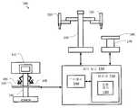
도 1은 일부 실시예에 따른 컴퓨터 지원 시스템(100)의 단순도이다. 도 1에 도시된 바와 같이, 컴퓨터 지원 시스템(100)은 하나 이상의 가동 또는 관절식 암(120)을 구비한 장치(110)를 포함하고 있다. 이러한 하나 이상의 관절식 암(120)의 각각은 하나 이상의 엔드 이펙터를 지원한다. 일부 예에서, 장치(110)는 컴퓨터 지원 수술 장치와 일치할 수 있다. 이러한 하나 이상의 관절식 암(120)은 관절식 암(120)의 적어도 하나의 말단부에 장착되는 하나 이상의 기기, 수술 기기, 이미징 장치 및/또는 그밖에 유사한 것에 대한 지지를 제공한다. 장치(110)는 장치(110)를 작동하기 위한 하나 이상의 마스터 컨트롤, 하나 이상의 관절식 암(120), 및/또는 엔드 이펙터를 포함할 수 있는 오퍼레이터 워크스테이션(도시되지 않음)에 더 결합될 수 있다. 일부 실시예에서, 장치(110) 및 오퍼레이터 워크스테이션은 캘리포니아, 서니베일의 인튜어티브 서지컬 인코퍼레이티드에 의해 판매되는 da Vinci®Surgical System에 상응할 수 있다. 일부 실시예에서, 다른 구성, 보다 적거나 많은 관절식 암, 및/또는 그밖의 유사한 것을 구비한 컴퓨터 지원 수술 장치가 옵션으로 컴퓨터 지원 시스템(100)과 함께 사용될 수 있다.1 is a simplified diagram of a
장치(110)는 인터페이스를 통해 제어 유닛(130)에 결합되어 있다. 이러한 인터페이스는 하나 이상의 무선 링크, 케이블, 커넥터, 및/또는 버스를 포함할 수 있고 하나 이상의 네트워크 스위칭 및/또는 라우팅 장치를 구비한 하나 이상의 네트워크를 더 포함할 수 있다. 제어 유닛(130)은 메모리(150)에 결합된 프로세서(140)를 포함하고 있다. 제어 유닛(130)의 동작은 프로세서(140)에 의해 제어된다. 제어 유닛(130)이 오직 하나의 프로세서(140)를 갖는 것으로 도시되어 있지만, 프로세서(140)는 제어 유닛(130) 내의 하나 이상의 중앙 처리 유닛, 멀티코어 프로세서, 마이크로프로세서, 마이크로컨트롤러, 디지털 신호 프로세서, 전계 프로그래머블 게이트 어레이(FPGA), 주문형 집적 회로(ASIC) 및/또는 그밖의 것을 나타낼 수 있다는 것을 이해해야 한다. 제어 유닛(130)은 컴퓨팅 장치에 더해진 독립형 서브시스템 및/또는 보드 또는 가상 머신으로서 구현될 수 있다. 일부 실시예에서, 제어 유닛은 오퍼레이터 워크스테이션의 일부로서 포함되고 및/또는 오퍼레이터 워크스테이션으로부터 떨어져 동작되지만 함께 동작될 수도 있다. 제어 유닛(130)과 같은 제어 유닛의 일부 예는 하나 이상의 프로세서(예를 들어, 프로세서(140))에 의해 실행될 때 이러한 하나 이상의 프로세서가 방법 400의 프로세스를 실행하도록 할 수 있는 실행가능한 코드를 포함하는 비임시, 유형, 기계 판독가능 매체를 포함할 수 있다.The
메모리(150)는 제어 유닛(130)에 의해 실행되는 소프트웨어 및/또는 제어 유닛(130)의 동작 동안 사용되는 하나 이상의 데이터 구조를 저장하는데 사용된다. 메모리(150)는 하나 이상 타입의 기계 판독가능 매체를 포함할 수 있다. 일부 공통 형태의 기계 판독가능 매체는 플로피 디스크, 플렉시블 디스크, 하드 디스크, 자기 테이프, 임의의 다른 자기 매체, CD-ROM, 임의의 다른 광학 매체, 펀치 카드, 페이퍼 테이프, 구멍의 패턴을 갖는 임의의 다른 물리적 매체, RAM, PROM, EPROM, FLASH-EPROM, 임의의 다른 메모리 칩 또는 카트리지, 및/또는 프로세서 또는 컴퓨터가 판독하도록 구성된 임의의 다른 매체를 포함할 수 있다.The memory 150 is used to store software and / or one or more data structures to be used during operation of the control unit 130 by the control unit 130. Memory 150 may include one or more types of machine-readable media. Some common types of machine-readable media include, but are not limited to, floppy disks, flexible disks, hard disks, magnetic tape, any other magnetic media, CD-ROMs, any other optical media, punch cards, paper tapes, ROM, a PROM, an EPROM, a FLASH-EPROM, any other memory chip or cartridge, and / or any other medium configured to be read by a processor or computer.
도시된 바와 같이, 메모리(150)는 장치(110)의 자율 및/또는 반자율 제어를 지원하는 모션 제어 애플리케이션(160)을 포함하고 있다. 모션 제어 애플리케이션(160)은 장치(110)로부터 위치, 모션, 및/또는 센서 정보를 수신하고, 수술 테이블 및/또는 이미징 장치와 같은 다른 장치에 대해 다른 제어 유닛과 위치, 모션, 및/또는 충돌 회피 정보를 교환하고, 및/또는 장치(110), 관절식 암(120), 및/또는 장치(110)의 엔드 이펙터에 대한 모션을 계획하고 및/또는 모션의 계획을 돕기 위한 하나 이상의 애플리케이션 프로그래밍 인터페이스(API)를 포함할 수 있다. 그리고 모션 제어 애플리케이션(160)이 소프트웨어 애플리케이션으로서 도시되어 있지만, 모션 제어 애플리케이션(160)은 하드웨어, 소프트웨어, 및/또는 하드웨어 및 소프트웨어의 조합을 사용하여 구현될 수 있다.As shown, the memory 150 includes a motion control application 160 that supports autonomous and / or semi-autonomous control of the
일부 실시예에서, 컴퓨터 지원 시스템(100)은 동작실 및/또는 조정실에서 발견될 수 있다. 그리고 컴퓨터 지원 시스템(100)이 2개의 관절식 암(120)을 갖는 오직 하나의 장치(110)를 포함하고 있지만, 컴퓨터 지원 시스템(100)은 장치(110)와 유사하고 및/또는 상이한 설계의 관절식 암 및/또는 엔드 이펙터를 갖는 임의의 수의 장치를 포함할 수 있다는 것을 당업자는 이해할 것이다. 일부 예에서, 이러한 장치의 각각은 보다 적거나 보다 많은 관절식 암 및/또는 엔드 이펙터를 포함할 수 있다.In some embodiments, the
컴퓨터 지원 시스템(100)은 수술 테이블(170)을 더 포함한다. 하나 이상의 관절식 암(120)과 같이, 수술 테이블(170)은 수술 테이블(170)의 베이스와 상대적인 테이블 상부(180)의 관절식 이동을 지원한다. 일부 예에서, 테이블 상부(180)의 관절식 이동은 테이블 상부(180)의 높이, 틸트, 슬라이드, 트렌델렌부르크 방향등을 변경하기 위한 서포트를 포함할 수 있다. 도시되지는 않았지만, 수술 테이블(170)은 테이블 상부(180)의 위치 및/또는 방향을 제어하기 위한 수술 테이블 명령 유닛과 같은 하나 이상의 제어 입력부를 포함할 수 있다. 일부 실시예에서, 수술 테이블(170)은 독일의 Trumpf Medical Systems GmbH에 의해 판매되는 수술 테이블의 하나 이상에 상응할 수 있다.The
수술 테이블(170)은 또한 상응하는 인터페이스를 통해 제어 유닛(130)에 결합되어 있다. 이러한 인터페이스는 하나 이상의 무선 링크, 케이블, 커넥터, 및/또는 버스를 포함할 수 있고, 하나 이상의 네트워크 스위칭 및/또는 라우팅 장치를 갖는 하나 이상의 네트워크를 더 포함할 수 있다. 일부 실시예에서, 수술 테이블(170)은 제어 유닛(130)과 상이한 제어 유닛에 결합될 수 있다. 일부 예에서, 모션 제어 애플리케이션(160)은 수술 테이블(170) 및/또는 테이블 상부(180)과 연관된 위치, 운동, 및/또는 다른 센서 정보를 수신하기 위한 하나 이상의 애플리케이션 프로그래밍 인터페이스(API)를 포함할 수 있다. 일부 예에서, 모션 제어 애플리케이션(160)은 수술 테이블(170) 및/또는 수술 상부(180)에 대한 모션을 계획하고 및/또는 계획하는 것을 도울 수 있다. 일부 예에서, 모션 제어 애플리케이션(160)은 관절식 암, 기기, 엔드 이펙터, 수술 테이블 구성요소 등의 이동, 조인트 및 링크의 운동 제한 범위를 피하여 관절식 암, 기기, 엔드 이펙터, 수술 테이블 구성요소등의 다른 운동을 보상하고, 내시경과 같은 뷰잉 장치를 조정하여 관심의 영역 및/또는 하나 이상의 기기 또는 엔드 이펙터를 뷰잉 장치의 시야 안에 유지 및/또는 배치하도록 구성된, 충돌 회피와 연관된 운동 계획에 기여할 수 있다. 일부 예에서, 모션 제어 애플리케이션(160)은 수술 테이블 명령 유닛을 사용함으로써 수술 테이블(170) 및/또는 테이블 상부(180)의 이동을 방지하는 것과 같이 하여 수술 테이블(170) 및/또는 테이블 상부(180)의 모션을 방지할 수 있다. 일부 예에서, 모션 제어 애플리케이션(160)은 레지스터 장치(110)와 수술 테이블(170) 사이의 기하학적 관계를 알도록 수술 테이블(170)과 함께 레지스터 장치(110)를 도울 수 있다. 일부 예에서, 기하학적 관계는 레지스터 장치(110) 및 수술 테이블(170)에 대해 유지되는 좌표 프레임들 사이에 병진 및/또는 하나 이상의 회전을 포함할 수 있다.The surgical table 170 is also coupled to the control unit 130 via a corresponding interface. Such an interface may further include one or more networks having one or more network switching and / or routing devices, which may include one or more wireless links, cables, connectors, and / or buses. In some embodiments, the surgical table 170 may be coupled to a control unit that is different from the control unit 130. Motion control application 160 includes one or more application programming interfaces (APIs) for receiving position, motion, and / or other sensor information associated with surgical table 170 and / or
제어 유닛(130)은 또한 인터페이스를 통해 오퍼레이터 워크스테이션(190)에 결합될 수 있다. 오퍼레이터 워크스테이션(190)은 관절식 암(120) 및 엔드 이펙터의 이동 및/또는 운전을 제어하기 위해 의사와 같은 운전자에 의해 사용될 수 있다. 관절식 암(120) 및 엔드 이펙터의 운전을 지원하기 위해, 오퍼레이터 워크스테이션(190)은 관절식 암(120) 및/또는 엔드 이펙터중 하나 이상의 적어도 일부의 영상을 표시하기 위한 디스플레이 시스템(192)을 포함하고 있다. 예를 들어, 디스플레이 시스템(192)은 관절식 암(120) 및/또는 엔드 이펙터가 사용되고 있을 때 이들을 운전자가 보는 것이 비현실적이고 및/또는 불가능할 때 사용될 수 있다. 일부 실시예에서, 디스플레이 시스템(192)은 관절직 암(120)중 하나, 또는 제3 관절식 암(도시되지 않음)에 의해 제어되는, 내시경과 같은, 비디오 포착 장치로부터 비디오 영상을 표시할 수 있다.The control unit 130 may also be coupled to the
오퍼레이터 워크스테이션(190)은 레지스터 장치(110), 관절식 암(120), 및/또는 이러한 관절식 암(120)에 장착된 엔드 이펙터를 운전하는데 사용될 수 있는 하나 이상의 입력 또는 마스터 컨트롤(195)을 가진 콘솔 워크스테이션을 더 포함할 수 있다. 이러한 입력 컨트롤(195)의 각각은 이들 자체의 관절식 암의 말단부에 결합되어 입력 컨트롤(195)의 이동은 오퍼레이터 워크스테이션(190)에 의해 검출되고 제어 유닛(130)에 통신될 수 있다. 향상된 인체공학을 제공하기 위해, 콘솔 워크스페이스는 또한 운전자가 입력 컨트롤(195)을 조작하는 동안 그들의 팔을 쉬게 할 수 있는 암 레스트(197)과 같은 하나 이상의 레스트를 포함할 수 있다. 일부 예에서, 디스플레이 시스템(192) 및 입력 컨트롤(195)은 관절식 암(120) 및/또는 이러한 관절식 암(120)에 장착된 엔드 이펙터를 원격조정하기 위해 운전자에 의해 사용될 수 있다. 일부 실시예에서, 장치(110), 오퍼레이터 워크스테이션(190), 및 제어 유닛(130)은 캘리포니아, 서니베일의 인튜어티브 서지컬 인코퍼레이티드에 의해 판매되는 da Vinci®Surgical System에 상응할 수 있다.The
일부 실시예에서, 다른 구성 및/또는 구조가 컴퓨터 지원 시스템(100)과 함께 사용될 수 있다. 일부 예에서, 제어 유닛(130)은 오퍼레이터 워크스테이션(190) 및/또는 장치(110)의 일부로서 포함될 수 있다. 일부 실시예에서, 컴퓨터 지원 시스템(100)은 수술실 및/또는 중재실에서 발견될 수 있다. 컴퓨터 지원 시스템(100)이 2개의 관절식 암(120)을 갖는 오직 하나의 장치(110)를 포함하고 있지만, 당업자중 하나는 컴퓨터 지원 시스템(100)이 장치(110)와 유사하고 및/또는 상이한 설계의 관절식 암 및/또는 엔드 이펙터를 갖는 임의의 수의 장치를 포함할 수 있다는 것을 이해할 것이다. 일부 예에서, 이러한 장치의 각각은 보다 적거나 많은 관절식 암(120) 및/또는 엔드 이펙터를 포함할 수 있다. 추가로, 장치(110)에 부착될 수 있는 추가의 암을 제어하는 추가의 워크스테이션(190)이 존재할 수 있다. 또한, 일부 실시예에서, 워크 스테이션(190)은 수술 테이블(170)을 제어하기 위한 컨트롤을 가질 수 있다.In some embodiments, other configurations and / or structures may be used with the
도 2는 일부 실시예에 따른 컴퓨터 지원 시스템(200)을 도시하는 단순도이다. 예를 들어, 컴퓨터 지원 시스템(200)은 컴퓨터 지원 시스템(100)과 일치할 수 있다. 도 2에 도시된 바와 같이, 컴퓨터 지원 시스템(200)은 하나 이상의 관절식 암을 갖는 컴퓨터 지원 장치(210) 및 수술 테이블(280)을 포함하고 있다. 도 2에는 도시되어 있지 않지만, 컴퓨터 지원 장치(210) 및 수술 테이블(280)은 하나 이상의 인터페이스 및 하나 이상의 제어 유닛을 사용하여 함께 결합될 수 있어서, 적어도 수술 테이블(280)에 대한 운동학 정보가 컴퓨터 지원 장치(210)의 관절식 암의 모션을 실행하는데 사용되는 모션 제어 애플리케이션에 알려진다.2 is a simplified diagram illustrating a
컴퓨터 지원 장치(210)는 다양한 링크 및 조인트를 포함하고 있다. 도 2의 실시예에서, 컴퓨터 지원 장치는 일반적으로 3개의 상이한 세트의 링크 및 조인트로 분리된다. 먼저 모바일 또는 환자측 카트(215)의 인접 단부에 셋업 구조부(220)가 있다. 이러한 셋업 구조부의 말단부에는 관절식 암을 형성하는 일련의 링크 및 셋업 조인트(240)가 결합되어 있다. 그리고 이러한 셋업 조인트(240)의 말단부에는 다관절 매니퓰레이터(260)가 결합되어 있다. 일부 예에서, 일련의 셋업 조인트(240) 및 매니퓰레이터(260)는 관절식 암(120)중 하나에 대응할 수 있다. 그리고 컴퓨터 지원 장치가 오직 하나의 일련의 셋업 조인트(240) 및 상응하는 매니퓰레이터(260)를 갖는 것으로 도시되어 있지만, 당업자는 컴퓨터 지원 장치가 하나 보다 많은 일련의 셋업 조인트(240) 및 상응하는 매니퓰레이터(260)를 포함할 수 있어서 컴퓨터 지원 장치는 다수의 관절식 암을 장착할 수 있음을 이해할 것이다.The computer aided
도시된 바와 같이, 컴퓨터 지원 장치(210)는 이동 카트(215)에 장착되어 있다. 이러한 이동 카트(215)에 의해 컴퓨터 지원 장치(210)는 컴퓨터 지원 장치를 수술 테이블(180)에 근접하여 보다 더 잘 위치지정하도록 수술실 사이에서 또는 수술실 안에서와 같이 위치 이동될 수 있다. 셋업 구조부(220)는 이동 카트(215)에 장착되어 있다. 도 2에 도시된 바와 같이, 셋업 구조부(220)는 컬럼 링크(221, 222)를 포함하는 2파트 컬럼을 포함하고 있다. 컬럼 링크(222)의 상단부 또는 말단부에는 쇼울더 조인트(223)가 결합되어 있다. 쇼울더 조인트(223)에는 붐 링크(224, 225)를 포함하는 2-파트 붐이 결합되어 있다. 붐 링크(225)의 말단부에는 팔목 조인트(226)가 있고, 팔목 조인트(226)에는 암 장착 플랫폼(227)이 결합되어 있다.As shown, the computer aided
셋업 구조부(220)의 링크 및 조인트는 암 장착 플랫폼(227)의 위치 및 방향(즉, 포즈)을 변경하기 위한 다양한 자유도를 포함하고 있다. 예를 들어, 2-파트 컬럼이 축(232)을 따라 쇼울더 조인트(223)를 이동시킴으로써 암 장착 플랫폼(227)의 높이를 조정하는데 사용될 수 있다. 이러한 암 장착 플랫폼(227)은 쇼울더 조인트(223)를 사용하여 이동 카트(215), 2-파트 컬럼, 및 축(232)에 대해 추가로 회전될 수 있다. 암 장착 플랫폼(227)의 수평 위치 역시 2-파트 붐을 사용하여 축(234)를 따라 조정될 수 있다. 그리고 암 장착 플랫폼(227)의 방향 역시 팔목 조인트(226)를 사용하여 암 장착 플랫폼 배향 축(236)에 대해 회전함으로써 조정될 수 있다. 따라서, 셋업 구조부(220)의 링크 및 조인트의 모션 리미트에 의해, 암 장착 플랫폼(227)의 위치는 2-파트 컬럼을 사용하여 이동 카트(215) 위로 수직으로 조정될 수 있다. 암 장착 플랫폼(227)의 위치 역시 각각 2-파트 붐 및 쇼울더 조인트(223)를 사용하여 이동 카트(215)에 대해 방사형으로 그리고 각지게 조정될 수 있다. 그리고 암 장착 플랫폼(227)의 각도 방향 역시 팔목 조인트(226)를 사용하여 변경될 수 있다.The links and joints of the
암 장착 플랫폼(227)은 하나 이상의 관절식 암을 위한 장착점으로서 사용될 수 있다. 이동 카트(215)에 대해 암 장착 플랫폼(227)의 높이, 수평 위치, 및 방향을 조정하는 기능은 수술 또는 시술이 시행되는 이동 카트(215) 근방에 위치된, 환자와 같은, 작업 공간에 대해 하나 이상의 관절식 암을 위치지정하고 배향하기 위한 유연한 셋업 구조부를 제공한다. 예를 들어, 암 장착 플랫폼(227)이 환자 위에 위치지정되어 다양한 관절식 암 및 이들의 상응하는 매니퓰레이터 및 기기가 환자에게 시술을 실행하기에 충분한 범위의 운동을 가질 수 있다. 도 2는 제1 셋업 또는 플렉스 조인트(242)를 사용하여 암 장착 플랫폼(227)에 결합된 단일 관절식 암을 도시하고 있다. 그리고, 오직 하나의 관절식 암이 도시되어 있지만, 당업자는 다수의 관절식 암이 추가 제1 셋업 조인트를 사용하여 암 장착 플랫폼(227)에 결합될 수 있음을 이해할 것이다.The
제1 셋업 조인트(242)는 환자측 카트(215)에 최근접한 관절식 암의 셋업 조인트(240) 섹션의 최근접부를 형성한다. 셋업 조인트(240)는 일련의 조인트 및 링크를 더 포함할 수 있다. 도 2에 도시된 바와 같이, 셋업 조인트(240)는 적어도, (뚜렷이 도시되지 않은) 하나 이상의 조인트를 통해 결합된 링크(244, 246)를 포함할 수 있다. 셋업 조인트(240)의 조인트 및 링크는 제1 셋업 조인트(242)를 사용하여 축(252)에 대해 암 장착 플랫폼(227)에 상대적으로 셋업 조인트(240)를 회전시키고, 제1 셋업 조인트(242)와 링크(246) 사이의 방사형 또는 수평 거리를 조정하고, 축(254)을 따라 배향 플랫폼에 상대적으로 링크(246)의 말단부에서 매니퓰레이터 마운트(262)의 높이를 조정하고, 매니퓰레이터 마운트(262)를 축(254)에 대해 회전시키는 기능을 포함하고 있다. 일부 예에서, 셋업 조인트(240)는 암 장착 플랫폼(227)에 상대적으로 매니퓰레이터 마운트(262)의 포즈를 변경하기 위한 추가 자유도를 허용하는 추가적인 조인트, 링크 및 축을 더 포함할 수 있다.The first set-up joint 242 forms the proximal portion of the set-up joint 240 section of the articulated arm closest to the patient-
매니퓰레이터(260)는 매니퓰레이터 마운트(262)를 통해 셋업 조인트(240)의 말단부에 결합되어 있다. 매니퓰레이터(260)는 매니퓰레이터(260)의 말단부에 장착된 기기 캐리지(268)와 함께 추가 조인트(264) 및 링크(266)를 포함하고 있다. 기기 또는 매니퓰레이터 기기(270)가 기기 캐리지(268)에 장착되어 있다. 이러한 기기(270)는 삽입축을 따라 정렬된 샤프트(272)를 포함하고 있다. 샤프트(272)는 보통 매니퓰레이터(260)과 연관된 원격 운동 중심(274)을 통해 통과되도록 정렬되어 있다. 운동의 원격 운동 중심(274)의 위치는 보통 매니퓰레이터 마운트(262)에 대해 고정 병진 관계로 유지되어서 매니퓰레이터(260)의 조인트(264)의 동작에 의해 운동의 원격 운동 중심(274)에 대해 샤프트(272)가 회전한다. 이러한 실시예에 따라, 매니퓰레이터 마운트(262)에 대한 운동의 원격 운동 중심(274)의 고정 병진 관계는 매니퓰레이터(262)의 조인트(264) 및 링크(266)의 물리적 제약을 사용하여, 조인트(264)에 대해 허용된 운동에 대한 소프트웨어 제약을 사용하여, 및/또는 이 둘의 조합에 의해 유지된다. 조인트 및 링크의 물리적 제약을 사용하여 조작되는 원격 운동 중심을 사용하는 컴퓨터 지원 수술 장치의 대표적인 예가 2013년 5월 13일에 출원된, "Redundant Axis and Degree of Freedom for Hardware-Constrained Remote Center Robotic Manipulator" 표제의 미국 특허 출원 번호 13/906,888에 기술되어 있고, 소프트웨어 제약에 의해 조작되는 운동의 원격 센서를 사용하여 컴퓨터 지원 수술 장치의 대표적인 실시예가 2005년 5월 10일에 출원된, "Software Center and Highly Configurable Robotic Systems for Surgery and Other Uses" 표제의 미국 특허 번호 8,004,229에 기술되어 있고, 이들의 내용은 그 전체가 여기에 언급되어 통합되어 있다. 일부 예에서, 원격 운동 중심(274)은 샤프트(272)가 환자(278) 안으로 삽입될 때 환자(278)의 수술 포트, 신체 개구, 도는 절개 사이트의 위치에 상응할 수 있다. 원격 운동 중심(274)이 수술 포트에 상응하기 때문에, 기기(270)가 사용될 때에, 원격 운동 중심(274)은 환자(278)에 대해 고정된 상태가 되어 운동의 원격 운동 중심(274)에서 환자(278)의 인체에 대한 스트레스를 제한한다. 일부 예에서, 샤프트(272)는 옵션으로 수술 포트에 위치된 캐뉼라(도시되지 않음)를 통과할 수 있다. 일부 예에서, 비교적 더 큰 샤프트 또는 가이드 튜브 외경(예를 들어, 4-5 mm 이상)를 갖는 기기는 캐뉼라를 사용하여 신체 개구를 통과할 수 있고, 이러한 캐뉼라는 비교적 더 작은 샤프트 또는 가이트 튜브 외경(예를 들어, 2-3 mm 이하)을 갖는 기기에 옵션으로 생략될 수 있다.
샤프트(272)의 말단부에 엔드 이펙터(276)가 있다. 조인트(264) 및 링크(266)으로 인한 매니퓰레이터(260)의 자유도에 의해 적어도 매니퓰레이터 마운트(262)에 대해 샤프트(272) 및/또는 엔드 이펙터(276)의 롤, 피치, 및 요를 제어할 수 있다. 일부 예에서, 매니퓰레이터(260)의 자유도는 기기 캐리지(268)를 사용하여 샤프트(272)를 전진 및/또는 후퇴시키는 기능을 더 포함하여 엔드 이펙터(276)는 삽입축을 따라 그리고 운동의 원격 운동 중심(274)에 상대적으로 전진 및/또는 후퇴될 수 있다. 일부 예에서, 매니퓰레이터(260)는 캘리포니아, 서니베일의 인튜어티브 서지컬 인코퍼레이티드에 판매되는 da Vinci®Surgical System와 함께 사용하기 위한 매니퓰레이터와 일치할 수 있다. 일부 예에서, 기기(270)는 내시경과 같은 이미징 장치, 그립퍼, 소작 또는 메스와 같은 수술 기기 등일 수 있다. 일부 예에서, 엔드 이펙터(276)는 샤프트(272)의 말단부에 대해 엔드 이펙터(276)의 일부의 추가 국부적인 조작을 가능하게 하는 롤, 피치, 요소, 그립 등과 같은 추가 자유도를 포함할 수 있다.An
수술 또는 다른 의료 시술 동안, 환자(278)는 보통 수술 테이블(280) 위에 위치되어 있다. 수술 테이블(280)은 테이블 베이스(282)가 이동 카트(215)에 근접하여 위치된 상태로 테이블 베이스(282) 및 테이블 상부(284)를 포함하여 기기(270) 및/또는 엔드 이펙터(276)는 기기(270)의 샤프트(272)가 환자(278)의 신체 개구에 삽입되어 있는 동안 컴퓨터 지원 장치(210)에 의해 조작될 수 있다. 수술 테이블(280)은 테이블 베이스(282)와 테이블 상부(284) 사이에 하나 이상의 조인트 또는 링크를 포함하는 관절식 구조부(290)를 더 포함하여, 테이블 베이스(280)에 대한, 테이블 상부(284), 그래서 환자(278)의 상대 위치가 제어될 수 있다. 일부 예에서, 관절식 구조부(290)는 테이블 상부(284) 위의 포인트에 위치될 수 있는 가상 규정된 테이블 운동 이소(iso) 센터(286)에 상대적으로 테이블 상부(284)가 제어되도록 구성될 수 있다. 일부 예에서, 이소센터(286)는 환자(278)의 내부에 위치될 수 있다. 일부 예에서, 이소센터(286)는 원격 운동 중심(274)에 상응하는 신체 개구와 같은, 신체 개구중 하나에 또는 근방에 환자의 인체 벽과 연어될 수 있다.During surgery or other medical procedures, the
도 2에 도시된 바와 같이, 관절식 구조부(290)는 테이블 상부(824)가 테이블 베이스(282)에 상대적으로 상승 및/또는 하강될 수 있도록 높이 조정 조인트(292)를 포함하고 있다. 관절식 구조부(290)는 이소센터(286)에 대해 테이블 상부(284)의 틸트(296) 및 트렌델렌부르크(296) 방향 모두를 변경하기 위해 조인트 및 링크를 더 포함하고 있다. 이러한 틸트(294)에 의해 테이블 상부(284)가 좌우로 기울어질 수 있어서 환자(278)의 좌측 또는 우측이 환자(278)의 타측에 대해 상방으로 (즉, 테이블 상부(284)의 종방향으로, 두개골-미골부, 또는 상하(두개골-미골부) 축에 대해) 회전될 수 있다. 트렌델렌부르크(296)에 의해 테이블 상부(284)는 회전되어 환자(278)의 발이 상승되거나(트렌델렌부르크) 환자(278)의 머리가 상승된다(역 트렌델렌부르크). 일부 예에서, 틸트(294) 및/또는 트렌델렌부르크(296) 회전은 이소센터(286)에 대한 회전을 발생시키도록 조정될 수 있다. 관절식 구조부(290)는 도 2에 도시된 바와 같이 대략 좌측 및/또는 우측 운동으로 테이블 상부(284)가 테이블 베이스(282)에 대해 종방향(두개골-미골부) 축 전후를 따라 미끄러지도록 추가 링크 및 조인트(298)를 더 포함하고 있다.2, the articulated
도 7a 내지 도 7g는 여기에 기술된 통합 컴퓨터 지원 장치 및 가동 수술 테이블 특징부를 포함하는 다양한 컴퓨터 지원 장치 시스템 구조를 도시하는 단순 개략도이다. 이러한 다양한 도시된 시스템 구성요소는 여기에 기술된 원리에 따르고 있다. 이러한 도면에서, 구성요소는 이해를 위해 단순화되어 있고, 개별적인 링크, 조인트, 매니퓰레이터, 기기, 엔드 이펙터 등과 같은 다양한 세부요소는 도시되어 있지 않지만, 이들은 다양한 구성요소에 포함되어 있는 것으로 이해해야 한다.FIGS. 7A-7G are simplified schematic diagrams illustrating various computer-assisted device system configurations including the integrated computer aided device and the movable surgical table features described herein. These various illustrated system components are in accordance with the principles described herein. In the drawings, components are simplified for clarity and various subcomponents such as individual links, joints, manipulators, instruments, end effectors, etc., are not shown, but should be understood to be included in the various components.
이러한 구조에서, 하나 이상의 수술 기기 또는 기기의 클러스터와 연관된 캐뉼라는 도시되어 있지 않고, 캐뉼라 및 다른 기기 가이드 장치가 비교적 더 큰 샤프트 또는 가이드 튜브 외경(예를 들어, 4-5 mm 이상)을 갖는 기기 또는 기기 클러스터에 옵션으로 사용될 수 있고 비교적 더 작은 샤프트 또는 가이드 튜브 외경(예를 들어, 2-3 mm 이하)을 갖는 기기에 대해 옵션으로 생략될 수 있다는 것을 이해해야 한다.In such a configuration, no cannula associated with one or more surgical instruments or clusters of instruments is shown, and cannula and other instrument guide devices may be used with relatively large shafts or guide tube outer diameters (e.g., greater than 4-5 mm) Or may optionally be omitted for appliances having a comparatively smaller shaft or guide tube outer diameter (e.g., 2-3 mm or less) that can be optionally used in a device cluster.
또한, 이러한 구조에서, 원격조정 매니퓰레이터는 수술 동안 하드웨어 제약(예를 들어, 고정 교차 기기 피치, 요, 및 롤 축) 또는 소프트웨어 제약(예를 들어, 소프트웨어 제약된 교차 기기 피치, 요, 롤 축)을 사용함으로써 원격 운동 중심을 규정하는 매니퓰레이터를 포함하는 것으로 이해해야 한다. 이러한 기기 회전축의 하이브리드가 규정되는 것(예를 들어, 하드웨어 제약된 롤 축 및 소프트웨어 제약된 피치 및 요 축) 역시 가능하다. 또한, 일부 매니퓰레이터 시술 동안 어떤 회전의 수술 기기 축도 규정하고 제약할 수 없고, 일부 매니퓰레이터는 시술 동안 오직 하나 이상의 회전의 기기 축을 규정하고 제약할 수 있다.In addition, in such a configuration, the remote control manipulator may be configured to be operable during operation by hardware constraints (e.g., fixed cross device pitch, yaw, and roll axes) or software constraints (e.g., software constrained cross device pitch, As used herein, includes a manipulator that defines a center of exertion by use of a manipulator. It is also possible that the hybrids of such machine rotation axes are defined (e.g., hardware constrained roll axes and software constrained pitches and yaw axes). In addition, during some manipulator procedures, the surgical instrument axis of any rotation can not be specified and constrained, and some manipulators can define and constrain only one or more machine axis of rotation during the procedure.
도 7a는 가동 수술 테이블(1100) 및 단일 기기 컴퓨터 지원 장치(1101a)를 도시하고 있다. 수술 테이블(1100)은 가동 테이블 상부(1102) 및 말단부에서 테이블 상부(1102)를 지지하기 위해 기계적으로 접지된 근접 베이스(1104)로부터 뻗은 테이블 지지 구조부(1103)를 포함하고 있다. 일부 예에서, 수술 테이블(1100)은 수술 테이블(170 및/또는 280)과 일치할 수 있다. 컴퓨터 지원 장치(1101a)는 원격조정 매니퓰레이터 및 단일 기기 어셈블리(1105a)를 포함하고 있다. 컴퓨터 지원 장치(1101a)는 또한 근접 베이스(1107a)에서 기계적으로 접지되어 있고 말단부에서 매니퓰레이터 및 기기 어셈블리(1105a)를 지지하도록 뻗은 지지 구조부(1106a)를 포함하고 있다. 지지 구조부(1106a)는 어셈블리(1105a)가 수술 테이블(1100)에 대해 이동되고 다양한 고정 자세로 유지될 수 있도록 구성되어 있다. 베이스(1107a)는 옵션으로 수술 테이블(1100)에 대해 영구 고정되거나 이동가능하다. 수술 테이블(1100) 및 컴퓨터 지원 장치(1101a)는 여기에 기술된 바와 같이 함께 작동한다.7A shows a movable surgical table 1100 and a single device computer aided
도 7a는 또한 상응하는 지지 구조부(1106b)에 의해 지지되는 상응하는 개별적인 원격조정 매니퓰레이터 및 단일-기기 어셈블리(1105b)를 갖는, 2, 3, 4, 5개 이상의 개별적인 컴퓨터 지원 장치가 포함될 수 있다는 것을 도시한 옵션의 제2 컴퓨터 지원 장치(1101b)를 도시하고 있다. 컴퓨터 지원 장치(1101b)는 기계적으로 접지되어 있고, 어셈블리(1105b)는 컴퓨터 지원 장치(110a)와 유사한 포즈를 갖고 있다. 수술 테이블(1100) 및 컴퓨터 지원 장치(1101a, 1101b)는 함께 멀티-기기 수술 시스템을 만들고, 이들은 여기에 기술된 대로 함께 작동한다. 일부 예에서, 컴퓨터 지원 장치(110a 및/또는 1101b)는 컴퓨터 지원 장치(110 및/또는 210)와 일치할 수 있다.Figure 7a also shows that two, three, four, five or more individual computer aided devices may be included having corresponding single remote control manipulators and single-
도 7b에 도시된 바와 같이, 다른 가동 수술 테이블(1100) 및 컴퓨터 지원 장치(1111)가 도시되어 있다. 컴퓨터 지원 장치(1111)는 대표적인 매니퓰레이터 및 기기 어셈블리(1105a, 1105b)에 의해 도시된 바와 같이, 2, 3, 4, 5개 이상의 개별적인 원격조정 매니퓰레이터 및 단일-기기 어셈블리를 포함하는 멀티-기기 장치이다. 컴퓨터 지원 장치(1111)의 어셈블리(1105a, 1105b)는 결합 지지 구조부(1112)에 의해 지지되어, 어셈블리(1105a, 1105b)는 수술 테이블(1100)에 대해 그룹으로서 함께 이동되고 포즈를 가질 수 있다. 컴퓨터 지원 장치(1111)의 어셈블리(1105a, 1105b)는 또한 상응하는 개별적인 지지 구조부(1113a, 1113b)에 의해 각각 지지되어, 각각의 어셈블리(1105a, 1105b)는 수술 테이블(1100) 및 하나 이상의 다른 어셈블리(1105a, 1105b)에 대해 개별적으로 이동되고 포즈를 가질 수 있다. 각각의 멀티-기기 수술 시스템 구조부의 예는 인튜어티브 서지컬 인코퍼레이티드에 의해 판매되는, da Vinci Si® Surgical System 및 da Vinci® Xi™ Surgical System이다. 수술 테이블(1100) 및 수술 매니퓰레이터 시스템(1111)은 여기에 기술된 바와 같이 함께 작동한다. 일부 예에서, 컴퓨터 지원 장치(1111)는 컴퓨터 지원 장치(110 및/또는 210)와 일치한다.As shown in FIG. 7B, another movable surgical table 1100 and a computer aided
도 7a 및 도 7b의 컴퓨터 지원 장치는 각각 플로어에 기계적으로 접지되어 도시되어 있다. 그러나, 이러한 하나 이상의 컴퓨터 지원 장치는 옵션으로 벽 또는 천장에 기계적으로 접지될 수 있고 이러한 벽 또는 천장에 대해 영구 고정되거나 이동가능할 수 있다. 일부 예에서, 컴퓨터 지원 장치는 컴퓨터 지원 시스템의 지지 베이스가 수술 테이블에 대해 이동될 수 있도록 하는 트랙 또는 격자 시스템을 사용하여 벽 또는 천장에 장착될 수 있다. 일부 예에서, 하나 이상의 고정되거나 해제가능한 장착 클램프는 각각의 지지 베이스를 이러한 트랙 또는 격자 시스템에 장착하는데 사용될 수 있다. 도 7c에 도시된 바와 같이, 컴퓨터 지원 장치(1121a)는 벽에 기계적으로 접지되고, 컴퓨터 지원 장치(1121b)는 천장에 기계적으로 접지되어 있다.The computer aided devices of Figures 7a and 7b are shown mechanically grounded on the floor, respectively. However, such one or more computer aided devices may optionally be mechanically grounded to a wall or ceiling and permanently fixed or movable relative to such wall or ceiling. In some instances, the computer aided device may be mounted on a wall or ceiling using a track or lattice system that allows the support base of the computer aided system to be moved relative to the surgical table. In some instances, one or more fixed or releasable mounting clamps may be used to mount each of the support bases to such track or lattice system. As shown in Fig. 7C, the computer aided
추가로, 컴퓨터 지원 장치는 가동 수술 테이블(1100)을 통해 간접적으로 기계적으로 접지될 수 있다. 도 7d에 도시된 바와 같이, 컴퓨터 지원 장치(1131a)는 수술 테이블(1100)의 테이블 상부(1102)에 결합되어 있다. 컴퓨터 지원 장치(1131a)는 도 7d에 점선 구조부로 도시한 바와 같이, 테이블 지지 구조부(1103) 또는 테이블 베이스(1104)와 같은, 수술 테이블(1100)의 다른 부분에 옵션으로 결합될 수 있다. 테이블 상부(1102)가 테이블 지지 구조부(1103) 또는 테이블 베이스(1104)에 대해 이동할 때, 컴퓨터 지원 장치(1131)는 마찬가지로 테이블 지지 구조부(1103) 또는 테이블 베이스(1104)에 대해 이동한다. 그러나, 컴퓨터 지원 장치(1131a)가 테이블 지지 구조부(1103) 또는 테이블 베이스(1104)에 결합될 때, 컴퓨터 지원 장치(1131a)의 베이스는 테이블 상부(1102)가 이동할 때 그라운드에 대해 고정된 상태로 있게 된다. 테이블 운동이 발생함에 따라, 환자에게 기기가 삽입되는 신체 개구 역시 이동할 수 있는데, 그 이유는 환자의 신체가 이동하고 테이블 상부(1102)에 대해 신체 위치를 변경할 수 있기 때문이다. 따라서, 컴퓨터 지원 장치(1131a)가 테이블 상부(1102)에 결합되는 실시예에 있어서, 테이블 상부(1102)는 로컬 기계 그라운드로서 기능하고, 신체 개구는 테이블 상부(1102)에 대해 이동하고, 컴퓨터 지원 장치(1131a)에 대해서도 이동한다. 도 7d는 또한 멀티-기기 시스템을 생성하기 위해 컴퓨터 지원 장치(1131a)와 마찬가지로 구성된, 제2 컴퓨터 지원 장치(1131b)가 옵션으로 추가될 수 있다는 것을 보여주고 있다. 이러한 수술 테이블에 결합된 하나 이상의 컴퓨터 지원 장치를 포함하는 시스템은 여기에 개시된 바와 같이 작동한다.In addition, the computer aided device may be mechanically grounded indirectly via the movable surgical table 1100. As shown in FIG. 7D, the computer aided
일부 실시예에서, 동일하거나 하이브리드 기계적 접지를 갖는 컴퓨터 지원 장치의 다른 조합이 가능하다. 예를 들어, 플로어에 기계적으로 접지된 하나의 컴퓨터 지원 장치 및, 수술 테이블을 통해 이러한 플로어에 기계적으로 접지된 제2 컴퓨터 지원 장치를 포함할 수 있다. 이러한 하이브리드 기계적 접지 시스템은 여기에 개시된 바와 같이 작동한다.In some embodiments, other combinations of computer aided devices having the same or hybrid mechanical ground are possible. For example, it may include one computer-assisted device mechanically grounded to the floor and a second computer-assisted device mechanically grounded to such floor through a surgical table. Such a hybrid mechanical grounding system operates as described herein.
본 특징은 또한 2개 이상의 수술 기기가 단일 신체 개구를 통해 신체에 들어가는 단일-신체 개구 시스템을 포함하고 있다. 이러한 시스템의 예는 여기에 언급되어 통합된, 2010년 8월 12일에 출원된, "Surgical System Instrument Mounting" 표제의 미국 특허 번호 8,852,208 및, 2007년 6월 13일에 출원된 "Minimally Invasive Surgical System" 표제의 미국 특허 번호 9,060,678에서 볼 수 있다. 도 7e는 상술된 바와 같이 수술 테이블(1100)과 함께 원격조정 멀티-기기 컴퓨터 지원 장치(1141)를 도시하고 있다. 2개 이상의 기기(1142)는 각각 상응하는 매니퓰레이터(1143)에 결합되어 있고 기기(1142) 및 기기 매니퓰레이터(1143)의 클러스터는 시스템 매니퓰레이터(1145)에 의해 함께 이동한다. 이러한 시스템 매니퓰레이터(1144)는 시스템 매니퓰레이터(1144)가 이동되고 다양한 포즈에서 고정될 수 있도록 하는 지지 어셈블리(1145)에 의해 지지된다. 지지 어셈블리(1145)는 상기 설명과 일치하는 베이스(1146)에 기계적으로 접지되어 있다. 2개 이상의 기기(1142)는 단일 신체 개구에서 환자에게 삽입된다. 옵션으로, 기기(1142)는 단일 가이드 튜브를 통해 함께 뻗고, 가이드 튜브는 옵션으로, 상술된 문헌에서 기술된 바와 같이, 캐뉼라를 통해 뻗어 있다. 컴퓨터 지원 장치(1141) 및 수술 테이블(1100)은 여기에 기술된 바와 같이 함께 작동한다.This feature also includes a single-body opening system in which two or more surgical instruments enter the body through a single body opening. Examples of such systems are described in U.S. Patent No. 8,852,208 entitled " Surgical System Instrument Mounting ", filed on August 12, 2010, incorporated herein by reference, and "Minimally Invasive Surgical System "U.S. Patent No. 9,060,678. 7E illustrates a remote-controlled multi-machine computer aided
도 7f는 옵션으로 테이블 상부(1102), 테이블 지지 구조부(1103), 또는 테이블 베이스(1104)에 결합되어, 수술 테이블(1100)을 통해 기계적으로 접지된 다른 멀티-기기, 단일 신체 개구 컴퓨터 지원 장치(1151)를 도시하고 있다. 도 7d에 대한 상기 설명 역시 도 7f에 도시된 기계적 접지 옵션에 적용된다. 컴퓨터 지원 장치(1151) 및 수술 테이블(1100)은 여기에 기술된 바와 같이 함께 작동한다.Figure 7f illustrates another multi-device, a single body opening computer aided device (not shown) coupled mechanically to the
도 7g는 하나 이상의 원격조정 멀티-기기, 단일 신체 개구 컴퓨터 지원 장치(1161) 및 하나 이상의 원격조정 단일-기기 컴퓨터 지원 장치(1162)가 여기에 기술된 바와 같이 수술 테이블(1100)과 함께 작동하도록 결합될 수 있음을 도시하고 있다. 컴퓨터 지원 장치(1161, 1162)의 각각은 직접 또는 다른 구조부를 통해, 여기에 기술된 다양한 방식으로 기계적으로 접지될 수 있다.FIG. 7G illustrates an exemplary embodiment of one or more remote control multi-devices, a single body opening computer aided
도 3은 일부 실시예에 따른 컴퓨터 지원 의료 시스템의 운동학 모델(300)의 단순도이다. 도 3에 도시된 바와 같이, 운동학 모델(300)은 많은 소스 및/또는 장치와 연관된 운동학 정보를 포함할 수 있다. 이러한 운동학 정보는 컴퓨터 지원 의료 장치 및 수술 테이블의 링크 및 조인트에 대한 공지된 운동학 모델에 기초할 수 있다. 이러한 운동학 정보는 또한 컴퓨터 지원 의료 장치 및 수술 테이블의 조인트의 위치 및/또는 방향과 연관된 정보에 기초할 수 있다. 일부 예에서, 이러한 조인트의 위치 및/또는 방향과 연관된 정보는 프리즘 조인트의 선형 위치 및 회전 조인트의 회전 위치를 측정하는, 인코더와 같은, 하나 이상의 센서로부터 유도될 수 있다.3 is a simplified diagram of a
이러한 운동학 모델(300)은 다수의 좌표 프레임 또는 좌표계 및, 좌표 프레임의 하나로부터 좌표 프레임의 다른 것으로 위치 및/또는 방향을 변환하기 위한 동종 변환과 같은 변환을 포함하고 있다. 일부 예에서, 운동학 모델(300)은 도 3에 포함된 변환 링크에 의해 표시된 순방향 및/또는 반전/역방향 변환을 구성함으로써 좌표 프레임중 임의의 다른 것에서 좌표 프레임중 하나의 위치 및/또는 방향의 순방향 및/또는 역방향 맵핑을 허용하도록 사용될 수 있다. 일부 예에서, 변환이 행렬 형태로 동종 변환으로서 모델화될 때, 이러한 구성은 행렬 승산을 사용하여 달성될 수 있다. 일부 실시예에서, 시스템은 좌표 기준 프레임을 이러한 운동학 체인의 하나 이상의 포인트에 부착하고 운동학 모델(300)의 하나의 기준 프레임으로부터 다른 프레임으로 변환하기 위해 Denavit-Hartenberg 파라미터 및 컨벤션을 사용할 수 있다. 일부 실시예에서, 운동학 모델(300)은 도 2의 컴퓨터 지원 장치(210) 및 수술 테이블(280)의 운동학 관계를 모델화하는데 사용될 수 있다.This
운동학 모델(300)은 수술 테이블(170) 및/또는 수술 테이블(280)과 같은, 수술 테이블의 위치 및/또는 방향을 모델화하는데 사용될 수 있는 테이블 베이스 좌표 프레임(305)을 포함하고 있다. 일부 예에서, 이러한 테이블 베이스 좌표 프레임(305)은 수술 테이블과 연관된 기준점 및/또는 방향에 대한 수술 테이블의 다른 점을 모델화하는데 사용될 수 있다. 일부 예에서, 이러한 기준점 및/또는 방향은 테이블 베이스(282)와 같은, 수술 테이블의 테이블 베이스와 연관될 수 있다. 일부 예에서, 테이블 베이스 좌표 프레임(305)은 컴퓨터 지원 시스템을 위한 글로벌 좌표 프레임으로서 사용되기에 적합할 수 있다.The
운동학 모델(300)은 테이블 상부(284)와 같은, 수술 테이블의 테이블 상부를 나타내는 좌표 프레임에서의 위치 및/또는 방향을 모델화하는데 사용될 수 있는 테이블 상부 좌표 프레임(310)을 더 포함하고 있다. 일부 예에서, 테이블 상부 좌표 프레임(310)은 회전 센터 또는 이소센터(286)와 같은, 테이블 상부의 이소 센터에 센터링될 수 있다. 일부 예에서, 테이블 상부 좌표 프레임(310)의 z축은 수술 테이블이 놓인 표면 또는 플로어에 대해 수직으로 및/또는 테이블 상부의 표면에 직교하는 방향을 가질 수 있다. 일부 예에서, 테이블 상부 좌표 프레임(310)의 x축과 y축은 테이블 상부의 종방향(상하) 및 측방향(좌우) 주축을 포착하도록 배향될 수 있다. 일부 예에서, 테이블 베이스-테이블 상부 좌표 변환(315)은 테이블 상부 좌표 프레임(310)과 테이블 베이스 좌표 프레임(305) 상의 위치 및/또는 방향을 맵핑하는데 사용될 수 있다. 일부 예에서, 관절식 구조부(290)와 같은, 수술 테이블의 관절식 구조부의 하나 이상의 운동학 모델은 과거 및/또는 현재 조인트 센서 판독값과 함께 테이블 베이스-테이블 상부 좌표 변환(315)을 결정하는데 사용된다. 일부 예에서, 도 2의 실시예와 일치하여, 테이블 베이스-테이블 상부 좌표 변환(315)이 수술 테이블과 연관된 높이, 틸트, 트렌델렌부르크, 및/또는 슬라이드 세팅의 합성 효과를 모델화한다.
운동학 모델(300)은 컴퓨터 지원 장치(110) 및/또는 컴퓨터 지원 장치(210)와 같은 컴퓨터 지원 장치의 위치 및/또는 방향을 모델화하는데 사용될 수 있는 장치 베이스 좌표 프레임을 더 포함하고 있다. 일부 예에서, 장치 베이스 좌표 프레임(320)은 컴퓨터 지원 장치와 연관된 기준점 및/또는 방향에 대해 컴퓨터 지원 장치의 다른 포인트를 모델화하는데 사용될 수 있다. 일부 예에서, 이러한 기준점 및/또는 방향은 이동 카트(215)와 같은, 컴퓨터 지원 장치의 장치 베이스와 연관될 수 있다. 일부 예에서, 장치 베이스 좌표 프레임(320)은 컴퓨터 지원 시스템에 대한 글로벌 좌표 프레임으로서 사용되기에 적합할 수 있다.
수술 테이블과 컴퓨터 지원 장치 사이의 위치 및/또는 방향 관계를 추적하기 위해, 수술 테이블과 컴퓨터 지원 장치 사이에 등록을 실행하는 것이 바람직하다. 도 3에 도시된 바와 같이, 이러한 등록은 테이블 상부 좌표 프레임(310)과 장치 베이스 좌표 프레임(320) 사이에서 등록 변환(325)을 결정하는데 사용될 수 있다. 일부 실시예에서, 등록 변환(325)은 테이블 상부 좌표 프레임(310)과 장치 베이스 좌표 프레임(320) 사이의 일부 또는 전체 변환일 수 있다. 이러한 등록 변환(325)은 수술 테이블과 컴퓨터 지원 장치 사이의 구조적 배열에 기초하여 결정된다.In order to track the position and / or orientation relationship between the surgical table and the computer aided device, it is desirable to perform registration between the surgical table and the computer aided device. 3, such registration may be used to determine registration transform 325 between table top coordinate
컴퓨터 지원 장치가 테이블 상부(1102)에 장착된 도 7d 및 도 7f의 예에서, 등록 변환(325)은 테이블 베이스-테이블 상부 좌표 변환(315)으로 결정되고 컴퓨터 지원 장치가 테이블 상부(112)에 어디에 장착되는지를 안다.In the example of FIGS. 7D and 7F where the computer-assisted device is mounted on the
이러한 컴퓨터 지원 장치가 플로어에 배치되거나 벽 또는 천장에 장착되는 도 7a 내지 도 7c, 도 7e 및 도 7f의 예에서, 등록 변환(325)의 결정은 장치 베이스 좌표 프레임(320) 및 테이블 베이스 좌표 프레임(305)을 일부 제한함으로써 단순화된다. 일부 예에서, 이러한 제한은 장치 베이스 좌표 프레임(320) 및 테이블 베이스 좌표 프레임(305)이 동일한 수직상향 또는 z축에 일치하는 것을 포함한다. 수술 테이블이 바닥에 위치되었고 (예를 들어, 바닥에 수직인) 방의 벽 및 (예를 들어, 바닥에 평행한) 천장의 상대 방향이 알려져 있다는 가정하에, 공통 수직상향 또는 z 축(또는 적절한 방향 변환)이 장치 베이스 좌표 프레임(320) 및 테이블 베이스 좌표 프레임(305) 모두 또는 적절한 방향 변환에 대해 유지되는 것이 가능하다. 일부 예에서, 공통 z 축 때문에, 등록 변환(325)은 옵션으로, 테이블 베이스 좌표 프레임(305)의 z축에 대한 장치 베이스-테이블 베이스의 회전 관계 만을 모델화할 수 있다(예를 들어, θz 등록). 일부 예에서, 등록 변환(325)은 또한 테이블 베이스 좌표 프레임(305)과 장치 베이스 좌표 프레임(320) 사이의 수평 오프셋을 모델화할 수 있다(예를 들어, XY 등록). 이것은 컴퓨터 지원 장치 및 수술 테이블 사이의 수직(z) 관계가 알려져 있기 때문에 가능하다. 따라서, 테이블 베이스-테이블 상부 변환(315)의 테이블 상부의 높이의 변화는 장치 베이스 좌표 프레임(320)의 수직 조정과 유사한데, 그 이유는 테이블 베이스 좌표 프레임(305) 및 장치 베이스 좌표 프레임(320)의 수직축이 동일하거나 거의 동일하여서 테이블 베이스 좌표 프레임(305)과 장치 베이스 좌표 프레임(320) 사이의 높이의 변화가 서로 적절한 허용오차내에 있기 때문이다. 일부 예에서, 테이블 베이스-테이블 상부 변환(315)에서의 틸트 및 트렌델렌부르크 조정은 테이블 상부(또는 그 이소 센터)의 높이 및 θz 및/또는 XY 등록을 앎으로써 장치 베이스 좌표 프레임(320)에 맵핑될 수 있다. 일부 예에서, 등록 변환(325) 및 테이블 베이스-테이블 상부 변환(315)은 컴퓨터 지원 수술 장치가 구조적으로 그러한 경우가 아닐때도 테이블 상부에 부착된 것처럼 컴퓨터 지원 수술 장치를 모델화하는데 사용될 수 있다.In the examples of Figures 7A-7C, 7E and 7F where such a computer aided device is placed on a floor or mounted on a wall or ceiling, the determination of the
운동학 모델(300)은 컴퓨터 지원 장치의 관절식 암의 가장 인접한 포인트와 연관된 공유 좌표 프레임에 대한 적절한 모델로서 사용되는 암 장착 플랫폼 좌표 프레임(330)을 더 포함하고 있다. 일부 실시예에서, 암 장착 플랫폼 좌표 프레임(330)은 암 장착 플랫폼(227)과 같은, 암 장착 플랫폼 상의 가까운 포인트와 연관될 수 있다. 일부 예에서, 암 장착 플랫폼 좌표 프레임(330)의 중심점은 암 장착 플랫폼 좌표 프레임(330)의 z축이 암 장착 플랫폼 방향 축(236)과 정렬된 상태에서 암 장착 플랫폼 방향 축(236)에 위치될 수 있다. 일부 예에서, 장치 베이스-암 장착 플랫폼 좌표 프레임(335)은 장치 베이스 좌표 프레임(320)과 암 장착 플랫폼 좌표 프레임(330) 사이의 위치 및/또는 방향을 맵핑하는데 사용될 수 있다. 일부 예에서, 셋업 구조부(220)와 같은, 장치 베이스와 암 장착 플랫폼 사이의 컴퓨터 지원 장치의 링크 및 조인트의 하나 이상의 운동학 모델은 과거 및/또는 현재 조인트 센서 판독값과 함께 장치 베이스-암 장착 플랫폼 좌표 프레임(335)을 결정하는데 사용될 수 있다. 도 2의 실시예와 일치하는 일부 예에서, 장치 베이스-암 장착 플랫폼 좌표 변환(335)은 컴퓨터 지원 장치의 셋업 구조부의 2-파트 컬럼, 쇼울더 조인트, 2-파트 붐, 및 팔목 조인트의 합성 효과를 모델화할 수 있다.
운동학 모델(300)은 컴퓨터 지원 장치의 관절식 암의 각각과 연관된 일련의 좌표 프레임 및 변환을 더 포함하고 있다. 도 3에 도시된 바와 같이, 운동학 모델(300)은 3개의 관절식 암에 대한 좌표 프레임 및 변환을 포함하고 있지만, 당업자는 상이한 컴퓨터 지원 장치가 (예를 들어, 1, 2, 4, 5 이상의) 보다 적은 및/또는 보다 많은 관절식 암을 포함할 수 있다는 것을 이해할 것이다. 도 2의 컴퓨터 지원 장치(210)의 링크 및 조인트의 구성과 일치하여, 관절식 암의 각각은 관절식 암의 말단부에 장착된 기기의 타입에 따라, 매니퓰레이터 마운트 좌표 프레임, 원격 중심 좌표 프레임, 및 기기 또는 카메라 좌표 프레임을 사용하여 모델화된다.
운동학 모델(300)에서, 관절식 암중 첫번째 관절식 암의 운동학 관계는 매니퓰레이터 마운트 좌표 프레임(341), 원격 중심 좌표 프레임(342), 기기 좌표 프레임(343), 암 장착 플랫폼-매니퓰레이터 장착 변환(344), 매니퓰레이터 마운트-원격 운동 중심 변환(345), 및 원격 운동 중심-기기 변환(346)을 사용하여 포착된다. 매니퓰레이터 마운트 좌표 프레임(341)은 매니퓰레이터(260)와 같은 매니퓰레이터와 연관된 위치 및/또는 방향을 나타내기 위한 적절한 모델을 나타낸다. 매니퓰레이터 마운트 좌표 프레임(341)은 보통 상응하는 관절식 암의 매니퓰레이터 마운트(262)와 같은 매니퓰레이터 마운트와 연관되어 있다. 그다음, 암 장착 플랫폼-매니퓰레이터 장착 변환(344)은 상응하는 셋업 조인트(240)의 과거 및/또는 현재 조인트 센서 판독값과 함께, 상응하는 셋업 조인트(240)와 같은, 암 장착 플랫폼과 상응하는 매니퓰레이터 마운트 사이의 컴퓨터 지원 장치의 링크 및 조인트의 하나 이상의 운동학 모델에 기초한다.In the
원격 운동 중심 좌표 프레임(342)은 보통, 상응하는 매니퓰레이터(260)의 상응하는 원격 운동 중심(274)과 같은, 매니퓰레이터에 장착된 기기의 원격 운동 중심과 연관되어 있다. 그다음, 매니퓰레이터 마운트-원격 운동 중심 변환(345)은 상응하는 조인트(264)의 과거 및/또는 현재 조인트 센서 판독값과 함께, 상응하는 매니퓰레이터(260)의 상응하는 조인트(264), 상응하는 링크(266), 및 상응하는 캐리지(268)와 같은, 상응하는 매니퓰레이터 마운트와 상응하는 원격 운동 중심 사이의 컴퓨터 지원 장치의 링크 및 조인트의 하나 이상의 운동학 모델에 기초하고 있다. 상응하는 원격 운동 중심이 도 2의 실시예와 같이, 상응하는 매니퓰레이터 마운트에 고정된 위치 관계로 유지되고 있을 때, 매니퓰레이터 마운트-원격 운동 중심 변환(345)은 본질적으로, 매니퓰레이터 및 기기가 작동될 때 변하지 않는 정적 병진 요소와, 매니퓰레이터 및 기기가 작동될 때 변하는 동적 회전 요소를 포함하고 있다.The remote center of motion coordinate
기기 좌표 프레임(343)은 보통 상응하는 기기(270) 상의 상응하는 엔드 이펙터(276)와 같은, 관절식 암에 장착된 기기 상의 엔드 이펙터 및/또는 기기 상의 포인트와 연관되어 있다. 그다음, 원격 운동 중심-기기 변환(346)은 과거 및/또는 현재 조인트 센서 판독값과 함께, 상응하는 기기, 엔드 이펙터 및 상응하는 원격 운동 중심을 이동시키고 및/또는 배향시키는 컴퓨터 지원 장치의 링크 및 조인트의 하나 이상의 운동학 모델에 기초하고 있다. 일부 예에서, 원격 운동 중심-기기 변환(346)은 상응하는 샤프트(272)와 같은 샤프트가 원격 운동 중심을 통과하는 방향 및 이러한 샤프트가 원격 운동 중심에 대해 진행하고 및/또는 후퇴하는 거리를 처리한다. 일부 예에서, 원격 운동 중심-기기 변환(346)은 기기의 샤프트의 삽입 축이 원격 운동 중심을 통과하는 것을 반영하도록 더 억제될 수 있고 샤프트에 의해 규정된 축에 대해 샤프트 및 엔드 이펙터의 회전을 처리할 수 있다.The instrument coordinate
운동학 모델(300)에서, 관절식 암의 제2 관절식 암의 운동학 관계는 매니퓰레이터 마운트 좌표 프레임(351), 원격 운동 중심 좌표 프레임(352), 기기 좌표 프레임(353), 암 장착 플랫폼-매니퓰레이터 장착 변환(354), 마운트-원격 운동 중심 변환(355), 및 원격 운동 중심-기기 변환(356)을 사용하여 포착된다. 매니퓰레이터 마운트 좌표 프레임(351)은 매니퓰레이터(260)와 같은 매니퓰레이터와 연관된 위치 및/또는 방향을 나타내기 위한 적절한 모델을 나타낸다. 매니퓰레이터 마운트 좌표 프레임(351)은 보통 상응하는 관절식 암의 매니퓰레이터 마운트(262)와 같은 매니퓰레이터 마운트와 연관되어 있다. 그다음, 암 장착 플랫폼-매니퓰레이터 장착 변환(354)은 상응하는 셋업 조인트(240)의 과거 및/또는 현재 조인트 센서 판독값과 함께, 상응하는 셋업 조인트(240)와 같은, 암 장착 플랫폼와 상응하는 매니퓰레이터 마운트 사이의 컴퓨터 지원 장치의 링크 및 조인트의 하나 이상의 운동학 모델에 기초하고 있다.In the
원격 운동 중심 좌표 프레임(352)은 상응하는 매니퓰레이터(260)의 상응하는 운동의 원격 운동 중심(274)와 같은, 관절식 암에 장착된 매니퓰레이터의 원격 운동 중심과 연관되어 있다. 그다음, 매니퓰레이터 마운트-원격 운동 중심 변환(355)은 상응하는 조인트(264)의 과거 및/또는 현재 조인트 센서 판독값과 함께, 상응하는 매니퓰레이터(260)의 상응하는 조인트(264), 상응하는 링크(266), 및 상응하는 캐리지(268)와 같은, 상응하는 매니퓰레이터 마운트와 상응하는 원격 운동 중심 사이의 컴퓨터 지원 장치의 링크 및 조인트의 하나 이상의 운동학 모델에 기초하고 있다. 상응하는 원격 운동 중심이 도 2의 실시예에서와 같이, 상응하는 매니퓰레이터 마운트에 대해 고정된 위치 관계로 유지되고 있을 때, 매니퓰레이터 마운트-원격 운동 중심 변환(355)은 본질적으로, 매니퓰레이터 및 기기가 작동될 때 변하지 않는 정적 병진 요소 및 매니퓰레이터 및 기기가 작동될 때 변하는 동적 회전 요소를 포함할 수 있다.The remote center of motion coordinate
기기 좌표 프레임(353)은 엔드 이펙터 상의 포인트, 기기, 및/또는, 엔드 이펙터(276) 및/또는 상응하는 기기(270) 상의 상응하는 엔드 이펙터(276)와 같은, 관절식 암에 장착된 기기 상의 엔드 이펙터와 연관되어 있다. 그다음, 원격 운동 중심-기기 변환(356)은 과거 및/또는 조인트 센서 판독값과 함께, 상응하는 기기, 엔드 이펙터 및 원격 운동 중심을 이동시키고 및/또는 배향시키는 컴퓨터 지원 장치의 링크 및 조인트의 하나 이상의 운동학 모델에 기초하고 있다. 일부 예에서, 원격 운동 중심-기기 변환(356)은 상응하는 샤프트(272)와 같은, 샤프트가 원격 운동 중심을 통과하는 방향 및, 샤프트가 원격 운동 중심에 대해 진행하고 및/또는 후퇴하는 거리를 처리한다. 일부 예에서, 원격 운동 중심-기기 변환(356)은 기기의 샤프트의 삽입축이 원격 운동 중심을 통과하는 것을 반영하기 위해 억제될 수 있고 샤프트에 의해 규정된 삽입축에 대한 샤프트 및 엔드 이펙터의 회전을 처리할 수 있다.The instrument coordinate
운동학 모델(300)에서, 관절식 암의 제3 관절식 암의 운동학 관계는 매니퓰레이터 마운트 좌표 프레임(361), 원격 운동 중심 좌표 프레임(362), 카메라 좌표 프레임(363), 암 장착 플랫폼-매니퓰레이터 장착 변환(364), 매니퓰레이터 마운트-원격 운동 중심 변환(365), 및 원격 운동 중심-기기 변환(366)을 사용하여 포착된다. 매니퓰레이터 마운트 좌표 프레임(361)은 매니퓰레이터(260)와 같은 매니퓰레이터와 연관된 위치 및/또는 방향을 나타내기 위한 적절한 모델을 나타낸다. 매니퓰레이터 마운트 좌표 프레임(361)은 보통 상응하는 관절식 암의 매니퓰레이터 마운트(262)와 같은 매니퓰레이터 마운트와 연관되어 있다. 그다음, 암 장착 플랫폼-매니퓰레이터 장착 변환(364)은 상응하는 셋업 조인트(240)의 과거 및/또는 현재 조인트 센서 판독값과 함께, 상응하는 셋업 조인트(240)와 같은, 암 장착 플랫폼와 상응하는 매니퓰레이터 마운트 사이의 컴퓨터 지원 장치의 링크 및 조인트의 하나 이상의 운동학 모델에 기초하고 있다.In the
원격 운동 중심 좌표 프레임(362)은 보통 상응하는 매니퓰레이터(260)의 상응하는 운동의 원격 운동 중심(274)와 같은, 관절식 암의 매니퓰레이터의 원격 운동 중심과 연관되어 있다. 그다음, 매니퓰레이터 마운트-원격 운동 중심 변환(365)은 상응하는 조인트(264)의 과거 및/또는 현재 조인트 센서 판독값과 함께, 상응하는 매니퓰레이터(260)의 상응하는 조인트(264), 상응하는 링크(266), 및 상응하는 캐리지(268)와 같은, 상응하는 매니퓰레이터 마운트와 상응하는 원격 운동 중심 사이의 컴퓨터 지원 장치의 링크 및 조인트의 하나 이상의 운동학 모델에 기초하고 있다. 상응하는 원격 운동 중심이 도 2의 실시예에서와 같이, 상응하는 매니퓰레이터 마운트에 대해 고정된 위치 관계로 유지되고 있을 때, 매니퓰레이터 마운트-원격 운동 중심 변환(365)은 본질적으로, 매니퓰레이터 및 기기가 작동될 때 변하지 않는 정적 병진 요소 및 매니퓰레이터 및 기기가 작동될 때 변하는 동적 회전 요소를 포함할 수 있다.The remote center of motion coordinate
카메라 좌표 프레임(363)은 보통 관절식 암에 장착된, 내시경과 같은 이미징 장치와 연관되어 있다. 그다음, 원격 운동 중심-카메라 변환(366)은 과거 및/또는 조인트 센서 판독값과 함께, 이미징 장치 및 상응하는 원격 운동 중심을 이동시키고 및/또는 배향시키는 컴퓨터 지원 장치의 링크 및 조인트의 하나 이상의 운동학 모델에 기초하고 있다. 일부 예에서, 원격 운동 중심-카메라 변환(366)은 상응하는 샤프트(272)와 같은, 샤프트가 원격 운동 중심을 통과하는 방향 및, 샤프트가 원격 운동 중심에 대해 진행하고 및/또는 후퇴하는 거리를 처리한다. 일부 예에서, 원격 운동 중심-카메라 변환(366)은 이미징 장치의 샤프트의 삽입축이 원격 운동 중심을 통과하는 것을 반영하기 위해 억제될 수 있고 샤프트에 의해 규정된 축에 대한 이미징 장치의 회전을 처리할 수 있다.The camera coordinate
일부 실시예에서, 카메라 좌표 프레임(363)과 연관된 이미징 장치는 사용자가 카메라 좌표 프레임(363)으로부터 비디오 스트림을 볼 수 있도록 오퍼레이터 워크스테이션에 비디오를 스트리밍할 수 있다. 예를 들어, 이러한 영상 장치에 의해 포착된 비디오는 도 1의 오퍼레이터 워크스테이션(190)의 디스플레이 시스템(192)에 중계되고 표시될 수 있다. 일부 실시예에서, 이러한 이미징 장치는 기기 좌표 프레임(343)과 연관된 기기 및/또는 기기 좌표 프레임(353)과 연관된 기기의 비디오 및/또는 영상을 포착하도록 배향될 수 있다. 기기 좌표 프레임(343)과 연관된 기기 및/또는 기기 좌표 프레임(353)과 연관된 기기는 도 1의 입력 또는 마스터 컨트롤(195)과 같은 컨트롤러를 통해 사용자에 의해 운전될 수 있다. 일부 실시예에서, 기기 및/또는 엔드 이펙터의 직관 조작을 허용하기 위해, 이러한 컨트롤로부터의 사용자 명령은 카메라 좌표 프레임(363)의 좌표계와 상관될 수 있다. 예를 들어, 이러한 컨트롤러를 사용한 상하, 좌우, 및 안팎의 명령은 카메라 좌표 프레임(363)과 관련되어 기기 상하, 좌우, 및 안팎의 이동으로 전환될 수 있다. 상하, 좌우, 및 안팎은 좌표계(363)의 x, y, 및 z 변환 축에 의해 표현될 수 있다. 마찬가지로, 롤, 피치, 및 요 명령에 의해 기기는 카메라 좌표 프레임과 관련하여 롤, 피치, 및 요할 수 있다. 일부 실시예에서, 도 1의 프로세서(140)와 같은, 하나 이상의 프로세서는 카메라 좌표 프레임(363)으로부터의 사용자 명령을 기기 좌표 프레임(343, 353)의 각각의 명령 및 운동으로 변환할 수 있다. 이러한 변환 명령은 운동학 관계를 통할 수 있다. 예를 들어, 기기 좌표 프레임(343)와 연관된 기기로의 명령은 변환(366)을 사용하여 카메라 좌표 프레임(363)으로부터 운동 기준 프레임(363)의 원격 중심으로, 그다음, 변환(365)을 사용하여 운동 기준 프레임(362)로부터 매니퓰레이터 마운트 좌표 프레임(361)으로, 변환(364)을 사용하여 매니퓰레이터 마운트 좌표 프레임(361)으로부터 암 장착 플랫폼 좌표 프레임(330)으로, 변환(344)을 사용하여 암 장착 플랫폼 좌표 프레임(330)으로부터 매니퓰레이터 마운트 좌표 프레임(341)으로, 변환(345)을 사용하여 매니퓰레이터 마운트 좌표 프레임(341)으로부터 운동 좌표 프레임(342)의 원격 중심으로, 그리고 변환(346)을 사용하여 운동 좌표 프레임(342)의 원격 중심으로부터 기기 좌표 프레임(343)으로 갈 수 있다. 이러한 방식으로, 하나의 기준 프레임에서 알려진 임의의 운동 명령이 하나 이상의 다른 좌표 프레임의 상응하는 명령으로 변환될 수 있다.In some embodiments, the imaging device associated with the camera coordinate
상술되고 여기에 더 강조된 바와 같이, 도 3은 청구범위를 제한하지 않는 예에 불과하다. 당업자는 많은 수정, 대안, 및 수정을 이해할 것이다. 일부 실시예에 따라, 수술 테이블과 컴퓨터 지원 장치 사이의 등록은 대안의 등록 변환을 사용하여 테이블 상부 좌표 프레임(310)과 장치 베이스 좌표 프레임(320) 사이에서 결정될 수 있다. 대안의 등록 변환이 사용될 때, 등록 변환(325)은 테이블 베이스-테이블 상부 변환(315)의 반전/역방향으로 대안의 등록 변환을 구성함으로써 결정된다. 일부 실시예에 따라, 컴퓨터 지원 장치를 모델화하는데 사용된 좌표 프레임 및/또는 변환은 컴퓨터 지원 장치, 그 관절식 암, 그 엔드 이펙터, 그 매니퓰레이터, 및/또는 그 기기의 링크 및 조인트의 특정 구성에 따라 상이하게 배치될 수 있다. 일부 실시예에 따라, 운동학 모델(300)의 좌표 프레임 및 변환은 하나 이상의 가상 기기 및/또는 가상 카메라와 연관된 좌표 프레임 및 변환을 모델화하는데 사용될 수 있다. 일부 예에서, 가상 기기 및/또는 카메라는 이전에 저장되고 및/또는 래치된 기기 위치, 운동으로 인한 기기 및/또는 카메라의 투사, 의사 및/또는 다른 직원에 의해 규정된 기준점 등과 연관될 수 있다.As described above and further emphasized herein, FIG. 3 is merely an example that does not limit the claims. Numerous modifications, alternatives, and modifications will occur to those skilled in the art. According to some embodiments, registration between the surgical table and the computer aided device may be determined between the table top coordinate
컴퓨터 지원 장치(110 및/또는 210)와 같은 컴퓨터 지원 장치가 작동되고 있을 때, 목표중 하나는 관절식 암의 하나 이상의 조인트 및/또는 링크로부터 기기, 링크, 및/또는 조인트의 하나 이상의 포인트의 위치로의 교란 및/또는 이동의 전파를 최소화하고 및/또는 제거하는 것이다. 예를 들어, 도 2에서, 조인트(242) 및/또는 링크(246)중 하나 이상에 대한 교란에 의해, 환자(278)의 내측에 있는 동안 엔드 이펙터(276)(엔드 이펙터(276)는 관심의 포인트의 예이다)에 교란이 전파되면 환자(278)가 다칠 수 있다.When a computer aided device, such as computer aided
컴퓨터 지원 시스템을 위한 하나의 운전 모드에서, 수술 테이블의 하나 이상의 조인트 및 관절식 암의 조인트는 조인트의 운동이 제한되고 및/또는 완전히 금지되도록 서보 제어 및/또는 제동을 사용하여 정위치에 잠금되고 및/또는 유지될 수 있다. 일부 예에서, 이로 인해, 매니퓰레이터의 조인트는 희망의 절차를 달성할 때 다른 조인트로부터의 운동에 의해 교란되지 않도록 기기를 제어할 수 있다. 일부 실시예에서, 매니퓰레이터는 원격 운동 중심을 유지하도록 물리적으로 억제될 수 있고, 이러한 매니퓰레이터를 구성하지 않는 하나 이상의 조인트의 운동에 의해 원치않게 이러한 원격 운동 중심이 이동할 수도 있다. 이러한 예에서, 매니퓰레이터를 구성하지 않는 조인트는 물리적 및/또는 서보 제어 제동 시스템을 통해 정위치에 잠금되는 것이 유리할 수 있다. 그러나, 운동의 원격 중심으로의 이동을 허용하는 것이 바람직하여서, 운동의 원격 중심의 위치에 영향을 줄 수 있는 조인트중 하나 이상의 제동 잠금의 해제를 허용하는 경우가 존재할 수 있다.In one mode of operation for a computer support system, one or more joints of the surgical table and joints of the articulated arm are locked in place using servo control and / or braking so that movement of the joint is restricted and / or completely inhibited And / or maintained. In some instances, this allows the joint of the manipulator to control the device so that it is not disturbed by movement from other joints when achieving the desired procedure. In some embodiments, the manipulator may be physically restrained to maintain a center of remote motion, and such a center of movement may move unwantedly by movement of one or more joints that do not constitute such a manipulator. In this example, joints that do not constitute a manipulator may advantageously be locked in place through a physical and / or servo controlled braking system. However, it may be desirable to allow movement of the motion to the remote center, allowing for the release of one or more of the braking locks that may affect the position of the remote center of motion.
일부 예에서, 이러한 기기는 시술 동안 환자 안으로 삽입될 수 있다. 일부 예에서, 이러한 기기의 위치는 도 1의 워크 스테이션(190)과 같은 운전자 콘솔에서 의사에 의한 원격조정을 통해 제어될 수 있다. 그러나, 기기가 환자 안으로 삽입되어 있는 동안 관절식 암의 이동을 허용하는 컴퓨터 지원 시스템을 위한 다른 운전 모드를 지원하는 것이 바람직할 수 있다. 이러한 다른 운전 모드는 기기가 환자의 신체 개구 안으로 삽입되지 않을 때의 운전 모드와 비교하여 위험을 증가시킬 수 있다. 일부 예에서, 이러한 위험은 기기가 환자에 상대적으로 이동할 수 있을 때의 환자의 부상, 살균 필드의 파괴, 관절식 암 사이의 충돌 등을 포함할 수 있다.In some instances, such a device may be inserted into the patient during the procedure. In some instances, the location of such devices may be controlled via remote control by a physician in a driver console, such as
일반적인 경우에, 이러한 다른 운전 모드는 하나 이상의 조인트의 위치 및/또는 방향의 변화(즉, 이동)를 유발하는 교란을 기기에 근접한 하나 이상의 조인트가 받을 때 환자에 대한 기기의 포인트를 유지하는 목표를 갖는 특징을 가질 수 있다. 기기에 근접한, 교란 조인트로 부를 수 있는 하나 이상의 조인트의 교란이 기기의 위치를 변동시키기 때문에, 교란된 조인트의 이동에 의해 유발된 기기의 이동을 보상하는 하나 이상의 제2 또는 보상 조인트의 이동을 도입하는 것이 바람직할 수 있다. 이러한 교란의 정도 및 보상량의 결정은 이러한 교란이 수술 테이블 또는 환자의 이동과 연관되어 있는지 여부, 또는 이러한 교란이 기기를 제어하는데 사용된 관절식 암에 국한되어 있는지 여부와 같은, 교란의 타입 및 속성에 따라 다르다.In a general case, this other mode of operation may be used to reduce the disturbance that causes a change in the position and / or direction of one or more joints (i.e., movement) to a target that maintains the point of the device to the patient when one or more joints proximate the device . ≪ / RTI > Introduce movement of one or more second or compensating joints to compensate for movement of the appliance caused by movement of the disturbed joint, as the disturbance of one or more joints close to the appliance, which may be referred to as disturbance joints, . ≪ / RTI > The determination of the degree of disturbance and the amount of compensation may be based on the type of disturbance, such as whether the disturbance is associated with the surgical table or movement of the patient, or whether such disturbance is limited to the articular cancer used to control the device Depends on the property.
기기의 위치를 유지하는 이러한 다른 동작 모드와 연관된 교란은 기기 및/또는 엔드 이펙터의 위치가 로컬 좌표 프레임에서 감시되도록 환자가 이동하고 있을 때 발생할 수 있다. 일부 예에서, 이러한 교란은 수술 테이블에 대한 환자의 이동 도는 수술 테이블의 관절식 구조부의 운동(즉, 테이블 이동)의 운동을 허용함으로써 유발된 교란을 포함할 수 있다. 일부 예에서, 일반적으로, 환자에 대한 기기의 위치가 변하지 않도록 관절식 암과 기기가 환자와 함께 이동하도록 하는 것이 바람직하다. 일부 예에서, 이것은 환자가 이동함에 따라 관절식 암의 하나 이상의 조인트를 해제 및/또는 잠금해제하고 신체 개구의 환자의 신체 벽이 기기 및 운동의 원격 중심을 드래그할 수 있도록 하는 단계를 포함할 수 있는 기기 드래깅을 사용하여 달성될 수 있다. 일부 예에서, 이러한 운동의 원격 중심이 이동함에 따라 이러한 운동의 원격 중심에 대한 기기의 방향은 변하기 시작하여 환자에 대한 기기의 위치 사이에 변화가 나타날 수 있다. 수술 테이블 운동 동안 시술의 능동적인 지속을 허용하는 시스템의 예는 2015년 3월 17일에 출원된 "System and Method for Integrated Surgical Table" 표제의 미국 특허 가출원 번호 62/134,207 및 동시에 출원된, ISRG006930PCT / 70228.498WO01 대리인 번호를 갖는 "System and Method for Integrated Surgical Table" 표제의 PCT 특허 출원에 보다 상세하게 기술되어 있고, 양측 모두가 여기에 언급되어 전체가 통합되어 있다.This disturbance associated with this other mode of operation of maintaining the position of the device may occur when the patient is moving so that the position of the device and / or end effector is monitored in the local coordinate frame. In some instances, such disturbances may include disturbances caused by the patient's movement to the surgical table or the movement of the articulating structure of the surgical table (i.e., table movement). In some instances, it is generally desirable that the articulating arm and the device move with the patient so that the position of the device relative to the patient does not change. In some instances, this may include the step of releasing and / or unlocking one or more joints of the articulated arm as the patient moves and allowing the patient ' s body wall of the body opening to drag the remote center of the device and movement This can be accomplished using a device dragging. In some instances, as the remote center of such motion moves, the orientation of the device relative to the remote center of such movement may begin to change and vary between the locations of the device relative to the patient. Examples of systems that allow for an active continuation of the procedure during a surgical table movement are disclosed in U. S. Patent Application No. 62 / 134,207, entitled " System and Method for Integrated Surgical Table, " filed March 17, 2015, The PCT patent application entitled " System and Method for Integrated Surgical Table ", having a 70228.498 WO01 agent number, is described in more detail, both of which are incorporated herein by reference in their entirety.
도 4a 및 도 4b는 2개의 상이한 관점에서의 카메라 뷰(400)의 예를 도시하고 있다. 도 4a는 오버헤드 사시도이고, 영상 장치(410)의 센서의 사시도이다. 도 4b의 관점의 카메라 뷰(400)는 영상 장치(410)로부터의 스트리밍 이미지 포착을 수신하는, 도 1의 오퍼레이터 워크 스테이션(190)의 디스플레이 시스템(192)과 같은 디스플레이로부터 볼 수 있다. 일부 실시예에서, 영상 장치(410)는 내시경이고, 도 1의 관절식 암(102) 및/또는 도 2의 관절식 암과 같은 관절식 암에 의해 제어된다. 도 4a에서, 카메라 뷰(400)는 영상 장치(410)에 대한 초점 영역과 시야의 예를 나타낼 수 있는 점선에 의해 도시되어 있다. 도 4b에서, 카메라 뷰(400)의 예가 도 1의 오퍼레이터 워크 스테이션(190)의 디스플레이 시스템(192)과 같은, 디스플레이 상의 영상 장치(410)로부터의 비디오 스트림을 보는 사용자의 관점으로 도시되어 있다. 일부 실시예에서, 영상 장치(410)에 의해 제공된 비디오 스트림은 입체적일 수 있다. 영상 장치(410)는 입체 비디오 스트림을 제공하기 위한 하나 이상의 센서를 사용할 수 있다. 이러한 방식으로, 운전자는 도 1의 컴퓨터 지원 시스템(100)과 같은 시스템을 사용할 때 깊이감을 가질 수 있다. 카메라 좌표 프레임(411)은 영상 장치(410)의 좌표 프레임을 도시하고 있다. 도 4a에서, 카메라 좌표 프레임(411)은 Y축(도시되지 않음)이 페이지의 안팎으로 들어가는 카메라 좌표 프레임(411)의 Z1 및 X1 축을 도시하고 있다. 도 4b에서, Z1축(도시되지 않음)이 페이지의 안팎으로 들어가는 카메라 좌표 프레임(411)의 Y1 및 X1 축이 도시되어 있다. 일부 실시예에서, 카메라 좌표 프레임(411)은 도 3의 카메라 좌표 프레임(363)일 수 있다.4A and 4B illustrate an example of a
도 4a 및 도 4b는 또한 도 1의 관절식 암(102) 및/또는 도 2의 관절식 암과 같은, 하나 이상의 관절식 암에 의해 제어되는 기기(420, 430)를 포함하고 있다. 기기(420, 430)는 카메라 뷰(400) 안에 있을 수 있고, 도 1의 입력 컨트롤(195)과 같은 컨트롤을 사용하여, 그리고 도 4b의 관점에서 기기(420, 430)를 보면서 하나 이상의 사용자 또는 운전자에 의해 조작될 수 있다. 도 4a 및 도 4b는 상이한 관점의, 기기(420, 430)의 좌표 프레임(421, 431)을 각각 도시하고 있다. 일부 예에서 좌표 프레임(421, 431)은 도 3의 기기 좌표 프레임(343, 353)과 동일할 수 있다.Figures 4A and 4B also include
기기(420, 430)를 원격조정하는 사용자가 카메라 뷰(400)의 도 4b의 관점에서 기기를 볼 수 있기 때문에, 사용자 명령이 카메라 기준 프레임(411)에서 실행되는 것이 도움이 될 수 있다. 카메라 좌표 프레임(411)에 제공된 임의의 명령은 도 3의 운동학 모델(300)과 같은 운동학 모델을 사용하여 기기의 좌표 프레임(421, 431)의 명령으로 전환될 수 있다. 이러한 방식으로, 상하는 카메라 뷰와 관련되어 있고, 이것은 대략 사용자의 시선에 있을 수 있다. 기기(420, 430)를 상하로 이동시키는 사용자 명령은 카메라 좌표 프레임(411)의 X1 축을 따른 기기 이동으로 전환될 수 있다. 마찬가지로, 다른 병진 운동을 위한 사용자 명령은 카메라 좌표 프레임(411)의 Y1 및 Z1 축을 따를 수 있다. 일부 실시예에서, 롤, 피치, 및 요와 같은 회전 운동을 위한 명령 역시 카메라 좌표 프레임(411)으로부터 기기(421, 431)의 좌표 기준 프레임으로 전환될 수 있다.It may be helpful for the user command to be executed in the
일부 실시예에서, 카메라 좌표 프레임(411)은 물리적 영상 장치(410)로부터 분리될 수 있다. 예를 들어, 카메라 좌표 프레임(440)은 영상 장치(410)의 이동(441) 전의 영상 장치(410)의 이전 위치에 대한 저장된 카메라 좌표 프레임일 수 있다. 카메라 좌표 프레임(440)의 위치는 도 1의 메모리(15)와 같은 컴퓨터 판독가능 매체에 저장될 수 있다. 일부 예에서, 좌표 프레임(440)은 도 3의 암 장착 플랫폼 좌표 프레임(330), 테이블 상부 좌표 프레임(310), 원격 운동 중심 좌표 프레임(342) 등과 같은, 기준 좌표 프레임으로부터의 변환으로서 저장될 수 있다. 일부 실시예에서, 카메라 좌표 프레임(440)은 하나 이상의 조인트의 위치에 기초하여 관절식 암의 구성으로서 저장될 수 있다.In some embodiments, the camera coordinate
카메라 좌표 프레임(440)을 실제 카메라로부터 분리되게 하는 것은 기기 운동이 좌표 프레임(440)과 관련하여 결정될 때 유리할 수 있다. 예를 들어, 기기(420, 430)의 위치가 카메라 좌표 프레임(411)과 관련하여 명령되었고 카메라 좌표 프레임(411)이 영상 장치(410)에 고정되었다면, 영상 장치(410)로의 원치않는 교란이 기기(420, 430)로의 원치않는 교란으로 변환될 것이다. 대신에, 기기(420, 430)의 위치가 카메라 좌표 프레임(440)과 같은, 저장된 좌표 프레임과 관련하여 명령된다면, 이러한 문제는 카메라 좌표 프레임(440)이 영상 장치(410)로의 임의의 이동과 잠재적으로 독립적인 저장된 좌표 프레임이기 때문에 일어나지 않을 것이다.Making the camera coordinate
일부 실시예에서, 도 3의 테이블 상부 좌표 프레임(310), 원격 운동 좌표 프레임(342) 등과 같은, 기준 프레임과 관련하여 카메라 좌표 프레임(440)을 래치하는 것이 유리할 수 있다. 카메라 좌표 프레임(440)은 기준 프레임이 이동할 때, 카메라 좌표 프레임(440) 역시 기준 좌표 프레임과 관련하여 거리, 방향, 및/또는 위치를 이동시키고 유지하도록 기준 좌표 프레임에 관련하여 래치될 수 있다. 예를 들어, 카메라 좌표 프레임(440)이 도 3의 테이블 상부 좌표 프레임(310)과 관련하여 래치된다면, 이러한 테이블 상부가 물리적으로 위로 이동될 때(테이블 상부 좌표 프레임이 이동된다), 카메라 좌표 프레임(440) 역시 위로 이동할 것이다. 마찬가지로, 테이블 상부가 회전되면, 카메라 좌표 프레임(440) 역시 이러한 테이블과 동일한 축을 따라 회전할 수 있다. 아래에 보다 상세하게 설명되는 바와 같이, 이것은 테이블 이동을 허용할 때 유리하다. 일부 실시예에서, 원격 운동 중심 좌표 프레임(342)과 같이, 테이블 운동이 다른 좌표 프레임의 이동으로 변환하지 않는 상황이 존재할 수 있기 때문에 테이블 운동 동안 카메라 좌표 프레임(440)을 테이블 상부 좌표 프레임에 래치하는 것이 유리할 수 있다.In some embodiments, it may be advantageous to latch the camera coordinate
일부 실시예에서, 사용자는 카메라 좌표 프레임(440)을 영상 장치(410) 및 카메라 좌표 프레임(411)과 함께 이동하고 및/또는 재정렬하는 옵션을 가질 수 있다. 이러한 방식으로, 영상 장치(410)가 카메라 좌표 프레임(440)으로부터 너무 멀리 표류하여 기기 이동이 사용자에게 덜 직관적이게 될 때, 사용자는 카메라 좌표 프레임(440)을 리셋할 수 있다.In some embodiments, the user may have the option to move and / or rearrange camera coordinate
상술된 바와 같이, 컴퓨터 지원 장치(110 및/또는 210)와 같은 컴퓨터 지원 장치가 동작되고 있을 때, 수술 테이블(170 및/또는 280)과 같은 수술 테이블의 운동이 허용되는 동안 기기 및/또는 엔드 이펙터를 계속 제어할 수 있는 것이 바람직할 것이다. 일부 예에서, 이로 인해, 수술 테이블 운동과 같은 보다 적은 시간을 소비하는 절차는 환자 안으로 삽입되는 기기를 제거할 필요없이 일어날 수 있다. 일부 예에서, 이로 인해 보다 최적의 수술 테이블 포즈를 얻기 위해 수술 테이블 운동이 일어나는 동안 의사 및/또는 다른 의료진이 해부학적 구조 이동을 감시할 수 있다. 일부 예에서, 또한, 이로 인해 수술 테이블 운동 동안 시술을 능동적으로 지속할 수 있다.As described above, while a computer assisted device, such as computer-assisted
도 5는 관절식 암의 하나 이상의 조인트가 외부 힘에 의해 이동되고 있는 동안 관절식 암 상의 엔드 이펙터에 대한 직관적인 제어를 유지하기 위한 방법(500)예의 단순도이다. 일부 실시예에 따라, 방법 500은 적어도 일부, 하나 이상의 프로세서(예를 들어, 도 1의 제어 유닛(130)의 프로세서(140))에서 실행될 때 이러한 하나 이상의 프로세서가 프로세스 510-595중 하나 이상을 실행하도록 할 수 있는 비임시, 유형, 기계 판독가능 매체에 저장된 실행가능한 코드의 형태로 구현될 수 있는 프로세스 510-595의 하나 이상을 포함할 수 있다.5 is a simplified illustration of a
프로세스 510에서, 영상 장치를 위한 좌표 프레임 및/또는 구성이 도 1의 메모리(150)와 같은 메모리에 저장되어 가상 좌표 프레임을 생성할 수 있다. 이러한 가상 좌표 프레임은 하나 이상의 행렬의 형태 등으로 동종 변환을 표현할 수 있는 임의의 적절한 데이터 구조에 저장될 수 있다. 일부 예에서, 이러한 가상 좌표 프레임은 영상 장치를 제어하는 관절식 암에 대한 운동학 모델에 기초한 변환의 형태로 메모리에 저장될 수 있다. 일부 실시예에서, 이러한 가상 좌표 프레임은 관절식 암의 하나 이상의 운동학 모델을 사용하여 변환이 재계산될 수 있는 관절식 암 상의 조인트 각도, 위치 및/또는 구성으로서 저장될 수 있다. 일부 실시예에서, 이러한 가상 좌표 프레임은 도 3의 암 장착 플랫폼 좌표 프레임(330) 및/또는 장치 베이스 좌표 프레임(320)과 같은, 기준 좌표 프레임과 관련된 위치 및 방향으로서 메모리에 저장될 수 있다. 일부 실시예에서, 이러한 가상 좌표 프레임은 브레이크 해제 전 또는 하나 이상의 관절식 암에 대한 하나 이상의 조인트가 부동 상태로 설정되기 전과 같은, 특정 시점에서의 영상 장치의 위치에 기초할 수 있다. 부동 상태로 설정된 조인트는 일반적으로 부동 조인트로서 부를 수 있다. 일부 실시예에서, 이러한 가상 좌표 프레임의 다수의 카피가 저장되어 각각의 가상 좌표 프레임은 특정 관절식 암 및/또는 상이한 관절식 암에 대한 다수의 상황과 관련되어 수정될 수 있다. 예를 들어, 다수의 기기를 단일 영상 장치의 뷰 안에서 제어하는 다수의 관절식 암이 존재할 수 있다. 이러한 다수의 관절식 암의 각각은 상이한 방식으로 위치될 수 있고, 관절식 암의 원격 운동 중심과 같이, 관절식 암과 관련되고 각각의 관절식 암에 대한 메모리에 저장된 하나 이상의 가상 카메라 좌표 프레임이 존재할 수 있다. 이러한 가상 카메라 좌표 프레임은 관절식 암중 하나 이상으로의 운동에 기초하여 수정될 수 있다.In
프로세스 520에서, 엔드 이펙터 및/또는 기기를 잡고 있는 관절식 암(이후로 "기기 암")에 대한 부동 조인트 세트를 구성하는 하나 이상의 조인트가 부동 상태에 놓일 수 있다. 조인트가 부동 상태로 설정될 때, 부동 조인트는 힘이 들어올 때 자유롭게 이동할 수 있다. 일부 실시예에서, 영상 장치에 대한 관절식 암(이후로 "영상 암") 역시 부동 상태로 놓이는 조인트 세트를 가질 수 있다. 이러한 부동 조인트는, 부동 상태에 있을 때, 중력 보상되어 중력에 의한 하나 이상의 조인트로의 이동이 방지되고 감소될 수 있다. 도 2에 따라, 셋업 조인트(240)는 기기 암 및/또는 영상 암에 대한 부동 조인트 세트를 구성할 수 있다.In
일부 예에서 이러한 부동 조인트 세트는 물리적 운동 피드백을 받을 수 있다. 일부 예에서, 이러한 물리적 운동 피드백은 도 2의 수술 테이블(280)과 같은, 장치에 의해 간접적으로 유발될 수 있다. 예를 들어, 관절식 암의 원격 운동 중심이 환자의 신체 개구에 놓일 수 있다. 이러한 환자는 이러한 수술 테이블에 안착되어 테이블이 이동할 때 환자가 이동될 수 있다. 이러한 환자의 이동에 의해 환자의 신체 개구가 이동하여, 간접적으로 관절식 암으로의 이동을 유발한다. 그다음, 이러한 힘에 의해 조인트 세트의 부동 조인트의 하나 이상이 이동할 수 있다. 이것은 때로 기기 드래깅(dragging)으로 부른다.In some instances, such a set of floating joints may receive physical motion feedback. In some instances, such physical motion feedback may be induced indirectly by the device, such as the surgical table 280 of FIG. For example, the center of remoteness of the articular arm may be placed in the patient's body opening. Such a patient may be seated on such a surgical table and the patient may be moved as the table moves. Such movement of the patient causes the body opening of the patient to move, indirectly causing movement to articular cancer. This force can then move one or more of the floating joints of the joint set. This is sometimes referred to as device dragging.
그러나, 이러한 부동 조인트는 다른 소스로부터 운동 피드백을 받을 수 있다. 일부 예에서, 이러한 물리적 운동 피드백의 소스는 관절식 암을 밀고 및/또는 당기는 운전자로부터 나올 수 있다. 예를 들어, 운전자는 관절식 암의 원격 운동 중심을 당겨 부동 조인트 세트가 물리적 운동 피드백을 받을 수 있다. 일부 예에서, 운전자는 환자가 이동되고 있는 동안 환자와 관련하여 하나 이상의 관절식 암을 안정화시키도록 도울 수 있다. 당업자중 하나는 여기에서 모두 고려되는, 부동 조인트의 위치 및/또는 방향의 변화를 유발할 수 있는 다수의 물리적 운동 피드백의 소스가 존재한다는 것을 인식할 것이다.However, such a floating joint may receive motion feedback from other sources. In some instances, the source of such physical motion feedback may come from the driver pushing and / or pulling the articular arm. For example, the driver can pull the center of the remote motion of the articulated arm so that a set of floating joints can receive physical motion feedback. In some instances, the driver can help stabilize one or more articulated cancers with respect to the patient while the patient is being moved. One of ordinary skill in the art will recognize that there are a number of sources of physical motion feedback that can cause changes in the position and / or orientation of the floating joint, all of which are considered herein.
방법 500에 대한 다음의 예에서, 이러한 물리적 운동 피드백을, 관절식 암과 임의의 방식으로 연통식 연결되고 및/또는 등록되는 이동 수술 테이블과 관련하여 설명한다. 예를 들어, 도 1에서, 수술 테이블(170)은 제어 유닛(130) 및 장치(110)를 통해 암(120)에 연통식 결합되어 있다. 그러나, 당업자는 대상이 관절식 암과 임의의 방식으로 연통식 연결되고 및/또는 등록되는지에 관계없이 관절식 암을 대상이 직간접으로 이동시키는 임의의 상황에 방법 500이 적용될 수 있다는 것을 인식할 것이다. 예를 들어, 수술 테이블로부터의 일부 연통을 사용하는 방법 500의 임의의 프로세스는 방법 500이 등록되지 않은 대상에 적용될 때 무시/생략될 수 있다. 또한, 관절식 암이 수술 테이블에 의해 이동되는 대신에, 관절식 암은 다른 교란에 의해 이동될 수 있다.In the following example of
프로세스 530에서, 수술 테이블과 같은 대상은 기기 암 및/또는 영상 암의 부동 조인트중 하나를 직간접으로 이동시킬 수 있다. 일부 실시예에서, 이러한 수술 테이블은 상하, 좌우, 전후, 틸트, 트렌델렌부르크, 슬라이드, 롤, 피치, 요 등과 같은, 이동에 대한 다수의 자유도를 가질 수 있다. 이러한 테이블 이동은 도 1의 제어 유닛(130)과 같은 컨트롤러에 의해 제어될 수 있다. 일부 실시예에서, 이러한 컨트롤러는 사용자 입력에 기초하여 테이블의 이동을 제어할 수 있다. 일부 실시예에서, 이러한 컨트롤러는 사전 프로그램된 테이블 이동에 기초하여 테이블을 이동시킬 수 있다. 일부 실시예에서, 이러한 수술 테이블은 이러한 테이블에 안착하고 있는 환자를 이동시키도록 구성될 수 있다. 상기 예가 부동 조인트를 직간접으로 운동시키는 수술 테이블이지만, 다른 실시예에서, 다른 장치 및/또는 대상이 관절식 암을 직간접으로 운동시킬 수 있다.In
프로세스 540에서, 테이블 이동에 의해 유발된 기기 암 및/또는 영상 암의 하나 이상의 부동 조인트의 운동이 검출된다. 일부 실시예에서, 이러한 기기 암 및/또는 영상 암은 기기 암 및/또는 영상 암의 원격 운동 중심을 환자 신체 개구에 배치할 수 있다. 프로세스 530의 이동은 기기 암 및/또는 영상 암의 원격 운동 중심을 이동시켜 각각의 암의 부동 조인트중 하나를 교란시킨다. 일부 실시예에서, 이러한 원격 운동 중심으로의 이동은 기기 드래깅을 유발하는 환자를 이동시키는 수술 테이블과 같이 간접적일 수 있다. 제어 유닛(130)과 같은 제어 유닛은 이러한 기기 암 및/또는 영상 암의 부동 조인트의 하나 이상이 이동하였음의 표시를 수신한다. 이러한 표시는 조인트 위치지정 데이터를 제공하는 부동 조인트의 센서로부터 나올 수 있다.In
일부 실시예에서, 검출된 운동은 로컬 좌표 프레임으로부터 프로세스 510 동안 생성된 가상 좌표 프레임으로 변환된다. 일부 실시예에서, 이러한 변환된 운동은 가상 좌표 프레임에서 병진 및 회전 운동과 같은 상이한 성분으로 분리될 수 있다.In some embodiments, the detected motion is transformed from a local coordinate frame to a virtual coordinate frame generated during
프로세스 550에서, 수술 테이블로부터의 운동 판독값, 데이터 및/또는 리포트는 수신되어 가상 좌표 프레임으로 변환된다. 이러한 변환된 운동은 일단 가상 좌표 프레임으로 변환되면, 병진 및 회전 성분으로 분리될 수 있다. 예를 들어, 도 3에 따라, 테이블 상부 좌표 프레임(310)은 테이블의 이동에 기초하여 변할 수 있다. 이러한 변화 또는 이동은 좌표 프레임(310)으로부터 원격 운동 중심 좌표 프레임(342)과 같은 다른 좌표 프레임으로 변환될 수 있다. 이동을 테이블 상부 좌표 프레임(310)의 기준 프레임으로부터 원격 운동 중심 좌표 프레임(342)으로 변환하는 것은 도 3에 따라, 변환(325, 344, 345)을 통해 결정된다. 그다음, 이러한 테이블의 이동은 프로세스 510에서 저장된 변환을 사용하여 원격 운동 중심의 좌표 프레임으로부터 가상 좌표 프레임(도시되지 않음)으로 변환된다.In
일부 실시예에서, 이러한 방법 500의 프로세스는 생략될 수 있다. 예를 들어, 프로세스 550은 수술 테이블 또는 다른 대상이 운동 판독값을 제공 및/또는 보고하지 않거나 부정확한 판독값을 제공할 때 생략될 수 있다.In some embodiments, the process of this
일부 실시예에서, 프로세스 540 또는 550은 적절한 운동 데이터가 하나 또는 다른 운동/위치지정 데이터로부터 유도될 때 생략될 수 있다. 예를 들어, 이러한 수술 테이블은 기기 암 및/또는 영상 암에 대해 완벽한 등록을 가질 수 있다. 일부 예에서, 수술 테이블이 부동 암과 동일한 자유도 또는 운동을 가질 때, 조인트 위치지정 데이터는 충분할 수 있다.In some embodiments,
옵션의 프로세스 560에서, 기기 암은 수술 테이블의 운동을 추적하고 보상하기 위해, 부동 조인트와 상이할 수 있는, 조인트의 제2 세트를 사용하여, 엔드 이펙터 상의 포인트 및/또는 원격 운동 중심과 같은, 기기 암의 관심의 포인트를 이동시킬 수 있다. 이러한 조인트의 제2 세트 역시 기기 암의 보상 조인트로 부를 수 있다. 보상 조인트는 일반적으로 다른 운동에 대해 구동되거나 보상할 수 있는 조인트를 가리킬 수 있다. 일부 경우에, 이러한 보상 조인트는 부동 조인트로부터 상호 배타적일 수 있다. 다수의 보상 조인트는 보상 조인트의 세트 및/또는 보상 조인트 세트로 부를 수 있다. 이것은 부동 조인트가 수술 테이블과 관련하여 하나 이상의 운동 자유도가 결여되어 있을 때 유리할 수 있다. 예를 들어, 부동 조인트는 수술 테이블이 이동될 때 수술 테이블 및/또는 환자에 대해 방향을 유지하기 위해 운동, 기기, 및/또는 엔드 이펙터의 원격 운동 중심을 회전 및/또는 병진시킬 수 없다. 기기 암이 이동되는 환자와 관련하여 이동할 수 없을 때, 기기 샤프트 및/또는 엔드 이펙터는 환자에 대해 이동할 수 있어 환자 및/또는 기기를 다치게 할 수 있다.In an
일부 예에서, 제2 조인트 세트는 테이블 운동 데이터를 테이블 좌표 프레임으로부터 관심의 포인트의 좌표 프레임으로 변환함으로써(변환된 운동 데이터), 회전 운동과 같은, 부동 조인트가 이동시킬 수 없는 변환된 운동 데이터의 부분을 분리함으로써, 그리고 병진된 운동 데이터의 분리된 부분에 기초하여 이동하도록 제2 조인트 세트를 구동함으로써 부동 조인트의 운동 부족을 보상할 수 있다.In some examples, the second set of joints may be transformed by transforming the table motion data from the table coordinate frame to the coordinate frame of the point of interest (transformed motion data), such that the motion of the transformed motion data, By removing the portion and driving the second set of joints to move based on the discrete portions of the translated motion data, the lack of motion of the floating joint can be compensated.
예를 들어, 도 3에 따라, 테이블 상부 좌표 프레임(310)의 이동은 원격 운동 중심 좌표 프레임(342)으로 변환된다. 이러한 부동 조인트가 보상할 수 없는 (원격 운동 중심 좌표 프레임(342)의) 변환된 이동은 변환된 이동으로부터 분리된다. 예를 들어, 이러한 변환된 이동은 행렬로서 표현될 수 있다. 이러한 부동 조인트가 원격 운동 중심을 병진시킬 수 있지만 원격 운동 중심을 회전시킬 수 없을 때, 병진 이동을 나타내는 행렬의 부분은 제로 아웃되고 행렬의 회전 부분만 남는다. 이것은, 실제로, 변환된 이동을 회전 이동만으로 이격한다. 그다음, 이러한 조인트는 이격된 변환된 이동에 기초하여 원격 운동 중심을 이동시키도록 구동된다.For example, according to FIG. 3, the movement of the table top coordinate
마찬가지로, 영상 장치 역시 수술 테이블의 운동을 추적하기 위해 제2 조인트 세트를 사용하여, 원격 운동 중심 및/또는 영상 장치와 같은, 영상 암의 관심의 포인트를 이동시킬 수 있다. 이러한 방법은 운동이 영상 장치와 관련된 좌표 프레임, 예를 들어, 원격 운동 중심 좌표 프레임(352)으로 변환될 것이라는 것을 제외하면, 기기 암과 동일할 것이다. 이러한 방식으로, 기기 암의 기기는 테이블 및 영상 암의 영상 장치에 대해 이들의 방향을 유지한다. 그 결과, 영상 장치에 의해 제공된 영상을 통해 기기를 보는 운전자는 환자 장기가 이동하는 것을 볼 것이지만 기기, 카메라 및 환자는 테이블 상부와 고정된 방식으로 이동하여 고정 및/또는 비교적 고정된 것으로 보일 수 있다. 이것은 전체 카메라 및 기기가 서로 및/또는 테이블 상부와 일직선을 이루거나 거의 일직선을 이루어 이동할 수 있기 때문이다.Likewise, the imaging device can also use a second set of joints to move the point of interest of the imaging arm, such as the remote center of motion and / or imaging device, to track movement of the surgical table. This method would be the same as a device arm, except that the motion would be converted to a coordinate frame associated with the imaging device, e.g., a remote center of motion coordinate
프로세스 570에서, 가상 좌표 프레임이 기기 암의 이동과 관련하여 이동된다. 일부 실시예에서, 이러한 가상 좌표 프레임은 원격 운동 중심과 같은, 기기 암 상의 관심의 포인트와 관련하여 이동된다.In
일부 예에서, 이러한 가상 좌표 프레임은 기기 암의 원격 운동 중심과 같은, 관심의 포인트에 연결되어 있다. 이러한 방식으로, 기기 암의 관심의 포인트가 테이블에 의해 이동되고 및/또는 이동되어 테이블 운동을 보상한다. 이러한 가상 좌표 프레임은 이러한 가상 좌표 프레임을 원격 운동 중심과 연결하는 강성 물체가 존재하는 것처럼 관심의 포인트와 관련하여 이동된다.In some instances, these virtual coordinate frames are tied to points of interest, such as the center of remote motion of the device arm. In this way, points of interest of the device arm are moved and / or moved by the table to compensate for table movement. These virtual coordinate frames are shifted in relation to points of interest as if there are rigid objects connecting these virtual coordinate frames with the remote center of motion.
일부 예에서, 이러한 가상 좌표 프레임의 위치지정은 조인트 운동 데이터를 사용하여 관심의 포인트를 추적하도록 이동된다. 예를 들어, 이러한 가상 좌표 프레임은 프로세스 540에서의 조인트 위치지정 데이터의 가상 좌표 프레임의 좌표 프레임으로의 변환에 기초하여 이동된다.In some instances, positioning of these virtual coordinate frames is moved to track points of interest using joint kinetic data. For example, these virtual coordinate frames are moved based on the transformation of the joint positioning data in
마찬가지로, 이러한 가상 좌표 프레임의 위치지정은 수술 테이블 운동 데이터를 사용하여 관심의 포인트를 추적하도록 이동된다. 예를 들어, 이러한 가상 좌표 프레임은 프로세스 550에서의 테이블 운동 데이터의 가상 좌표 프레임의 좌표 프레임으로의 변환에 기초하여 이동된다.Likewise, positioning of these virtual coordinate frames is moved to track points of interest using the surgical table motion data. For example, this virtual coordinate frame is moved based on the conversion of the table kinematic data in
일부 실시예에서, 이러한 가상 좌표 프레임은 조인트 운동 데이터와 테이블 운동 데이의 조합을 사용하여 이동될 수 있다. 예를 들어, 가상 좌표 프레임으로 변환된 프로세스 540의 조인트 운동 데이터 및, 이러한 가상 좌표 프레임으로 변환되고 부동 암에서 결여된 운동 자유도에 대해 이격된 프로세스 550의 테이블 운동이 사용될 수 있다. 일부 예에서, 이러한 테이블 운동으로부터의 이격된 운동은 가상 좌표 프레임에서 회전 이동일 수 있다.In some embodiments, such virtual coordinate frames may be moved using a combination of joint motion data and table motion data. For example, the joint motion data of
일부 실시예에서, 이러한 가상 좌표 프레임은 테이블 상부와 같은, 다른 관심의 포인트의 이동과 관련하여 이동된다. 이러한 가상 좌표 프레임은 테이블 상부와 관련하여 가상 좌표 프레임의 위치를 변경하기 위해 테이블 운동 데이터를 사용한다. 이것은 테이블이 실질상 관절식 암의 원격 운동 중심의 상당량을 도입하지 않고 방향을 변경할 수 있을 때 유용할 수 있다. 예를 들어, 이소센터 운동.In some embodiments, such virtual coordinate frames are moved with respect to movement of points of other interest, such as the top of the table. These virtual coordinate frames use table kinematic data to change the position of the virtual coordinate frame relative to the top of the table. This can be useful when the table can change direction without introducing a significant amount of the remote center of motion of the articulated arm. For example, the Isocenter movement.
이러한 테이블 및/또는 부동 조인트의 이동에 기초하여 가상 좌표 프레임을 이동시킴으로써, 가상 좌표 프레임은 영상 장치에 대해 좌표 프레임의 정확한 예측된 위치를 유지한다. 기기를 조작하는 사용자가 영상 장치를 통해 기기를 볼 수 있고 가상 좌표 프레임이 영상 장치의 위치의 좋은 예측자이기 때문에, 사용자는 가상 좌표 프레임을 사용하여 적용된 기기 운동 명령과 영상 장치의 실제 좌표 프레임을 사용하여 적용된 기기 운동 명령 사이의 차이를 구별할 수 없다. 이것은 영상 장치가 가상 좌표 프레임과 함께 완벽하게 위치지정되고 및/또는 배향되지 않을 때에도, 영상 장치의 기준 프레임에서 기기 운동 명령을 효과적으로 근사화한다.By moving the virtual coordinate frame based on the movement of these tables and / or floating joints, the virtual coordinate frame maintains the correct predicted position of the coordinate frame relative to the imaging device. Since the user manipulating the device can view the device through the imaging device and since the virtual coordinate frame is a good predictor of the location of the imaging device, the user can use the virtual coordinate frame to apply the applied device motion command and the actual coordinate frame of the imaging device You can not tell the difference between the applied kinematics commands that you use. This effectively approximates the device motion command in the reference frame of the imaging device even when the imaging device is not perfectly positioned and / or oriented with the virtual coordinate frame.
그러나, 이러한 가상 좌표 프레임이 영상 장치로부터 너무 멀리 표류하여 이러한 명령이 더 이상 영상 장치의 좌표 프레임에 있지 않다고 사용자가 말할 수 있는 경우에, 사용자는 가상 좌표 프레임의 위치를 영상 장치의 실제 위치로 리셋할 수 있다.However, if this virtual coordinate frame drifts too far from the imaging device and the user can tell that the instruction is no longer in the coordinate frame of the imaging device, the user resets the position of the virtual coordinate frame to the actual position of the imaging device can do.
프로세스 580에서, 기기 암의 엔드 이펙터 및/또는 기기를 이동시키는 명령이 수신될 수 있다. 이러한 기기 운동 명령은 입력 컨트롤(195)과 같은 입력 컨트롤을 조작하는 사용자로부터 나올 수 있다. 일부 예에서, 이러한 기기 운동 명령은 테이블 운동 동안 수신될 수 있다.In
프로세스 590에서, 580에서의 명령이 도 3의 운동학 모델과 같은 운동학 모델을 사용하여 가상 좌표 프레임의 이동 명령으로부터 기기 및/또는 엔드 이펙터의 좌표 프레임으로 변환된다. 일부 예에서, 기기 암에 대한 보상 조인트 변화가 기기 및/또는 엔드 이펙터의 좌표 프레임의 이동 명령에 기초하여 결정된다. 일부 예에서, 이러한 기기 및/또는 엔드 이펙터의 좌표 프레임의 이동 명령은 이러한 엔드 이펙터의 좌표 프레임으로부터 보상 조인트의 각각과 연관된 하나 이상의 로컬 좌표 프레임으로 맵핑된다. 실제, 이것은 운동 명령을 가상 카메라 좌표 프레임으로부터 기기 및/또는 엔드 이펙터 좌표 프레임으로, 그다음, 엔드 이펙터 좌표 프레임으로부터 기기 암의 보상 조인트와 관련된 이동 명령으로 변환한다. 일부 예에서, 하나 이상의 운동학 모델이 이러한 이동 명령을 이러한 좌표 프레임의 각각으로 변환하는데 사용된다. 일부 예에서, 이러한 보상 조인트는 제1 조인트 세트의 일부가 아닌 매니퓰레이터 및/또는 관절식 암의 조인트중 하나를 포함할 수 있다. 일단 각각의 조인트의 각각의 좌표 프레임에 대한 이동 명령이 결정되면, 이들은 보상 조인트의 각각에 대한 이동을 결정하는데 사용된다. 일부 예에서, 이러한 이동 명령을 보상 조인트의 이동으로 맵핑하는데 역 자코비안이 사용될 수 있다. 일부 예에서, 이러한 보상 조인트의 이동은 보상 조인트에 적용된 조인트 속도로서 적용될 수 있다.In
프로세스 595에서, 조인트의 제2 세트가 프로세스 580에서 결정된 변환된 명령에 따라 기기 및/또는 엔드 이펙터를 이동시키기 위해 구동된다. 일부 실시예에서, 이러한 기기는 테이블이 운동하고 있는 동안 이동되고 및/또는 구동될 수 있다. 일부 실시예에 따라, 프로세스 510-590중 하나 이상이 동시에 실행될 수 있다. 예를 들어, 이러한 조인트를 구동하는 사용자 명령은 테이블 운동에 기초하여 조인트를 구동하는 명령에 겹쳐, 테이블이 이동하는 동안, 부동 조인트가 이러한 테이블에 의해 이동되고, 보상 조인트 역시 프로세스 580-590에 따라 이동하고 있는 동안 프로세스 560에 따라 이동할 수 있다.In
상술되고 여기에 더 강조된 바와 같이, 도 5는 청구범위를 제한하지 않는 예에 불과하다. 당업자는 많은 수정, 대안, 및 수정을 이해할 것이다. 일부 실시예에 따라, 프로세스 510-595의 하나 이상은 도 5에서 제시한 순서와 상이한 순서로 실행될 수 있다. 일부 예에서, 프로세스 510-595의 하나 이상은 임의의 순서로 실행되고 및/또는 일부 또는 전체가 병렬로 실행될 수 있다. 일부 실시예에서, 하나 이상의 프로세스 510-595는 생략/무시될 수 있다.As described above and further emphasized herein, FIG. 5 is merely an example that does not limit the claims. Numerous modifications, alternatives, and modifications will occur to those skilled in the art. According to some embodiments, one or more of the processes 510-595 may be executed in a different order than the order presented in Fig. In some instances, one or more of processes 510-595 may be executed in any order and / or some or all of them may be executed in parallel. In some embodiments, one or more processes 510-595 may be omitted / ignored.
도 6은 테이블 운동 동안 관절식 암 상의 엔드 이펙터에 대한 직관적 제어를 유지하기 위한 방법 600의 단순도이다. 일부 예에서, 사용자는 컨트롤러를 사용하여 하나 이상의 관절식 암의 하나 이상의 엔드 이펙터를 작동할 수 있다. 일부 예에서, 이러한 하나 이상의 관절식 암의 엔드 이펙터는 도 1의 관절식 암(120)의 엔드 이펙터일 수 있다. 일부 예에서, 사용자는 도 1의 오퍼레이션 스테이션을 통해 엔드 이펙터와 관절식 암을 제어할 수 있다. 일부 예에서, 사용자는 관절식 암 상의 영상 장치로부터의 영상 포착을 표시할 수 있는 디스플레이(192)를 통해 하나 이상의 엔드 이펙터를 볼 수 있다.Figure 6 is a simplified diagram of a
프로세스 610에서, 사용자 컨트롤은 엔드 이펙터를 이동시키는 제어 명령이 영상 장치의 가상 좌표 프레임과 관련하여 실행될 수 있도록 설정되어 있다. 일부 실시예에서, 이러한 가상 좌표 프레임은 도 5의 프로세스 510을 사용하여 생성된다. 일부 예에서, 수신된 사용자 명령은 도 3의 운동학 모델과 같은 운동학 모델을 사용하여 가상 카메라 좌표 프레임의 이동 명령으로부터 기기 및/또는 엔드 이펙터의 좌표 프레임으로 변환된다.In
프로세스 620에서, 수술 테이블이 이동되어, 테이블 위에 안착한 환자, 관절식 암, 엔드 이펙터 및/또는 영상 장치를 직간접으로 물리적으로 이동시킬 수 있다. 이러한 수술 테이블 이동은 이러한 테이블을 병진 및/또는 회전시키는 사용자 명령에 응답할 수 있다. 일부 실시예에서, 이러한 관절식 암은 이러한 테이블이 부동 조인트를 직간접으로 이동시킬 수 있도록 부동 상태에 있는 조인트의 세트를 가질 수 있다.In
프로세스 630에서, 이러한 엔드 이펙터, 영상 장치 및/또는 가상 좌표 프레임은 수술 테이블이 이동할 때 수술 테이블의 테이블 상부와의 상대적인 거리 및 방향을 유지하도록 이동된다. 예를 들어, 테이블 상부가 위로 이동하면, 프로세스 630에서 엔드 이펙터, 영상 장치 및 가상 좌표 프레임 역시 위로 이동한다. 또한, 테이블 상부가 회전하면, 엔드 이펙터, 영상 장치 및 가상 좌표 프레임은 테이블 상부의 축과 동일한 축을 따라 회전된다. 이러한 방식으로, 영상 장치에 의해 포착된 영상을 보는 사용자는 이동하는 테이블 운동 동안 테이블 상부와의 방향을 유지하지 않는 어떤 것도 인식할 것이다(예를 들어, 불안정한 환자 해부학적 구조). 반대로, 사용자는 테이블 상부 및 이러한 테이블 상부에 억제되거나 이러한 테이블 상부에 고정된 상태로 방향을 유지하는 대상을 인식할 것이다.In
일부 예에서, 엔드 이펙터 및 영상 장치로의 이동은 기기 드래깅을 통한 근사값일 수 있다. 일부 예에서, 이러한 엔드 이펙터 및 영상 장치로의 이동은 테이블 운동 동안 테이블 상부에 대한 엔드 이펙터의 상대 위치를 유지하는 하나 이상의 조인트의 보상 이동일 수 있다. 일부 예에서, 가상 좌표 프레임의 이동은 테이블 운동 동안의 테이블 및/또는 테이블 상부 운동에 기초한다. 예를 들어, 이러한 가상 좌표 프레임은 테이블 상부에 대해 래치될 수 있고, 테이블 상부가 이동할 때, 이러한 가상 좌표 프레임 역시 이동되어 테이블 상부와의 방향 및 위치를 유지한다. 프로세스 630은 프로세스 540-570과 같은 도 5의 하나 이상의 프로세스를 구현할 수 있다.In some instances, the movement to the end effector and imaging device may be an approximation through device dragging. In some instances, movement to such an end effector and imaging device may be a compensatory movement of one or more joints that maintains the relative position of the end effector relative to the table top during table movement. In some examples, the movement of the virtual coordinate frame is based on table and / or table top motion during table movement. For example, such a virtual coordinate frame can be latched against the table top, and when the table top moves, this virtual coordinate frame is also moved and maintains its orientation and position with respect to the table top.
프로세스 640에서, 수술 테이블이 프로세스 620에 따라 이동될 때 가상 좌표 프레임, 엔드 이펙터 및/또는 영상 장치가 수술 테이블과 함께 프로세스 630에 따라 이동할 때, 사용자 컨트롤 및 명령이 가상 좌표 프레임과 관련하여 엔드 이펙터를 이동시키도록 끊임없이 구성된다. 일부 실시예에서, 프로세스 640는 도 5의 프로세스 590-595를 사용하여 구현될 수 있다.In
상술되고 여기에 더 강조된 바와 같이, 도 6은 청구범위를 제한하지 않는 예에 불과하다. 당업자는 많은 수정, 대안, 및 수정을 이해할 것이다. 일부 실시예에 따라, 프로세스 610-640의 하나 이상은 도 6에서 제시한 순서와 상이한 순서로 실행될 수 있다. 일부 예에서, 프로세스 610-640의 하나 이상은 임의의 순서로 실행되고 및/또는 일부 또는 전체가 병렬로 실행될 수 있다. 일부 실시예에서, 하나 이상의 프로세스 610-640는 생략/무시될 수 있다.As described above and further emphasized herein, FIG. 6 is merely an example without limiting the claims. Numerous modifications, alternatives, and modifications will occur to those skilled in the art. According to some embodiments, one or more of processes 610-640 may be performed in a different order than the order presented in FIG. In some instances, one or more of processes 610-640 may be executed in any order and / or some or all of them may be executed in parallel. In some embodiments, one or more processes 610-640 may be omitted / ignored.
제어 유닛(130)과 같은 제어 유닛의 일부 예는 하나 이상의 프로세서(예를 들어, 프로세서(140))에 의해 실행될 때 이러한 하나 이상의 프로세서가 방법 500의 프로세스를 실행하도록 할 수 있는 실행가능한 코드를 포함하는 비임시, 유형, 기계 판독가능 매체를 포함할 수 있다. 방법 500의 프로세스를 포함할 수 있는 일부 공통 형태의 기계 판독가능 매체는 예를 들어, 플로피 디스크, 플렉시블 디스크, 하드 디스크, 자기 테이프, 임의의 다른 자기 매체, CD-ROM, 임의의 다른 광학 매체, 펀치 카드, 페이퍼 테이프, 구멍의 패턴을 갖는 임의의 다른 물리적 매체, RAM, PROM, EPROM, FLASH-EPROM, 임의의 다른 메모리 칩 또는 카트리지, 및/또는 프로세서 또는 컴퓨터가 판독하도록 구성된 임의의 다른 매체이다.Some examples of control units, such as control unit 130, include executable code that, when executed by one or more processors (e.g., processor 140), allows such one or more processors to execute the process of
실시예가 도시되고 설명되어 있지만, 광범위한 수정, 변경 및 대안이 본원에 가능하고 일부 예에서, 이러한 실시예의 일부 특징은 다른 특징의 상응하는 사용 없이 채용될 수 있다. 당업자는 많은 변형, 대안 및 수정을 인식할 것이다. 따라서, 본 발명의 범위는 다음의 청구범위에 의해서만 제한되어야 하고, 청구범위는 넓게 그리고 여기에 개시된 실시예의 범위와 일치하는 방식으로 해석되는 것이 적절하다.While embodiments have been shown and described, extensive modifications, variations, and alternatives are possible herein and in some instances, some features of such embodiments may be employed without corresponding use of other features. Those skilled in the art will recognize many variations, alternatives and modifications. Accordingly, it is intended that the scope of the present invention be limited only by the following claims, and that the claims be broadly construed and interpreted in a manner consistent with the scope of the embodiments disclosed herein.
Claims (37)
Translated fromKorean엔드 이펙터, 제1 조인트 세트, 및 제2 조인트 세트를 갖는 제1 관절식 암; 및
제어 유닛을 포함하고,
상기 제어 유닛은, 상기 관절식 암 및 수술 테이블에 결합될 때,
상기 제1 조인트 세트중 하나 이상의 조인트를 부동 모드로 구성하고;
상기 수술 테이블의 이동에 의해 유발된 상기 제1 조인트 세트로의 이동을 검출하고;
상기 수술 테이블의 이동에 기초하여 상기 제2 조인트 세트를 구동하고;
상기 수술 테이블이 이동하고 있는 동안 상기 엔드 이펙터를 이동시키는 기기 운동 명령을 수신하고;
상기 기기 운동 명령에 기초하여 상기 엔드 이펙터를 이동시키도록 구성되어 있는 것을 특징으로 하는 컴퓨터 지원 의료 장치.A computer-aided medical device,
A first articulated arm having an end effector, a first set of joints, and a second set of joints; And
A control unit,
The control unit, when coupled to the articulated arm and the surgical table,
Configure at least one of the first set of joints in a floating mode;
Detecting movement to the first set of joints caused by movement of the surgical table;
Driving the second set of joints based on movement of the surgical table;
Receive a device motion command to move the end effector while the surgical table is moving;
Wherein the end effector is configured to move the end effector based on the machine motion command.
수술 테이블 좌표 프레임의 수술 테이블의 이동을 엔드 이펙터 좌표 프레임의 운동으로 변환하고;
상기 제2 조인트 세트를 상기 엔드 이펙터 좌표 프레임의 운동과 관련하여 이동하도록 구동하기 위해 구성되어 있는 것을 특징으로 하는 컴퓨터 지원 의료 장치.2. The method of claim 1, wherein, in order to drive the second set of joints based on movement of the surgical table,
Transforming the movement of the surgical table of the surgical table coordinate frame into movement of the end effector coordinate frame;
And to drive the second set of joints to move relative to motion of the end effector coordinate frame.
수술 테이블 좌표 프레임의 수술 테이블의 이동을 원격 운동 중심 좌표 프레임의 운동으로 변환하고;
상기 원격 운동 중심 좌표 프레임의 운동의 회전 부분을 분리하고;
상기 제2 조인트 세트를 상기 원격 운동 중심 좌표 프레임의 운동의 회전 부분에 기초하여 이동하도록 구동하기 위해 구성되어 있는 것을 특징으로 하는 컴퓨터 지원 의료 장치.2. The method of claim 1, wherein, in order to drive the second set of joints based on movement of the surgical table,
Transforming the movement of the surgical table of the surgical table coordinate frame into the movement of the remote motion center coordinate frame;
Separate rotating portions of motion of said remote center of motion coordinate frame;
And to drive the second set of joints to move based on a rotating portion of motion of the remote center of motion coordinate frame.
수술 테이블 좌표 프레임의 수술 테이블의 이동을 영상 장치 좌표 프레임의 운동으로 변환하고;
상기 제3 조인트 세트를 상기 영상 장치 좌표 프레임의 운동과 관련하여 이동하도록 구동하기 위해 구성되어 있는 것을 특징으로 하는 컴퓨터 지원 의료 장치.8. The method according to claim 7, wherein in order to drive the third set of joints based on the movement of the surgical table,
Transform movement of the surgical table of the surgical table coordinate frame into motion of the imaging device coordinate frame;
And to drive the third set of joints to move relative to motion of the imaging device coordinate frame.
수술 테이블 좌표 프레임의 수술 테이블의 이동을 영상 장치 좌표 프레임의 운동으로 변환하고;
상기 영상 장치 좌표 프레임의 운동의 회전 부분을 분리하고;
상기 제3 조인트 세트를 상기 영상 장치 좌표 프레임의 운동의 회전 부분과 관련하여 이동하도록 구동하기 위해 구성되어 있는 것을 특징으로 하는 컴퓨터 지원 의료 장치.8. The method according to claim 7, wherein, in order to drive the third set of joints based on movement of the surgical table,
Transform movement of the surgical table of the surgical table coordinate frame into motion of the imaging device coordinate frame;
Separate the rotating portion of motion of the imaging device coordinate frame;
And to drive the third set of joints to move relative to a rotating portion of motion of the imaging device coordinate frame.
상기 의료 장치의 제1 관절식 암의 제1 조인트 세트중 하나 이상의 조인트를 부동 모드로 구성하는 단계;
수술 테이블의 이동에 의해 유발된 상기 제1 조인트 세트로의 이동을 검출하는 단계;
상기 수술 테이블의 이동과 관련된 데이터를 수신하는 단계;
상기 수신된 데이터에 기초하여 상기 제1 관절식 암의 제2 조인트 세트를 구동하는 단계;
상기 수술 테이블이 이동하고 있는 동안 상기 제1 관절식 암의 엔드 이펙터를 이동시키는 기기 운동 명령을 수신하는 단계; 및
상기 기기 운동 명령에 기초하여 상기 엔드 이펙터를 이동시키는 단계를 포함하는 것을 특징으로 하는 운동 제어 방법.A method of controlling movement in a medical device,
Configuring at least one of the first set of joints of the first articulated arm of the medical device in a floating mode;
Detecting movement to the first set of joints caused by movement of the surgical table;
Receiving data associated with movement of the surgical table;
Driving a second set of joints of the first articulated arm based on the received data;
Receiving an instrument motion command to move the end effector of the first articulated arm while the surgical table is moving; And
And moving the end effector based on the machine motion command.
수술 테이블 좌표 프레임의 수술 테이블의 이동과 관련된 데이터를 엔드 이펙터 좌표 프레임의 운동으로 변환하는 단계; 및
상기 제2 조인트 세트를 상기 엔드 이펙터 좌표 프레임의 운동과 관련하여 이동하도록 구동하는 단계를 포함하는 것을 특징으로 하는 운동 제어 방법.13. The method of claim 12, wherein driving the second set of joints based on the received data comprises:
Transforming data associated with movement of a surgical table of a surgical table coordinate frame into motion of an end effector coordinate frame; And
And driving said second set of joints to move relative to movement of said end effector coordinate frame.
수술 테이블 좌표 프레임의 수술 테이블의 이동과 관련된 데이터를 원격 운동 센터 좌표 프레임의 운동으로 변환하는 단계;
상기 원격 운동 중심 좌표 프레임의 운동의 회전 부분을 분리하는 단계; 및
상기 제2 조인트 세트를 상기 원격 운동 중심 좌표 프레임의 운동의 회전 부분에 기초하여 이동하도록 구동하는 단계를 포함하는 것을 특징으로 하는 운동 제어 방법.13. The method of claim 12, wherein driving the second set of joints based on the received data comprises:
Converting data associated with movement of the surgical table of the surgical table coordinate frame into movement of the remote center coordinate frame;
Separating a rotating portion of motion of the remote center of motion coordinate frame; And
And driving the second set of joints to move based on a rotating portion of motion of the remote center of motion coordinate frame.
수술 테이블 좌표 프레임의 수술 테이블의 이동과 관련된 데이터를 영상 장치 좌표 프레임의 운동으로 변환하는 단계; 및
상기 제3 조인트 세트를 상기 영상 장치 좌표 프레임의 운동과 관련하여 이동하도록 구동하는 단계를 포함하는 것을 특징으로 하는 운동 제어 방법.19. The method of claim 18, wherein driving the third set of joints based on movement of the surgical table comprises:
Transforming data associated with movement of the surgical table of the surgical table coordinate frame into motion of the imaging device coordinate frame; And
And driving said third set of joints to move relative to motion of said imaging device coordinate frame.
수술 테이블 좌표 프레임의 수술 테이블의 이동을 영상 장치 좌표 프레임의 운동으로 변환하는 단계;
상기 영상 장치 좌표 프레임의 운동의 회전 부분을 분리하는 단계; 및
상기 제3 조인트 세트를 상기 가상 영상 장치 좌표 프레임의 운동의 회전 부분과 관련하여 이동하도록 구동하는 단계를 포함하는 것을 특징으로 하는 운동 제어 방법.19. The method of claim 18, wherein driving the three joint sets based on movement of the surgical table comprises:
Transforming movement of the surgical table of the surgical table coordinate frame into motion of the imaging device coordinate frame;
Separating a rotating portion of motion of the imaging device coordinate frame; And
And driving the third set of joints to move in relation to a rotating portion of motion of the virtual imaging device coordinate frame.
의료 장치와 연관된 하나 이상의 프로세서에 의해 실행될 때,
제1 관절식 암의 제1 조인트 세트중 하나 이상의 조인트를 부동 모드로 구성하는 단계;
수술 테이블에 의해 유발된 제1 조인트 세트로의 이동을 검출하는 단계;
상기 수술 테이블의 이동과 관련된 데이터를 수신하는 단계;
상기 수술 테이블의 이동과 관련된 데이터에 기초하여 제2 조인트 세트를 구동하는 단계;
상기 수술 테이블이 이동하고 있는 동안 엔드 이펙터를 이동시키는 기기 운동 명령을 수신하는 단계; 및
상기 기기 운동 명령에 기초하여 상기 엔드 이펙터를 이동시키는 단계를 포함하는 방법을 상기 하나 이상의 프로세서가 실행하도록 구성된 복수의 기계 판독가능 명령어를 포함하는 것을 특징으로 하는 비임시 기계 판독가능 매체.A non-transitory machine-readable medium,
When executed by one or more processors associated with a medical device,
Configuring at least one of the first set of joints of the first articulated arm in a floating mode;
Detecting movement to a first set of joints caused by a surgical table;
Receiving data associated with movement of the surgical table;
Driving a second set of joints based on data associated with movement of the surgical table;
Receiving an instrument movement command to move the end effector while the surgical table is moving; And
And moving the end effector based on the machine motion command. ≪ RTI ID = 0.0 > 31. < / RTI >
수술 테이블 좌표 프레임의 수술 테이블의 이동과 관련된 데이터를 엔드 이펙터 좌표 프레임의 운동으로 변환하는 단계; 및
상기 제2 조인트 세트를 상기 엔드 이펙터 좌표 프레임의 운동과 관련하여 이동하도록 구동하는 단계를 포함하는 것을 특징으로 하는 비임시 기계 판독가능 매체.24. The method of claim 23, wherein driving the second set of joints based on the received data comprises:
Transforming data associated with movement of a surgical table of a surgical table coordinate frame into motion of an end effector coordinate frame; And
And driving said second set of joints to move relative to movement of said end effector coordinate frame.
수술 테이블 좌표 프레임의 수술 테이블의 이동과 관련된 데이터를 원격 운동 센터 좌표 프레임의 운동으로 변환하는 단계;
상기 원격 운동 중심 좌표 프레임의 운동의 회전 부분을 분리하는 단계; 및
상기 제2 조인트 세트를 상기 원격 운동 중심 좌표 프레임의 운동의 회전 부분에 기초하여 이동하도록 구동하는 단계를 포함하는 것을 특징으로 하는 비임시 기계 판독가능 매체.24. The method of claim 23, wherein driving the second set of joints based on the received data comprises:
Converting data associated with movement of the surgical table of the surgical table coordinate frame into movement of the remote center coordinate frame;
Separating a rotating portion of motion of the remote center of motion coordinate frame; And
And driving said second set of joints to move based on a rotating portion of motion of said remote center of motion coordinate frame.
수술 테이블 좌표 프레임의 수술 테이블의 이동과 관련된 데이터를 영상 장치 좌표 프레임의 운동으로 변환하는 단계; 및
상기 제3 조인트 세트를 상기 영상 장치 좌표 프레임의 운동과 관련하여 이동하도록 구동하는 단계를 포함하는 것을 특징으로 하는 비임시 기계 판독가능 매체.30. The method of claim 29, wherein driving the third set of joints based on movement of the surgical table comprises:
Transforming data associated with movement of the surgical table of the surgical table coordinate frame into motion of the imaging device coordinate frame; And
And driving said third set of joints to move relative to motion of said imaging device coordinate frame.
수술 테이블 좌표 프레임의 수술 테이블의 이동을 영상 장치 좌표 프레임의 운동으로 변환하고;
상기 영상 장치 좌표 프레임의 운동의 회전 부분을 분리하고;
상기 제3 조인트 세트를 상기 가상 영상 장치 좌표 프레임의 운동의 회전 부분과 관련하여 이동하도록 구동하기 위해 구성되어 있는 것을 특징으로 하는 비임시 기계 판독가능 매체.30. The method of claim 29, wherein, in order to drive the three joint set based on movement of the surgical table,
Transform movement of the surgical table of the surgical table coordinate frame into motion of the imaging device coordinate frame;
Separate the rotating portion of motion of the imaging device coordinate frame;
And to drive the third set of joints to move relative to a rotating portion of motion of the virtual imaging device coordinate frame.
엔드 이펙터를 갖는 제1 관절식 암; 및
제어 유닛을 포함하고,
상기 제어 유닛은, 상기 관절식 암 및 수술 테이블에 결합될 때,
상기 수술 테이블이 이동될 때 상기 수술 테이블의 테이블 상부와 관련하여 상기 엔드 이펙터의 방향 및 위치를 유지하도록 구성되어 있는 것을 특징으로 하는 컴퓨터 지원 의료 장치.A computer-aided medical device,
A first articulated arm having an end effector; And
A control unit,
The control unit, when coupled to the articulated arm and the surgical table,
And to maintain the orientation and position of the end effector relative to the table top of the surgical table when the surgical table is moved.
Priority Applications (1)
| Application Number | Priority Date | Filing Date | Title |
|---|---|---|---|
| KR1020227043917AKR102623373B1 (en) | 2014-10-27 | 2015-10-27 | System and method for integrated surgical table motion |
Applications Claiming Priority (5)
| Application Number | Priority Date | Filing Date | Title |
|---|---|---|---|
| US201462069245P | 2014-10-27 | 2014-10-27 | |
| US62/069,245 | 2014-10-27 | ||
| US201562134292P | 2015-03-17 | 2015-03-17 | |
| US62/134,292 | 2015-03-17 | ||
| PCT/US2015/057673WO2016069663A1 (en) | 2014-10-27 | 2015-10-27 | System and method for integrated surgical table motion |
Related Child Applications (1)
| Application Number | Title | Priority Date | Filing Date |
|---|---|---|---|
| KR1020227043917ADivisionKR102623373B1 (en) | 2014-10-27 | 2015-10-27 | System and method for integrated surgical table motion |
Publications (2)
| Publication Number | Publication Date |
|---|---|
| KR20170074842Atrue KR20170074842A (en) | 2017-06-30 |
| KR102479015B1 KR102479015B1 (en) | 2022-12-20 |
Family
ID=55858280
Family Applications (3)
| Application Number | Title | Priority Date | Filing Date |
|---|---|---|---|
| KR1020177004045AActiveKR102479015B1 (en) | 2014-10-27 | 2015-10-27 | System and method for integrated surgical table motion |
| KR1020247000518AActiveKR102781726B1 (en) | 2014-10-27 | 2015-10-27 | System and method for integrated surgical table motion |
| KR1020227043917AActiveKR102623373B1 (en) | 2014-10-27 | 2015-10-27 | System and method for integrated surgical table motion |
Family Applications After (2)
| Application Number | Title | Priority Date | Filing Date |
|---|---|---|---|
| KR1020247000518AActiveKR102781726B1 (en) | 2014-10-27 | 2015-10-27 | System and method for integrated surgical table motion |
| KR1020227043917AActiveKR102623373B1 (en) | 2014-10-27 | 2015-10-27 | System and method for integrated surgical table motion |
Country Status (6)
| Country | Link |
|---|---|
| US (5) | US10617479B2 (en) |
| EP (2) | EP3212151B1 (en) |
| JP (3) | JP6676061B2 (en) |
| KR (3) | KR102479015B1 (en) |
| CN (2) | CN107072729B (en) |
| WO (1) | WO2016069663A1 (en) |
Families Citing this family (37)
| Publication number | Priority date | Publication date | Assignee | Title |
|---|---|---|---|---|
| EP4082466B1 (en)* | 2014-10-27 | 2025-07-30 | Intuitive Surgical Operations, Inc. | System for instrument disturbance compensation |
| US10624807B2 (en) | 2014-10-27 | 2020-04-21 | Intuitive Surgical Operations, Inc. | System and method for integrated surgical table icons |
| EP3212107B1 (en) | 2014-10-27 | 2025-04-09 | Intuitive Surgical Operations, Inc. | Medical device with active brake release control |
| CN110236853B (en) | 2014-10-27 | 2021-06-04 | 直观外科手术操作公司 | System and method for registration to an operating table |
| WO2016069663A1 (en)* | 2014-10-27 | 2016-05-06 | Intuitive Surgical Operations, Inc. | System and method for integrated surgical table motion |
| KR102545930B1 (en) | 2014-10-27 | 2023-06-22 | 인튜어티브 서지컬 오퍼레이션즈 인코포레이티드 | System and method for integrated surgical table |
| KR102479287B1 (en) | 2014-10-27 | 2022-12-20 | 인튜어티브 서지컬 오퍼레이션즈 인코포레이티드 | System and method for monitoring control points during reactive motion |
| US10603135B2 (en) | 2014-10-30 | 2020-03-31 | Intuitive Surgical Operations, Inc. | System and method for an articulated arm based tool guide |
| CA3010863C (en)* | 2016-01-19 | 2024-01-16 | Titan Medical Inc. | Method and apparatus for positioning a workstation for controlling a robotic system |
| CN107361849B (en) | 2017-07-31 | 2023-11-21 | 成都博恩思医学机器人有限公司 | Console for actuating an actuator |
| CA2977489C (en) | 2017-08-28 | 2019-11-26 | Synaptive Medical (Barbados) Inc. | Positioning arm for a surgical navigation system |
| AU2018419295B2 (en) | 2018-04-17 | 2023-04-13 | Chengdu Borns Medical Robotics Inc. | Laparoscope-holding robot system for laparoscopic surgery |
| CN112804960B (en) | 2018-10-04 | 2024-09-13 | 直观外科手术操作公司 | System and method for controlling a steerable device |
| EP3667675A1 (en)* | 2018-12-12 | 2020-06-17 | TRUMPF Medizin Systeme GmbH + Co. KG | Medical apparatus and method for operating the medical apparatus |
| CN120436784A (en)* | 2019-03-12 | 2025-08-08 | 直观外科手术操作公司 | Hierarchical functionality for user input mechanisms in computer-assisted surgery systems |
| CN113271884A (en)* | 2019-05-01 | 2021-08-17 | 直观外科手术操作公司 | System and method for integrating motion with an imaging device |
| WO2021121331A1 (en) | 2019-12-17 | 2021-06-24 | 成都博恩思医学机器人有限公司 | Surgical operating instrument and surgical robot |
| IL272830B2 (en)* | 2020-02-20 | 2024-08-01 | Momentis Surgical Ltd | Surgical robotic positioning cart |
| CN113995376A (en)* | 2020-07-14 | 2022-02-01 | 上海勤翔科学仪器有限公司 | Rotary imaging system, plant imager, animal imager and animal and plant imager |
| EP4221624A4 (en)* | 2020-09-30 | 2024-10-09 | Auris Health, Inc. | GUIDED COORDINATED BED MOVEMENT FOR INTRAOPERATIVE PATIENT POSITIONING IN ROBOTIC SURGERY |
| CN112043396B (en)* | 2020-10-08 | 2022-03-04 | 深圳市精锋医疗科技股份有限公司 | Surgical robot, graphical control device thereof and graphical display method |
| CN113967071B (en) | 2020-10-23 | 2023-09-29 | 成都博恩思医学机器人有限公司 | Control method and device for movement of mechanical arm of surgical robot along with operation bed |
| EP4236851A1 (en) | 2020-10-30 | 2023-09-06 | MAKO Surgical Corp. | Robotic surgical system with slingshot prevention |
| EP4000575A1 (en) | 2020-11-19 | 2022-05-25 | TRUMPF Medizin Systeme GmbH + Co. KG | Surgical table and method for controlling a surgical table |
| CN112618020B (en)* | 2020-12-15 | 2022-06-21 | 深圳市精锋医疗科技股份有限公司 | Surgical robot and control method and control device thereof |
| CN112754616B (en)* | 2020-12-30 | 2022-05-10 | 诺创智能医疗科技(杭州)有限公司 | Ultrasonic positioning puncture system and storage medium |
| US12415273B2 (en)* | 2021-03-12 | 2025-09-16 | University Of South Florida | Control of robotic arms through hybrid inverse kinematics and intuitive reference frame |
| CN115317130B (en)* | 2021-05-10 | 2025-09-09 | 上海微创医疗机器人(集团)股份有限公司 | Surgical robot system, adjustment system, and storage medium |
| WO2022253286A1 (en)* | 2021-06-02 | 2022-12-08 | 上海微创医疗机器人(集团)股份有限公司 | Method for adjusting intraoperative stationary point, readable storage medium and surgical robot system |
| CN115429438A (en)* | 2021-06-02 | 2022-12-06 | 上海微创医疗机器人(集团)股份有限公司 | Support device fixed point follow-up adjustment system and surgical robot system |
| CN115475007A (en)* | 2021-06-15 | 2022-12-16 | 上海微创医疗机器人(集团)股份有限公司 | Surgical robot system, adjustment method and storage medium |
| WO2023003745A1 (en)* | 2021-07-19 | 2023-01-26 | Surgical Targeting Solutions Inc. | Instrument bourne position sensing system for precision 3d guidance and methods of surgery |
| USD1044829S1 (en) | 2021-07-29 | 2024-10-01 | Mako Surgical Corp. | Display screen or portion thereof with graphical user interface |
| US20250143819A1 (en)* | 2022-02-22 | 2025-05-08 | Intuitive Surgical Operations, Inc. | Techniques for repositioning a computer-assisted system with motion partitioning |
| CN116965937A (en)* | 2022-04-23 | 2023-10-31 | 深圳市精锋医疗科技股份有限公司 | Surgical robot system and control device thereof |
| CN116312177A (en)* | 2023-03-30 | 2023-06-23 | 中日友好医院(中日友好临床医学研究所) | Peripheral nerve block virtual simulation training system and method under ultrasonic guidance |
| WO2024259112A1 (en)* | 2023-06-14 | 2024-12-19 | Intuitive Surgical Operations, Inc. | Determining placement quality of a component based on motion of a remote center of motion during a strain relief operation |
Citations (5)
| Publication number | Priority date | Publication date | Assignee | Title |
|---|---|---|---|---|
| WO2006069288A2 (en)* | 2004-12-20 | 2006-06-29 | Williams Gilbert J | Overhead mount for a medical robot for use with medical scanning equipment |
| EP2047805A1 (en)* | 2006-07-28 | 2009-04-15 | Universidad de Málaga | Robotic system for assisting in minimally-invasive surgery, which can position a surgical instrument in response to orders from a surgeon, is not attached to the operating table and does not require pre-calibration of the insertion point |
| EP2332482A2 (en)* | 2005-05-19 | 2011-06-15 | Intuitive Surgical Operations, Inc. | Software Center and Highly Configurable Robotic Systems for Surgery and other uses |
| US20120029694A1 (en)* | 2010-08-02 | 2012-02-02 | Kuka Laboratories Gmbh | Medical Work Station |
| US20130085510A1 (en)* | 2011-09-30 | 2013-04-04 | Ethicon Endo-Surgery, Inc. | Robot-mounted surgical tables |
Family Cites Families (237)
| Publication number | Priority date | Publication date | Assignee | Title |
|---|---|---|---|---|
| DE3046156C2 (en) | 1980-12-06 | 1983-01-13 | Kuka Schweissanlagen + Roboter Gmbh, 8900 Augsburg | Actuating device for disc brakes |
| DE3119577A1 (en)* | 1981-05-16 | 1982-12-02 | Schmitz & Söhne GmbH & Co KG, 5757 Wickede | Operating table with hydraulically movable table elements |
| US4456961A (en) | 1982-03-05 | 1984-06-26 | Texas Instruments Incorporated | Apparatus for teaching and transforming noncoincident coordinate systems |
| JPS59108691A (en) | 1982-12-13 | 1984-06-23 | 株式会社日立製作所 | Balancer control method |
| DE3312862A1 (en) | 1983-04-09 | 1984-10-11 | Blohm + Voss Ag, 2000 Hamburg | FREE PROGRAMMABLE, MULTI-AXIS ACTUATING ARM UNIT, IN PARTICULAR INDUSTRIAL ROBOTS |
| DE3663618D1 (en) | 1985-10-09 | 1989-07-06 | Siemens Ag | Diagnostic x-ray installation comprising components to be positioned by means of a control device |
| SE464855B (en) | 1986-09-29 | 1991-06-24 | Asea Ab | PROCEDURE OF AN INDUSTRIAL BOTTOM FOR CALIBRATION OF A SENSOR |
| US4991579A (en)* | 1987-11-10 | 1991-02-12 | Allen George S | Method and apparatus for providing related images over time of a portion of the anatomy using fiducial implants |
| JPH01252389A (en) | 1988-03-31 | 1989-10-09 | Agency Of Ind Science & Technol | Manipulator and its control method |
| JPH02178708A (en) | 1988-12-28 | 1990-07-11 | Fanuc Ltd | Brake control system for gravity axis |
| US5222499A (en)* | 1989-11-15 | 1993-06-29 | Allen George S | Method and apparatus for imaging the anatomy |
| US5279309A (en) | 1991-06-13 | 1994-01-18 | International Business Machines Corporation | Signaling device and method for monitoring positions in a surgical operation |
| JPH05138583A (en) | 1991-11-19 | 1993-06-01 | Nachi Fujikoshi Corp | Arm drop preventing device for industrial robot |
| US7074179B2 (en) | 1992-08-10 | 2006-07-11 | Intuitive Surgical Inc | Method and apparatus for performing minimally invasive cardiac procedures |
| US5524180A (en) | 1992-08-10 | 1996-06-04 | Computer Motion, Inc. | Automated endoscope system for optimal positioning |
| US5657429A (en) | 1992-08-10 | 1997-08-12 | Computer Motion, Inc. | Automated endoscope system optimal positioning |
| US5397323A (en) | 1992-10-30 | 1995-03-14 | International Business Machines Corporation | Remote center-of-motion robot for surgery |
| JP3070329B2 (en) | 1993-03-31 | 2000-07-31 | 松下電器産業株式会社 | Industrial robot system |
| US5876325A (en) | 1993-11-02 | 1999-03-02 | Olympus Optical Co., Ltd. | Surgical manipulation system |
| JP3540362B2 (en)* | 1994-06-14 | 2004-07-07 | オリンパス株式会社 | Surgical manipulator control system and control method |
| JP3300144B2 (en) | 1993-12-28 | 2002-07-08 | 株式会社神戸製鋼所 | Weaving control method for multi-axis robot |
| DE4412605B4 (en) | 1994-04-13 | 2005-10-20 | Zeiss Carl | Method for operating a stereotactic adapter |
| US6120433A (en) | 1994-09-01 | 2000-09-19 | Olympus Optical Co., Ltd. | Surgical manipulator system |
| US5784542A (en) | 1995-09-07 | 1998-07-21 | California Institute Of Technology | Decoupled six degree-of-freedom teleoperated robot system |
| WO1997010081A1 (en) | 1995-09-11 | 1997-03-20 | Kabushiki Kaisha Yaskawa Denki | Robot controller |
| JPH09254079A (en) | 1996-03-22 | 1997-09-30 | Yaskawa Electric Corp | Robot control device |
| JPH09300264A (en) | 1996-05-20 | 1997-11-25 | Nippon Telegr & Teleph Corp <Ntt> | Robot controller |
| JP3442941B2 (en) | 1996-09-30 | 2003-09-02 | 株式会社東芝 | Robot vibration suppression control device and control method thereof |
| EP1028683B1 (en) | 1997-11-07 | 2003-07-16 | Hill-Rom, Inc. | Mobile surgical support apparatus |
| US6035228A (en)* | 1997-11-28 | 2000-03-07 | Picker International, Inc. | Frameless stereotactic arm apparatus and method of using same |
| JPH11226062A (en) | 1998-02-18 | 1999-08-24 | Seishiro Yoshihara | Flexible robot arm |
| US6146200A (en) | 1998-06-04 | 2000-11-14 | Sumitomo Wiring Systems, Ltd. | Connector and a cap therefor |
| WO2000007503A1 (en) | 1998-08-04 | 2000-02-17 | Intuitive Surgical, Inc. | Manipulator positioning linkage for robotic surgery |
| JP4083316B2 (en) | 1998-10-01 | 2008-04-30 | オリンパス株式会社 | Surgical microscope |
| US6659939B2 (en)* | 1998-11-20 | 2003-12-09 | Intuitive Surgical, Inc. | Cooperative minimally invasive telesurgical system |
| US6200024B1 (en) | 1998-11-27 | 2001-03-13 | Picker International, Inc. | Virtual C-arm robotic positioning system for use in radiographic imaging equipment |
| US6424885B1 (en) | 1999-04-07 | 2002-07-23 | Intuitive Surgical, Inc. | Camera referenced control in a minimally invasive surgical apparatus |
| JP2000300579A (en) | 1999-04-26 | 2000-10-31 | Olympus Optical Co Ltd | Multifunctional manipulator |
| US6788018B1 (en) | 1999-08-03 | 2004-09-07 | Intuitive Surgical, Inc. | Ceiling and floor mounted surgical robot set-up arms |
| US9510911B2 (en) | 1999-09-17 | 2016-12-06 | Intuitive Surgical Operations, Inc. | System and methods for managing multiple null-space objectives and SLI behaviors |
| US9415510B2 (en)* | 1999-09-17 | 2016-08-16 | Intuitive Surgical Operations, Inc. | System and methods for positioning a manipulator arm by clutching within a null-perpendicular space concurrent with null-space movement |
| US8271130B2 (en) | 2009-03-09 | 2012-09-18 | Intuitive Surgical Operations, Inc. | Master controller having redundant degrees of freedom and added forces to create internal motion |
| US9517106B2 (en) | 1999-09-17 | 2016-12-13 | Intuitive Surgical Operations, Inc. | Systems and methods for commanded reconfiguration of a surgical manipulator using the null-space |
| US7594912B2 (en) | 2004-09-30 | 2009-09-29 | Intuitive Surgical, Inc. | Offset remote center manipulator for robotic surgery |
| US6471167B1 (en) | 2000-03-31 | 2002-10-29 | Poly Vac, Inc. | Surgical tray support system |
| DE50012038D1 (en) | 2000-04-25 | 2006-04-06 | Moeller Wedel Gmbh | Tripod with a surgical microscope |
| JP2004516044A (en) | 2000-08-08 | 2004-06-03 | エスディージーアイ・ホールディングス・インコーポレーテッド | Method and apparatus for improving stereotactic body transplantation |
| FR2819173B1 (en) | 2001-01-09 | 2003-04-11 | Alm | MULTI-SECTIONS MOTORIZED OPERATING TABLE |
| JP3808321B2 (en) | 2001-04-16 | 2006-08-09 | ファナック株式会社 | Robot controller |
| JP4285926B2 (en) | 2001-05-22 | 2009-06-24 | オリンパス株式会社 | Surgical equipment holding device |
| US20060178556A1 (en) | 2001-06-29 | 2006-08-10 | Intuitive Surgical, Inc. | Articulate and swapable endoscope for a surgical robot |
| JP3616759B2 (en) | 2001-10-19 | 2005-02-02 | ファナック株式会社 | Servo motor controller that prevents the gravity axis from falling |
| US8010180B2 (en) | 2002-03-06 | 2011-08-30 | Mako Surgical Corp. | Haptic guidance system and method |
| US20070185376A1 (en) | 2002-03-11 | 2007-08-09 | Wilson Roger F | System and method for positioning a laparoscopic device |
| JP2003299674A (en)* | 2002-04-12 | 2003-10-21 | Masasuke Shiraishi | Operation table device |
| GB2387672B (en) | 2002-04-12 | 2004-11-24 | Mitsubishi Electric Corp | Robot |
| AU2003257309A1 (en) | 2002-08-13 | 2004-02-25 | Microbotics Corporation | Microsurgical robot system |
| DE10249786A1 (en) | 2002-10-24 | 2004-05-13 | Medical Intelligence Medizintechnik Gmbh | Referencing method for relating robot to workpiece, in medical applications, by relating reference point using x and y position data obtained from at least two images picked up using camera mounted on robot arm |
| JP4270889B2 (en) | 2003-01-15 | 2009-06-03 | オリンパス株式会社 | Medical instrument holding device |
| JP2004216022A (en) | 2003-01-17 | 2004-08-05 | Mizuho Co Ltd | Operation table |
| JP2004223128A (en) | 2003-01-27 | 2004-08-12 | Hitachi Ltd | Medical practice support apparatus and method |
| US20110015521A1 (en) | 2003-03-27 | 2011-01-20 | Boulder Innovation Group, Inc. | Means of Tracking Movement of Bodies During Medical Treatment |
| JP2004358239A (en) | 2003-05-15 | 2004-12-24 | Olympus Corp | Medical care equipment holding device |
| US9002518B2 (en)* | 2003-06-30 | 2015-04-07 | Intuitive Surgical Operations, Inc. | Maximum torque driving of robotic surgical tools in robotic surgical systems |
| US7860550B2 (en) | 2004-04-06 | 2010-12-28 | Accuray, Inc. | Patient positioning assembly |
| US8160205B2 (en) | 2004-04-06 | 2012-04-17 | Accuray Incorporated | Robotic arm for patient positioning assembly |
| CA2513202C (en)* | 2004-07-23 | 2015-03-31 | Mehran Anvari | Multi-purpose robotic operating system and method |
| US9072535B2 (en) | 2011-05-27 | 2015-07-07 | Ethicon Endo-Surgery, Inc. | Surgical stapling instruments with rotatable staple deployment arrangements |
| US20060025668A1 (en) | 2004-08-02 | 2006-02-02 | Peterson Thomas H | Operating table with embedded tracking technology |
| US8413271B2 (en) | 2004-10-29 | 2013-04-09 | Stryker Corporation | Patient support apparatus |
| US7763015B2 (en) | 2005-01-24 | 2010-07-27 | Intuitive Surgical Operations, Inc. | Modular manipulator support for robotic surgery |
| US7837674B2 (en) | 2005-01-24 | 2010-11-23 | Intuitive Surgical Operations, Inc. | Compact counter balance for robotic surgical systems |
| US9265679B2 (en) | 2005-02-22 | 2016-02-23 | Roger P Jackson | Cantilevered patient positioning support structure |
| US20140033434A1 (en) | 2005-02-22 | 2014-02-06 | Roger P. Jackson | Cantilevered patient positioning support structure |
| WO2006091494A1 (en)* | 2005-02-22 | 2006-08-31 | Mako Surgical Corp. | Haptic guidance system and method |
| JP2006263894A (en) | 2005-03-25 | 2006-10-05 | Seiko Epson Corp | Motor brake release device for articulated robot |
| US7516924B2 (en) | 2005-03-28 | 2009-04-14 | Compview Corporation | Articulated boom for positioning video and medical equipment in hospital operating rooms |
| CN101222889A (en) | 2005-05-12 | 2008-07-16 | Om外科手术(Uk)有限公司 | System, method and tool for ensuring correct insertion of an artificial hip joint |
| GB0516276D0 (en)* | 2005-08-08 | 2005-09-14 | Crampton Stephen | Robust cmm arm with exoskeleton |
| JP5186369B2 (en)* | 2005-08-10 | 2013-04-17 | ミズホ・オーソペディック・システムズ・インク | Treatment table with controlled operation and method of using the same |
| JP4053557B2 (en) | 2005-10-07 | 2008-02-27 | ファナック株式会社 | Servo motor stop control method and servo motor control apparatus |
| DE102005054230A1 (en) | 2005-11-14 | 2007-05-24 | Maquet Gmbh & Co. Kg | Method and device for bidirectional IR data transmission between an operating table and an operating device |
| US7741802B2 (en) | 2005-12-20 | 2010-06-22 | Intuitive Surgical Operations, Inc. | Medical robotic system with programmably controlled constraints on error dynamics |
| CN100464720C (en) | 2005-12-22 | 2009-03-04 | 天津市华志计算机应用技术有限公司 | Brain surgery robot system and implementation method based on optical tracking closed-loop control |
| EP1815949A1 (en) | 2006-02-03 | 2007-08-08 | The European Atomic Energy Community (EURATOM), represented by the European Commission | Medical robotic system with manipulator arm of the cylindrical coordinate type |
| EP1815950A1 (en) | 2006-02-03 | 2007-08-08 | The European Atomic Energy Community (EURATOM), represented by the European Commission | Robotic surgical system for performing minimally invasive medical procedures |
| US8219178B2 (en)* | 2007-02-16 | 2012-07-10 | Catholic Healthcare West | Method and system for performing invasive medical procedures using a surgical robot |
| CN100478142C (en) | 2006-04-05 | 2009-04-15 | 中国科学院自动化研究所 | Pose sensing system and method for mobile robot |
| FR2899460B1 (en) | 2006-04-10 | 2008-07-11 | Steris Surgical Technologies S | MOTORIZED TABLE GUIDING DEVICE COMPRISING A TABLE COMMANDING UNIT |
| DE602006007823D1 (en) | 2006-05-16 | 2009-08-27 | Abb Ab | Control system for an industrial robot |
| NL1031827C2 (en) | 2006-05-17 | 2007-11-20 | Univ Eindhoven Tech | Operation robot. |
| JP4953282B2 (en) | 2006-05-18 | 2012-06-13 | 株式会社ニデック | Ophthalmic surgery support device |
| FR2901122B1 (en) | 2006-05-18 | 2008-08-22 | Steris Surgical Technologies Sas | GUIDE DEVICE FOR OPERATING TABLE COMPRISING GUIDING ARMS SUITABLE TO BE FIXED REMOVABLY ON THE TABLE, AND OPERATING TABLE COMPRISING SUCH GUIDING ARMS |
| WO2007136769A2 (en) | 2006-05-19 | 2007-11-29 | Mako Surgical Corp. | Method and apparatus for controlling a haptic device |
| WO2007135609A2 (en) | 2006-05-24 | 2007-11-29 | Koninklijke Philips Electronics, N.V. | Coordinate system registration |
| CN2910169Y (en) | 2006-05-24 | 2007-06-13 | 上海健医实业有限公司 | Automatic operating table |
| KR101477133B1 (en) | 2006-06-13 | 2014-12-29 | 인튜어티브 서지컬 인코포레이티드 | Minimally invasive surgical system |
| US8551076B2 (en) | 2006-06-13 | 2013-10-08 | Intuitive Surgical Operations, Inc. | Retrograde instrument |
| WO2007146984A2 (en) | 2006-06-13 | 2007-12-21 | Intuitive Surgical, Inc. | Control system configured to compensate for non-ideal actuator-to-joint linkage characteristics in a medical robotic system |
| US20090192523A1 (en) | 2006-06-29 | 2009-07-30 | Intuitive Surgical, Inc. | Synthetic representation of a surgical instrument |
| US10008017B2 (en) | 2006-06-29 | 2018-06-26 | Intuitive Surgical Operations, Inc. | Rendering tool information as graphic overlays on displayed images of tools |
| US9718190B2 (en) | 2006-06-29 | 2017-08-01 | Intuitive Surgical Operations, Inc. | Tool position and identification indicator displayed in a boundary area of a computer display screen |
| US20080125649A1 (en) | 2006-09-18 | 2008-05-29 | Andreas Meyer | Automatic object tracking in a region of interest |
| EP1915963A1 (en) | 2006-10-25 | 2008-04-30 | The European Atomic Energy Community (EURATOM), represented by the European Commission | Force estimation for a minimally invasive robotic surgery system |
| US7954682B2 (en) | 2007-01-10 | 2011-06-07 | Ethicon Endo-Surgery, Inc. | Surgical instrument with elements to communicate between control unit and end effector |
| CN101720269B (en) | 2007-02-23 | 2014-04-16 | 英泰斯特股份有限公司 | Test head manipulator |
| EP1974870A1 (en) | 2007-03-30 | 2008-10-01 | Abb Research Ltd. | An industrial robot having a plurality of independently controlled electromagnetic brakes |
| JP4505618B2 (en) | 2007-04-11 | 2010-07-21 | 株式会社日立製作所 | Manipulator device |
| US20130338679A1 (en)* | 2007-05-04 | 2013-12-19 | Technische Universiteit Eindhoven | Surgical Robot |
| CN101049248A (en)* | 2007-05-18 | 2007-10-10 | 西安工业大学 | Optical, magnetic, electric composite navigational surgery positioning device and method |
| JP2008307618A (en) | 2007-06-12 | 2008-12-25 | Denso Wave Inc | Robot control device |
| US9084623B2 (en) | 2009-08-15 | 2015-07-21 | Intuitive Surgical Operations, Inc. | Controller assisted reconfiguration of an articulated instrument during movement into and out of an entry guide |
| US8620473B2 (en) | 2007-06-13 | 2013-12-31 | Intuitive Surgical Operations, Inc. | Medical robotic system with coupled control modes |
| US9469034B2 (en) | 2007-06-13 | 2016-10-18 | Intuitive Surgical Operations, Inc. | Method and system for switching modes of a robotic system |
| US9096033B2 (en) | 2007-06-13 | 2015-08-04 | Intuitive Surgical Operations, Inc. | Surgical system instrument sterile adapter |
| US9138129B2 (en) | 2007-06-13 | 2015-09-22 | Intuitive Surgical Operations, Inc. | Method and system for moving a plurality of articulated instruments in tandem back towards an entry guide |
| EP2157929A4 (en) | 2007-06-15 | 2017-11-15 | Orthosoft, Inc. | Computer-assisted surgery system and method |
| FR2920376B1 (en) | 2007-08-31 | 2009-12-18 | Renault Sas | SYSTEM FOR CONTROLLING THE LOOSENING OF AN AUTOMATIC PARKING BRAKE DEVICE ON BOARD A MOTOR VEHICLE |
| CN201082167Y (en)* | 2007-09-17 | 2008-07-09 | 刘衍民 | All-directional rotating camera shooting device above operating table |
| US9050120B2 (en)* | 2007-09-30 | 2015-06-09 | Intuitive Surgical Operations, Inc. | Apparatus and method of user interface with alternate tool mode for robotic surgical tools |
| CN101888920B (en) | 2007-12-07 | 2012-10-03 | 株式会社安川电机 | Robot movement regulating method, robot system, and robot movement regulating device |
| US8400094B2 (en)* | 2007-12-21 | 2013-03-19 | Intuitive Surgical Operations, Inc. | Robotic surgical system with patient support |
| KR100961428B1 (en)* | 2008-02-20 | 2010-06-09 | (주)미래컴퍼니 | Integrated bed surgical robot |
| JP4508246B2 (en) | 2008-02-21 | 2010-07-21 | 株式会社デンソーウェーブ | Robot electromagnetic brake control device and robot electromagnetic brake abnormality determination method |
| JP4443615B2 (en) | 2008-02-27 | 2010-03-31 | トヨタ自動車株式会社 | Power assist device and control method thereof |
| DE102008019345A1 (en) | 2008-04-17 | 2009-10-22 | Kuka Roboter Gmbh | X-ray device and medical workstation |
| ES2377627T3 (en) | 2008-04-18 | 2012-03-29 | Pirelli Tyre S.P.A. | Process and apparatus for assembling tires |
| JP4508263B2 (en) | 2008-04-24 | 2010-07-21 | トヨタ自動車株式会社 | Power assist device and control method thereof |
| US7720322B2 (en) | 2008-06-30 | 2010-05-18 | Intuitive Surgical, Inc. | Fiber optic shape sensor |
| CN100577125C (en) | 2008-08-06 | 2010-01-06 | 北京航空航天大学 | Long bone fracture traction reduction navigation device |
| US8500728B2 (en)* | 2008-08-18 | 2013-08-06 | Encision, Inc. | Enhanced control systems including flexible shielding and support systems for electrosurgical applications |
| DE102008041866B3 (en) | 2008-09-08 | 2010-04-29 | Deutsches Zentrum für Luft- und Raumfahrt e.V. | Method for checking a brake of a robot |
| WO2010044852A2 (en) | 2008-10-14 | 2010-04-22 | University Of Florida Research Foundation, Inc. | Imaging platform to provide integrated navigation capabilities for surgical guidance |
| US9138891B2 (en) | 2008-11-25 | 2015-09-22 | Intouch Technologies, Inc. | Server connectivity control for tele-presence robot |
| US8483800B2 (en) | 2008-11-29 | 2013-07-09 | General Electric Company | Surgical navigation enabled imaging table environment |
| KR101061987B1 (en) | 2008-12-12 | 2011-09-05 | 주식회사 이턴 | Bed-Mounted Surgical Robot |
| WO2010068005A2 (en) | 2008-12-12 | 2010-06-17 | Rebo | Surgical robot |
| US8641621B2 (en) | 2009-02-17 | 2014-02-04 | Inneroptic Technology, Inc. | Systems, methods, apparatuses, and computer-readable media for image management in image-guided medical procedures |
| JP2010194101A (en) | 2009-02-25 | 2010-09-09 | Hitachi Medical Corp | Surgery management system |
| US8418073B2 (en)* | 2009-03-09 | 2013-04-09 | Intuitive Surgical Operations, Inc. | User interfaces for electrosurgical tools in robotic surgical systems |
| US8423182B2 (en)* | 2009-03-09 | 2013-04-16 | Intuitive Surgical Operations, Inc. | Adaptable integrated energy control system for electrosurgical tools in robotic surgical systems |
| US9492927B2 (en) | 2009-08-15 | 2016-11-15 | Intuitive Surgical Operations, Inc. | Application of force feedback on an input device to urge its operator to command an articulated instrument to a preferred pose |
| US8918211B2 (en) | 2010-02-12 | 2014-12-23 | Intuitive Surgical Operations, Inc. | Medical robotic system providing sensory feedback indicating a difference between a commanded state and a preferred pose of an articulated instrument |
| US8545515B2 (en) | 2009-09-23 | 2013-10-01 | Intuitive Surgical Operations, Inc. | Curved cannula surgical system |
| US8521331B2 (en) | 2009-11-13 | 2013-08-27 | Intuitive Surgical Operations, Inc. | Patient-side surgeon interface for a minimally invasive, teleoperated surgical instrument |
| DE102009047219A1 (en) | 2009-11-27 | 2011-06-01 | Robert Bosch Gmbh | Method and device for operating an internal combustion engine |
| WO2011109041A1 (en) | 2010-03-04 | 2011-09-09 | Mako Surgical Corp. | System with brake to limit manual movement of member and control system for same |
| JP5454499B2 (en) | 2010-03-19 | 2014-03-26 | 株式会社デンソーウェーブ | Robot system |
| US8621954B1 (en) | 2010-06-04 | 2014-01-07 | University Of Washington Through Its Center For Commercialization | Systems and methods for gravity compensation |
| US8141558B2 (en) | 2010-06-16 | 2012-03-27 | Biosense Webster (Israel), Ltd. | Position dependent interference cancellation |
| JP2012005557A (en) | 2010-06-23 | 2012-01-12 | Terumo Corp | Medical robot system |
| DE102010027248A1 (en) | 2010-07-15 | 2012-01-19 | Sensodrive Gmbh | Holding device for an instrument |
| US20120071752A1 (en) | 2010-09-17 | 2012-03-22 | Sewell Christopher M | User interface and method for operating a robotic medical system |
| WO2012045529A1 (en) | 2010-10-07 | 2012-04-12 | International Business Machines Corporation | Raid array transformation |
| KR101598773B1 (en)* | 2010-10-21 | 2016-03-15 | (주)미래컴퍼니 | Method and device for controlling/compensating movement of surgical robot |
| US9101379B2 (en) | 2010-11-12 | 2015-08-11 | Intuitive Surgical Operations, Inc. | Tension control in actuation of multi-joint medical instruments |
| DE102010051633A1 (en) | 2010-11-17 | 2012-05-24 | Ondal Medical Systems Gmbh | Carrying system with operator assistance |
| US9119655B2 (en)* | 2012-08-03 | 2015-09-01 | Stryker Corporation | Surgical manipulator capable of controlling a surgical instrument in multiple modes |
| US8584281B2 (en)* | 2011-04-07 | 2013-11-19 | Mizuho Orthopedic Systems, Inc | Surgery table having coordinated motion |
| US20150113733A1 (en) | 2011-04-07 | 2015-04-30 | Mark Diel | Surgery table having coordinated motion |
| WO2012155050A2 (en) | 2011-05-12 | 2012-11-15 | The Johns Hopkins University | Electromagnetic tracking system and methods of using same |
| US9259289B2 (en) | 2011-05-13 | 2016-02-16 | Intuitive Surgical Operations, Inc. | Estimation of a position and orientation of a frame used in controlling movement of a tool |
| JP5754707B2 (en) | 2011-05-20 | 2015-07-29 | 国立大学法人東京工業大学 | Crutch walking support machine |
| CN102429726A (en) | 2011-08-03 | 2012-05-02 | 哈尔滨工业大学 | Image navigation-based parallel robot-assisted artificial cervical intervertebral disc replacement surgery positioning method |
| EP2755591B1 (en)* | 2011-09-16 | 2020-11-18 | Auris Health, Inc. | System for displaying an image of a patient anatomy on a movable display |
| US8986228B2 (en) | 2011-09-19 | 2015-03-24 | Trimanus Medical, Inc. | Method and apparatus for monitoring surgical traction |
| DK2760642T3 (en) | 2011-09-28 | 2016-01-11 | Universal Robots As | Calibration and programming of robots |
| FI125658B (en) | 2011-10-12 | 2015-12-31 | Merivaara Oy | Method for controlling an operating table using a portable device |
| US8912746B2 (en)* | 2011-10-26 | 2014-12-16 | Intuitive Surgical Operations, Inc. | Surgical instrument motor pack latch |
| US9089466B2 (en) | 2011-12-20 | 2015-07-28 | Safer Care, LLC | Apparatus and methods for orienting or moving surfaces |
| US8464720B1 (en) | 2012-01-10 | 2013-06-18 | Alessio Pigazzi | Method of securing a patient onto an operating table when the patient is in the trendelenburg position and apparatus therefor including a kit |
| DE102012104253B4 (en) | 2012-01-13 | 2016-07-28 | Robert Bosch Automotive Steering Gmbh | Method and device for compensation of disturbances in an electric steering system |
| DE102012003479A1 (en) | 2012-02-21 | 2013-08-22 | Kuka Roboter Gmbh | Method and device for carrying out a manipulator process |
| WO2013163458A2 (en) | 2012-04-25 | 2013-10-31 | Innovative System Solutions, Inc | Apparatus, system and method for tensioning an emergency brake system |
| DE102012008812A1 (en) | 2012-04-25 | 2013-10-31 | Fraunhofer-Gesellschaft zur Förderung der angewandten Forschung e.V. | X-ray source with module and detector for optical radiation |
| US10039473B2 (en) | 2012-05-14 | 2018-08-07 | Intuitive Surgical Operations, Inc. | Systems and methods for navigation based on ordered sensor records |
| EP2854687B1 (en) | 2012-06-01 | 2022-08-24 | Intuitive Surgical Operations, Inc. | Systems for avoiding collisions between manipulator arms using a null-space |
| CN107595392B (en) | 2012-06-01 | 2020-11-27 | 直观外科手术操作公司 | Avoidance of manipulator arm collisions with patient using null space |
| KR102386692B1 (en) | 2012-06-01 | 2022-04-14 | 인튜어티브 서지컬 오퍼레이션즈 인코포레이티드 | Redundant axis and degree of freedom for hardware-constrained remote center robotic manipulator |
| CN104334109B (en) | 2012-06-01 | 2017-06-23 | 直观外科手术操作公司 | Systems and methods for reconfiguration of commands of a surgical manipulator using null space |
| DE102012209594B3 (en) | 2012-06-06 | 2013-06-06 | Leica Microsystems (Schweiz) Ag | Stand for e.g. spatial positioning of surgical microscope, has actuator comprising set of pivot bearings that is smaller than or equal to set of pivot bearings of another actuator, where pivot bearings are pivotable at pivot axes |
| CN102715924B (en)* | 2012-06-15 | 2014-08-13 | 中国人民解放军第四军医大学 | Retractor apparatus available for omnibearing surgical incision regulation |
| EP2863827B1 (en) | 2012-06-21 | 2022-11-16 | Globus Medical, Inc. | Surgical robot platform |
| US9642606B2 (en) | 2012-06-27 | 2017-05-09 | Camplex, Inc. | Surgical visualization system |
| US9615728B2 (en) | 2012-06-27 | 2017-04-11 | Camplex, Inc. | Surgical visualization system with camera tracking |
| US9326788B2 (en)* | 2012-06-29 | 2016-05-03 | Ethicon Endo-Surgery, Llc | Lockout mechanism for use with robotic electrosurgical device |
| CN102727312A (en)* | 2012-07-03 | 2012-10-17 | 张春霖 | Surgical robot bone benchmark determining method based on in vitro marker |
| CN107198567B (en) | 2012-08-03 | 2021-02-09 | 史赛克公司 | Systems and methods for robotic surgery |
| US9226796B2 (en) | 2012-08-03 | 2016-01-05 | Stryker Corporation | Method for detecting a disturbance as an energy applicator of a surgical instrument traverses a cutting path |
| KR102109594B1 (en) | 2012-08-15 | 2020-05-12 | 인튜어티브 서지컬 오퍼레이션즈 인코포레이티드 | Systems and methods for cancellation of joint motion using the null-space |
| KR102184960B1 (en)* | 2012-08-15 | 2020-12-01 | 인튜어티브 서지컬 오퍼레이션즈 인코포레이티드 | Movable surgical mounting platform controlled by manual motion of robotic arms |
| KR102283182B1 (en) | 2012-08-15 | 2021-07-29 | 인튜어티브 서지컬 오퍼레이션즈 인코포레이티드 | User initiated break-away clutching of a surgical mounting platform |
| EA027466B1 (en) | 2012-11-13 | 2017-07-31 | Общество с ограниченной ответственностью "Эйдос-Медицина" | Hybrid laparoscopic simulator |
| CN103027818B (en)* | 2012-11-29 | 2015-04-15 | 天津大学 | Close-range seed implantation robot and bed connection-type automatic control operating table |
| CN105188590B (en) | 2012-12-10 | 2019-04-26 | 直观外科手术操作公司 | Collision avoidance during controlled movement of an image capture device and an actuatable device movable arm |
| DE202014000027U1 (en) | 2013-01-09 | 2014-01-31 | Deutsches Zentrum für Luft- und Raumfahrt e.V. | surgical robots |
| DE102013002818A1 (en) | 2013-02-19 | 2014-08-21 | Rg Mechatronics Gmbh | Holding device for a surgical instrument and a lock and method for operating a robot with such a holding device |
| JP5716769B2 (en) | 2013-02-21 | 2015-05-13 | 株式会社安川電機 | Robot simulator, robot teaching apparatus, and robot teaching method |
| US9702349B2 (en) | 2013-03-15 | 2017-07-11 | ClearMotion, Inc. | Active vehicle suspension system |
| CN105050527B (en)* | 2013-03-15 | 2018-03-27 | 圣纳普医疗(巴巴多斯)公司 | Intelligent positioning system and method therefor |
| EP2969407B1 (en) | 2013-03-15 | 2022-11-02 | Intuitive Surgical Operations, Inc. | System for managing multiple null-space objectives and sli behaviors |
| CN108143497B (en) | 2013-03-15 | 2020-06-26 | 直观外科手术操作公司 | System and method for tracking a path using null space |
| KR102214811B1 (en) | 2013-03-15 | 2021-02-10 | 인튜어티브 서지컬 오퍼레이션즈 인코포레이티드 | Systems and methods for using the null space to emphasize manipulator joint motion anisotropically |
| WO2014146119A1 (en) | 2013-03-15 | 2014-09-18 | Intuitive Surgical Operations, Inc. | Systems and methods for facilitating access to edges of cartesian-coordinate space using the null space |
| US9408557B2 (en) | 2013-03-18 | 2016-08-09 | Orthosensor Inc. | System and method to change a contact point of the muscular-skeletal system |
| KR20140126473A (en) | 2013-04-23 | 2014-10-31 | 삼성전자주식회사 | Marker and method for estimating surgical instrument pose using the same |
| US9283048B2 (en) | 2013-10-04 | 2016-03-15 | KB Medical SA | Apparatus and systems for precise guidance of surgical tools |
| EP3060157B1 (en) | 2013-10-24 | 2019-12-11 | Auris Health, Inc. | System for robotic-assisted endolumenal surgery |
| JP5746308B2 (en) | 2013-11-26 | 2015-07-08 | ファナック株式会社 | Servo control device with a function to reduce the brake fall amount |
| DE102013020697B4 (en) | 2013-12-04 | 2023-07-06 | Kuka Roboter Gmbh | Method and control means for controlling a robot |
| KR102270705B1 (en) | 2013-12-06 | 2021-06-29 | 삼성전자주식회사 | Organic photoelectronic device and image sensor |
| CN103720514B (en) | 2013-12-13 | 2016-03-23 | 北京柏惠维康科技有限公司 | For the parameter optimization method of the surgical robot of operative space |
| KR20170035831A (en)* | 2014-03-14 | 2017-03-31 | 시냅티브 메디컬 (바베이도스) 아이엔씨. | Intelligent positioning system and methods therefore |
| KR102470468B1 (en) | 2014-03-17 | 2022-11-25 | 인튜어티브 서지컬 오퍼레이션즈 인코포레이티드 | System and method for aligning with a reference target |
| KR102360482B1 (en) | 2014-03-17 | 2022-02-10 | 인튜어티브 서지컬 오퍼레이션즈 인코포레이티드 | Methods and devices for tele-surgical table registration |
| US10258414B2 (en) | 2014-03-17 | 2019-04-16 | Intuitive Surgical Operations, Inc. | Methods and devices for table pose tracking using fudicial markers |
| EP4248901A3 (en)* | 2014-03-17 | 2023-11-29 | Intuitive Surgical Operations, Inc. | System and method for breakaway clutching in an articulated arm |
| JP6486380B2 (en)* | 2014-03-17 | 2019-03-20 | インテュイティブ サージカル オペレーションズ, インコーポレイテッド | Method for controlling the motion of an underactuated joint of a surgical setup structure |
| KR102300251B1 (en)* | 2014-03-17 | 2021-09-09 | 인튜어티브 서지컬 오퍼레이션즈 인코포레이티드 | Automatic push-out to avoid range of motion limits |
| KR102479287B1 (en) | 2014-10-27 | 2022-12-20 | 인튜어티브 서지컬 오퍼레이션즈 인코포레이티드 | System and method for monitoring control points during reactive motion |
| KR102545930B1 (en) | 2014-10-27 | 2023-06-22 | 인튜어티브 서지컬 오퍼레이션즈 인코포레이티드 | System and method for integrated surgical table |
| WO2016069663A1 (en) | 2014-10-27 | 2016-05-06 | Intuitive Surgical Operations, Inc. | System and method for integrated surgical table motion |
| CN110236853B (en) | 2014-10-27 | 2021-06-04 | 直观外科手术操作公司 | System and method for registration to an operating table |
| US10624807B2 (en) | 2014-10-27 | 2020-04-21 | Intuitive Surgical Operations, Inc. | System and method for integrated surgical table icons |
| EP4082466B1 (en) | 2014-10-27 | 2025-07-30 | Intuitive Surgical Operations, Inc. | System for instrument disturbance compensation |
| EP3212107B1 (en) | 2014-10-27 | 2025-04-09 | Intuitive Surgical Operations, Inc. | Medical device with active brake release control |
| US10603135B2 (en) | 2014-10-30 | 2020-03-31 | Intuitive Surgical Operations, Inc. | System and method for an articulated arm based tool guide |
| WO2016069998A1 (en) | 2014-10-30 | 2016-05-06 | Intuitive Surgical Operations, Inc. | System and method for articulated arm stabilization |
| JP6056838B2 (en) | 2014-11-28 | 2017-01-11 | 株式会社安川電機 | Brake diagnostic device and brake diagnostic method |
| US10258419B2 (en) | 2015-09-25 | 2019-04-16 | Ethicon Llc | Methods for hybrid robotic laparoscopic surgery |
| JP6987851B2 (en) | 2016-09-19 | 2022-01-05 | インテュイティブ サージカル オペレーションズ, インコーポレイテッド | Positioning indicator system for remotely controllable arms and related methods |
| CN109310473B (en) | 2016-09-19 | 2023-02-17 | 直观外科手术操作公司 | Base positioning system for a steerable arm and related methods |
| US10856948B2 (en) | 2017-05-31 | 2020-12-08 | Verb Surgical Inc. | Cart for robotic arms and method and apparatus for registering cart to surgical table |
| EP3740150A4 (en) | 2018-01-17 | 2021-11-03 | Auris Health, Inc. | SURGICAL ROBOTIC SYSTEMS WITH IMPROVED ROBOTIC ARMS |
| CN112770689B (en) | 2018-09-26 | 2024-07-19 | 奥瑞斯健康公司 | Systems and instruments for suction and irrigation |
| WO2020257565A1 (en) | 2019-06-20 | 2020-12-24 | Bono Peter L | Robotically positioned x-ray and c-arm |
| TWI856796B (en) | 2022-04-06 | 2024-09-21 | 美商基利科學股份有限公司 | Bridged tricyclic carbamoylpyridone compounds and uses thereof |
- 2015
- 2015-10-27WOPCT/US2015/057673patent/WO2016069663A1/enactiveApplication Filing
- 2015-10-27JPJP2017540989Apatent/JP6676061B2/enactiveActive
- 2015-10-27KRKR1020177004045Apatent/KR102479015B1/enactiveActive
- 2015-10-27USUS15/522,261patent/US10617479B2/enactiveActive
- 2015-10-27EPEP15855351.1Apatent/EP3212151B1/enactiveActive
- 2015-10-27KRKR1020247000518Apatent/KR102781726B1/enactiveActive
- 2015-10-27CNCN201580057666.3Apatent/CN107072729B/enactiveActive
- 2015-10-27CNCN202010181240.1Apatent/CN111358652B/enactiveActive
- 2015-10-27KRKR1020227043917Apatent/KR102623373B1/enactiveActive
- 2015-10-27EPEP20182993.4Apatent/EP3741345A1/enactivePending
- 2020
- 2020-03-04USUS16/809,471patent/US11419687B2/enactiveActive
- 2020-03-11JPJP2020041583Apatent/JP7128224B2/enactiveActive
- 2022
- 2022-06-07USUS17/834,651patent/US11672618B2/enactiveActive
- 2022-08-18JPJP2022130377Apatent/JP7503106B2/enactiveActive
- 2023
- 2023-04-28USUS18/309,453patent/US12035987B2/enactiveActive
- 2024
- 2024-06-03USUS18/732,286patent/US12426966B2/enactiveActive
Patent Citations (5)
| Publication number | Priority date | Publication date | Assignee | Title |
|---|---|---|---|---|
| WO2006069288A2 (en)* | 2004-12-20 | 2006-06-29 | Williams Gilbert J | Overhead mount for a medical robot for use with medical scanning equipment |
| EP2332482A2 (en)* | 2005-05-19 | 2011-06-15 | Intuitive Surgical Operations, Inc. | Software Center and Highly Configurable Robotic Systems for Surgery and other uses |
| EP2047805A1 (en)* | 2006-07-28 | 2009-04-15 | Universidad de Málaga | Robotic system for assisting in minimally-invasive surgery, which can position a surgical instrument in response to orders from a surgeon, is not attached to the operating table and does not require pre-calibration of the insertion point |
| US20120029694A1 (en)* | 2010-08-02 | 2012-02-02 | Kuka Laboratories Gmbh | Medical Work Station |
| US20130085510A1 (en)* | 2011-09-30 | 2013-04-04 | Ethicon Endo-Surgery, Inc. | Robot-mounted surgical tables |
Also Published As
| Publication number | Publication date |
|---|---|
| US12035987B2 (en) | 2024-07-16 |
| JP7128224B2 (en) | 2022-08-30 |
| JP2017537751A (en) | 2017-12-21 |
| JP6676061B2 (en) | 2020-04-08 |
| US11419687B2 (en) | 2022-08-23 |
| KR102623373B1 (en) | 2024-01-11 |
| KR102781726B1 (en) | 2025-03-18 |
| US20240315786A1 (en) | 2024-09-26 |
| US12426966B2 (en) | 2025-09-30 |
| US20230263584A1 (en) | 2023-08-24 |
| CN111358652B (en) | 2022-08-16 |
| US20200229880A1 (en) | 2020-07-23 |
| US20220296318A1 (en) | 2022-09-22 |
| US11672618B2 (en) | 2023-06-13 |
| EP3212151A1 (en) | 2017-09-06 |
| KR20240007964A (en) | 2024-01-17 |
| KR20230003359A (en) | 2023-01-05 |
| EP3212151B1 (en) | 2020-07-29 |
| EP3741345A1 (en) | 2020-11-25 |
| CN107072729B (en) | 2020-03-20 |
| WO2016069663A1 (en) | 2016-05-06 |
| EP3212151A4 (en) | 2018-05-30 |
| JP2020103943A (en) | 2020-07-09 |
| US10617479B2 (en) | 2020-04-14 |
| CN107072729A (en) | 2017-08-18 |
| JP7503106B2 (en) | 2024-06-19 |
| KR102479015B1 (en) | 2022-12-20 |
| CN111358652A (en) | 2020-07-03 |
| US20170333142A1 (en) | 2017-11-23 |
| JP2022171668A (en) | 2022-11-11 |
Similar Documents
| Publication | Publication Date | Title |
|---|---|---|
| JP7503106B2 (en) | Systems and methods for integrated operating table motion | |
| JP7235684B2 (en) | Medical device with active brake release control | |
| JP7563838B2 (en) | SYSTEM AND METHOD FOR INSTRUMENT DISTURBANCE COMPENSATION - Patent application | |
| JP6682512B2 (en) | Integrated operating table system and method |
Legal Events
| Date | Code | Title | Description |
|---|---|---|---|
| PA0105 | International application | Patent event date:20170214 Patent event code:PA01051R01D Comment text:International Patent Application | |
| PG1501 | Laying open of application | ||
| A201 | Request for examination | ||
| PA0201 | Request for examination | Patent event code:PA02012R01D Patent event date:20201014 Comment text:Request for Examination of Application | |
| E902 | Notification of reason for refusal | ||
| PE0902 | Notice of grounds for rejection | Comment text:Notification of reason for refusal Patent event date:20220329 Patent event code:PE09021S01D | |
| PE0701 | Decision of registration | Patent event code:PE07011S01D Comment text:Decision to Grant Registration Patent event date:20220919 | |
| GRNT | Written decision to grant | ||
| PR0701 | Registration of establishment | Comment text:Registration of Establishment Patent event date:20221214 Patent event code:PR07011E01D | |
| PR1002 | Payment of registration fee | Payment date:20221215 End annual number:3 Start annual number:1 | |
| PG1601 | Publication of registration |