KR20170071984A - Depositing Apparatus - Google Patents
Depositing ApparatusDownload PDFInfo
- Publication number
- KR20170071984A KR20170071984AKR1020150180274AKR20150180274AKR20170071984AKR 20170071984 AKR20170071984 AKR 20170071984AKR 1020150180274 AKR1020150180274 AKR 1020150180274AKR 20150180274 AKR20150180274 AKR 20150180274AKR 20170071984 AKR20170071984 AKR 20170071984A
- Authority
- KR
- South Korea
- Prior art keywords
- deposition
- crucible
- tube
- nozzle
- distribution
- Prior art date
- Legal status (The legal status is an assumption and is not a legal conclusion. Google has not performed a legal analysis and makes no representation as to the accuracy of the status listed.)
- Ceased
Links
Images


Classifications
- H01L51/56—
- H01L21/203—
- H—ELECTRICITY
- H01—ELECTRIC ELEMENTS
- H01L—SEMICONDUCTOR DEVICES NOT COVERED BY CLASS H10
- H01L21/00—Processes or apparatus adapted for the manufacture or treatment of semiconductor or solid state devices or of parts thereof
- H01L21/02—Manufacture or treatment of semiconductor devices or of parts thereof
- H01L21/04—Manufacture or treatment of semiconductor devices or of parts thereof the devices having potential barriers, e.g. a PN junction, depletion layer or carrier concentration layer
- H01L21/18—Manufacture or treatment of semiconductor devices or of parts thereof the devices having potential barriers, e.g. a PN junction, depletion layer or carrier concentration layer the devices having semiconductor bodies comprising elements of Group IV of the Periodic Table or AIIIBV compounds with or without impurities, e.g. doping materials
- H01L21/22—Diffusion of impurity materials, e.g. doping materials, electrode materials, into or out of a semiconductor body, or between semiconductor regions; Interactions between two or more impurities; Redistribution of impurities
- H—ELECTRICITY
- H01—ELECTRIC ELEMENTS
- H01L—SEMICONDUCTOR DEVICES NOT COVERED BY CLASS H10
- H01L21/00—Processes or apparatus adapted for the manufacture or treatment of semiconductor or solid state devices or of parts thereof
- H01L21/67—Apparatus specially adapted for handling semiconductor or electric solid state devices during manufacture or treatment thereof; Apparatus specially adapted for handling wafers during manufacture or treatment of semiconductor or electric solid state devices or components ; Apparatus not specifically provided for elsewhere
- H01L21/67005—Apparatus not specifically provided for elsewhere
- H01L21/67011—Apparatus for manufacture or treatment
- H01L21/67098—Apparatus for thermal treatment
- H01L51/0008—
- H01L2251/56—
Landscapes
- Engineering & Computer Science (AREA)
- Physics & Mathematics (AREA)
- Condensed Matter Physics & Semiconductors (AREA)
- General Physics & Mathematics (AREA)
- Manufacturing & Machinery (AREA)
- Computer Hardware Design (AREA)
- Microelectronics & Electronic Packaging (AREA)
- Power Engineering (AREA)
- Physical Vapour Deposition (AREA)
Abstract
Translated fromKoreanDescription
Translated fromKorean본 발명은 기판에 대하여 증착공정을 실시하는데 이용되는 증착장치에 관한 것으로, 보다 상세하게는 대면적의 기판에 대하여 증착물질을 균일한 증착두께로 증착시킬 수 있는 증착장치에 관한 것이다.BACKGROUND OF THE
디스플레이 장치들 중, 유기 발광 디스플레이 장치는 시야각이 넓고 콘트라스트가 우수하며, 응답속도가 매우 빠르다는 장점이 있기에 차세대 디스플레이장치로 각광을 받고 있으며, 이에 대한 연구 또한 활발히 이루어지고 있다.Of the display devices, an organic light emitting display device has a wide viewing angle, an excellent contrast, and a very high response speed. Therefore, the OLED display device has attracted attention as a next generation display device.
유기발광디스플레이장치와 같은 평판 디스플레이장치에서, 유기물이나 전극으로 사용되는 금속 등은 진공의 분위기 속에서 해당물질을 증착하여 평판 상에 박막을 형성시키는 진공 증착법이 널리 이용되고 있다.BACKGROUND ART [0002] In a flat panel display device such as an organic light emitting display device, a vacuum deposition method is widely used in which organic materials and metals used as electrodes are deposited in a vacuum atmosphere to form a thin film on a flat plate.
진공증착법은 진공챔버 내부에 유기박막을 성막시킬 기판을 위치시키고, 형성시키고자 하는 박막 등의 패턴과 동일한 패턴을 갖는 증착용마스크를 기판에 밀착시킨 후 증착소스 유닛을 이용하여 유기물과 같은 증착물질을 증발 또는 승화시키어 기판에 증착시키는 방법으로 실시된다.In the vacuum deposition method, a substrate to be formed with an organic thin film is placed in a vacuum chamber, an evaporation mask having the same pattern as that of a thin film to be formed is brought into close contact with the substrate, Is evaporated or sublimed and deposited on a substrate.
이러한 증착방법에 관하여 다양한 기술이 제안되고 연구되고 있다. 이러한 증착방법에 관한 기술 중에는 대한민국 등록특허 제 10-1139160호 (발명의 명칭 : 유기박막 증착장치. 이하 선행기술 이라 함) 등이 있다.Various techniques have been proposed and studied for such deposition methods. Among the technologies relating to such a deposition method, there is Korean Patent No. 10-1139160 (entitled "Organic Thin Film Deposition Apparatus", hereinafter referred to as prior art).
이러한 선행기술은 증착물질을 증발시키는 증착장치로서 관리가 용이하고, 증착물질을 증발율을 측정용이하게 구성함으로써 증발율을 센싱하여 이를 토대로 기판에 대하여 증착물질이 증착두께 균일성을 향상시키고자 하는 기술이 개시되어 있다.This prior art is a vapor deposition apparatus for vaporizing a vapor deposition material, and a technique for easily managing the vapor deposition rate by sensing the evaporation rate by easily configuring the vapor deposition rate of the vapor deposition material so as to improve the deposition thickness uniformity of the vapor deposition material on the substrate Lt; / RTI >
그러나, 이러한 선행기술 등에 따르면 다음과 같은 문제점이 있었다.However, the prior art has the following problems.
디스플레이장치의 대면화 추세에 따라 디스플레이기판이 대면화되고 있는데, 디스플레이기판이 대면화될수록 기판면 전반에 걸쳐 고른 증착균일도를 얻기 위하여 증착장치 에서의 분배관의 크기나 길이가 증대되어야 할 것이 요구되었다. 분배관의 크기나 길이가 증대되면, 분배관을 가열시킬 히터도 커져야 하며, 증발원 및 분배관 전역에 걸쳐서 고른 온도분포를 갖도록 가열시켜주어야 기판에 대한 증착균일도를 유지 또는 향상시킬 수 있다는 기술적 어려움과 제조비용이 증대될 수 밖에 없는 기술적, 경제적 문제점이 심각해지고 있었다.The display substrate is made larger in accordance with the tendency of the display device to face each other. It is required that the size and length of the distribution pipe in the vapor deposition apparatus should be increased in order to obtain uniform uniformity of deposition over the entire substrate surface as the display substrate becomes larger . If the size and length of the distribution pipe increase, the heater for heating the distribution pipe must also be enlarged, and it must be heated to have a uniform temperature distribution throughout the evaporation source and the distribution pipe to maintain or improve the uniformity of deposition on the substrate. The technical and economic problems that the manufacturing cost has to be increased have become serious.
본 발명의 목적은 상기한 종래의 문제점을 해결하기 위한 것으로, 대면화된 기판에 대하여 증착균일도를 향상시킬 수 있는 증착장치를 제공함에 있다.SUMMARY OF THE INVENTION An object of the present invention is to provide a deposition apparatus capable of improving deposition uniformity with respect to a substrate having a large surface area.
상기와 같은 목적을 달성하기 위한 본 발명의 실시 예에 따른 증착장치는 기판에 증착시킬 증착물질이 내재되며, 상기 증착물질의 증발이 이루어지는 도가니부; 상기 도가니부와 상기 기판 사이에 마련되며, 상기 증착물질이 상기 기판 측을 향하여 증발되어 날아가는 방향을 설정하여 주는 다수의 증착노즐들을 포함하는 증착노즐조들로 구성된 증착노즐부; 상기 도가니부와 상기 증착노즐부 사이에 연통되는 공간을 형성하며, 상기 도가니부에서 증발된 상기 증착물질이 상기 증착노즐부에 도달하기까지 외부의 환경에 대하여 엄폐시켜주는 튜브부; 및 상기 증착물질이 증발되어 상기 기판측으로 공급될 수 있도록 상기 도가니부, 상기 튜브부 및 상기 증착노즐부 중에서 적어도 어느 하나 이상을 가열하는 히터부;를 포함하며, 하나의 상기 증착노즐조에 포함되는 다수개의 증착노즐들은 상기 튜브부의 길이방향에 따라 일측에서 타측으로 하나의 열을 이루도록 배열되어 있고, 상기 증착노즐조는, 상기 튜브부의 일측방향으로 소정의 각도만큼 상향틸트된 적어도 하나 이상의 증착노즐들로 구성된 제1틸트영역 및 상기 튜브부의 타측방향으로 소정의 각도만큼 상향틸트된 적어도 하나 이상의 증착노즐들로 구성된 제2틸트영역을 포함하며, 상기 기판 면의 중앙을 수직으로 지나는 가상의 중심선에 대하여 대칭을 이루도록 다수개의 상기 증착노즐조가 배치된 것을 하나의 특징으로 할 수도 있다.According to an aspect of the present invention, there is provided a deposition apparatus including: a crucible for evaporating a deposition material, the deposition material being deposited on a substrate; And a plurality of deposition nozzles disposed between the crucible portion and the substrate and configured to set a direction in which the deposition material is evaporated toward the substrate side and set in a flying direction; A tube portion forming a space communicating between the crucible portion and the deposition nozzle portion and covering the outside environment until the evaporation material evaporated in the crucible portion reaches the deposition nozzle portion; And a heater part for heating at least one of the crucible part, the tube part and the deposition nozzle part so that the evaporation material can be evaporated and supplied to the substrate side, and a plurality of The deposition nozzles are arranged to form one row from one side to the other along the longitudinal direction of the tube portion, and the deposition nozzle assembly includes at least one or more deposition nozzles that are tilted upward by a predetermined angle in one direction of the tube portion A first tilt region and a second tilt region constituted by at least one or more evaporation nozzles tilted upward by a predetermined angle in a direction toward the other side of the tube portion and is symmetric with respect to a virtual center line passing vertically through the center of the substrate surface A plurality of the deposition nozzle tanks may be disposed so as to form the plurality of deposition nozzle tanks.
여기서, 상기 증착노즐조는 상기 제1틸트영역 및 상기 제2틸트영역 사이에 위치하며, 상기 기판측으로 직립된 적어도 하나 이상의 증착노즐들로 구성된 직립영역을 더 포함하는 것을 또 하나의 특징으로 할 수도 있다.The deposition nozzle group may further include an upright region which is located between the first tilt region and the second tilt region and is composed of at least one or more deposition nozzles standing upright on the substrate side .
여기서, 상기 튜브부는, 상기 도가니부의 상측에 위치하여 상기 도가니부와 연통되며, 상기 도가니부로부터 증발된 상기 증착물질이 유입되는 전이튜브(transtion tube); 및 상기 전이튜브의 상측에 위치하여 상기 전이튜브와 연통되며, 일측에서 타측으로 길게 형성되고, 상기 도가니부로부터 증발된 상기 증착물질을 상기 전이튜브 측으로부터 유입받는 분배튜브(Distribution tube);를 포함하고, 상기 제1틸트영역은, 상기 분배튜브의 일측방향으로 소정의 각도만큼 상향 틸트된 적어도 하나 이상의 증착노즐들로 구성되고, 상기 제2틸트영역은, 상기 분배튜브의 타측방향으로 소정의 각도만큼 상향 틸트된 적어도 하나 이상의 증착노즐들로 구성된 것을 또 하나의 특징으로 할 수도 있다.Here, the tube portion may include a transtion tube positioned above the crucible portion and communicating with the crucible portion, the evaporation material evaporated from the crucible portion being introduced into the tube portion; And a distribution tube communicating with the transition tube located on the upper side of the transition tube and elongated from one side to the other side and having the evaporation material evaporated from the furnace portion flowing from the side of the transition tube And the first tilt region is constituted by at least one or more evaporation nozzles which are tilted upwards by a predetermined angle in a direction of one side of the distribution tube, and the second tilt region is formed at a predetermined angle And at least one or more deposition nozzles upwardly tilted by a predetermined distance.
나아가, 상기 도가니부는, 다수개의 독립적인 도가니로 구성되되, 각각의 도가니는 독립적으로 상기 전이튜브를 통해 상기 분배튜브와 연통된 것을 또 하나의 특징으로 할 수도 있다.Further, the crucible portion may include a plurality of independent crucibles, and each crucible may be independently communicated with the distribution tube through the transition tube.
나아가, 상기 도가니부는 다수개의 도가니를 포함하며, 상기 전이튜브는 다수개의 상기 도가니 각각에 대응되도록 다수 마련되고, 다수개의 상기 전이튜브 각각은, 각기 대응되는 상기 도가니와 상기 분배튜브가 연통될 수 있도록 상기 분배튜브 및 상기 도가니와 연통된 것을 또 하나의 특징으로 할 수도 있다.Further, the crucible part includes a plurality of crucibles, and the plurality of transition tubes are provided to correspond to each of the plurality of crucibles, and each of the plurality of transition tubes is formed so that the corresponding crucible and the distribution tube can communicate with each other The distribution tube and the crucible are communicated with each other.
나아가, 상기 도가니부는 다수개의 도가니를 포함하며, 상기 분배튜브는 서로에 대해 독립되어 다수 마련되고, 상기 전이튜브는 다수개의 상기 도가니 각각에 대응되도록 다수 마련되고, 다수개의 상기 전이튜브 각각은, 각기 대응되는 상기 도가니와 상기 분배튜브가 연통될 수 있도록 상기 분배튜브 및 상기 도가니와 연통된 것을 또 하나의 특징으로 할 수도 있다.Further, the crucible portion includes a plurality of crucibles, a plurality of the distribution tubes are provided independently of each other, and the transition tubes are provided in a number corresponding to each of the plurality of crucibles, The crucible is connected to the distribution tube and the crucible so that the corresponding crucible and the distribution tube can communicate with each other.
나아가, 상기 가상의 중심선을 사이에 두고 서로 이웃하는 두 개의 상기 증착노즐조에 있어서, 하나의 상기 증착노즐조의 상기 제2틸트영역에 속하는 상기 증착노즐이 지향하는 방향과 이웃하는 상기 증착노즐조의 상기 제1틸트영역에 속하는 상기 증착노즐이 지향하는 방향이 상기 가상의 중심선에 대하여 대칭적으로 교차하도록 배치된 것을 또 하나의 특징으로 할 수도 있다.Further, in the two deposition-nozzle tanks adjacent to each other with the imaginary center line therebetween, the direction of the deposition nozzle belonging to the second tilt region of one of the deposition- And the direction in which the deposition nozzles belonging to the one tilt area are oriented so as to intersect symmetrically with respect to the imaginary center line may be another feature.
여기서, 상기 히터부는, 상기 도가니부를 가열시키는 도가니히터; 상기 전이튜브를 가열시키는 전이히터; 상기 분배튜브를 가열시키는 분배히터; 및 상기 증착노즐부를 가열시키는 노즐히터;를 포함하는 것을 또 하나의 특징으로 할 수도 있다.Here, the heater portion may include a crucible heater for heating the crucible portion; A transition heater for heating the transition tube; A distribution heater for heating the distribution tube; And a nozzle heater for heating the deposition nozzle unit.
나아가, 상기 도가니히터는 다수개이고, 다수개의 상기 도가니히터 각각은 다수개의 상기 도가니 각각에 대응되어 배치되며, 다수개의 도가니 각각은, 각기 대응되는 상기 도가니히터에 의해 독립적으로 가열되는 것을 또 하나의 특징으로 할 수도 있다.Further, it is preferable that the plurality of crucible heaters are arranged so that each of the plurality of crucible heaters corresponds to each of the plurality of crucibles, and that each of the plurality of crucibles is independently heated by the corresponding crucible heaters. .
여기서, 상기 노즐히터는, 상기 증착노즐의 온도가 상기 도가니보다 고온이 되도록 상기 증착노즐을 가열시킬 수 있는 것을 또 하나의 특징으로 할 수도 있다.Here, the nozzle heater may also be characterized in that the deposition nozzle can be heated such that the temperature of the deposition nozzle is higher than the temperature of the crucible.
여기서, 상기 노즐히터는, 상기 증착노즐이 일정한 온도를 유지하도록 가열시킬 수 있는 것을 또 하나의 특징으로 할 수도 있다.Here, the nozzle heater may be another feature that the deposition nozzle can be heated so as to maintain a constant temperature.
여기서, 상기 분배히터는, 상기 분배튜브의 온도가 상기 도가니보다 고온이 되도록 상기 분배튜브를 가열시킬 수 있는 것을 또 하나의 특징으로 할 수도 있다.Here, the distribution heater may be characterized in that the distribution tube can be heated so that the temperature of the distribution tube is higher than the temperature of the crucible.
여기서, 상기 분배히터는, 상기 분배튜브가 일정한 온도를 유지하도록 가열시킬 수 있는 것을 또 하나의 특징으로 할 수도 있다.Here, the distribution heater may be characterized in that the distribution tube can be heated to maintain a constant temperature.
본 발명에 따른 증착장치는 대면화된 기판에 대응하여 그 크기가 커질 필요없이 대면화된 기판면에 대하여 고르게 증착물질을 증발시켜줄 수 있으므로 증착물질을 균일한 증착두께로 증착시킬 수 있다. 따라서, 제품불량 발생율을 억제시킬 수 있으며, 증착장치의 크기가 커지지 않으므로 에너지소비 또한 증대되지 않는 등 제조비용 또한 절감시킬 수 있는 효과가 있다.The deposition apparatus according to the present invention can evaporate the deposition material uniformly on the surface of the substrate that is formed on the surface of the substrate without the need to increase in size corresponding to the surface-facing substrate, so that the deposition material can be deposited with a uniform deposition thickness. Therefore, it is possible to suppress the occurrence rate of product defects, and the manufacturing cost can be reduced because the size of the evaporation apparatus is not increased and the energy consumption is not increased.
도 1은 본 발명의 실시 예에 따른 증착장치 및 기판을 개략적으로 나타낸 정면도이다.
도 2는 본 발명의 실시 예에 따른 증착장치 및 기판을 개략적으로 나타낸 사시도이다.
도 3은 본 발명의 실시 예에 따른 증착장치를 개략적으로 나타낸 정면도이다.
도 4는 본 발명의 응용된 실시 예에 따른 증착장치 및 기판을 개략적으로 나타낸 정면도이다.
도 5는 본 발명의 응용된 실시 예에 따른 증착장치를 개략적으로 나타낸 사시도이다.
도 6은 본 발명의 응용된 실시 예에 따른 증착장치를 개략적으로 나타낸 정면도이다.1 is a front view schematically showing a deposition apparatus and a substrate according to an embodiment of the present invention.
2 is a perspective view schematically showing a deposition apparatus and a substrate according to an embodiment of the present invention.
3 is a front view schematically showing a deposition apparatus according to an embodiment of the present invention.
4 is a front view schematically showing a deposition apparatus and a substrate according to an embodiment of the present invention.
5 is a perspective view schematically showing a deposition apparatus according to an embodiment of the present invention.
6 is a front view schematically showing a deposition apparatus according to an embodiment of the present invention.
이하에서는 본 발명에 대하여 보다 구체적으로 이해할 수 있도록 첨부된 도면을 참조한 바람직한 실시 예를 들어 설명하기로 한다.DETAILED DESCRIPTION OF THE PREFERRED EMBODIMENTS Hereinafter, preferred embodiments of the present invention will be described in detail with reference to the accompanying drawings.
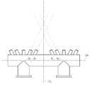
도 1은 본 발명의 실시 예에 따른 증착장치 및 기판을 개략적으로 나타낸 정면도이고, 도 2는 본 발명의 실시 예에 따른 증착장치 및 기판을 개략적으로 나타낸 사시도이며, 도 3은 본 발명의 실시 예에 따른 증착장치를 개략적으로 나타낸 정면도이다.FIG. 1 is a front view schematically showing a deposition apparatus and a substrate according to an embodiment of the present invention, FIG. 2 is a perspective view schematically showing a deposition apparatus and a substrate according to an embodiment of the present invention, FIG. 3 is a cross- Fig. 2 is a front view schematically showing a deposition apparatus according to a first embodiment of the present invention.
먼저, 도 1 내지 도 3을 참조하여 설명하자면, 본 발명의 실시 예에 따른 증착장치는 도가니부(미도시), 튜브부, 증착노즐부(100) 및 히터부를 포함하여 이루어 질 수 있다. 여기서 튜브부는 하나의 단일한 관과 같은 튜브형태도 가능하나, 전이튜브와 분배튜브를 포함하는 형태 또한 충분히 가능하다.1 to 3, a deposition apparatus according to an embodiment of the present invention may include a crucible (not shown), a tube portion, a
도가니부는 기판에 증착시킬 증착물질이 내재되며, 증착물질의 증발(vaporizing)이 이루어진다. 도가니부에 내재된 증착물질이 증발될 수 있도록 후술할 히터부의 도가니히터(미도시)가 도가니부를 가열시켜준다.The crucible part contains a deposition material to be deposited on the substrate, and evaporation of the deposition material is performed. A crucible heater (not shown) of the heater portion to be described later heats the crucible portion so that the evaporation material contained in the crucible portion can be evaporated.
그리고, 후술할 튜브부가 전이튜브와 분배튜를 포함하는 형태인 경우, 도가니부는 다수개의 독립적인 도가니(미도시)로 구성될 수 있다. 여기서, 각각의 도가니는 독립적으로 튜브부의 전이튜브(310)를 통해 튜브부의 분배튜브(210)와 연통된 형태도 바람직하다. 물론 도가니부가 하나의 도가니로 구성된 실시 형태 또한 가능하다.In the case where the tube portion to be described later includes a transition tube and a distribution tube, the furnace portion may be constituted by a plurality of independent crucibles (not shown). Here, it is also preferable that each crucible independently communicates with the
튜브부는 도가니부와 증착노즐부 사이에 연통되는 공간을 형성한다. 그리고 도가니부에서 증발된 증착물질이 증착노즐부에 도달하기까지 외부의 환경에 대하여 엄폐시켜준다.The tube portion forms a space communicating between the crucible portion and the deposition nozzle portion. And evaporation material vaporized in the crucible covers the outside environment until reaching the deposition nozzle part.
이러한 튜브부는 하나의 단일한 관이나 상자와 같은 형태 또는 도 1 및 도 2에서 참조되는 바와 같이 전이튜브(310)와 분배튜브를 포함하여 이루어진 형태 등이 가능하다.Such tubing may be in the form of a single tube or box, or may comprise a
전이튜브(transtion tube)(310)는 도가니부의 상측에 위치하여 도가니부와 연통된다. 그리고 도가니부로부터 증발된 증착물질이 전이튜브(310)로 유입된다.The
도가니부가 다수개의 도가니를 포함하여 이루어진 경우 다수개의 도가니 각각에 대응되도록 다수개의 전이튜브(310)로 구성된 것 또한 바람직하다.When the crucible includes a plurality of crucibles, it is also preferable that the crucible is composed of a plurality of
이러한 경우 다수개의 전이튜브(310) 각각은, 각기 대응되는 도가니와 분배튜브(210)가 연통될 수 있도록 분배튜브(210) 및 도가니와 연통된 것이 바람직하다.In this case, it is preferable that each of the plurality of
예를 들어, 도 1에서 두 개의 전이튜브(310)로 구성된 형태가 도시되어 있는데, 각각의 전이튜브(310)의 하측에 도가니가 연통되도록 연결되어 있으며, 각각의 도가니로부터 증착물질이 증발되면서 전이튜브(310)로 유입된다. 전이튜브(310)는 유입된 증착물질이 분배튜브(210)로 유입되도록 가이드한다.For example, FIG. 1 shows a configuration of two
분배튜브(Distribution tube)는 전이튜브(310)의 상측에 위치하며, 전이튜브(310)와 연통된다. 이러한 분배튜브는 도 1 내지 도 3에 도시된 바와 같이 하나의 분배튜브(210)로 이루어질 수도 있으며, 다수개의 분배튜브들(211, 212. 도 4 내지 도6 참조)로 이루어질 수도 있다.The distribution tube is located on the upper side of the
먼저, 도 1 내지 도 3을 참조하여 분배튜브가 하나의 분배튜브(210)로 이루어진 것을 기준으로 설명하고, 분배튜브가 다수개의 분배튜브들(211,212)로 구성된 경우는 후술하기로 한다.First, referring to FIGS. 1 to 3, a description will be made on the basis that the distribution tube is composed of one
도 1 내지 도 3에 도시된 바와 같이 분배튜브(210)는 일측에서 타측으로 길게 형성되고, 도가니부로부터 증발된 증착물질을 전이튜브(310)측으로부터 유입받는다.As shown in FIGS. 1 to 3, the
그리고, 분배튜브(210)의 상측에는 다수개의 증착노즐(111)들이 형성되어 있다. 여기서 다수개의 증착노즐(111)들은 하나 또는 다수의 증착노즐조(110)를 구성한다. 그리고 증착노즐부(100)는 하나 또는 다수의 증착노즐조(110)들로 구성된다.A plurality of
이와 같이 분배튜브(210)의 상측에 다수개의 증착노즐(111)들이 형성되어 있으며, 분배튜브(210)로 유입된 증착물질은 분배튜브(210) 내에서 다수개의 증착노즐(111)들을 통해 기판(S)측으로 증발되어 갈 수 있도록 고르게 분배된다.A plurality of
하나의 증착노즐조(110)에 포함되는 다수개의 증착노즐들은 튜브부의 상측에서 길이방향에 따라 일측에서 타측으로 열을 이루도록 배열되어 있는 것이 바람직하다.It is preferable that the plurality of deposition nozzles included in one
튜브부가 도 1 내지 도 2에 도시된 바와 같이 분배튜브(210)와 전이튜브(310)를 포함하는 경우, 다수개의 증착노즐들(111)은 분배튜브(210)의 길이방향에 따라 일측에서 타측으로 하나의 열을 이루도록 배열된 것이 바람직하다.When the tube part includes the
증착노즐부는 도가니부와 기판 사이에 마련되며, 증착물질이 기판 측을 향하여 증발되어 날아가는 방향을 설정하여 주는 다수의 증착노즐들을 포함하는 증착노즐조들로 구성된다.The deposition nozzle unit is formed between the crucible portion and the substrate, and is composed of deposition nozzle assemblies including a plurality of deposition nozzles that set the direction in which the deposition material evaporates toward the substrate side.
그리고, 증착노즐조(110)는 제1틸트(tilt)영역(120) 및 제2틸트영역(130)을 포함하여 이루어지며, 필요에 따라서는 직립영역(140)을 더 포함하여 이루어질 수도 있다.The deposition nozzle set 110 may include a
여기서 제1틸트영역(120)은, 튜브부의 일측방향 또는 원통형처럼 길게 형성된 분배튜브(210)에서 일측방향으로 소정의 각도(

조금 달리 표현하자면, 분배튜브(210)에서 일측방향으로 소정의 각도(

여기서

그리고, 제1틸트영역(120)에 속하는 다수의 증착노즐(111)들이 지향하는 방향이 일측방향으로서 틸트된 각도 가 모두 동일할 수도 있으며, 지향하는 방향이 일측 방향이지만, 구체적으로 틸트된 각도는 서로 조금씩 다르도록 형성될 수도 있다.The direction in which the plurality of
그리고, 제2틸트영역(130)은, 튜브부의 일측방향 또는 분배튜브(210)에서 타측방향으로 소정의 각도(

조금 달리 말하자면, 분배튜브(210)에서 타측으로 소정의 각도(

또한, 제2틸트영역(130)에 속하는 다수의 증착노즐(111)들이 지향하는 방향이 타측방향으로서 틸트된 각도 가 모두 동일할 수도 있으며, 지향하는 방향이 타측 방향이지만, 구체적으로 틸트된 각도는 서로 조금씩 다르도록 형성될 수도 있다.The direction in which the plurality of
이와 같은 제1틸트영역(120) 및 제2틸트영역(130)이 증착노즐조(110)에 포함된다. 그리고, 기판(S) 면의 중앙을 수직으로 지나가는 가상의 중심선(CL)에 대하여 대칭을 이루도록 (다시 말해서, 가상의 중심선(CL)을 기준으로 하여 대칭적 배치형태가 되도록) 다수개의 증착노즐조(110)가 배치된 것이 바람직하다.The
이와 같이 가상의 중심선(CL)을 기준으로 하여 다수개의 증착노즐조(110)가 대칭적배치형태가 된 예를 도 3에 개략적으로 도시하였다.An example in which a plurality of
여기서, 증착노즐조(110)는 앞서 잠깐 언급한 바와 같이 직립영역(140)을 더 포함하여 이루어질 수도 있다. 직립영역(140)은 제1틸트영역(120) 및 제2틸트영역(130) 사이에 위치하며, 기판(S)측을 향해 직립된 적어도 하나 이상의 증착노즐(111)들로 구성된다. 다시 말해서 분배튜브(210) 상에서 기판(S)측을 향하여 직립된 하나 또는 다수개의 증착노즐(111)들이 형성되어 있는 영역을 지칭한다고 할 수도 있다.Here, the deposition nozzle set 110 may further include the
그리고, 도 3에 도시된 바와 같이, 가상의 중심선(CL)을 사이에 두고 서로 이웃하는 두 개의 증착노즐조(110)에 있어서, 하나의 증착노즐조(110)의 제2틸트영역(130)에 속하는 증착노즐(111)이 지향하는 방향과 이웃하는 증착노즐조(110)의 제1틸트영역(120)에 속하는 증착노즐(111)이 지향하는 방향이 가상의 중심선에 대하여 대칭적으로 교차하도록 배치된 것 또한 바람직하다.3, in the two
여기서, 증착노즐(111)이 틸트된 각도(


히터부는 증착물질이 도가니부로부터 증발되어 기판(S) 측으로 공급될 수 있도록 도가니부, 튜브부 및 증착노즐부 중에서 적어도 어느 하나 이상을 가열하며, 바람직하게는 히터부에 의해 도가니부, 튜브부 및 증착노즐부(100)가 가열된다.The heater portion heats at least one of the crucible portion, the tube portion, and the deposition nozzle portion so that the evaporation material evaporates from the crucible portion and can be supplied to the substrate S side. Preferably, the heater portion conveys the crucible portion, The
이러한 히터부는 증착물질이 증발될 수 있도록 도가니부를 가열시키는 도가니히터(미도시), 튜브부의 전이튜브(310)를 가열시키는 전이히터(430), 튜브부의 분배튜브(210)를 가열시키는 분배히터(420), 증착노즐부(100)를 가열시키는 노즐히터(410)를 포함하여 이루어진 것이 바람직하다.The heater portion includes a crucible heater (not shown) for heating the crucible portion so that the evaporation material can be evaporated, a
참고로, 도 1 및 도 4에서는 전이튜브(310), 분배튜브(210) 및 증착노즐(111)을 쉽게 알아볼 수 있도록 도시하기 위하여 전이히터(430), 분배히터(420) 및 노즐히터(410)를 위치영역 정도 알 수 있게 개략적으로 도시하였다.1 and 4, a
여기서, 도가니히터는 다수개이고, 다수개의 도가니히터 각각은 다수개의 도가니 각각에 대응되어 배치되며, 다수개의 도가니 각각은, 각각의 도가니에서 증발되는 증착물질의 증발율을 제어하기가 좀더 용이하도록, 각기 대응되는 도가니히터에 의해 독립적으로 가열되는 것이 바람직하다.Here, a plurality of crucible heaters are arranged, and each of the plurality of crucible heaters is arranged corresponding to each of the plurality of crucibles, and each of the plurality of crucibles is provided with a plurality of crucible heaters, each of which corresponds to each evaporator so as to more easily control the evaporation rate of the evaporation material evaporated in each crucible It is preferable that the heating is performed independently by the crucible heater.
노즐히터(410)는 증착노즐의 온도가 도가니보다 고온이 될 수 있도록 증착노즐(111)을 가열시킬 수 있는 것이 바람직하다. 또는 증착노즐(111)이 일정한 온도를 유지하도록 가열시킬 수 있는 것 또한 바람직하다. 증착노즐(111)이 고온으로 가열되면 증발된 증착물질이 증착노즐(111)에 증착되어 붙을 가능성이 억제되므로 바람직하다.The
분배히터(420)는 분배튜브(210)의 온도가 도가니보다 고온이 되도록 분배튜브(210)를 가열시킬 수 있는 것이 바람직하며, 분배튜브(210)가 일정한 온도를 유지하도록 가열시킬 수 있는 것 또한 바람직하다. 분배튜브(210)가 도가니의 온도보다 높으면 분배튜브(210) 내에서 증착물질이 증착노즐(111)로 균등하게 분배될 수 있기 때문이다.The dispensing
한편, 분배튜브가 도 4 내지 도 6에 도시된 바와 같이 다수개인 경우에 대하여 설명하기로 한다. 이러한 경우에서는 튜브부에 포함되는 분배튜브가 다수개 라는 것이 앞서 설명한 것과 다소 차이가 있을 뿐 그 외는 대동소이하다.On the other hand, the case where there are a plurality of distribution tubes as shown in FIG. 4 to FIG. 6 will be described. In this case, the number of the distribution tubes included in the tube portion is somewhat different from that described above, but the other is very small.
도 4 내지 도 6에서 참조되는 바와 같이 튜브부에 다수개의 분배튜브(211, 212)가 포함되는 실시 형태에서, 도가니부는 다수개의 도가니를 포함하는 것이 바람직하다. 그리고, 분배튜브는 서로에 대해 독립되어 다수 마련되고, 전이튜브(310)는 다수개의 도가니 각각에 대응되도록 다수개의 전이튜브(311,312)로 구성된다. 그리고, 다수개의 전이튜브(311, 312) 각각은, 각기 대응되는 도가니와 분배튜브(211, 212)가 연통될 수 있도록 분배튜브(211, 212) 및 도가니와 연통된 것 또한 바람직하다.In embodiments where a plurality of
이처럼 분배튜브(211, 212)가 다수개인 경우에도 가상의 중심선(CL)을 기준으로 하여 대칭적으로 배치된 것이 바람직하다. 즉,가상의 중심선(CL)을 사이에 두고 서로 이웃하는 두 개의분배튜브(211, 212)의 증착노즐조에 있어서, 하나의 분배튜브(211)의 증착노즐조에 포함되는 제2틸트영역(130)에 속하는 증착노즐(111)이 지향하는 방향과 이웃하는 분배튜브(212)의 증착노즐조(110)의 제1틸트영역(120)에 속하는 증착노즐(111)이 지향하는 방향이 가상의 중심선(CL)에 대하여 대칭적으로 교차하도록 배치된 것 또한 바람직하다.Even if there are a plurality of
여기서 필요에 따라서는 도 4 내지 도 6에 도시된 바와 같이 증착노즐조에 직립영역이 없고 제1틸트영역(120)과 제2틸트영역(130)만이 있는 형태 또한 충분히 가능하며, 앞서 설명한 예에서와 같이 직립영역(140, 도 3참조)이 마련된 형태 또한 충분히 가능하다.As shown in FIGS. 4 to 6, if necessary, it is also possible to form the
그리고, 증착노즐(111)이 틸트된 각도(


여기서, 앞서 도 3에서 설명한 바와 같이


이상에서 설명한 바와 같이 본 발명에 따른 증착장치는 대면화된 기판에 대응하여 그 크기가 커질 필요없이 대면화된 기판면에 대하여 고르게 증착물질을 증발시켜줄 수 있으므로 증착물질을 균일한 증착두께로 증착시킬 수 있다. 따라서, 제품불량 발생율을 억제시킬 수 있으며, 증착장치의 크기가 커지지 않으므로 에너지소비 또한 증대되지 않는 등 제조비용 또한 절감시킬 수 있는 장점이 있다.As described above, the deposition apparatus according to the present invention can evaporate the deposition material evenly on the surface of the substrate, which does not need to be large in size corresponding to the large-sized substrate, so that the deposition material can be deposited at a uniform deposition thickness . Therefore, the occurrence rate of product defects can be suppressed, and since the size of the deposition apparatus is not increased, the energy consumption is not increased, and the manufacturing cost is also reduced.
이상에서 설명된 바와 같이, 본 발명에 대한 구체적인 설명은 첨부된 도면을 참조한 실시 예들에 의해서 이루어졌지만, 상술한 실시 예들은 본 발명의 바람직한 실시 예를 들어 설명하였을 뿐이기 때문에, 본 발명이 상기의 실시 예에만 국한되는 것으로 이해되어져서는 아니되며, 본 발명의 권리범위는 후술하는 청구범위 및 그 등가개념으로 이해되어져야 할 것이다.While the present invention has been described in connection with what is presently considered to be practical exemplary embodiments, it is to be understood that the invention is not limited to the disclosed embodiments, but, on the contrary, It is to be understood that the scope of the present invention is to be construed as being limited only by the embodiments, and the scope of the present invention should be understood as the following claims and their equivalents.
100 : 증착노즐부 110 : 증착노즐조
111 : 증착노즐 120 : 제1틸트영역
130 : 제2틸트영역 140 : 직립영역
210, 211, 212 : 분배튜브
310, 311, 312 : 전이튜브
410 : 노즐히터 420 : 분배히터
430 : 전이히터 CL : 가상의 중심선
DA : 분배튜브의 중심축 S : 기판100: deposition nozzle unit 110: deposition nozzle assembly
111: deposition nozzle 120: first tilt region
130: second tilt area 140: upright area
210, 211, 212: distribution tubes
310, 311, 312: Transition tube
410: Nozzle heater 420: Dispensing heater
430: transition heater CL: imaginary center line
DA: central axis of the distribution tube S: substrate
Claims (13)
Translated fromKorean상기 도가니부와 상기 기판 사이에 마련되며, 상기 증착물질이 상기 기판 측을 향하여 증발되어 날아가는 방향을 설정하여 주는 다수의 증착노즐들을 포함하는 증착노즐조들로 구성된 증착노즐부;
상기 도가니부와 상기 증착노즐부 사이에 연통되는 공간을 형성하며, 상기 도가니부에서 증발된 상기 증착물질이 상기 증착노즐부에 도달하기까지 외부의 환경에 대하여 엄폐시켜주는 튜브부; 및
상기 증착물질이 증발되어 상기 기판측으로 공급될 수 있도록 상기 도가니부, 상기 튜브부 및 상기 증착노즐부 중에서 적어도 어느 하나 이상을 가열하는 히터부;를 포함하며,
하나의 상기 증착노즐조에 포함되는 다수개의 증착노즐들은 상기 튜브부의 길이방향에 따라 일측에서 타측으로 하나의 열을 이루도록 배열되어 있고,
상기 증착노즐조는,
상기 튜브부의 일측방향으로 소정의 각도만큼 상향틸트된 적어도 하나 이상의 증착노즐들로 구성된 제1틸트영역 및
상기 튜브부의 타측방향으로 소정의 각도만큼 상향틸트된 적어도 하나 이상의 증착노즐들로 구성된 제2틸트영역을 포함하며,
상기 기판 면의 중앙을 수직으로 지나는 가상의 중심선에 대하여 대칭을 이루도록 다수개의 상기 증착노즐조가 배치된 것을 특징으로 하는 증착장치.
A crucible part in which a deposition material to be deposited is embedded in a substrate, and evaporation of the deposition material is performed;
And a plurality of deposition nozzles disposed between the crucible portion and the substrate and configured to set a direction in which the deposition material is evaporated toward the substrate side and set in a flying direction;
A tube portion forming a space communicating between the crucible portion and the deposition nozzle portion and covering the outside environment until the evaporation material evaporated in the crucible portion reaches the deposition nozzle portion; And
And a heater unit for heating at least one of the crucible portion, the tube portion, and the deposition nozzle portion so that the evaporation material can be evaporated and supplied to the substrate side,
The plurality of deposition nozzles included in one deposition nozzle group are arranged to form one row from one side to the other side along the longitudinal direction of the tube portion,
The deposition nozzle group
A first tilt region constituted by at least one or more evaporation nozzles upwardly tilted by a predetermined angle in one direction of the tube portion,
And a second tilt region composed of at least one or more evaporation nozzles upwardly tilted by a predetermined angle in the other direction of the tube portion,
Wherein a plurality of the deposition nozzle tiers are arranged symmetrically with respect to an imaginary center line passing vertically through the center of the substrate surface.
상기 증착노즐조는
상기 제1틸트영역 및 상기 제2틸트영역 사이에 위치하며, 상기 기판측으로 직립된 적어도 하나 이상의 증착노즐들로 구성된 직립영역을 더 포함하는 것을 특징으로 하는 증착장치.
The method according to claim 1,
The deposition nozzle set
Further comprising an upright region located between the first tilt region and the second tilt region and comprising at least one or more deposition nozzles standing upright to the substrate side.
상기 튜브부는,
상기 도가니부의 상측에 위치하여 상기 도가니부와 연통되며, 상기 도가니부로부터 증발된 상기 증착물질이 유입되는 전이튜브(transtion tube); 및
상기 전이튜브의 상측에 위치하여 상기 전이튜브와 연통되며, 일측에서 타측으로 길게 형성되고, 상기 도가니부로부터 증발된 상기 증착물질을 상기 전이튜브 측으로부터 유입받는 분배튜브(Distribution tube);를 포함하고,
상기 제1틸트영역은,
상기 분배튜브의 일측방향으로 소정의 각도만큼 상향 틸트된 적어도 하나 이상의 증착노즐들로 구성되고,
상기 제2틸트영역은,
상기 분배튜브의 타측방향으로 소정의 각도만큼 상향 틸트된 적어도 하나 이상의 증착노즐들로 구성된 것을 특징으로 하는 증착장치.
The method according to claim 1,
The tube portion includes:
A transtion tube disposed above the crucible portion and communicating with the crucible portion, the deposition material being evaporated from the crucible portion; And
And a distribution tube communicating with the transition tube located on the upper side of the transition tube and elongated from one side to the other side and flowing the evaporation material evaporated from the crucible part from the transition tube side, ,
Wherein the first tilt area includes:
And at least one or more evaporation nozzles upwardly tilted by a predetermined angle in one direction of the distribution tube,
Wherein the second tilt area comprises:
And at least one or more evaporation nozzles upwardly tilted by a predetermined angle in the other direction of the distribution tube.
상기 도가니부는,
다수개의 독립적인 도가니로 구성되되, 각각의 도가니는 독립적으로 상기 전이튜브를 통해 상기 분배튜브와 연통된 것을 특징으로 하는 증착장치.
The method of claim 3,
In the crucible portion,
Wherein each of the crucibles is independently communicated with the distribution tube through the transition tube.
상기 도가니부는 다수개의 도가니를 포함하며,
상기 전이튜브는 다수개의 상기 도가니 각각에 대응되도록 다수 마련되고,
다수개의 상기 전이튜브 각각은, 각기 대응되는 상기 도가니와 상기 분배튜브가 연통될 수 있도록 상기 분배튜브 및 상기 도가니와 연통된 것을 특징으로 하는 증착장치.
The method of claim 3,
The crucible portion includes a plurality of crucibles,
A plurality of transition tubes are provided to correspond to each of the plurality of crucibles,
Wherein each of the plurality of transition tubes is in communication with the distribution tube and the crucible so that the corresponding crucible and the distribution tube can communicate with each other.
상기 도가니부는 다수개의 도가니를 포함하며,
상기 분배튜브는 서로에 대해 독립되어 다수 마련되고,
상기 전이튜브는 다수개의 상기 도가니 각각에 대응되도록 다수 마련되고,
다수개의 상기 전이튜브 각각은, 각기 대응되는 상기 도가니와 상기 분배튜브가 연통될 수 있도록 상기 분배튜브 및 상기 도가니와 연통된 것을 특징으로 하는 증착장치.
The method of claim 3,
The crucible portion includes a plurality of crucibles,
The distribution tubes are provided in a plurality independent of one another,
A plurality of transition tubes are provided to correspond to each of the plurality of crucibles,
Wherein each of the plurality of transition tubes is in communication with the distribution tube and the crucible so that the corresponding crucible and the distribution tube can communicate with each other.
상기 가상의 중심선을 사이에 두고 서로 이웃하는 두 개의 상기 증착노즐조에 있어서,
하나의 상기 증착노즐조의 상기 제2틸트영역에 속하는 상기 증착노즐이 지향하는 방향과
이웃하는 상기 증착노즐조의 상기 제1틸트영역에 속하는 상기 증착노즐이 지향하는 방향이 상기 가상의 중심선에 대하여 대칭적으로 교차하도록 배치된 것을 특징으로 하는 증착장치.
The method of claim 3,
In the two deposition nozzle groups adjacent to each other with the imaginary center line therebetween,
The direction in which the deposition nozzle belonging to the second tilt region of one of the deposition nozzle tanks is directed
Wherein a direction in which the deposition nozzles belonging to the first tilt region of the adjacent deposition nozzle group are oriented symmetrically with respect to the imaginary center line.
상기 히터부는,
상기 도가니부를 가열시키는 도가니히터;
상기 전이튜브를 가열시키는 전이히터;
상기 분배튜브를 가열시키는 분배히터; 및
상기 증착노즐부를 가열시키는 노즐히터;를 포함하는 것을 특징으로 하는 증착장치.
The method of claim 3,
The heater unit includes:
A crucible heater for heating the crucible portion;
A transition heater for heating the transition tube;
A distribution heater for heating the distribution tube; And
And a nozzle heater for heating the deposition nozzle unit.
상기 도가니히터는 다수개이고,
다수개의 상기 도가니히터 각각은 다수개의 상기 도가니 각각에 대응되어 배치되며,
다수개의 도가니 각각은, 각기 대응되는 상기 도가니히터에 의해 독립적으로 가열되는 것을 특징으로 하는 증착장치
9. The method of claim 8,
There are a number of crucible heaters,
Each of the plurality of crucible heaters is disposed corresponding to each of the plurality of crucibles,
Characterized in that each of the plurality of crucibles is independently heated by the corresponding crucible heater
상기 노즐히터는,
상기 증착노즐의 온도가 상기 도가니보다 고온이 되도록 상기 증착노즐을 가열시킬 수 있는 것을 특징으로 하는 증착장치.
9. The method of claim 8,
The nozzle heater includes:
And the deposition nozzle can be heated so that the temperature of the deposition nozzle becomes higher than the temperature of the crucible.
상기 노즐히터는,
상기 증착노즐이 일정한 온도를 유지하도록 가열시킬 수 있는 것을 특징으로 하는 증착장치.
9. The method of claim 8,
The nozzle heater includes:
Wherein the deposition nozzle is heated to maintain a constant temperature.
상기 분배히터는,
상기 분배튜브의 온도가 상기 도가니보다 고온이 되도록 상기 분배튜브를 가열시킬 수 있는 것을 특징으로 하는 증착장치.
9. The method of claim 8,
The distribution heater includes:
Wherein the distribution tube is heated so that the temperature of the distribution tube is higher than the temperature of the crucible.
상기 분배히터는, 상기 분배튜브가 일정한 온도를 유지하도록 가열시킬 수 있는 것을 특징으로 하는 증착장치.
9. The method of claim 8,
Wherein the distribution heater is capable of heating the distribution tube to maintain a constant temperature.
Priority Applications (1)
| Application Number | Priority Date | Filing Date | Title |
|---|---|---|---|
| KR1020150180274AKR20170071984A (en) | 2015-12-16 | 2015-12-16 | Depositing Apparatus |
Applications Claiming Priority (1)
| Application Number | Priority Date | Filing Date | Title |
|---|---|---|---|
| KR1020150180274AKR20170071984A (en) | 2015-12-16 | 2015-12-16 | Depositing Apparatus |
Publications (1)
| Publication Number | Publication Date |
|---|---|
| KR20170071984Atrue KR20170071984A (en) | 2017-06-26 |
Family
ID=59282509
Family Applications (1)
| Application Number | Title | Priority Date | Filing Date |
|---|---|---|---|
| KR1020150180274ACeasedKR20170071984A (en) | 2015-12-16 | 2015-12-16 | Depositing Apparatus |
Country Status (1)
| Country | Link |
|---|---|
| KR (1) | KR20170071984A (en) |
Cited By (2)
| Publication number | Priority date | Publication date | Assignee | Title |
|---|---|---|---|---|
| KR20190080044A (en)* | 2017-12-28 | 2019-07-08 | 주식회사 선익시스템 | Crucible for linear evaporation source and Linear evaporation source having the same |
| KR20190129368A (en)* | 2018-05-10 | 2019-11-20 | 임우빈 | Multi-nozzle evaporating apparatus for deposition process |
- 2015
- 2015-12-16KRKR1020150180274Apatent/KR20170071984A/ennot_activeCeased
Cited By (2)
| Publication number | Priority date | Publication date | Assignee | Title |
|---|---|---|---|---|
| KR20190080044A (en)* | 2017-12-28 | 2019-07-08 | 주식회사 선익시스템 | Crucible for linear evaporation source and Linear evaporation source having the same |
| KR20190129368A (en)* | 2018-05-10 | 2019-11-20 | 임우빈 | Multi-nozzle evaporating apparatus for deposition process |
Similar Documents
| Publication | Publication Date | Title |
|---|---|---|
| JP4831841B2 (en) | Vacuum deposition apparatus and method | |
| JP4782219B2 (en) | Vacuum deposition equipment | |
| CN103215559B (en) | Apparatus and method for depositing thin film | |
| TWI690611B (en) | Vacuum deposition chamber | |
| TWI625876B (en) | Linear distribution pipe, a material deposition arrangement and a vacuum deposition apparatus using the same, and a method therefor | |
| JP2018532876A (en) | Nozzle for material deposition source configuration dispensing assembly, material deposition source configuration, vacuum deposition system, and method for depositing material | |
| KR20160112293A (en) | Evaporation source and Deposition apparatus including the same | |
| KR20160005877A (en) | Thin Film Deposition Apparatus with Multiple Evaporation Source | |
| US20130323868A1 (en) | Deposition Apparatus and Method for Manufacturing Organic Light Emitting Diode Display Using the Same | |
| JP2010261099A (en) | Deposition source | |
| JP5798171B2 (en) | Evaporating apparatus and method for mass production | |
| KR20170071984A (en) | Depositing Apparatus | |
| CN107002232A (en) | Crucible component for evaporating purpose | |
| KR20160005875A (en) | Thin Film Deposition Apparatus with Evaporation Source Installed Multi-Crucible | |
| KR101895801B1 (en) | Deposition Chamber including Spreading Guider | |
| KR20150012806A (en) | Apparatus of deposition | |
| KR20140055721A (en) | Evaporation source and apparatus for deposition having the same | |
| KR20150017849A (en) | Top-down evaporation source | |
| KR101893972B1 (en) | Deposition Chamber | |
| JP2020521039A (en) | Evaporation source for depositing evaporated material, vacuum deposition system, and method for depositing evaporated material | |
| KR102144790B1 (en) | Linear deposition unit and deposition apparutus coprising the same | |
| KR102155110B1 (en) | Linear Deposition Apparatus and Equipment Thereof | |
| JP3735287B2 (en) | Vacuum deposition apparatus and vacuum deposition method | |
| KR20160005876A (en) | Thin Film Deposition Apparatus with Multiple Evaporation Source | |
| KR102188345B1 (en) | Vapor deposition device substrate treting method |
Legal Events
| Date | Code | Title | Description |
|---|---|---|---|
| A201 | Request for examination | ||
| PA0109 | Patent application | Patent event code:PA01091R01D Comment text:Patent Application Patent event date:20151216 | |
| PA0201 | Request for examination | ||
| E902 | Notification of reason for refusal | ||
| PE0902 | Notice of grounds for rejection | Comment text:Notification of reason for refusal Patent event date:20161020 Patent event code:PE09021S01D | |
| AMND | Amendment | ||
| E601 | Decision to refuse application | ||
| PE0601 | Decision on rejection of patent | Patent event date:20170620 Comment text:Decision to Refuse Application Patent event code:PE06012S01D Patent event date:20161020 Comment text:Notification of reason for refusal Patent event code:PE06011S01I | |
| PG1501 | Laying open of application | ||
| AMND | Amendment | ||
| PX0901 | Re-examination | Patent event code:PX09011S01I Patent event date:20170620 Comment text:Decision to Refuse Application Patent event code:PX09012R01I Patent event date:20170217 Comment text:Amendment to Specification, etc. | |
| PX0601 | Decision of rejection after re-examination | Comment text:Decision to Refuse Application Patent event code:PX06014S01D Patent event date:20171016 Comment text:Amendment to Specification, etc. Patent event code:PX06012R01I Patent event date:20170821 Comment text:Decision to Refuse Application Patent event code:PX06011S01I Patent event date:20170620 Comment text:Amendment to Specification, etc. Patent event code:PX06012R01I Patent event date:20170217 Comment text:Notification of reason for refusal Patent event code:PX06013S01I Patent event date:20161020 |