KR20170071120A - Lkas system, vehicle including the same, and controlling method for lkas - Google Patents
Lkas system, vehicle including the same, and controlling method for lkasDownload PDFInfo
- Publication number
- KR20170071120A KR20170071120AKR1020150179088AKR20150179088AKR20170071120AKR 20170071120 AKR20170071120 AKR 20170071120AKR 1020150179088 AKR1020150179088 AKR 1020150179088AKR 20150179088 AKR20150179088 AKR 20150179088AKR 20170071120 AKR20170071120 AKR 20170071120A
- Authority
- KR
- South Korea
- Prior art keywords
- vehicle
- distance
- torque
- proximity
- initial torque
- Prior art date
- Legal status (The legal status is an assumption and is not a legal conclusion. Google has not performed a legal analysis and makes no representation as to the accuracy of the status listed.)
- Ceased
Links
Images


Classifications
- G—PHYSICS
- G06—COMPUTING OR CALCULATING; COUNTING
- G06V—IMAGE OR VIDEO RECOGNITION OR UNDERSTANDING
- G06V20/00—Scenes; Scene-specific elements
- G06V20/50—Context or environment of the image
- G06V20/56—Context or environment of the image exterior to a vehicle by using sensors mounted on the vehicle
- G06V20/588—Recognition of the road, e.g. of lane markings; Recognition of the vehicle driving pattern in relation to the road
- B—PERFORMING OPERATIONS; TRANSPORTING
- B62—LAND VEHICLES FOR TRAVELLING OTHERWISE THAN ON RAILS
- B62D—MOTOR VEHICLES; TRAILERS
- B62D15/00—Steering not otherwise provided for
- B62D15/02—Steering position indicators ; Steering position determination; Steering aids
- B62D15/025—Active steering aids, e.g. helping the driver by actively influencing the steering system after environment evaluation
- B—PERFORMING OPERATIONS; TRANSPORTING
- B60—VEHICLES IN GENERAL
- B60R—VEHICLES, VEHICLE FITTINGS, OR VEHICLE PARTS, NOT OTHERWISE PROVIDED FOR
- B60R1/00—Optical viewing arrangements; Real-time viewing arrangements for drivers or passengers using optical image capturing systems, e.g. cameras or video systems specially adapted for use in or on vehicles
- B—PERFORMING OPERATIONS; TRANSPORTING
- B60—VEHICLES IN GENERAL
- B60W—CONJOINT CONTROL OF VEHICLE SUB-UNITS OF DIFFERENT TYPE OR DIFFERENT FUNCTION; CONTROL SYSTEMS SPECIALLY ADAPTED FOR HYBRID VEHICLES; ROAD VEHICLE DRIVE CONTROL SYSTEMS FOR PURPOSES NOT RELATED TO THE CONTROL OF A PARTICULAR SUB-UNIT
- B60W10/00—Conjoint control of vehicle sub-units of different type or different function
- B60W10/20—Conjoint control of vehicle sub-units of different type or different function including control of steering systems
- B—PERFORMING OPERATIONS; TRANSPORTING
- B60—VEHICLES IN GENERAL
- B60W—CONJOINT CONTROL OF VEHICLE SUB-UNITS OF DIFFERENT TYPE OR DIFFERENT FUNCTION; CONTROL SYSTEMS SPECIALLY ADAPTED FOR HYBRID VEHICLES; ROAD VEHICLE DRIVE CONTROL SYSTEMS FOR PURPOSES NOT RELATED TO THE CONTROL OF A PARTICULAR SUB-UNIT
- B60W30/00—Purposes of road vehicle drive control systems not related to the control of a particular sub-unit, e.g. of systems using conjoint control of vehicle sub-units
- B60W30/02—Control of vehicle driving stability
- B60W30/025—Control of vehicle driving stability related to comfort of drivers or passengers
- B—PERFORMING OPERATIONS; TRANSPORTING
- B60—VEHICLES IN GENERAL
- B60W—CONJOINT CONTROL OF VEHICLE SUB-UNITS OF DIFFERENT TYPE OR DIFFERENT FUNCTION; CONTROL SYSTEMS SPECIALLY ADAPTED FOR HYBRID VEHICLES; ROAD VEHICLE DRIVE CONTROL SYSTEMS FOR PURPOSES NOT RELATED TO THE CONTROL OF A PARTICULAR SUB-UNIT
- B60W30/00—Purposes of road vehicle drive control systems not related to the control of a particular sub-unit, e.g. of systems using conjoint control of vehicle sub-units
- B60W30/10—Path keeping
- B60W30/12—Lane keeping
- B—PERFORMING OPERATIONS; TRANSPORTING
- B60—VEHICLES IN GENERAL
- B60W—CONJOINT CONTROL OF VEHICLE SUB-UNITS OF DIFFERENT TYPE OR DIFFERENT FUNCTION; CONTROL SYSTEMS SPECIALLY ADAPTED FOR HYBRID VEHICLES; ROAD VEHICLE DRIVE CONTROL SYSTEMS FOR PURPOSES NOT RELATED TO THE CONTROL OF A PARTICULAR SUB-UNIT
- B60W40/00—Estimation or calculation of non-directly measurable driving parameters for road vehicle drive control systems not related to the control of a particular sub unit, e.g. by using mathematical models
- B60W40/08—Estimation or calculation of non-directly measurable driving parameters for road vehicle drive control systems not related to the control of a particular sub unit, e.g. by using mathematical models related to drivers or passengers
- B—PERFORMING OPERATIONS; TRANSPORTING
- B60—VEHICLES IN GENERAL
- B60W—CONJOINT CONTROL OF VEHICLE SUB-UNITS OF DIFFERENT TYPE OR DIFFERENT FUNCTION; CONTROL SYSTEMS SPECIALLY ADAPTED FOR HYBRID VEHICLES; ROAD VEHICLE DRIVE CONTROL SYSTEMS FOR PURPOSES NOT RELATED TO THE CONTROL OF A PARTICULAR SUB-UNIT
- B60W40/00—Estimation or calculation of non-directly measurable driving parameters for road vehicle drive control systems not related to the control of a particular sub unit, e.g. by using mathematical models
- B60W40/10—Estimation or calculation of non-directly measurable driving parameters for road vehicle drive control systems not related to the control of a particular sub unit, e.g. by using mathematical models related to vehicle motion
- B—PERFORMING OPERATIONS; TRANSPORTING
- B62—LAND VEHICLES FOR TRAVELLING OTHERWISE THAN ON RAILS
- B62D—MOTOR VEHICLES; TRAILERS
- B62D6/00—Arrangements for automatically controlling steering depending on driving conditions sensed and responded to, e.g. control circuits
- G—PHYSICS
- G06—COMPUTING OR CALCULATING; COUNTING
- G06V—IMAGE OR VIDEO RECOGNITION OR UNDERSTANDING
- G06V20/00—Scenes; Scene-specific elements
- G06V20/50—Context or environment of the image
- G06V20/56—Context or environment of the image exterior to a vehicle by using sensors mounted on the vehicle
- B—PERFORMING OPERATIONS; TRANSPORTING
- B60—VEHICLES IN GENERAL
- B60R—VEHICLES, VEHICLE FITTINGS, OR VEHICLE PARTS, NOT OTHERWISE PROVIDED FOR
- B60R2300/00—Details of viewing arrangements using cameras and displays, specially adapted for use in a vehicle
- B60R2300/80—Details of viewing arrangements using cameras and displays, specially adapted for use in a vehicle characterised by the intended use of the viewing arrangement
- B60R2300/804—Details of viewing arrangements using cameras and displays, specially adapted for use in a vehicle characterised by the intended use of the viewing arrangement for lane monitoring
- B—PERFORMING OPERATIONS; TRANSPORTING
- B60—VEHICLES IN GENERAL
- B60W—CONJOINT CONTROL OF VEHICLE SUB-UNITS OF DIFFERENT TYPE OR DIFFERENT FUNCTION; CONTROL SYSTEMS SPECIALLY ADAPTED FOR HYBRID VEHICLES; ROAD VEHICLE DRIVE CONTROL SYSTEMS FOR PURPOSES NOT RELATED TO THE CONTROL OF A PARTICULAR SUB-UNIT
- B60W40/00—Estimation or calculation of non-directly measurable driving parameters for road vehicle drive control systems not related to the control of a particular sub unit, e.g. by using mathematical models
- B60W40/08—Estimation or calculation of non-directly measurable driving parameters for road vehicle drive control systems not related to the control of a particular sub unit, e.g. by using mathematical models related to drivers or passengers
- B60W2040/0818—Inactivity or incapacity of driver
- B—PERFORMING OPERATIONS; TRANSPORTING
- B60—VEHICLES IN GENERAL
- B60W—CONJOINT CONTROL OF VEHICLE SUB-UNITS OF DIFFERENT TYPE OR DIFFERENT FUNCTION; CONTROL SYSTEMS SPECIALLY ADAPTED FOR HYBRID VEHICLES; ROAD VEHICLE DRIVE CONTROL SYSTEMS FOR PURPOSES NOT RELATED TO THE CONTROL OF A PARTICULAR SUB-UNIT
- B60W2420/00—Indexing codes relating to the type of sensors based on the principle of their operation
- B60W2420/40—Photo, light or radio wave sensitive means, e.g. infrared sensors
- B60W2420/403—Image sensing, e.g. optical camera
- B—PERFORMING OPERATIONS; TRANSPORTING
- B60—VEHICLES IN GENERAL
- B60W—CONJOINT CONTROL OF VEHICLE SUB-UNITS OF DIFFERENT TYPE OR DIFFERENT FUNCTION; CONTROL SYSTEMS SPECIALLY ADAPTED FOR HYBRID VEHICLES; ROAD VEHICLE DRIVE CONTROL SYSTEMS FOR PURPOSES NOT RELATED TO THE CONTROL OF A PARTICULAR SUB-UNIT
- B60W2554/00—Input parameters relating to objects
- B60W2554/80—Spatial relation or speed relative to objects
- B60W2554/801—Lateral distance
- B—PERFORMING OPERATIONS; TRANSPORTING
- B60—VEHICLES IN GENERAL
- B60W—CONJOINT CONTROL OF VEHICLE SUB-UNITS OF DIFFERENT TYPE OR DIFFERENT FUNCTION; CONTROL SYSTEMS SPECIALLY ADAPTED FOR HYBRID VEHICLES; ROAD VEHICLE DRIVE CONTROL SYSTEMS FOR PURPOSES NOT RELATED TO THE CONTROL OF A PARTICULAR SUB-UNIT
- B60W2710/00—Output or target parameters relating to a particular sub-units
- B60W2710/06—Combustion engines, Gas turbines
- B60W2710/0666—Engine torque
- B—PERFORMING OPERATIONS; TRANSPORTING
- B60—VEHICLES IN GENERAL
- B60W—CONJOINT CONTROL OF VEHICLE SUB-UNITS OF DIFFERENT TYPE OR DIFFERENT FUNCTION; CONTROL SYSTEMS SPECIALLY ADAPTED FOR HYBRID VEHICLES; ROAD VEHICLE DRIVE CONTROL SYSTEMS FOR PURPOSES NOT RELATED TO THE CONTROL OF A PARTICULAR SUB-UNIT
- B60W2710/00—Output or target parameters relating to a particular sub-units
- B60W2710/08—Electric propulsion units
- B60W2710/083—Torque
- B—PERFORMING OPERATIONS; TRANSPORTING
- B60—VEHICLES IN GENERAL
- B60W—CONJOINT CONTROL OF VEHICLE SUB-UNITS OF DIFFERENT TYPE OR DIFFERENT FUNCTION; CONTROL SYSTEMS SPECIALLY ADAPTED FOR HYBRID VEHICLES; ROAD VEHICLE DRIVE CONTROL SYSTEMS FOR PURPOSES NOT RELATED TO THE CONTROL OF A PARTICULAR SUB-UNIT
- B60W2710/00—Output or target parameters relating to a particular sub-units
- B60W2710/20—Steering systems
- B60W2710/202—Steering torque
- B—PERFORMING OPERATIONS; TRANSPORTING
- B60—VEHICLES IN GENERAL
- B60Y—INDEXING SCHEME RELATING TO ASPECTS CROSS-CUTTING VEHICLE TECHNOLOGY
- B60Y2300/00—Purposes or special features of road vehicle drive control systems
- B60Y2300/10—Path keeping
- B60Y2300/12—Lane keeping
Landscapes
- Engineering & Computer Science (AREA)
- Mechanical Engineering (AREA)
- Transportation (AREA)
- Automation & Control Theory (AREA)
- Multimedia (AREA)
- Physics & Mathematics (AREA)
- Combustion & Propulsion (AREA)
- Chemical & Material Sciences (AREA)
- General Physics & Mathematics (AREA)
- Theoretical Computer Science (AREA)
- Control Of Driving Devices And Active Controlling Of Vehicle (AREA)
- Mathematical Physics (AREA)
- Traffic Control Systems (AREA)
- Steering Control In Accordance With Driving Conditions (AREA)
Abstract
Translated fromKoreanDescription
Translated fromKorean본 발명은 LKAS 시스템, 이를 포함하는 차량, 및 LKAS 제어 방법에 관한 것으로, 더욱 상세하게는 운전자의 부주의를 감지하여 안전운전을 지원하는 시스템의 사용자 만족도를 향상시키기 위한 LKAS 시스템, 이를 포함하는 차량, 및 LKAS 제어 방법에 관한 것이다.BACKGROUND OF THE
현재는 도로를 주행하는 차량에 대한 자세 제어와 주행 안정성의 향상을 위한 장치들이 지속적으로 개발되고 있다.Currently, devices for improving the posture control and the driving stability of the vehicle running on the road are being continuously developed.
일례로, 단순 제동 시 한계를 극복하면서 차량의 안정성을 향상하도록 제동 시 제동 액압을 제어하는 ABS(Antilock brake system)이나, 차량의 급 발진이나 급 가속시 과대한 슬립을 방지하기 위해 엔진의 구동력을 조절하는 TCS(Traction control system)나, 또는 운전자가 요구하는 차량주행방향과 실제 차량의 주행방향과의 차이를 최소화시켜 어떠한 운전조건에서도 안전하게 운전자가 의도한 차량의 주행방향을 유지시켜 주는 ESP(Electronic Stability Program)등은 실제 차량에 적용되고 있는 기술들이다.For example, an ABS (Antilock Brake System) that controls the braking fluid pressure during braking to improve the stability of the vehicle while overcoming the limitations in simple braking, and an anti-slip brake system (TCS) which controls the driving direction of the vehicle, or the difference between the driving direction required by the driver and the actual driving direction of the vehicle is minimized, so that the ESP Stability Program) are technologies applied to real vehicles.
이에 더해 운전자의 부주의를 감지하여 안전운전을 지원하는 보조장치로서, 차량이 주행차선으로부터 이탈되는 현상을 방지하는 차선 유지 지원장치(LKAS, Lane Keeping Assist/Support System)가 개발되어 상용화되고 있는 추세이다. 이러한 LKAS는 운전자의 조향 부담 경감 및 주행차선 이탈에 따른 대형사고를 미연에 방지하기 위해서, 주행차선 이탈이 발생될 것으로 판단되는 상황에서는, 조향 액츄에이터를 이용하여 조향 장치에 토크를 가해 주행차선의 중앙으로 차량을 복귀시켜 주는 기술이다.In addition, a lane keeping assistance / support system (LKAS) for preventing a driver from being separated from a driving lane has been developed and commercialized as an auxiliary device for detecting a driver's carelessness and supporting safe driving . In the LKAS, in order to reduce the steering burden on the driver and prevent a large accident caused by the departure of the driving lane, in the case where it is determined that the lane departure will occur, the steering actuator is used to apply torque to the steering device, To return the vehicle to.
예를 들어 LKAS의 제어는 이미지로 제공되는 차선 정보에 따라 차량의 진행 방향에 대한 각종 정보와, 이론적으로 가상한 조향과 차량 모델에 근거한 각종 정보를 계산한 후, 이들 값을 피드백(Feedback)시켜 주행중인 실 차량에 대한 제어를 수행하는 방식을 이용한다.For example, the control of the LKAS calculates various kinds of information about the traveling direction of the vehicle, various theoretical information based on the steering and the vehicle model according to the lane information provided in the image, and then feedbacks these values And a method of performing control on a real vehicle being driven is used.
그러나, 이와 같은 LKAS의 제어 구현은 주행 차량의 인접 차선에서 주행중인 차량에 대한 고려가 전혀 되지 않은 상태에서 토크 제어를 실행하므로, 근접 차선에서 가까이 운행중인 차량이 있을 때 자차 운전자는 순간적인 위험을 느끼게 되어, LKAS 제어에 대한 거부감이 생길 수 있다. 또한, 이러한 거부감은 차량 자체의 체감 품질을 저하시킬 우려가 있어, 이에 대한 개선이 요구되고 있다.However, such a control implementation of the LKAS carries out the torque control without consideration of the vehicle being driven in the adjacent lane of the driving vehicle. Therefore, when there is a vehicle running close to the lane, So that there is a sense of resistance to the LKAS control. In addition, such a feeling of rejection is likely to deteriorate the quality of the sensation of the vehicle itself, and improvement thereof is required.
본 발명은 토크 제어시 운전자에게 거부감이 생기지 않도록 근접 차량의 위치를 고려하여 토크 제어를 실행하는 LKAS 시스템, 이를 포함하는 차량, 및 LKAS 제어 방법을 제공하기 위한 것이다.The present invention is to provide an LKAS system that performs torque control in consideration of the position of a nearby vehicle so that the driver does not have a sense of resistance in torque control, a vehicle including the LKAS system, and an LKAS control method.
본 발명에서 이루고자 하는 기술적 과제들은 이상에서 언급한 기술적 과제들로 제한되지 않으며, 언급하지 않은 또 다른 기술적 과제들은 아래의 기재로부터 본 발명이 속하는 기술분야에서 통상의 지식을 가진 자에게 명확하게 이해될 수 있을 것이다.It is to be understood that both the foregoing general description and the following detailed description are exemplary and explanatory and are not restrictive of the invention, unless further departing from the spirit and scope of the invention as defined by the appended claims. It will be possible.
상기와 같은 기술적 과제를 해결하기 위하여, 본 발명의 일 실시 예에 따른 차량이 주행차선으로부터 이탈되는 현상을 방지하는 LKAS(Lane Keeping Assist/Support System) 시스템은, AVM(Around View Monitoring) 시스템의 주변 촬영 영상을 분석하여 근접 차량이 존재하는지 판단하는 LKAS 제어부; 상기 차량의 위치를 산출하는 자차 위치 계산부; 상기 근접 차량이 존재할 경우, 상기 근접 차량의 위치를 산출하는 근접 차량 위치 계산부; 상기 차량의 위치 및 상기 근접 차량의 위치를 기초로 생성된 근접 지수가 임계치 이하인지 판단하고, 상기 근접 지수가 상기 임계치 이하인 경우, 상기 차량의 위치에 기초한 초기 토크 시점 및 초기 토크량을 보정하는 토크 제어부; 및 상기 보정된 초기 토크 시점 및 상기 보정된 초기 토크량에 따라, 차량의 조향을 제어하는 조향 장치를 포함할 수 있다.According to an aspect of the present invention, there is provided an LKAS (Lane Keeping Assist / Support System) system for preventing a vehicle from being separated from a driving lane according to an embodiment of the present invention. An LKAS controller for analyzing the photographed image to determine whether an adjacent vehicle exists; A sub-vehicle position calculation unit for calculating the position of the vehicle; A proximity vehicle position calculation unit for calculating a position of the proximity vehicle when the proximity vehicle exists; A torque estimating means for estimating a torque that corrects an initial torque point and an initial torque amount based on the position of the vehicle when the proximity index generated based on the position of the vehicle and the position of the proximal vehicle is below a threshold value, A control unit; And a steering device for controlling steering of the vehicle in accordance with the corrected initial torque point and the corrected initial torque amount.
본 발명의 일 실시 예에 따른 차량이 주행차선으로부터 이탈되는 현상을 방지하는 LKAS(Lane Keeping Assist/Support System) 제어 방법은, AVM(Around View Monitoring) 시스템의 주변 촬영 영상을 분석하여 근접 차량이 존재하는지 판단하는 단계; 상기 근접 차량이 존재할 경우, 상기 차량의 위치 및 상기 근접 차량의 위치를 산출하는 단계; 상기 차량의 위치 및 상기 근접 차량의 위치를 기초로 생성된 근접 지수가 임계치 이하인지 판단하는 단계; 상기 근접 지수가 상기 임계치 이하인 경우, 상기 차량의 위치에 기초한 초기 토크 시점 및 초기 토크량을 보정하는 단계; 및 상기 보정된 초기 토크 시점 및 상기 보정된 초기 토크량에 따라, 차량의 조향을 제어하는 단계를 포함할 수 있다.A Lane Keeping Assist / Support System (LKAS) control method for preventing a vehicle from being detached from a driving lane according to an embodiment of the present invention analyzes surrounding photographs of an AVM (Around View Monitoring) system, ; Calculating a position of the vehicle and a position of the nearby vehicle when the proximity vehicle exists; Determining whether the proximity index generated based on the position of the vehicle and the position of the proximal vehicle is below a threshold value; Correcting an initial torque point and an initial torque amount based on the position of the vehicle when the proximity index is below the threshold; And controlling the steering of the vehicle according to the corrected initial torque point and the corrected initial torque amount.
상기와 같이 구성되는 본 발명의 일 실시 예에 따른 LKAS 시스템, 이를 포함하는 차량, 및 LKAS 제어 방법에 의하면, 주행 차량의 주변에 근접 차량이 존재할 경우 근접 차량의 존재 여부 및 근접 차량과의 거리에 따라, 토크 제어 시점 및 토크 제어량을 가변시킴으로써 차량의 운전자가 LKAS 제어에 대한 거부감을 느끼지 않도록 하여 차량의 체감 품질을 향상 시킬 수 있다.According to the LKAS system, the vehicle including the LKAS system, and the LKAS control method according to an embodiment of the present invention, when there is a nearby vehicle in the vicinity of the traveling vehicle, Accordingly, by varying the torque control point and the torque control amount, it is possible to prevent the driver of the vehicle from feeling the resistance to the LKAS control, thereby improving the feeling of quality of the vehicle.
본 발명에서 얻을 수 있는 효과는 이상에서 언급한 효과들로 제한되지 않으며, 언급하지 않은 또 다른 효과들은 아래의 기재로부터 본 발명이 속하는 기술분야에서 통상의 지식을 가진 자에게 명확하게 이해될 수 있을 것이다.The effects obtained by the present invention are not limited to the above-mentioned effects, and other effects not mentioned can be clearly understood by those skilled in the art from the following description will be.
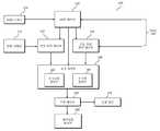
도 1은 본 발명의 일 실시예에 따른 차량을 개략적으로 도시한 블록도이다.
도 2는 도 1에 도시된 LKAS 시스템을 보다 상세히 나타낸 블록도이다.
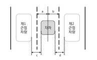
도 3은 도 2에 도시된 토크 제어부가 계산하는 근접 지수에 대한 개념을 설명하기 위한 도면이다.
도 4는 본 발명의 일 실시예에 따른 LKAS 제어 방법을 도시한 흐름도이다.1 is a block diagram schematically illustrating a vehicle according to an embodiment of the present invention.
FIG. 2 is a block diagram showing the LKAS system shown in FIG. 1 in more detail.
FIG. 3 is a diagram for explaining a concept of a proximity index calculated by the torque control unit shown in FIG. 2. FIG.
4 is a flowchart illustrating a LKAS control method according to an embodiment of the present invention.
이하, 본 발명과 관련된 적어도 하나의 실시 예에 대하여 도면을 참조하여 보다 상세하게 설명한다. 이하의 설명에서 사용되는 구성요소에 대한 접미사 "모듈" 및 "부"는 명세서 작성의 용이함만이 고려되어 부여되거나 혼용되는 것으로서, 그 자체로 서로 구별되는 의미 또는 역할을 갖는 것은 아니다.Hereinafter, at least one embodiment related to the present invention will be described in detail with reference to the drawings. The suffix "module" and " part "for the components used in the following description are given or mixed in consideration of ease of specification, and do not have their own meaning or role.
도 1은 본 발명의 일 실시예에 따른 차량을 개략적으로 도시한 블록도이다.1 is a block diagram schematically illustrating a vehicle according to an embodiment of the present invention.
도 1을 참조하면, 차량(10)은 LKAS(Lane Keeping Assist/Support System) 시스템(100)과 AVM(Around View Monitoring) 시스템(200)을 포함할 수 있다.Referring to FIG. 1, the
LKAS 시스템(100)은 운전자의 부주의를 감지하여 안전운전을 지원하는 보조장치의 일종으로서, 차량(10)이 주행차선으로부터 이탈되는 현상을 방지하기 위해, 주행차선으로부터 이탈이 발생될 것으로 판단되는 상황에서는, 조향 장치에 토크를 가해 주행차선의 중앙으로 차량을 복귀시킬 수 있다.The LKAS
LKAS 시스템(100)은 차량(10)의 전방에 설치된 카메라로 촬영되는 이미지에 기초하여 주행차선으로부터의 이탈을 감지하게 되는데, 이와는 별도로 인접 차선에서 주행중인 차량의 위치를 감지하여 조향 장치에 대한 토크 제어에 이용할 수 있다.The LKAS
LKAS 시스템(100)은 상기 인접 차선에서 주행중인 차량에 대한 정보를 AVM 시스템(200)으로부터 획득할 수 있다.The LKAS
AVM 시스템(200)은 차량(10)의 운행시 AVM 기능을 제공하는데, 상기 AVM 기능은 차량(10)의 주차시 또는 출발시에 차량(10)의 주변을 촬영하고 촬영된 영상을 이용하여, 마치 차량(10)을 위에서 내려다보다 보는 것과 같은 화면을 제공하는 기능을 말한다.The
AVM 시스템(200)은 LKAS 시스템(100)의 요청에 따라 차량(10)의 주차시 또는 출발시 이외의 시간에서도, 차량(10)의 주변을 촬영하고 촬영된 영상을 LKAS 시스템(100)에 제공할 수 있다.The
도 2는 도 1에 도시된 LKAS 시스템을 보다 상세히 나타낸 블록도이다. 도 3은 도 2에 도시된 토크 제어부가 계산하는 근접 지수에 대한 개념을 설명하기 위한 도면이다.FIG. 2 is a block diagram showing the LKAS system shown in FIG. 1 in more detail. FIG. 3 is a diagram for explaining a concept of a proximity index calculated by the torque control unit shown in FIG. 2. FIG.
도 2와 도 3을 참조하면, LKAS 시스템(100)은 LKAS 스위치(105), LKAS 제어부(110), 전방 카메라(115), 자차 위치 계산부(120), 근접 차량 위치 계산부(130), 토크 제어부(140), 조향 제어부(150), 제어상황 표시부(160), 및 조향 장치(170)를 포함할 수 있다.2 and 3, the LKAS
LKAS 스위치(105)는 사용자로부터 LKAS 기능을 활성화 또는 비활성화하기 위한 제어 신호를 수신하는 인터페이스(interface)로서, 차량 헤드 유닛(미도시)의 일부로 포함될 수 있다. LKAS 스위치(105)는 사용자로부터 LKAS 기능을 제어하는 신호를 입력받아 LKAS 제어부(110)로 전송할 수 있다. LKAS 스위치(105)는 별물형 스위치 혹은 클러스터 내의 USM(User Setting Menu) 스위치로 구현될 수 있다.The
LKAS 제어부(110)는 LKAS 시스템(100)의 전반적인 동작을 제어하며, LKAS 스위치(105)로부터 전송되는 LKAS 기능을 제어하는 신호에 의해 활성화 또는 비활성화될 수 있다.The LKAS
LKAS 제어부(110)가 활성화되면, LKAS 제어부(110)는 LKAS 시스템(100)을 일반 모드 또는 복합 모드로 동작시킬 수 있다. 이때, LKAS 제어부(110)는 AVM 시스템(200)에 주변 촬영 영상을 요청하며, 상기 주변 촬영 영상을 기초로 동작 모드를 결정할 수 있다.When the LKAS
상기 일반 모드는 전방 카메라(115)가 촬영한 영상만을 기초로 주행 차선에 대한 차량(10)의 위치를 계산하여 토크를 제어하는 모드이며, 상기 복합 모드는 전방 카메라(115)가 촬영한 영상 뿐 아니라 상기 주변 촬영 영상으로부터 획득되는 정보도 함께 고려하여 토크를 제어하는 모드를 의미한다.The general mode is a mode for controlling the torque by calculating the position of the
LKAS 제어부(110)는 상기 주변 촬영 영상 즉, AVM 시스템(200)의 전, 후, 좌, 우에 설치된 카메라 각각의 가시 거리 내로 촬영되는 영상을 분석하여, 근접 차량이 존재할 경우에는 상기 일반 모드로 진입하며, 근접 차량이 존재하지 않을 경우에는 상기 복합 모드로 진입할 수 있다.The LKAS
이하에서는, 상기 일반 모드에서의 LKAS 시스템(100)의 동작과 상기 복합 모드에서의 LKAS 시스템(100)의 동작을 순차적으로 설명하기로 한다.Hereinafter, the operation of the LKAS
첫째로, 상기 일반 모드에서, LKAS 제어부(110)는 자차 위치 계산부(120)를 활성화하고, 근접 차량 위치 계산부(130)를 비활성화할 수 있다.First, in the normal mode, the LKAS
자차 위치 계산부(120)는 전방 카메라(115)가 촬영한 전방 촬영 영상을 분석하여 현재 차량(10)이 주행하는 차선을 검출할 수 있다.The sub-vehicle
예를 들어, 자차 위치 계산부(120)는 상기 전방 촬영 영상에 대하여 잡음을 제거하고, 잡음이 제거된 영상신호에 대하여 다중 해상도 영상으로 만들어 분리하고, 분리된 다중해상도를 유지하면서 차선 엣지(edge)를 추출하는 방식으로 상기 전방 촬영 영상에서 차량(10)이 주행하는 차선을 검출할 수 있다.For example, the car
자차 위치 계산부(120)는 검출된 상기 차량(10)이 주행하는 차선과 차량(10)의 중심 간의 거리를 산출할 수 있다. 도 3에서, 자차 위치 계산부(120)는 자차의 양 옆에 위치하는 차선을 검출한 뒤, 자차의 중심과 왼쪽 차선 간의 거리인 제1 거리(a)와 자차의 중심과 오른쪽 차선 간의 거리인 제2 거리(b)를 각각 산출할 수 있다.The sub-vehicle
자차 위치 계산부(120)는 산출된 제1 거리(a)와 제2 거리(b)를 토크 제어부(140)로 전송할 수 있다.The sub-vehicle
토크 제어부(140)의 토크시점 결정부(142)와 토크량 결정부(144)는 제1 거리(a)와 제2 거리(b)를 기초로 차량(10)을 주행 차선의 중앙으로 위치시키도록 하는 토크시점과 토크량을 결정할 수 있다.The torque
상기 토크시점은 토크 제어를 시작하는 시점을 의미하며, 제1 거리(a)와 제2 거리(b) 간의 비율과 1의 차이(절대값)가 클수록 상기 토크시점이 앞당겨질 수 있고, 제1 거리(a)와 제2 거리(b) 간의 비율과 1의 차이가 작을수록 상기 토크시점이 늦춰질 수 있다. 즉, 제1 거리(a)와 제2 거리(b) 간의 비율과 1의 차이는 차량(10)이 좌측 또는 우측 차선과 얼마나 치우쳐 있는지에 대한 값이다.The torque time point means a time point at which the torque control is started. The larger the difference (absolute value) between the ratio between the first distance a and the second distance b and 1 is, the earlier the torque point can be advanced, The smaller the difference between the ratio between the distance a and the second distance b is, the slower the torque point may be. That is, the ratio between the first distance (a) and the second distance (b) and the difference of 1 are values as to how far the
또한, 상기 토크량은 토크 제어시 가해지는 토크의 정도를 의미하며, 제1 거리(a)와 제2 거리(b) 간의 비율과 1의 차이(절대값)가 클수록 상기 토크량이 커질 수 있고, 제1 거리(a)와 제2 거리(b) 간의 비율과 1의 차이가 작을수록 상기 토크량이 작아질 수 있다.The torque amount means the degree of torque applied during torque control. The larger the difference between the ratio of the first distance (a) and the second distance (b) and the difference (absolute value) of 1, The smaller the difference between the ratio between the first distance a and the second distance b is, the smaller the torque amount can be.
토크 제어부(140)가 결정한 토크시점과 토크량은 조향 제어부(150)로 전달되며, 조향 제어부(150)는 상기 토크시점과 상기 토크량에 따라, 조향 장치(170)를 제어하기 위한 신호를 출력한다. 또한, 조향 제어부(150)는 상기 신호를 제어상황 표시부(160)로도 출력할 수 있다.The torque start point and the torque amount determined by the
제어상황 표시부(160)는 차량(10)의 대시보드의 디스플레이, 스피커, 햅틱 등으로 구현될 수 있다. 예를 들어, 조향 제어부(150)에 의한 토크 제어 상황이 차량(10)의 대시보드의 디스플레이를 통해 표시될 수 있으며, 긴급한 토크 제어 상황 발생시 스피커로 경고음이 출력되거나, 햅틱 경보가 출력될 수 있다.The control
조향 장치(170)는 차량(10)의 조향을 보조하는 수단으로서, 전동식 조향장치(EPS: Electric Power Steering) 및 모터구동 조향장치(MDPS: Motor Driven Power Steering) 중 적어도 하나를 포함할 수 있다. 조향 장치(170)는 조향 제어부(150)의 제어에 따라, 차량(10)을 주행 차선의 중심에 위치시키도록 할 수 있다.The
둘째로, 상기 복합 모드에서, LKAS 제어부(110)는 자차 위치 계산부(120)와 근접 차량 위치 계산부(130)를 모두 활성화할 수 있다.Second, in the hybrid mode, the
자차 위치 계산부(120)는 상기 일반 모드에서 설명한 바와 같이 제1 거리(a)와 제2 거리(b)를 산출하여 토크 제어부(140)로 전달하며, 중복되는 상세한 설명은 생략하기로 한다.The sub-vehicle
근접 차량 위치 계산부(130)는 AVM 시스템(200)의 주변 촬영 영상으로부터 차량(10)의 주행 차선의 인접 차선에서 주행 중인 근접 차량과 차량(10) 간의 거리를 산출할 수 있다.The proximate vehicle
도 3에서, 자차를 중심으로 왼쪽의 인접 차선에 제1 근접 차량이 주행중이고 오른쪽의 인접 차선에 제2 근접 차량이 주행중인 경우, 근접 차량 위치 계산부(130)는 상기 주변 촬영 영상에 대하여 잡음을 제거하고, 잡음이 제거된 영상신호에 대하여 다중 해상도 영상으로 만들어 분리하고, 분리된 다중해상도를 유지하면서 제1 근접 차량과 제2 근접 차량의 좌표 및 자차의 좌표를 검출하여 자차와 제1 또는 제2 근접 차량 간의 수평 거리를 검출할 수 있다. 여기서, 검출되는 수평 거리는 자차와 제1 근접 차량 간의 수평 거리인 제3 거리(c)와 자차와 제2 근접 차량 간의 수평 거리인 제4 거리(d)를 포함할 수 있다.3, when the first nearest vehicle is traveling on the left lane adjacent to the vehicle and the second nearest vehicle is traveling on the right lane adjacent to the vehicle, the proximity vehicle
만일, 제1 근접 차량 또는 제2 근접 차량 중 어느 하나만이 존재할 경우에는 존재하는 차량에 대한 수평 거리만이 산출됨은 당연하다.If there is only one of the first proximity vehicle and the second proximity vehicle, it is natural that only the horizontal distance to the existing vehicle is calculated.
근접 차량 위치 계산부(130)는 산출된 제3 거리(c)와 제4 거리(d)를 토크 제어부(140)로 전달할 수 있다.The proximity vehicle
토크 제어부(140)는 제1 내지 제4 거리(a~d)를 기초로 제1 근접 지수와 제2 근접 지수를 생성하고, 상기 제1 근접 지수와 상기 제2 근접 지수가 각각 제1 임계치와 제2 임계치 이하인지 판단할 수 있다. 판단 결과, 상기 각 근접 지수가 상기 각 임계치 이하이고 소정의 조건을 만족할 경우, 토크 제어부(140)는 토크시점과 토크량을 보정할 수 있다. 반대로, 상기 각 근접 지수가 상기 각 임계치를 초과하고 소정의 조건을 만족할 경우, 토크 제어부(140)는 토크시점과 토크량을 보정하지 않고, 상기 일반 모드와 동일한 방식으로 토크시점과 토크량을 결정할 수 있다.The
구체적으로, 토크 제어부(140)는 제3 거리(c)로부터 제1 거리(a)를 감산하여 제1 근접 지수를 생성할 수 있다. 도 3에서, 제3 거리(c)로부터 제1 거리(a)를 감산한 결과는, 좌측 차선과 제1 근접 차량 간의 거리로부터 자차의 폭을 감산한 값과 같게 되는데 자차의 폭은 일정 상수이므로 제3 거리(c)로부터 제1 거리(a)를 감산한 결과는 좌측 차선과 제1 근접 차량 간의 거리에 따라 가변되는 값이 된다. 따라서, 상기 제1 근접 지수는 제1 근접 차량이 좌측 차선과 얼마나 근접하여 주행하는지에 대해 수치화된 값이다.Specifically, the
마찬가지로, 토크 제어부(140)는 제4 거리(d)로부터 제2 거리(b)를 감산하여 제2 근접 지수를 생성할 수 있다. 도 3에서, 제4 거리(d)로부터 제2 거리(b)를 감산한 결과는, 우측 차선과 제2 근접 차량 간의 거리로부터 자차의 폭을 감산한 값과 같게 되는데 자차의 폭은 일정 상수이므로 제4 거리(d)로부터 제2 거리(b)를 감산한 결과는 우측 차선과 제2 근접 차량 간의 거리에 따라 가변되는 값이 된다. 따라서, 상기 제2 근접 지수는 제2 근접 차량이 우측 차선과 얼마나 근접하여 주행하는지에 대해 수치화된 값이다.Similarly, the
토크 제어부(140)는 제1 근접 지수(c-a)가 제1 임계치(v) 이하인지 판단하고, 제2 근접 지수(d-b)가 제2 임계치(w) 이하인지 판단할 수 있다. 즉, 토크 제어부(140)는 제1 근접 차량과 제2 근접 차량이 미리 정해진 수준을 벗어날 정도로 좌우차선에 근접하여 주행하는지 여부를 판단할 수 있다.The
상기 제1 임계치(v)와 상기 제2 임계치(w)는 차량(10)의 폭, 차량(10)의 속도, 주행 차선의 폭, 사용자의 운전 성향 등이 고려되어 정해지는 수치일 수 있고, 서로 동일할 수 있으나 본 발명의 범위는 이에 한정되지 않는다.The first threshold value v and the second threshold value w may be numerical values determined by considering the width of the
한편, 토크시점 결정부(142)와 토크량 결정부(144)는 상기 일반 모드에서와 같이 제1 거리(a)와 제2 거리(b)를 기초로 토크시점과 토크량을 결정하게 되는데, 이렇게 결정된 토크시점과 토크량을 초기 토크시점(t1)과 초기 토크량(Ψ1)으로 정의하기로 한다.On the other hand, the torque-point-in-
여기서, 토크량은 차량(10)을 좌측 방향으로 토크 제어를 수행할지 또는 우측 방향으로 토크 제어를 수행할지 여부에 대한 토크 제어 방향에 대한 정보를 포함한다. 예컨대, 토크량의 부호가 +인 경우, 토크 제어 방향이 좌측 방향이고 토크량의 부호가 -인 경우, 토크 제어 방향이 우측 방향일 수 있다.Here, the amount of torque includes information on the torque control direction as to whether to perform the torque control to the left side of the
제1 근접 지수가 제1 임계치(v) 이하이고 제1 거리(a)와 제2 거리(b)를 기초로 정해진 토크 제어 방향이 좌측 방향인 경우, 토크 제어부(140)는 토크시점 결정부(142)와 토크량 결정부(144)가 각각 초기 토크시점(t1)과 초기 토크량(Ψ1)을 보정하도록 제어할 수 있다.When the first proximity index is equal to or less than the first threshold value v and the torque control direction determined based on the first distance a and the second distance b is the leftward direction, the
위의 경우 토크시점 결정부(142)는 상기 초기 토크시점을 시점 보정치(t') 만큼 앞당기거나 늦추는 시점 보정을 수행할 수 있다. 시점 보정치(t')는 제1 근접 지수에 반비례할 수 있으나, 본 발명의 범위는 이에 한정되지 않는다.In this case, the torque-point-in-
또한, 토크시점 결정부(142)는 근접 차량 위치 계산부(130)로부터 자차에 대한 제1 근접 차량의 상대 수직 거리를 수신하여, 이를 기초로 상기 초기 토크시점을 시점 보정치(t') 만큼 앞당기거나 늦추는 시점 보정을 수행할 수 있다. 상기 상대 수직 거리는 자차의 중심에 대한 Y좌표로부터 제1 근접 차량의 중심에 대한 Y좌표를 감산한 값으로, 양수일 경우 자차가 제1 근접 차량보다 앞서는 경우이며, 음수일 경우 자차가 제1 근접 차량보다 뒤처진 경우이다.In addition, the torque-point-in-
따라서, 자차가 제1 근접 차량보다 앞서는 경우에는 자차의 운행자에게 제1 근접 차량이 시야에 아직 보이지 않는 상태이므로 토크 제어를 보다 빠르게 가져갈 필요가 있다. 반대로, 자차가 제1 근접 차량보다 뒤처진 경우에는 자차의 운행자에게 제1 근접 차량이 시야에 현재 보이는 상태이므로 토크 제어를 보다 천천히 가져갈 필요가 있다.Therefore, when the vehicle is ahead of the first close-up vehicle, it is necessary to take the torque control more quickly since the first close-up vehicle is not yet visible to the driver of the vehicle. On the contrary, when the vehicle is behind the first proximity vehicle, the first proximity vehicle is presently visible to the driver of the vehicle, and therefore, it is necessary to take the torque control more slowly.
즉, 토크시점 결정부(142)는 자차에 대한 제1 근접 차량의 상대 수직 거리가 양수이면 상기 초기 토크시점을 시점 보정치(t') 만큼 앞당길 수 있으며, 토크시점 결정부(142)는 자차에 대한 제1 근접 차량의 상대 수직 거리가 음수이면 상기 초기 토크시점을 시점 보정치(t') 만큼 늦출 수 있다.That is, the torque-point-in-
아울러, 위의 경우 토크량 결정부(144)는 상기 초기 토크량을 토크량 보정치(Ψ') 만큼 높이거나 낮추는 토크량 보정을 수행할 수 있다. 토크량 보정치(Ψ')는 제1 근접 지수에 반비례할 수 있으나, 본 발명의 범위는 이에 한정되지 않는다.In addition, in the above case, the torque-
또한, 토크량 보정부(144)는 근접 차량 위치 계산부(130)로부터 자차에 대한 제1 근접 차량의 상대 수직 거리를 수신하여, 이를 기초로 상기 초기 토크량을 토크량 보정치(Ψ') 만큼 높이거나 낮추는 토크량 보정을 수행할 수 있다.Also, the torque
따라서, 자차가 제1 근접 차량보다 앞서는 경우에는 자차의 운행자에게 제1 근접 차량이 시야에 아직 보이지 않는 상태이므로 토크 제어량을 보다 크게 가져갈 필요가 있다. 반대로, 자차가 제1 근접 차량보다 뒤처진 경우에는 자차의 운행자에게 제1 근접 차량이 시야에 현재 보이는 상태이므로 토크 제어량을 보다 적게 가져갈 필요가 있다.Therefore, when the vehicle is ahead of the first close-up vehicle, the first close-up vehicle is still invisible to the driver of the vehicle, so it is necessary to increase the torque control amount. On the contrary, when the vehicle is behind the first proximity vehicle, it is necessary to reduce the torque control amount because the first proximity vehicle is presently visible to the driver of the vehicle.
즉, 토크량 결정부(144)는 자차에 대한 제1 근접 차량의 상대 수직 거리가 양수이면 상기 초기 토크량을 토크량 보정치(Ψ')만큼 높일 수 있으며, 토크량 결정부(144)는 자차에 대한 제1 근접 차량의 상대 수직 거리가 음수이면 상기 초기 토크량을 토크량 보정치(Ψ') 만큼 늦출 수 있다.That is, the torque
위의 경우와 마찬가지로, 제2 근접 지수가 제2 임계치(w) 이하이고 제1 거리(a)와 제2 거리(b)를 기초로 정해진 토크 제어 방향이 우측 방향인 경우, 토크 제어부(140)는 토크시점 결정부(142)와 토크량 결정부(144)가 각각 초기 토크시점(t1)과 초기 토크량(Ψ1)을 보정하도록 제어할 수 있다.When the second proximity index is equal to or less than the second threshold value w and the torque control direction determined based on the first distance a and the second distance b is the right direction, Can be controlled such that the torque-point-in-
여기서, 토크시점 결정부(142)와 토크량 결정부(144)가 각각 초기 토크시점(t1)과 초기 토크량(Ψ1)을 보정하는 방식은 위의 경우에서 설명된 바와 실질적으로 동일하므로 상세한 설명은 생략하기로 한다.The manner in which the torque-point-in-
정리하자면, 제1 근접 지수가 제1 임계치(v) 이하이고 제1 거리(a)와 제2 거리(b)를 기초로 정해진 토크 제어 방향이 좌측 방향인 경우(제1 케이스), 또는 제2 근접 지수가 제2 임계치(w) 이하이고 제1 거리(a)와 제2 거리(b)를 기초로 정해진 토크 제어 방향이 우측 방향인 경우(제2 케이스), 토크시점 결정부(142)와 토크량 결정부(144)는 각각 초기 토크시점(t1)과 초기 토크량(Ψ1)을 보정한 보정 토크 시점(t2=t1±t')과 보정 토크량(Ψ2=Ψ1± Ψ')을 조향 제어부(150)로 전달할 수 있다.If the first proximity index is equal to or less than the first threshold value v and the torque control direction determined based on the first distance a and the second distance b is the left direction (first case) When the proximity index is equal to or less than the second threshold value w and the torque control direction determined on the basis of the first distance a and the second distance b is the right direction (second case), the torque
상기 제1 케이스와 상기 제2 케이스를 제외한 경우에는, 보정 동작이 수행될 필요가 없으므로, 토크시점 결정부(142)와 토크량 결정부(144)는 각각 초기 토크시점(t1)과 초기 토크량(Ψ1)을 조향 제어부(150)로 전달할 수 있다.Since the correction operation need not be performed when the first case and the second case are excluded, the torque-point-in-
이하의 조향 제어부(150), 제어상황 표시부(160), 조향 장치(170)의 동작은 상기 일반 모드와 실질적으로 동일하므로 상세한 설명은 생략하기로 한다.The operation of the
본 발명의 일 실시예에 따른 LKAS 시스템(100)에 의하면, 차량(10)의 주변에 근접 차량이 존재할 경우 근접 차량과의 거리에 따라, 토크 제어 시점 및 토크 제어량을 가변시킴으로써 차량(10)의 운전자가 LKAS 제어에 대한 거부감을 느끼지 않도록 할 수 있다.According to the
도 4는 본 발명의 일 실시예에 따른 LKAS 제어 방법을 도시한 흐름도이다.4 is a flowchart illustrating a LKAS control method according to an embodiment of the present invention.
도 4를 참조하면, LKAS 스위치(105)를 통해 입력되는 LKAS 기능을 활성화하기 위한 제어 신호에 따라 LKAS 제어부(110)는 활성화되어 LKAS 제어를 시작할 수 있다(S10).Referring to FIG. 4, the
LKAS 제어부(110)는 AVM 시스템(200)으로부터 수신된 주변 촬영 영상을 기초로 주행 차선에 인접한 좌우 차선에 차량이 존재하는지 판단할 수 있다(S20).The
상기 좌우 차선에 차량이 존재하지 않는 경우(S20의 No), LKAS 제어부(110)는 LKAS 시스템(100)을 일반 모드로 동작시키며, 상기 일반 모드에 대한 설명은 도 2와 도3에서 설명된 바와 같다.When the vehicle does not exist in the left and right lanes (No in S20), the
상기 좌우 차선에 차량이 존재하는 경우(S20의 Yes), LKAS 제어부(110)는 LKAS 시스템(100)을 복합 모드로 동작시키며, LKAS 제어부(110)는 자차 위치 계산부(120)와 근접 차량 위치 계산부(130)를 모두 활성화시킬 수 있다.The
자차 위치 계산부(120)는 자차의 위치에 대한 정보인 제1 거리(a)와 제2 거리(b)를 산출하며, 근접 차량 위치 계산부(130)는 근접 차량(제1 근접 차량과 제2 근접 차량)의 위치에 대한 정보인 제3 거리(c)와 제4 거리(d)를 산출할 수 있다(S30).The sub-vehicle
토크 제어부(140)는 제1 내지 제4 거리(a~d)를 기초로 제1 근접 지수와 제2 근접 지수를 생성하고, 상기 제1 근접 지수와 상기 제2 근접 지수가 각각 제1 임계치와 제2 임계치 이하인지 판단할 수 있다. 판단 결과, 상기 각 근접 지수가 상기 각 임계치 이하일 경우, 토크 제어부(140)는 토크시점과 토크량을 보정할 수 있다. 반대로, 상기 각 근접 지수가 상기 각 임계치를 초과할 경우, 토크 제어부(140)는 토크시점과 토크량을 보정하지 않고, 상기 일반 모드와 동일한 방식으로 토크시점과 토크량을 결정할 수 있다.The
토크 제어부(140)는 제1 내지 제4 거리(a~d)를 기초로 제1 근접 지수와 제2 근접 지수를 생성하고, 상기 제1 근접 지수와 상기 제2 근접 지수가 각각 제1 임계치와 제2 임계치 이하인지 판단할 수 있다(S40).The
제1 근접 지수가 제1 임계치(v) 이하이고 제1 거리(a)와 제2 거리(b)를 기초로 정해진 토크 제어 방향이 좌측 방향인 경우, 및 제2 근접 지수가 제2 임계치(w) 이하이고 제1 거리(a)와 제2 거리(b)를 기초로 정해진 토크 제어 방향이 우측 방향인 경우를 제외한 경우(S40의 No), 토크시점 결정부(142)와 토크량 결정부(144)는 각각 상기 일반 모드에서와 같이 초기 토크시점(t1)과 초기 토크량(Ψ1)을 조향 제어부(150)로 전달할 수 있다.When the first proximity index is equal to or less than the first threshold value v and the torque control direction determined based on the first distance a and the second distance b is the left direction and when the second proximity index is equal to the second threshold value w ) And the torque control direction determined based on the first distance a and the second distance b is the right direction (No in S40), the torque-
제1 근접 지수가 제1 임계치(v) 이하이고 제1 거리(a)와 제2 거리(b)를 기초로 정해진 토크 제어 방향이 좌측 방향인 경우, 또는 제2 근접 지수가 제2 임계치(w) 이하이고 제1 거리(a)와 제2 거리(b)를 기초로 정해진 토크 제어 방향이 우측 방향인 경우(S40의 Yes), 토크시점 결정부(142)와 토크량 결정부(144)는 각각 초기 토크시점(t1)과 초기 토크량(Ψ1)을 보정한 보정 토크 시점(t2=t1±t')과 보정 토크량(Ψ2=Ψ1± Ψ')을 조향 제어부(150)로 전달할 수 있다(S50, S60).When the first proximity index is equal to or less than the first threshold value v and the torque control direction defined based on the first distance a and the second distance b is the left direction or when the second proximity index is equal to the second threshold value w ) And the determined torque control direction is the right direction based on the first distance a and the second distance b (Yes in S40), the torque-point-in-
상기와 같이 설명된 방법은 컴퓨터로 읽을 수 있는 기록 매체에 컴퓨터가 읽을 수 있는 코드로서 구현되는 것이 가능하다. 컴퓨터가 읽을 수 있는 기록매체로는 컴퓨터 시스템에 의하여 해독될 수 있는 데이터가 저장된 모든 종류의 기록 매체를 포함한다. 예를 들어, ROM(Read Only Memory), RAM(Random Access Memory), 자기 테이프, 자기 디스크, 플래쉬 메모리, 광 데이터 저장장치 등이 있을 수 있다. 또한, 컴퓨터가 읽을 수 있는 기록매체는 컴퓨터 통신망으로 연결된 컴퓨터 시스템에 분산되어, 분산방식으로 읽을 수 있는 코드로서 저장되고 실행될 수 있다.The method described above can be implemented as computer-readable code on a computer-readable recording medium. The computer-readable recording medium includes all kinds of recording media storing data that can be decoded by a computer system. For example, it may be a ROM (Read Only Memory), a RAM (Random Access Memory), a magnetic tape, a magnetic disk, a flash memory, an optical data storage device, or the like. In addition, the computer-readable recording medium may be distributed and executed in a computer system connected to a computer network, and may be stored and executed as a code readable in a distributed manner.
또한, 상기에서는 본 발명의 바람직한 실시예를 참조하여 설명하였지만, 해당 기술 분야에서 통상의 지식을 가진 자라면 하기의 특허 청구의 범위에 기재된 본 발명의 사상 및 영역으로부터 벗어나지 않는 범위 내에서 본 발명을 다양하게 수정 및 변경시킬 수 있음을 이해할 수 있을 것이다.It will be apparent to those skilled in the art that various modifications and variations can be made in the present invention without departing from the spirit or scope of the invention as defined in the appended claims. It will be understood that various modifications and changes may be made.
Claims (19)
Translated fromKoreanAVM(Around View Monitoring) 시스템의 주변 촬영 영상을 분석하여 근접 차량이 존재하는지 판단하는 LKAS 제어부;
상기 차량의 위치를 산출하는 자차 위치 계산부;
상기 근접 차량이 존재할 경우, 상기 근접 차량의 위치를 산출하는 근접 차량 위치 계산부;
상기 차량의 위치 및 상기 근접 차량의 위치를 기초로 생성된 근접 지수가 임계치 이하인지 판단하고, 상기 근접 지수가 상기 임계치 이하인 경우, 상기 차량의 위치에 기초한 초기 토크 시점 및 초기 토크량을 보정하는 토크 제어부; 및
상기 보정된 초기 토크 시점 및 상기 보정된 초기 토크량에 따라, 차량의 조향을 제어하는 조향 장치를 포함하는 LKAS 시스템.1. A Lane Keeping Assist / Support System (LKAS) system for preventing a vehicle from being separated from a driving lane,
An LKAS control unit for analyzing a surrounding photographed image of an AVM (Around View Monitoring) system to determine whether an adjacent vehicle exists;
A sub-vehicle position calculation unit for calculating the position of the vehicle;
A proximity vehicle position calculation unit for calculating a position of the proximity vehicle when the proximity vehicle exists;
A torque estimating means for estimating a torque that corrects an initial torque point and an initial torque amount based on the position of the vehicle when the proximity index generated based on the position of the vehicle and the position of the proximal vehicle is below a threshold value, A control unit; And
And a steering device for controlling the steering of the vehicle according to the corrected initial torque point and the corrected initial torque amount.
상기 자차 위치 계산부는, 전방 촬영 영상을 분석하여 상기 차량의 위치를 산출하는 LKAS 시스템.The method according to claim 1,
Wherein the car position calculating unit calculates the position of the vehicle by analyzing the front photographing image.
상기 근접 차량 위치 계산부는 상기 주변 촬영 영상을 분석하여 상기 근접 차량의 위치를 산출하는 LKAS 시스템.The method according to claim 1,
And the proximate vehicle position calculation unit calculates the position of the nearby vehicle by analyzing the surrounding photographing image.
상기 차량의 위치는 상기 차량의 중심과 좌측 차선 간의 거리인 제1 거리 및 상기 차량의 중심과 우측 차선간의 거리인 제2 거리를 포함하고,
상기 근접 차량의 위치는 상기 차량과 좌측 근접 차량의 수평 거리인 제3 거리 및 상기 차량과 우측 근접 차량의 수평 거리인 제4 거리 중 적어도 하나를 포함하는 LKAS 시스템.The method according to claim 1,
Wherein the position of the vehicle includes a first distance that is a distance between a center lane of the vehicle and a left lane and a second distance that is a distance between a center lane of the vehicle and a right lane,
Wherein the position of the proximity vehicle includes at least one of a third distance which is a horizontal distance between the vehicle and the left close-up vehicle and a fourth distance which is a horizontal distance between the vehicle and the right close-up vehicle.
상기 근접 지수는 제1 근접 지수와 제2 근접 지수를 포함하고,
상기 토크 제어부는,
상기 제3 거리로부터 상기 제1 거리를 감산하여 상기 제1 근접 지수를 생성하고, 상기 제4 거리로부터 상기 제2 거리를 감산하여 상기 제2 근접 지수를 생성하는 LKAS 시스템.5. The method of claim 4,
Wherein the proximity index includes a first proximity index and a second proximity index,
The torque control unit includes:
Subtracting the first distance from the third distance to generate the first proximity index, and subtracting the second distance from the fourth distance to generate the second proximity index.
상기 토크 제어부는,
상기 제1 근접 지수가 제1 임계치 이하인 경우, 상기 차량의 위치에 기초한 초기 토크 시점 및 초기 토크량을 상기 제1 근접 지수에 의해 결정되는 시점 보정치 및 토크량 보정치 만큼 보정하는 LKAS 시스템.6. The method of claim 5,
The torque control unit includes:
And corrects an initial torque point and an initial torque amount based on the vehicle position by a time point correction value and a torque amount correction value determined by the first proximity index, when the first proximity index is equal to or less than the first threshold value.
상기 토크 제어부는,
상기 주변 촬영 영상을 분석하여 생성되는 상대 수직 거리를 기초로, 상기 초기 토크 시점 및 상기 초기 토크량을 상기 시점 보정치 및 상기 토크량 보정치 만큼 증가 또는 감소시키는 LKAS 시스템.The method according to claim 6,
The torque control unit includes:
Wherein the initial torque point and the initial torque amount are increased or decreased by the time correction value and the torque amount correction value based on a relative vertical distance generated by analyzing the peripheral photographing image.
상기 토크 제어부는,
상기 제2 근접 지수가 제2 임계치 이하인 경우, 상기 차량의 위치에 기초한 초기 토크 시점 및 초기 토크량을 상기 제2 근접 지수에 의해 결정되는 시점 보정치 및 토크량 보정치 만큼 보정하는 LKAS 시스템.6. The method of claim 5,
The torque control unit includes:
And corrects an initial torque point and an initial torque amount based on the vehicle position by a point correction value and a torque correction value determined by the second proximity index when the second proximity index is equal to or less than a second threshold value.
상기 토크 제어부는,
상기 주변 촬영 영상을 분석하여 생성되는 상대 수직 거리를 기초로, 상기 초기 토크 시점 및 상기 초기 토크량을 상기 시점 보정치 및 상기 토크량 보정치 만큼 증가 또는 감소시키는 LKAS 시스템.The method according to claim 6,
The torque control unit includes:
Wherein the initial torque point and the initial torque amount are increased or decreased by the time correction value and the torque amount correction value based on a relative vertical distance generated by analyzing the peripheral photographing image.
상기 LKAS 시스템의 제어에 따라, 상기 주변 촬영 영상을 제공하는 AVM 시스템을 포함하는 차량.The LKAS system of claim 1; And
And an AVM system for providing the surrounding photographic image under the control of the LKAS system.
AVM(Around View Monitoring) 시스템의 주변 촬영 영상을 분석하여 근접 차량이 존재하는지 판단하는 단계;
상기 근접 차량이 존재할 경우, 상기 차량의 위치 및 상기 근접 차량의 위치를 산출하는 단계;
상기 차량의 위치 및 상기 근접 차량의 위치를 기초로 생성된 근접 지수가 임계치 이하인지 판단하는 단계;
상기 근접 지수가 상기 임계치 이하인 경우, 상기 차량의 위치에 기초한 초기 토크 시점 및 초기 토크량을 보정하는 단계; 및
상기 보정된 초기 토크 시점 및 상기 보정된 초기 토크량에 따라, 차량의 조향을 제어하는 단계를 포함하는 LKAS 제어 방법.A Lane Keeping Assist / Support System (LKAS) control method for preventing a vehicle from being separated from a driving lane,
Analyzing a surrounding photographed image of an AVM (Around View Monitoring) system to determine whether an adjacent vehicle exists;
Calculating a position of the vehicle and a position of the nearby vehicle when the proximity vehicle exists;
Determining whether the proximity index generated based on the position of the vehicle and the position of the proximal vehicle is below a threshold value;
Correcting an initial torque point and an initial torque amount based on the position of the vehicle when the proximity index is below the threshold; And
And controlling the steering of the vehicle according to the corrected initial torque point and the corrected initial torque amount.
상기 차량의 위치를 산출하는 단계는, 전방 촬영 영상을 분석하여 상기 차량의 위치를 산출하는 단계를 포함하는 LKAS 제어 방법.12. The method of claim 11,
Wherein calculating the position of the vehicle includes calculating a position of the vehicle by analyzing a front photographing image.
상기 근접 차량의 위치를 산출하는 단계는, 상기 주변 촬영 영상을 분석하여 상기 근접 차량의 위치를 산출하는 단계를 포함하는 LKAS 제어 방법.12. The method of claim 11,
Wherein the step of calculating the position of the nearby vehicle includes the step of calculating the position of the near vehicle by analyzing the surrounding photographing image.
상기 차량의 위치는 상기 차량의 중심과 좌측 차선 간의 거리인 제1 거리 및 상기 차량의 중심과 우측 차선간의 거리인 제2 거리를 포함하고,
상기 근접 차량의 위치는 상기 차량과 좌측 근접 차량의 수평 거리인 제3 거리 및 상기 차량과 우측 근접 차량의 수평 거리인 제4 거리 중 적어도 하나를 포함하는 LKAS 제어 방법.12. The method of claim 11,
Wherein the position of the vehicle includes a first distance that is a distance between a center lane of the vehicle and a left lane and a second distance that is a distance between a center lane of the vehicle and a right lane,
Wherein the position of the proximity vehicle includes at least one of a third distance that is the horizontal distance between the vehicle and the left proximate vehicle and a fourth distance that is a horizontal distance between the vehicle and the right proximity vehicle.
상기 근접 지수는 제1 근접 지수와 제2 근접 지수를 포함하고,
상기 근접 지수가 상기 임계치 이하인지 판단하는 단계는,
상기 제3 거리로부터 상기 제1 거리를 감산하여 상기 제1 근접 지수를 생성하고, 상기 제4 거리로부터 상기 제2 거리를 감산하여 상기 제2 근접 지수를 생성하는 단계를 포함하는 LKAS 제어 방법.15. The method of claim 14,
Wherein the proximity index includes a first proximity index and a second proximity index,
Determining whether the proximity index is less than or equal to the threshold,
Generating the first proximity index by subtracting the first distance from the third distance and subtracting the second distance from the fourth distance to generate the second proximity index.
상기 초기 토크 시점 및 상기 초기 토크량을 보정하는 단계는,
상기 제1 근접 지수가 제1 임계치 이하인 경우, 상기 차량의 위치에 기초한 초기 토크 시점 및 초기 토크량을 상기 제1 근접 지수에 의해 결정되는 시점 보정치 및 토크량 보정치 만큼 보정하는 단계를 포함하는 LKAS 제어 방법.16. The method of claim 15,
The step of correcting the initial torque point and the initial torque amount includes:
And correcting an initial torque point and an initial torque amount based on the position of the vehicle by a point correction value and a torque correction value determined by the first proximity index when the first proximity index is less than or equal to a first threshold value, Way.
상기 초기 토크 시점 및 상기 초기 토크량은 상기 주변 촬영 영상을 분석하여 생성되는 상대 수직 거리를 기초로, 상기 시점 보정치 및 상기 토크량 보정치 만큼 증가 또는 감소되는 LKAS 제어 방법.17. The method of claim 16,
Wherein the initial torque time and the initial torque amount are increased or decreased by the time correction value and the torque amount correction value based on a relative vertical distance generated by analyzing the surrounding photographing image.
상기 초기 토크 시점 및 상기 초기 토크량을 보정하는 단계는,
상기 제2 근접 지수가 제2 임계치 이하인 경우, 상기 차량의 위치에 기초한 초기 토크 시점 및 초기 토크량을 상기 제2 근접 지수에 의해 결정되는 시점 보정치 및 토크량 보정치 만큼 보정하는 단계를 포함하는 LKAS 제어 방법.16. The method of claim 15,
The step of correcting the initial torque point and the initial torque amount includes:
And correcting an initial torque point and an initial torque amount based on the vehicle position by a point correction value and a torque correction value determined by the second proximity index when the second proximity index is equal to or less than a second threshold value, Way.
상기 초기 토크 시점 및 상기 초기 토크량은 상기 주변 촬영 영상을 분석하여 생성되는 상대 수직 거리를 기초로, 상기 시점 보정치 및 상기 토크량 보정치 만큼 증가 또는 감소되는 LKAS 제어 방법.17. The method of claim 16,
Wherein the initial torque time and the initial torque amount are increased or decreased by the time correction value and the torque amount correction value based on a relative vertical distance generated by analyzing the surrounding photographing image.
Priority Applications (3)
| Application Number | Priority Date | Filing Date | Title |
|---|---|---|---|
| KR1020150179088AKR20170071120A (en) | 2015-12-15 | 2015-12-15 | Lkas system, vehicle including the same, and controlling method for lkas |
| US15/184,140US10086834B2 (en) | 2015-12-15 | 2016-06-16 | Lane keeping assist/support system, vehicle including the same, and method for controlling the same |
| CN201610670994.7ACN106891891A (en) | 2015-12-15 | 2016-08-15 | Track keeps auxiliary/support system, the vehicle including it and its control method |
Applications Claiming Priority (1)
| Application Number | Priority Date | Filing Date | Title |
|---|---|---|---|
| KR1020150179088AKR20170071120A (en) | 2015-12-15 | 2015-12-15 | Lkas system, vehicle including the same, and controlling method for lkas |
Related Child Applications (1)
| Application Number | Title | Priority Date | Filing Date |
|---|---|---|---|
| KR1020170120330ADivisionKR20170109513A (en) | 2017-09-19 | 2017-09-19 | Lkas system, vehicle including the same, and controlling method for lkas |
Publications (1)
| Publication Number | Publication Date |
|---|---|
| KR20170071120Atrue KR20170071120A (en) | 2017-06-23 |
Family
ID=59018327
Family Applications (1)
| Application Number | Title | Priority Date | Filing Date |
|---|---|---|---|
| KR1020150179088ACeasedKR20170071120A (en) | 2015-12-15 | 2015-12-15 | Lkas system, vehicle including the same, and controlling method for lkas |
Country Status (3)
| Country | Link |
|---|---|
| US (1) | US10086834B2 (en) |
| KR (1) | KR20170071120A (en) |
| CN (1) | CN106891891A (en) |
Families Citing this family (9)
| Publication number | Priority date | Publication date | Assignee | Title |
|---|---|---|---|---|
| KR20170071120A (en)* | 2015-12-15 | 2017-06-23 | 현대자동차주식회사 | Lkas system, vehicle including the same, and controlling method for lkas |
| KR102455835B1 (en)* | 2016-07-20 | 2022-10-18 | 현대모비스 주식회사 | Apparatus and method for determining deviation of wheel alignment of vehicle |
| JP6589840B2 (en)* | 2016-12-07 | 2019-10-16 | トヨタ自動車株式会社 | Driving assistance device |
| CN107792052B (en)* | 2017-10-11 | 2019-11-08 | 武汉理工大学 | Manned or unmanned dual-mode driving electric construction vehicle |
| CN107672594A (en)* | 2017-10-20 | 2018-02-09 | 深圳市道通科技股份有限公司 | A kind of calibration facility of Lane Keeping System |
| CN107804319B (en)* | 2017-10-20 | 2020-06-02 | 东风汽车集团有限公司 | A lane keeping assist method and system based on blind spot monitoring |
| KR101982091B1 (en)* | 2017-10-31 | 2019-05-24 | 주식회사 켐트로닉스 | Surround view monitoring system |
| DE102018117278A1 (en)* | 2018-07-17 | 2020-01-23 | Knorr-Bremse Systeme für Nutzfahrzeuge GmbH | Adaptive lane keeping system |
| CN114379552B (en)* | 2021-11-11 | 2024-03-26 | 重庆大学 | Self-adaptive lane keeping control system and method based on high-precision map and vehicle-mounted sensor |
Family Cites Families (49)
| Publication number | Priority date | Publication date | Assignee | Title |
|---|---|---|---|---|
| US7580782B2 (en)* | 1995-10-30 | 2009-08-25 | Automotive Technologies International, Inc. | Vehicular electronic system with crash sensors and occupant protection systems |
| ES2391556T3 (en)* | 2002-05-03 | 2012-11-27 | Donnelly Corporation | Object detection system for vehicles |
| JP2004038858A (en) | 2002-07-08 | 2004-02-05 | Nissan Motor Co Ltd | Lane departure prevention device |
| JP4291741B2 (en)* | 2004-06-02 | 2009-07-08 | トヨタ自動車株式会社 | Lane departure warning device |
| ATE519647T1 (en) | 2006-06-11 | 2011-08-15 | Volvo Technology Corp | METHOD AND DEVICE FOR USING AN AUTOMATED LANE KEEPING SYSTEM FOR MAINTAINING SIDE VEHICLE DISTANCE |
| JP5380861B2 (en) | 2008-03-04 | 2014-01-08 | 日産自動車株式会社 | Lane maintenance support device and lane maintenance support method |
| US8401736B2 (en)* | 2008-06-20 | 2013-03-19 | Toyota Jidosha Kabushiki Kaisha | Driving assistance apparatus and driving assistance method |
| JP5286214B2 (en)* | 2009-09-30 | 2013-09-11 | 日立オートモティブシステムズ株式会社 | Vehicle control device |
| KR101102144B1 (en) | 2009-11-17 | 2012-01-02 | 주식회사 만도 | Lane Keep Control Method and System |
| DE102010001258A1 (en)* | 2010-01-27 | 2011-07-28 | Robert Bosch GmbH, 70469 | Driver assistance process |
| US9321400B2 (en)* | 2010-06-15 | 2016-04-26 | Aisin Seiki Kabushiki Kaisha | Drive assist device |
| US20120283912A1 (en)* | 2011-05-05 | 2012-11-08 | GM Global Technology Operations LLC | System and method of steering override end detection for automated lane centering |
| JP2012232704A (en) | 2011-05-09 | 2012-11-29 | Jtekt Corp | Vehicle steering device |
| DE102011081456A1 (en)* | 2011-08-24 | 2013-02-28 | Ford Global Technologies, Llc | Device and method for traffic sign recognition |
| JP5543501B2 (en) | 2012-01-27 | 2014-07-09 | 株式会社日本自動車部品総合研究所 | Vehicle control device |
| US9180890B2 (en)* | 2012-02-27 | 2015-11-10 | Ford Global Technologies | Smart adaptive cruise control |
| GB2500581B (en)* | 2012-03-23 | 2014-08-20 | Jaguar Land Rover Ltd | Method and system for controlling the output of information to a driver based on an estimated driver workload |
| US8818606B2 (en)* | 2012-04-16 | 2014-08-26 | GM Global Technology Operations LLC | System and method for vehicle lateral control |
| US10089537B2 (en)* | 2012-05-18 | 2018-10-02 | Magna Electronics Inc. | Vehicle vision system with front and rear camera integration |
| DE102012208712A1 (en)* | 2012-05-24 | 2013-11-28 | Robert Bosch Gmbh | Method and device for avoiding or mitigating a collision of a vehicle with an obstacle |
| CN202806557U (en)* | 2012-06-14 | 2013-03-20 | 北京万得嘉瑞汽车技术有限公司 | Panoramic parking and lane departure warning function integrated driving assistance system |
| KR20140016510A (en) | 2012-07-30 | 2014-02-10 | 자동차부품연구원 | System for lane keeping assistance based on driver's needs and method for the same |
| KR20140019571A (en)* | 2012-08-06 | 2014-02-17 | 주식회사 만도 | Blind spot warning system and method |
| DE102012215322A1 (en)* | 2012-08-29 | 2014-03-06 | Robert Bosch Gmbh | Method and device for detecting a position of a vehicle on a lane |
| KR20140076021A (en) | 2012-12-12 | 2014-06-20 | 주식회사 만도 | Lane keeping control apparatus and mehtod for controlling lane keeping of the same |
| KR101470104B1 (en)* | 2012-12-27 | 2014-12-05 | 현대자동차주식회사 | Apparatus and method for controlling crash prevention of vehicle |
| KR101409747B1 (en)* | 2012-12-28 | 2014-07-02 | 현대모비스 주식회사 | Lateral control apparatus of vehicle and Control method of the same |
| US20140257659A1 (en)* | 2013-03-11 | 2014-09-11 | Honda Motor Co., Ltd. | Real time risk assessments using risk functions |
| JP2015020719A (en)* | 2013-07-23 | 2015-02-02 | 株式会社デンソー | Lane maintenance support device |
| EP2899669A1 (en)* | 2014-01-22 | 2015-07-29 | Honda Research Institute Europe GmbH | Lane relative position estimation method and system for driver assistance systems |
| KR20150128066A (en) | 2014-05-08 | 2015-11-18 | 주식회사 만도 | Lane keeping asssit system and control method thereof |
| JP6243302B2 (en)* | 2014-07-11 | 2017-12-06 | 株式会社デンソー | Vehicle control device |
| US9620018B2 (en)* | 2014-10-17 | 2017-04-11 | Hyundai Motor Company | Apparatus and method for controlling lane keeping of vehicle |
| KR102036050B1 (en)* | 2014-12-30 | 2019-10-24 | 주식회사 만도 | Apparatuses and Methods for line changing |
| JP6123812B2 (en)* | 2015-01-29 | 2017-05-10 | トヨタ自動車株式会社 | Lane tracking control device |
| US20160231746A1 (en)* | 2015-02-06 | 2016-08-11 | Delphi Technologies, Inc. | System And Method To Operate An Automated Vehicle |
| KR102034722B1 (en)* | 2015-03-19 | 2019-10-21 | 현대자동차주식회사 | Vehicle, communicating method thereof and wireless communication apparatus therein |
| KR20160115448A (en)* | 2015-03-27 | 2016-10-06 | 주식회사 만도 | Driving assistant system in a vehicle and method thereof |
| US9487139B1 (en)* | 2015-05-15 | 2016-11-08 | Honda Motor Co., Ltd. | Determining a driver alert level for a vehicle alert system and method of use |
| KR102342142B1 (en)* | 2015-07-29 | 2021-12-23 | 주식회사 만도모빌리티솔루션즈 | Method for controlling a Lane keeping and Apparatus thereof |
| KR101782359B1 (en)* | 2015-08-27 | 2017-09-27 | 현대자동차주식회사 | Vehicle, and method for controlling thereof |
| KR101731719B1 (en)* | 2015-09-02 | 2017-05-11 | 엘지전자 주식회사 | Method and apparatus for providing stopping movement mode and vehicle having the same |
| KR102433791B1 (en)* | 2015-11-20 | 2022-08-19 | 주식회사 에이치엘클레무브 | Lane Departure Warning Apparatus and Method |
| KR101786237B1 (en)* | 2015-12-09 | 2017-10-17 | 현대자동차주식회사 | Apparatus and method for processing failure detection and calibration of sensor in driver assist system |
| KR20170071120A (en)* | 2015-12-15 | 2017-06-23 | 현대자동차주식회사 | Lkas system, vehicle including the same, and controlling method for lkas |
| KR20170099188A (en)* | 2016-02-23 | 2017-08-31 | 엘지전자 주식회사 | Driver Assistance Apparatus and Vehicle Having The Same |
| US10315566B2 (en)* | 2016-03-07 | 2019-06-11 | Lg Electronics Inc. | Vehicle control device mounted on vehicle and method for controlling the vehicle |
| KR101822894B1 (en)* | 2016-04-07 | 2018-01-29 | 엘지전자 주식회사 | Driver assistance apparatus and Vehicle |
| KR101822895B1 (en)* | 2016-04-07 | 2018-01-29 | 엘지전자 주식회사 | Driver assistance apparatus and Vehicle |
- 2015
- 2015-12-15KRKR1020150179088Apatent/KR20170071120A/ennot_activeCeased
- 2016
- 2016-06-16USUS15/184,140patent/US10086834B2/enactiveActive
- 2016-08-15CNCN201610670994.7Apatent/CN106891891A/enactivePending
Also Published As
| Publication number | Publication date |
|---|---|
| US10086834B2 (en) | 2018-10-02 |
| CN106891891A (en) | 2017-06-27 |
| US20170166206A1 (en) | 2017-06-15 |
Similar Documents
| Publication | Publication Date | Title |
|---|---|---|
| KR20170071120A (en) | Lkas system, vehicle including the same, and controlling method for lkas | |
| US8311729B2 (en) | Traffic lane deviation preventing system for a vehicle | |
| JP6222785B2 (en) | Steering support device | |
| EP3124361B1 (en) | Parking assistance device, parking assistance method, and non-transitory computer readable medium storing program | |
| JP5414714B2 (en) | Car camera and in-vehicle camera system | |
| US20070146164A1 (en) | Parking assistance system and parking assistance method | |
| CN104943742A (en) | Lane deviation prevention control apparatus of vehicle | |
| JP2009015548A (en) | Drive assisting device and method, and program | |
| EP1603096A2 (en) | Apparatus for estimating of deviation from lane, and apparatus for warning of same and method for same | |
| US20100033348A1 (en) | Parking assistance device and parking assistance method | |
| JP2014006700A (en) | Pedestrian detection device | |
| US10450003B2 (en) | Parking assist device and parking assist system | |
| KR102591992B1 (en) | Vehicle and method for controlling thereof | |
| US11618470B2 (en) | System for forward collision avoidance through sensor angle adjustment and method thereof | |
| JP2015027837A (en) | Lane departure prevention support device | |
| KR20130072709A (en) | A parking assist system which based on technical composition of image recognition and supersonic sensor | |
| JP5510172B2 (en) | Vehicle control device | |
| CN112739596A (en) | Vehicle control device | |
| KR102135900B1 (en) | Apparatus and Method for Assisting Parking | |
| KR20170109513A (en) | Lkas system, vehicle including the same, and controlling method for lkas | |
| CN107635847B (en) | Device for assisting the driving of a vehicle based on an estimation of at least one overall level of alertness of the driver | |
| JP4954960B2 (en) | Vehicle alarm device | |
| JP2015221636A (en) | Lane-keep support apparatus | |
| KR20170031812A (en) | Lane control device and method thereof | |
| US12384298B2 (en) | Parking assistance system and parking assistance method |
Legal Events
| Date | Code | Title | Description |
|---|---|---|---|
| PA0109 | Patent application | Patent event code:PA01091R01D Comment text:Patent Application Patent event date:20151215 | |
| PA0201 | Request for examination | ||
| PE0902 | Notice of grounds for rejection | Comment text:Notification of reason for refusal Patent event date:20170106 Patent event code:PE09021S01D | |
| AMND | Amendment | ||
| PG1501 | Laying open of application | ||
| E601 | Decision to refuse application | ||
| PE0601 | Decision on rejection of patent | Patent event date:20170628 Comment text:Decision to Refuse Application Patent event code:PE06012S01D Patent event date:20170106 Comment text:Notification of reason for refusal Patent event code:PE06011S01I | |
| PX0901 | Re-examination | Patent event code:PX09011S01I Patent event date:20170628 Comment text:Decision to Refuse Application Patent event code:PX09012R01I Patent event date:20170306 Comment text:Amendment to Specification, etc. | |
| E601 | Decision to refuse application | ||
| E801 | Decision on dismissal of amendment | ||
| PE0601 | Decision on rejection of patent | Patent event date:20170825 Comment text:Decision to Refuse Application Patent event code:PE06012S01D Patent event date:20170106 Comment text:Notification of reason for refusal Patent event code:PE06011S01I | |
| PE0801 | Dismissal of amendment | Patent event code:PE08012E01D Comment text:Decision on Dismissal of Amendment Patent event date:20170825 Patent event code:PE08011R01I Comment text:Amendment to Specification, etc. Patent event date:20170726 Patent event code:PE08011R01I Comment text:Amendment to Specification, etc. Patent event date:20170306 | |
| A107 | Divisional application of patent | ||
| PA0107 | Divisional application | Comment text:Divisional Application of Patent Patent event date:20170919 Patent event code:PA01071R01D |