KR20170068123A - Watch-type wearable device - Google Patents
Watch-type wearable deviceDownload PDFInfo
- Publication number
- KR20170068123A KR20170068123AKR1020150174964AKR20150174964AKR20170068123AKR 20170068123 AKR20170068123 AKR 20170068123AKR 1020150174964 AKR1020150174964 AKR 1020150174964AKR 20150174964 AKR20150174964 AKR 20150174964AKR 20170068123 AKR20170068123 AKR 20170068123A
- Authority
- KR
- South Korea
- Prior art keywords
- display
- various embodiments
- disposed
- wearable device
- electromagnet
- Prior art date
- Legal status (The legal status is an assumption and is not a legal conclusion. Google has not performed a legal analysis and makes no representation as to the accuracy of the status listed.)
- Granted
Links
Images


Classifications
- G—PHYSICS
- G04—HOROLOGY
- G04B—MECHANICALLY-DRIVEN CLOCKS OR WATCHES; MECHANICAL PARTS OF CLOCKS OR WATCHES IN GENERAL; TIME PIECES USING THE POSITION OF THE SUN, MOON OR STARS
- G04B19/00—Indicating the time by visual means
- G04B19/04—Hands; Discs with a single mark or the like
- G04B19/042—Construction and manufacture of the hands; arrangements for increasing reading accuracy
- G—PHYSICS
- G04—HOROLOGY
- G04G—ELECTRONIC TIME-PIECES
- G04G9/00—Visual time or date indication means
- G—PHYSICS
- G04—HOROLOGY
- G04B—MECHANICALLY-DRIVEN CLOCKS OR WATCHES; MECHANICAL PARTS OF CLOCKS OR WATCHES IN GENERAL; TIME PIECES USING THE POSITION OF THE SUN, MOON OR STARS
- G04B19/00—Indicating the time by visual means
- G04B19/04—Hands; Discs with a single mark or the like
- G—PHYSICS
- G04—HOROLOGY
- G04B—MECHANICALLY-DRIVEN CLOCKS OR WATCHES; MECHANICAL PARTS OF CLOCKS OR WATCHES IN GENERAL; TIME PIECES USING THE POSITION OF THE SUN, MOON OR STARS
- G04B45/00—Time pieces of which the indicating means or cases provoke special effects, e.g. aesthetic effects
- G04B45/04—Time pieces with invisible drive, e.g. with hands attached to a rotating glass disc
- G04B45/046—Time pieces with invisible drive, e.g. with hands attached to a rotating glass disc the driving mechanism of the hands being invisible because of special shielding
- G—PHYSICS
- G04—HOROLOGY
- G04C—ELECTROMECHANICAL CLOCKS OR WATCHES
- G04C3/00—Electromechanical clocks or watches independent of other time-pieces and in which the movement is maintained by electric means
- G04C3/001—Electromechanical switches for setting or display
- G04C3/002—Position, e.g. inclination dependent switches
- G—PHYSICS
- G04—HOROLOGY
- G04G—ELECTRONIC TIME-PIECES
- G04G17/00—Structural details; Housings
- G04G17/02—Component assemblies
- G04G17/04—Mounting of electronic components
- G04G17/045—Mounting of the display
- G—PHYSICS
- G04—HOROLOGY
- G04G—ELECTRONIC TIME-PIECES
- G04G21/00—Input or output devices integrated in time-pieces
- G04G21/08—Touch switches specially adapted for time-pieces
- G—PHYSICS
- G04—HOROLOGY
- G04G—ELECTRONIC TIME-PIECES
- G04G9/00—Visual time or date indication means
- G04G9/0064—Visual time or date indication means in which functions not related to time can be displayed
- G04G9/007—Visual time or date indication means in which functions not related to time can be displayed combined with a calculator or computing means
- G—PHYSICS
- G06—COMPUTING OR CALCULATING; COUNTING
- G06F—ELECTRIC DIGITAL DATA PROCESSING
- G06F1/00—Details not covered by groups G06F3/00 - G06F13/00 and G06F21/00
- G06F1/16—Constructional details or arrangements
- G06F1/1613—Constructional details or arrangements for portable computers
- G06F1/163—Wearable computers, e.g. on a belt
Landscapes
- Physics & Mathematics (AREA)
- General Physics & Mathematics (AREA)
- Engineering & Computer Science (AREA)
- Mathematical Physics (AREA)
- Theoretical Computer Science (AREA)
- Manufacturing & Machinery (AREA)
- Electric Clocks (AREA)
- User Interface Of Digital Computer (AREA)
Abstract
Translated fromKoreanDescription
Translated fromKorean본 발명의 다양한 실시예는 시계 타입의 웨어러블 전자 장치에 관한 것이다.Various embodiments of the present invention relate to watch-type wearable electronic devices.
전자 장치를 휴대하는 방법은 장치를 사용자의 주머니나 가방 등에 휴대하거나, 손에 쥐어서 휴대하거나, 인체 소정 위치에 착용하여 휴대할 수 있다. 웨어러블 타입 전자 장치는 인체 다양한 부위에 착용되어 사용될 수 있는 장치를 의미할 수 있다.A method of carrying an electronic device can be carried by carrying the device in a pocket or bag of a user, holding it in a hand, or wearing it in a predetermined position of a human body. A wearable type electronic device may mean a device that can be worn on various parts of the human body.
웨어러블 타입 전자 장치를 인체에 착용하는 방법을 보면, 시계 또는 밴드 타입으로 손목 등의 인체에 착용할 수 있다. 또한, 웨어러블 타입 전자 장치를 목걸이 타입으로 스트랩을 인체에 거는 방법이나, 안경 타입으로 안경을 착용하는 방법과 유사하게 착용하는 방법이 있을 수 있다. 또한, 웨어러블 장치를 클립 타입으로 인체나 의류, 소지품의 일부에 끼우는 방법으로 착용하거나, 각종 인체, 소지품, 액세서리에 직/간접적으로 부착하여 착용할 수 있다.A wearable type electronic device can be worn on a human body such as a wrist in a clock or band type. There may also be a method of putting the wearable electronic device on the human body with a necklace type or a method of wearing the wearable electronic device similar to a method of wearing glasses with a glasses type. In addition, the wearable device can be worn as a clip type by putting it on a human body, clothing, a part of belonging, or directly or indirectly attached to various human bodies, belongings and accessories.
다양한 실시예에 따른 웨어러블 장치의 개략적인 구성을 보면, 본체와, 착용부(스트랩이나 밴드)로 구성되며, 착용부의 구성에 따라서 인체의 다양한 부위에 착용할 수 있다. 예를 들어, 손목에 착용하는 웨어러블 장치는 한 쌍의 스트랩을 이용하여 손목에 본체를 착용할 수 있고, 목걸이 끈을 이용해서 목에 본체를 착용할 수 있다.The wearable device according to various embodiments includes a main body and a wearable portion (strap or band), and can be worn on various parts of the human body according to the configuration of the wearable portion. For example, a wearable device worn on the wrist can be worn on the wrist using a pair of straps, and the body can be worn on the neck using a neck strap.
하지만, 종래의 웨어러블 타입의 전자 장치는 디스플레이 오프 상태에서 원하는 정보를 확인할 수 없는 불편함이 있다. 예를 들어, 시계 타입 웨어러블 장치에서, 디스플레이가 오프(비활성화)되면, 시간을 알 수 없는 문제가 있다.However, the conventional wearable type electronic device has inconvenience that desired information can not be confirmed in the display-off state. For example, in a watch type wearable device, when the display is turned off (deactivated), there is an unknown time.
본 발명의 다양한 실시예는 전자장치에 있어서, 제1방향으로 향하는 제1면, 상기 제1방향에 반대인 제2방향으로 향하는 제2면, 및 상기 제 1 면 및 제 2 면 사이의 공간을 둘러싸는 측면을 포함하는 하우징; 상기 하우징의 제1면의 적어도 일부를 형성하는 투명 기판; 상기 하우징의 공간 내에 배치되고, 상기 투명 기판의 적어도 일부를 통해 노출된 디스플레이; 상기 투명 기판 및 상기 디스플레이 사이에 적어도 일부 배치되고, 물리적으로 이동 가능한 기계적 시계 구조(mechanical watch structure); 상기 디스플레이 및 상기 시계 구조에 전기적으로 연결된 프로세서; 및 상기 프로세서와 전기적으로 연결된 메모리를 포함하며, 상기 메모리는, 실행시에, 상기 프로세서가, 상기 디스플레이 및 상기 시계 구조를 제어하도록 하는 인스트럭션들을 저장할 수 있다.Various embodiments of the present invention are directed to an electronic device comprising a first surface facing a first direction, a second surface facing a second direction opposite to the first direction, and a second surface facing the first surface, A housing including an enclosing side; A transparent substrate defining at least a portion of a first side of the housing; A display disposed within the space of the housing and exposed through at least a portion of the transparent substrate; A mechanical watch structure disposed at least partially between the transparent substrate and the display and being physically movable; A processor electrically connected to the display and the watch structure; And a memory electrically coupled to the processor, wherein the memory, upon execution, may store instructions that cause the processor to control the display and the clock structure.
본 발명의 다양한 실시예는 전자장치에 있어서, 제1방향으로 향하는 제1면, 상기 제1방향에 반대인 제2방향으로 향하는 제2면, 및 상기 제1면 및 제2면 사이의 공간을 둘러싸는 측면을 포함하는 하우징; 상기 하우징의 제 1 면의 적어도 일부를 형성하는 투명 기판; 상기 하우징의 공간 내에 배치되고, 상기 투명 기판의 적어도 일부를 통해 노출된 디스플레이; 상기 디스플레이의 둘레를 따라 적어도 하나의 폐루프(closed loop)를 형성하는 적어도 하나의 물리적 경로; 및 상기 적어도 하나의 물리적 경로를 따라 상기 제1방향 및 제2방향에 실질적으로 수직인 제3방향으로 이동 가능하도록 배치되고, 시각을 표시하도록 구성된 적어도 하나의 구형 구조를 포함할 수 있다.Various embodiments of the present invention are directed to an electronic device comprising a first surface facing a first direction, a second surface facing a second direction opposite to the first direction, and a second surface facing the first surface, A housing including an enclosing side; A transparent substrate defining at least a portion of a first side of the housing; A display disposed within the space of the housing and exposed through at least a portion of the transparent substrate; At least one physical path forming at least one closed loop along the periphery of the display; And at least one spherical structure arranged to be movable in a third direction substantially perpendicular to the first and second directions along the at least one physical path and configured to display time.
본 발명의 다양한 실시예는 아나로그 감성과 디지털 감성을 조합한 웨어러블 장치를 제공할 수 있다.Various embodiments of the present invention can provide a wearable device that combines analogue sensibility and digital sensibility.
또한, 본 발명의 다양한 실시예는 저전력 상태에서 다양하게 구동가능한 웨어러블 장치를 제공할 수 있다.In addition, various embodiments of the present invention can provide a wearable device that can be driven in various ways in a low power state.
또한, 본 발명의 다양한 실시예는 디스플레이 오프 상태에서 아나로그 방식으로 시간을 표시할 수 있는 웨어러블 장치를 제공할 수 있다.In addition, various embodiments of the present invention may provide a wearable device capable of displaying time in an analog manner in the display-off state.
또한, 본 발명의 다양한 실시예는 디스플레이 온 상태에서 디지털 방식으로 시간을 표시할 수 있는 웨어러블 장치를 제공할 수 있다.In addition, various embodiments of the present invention may provide a wearable device capable of displaying time in a digital manner in a display-on state.
또한, 본 발명의 다양한 실시예는 따른 볼 타입 오브젝트를 이용하여 시간을 표시할 수 있는 웨어러블 장치를 제공할 수 있다.In addition, various embodiments of the present invention can provide a wearable device capable of displaying time using a ball-type object.
또한, 본 발명의 다양한 실시예는 베젤 영역에 볼 타입 오브젝트를 이용하여 시간을 표시할 수 있는 웨어러블 장치를 제공할 수 있다.In addition, various embodiments of the present invention can provide a wearable device capable of displaying time using a ball-type object in a bezel area.
본 발명의 다양한 실시예는 아나로그 감성과 디지털 감성을 조합한 웨어러블 장치를 제공할 수 있다. 예를 들어, 본 발명의 다양한 실시예는 디스플레이 오프 상태에서 아나로그 방식으로 시간을 표시하고, 디스플레이 온 상태에서 디지털 방식으로 시간을 표시할 수 있다.Various embodiments of the present invention can provide a wearable device that combines analogue sensibility and digital sensibility. For example, various embodiments of the present invention may display time in an analog manner in the display-off state, and digital time in a display-on state.
도 1a는 본 발명의 다양한 실시예에 따른 웨어러블 장치를 나타내는 도면으로서, 디스플레이 오프 상태를 나타내는 도면이다.
도 1b는 본 발명의 다양한 실시예에 따른 웨어러블 장치를 나타내는 도면으로서, 디스플레이 온 상태를 나타내는 도면이다.
도 1c는 본 발명의 다양한 실시예에 따른 웨어러블 장치를 나타내는 측면도이다.
도 2a 내지 도 2e는 본 발명의 다양한 실시예에 따른 전면에 다양한 형상의 디스플레이가 각각 배치된 웨어러블 장치의 본체를 각각 나타내는 도면이다.
도 3a는 본 발명의 다양한 실시예에 따른 웨어러블 장치에서 디스플레이 오프 상태인 경우, 제1부재와 제2부재를 나타내는 도면이다.
도 3b는 본 발명의 다양한 실시예에 따른 웨어러블 장치에서 디스플레이 온 상태인 경우, 베젤 영역으로 이동한 제1부재와 제2부재를 나타내는 도면이다.
도 3c는 본 발명의 다양한 실시예에 따른 웨어러블 장치에서 제1부재와 제2부재를 이동시키기 전과 후의 구동부 상태를 나타내는 도면이다.
도 4a는 본 발명의 다양한 실시예에 따른 웨어러블 장치의 본체 내부 구성을 개략적으로 나타내는 사시도이다.
도 4b는 본 발명의 다양한 실시예에 따른 웨어러블 장치의 본체 내부 구성을 개략적으로 나타내는 단면도이다.
도 4c는 본 발명의 다양한 실시예에 따른 웨어러블 장치에서 디스플레이 오프 상태인 경우, 제1부재와 제2부재를 나타내는 사시도이다.
도 4d는 본 발명의 다양한 실시예에 따른 웨어러블 장치에서 디스플레이 온 상태인 경우, 베젤 영역으로 이동한 제1부재와 제2부재를 나타내는 사시도이다.
도 5는 본 발명의 다양한 실시예에 따른 웨어러블 장치의 본체 전면을 나타내는 단면도이다.
도 6a는 본 발명의 다양한 실시예에 따른 웨어러블 장치의 본체 내부 구성을 개략적으로 나타내는 단면도이다.
도 6b는 본 발명의 다양한 실시예에 따른 웨어러블 장치의 본체 내부 구성을 개략적으로 나타내는 단면도이다.
도 6c는 본 발명의 다양한 실시예에 따른 웨어러블 장치의 본체 내부 구성을 개략적으로 나타내는 단면도이다.
도 7은 본 발명의 다양한 실시예에 따른 웨어러블 장치에서 구동부에 의해 이동하는 오브젝트 상태를 순차적으로 각각 나타내는 도면이다.
도 8은 본 발명의 다양한 실시예에 따른 웨어러블 장치에서 디스플레이 오프 상태인 경우, 제1부재와 제2부재를 나타내는 도면이다.
도 9는 본 발명의 다양한 실시예에 따른 웨어러블 장치의 본체 내부 구성을 개략적으로 나타내는 단면도이다.
도 10a, 도 10b는 본 발명의 다양한 실시예에 따른 웨어러블 장치에서 LED를 이용하여 알람 도착 상태를 각각 표시하는 도면이다.
도 11a, 도 11b는 본 발명의 다양한 실시예에 따른 웨어러블 장치에서 오브젝트 흔들림을 이용하여 알람 도착 상태를 각각 표시하는 도면이다.
도 12a, 도 12b는 본 발명의 다양한 실시예에 따른 웨어러블 장치의 네비게이션 모드에서 오브젝트를 이용하여 이동 방향을 각각 표시하는 도면으로, 도 12a는 디스플레이 온 상태이고, 도 12b는 디스플레이 오프 상태이다.
도 13a 내지 도 13c는 본 발명의 다양한 실시예에 따른 웨어러블 장치의 제1,2,3모드를 표시하는 도면으로, 배경, 음악 및 날씨를 각각 나타내는 도면들이다.
도 14a, 도 14b는 본 발명의 다양한 실시예에 따른 웨어러블 장치에서 베젤 영역에 있는 오브젝트를 이용하여 입력 장치로 사용하는 상태를 각각 나타내는 도면으로서, 전화 번호를 입력하는 상태를 나타내는 도면이다.
도 15는 본 발명의 다양한 실시예에 따른 웨어러블 장치에서 베젤 영역에 있는 오브젝트를 이용하여 입력 장치로 사용하는 상태를 나타내는 도면으로서, 리스트를 드래그 입력하는 상태를 나타내는 도면이다.
도 16a는 본 발명의 다양한 실시예에 따른 웨어러블 장치를 나타내는 도면으로서, 디스플레이 오프 상태를 나타내는 도면이다.
도 16b는 본 발명의 다양한 실시예에 따른 웨어러블 장치를 나타내는 도면으로서, 디스플레이 온 상태를 나타내는 도면이다.
도 17은 다양한 실시예에 따른 네트워크 환경내의 전자 장치를 나타내는 도면이다.
도 18은 다양한 실시예에 따른 전자 장치의 블록도이다.BRIEF DESCRIPTION OF DRAWINGS FIG. 1A is a diagram showing a wearable device according to various embodiments of the present invention, showing a display-off state. FIG.
FIG. 1B is a view showing a wearable device according to various embodiments of the present invention, showing a display-on state. FIG.
1C is a side view showing a wearable device according to various embodiments of the present invention.
FIGS. 2A to 2E are views showing a main body of a wearable device in which various displays are arranged on the front surface according to various embodiments of the present invention, respectively.
3A is a view showing a first member and a second member in a display-off state in a wearable device according to various embodiments of the present invention.
FIG. 3B is a view showing a first member and a second member moved to a bezel region in a display-on state in a wearable device according to various embodiments of the present invention.
3C is a view showing the state of a driving unit before and after moving the first member and the second member in the wearable device according to various embodiments of the present invention.
4A is a perspective view schematically showing the internal structure of a wearable device according to various embodiments of the present invention.
FIG. 4B is a cross-sectional view schematically showing the internal structure of a wearable device according to various embodiments of the present invention. FIG.
4C is a perspective view showing a first member and a second member in a display-off state in a wearable device according to various embodiments of the present invention.
FIG. 4D is a perspective view showing a first member and a second member moved to a bezel region in a display-on state in a wearable device according to various embodiments of the present invention; FIG.
5 is a cross-sectional view showing a main body front of a wearable device according to various embodiments of the present invention.
6A is a cross-sectional view schematically showing the internal structure of a wearable device according to various embodiments of the present invention.
FIG. 6B is a cross-sectional view schematically showing the internal structure of a wearable device according to various embodiments of the present invention. FIG.
6C is a cross-sectional view schematically showing the internal structure of a wearable device according to various embodiments of the present invention.
FIG. 7 is a diagram sequentially showing object states moved by a driving unit in a wearable device according to various embodiments of the present invention; FIG.
8 is a view showing a first member and a second member in a display-off state in a wearable device according to various embodiments of the present invention.
FIG. 9 is a cross-sectional view schematically showing the internal structure of a wearable device according to various embodiments of the present invention.
10A and 10B are views showing alarm arrival states using LEDs in a wearable device according to various embodiments of the present invention, respectively.
FIGS. 11A and 11B are views showing alarm arrival states using object shaking in a wearable device according to various embodiments of the present invention.
FIGS. 12A and 12B are views showing moving directions using objects in a navigation mode of a wearable device according to various embodiments of the present invention, wherein FIG. 12A is a display-on state and FIG. 12B is a display-off state.
FIGS. 13A to 13C are diagrams illustrating first, second, and third modes of a wearable device according to various embodiments of the present invention, respectively, illustrating background, music, and weather.
FIGS. 14A and 14B are views showing a state in which a wearable device according to various embodiments of the present invention is used as an input device using an object in a bezel area, respectively, and a state in which a telephone number is input. FIG.
FIG. 15 is a diagram illustrating a state in which a wearable device according to various embodiments of the present invention uses an object in a bezel region as an input device, and dragging and dropping a list. FIG.
16A is a view showing a wearable device according to various embodiments of the present invention, and is a view showing a display-off state.
16B is a view showing a wearable device according to various embodiments of the present invention, which shows a display-on state.
17 is a diagram illustrating an electronic device in a network environment in accordance with various embodiments.
18 is a block diagram of an electronic device according to various embodiments.
이하, 본 개시의 다양한 실시예가 첨부된 도면을 참조하여 기재된다. 그러나, 이는 본 개시를 특정한 실시 형태에 대해 한정하려는 것이 아니며, 본 개시의 실시예의 다양한 변경(modification), 균등물(equivalent), 및/또는 대체물(alternative)을 포함하는 것으로 이해되어야 한다. 도면의 설명과 관련하여, 유사한 구성요소에 대해서는 유사한 참조 부호가 사용될 수 있다.Hereinafter, various embodiments of the present disclosure will be described with reference to the accompanying drawings. It should be understood, however, that this disclosure is not intended to limit the present disclosure to the particular embodiments, but includes various modifications, equivalents, and / or alternatives of the embodiments of the present disclosure. In connection with the description of the drawings, like reference numerals may be used for similar components.
본 문서에서, "가진다," "가질 수 있다,”"포함한다," 또는 “포함할 수 있다” 등의 표현은 해당 특징(예:수치, 기능, 동작, 또는 부품 등의 구성요소)의 존재를 가리키며, 추가적인 특징의 존재를 배제하지 않는다.In this document, the expressions "having," " having, "" comprising," or &Quot;, and does not exclude the presence of additional features.
본 문서에서, “A 또는 B,”“A 또는/및 B 중 적어도 하나,”또는 "A 또는/및 B 중 하나 또는 그 이상" 등의 표현은 함께 나열된 항목들의 모든 가능한 조합을 포함할 수 있다. 예를 들면, “A 또는 B,“ A 및 B 중 적어도 하나,”또는 “ A 또는 B 중 적어도 하나”는, (1) 적어도 하나의 A를 포함, (2) 적어도 하나의 B를 포함, 또는 (3) 적어도 하나의 A 및 적어도 하나의 B 모두를 포함하는 경우를 모두 지칭할 수 있다.In this document, the expressions "A or B," "at least one of A or / and B," or "one or more of A and / or B," etc. may include all possible combinations of the listed items . For example, "A or B," "at least one of A and B," or "at least one of A or B" includes (1) at least one A, (2) at least one B, (3) at least one A and at least one B all together.
다양한 실시예에서 사용된 “제 1,”“제 2,”“첫째,”또는“둘째,”등의 표현들은 다양한 구성요소들을, 순서 및/또는 중요도에 상관없이 수식할 수 있고, 해당 구성요소들을 한정하지 않는다. 상기 표현들은 한 구성요소를 다른 구성요소와 구분하기 위해 사용될 수 있다. 예를 들면, 제1사용자 기기와 제2사용자 기기는, 순서 또는 중요도와 무관하게, 서로 다른 사용자 기기를 나타낼 수 있다. 예를 들면, 본 개시의 권리 범위를 벗어나지 않으면서 제 1 구성요소는 제 2 구성요소로 명명될 수 있고, 유사하게 제 2 구성요소도 제 1 구성요소로 바꾸어 명명될 수 있다.The terms "first," "second," "first," or "second," etc. used in various embodiments may describe various components in any order and / or importance, Lt; / RTI > The representations may be used to distinguish one component from another. For example, the first user equipment and the second user equipment may represent different user equipment, regardless of order or importance. For example, without departing from the scope of the present disclosure, the first component may be referred to as a second component, and similarly, the second component may be named as the first component.
어떤 구성요소(예: 제 1 구성요소)가 다른 구성요소(예: 제 2 구성요소)에 "(기능적으로 또는 통신적으로) 연결되어 ((operatively or communicatively) coupled with/to)" 있다거나, "접속되어 (connected to)" 있다고 언급된 때에는, 상기 어떤 구성요소가 상기 다른 구성요소에 직접적으로 연결되거나, 다른 구성요소(예:제 3 구성요소)를 통하여 연결될 수 있다고 이해되어야 할 것이다. 반면에, 어떤 구성요소 (예: 제 1 구성요소)가 다른 구성요소 (예: 제 2 구성요소)에 "직접 연결되어" 있다거나 "직접 접속되어" 있다고 언급된 때에는, 상기 어떤 구성요소와 상기 다른 구성요소 사이에 다른 구성요소(예: 제 3 구성요소)가 존재하지 않는 것으로 이해될 수 있다.It is also possible that a component (eg, a first component) is "(operatively or communicatively coupled) / to" another component (eg, a second component) It is to be understood that when an element is referred to as being "connected to ", it is to be understood that the element may be directly connected to the other element or may be connected through another element (e.g., a third element). On the other hand, when it is mentioned that a component (e.g., a first component) is "directly connected" or "directly connected" to another component (e.g., a second component) It can be understood that there is no other component (e.g., a third component) between other components.
본 문서에서 사용된 표현 "~하도록 구성된 (또는 설정된)(configured to)"은 상황에 따라, 예를 들면, "~에 적합한 (suitable for)," "하는 능력을 가지는 (having the capacity to)," "하도록 설계된 (designed to)," "하도록 변경된 (adapted to)," "~하도록 만들어진 (made to)," 또는 "~를 할 수 있는(capable of)"과 바꾸어 사용될 수 있다. 용어 "~하도록 구성 (또는 설정)된"은 하드웨어적으로 "특별히 설계된(specifically designed to) 것만 반드시 의미하지 않을 수 있다. 대신, 어떤 상황에서는, "~하도록 구성된 장치" 라는 표현은, 그 장치가 다른 장치 또는 부품들과 함께 "~할 수 있는"것을 의미할 수 있다. 예를 들면, 문구 A, B, 및 C를 수행하도록 구성(또는 설정)된 프로세서"는 해당 동작을 수행하기 위한 전용 프로세서(예: 임베디드 프로세서), 또는 메모리 장치에 저장된 하나 이상의 소프트웨어 프로그램들을 실행함으로써, 해당 동작들을 수행할 수 있는 범용 프로세서(generic-purpose processor)(예: CPU 또는 application processor)를 의미할 수 있다.The phrase " configured to " as used herein is intended to encompass, depending on the context, for example, having the ability to be suitable for, The present invention may be used interchangeably with "designed to," "adapted to," "made to," or "capable of". The term " configured to (or configured) "may not necessarily mean specifically designed to be" specifically designed. "Instead, in some circumstances, the expression" a device configured to " (Or set) to perform phrases A, B, and C. For example, a processor " configured (or configured) to perform phrases A, B, and C " (E. G., An embedded processor), or a generic-purpose processor (e. G., A CPU or application processor) capable of performing the operations by executing one or more software programs stored in the memory device.
본 문서에서 사용된 용어들은 단지 특정한 실시예를 설명하기 위해 사용된 것으로, 다른 실시예의 범위를 한정하려는 의도가 아닐 수 있다. 단수의 표현은 문맥상 명백하게 다르게 뜻하지 않는 한, 복수의 표현을 포함할 수 있다. 기술적이거나 과학적인 용어를 포함해서 여기서 사용되는 모든 용어들은 본 개시의 기술 분야에서 통상의 지식을 가진 자에 의해 일반적으로 이해되는 것과 동일한 의미를 가질 수 있다. 일반적으로 사용되는 사전에 정의된 용어들은 관련 기술의 문맥 상 가지는 의미와 동일 또는 유사한 의미를 가지는 것으로 해석될 수 있으며, 본 문서에서 명백하게 정의되지 않는 한, 이상적이거나 과도하게 형식적인 의미로 해석되지 않는다. 경우에 따라서, 본 문서에서 정의된 용어일지라도 본 개시의 실시예들을 배제하도록 해석될 수 없다.The terminology used herein is for the purpose of describing particular embodiments only and is not intended to limit the scope of the other embodiments. The singular expressions may include plural expressions unless the context clearly dictates otherwise. All terms used herein, including technical or scientific terms, may have the same meaning as commonly understood by one of ordinary skill in the art of the present disclosure. Commonly used predefined terms may be interpreted to have the same or similar meaning as the contextual meanings of the related art and are not to be construed as ideal or overly formal in meaning unless expressly defined in this document . In some cases, the terms defined herein may not be construed to exclude embodiments of the present disclosure.
본 개시의 다양한 실시예들에 따른 전자 장치는, 예를 들면, 전자 장치는 스마트폰(smartphone), 태블릿 PC(tablet personal computer), 이동 전화기(mobile phone), 화상 전화기, 전자북 리더기(e-book reader), 데스크탑 PC(desktop personal computer), 랩탑 PC(laptop personal computer), 넷북 컴퓨터(netbook computer), 워크스테이션(workstation), 서버, PDA(personal digital assistant), PMP(portable multimedia player), MP3 플레이어, 모바일 의료기기, 카메라(camera), 또는 웨어러블 장치(wearable device)(예: 스마트 안경, 머리 착용형 장치(head-mounted-device(HMD)), 전자 의복, 전자 팔찌, 전자 목걸이, 전자 앱세서리(appcessory), 전자 문신, 스마트 미러, 또는 스마트 와치(smart watch))중 적어도 하나를 포함할 수 있다.An electronic device in accordance with various embodiments of the present disclosure can be, for example, a smartphone, a tablet personal computer, a mobile phone, a videophone, an electronic book reader e- book reader, a desktop personal computer, a laptop personal computer, a netbook computer, a workstation, a server, a personal digital assistant (PDA), a portable multimedia player (PMP) Player, a mobile medical device, a camera, or a wearable device (e.g. smart glasses, head-mounted-device (HMD)), electronic apparel, electronic bracelets, electronic necklaces, An electronic device, an electronic device, an apparel, an electronic tattoo, a smart mirror, or a smart watch).
도 1a는 본 발명의 다양한 실시예에 따른 웨어러블 장치를 나타내는 도면으로서, 디스플레이 오프 상태를 나타내는 도면이다.BRIEF DESCRIPTION OF DRAWINGS FIG. 1A is a diagram showing a wearable device according to various embodiments of the present invention, showing a display-off state. FIG.
도 1a를 참고하면, 다양한 실시예에 따른 전자 장치(100)는 사용자의 손목에 착용할 수 있는 와치 타입 웨어러블 전자 장치일 수 있다. 이하 와치 타입 웨어러블 전자 장치는 웨어러블 장치라 정의할 수 있다. 다양한 실시예에 따른 웨어러블 장치(100)는 본체(110)와, 상기 본체(110)에 장착되는 연결부(120)(예: 스트랩 또는 밴드)를 포함할 수 있다. 다양한 실시예에 따른 본체(110)는 외관을 제공하면서, 내부 전자 부품을 수용하는 하우징(케이스일 수 있다.)을 포함할 수 있다. 하우징은 제1방향으로 향하는 제1면, 상기 제1방향에 반대인 제2방향으로 향하는 제2면, 및 상기 제 1 면 및 제 2 면 사이의 공간을 둘러싸는 측면을 포함할 수 있다. 제1방향이 상방향이면, 제1면은 상면일 수 있고, 제2방향이 하방이면, 제2면은 하면일 수 있다.Referring to FIG. 1A, an
한 실시예에 따르면, 웨어러블 장치(100)는 본체(110)를 손목에 올려놓은 상태에서, 상기 연결부(120)를 손목에 감는 방식으로 손목에 착용될 수 있다. 상기 연결부(120)에는 일정 간격으로 복수의 손목 조절용 개구(미도시 됨)를 포함하며, 사용자의 손목에 맞게 착용 위치를 조절할 수 있다. 한 실시예에 따르면, 연결부(120)는 금속, 가죽, 러버, 실리콘, 우레탄 중 적어도 하나의 재질로 형성될 수 있다. 상기 연결부(120)는 다양하게 실시하여, 인체의 특정 위치, 예컨대, 목이나, 발목, 팔목 등에 착용할 수 있다. 상기 본체(110)는 대략적으로 원통형으로서, 상면에 다양한 정보나 UI 환경을 표시할 수 있는 디스플레이(111)가 배치될 수 있다. 상기 디스플레이(111)는 터치 패널이 배치되어, 터치 스크린으로 동작할 수 있다. 상기 디스플레이(111)는 평탄형(flat) 디스플레이 모듈 또는 커브드(curved) 디스플레이와 같은 플렉서블(flexible) 디스플레이 모듈을 포함할 수 있다.According to one embodiment, the
다양할 실시예에 따른 디스플레이(111)는 투명 기판의 적어도 일부에 의해 외부로부터 보호받을 수 있다. 예를 들어, 투명 기판은 윈도우가 될 수 있다. 투명 기판은 하우징의 적어도 일부가 될 수 있다. 디스플레이(111)는 하우징의 적어도 일부 공간에 배치되고, 투명 기판의 적어도 일부에 의해 노출될 수 있다.The
다양한 실시예에 따른 디스플레이는 온(활성화)되면, 다양한 데이터가 화면에 표시될 수 있고, 오프(비활성화)되면 화면에 표시되지 않을 수 있다.When the display according to various embodiments is on (activated), various data may be displayed on the screen, and may not be displayed on the screen when the display is turned off (disabled).
다양한 실시예에 따른 웨어러블 장치(100)는 전원 공급 수단으로 배터리(도 4에 도시)를 포함할 수 있다.The
다양한 실시예에 따른 웨어러블 장치(100)에는 다양한 센서들이 배치될 수 있다. 예를 들어, 다양한 센서(미도시)의 예로서, 제스처 센서, 자이로 센서, 기압 센서, 마그네틱 센서, 가속도 센서, 근접 센서, 컬러 센서, 생체 센서, 온도 센서, 습도 센서, 조도 센서, 또는 UV 센서(1840M) 중의 적어도 하나를 포함할 수 있다. 추가적으로, 한 실시예에 따르면, 웨어러블 장치(100)는 회전체의 회전 위치 및 회전 방향 등을 감지할 수 있는 로터리(rotary) 센서(미도시) 등을 포함할 수 있다. 회전체의 회전에 따른 센서를 통해서 입력된 데이터는 디스플레이(111)에 표시될 수 있다. 다양한 실시예에 따른 웨어러블 장치(100)는 회전체의 회전 방향, 회전 속도, 회전량, 회전된 위치 등을 인식할 수 있다. 상기 회전을 인식하기 위한 센서는 광학 센서와, 적어도 하나 이상의 자기 센서를 포함할 수 있다.Various sensors may be disposed in the
다양한 실시예에 따른 웨어러블 장치는 본체(110)에 지지 구조물을 포함할 수 있다. 지지 구조물에 회전체가 회전가능하게 장착되어, 회전체의 회전 유무에 따라 웨어러블 장치를 조작할 수 있다. 회전체의 동작은 입력 장치로서, 회전량 또는 회전 방향에 따라 다양한 모드로 동작될 수 있다.The wearable apparatus according to various embodiments may include a support structure in the
지지 구조물은 웨어러블 전자 장치에 사용되는 모든 부품 들을 보호하거나 지지하기 위한 사출 재질 또는 합금 재질 또는 이들 조합으로 이루어질 수 있다.The support structure may be made of an injection material or alloy material or a combination thereof for protecting or supporting all components used in the wearable electronic device.
웨어러블 장치(100)의 전면에 있는 디스플레이(111)에는 메인 홈 화면이 표시될 수 있다. 웨어러블 장치(100)의 전원을 켰을 때, 디스플레이(111) 상에 표시되는 첫 화면일 수 있다. 또한 상기 웨어러블 장치(100)가 여러 페이지의 서로 다른 홈화면들을 갖고 있을 경우, 메인 홈 화면은 상기 여러 페이지의 홈 화면들 중 첫 번째 홈 화면일 수 있다. 홈 화면에는 자주 사용되는 어플리케이션들을 실행하기 위한 단축 아이콘들, 메인메뉴 전환키, 시간, 날씨 등이 표시될 수 있다.The
미도시된 메인메뉴 전환키는 디스플레이(111) 상에 메뉴 화면을 표시할 수 있다. 메인메뉴 전환키는 웨어러블 장치의 디스플레이 상에 디스플레이되거나, 본체 측면 테두리에 물리적인 누름으로 동작하는 버튼 타입으로 배치될 수 있다. 또한, 메인메뉴 전환키는 본체를 손목에 착용하게 하는 스트랩의 일부에 배치될 수 있다. 또한, 디스플레이(111)에는 배터리 충전상태, 수신신호의 세기, 현재 시각과 같은 장치(100)의 상태를 표시하는 상태 바(Status Bar)가 형성될 수도 있다. 상기 디스플레이(111)에는 홈 버튼, 메뉴 버튼 등도 배치될 수 있다.A main menu switching key (not shown) can display a menu screen on the
홈 버튼은 디스플레이(111)에 메인 홈 화면을 표시할 수 있다. 예를 들어, 디스플레이(111)에 메인 홈 화면과 다른 홈 화면 또는 메뉴화면이 표시된 상태에서, 홈 버튼이 터치되면, 디스플레이(111)에 메인 홈 화면이 디스플레이될 수 있다. 예를 들어, 홈 버튼은 상기 디스플레이(111) 상에 최근에 사용된 어플리케이션들을 디스플레이하도록 하거나, 태스크 매니저(Task Manager)를 디스플레이하기 위하여 사용될 수도 있다.The home button can display the main home screen on the
메뉴 버튼은 디스플레이(111) 상에서 사용될 수 있는 연결 메뉴를 제공할 수 있다. 상기 연결 메뉴에는 위젯 추가 메뉴, 배경화면 변경 메뉴, 검색 메뉴, 편집 메뉴, 환경 설정 메뉴 등이 포함될 수 있다. 뒤로 가기 버튼은 현재 실행되고 있는 화면의 바로 이전에 실행되었던 화면을 디스플레이하거나, 가장 최근에 사용된 어플리케이션을 종료시킬 수 있다.The menu button may provide a connection menu that can be used on the
웨어러블 장치(100)의 가장자리에는 제1카메라(미도시)와, 조도 센서(미도시) 및 근접 센서(미도시)가 배치될 수 있다. 웨어러블 장치(100)의 후면에는 생체 센서(미도시)가 배치될 수 있다.A first camera (not shown), an illuminance sensor (not shown) and a proximity sensor (not shown) may be disposed at the edge of the
다양한 실시예에 따른 웨어러블 장치는 전면에 디스플레이의 디스플레이 영역과, 비 디스플레이 영역을 포함할 수 있다. 비 디스플레이 영역은 디스플레이 영역 외주 둘레를 감싸는 링 형상으로 배치될 수 있다. 예컨대, 비 디스플레이 영역은 배젤 영역으로 정의될 수 있다.The wearable device according to various embodiments may include a display area of the display on the front surface and a non-display area. The non-display area may be arranged in a ring shape surrounding the periphery of the display area. For example, the non-display area can be defined as a BJEL area.
도 1a는 웨어러블 장치의 디스플레이가 오프(off)된 상태를 나타내고, 도 1b는 웨어러블 장치의 디스플레이가 온(on)되어, 디스플레이 영역에 정보가 표시된 상태를 나타낸다. 도 1c는 웨어러블 장치의 측면을 나타내는 도면이다.FIG. 1A shows a state in which the display of the wearable apparatus is turned off, and FIG. 1B shows a state in which the display of the wearable apparatus is turned on and information is displayed in the display region. 1C is a view showing a side surface of the wearable device.
도 1a를 참조하면, 다양한 실시예에 따른 웨어러블 장치(100)는 본체(110)와, 본체(110) 전면에 배치된 디스플레이(111)와, 투명 기판(도 4에 도시됨)과 디스플레이(111) 사이에 배치되어 물리적으로 이동가능한 기계적 시계 구조를 포함할 수 있다. 기계적 시계 구조는 제1,2부재(113,114)를 포함할 수 있다. 예를 들어, 각각의 제1,2부재(113,114)는 각각 형상기억합금이거나, 형상기억합금에 의해 이동할 수 있다. 다양한 실시예에 따른 형상기억합금은 온도에 의해 원위치로 이동할 수 있는 부재일 수 있다. 제1부재(113)는 시간을 지시하는 이동 부재일 수 있고, 제2부재(114)는 분을 지시하는 이동 부재일 수 있다. 이하 시간을 지시하는 제1부재(113)를 시침이라 정의할 수 있고, 분을 지시하는 제2부재(114)를 분침이라 정의할 수 있다.1A, a
다양한 실시예에 따른 기계적 시계 구조를 구성하는 제1부재(113) 및 제2부재(114)은 디스플레이(111) 상에서 이동가능하게 구성될 수 있다. 예컨대, 제1,2부재(113,114)는 각각 디스플레이의 비디스플레이 영역으로 각각 이동할 수 있다. 반대로, 비디스플레이 영역에 각각 수용된 제1,2부재(113,114)는 디스플레이(111) 영역으로 이동하여 배치될 수 있다. 이런 제1,2부재(113,114)의 이동힘은 형상기억합금을 포함하는 각각의 구동부가 담당하는데, 상세한 구성 및 동작은 후술하기로 한다.The
다양한 실시예에 따른 웨어러블 장치(100)는 디스플레이(111)의 온 또는 오프 상태에 따라 제1부재(113) 및/또는 제2부재(114)가 이동할 수 있다.The
다양한 실시예에 따른 본체(110) 전면은 디스플레이(111)(이하 디스플레이 영역이라 지칭한다)과, 비 디스플레이 영역(112)을 포함할 수 있다. 비 디스플레이 영역(112)은 비 활성화 영역으로서, 베젤 영역으로 지칭할 수 있다. 예들 들어, 제1부재(113) 및 제2부재(114)는 디스플레이 오프 상태에서 디스플레이 영역(111)에 배치되어 시간을 표시할 수 있고, 디스플레이 영역(111) 온 상태에서 베젤 영역(112)에 배치되어 숨겨질 수 있다, 후술하겠지만, 제1부재(113) 및 제2부재(114)는 구동부의 힘에 의해 디스플레이 상태에 따라서 디스플레이 영역(111) 또는 베젤 영역(112)에 배치될 수 있다.The front surface of the
도 1b는 본 발명의 다양한 실시예에 따른 웨어러블 장치를 나타내는 도면으로서, 디스플레이 온 상태를 나타내는 도면이다.FIG. 1B is a view showing a wearable device according to various embodiments of the present invention, showing a display-on state. FIG.
도 1b를 참조하면, 다양한 실시예에 따른 웨어러블 장치(130)의 본체(140) 전면은 디스플레이(141) 온 상태에서 다양한 정보가 디스플레이될 수 있다. 다양한 실시예에 따른 디스플레이이(141)에 예컨대 시간, 분, 초를 나타내는 정보를 디스플레이할 수 있다. 또한, 디스플레이(141)에 만보기에 관련된 정보가 디스플레이될 수 있다. 다양한 실시예에 따른 디스플레이(141) 외주영역에 비디스플레이 영역, 예컨데, 베젤 영역(142)이 배치될 수 있다.Referring to FIG. 1B, various information can be displayed on the front surface of the
도 1c는 본 발명의 다양한 실시예에 따른 웨어러블 장치를 나타내는 측면도이다.1C is a side view showing a wearable device according to various embodiments of the present invention.
도 1c를 참조하면, 다양한 실시예에 따른 웨어러블 장치(160)의 본체(170)는 적어도 하나의 스트랩(180)이 연결될 수 있다. 다양한 실시예에 따른 스트랩(180)은 가죽이나, 금속이나, 부드러운 러버 등의 소프트한 재질 등으로 구성될 수 있으며, 본체(170) 양단에 각각 연결될 수 있다. 본체(170) 양단에 각각 연결된 스트랩(180)은 서로 결합되어, 본체(170)를 인체 일부, 예컨대, 손목 등에 착용할 수 있게 한다.Referring to FIG. 1C, at least one
도 2a 내지 도 2e는 본 발명의 다양한 실시예에 따른 전면에 다양한 형상의 디스플레이가 각각 배치된 웨어러블 장치의 본체를 각각 나타내는 도면이다.FIGS. 2A to 2E are views showing a main body of a wearable device in which various displays are arranged on the front surface according to various embodiments of the present invention, respectively.
도 2a 내지 도 2e를 참조하여, 다양한 실시예에 따른 웨어러블 장치의 본체의 다양한 장치에 대해서 설명하기로 한다.2A to 2E, various devices of the body of the wearable device according to various embodiments will be described.
도 2a를 참조하면, 다양한 실시예에 따른 웨어러블 장치의 본체(210)는 디스플레이 영역(211)과, 비 디스플레이 영역인 베젤 영역(212)을 포함할 수 있다. 웨어러블 장치를 정면에서 보았을 때, 디스플레이 영역(211)은 원형이고, 베젤 영역(212)은 디스플레이 영역을 감싸는 링형일 수 있다.Referring to FIG. 2A, the
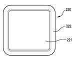
도 2b를 참조하면, 다양한 실시예에 따른 웨어러블 장치의 본체(220)는 디스플레이 영역(221)과, 비 디스플레이 영역인 베젤 영역(222)을 포함할 수 있다. 웨어러블 장치를 정면에서 보았을 때, 디스플레이 영역(221)은 대략적으로 정사각형이고, 베젤 영역(222)은 디스플레이 영역을 감싸는 형상일 수 있다. 다양한 실시예에 따르면 각진 영역(모서리)은 곡률을 가지게 구성할 수 있다.Referring to FIG. 2B, the
도 2c를 참조하면, 다양한 실시예에 따른 웨어러블 장치의 본체(230)는 디스플레이 영역(231)과, 비 디스플레이 영역인 베젤 영역(232)을 포함할 수 있다. 웨어러블 장치를 정면에서 보았을 때, 디스플레이 영역(231)은 원형이고, 베젤 영역(232)은 디스플레이 영역(231)을 감싸는 대략적으로 내부 공간이 비어 있는(중공형;hollow) 정사각형일 수 있다.Referring to FIG. 2C, the
도 2d를 참조하면, 다양한 실시예에 따른 웨어러블 장치의 본체(240)는 디스플레이 영역(241)과, 비 디스플레이 영역인 베젤 영역(242)을 포함할 수 있다. 웨어러블 장치를 정면에서 보았을 때, 디스플레이 영역(241)은 대략적으로 직사각형이고, 베젤 영역(242)은 디스플레이 영역(241)을 감싸는 형상일 수 있다. 다양한 실시예에 따르면 각진 영역(모서리)은 곡률을 가지게 구성할 수 있다.Referring to FIG. 2D, the
도 2e를 참조하면, 다양한 실시예에 따른 웨어러블 장치의 본체(250)는 디스플레이 영역(251)과, 비 디스플레이 영역인 베젤 영역(252)을 포함할 수 있다. 웨어러블 장치를 정면에서 보았을 때, 디스플레이 영역(251)은 대략적으로 타원형이고, 베젤 영역(252)은 디스플레이 영역(251)을 감싸는 형상일 수 있다. 다양한 실시예에 따르면 각진 영역(모서리)은 곡률을 가지게 구성할 수 있다.Referring to FIG. 2E, the
도 3a는 본 발명의 다양한 실시예에 따른 웨어러블 장치에서 디스플레이 오프 상태인 경우, 제1부재와 제2부재를 나타내는 도면이다. 도 3b는 본 발명의 다양한 실시예에 따른 웨어러블 장치에서 디스플레이 온 상태인 경우, 베젤 영역으로 이동한 제1부재와 제2부재를 나타내는 도면이다.3A is a view showing a first member and a second member in a display-off state in a wearable device according to various embodiments of the present invention. FIG. 3B is a view showing a first member and a second member moved to a bezel region in a display-on state in a wearable device according to various embodiments of the present invention.
도 3a, 도 3b를 참조하면, 다양한 실시예에 따른 웨어러블 장치(300)는 본체(310), 디스플레이 영역(311), 베젤 영역(312), 제1부재(320) 및 제2부재(321), 구동부(330,331)를 포함할 수 있다. 상기 웨어러블 장치(300)는 도 1a 내지 도 1c에 도시된 웨어러블 장치(100)일 수 있다.3A and 3B, a
다양한 실시예에 따른 웨어러블 장치(300)는 본체(310) 전면에 배치된 디스플레이 온 상태 또는 오프 상태에 따라 제1부재(320) 및 제2부재(321)을 이동가능하게 구성할 수 있다. 디스플레이 오프 상태에서는 제1부재(320) 및 제2부재(321)가 디스플레이 영역(311)에 배치되어, 시간을 표시할 수 있다. 디스플레이 온 상태에서, 제1부재(320) 및 제2부재(321)은 디스플레이 영역(311)에서 베젤 영역(312)으로 각각 이동하여 사용자에게서 숨겨지게 배치될 수 있다.The
다양한 실시예에 따른 웨어러블 장치(300)는 프로세서가, 디스플레이 활성 여부를 판단하고, 상기 판단에 따라, 상기 디스플레이가 활성화된 경우(온 상태), 상기 제1부재(320) 및/또는 상기 제2부재(321)를 제1형상으로 고정시켜서 상기 디스플레이를 가리지 않게 배치할 수 있다. 또한, 상기 디스플레이가 비활성화된 경우(오프 상태), 상기 제1부재(320) 및/또는 상기 제2부재(321)를 제2형상으로 고정시켜서 시각을 지시할 수 있다.The
다양한 실시예에 따른 웨어러블 장치(300)는 프로세서가, 디스플레이 활성 여부를 판단하고, 상기 판단에 따라, 상기 디스플레이가 활성화된 경우, 상기 제1부재(320)의 제2단부 및 상기 제2부재(321)의 제2단부가 상기 디스플레이의 중심 부분에서 서로 인접하도록, 상기 제1부재(320) 및/또는 상기 제2부재(321)를 상기 제1형상으로 고정시켜서 상기 디스플레이를 가리지 않게 할 수 있다. 또한, 디스플레이가 비활성화된 경우, 상기 제1부재(320)의 제2단부 및 상기 제2부재의 제2단부가 상기 하우징의 측면의 내면에 접촉하도록, 상기 제 1부재(320) 및/또는 상기 제2부재(321)를 상기 제2형상으로 고정시켜서 시각을 지시할 수 있다. 예를 들어, 다양한 실시예에 따른 제1,2부재(320,321)는 각각 형상기억합금 및 저항체에 각각 결합되되, 각 저항체에 전원이 인가되어 열이 발생하면, 전달된 열의 방사에 의해, 각각의 형상기업합금이 원위치로 복귀함으로서, 각각의 형상기억합금에 연결된 제1,2부재(320.321)도 각각 이동할 수 있다. 상기 제1,2부재(320,321)의 이동 동작(형상기억합금과 저항체의 동작)의 상세한 설명은 도 3c를 참조하여 후술하기로 한다.The
다양한 실시예에 따른 구동부(330,331)는 제1부재(320) 및 제2부재(321)를 이동하는 힘을 각각 제공하는 구동원으로서, 베젤 영역(312)에 각각 배치될 수 있다. 다양한 실시예에 따른 구동부는 제1부재(320)를 이동시키는 제1구동부(330)와, 제2부재(321)를 이동시키는 제2구동부(331)를 포함할 수 있다.The driving
후술하겠지만, 상기 제1,2구동부(330,331)는 형상기억합금 및 저항체(도 3c에 도시)의 결착에 따라 제1부재(320) 및 제2부재(321)의 이동할 수 있는 힘을 제공할 수 있다.As will be described later, the first and
다양한 실시예에 따른 제1구동부(330)는 제1부재(320) 일단이 고정되고, 베젤 영역(312)에 배치될 수 있다. 디스플레이 오프된 상태에서, 제1부재(320)는 디스플레이 영역(311)에서 선형의 제1형상으로 배치되어, 시간을 나타낼 수 있다. 디스플레이 온 상태에서, 제1부재(320)는 제1구동부(330), 예를 들어, 저항체의 열 발생으로 인한 형상기억합금의 변형에 의해 베젤 영역(312)으로 이동하여 배치될 수 있다. 제1부재(320)는 형상기억합금의 변형에 의한 제2형상으로 베젤 영역(312)을 따라 수용될 수 있다. 제1부재(320)은 제1고정부(340)에 의해 베젤 영역(312)에서 유동이 방지될 수 있다.The
다양한 실시예에 따른 제2구동부(331)는 제2부재(321) 일단이 고정되고, 베젤 영역(312)에 배치될 수 있다. 디스플레이 오프된 상태에서, 제2부재(321)는 디스플레이 영역(311)에서 제1형상(선형)으로 배치되어, 분을 나타낼 수 있다. 디스플레이 온 상태에서, 제2부재(321)는 제2구동부(331), 즉 저항체의 열 발생으로 인한 형상기억합금의 변형에 의해 베젤 영역(312)으로 배치될 수 있다. 제2부재(321)는 형상기억합금의 변형에 의한 제2형상(곡형 또는 곡률을 가지는 형상)으로 베젤 영역(312)을 따라 수용될 수 있다. 제2부재(321)는 제2고정부(341)에 의해 베젤 영역(312)에서 유동이 방지될 수 있다.The
다시, 디스플레이가 온되면, 상기 제1,2부재(320,321)는 각 형상기억합금의 원래의 모양으로 원복함에 따라서, 제1형상으로 각각 복귀할 수 있다.Again, when the display is turned on, the first and
다양한 실시예에 따른 제1부재(320)는 상하우징의 측면의 내면의 일부와 접촉하며 상기 내면을 따라 이동 가능하도록 구성된 제1단면과, 상기 제1단면의 반대편의 제2단면을 포함할 수 있다. 다양한 실시예에 따른 제2부재(321)는 하우징의 측면의 내면의 다른 일부와 접촉하며 상기 제1부재(320)와 독립적으로 상기 내면을 따라 이동 가능하도록 구성된 제1단면과, 상기 제1단면의 반대편의 제2단면을 포함할 수 있다.The
또한, 다양한 실시예에 따른 제1부재(320)의 적어도 일부는 제1색상 물질로 덮일 수 있고, 제2부재(321)의 적어도 일부는 제2색상 물질로 덮일 수 있다. 또한, 제1부재(320)에서, 제1색상의 물질로 덮인 영역의 길이는 제2부재(321)의 제2색상 물질로 덮인 영역의 길이보다 길게 구성될 수 있다.Also, at least a portion of the
다양한 실시예에 따른 제1부재(320)는 짧게 보이는 부분이 시침으로 보이기 위해서, 짧게 보이는 부분의 남은 부분을 투명 등의 다른 소재를 붙이거나, 다른 색상으로 덮어질 수 있다.The
다양한 실시예에 따른 웨어러블 장치(300)는 제1부재(320)가 베젤 영역(312)으로 이동한 후, 이동 후 상태를 고정하는 제1고정 부재(340)를 포함할 수 있다. 예를 들어, 웨어러블 장치(300)는 상기 제1부재(320)의 제2단면을 하우징의 측면의 내면에 고정시키고, 상기 내면을 따라 이동 가능하도록 구성된 제1고정 부재(340)를 더 포함할 수 있다. 다양한 실시예에 따른 웨어러블 장치(300)는 제2부재(321)가 베젤 영역(312)으로 이동한 후, 이동 후 상태를 고정하는 제2고정 부재(341)를 포함할 수 있다. 예를 들어, 웨어러블 장치(300)는 상기 제2부재(321)의 제2단면을 하우징의 측면의 내면에 고정시키고, 상기 내면을 따라 이동 가능하도록 구성된 제2고정 부재(341)를 더 포함할 수 있다.The
도 3c는 본 발명의 다양한 실시예에 따른 웨어러블 장치에서 제1부재와 제2부재를 이동시키기 전과 후의 구동부 상태를 나타내는 도면이다.3C is a view showing the state of a driving unit before and after moving the first member and the second member in the wearable device according to various embodiments of the present invention.
도 3c를 참조하면, 다양한 실시예에 따른 구동부는 제1,2구동부(330,331)를 포함할 수 있다. 상기 제1,2구동부(330,331)는 동일한 구성으로 이루어질 수 있으며, 제1구동부(330)를 대표적으로 설명하기로 한다.Referring to FIG. 3C, the driving unit according to the various embodiments may include the first and
다양한 실시예에 따른 제1구동부(330)는 제1구동 부분(3300)과, 형상기억합금(3301)(이하 합금이라 지칭한다)과, 저항체(3302)로 구성될 수 있다. 제1구동부(330)는 제1구동 부분(3300)과, 합금(3301)과, 저항체(3302)가 서로 결착된 구성으로 이루어질 수 있다. 합금(3301)은 저항체(3302)가 결착된 구성으로 이루어질 수 있다. 합금(3301)은 온도에 의해 원래의 형상과, 이후의 형상으로 변형될 수 있다. 원래의 합금(3301) 형상은 도 3c의 (a)의 형상일 수 있으며, 이후의 형상은 도 3c의 (b)의 형상일 수 있다. 저항체(3302)는 전원이 인가되면, 열이 발생하여 온도가 올라가는 발열체일 수 있다. 저항체(3302)의 열 발생에 의해 합금(3301)의 변형이 일어나고, 이러한 변형이 제1부재(320) 및/또는 제2부재(321)의 이동힘일 수 있다.The
도 3c의 (a) 상태에서, 저항체(3302)에 전원을 인가하면, 상기 저항체(3302)는 발열을 하게 되고, 상기 저항체(3302)와 결착된 합금(3301)은 변형을 할 수 있다. 변형이 발생한 합금(3301)에 의해 제1부재(320)나 제2부재(321;도 3b)는 이동을 할 수 있다. 도 3c의 (a)와 같은 상태는 도 3a와 같은 제1부재 및/또는 제2부재 상태를 나타내고, 도 3c의 (b)와 같은 상태는 도 3b와 같은 제1부재 및/또는 제2부재 상태를 나타낼 수 있다.In the state (a) of FIG. 3 (c), when power is applied to the
도 4a는 본 발명의 다양한 실시예에 따른 웨어러블 장치의 본체 내부 구성을 개략적으로 나타내는 단면도이다. 도 4b는 본 발명의 다양한 실시예에 따른 웨어러블 장치의 본체 내부 구성을 개략적으로 나타내는 단면도이다.4A is a cross-sectional view schematically showing the internal structure of a wearable device according to various embodiments of the present invention. FIG. 4B is a cross-sectional view schematically showing the internal structure of a wearable device according to various embodiments of the present invention. FIG.
도 4a, 도 4c를 참조하여 본 발명의 다양한 실시예에 따른 웨어러블 장치(400)의 본체(410)의 구조에 대해서 설명하기로 한다. 다양한 실시예에 따른 웨어러블 장치(400)는 도 1a에 도시된 웨어러블 장치(100)와 동일한 장치이거나, 적어도 일부가 동일한 장치일 수 있다. 다양한 실시예에 따른 웨어러블 장치(400)는 도 3a에 도시된 웨어러블 장치(300)와 동일한 장치이거나, 적어도 일부가 동일한 장치일 수 있다.The structure of the main body 410 of the wearable device 400 according to various embodiments of the present invention will be described with reference to FIGS. 4A and 4C. The wearable device 400 according to various embodiments may be the same device as the
다양한 실시예에 따른 웨어러블 장치(400)의 본체(410)는 하우징(401)과, 윈도우(412)와, 디스플레이(414)와, 제어부(416)를 포함하는 기판과, 배터리(418)를 포함할 수 있다.The body 410 of the wearable device 400 according to various embodiments includes a housing 401, a
다양한 실시예에 따른 본체(410)는 윈도우(412)와 하우징(401)에 의해 외관을 형성할 수 있다. 윈도우(412)는 유리나 투명 플라스틱 재질 등으로 구성될 수 있다.The body 410 according to various embodiments may form an appearance by the
다양한 실시예에 따른 제어부(416)는 기판에 장착되어서, 디스플레이(414) 및 제1,2구동부(430,431)의 동작을 제어할 수 있다. 상기 제어부(416)는 디스플레이(414)가 온 상태일 경우, 제1,2구동부(430,431)의 각 저항체를 동작시켜서, 제1부재(420) 및 제2부재(421)가 이동하는 동작을 제어할 수 있다. 다양한 실시예에 따른 윈도우(412)와 디스플레이(414) 사이에 제1부재(420)와 제2부재(421)가 장착되되, 그 사이의 공간에서 각각 이동할 수 있고, 제1,2구동부(430431)가 제1부재 및/또는 제2부재의 이동 힘을 제공할 수 있다. 디스플레이(414)는 터치 패널이 구비되어 터치 스크린으로 동작할 수 있다.The
다양한 실시예에 따른 제1부재(420)는 제1레일(420a)을 따라 이동하면서 시간을 나타낼 수 있다. 제1레일(420a)은 링형일 수 있다. 다양한 실시예에 따른 제2부재(421)는 제2레일(421a)을 따라 이동하면서 분을 나타낼 수 있다. 제2레일(421a)은 링형일 수 있다. 다양한 실시예에 따른 제1,2레일(420a,421a)은 각각 제1,2베젤 영역일 수 있다. 예컨데, 제1,2레일(420a,421a)은 미도시된 구동 장치, 예컨대 모터와 같은 장치에 의해 회전가능하게 구동되고 제어될 수 있다.다양한 실시예에 따른 디스플레이가 활성화된 경우(온 상태), 상기 제1부재(420) 및/또는 상기 제2부재(421)를 제1형상(도 4c상태)으로 고정시켜서, 상기 디스플레이를 가리지 않게 배치할 수 있다. 또한, 디스플레이가 비활성화된 경우(오프 상태), 상기 제1부재(420) 및/또는 상기 제2부재(421)를 제2형상(도 4b 상태)으로 고정시켜서 시각을 지시할 수 있다.The
예를 들어, 다양한 실시예에 따른 제1,2부재(420,421)는 각각 제1,2레일(420a,421a)에 각각 실장된 제1,2구동부(430,431)가 제공하는 힘에 의해 변형힘을 제공받을 수 있다. 다앙한 실시예에 따른 형상기억합금 및 저항체에 각각 결합된 제1,2구동부(430,431)에서, 각 저항체에 전원이 인가되어 열이 발생하면, 전달된 열의 방사에 의해, 각각의 형상기업합금이 원위치로 복귀함으로서, 각각의 형상기억합금에 연결된 제1,2부재(420.421)도 각각 제1,2레일(420a,421a)로 이동할 수 있다. 상기 제1,2부재(420,421)의 이동 동작(형상기억합금과 저항체의 동작)의 상세한 설명은 도 3b를 참조하여 설명하였기 때문에 생략하기로 한다.For example, the first and
도 4d를 참조하면, 다양한 실시예에 따른 웨어러블 장치(4000)는 도 1a에 도시된 웨어러블 장치(100)와 동일한 장치이거나, 적어도 일부가 동일한 장치일 수 있다. 다양한 실시예에 따른 웨어러블 장치(4000)는 도 3a에 도시된 웨어러블 장치(300)와 동일한 장치이거나, 적어도 일부가 동일한 장치일 수 있다. 다양한 실시예에 따른 웨어러블 장치(4000)는 도 4a에 도시된 웨어러블 장치(400)와 동일한 장치이거나, 적어도 일부가 동일한 장치일 수 있다.Referring to FIG. 4D, the
다양한 실시예에 따른 하우징(4010)은 디스플레이(4140), 제어부(4160) 및 배터리(4180) 등을 수용하여 보호하며, 외관을 담당하는 케이스로서, 합성 수지나 금속이나, 이들의 조합으로 구성될 수 있다. 하우징(4010)이 적어도 일부나 전부가 금속 재질로 구성될 경우, 하우징(4010)의 적어도 일부를 구성하거나, 적어도 일부 테두리를 구성하는 복수 개의 분절 외관 금속 프레임이 안테나 방사체 역할을 겸할 수 있다.The
다양한 실시예에 따른 디스플레이(4140)는 평탄하게 구성하거나, 곡면으로 구성할 수 있다. 디스플레이(4140)가 곡면으로 구성될 경우, 전부 또는 일부를 곡률을 가지게 구성할 수 있다. 곡률을 가진 영역은 디스플레이(4140)의 엣지 영역일 수 있다. 디스플레이(4140) 상에 제1부재(4200)와 제2부재(4210)가 배치되어 이동가능하게 구성될 수 있다.The
다양한 실시예에 따른 각각의 제1,2부재(4200,4210)는 하우징의 단면에서 볼 때, 서로 중첩하지 않게 배치될 수 있다. 제1부재(4200)가 제2부재(4201)보다 상측에 배치될 수 있다.Each of the first and
다양한 실시예에 따른 제1구동부(4300)는 제1부재(4200)와 대략 동일한 면을 따라 배치되고, 제2구동부(4310)는 제2부재(4210)와 대략 동일한 면을 따라 배치될 수 있다.The
도 5는 본 발명의 다양한 실시예에 따른 웨어러블 장치의 본체 전면을 나타내는 단면도이다.5 is a cross-sectional view showing a main body front of a wearable device according to various embodiments of the present invention.
도 5를 참조하여 본 발명의 다양한 실시예에 따른 웨어러블 장치(500)의 구성에 대해서 설명하기로 한다. 도 5를 참조하면, 다양한 실시예에 따른 웨어러블 장치(500)는 도 3a 내지 도 3c에 도시된 웨어러블 장치(300)와 비교하여, 시간과 분을 나타내는 제1,2부재(구형 오브젝트)가 침 형상이 아니라, 금속 재질의 볼(볼 베어링) 형상인 점에서 차이가 있을 수 있고, 이를 구동하는 구동부의 구성이 상이할 수 있다.The configuration of the
다양한 실시예에 따른 웨어러블 장치(500)는 본체(510)와, 본체(510) 전면에 배치된 디스프레이 영역(511)과, 제1베젤 영역(512)과, 제2베젤 영역(513)과, 시간을 나타내는 제1구형 오브젝트(520)와, 분을 나타내는 제2구형 오브젝트(521) 및 제1,2오브젝트(520,521)를 이동시키는 힘을 제공하는 구동부(도 6a)를 포함할 수 있다. 또한, 제1구형 오브젝트(520)가 분을 나타낼 수 있고, 제2구형 오브젝트(521)가 시간을 나타낼 수 있다. 구동부의 상세한 구성은 도 7에서 설명하기로 한다.The
다양한 실시예에 따른 웨어러블 장치(500)는 디스플레이 온 상태 또는 오프 상태에 따라 시간을 나타내는 제1구형 오브젝트(520) 및 분을 나타내는 제2구형 오브젝트(521)를 각각 이동가능하게 구성할 수 있다. 디스플레이 오프 상태에서는 제1구형 오브젝트(520) 및 제2구형 오브젝트(521)가 각각 제1,2베젤 영역(512.513)에 배치되어서, 시간 및 분을 각각 시각적 또는 촉각적으로 표시할 수 있다.The
디스플레이 온 상태에서, 제1오브젝트(520) 및 제2오브젝트(521)는 제1,2베젤 영역(512,513)에 각각 배치되어, 제1,2베젤 영역(512,513) 내에 각각 사용자에게 숨겨지게 배치될 수 있다. 제1,2베젤 영역(512,513)은 각각 구분되게 배치되어, 각각 미도시된 구동부(도 6a)에 의해 동작이 제어될 수 있다.In the display-on state, the
다양한 실시예에 따른 웨어러블 장치(500)는 디스플레이 및 적어도 하나의 전자석과 전기적으로 연결된 프로세서 및 메모리를 포함할 수 있다. 메모리는, 실행시에, 상기 프로세서가, 장치에서 실행되는 적어도 하나의 액션에 기초하여, 상기 적어도 하나의 물리적 경로를 따라 상기 적어도 하나의 구동부를 이동시키도록 하는 인스트럭션들을 저장할 수 있다.The
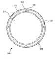
다양한 실시예에 따른 웨어러블 장치(500)는 제1물리적 경로인 제1베젤 영역(512)과, 제2물리적 경로인 제2베젤 영역(513)을 포함할 수 있다. 제1베젤 영역(512)은 디스플레이 영역(511) 둘레를 따라 폐루프 형상으로 제1물리적 경로(트랙)을 제공할 수 있고, 제2베젤 영역(513)은 제1베젤 영역(512) 둘레 바깥쪽으로 연장된 제2물리적 경로(트랙)를 제공할 수 있다.The
다양한 실시예에 따른 제1구형 오브젝트(520)는 상기 제1물리적 경로를 따라 이동 가능하도록 배치될 수 있고, 제2구형 오브젝트(521)는 제2물리적 경로를 따라 이동 가능하도록 배치될 수 있다.The first
다양한 실시예에 따른 제1,2구형 오브젝트(520,521)는 제1,2구동부에 의해 각각 제1,2물리적 경로를 따라 이동하는 힘을 각각 제공받을 수 있다. 후술하겠지만, 제1,2구동부는 전자석을 각각 채용할 수 있다. 각각의 제1,2구동부는 각각 제1,2물리적 경로를 따라 이동가능하게 배치될 수 있다.The first and second
다양한 실시예에 따른 웨어러블 장치는 프로세서를 포함할 수 있다. 프로세서의 의해 실행되는 인스트럭션들은, 선택된 시각의 시(hour)에 대응하는 상기 제1물리적 경로 상의 제1위치에 인접하도록 상기 제1전자석을 이동시키고, 선택된 시각의 분(minute)에 대응하는 상기 제2물리적 경로 상의 제2위치에 인접하도록 상기 제2전자석을 이동시킬 수 있다.A wearable device according to various embodiments may include a processor. Instructions executed by the processor move the first electromagnet such that the first electromagnet is adjacent to a first position on the first physical path corresponding to an hour of the selected time, Lt; RTI ID = 0.0 > 2 < / RTI > physical path.
도 6a, 도 6b는 본 발명의 다양한 실시예에 따른 웨어러블 장치의 본체 내부 구성을 개략적으로 각각 나타내는 단면도이다.6A and 6B are cross-sectional views each schematically showing the internal structure of a wearable device according to various embodiments of the present invention.
도 6a를 참조하면, 다양한 실시예에 따른 웨어러블 장치(600)의 본체(610)는 하우징(601)과, 윈도우(612)와, 디스플레이(614)와, 제1,2구형 오브젝트(620,621)와, 구동부(630)와, 제어부(616)를 포함하는 기판과, 배터리(618)를 포함할 수 있다.6A, the
다양한 실시예에 따른 본체(610)는 윈도우(612)와 하우징(601)에 의해 외관을 형성할 수 있다. 윈도우(612)는 유리나 투명 플라스틱 재질 등과 같은 투명 기판으로 구성될 수 있다.The
다양한 실시예에 따른 하우징(601)은 디스플레이(614), 제1,2오브젝트(620,621), 구동부(630), 제어부(616) 및 배터리(618) 등을 수용하여 보호하며, 외관을 담당하는 케이스로서, 합성 수지나 금속이나, 이들의 조합으로 구성될 수 있다. 하우징(601)이 적어도 일부나 전부가 금속 재질로 구성될 경우, 하우징(601)의 적어도 일부를 구성하거나, 적어도 일부 테두리를 구성하는 복수 개의 분절 외관 금속 프레임이 안테나 방사체 역할을 겸할 수 있다.The
다양한 실시예에 따른 디스플레이(614)는 평탄하게 구성하거나, 곡면으로 구성할 수 있다. 디스플레이(614)가 곡면으로 구성될 경우, 전부 또는 일부를 곡률을 가지게 구성할 수 있다. 곡률을 가진 영역은 디스플레이(614)의 엣지 영역일 수 있다. 디스플레이(614) 상에 제1구형 오브젝트(620)와, 제2구형 오브젝트(621)가 각각 구동부에 의해 이동가능하게 배치될 수 있다.The
다양한 실시예에 따른 제어부(프로세서)(616)는 기판에 장착되어서, 디스플레이(614) 및 구동부(630)의 동작을 제어할 수 있다. 다양한 실시예에 따른 윈도우(612)와 디스플레이(614) 사이에 제1구형 오브젝트(620)와, 제2구형 오브젝트(621)가 장착되되, 그 사이의 공간에서 각각 이동할 수 있고, 구동부(630)가 제1,2오브젝트의 이동 힘을 제공할 수 있다. 디스플레이(614)는 터치 패널이 구비되어 터치 스크린으로 동작할 수 있다. 구동부(630)는 마그네트의 힘을 이용하거나, 전자석 또는 이들의 조합을 이용할 수 있다. 구동부(630)는 제1,2구형 오브젝트(620,621)를 각각 구동시키는 제1,2전자석을 포함할 수 있다.A controller (processor) 616 according to various embodiments may be mounted on the substrate to control the operation of the
다양한 실시예에 따른 제1구형 오브젝트(620)는 본체 전면에 배치되되, 볼 베어링 타입으로, 제1베젤 영역 상을 트랙으로 간주하여 구동부(630)에서 제공하는 힘에 의해 이동할 수 있다. 제1구형 오브젝트(620)는 시간을 표시할 수 있다. 다양한 실시예에 따른 제2구형 오브젝트(621)는 본체 전면에 배치되되, 볼 베어링 타입으로, 제2베젤 영역 상을 트랙으로 간주하여 구동부(630)에서 제공하는 힘에 의해 이동할 수 있다. 제2오브젝트(621)는 구동부 상의 트랙을 구르는 동작으로, 제1구형 오브젝트(620)보다 작은 직경크기로 구성되어, 분을 표시할 수 있다.The first
도 6b를 참조하면, 다양한 실시예에 따른 웨어러블 장치(650)는 도 6a에 도시된 웨어러블 장치일 수 있다. 다양한 실시에에 따른 웨어러블 장치(650)는 제2구형 오브젝트(671)가 케이스(651) 측면에 노출되게 배치될 수 있다. 케이스(651) 측면에 배치된 제2구형 오브젝트(671)는 구동부(660)에 의해 이동할 수 있다. 제1구형 오브젝트(670)는 케이스(651) 전면에 배치될 수 있다.Referring to FIG. 6B, the
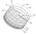
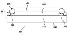
도 6c를 참조하면, 다양한 실시예에 따른 웨어러블 장치(680)는 윈도우(682)와, 디스플레이(684)와, 제1,2구형 오브젝트(690,691)와, 구동부(692)와, 제어부(686)를 포함하는 기판과, 배터리(688)를 포함할 수 있다.6C, a
다양한 실시예에 따른 각각 시간과 분을 알려주는 제1,2구형 오브젝트(690,691)는 적층되는 구조로 실장할 수 있다. 다양한 실시예에 따른 제1오브젝트(690)가 제2오브젝트(691)보다 상방쪽에 실장될 수 있다. 다양한 실시예에 따른 제1오브젝트(690)가 제2오브젝트(691)보다 외부쪽에 실장될 수 있다. 다양한 실시예에 따른 제1오브젝트(690) 및 제2오브젝트(691)는 경사진 방향을 따라서 나란하게 실장될 수 있다.The first and second
도 7은 본 발명의 다양한 실시예에 따른 웨어러블 장치에서 구동부에 의해 이동하는 오브젝트 상태를 순차적으로 각각 나타내는 도면이다.FIG. 7 is a diagram sequentially showing object states moved by a driving unit in a wearable device according to various embodiments of the present invention; FIG.
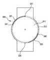
도 7을 참조하면, 다양한 실시예에 따른 웨어러블 장치는 구동부의 이동에 따라서 구형 오브젝트가 이동할 수 있다. 예컨대, 제1베젤 영역(제1물리적 경로)를 따라서 이동하는 제1전자석과, 제2베젤 영역(제2물리적 경로)를 따라서 이동하는 제2전자석의 원리는 동일하기 때문에, 제1물리적 경로를 따라서 이동하는 제1전자석의 동작에 대해서만 설명하기로 한다.Referring to FIG. 7, in the wearable apparatus according to various embodiments, the spherical object can move according to the movement of the driving unit. For example, since the principle of the first electromagnet moving along the first bezel region (first physical path) and the second electromagnet moving along the second bezel region (second physical path) are the same, the first physical path Therefore, only the operation of the moving first electromagnet will be described.
다양한 실시예에 따른 제1전자석(730)은 제1경로(712)를 따라 순차적으로 이동하면, 제1구형 오브젝트(720)도 함께 순차적으로 이동할 수 있다. 제1경로(712)는 등간격으로 분절형 트랙(요철 형상;714,715)으로 구성할 수 있다. 제1전자석(730)은 미도시된 모터 등에 의해 제1경로(712)를 따라 이동할 수 있다.As the
시간이 변경되어 시침 또는 분침이 이동하는 경우, 전자석(730)이 먼저 이동하고((a)→(b)), 이어서 전자석(730)에 의해 발생한 자성에 의해서 제1구형 오브젝트(720)가 이동하며((a)→(b)→(c)), 제1구형 오브젝트가 안착부에(715)에 완전히 이동되면, 전자석(720)에 자성이 사라질 수 있다.(e) 제1구형 오브젝트(720)는 트랙 상의 요철 부분(714,715)을 자성에 의해 구르는 방식으로 이동할 수 있다. 홈 같은 부분(715)에 제1오브젝트(720)가 안착된 경우, 제1오브젝트(720)는 시간의 정시를 나타낼 수 있다.The
도 8은 본 발명의 다양한 실시예에 따른 웨어러블 장치의 제1부재와 제2부재를 나타내는 도면이다.8 is a view showing a first member and a second member of a wearable device according to various embodiments of the present invention.
도 8을 참조하면, 다양한 실시예에 따른 웨어러블 장치(800)는 본체(810), 디스플레이 영역(811), 베젤 영역(812), 비 디스플레이 영역(813), 제1부재(820) 및 제2부재(821)를 포함할 수 있다.8, a
다양한 실시예에 따른 웨어러블 장치(800)는 도 3a, 돌 3b에 도시된 웨어러블 장치(300)와 비교하여, 디스플레이 영역이 상이하고, 제1부재 및 제2부재의 길이가 상이한 점이 있을 수 있다.The
다양한 실시예에 따른 웨어러블 장치(800)는 위에서 보았을 때, 전면이 원형으로 구성될 수 있다. 웨어러블 장치(800)의 본체 전면은 중앙에 배치된 원형의 디스플레이 영역(811)과, 디스플레이 영역(811)과 이격되게 동심으로 배치된 베젤 영역(812)과, 상기 디스플레이 영역(811)과 베젤 영역(812) 사이에 배치된 비 디스플레이 영역(813)을 포함할 수 있다.The
다양한 실시예에 따른 비 디스플레이 영역(813)은 디스플레이 온/오프 시에 제1부재(820) 및 제2부재(821)가 배치되어, 시간 및 분을 각각 나타내는 영역일 수 있다. 한편, 비 디스플레이 영역(813)은 디스플레이 온 시에 디스플레이 영역(811)과 함께 시간 및 분을 각각 나타내는 영역(도 16a, 도 16b 참조)일 수 있다.The
비 디스플레이 영역(813)은 링 형상으로, 디스플레이 영역(811)과, 베젤 영역(813) 사이에 배치될 수 있다. 비 디스플레이 영역(813)은 제1부재(820) 및 제2부재(821)를 제외하면, 빈 공간으로 구성될 수 있고, 외부에서 보일 수 있는 영역일 수 있다. 비 디스플레이 영역(813)은 디스플레이 영역(811)을 감싸게 배치될 수 있다.The
다양한 실시예에 따른 베젤 영역(812)은 비 디스플레이 영역이지만, 외부에서 보이지 않은 비 디스플레이 영역일 수 있다.The
다양한 실시예에 따른 디스플레이 영역(811), 비 디스플레이 영역(813) 및 베젤 영역(812)의 형상은 한정될 필요는 없다. 도 2a 내지 도 2e에 도시된 다양한 디스플레이 영역 및 비 디스플레이 영역의 형상이 적용될 수 있다.The shape of the
도 9는 본 발명의 다양한 실시예에 따른 웨어러블 장치의 본체 내부 구성을 개략적으로 나타내는 단면도이다.FIG. 9 is a cross-sectional view schematically showing the internal structure of a wearable device according to various embodiments of the present invention.
도 9를 참조하여 본 발명의 다양한 실시예에 따른 웨어러블 장치(900)의 본체(910)의 상하 적층 구조에 대해서 설명하기로 한다. 도 9에 도시된 웨어러블 장치는 도 8에 도시된 웨어러블 장치(800)와 동일한 장치일 수 있다.9, the upper and lower laminated structures of the
다양한 실시예에 따른 웨어러블 장치(900)의 본체(910)는 하우징(901)과, 윈도우(912)와, 디스플레이(914)와, 제어부(916)를 포함하는 기판과, 배터리(918)를 포함할 수 있다.The
다양한 실시예에 따른 본체(910)는 윈도우(912)와 하우징(901)에 의해 외관을 형성할 수 있다. 윈도우(912)는 유리나 투명 플라스틱 재질 등으로 구성될 수 있다.The
다양한 실시예에 따른 하우징(901)은 디스플레이(914), 제어부(916) 및 배터리(918) 등을 수용하여 보호하며, 외관을 담당하는 케이스로서, 합성 수지나 금속이나, 이들의 조합으로 구성될 수 있다. 하우징(901)이 적어도 일부나 전부가 금속 재질로 구성될 경우, 하우징(901)의 적어도 일부를 구성하거나, 적어도 일부 테두리를 구성하는 복수 개의 분절 외관 금속 프레임이 안테나 방사체 역할을 겸할 수 있다.The
다양한 실시예에 따른 디스플레이(914)는 평탄하게 구성하거나, 곡면으로 구성할 수 있다. 디스플레이(914)가 곡면으로 구성될 경우, 전부 또는 일부를 곡률을 가지게 구성할 수 있다. 곡률을 가진 영역은 디스플레이(914)의 엣지 영역일 수 있다.The
다양한 실시예에 따른 디스플레이(914)의 디스플레이 영역은 도 8에 도시된 디스플레이 영역과 동일하게 구성될 수 있다. 케이스(901)와 디스플레이(914) 사이에 비디스플레이(913) 영역이 배치될 수 있다.The display area of the
다양한 실시예에 따른 제1부재(920)와 제2부재(921)는 각각 디스플레이(914)와 적층되지 않고, 나란하게 배치되어 구동될 수 있다. 즉, 제1부재(920) 및 제2부재(921)는 디스플레이(914)와 적층되지 않고 대략적으로 평행하게 배치되어 시간 및 분을 표시할 수 있다. 또한, 다양한 실시예에 따른 제1부재(920) 및 제2부재(921)는 디스플레이(914) 하측에 각각 배치될 수 있고, 외부에서 봤을 때, 상기 디스플레이(914) 하측에 각각 숨겨지게 배치될 수 있다.The
다양한 실시예에 따른 제1부재(920) 및 제2부재(921)는 제1,2구동부(930,931)에 의해 비디스플레이 영역(913)에서 시침과 분침을 각각 나타내거나, 디스플레이(914) 하측에 각각 숨겨지게 배치될 수 있다.The
다양한 실시예에 따른 제1,2구동부(930,931)는 기판에 배치되어 제어부에 의해 제어될 수 있다. 상기 각각의 제1,2구동부(930,931)는 디스플레이(914) 하측에 각각 배치되어, 제1,2부재(920,921)를 각각 이동시키는 힘을 제공할 수 있다. 다양한 실시예에 따른 제1,2구동부(930,931)의 구성 및 동작은 도 3c에 상세히 설명하였기 때문에 생략하기로 한다.The first and
다양한 실시예에 따른 제어부(916)는 기판에 장착되어서, 디스플레이(914) 및 제1,2구동부(930,931)의 동작을 제어할 수 있다. 상기 제어부(916)는 디스플레이(914)가 온 상태일 경우, 제1,2구동부(930,931)의 저항체를 동작시켜서, 제1부재(920) 및 제2부재(921)가 이동하는 동작을 제어할 수 있다.The
도 10a 내지 도 16b를 참조하여 다양한 실시예에 따른 웨어러블 장치를 이용하여 입력 가능한 동작에 대해서 설명하기로 한다.10A to 16B, operations that can be performed using the wearable device according to various embodiments will be described.
도 10a, 도 10b는 본 발명의 다양한 실시예에 따른 웨어러블 장치에서 엘이디를 이용하여 알람 도착 상태를 각각 표시하는 도면이다.FIGS. 10A and 10B are views showing alarm arrival states using LEDs in a wearable device according to various embodiments of the present invention, respectively.
도 10a를 참조하면, 다양한 실시예에 따른 웨어러블 장치(1000)는 도 1a 내지 도 1c에 도시된 웨어러블 장치(100)일 수 있다. 다양한 실시예에 따른 웨어러블 장치(1000)는 알람 수신 시, 디스플레이 오프 상태에서, 광원(1001)을 이용하여 알람 상태를 표시할 수 있다. 예를 들어, 광원(1001)으로서 LED를 이용하여 알람 상태를 표시할 수 있다. 예컨대, LED가 디스플레이 영역(1011) 중심에 배치(기판에 배치)되어 도파되면, 디스플레이가 오프된 상태에서 디스플레이 영역(1011) 중심이 조사되어서, 사용자는 알람 수신 상태를 파악할 수 있다.Referring to FIG. 10A, the
예컨대, 다양한 실시예에 따른 LED(1001)는 제1부재(1020)나 제2부재(1021) 단부(중심에 가까운 단부)에 각각 배치되어서, 알람 상태를 표시할 수 있다.For example, the
도 10b를 참조하면, 다양한 실시예에 따른 웨어러블 장치(1050)는 알람 수신 시, 디스플레이(1061) 오프 상태에서, 적어도 하나 이상의 광원(1050,1051)을 이용하여 알람 상태를 표시할 수 있다. 예를 들어, 광원으로서 제1,2LED(1050,1051)를 이용하여 알람 상태를 각각 표시할 수 있다. 예컨대, LED가 디스플레이 영역(1011)의 중심을 제외한 영역(중심 주변 영역)에 배치(기판에 배치)되어 도파되면, 디스플레이가 오프된 상태에서 디스플레이 영역(1061) 중심의 주변 영역이 조사되어서, 사용자는 알람 수신 상태를 파악할 수 있다.Referring to FIG. 10B, the
예를 들어, 다양한 실시예에 따른 제1,2LED(1050,1051)는 시침(1070) 또는 분침(1071)의 적어도 일부 또는 전부일 수 있다. 다양한 실시예에 따른 시침(1070)은 긴 부분이 제1LED(1050)로 구성되거나, 제1LED(1050)로 덧씌워질 수 있고, 분침(1071)은 전부가 제2LED(1051)로 구성되거나, 제2LED(1051)로 덧씌워질 수 있다.For example, the first and
도 11a, 도 11b는 본 발명의 다양한 실시예에 따른 웨어러블 장치에서 오브젝트 흔들림을 이용하여 알람 도착 상태를 각각 표시하는 도면이다.FIGS. 11A and 11B are views showing alarm arrival states using object shaking in a wearable device according to various embodiments of the present invention.
도 11a를 참조하면, 다양한 실시예에 따른 웨어러블 장치(1100)는 도 5 내지 도 6에 도시된 웨어러블 장치(500,600)일 수 있다. 알람 수신 시, 디스플레이 오프 상태에서, 볼 타입의 시간이나 분을 나타내는 제1오브젝트(1120)나, 제2오브젝트(1121)나, 제1,2오브젝트(1120,1121)를 이용하여 사용자에게 알람 상태를 표시할 수 있다. 예를 들어, 시간을 나타내는 제1오브젝트(1120)가 상하로 반복적 이동(상하 흔들림)이나 좌우 반복적 이동(좌우 흔들림)을 하거나, 제2부재를 나타내는 제2오브젝트(1121)가 상하로 반복적 이동을 하거나, 제1,2오브젝트(1120,1121)가 함께 상하로 반복적 이동을 하여, 사용자에게 알람 상태를 제공할 수 있다.Referring to FIG. 11A, the
도 11b를 참조하면, 다양한 실시예에 따른 웨어러블 장치(1100)는 알람 수신 시, 디스플레이 오프 상태에서, 볼 타입의 시간을 나타내는 제1오브젝트(1120)를 이용하여 사용자에게 알람 상태를 표시할 수 있다. 예를 들어, 시간을 나타내는 제1오브젝트(1120)가 대략 360도 베젤 영역을 따라 회전하여, 사용자에게 알람 상태를 제공할 수 있다. 이는 제2오브젝트도 동일하게 적용될 수 있다. 예컨대, 제2오브젝트가 대략 360도 회전하면, 알람 수신 상태를 사용자는 파악할 수 있다.Referring to FIG. 11B, the
도 12a, 도 12b는 본 발명의 다양한 실시예에 따른 웨어러블 장치의 네비게이션 모드에서 오브젝트를 이용하여 이동 방향을 각각 표시하는 도면으로, 도 12a는 디스플레이 온 상태이고, 도 12b는 디스플레이 오프 상태이다.FIGS. 12A and 12B are views showing moving directions using objects in a navigation mode of a wearable device according to various embodiments of the present invention, wherein FIG. 12A is a display-on state and FIG. 12B is a display-off state.
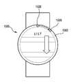
도 12a를 참조하면, 다양한 실시예에 따른 웨어러블 장치(1200)는 도 5 도 6a에 도시된 웨어러블 장치(600)일 수 있다. 다양한 실시예에 따른 웨어러블 장치(1200)는 네비게이션 모드 시, 볼 타입의 오브젝트(1220)를 이용하여 이동 방향이나, 이동하려는 방향 상태를 표시할 수 있다. 예를 들어, 오브젝트(1220)가 북동쪽 방향에 있을 경우, 이동 수단을 타고 있는 사용자는 북동쪽을 향하여 가능 중이거나, 갈 예정인 경우일 수 있다.Referring to FIG. 12A, the
다양한 실시예에 따른 웨어러블 장치(1200)는 프로세서가, 디스플레이의 적어도 일부에, 상기 전자장치의 사용자가 이동할 경로를 포함하도록 구성된 지도를 표시하고, 사용자가 상기 경로를 따라 이동할 방향에 대응하는 상기 제 1 물리적 경로 상의 제 1 위치에 인접하도록 상기 제 1 전자석을 이동시키고, 북쪽 방향에 대응하는 상기 제 2 물리적 경로 상의 제 2 위치에 인접하도록 상기 제 2 전자석을 이동시킬 수 있다.The
도 12b를 참조하면, 다양한 실시예에 따른 웨어러블 장치(1200)는 디스플레이 오프 상태에서 시, 볼 타입의 제1,2오브젝트(1220,1221)를 이용하여 이동 방향이나, 이동하려는 방향 상태를 표시할 수 있다. 예를 들어, 제1오브젝트(1220)가 북쪽 방향에 있을 경우, 이동 수단을 타고 있는 사용자는 북쪽을 향하여 가능 중이거나, 갈 예정인 경우일 수 있다. 예를 들어, 제2오브젝트(1221)가 북동쪽 방향에 있을 경우, 이동 수단을 타고 있는 사용자는 북동쪽을 향하여 가능 중이거나, 갈 예정인 경우일 수 있다.12B, the
도 13a 내지 도 13c를 참조하여 전자 잉크 등을 이용하여 기본 정보 등을 표시하는 방법에 대해서 설명하기로 한다.A method of displaying basic information or the like using electronic ink or the like will be described with reference to Figs. 13A to 13C.
다양한 실시예에 따른 웨어러블 장치(1300)는 디스플레이(1311) 상에 기본 정보와 관련된 패턴을 전자 잉크 등을 사용하여 배경으로서 실장할 수 있다.The
예컨대, 웨어러블 장치(1300)의 디스플레이(1311)가 오프된 상태에서, 디스플레이(1311) 상면에 배경으로 인쇄된 전자 잉크에 저전력으로 기본적인 정보를 표시할 수 있다.For example, in a state in which the
도 13a에 도시된 웨어러블 장치(1300)는 도 1a 내지 도 1c에 도시된 웨어러블 장치(100)일 수 있다. 다양한 실시예에 따른 웨어러블 장치는 디스플레이 오프 상태에서, 인쇄된 전자 잉크에 저전력으로 전원을 인가하면, 전자 잉크의 패턴이 배경 화면이 될 수 있다.The
도 13b에 도시된 웨어러블 장치(1350)는 도 1a 내지 도 1c에 도시된 웨어러블 장치(100)와 동일한 장치일 수 있다. 다양한 실시예에 따른 웨어러블 장치(1350)는 디스플레이(1361) 오프 상태에서, 인쇄된 전자 잉크에 저전력으로 전원을 인가하면, 전자 잉크의 패턴이 뮤직 모드를 나타낼 수 있다.The
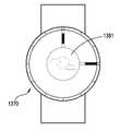
도 13c에 도시된 웨어러블 장치(1370)는 도 8에 도시된 웨어러블 장치(800)와 동일한 장치일 수 있다. 다양한 실시예에 따른 웨어러블 장치(1370)는 디스플레이(1381) 오프 상태에서, 인쇄된 전자 잉크에 저전력으로 전원을 인가하면, 전자 잉크의 패턴이 배경 날씨 정보를 나타낼 수 있다.The
예컨대, 다양한 실시예에 따른 웨어러블 장치(1370)는 디슬플레이(1381)가 오프된 상태에서, 전자 잉크를 동작시킬 정도의 저전력으로, 디스플레이를 사용하지 않고, 기본 정보를 표시할 수 있다.For example, the
도 14a, 도 14b는 본 발명의 다양한 실시예에 따른 웨어러블 장치에서 베젤 영역에 있는 오브젝트를 이용하여 입력 장치로 사용하는 상태를 각각 나타내는 도면으로서, 전화 번호를 입력하는 상태를 나타내는 도면이다.FIGS. 14A and 14B are views showing a state in which a wearable device according to various embodiments of the present invention is used as an input device using an object in a bezel area, respectively, and a state in which a telephone number is input. FIG.
도 14a를 참조하면, 볼 타입의 오브젝트(1420)를 구비한 웨어러블 장치(1400)에서는 오브젝트(1420)의 회전량에 따라 원하는 전화번호를 입력시킬 수 있다. 예를 들어, 베젤 영역(1402)을 10등분 정도 하고, 두 칸 정도를 오브젝트(1420)를 회전시키면, 전화전호 '2'가 입력되고 다시 오브젝트(1420)는 원위치로 복귀할 수 있다.Referring to FIG. 14A, a
도 14b를 참조하면, 여섯칸 정도를 오브젝트(1420)를 다시 회전시키면, 전화번호 '6'이 입력될 수 있고, 다시 원위치로 복귀할 수 있다. 이러한 방식으로 원하는 상대방 전화번호를 볼 타입 오브젝트(1420)를 이용하여, 아나로그 감성(회전 다이얼 식)으로 전화번호를 입력할 수 있다.Referring to FIG. 14B, when the
도 15는 본 발명의 다양한 실시예에 따른 웨어러블 장치(1500)에서 베젤 영역(1502)에 있는 오브젝트(1520)를 이용하여 입력 장치로 사용하는 상태를 나타내는 도면으로서, 리스트를 드래그 입력하는 상태를 나타내는 도면이다.FIG. 15 is a diagram illustrating a state in which a
도 15를 참조하면, 다양한 실시예에 따른 웨어러블 장치(1500)는 오브젝트(1520)의 회전량에 따라 원하는 표시된 리스트 업 또는 다운시킬 수 있다. 예를 들어, 베젤 영역(1502)을 몇 등분 정도 하고, 한 칸 정도를 오브젝트(1520)를 회전시키면, 리스트가 내려가게 입력될 수 있으며, 다시 오브젝트는 원위치로 복귀할 수 있다. 두 칸 정도를 오브젝트(1520)를 회전시키면, 그 이상 리스트가 내려가게 입력될 수 있고, 다시 원위치로 복귀할 수 있다.Referring to FIG. 15, the
도 16a는 본 발명의 다양한 실시예에 따른 웨어러블 장치를 나타내는 도면으로서, 디스플레이 오프 상태를 나타내는 도면이다. 도 16b는 본 발명의 다양한 실시예에 따른 웨어러블 장치를 나타내는 도면으로서, 디스플레이 온 상태를 나타내는 도면이다.16A is a view showing a wearable device according to various embodiments of the present invention, and is a view showing a display-off state. 16B is a view showing a wearable device according to various embodiments of the present invention, which shows a display-on state.
도 16a, 도 16b를 참조하면, 다양한 실시예에 따른 웨어러블 장치는 도 8에 도시된 웨어러블 장치(800)와 동일한 장치일 수 있다.16A and 16B, the wearable device according to various embodiments may be the same device as the
도 16a를 참조하면, 다양한 실시예에 따른 웨어러블 장치(1600)는 디스플레이가 오프된 상태에서, 제1부재(1620) 및/또는 제2부재(1621)를 이용해서 물리적으로 시간 및 분을 표시할 수 있다.16A, a
도 16b를 참조하면, 다양한 실시예에 따른 웨어러블 장치(1600)는 디스플레이가 온된 상태에서, 제1부재(1620) 및 제2부재(1621)를 이용해서 시간 및 분을 표시할 수 있다. 디스플레이 영역(1611)에 제1부재(1620) 및 제2부재(1621)를 완성(연장)하는 형태를 각각 디스플레이해서, 시간 및 분을 완전하게 표시할 수 있다. 디스플레이 영역(1611)에는 제1부재(1620)의 적어도 일부 영역(예를 들어 절반)와, 제2부재(1621)의 적어도 일부 영역(예를 들어 절반)이 표시될 수 있다.Referring to FIG. 16B, the
본 발명의 다양한 실시예에 따른 전자장치는 제1방향으로 향하는 제1면, 상기 제1방향에 반대인 제2방향으로 향하는 제2면, 및 상기 제 1 면 및 제 2 면 사이의 공간을 둘러싸는 측면을 포함하는 하우징; 상기 하우징의 제1면의 적어도 일부를 형성하는 투명 기판; 상기 하우징의 공간 내에 배치되고, 상기 투명 기판의 적어도 일부를 통해 노출된 디스플레이; 상기 투명 기판 및 상기 디스플레이 사이에 적어도 일부 배치되고, 물리적으로 이동 가능한 기계적 시계 구조(mechanical watch structure); 상기 디스플레이 및 상기 시계 구조에 전기적으로 연결된 프로세서; 및 상기 프로세서와 전기적으로 연결된 메모리를 포함하며, 상기 메모리는, 실행시에, 상기 프로세서가, 상기 디스플레이 및 상기 시계 구조를 제어하도록 하는 인스트럭션들을 저장할 수 있다.An electronic device according to various embodiments of the present invention includes a first surface facing in a first direction, a second surface facing in a second direction opposite to the first direction, and a space between the first surface and the second surface A housing including a side surface; A transparent substrate defining at least a portion of a first side of the housing; A display disposed within the space of the housing and exposed through at least a portion of the transparent substrate; A mechanical watch structure disposed at least partially between the transparent substrate and the display and being physically movable; A processor electrically connected to the display and the watch structure; And a memory electrically coupled to the processor, wherein the memory, upon execution, may store instructions that cause the processor to control the display and the clock structure.
본 발명의 다양한 실시예에 따른 구조는, 시(hour)를 지시하도록 이동가능한 제1부재; 및 분(minute)을 지시하도록 이동가능한 제2부재를 포함할 수 있다.A structure according to various embodiments of the present invention includes: a first member movable to indicate an hour; And a second member that is moveable to indicate a minute.
본 발명의 다양한 실시예에 따른 제1부재는, 상기 하우징의 측면의 내면의 일부와 접촉하며 상기 내면을 따라 이동 가능하도록 구성된 제1단면; 및 상기 제1단면의 반대편의 제2단면을 포함하고, 상기 제2부재는, 상기 하우징의 측면의 내면의 다른 일부와 접촉하며 상기 제1부재와 독립적으로 상기 내면을 따라 이동 가능하도록 구성된 제1단면; 및 상기 제1단면의 반대편의 제2단면을 포함할 수 있다.A first member according to various embodiments of the present invention includes a first cross-section configured to contact a portion of an inner surface of a side surface of the housing and to be movable along the inner surface; And a second end opposite the first end, wherein the second member is in contact with another portion of the inner surface of the side surface of the housing and is configured to be movable along the inner surface independently of the first member, section; And a second cross-section opposite the first cross-section.
본 발명의 다양한 실시예에 따른 인스트럭션들은, 상기 프로세서가, 상기 디스플레이가 활성화되었는지 여부를 판단하고, 상기 판단에 따라, 상기 디스플레이가 활성화된 경우, 상기 제1부재 및/또는 상기 제2부재를 제1형상으로 고정시켜서 상기 디스플레이를 가리지 않도록 하고, 상기 디스플레이가 비활성화된 경우, 상기 제1부재 및/또는 상기 제2부재를 제2형상으로 고정시켜서 시각을 지시할 수 있다.The instructions according to various embodiments of the present invention may be arranged such that the processor determines whether the display is activated and, if so, determining whether the first and / 1 shape so as not to block the display and to fix the first member and / or the second member to the second shape when the display is inactivated to indicate the time.
본 발명의 다양한 실시예에 따른 인스트럭션들은, 상기 프로세서가, 상기 디스플레이가 활성화된 경우, 상기 제1부재의 제2단부 및 상기 제2부재의 제2단부가 상기 디스플레이의 중심 부분에서 서로 인접하도록, 상기 제1부재 및/또는 상기 제2부재를 상기 제1형상으로 고정시켜서 상기 디스플레이를 가리지 않도록 하고, 상기 디스플레이가 비활성화된 경우, 상기 제1부재의 제2단부 및 상기 제2부재의 제2단부가 상기 하우징의 측면의 내면에 접촉하도록, 상기 제 1부재 및/또는 상기 제2부재를 상기 제2형상으로 고정시켜서 시각을 지시할 수 있다.The instructions according to various embodiments of the present invention are such that the processor is configured such that when the display is activated, the second end of the first member and the second end of the second member are adjacent one another at a central portion of the display, The first member and / or the second member are fixed in the first shape so as not to block the display, and when the display is inactivated, the second end of the first member and the second end of the second member The first member and / or the second member are fixed to the second shape so that the first member and / or the second member come into contact with the inner surface of the side surface of the housing.
본 발명의 다양한 실시예에 따른 하우징의 단면에서 볼 때, 상기 제1부재 및 상기 제2부재는 서로 중첩하지 않게 배치될 수 있다.In view of the cross section of the housing according to various embodiments of the present invention, the first member and the second member may be arranged so as not to overlap with each other.
본 발명의 다양한 실시예에 따른 제1부재의 적어도 일부는 제1색상의 물질로 덮이고, 상기 제2부재의 적어도 일부는 제2색상의 물질로 덮이게 구성될 수 있다.At least a portion of the first member according to various embodiments of the present invention may be covered with a material of a first color and at least a portion of the second member may be covered with a material of a second color.
본 발명의 다양한 실시예에 따른 제1부재 중, 상기 제1색상의 물질로 덮인 영역의 길이는, 상기 제2부재 중, 상기 제2색상의 물질로 덮인 영역의 길이보다 길게 구성될 수 있다.The length of the region covered by the substance of the first color among the first members according to various embodiments of the present invention may be longer than the length of the region of the second member covered by the substance of the second color.
본 발명의 다양한 실시예에 따른 전자 장치는, 상기 제1부재의 제2단면 또는 상기 제2부재의 제2단면을 상기 하우징의 측면의 내면에 고정시키고, 상기 내면을 따라 이동 가능하도록 구성된 고정 부재를 더 포함할 수 있다.An electronic device according to various embodiments of the present invention includes a fixing member configured to fix a second end face of the first member or a second end face of the second member to an inner face of a side face of the housing, As shown in FIG.
본 발명의 다양한 실시예에 따른 제1부재 및/또는 상기 제2부재는, 형상기억물질을 포함할 수 있다.The first member and / or the second member according to various embodiments of the present invention may comprise a shape memory material.
본 발명의 다양한 실시예에 따른 전자장치는 제1방향으로 향하는 제1면, 상기 제1방향에 반대인 제2방향으로 향하는 제2면, 및 상기 제1면 및 제2면 사이의 공간을 둘러싸는 측면을 포함하는 하우징; 상기 하우징의 제 1 면의 적어도 일부를 형성하는 투명 기판; 상기 하우징의 공간 내에 배치되고, 상기 투명 기판의 적어도 일부를 통해 노출된 디스플레이; 상기 디스플레이의 둘레를 따라 적어도 하나의 폐루프(closed loop)를 형성하는 적어도 하나의 물리적 경로; 및 상기 적어도 하나의 물리적 경로를 따라 상기 제1방향 및 제2방향에 실질적으로 수직인 제3방향으로 이동 가능하도록 배치되고, 시각을 표시하도록 구성된 적어도 하나의 구형 구조를 포함할 수 있다.An electronic device according to various embodiments of the present invention includes a first surface facing in a first direction, a second surface facing in a second direction opposite to the first direction, and a space between the first surface and the second surface A housing including a side surface; A transparent substrate defining at least a portion of a first side of the housing; A display disposed within the space of the housing and exposed through at least a portion of the transparent substrate; At least one physical path forming at least one closed loop along the periphery of the display; And at least one spherical structure arranged to be movable in a third direction substantially perpendicular to the first and second directions along the at least one physical path and configured to display time.
본 발명의 다양한 실시예에 따른 전자장치는, 상기 하우징의 공간 내에서 상기 물리적 경로를 따라 이동 가능하도록 배치되고, 상기 적어도 하나의 구형 구조를 상기 제2방향으로 끌어당기도록 구성된 적어도 하나의 전자석(electromagnet)을 더 포함할 수 있다.An electronic device according to various embodiments of the present invention includes at least one electromagnet disposed to be movable along the physical path in the space of the housing and configured to draw the at least one spherical structure in the second direction electromagnet).
본 발명의 다양한 실시예에 따른 전자장치는, 상기 디스플레이 및 상기 적어도 하나의 전자석과 전기적으로 연결된 프로세서; 및 상기 프로세서와 전기적으로 연결된 메모리를 포함하며, 상기 메모리는, 실행시에, 상기 프로세서가, 상기 전자장치에서 실행되는 적어도 하나의 액션에 기초하여, 상기 적어도 하나의 물리적 경로를 따라 상기 적어도 하나의 전자석을 이동시키도록 하는 인스트럭션들을 저장할 수 있다.An electronic device according to various embodiments of the present invention includes: a processor electrically coupled to the display and the at least one electromagnet; And a memory electrically coupled to the processor, wherein the processor, upon execution, causes the processor to determine, based on the at least one action performed on the electronic device, And may store instructions to move the electromagnet.
본 발명의 다양한 실시예에 따른 적어도 하나의 물리적 경로는, 상기 디스플레이의 둘레를 따라 폐루프를 형성하는 제1물리적 경로; 및 상기 제1물리적 경로로부터 상기 둘레의 바깥쪽으로 연장된 제2물리적 경로를 포함하고, 상기 적어도 하나의 구형 구조는, 상기 제1물리적 경로를 따라 이동 가능하도록 배치된 제1구형 구조; 및 상기 제2물리적 경로를 따라 이동 가능하도록 배치된 제2구형 구조를 포함하고, 상기 적어도 하나의 전자석은, 상기 제1물리적 경로를 따라 이동 가능하도록 배치된 제1전자석; 및 상기 제2물리적 경로를 따라 이동 가능하도록 배치된 제2전자석을 포함할 수 있다.At least one physical path according to various embodiments of the present invention includes a first physical path forming a closed loop along the periphery of the display; And a second physical path extending from the first physical path outwardly of the perimeter, wherein the at least one spherical structure comprises: a first spherical structure disposed to be movable along the first physical path; And a second spherical structure disposed to be movable along the second physical path, wherein the at least one electromagnet includes: a first electromagnet arranged to be movable along the first physical path; And a second electromagnet disposed to be movable along the second physical path.
본 발명의 다양한 실시예에 따른 인스트럭션들은, 상기 프로세서가, 선택된 시각에, 상기 선택된 시각의 시(hour)에 대응하는 상기 제1물리적 경로 상의 제1위치에 인접하도록 상기 제1전자석을 이동시키고, 상기 선택된 시각의 분(minute)에 대응하는 상기 제2물리적 경로 상의 제2위치에 인접하도록 상기 제2전자석을 이동시키도록 구성될 수 있다.The instructions according to various embodiments of the present invention cause the processor to move the first electromagnet to be adjacent to a first position on the first physical path corresponding to an hour of the selected time at a selected time, And move the second electromagnet such that the second electromagnet is adjacent to a second position on the second physical path corresponding to a minute of the selected time.
본 발명의 다양한 실시예에 따른 인스트럭션들은, 상기 프로세서가, 상기 디스플레이의 적어도 일부에, 상기 전자장치의 사용자가 이동할 경로를 포함하도록 구성된 지도를 표시하고,상기 사용자가 상기 경로를 따라 이동할 방향에 대응하는 상기 제 1 물리적 경로 상의 제 1 위치에 인접하도록 상기 제 1 전자석을 이동시키고, 북쪽 방향에 대응하는 상기 제 2 물리적 경로 상의 제 2 위치에 인접하도록 상기 제 2 전자석을 이동시키도록 구성될 수 있다.The instructions according to various embodiments of the present invention are characterized in that the processor is configured to display on a map at least a portion of the display a map configured to include a path through which a user of the electronic device will travel, To move the first electromagnet to be adjacent to a first position on the first physical path of the first physical path and to move the second electromagnet to be adjacent to a second position on the second physical path corresponding to the north direction .
본 발명의 다양한 실시예에 따른 웨어러블 장치는 본체; 상기 본체 전면에 배치된 디스플레이 영역; 상기 디스플레이 영역을 감싸는 베젤 영역; 상기 디스플레이 오프 시에 디스플레이 영역에 배치되어 시간을 나타내고, 상기 디스플레이 온 시에 베젤 영역에 배치되어 숨겨지는 시계 구조물; 및 상기 베젤 영역에 배치되어, 상기 시계 구조물을 베젤 영역으로 이동하게 하는 힘을 제공하는 구동부를 포함할 수 있다.A wearable apparatus according to various embodiments of the present invention includes a body; A display area disposed on the front surface of the main body; A bezel area surrounding the display area; A clock structure disposed in the display area when the display is turned off to indicate time, and hidden in the bezel area when the display is turned on; And a driving unit disposed in the bezel area and providing a force for moving the timepiece structure to a bezel area.
본 발명의 다양한 실시예에 따른 시계 구조물은 회전가능하게 배치되는 제1레일; 상기 제1레일을 따라 이동하여 시를 나타내는 시침; 상기 제1레일 상에 배치되되, 상기 시침과 연결되어, 상기 시침의 이동 제공하는 제1구동부; 상기 제1레일과 중첩하게 배치되되, 동축으로 회전가능하게 배치되는 제2레일; 상기 제2레일을 따라 이동하여 분을 나타내는 분침; 및 상기 제2레일 상에 배치되되, 상기 분침과 연결되어, 상기 시침의 이동 제공하는 제2구동부를 포함할 수 있다.A clock structure according to various embodiments of the present invention includes a first rail rotatably disposed; An hour hand moving along the first rail to indicate time; A first driver disposed on the first rail and connected to the hour hand to provide movement of the hour hand; A second rail disposed over the first rail and coaxially rotatably disposed thereon; A minute hand moving along the second rail to indicate minute; And a second driver disposed on the second rail and connected to the minute hand to provide movement of the hour hand.
본 발명의 다양한 실시예에 따른 웨어러블 장치는 전면을 가지는 본체; 상기 전면에 배치된 디스플레이 영역; 상기 전면에 상기 디스플레이 영역을 감싸게 주변에 배치된 비스플레이 영역; 상기 비디스플레이 영역에 시간을 나타내는 시계 구조물; 상기 디스플레이 영역 하측에 배치되어 시계 구조물과 연결되고, 상기 시계 구조물을 디스플레이 영역 하측으로 숨겨지게 배치하는 구동부를 포함할 수 있다.A wearable apparatus according to various embodiments of the present invention includes a body having a front surface; A display area disposed on the front surface; A visble area disposed around the display area to surround the display area; A clock structure representing time in the non-display area; And a driving unit disposed below the display area and connected to the timepiece structure and configured to hide the timepiece structure below the display area.
본 발명의 다양한 실시예에 따른 웨어러블 장치는 본체; 상기 본체 전면에 배치된 디스플레이 영역; 상기 디스플레이 영역을 감싸는 제1베젤 영역; 상기 제1베젤 영역을 감싸는 제2베젤 영역; 상기 제1베젤 영역에 수용되어, 시를 나타내는 볼타입 제1오브젝트; 상기 제2베젤 영역에 수용되어, 분을 나타내는 볼타입 제2오브젝트; 상기 본체 내에 실장되어, 상기 제1베젤 영역의 길이방향을 따라서 상기 제1오브젝트를 이동시키는 힘을 제공하는 제1전자석; 및 상기 본체 내에 실장되어, 상기 제2베젤 영역의 길이방향을 따라서 상기 제2오브젝트를 이동시키는 힘을 제공하는 제2전자석을 포함할 수 있다.A wearable apparatus according to various embodiments of the present invention includes a body; A display area disposed on the front surface of the main body; A first bezel area surrounding the display area; A second bezel region surrounding the first bezel region; A first ball-type object received in the first bezel region, the ball-type first object representing a poem; A second ball-type object received in the second bezel region and representing a minute; A first electromagnet mounted in the body to provide a force to move the first object along a longitudinal direction of the first bezel region; And a second electromagnet mounted within the body to provide a force to move the second object along a longitudinal direction of the second bezel region.
이하, 첨부 도면을 참조하여, 다양한 실시예에 따른 전자 장치가 설명된다. 본 문서에서, 사용자라는 용어는 전자 장치를 사용하는 사람 또는 전자 장치를 사용하는 장치(예: 인공지능 웨어러블 전자 장치)를 지칭할 수 있다.DETAILED DESCRIPTION OF THE PREFERRED EMBODIMENTS An electronic apparatus according to various embodiments will now be described with reference to the accompanying drawings. In this document, the term user may refer to a person using an electronic device or a device using an electronic device (e.g., an intelligent wearable electronic device).
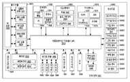
도 17을 참조하여, 다양한 실시예에서의, 네트워크 환경(1700) 내의 전자 장치(1701)가 기재된다. 웨어러블 전자 장치(1701)는 버스(1710), 프로세서(1720), 메모리(1730), 입출력 인터페이스(1750), 디스플레이(1760), 및 통신 인터페이스(1770)를 포함할 수 있다. 어떤 실시예에서는, 전자 장치(1701)는, 구성요소들 중 적어도 하나를 생략하거나 다른 구성요소를 추가적으로 구비할 수 있다.Referring to FIG. 17, in various embodiments, an
버스(1710)는, 예를 들면, 구성요소들(1710-1770)을 서로 연결하고, 구성요소들 간의 통신(예: 제어 메시지 및/또는 데이터)을 전달하는 회로를 포함할 수 있다.
프로세서(1720)는, 중앙처리장치(central processing unit(CPU)), 어플리케이션 프로세서(application processor(AP)), 또는 커뮤니케이션 프로세서(communication processor(CP)) 중 하나 또는 그 이상을 포함할 수 있다. 프로세서(1720)는, 예를 들면, 웨어러블 전자 장치(1701)의 적어도 하나의 다른 구성요소들의 제어 및/또는 통신에 관한 연산이나 데이터 처리를 실행할 수 있다.
메모리(1730)는, 휘발성 및/또는 비휘발성 메모리를 포함할 수 있다. 메모리(1730)는, 예를 들면, 웨어러블 전자 장치(1701)의 적어도 하나의 다른 구성요소에 관계된 명령 또는 데이터를 저장할 수 있다. 한 실시예에 따르면, 메모리(1730)는 소프트웨어 및/또는 프로그램(1740)을 저장할 수 있다. 프로그램(1740)은, 예를 들면, 커널(1741), 미들웨어(1743), 어플리케이션 프로그래밍 인터페이스(application programming interface(API))(1745), 및/또는 어플리케이션 프로그램(또는 "어플리케이션")(1747) 등을 포함할 수 있다. 커널(1741), 미들웨어(143), 또는 API(1745)의 적어도 일부는, 운영 시스템(operating system(OS))으로 지칭될 수 있다.
커널(1741)은, 예를 들면, 다른 프로그램들(예: 미들웨어(1743), API(1745), 또는 어플리케이션 프로그램(1747))에 구현된 동작 또는 기능을 실행하는 데 사용되는 시스템 리소스들(예: 버스(1710), 프로세서(1720), 또는 메모리(1730) 등)을 제어 또는 관리할 수 있다. 또한, 커널(1741)은 미들웨어(1743), API(1745), 또는 어플리케이션 프로그램(1747)에서 웨어러블 전자 장치(1701)의 개별 구성요소에 접근함으로써, 시스템 리소스들을 제어 또는 관리할 수 있는 인터페이스를 제공할 수 있다.The
미들웨어(1743)는, 예를 들면, API(1745) 또는 어플리케이션 프로그램(1747)이 커널(1741)과 통신하여 데이터를 주고받을 수 있도록 중개 역할을 수행할 수 있다.The
또한, 미들웨어(1743)는 어플리케이션 프로그램(1747)으로부터 수신된 하나 이상의 작업 요청들을 우선 순위에 따라 처리할 수 있다. 예를 들면, 미들웨어(1743)는 어플리케이션 프로그램(1747) 중 적어도 하나에 전자 장치(1701)의 시스템 리소스(예: 버스(1710), 프로세서(1720), 또는 메모리(1730) 등)를 사용할 수 있는 우선 순위를 부여할 수 있다. 예컨대, 미들웨어(1743)는 상기 적어도 하나에 부여된 우선 순위에 따라 상기 하나 이상의 작업 요청들을 처리함으로써, 상기 하나 이상의 작업 요청들에 대한 스케쥴링 또는 로드 밸런싱 등을 수행할 수 있다.
API(1745)는, 예를 들면, 어플리케이션(1747)이 커널(1741) 또는 미들웨어(1743)에서 제공되는 기능을 제어하기 위한 인터페이스로, 예를 들면, 파일 제어, 창 제어, 영상 처리, 또는 문자 제어 등을 위한 적어도 하나의 인터페이스 또는 함수(예: 명령어)를 포함할 수 있다.The
입출력 인터페이스(1750)는, 예를 들면, 사용자 또는 다른 외부 기기로부터 입력된 명령 또는 데이터를 전자 장치(1701)의 다른 구성요소(들)에 전달할 수 있는 인터페이스의 역할을 할 수 있다. 또한, 입출력 인터페이스(1750)는 웨어러블 전자 장치(1701)의 다른 구성요소(들)로부터 수신된 명령 또는 데이터를 사용자 또는 다른 외부 기기로 출력할 수 있다.The input /
디스플레이(1760)는, 예를 들면, 액정 디스플레이(liquid crystal display(LCD)), 발광 다이오드(light-emitting diode(LED)) 디스플레이, 유기 발광 다이오드(organic light-emitting diode(OLED)) 디스플레이, 또는 마이크로 전자기계 시스템(microelectromechanical systems(MEMS)) 디스플레이, 또는 전자종이(electronic paper) 디스플레이를 포함할 수 있다. 디스플레이(1760)는, 예를 들면, 사용자에게 각종 콘텐츠(예: 텍스트, 이미지, 비디오, 아이콘, 또는 심볼 등)을 표시할 수 있다. 디스플레이(1760)는, 터치 스크린을 포함할 수 있으며, 예를 들면, 전자 펜 또는 사용자의 신체의 일부를 이용한 터치, 제스쳐, 근접, 또는 호버링 입력을 수신할 수 있다.
통신 인터페이스(1770)는, 예를 들면, 전자 장치(1701)와 외부 장치(예: 제 1 외부 전자 장치(1702), 제 2 외부 전자 장치(1704), 또는 서버(1706)) 간의 통신을 설정할 수 있다. 예를 들면, 통신 인터페이스(1770)는 무선 통신 또는 유선 통신을 통해서 네트워크(1762)에 연결되어 외부 장치(예: 제 2 외부 전자 장치(1704) 또는 서버(1706))와 통신할 수 있다.
무선 통신은, 예를 들면, 셀룰러 통신 프로토콜로서, 예를 들면, LTE(long-term evolution), LTE-A(LTE Advance), CDMA(code division multiple access), WCDMA(wideband CDMA), UMTS(universal mobile telecommunications system), WiBro(Wireless Broadband), 또는 GSM(Global System for Mobile Communications) 등 중 적어도 하나를 사용할 수 있다. 또한, 무선 통신은, 예를 들면, 근거리 통신(1764)을 포함할 수 있다. 근거리 통신(1764)은, 예를 들면, WiFi(wireless fidelity), 블루투스(Bluetooth), NFC(near field communication), 또는 GNSS(global navigation satellite system) 등 중 적어도 하나를 포함할 수 있다. GNSS는 사용 지역 또는 대역폭 등에 따라, 예를 들면, GPS(Global Positioning System), Glonass(Global Navigation Satellite System), Beidou Navigation Satellite System(이하 'Beidou' 또는 Galileo, the European global satellite-based navigation system 중 적어도 하나를 포함할 수 있다. 이하, 본 문서에서는, GPS는 GNSS와 혼용되어 사용(interchangeably used)될 수 있다. 유선 통신은, 예를 들면, USB(universal serial bus), HDMI(high definition multimedia interface), RS-232(recommended standard232), 또는 POTS(plain old telephone service) 등 중 적어도 하나를 포함할 수 있다. 네트워크(1762)는 통신 네트워크(telecommunications network), 예를 들면, 컴퓨터 네트워크(computer network)(예: LAN 또는 WAN), 인터넷, 또는 전화 망(telephone network) 중 적어도 하나를 포함할 수 있다.Wireless communications may include, for example, cellular communication protocols such as long-term evolution (LTE), LTE Advance (LTE), code division multiple access (CDMA), wideband CDMA (WCDMA) mobile telecommunications system, WiBro (Wireless Broadband), or Global System for Mobile Communications (GSM). The wireless communication may also include, for example,
제 1 및 제 2 외부 전자 장치(1702, 1704) 각각은 전자 장치(1701)와 동일한 또는 다른 종류의 장치일 수 있다. 한 실시예에 따르면, 서버(1706)는 하나 또는 그 이상의 서버들의 그룹을 포함할 수 있다. 다양한 실시예에 따르면, 전자 장치(1701)에서 실행되는 동작들의 전부 또는 일부는 다른 하나 또는 복수의 전자 장치(예: 전자 장치(1702,1704), 또는 서버(1706)에서 실행될 수 있다. 한 실시예에 따르면, 전자 장치(1701)가 어떤 기능이나 서비스를 자동으로 또는 요청에 의하여 수행해야 할 경우에, 전자 장치(1701)는 기능 또는 서비스를 자체적으로 실행시키는 대신에 또는 추가적으로, 그와 연관된 적어도 일부 기능을 다른 장치(예: 전자 장치(1702, 1704), 또는 서버(1706))에게 요청할 수 있다. 다른 전자 장치(예: 전자 장치(1702, 1704), 또는 서버(1706))는 요청된 기능 또는 추가 기능을 실행하고, 그 결과를 전자 장치(1701)로 전달할 수 있다. 전자 장치(1701)는 수신된 결과를 그대로 또는 추가적으로 처리하여 요청된 기능이나 서비스를 제공할 수 있다. 이를 위하여, 예를 들면, 클라우드 컴퓨팅, 분산 컴퓨팅, 또는 클라이언트-서버 컴퓨팅 기술이 이용될 수 있다.Each of the first and second external
도 18은 다양한 실시예에 따른 전자 장치의 블록도이다. 전자 장치(201)는, 예를 들면, 도17에 도시된 전자 장치(1701)의 전체 또는 일부를 포함할 수 있다. 전자 장치(1801)는 하나 이상의 프로세서(예: AP(application processor))(1810), 통신 모듈(1820), (가입자 식별 모듈(1824), 메모리(1830), 센서 모듈(1840), 입력 장치(1850), 디스플레이(1860), 인터페이스(1870), 오디오 모듈(1880), 카메라 모듈(1891), 전력 관리 모듈(1895), 배터리(1896), 인디케이터(1897), 및 모터(1898)를 포함할 수 있다.18 is a block diagram of an electronic device according to various embodiments. The electronic device 201 may include all or part of the
프로세서(1810)는, 예를 들면, 운영 체제 또는 응용 프로그램을 구동하여 프로세서(1810)에 연결된 다수의 하드웨어 또는 소프트웨어 구성요소들을 제어할 수 있고, 각종 데이터 처리 및 연산을 수행할 수 있다. 프로세서(1810)는, 예를 들면, SoC(system on chip) 로 구현될 수 있다. 한 실시예에 따르면, 프로세서(1810)는 GPU(graphic processing unit) 및/또는 이미지 신호 프로세서(image signal processor)를 더 포함할 수 있다. 프로세서(1810)는 도 17에 도시된 구성요소들 중 적어도 일부(예: 셀룰러 모듈(1821))를 포함할 수도 있다. 프로세서(1810) 는 다른 구성요소들(예: 비휘발성 메모리) 중 적어도 하나로부터 수신된 명령 또는 데이터를 휘발성 메모리에 로드(load)하여 처리하고, 다양한 데이터를 비휘발성 메모리에 저장(store)할 수 있다.
통신 모듈(1820)은, 도 17의 통신 인터페이스(1770)와 동일 또는 유사한 구성을 가질 수 있다. 통신 모듈(1820)은, 예를 들면, 셀룰러 모듈(221), WiFi 모듈(1823), 블루투스 모듈(1825), GNSS 모듈(1827)(예: GPS 모듈, Glonass 모듈, Beidou 모듈, 또는 Galileo 모듈), NFC 모듈(1828) 및 RF(radio frequency) 모듈(1829)를 포함할 수 있다.The
셀룰러 모듈(1821)은, 예를 들면, 통신망을 통해서 음성 통화, 영상 통화, 문자 서비스, 또는 인터넷 서비스 등을 제공할 수 있다. 한 실시예에 따르면, 셀룰러 모듈(1821)은 가입자 식별 모듈(예: SIM 카드)(1824)을 이용하여 통신 네트워크 내에서 전자 장치(1801)의 구별 및 인증을 수행할 수 있다. 한 실시예에 따르면, 셀룰러 모듈(1821)은 프로세서(210)가 제공할 수 있는 기능 중 적어도 일부 기능을 수행할 수 있다. 한 실시예에 따르면, 셀룰러 모듈(1821)은 커뮤니케이션 프로세서(CP: communication processor)를 포함할 수 있다.The cellular module 1821 may provide voice, video, text, or Internet services, for example, over a communication network. According to one embodiment, cellular module 1821 may utilize a subscriber identity module (e.g., a SIM card) 1824 to perform the identification and authentication of electronic device 1801 within the communication network. According to one embodiment, the cellular module 1821 may perform at least some of the functions that the
WiFi 모듈(1823), 블루투스 모듈(1825), GNSS 모듈(1827) 또는 NFC 모듈(1828) 각각은, 예를 들면, 해당하는 모듈을 통해서 송수신되는 데이터를 처리하기 위한 프로세서를 포함할 수 있다. 어떤 실시예에 따르면, 셀룰러 모듈(1821), WiFi 모듈(1823), 블루투스 모듈(1825), GNSS 모듈(1827) 또는 NFC 모듈(1828) 중 적어도 일부(예: 두 개 이상)는 하나의 integrated chip(IC) 또는 IC 패키지 내에 포함될 수 있다.Each of the
RF 모듈(1829)은, 예를 들면, 통신 신호(예: RF 신호)를 송수신할 수 있다. RF 모듈(1829)은, 예를 들면, 트랜시버(transceiver), PAM(power amp module), 주파수 필터(frequency filter), LNA(low noise amplifier), 또는 안테나 등을 포함할 수 있다. 다른 실시예에 따르면, 셀룰러 모듈(1821), WiFi 모듈(1823), 블루투스 모듈(1825), GNSS 모듈(1827) 또는 NFC 모듈(1828) 중 적어도 하나는 별개의 RF 모듈을 통하여 RF 신호를 송수신할 수 있다.The
가입자 식별 모듈(1824)은, 예를 들면, 가입자 식별 모듈을 포함하는 카드 및/또는 내장 SIM(embedded SIM)을 포함할 수 있으며, 고유한 식별 정보(예: ICCID(integrated circuit card identifier)) 또는 가입자 정보(예: IMSI(international mobile subscriber identity))를 포함할 수 있다.The
메모리(1830)(예: 메모리(1730))는, 예를 들면, 내장 메모리(1832) 또는 외장 메모리(1834)를 포함할 수 있다. 내장 메모리(1832)는, 예를 들면, 휘발성 메모리(예: DRAM(dynamic RAM), SRAM(static RAM), 또는 SDRAM(synchronous dynamic RAM) 등), 비휘발성 메모리(non-volatile Memory)(예: OTPROM(one time programmable ROM), PROM(programmable ROM), EPROM(erasable and programmable ROM), EEPROM(electrically erasable and programmable ROM), mask ROM, flash ROM, 플래시 메모리(예: NAND flash 또는 NOR flash 등), 하드 드라이브, 또는 솔리드 스테이트 드라이브(solid state drive(SSD)) 중 적어도 하나를 포함할 수 있다.The memory 1830 (e.g., memory 1730) may include, for example, an internal memory 1832 or an external memory 1834. The built-in memory 1832 may be a nonvolatile memory such as a volatile memory such as a dynamic RAM (RAM), a static random access memory (SRAM), or a synchronous dynamic RAM (SDRAM) Programmable ROM (EPROM), electrically erasable and programmable ROM (EEPROM), mask ROM, flash ROM, flash memory (e.g., NAND flash or NOR flash) A hard drive, or a solid state drive (SSD).
외장 메모리(1834)는 플래시 드라이브(flash drive), 예를 들면, CF(compact flash), SD(secure digital), Micro-SD(micro secure digital), Mini-SD(mini secure digital), xD(extreme digital), MMC(multi-media card) 또는 메모리 스틱(memory stick) 등을 더 포함할 수 있다. 외장 메모리(1834)는 다양한 인터페이스를 통하여 전자 장치(1801)와 기능적으로 및/또는 물리적으로 연결될 수 있다.The external memory 1834 may be a flash drive such as a compact flash (CF), a secure digital (SD), a micro secure digital (SD), a mini secure digital (SD) digital, a multi-media card (MMC), a memory stick, and the like. The external memory 1834 may be functionally and / or physically connected to the electronic device 1801 via various interfaces.
센서 모듈(1840)은, 예를 들면, 물리량을 계측하거나 전자 장치(1801)의 작동 상태를 감지하여, 계측 또는 감지된 정보를 전기 신호로 변환할 수 있다. 센서 모듈(1840)은, 예를 들면, 제스처 센서(1840A), 자이로 센서(1840B), 기압 센서(1840C), 마그네틱 센서(1840D), 가속도 센서(1840E), 그립 센서(1840F), 근접 센서(1840G), 컬러(color) 센서(1840H)(예: RGB(red, green, blue) 센서), 생체 센서(1840I), 온/습도 센서(1840J), 조도 센서(1840K), 또는 UV(ultra violet) 센서(1840M) 중의 적어도 하나를 포함할 수 있다. 추가적으로 또는 대체적으로(additionally or alternatively), 센서 모듈(1840)은, 예를 들면, 후각 센서(E-nose sensor), EMG 센서(electromyography sensor), EEG 센서(electroencephalogram sensor), ECG 센서(electrocardiogram sensor), IR(infrared) 센서, 홍채 센서 및/또는 지문 센서를 포함할 수 있다. 센서 모듈(1840)은 그 안에 속한 적어도 하나 이상의 센서들을 제어하기 위한 제어 회로를 더 포함할 수 있다. 어떤 실시예에서는, 전자 장치(1801)는 프로세서(1810)의 일부로서 또는 별도로, 센서 모듈(1840)을 제어하도록 구성된 프로세서를 더 포함하여, 프로세서(1810)가 슬립(sleep) 상태에 있는 동안, 센서 모듈(1840)을 제어할 수 있다.The
입력 장치(1850)는, 예를 들면, 터치 패널(touch panel)(1852),(디지털) 펜 센서(pen sensor)(1854), 키(key)(1856), 또는 초음파(ultrasonic) 입력 장치(1858)를 포함할 수 있다. 터치 패널(1852)은, 예를 들면, 정전식, 감압식, 적외선 방식, 또는 초음파 방식 중 적어도 하나의 방식을 사용할 수 있다. 또한, 터치 패널(1852)은 제어 회로를 더 포함할 수도 있다. 터치 패널(1852)은 택타일 레이어(tactile layer)를 더 포함하여, 사용자에게 촉각 반응을 제공할 수 있다.The
(디지털) 펜 센서(1854)는, 예를 들면, 터치 패널의 일부이거나, 별도의 인식용 쉬트(sheet)를 포함할 수 있다. 키(1856)는, 예를 들면, 물리적인 버튼, 광학식 키, 또는 키패드를 포함할 수 있다. 초음파 입력 장치(1858)는 마이크(예: 마이크(1888))를 통해, 입력 도구에서 발생된 초음파를 감지하여, 상기 감지된 초음파에 대응하는 데이터를 확인할 수 있다.(Digital)
디스플레이(1860)(예: 디스플레이(1760))는 패널(1862), 홀로그램 장치(1864), 또는 프로젝터(1866)를 포함할 수 있다. 패널(1862)은, 도 17의 디스플레이(1760)와 동일 또는 유사한 구성을 포함할 수 있다. 패널(1862)은, 예를 들면, 유연하게(flexible), 투명하게(transparent), 또는 착용할 수 있게(wearable) 구현될 수 있다. 패널(1862)은 터치 패널(1852)과 하나의 모듈로 구성될 수도 있다. 홀로그램 장치(1864)는 빛의 간섭을 이용하여 입체 영상을 허공에 보여줄 수 있다. 프로젝터(1866)는 스크린에 빛을 투사하여 영상을 표시할 수 있다. 스크린은, 예를 들면, 전자 장치(1801)의 내부 또는 외부에 위치할 수 있다. 한 실시예에 따르면, 디스플레이(1860)는 패널(1862), 홀로그램 장치(1864), 또는 프로젝터(1866)를 제어하기 위한 제어 회로를 더 포함할 수 있다.Display 1860 (e.g., display 1760) may include a panel 1862, a hologram device 1864, or a projector 1866. Panel 1862 may include the same or similar configuration as
인터페이스(1870)는, 예를 들면, HDMI(high-definition multimedia interface)(1872), USB(universal serial bus)(1874), 광 인터페이스(optical interface)(1876), 또는 D-sub(D-subminiature)(1878)를 포함할 수 있다. 인터페이스(1870)는, 예를 들면, 도 17에 도시된 통신 인터페이스(1770)에 포함될 수 있다. 추가적으로 또는 대체적으로(additionally and alternatively), 인터페이스(1870)는, 예를 들면, MHL(mobile high-definition link) 인터페이스, SD(secure digital) 카드/MMC(multi-media card) 인터페이스, 또는 IrDA(infrared data association) 규격 인터페이스를 포함할 수 있다.The
오디오 모듈(1880)은, 예를 들면, 소리(sound)와 전기 신호를 쌍방향으로 변환시킬 수 있다. 오디오 모듈(1880)의 적어도 일부 구성요소는, 예를 들면, 도 17 에 도시된 입출력 인터페이스(1745)에 포함될 수 있다. 오디오 모듈(1880)은, 예를 들면, 스피커(1882), 리시버(1884), 이어폰(1886), 또는 마이크(1888) 등을 통해 입력 또는 출력되는 소리 정보를 처리할 수 있다.Audio module 1880 can, for example, convert sound and electrical signals in both directions. At least some of the components of the audio module 1880 may be included, for example, in the input /
카메라 모듈(1891)은, 예를 들면, 정지 영상 및 동영상을 촬영할 수 있는 장치로서, 한 실시예에 따르면, 하나 이상의 이미지 센서(예: 전면 센서 또는 후면 센서), 렌즈, ISP(image signal processor), 또는 플래시(flash)(예: LED 또는 xenon lamp 등)를 포함할 수 있다.The
전력 관리 모듈(1895)은, 예를 들면, 전자 장치(1801)의 전력을 관리할 수 있다. 한 실시예에 따르면, 전력 관리 모듈(1895)은 PMIC(power management integrated circuit), 충전 IC(charger integrated circuit), 또는 배터리 또는 연료 게이지(battery or fuel gauge)를 포함할 수 있다. PMIC는, 유선 및/또는 무선 충전 방식을 가질 수 있다. 무선 충전 방식은, 예를 들면, 자기공명 방식, 자기유도 방식 또는 전자기파 방식 등을 포함하며, 무선 충전을 위한 부가적인 회로, 예를 들면, 코일 루프, 공진 회로, 또는 정류기 등을 더 포함할 수 있다. 배터리 게이지는, 예를 들면, 배터리(1896)의 잔량, 충전 중 전압, 전류, 또는 온도를 측정할 수 있다. 배터리(1896)는, 예를 들면, 충전식 전지(rechargeable battery) 및/또는 태양 전지(solar battery)를 포함할 수 있다.The power management module 1895 can manage the power of the electronic device 1801, for example. According to one embodiment, the power management module 1895 may include a power management integrated circuit (PMIC), a charger integrated circuit ("IC"), or a battery or fuel gauge. The PMIC may have a wired and / or wireless charging scheme. The wireless charging scheme may include, for example, a magnetic resonance scheme, a magnetic induction scheme, or an electromagnetic wave scheme, and may further include an additional circuit for wireless charging, for example, a coil loop, a resonant circuit, have. The battery gauge can measure, for example, the remaining amount of the battery 1896, the voltage during charging, the current, or the temperature. The battery 1896 may include, for example, a rechargeable battery and / or a solar battery.
인디케이터(1897)는 전자 장치(1801) 또는 그 일부(예: 프로세서(1810))의 특정 상태, 예를 들면, 부팅 상태, 메시지 상태 또는 충전 상태 등을 표시할 수 있다. 모터(1898)는 전기적 신호를 기계적 진동으로 변환할 수 있고, 진동(vibration), 또는 햅틱(haptic) 효과 등을 발생시킬 수 있다. 도시되지는 않았으나, 전자 장치(1801)는 모바일 TV 지원을 위한 처리 장치(예: GPU)를 포함할 수 있다. 모바일 TV 지원을 위한 처리 장치는, 예를 들면, DMB(digital multimedia broadcasting), DVB(digital video broadcasting), 또는 미디어플로(mediaFloTM) 등의 규격에 따른 미디어 데이터를 처리할 수 있다.The
본 문서에서 기술된 구성요소들 각각은 하나 또는 그 이상의 부품(component)으로 구성될 수 있으며, 해당 구성요소의 명칭은 전자 장치의 종류에 따라서 달라질 수 있다. 다양한 실시예에서, 전자 장치는 본 문서에서 기술된 구성요소 중 적어도 하나를 포함하여 구성될 수 있으며, 일부 구성요소가 생략되거나 또는 추가적인 다른 구성요소를 더 포함할 수 있다. 또한, 다양한 실시예에 따른 전자 장치의 구성요소들 중 일부가 결합되어 하나의 개체(entity)로 구성됨으로써, 결합되기 이전의 해당 구성요소들의 기능을 동일하게 수행할 수 있다.Each of the components described in this document may be composed of one or more components, and the name of the component may be changed according to the type of the electronic device. In various embodiments, the electronic device may comprise at least one of the components described herein, some components may be omitted, or may further include additional other components. In addition, some of the components of the electronic device according to various embodiments may be combined into one entity, so that the functions of the components before being combined can be performed in the same manner.
본 문서에서 사용된 용어 "모듈"은 예를 들면, 하드웨어, 소프트웨어 또는 펌웨어 (firmware) 중 하나 또는 둘 이상의 조합을 포함하는 단위 (unit)를 의미할 수 있다. "모듈"은, 예를 들면, 유닛 (unit), 로직 (logic), 논리 블록 (logical block), 부품 (component), 또는 회로 (circuit) 등의 용어와 바꾸어 사용 (interchangeably use)될 수 있다. "모듈"은, 일체로 구성된 부품의 최소 단위 또는 그 일부가 될 수 있다. "모듈"은 하나 또는 그 이상의 기능을 수행하는 최소 단위 또는 그 일부가 될 수도 있다. 은 기계적으로 또는 전자적으로 구현될 수 있다. 예를 들면, "모듈"은, 알려졌거나 앞으로 개발될, 어떤 동작들을 수행하는 ASIC(application-specific integrated circuit) 칩, FPGAs(field-programmable gate arrays) 또는 프로그램 가능 논리 장치(programmable-logic device) 중 적어도 하나를 포함할 수 있다.As used in this document, the term "module" may refer to a unit comprising, for example, one or more combinations of hardware, software or firmware. A "module" may be interchangeably used with terms such as, for example, unit, logic, logical block, component, or circuit. A "module" may be a minimum unit or a portion of an integrally constructed component. A "module" may be a minimum unit or a portion thereof that performs one or more functions. May be implemented mechanically or electronically. For example, a "module" may be an application-specific integrated circuit (ASIC) chip, field-programmable gate arrays (FPGAs) or programmable-logic devices And may include at least one.
다양한 실시예에 따르면, 본 개시에 따른 장치(예: 모듈들 또는 그 기능들) 또는 방법(예: 동작들)의 적어도 일부는, 예컨대, 프로그래밍 모듈의 형태로 컴퓨터로 읽을 수 있는 저장매체(computer-readable storage media)에 저장된 명령어로 구현될 수 있다. 상기 명령어는, 하나 이상의 프로세서 (예: 상기 프로세서 1810)에 의해 실행될 경우, 상기 하나 이상의 프로세서가 상기 명령어에 해당하는 기능을 수행할 수 있다. 컴퓨터로 읽을 수 있는 저장매체는, 예를 들면, 상기 메모리 1820가 될 수 있다. 상기 프로그래밍 모듈의 적어도 일부는, 예를 들면, 프로세서에 의해 구현(implement)(예:실행)될 수 있다. 상기 프로그래밍 모듈의 적어도 일부는 하나 이상의 기능을 수행하기 위한, 예를 들면, 모듈, 프로그램, 루틴, 명령어 세트(sets of instructions) 또는 프로세스 등을 포함할 수 있다.According to various embodiments, at least some of the devices (e.g., modules or functions thereof) or methods (e.g., operations) according to the present disclosure may be stored in a computer readable storage medium -readable storage media). The instructions, when executed by one or more processors (e.g., the processor 1810), may cause the one or more processors to perform functions corresponding to the instructions. The computer readable storage medium may be, for example, the
상기 컴퓨터로 판독 가능한 기록 매체에는 하드디스크, 플로피디스크 및 자기 테이프와 같은 마그네틱 매체(Magnetic Media)와, CD-ROM(Compact Disc Read Only Memory), DVD(Digital Versatile Disc)와 같은 광기록 매체(Optical Media)와, 플롭티컬 디스크(Floptical Disk)와 같은 자기-광 매체(Magneto-Optical Media)와, 그리고 ROM(Read Only Memory), RAM(Random Access Memory), 플래시 메모리 등과 같은 프로그램 명령(예: 프로그래밍 모듈)을 저장하고 수행하도록 특별히 구성된 하드웨어 장치가 포함될 수 있다. 또한, 프로그램 명령에는 컴파일러에 의해 만들어지는 것과 같은 기계어 코드뿐만 아니라 인터프리터 등을 사용해서 컴퓨터에 의해서 실행될 수 있는 고급 언어 코드를 포함할 수 있다. 상술한 하드웨어 장치는 본 개시의 동작을 수행하기 위해 하나 이상의 소프트웨어 모듈로서 작동하도록 구성될 수 있으며, 그 역도 마찬가지다.The computer-readable recording medium includes a magnetic medium such as a hard disk, a floppy disk and a magnetic tape, an optical recording medium such as a CD-ROM (Compact Disc Read Only Memory), a DVD (Digital Versatile Disc) A magneto-optical medium such as a floppy disk, and a program command such as a read only memory (ROM), a random access memory (RAM), a flash memory, Module) that is configured to store and perform the functions described herein. The program instructions may also include machine language code such as those generated by a compiler, as well as high-level language code that may be executed by a computer using an interpreter or the like. The hardware devices described above may be configured to operate as one or more software modules to perform the operations of this disclosure, and vice versa.
본 개시에 따른 모듈 또는 프로그래밍 모듈은 전술한 구성요소들 중 적어도 하나 이상을 포함하거나, 일부가 생략되거나, 또는 추가적인 다른 구성요소를 더 포함할 수 있다. 본 개시에 따른 모듈, 프로그래밍 모듈 또는 다른 구성요소에 의해 수행되는 동작들은 순차적, 병렬적, 반복적 또는 휴리스틱(heuristic)한 방법으로 실행될 수 있다. 또한, 일부 동작은 다른 순서로 실행되거나, 생략되거나, 또는 다른 동작이 추가될 수 있다.A module or programming module according to the present disclosure may include at least one or more of the elements described above, some of which may be omitted, or may further include other additional elements. Operations performed by modules, programming modules, or other components in accordance with the present disclosure may be performed in a sequential, parallel, iterative, or heuristic manner. Also, some operations may be performed in a different order, omitted, or other operations may be added.
그리고, 본 명세서와 도면에 개시된 본 개시의 다양한 실시예들은 본 개시의 기술 내용을 쉽게 설명하고 본 개시의 이해를 돕기 위해 특정 예를 제시한 것일 뿐이며, 본 개시의 범위를 한정하고자 하는 것은 아니다. 따라서 본 개시의 범위는 여기에 개시된 실시 예들 이외에도 본 개시의 기술적 사상을 바탕으로 도출되는 모든 변경 또는 변형된 형태가 본 개시의 범위에 포함되는 것으로 해석되어야 한다.It is to be understood that the various embodiments of the present disclosure disclosed in this specification and the drawings are only illustrative of specific examples in order to facilitate describing the subject matter of the disclosure and to facilitate understanding of the disclosure, and are not intended to limit the scope of the disclosure. Accordingly, the scope of the present disclosure should be construed as being included within the scope of the present disclosure in addition to the embodiments disclosed herein, all changes or modifications derived from the technical idea of the present disclosure.
Claims (20)
Translated fromKorean제1방향으로 향하는 제1면, 상기 제1방향에 반대인 제2방향으로 향하는 제2면, 및 상기 제 1 면 및 제 2 면 사이의 공간을 둘러싸는 측면을 포함하는 하우징;
상기 하우징의 제1면의 적어도 일부를 형성하는 투명 기판;
상기 하우징의 공간 내에 배치되고, 상기 투명 기판의 적어도 일부를 통해 노출된 디스플레이;
상기 투명 기판 및 상기 디스플레이 사이에 적어도 일부 배치되고, 물리적으로 이동 가능한 기계적 시계 구조(mechanical watch structure);
상기 디스플레이 및 상기 시계 구조에 전기적으로 연결된 프로세서; 및
상기 프로세서와 전기적으로 연결된 메모리를 포함하며,
상기 메모리는, 실행시에, 상기 프로세서가, 상기 디스플레이 및 상기 시계 구조를 제어하도록 하는 인스트럭션들을 저장하는 장치.In an electronic device,
A housing including a first surface facing in a first direction, a second surface facing in a second direction opposite to the first direction, and a side surface surrounding a space between the first surface and the second surface;
A transparent substrate defining at least a portion of a first side of the housing;
A display disposed within the space of the housing and exposed through at least a portion of the transparent substrate;
A mechanical watch structure disposed at least partially between the transparent substrate and the display and being physically movable;
A processor electrically connected to the display and the watch structure; And
And a memory electrically coupled to the processor,
Wherein the memory stores instructions that, when executed, cause the processor to control the display and the clock structure.
시(hour)를 지시하도록 이동가능한 제1부재; 및
분(minute)을 지시하도록 이동가능한 제2부재를 포함하는 장치.The method of claim 1,
A first member movable to indicate an hour; And
And a second member movable to indicate a minute.
상기 하우징의 측면의 내면의 일부와 접촉하며 상기 내면을 따라 이동 가능하도록 구성된 제1단면; 및
상기 제1단면의 반대편의 제2단면을 포함하고,
상기 제2부재는,
상기 하우징의 측면의 내면의 다른 일부와 접촉하며 상기 제1부재와 독립적으로 상기 내면을 따라 이동 가능하도록 구성된 제1단면; 및
상기 제1단면의 반대편의 제2단면을 포함하는 장치.3. The apparatus according to claim 2,
A first end adapted to contact a portion of an inner surface of a side surface of the housing and to be movable along the inner surface; And
A second cross-section opposite the first cross-section,
The second member
A first end that is in contact with another portion of the inner surface of the side surface of the housing and is configured to be movable along the inner surface independently of the first member; And
And a second cross-section opposite the first cross-section.
상기 디스플레이가 활성화되었는지 여부를 판단하고,
상기 판단에 따라,
상기 디스플레이가 활성화된 경우, 상기 제1부재 및/또는 상기 제2부재를 제1형상으로 고정시켜서 상기 디스플레이를 가리지 않도록 하고,
상기 디스플레이가 비활성화된 경우, 상기 제1부재 및/또는 상기 제2부재를 제2형상으로 고정시켜서 시각을 지시하는 장치.2. The apparatus of claim 1, wherein the instructions cause the processor to:
Determining whether the display is activated,
According to the determination,
Fixing the first member and / or the second member in a first shape so as not to cover the display when the display is activated,
And fixes said first member and / or said second member in a second shape to indicate time when said display is inactive.
상기 디스플레이가 활성화된 경우, 상기 제1부재의 제2단부 및 상기 제2부재의 제2단부가 상기 디스플레이의 중심 부분에서 서로 인접하도록, 상기 제1부재 및/또는 상기 제2부재를 상기 제1형상으로 고정시켜서 상기 디스플레이를 가리지 않도록 하고,
상기 디스플레이가 비활성화된 경우, 상기 제1부재의 제2단부 및 상기 제2부재의 제2단부가 상기 하우징의 측면의 내면에 접촉하도록, 상기 제 1부재 및/또는 상기 제2부재를 상기 제2형상으로 고정시켜서 시각을 지시하는 장치.5. The apparatus of claim 4, wherein the instructions cause the processor to:
The first member and / or the second member are arranged in the first and / or second member so that the second end of the first member and the second end of the second member are adjacent to each other at a central portion of the display, So as not to cover the display,
Wherein the first member and / or the second member are arranged in the second direction so that the second end of the first member and the second end of the second member contact the inner surface of the side surface of the housing when the display is inactivated, And fixes it in a shape to indicate the time.
상기 제1부재의 제2단면 또는 상기 제2부재의 제2단면을 상기 하우징의 측면의 내면에 고정시키고, 상기 내면을 따라 이동 가능하도록 구성된 고정 부재를 더 포함하는 장치.The electronic device according to claim 1,
And a fixing member configured to fix a second end face of the first member or a second end face of the second member to an inner face of the side face of the housing and to be movable along the inner face.
제1방향으로 향하는 제1면, 상기 제1방향에 반대인 제2방향으로 향하는 제2면, 및 상기 제1면 및 제2면 사이의 공간을 둘러싸는 측면을 포함하는 하우징;
상기 하우징의 제 1 면의 적어도 일부를 형성하는 투명 기판;
상기 하우징의 공간 내에 배치되고, 상기 투명 기판의 적어도 일부를 통해 노출된 디스플레이;
상기 디스플레이의 둘레를 따라 적어도 하나의 폐루프(closed loop)를 형성하는 적어도 하나의 물리적 경로; 및
상기 적어도 하나의 물리적 경로를 따라 상기 제1방향 및 제2방향에 실질적으로 수직인 제3방향으로 이동 가능하도록 배치되고, 시각을 표시하도록 구성된 적어도 하나의 구형 구조를 포함하는 장치.In an electronic device,
A housing including a first surface facing in a first direction, a second surface facing in a second direction opposite to the first direction, and a side surface surrounding a space between the first surface and the second surface;
A transparent substrate defining at least a portion of a first side of the housing;
A display disposed within the space of the housing and exposed through at least a portion of the transparent substrate;
At least one physical path forming at least one closed loop along the periphery of the display; And
And at least one spherical structure arranged to be movable in a third direction substantially perpendicular to the first and second directions along the at least one physical path and configured to display time.
상기 하우징의 공간 내에서 상기 물리적 경로를 따라 이동 가능하도록 배치되고, 상기 적어도 하나의 구형 구조를 상기 제2방향으로 끌어당기도록 구성된 적어도 하나의 전자석(electromagnet)을 더 포함하는 장치.12. The electronic device according to claim 11,
And at least one electromagnet configured to be movable along the physical path in the space of the housing and configured to draw the at least one spherical structure in the second direction.
상기 디스플레이 및 상기 적어도 하나의 전자석과 전기적으로 연결된 프로세서; 및
상기 프로세서와 전기적으로 연결된 메모리를 포함하며,
상기 메모리는, 실행시에, 상기 프로세서가, 상기 전자장치에서 실행되는 적어도 하나의 액션에 기초하여, 상기 적어도 하나의 물리적 경로를 따라 상기 적어도 하나의 전자석을 이동시키도록 하는 인스트럭션들을 저장하는 장치.13. The electronic device according to claim 12,
A processor electrically coupled to the display and the at least one electromagnet; And
And a memory electrically coupled to the processor,
Wherein the memory stores instructions that, when executed, cause the processor to move the at least one electromagnet along the at least one physical path based on at least one action performed in the electronic device.
상기 디스플레이의 둘레를 따라 폐루프를 형성하는 제1물리적 경로; 및
상기 제1물리적 경로로부터 상기 둘레의 바깥쪽으로 연장된 제2물리적 경로를 포함하고,
상기 적어도 하나의 구형 구조는,
상기 제1물리적 경로를 따라 이동 가능하도록 배치된 제1구형 구조; 및
상기 제2물리적 경로를 따라 이동 가능하도록 배치된 제2구형 구조를 포함하고,
상기 적어도 하나의 전자석은,
상기 제1물리적 경로를 따라 이동 가능하도록 배치된 제1전자석; 및
상기 제2물리적 경로를 따라 이동 가능하도록 배치된 제2전자석을 포함하는 장치.14. The method of claim 13, wherein the at least one physical path comprises:
A first physical path forming a closed loop along the periphery of the display; And
And a second physical path extending from the first physical path outwardly of the perimeter,
Wherein the at least one spherical structure comprises:
A first spherical structure disposed to be movable along the first physical path; And
And a second spherical structure disposed to be movable along the second physical path,
Wherein the at least one electromagnet comprises:
A first electromagnet disposed to be movable along the first physical path; And
And a second electromagnet arranged to be movable along the second physical path.
상기 선택된 시각의 시(hour)에 대응하는 상기 제1물리적 경로 상의 제1위치에 인접하도록 상기 제1전자석을 이동시키고,
상기 선택된 시각의 분(minute)에 대응하는 상기 제2물리적 경로 상의 제2위치에 인접하도록 상기 제2전자석을 이동시키도록 구성된 장치.15. The computer readable medium of claim 14, wherein the instructions cause the processor to:
Moving the first electromagnet such that the first electromagnet is adjacent to a first position on the first physical path corresponding to an hour of the selected time,
And move the second electromagnet to be adjacent to a second position on the second physical path corresponding to a minute of the selected time.
상기 디스플레이의 적어도 일부에, 상기 전자장치의 사용자가 이동할 경로를 포함하도록 구성된 지도를 표시하고,
상기 사용자가 상기 경로를 따라 이동할 방향에 대응하는 상기 제 1 물리적 경로 상의 제 1 위치에 인접하도록 상기 제 1 전자석을 이동시키고,
북쪽 방향에 대응하는 상기 제 2 물리적 경로 상의 제 2 위치에 인접하도록 상기 제 2 전자석을 이동시키도록 구성된 장치.16. The apparatus of claim 15, wherein the instructions cause the processor to:
Displaying at least a portion of the display a map configured to include a path through which a user of the electronic device will travel,
Moving the first electromagnet such that the first electromagnet is adjacent to a first position on the first physical path corresponding to a direction in which the user moves along the path,
And to move the second electromagnet to be adjacent to a second position on the second physical path corresponding to the north direction.
본체;
상기 본체 전면에 배치된 디스플레이 영역;
상기 디스플레이 영역을 감싸는 베젤 영역;
상기 디스플레이 오프 시에 디스플레이 영역에 배치되어 시간을 나타내고, 상기 디스플레이 온 시에 베젤 영역에 배치되어 숨겨지는 시계 구조물; 및
상기 베젤 영역에 배치되어, 상기 시계 구조물을 베젤 영역으로 이동하게 하는 힘을 제공하는 구동부를 포함하는 장치.In a wearable device,
main body;
A display area disposed on the front surface of the main body;
A bezel area surrounding the display area;
A clock structure disposed in the display area when the display is turned off to indicate time, and hidden in the bezel area when the display is turned on; And
And a driver disposed in the bezel region for providing a force to move the watch structure to a bezel region.
회전가능하게 배치되는 제1레일;
상기 제1레일을 따라 이동하여 시를 나타내는 시침;
상기 제1레일 상에 배치되되, 상기 시침과 연결되어, 상기 시침의 이동 제공하는 제1구동부;
상기 제1레일과 중첩하게 배치되되, 동축으로 회전가능하게 배치되는 제2레일;
상기 제2레일을 따라 이동하여 분을 나타내는 분침; 및
상기 제2레일 상에 배치되되, 상기 분침과 연결되어, 상기 시침의 이동 제공하는 제2구동부를 포함하는 장치.18. The system of claim 17,
A first rail rotatably disposed;
An hour hand moving along the first rail to indicate time;
A first driver disposed on the first rail and connected to the hour hand to provide movement of the hour hand;
A second rail disposed over the first rail and coaxially rotatably disposed thereon;
A minute hand moving along the second rail to indicate minute; And
And a second driver disposed on the second rail and connected to the minute hand to provide movement of the hour hand.
전면을 가지는 본체;
상기 전면에 배치된 디스플레이 영역;
상기 전면에 상기 디스플레이 영역을 감싸게 주변에 배치된 비스플레이 영역;
상기 비디스플레이 영역에 시간을 나타내는 시계 구조물;
상기 디스플레이 영역 하측에 배치되어 시계 구조물과 연결되고, 상기 시계 구조물을 디스플레이 영역 하측으로 숨겨지게 배치하는 구동부를 포함하는 장치.In a wearable device,
A body having a front surface;
A display area disposed on the front surface;
A visble area disposed around the display area to surround the display area;
A clock structure representing time in the non-display area;
And a driving unit disposed below the display area and connected to the timepiece structure and configured to hide the timepiece structure below the display area.
본체;
상기 본체 전면에 배치된 디스플레이 영역;
상기 디스플레이 영역을 감싸는 제1베젤 영역;
상기 제1베젤 영역을 감싸는 제2베젤 영역;
상기 제1베젤 영역에 수용되어, 시를 나타내는 볼타입 제1오브젝트;
상기 제2베젤 영역에 수용되어, 분을 나타내는 볼타입 제2오브젝트;
상기 본체 내에 실장되어, 상기 제1베젤 영역의 길이방향을 따라서 상기 제1오브젝트를 이동시키는 힘을 제공하는 제1전자석; 및
상기 본체 내에 실장되어, 상기 제2베젤 영역의 길이방향을 따라서 상기 제2오브젝트를 이동시키는 힘을 제공하는 제2전자석을 포함하는 장치.In a wearable device,
main body;
A display area disposed on the front surface of the main body;
A first bezel area surrounding the display area;
A second bezel region surrounding the first bezel region;
A first ball-type object received in the first bezel region, the ball-type first object representing a poem;
A second ball-type object received in the second bezel region and representing a minute;
A first electromagnet mounted in the body to provide a force to move the first object along a longitudinal direction of the first bezel region; And
And a second electromagnet mounted in the body to provide a force to move the second object along a longitudinal direction of the second bezel region.
Priority Applications (2)
| Application Number | Priority Date | Filing Date | Title |
|---|---|---|---|
| KR1020150174964AKR102535081B1 (en) | 2015-12-09 | 2015-12-09 | Watch-type wearable device |
| US15/365,054US10222750B2 (en) | 2015-12-09 | 2016-11-30 | Watch-type wearable device |
Applications Claiming Priority (1)
| Application Number | Priority Date | Filing Date | Title |
|---|---|---|---|
| KR1020150174964AKR102535081B1 (en) | 2015-12-09 | 2015-12-09 | Watch-type wearable device |
Publications (2)
| Publication Number | Publication Date |
|---|---|
| KR20170068123Atrue KR20170068123A (en) | 2017-06-19 |
| KR102535081B1 KR102535081B1 (en) | 2023-05-22 |
Family
ID=59019730
Family Applications (1)
| Application Number | Title | Priority Date | Filing Date |
|---|---|---|---|
| KR1020150174964AActiveKR102535081B1 (en) | 2015-12-09 | 2015-12-09 | Watch-type wearable device |
Country Status (2)
| Country | Link |
|---|---|
| US (1) | US10222750B2 (en) |
| KR (1) | KR102535081B1 (en) |
Cited By (1)
| Publication number | Priority date | Publication date | Assignee | Title |
|---|---|---|---|---|
| CN113126468A (en)* | 2019-12-31 | 2021-07-16 | 伊塔瑞士钟表制造股份有限公司 | Display mechanism for a watch |
Families Citing this family (128)
| Publication number | Priority date | Publication date | Assignee | Title |
|---|---|---|---|---|
| US11871901B2 (en) | 2012-05-20 | 2024-01-16 | Cilag Gmbh International | Method for situational awareness for surgical network or surgical network connected device capable of adjusting function based on a sensed situation or usage |
| US11504192B2 (en) | 2014-10-30 | 2022-11-22 | Cilag Gmbh International | Method of hub communication with surgical instrument systems |
| US9703268B2 (en)* | 2015-09-11 | 2017-07-11 | Lenovo (Singapore) Pte. Ltd. | Gauge opacity control |
| KR102256052B1 (en)* | 2015-12-18 | 2021-05-25 | 삼성전자주식회사 | A wearable electronic device and an operating method thereof |
| US10025399B2 (en)* | 2016-03-16 | 2018-07-17 | Lg Electronics Inc. | Watch type mobile terminal and method for controlling the same |
| CN107203261B (en)* | 2016-03-16 | 2022-05-24 | Lg电子株式会社 | Watch type mobile terminal and control method thereof |
| EP3400580B1 (en)* | 2016-05-17 | 2022-08-31 | Samsung Electronics Co., Ltd. | Method and apparatus for facilitating interaction with virtual reality equipment |
| KR102355149B1 (en)* | 2017-04-25 | 2022-01-25 | 삼성전자주식회사 | Electronic device comprising detachable input device |
| US11311342B2 (en) | 2017-10-30 | 2022-04-26 | Cilag Gmbh International | Method for communicating with surgical instrument systems |
| US11229436B2 (en) | 2017-10-30 | 2022-01-25 | Cilag Gmbh International | Surgical system comprising a surgical tool and a surgical hub |
| US11564756B2 (en) | 2017-10-30 | 2023-01-31 | Cilag Gmbh International | Method of hub communication with surgical instrument systems |
| US11317919B2 (en) | 2017-10-30 | 2022-05-03 | Cilag Gmbh International | Clip applier comprising a clip crimping system |
| US11510741B2 (en) | 2017-10-30 | 2022-11-29 | Cilag Gmbh International | Method for producing a surgical instrument comprising a smart electrical system |
| US11911045B2 (en) | 2017-10-30 | 2024-02-27 | Cllag GmbH International | Method for operating a powered articulating multi-clip applier |
| US11291510B2 (en) | 2017-10-30 | 2022-04-05 | Cilag Gmbh International | Method of hub communication with surgical instrument systems |
| US11026687B2 (en) | 2017-10-30 | 2021-06-08 | Cilag Gmbh International | Clip applier comprising clip advancing systems |
| US11801098B2 (en) | 2017-10-30 | 2023-10-31 | Cilag Gmbh International | Method of hub communication with surgical instrument systems |
| US11925373B2 (en) | 2017-10-30 | 2024-03-12 | Cilag Gmbh International | Surgical suturing instrument comprising a non-circular needle |
| US11446052B2 (en) | 2017-12-28 | 2022-09-20 | Cilag Gmbh International | Variation of radio frequency and ultrasonic power level in cooperation with varying clamp arm pressure to achieve predefined heat flux or power applied to tissue |
| US11253315B2 (en) | 2017-12-28 | 2022-02-22 | Cilag Gmbh International | Increasing radio frequency to create pad-less monopolar loop |
| US11744604B2 (en) | 2017-12-28 | 2023-09-05 | Cilag Gmbh International | Surgical instrument with a hardware-only control circuit |
| US11389164B2 (en) | 2017-12-28 | 2022-07-19 | Cilag Gmbh International | Method of using reinforced flexible circuits with multiple sensors to optimize performance of radio frequency devices |
| US11559308B2 (en) | 2017-12-28 | 2023-01-24 | Cilag Gmbh International | Method for smart energy device infrastructure |
| US11026751B2 (en) | 2017-12-28 | 2021-06-08 | Cilag Gmbh International | Display of alignment of staple cartridge to prior linear staple line |
| US10918310B2 (en) | 2018-01-03 | 2021-02-16 | Biosense Webster (Israel) Ltd. | Fast anatomical mapping (FAM) using volume filling |
| US11013563B2 (en) | 2017-12-28 | 2021-05-25 | Ethicon Llc | Drive arrangements for robot-assisted surgical platforms |
| US11308075B2 (en)* | 2017-12-28 | 2022-04-19 | Cilag Gmbh International | Surgical network, instrument, and cloud responses based on validation of received dataset and authentication of its source and integrity |
| US11273001B2 (en) | 2017-12-28 | 2022-03-15 | Cilag Gmbh International | Surgical hub and modular device response adjustment based on situational awareness |
| US11304763B2 (en) | 2017-12-28 | 2022-04-19 | Cilag Gmbh International | Image capturing of the areas outside the abdomen to improve placement and control of a surgical device in use |
| US11633237B2 (en) | 2017-12-28 | 2023-04-25 | Cilag Gmbh International | Usage and technique analysis of surgeon / staff performance against a baseline to optimize device utilization and performance for both current and future procedures |
| US11179175B2 (en) | 2017-12-28 | 2021-11-23 | Cilag Gmbh International | Controlling an ultrasonic surgical instrument according to tissue location |
| US11786245B2 (en) | 2017-12-28 | 2023-10-17 | Cilag Gmbh International | Surgical systems with prioritized data transmission capabilities |
| US20190201142A1 (en) | 2017-12-28 | 2019-07-04 | Ethicon Llc | Automatic tool adjustments for robot-assisted surgical platforms |
| US11696760B2 (en) | 2017-12-28 | 2023-07-11 | Cilag Gmbh International | Safety systems for smart powered surgical stapling |
| US11284936B2 (en) | 2017-12-28 | 2022-03-29 | Cilag Gmbh International | Surgical instrument having a flexible electrode |
| US11464535B2 (en) | 2017-12-28 | 2022-10-11 | Cilag Gmbh International | Detection of end effector emersion in liquid |
| US20190201090A1 (en) | 2017-12-28 | 2019-07-04 | Ethicon Llc | Capacitive coupled return path pad with separable array elements |
| US11234756B2 (en) | 2017-12-28 | 2022-02-01 | Cilag Gmbh International | Powered surgical tool with predefined adjustable control algorithm for controlling end effector parameter |
| US11202570B2 (en) | 2017-12-28 | 2021-12-21 | Cilag Gmbh International | Communication hub and storage device for storing parameters and status of a surgical device to be shared with cloud based analytics systems |
| US11056244B2 (en) | 2017-12-28 | 2021-07-06 | Cilag Gmbh International | Automated data scaling, alignment, and organizing based on predefined parameters within surgical networks |
| US11076921B2 (en) | 2017-12-28 | 2021-08-03 | Cilag Gmbh International | Adaptive control program updates for surgical hubs |
| US11659023B2 (en) | 2017-12-28 | 2023-05-23 | Cilag Gmbh International | Method of hub communication |
| US10892995B2 (en) | 2017-12-28 | 2021-01-12 | Ethicon Llc | Surgical network determination of prioritization of communication, interaction, or processing based on system or device needs |
| US11571234B2 (en) | 2017-12-28 | 2023-02-07 | Cilag Gmbh International | Temperature control of ultrasonic end effector and control system therefor |
| US11291495B2 (en) | 2017-12-28 | 2022-04-05 | Cilag Gmbh International | Interruption of energy due to inadvertent capacitive coupling |
| US11786251B2 (en) | 2017-12-28 | 2023-10-17 | Cilag Gmbh International | Method for adaptive control schemes for surgical network control and interaction |
| US11304745B2 (en) | 2017-12-28 | 2022-04-19 | Cilag Gmbh International | Surgical evacuation sensing and display |
| US11304699B2 (en) | 2017-12-28 | 2022-04-19 | Cilag Gmbh International | Method for adaptive control schemes for surgical network control and interaction |
| US11464559B2 (en) | 2017-12-28 | 2022-10-11 | Cilag Gmbh International | Estimating state of ultrasonic end effector and control system therefor |
| US20190206569A1 (en) | 2017-12-28 | 2019-07-04 | Ethicon Llc | Method of cloud based data analytics for use with the hub |
| US11903601B2 (en) | 2017-12-28 | 2024-02-20 | Cilag Gmbh International | Surgical instrument comprising a plurality of drive systems |
| US11529187B2 (en) | 2017-12-28 | 2022-12-20 | Cilag Gmbh International | Surgical evacuation sensor arrangements |
| US11602393B2 (en) | 2017-12-28 | 2023-03-14 | Cilag Gmbh International | Surgical evacuation sensing and generator control |
| US11376002B2 (en) | 2017-12-28 | 2022-07-05 | Cilag Gmbh International | Surgical instrument cartridge sensor assemblies |
| US11832899B2 (en) | 2017-12-28 | 2023-12-05 | Cilag Gmbh International | Surgical systems with autonomously adjustable control programs |
| US11324557B2 (en) | 2017-12-28 | 2022-05-10 | Cilag Gmbh International | Surgical instrument with a sensing array |
| US11540855B2 (en) | 2017-12-28 | 2023-01-03 | Cilag Gmbh International | Controlling activation of an ultrasonic surgical instrument according to the presence of tissue |
| US12396806B2 (en) | 2017-12-28 | 2025-08-26 | Cilag Gmbh International | Adjustment of a surgical device function based on situational awareness |
| WO2019133144A1 (en) | 2017-12-28 | 2019-07-04 | Ethicon Llc | Detection and escalation of security responses of surgical instruments to increasing severity threats |
| US11832840B2 (en) | 2017-12-28 | 2023-12-05 | Cilag Gmbh International | Surgical instrument having a flexible circuit |
| US11666331B2 (en) | 2017-12-28 | 2023-06-06 | Cilag Gmbh International | Systems for detecting proximity of surgical end effector to cancerous tissue |
| US10758310B2 (en) | 2017-12-28 | 2020-09-01 | Ethicon Llc | Wireless pairing of a surgical device with another device within a sterile surgical field based on the usage and situational awareness of devices |
| US12376855B2 (en) | 2017-12-28 | 2025-08-05 | Cilag Gmbh International | Safety systems for smart powered surgical stapling |
| US11896322B2 (en) | 2017-12-28 | 2024-02-13 | Cilag Gmbh International | Sensing the patient position and contact utilizing the mono-polar return pad electrode to provide situational awareness to the hub |
| US11364075B2 (en) | 2017-12-28 | 2022-06-21 | Cilag Gmbh International | Radio frequency energy device for delivering combined electrical signals |
| US11132462B2 (en) | 2017-12-28 | 2021-09-28 | Cilag Gmbh International | Data stripping method to interrogate patient records and create anonymized record |
| US12062442B2 (en) | 2017-12-28 | 2024-08-13 | Cilag Gmbh International | Method for operating surgical instrument systems |
| US11419630B2 (en) | 2017-12-28 | 2022-08-23 | Cilag Gmbh International | Surgical system distributed processing |
| US11266468B2 (en) | 2017-12-28 | 2022-03-08 | Cilag Gmbh International | Cooperative utilization of data derived from secondary sources by intelligent surgical hubs |
| US12096916B2 (en) | 2017-12-28 | 2024-09-24 | Cilag Gmbh International | Method of sensing particulate from smoke evacuated from a patient, adjusting the pump speed based on the sensed information, and communicating the functional parameters of the system to the hub |
| US11424027B2 (en) | 2017-12-28 | 2022-08-23 | Cilag Gmbh International | Method for operating surgical instrument systems |
| US11937769B2 (en) | 2017-12-28 | 2024-03-26 | Cilag Gmbh International | Method of hub communication, processing, storage and display |
| US11166772B2 (en) | 2017-12-28 | 2021-11-09 | Cilag Gmbh International | Surgical hub coordination of control and communication of operating room devices |
| US20190201112A1 (en) | 2017-12-28 | 2019-07-04 | Ethicon Llc | Computer implemented interactive surgical systems |
| US11998193B2 (en) | 2017-12-28 | 2024-06-04 | Cilag Gmbh International | Method for usage of the shroud as an aspect of sensing or controlling a powered surgical device, and a control algorithm to adjust its default operation |
| US11818052B2 (en) | 2017-12-28 | 2023-11-14 | Cilag Gmbh International | Surgical network determination of prioritization of communication, interaction, or processing based on system or device needs |
| US11559307B2 (en) | 2017-12-28 | 2023-01-24 | Cilag Gmbh International | Method of robotic hub communication, detection, and control |
| US11147607B2 (en) | 2017-12-28 | 2021-10-19 | Cilag Gmbh International | Bipolar combination device that automatically adjusts pressure based on energy modality |
| US20190201039A1 (en) | 2017-12-28 | 2019-07-04 | Ethicon Llc | Situational awareness of electrosurgical systems |
| US11576677B2 (en) | 2017-12-28 | 2023-02-14 | Cilag Gmbh International | Method of hub communication, processing, display, and cloud analytics |
| US11096693B2 (en) | 2017-12-28 | 2021-08-24 | Cilag Gmbh International | Adjustment of staple height of at least one row of staples based on the sensed tissue thickness or force in closing |
| US11100631B2 (en) | 2017-12-28 | 2021-08-24 | Cilag Gmbh International | Use of laser light and red-green-blue coloration to determine properties of back scattered light |
| US11317937B2 (en) | 2018-03-08 | 2022-05-03 | Cilag Gmbh International | Determining the state of an ultrasonic end effector |
| US11896443B2 (en) | 2017-12-28 | 2024-02-13 | Cilag Gmbh International | Control of a surgical system through a surgical barrier |
| US11423007B2 (en) | 2017-12-28 | 2022-08-23 | Cilag Gmbh International | Adjustment of device control programs based on stratified contextual data in addition to the data |
| US11589888B2 (en) | 2017-12-28 | 2023-02-28 | Cilag Gmbh International | Method for controlling smart energy devices |
| US11857152B2 (en) | 2017-12-28 | 2024-01-02 | Cilag Gmbh International | Surgical hub spatial awareness to determine devices in operating theater |
| US11419667B2 (en) | 2017-12-28 | 2022-08-23 | Cilag Gmbh International | Ultrasonic energy device which varies pressure applied by clamp arm to provide threshold control pressure at a cut progression location |
| US11410259B2 (en) | 2017-12-28 | 2022-08-09 | Cilag Gmbh International | Adaptive control program updates for surgical devices |
| US11678881B2 (en) | 2017-12-28 | 2023-06-20 | Cilag Gmbh International | Spatial awareness of surgical hubs in operating rooms |
| US11969216B2 (en) | 2017-12-28 | 2024-04-30 | Cilag Gmbh International | Surgical network recommendations from real time analysis of procedure variables against a baseline highlighting differences from the optimal solution |
| US11160605B2 (en) | 2017-12-28 | 2021-11-02 | Cilag Gmbh International | Surgical evacuation sensing and motor control |
| US11278281B2 (en) | 2017-12-28 | 2022-03-22 | Cilag Gmbh International | Interactive surgical system |
| US11612444B2 (en) | 2017-12-28 | 2023-03-28 | Cilag Gmbh International | Adjustment of a surgical device function based on situational awareness |
| US11179208B2 (en) | 2017-12-28 | 2021-11-23 | Cilag Gmbh International | Cloud-based medical analytics for security and authentication trends and reactive measures |
| US10898622B2 (en) | 2017-12-28 | 2021-01-26 | Ethicon Llc | Surgical evacuation system with a communication circuit for communication between a filter and a smoke evacuation device |
| US12127729B2 (en) | 2017-12-28 | 2024-10-29 | Cilag Gmbh International | Method for smoke evacuation for surgical hub |
| US11257589B2 (en) | 2017-12-28 | 2022-02-22 | Cilag Gmbh International | Real-time analysis of comprehensive cost of all instrumentation used in surgery utilizing data fluidity to track instruments through stocking and in-house processes |
| US11304720B2 (en) | 2017-12-28 | 2022-04-19 | Cilag Gmbh International | Activation of energy devices |
| US11109866B2 (en) | 2017-12-28 | 2021-09-07 | Cilag Gmbh International | Method for circular stapler control algorithm adjustment based on situational awareness |
| US11969142B2 (en) | 2017-12-28 | 2024-04-30 | Cilag Gmbh International | Method of compressing tissue within a stapling device and simultaneously displaying the location of the tissue within the jaws |
| US11432885B2 (en) | 2017-12-28 | 2022-09-06 | Cilag Gmbh International | Sensing arrangements for robot-assisted surgical platforms |
| US11311306B2 (en) | 2017-12-28 | 2022-04-26 | Cilag Gmbh International | Surgical systems for detecting end effector tissue distribution irregularities |
| US11864728B2 (en) | 2017-12-28 | 2024-01-09 | Cilag Gmbh International | Characterization of tissue irregularities through the use of mono-chromatic light refractivity |
| US11534196B2 (en) | 2018-03-08 | 2022-12-27 | Cilag Gmbh International | Using spectroscopy to determine device use state in combo instrument |
| US12303159B2 (en) | 2018-03-08 | 2025-05-20 | Cilag Gmbh International | Methods for estimating and controlling state of ultrasonic end effector |
| US11986233B2 (en) | 2018-03-08 | 2024-05-21 | Cilag Gmbh International | Adjustment of complex impedance to compensate for lost power in an articulating ultrasonic device |
| US11259830B2 (en) | 2018-03-08 | 2022-03-01 | Cilag Gmbh International | Methods for controlling temperature in ultrasonic device |
| US11096688B2 (en) | 2018-03-28 | 2021-08-24 | Cilag Gmbh International | Rotary driven firing members with different anvil and channel engagement features |
| US11471156B2 (en) | 2018-03-28 | 2022-10-18 | Cilag Gmbh International | Surgical stapling devices with improved rotary driven closure systems |
| US11213294B2 (en) | 2018-03-28 | 2022-01-04 | Cilag Gmbh International | Surgical instrument comprising co-operating lockout features |
| US11589865B2 (en) | 2018-03-28 | 2023-02-28 | Cilag Gmbh International | Methods for controlling a powered surgical stapler that has separate rotary closure and firing systems |
| US11090047B2 (en) | 2018-03-28 | 2021-08-17 | Cilag Gmbh International | Surgical instrument comprising an adaptive control system |
| US11278280B2 (en) | 2018-03-28 | 2022-03-22 | Cilag Gmbh International | Surgical instrument comprising a jaw closure lockout |
| US11219453B2 (en) | 2018-03-28 | 2022-01-11 | Cilag Gmbh International | Surgical stapling devices with cartridge compatible closure and firing lockout arrangements |
| US11207067B2 (en) | 2018-03-28 | 2021-12-28 | Cilag Gmbh International | Surgical stapling device with separate rotary driven closure and firing systems and firing member that engages both jaws while firing |
| US10809667B2 (en) | 2018-04-24 | 2020-10-20 | Google Llc | Bidirectional and expressive interaction in a hybrid smart watch |
| EP3650958B1 (en) | 2018-11-06 | 2021-08-11 | The Swatch Group Research and Development Ltd | Object provided with an electro-optical display device |
| US11464511B2 (en) | 2019-02-19 | 2022-10-11 | Cilag Gmbh International | Surgical staple cartridges with movable authentication key arrangements |
| US11369377B2 (en) | 2019-02-19 | 2022-06-28 | Cilag Gmbh International | Surgical stapling assembly with cartridge based retainer configured to unlock a firing lockout |
| US11357503B2 (en) | 2019-02-19 | 2022-06-14 | Cilag Gmbh International | Staple cartridge retainers with frangible retention features and methods of using same |
| US11317915B2 (en) | 2019-02-19 | 2022-05-03 | Cilag Gmbh International | Universal cartridge based key feature that unlocks multiple lockout arrangements in different surgical staplers |
| US11331100B2 (en) | 2019-02-19 | 2022-05-17 | Cilag Gmbh International | Staple cartridge retainer system with authentication keys |
| USD964564S1 (en) | 2019-06-25 | 2022-09-20 | Cilag Gmbh International | Surgical staple cartridge retainer with a closure system authentication key |
| USD952144S1 (en) | 2019-06-25 | 2022-05-17 | Cilag Gmbh International | Surgical staple cartridge retainer with firing system authentication key |
| USD950728S1 (en) | 2019-06-25 | 2022-05-03 | Cilag Gmbh International | Surgical staple cartridge |
| CN112346518A (en)* | 2020-11-13 | 2021-02-09 | 维沃移动通信有限公司 | Wearable electronic equipment |
| CN113437986B (en)* | 2021-05-21 | 2023-01-31 | 维沃移动通信有限公司 | smart wearable device |
Citations (4)
| Publication number | Priority date | Publication date | Assignee | Title |
|---|---|---|---|---|
| JPH0330885U (en)* | 1989-08-04 | 1991-03-26 | ||
| WO2002046846A2 (en)* | 2000-12-06 | 2002-06-13 | Yuval Shomroni | Analog timepiece having hands-free dial area |
| JP2004028979A (en)* | 2001-12-27 | 2004-01-29 | Asulab Sa | Manual control device which executes function of electronic wristwatch |
| KR20070012301A (en)* | 2006-12-28 | 2007-01-25 | 길태진 | Magnetic hands |
Family Cites Families (15)
| Publication number | Priority date | Publication date | Assignee | Title |
|---|---|---|---|---|
| US4601585A (en)* | 1985-11-18 | 1986-07-22 | Farley Brent L | Time display system |
| US5172350A (en)* | 1991-01-14 | 1992-12-15 | Alec Walen | Timekeeping device |
| DE4226926A1 (en)* | 1992-03-18 | 1993-09-23 | Andreas Dipl Ing Raspini | Analogue indicating clock with ring shaped housing and two or more hands - has driving parts accommodated in ring shaped housing with hands mounted on narrow rotating rings moved by mechanical drive |
| US5528559A (en) | 1995-06-23 | 1996-06-18 | Motorola, Inc. | Multiple display timepiece |
| KR200324587Y1 (en) | 2003-05-22 | 2003-08-25 | 곽민희 | That clock pointer works in straight line or curved line |
| US7114262B2 (en)* | 2003-12-30 | 2006-10-03 | Andrewes William J H | Sundial with standard time display |
| GB2433793A (en) | 2005-12-29 | 2007-07-04 | Neil O'halloran | Display pieces for a timepiece indicating activities to be performed at particular times |
| KR100770830B1 (en) | 2006-05-10 | 2007-10-26 | 삼성전자주식회사 | Watch type mobile terminal |
| US20100165800A1 (en)* | 2008-12-29 | 2010-07-01 | Karl Allen Dierenbach | Apparatus with driven rings for the display of time |
| KR101626621B1 (en) | 2009-12-30 | 2016-06-01 | 엘지전자 주식회사 | Method for controlling data in mobile termina having circle type display unit and mobile terminal thereof |
| EP2972816A4 (en) | 2013-03-13 | 2016-11-09 | Owaves Inc | Lifestyle management system |
| EP3159751B1 (en)* | 2013-10-18 | 2018-10-03 | Montres Breguet SA | Flexible resilient hand |
| DE202014005491U1 (en)* | 2014-07-07 | 2014-11-13 | Christian Stroetmann | A mobile computer system having an optical multicolor variable information signaling device, a power supply, and a computer housing |
| KR20170032952A (en)* | 2015-09-15 | 2017-03-24 | 삼성디스플레이 주식회사 | Smart Watch |
| US9791833B1 (en)* | 2016-04-13 | 2017-10-17 | Google Inc. | Physical watch hands for a computerized watch |
- 2015
- 2015-12-09KRKR1020150174964Apatent/KR102535081B1/enactiveActive
- 2016
- 2016-11-30USUS15/365,054patent/US10222750B2/enactiveActive
Patent Citations (4)
| Publication number | Priority date | Publication date | Assignee | Title |
|---|---|---|---|---|
| JPH0330885U (en)* | 1989-08-04 | 1991-03-26 | ||
| WO2002046846A2 (en)* | 2000-12-06 | 2002-06-13 | Yuval Shomroni | Analog timepiece having hands-free dial area |
| JP2004028979A (en)* | 2001-12-27 | 2004-01-29 | Asulab Sa | Manual control device which executes function of electronic wristwatch |
| KR20070012301A (en)* | 2006-12-28 | 2007-01-25 | 길태진 | Magnetic hands |
Cited By (2)
| Publication number | Priority date | Publication date | Assignee | Title |
|---|---|---|---|---|
| CN113126468A (en)* | 2019-12-31 | 2021-07-16 | 伊塔瑞士钟表制造股份有限公司 | Display mechanism for a watch |
| US12222681B2 (en) | 2019-12-31 | 2025-02-11 | Eta Sa Manufacture Horlogère Suisse | Display mechanism for a watch |
Also Published As
| Publication number | Publication date |
|---|---|
| US10222750B2 (en) | 2019-03-05 |
| KR102535081B1 (en) | 2023-05-22 |
| US20170168461A1 (en) | 2017-06-15 |
Similar Documents
| Publication | Publication Date | Title |
|---|---|---|
| KR102535081B1 (en) | Watch-type wearable device | |
| KR102433269B1 (en) | Flexible Display Device and Display Control Method Thereof | |
| US9904380B2 (en) | Method for controlling rotation recognition unit of rotating body and electronic device thereof | |
| KR102683651B1 (en) | Method for Producing the Message and the Wearable Electronic Device supporting the same | |
| KR20160105016A (en) | Wearable electronic device | |
| KR102499349B1 (en) | Electronic Device For Providing Omnidirectional Image and Method thereof | |
| KR102413657B1 (en) | Method for sensing a rotation of rotation member and an electronic device thereof | |
| EP3165996B1 (en) | Electronic device, wearable device, and method for controlling object displayed through electronic device | |
| KR20170040643A (en) | Electronic device comprising multiple display, and method for controlling the same | |
| KR20160061105A (en) | Power control method and apparatus for reducing power consumption | |
| EP3203352B1 (en) | User interfacing method and electronic device for performing the same | |
| KR102436464B1 (en) | Method for outputting notification information and electronic device thereof | |
| KR20170085317A (en) | Method for controlling display and electronic device using the same | |
| KR20170053382A (en) | Method for setting date and time of electronic device and electronic device thereof | |
| KR20170064360A (en) | Electronic device including curved display | |
| KR20170084504A (en) | Electronic device and wearing form recognizing method therefor | |
| KR20170089251A (en) | device and method for controlling device by recognizing motion thereof | |
| KR20160109964A (en) | Digitizer circuit patterning method and electronic device supporting the same | |
| KR20170098111A (en) | Method for controlling display using sensor data and electronic device thereof | |
| KR102773928B1 (en) | Method and device for acquiring information by capturing eye | |
| KR20170010638A (en) | Measuring method of signal and electronic device thereof | |
| KR20170019965A (en) | Electronic device, protecting device of the electronic device and method thereof | |
| KR20160095542A (en) | Transmutable wearable electronic device | |
| KR102613490B1 (en) | Electronic device and method for providing user's activity information thereof | |
| KR20170081443A (en) | Apparatus and method for displaying data in an eletronic device |
Legal Events
| Date | Code | Title | Description |
|---|---|---|---|
| PA0109 | Patent application | St.27 status event code:A-0-1-A10-A12-nap-PA0109 | |
| PG1501 | Laying open of application | St.27 status event code:A-1-1-Q10-Q12-nap-PG1501 | |
| P22-X000 | Classification modified | St.27 status event code:A-2-2-P10-P22-nap-X000 | |
| A201 | Request for examination | ||
| PA0201 | Request for examination | St.27 status event code:A-1-2-D10-D11-exm-PA0201 | |
| D13-X000 | Search requested | St.27 status event code:A-1-2-D10-D13-srh-X000 | |
| D14-X000 | Search report completed | St.27 status event code:A-1-2-D10-D14-srh-X000 | |
| E902 | Notification of reason for refusal | ||
| PE0902 | Notice of grounds for rejection | St.27 status event code:A-1-2-D10-D21-exm-PE0902 | |
| AMND | Amendment | ||
| E13-X000 | Pre-grant limitation requested | St.27 status event code:A-2-3-E10-E13-lim-X000 | |
| P11-X000 | Amendment of application requested | St.27 status event code:A-2-2-P10-P11-nap-X000 | |
| P13-X000 | Application amended | St.27 status event code:A-2-2-P10-P13-nap-X000 | |
| E601 | Decision to refuse application | ||
| PE0601 | Decision on rejection of patent | St.27 status event code:N-2-6-B10-B15-exm-PE0601 | |
| AMND | Amendment | ||
| E13-X000 | Pre-grant limitation requested | St.27 status event code:A-2-3-E10-E13-lim-X000 | |
| P11-X000 | Amendment of application requested | St.27 status event code:A-2-2-P10-P11-nap-X000 | |
| P13-X000 | Application amended | St.27 status event code:A-2-2-P10-P13-nap-X000 | |
| PX0901 | Re-examination | St.27 status event code:A-2-3-E10-E12-rex-PX0901 | |
| PX0701 | Decision of registration after re-examination | St.27 status event code:A-3-4-F10-F13-rex-PX0701 | |
| X701 | Decision to grant (after re-examination) | ||
| GRNT | Written decision to grant | ||
| PR0701 | Registration of establishment | St.27 status event code:A-2-4-F10-F11-exm-PR0701 | |
| PR1002 | Payment of registration fee | St.27 status event code:A-2-2-U10-U11-oth-PR1002 Fee payment year number:1 | |
| PG1601 | Publication of registration | St.27 status event code:A-4-4-Q10-Q13-nap-PG1601 |