KR20170066761A - Curved display device and manufacturing method thereof - Google Patents
Curved display device and manufacturing method thereofDownload PDFInfo
- Publication number
- KR20170066761A KR20170066761AKR1020150172633AKR20150172633AKR20170066761AKR 20170066761 AKR20170066761 AKR 20170066761AKR 1020150172633 AKR1020150172633 AKR 1020150172633AKR 20150172633 AKR20150172633 AKR 20150172633AKR 20170066761 AKR20170066761 AKR 20170066761A
- Authority
- KR
- South Korea
- Prior art keywords
- display panel
- adhesive tape
- adhesive
- attached
- layer
- Prior art date
- Legal status (The legal status is an assumption and is not a legal conclusion. Google has not performed a legal analysis and makes no representation as to the accuracy of the status listed.)
- Ceased
Links
Images


Classifications
- G—PHYSICS
- G02—OPTICS
- G02F—OPTICAL DEVICES OR ARRANGEMENTS FOR THE CONTROL OF LIGHT BY MODIFICATION OF THE OPTICAL PROPERTIES OF THE MEDIA OF THE ELEMENTS INVOLVED THEREIN; NON-LINEAR OPTICS; FREQUENCY-CHANGING OF LIGHT; OPTICAL LOGIC ELEMENTS; OPTICAL ANALOGUE/DIGITAL CONVERTERS
- G02F1/00—Devices or arrangements for the control of the intensity, colour, phase, polarisation or direction of light arriving from an independent light source, e.g. switching, gating or modulating; Non-linear optics
- G02F1/01—Devices or arrangements for the control of the intensity, colour, phase, polarisation or direction of light arriving from an independent light source, e.g. switching, gating or modulating; Non-linear optics for the control of the intensity, phase, polarisation or colour
- G02F1/13—Devices or arrangements for the control of the intensity, colour, phase, polarisation or direction of light arriving from an independent light source, e.g. switching, gating or modulating; Non-linear optics for the control of the intensity, phase, polarisation or colour based on liquid crystals, e.g. single liquid crystal display cells
- G02F1/133—Constructional arrangements; Operation of liquid crystal cells; Circuit arrangements
- G02F1/1333—Constructional arrangements; Manufacturing methods
- G02F1/133305—Flexible substrates, e.g. plastics, organic film
- G—PHYSICS
- G02—OPTICS
- G02B—OPTICAL ELEMENTS, SYSTEMS OR APPARATUS
- G02B6/00—Light guides; Structural details of arrangements comprising light guides and other optical elements, e.g. couplings
- G—PHYSICS
- G02—OPTICS
- G02B—OPTICAL ELEMENTS, SYSTEMS OR APPARATUS
- G02B6/00—Light guides; Structural details of arrangements comprising light guides and other optical elements, e.g. couplings
- G02B6/0001—Light guides; Structural details of arrangements comprising light guides and other optical elements, e.g. couplings specially adapted for lighting devices or systems
- G02B6/0011—Light guides; Structural details of arrangements comprising light guides and other optical elements, e.g. couplings specially adapted for lighting devices or systems the light guides being planar or of plate-like form
- G02B6/0033—Means for improving the coupling-out of light from the light guide
- G02B6/005—Means for improving the coupling-out of light from the light guide provided by one optical element, or plurality thereof, placed on the light output side of the light guide
- G02B6/0051—Diffusing sheet or layer
- G—PHYSICS
- G02—OPTICS
- G02B—OPTICAL ELEMENTS, SYSTEMS OR APPARATUS
- G02B6/00—Light guides; Structural details of arrangements comprising light guides and other optical elements, e.g. couplings
- G02B6/0001—Light guides; Structural details of arrangements comprising light guides and other optical elements, e.g. couplings specially adapted for lighting devices or systems
- G02B6/0011—Light guides; Structural details of arrangements comprising light guides and other optical elements, e.g. couplings specially adapted for lighting devices or systems the light guides being planar or of plate-like form
- G02B6/0033—Means for improving the coupling-out of light from the light guide
- G02B6/005—Means for improving the coupling-out of light from the light guide provided by one optical element, or plurality thereof, placed on the light output side of the light guide
- G02B6/0053—Prismatic sheet or layer; Brightness enhancement element, sheet or layer
- G—PHYSICS
- G02—OPTICS
- G02B—OPTICAL ELEMENTS, SYSTEMS OR APPARATUS
- G02B6/00—Light guides; Structural details of arrangements comprising light guides and other optical elements, e.g. couplings
- G02B6/0001—Light guides; Structural details of arrangements comprising light guides and other optical elements, e.g. couplings specially adapted for lighting devices or systems
- G02B6/0011—Light guides; Structural details of arrangements comprising light guides and other optical elements, e.g. couplings specially adapted for lighting devices or systems the light guides being planar or of plate-like form
- G02B6/0081—Mechanical or electrical aspects of the light guide and light source in the lighting device peculiar to the adaptation to planar light guides, e.g. concerning packaging
- G02B6/0086—Positioning aspects
- G02B6/0088—Positioning aspects of the light guide or other optical sheets in the package
- G—PHYSICS
- G02—OPTICS
- G02F—OPTICAL DEVICES OR ARRANGEMENTS FOR THE CONTROL OF LIGHT BY MODIFICATION OF THE OPTICAL PROPERTIES OF THE MEDIA OF THE ELEMENTS INVOLVED THEREIN; NON-LINEAR OPTICS; FREQUENCY-CHANGING OF LIGHT; OPTICAL LOGIC ELEMENTS; OPTICAL ANALOGUE/DIGITAL CONVERTERS
- G02F1/00—Devices or arrangements for the control of the intensity, colour, phase, polarisation or direction of light arriving from an independent light source, e.g. switching, gating or modulating; Non-linear optics
- G02F1/01—Devices or arrangements for the control of the intensity, colour, phase, polarisation or direction of light arriving from an independent light source, e.g. switching, gating or modulating; Non-linear optics for the control of the intensity, phase, polarisation or colour
- G02F1/13—Devices or arrangements for the control of the intensity, colour, phase, polarisation or direction of light arriving from an independent light source, e.g. switching, gating or modulating; Non-linear optics for the control of the intensity, phase, polarisation or colour based on liquid crystals, e.g. single liquid crystal display cells
- G02F1/133—Constructional arrangements; Operation of liquid crystal cells; Circuit arrangements
- G02F1/1333—Constructional arrangements; Manufacturing methods
- G02F1/133308—Support structures for LCD panels, e.g. frames or bezels
- G—PHYSICS
- G06—COMPUTING OR CALCULATING; COUNTING
- G06F—ELECTRIC DIGITAL DATA PROCESSING
- G06F1/00—Details not covered by groups G06F3/00 - G06F13/00 and G06F21/00
- G06F1/16—Constructional details or arrangements
- G06F1/1613—Constructional details or arrangements for portable computers
- G06F1/1633—Constructional details or arrangements of portable computers not specific to the type of enclosures covered by groups G06F1/1615 - G06F1/1626
- G06F1/1637—Details related to the display arrangement, including those related to the mounting of the display in the housing
- G06F1/1652—Details related to the display arrangement, including those related to the mounting of the display in the housing the display being flexible, e.g. mimicking a sheet of paper, or rollable
- G—PHYSICS
- G09—EDUCATION; CRYPTOGRAPHY; DISPLAY; ADVERTISING; SEALS
- G09F—DISPLAYING; ADVERTISING; SIGNS; LABELS OR NAME-PLATES; SEALS
- G09F9/00—Indicating arrangements for variable information in which the information is built-up on a support by selection or combination of individual elements
- G09F9/30—Indicating arrangements for variable information in which the information is built-up on a support by selection or combination of individual elements in which the desired character or characters are formed by combining individual elements
- G09F9/301—Indicating arrangements for variable information in which the information is built-up on a support by selection or combination of individual elements in which the desired character or characters are formed by combining individual elements flexible foldable or roll-able electronic displays, e.g. thin LCD, OLED
- H01L51/52—
- G—PHYSICS
- G02—OPTICS
- G02B—OPTICAL ELEMENTS, SYSTEMS OR APPARATUS
- G02B6/00—Light guides; Structural details of arrangements comprising light guides and other optical elements, e.g. couplings
- G02B6/0001—Light guides; Structural details of arrangements comprising light guides and other optical elements, e.g. couplings specially adapted for lighting devices or systems
- G02B6/0011—Light guides; Structural details of arrangements comprising light guides and other optical elements, e.g. couplings specially adapted for lighting devices or systems the light guides being planar or of plate-like form
- G02B6/0033—Means for improving the coupling-out of light from the light guide
- G02B6/005—Means for improving the coupling-out of light from the light guide provided by one optical element, or plurality thereof, placed on the light output side of the light guide
- G02B6/0055—Reflecting element, sheet or layer
- G—PHYSICS
- G02—OPTICS
- G02B—OPTICAL ELEMENTS, SYSTEMS OR APPARATUS
- G02B6/00—Light guides; Structural details of arrangements comprising light guides and other optical elements, e.g. couplings
- G02B6/0001—Light guides; Structural details of arrangements comprising light guides and other optical elements, e.g. couplings specially adapted for lighting devices or systems
- G02B6/0011—Light guides; Structural details of arrangements comprising light guides and other optical elements, e.g. couplings specially adapted for lighting devices or systems the light guides being planar or of plate-like form
- G02B6/0066—Light guides; Structural details of arrangements comprising light guides and other optical elements, e.g. couplings specially adapted for lighting devices or systems the light guides being planar or of plate-like form characterised by the light source being coupled to the light guide
- G02B6/0068—Arrangements of plural sources, e.g. multi-colour light sources
- G—PHYSICS
- G02—OPTICS
- G02F—OPTICAL DEVICES OR ARRANGEMENTS FOR THE CONTROL OF LIGHT BY MODIFICATION OF THE OPTICAL PROPERTIES OF THE MEDIA OF THE ELEMENTS INVOLVED THEREIN; NON-LINEAR OPTICS; FREQUENCY-CHANGING OF LIGHT; OPTICAL LOGIC ELEMENTS; OPTICAL ANALOGUE/DIGITAL CONVERTERS
- G02F1/00—Devices or arrangements for the control of the intensity, colour, phase, polarisation or direction of light arriving from an independent light source, e.g. switching, gating or modulating; Non-linear optics
- G02F1/01—Devices or arrangements for the control of the intensity, colour, phase, polarisation or direction of light arriving from an independent light source, e.g. switching, gating or modulating; Non-linear optics for the control of the intensity, phase, polarisation or colour
- G02F1/13—Devices or arrangements for the control of the intensity, colour, phase, polarisation or direction of light arriving from an independent light source, e.g. switching, gating or modulating; Non-linear optics for the control of the intensity, phase, polarisation or colour based on liquid crystals, e.g. single liquid crystal display cells
- G02F1/133—Constructional arrangements; Operation of liquid crystal cells; Circuit arrangements
- G02F1/1333—Constructional arrangements; Manufacturing methods
- G02F1/133308—Support structures for LCD panels, e.g. frames or bezels
- G02F1/133325—Assembling processes
- G—PHYSICS
- G02—OPTICS
- G02F—OPTICAL DEVICES OR ARRANGEMENTS FOR THE CONTROL OF LIGHT BY MODIFICATION OF THE OPTICAL PROPERTIES OF THE MEDIA OF THE ELEMENTS INVOLVED THEREIN; NON-LINEAR OPTICS; FREQUENCY-CHANGING OF LIGHT; OPTICAL LOGIC ELEMENTS; OPTICAL ANALOGUE/DIGITAL CONVERTERS
- G02F2202/00—Materials and properties
- G02F2202/28—Adhesive materials or arrangements
Landscapes
- Physics & Mathematics (AREA)
- General Physics & Mathematics (AREA)
- Optics & Photonics (AREA)
- Engineering & Computer Science (AREA)
- Nonlinear Science (AREA)
- Chemical & Material Sciences (AREA)
- Mathematical Physics (AREA)
- Crystallography & Structural Chemistry (AREA)
- Theoretical Computer Science (AREA)
- Computer Hardware Design (AREA)
- General Engineering & Computer Science (AREA)
- Human Computer Interaction (AREA)
- Devices For Indicating Variable Information By Combining Individual Elements (AREA)
- Liquid Crystal (AREA)
Abstract
Translated fromKoreanDescription
Translated fromKorean본 발명은 표시장치에 관한 것으로, 더 상세하게는 커브드 표시장치 및 이의 제조방법에 관한 것이다.The present invention relates to a display device, and more particularly, to a curved display device and a method of manufacturing the same.
평판표시장치는 티브이, 모니터, 노트북 및 휴대폰 등 다양한 정보 처리 장치들에 영상을 표시하는 용도로 사용되고 있다. 최근에는 휘어진 형상을 갖는 커브드 표시장치가 개발되고 있다. 이러한 커브드 표시장치는 휘어진 형상을 갖는 표시영역을 제공하여 사용자에게 입체감, 몰입감 및 임장감이 향상된 영상을 제공할 수 있다.Flat panel displays are used for displaying images on various information processing devices such as a TV, a monitor, a notebook computer, and a mobile phone. Recently, a curved display device having a curved shape has been developed. Such a curved display device can provide a display area having a curved shape, thereby providing a user with a three-dimensional feeling, a feeling of immersion and a sense of touch.
일반적으로, 표시장치는 영상을 표시하는 표시패널, 표시패널이 안착되는 몰드 프레임, 및 표시패널에 광을 제공하는 백라이트 유닛을 포함한다. 이 경우, 표시패널은 접착 테이프를 이용하여 몰드 프레임에 부착될 수 있다.Generally, a display device includes a display panel for displaying an image, a mold frame on which the display panel is mounted, and a backlight unit for providing light to the display panel. In this case, the display panel can be attached to the mold frame using an adhesive tape.
그러나, 커브드 표시장치의 경우, 표시패널 및 몰드 프레임 각각이 휘어진 형상을 가짐에 따라, 표시패널 및 몰드 프레임 간의 부착이 어려운 문제점이 있다.However, in the case of the curved display device, since each of the display panel and the mold frame has a curved shape, it is difficult to attach the display panel and the mold frame.
본 발명의 목적은 표시패널 및 몰드 프레임 간의 부착을 더욱 용이하게 할 수 있는 표시장치 및 이의 제조방법을 제공하는 데 있다.It is an object of the present invention to provide a display device and a method of manufacturing the same that can further facilitate the attachment between the display panel and the mold frame.
상기 목적을 달성하기 위한 본 발명의 일 실시 예에 따른 커브드 표시장치는, 표시면이 중심축을 감싸도록 휘어진 표시패널, 상기 표시패널 하면의 테두리 영역에 부착된 제1 접착 테이프, 상기 표시패널이 안착되는 단차부를 포함하는 몰드 프레임, 상기 단차부 상면 및 상기 제1 접착 테이프에 부착된 제2 접착 테이프를 포함한다.According to an aspect of the present invention, there is provided a curved display device including: a display panel having a display surface curved so as to surround a central axis; a first adhesive tape attached to an edge area of a lower surface of the display panel; A mold frame including a stepped portion to be seated, an upper surface of the step portion, and a second adhesive tape attached to the first adhesive tape.
본 발명의 실시 예에 따르면, 상기 표시패널은, 제1 기판, 상기 제1 기판 상부에 배치된 제2 기판을 포함하고, 상기 제1 기판 하면의 테두리 영역에 상기 제1 접착 테이프가 부착된다.According to an embodiment of the present invention, the display panel includes a first substrate, a second substrate disposed on the first substrate, and the first adhesive tape is attached to an edge area of the first substrate.
본 발명의 실시 예에 따르면, 상기 제1 접착 테이프는, 상기 제1 기판 하면에 부착된 제1 접착층, 상기 제1 접착층 하면에 부착된 제1 폼층, 상기 제1 폼층 하면에 부착된 제1 베이스 필름층, 상기 제1 베이스 필름층 하면에 부착된 제2 접착층을 포함한다.According to an embodiment of the present invention, the first adhesive tape includes a first adhesive layer adhered to a lower surface of the first substrate, a first foam layer adhered to a lower surface of the first adhesive layer, a first adhesive layer adhered to a lower surface of the first adhesive layer, Film layer, and a second adhesive layer adhered to the lower surface of the first base film layer.
본 발명의 실시 예에 따르면, 상기 제2 접착 테이프는, 상기 단차부 상면에 부착된 제3 접착층, 상기 제3 접착층 상면에 부착된 제2 폼층, 상기 제2 폼층 상면에 부착된 제2 베이스 필름층, 상기 제2 베이스 필름층 상면 및 상기 제2 접착층에 부착된 제4 접착층을 포함한다.According to the embodiment of the present invention, the second adhesive tape has a third adhesive layer attached to the upper surface of the step portion, a second foam layer attached to the upper surface of the third adhesive layer, a second base film attached to the upper surface of the second foam layer Layer, an upper surface of the second base film layer, and a fourth adhesive layer attached to the second adhesive layer.
본 발명의 실시 예에 따르면, 상기 제1 기판 하면의 상기 테두리 영역은 상기 단차부 상면과 적어도 일 부분이 중첩된 것을 특징으로 한다.According to an embodiment of the present invention, the edge region of the lower surface of the first substrate is overlapped with at least a portion of the upper surface of the step portion.
본 발명의 실시 예에 따르면, 상기 표시패널은 표시 영역 및 비표시 영역을 포함하고, 상기 몰드 프레임은 상기 표시 영역에 대응하는 개구부가 정의되며, 상기 단차부는 상기 개구부를 둘러싼다.According to the embodiment of the present invention, the display panel includes a display area and a non-display area, and the mold frame defines an opening corresponding to the display area, and the step part surrounds the opening.
본 발명의 실시 예에 따르면, 상기 제1 및 제2 접착 테이프들 각각은 양면 접착 테이프인 것을 특징으로 한다.According to the embodiment of the present invention, each of the first and second adhesive tapes is a double-sided adhesive tape.
본 발명의 실시 예에 따르면, 상기 단차부는 상기 휘어진 표시패널이 안착되도록 상기 중심축을 감싸도록 휘어진 것을 특징으로 한다.According to an embodiment of the present invention, the step portion is bent so as to surround the center axis so that the curved display panel is seated.
상기 목적을 달성하기 위한 본 발명의 다른 실시 예에 따른 커브드 표시장치의 제조 방법은, 표시패널 하면의 테두리 영역을 따라 제1 접착 테이프를 부착하는 단계, 상기 표시패널이 안착되는 몰드 프레임의 단차부 상면에 제2 접착 테이프를 부착하는 단계, 상기 제1 접착 테이프 및 상기 제2 접착 테이프 각각을 에이징하는 단계, 상기 에이징된 제1 접착 테이프가 부착된 상기 표시패널의 표시면이 중심축을 감싸도록 상기 표시패널을 휘는 단계, 상기 제1 접착 테이프와 상기 제2 접착 테이프가 부착되도록 상기 휘어진 표시패널과 상기 몰드 프레임을 결합하는 단계를 포함한다.According to another aspect of the present invention, there is provided a method of manufacturing a curved display device including the steps of: attaching a first adhesive tape along an edge of a bottom surface of a display panel; Attaching a second adhesive tape to the sub-image surface, aging each of the first adhesive tape and the second adhesive tape, so that the display surface of the display panel with the aged first adhesive tape is wrapped around the central axis Bending the display panel, and combining the curved display panel and the mold frame to attach the first adhesive tape and the second adhesive tape.
본 발명의 다른 실시 예에 따르면, 상기 제1 접착 테이프는, 상기 표시패널 하면에 부착된 제1 접착층, 상기 제1 접착층 하면에 부착된 제1 폼층, 상기 제1 폼층 하면에 부착된 제1 베이스 필름층, 상기 제1 베이스 필름층 하면에 부착된 제2 접착층을 포함한다.According to another embodiment of the present invention, the first adhesive tape includes a first adhesive layer adhered to a lower surface of the display panel, a first foam layer adhered to a lower surface of the first adhesive layer, a first adhesive layer adhered to a lower surface of the first foamed layer, Film layer, and a second adhesive layer adhered to the lower surface of the first base film layer.
본 발명의 다른 실시 예에 따르면, 상기 제2 접착 테이프는, 상기 단차부 상면에 부착된 제3 접착층, 상기 제3 접착층 상면에 부착된 제2 폼층, 상기 제2 폼층 상면에 부착된 제2 베이스 필름층, 상기 제2 베이스 필름층 상면 및 상기 제2 접착층에 부착된 제4 접착층을 포함한다.According to another embodiment of the present invention, the second adhesive tape has a third adhesive layer attached to the upper surface of the step portion, a second foam layer attached to the upper surface of the third adhesive layer, a second adhesive layer adhered to the upper surface of the second foam layer, A film layer, an upper surface of the second base film layer, and a fourth adhesive layer attached to the second adhesive layer.
본 발명의 다른 실시 예에 따르면, 상기 제1 접착 테이프는 상기 제2 접착층 하면에 배치된 제1 보호층을 더 포함하고, 상기 휘어진 표시패널과 상기 몰드 프레임을 결합하는 단계 이전에, 상기 제1 보호층이 상기 제2 접착층 하면으로부터 분리되는 단계를 더 포함한다.According to another embodiment of the present invention, the first adhesive tape further comprises a first protective layer disposed on a lower surface of the second adhesive layer, and before the step of joining the curved display panel and the mold frame, And separating the protective layer from the lower surface of the second adhesive layer.
본 발명의 다른 실시 예에 따르면, 상기 제2 접착 테이프는 상기 제4 접착층 상면에 배치된 제2 보호층을 더 포함하고, 상기 휘어진 표시패널과 상기 몰드 프레임을 결합하는 단계 이전에, 상기 제2 보호층이 상기 제4 접착층 상면으로부터 분리되는 단계를 더 포함한다.According to another embodiment of the present invention, the second adhesive tape further comprises a second protective layer disposed on the upper surface of the fourth adhesive layer, and before the step of joining the bent display panel and the mold frame, And separating the protective layer from the upper surface of the fourth adhesive layer.
본 발명의 다른 실시 예에 따르면, 상기 표시패널은 표시 영역과 비표시 영역을 포함하고, 상기 몰드 프레임은 상기 표시 영역에 대응하는 개구부가 정의되며, 상기 단차부는 상기 개구부를 둘러싼다.According to another embodiment of the present invention, the display panel includes a display area and a non-display area, and the mold frame defines an opening corresponding to the display area, and the step part surrounds the opening.
본 발명의 다른 실시 예에 따르면, 상기 단차부는 상기 휘어진 표시패널이 안착되도록 상기 중심축을 감싸도록 휘어진 것을 특징으로 한다.According to another embodiment of the present invention, the step portion is bent so as to surround the center axis so that the curved display panel is seated.
본 발명의 실시 예에 따르면, 표시패널 및 몰드 프레임 간의 부착 방식이 단순화될 수 있으며, 접착 효율이 더욱 좋아질 수 있다.According to the embodiment of the present invention, the attaching manner between the display panel and the mold frame can be simplified, and the bonding efficiency can be further improved.
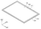
도 1은 본 발명의 실시 예에 따른 커브드 표시장치의 사시도이다.
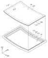
도 2는 도 1a에 도시된 커브드 표시장치의 분해 사시도이다.
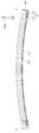
도 3은 도 2에 도시된 I-I’를 따라 절단한 단면도이다.
도 4a는 본 발명의 일 실시 예에 따른 도 3에 도시된 접착 테이프의 단면도이다.
도 4b는 본 발명의 다른 실시 예에 따른 도 3에 도시된 접착 테이프의 단면도이다.
도 5a는 본 발명의 실시 예에 따른 표시패널에 부착된 제1 접착 테이프를 보여주는 사시도이다.
도 5b는 도 5a에 도시된 표시패널의 휘어진 형상을 보여주는 사시도이다.
도 6은 본 발명의 실시 예에 따른 몰드 프레임에 부착된 제2 접착 테이프를 보여주는 사시도이다.
도 7은 본 발명의 실시 예에 따른 표시패널 및 몰드 프레임 간의 부착 방식을 보여주는 사시도이다.
도 8은 도 7에 도시된 II-II’를 따라 절단한 단면도이다.
도 9는 본 발명의 실시 예에 따른 커브드 표시장치의 제조방법을 보여주는 순서도이다.1 is a perspective view of a curved display device according to an embodiment of the present invention.
2 is an exploded perspective view of the curved display device shown in FIG.
3 is a cross-sectional view taken along the line I-I 'shown in FIG.
4A is a cross-sectional view of the adhesive tape shown in Fig. 3 according to an embodiment of the present invention.
4B is a cross-sectional view of the adhesive tape shown in Fig. 3 according to another embodiment of the present invention.
5A is a perspective view showing a first adhesive tape attached to a display panel according to an embodiment of the present invention.
5B is a perspective view showing a curved shape of the display panel shown in FIG. 5A.
6 is a perspective view showing a second adhesive tape attached to a mold frame according to an embodiment of the present invention.
7 is a perspective view showing an attachment method between a display panel and a mold frame according to an embodiment of the present invention.
8 is a cross-sectional view taken along line II-II 'shown in FIG.
9 is a flowchart showing a method of manufacturing a curved display device according to an embodiment of the present invention.
본 발명은 다양한 변경을 가할 수 있고 여러 가지 형태를 가질 수 있는 바, 특정 실시예들을 도면에 예시하고 본문에 상세하게 설명하고자 한다. 그러나, 이는 본 발명을 특정한 개시 형태에 대해 한정하려는 것이 아니며, 본 발명의 사상 및 기술 범위에 포함되는 모든 변경, 균등물 내지 대체물을 포함하는 것으로 이해되어야 한다.The present invention is capable of various modifications and various forms, and specific embodiments are illustrated in the drawings and described in detail in the text. It should be understood, however, that the invention is not intended to be limited to the particular forms disclosed, but includes all modifications, equivalents, and alternatives falling within the spirit and scope of the invention.
각 도면을 설명하면서 유사한 참조부호를 유사한 구성요소에 대해 사용하였다. 첨부된 도면에 있어서, 구조물들의 치수는 본 발명의 명확성을 위하여 실제보다 확대 또는 축소하여 도시한 것이다. 제1, 제2 등의 용어는 다양한 구성요소들을 설명하는데 사용될 수 있지만, 상기 구성요소들은 상기 용어들에 의해 한정되어서는 안 된다. 상기 용어들은 하나의 구성요소를 다른 구성요소로부터 구별하는 목적으로만 사용된다. 예를 들어, 본 발명의 권리 범위를 벗어나지 않으면서 제1 구성요소는 제2 구성요소로 명명될 수 있고, 유사하게 제2 구성요소도 제1 구성요소로 명명될 수 있다. 단수의 표현은 문맥상 명백하게 다르게 뜻하지 않는 한, 복수의 표현을 포함한다.Like reference numerals are used for like elements in describing each drawing. In the attached drawings, the dimensions of the structures are shown enlarged or reduced in size for clarity of the present invention. The terms first, second, etc. may be used to describe various components, but the components should not be limited by the terms. The terms are used only for the purpose of distinguishing one component from another. For example, without departing from the scope of the present invention, the first component may be referred to as a second component, and similarly, the second component may also be referred to as a first component. The singular expressions include plural expressions unless the context clearly dictates otherwise.
본 출원에서, "포함하다" 또는 "가지다" 등의 용어는 명세서 상에 기재된 특징, 숫자, 단계, 동작, 구성요소, 부품 또는 이들을 조합한 것이 존재함을 지정하려는 것이지, 하나 또는 그 이상의 다른 특징들이나 숫자, 단계, 동작, 구성요소, 부분품 또는 이들을 조합한 것들 의 존재 또는 부가 가능성을 미리 배제하지 않는 것으로 이해되어야 한다.In the present application, the terms "comprises" or "having" and the like are used to specify that there is a feature, a number, a step, an operation, an element, a component or a combination thereof described in the specification, But do not preclude the presence or addition of one or more other features, integers, steps, operations, components, parts, or combinations thereof.
도 1은 본 발명의 실시 예에 따른 커브드 표시장치의 사시도이다. 도 2는 도 1에 도시된 커브드 표시장치의 분해 사시도이다. 도 3은 도 2에 도시된 I-I’를 따라 절단한 단면도이다.1 is a perspective view of a curved display device according to an embodiment of the present invention. 2 is an exploded perspective view of the curved display device shown in Fig. 3 is a cross-sectional view taken along the line I-I 'shown in FIG.
본 발명에 따른 커브드 표시장치(DD)는 텔레비전 또는 외부 광고판과 같은 대형 전자 장비를 비롯하여, 퍼스널 컴퓨터, 노트북 컴퓨터, 자동차 네이게이션 유닛, 카메라와 같은 중소형 전자 장비 등에 사용될 수 있다. 또한, 본 발명에 따른 커브드 표시장치(DD)는 태블릿 PC, 스마트폰, PDA(Personal Digital Assistant), PMP(Portable Multimedia Player), 게임기, 손목 시계형 전자 기기 등을 포함할 수 있다. 이것들은 단지 실시 예로 제시된 것들로서, 본 발명의 개념에서 벗어나지 않은 이상 다른 전자 기기에도 채용될 수 있다.The curved display device DD according to the present invention can be used for a large electronic device such as a television or an external billboard, a medium-sized electronic device such as a personal computer, a notebook computer, a car navigation unit, a camera, and the like. In addition, the curved display device DD according to the present invention may include a tablet PC, a smart phone, a PDA (Personal Digital Assistant), a PMP (Portable Multimedia Player), a game machine, a wristwatch type electronic device, and the like. These are merely examples, and may be employed in other electronic devices as long as they do not depart from the concept of the present invention.
또한, 본 발명에 따른 커브드 표시장치(DD)는 휘어진 형상을 갖는다. 커브드 표시장치(DD)가 휘어진 형상을 가짐에 따라, 커브드 표시장치(DD)의 표시면(DS)은 곡면 형상을 가질 수 있다. 곡면 형상의 표시면(DS)을 통해 향상된 입체감, 몰입감 및 임장감을 갖는 영상이 표시 될 수 있다.Further, the curved display device DD according to the present invention has a curved shape. As the curved display device DD has a curved shape, the display surface DS of the curved display device DD can have a curved shape. An image having improved stereoscopic effect, immersion feeling, and sense of urgency can be displayed through the curved surface display surface DS.
도 1을 참조하면, 커브드 표시장치(DD)는 중심축(CC)을 감싸도록 휘어질 수 있다. 실시 예에 따르면, 중심축(CC)은 제1 방향(DR1)과 평행한 라인일 수 있으며, 커브드 표시장치(DD)의 상면 위에 소정 거리(d1)만큼 이격되어 정의될 수 있다. 여기서, 커브드 표시장치(DD)의 상면은 사용자가 영상을 시인하는 면일 수 있다. 따라서, 커브드 표시장치(DD)의 표시면(DS)은 제1 방향(DR1)과 수직하는 제2 방향(DR2)을 따라 휘어진 곡면 형상을 가질 수 있다.Referring to FIG. 1, the curved display device DD can be bent to surround the central axis CC. According to the embodiment, the center axis CC may be a line parallel to the first direction DR1 and may be defined by a predetermined distance d1 on the upper surface of the curved display device DD. Here, the upper surface of the curved display device DD may be a surface on which a user views an image. Therefore, the display surface DS of the curved display device DD may have a curved surface shape curved along the second direction DR2 perpendicular to the first direction DR1.
도 2를 참조하면, 커브드 표시장치(DD)는 커버 부재(100), 수납 부재(200), 표시패널(300), 몰드 프레임(400), 및 백라이트 유닛(500)을 포함한다.2, the curved display device DD includes a
커버 부재(100)는 표시패널(300) 상부에 배치될 수 있다. 커버 부재(100)는 표시패널(300)이 제공하는 영상을 투과시키는 표시 영역(DA)과 표시 영역(DA)에 인접한 비표시 영역(NDA)을 포함한다. 도시되지 않았지만, 커버 부재(100)는 표시 영역(DA)을 통해, 외부로 영상을 투과시키는 윈도우 부재를 더 포함할 수 있다.The
수납 부재(200)는 표시패널(300), 몰드 프레임(400), 및 백라이트 유닛(500)을 수납하며, 커버 부재(100)와 결합될 수 있다. 수납 부재(200)는 바닥부(200a) 및 제3 방향(DR3)을 따라 바닥부(200a)의 모서리들로부터 절곡되어 연장된 복수 개의 측벽들(200b)을 포함할 수 있다.The
표시패널(300)은 커버 부재(100) 및 백라이트 유닛(300) 사이에 배치될 수 있다. 실시 예에 따르면, 표시패널(300)은 액정표시패널 또는 유기발광 표시패널, 전기영동 표시패널, 일렉트로웨팅 표시패널 등일 수 있고, 그 종류가 제한되지 않는다. 이하에서, 본 발명의 설명에 따르면, 액정표시패널이 예시적으로 설명된다.The
자세하게, 표시패널(300)은 제1 기판(310), 제2 기판(320), 및 제1 기판(310) 및 제2 기판(320) 사이에 배치된 액정층(미도시)을 포함한다.In detail, the
도시되지 않았지만, 제1 기판(310)에는 복수의 게이트 라인들, 복수의 데이터 라인들, 및 복수의 화소들이 배치될 수 있다. 화소들은 매트릭스 형태로 배열될 수 있다. 이러한 화소들 각각은 복수의 게이트 라인들 및 복수의 데이터 라인들 중 대응하는 게이트 라인 및 대응하는 데이터 라인에 연결된다. 제2 기판(320)에는 공통 전극 및 컬러 필터가 배치될 수 있다.Although not shown, the
몰드 프레임(400)은 중심?s(CC)을 감싸도록 휘어진 형상을 가질 수 있다. 자세하게, 몰드 프레임(400)은 커버 부재(100) 및 수납 부재(200) 사이에 배치되어, 커버 부재(100) 및 수납 부재(200)와 결합될 수 있다.The
본 발명의 실시 예에 따르면, 도 3에 도시된 바와 같이, 몰드 프레임(400)의 내측은 단차 형상의 단차부를 포함할 수 있다. 자세하게, 몰드 프레임(400)의 단차부는 서로 다른 높이를 갖는 제1 단차부(410) 및 제1 단차부(410)보다 낮은 높이를 갖는 제2 단차부(420)를 포함할 수 있다. 표시패널(300)은 제1 단차부(410) 상면에 배치되며, 광학 시트들(530)은 제2 단차부(420) 상면에 배치된다.According to the embodiment of the present invention, as shown in FIG. 3, the inside of the
또한, 광학 시트들(530)과 표시패널(300) 사이에 소정의 간격이 생기도록 제1 단차부(410)와 제2 단차부(420)의 높이가 설정될 수 있다.In addition, the heights of the
백라이트 유닛(500)은 표시패널(300) 및 수납 부재(200) 사이에 배치될 수 있다. 자세하게, 백라이트 유닛(500)은 반사판(510), 도광판(520), 복수의 광학 시트들(530), 및 백라이트 유닛(LS)을 포함한다.The
반사판(510)은 도광판(520) 및 수납 부재(200) 사이에 배치될 수 있다. 반사판(510)은 폴리에틸렌 테레프탈레이트(polyethylene terephthalate, PET) 및 알루미늄과 같은 광을 반사하는 물질을 포함할 수 있다. 따라서, 반사판(510)은 도광판(520)의 하부에 배치되어, 도광판(520)으로부터 전달된 광을 표시패널(300)로 다시 반사시킬 수 있다.The
도광판(520)은 광학 시트들(530) 및 반사판(510) 사이에 배치되며, 수납 부재(200)에 수납될 수 있다. 도광판(520)의 측면들 중 제2 방향(DR2)을 따라 연장된 어느 일 측면은 백라이트 유닛(LS)과 마주할 수 있다. 즉, 도광판(520)은 백라이트 유닛(LS)의 복수의 발광소자들(LG)로부터 출력된 광을 상기 일 측면을 통해 수신하고, 수신된 광을 표시패널(300)로 전달할 수 있다.The
또한, 도시되지 않았지만, 도광판(520)의 측면들 중 제2 방향(DR2)을 따라 연장된 측면들 모두 백라이트 유닛(LS)과 마주할 수도 있다. 이 경우, 도광판(520)을 사이에 두고 서로 이격된 두 개의 백라이트 유닛들이 제공될 수 있다.Also, although not shown, all of the side surfaces of the
광학 시트들(530)은 표시패널(300) 및 도광판(520) 사이에 배치되며, 몰드 프레임(400)의 제2 단차부(420) 상면에 배치될 수 있다. 이러한 광학 시트들(530)은 도광판(520)으로부터 출사되어 표시패널(DP) 측으로 입사되는 광의 경로를 조절할 수 있다.The
예를 들어, 도 3에 도시된 바와 같이, 광학 시트들(530)은 몰드 프레임(400)의 제2 단차부(420)에 배치될 수 있다. 이 경우, 광학 시트들(530)은 도광판(520)으로부터 출사된 광을 확산시키는 상부 확산시트(531)와 하부 확산시트(533), 및 도광판(520)으로부터 출사된 광을 집광하는 프리즘 시트(532)를 포함할 수 있다. 상부 확산시트(531)는 프리즘 시트(532) 상부에 배치되며, 하부 확산시트(533)는 프리즘 시트(532) 하부에 배치된다.For example, as shown in FIG. 3, the
백라이트 유닛(LS)은 복수의 발광소자들(LG) 및 복수의 발광소자들(LG)이 배치되는 인쇄회로기판(PB)을 포함한다. 백라이트 유닛(LS)은 도광판(520)의 측면들 중 어느 일 측면과 마주하도록 수납 부재(200)에 수납될 수 있다.The backlight unit LS includes a printed circuit board PB on which a plurality of light emitting devices LG and a plurality of light emitting devices LG are disposed. The backlight unit LS may be housed in the receiving
인쇄회로기판(PB)은 제2 방향(DR2)으로 연장된 형상을 가지며, 발광소자들(LG)은 제2 방향(DR2)을 따라 인쇄회로기판(PB) 상에 나열될 수 있다. 이러한 발광소자들(LG)은 영상 표시에 필요한 광을 생성하고, 생성된 광을 도광판(520)의 일 측면으로 출력할 수 있다.The printed circuit board PB has a shape extending in the second direction DR2 and the light emitting elements LG can be arranged on the printed circuit board PB along the second direction DR2. The light emitting devices LG may generate light necessary for displaying an image, and may output the generated light to one side of the
한편, 도 3에 도시된 바와 같이, 표시패널(300)은 접착 테이프(AT)를 이용하여 몰드 프레임(400)에 부착될 수 있다. 자세하게, 접착 테이프(AT)는 몰드 프레임(400)의 제1 단차부(410) 상면 및 제1 기판(310) 사이에 배치된 구조를 가질 수 있다.Meanwhile, as shown in FIG. 3, the
일반적으로, 표시패널과 몰드 프레임이 결합되는 경우, 표시패널 및 몰드 프레임의 단차부는 하나의 접착 테이프를 이용하여 서로 부착될 수 있다. 여기서, 접착 테이프는 양면 접착 테이프일 수 있다. 이 경우, 표시패널 및 몰드 프레임이 결합됨에 따라, 접착 테이프의 일면은 표시패널에 부착되고, 타면은 몰드 프레임의 단차부 상면에 부착된다. 이 후, 접착 테이프(AT)의 접착력을 높이기 위한 에이징(aging) 시간이 진행될 수 있다. 여기서, 표시패널 및 몰드 프레임에 부착된 접착 테이프(AT)는 시간이 경과됨에 따라 더욱 높아진 접착력을 가질 수 있다. 즉, 에이징 시간은 접착 테이프(AT)의 접착력을 높이기 위한 경과 시간으로 정의될 수 있다. 그 결과, 에이징 시간을 통해 표시패널 및 몰드 프레임 간의 접착력이 더욱 높아질 수 있다.In general, when the display panel and the mold frame are joined, the stepped portions of the display panel and the mold frame can be attached to each other by using one adhesive tape. Here, the adhesive tape may be a double-sided adhesive tape. In this case, as the display panel and the mold frame are combined, one surface of the adhesive tape is attached to the display panel, and the other surface is attached to the upper surface of the step portion of the mold frame. Thereafter, an aging time for increasing the adhesive force of the adhesive tape AT may proceed. Here, the adhesive tape (AT) attached to the display panel and the mold frame can have a higher adhesive force as time passes. That is, the aging time can be defined as the elapsed time for increasing the adhesive force of the adhesive tape (AT). As a result, the adhesion between the display panel and the mold frame can be further increased through the aging time.
마찬가지로, 커브드 표시장치의 경우, 접착 테이프를 이용하여 휘어진 표시패널 및 몰드 프레임이 부착된 후, 접착 테이프의 접착력을 높이기 위한 에이징 시간이 필요하다. 이 경우, 휘어진 표시패널 및 몰드 프레임 간의 접착력을 높이기 위한 에이징 시간 동안, 지그(JIG)를 이용하여 휘어진 표시패널을 고정해야 한다. 이는, 휘어진 표시패널의 곡률 특성을 유지하기 위함이다. 그러나, 이러한 휘어진 표시패널 및 몰드 프레임 간의 접착력 향상을 위한 에이징 시간 동안, 지그(JIG)에 의해 표시패널이 손상될 수 있다.Similarly, in the case of the curved display device, after the curved display panel and the mold frame are adhered using the adhesive tape, an aging time is required to increase the adhesive strength of the adhesive tape. In this case, the bent display panel must be fixed using the jig JIG during the aging time for increasing the adhesion between the curved display panel and the mold frame. This is to maintain the curvature characteristic of the curved display panel. However, during the aging time for improving the adhesion between the curved display panel and the mold frame, the display panel may be damaged by the jig JIG.
본 발명의 실시 예에 따르면, 표시패널(300) 및 몰드 프레임(400) 각각에 접착 테이프가 부착될 수 있다. 즉, 본 발명에 따른 접착 테이프(AT)는 표시패널(300) 및 몰드 프레임(400) 각각에 부착될 두 개의 접착 테이프들을 포함할 수 있다.According to the embodiment of the present invention, an adhesive tape can be attached to each of the
특히, 본 발명의 실시 예에 따르면, 표시패널(300) 및 몰드 프레임(400)이 서로 결합되기 전에, 표시패널(300) 및 몰드 프레임(400) 각각에 부착된 접착 테이프들의 에이징 시간이 진행될 수 있다. 또한, 실시 예에 따르면, 표시패널(300)은 부착된 접착 테이프의 에이징 시간이 완료된 후, 중심축(CC)을 기준으로 휘어질 수 있다.Particularly, according to the embodiment of the present invention, before the
이후, 표시패널(300) 및 몰드 프레임(400)이 결합됨에 따라, 표시패널(300)에 부착된 접착 테이프와 몰드 프레임(400)에 부착된 접착 테이프가 서로 부착될 수 있다. 이 경우, 표시패널(300) 및 몰드 프레임(400)이 결합된 후, 별도의 에이징 시간이 필요하지 않다. 즉, 표시패널(300)에 부착된 접착 테이프와 몰드 프레임(400)에 부착된 접착 테이프가 서로 부착됨에 따라, 접착력이 더욱 향상될 수 있다.Thereafter, as the
따라서, 본 발명에 따른 커브드 표시장치(DD)는 제조 과정이 단순해질 수 있으며, 표시패널(300)이 손상되는 위험이 방지될 수 있다. 이에 대해서는 도 5 내지 도 8를 통해 보다 자세히 설명된다.Therefore, the curved display device DD according to the present invention can simplify the manufacturing process, and the risk of damaging the
도 4a는 본 발명의 일 실시 예에 따른 도 3에 도시된 접착 테이프의 단면도이다. 도 4b는 본 발명의 다른 실시 예에 따른 도 3에 도시된 접착 테이프의 단면도이다.4A is a cross-sectional view of the adhesive tape shown in Fig. 3 according to an embodiment of the present invention. 4B is a cross-sectional view of the adhesive tape shown in Fig. 3 according to another embodiment of the present invention.
본 발명의 실시 예에 따르면, 접착 테이프(AT)는 제1 접착 테이프(AT1) 및 제2 접착 테이프(AT2)를 포함할 수 있다.According to the embodiment of the present invention, the adhesive tape AT may include a first adhesive tape AT1 and a second adhesive tape AT2.
자세하게, 도 4a에 도시된 제1 접착 테이프(AT1)는 표시패널(300, 도3 참조) 하부에 배치되어, 표시패널(300)의 하면 및 제2 접착 테이프(AT2)에 부착될 수 있다. 도 4b에 도시된 제2 접착 테이프(AT2)는 몰드 프레임(400, 도3 참조)의 제1 단차부(410) 상면에 배치되고, 제1 단차부(410) 상면 및 제1 접착 테이프(AT1)에 부착될 수 있다. 한편, 표시패널(300)의 상면은 커버 부재(100)와 마주하는 면일 수 있으며, 표시패널(300)의 하면은 백라이트 유닛(500)과 마주하는 면으로 정의된다. 제1 단차부(410)의 상면은 표시패널(300)과 마주하는 면일 수 있으며, 제1 단차부(410)의 하면은 수납 부재(200)와 마주하는 면으로 정의된다.In detail, the first adhesive tape AT1 shown in Fig. 4A is disposed under the display panel 300 (see Fig. 3), and can be attached to the lower surface of the
먼저, 도 3 및 도 4a를 참조하면, 본 발명에 실시 예에 따른 제1 접착 테이프(AT1)는 제1 베이스 필름층(Bfa), 제1 폼층(Fma), 제1 및 제2 접착층들(P1a, P2a), 및 제1 및 제2 보호층들(Pc1a, Pc2a)을 포함한다.Referring to FIGS. 3 and 4A, a first adhesive tape AT1 according to an embodiment of the present invention includes a first base film layer Bfa, a first foam layer Fma, first and second adhesive layers P1a, P2a, and first and second protective layers Pc1a, Pc2a.
제1 베이스 필름층(Bfa)은 지지 부재로, 제1 접착 테이프(AT1)를 전반적으로 지지할 수 있다.The first base film layer Bfa is a supporting member and can support the first adhesive tape AT1 as a whole.
제1 폼층(Fma)은 제1 베이스 필름층(Bfa) 상면에 부착된다. 제1 폼층(Fma)은 대상물과의 접착력을 향상시키기 위한 층으로, 고무 재질로 제공될 수 있다. 즉, 제1 폼층(Fma)은 제1 및 제2 접착층들(P1a, P2a)이 대상물의 접착면에 균일하게 부착되게 하는 역할을 수행한다. 여기서, 대상물은 표시패널(300)일 수 있다. 한편, 제1 폼층(Fma)의 재질로 고무가 설명되었으나, 이에 한정되지 않으며 다양하게 제공될 수 있다.The first foam layer Fma is attached to the upper surface of the first base film layer Bfa. The first foam layer Fma may be provided as a layer for improving the adhesion with the object, and may be made of a rubber material. That is, the first foam layer Fma serves to uniformly attach the first and second adhesive layers P1a and P2a to the adhesive surface of the object. Here, the object may be the
제1 접착층(P1a)은 제1 폼층(Fma) 상면에 부착된다. 제2 접착층(P2a)은 제1 베이스 필름층(Bfa) 하면에 부착될 수 있다.The first adhesive layer P1a is attached to the upper surface of the first foam layer Fma. The second adhesive layer P2a may be adhered to the lower surface of the first base film layer Bfa.
제1 보호층(Pc1a)은 제1 접착층(P1a) 상면에 부착되며, 제1 접착층(P1a)의 접착력을 유지시킨다. 이 경우, 제1 보호층(Pc1a)이 제1 접착층(P1a)으로부터 분리될 경우, 제1 접착층(P1a)의 접착력이 약해질 수 있다. 제2 보호층(Pc2a)은 제2 접착층(P2a) 하면에 부착되며, 제2 접착층(P2a)의 접착력을 유지시킨다. 마찬가지로, 제2 보호층(Pc2a)이 제2 접착층(P2a)으로부터 분리될 경우, 제2 접착층(P2a)의 접착력이 약해질 수 있다.The first protective layer Pc1a is attached to the upper surface of the first adhesive layer P1a and maintains the adhesive force of the first adhesive layer P1a. In this case, when the first protective layer Pc1a is separated from the first adhesive layer P1a, the adhesive strength of the first adhesive layer P1a may be weakened. The second protective layer Pc2a is attached to the lower surface of the second adhesive layer P2a and maintains the adhesive force of the second adhesive layer P2a. Similarly, when the second protective layer Pc2a is separated from the second adhesive layer P2a, the adhesive strength of the second adhesive layer P2a can be weakened.
또한, 도 4b를 참조하면, 제2 접착 테이프(AT2)는 제2 베이스 필름층(Bfb), 제2 폼층(Fmb), 제3 및 제4 접착층들(P2b, P2b), 및 제3 및 제4 보호층들(Pc1b, Pc2b)을 포함한다.4B, the second adhesive tape AT2 includes a second base film layer Bfb, a second foam layer Fmb, third and fourth adhesive layers P2b and P2b, 4 protective layers (Pc1b, Pc2b).
제2 베이스 필름층(Bfb)은 지지 부재로, 제2 접착 테이프(AT2)를 전반적으로 지지할 수 있다.The second base film layer Bfb is a supporting member and can support the second adhesive tape AT2 as a whole.
제2 폼층(Fmb)은 제2 베이스 필름층(Bfb) 하면에 부착된다. 제2 폼층(Fmb)은 대상물과의 접착력을 향상시키기 위한 층으로, 고무 재질로 제공될 수 있다. 제2 폼층(Fmb)은 제3 및 제4 접착층들(P1b, P2b)이 대상물의 접착면에 균일하게 부착되게 하는 역할을 수행한다. 여기서, 대상물은 몰드 프레임(400)일수 있다. 한편, 제2 폼층(Fmb)의 재질로 고무가 설명되었으나, 이에 한정되지 않으며 다양하게 제공될 수 있다.The second foam layer (Fmb) is attached to the lower surface of the second base film layer (Bfb). The second foam layer (Fmb) may be provided as a layer for enhancing the adhesion with the object, and made of a rubber material. The second foam layer Fmb serves to uniformly attach the third and fourth adhesive layers P1b and P2b to the adhesion surface of the object. Here, the object may be the
제3 접착층(P1b)은 제2 폼층(Fmb) 하면에 부착되며, 제4 접착층(P2b)은 제2 베이스 필름층(Bfb) 상면에 부착될 수 있다.The third adhesive layer P1b may adhere to the lower surface of the second foam layer Fmb and the fourth adhesive layer P2b may adhere to the upper surface of the second base film layer Bfb.
제3 보호층(Pc1b)은 제3 접착층(P1b) 하면에 부착되며, 제3 접착층(P1b)의 접착력을 유지시킨다. 이 경우, 제3 보호층(Pc1b)이 제3 접착층(P1b)으로부터 분리될 경우, 제3 접착층(P1b)의 접착력이 약해질 수 있다. 제4 보호층(Pc2b)은 제4 접착층(P2b) 상면에 부착되며, 제4 접착층(P2b)의 접착력을 유지시킨다. 이 경우, 제4 보호층(Pc2b)이 제1 접착층(P1a)으로부터 분리될 경우, 제4 접착층(P2b)의 접착력이 약해질 수 있다.The third protective layer Pc1b is attached to the lower surface of the third adhesive layer P1b and maintains the adhesive force of the third adhesive layer P1b. In this case, when the third protective layer Pc1b is separated from the third adhesive layer P1b, the adhesive force of the third adhesive layer P1b may be weakened. The fourth protective layer Pc2b is attached to the upper surface of the fourth adhesive layer P2b and maintains the adhesive force of the fourth adhesive layer P2b. In this case, when the fourth protective layer Pc2b is separated from the first adhesive layer P1a, the adhesion of the fourth adhesive layer P2b can be weakened.
실시 예에 따르면, 표시패널(300)의 제1 기판(310) 하면은 제1 접착층(P1a)에 부착될 수 있다. 이 경우, 제1 보호층(Pc1a)이 제거된 후, 표시패널(300)의 하면이 제1 접착층(P1a)에 부착될 수 있다.According to the embodiment, the lower surface of the
실시 예에 따르면, 몰드 프레임(400)의 제1 단차부(410) 상면은 제3 접착층(P1b)과 부착될 수 있다. 이 경우, 제3 보호층(Pc1b)이 제거된 후, 몰드 프레임(400)의 제1 단차부(410) 상면이 제3 접착층(P1b)에 부착될 수 있다. 그 결과, 표시패널(300)과 몰드 프레임(400)이 결합됨에 따라, 제2 접착층(P2a)과 제4 접착층(P2b)이 서로 부착될 수 있다.According to the embodiment, the upper surface of the
이하에서, 제1 및 제2 접착 테이프들(AT1, AT2)이 표시패널(300) 및 몰드 프레임(400)에 부착될 경우, 제1 및 제3 보호층들(Pc1a, Pc1b)은 제1 및 제2 접착 테이프들(AT1, AT2)로부터 제거된 것으로 설명된다.Hereinafter, when the first and second adhesive tapes AT1, AT2 are attached to the
한편, 도 4a 및 도 4b를 통해 제1 접착 테이프(AT1) 및 제2 접착 테이프(AT2)의 구조가 서로 다른 것으로 설명되었으나, 본 발명의 기술적 사상은 이에 한정되지 않는다. 즉, 제1 접착 테이프(AT1) 및 제2 접착 테이프(AT2)의 구조는 다양하게 변형되어, 표시패널(300) 및 몰드 프레임(400)에 부착될 수 있다.4A and 4B, the structures of the first adhesive tape AT1 and the second adhesive tape AT2 are different from each other. However, the technical idea of the present invention is not limited thereto. That is, the structure of the first adhesive tape AT1 and the second adhesive tape AT2 may be variously modified and attached to the
도 5a는 본 발명의 실시 예에 따른 표시패널에 부착된 제1 접착 테이프를 보여주는 사시도이다. 도 5b는 도 5a에 도시된 표시패널의 휘어진 형상을 보여주는 사시도이다.5A is a perspective view showing a first adhesive tape attached to a display panel according to an embodiment of the present invention. 5B is a perspective view showing a curved shape of the display panel shown in FIG. 5A.
도 5a 및 도 5b를 참조하면, 제3 방향(DR3)에서, 제1 기판(310)의 하면에 제1 접착 테이프(AT1)가 배치되고, 제1 기판(310)의 상면에 제2 기판(320)이 배치된다.5A and 5B, the first adhesive tape AT1 is disposed on the lower surface of the
본 발명의 실시 예에 따르면, 표시패널(300)이 휘어진 형상을 갖기 이전에, 제1 접착 테이프(AT1)가 표시패널(300)에 부착될 수 있다. 특히, 제1 접착 테이프(AT1)는 제1 기판(310) 하면의 테두리 영역에 부착될 수 있다. 여기서, 제1 기판(310) 하면의 테두리 영역은 비표시 영역(NDA)에 포함될 수 있다.According to the embodiment of the present invention, the first adhesive tape AT1 may be attached to the
또한, 실시 예에 따르면, 제1 기판(310) 하면의 테두리 영역에 제1 접착 테이프(AT1)가 부착된 후, 에이징(aging) 시간이 진행될 수 있다. 그 결과, 일정 시간 경과후에, 제1 기판(310) 하면의 테두리 영역에 부착된 제1 접착 테이프(AT1)의 접착력이 높아질 수 있다. 여기서, 제1 기판(310) 하면의 테두리 영역은 도 6에 도시된 제1 단차부(410) 상면과 적어도 일 부분이 중첩될 수 있다.In addition, according to the embodiment, the aging time may proceed after the first adhesive tape AT1 is attached to the edge area of the lower surface of the
이 후, 도 5b에 도시된 바와 같이, 표시면(DS)이 중심축(CC)을 감싸도록 표시패널(300)이 휘어질 수 있다. 따라서, 본 발명에 따른 커브드 표시장치(DD)의 표시면(DS)은 제1 방향(DR1)과 수직하는 제2 방향(DR2)을 따라 휘어진 곡면 형상을 가질 수 있다.Thereafter, as shown in FIG. 5B, the
도 6은 본 발명의 실시 예에 따른 몰드 프레임에 부착된 제2 접착 테이프를 보여주는 사시도이다.6 is a perspective view showing a second adhesive tape attached to a mold frame according to an embodiment of the present invention.
실시 예에 따르면, 몰드 프레임(400)은 휘어진 형상을 가질 수 있다. 즉, 몰드 프레임(400)은 표시패널(300, 도2 참조)과 마찬가지로, 도 5b에 도시된 바와 같이, 중심축(CC)을 감싸도록 휘어진 형상을 가질 수 있다.According to an embodiment, the
도 6을 참조하면, 몰드 프레임(400)의 내측은 단차 형상의 제1 단차부(410) 및 제2 단차부(420)를 포함한다. 이 경우, 제3 방향(DR3)에서, 제1 단차부(410) 및 제2 단차부(420)는 서로 다른 높이를 가질 수 있다. 도 3에서 설명된 바와 같이, 제1 단차부(410) 상에는 표시패널(300)이 안착되며, 제2 단차부(420) 상에는 광학 시트들(530)이 안착될 수 있다.Referring to FIG. 6, the inside of the
또한, 실시 예에 따르면, 몰드 프레임(400)에는 백라이트 유닛(500, 도2 참조)으로부터 출력된 광이 표시패널(300)에 제공되기 위한 개구부(OP)가 정의될 수 있다. 이러한 개구부(OP)는 표시 영역(DA, 도5a 참조)에 대응하는 개구부(OP)일 수 있다.According to the embodiment, an opening OP for providing the light output from the backlight unit 500 (see FIG. 2) to the
본 발명에 따른 몰드 프레임(400)은 표시패널(300)과 달리, 휘어진 형상으로 제작될 수 있다. 즉, 표시패널(300)과 비교하여, 별도의 휘는 동작 방식이 필요하지 않다. 그 결과, 휘어진 형상을 갖는 몰드 프레임(400)에 제2 접착 테이프(AT2)가 부착될 수 있다. 이러한 제2 접착 테이프(AT2)는 제1 단차부(410) 상면에 개구부(OP)를 둘러싸도록 부착될 수 있다.Unlike the
도 7은 본 발명의 실시 예에 따른 표시패널 및 몰드 프레임 간의 부착 방식을 보여주는 사시도이다. 도 8은 도 7에 도시된 II-II’를 따라 절단한 단면도이다. 도 9는 본 발명의 실시 예에 따른 커브드 표시장치의 제조방법을 보여주는 순서도이다.7 is a perspective view showing an attachment method between a display panel and a mold frame according to an embodiment of the present invention. 8 is a cross-sectional view taken along line II-II 'shown in FIG. 9 is a flowchart showing a method of manufacturing a curved display device according to an embodiment of the present invention.
도 2 및 도 7 내지 도 9를 참조하면, 제1 단계(S110)에서, 표시패널(300) 하면의 테두리 영역에 제1 접착 테이프(AT1)가 부착된다. 여기서, 제1 접착 테이프(AT1)는 제3 방향(DR3)에서 제1 기판(310) 및 제1 단차부(410) 사이에 배치된다.Referring to Figs. 2 and 7 to 9, in a first step S110, a first adhesive tape AT1 is attached to a bottom edge area of the
제2 단계(S120)에서, 몰드 프레임(400)의 제1 단차부(410) 상면에 제2 접착 테이프(AT2)가 부착된다. 제2 접착 테이프(AT2)는 개구부(OP)를 둘러싸도록 제1 단차부(410) 상면에 부착될 수 있다.In the second step S120, the second adhesive tape AT2 is attached to the upper surface of the
한편, 제1 단계(S110) 및 제2 단계(S120)는 서로 바뀔 수 있다. 즉, 제2 접착 테이프(AT2)가 제1 단차부(410) 상면에 부착된 후, 제1 접착 테이프(AT1)가 제1 기판(310) 하면에 부착될 수 있다.On the other hand, the first step S110 and the second step S120 may be mutually exchanged. That is, after the second adhesive tape AT2 is attached to the upper surface of the
제3 단계(S130)에서, 제1 접착 테이프(AT1) 및 제2 접착 테이프(AT2) 각각의 에이징(aging) 시간이 진행될 수 있다. 특히, 제1 접착 테이프(AT1)의 에이징 시간 동안, 표시패널(300)은 휘어진 형상이 아닌 플랫한 형상을 가질 수 있다. 따라서, 표시패널(300)은 에이징 시간 동안, 외부의 지그(JIG) 등에 의해 고정될 필요가 없어, 외부 손상이 방지될 수 있다.In the third step S130, the aging time of each of the first adhesive tape AT1 and the second adhesive tape AT2 can proceed. In particular, during the aging time of the first adhesive tape AT1, the
제4 단계(S140)에서, 에이징된 제1 접착 테이프(AT1)가 부착된 표시패널(300)의 표시면(DS)이 중심축을 감싸도록 표시패널(300)이 휘어진다.In the fourth step S140, the
제5 단계(S150)에서, 제1 접착 테이프(AT1)와 제2 접착 테이프(AT2)가 서로 부착되도록 휘어진 표시패널(300)과 휘어진 몰드 프레임(400)이 서로 결합된다. 이 경우, 표시패널(300)이 외부의 지그(JIG) 등에 의해 고정된 후, 제3 방향(DR3)을 따라 제1 단차부(410) 상면에 부착될 수 있다. 그 결과, 제1 접착 테이프(AT1)와 제2 접착 테이프(AT2)가 서로 부착될 수 있다.In the fifth step S150, the
도 8에 도시된 바와 같이, 휘어진 표시패널(300)과 휘어진 몰드 프레임(400)이 서로 결합될 경우, 제1 접착 테이프(AT1)와 제2 접착 테이프(AT2)가 서로 부착된 구조를 가질 수 있다.8, when the
이상에서와 같이 도면과 명세서에서 실시 예가 개시되었다. 여기서 특정한 용어들이 사용되었으나, 이는 단지 본 발명을 설명하기 위한 목적에서 사용된 것이지 의미 한정이나 특허 청구범위에 기재된 본 발명의 범위를 제한하기 위하여 사용된 것은 아니다. 그러므로 본 기술분야의 통상의 지식을 가진 자라면 이로부터 다양한 변형 및 균등한 타 실시 예가 가능하다는 점을 이해할 것이다. 따라서 본 발명의 진정한 기술적 보호 범위는 첨부된 특허 청구범위의 기술적 사상에 의해 정해져야 할 것이다.The embodiments have been disclosed in the drawings and specification as described above. Although specific terms have been employed herein, they are used for purposes of illustration only and are not intended to limit the scope of the invention as defined in the claims or the claims. Therefore, those skilled in the art will appreciate that various modifications and equivalent embodiments are possible without departing from the scope of the present invention. Accordingly, the true scope of the present invention should be determined by the technical idea of the appended claims.
100: 커버 부재
200: 수납 부재
300: 표시패널
400: 몰드 프레임
500: 백라이트 유닛100: cover member
200:
300: Display panel
400: Mold frame
500: Backlight unit
Claims (15)
Translated fromKorean상기 표시패널 하면의 테두리 영역에 부착된 제1 접착 테이프;
상기 표시패널이 안착되는 단차부를 포함하는 몰드 프레임; 및
상기 단차부 상면 및 상기 제1 접착 테이프에 부착된 제2 접착 테이프를 포함하는 커브드 표시장치.A display panel in which the display surface is bent so as to surround the central axis;
A first adhesive tape attached to an edge area of the lower surface of the display panel;
A mold frame including a step portion on which the display panel is mounted; And
And a second adhesive tape attached to the stepped upper surface and the first adhesive tape.
상기 표시패널은,
제1 기판; 및
상기 제1 기판 상부에 배치된 제2 기판을 포함하고,
상기 제1 기판 하면의 테두리 영역에 상기 제1 접착 테이프가 부착된 커브드 표시장치.The method according to claim 1,
In the display panel,
A first substrate; And
And a second substrate disposed on the first substrate,
And the first adhesive tape is attached to an edge area of the lower surface of the first substrate.
상기 제1 접착 테이프는,
상기 제1 기판 하면에 부착된 제1 접착층;
상기 제1 접착층 하면에 부착된 제1 폼층;
상기 제1 폼층 하면에 부착된 제1 베이스 필름층; 및
상기 제1 베이스 필름층 하면에 부착된 제2 접착층을 포함하는 커브드 표시장치.3. The method of claim 2,
Wherein the first adhesive tape
A first adhesive layer attached to a lower surface of the first substrate;
A first foam layer attached to a bottom surface of the first adhesive layer;
A first base film layer attached to the first foam layer bottom surface; And
And a second adhesive layer adhered to a lower surface of the first base film layer.
상기 제2 접착 테이프는,
상기 단차부 상면에 부착된 제3 접착층;
상기 제3 접착층 상면에 부착된 제2 폼층;
상기 제2 폼층 상면에 부착된 제2 베이스 필름층; 및
상기 제2 베이스 필름층 상면 및 상기 제2 접착층에 부착된 제4 접착층을 포함하는 커브드 표시장치.The method of claim 3,
Wherein the second adhesive tape
A third adhesive layer attached to the upper surface of the step portion;
A second foam layer attached to an upper surface of the third adhesive layer;
A second base film layer attached to the upper surface of the second foam layer; And
And a fourth adhesive layer adhered to the upper surface of the second base film layer and the second adhesive layer.
상기 제1 기판 하면의 상기 테두리 영역은 상기 단차부 상면과 적어도 일 부분이 중첩된 것을 특징으로 하는 커브드 표시장치.3. The method of claim 2,
Wherein the edge region of the lower surface of the first substrate is overlapped with at least a portion of the upper surface of the step portion.
상기 표시패널은 표시 영역 및 비표시 영역을 포함하고,
상기 몰드 프레임은 상기 표시 영역에 대응하는 개구부가 정의되며, 상기 단차부는 상기 개구부를 둘러싸는 커브드 표시장치.The method according to claim 1,
Wherein the display panel includes a display area and a non-display area,
Wherein the mold frame defines an opening corresponding to the display area and the step surrounds the opening.
상기 제1 및 제2 접착 테이프들 각각은 양면 접착 테이프인 것을 특징으로 하는 커브드 표시장치.The method according to claim 1,
Wherein each of the first and second adhesive tapes is a double-sided adhesive tape.
상기 단차부는 상기 휘어진 표시패널이 안착되도록 상기 중심축을 감싸도록 휘어진 것을 특징으로 하는 커브드 표시장치.8. The method of claim 7,
Wherein the stepped portion is bent so as to surround the center axis so that the curved display panel is seated.
상기 표시패널이 안착되는 몰드 프레임의 단차부 상면에 제2 접착 테이프를 부착하는 단계;
상기 제1 접착 테이프 및 상기 제2 접착 테이프 각각을 에이징하는 단계;
상기 에이징된 제1 접착 테이프가 부착된 상기 표시패널의 표시면이 중심축을 감싸도록 상기 표시패널을 휘는 단계; 및
상기 제1 접착 테이프와 상기 제2 접착 테이프가 부착되도록 상기 휘어진 표시패널과 상기 몰드 프레임을 결합하는 단계를 포함하는 커브드 표시장치의 제조 방법.Attaching a first adhesive tape along an edge area of the lower surface of the display panel;
Attaching a second adhesive tape to an upper surface of a stepped portion of the mold frame on which the display panel is seated;
Aging each of the first adhesive tape and the second adhesive tape;
Bending the display panel so that a display surface of the display panel to which the aged first adhesive tape is attached wraps around a central axis; And
And combining the curved display panel and the mold frame so that the first adhesive tape and the second adhesive tape are adhered to each other.
상기 제1 접착 테이프는,
상기 표시패널 하면에 부착된 제1 접착층;
상기 제1 접착층 하면에 부착된 제1 폼층;
상기 제1 폼층 하면에 부착된 제1 베이스 필름층; 및
상기 제1 베이스 필름층 하면에 부착된 제2 접착층을 포함하는 커브드 표시장치의 제조방법.10. The method of claim 9,
Wherein the first adhesive tape
A first adhesive layer attached to a bottom surface of the display panel;
A first foam layer attached to a bottom surface of the first adhesive layer;
A first base film layer attached to the first foam layer bottom surface; And
And a second adhesive layer adhered to a lower surface of the first base film layer.
상기 제2 접착 테이프는,
상기 단차부 상면에 부착된 제3 접착층;
상기 제3 접착층 상면에 부착된 제2 폼층;
상기 제2 폼층 상면에 부착된 제2 베이스 필름층; 및
상기 제2 베이스 필름층 상면 및 상기 제2 접착층에 부착된 제4 접착층을 포함하는 커브드 표시장치의 제조방법.11. The method of claim 10,
Wherein the second adhesive tape
A third adhesive layer attached to the upper surface of the step portion;
A second foam layer attached to an upper surface of the third adhesive layer;
A second base film layer attached to the upper surface of the second foam layer; And
And a fourth adhesive layer attached to the upper surface of the second base film layer and the second adhesive layer.
상기 제1 접착 테이프는 상기 제2 접착층 하면에 배치된 제1 보호층을 더 포함하고,
상기 휘어진 표시패널과 상기 몰드 프레임을 결합하는 단계 이전에, 상기 제1 보호층이 상기 제2 접착층 하면으로부터 분리되는 단계를 더 포함하는 커브드 표시장치의 제조방법.12. The method of claim 11,
Wherein the first adhesive tape further comprises a first protective layer disposed on a lower surface of the second adhesive layer,
Further comprising the step of separating the first protective layer from the second adhesive layer surface before the step of joining the curved display panel and the mold frame.
상기 제2 접착 테이프는 상기 제4 접착층 상면에 배치된 제2 보호층을 더 포함하고,
상기 휘어진 표시패널과 상기 몰드 프레임을 결합하는 단계 이전에, 상기 제2 보호층이 상기 제4 접착층 상면으로부터 분리되는 단계를 더 포함하는 커브드 표시장치의 제조방법.12. The method of claim 11,
Wherein the second adhesive tape further comprises a second protective layer disposed on an upper surface of the fourth adhesive layer,
Further comprising the step of separating the second protective layer from the top surface of the fourth adhesive layer before the step of joining the curved display panel and the mold frame.
상기 표시패널은 표시 영역과 비표시 영역을 포함하고,
상기 몰드 프레임은 상기 표시 영역에 대응하는 개구부가 정의되며, 상기 단차부는 상기 개구부를 둘러싸는 커브드 표시장치의 제조방법.10. The method of claim 9,
Wherein the display panel includes a display area and a non-display area,
Wherein the mold frame defines an opening corresponding to the display area and the step surrounds the opening.
상기 단차부는 상기 휘어진 표시패널이 안착되도록 상기 중심축을 감싸도록 휘어진 것을 특징으로 하는 커브드 표시장치의 제조방법.
10. The method of claim 9,
Wherein the stepped portion is bent to surround the center axis so that the curved display panel is seated.
Priority Applications (3)
| Application Number | Priority Date | Filing Date | Title |
|---|---|---|---|
| KR1020150172633AKR20170066761A (en) | 2015-12-04 | 2015-12-04 | Curved display device and manufacturing method thereof |
| US15/200,034US10133100B2 (en) | 2015-12-04 | 2016-07-01 | Curved display device and method for manufacturing the same |
| CN201610821698.2ACN106873207B (en) | 2015-12-04 | 2016-09-13 | Curved display device and method for manufacturing curved display device |
Applications Claiming Priority (1)
| Application Number | Priority Date | Filing Date | Title |
|---|---|---|---|
| KR1020150172633AKR20170066761A (en) | 2015-12-04 | 2015-12-04 | Curved display device and manufacturing method thereof |
Publications (1)
| Publication Number | Publication Date |
|---|---|
| KR20170066761Atrue KR20170066761A (en) | 2017-06-15 |
Family
ID=58798968
Family Applications (1)
| Application Number | Title | Priority Date | Filing Date |
|---|---|---|---|
| KR1020150172633ACeasedKR20170066761A (en) | 2015-12-04 | 2015-12-04 | Curved display device and manufacturing method thereof |
Country Status (3)
| Country | Link |
|---|---|
| US (1) | US10133100B2 (en) |
| KR (1) | KR20170066761A (en) |
| CN (1) | CN106873207B (en) |
Cited By (4)
| Publication number | Priority date | Publication date | Assignee | Title |
|---|---|---|---|---|
| KR20190012645A (en)* | 2017-07-28 | 2019-02-11 | 현대모비스 주식회사 | Curved display device for automotive and manufacturing method thereof |
| KR20210000801A (en) | 2019-06-25 | 2021-01-07 | 희성전자 주식회사 | Back light unit of curved display |
| KR20210085126A (en)* | 2019-12-30 | 2021-07-08 | 엘지디스플레이 주식회사 | Display appratus for preventing air bubble of adhesive layer |
| KR102494950B1 (en) | 2022-07-28 | 2023-02-06 | (주)알루코 | bending machine for curved display |
Families Citing this family (10)
| Publication number | Priority date | Publication date | Assignee | Title |
|---|---|---|---|---|
| KR101866314B1 (en)* | 2016-07-12 | 2018-06-12 | (주)코텍 | Curved type display device |
| JP2019191261A (en)* | 2018-04-19 | 2019-10-31 | 三菱電機株式会社 | Liquid crystal display device |
| KR101969507B1 (en)* | 2018-08-07 | 2019-04-16 | 엘지전자 주식회사 | Display divice |
| TWI683291B (en)* | 2018-09-18 | 2020-01-21 | 宏碁股份有限公司 | Display device and manufacturing method thereof |
| KR102798029B1 (en)* | 2018-11-19 | 2025-04-18 | 삼성디스플레이 주식회사 | Aging system and method of aging a display device |
| KR102652550B1 (en)* | 2019-02-13 | 2024-03-29 | 삼성디스플레이 주식회사 | Curved display device |
| CN110308580B (en)* | 2019-06-26 | 2025-05-13 | 厦门天马微电子有限公司 | Curved liquid crystal display device and method for manufacturing the same |
| US12025872B2 (en) | 2019-07-31 | 2024-07-02 | Beijing Boe Optoelectronics Technology Co., Ltd. | Display module |
| CN112305798B (en)* | 2019-07-31 | 2025-03-21 | 京东方科技集团股份有限公司 | Display module and display device |
| KR20220077662A (en)* | 2020-12-02 | 2022-06-09 | 현대자동차주식회사 | Display device and automobile including the same |
Family Cites Families (15)
| Publication number | Priority date | Publication date | Assignee | Title |
|---|---|---|---|---|
| US6977808B2 (en) | 1999-05-14 | 2005-12-20 | Apple Computer, Inc. | Display housing for computing device |
| KR20040009902A (en) | 2002-07-26 | 2004-01-31 | 삼성전자주식회사 | Back light assembly using the same and liquid crystal display device |
| WO2004049050A1 (en) | 2002-11-22 | 2004-06-10 | Koninklijke Philips Electronics N.V. | Method of manufacturing a curved display |
| US7436469B2 (en) | 2004-10-15 | 2008-10-14 | 3M Innovative Properties Company | Composite diffuser plates and direct-lit liquid crystal displays using same |
| KR100852887B1 (en)* | 2006-12-27 | 2008-08-19 | 한국스카파테이프(주) | Double sided acrylic foam tape for mobile phone with base layer |
| JP5094250B2 (en)* | 2007-07-10 | 2012-12-12 | 株式会社ジャパンディスプレイイースト | Display device |
| KR100985152B1 (en)* | 2007-10-31 | 2010-10-05 | 듀폰-미츠이 폴리케미칼 가부시키가이샤 | Laminated film or sheet and surface protection film or sheet |
| JP5174781B2 (en) | 2009-10-15 | 2013-04-03 | 三菱電機株式会社 | Display device and manufacturing method thereof |
| KR101300021B1 (en) | 2011-09-05 | 2013-08-29 | 주식회사 토비스 | Method for manufacturing display panel with curved shape |
| WO2013118475A1 (en)* | 2012-02-07 | 2013-08-15 | シャープ株式会社 | Display apparatus |
| KR101319543B1 (en)* | 2012-05-17 | 2013-10-21 | 삼성디스플레이 주식회사 | Curved dispaly apparatus and multi display apparatus including the same |
| CN103629564A (en)* | 2012-08-28 | 2014-03-12 | 友达光电股份有限公司 | Backlight module and display device |
| KR20140141142A (en) | 2013-05-31 | 2014-12-10 | (주)엔알씨 | Curved display and fabricating method thereof |
| JP2015106045A (en) | 2013-11-29 | 2015-06-08 | 株式会社ジャパンディスプレイ | Flat display device and manufacturing method thereof |
| CN204062723U (en)* | 2014-09-25 | 2014-12-31 | 京东方光科技有限公司 | A kind of backlight module and display unit |
- 2015
- 2015-12-04KRKR1020150172633Apatent/KR20170066761A/ennot_activeCeased
- 2016
- 2016-07-01USUS15/200,034patent/US10133100B2/enactiveActive
- 2016-09-13CNCN201610821698.2Apatent/CN106873207B/enactiveActive
Cited By (4)
| Publication number | Priority date | Publication date | Assignee | Title |
|---|---|---|---|---|
| KR20190012645A (en)* | 2017-07-28 | 2019-02-11 | 현대모비스 주식회사 | Curved display device for automotive and manufacturing method thereof |
| KR20210000801A (en) | 2019-06-25 | 2021-01-07 | 희성전자 주식회사 | Back light unit of curved display |
| KR20210085126A (en)* | 2019-12-30 | 2021-07-08 | 엘지디스플레이 주식회사 | Display appratus for preventing air bubble of adhesive layer |
| KR102494950B1 (en) | 2022-07-28 | 2023-02-06 | (주)알루코 | bending machine for curved display |
Also Published As
| Publication number | Publication date |
|---|---|
| CN106873207B (en) | 2021-09-28 |
| US20170160580A1 (en) | 2017-06-08 |
| US10133100B2 (en) | 2018-11-20 |
| CN106873207A (en) | 2017-06-20 |
Similar Documents
| Publication | Publication Date | Title |
|---|---|---|
| KR20170066761A (en) | Curved display device and manufacturing method thereof | |
| US9069207B2 (en) | Display device | |
| JP5222229B2 (en) | Display device | |
| US11252835B2 (en) | Bendable cover, bendable display module, and bendable terminal device | |
| JP6850550B2 (en) | Curved display device and its manufacturing method | |
| KR102167504B1 (en) | Manufacturing device for display device | |
| CN108227259B (en) | electronic device | |
| US20130236680A1 (en) | Display device and method for manufacturing the same | |
| CN105511181B (en) | Narrow frame flat-panel monitor | |
| KR102515094B1 (en) | Backlight unit, display device and method of manufacturing the display device | |
| KR101921010B1 (en) | Display module and electronic device having said display module | |
| US9983426B2 (en) | Display module and display device comprising display module | |
| JP2019194681A (en) | Display device | |
| JP6689727B2 (en) | Backlight device and display device including the same | |
| JP2016161936A (en) | Display device and manufacturing method for the same | |
| CN108121110A (en) | Liquid crystal display device and the electronic device including liquid crystal display device | |
| KR102492618B1 (en) | Display device | |
| WO2019142620A1 (en) | Surface light source device, display device, and electronic device | |
| KR102514130B1 (en) | Display device and manufacturing mehtod thereof | |
| US20170255043A1 (en) | Structural components of liquid crystal panels and gate cofs and liquid crystal devices | |
| KR102116442B1 (en) | Backlight unit and liquid crystal display device including the same | |
| KR101463683B1 (en) | Liquid Crystal Display Device | |
| JP3657601B2 (en) | Liquid crystal display | |
| JP2010060883A (en) | Display device | |
| KR102372343B1 (en) | Display Device |
Legal Events
| Date | Code | Title | Description |
|---|---|---|---|
| PA0109 | Patent application | Patent event code:PA01091R01D Comment text:Patent Application Patent event date:20151204 | |
| PG1501 | Laying open of application | ||
| A201 | Request for examination | ||
| PA0201 | Request for examination | Patent event code:PA02012R01D Patent event date:20201204 Comment text:Request for Examination of Application Patent event code:PA02011R01I Patent event date:20151204 Comment text:Patent Application | |
| E902 | Notification of reason for refusal | ||
| PE0902 | Notice of grounds for rejection | Comment text:Notification of reason for refusal Patent event date:20220321 Patent event code:PE09021S01D | |
| AMND | Amendment | ||
| E601 | Decision to refuse application | ||
| PE0601 | Decision on rejection of patent | Patent event date:20220926 Comment text:Decision to Refuse Application Patent event code:PE06012S01D Patent event date:20220321 Comment text:Notification of reason for refusal Patent event code:PE06011S01I | |
| X091 | Application refused [patent] | ||
| AMND | Amendment | ||
| PX0901 | Re-examination | Patent event code:PX09011S01I Patent event date:20220926 Comment text:Decision to Refuse Application Patent event code:PX09012R01I Patent event date:20220523 Comment text:Amendment to Specification, etc. | |
| PX0601 | Decision of rejection after re-examination | Comment text:Decision to Refuse Application Patent event code:PX06014S01D Patent event date:20230109 Comment text:Amendment to Specification, etc. Patent event code:PX06012R01I Patent event date:20221226 Comment text:Decision to Refuse Application Patent event code:PX06011S01I Patent event date:20220926 Comment text:Amendment to Specification, etc. Patent event code:PX06012R01I Patent event date:20220523 Comment text:Notification of reason for refusal Patent event code:PX06013S01I Patent event date:20220321 | |
| X601 | Decision of rejection after re-examination |