KR20170066627A - Rotating lance head steam generator lancing system - Google Patents
Rotating lance head steam generator lancing systemDownload PDFInfo
- Publication number
- KR20170066627A KR20170066627AKR1020177012649AKR20177012649AKR20170066627AKR 20170066627 AKR20170066627 AKR 20170066627AKR 1020177012649 AKR1020177012649 AKR 1020177012649AKR 20177012649 AKR20177012649 AKR 20177012649AKR 20170066627 AKR20170066627 AKR 20170066627A
- Authority
- KR
- South Korea
- Prior art keywords
- steam generator
- lance
- tube
- fluid
- flexible
- Prior art date
- Legal status (The legal status is an assumption and is not a legal conclusion. Google has not performed a legal analysis and makes no representation as to the accuracy of the status listed.)
- Granted
Links
Images


Classifications
- B—PERFORMING OPERATIONS; TRANSPORTING
- B08—CLEANING
- B08B—CLEANING IN GENERAL; PREVENTION OF FOULING IN GENERAL
- B08B3/00—Cleaning by methods involving the use or presence of liquid or steam
- B08B3/02—Cleaning by the force of jets or sprays
- B—PERFORMING OPERATIONS; TRANSPORTING
- B08—CLEANING
- B08B—CLEANING IN GENERAL; PREVENTION OF FOULING IN GENERAL
- B08B3/00—Cleaning by methods involving the use or presence of liquid or steam
- B08B3/02—Cleaning by the force of jets or sprays
- B08B3/024—Cleaning by means of spray elements moving over the surface to be cleaned
- B—PERFORMING OPERATIONS; TRANSPORTING
- B08—CLEANING
- B08B—CLEANING IN GENERAL; PREVENTION OF FOULING IN GENERAL
- B08B9/00—Cleaning hollow articles by methods or apparatus specially adapted thereto
- B08B9/02—Cleaning pipes or tubes or systems of pipes or tubes
- B08B9/023—Cleaning the external surfaces
- F—MECHANICAL ENGINEERING; LIGHTING; HEATING; WEAPONS; BLASTING
- F22—STEAM GENERATION
- F22B—METHODS OF STEAM GENERATION; STEAM BOILERS
- F22B37/00—Component parts or details of steam boilers
- F22B37/02—Component parts or details of steam boilers applicable to more than one kind or type of steam boiler
- F22B37/48—Devices or arrangements for removing water, minerals or sludge from boilers ; Arrangement of cleaning apparatus in boilers; Combinations thereof with boilers
- F22B37/483—Devices or arrangements for removing water, minerals or sludge from boilers ; Arrangement of cleaning apparatus in boilers; Combinations thereof with boilers specially adapted for nuclear steam generators
- F—MECHANICAL ENGINEERING; LIGHTING; HEATING; WEAPONS; BLASTING
- F22—STEAM GENERATION
- F22B—METHODS OF STEAM GENERATION; STEAM BOILERS
- F22B37/00—Component parts or details of steam boilers
- F22B37/02—Component parts or details of steam boilers applicable to more than one kind or type of steam boiler
- F22B37/48—Devices or arrangements for removing water, minerals or sludge from boilers ; Arrangement of cleaning apparatus in boilers; Combinations thereof with boilers
- F22B37/486—Devices for removing water, minerals or sludge from boilers
- F—MECHANICAL ENGINEERING; LIGHTING; HEATING; WEAPONS; BLASTING
- F28—HEAT EXCHANGE IN GENERAL
- F28G—CLEANING OF INTERNAL OR EXTERNAL SURFACES OF HEAT-EXCHANGE OR HEAT-TRANSFER CONDUITS, e.g. WATER TUBES OR BOILERS
- F28G1/00—Non-rotary, e.g. reciprocated, appliances
- F28G1/16—Non-rotary, e.g. reciprocated, appliances using jets of fluid for removing debris
- F28G1/166—Non-rotary, e.g. reciprocated, appliances using jets of fluid for removing debris from external surfaces of heat exchange conduits
- F—MECHANICAL ENGINEERING; LIGHTING; HEATING; WEAPONS; BLASTING
- F28—HEAT EXCHANGE IN GENERAL
- F28G—CLEANING OF INTERNAL OR EXTERNAL SURFACES OF HEAT-EXCHANGE OR HEAT-TRANSFER CONDUITS, e.g. WATER TUBES OR BOILERS
- F28G15/00—Details
- F28G15/003—Control arrangements
- F—MECHANICAL ENGINEERING; LIGHTING; HEATING; WEAPONS; BLASTING
- F28—HEAT EXCHANGE IN GENERAL
- F28G—CLEANING OF INTERNAL OR EXTERNAL SURFACES OF HEAT-EXCHANGE OR HEAT-TRANSFER CONDUITS, e.g. WATER TUBES OR BOILERS
- F28G15/00—Details
- F28G15/04—Feeding and driving arrangements, e.g. power operation
Landscapes
- Engineering & Computer Science (AREA)
- Mechanical Engineering (AREA)
- General Engineering & Computer Science (AREA)
- Physics & Mathematics (AREA)
- Chemical & Material Sciences (AREA)
- Combustion & Propulsion (AREA)
- Thermal Sciences (AREA)
- High Energy & Nuclear Physics (AREA)
- Cleaning In General (AREA)
- Nozzles (AREA)
- Cleaning By Liquid Or Steam (AREA)
Abstract
Translated fromKoreanDescription
Translated fromKorean관련 출원들Related Applications
본 출원은 35 U.S.C. §§119, 120, 363, 365 및 37 C.F.R. §1.55 및 §1.78 하에 2014 년 10 월 10 일자로 출원된 미국 가출원 일련번호 제 62/062,277 호에 대한 우선권 및 이익을 주장하며, 이는 인용에 의해 본원에 참조된다.This application claims the benefit of 35 U.S.C. 119, 120, 363, 365 and 37 C.F.R. U.S. Provisional Application Serial No. 62 / 062,277, filed October 10, 2014, under §1.55 and §1.78, which is hereby incorporated by reference herein.
발명의 내용Description of invention
본 발명은 증기 발생기(steam generator) 세정 시스템들에 관한 것이다.The present invention relates to steam generator cleaning systems.
종래의 증기 발생기 랜스 세정 시스템들(lance cleaning systems)은 전형적으로 증기 발생기의 NTL(No Tube Lane) 영역으로부터 도입되는 가요성(flexible) 및/또는 강성(rigid) 튜빙 랜스들을 사용한다. 미국 특허 제 RE 38,542 호; 7,086,353; 8,468,981; 및 공개된 미국 특허 출원 제 2009/0211612 호는 모두 인용에 의해 본원에 통합된다. 일부 가요성 랜스들은 금속 또는 복합재 재료 위브(weave)로 감싸진 가요성 플라스틱 호스들을 활용한다. 전형적으로, 이들 랜스들은 분절화된 척추(segmented vertebrae) 또는 연속적인 가요성 채널 하우징들을 사용하며, 3 mm 초과의 인터 튜브 갭 클리어런스(inter-tube gap clearance)를 요구한다. 3 mm 미만의 튜브 갭들을 갖는 증기 발생기들의 도입에 의해, 슬러지 세정(sludge cleaning) 서비스들을 제공하는데 효과적이고 효율적인 수단에 대한 필요가 존재한다.Conventional steam generator lance cleaning systems typically use flexible and / or rigid tubing lances introduced from the NTL (No Tube Lane) region of the steam generator. U.S. Pat. No. Re. 38,542; 7,086,353; 8,468,981; And Published U.S. Patent Application No. 2009/0211612 are all incorporated herein by reference. Some flexible lances utilize flexible plastic hoses wrapped in a metal or composite material weave. Typically, these lances use segmented vertebrae or continuous flexible channel housings and require an inter-tube gap clearance of greater than 3 mm. By the introduction of steam generators having tube gaps of less than 3 mm there is a need for an effective and efficient means of providing sludge cleaning services.
본 발명은 관절식 랜스 가이드(articulating lance guide) 및 관절식 랜스 가이드를 지지하며 증기 발생기 중심 구역 인터 튜브 레인에 근접하게 관절식 랜스 가이드를 포지셔닝시키는 증기 발생기 NTL에 배치되는 관절식 가이드 레일(articulating guide rail)을 포함할 수 있는 증기 발생기 세정 시스템을 특징으로 한다. 가요성 랜스는 관절식 랜스 가이드 내부로부터 연장 가능하다. 가요성 랜스는 바람직하게는, 센터 돔/실린더 영역에 인접한 인터 튜브 구역에서 증기 발생기 내에서의 튜브들의 하나의 열에서 제 1 튜브와 결합하기 위한 오목한 표면(concave surface)을 포함하는 튜브 레인 정렬 가이드를 갖는 헤드를 포함한다. 헤드 상의 회전 유체 제트(fluid jet) 조립체는 튜브들의 하나의 열의 제 1 튜브와 튜브들의 다른 열의 인접한 제 1 튜브 사이의 인터 튜브 레인의 중심에 유체를 지향시키기 위해 튜브 레인 정렬 가이드에 바로 인접한다(closely adjacent).The present invention relates to an articulating lance guide and an articulating guide which supports an articulated lance guide and which is disposed in a steam generator NTL that positions the articulated lance guide proximate to the steam generator center section intralayer lane rail, which may include a steam generator. The flexible lance is extendable from within the articulated lance guide. The flexible lance preferably includes a concave surface for coupling with the first tube in one row of tubes in the steam generator in an intertube region adjacent the center dome / Lt; / RTI > The rotating fluid jet assembly on the head immediately adjoins the tube lane alignment guide to direct fluid to the center of the intertube lane between the first tube of one row of tubes and the adjacent first tube of another row of tubes closely adjacent.
랜스 헤드는 유체 제트의 분사력(jetting force)을 오프셋하도록 포지셔닝되는 회전 유체 제트 조립체 상에 노즐(nozzle)을 더 포함할 수 있다. 일 설계에서, 랜스 헤드는 고정구(fixture)를 포함하고, 회전 유체 제트 조립체는 고정구에 대해 회전 가능한 배럴(barrel)을 포함하고, 유체 피팅(fluid fitting)이 배럴 상에 포함된다. 드라이브 케이블(drive cable)이 가요성 랜스 및 랜스 헤드 고정구를 통해 연장할 수 있고 회전 가능한 배럴에 연결된다. 케이블은 리니어(linear) 증기 발생기 튜브 시트 유체 제트 속도를 달성하기 위해 가변 회전 속도(variable rate of rotation)로 드라이브 케이블을 통해 회전 가능한 배럴을 회전시키게 모터를 제어하도록 구성되는 제어기를 갖는 모터에 의해 구동될 수 있다. 일부 실시예들에서, 랜스 헤드 고정구에 대해 일단부 상에 연결되고, 유체 피팅에 대해 반대편 단부 상에 연결되며, 회전 가능한 배럴 주위를 루핑하는(looping) 가요성 유체 공급 호스(hose)가 존재한다. 유체 공급 호스는 가요성 랜스를 통해 연장하고 랜스 헤드 고정구에 연결된다. 강성 튜브는 가요성 유체 공급 호스로부터 유체를 수용하는 유체 피팅에 연결될 수 있다. 노즐이 강성 튜브의 말단부에 포함될 수 있다. 배럴 상의 유체 피팅은 카운터밸런싱(counterbalancing) 워터 제트를 생성하는 후방 노즐을 포함할 수 있다. 프로브(probe)가 고정구 상에 포함될 수 있고 프로브 케이블(probe cable)이 가요성 랜스를 통해 연장한다.The lance head may further include a nozzle on a rotating fluid jet assembly positioned to offset the jetting force of the fluid jet. In one design, the lance head includes a fixture, the rotating fluid jet assembly includes a barrel rotatable relative to the fixture, and a fluid fitting is included on the barrel. A drive cable is connected to the rotatable barrel and extendable through the flexible lance and lance head anchor. The cable is driven by a motor having a controller configured to control the motor to rotate the barrel rotatable through the drive cable at a variable rate of rotation to achieve a linear steam generator tube seat fluid jet velocity . In some embodiments, there is a flexible fluid supply hose that is connected on one end to the lance head fixture and is connected on the opposite end to the fluid fitting, and that loops around the rotatable barrel . The fluid supply hose extends through the flexible lance and is connected to the lance head fixture. The rigid tube may be connected to a fluid fitting that receives fluid from the flexible fluid supply hose. The nozzle may be included in the distal end of the rigid tube. The fluid fitting on the barrel may include a rear nozzle to create a counterbalancing water jet. A probe can be included on the fixture and a probe cable extends through the flexible lance.
그러나, 본 발명은 다른 실시예들에서 이들 모든 목적들을 달성할 필요가 없으며, 본원의 청구항들은 이들 목적들을 달성할 수 있는 구조들 또는 방법들로 제한되어서는 안 된다.However, the present invention is not required to achieve all of these objectives in other embodiments, and the claims of the present application should not be limited to structures or methods capable of achieving these objects.
다른 목적들, 특징들 및 이점들이 하기 바람직한 실시예 및 첨부된 도면들의 설명으로부터 당업자에게 발생할 것이다.
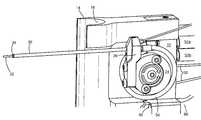
도 1은 본 발명의 실시예들에 따른 가요성 랜스의 일례를 도시하는 개략적인 3 차원 정면도이다.
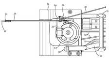
도 2는 도 1의 랜스 헤드를 도시하며, 여기서 튜브 레인 정렬 가이드는 인터 튜브 구역에서의 증기 발생기에서 튜브들의 하나의 열에서 1 튜브를 결합시키고 세정 워터 제트 강성 튜브가 튜브 레인에 배치된다.
도 3은 하나의 랜스 헤드와 연관된 주요 컴포넌트들을 도시하는 개략적인 측면도이다.
도 4는 하나의 랜스 헤드와 연관된 주요 컴포넌트들을 도시하는 개략적인 횡단 측면도이다.
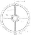
도 5는 회전 워터 제트들을 도시하는 개략도이다.
도 6은 회전 워터 제트 배럴을 도시하는 개략적인 횡단면도이다.
도 7은 제어기의 제어 하에 모터에 의해 구동되는 제트 배럴 드라이브 케이블을 도시하는 개략도이다.
도 8은 리니어 튜브 시트 워터 제트 속도가 도 7에 도시된 회전 배럴 및 노즐의 각 회전 속도(angular rotation rate)를 변화시킴으로써 어떻게 달성되는지를 나타내는 고도의 개략도이다.
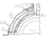
도 9는 증기 발생기의 인터 튜브 구역 및 NTL 레인에서의 관절식 가이드 레일을 도시하는 개략적인 평면도이다.
도 10은 가요성 랜스 헤드 및 다른 컴포넌트들을 도시하는 상세도이다.
도 11은 관절식 랜스 가이드 및 가요성 랜스 헤드를 도시하는 또다른 개략도이다.
도 12는 가요성 랜스 헤드 회전 유체 제트 조립체가 증기 발생기의 튜브 시트들 근처에서 튜브를 어떻게 세정할 수 있는지를 도시하는 개략적인 횡단면도이다.Other objects, features and advantages will occur to those skilled in the art from the following description of the preferred embodiments and the accompanying drawings.
1 is a schematic three-dimensional front view showing an example of a flexible lance according to embodiments of the present invention.
FIG. 2 shows the lance head of FIG. 1 wherein the tube lane alignment guide couples one tube in one row of tubes in a steam generator in an intertube compartment and a clean water jet rigid tube is disposed in the tube lane.
Figure 3 is a schematic side view showing the major components associated with one lance head.
Figure 4 is a schematic cross-sectional side view showing the major components associated with one lance head.
Figure 5 is a schematic diagram showing rotating water jets.
Figure 6 is a schematic cross-sectional view showing a rotating water jet barrel.
7 is a schematic diagram showing a jet barrel drive cable driven by a motor under the control of a controller.
Figure 8 is a high-level schematic diagram showing how the linear tube sheet water jet velocity is achieved by varying the angular rotation rate of the rotating barrel and nozzle shown in Figure 7;
Figure 9 is a schematic plan view showing an articulated guide rail in an NTL lane and an intertube section of a steam generator.
Figure 10 is a detail view showing a flexible lance head and other components.
11 is another schematic diagram showing the articulated lance guide and the flexible lance head.
Figure 12 is a schematic cross-sectional view showing how the flexible lance head rotating fluid jet assembly can clean the tubes near the tubesheets of the steam generator.
하기 개시된 바람직한 실시예 또는 실시예들 이외에, 본 발명은 다른 실시예들을 취하고 그리고, 다양한 방식들로 실시되거나 실행될 수 있다. 따라서, 본 발명이 도면들에서 예시되거나 하기 설명에서 제시된 컴포넌트들의 배열들 및 구성의 상세들로 본 발명의 적용에 있어서 제한되지 않는 것이 이해되어야 한다. 단지 하나의 실시예가 본원에서 설명된다면, 그 청구항들은 그 실시예로 제한되지 않는다. 더욱이, 그 청구항들은 소정의 배제, 제한 또는 포기를 나타내는 확실하고 입증된 증거가 없는 한, 제한적으로 판독되지 않는다.In addition to the preferred embodiments or embodiments described below, the present invention may take other embodiments and be practiced or carried out in various ways. It is, therefore, to be understood that the invention is not limited in its application to the details of construction and the arrangement of components illustrated in the drawings or set forth in the following description. If only one embodiment is described herein, then the claims are not limited to that embodiment. Moreover, the claims are not to be construed as limited unless there are reliable and proven evidence of any exclusion, restriction or waiver.
본 발명의 하나의 기능은 모델 CE80, OPR-1000 및 APR-1400 원자력 발전소들(Nuclear Power Plants) 및 다른 것들에서 알려진 것들과 같은, 제한적인 인터 튜브 갭들 및 억세스를 갖는 증기 발생기들의 인터 튜브 구역으로부터 경질 또는 연질 슬러지 퇴적물들(sludge deposits)을 분해하기 위한 수단을 제공하는 것이다.One function of the present invention is to extend the flow of steam from the intern tube section of the steam generators with limited intertube gaps and access, such as those known in the models CE80, OPR-1000 and APR-1400 Nuclear Power Plants and others. And to provide means for decomposing hard or soft sludge deposits.
상기 인용된 발전소들 모두, 즉 CE80, OPR-1000 및 APR-1400은 매우 작은 NTL 클리어런스와 3 mm 미만의 폭의 인터 튜브 갭들을 갖는 증기 발생기들을 사용한다. 제한된 NTL 및 중앙 구역 영역들로부터 작동하기에는 장비가 너무 크기 때문에, 작은 NTL 클리어런스는 전체 증기 발생기 인터 튜브 구역을 세정하기 위해 기존의 슬러지 랜싱 시스템의 사용을 배제한다. 기존의 모든 랜싱 기술들은 센터 돔/실린더 영역 둘레로부터 시작하여 예측 가능하고 효율적으로 인터 튜브 레인들의 세정을 해결하지 못한다. NTL로부터 환체(annulus)를 향해 인터 튜브 레인들을 세정하는 것은, 증기 발생기의 중앙 구역 근처에 로케이팅되는 경질/연질 슬러지에 스프레이들이 영향을 미치는 것을 허용하며, 환체 구역에서 시작하는 스프레잉보다 훨씬 큰 힘이 가해진다. 슬러지에 대한 노즐의 스탠드 오프(stand-off) 거리는 스프레이들의 힘을 최대화하기 위해서 가능한 한 짧다.All of the above cited power plants, namely CE80, OPR-1000 and APR-1400, use steam generators having very small NTL clearances and intertube gaps of width less than 3 mm. The small NTL clearance precludes the use of conventional sludge lancing systems to clean the entire steam generator intern tube area, since equipment is too large to operate from the limited NTL and central zone areas. All existing lancing techniques do not address the cleaning of intertube lanes predictably and efficiently, starting from the center dome / cylinder region periphery. Cleaning the intertube lanes from the NTL towards the annulus permits the spray to affect the hard / soft sludge locating near the central zone of the steam generator and is much larger than the spraying starting at the fissure zone The force is applied. The stand-off distance of the nozzle to the sludge is as short as possible to maximize the force of the spray.
일 양태에서, 본 발명은 모델 CE80, OPR-1000, APR-1400과 같은 매우 작은 튜브 갭들 및 센터 스테이(center stay) 돔/실린더를 갖는, NTL로부터의 접근이 매우 제한적인 증기 발생기 설계들을 위해 인터 튜브 고압 워터 세정을 제공할 필요를 해결한다. 본원에 설명된 시스템은 상기 증기 발생기들의 스테이 돔/실린더 둘레에서 시작하여 증기 발생기 환체 구역까지 연장하는 증기 발생기 인터 튜브 레인들에 접근한다.In one aspect, the present invention provides an interconnection structure for very accessible steam generator designs from the NTL with very small tube gaps and center stay dome / cylinder, such as models CE80, OPR-1000, APR- Solves the need to provide tube high pressure water cleaning. The system described herein approaches the steam generator intertubule lanes starting from around the stadium / cylinder of the steam generators to the steam generator loop section.
도 1 내지 도 6에 도시된 하나의 제안된 슬러지 랜싱 시스템은, 도 2에 도시된 중앙 구역 인터 튜브 레인들(102)에 접근하기 위한 요구를 해결하며 슬러지 제거를 위한 예측 가능한 수단을 제공한다. 제안된 슬러지 랜싱 시스템은 튜브들의 2 개의 열들 사이의 공간으로 규정되는 튜브 레인의 정면에 정확하게 포지셔닝될 수 있는 헤드(12)로 도 1의 가요성 랜스(10)를 정확하게 전달하기 위한 수단을 포함한다. 회전 배럴(20)은 강성 튜브에 의해 튜브 레인으로 안내되고 제어 가능한 리니어 튜브 시트 속도로 회전하는 고효율 노즐을 통해 탈염수(demineralized water)의 높은 압력 및 유동을 전달하며, 이 속도는 세정 워터 제트가 증기 발생기의 중심으로부터 외부 환체 구역으로 이동하는 것을 가능케 한다. 2 차 노즐은 회전 랜스 헤드에 결합될 수 있으며 그 목적은 세정 노즐에 대향하는 분사력(jetting force)을 제공하여 회전 헤드를 "제로 네트 분사력(zero net jetting force)"으로 안정시키는 것이다. 튜브 갭에 세정 노즐 제트를 중심에 두는 것이 세정 효율에 중요하다. 워터 제트 일관성(coherency)은 야외에서(open air) 이동하는 거리의 영향을 받는다. 워터 채널로서 야외가 아닌 워터 채널로서 역할을 하는 튜브 레인에 워터 제트가 진입하기 이전 거리가 짧을수록, 더 일관된 상태를 유지하고 파워가 더 클수록, 그 타겟 상에서 인터 튜브 슬러지를 전달한다. 선행 기술 시스템들은 튜브 레인 개구의 중앙에 정확히 노즐을 예측 가능하게 포지셔닝시키지 못하고, 그리고 이들의 스탠드오프 거리는 20 mm에서 수백 mm 사이에서 변한다. 강성 튜브에 의해 튜브 레인에 세척 제트 노즐을 포지셔닝시키면 이 개방 공기 튜브 갭이 제거된다. 게다가, (튜브 레인의 입구에서) 하사점(bottom dead center)과 스팀 발생기 환체 사이의 리니어 튜브 시트 속도로 회전하는 세정 제트는, 효과적으로 흡입될 수 있는 환체 구역으로 인터 튜브 슬러지를 이송하는데 중요할 수 있다. 선행 기술 시스템들이 주로 큰 스탠드오프 거리(standoff distance)로부터 분사하기 때문에, 워터 제트 일관성이 악화되고 주로 레인에 진입하는 것 대신에 제 1 튜브 표면들에 부딪치며, 그리고 이 시스템들이 효과적인 리니어 튜브 시트 속도를 제공하는 각 속도로 회전하지 않기 때문에, 이 시스템들은 언급된 증기 발생기들의 중앙 구역을 예측 가능하고 효율적으로 세정하지 못한다.One proposed sludge lancing system shown in Figures 1 to 6 solves the need to access the central
가요성 랜스는 바람직하게는, 랜스 가이드(11)로부터 연장하고 랜스 가이드(11) 내로 후퇴하며, 그리고 오목 튜브 정렬 가이드(14)를 갖는 헤드를 포함한다. 랜스 헤드는 또한 회전 유체 제트 조립체를 포함한다. 회전 배럴은 랜스 헤드에 대해 90° 회전하며 드라이브 케이블에 의해 구동될 수 있다.The flexible lance preferably includes a head extending from the
하나 또는 그 초과의 워터 라인들은 가요성 랜스에 의해 지지되고 물을 랜스 헤드 및 랜스 헤드에 고정된 피팅으로 전달한다. 가요성 급수 호스(water supply hose)는 일단부 상에서 랜스 헤드 핏팅에 연결되고 회전 배럴 주위를 부드럽게 구부러지며 루핑하여, 급수 호스가 회전 배럴에 고정된 피팅에 연결될 수 있다. 이로부터, 물(water)이 강성 튜브에 진입하며, 이 강성 튜브는 정렬 가이드를 넘어 증기 발생기의 인접 튜브들 사이의 갭으로 잘 연장한다. 강성 튜브의 단부에서 고효율 노즐이 존재한다. 강성 튜브는 스테인레스 강으로 만들어질 수 있다.One or more of the water lines are supported by the flexible lance and deliver water to the fittings fixed to the lance head and lance head. A water supply hose is connected to the lance head fitting on one end and gently bends and loops around the rotating barrel so that the water supply hose can be connected to the fitting fixed to the rotating barrel. From there, water enters the rigid tube, which extends well beyond the alignment guide into the gap between adjacent tubes of the steam generator. There is a high efficiency nozzle at the end of the rigid tube. Rigid tubes can be made of stainless steel.
이 구성은, 물이 이동해야 하는 턴들(turns) 및/또는 굴곡들(bends)을 감소시키고 강성 튜브가 회전되는 것을 여전히 허용하면서 세정을 위해 강성 튜브의 출구에서 충분한 수압을 제공한다. 회전 배럴이 회전함에 따라 공급 호스는 코일링하고(coils) 언코일링한다(uncoils).This arrangement reduces the turns and / or bends that the water must travel and provides sufficient water pressure at the outlet of the rigid tube for cleaning while still allowing the rigid tube to rotate. As the rotating barrel rotates, the supply hose coils and coils (uncoils).
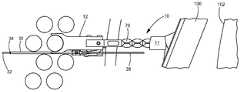
도 1은 관절식 가이드 레일에 의해 지지되는 관절식 랜스 가이드(11) 내의 가요성 랜스(10)의 예를 도시한다. 랜스(10)는 도 2의 중심 돔/실린더 영역(102)에 인접한 인터 튜브 구역에서 증기 발생기 내의 튜브들의 하나의 열에서 제 1 튜브와 맞물리기 위한 오목한 전면(16)을 갖는 튜브 정렬 가이드(14)를 갖는 헤드(12)를 포함한다.Figure 1 shows an example of a
도 2에 도시된 바와 같이 튜브들의 하나의 열에서 제 1 튜브(15)와 튜브들의 다른 열의 인접한 제 1 튜브(17) 사이에서, 인터 튜브 레인(13)의 중심에서 유체를 지향시키는 튜브 정렬 가이드에 인접한 회전 유체 제트 조립체(20)를 포함하도록 헤드(12)가 구성된다.Between the first tube (15) in one row of tubes and the adjacent first tube (17) in another row of tubes as shown in Figure 2, a tube alignment guide The
바람직한 일 실시예에서, 유체 제트 조립체(20)(도 1)는 베어링 등을 통해 고정구(22)에 대해 회전 가능한 랜스 헤드 고정구(22) 및 배럴(24)을 포함한다. 배럴(24)은 유체 피팅(26)을 포함한다. 튜브(30)는 가이드(14)의 전방으로 연장되고 말단 튜브 고효율 노즐(34)을 통해 유체(예컨대, 물) 세정 제트(32)를 생성하는 유체 피팅(26)에 연결된다. 피팅(26)은 또한 제트(32)에 의해 생성된 힘을 오프셋(offset)시키거나 상쇄(counterbalance)시키기 위해 세정 제트(32)에 대향하는 방향으로 세정 제트(38)를 생성하도록 포지셔닝되는 노즐(36)을 포함할 수 있다. 고정구(22)는 카메라/비디오 프로브(probe)(40)를 더 포함할 수 있다. 배럴(20) 상의 유체 피팅(26)은 오목한 표면(16) 바로 뒤에 포지셔닝되고 도시된 바와 같이 오프셋되어, 튜브(30)가 도 2에 도시된 바와 같이 증기 발생기 내의 튜브들 사이의 폭이 좁은 2.9 mm 갭 사이에 배치될 수 있다. 가이드(14)는 튜브(30)가 오목한 표면(16)의 전방으로 진행하는 것을 허용하도록 내측으로 변위된 측벽(17)을 포함한다.In one preferred embodiment, the fluid jet assembly 20 (FIG. 1) includes a
고정구(22)에 대해 배럴(24)을 회전시키기 위해, 케이블(50)은 도시된 바와 같이 랜스(10)를 통해 연장하여 배럴(20) 주위를 연결한다. 하나 또는 그 초과의 유체 공급 라인들(52a, 52b)은 또한 랜스(10) 내로 연장하고 유체 고정구(22)에 연결된다. 가요성 유체 공급 호스는 유체 피팅(26)에 대해 일단부에 연결되고, 고정구(22)에 대해 타단부 상에 연결되며, 유체 공급 라인(들)으로부터 튜브(30) 및 노즐(34)로 유체를 전달하기 위해 도시된 바와 같이 배럴(20) 주위에서 루핑한다. 비디오/카메라 케이블(60)은 또한 랜스(10) 내에서 파워 프로브(40)까지 연장하고 랜스를 통해 이미지들을 전송한다.To rotate the
도 3에 도시된 바와 같이, 랜스(10)는 바람직하게는, 케이블(50), 라인들(52), 프로브 케이블(60), 및 선택적인 프로브 퍼지(purge) 도관(72)을 통해 수용하도록 구성된 개별적인 관절식 세그먼트들(70a, 70b, 70) 등을 포함한다.3,
도 4는, 고정구(22)에 대해 배럴(24)을 회전시키고 피팅(26)을 회전시키는데 사용되는 케이블(50)에 대한 채널들(80a 및 80b)을 내부에 갖는 랜스 헤드 고정구(22)의 내부를 도시한다. 랜스 헤드 고정구(22)의 내부는, 또한 공급 라인(들)(52)과 호스(54) 사이의 유체 연결부들(84) 및 카운터밸런싱 제트(38)를 제공하는 피팅 노즐을 포함한다. 랜스 안전 케이블들(86a, 86b)이 또한 제공될 수 있다. 도 5 및 도 6은 또한 회전 유체 제트 조립체의 양태들을 도시한다. 도 7은 제어기(51)의 제어 하에 모터(M)에 의해 구동되는 배럴 구동 케이블을 도시한다. 바람직하게는, 제어기는 리니어 증기 발생기 튜브 시트 유체 제트 속도를 달성하기 위해 가변 회전 속도로 케이블을 통해 회전 가능한 배럴을 회전시키도록 모터(M)를 제어하도록 구성(예컨대, 프로그래밍)된다. 즉, 도 8에 도시된 바와 같이 튜브 시트에 충돌하는 제트 스프레이는 예컨대, 50 mm/초의 일정한 속도로 튜브 시트를 가로질러 진행한다.Figure 4 shows a side view of the
제안된 슬러지 랜싱 시스템은 도 9 내지 도 12의 "NTL(No Tube Lane)"(100) 및 증기 발생기(104)의 중앙 구역(102) 양자 모두로부터 작동할 수 있다. 시스템은 관절식 랜스 가이드(111) 및 회전 스프레이 헤드를 수용하는 가요성 랜스(10)를 지지할 일시적으로 설치되는 관절식 가이드 레일(106)을 포함할 수 있다. 랜스 가이드는 튜브 갭 개구의 앞쪽에 랜스 헤드를 정밀하게 포지셔닝시키기 위해 엔코더 피드백(encoder feedback)이 장비된 전기 모터의 사용을 통해 레일을 따라 전기적으로 이동시키는 수단을 포함한다. 정확한 랜스 헤드 스탠드 오프 거리 포지셔닝을 위해 엔코더 피드백이 장비된 전기 모터를 사용하여 튜브 레인에서 제 1 튜브로부터 연장하고 수축하는 가요성 랜스를 구동하는 수단을 포함할 수 있다. 랜스 헤드는 회전 랜스 헤드 워터 제트를 튜브 레인의 중심에 정확히 포지셔닝시키기 위해 제 1 튜브 곡률(curvature)의 절반을 결합시키는 오목한 수단을 포함한다. 세정 워터 분사 강성 튜브 및 노즐은, 그 다음에, 노즐 아래의 튜브 시트에 물을 분무하도록 회전하고 환체가 도달될 때까지 튜브 시트에서 물을 분무하도록 회전한다. 더욱이, 랜스 헤드 튜브 곡률 결합 컴포넌트는 도 1의 센서(108)를 포함할 수 있으며, 이는 제 1 튜브와 만곡된 랜스 헤드 결합 컴포넌트 사이의 거리를 측정하며 이는 시스템 조작자 및/또는 자동화된 컴퓨터 동작들이 제 1 튜브 레인 튜브에 대해 강하게 푸시하는 것을 방지할 수 있게 한다. 회전 가능한 배럴은 그의 회전에 영향을 미치는 수단을 포함하며, 이는 인터 튜브 제팅 노즐이 그의 하사점 중심 포지션 사이에서 수평 90° 포지션으로 회전한다. 노즐 회전은 회전 헤드 외경 상의 2 개의 대향 지점들을 기계적으로 연결하고, 회전 드럼이 장비된 전기 모터에 연결되는 고강도 금속 및/또는 Kevlar와 같은 고강도 재료들의 케이블을 사용하거나 리니어 모터의 사용을 통해 제어된다. 일단 하나의 인터 튜브 레인이 세정된다면, 랜스 헤드는 다른 인터 튜브 레인을 세정하기 위해 리포지셔닝된다.The proposed sludge lancing system can operate from both the "NTL (No Tube Lane)" 100 of FIGS. 9-12 and the
도 7 및 도 8의 회전 가능한 랜스 헤드 모터(M)는, 워터 제트의 리니어 튜브 시트 속도를 생성하는 회전을 행하도록 프로그래밍되는 제어기(51)를 통해 제어될 수 있다. 대안의 실시예는, 랜스 헤드가 튜브 갭에서 정확하게 정렬된 후에 튜브 레인에 물리적으로 진입하기에 충분히 긴 연장 가능한 또는 고정된 노즐을 포함하며, 입수 가능한 모든 워터 제트가 단락된(shorted) 스탠드오프 거리에서 슬러지 파일(sludge pile)로 지향되는 것을 보장한다.The rotatable lance head motor M of Figs. 7 and 8 can be controlled through a
랜스 헤드는 시각적 피드백을 위해 조작자가 사용하는 비디오 프로브 또는 카메라 및 라이트 파이프를 포함할 수 있다.The lance head may include a video probe or camera and a light pipe used by an operator for visual feedback.
매우 짧은 스탠드오프 거리로부터 또는 워터 제트 세정 효율성을 최대화하는 튜브 레인 내부로부터 워터 제트를 분사하는, 증기 발생기 튜브 레인 개구 - 특히 CE80, OPR-1000 및 APR-1400 유형들의 중앙 구역에서 - 전방에서 회전 노즐 하우징을 예측 가능하고 그리고 정확하게 포지셔닝시킬 수 있는 제어 가능한 가요성 랜스 헤드를 특징으로 한다.In the central zone of the steam generator tube lane openings - particularly the CE80, OPR-1000 and APR-1400 types, which eject water jets from very short standoff distances or from within the tube lanes to maximize water jet cleaning efficiency - And a controllable flexible lance head capable of positioning the housing in a predictable and precise manner.
또 다른 특징은 심지어 튜브 시트 슬러지 제거를 위해 전체 튜브 레인 길이의 균일한 스윕(even sweep)에 영향을 미치는 리니어 튜브 시트 워터 제트 속도의 도입이다. 또 다른 특징은 튜브 레인 전방의 가요성 랜스 헤드 상에서 제어 가능하고 정밀한 포지셔닝을 가능하게 하는 관절식 랜스 가이드의 도입이다. 여전히, 또 다른 특징은 세정 제트와 일치하는 대향 제트 노즐의 도입에 의해 영향을 받는 랜스 헤드의 "제로 네트 분사력 설계"이다.Another feature is the introduction of a linear tube seat water jet velocity that even sweeps the entire tube lane length for tube seat sludge removal. Another feature is the introduction of an articulated lance guide that allows controllable and precise positioning on the flexible lance head in front of the tube lane. Still another feature is the "zero net injection force design" of the lance head that is affected by the introduction of the opposing jet nozzles in agreement with the cleaning jet.
본 발명의 소정의 특징들이 일부 도면들에 도시되어 있고 다른 도면들에 도시되지는 않았지만, 이는 단지 각 특징이 본 발명에 따른 임의의 또는 모든 다른 특징들과 결합될 수 있기 때문에 단지 편의상 제시된다. 본원에서 사용된 바와 같이 "포함하는", "구비하는", "갖는” 및 "가진"이라는 단어들은 광범위하게 그리고 포괄적으로 해석되어야 하며 그리고 임의의 물리적인 상호연결로 제한되지 않는다. 또한, 본 출원에 개시된 임의의 실시예들은 유일한 가능한 실시예들로서 간주되어서는 안된다. 다른 실시예들은 당업자에게 자명하며 다음의 청구항들 내에 있다.While certain features of the invention are shown in some drawings and not in others, it is only presented for convenience only as each feature may be combined with any or all of the other features in accordance with the invention. As used herein, the terms "comprising," "having," "having," and "having" are to be interpreted broadly and inclusively and are not limited to any physical interconnections. Should not be construed as the only possible embodiments. Other embodiments are obvious to those of ordinary skill in the art and are within the following claims.
게다가, 이 특허에 대한 특허 출원의 기소 중 제출된 임의의 보정안은 출원된 출원에 제시된 임의의 청구항 요소의 포기는 아니며: 당업자는 문자 그대로 모든 가능한 등가물들을 포함하는 청구항을 드래프트하는 것이 합리적으로 기대될 수 없고, 많은 등가물들은 보정시에 예측할 수 없으며 포기될(존재한다면) 것이 무엇인지에 대한 공정한 해석을 넘어서고 있으며, 보정의 근거가 되는 이론적 근거는 많은 등가물들과 별로 관계가 없는 관계를 맺을 뿐이며, 그리고/또는 출원인이 임의의 보정된 청구항 요소에 대한 비실체적인 대체물들을 설명할 것으로 예상될 수 없는 많은 다른 이유들이 존재한다.In addition, any amendment submitted during the prosecution of a patent application for this patent is not a waiver of any claim element recited in the filed application: a person of ordinary skill in the art would reasonably be expected to draft a claim comprising literally all possible equivalents Many equivalents are beyond the fair interpretation of what can be unpredicted and abandoned (if present) at the time of correction, and the rationale on which the correction is based only has a relationship that is not related to many equivalents, And / or there are many other reasons why the applicant can not be expected to account for non-realistic alternatives to any calibrated claim element.
Claims (30)
Translated fromKorean관절식 랜스 가이드(articulating lance guide);
상기 관절식 랜스 가이드를 지지하며 상기 증기 발생기 중심 구역 인터 튜브 레인(inter-tube lane)에 근접하게 상기 관절식 랜스 가이드를 포지셔닝시키는 증기 발생기 NTL(no tube lane)에 배치되는 관절식 가이드 레일(rail); 및
상기 관절식 랜스 가이드 내부로부터 연장 가능한 가요성 랜스(lance)를 포함하며, 상기 가요성 랜스는,
센터 돔(dome)/실린더 영역에 인접한 인터 튜브 구역에서 상기 증기 발생기 내의 튜브의 하나의 열에서 제 1 튜브와 맞물리기 위한 오목한 표면을 포함하는 튜브 레인 정렬 가이드를 갖는 헤드(head), 및
상기 튜브의 하나의 열의 제 1 튜브와 상기 튜브의 다른 열의 인접한 제 1 튜브 사이의 인터 튜브 레인의 중심에 유체를 지향시키기 위해 상기 튜브 레인 정렬 가이드에 인접한 회전 유체 제트(jet) 조립체를 포함하는,
증기 발생기 세정 시스템.In a steam generator cleaning system,
An articulating lance guide;
An articulated guide rail (not shown) disposed in a steam generator NTL (no tube lane) that supports the articulated lance guide and positions the articulated lance guide proximate the steam generator central section inter- ); And
And a flexible lance extending from the inside of the articulated lance guide,
A head having a tube lane alignment guide including a concave surface for engaging the first tube in one row of tubes in the steam generator in an intertube region adjacent a center dome /
And a rotating fluid jet assembly adjacent the tube lane alignment guide for directing fluid to a center of an intertube lane between a first tube of one row of the tube and an adjacent first tube of another row of the tube.
Steam generator cleaning system.
상기 유체 제트의 분사력(jetting force)을 오프셋하도록 포지셔닝되는 상기 회전 유체 제트 조립체 상에 노즐(nozzle)을 더 포함하는,
증기 발생기 세정 시스템.The method according to claim 1,
Further comprising a nozzle on the rotating fluid jet assembly being positioned to offset a jetting force of the fluid jet.
Steam generator cleaning system.
상기 랜스 헤드는 고정구(fixture)를 포함하고, 상기 회전 유체 제트 조립체는 상기 고정구에 대해 회전 가능한 배럴(barrel)을 포함하고, 유체 피팅(fluid fitting)이 상기 배럴 상에 포함되는,
증기 발생기 세정 시스템.The method according to claim 1,
Wherein the lance head includes a fixture and the rotating fluid jet assembly includes a barrel rotatable relative to the fixture and a fluid fitting is included on the barrel,
Steam generator cleaning system.
상기 가요성 랜스 및 상기 랜스 헤드 고정구를 통해 연장하고 상기 회전 가능한 배럴에 연결되는 드라이브 케이블(drive cable)을 더 포함하는,
증기 발생기 세정 시스템.The method of claim 3,
Further comprising a drive cable extending through the flexible lance and the lance head fastener and connected to the rotatable barrel.
Steam generator cleaning system.
상기 케이블은 모터에 의해 제어되는,
증기 발생기 세정 시스템.5. The method of claim 4,
Said cable being controlled by a motor,
Steam generator cleaning system.
리니어(linear) 증기 발생기 튜브 시트 유체 제트 속도를 달성하기 위해 가변 회전 속도(variable rate of rotation)로 상기 드라이브 케이블을 통해 상기 회전 가능한 배럴을 회전시키게 상기 모터를 제어하도록 구성된 제어기를 더 포함하는,
증기 발생기 세정 시스템.6. The method of claim 5,
Further comprising a controller configured to control the motor to rotate the rotatable barrel through the drive cable at a variable rate of rotation to achieve a linear steam generator tube seat fluid jet velocity,
Steam generator cleaning system.
상기 랜스 헤드 고정구에 대해 일단부 상에 연결되고, 상기 유체 피팅에 대해 반대편 단부 상에 연결되며, 상기 회전 가능한 배럴 주위를 루핑하는(looping) 가요성 유체 공급 호스(hose)가 존재하는,
증기 발생기 세정 시스템.The method of claim 3,
A flexible fluid supply hose connected on one end to the lance head fixture and connected on the opposite end to the fluid fitting and looping around the rotatable barrel,
Steam generator cleaning system.
상기 가요성 랜스를 통해 연장하고 상기 랜스 헤드 고정구에 연결되는 유체 공급 라인을 더 포함하는,
증기 발생기 세정 시스템.8. The method of claim 7,
Further comprising a fluid supply line extending through the flexible lance and connected to the lance head fixture,
Steam generator cleaning system.
상기 가요성 유체 공급 라인으로부터 유체를 수용하는 상기 유체 피팅에 연결되는 강성(rigid) 튜브를 더 포함하는,
증기 발생기 세정 시스템.8. The method of claim 7,
And a rigid tube coupled to the fluid fitting for receiving fluid from the flexible fluid supply line.
Steam generator cleaning system.
상기 강성 튜브의 말단 단부에 노즐을 더 포함하는,
증기 발생기 세정 시스템.10. The method of claim 9,
Further comprising a nozzle at a distal end of the rigid tube,
Steam generator cleaning system.
상기 배럴 상의 상기 유체 피팅은 카운터밸런싱 워터 제트(counterbalancing water jet)를 생성하는 후방 노즐을 포함하는,
증기 발생기 세정 시스템.The method of claim 3,
Wherein the fluid fitting on the barrel includes a rear nozzle that produces a counterbalancing water jet.
Steam generator cleaning system.
상기 고정구 상의 프로브(probe) 및 상기 가요성 랜스를 통해 연장하는 프로브 케이블(probe cable)을 더 포함하는,
증기 발생기 세정 시스템.The method of claim 3,
Further comprising a probe on the fixture and a probe cable extending through the flexible lance.
Steam generator cleaning system.
센터 돔/실린더 영역에 인접한 인터 튜브 구역에서 상기 증기 발생기 내의 튜브의 하나의 열에서 제 1 튜브와 맞물리기 위한 오목한 표면을 포함하는 튜브 레인 정렬 가이드를 갖는 헤드, 및
상기 튜브의 하나의 열의 제 1 튜브와 상기 튜브의 다른 열의 인접한 제 1 튜브 사이의 인터 튜브 레인의 중심에 유체를 지향시키기 위해 상기 튜브 레인 정렬 가이드에 인접한 회전 유체 제트 조립체를 포함하는,
증기 발생기 세정 가요성 랜스.In a steam generator cleaning flexible lance,
A head having a tube lane alignment guide including a concave surface for engaging the first tube in one row of tubes in the steam generator in an intertube region adjacent the center dome /
And a rotating fluid jet assembly adjacent the tube lane alignment guide for directing fluid to a center of an intertube lane between a first tube of one row of the tube and an adjacent first tube of another row of the tube.
Steam Generator Cleaning Flexible Lance.
상기 유체 제트의 분사력을 오프셋하도록 포지셔닝되는 상기 회전 유체 제트 조립체 상에 노즐을 더 포함하는,
증기 발생기 세정 가요성 랜스.14. The method of claim 13,
Further comprising a nozzle on the rotating fluid jet assembly being positioned to offset the jetting force of the fluid jet.
Steam Generator Cleaning Flexible Lance.
상기 랜스 헤드는 고정구를 포함하고, 상기 회전 유체 제트 조립체는 상기 고정구에 대해 회전 가능한 배럴을 포함하고, 유체 피팅이 상기 배럴 상에 포함되는,
증기 발생기 세정 가요성 랜스.14. The method of claim 13,
Wherein the lance head includes a fixture, the rotatable fluid jet assembly including a barrel rotatable with respect to the fixture, and wherein a fluid fitting is included on the barrel,
Steam Generator Cleaning Flexible Lance.
상기 가요성 랜스 및 상기 랜스 헤드 고정구를 통해 연장하고 상기 회전 가능한 배럴에 연결되는 드라이브 케이블을 더 포함하는,
증기 발생기 세정 가요성 랜스.16. The method of claim 15,
And a drive cable extending through the flexible lance and the lance head fastener and connected to the rotatable barrel.
Steam Generator Cleaning Flexible Lance.
상기 케이블은 모터에 의해 제어되는,
증기 발생기 세정 가요성 랜스.17. The method of claim 16,
Said cable being controlled by a motor,
Steam Generator Cleaning Flexible Lance.
리니어(linear) 증기 발생기 튜브 시트 유체 제트 속도를 달성하기 위해 가변 회전 속도(variable rate of rotation)로 상기 드라이브 케이블을 통해 상기 회전 가능한 배럴을 회전시키게 상기 모터를 제어하도록 구성된 제어기를 더 포함하는,
증기 발생기 세정 가요성 랜스.18. The method of claim 17,
Further comprising a controller configured to control the motor to rotate the rotatable barrel through the drive cable at a variable rate of rotation to achieve a linear steam generator tube seat fluid jet velocity,
Steam Generator Cleaning Flexible Lance.
상기 랜스 헤드 고정구에 대해 일단부 상에 연결되고, 상기 유체 피팅에 대해 반대편 단부 상에 연결되며, 회전 가능한 배럴 주위를 루핑하는(looping) 가요성 유체 공급 호스가 존재하는,
증기 발생기 세정 가요성 랜스.16. The method of claim 15,
A flexible fluid supply hose connected on one end to the lance head fixture and connected on the opposite end to the fluid fitting and looping around the rotatable barrel,
Steam Generator Cleaning Flexible Lance.
상기 가요성 유체 공급 호스로부터 유체를 수용하는 상기 유체 피팅에 연결되는 강성 튜브를 더 포함하는,
증기 발생기 세정 가요성 랜스.20. The method of claim 19,
And a rigid tube connected to the fluid fitting for receiving fluid from the flexible fluid supply hose.
Steam Generator Cleaning Flexible Lance.
상기 랜스 내에서 연장하고 상기 고정구에 연결되는 유체 공급 라인을 더 포함하는,
증기 발생기 세정 가요성 랜스.21. The method of claim 20,
Further comprising a fluid supply line extending within said lance and connected to said fixture,
Steam Generator Cleaning Flexible Lance.
상기 강성 튜브의 말단 단부에 노즐을 더 포함하는,
증기 발생기 세정 가요성 랜스.22. The method of claim 21,
Further comprising a nozzle at a distal end of the rigid tube,
Steam Generator Cleaning Flexible Lance.
상기 배럴 상의 상기 유체 피팅은 카운터밸런싱 워터 제트를 제공하는 후방 노즐을 포함하는,
증기 발생기 세정 가요성 랜스.16. The method of claim 15,
Wherein the fluid fitting on the barrel includes a rear nozzle that provides a counterbalanced water jet.
Steam Generator Cleaning Flexible Lance.
상기 고정구 상의 프로브(probe) 및 상기 가요성 랜스를 통해 연장하는 프로브 케이블(probe cable)을 더 포함하는,
증기 발생기 세정 가요성 랜스.16. The method of claim 15,
Further comprising a probe on the fixture and a probe cable extending through the flexible lance.
Steam Generator Cleaning Flexible Lance.
센터 돔/실린더 영역에 인접한 인터 튜브 구역에서 상기 증기 발생기 내의 튜브의 하나의 열에서 제 1 튜브와 맞물리기 위한 오목한 표면을 포함하는 튜브 레인 정렬 가이드를 갖는 헤드, 및
상기 가이드 뒤에 있는 헤드 상의 고정구;
상기 고정구 상의 회전 유체 제트 배럴; 및
상기 튜브들 사이에 세정 유체 제트를 지향시키기 위한 상기 배럴 상의 유체 피팅을 포함하는,
증기 발생기 세정 가요성 랜스.In a steam generator cleaning flexible lance,
A head having a tube lane alignment guide including a concave surface for engaging the first tube in one row of tubes in the steam generator in an intertube region adjacent the center dome /
A fastener on the head behind the guide;
A rotating fluid jet barrel on said fixture; And
And a fluid fitting on said barrel for directing a cleaning fluid jet between said tubes.
Steam Generator Cleaning Flexible Lance.
상기 유체 제트의 분사력을 오프셋하도록 포지셔닝되는 상기 유체 피팅 상의 노즐을 더 포함하는,
증기 발생기 세정 가요성 랜스.26. The method of claim 25,
Further comprising a nozzle on the fluid fitting positioned to offset the jetting force of the fluid jet.
Steam Generator Cleaning Flexible Lance.
상기 가요성 랜스 및 상기 랜스 헤드 고정구를 통해 연장하고 상기 회전 가능한 배럴에 연결되는 드라이브 케이블을 더 포함하는,
증기 발생기 세정 가요성 랜스.26. The method of claim 25,
And a drive cable extending through the flexible lance and the lance head fastener and connected to the rotatable barrel.
Steam Generator Cleaning Flexible Lance.
상기 랜스 헤드 고정구에 대해 일단부 상에 연결되고, 상기 유체 피팅에 대해 반대편 단부 상에 연결되며, 회전 가능한 배럴 주위를 루핑하는 가요성 유체 공급 호스가 존재하는,
증기 발생기 세정 가요성 랜스.26. The method of claim 25,
A flexible fluid supply hose connected on one end to the lance head fixture and connected on the opposite end to the fluid fitting, the flexible fluid supply hose looping around a rotatable barrel,
Steam Generator Cleaning Flexible Lance.
상기 가요성 유체 공급 라인으로부터 유체를 수용하는 상기 유체 피팅에 연결되는 강성 튜브를 더 포함하는,
증기 발생기 세정 가요성 랜스.29. The method of claim 28,
Further comprising a rigid tube coupled to the fluid fitting for receiving fluid from the flexible fluid supply line.
Steam Generator Cleaning Flexible Lance.
상기 랜스 내에서 연장하고 상기 고정구에 연결되는 유체 공급 라인을 더 포함하는,
증기 발생기 세정 가요성 랜스.30. The method of claim 29,
Further comprising a fluid supply line extending within said lance and connected to said fixture,
Steam Generator Cleaning Flexible Lance.
Applications Claiming Priority (3)
| Application Number | Priority Date | Filing Date | Title |
|---|---|---|---|
| US201462062277P | 2014-10-10 | 2014-10-10 | |
| US62/062,277 | 2014-10-10 | ||
| PCT/US2015/054469WO2016057653A1 (en) | 2014-10-10 | 2015-10-07 | Rotating lance head steam generator lancing system |
Publications (2)
| Publication Number | Publication Date |
|---|---|
| KR20170066627Atrue KR20170066627A (en) | 2017-06-14 |
| KR101989020B1 KR101989020B1 (en) | 2019-06-13 |
Family
ID=55653715
Family Applications (1)
| Application Number | Title | Priority Date | Filing Date |
|---|---|---|---|
| KR1020177012649AActiveKR101989020B1 (en) | 2014-10-10 | 2015-10-07 | Rotating lance head steam generator lancing system |
Country Status (2)
| Country | Link |
|---|---|
| KR (1) | KR101989020B1 (en) |
| WO (1) | WO2016057653A1 (en) |
Families Citing this family (3)
| Publication number | Priority date | Publication date | Assignee | Title |
|---|---|---|---|---|
| CN109433704B (en)* | 2018-12-21 | 2024-02-09 | 核动力运行研究所 | Steam generator flushing gun with inter-pipe positioning compensation structure |
| RU2752975C1 (en)* | 2020-09-23 | 2021-08-11 | Акционерное Общество "Российский Концерн По Производству Электрической И Тепловой Энергии На Атомных Станциях" (Ао "Концерн Росэнергоатом") | Apparatus for cleaning heat exchange pipes of steam generator of atomic power plant with high pressure water jets |
| CN112474625B (en)* | 2020-11-27 | 2022-06-17 | 长飞光纤光缆股份有限公司 | Quartz tube stick peripheral face self-cleaning device |
Citations (4)
| Publication number | Priority date | Publication date | Assignee | Title |
|---|---|---|---|---|
| US5572957A (en)* | 1994-02-01 | 1996-11-12 | The Babcock & Wilcox Company | Automated sludge lance |
| US5913320A (en)* | 1995-04-11 | 1999-06-22 | Foster-Miller, Inc. | Sludge removal system |
| US20080092924A1 (en)* | 2006-06-30 | 2008-04-24 | Jean Collin | Low-pressure sludge removal method and apparatus using coherent jet nozzles |
| US20090211612A1 (en)* | 2008-01-08 | 2009-08-27 | Christos Athanassiu | Super-thin water jetting lance |
Family Cites Families (3)
| Publication number | Priority date | Publication date | Assignee | Title |
|---|---|---|---|---|
| US5411043A (en)* | 1993-09-24 | 1995-05-02 | The Babcock & Wilcox Company | Articulated annular sludge lance |
| US8238510B2 (en)* | 2007-07-03 | 2012-08-07 | Westinghouse Electric Company Llc | Steam generator dual head sludge lance and process lancing system |
| US8646416B2 (en)* | 2009-11-03 | 2014-02-11 | Westinghouse Electric Company Llc | Miniature sludge lance apparatus |
- 2015
- 2015-10-07KRKR1020177012649Apatent/KR101989020B1/enactiveActive
- 2015-10-07WOPCT/US2015/054469patent/WO2016057653A1/enactiveApplication Filing
Patent Citations (4)
| Publication number | Priority date | Publication date | Assignee | Title |
|---|---|---|---|---|
| US5572957A (en)* | 1994-02-01 | 1996-11-12 | The Babcock & Wilcox Company | Automated sludge lance |
| US5913320A (en)* | 1995-04-11 | 1999-06-22 | Foster-Miller, Inc. | Sludge removal system |
| US20080092924A1 (en)* | 2006-06-30 | 2008-04-24 | Jean Collin | Low-pressure sludge removal method and apparatus using coherent jet nozzles |
| US20090211612A1 (en)* | 2008-01-08 | 2009-08-27 | Christos Athanassiu | Super-thin water jetting lance |
Also Published As
| Publication number | Publication date |
|---|---|
| WO2016057653A1 (en) | 2016-04-14 |
| KR101989020B1 (en) | 2019-06-13 |
Similar Documents
| Publication | Publication Date | Title |
|---|---|---|
| USRE38542E1 (en) | Upper bundle steam generator cleaning system and method | |
| KR101989020B1 (en) | Rotating lance head steam generator lancing system | |
| US6820575B2 (en) | Upper bundle steam generator cleaning, inspection, and repair system | |
| US5036871A (en) | Flexible lance and drive system | |
| CA2115109C (en) | Automated sludge lance | |
| US5782209A (en) | Segmented automated sludge lance | |
| KR102159558B1 (en) | the robot for washing ring shape space of korean steam generator | |
| US7086353B2 (en) | Lance system for inter-tube inspecting and lancing as well as barrel spraying of heat transfer tubes of steam generator in nuclear power plant | |
| JPS58117999A (en) | Extraneous-matter removing device for heat exchanger, etc. and its method | |
| RU2692748C2 (en) | Appliance and method for cleaning heat exchanger inner zone | |
| CN103261788B (en) | Guides for flexible spray guns | |
| KR20210103534A (en) | Systems and methods for cleaning heat exchanger tubes | |
| CN105423807B (en) | The equipment for guiding the shell of guide device and cleaning equipped with access aperture of flexible spray gun | |
| US20020108644A1 (en) | Steerable delivery system | |
| US7497224B2 (en) | Nozzle apparatus | |
| KR100363297B1 (en) | An upper bundle steam generator cleaning, inspection, and repair system | |
| KR100708889B1 (en) | Nuclear Power Plant Steam Generator Cleaning Equipment Using High Pressure Water Injection | |
| US20150027499A1 (en) | Multi-angle sludge lance | |
| WO2021063465A1 (en) | Method and apparatus for cleaning boiler surfaces in an incineration plant | |
| KR101734601B1 (en) | Miniature sludge lance apparatus | |
| KR100563936B1 (en) | High pressure water jet steam generator sludge cleaning equipment | |
| RU2343336C2 (en) | Pipelines inspection device containing centered head | |
| ES2317384T3 (en) | CONICAL SEAT VALVE OF SMALL LOSSES AND CLEANING FLUID SUPPLY PROCEDURE WITH THE SAME. | |
| CN209393673U (en) | Steam generator cleaning device | |
| ES2749798T3 (en) | Device and method for high pressure cleaning of the tubes of a heat exchanger |
Legal Events
| Date | Code | Title | Description |
|---|---|---|---|
| A201 | Request for examination | ||
| PA0105 | International application | Patent event date:20170510 Patent event code:PA01051R01D Comment text:International Patent Application | |
| PA0201 | Request for examination | ||
| PG1501 | Laying open of application | ||
| E902 | Notification of reason for refusal | ||
| PE0902 | Notice of grounds for rejection | Comment text:Notification of reason for refusal Patent event date:20180330 Patent event code:PE09021S01D | |
| AMND | Amendment | ||
| E601 | Decision to refuse application | ||
| PE0601 | Decision on rejection of patent | Patent event date:20190131 Comment text:Decision to Refuse Application Patent event code:PE06012S01D Patent event date:20180330 Comment text:Notification of reason for refusal Patent event code:PE06011S01I | |
| AMND | Amendment | ||
| PX0901 | Re-examination | Patent event code:PX09011S01I Patent event date:20190131 Comment text:Decision to Refuse Application Patent event code:PX09012R01I Patent event date:20180829 Comment text:Amendment to Specification, etc. | |
| PX0701 | Decision of registration after re-examination | Patent event date:20190521 Comment text:Decision to Grant Registration Patent event code:PX07013S01D Patent event date:20190429 Comment text:Amendment to Specification, etc. Patent event code:PX07012R01I Patent event date:20190131 Comment text:Decision to Refuse Application Patent event code:PX07011S01I Patent event date:20180829 Comment text:Amendment to Specification, etc. Patent event code:PX07012R01I | |
| X701 | Decision to grant (after re-examination) | ||
| PR0701 | Registration of establishment | Comment text:Registration of Establishment Patent event date:20190607 Patent event code:PR07011E01D | |
| PR1002 | Payment of registration fee | Payment date:20190607 End annual number:3 Start annual number:1 | |
| PG1601 | Publication of registration | ||
| PR1001 | Payment of annual fee | Payment date:20220617 Start annual number:4 End annual number:4 | |
| PR1001 | Payment of annual fee | Payment date:20230515 Start annual number:5 End annual number:5 | |
| PR1001 | Payment of annual fee | Payment date:20240422 Start annual number:6 End annual number:6 |