KR20170065574A - Cradle and portable electronic apparatus set - Google Patents
Cradle and portable electronic apparatus setDownload PDFInfo
- Publication number
- KR20170065574A KR20170065574AKR1020177011039AKR20177011039AKR20170065574AKR 20170065574 AKR20170065574 AKR 20170065574AKR 1020177011039 AKR1020177011039 AKR 1020177011039AKR 20177011039 AKR20177011039 AKR 20177011039AKR 20170065574 AKR20170065574 AKR 20170065574A
- Authority
- KR
- South Korea
- Prior art keywords
- electronic device
- portable electronic
- connector
- cradle
- cover
- Prior art date
- Legal status (The legal status is an assumption and is not a legal conclusion. Google has not performed a legal analysis and makes no representation as to the accuracy of the status listed.)
- Granted
Links
- 238000000034methodMethods0.000claimsdescription7
- 238000010586diagramMethods0.000description4
- 239000000470constituentSubstances0.000description3
- 230000001681protective effectEffects0.000description3
- 238000013459approachMethods0.000description2
- 230000005540biological transmissionEffects0.000description1
- 230000006835compressionEffects0.000description1
- 238000007906compressionMethods0.000description1
- 230000000994depressogenic effectEffects0.000description1
- 238000007689inspectionMethods0.000description1
- 238000012986modificationMethods0.000description1
- 230000004048modificationEffects0.000description1
Images


Classifications
- H—ELECTRICITY
- H02—GENERATION; CONVERSION OR DISTRIBUTION OF ELECTRIC POWER
- H02J—CIRCUIT ARRANGEMENTS OR SYSTEMS FOR SUPPLYING OR DISTRIBUTING ELECTRIC POWER; SYSTEMS FOR STORING ELECTRIC ENERGY
- H02J7/00—Circuit arrangements for charging or depolarising batteries or for supplying loads from batteries
- H02J7/0042—Circuit arrangements for charging or depolarising batteries or for supplying loads from batteries characterised by the mechanical construction
- H—ELECTRICITY
- H04—ELECTRIC COMMUNICATION TECHNIQUE
- H04M—TELEPHONIC COMMUNICATION
- H04M1/00—Substation equipment, e.g. for use by subscribers
- H04M1/02—Constructional features of telephone sets
- H04M1/11—Supports for sets, e.g. incorporating armrests
Landscapes
- Engineering & Computer Science (AREA)
- Signal Processing (AREA)
- Power Engineering (AREA)
- Telephone Set Structure (AREA)
- Charge And Discharge Circuits For Batteries Or The Like (AREA)
Abstract
Translated fromKorean
Description
Translated fromKorean본 발명은 휴대형 전자 기기가 장착되는 크레이들, 및 휴대형 전자 기기와 크레이들을 구비하는 휴대형 전자 기기 세트에 관한 것이다.The present invention relates to a cradle on which a portable electronic device is mounted, and a portable electronic device set including the portable electronic device and the cradle.
종래, 검품에 사용되는 HHT 단말기(Hand Held Terminal), 태블릿 단말기, 스마트폰 등의 휴대형 전자 기기에는, 커넥터를 덮는 방수 캡 등의 커넥터 커버가 설치된다.2. Description of the Related Art Conventionally, a portable electronic device such as an HHT terminal (Hand Held Terminal), a tablet terminal, or a smart phone used for inspection has a connector cover such as a waterproof cap covering a connector.
일례이기는 하지만, 커넥터 커버는, 커넥터를 덮는 커버 본체와, 이 커버 본체에 연결되고 휴대형 전자 기기의 내부에 발출 가능하게 수용되는 아암부를 갖는다. 이러한 커넥터 커버에서는, 휴대형 전자 기기가 크레이들에 장착될 때, 커버 본체는, 미리 사람의 손에 의해 커넥터를 덮는 위치로부터 벗겨져서 현수된 상태로 된다. 또한, 현수된 상태의 커버 본체는, 휴대형 전자 기기가 크레이들에 장착되는 것을 방해하지 않는 위치에 사람의 손으로 보유 지지된다.As an example, the connector cover has a cover body covering the connector, and an arm portion connected to the cover body and being retractably received in the interior of the portable electronic device. In such a connector cover, when the portable electronic device is mounted on the cradle, the cover body comes off from the position where the cover is covered by the human hand in advance and is in a suspended state. Further, the cover body in the suspended state is held by a human hand in a position where it does not prevent the portable electronic device from being mounted on the cradle.
여기서, 크레이들은, 장착되는 휴대형 전자 기기에 대하여 데이터 송수신, 충전 등의 어떤 처리를 행하기 위한 커넥터를 갖는 기기이다.Here, the cradle is a device having a connector for performing a certain process such as data transmission / reception, charging, etc. with respect to a portable electronic device to be mounted.
다른 커넥터 커버의 예인데, 커넥터 커버가 휴대형 전자 기기에 대하여 분리 가능하게 설치되어 있는 경우에는, 미리 사람의 손에 의해 휴대형 전자 기기로부터 벗겨진 커넥터 커버를 분실하지 않도록, 사람이 보관해야 한다는 수고가 발생한다. 또한, 애당초 커넥터 커버가 설치되어 있지 않은 경우에는, 커넥터가 항상 외부에 노출되기 때문에, 커넥터에 쇼트, 파손 등의 문제가 발생할 수 있다.In the case where the connector cover is detachably attached to the portable electronic device, there is a problem that a person has to store the connector cover so that the connector cover peeled off from the portable electronic device is not lost by the hand of a person in advance do. In addition, if the connector cover is not installed initially, the connector is always exposed to the outside, which may cause problems such as short-circuiting and breakage of the connector.
그런데, 휴대형 전자 기기의 커넥터와 크레이들의 커넥터를 접속하기 위한 구조로서, 크레이들의 커넥터를 덮는 보호 가이드가, 휴대형 전자 기기의 커넥터를 덮는 보호 커버의 경사면부를 누름으로써, 이 보호 커버를 개방시키는 구조가 알려져 있다(예를 들어, 특허문헌 1 참조).As a structure for connecting the connector of the portable electronic device and the connector of the cradle, there is a structure in which the protection guide covering the connector of the cradle opens the protection cover by pressing the inclined face portion of the protection cover covering the connector of the portable electronic device (See, for example, Patent Document 1).
또한, 탄성력에 저항하여 휴대형 전자 기기의 개구부에 끼워 넣어져 있는 커버부가, 개구부로부터 개방된 경우에 개구부의 바로 아래보다도 후방의 개방 위치로 복귀되는 구조가 알려져 있다(예를 들어, 특허문헌 2 참조).Further, there is known a structure in which, when the cover portion is opened from the opening portion, the cover portion, which is fitted in the opening portion of the portable electronic device against the elastic force, is returned to the open position rearward of the opening portion directly below (see, for example, Patent Document 2 ).
그러나, 상술한 바와 같이, 크레이들의 보호 가이드가 휴대형 전자 기기의 보호 커버의 경사면부를 누름으로써, 이 보호 커버를 개방시키는 구조는, 눌리는 측의 보호 커버를 개폐시키는 기구가 휴대형 전자 기기에 설치되게 된다. 그로 인해, 휴대형 전자 기기의 구조가 복잡화된다.However, as described above, in the structure for opening the protective cover by pressing the inclined surface portion of the protective cover of the portable electronic device, the mechanism for opening and closing the protective cover on the depressed side is installed in the portable electronic device . As a result, the structure of the portable electronic device becomes complicated.
또한, 상술한 바와 같이, 휴대형 전자 기기의 개구부에 끼워 넣어져 있었던 커버부가, 개구부로부터 개방된 경우에 개구부의 바로 아래보다도 후방의 개방 위치로 복귀되는 구조는, 개방 시의 커버부를 개방 위치로 복귀시키는 기구가 휴대형 전자 기기에 설치되게 된다. 그로 인해, 휴대형 전자 기기의 구조가 복잡화된다.As described above, in the structure in which the cover portion, which has been inserted into the opening portion of the portable electronic device, is returned to the opening position behind the opening portion immediately below the opening portion when the cover portion is opened from the opening portion, The portable electronic device is installed in the apparatus. As a result, the structure of the portable electronic device becomes complicated.
본 발명의 목적은, 휴대형 전자 기기의 구조가 복잡화되는 것을 방지하면서, 크레이들에 대한 휴대형 전자 기기의 장착 경로로부터 휴대형 전자 기기의 커넥터 커버를 확실하게 퇴피시킬 수 있는 크레이들 및 휴대형 전자 기기 세트를 제공할 수 있다.An object of the present invention is to provide a cradle and a portable electronic device set capable of reliably retracting a connector cover of a portable electronic device from a mounting path of a portable electronic device to a cradle while preventing the structure of the portable electronic device from being complicated .
하나의 형태에서는, 크레이들은, 전자 기기 커넥터와 그 전자 기기 커넥터를 덮는 커넥터 커버를 구비하는 휴대형 전자 기기가 장착되는 크레이들이며, 상기 전자 기기 커넥터에 접속되는 크레이들 커넥터를 갖고, 상기 휴대형 전자 기기를 보유 지지하는 보유 지지부와, 상기 크레이들에 대한 상기 휴대형 전자 기기의 장착 경로를 차폐하는 제1 위치에 있어서, 상기 휴대형 전자 기기에 의해 가압됨으로써, 상기 커넥터 커버를 걸어서 수용하면서, 상기 장착 경로로부터 퇴피한 제2 위치로 이동하는 걸림부를 구비한다.In one form, the cradles are cradles mounted with a portable electronic device having an electronic device connector and a connector cover covering the electronic device connector, and having a cradle connector connected to the electronic device connector, Wherein the connector cover is pushed by the portable electronic device in a first position for shielding the mounting path of the portable electronic device with respect to the cradle, And an engaging portion that moves to a second position.
다른 하나의 형태에서는, 휴대형 전자 기기 세트는, 전자 기기 커넥터와 그 전자 기기 커넥터를 덮는 커넥터 커버를 구비하는 휴대형 전자 기기와, 상기 휴대형 전자 기기가 장착되는 크레이들을 구비하는 휴대형 전자 기기 세트이며, 상기 크레이들은, 상기 전자 기기 커넥터에 접속되는 크레이들 커넥터를 갖고, 상기 휴대형 전자 기기를 보유 지지하는 보유 지지부와, 상기 크레이들에 대한 상기 휴대형 전자 기기의 장착 경로를 차폐하는 제1 위치에 있어서, 상기 휴대형 전자 기기에 의해 가압됨으로써, 상기 커넥터 커버를 걸어서 수용하면서, 상기 장착 경로로부터 퇴피한 제2 위치로 이동하는 걸림부와, 상기 걸림부를 상기 제1 위치를 향하여 부세(付勢)하는 부세부를 구비한다.In another form, the portable electronic device set is a portable electronic device having a portable electronic device having an electronic device connector and a connector cover covering the electronic device connector, and a cradle on which the portable electronic device is mounted, A cradle having a cradle connector connected to the electronic device connector, the cradle comprising: a holding portion for holding the portable electronic device; and a second position for shielding the mounting path of the portable electronic device with respect to the cradle, A latching portion which is pressed by the portable electronic device to move the connector cover from the mounting path to a retracted second position while accommodating the connector cover, and a sub-portion which urges the latching portion toward the first position Respectively.
본 발명에 따르면, 휴대형 전자 기기의 구조가 복잡화되는 것을 방지하면서, 크레이들에 대한 휴대형 전자 기기의 장착 경로로부터 휴대형 전자 기기의 커넥터 커버를 확실하게 퇴피시킬 수 있다.According to the present invention, the connector cover of the portable electronic device can reliably be retracted from the mounting path of the portable electronic device with respect to the cradle while preventing the structure of the portable electronic device from being complicated.
도 1은 본 발명의 일 실시 형태에 따른 휴대형 전자 기기 세트를 도시하는 사시도이다.
도 2a는 본 발명의 일 실시 형태에 있어서의 걸림부를 도시하는 정면도이다.
도 2b는 본 발명의 일 실시 형태에 있어서의 걸림부 및 판 스프링을 도시하는 우측면도이다.
도 2c는 본 발명의 일 실시 형태에 있어서의 걸림부 및 판 스프링을 도시하는 배면도이다.
도 2d는 본 발명의 일 실시 형태에 있어서의 걸림부 및 판 스프링을 우경사 후방으로부터 본 사시도이다.
도 2e는 본 발명의 일 실시 형태에 있어서의 걸림부 및 판 스프링을 좌경사 후방으로부터 본 사시도이다.
도 3a는 본 발명의 일 실시 형태에 있어서의, 전자 기기 커넥터와 크레이들 커넥터가 접속될 때의 걸림부의 동작을 설명하기 위한 설명도(그 1)이다.
도 3b는 본 발명의 일 실시 형태에 있어서의, 전자 기기 커넥터와 크레이들 커넥터가 접속될 때의 걸림부의 동작을 설명하기 위한 설명도(그 2)이다.
도 3c는 본 발명의 일 실시 형태에 있어서의, 전자 기기 커넥터와 크레이들 커넥터가 접속될 때의 걸림부의 동작을 설명하기 위한 설명도(그 3)이다.1 is a perspective view showing a portable electronic device set according to an embodiment of the present invention.
FIG. 2A is a front view showing a latching portion in an embodiment of the present invention. FIG.
FIG. 2B is a right side view showing the latching portion and the leaf spring in one embodiment of the present invention. FIG.
2C is a rear view showing the latching portion and the leaf spring according to the embodiment of the present invention.
FIG. 2D is a perspective view of the latching portion and the leaf spring according to the embodiment of the present invention as viewed from the rear of the right tilted portion. FIG.
Fig. 2E is a perspective view of the latching portion and the leaf spring according to one embodiment of the present invention, as viewed from the rearward of the left inclination. Fig.
FIG. 3A is an explanatory diagram (part 1) for explaining the operation of the engagement portion when the electronic device connector and the cradle connector are connected in the embodiment of the present invention. FIG.
3B is an explanatory diagram (No. 2) for explaining the operation of the engagement portion when the electronic device connector and the cradle connector are connected in the embodiment of the present invention.
3C is an explanatory diagram (No. 3) for explaining the operation of the engagement portion when the electronic device connector and the cradle connector are connected in the embodiment of the present invention.
이하, 본 발명의 실시 형태에 따른 크레이들 및 휴대형 전자 기기 세트에 대해서, 도면을 참조하면서 설명한다.Hereinafter, a cradle and a portable electronic device set according to an embodiment of the present invention will be described with reference to the drawings.
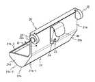
도 1은, 본 발명의 일 실시 형태에 따른 휴대형 전자 기기 세트(100)를 도시하는 사시도이다.1 is a perspective view showing a portable electronic device set 100 according to an embodiment of the present invention.
도 1에 도시되는 휴대형 전자 기기 세트(100)는 크레이들(1) 및 파선으로 나타내지는 휴대형 전자 기기 세트(100)를 구비한다.The portable electronic device set 100 shown in FIG. 1 includes a
휴대형 전자 기기(101)는 크레이들(1)에 장착되는 예를 들어 HHT 단말기이지만, 태블릿 단말기, 스마트폰, 또는 기타의 휴대형 전자 기기여도 된다.The portable
후술하는 도 3a 내지 도 3c에 주로 파선(은선)으로 나타낸 바와 같이, 휴대형 전자 기기(101)는 전자 기기 커넥터(110)와, 이 전자 기기 커넥터(110)를 덮는 커넥터 커버(120)를 구비한다.3A to 3C, the portable
커넥터 커버(120)는 예를 들어 방수 캡이다. 커넥터 커버(120)는 전자 기기 커넥터(110)를 덮는 커버 본체(121)와, 이 커버 본체(121)에 연결되어 휴대형 전자 기기(101)의 내부에 발출 가능하게 수용되는 막대상의 아암부(122)를 갖는다.The
도 1에 도시되는 크레이들(1)은 보유 지지부(10)와, 걸림부(20)와, 부세부의 일례인 판 스프링(30)(도 2b 내지 도 2e 참조)과, 기기 수용부(40)를 구비한다.The
보유 지지부(10)는 보유 지지부 본체(11)와, 크레이들 커넥터(12)와, 가이드부(13, 14)와, 리브(15, 16)와, 지지 패드(17, 18)를 갖고, 휴대형 전자 기기(101)를 보유 지지한다.The
보유 지지부 본체(11)는 크레이들(1)에 장착된 휴대형 전자 기기(101)의 각각 후방, 하방, 전방에 위치하는, 후면부(11a), 하면부(11b), 및 전면부(11c)를 포함한다. 전면부(11c)는 후면부(11a)와 비교하여 높이가 낮기 때문에, 보유 지지부 본체(11)는 우측면에서 보아 J자 형상을 나타낸다.The
크레이들 커넥터(12)는 보유 지지부 본체(11)의 하면부(11b)로부터 상방으로 돌출되도록 설치되어 있다. 크레이들 커넥터(12)는 휴대형 전자 기기(101)의 전자 기기 커넥터(110)에 접속된다.The
가이드부(13, 14)는, 크레이들(1)에 장착되는 과정의 휴대형 전자 기기(101)의 양측면의 각각을 가이드한다. 가이드부(13, 14)는, 보유 지지부 본체(11)의 후면부(11a)의 좌우 양단에 형성되어 있다.The
좌측의 가이드부(13)는 후면부(11a)의 좌측 단부로부터 좌방향으로 돌출되고, 굴곡되어 전방향으로 연장되고, 다시 굴곡되어 우방향으로 연장되는 플레이트이다. 우측의 가이드부(14)는 후면부(11a)의 우측 단부로부터 우방향으로 돌출되고, 굴곡되어 전(前)방향으로 연장하고, 다시 굴곡되어 좌방향으로 연장되는 플레이트이다.The
가이드부(13, 14)는, 후면부(11a)에 대하여 복수의 끼워 넣는 위치 중 어느 하나에 있어서 끼워 넣어짐으로써, 서로의 간격이 조정 가능해도 된다.The
리브(15, 16)는, 보유 지지부 본체(11)의 후면부(11a)에 있어서의 하부의 좌우 2개소에 있어서, 후면부(11a)로부터 전방으로 돌출된다. 리브(15, 16)는, 휴대형 전자 기기(101)의 배면에 접촉함으로써 휴대형 전자 기기(101)를 지지한다.The
지지 패드(17, 18)는, 후면부(11a)의 좌측 상단 코너부 및 우측 상단 코너부의 2개소에 있어서, 후면부(11a)로부터 전방으로 돌출된 부분에 설치되어 있다. 지지 패드(17, 18)는, 휴대형 전자 기기(101)의 배면에 접촉함으로써 휴대형 전자 기기(101)를 지지한다.The
기기 수용부(40)는 보유 지지부(10)에 있어서의 하부의 후방에 배치되고, 휴대형 전자 기기(101)와의 데이터 송수신 등의 각종 처리를 행하는 제어부나, 배터리 등을 수용한다. 또한, 크레이들(1)이 휴대형 전자 기기(101)의 충전만을 행하는 경우에는, 기기 수용부(40)는 생략 가능하다.The
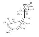
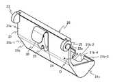
도 2a 내지 도 2e는, 본 발명의 일 실시 형태에 있어서의 걸림부(20) 및 판 스프링(30)을 도시하는 정면도, 우측면도, 배면도, 우경사 후방으로부터 본 사시도, 및 좌경사 후방으로부터 본 사시도이다. 또한, 도 2a에 있어서는, 판 스프링(30)은 걸림부(20)에 가려져서 도시되지 않는다.Figs. 2A to 2E are a front view, a right side view, a rear view, a perspective view seen from the rear of the right tilted portion, and a left tilted rear view showing the
걸림부(20)는 걸림부 본체(21)와, 플랜지부(22, 23)와, 고정 나사(24)와, 회동 규제용 돌기(25)를 갖는다.The engaging
걸림부 본체(21)는 아암 플레이트부(21a)와, 수용부(21b)와, 좌우의 측벽(21c, 21d)이 예를 들어 일체로 형성되어 있다.The latching unit
도 2b, 도 2d, 및 도 2e에 도시된 바와 같이, 아암 플레이트부(21a)는 평면 상을 나타내고, 도 1에 도시되는 보유 지지부 본체(11)의 후면부(11a)의 중앙에 있어서, 후면부(11a)와 평행하게 배치된다. 아암 플레이트부(21a)는 회동 중심축 부재로서 기능하는 후술하는 돌출부(23a, 23b)(플랜지부(22, 23))와 수용부(21b)를 직접적(간접적이어도 됨)으로 연결하는 아암부의 일례로서 기능한다.As shown in Figs. 2B, 2D, and 2E, the
도 2b, 도 2d, 및 도 2e에 도시된 바와 같이, 수용부(21b)는, 아암 플레이트부(21a)의 하단으로부터 굴곡되어 전방 비스듬히 하방으로 연장되는 제1 부분(21b-1)과, 이 제1 부분(21b-1)의 선단으로부터 만곡되어 전방 비스듬히 상방으로 연장하는 제2 부분(21b-2)과, 이 제2 부분(21b-2)으로부터 굴곡되어 상방으로 연장하는 제3 부분(21b-3)을 포함한다. 상세는 후술하겠지만, 도 3a 내지 도 3c에 도시된 바와 같이, 수용부(21b)는, 커넥터 커버(120)를 걸어서 수용한다.2B, 2D, and 2E, the
도 2a 및 도 2e에 도시된 바와 같이, 수용부(21b)에는, 제3 부분(21b-3)의 상단으로부터 제2 부분(21b-2)에 걸쳐서 절결부(21b-4)가 형성되어 있다. 이 절결부(21b-4)는, 도 2a에 도시된 바와 같이, 수용부(21b)의 좌우 방향의 중앙보다도 좌측으로 치우쳐 형성되어 있다.2A and 2E, a
도 2d 및 도 2e에 도시된 바와 같이, 측벽(21c, 21d)은, 수용부(21b)의 좌우 양단에 있어서 서로 대향하도록 형성되어 있다.As shown in Figs. 2D and 2E, the
도 2d 및 도 2e에 도시된 바와 같이, 플랜지부(22, 23)는, 아암 플레이트부(21a)의 좌측 상단 코너부 및 우측 상단 코너부의 2개소에 있어서, 아암 플레이트부(21a)로부터 후방으로 돌출되도록 형성되어 있다. 플랜지부(22, 23)는, 좌측면에서 보아, 그리고 도 2b의 우측면에서 보아 원형을 나타내는 원판 형상으로 형성되어 있다. 좌측의 플랜지부(22)에는, 좌 방향으로 돌출되는 돌출부(22a)가 형성되어 있다. 우측의 플랜지부(23)에는, 우 방향으로 돌출되는 돌출부(23a)가 형성되어 있다.2D and 2E, the
돌출부(22a, 23a)는, 도 1에 도시하는 보유 지지부 본체(11)의 후면부(11a)에 의해 회동 가능하게 지지되어 있다. 이에 의해, 걸림부(20)는 도 2b, 도 2d, 및 도 2e에 도시하는 화살표 D 방향으로 회동한다.The
도 2b, 도 2d, 및 도 2e에 도시된 바와 같이, 고정 나사(24)는 판 스프링(30)을 아암 플레이트부(21a)의 배면에 고정한다. 회동 규제용 돌기(25)는 아암 플레이트부(21a)의 배면으로부터 후방으로 돌출되도록 형성되어 있다. 회전 규제용 돌기(25)는 판 스프링(30)의 하단에 형성된 절결 부분에 감합됨으로써 판 스프링(30)의 회동을 규제한다.As shown in Figs. 2B, 2D and 2E, the fixing
판 스프링(30)은 아암 플레이트부(21a)와 도 1에 도시되는 보유 지지부 본체(11)의 후면부(11a)를 따르도록 상단측에서 만곡되어 있다. 판 스프링(30)은 보유 지지부(10)와 걸림부(20) 사이에 배치됨으로써, 걸림부(20)를 후술하는 도 3a에 도시하는 제1 위치 P1을 향하여 부세(bias)한다. 또한, 본 실시 형태에서는, 부세부의 일례가 판 스프링(30)이지만, 부세부로서는, 예를 들어, 비틀림 스프링, 압축 스프링, 고무와 같은 다른 탄성체 등이어도 된다.The
이하, 주로 걸림부(20)의 동작을 중심으로, 크레이들(1) 및 휴대형 전자 기기 세트(100)의 동작을 설명한다.Hereinafter, the operation of the
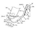
도 3a 내지 도 3c는, 본 발명의 일 실시 형태에 있어서의, 전자 기기 커넥터(110)와 크레이들 커넥터(12)가 접속될 때의 걸림부(20)의 동작을 설명하기 위한 설명도이다.3A to 3C are explanatory diagrams for explaining the operation of the
걸림부(20)는 휴대형 전자 기기(101)가 장착되어 있지 않은 상태에서는, 판 스프링(30)에 의해 부세됨으로써 도 3a에 도시하는 제1 위치 P1에 위치한다. 이 제1 위치 P1은, 걸림부(20)가 크레이들(1)에 대한 휴대형 전자 기기(101)의 장착 경로를 차폐하는 위치이다. 또한, 걸림부(20)의 적어도 일부가, 크레이들(1)에 장착되는 과정의 휴대형 전자 기기(101)와 크레이들 커넥터(12) 사이에 위치하면, 휴대형 전자 기기(101)의 장착 경로를 차폐한다고 할 수 있다.The latching
도 3a에 도시하는 휴대형 전자 기기(101)의 커넥터 커버(120)는 미리 사람의 손에 의해, 전자 기기 커넥터(110)를 덮는 위치로부터 커버 본체(121)가 벗겨지고, 아암부(122)가 휴대형 전자 기기(101)의 내부로부터 발출되어 있다. 이에 의해, 커버 본체(121)는 휴대형 전자 기기(101)로부터 현수된 상태, 즉, 전자 기기 커넥터(110)를 덮는 위치로부터 이격된 상태로 되어 있다.The
단, 커버 본체(121)는 전자 기기 커넥터(110)를 덮는 위치에 있어도 된다. 그 경우, 걸림부(20)가 후술하는 바와 같이 커버 본체(121)를 걺으로써 커버 본체(121)를 전자 기기 커넥터(110)를 덮는 위치로부터 이격시키면 된다.However, the cover
도 3a 및 도 3b에 도시된 바와 같이, 휴대형 전자 기기(101)는 크레이들(1)에 장착되는 과정에서, 제1 위치 P1에 있는 걸림부(20)를 가압하면서 크레이들 커넥터(12)에 접근한다. 예를 들어, 휴대형 전자 기기(101)는 걸림부(20)의 걸림부 본체(21)의 측벽(21c, 21d)에 있어서의 상단을 가압한다.As shown in FIGS. 3A and 3B, in the process of being mounted on the
걸림부(20)는 휴대형 전자 기기(101)에 의해 가압됨으로써, 커넥터 커버(120)를 걸어서 수용하면서, 판 스프링(30)의 탄성력에 저항하여 도 3b에 있어서의 반시계 방향(화살표 D1)으로 후방으로 회동한다. 예를 들어, 걸림부(20)는 걸림부 본체(21)의 수용부(21b)의 제3 부분(21b-3)에 있어서 커넥터 커버(120)의 커버 본체(121)를 걸고, 수용부(21b) 내에 수용한다.The engaging
그리고, 도 3b 및 도 3c에 도시된 바와 같이, 휴대형 전자 기기(101)가 크레이들 커넥터(12)에 더 접근하고, 전자 기기 커넥터(110)와 크레이들 커넥터(12)가 접속되면, 걸림부(20)는 커넥터 커버(120)를 걸어서 수용하면서, 휴대형 전자 기기(101)의 장착 경로로부터 퇴피한 제2 위치 P2로 이동한다.When the portable
이 걸림부(20)의 제1 위치 P1으로부터 제2 위치 P2로의 이동 중에 있어서, 커버 본체(121)는 걸림부(20)의 회동에 수반하여 수용부(21b)에 수용된 채, 수용부(21b)의 제2 부분(21b-2)에 의해 들어올려져서 아래위가 반대로 되도록 반전된다. 그리고, 아암부(122)가 수용부(21b)의 절결부(21b-4)에 삽입되고, 절결부(21b-4)에 의해 지지된다.The cover
그 후, 휴대형 전자 기기(101)가 크레이들(1)로부터 취출될 때에는, 걸림부(20)는 휴대형 전자 기기(101)에 의해 가압되지 않게 된다. 그로 인해, 걸림부(20)는 판 스프링(30)으로부터 가해지는 부세력에 의해, 도 3a에 도시하는 제1 위치 P1로 복귀하도록 회동한다.Thereafter, when the portable
또한, 본 실시 형태에서는, 걸림부(20)는 회동함으로써 제1 위치 P1과 제2 위치 P2로 이동하는데, 예를 들어 슬라이드함으로써 제1 위치 P1과 제2 위치 P2로 이동해도 된다. 그 경우의 걸림부(20)의 일례로서는, 제1 위치 P1에 있어서 휴대형 전자 기기(101)에 의해 가압됨으로써 커넥터 커버(120)를 걸어서 수용하면서 제2 위치 P2로 슬라이드하는 슬라이더와, 이 슬라이더를 가이드하는 가이드를 갖는 걸림부를 들 수 있다.In the present embodiment, the latching
이상 설명한 본 실시 형태에서는, 크레이들(1)에는, 전자 기기 커넥터(110)와, 이 전자 기기 커넥터(110)를 덮는 커넥터 커버(120)를 구비하는 휴대형 전자 기기(101)가 장착된다. 보유 지지부(10)는 휴대형 전자 기기(101)의 전자 기기 커넥터(110)에 접속되는 크레이들 커넥터(12)를 갖고, 휴대형 전자 기기(101)를 보유 지지한다. 걸림부(20)는 크레이들(1)에 대한 휴대형 전자 기기(101)의 장착 경로를 차폐하는 제1 위치 P1에 있어서, 휴대형 전자 기기(101)에 의해 가압됨으로써, 커넥터 커버(120)를 걸어서 수용하면서, 장착 경로로부터 퇴피한 제2 위치 P2로 이동한다. 부세부의 일례인 판 스프링(30)은 걸림부(20)를 제1 위치 P1을 향하여 부세한다.The portable
그로 인해, 휴대형 전자 기기(101)측의 구조가 아니라, 걸림부(20) 및 판 스프링(30)을 사용한, 크레이들(1)측의 구조에 의해, 휴대형 전자 기기(101)의 커넥터 커버(120)를 장착 경로로부터 퇴피시킬 수 있다. 또한, 걸림부(20)가 커넥터 커버(120)를 걸어서 수용하면서 제2 위치 P2로 이동하기 때문에, 커넥터 커버(120)를 확실하게 장착 경로로부터 퇴피시킬 수 있다.The structure of the
따라서, 본 실시 형태에 의하면, 휴대형 전자 기기(101)의 구조가 복잡화되는 것을 방지하면서, 크레이들(1)에 대한 휴대형 전자 기기(101)의 장착 경로로부터 휴대형 전자 기기(101)의 커넥터 커버(120)를 확실하게 퇴피시킬 수 있다. 이에 의해, 휴대형 전자 기기(101)가 크레이들(1)에 장착되는 때에 커넥터 커버(120)를 사람의 손으로 보유 지지하는 수고를 생략할 수 있다. 그로 인해, 전자 기기 커넥터(110)와 크레이들 커넥터(12)의 접속 부분을 주시하면서 휴대형 전자 기기(101)를 크레이들(1)에 장착할 수도 있다. 또한, 걸림부(20)는 판 스프링(30)에 의해 제1 위치 P1을 향하여 부세되고 있기 때문에, 휴대형 전자 기기(101)가 장착되지 않는 상태에서는, 제1 위치 P1인, 휴대형 전자 기기(101)의 장착 경로를 차폐하는 위치에 있어서 크레이들 커넥터(12)를 보호할 수도 있다.Therefore, according to the present embodiment, it is possible to prevent the structure of the portable
또한, 본 실시 형태에서는, 걸림부(20)는 전자 기기 커넥터(110)를 덮는 위치로부터 이격된 상태의 커넥터 커버(120)를 걸어서 수용하면서 제2 위치 P2로 이동한다. 그로 인해, 보다 한층 확실하게, 휴대형 전자 기기(101)의 커넥터 커버(120)를 장착 경로로부터 퇴피시킬 수 있다.In this embodiment, the engaging
또한, 본 실시 형태에서는, 걸림부(20)는 보유 지지부(10)에 의해 제1 위치 P1과 제2 위치 P2에 회동 가능하게 지지되어 있다. 그로 인해, 걸림부(20)를 이동시키기 위한 구조를 간소하게 할 수 있다.In this embodiment, the latching
또한, 본 실시 형태에서는, 부세부가, 걸림부(20)와 보유 지지부(10) 사이에 배치된 판 스프링(30)이다. 그로 인해, 걸림부(20)를 이동시키기 위한 구조를 보다 한층 간소하게 할 수 있다.Further, in the present embodiment, the sub-details are the
또한, 본 실시 형태에서는, 휴대형 전자 기기(101)의 커넥터 커버(120)는 전자 기기 커넥터(110)를 덮는 커버 본체(121)와, 이 커버 본체(121)에 연결되고 휴대형 전자 기기(101)의 내부에 발출 가능하게 수용되는 아암부(122)를 갖는다. 걸림부(20)에는, 커버 본체(121)를 걸어서 수용한 상태에서, 아암부(122)가 삽입되는 절결부(21b-4)가 형성되어 있다. 그로 인해, 수용부(21b)가 커버 본체(121)를 수용하기 쉬워지는 것에 의해, 보다 한층 확실하게, 휴대형 전자 기기(101)의 커넥터 커버(120)를 장착 경로로부터 퇴피시킬 수 있다.The
또한, 본 실시 형태에서는, 보유 지지부(10)는 크레이들(1)에 장착되는 과정의 휴대형 전자 기기(101)의 양측면의 각각을 가이드하는 2개의 가이드부(13, 14)를 더 구비한다. 그로 인해, 휴대형 전자 기기(101)의 장착 경로가 규정되어, 휴대형 전자 기기(101)가 걸림부(20)를 가압하기 쉬워진다. 이에 의해, 보다 한층 확실하게, 휴대형 전자 기기(101)의 커넥터 커버(120)를 장착 경로로부터 퇴피시킬 수 있다.In the present embodiment, the holding
또한, 본 발명은 상술한 실시 형태 그대로 한정되는 것은 아니며, 실시 단계에서의 그 요지를 일탈하지 않는 범위에서 구성 요소를 변형하여 구체화할 수 있다. 또한, 실시 형태에 개시되어 있는 복수의 구성 요소의 적당한 조합에 의해, 여러가지 발명을 형성할 수 있다. 예를 들어, 실시 형태에 나타내는 전체 구성 요소를 적절히 조합해도 된다. 이와 같이, 발명의 취지를 일탈하지 않는 범위 내에 있어서 다양한 변형이나 응용이 가능한 것은 물론이다.The present invention is not limited to the above-described embodiments, and can be embodied by modifying the constituent elements without departing from the gist of the embodiment. In addition, various inventions can be formed by appropriately combining a plurality of constituent elements disclosed in the embodiments. For example, all the constituent elements shown in the embodiment may be appropriately combined. It goes without saying that various modifications and applications are possible within the scope not departing from the gist of the invention.
1: 크레이들
10: 보유 지지부
11: 보유 지지부 본체
11a: 후면부
11b: 하면부
11c: 전면부
12: 크레이들 커넥터
13, 14: 가이드부
15, 16: 리브
17, 18: 지지 패드
20: 걸림부
21: 걸림부 본체
21a: 아암 플레이트부
21b: 수용부
21b-1: 제1 부분
21b-2: 제2 부분
21b-3: 제3 부분
21b-4: 절결부
21c, 21d: 측벽
22: 플랜지부
22a: 돌출부
23: 플랜지부
23a: 돌출부
24: 고정 나사
25: 회동 규제용 돌기
30: 판 스프링
40: 기기 수용부
100: 휴대형 전자 기기 세트
101: 휴대형 전자 기기
110: 전자 기기 커넥터
120: 커넥터 커버
121: 커버 본체
122: 아암부1: Cradle
10:
11:
11a:
11b:
11c: front portion
12: Cradle connector
13, 14: guide portion
15, 16: rib
17, 18: support pads
20:
21:
21a: arm plate portion
21b:
21b-1: first part
21b-2: second part
21b-3: Third part
21b-4:
21c, 21d: side wall
22: flange portion
22a:
23: flange portion
23a:
24: Securing screw
25: rotation restricting projection
30: leaf spring
40:
100: Portable electronic device set
101: Portable electronic devices
110: Electronic connector
120: Connector cover
121: Cover body
122:
Claims (7)
Translated fromKorean상기 전자 기기 커넥터에 접속되는 크레이들 커넥터를 갖고, 상기 휴대형 전자 기기를 보유 지지하는 보유 지지부와,
상기 크레이들에 대한 상기 휴대형 전자 기기의 장착 경로를 차폐하는 제1 위치에 있어서, 상기 휴대형 전자 기기에 의해 가압됨으로써, 상기 커넥터 커버를 걸어서 수용하면서, 상기 장착 경로로부터 퇴피한 제2 위치로 이동하는 걸림부
를 구비하는 것을 특징으로 하는 크레이들.A cradle in which a portable electronic device having an electronic device connector and a connector cover covering the electronic device connector is mounted,
A holding portion having a cradle connector connected to the electronic device connector and holding the portable electronic device;
Wherein the connector cover is pressed by the portable electronic device at a first position for shielding the mounting path of the portable electronic device with respect to the cradle so as to move from the mounting path to a retracted second position [0030]
And a cradle.
상기 걸림부에는, 상기 커버 본체를 걸어서 수용한 상태에서, 상기 아암부가 삽입되는 절결부가 형성되어 있는,
것을 특징으로 하는 크레이들.2. The portable electronic device according to claim 1, wherein the connector cover of the portable electronic device has a cover body covering the electronic device connector, and an arm portion connected to the cover body,
Wherein the engaging portion is provided with a cutout portion into which the arm portion is inserted in a state of being accommodated with the cover body being hooked,
A cradle characterized by:
상기 휴대형 전자 기기가 장착되는 크레이들
을 구비하는 휴대형 전자 기기 세트로서,
상기 크레이들은,
상기 전자 기기 커넥터에 접속되는 크레이들 커넥터를 갖고, 상기 휴대형 전자 기기를 보유 지지하는 보유 지지부와,
상기 크레이들에 대한 상기 휴대형 전자 기기의 장착 경로를 차폐하는 제1 위치에 있어서, 상기 휴대형 전자 기기에 의해 가압됨으로써, 상기 커넥터 커버를 걸어서 수용하면서, 상기 장착 경로로부터 퇴피한 제2 위치로 이동하는 걸림부와,
상기 걸림부를 상기 제1 위치를 향하여 부세하는 부세부를 구비하는,
것을 특징으로 하는 휴대형 전자 기기 세트.A portable electronic device having an electronic device connector and a connector cover for covering the electronic device connector,
The portable electronic device
A portable electronic device set comprising:
The cradles,
A holding portion having a cradle connector connected to the electronic device connector and holding the portable electronic device;
Wherein the connector cover is pressed by the portable electronic device at a first position for shielding the mounting path of the portable electronic device with respect to the cradle so as to move from the mounting path to a retracted second position A locking portion,
And a sub-part for biasing the engaging part toward the first position,
Wherein the electronic device is a portable electronic device.
Applications Claiming Priority (1)
| Application Number | Priority Date | Filing Date | Title |
|---|---|---|---|
| PCT/JP2014/084721WO2016103523A1 (en) | 2014-12-27 | 2014-12-27 | Cradle and portable electronic apparatus set |
Publications (2)
| Publication Number | Publication Date |
|---|---|
| KR20170065574Atrue KR20170065574A (en) | 2017-06-13 |
| KR101891043B1 KR101891043B1 (en) | 2018-08-22 |
Family
ID=56149605
Family Applications (1)
| Application Number | Title | Priority Date | Filing Date |
|---|---|---|---|
| KR1020177011039AActiveKR101891043B1 (en) | 2014-12-27 | 2014-12-27 | Cradle and portable electronic apparatus set |
Country Status (4)
| Country | Link |
|---|---|
| JP (1) | JP6411547B2 (en) |
| KR (1) | KR101891043B1 (en) |
| TW (1) | TWI592790B (en) |
| WO (1) | WO2016103523A1 (en) |
Families Citing this family (1)
| Publication number | Priority date | Publication date | Assignee | Title |
|---|---|---|---|---|
| US10772589B2 (en) | 2014-09-23 | 2020-09-15 | Samsung Electronics Co., Ltd. | Receiving device and X-ray imaging apparatus having the same |
Citations (5)
| Publication number | Priority date | Publication date | Assignee | Title |
|---|---|---|---|---|
| KR20040058933A (en)* | 2002-12-27 | 2004-07-05 | 엘지전자 주식회사 | A Battery pack charger |
| JP2004215330A (en)* | 2002-12-27 | 2004-07-29 | Brother Ind Ltd | Charging device |
| JP2005006149A (en)* | 2003-06-13 | 2005-01-06 | Nec Saitama Ltd | Charging terminal protective structure for mobile telephone |
| JP2006049944A (en) | 2004-07-30 | 2006-02-16 | Key Tranding Co Ltd | Portable terminal and cradle |
| JP2009289523A (en) | 2008-05-28 | 2009-12-10 | Panasonic Corp | Mobile electronic device corresponding to cradle and having docking connector protective cover |
- 2014
- 2014-12-27KRKR1020177011039Apatent/KR101891043B1/enactiveActive
- 2014-12-27WOPCT/JP2014/084721patent/WO2016103523A1/enactiveApplication Filing
- 2014-12-27JPJP2016565857Apatent/JP6411547B2/enactiveActive
- 2015
- 2015-11-18TWTW104138080Apatent/TWI592790B/enactive
Patent Citations (5)
| Publication number | Priority date | Publication date | Assignee | Title |
|---|---|---|---|---|
| KR20040058933A (en)* | 2002-12-27 | 2004-07-05 | 엘지전자 주식회사 | A Battery pack charger |
| JP2004215330A (en)* | 2002-12-27 | 2004-07-29 | Brother Ind Ltd | Charging device |
| JP2005006149A (en)* | 2003-06-13 | 2005-01-06 | Nec Saitama Ltd | Charging terminal protective structure for mobile telephone |
| JP2006049944A (en) | 2004-07-30 | 2006-02-16 | Key Tranding Co Ltd | Portable terminal and cradle |
| JP2009289523A (en) | 2008-05-28 | 2009-12-10 | Panasonic Corp | Mobile electronic device corresponding to cradle and having docking connector protective cover |
Also Published As
| Publication number | Publication date |
|---|---|
| JPWO2016103523A1 (en) | 2017-04-27 |
| JP6411547B2 (en) | 2018-10-24 |
| TW201629676A (en) | 2016-08-16 |
| TWI592790B (en) | 2017-07-21 |
| WO2016103523A1 (en) | 2016-06-30 |
| KR101891043B1 (en) | 2018-08-22 |
Similar Documents
| Publication | Publication Date | Title |
|---|---|---|
| JP5409068B2 (en) | Electronic device lid opening and closing device | |
| JP5409573B2 (en) | Electronics | |
| CN105610009B (en) | Connector | |
| TWI596843B (en) | Connector and connector assembly | |
| CN110161635B (en) | Optical transceiver | |
| CN103904480B (en) | Connector | |
| KR101479054B1 (en) | Connector | |
| KR20180016643A (en) | Lock mechanism and opening/closing system | |
| US8582023B2 (en) | Electronic device with a storage case and lid which is openable/closable and lockable with storage case | |
| CN104901079A (en) | Connector | |
| TW201628281A (en) | Connector with a locking and unlocking mechanism | |
| JP4042717B2 (en) | Accessory shoe device, electronic equipment and accessories | |
| KR101891043B1 (en) | Cradle and portable electronic apparatus set | |
| JP5403806B2 (en) | Wire cover mounting structure | |
| JP6548384B2 (en) | Electronics | |
| CN107710520B (en) | Wire cover and connector with wire cover | |
| JP6678408B2 (en) | Optical connector system and plug side optical connector | |
| KR20110080924A (en) | Electronics | |
| JP2008166140A (en) | Lid member, and electronic equipment | |
| JP2015145905A (en) | Open / close detection structure of slide open / close lid | |
| US20100188805A1 (en) | Cover releasing mechanisms | |
| EP2262118A1 (en) | A holder for a mobile phone with an inclined socket | |
| US8779289B2 (en) | Electronic apparatus including lid opening and closing mechanism | |
| US10989988B2 (en) | Lid guide mechanism and imaging device | |
| KR101156687B1 (en) | Bayonet type cradle for digital device connectable to tripod and digital device set comprising the same |
Legal Events
| Date | Code | Title | Description |
|---|---|---|---|
| A201 | Request for examination | ||
| PA0105 | International application | Patent event date:20170424 Patent event code:PA01051R01D Comment text:International Patent Application | |
| PA0201 | Request for examination | ||
| PG1501 | Laying open of application | ||
| E902 | Notification of reason for refusal | ||
| PE0902 | Notice of grounds for rejection | Comment text:Notification of reason for refusal Patent event date:20180316 Patent event code:PE09021S01D | |
| E701 | Decision to grant or registration of patent right | ||
| PE0701 | Decision of registration | Patent event code:PE07011S01D Comment text:Decision to Grant Registration Patent event date:20180529 | |
| GRNT | Written decision to grant | ||
| PR0701 | Registration of establishment | Comment text:Registration of Establishment Patent event date:20180816 Patent event code:PR07011E01D | |
| PR1002 | Payment of registration fee | Payment date:20180816 End annual number:3 Start annual number:1 | |
| PG1601 | Publication of registration | ||
| PR1001 | Payment of annual fee | Payment date:20210715 Start annual number:4 End annual number:4 | |
| PR1001 | Payment of annual fee | Payment date:20220630 Start annual number:5 End annual number:5 | |
| PR1001 | Payment of annual fee | Payment date:20230705 Start annual number:6 End annual number:6 | |
| PR1001 | Payment of annual fee | Payment date:20240703 Start annual number:7 End annual number:7 |