KR20170064339A - Heat reflective headlining and method for manufacturing the same - Google Patents
Heat reflective headlining and method for manufacturing the sameDownload PDFInfo
- Publication number
- KR20170064339A KR20170064339AKR1020150169986AKR20150169986AKR20170064339AKR 20170064339 AKR20170064339 AKR 20170064339AKR 1020150169986 AKR1020150169986 AKR 1020150169986AKR 20150169986 AKR20150169986 AKR 20150169986AKR 20170064339 AKR20170064339 AKR 20170064339A
- Authority
- KR
- South Korea
- Prior art keywords
- layer
- nonwoven fabric
- heat reflecting
- reinforcing
- reinforcing layer
- Prior art date
- Legal status (The legal status is an assumption and is not a legal conclusion. Google has not performed a legal analysis and makes no representation as to the accuracy of the status listed.)
- Ceased
Links
- 238000000034methodMethods0.000titleclaimsdescription13
- 238000004519manufacturing processMethods0.000titledescription10
- 239000010410layerSubstances0.000claimsabstractdescription132
- 230000003014reinforcing effectEffects0.000claimsabstractdescription56
- 239000004745nonwoven fabricSubstances0.000claimsabstractdescription38
- 239000000463materialSubstances0.000claimsabstractdescription19
- 239000012790adhesive layerSubstances0.000claimsabstractdescription18
- 239000012784inorganic fiberSubstances0.000claimsabstractdescription4
- 229910052751metalInorganic materials0.000claimsabstractdescription4
- 239000002184metalSubstances0.000claimsabstractdescription4
- 239000000758substrateSubstances0.000claimsdescription32
- 239000000853adhesiveSubstances0.000claimsdescription17
- 230000001070adhesive effectEffects0.000claimsdescription17
- 238000010030laminatingMethods0.000claimsdescription12
- 238000003825pressingMethods0.000claimsdescription11
- 239000011148porous materialSubstances0.000claimsdescription9
- 238000009966trimmingMethods0.000claimsdescription6
- 238000003475laminationMethods0.000claimsdescription5
- 239000012943hotmeltSubstances0.000claimsdescription4
- 239000006261foam materialSubstances0.000claimsdescription3
- 229920005830Polyurethane FoamPolymers0.000claimsdescription2
- 239000011496polyurethane foamSubstances0.000claimsdescription2
- 229910052782aluminiumInorganic materials0.000description5
- XAGFODPZIPBFFR-UHFFFAOYSA-NaluminiumChemical compound[Al]XAGFODPZIPBFFR-UHFFFAOYSA-N0.000description5
- 230000037303wrinklesEffects0.000description3
- 230000008602contractionEffects0.000description2
- 239000011888foilSubstances0.000description2
- 239000002245particleSubstances0.000description2
- 238000010586diagramMethods0.000description1
- 238000010438heat treatmentMethods0.000description1
- 238000002347injectionMethods0.000description1
- 239000007924injectionSubstances0.000description1
- 238000012986modificationMethods0.000description1
- 230000004048modificationEffects0.000description1
- 238000005192partitionMethods0.000description1
- 239000012466permeateSubstances0.000description1
- 229920002635polyurethanePolymers0.000description1
- 239000004814polyurethaneSubstances0.000description1
- 229910001220stainless steelInorganic materials0.000description1
- 239000010935stainless steelSubstances0.000description1
- 239000002344surface layerSubstances0.000description1
Images


Classifications
- B—PERFORMING OPERATIONS; TRANSPORTING
- B32—LAYERED PRODUCTS
- B32B—LAYERED PRODUCTS, i.e. PRODUCTS BUILT-UP OF STRATA OF FLAT OR NON-FLAT, e.g. CELLULAR OR HONEYCOMB, FORM
- B32B15/00—Layered products comprising a layer of metal
- B32B15/14—Layered products comprising a layer of metal next to a fibrous or filamentary layer
- B—PERFORMING OPERATIONS; TRANSPORTING
- B32—LAYERED PRODUCTS
- B32B—LAYERED PRODUCTS, i.e. PRODUCTS BUILT-UP OF STRATA OF FLAT OR NON-FLAT, e.g. CELLULAR OR HONEYCOMB, FORM
- B32B15/00—Layered products comprising a layer of metal
- B32B15/04—Layered products comprising a layer of metal comprising metal as the main or only constituent of a layer, which is next to another layer of the same or of a different material
- B32B15/08—Layered products comprising a layer of metal comprising metal as the main or only constituent of a layer, which is next to another layer of the same or of a different material of synthetic resin
- B32B15/095—Layered products comprising a layer of metal comprising metal as the main or only constituent of a layer, which is next to another layer of the same or of a different material of synthetic resin comprising polyurethanes
- B—PERFORMING OPERATIONS; TRANSPORTING
- B32—LAYERED PRODUCTS
- B32B—LAYERED PRODUCTS, i.e. PRODUCTS BUILT-UP OF STRATA OF FLAT OR NON-FLAT, e.g. CELLULAR OR HONEYCOMB, FORM
- B32B37/00—Methods or apparatus for laminating, e.g. by curing or by ultrasonic bonding
- B32B37/12—Methods or apparatus for laminating, e.g. by curing or by ultrasonic bonding characterised by using adhesives
- B32B37/1207—Heat-activated adhesive
- B—PERFORMING OPERATIONS; TRANSPORTING
- B32—LAYERED PRODUCTS
- B32B—LAYERED PRODUCTS, i.e. PRODUCTS BUILT-UP OF STRATA OF FLAT OR NON-FLAT, e.g. CELLULAR OR HONEYCOMB, FORM
- B32B5/00—Layered products characterised by the non- homogeneity or physical structure, i.e. comprising a fibrous, filamentary, particulate or foam layer; Layered products characterised by having a layer differing constitutionally or physically in different parts
- B32B5/18—Layered products characterised by the non- homogeneity or physical structure, i.e. comprising a fibrous, filamentary, particulate or foam layer; Layered products characterised by having a layer differing constitutionally or physically in different parts characterised by features of a layer of foamed material
- B—PERFORMING OPERATIONS; TRANSPORTING
- B32—LAYERED PRODUCTS
- B32B—LAYERED PRODUCTS, i.e. PRODUCTS BUILT-UP OF STRATA OF FLAT OR NON-FLAT, e.g. CELLULAR OR HONEYCOMB, FORM
- B32B7/00—Layered products characterised by the relation between layers; Layered products characterised by the relative orientation of features between layers, or by the relative values of a measurable parameter between layers, i.e. products comprising layers having different physical, chemical or physicochemical properties; Layered products characterised by the interconnection of layers
- B32B7/04—Interconnection of layers
- B32B7/12—Interconnection of layers using interposed adhesives or interposed materials with bonding properties
- B—PERFORMING OPERATIONS; TRANSPORTING
- B60—VEHICLES IN GENERAL
- B60R—VEHICLES, VEHICLE FITTINGS, OR VEHICLE PARTS, NOT OTHERWISE PROVIDED FOR
- B60R13/00—Elements for body-finishing, identifying, or decorating; Arrangements or adaptations for advertising purposes
- B60R13/02—Internal Trim mouldings ; Internal Ledges; Wall liners for passenger compartments; Roof liners
- B60R13/0212—Roof or head liners
Landscapes
- Engineering & Computer Science (AREA)
- Mechanical Engineering (AREA)
- Vehicle Interior And Exterior Ornaments, Soundproofing, And Insulation (AREA)
- Laminated Bodies (AREA)
Abstract
Translated fromKoreanDescription
Translated fromKorean본 발명은 열반사 헤드라이닝 및 그의 제조방법에 관한 것으로, 보다 상세하게는 강성을 증대시킬 뿐만 아니라 열반사 내지 열차단 성능을 대폭 향상시킬 수 있는 열반사 헤드라이닝 및 그의 제조방법에 관한 것이다.BACKGROUND OF THE INVENTION 1. Field of the Invention The present invention relates to a heat reflecting head lining and a method of manufacturing the same, and more particularly, to a heat reflecting head lining capable of not only increasing rigidity but also significantly improving heat reflection or heat shield performance, and a manufacturing method thereof.
차량의 루프에는 헤드라이닝(headlining)이 설치되고, 헤드라이닝은 루프를 통해 유입되는 복사열을 효과적으로 반사시켜 실내 온도가 외부환경에 의해 급격히 변화됨을 방지할 수 있다.The roof of the vehicle is provided with a headlining, and the headlining effectively reflects radiant heat flowing through the roof, thereby preventing the room temperature from being rapidly changed by the external environment.
그리고, 헤드라이닝은 루프의 실내측 표면에 부착됨으로써 외관을 마감하는 외관 마감재이고, 또한 헤드라이닝은 사고 발생 시에 탑승객의 머리를 충격으로부터 보호하기 위한 안전부품의 역할을 겸할 수 있으므로 그 강성이 매우 중요한 요소가 된다.In addition, the head lining is an appearance finish material that is attached to the inner side surface of the roof to close the appearance, and the head lining can also serve as a safety part for protecting the passenger's head from impact in the event of an accident, It becomes an important factor.
한편, 헤드라이닝은 기재와, 기재의 실외측 표면에 부착된 열반사층과, 기재의 실내측 표면에 부착된 부직포층 등으로 이루어져 있다.On the other hand, the head lining includes a substrate, a heat reflecting layer attached to the outdoor side surface of the substrate, and a nonwoven fabric layer adhered to the indoor side surface of the substrate.
열반사층은 알루미늄 입자가 증착된 증착필름 또는 알루미늄 호일을 기재의 실외측 표면에 부착함으로써 형성될 수 있다.The heat reflecting layer may be formed by attaching an evaporated film or an aluminum foil on which aluminum particles are deposited to the outdoor side surface of the substrate.
하지만, 종래의 헤드라이닝은 그 제조과정에서 기재의 신축으로 인해 증착필름의 알루미늄입자들 사이가 벌어지거나 알루미늄 호일이 찢어져 접착제 등의 누액 등이 발생할 수 있고, 이로 인해 열반사 내지 열차단 성능이 극히 저하되는 단점이 있었다.However, in the conventional head lining, due to elongation and contraction of the substrate during the manufacturing process, the aluminum particles of the evaporated film may be stretched or the aluminum foil may be torn to cause leakage of an adhesive or the like. As a result, .
그리고, 종래의 헤드라이닝은 기재의 신축으로 인해 부직포층에 주름이 발생할 수 있고, 이로 인해 실내측의 미관을 극히 저해시킬 수 있는 단점이 있다.The conventional head lining has a disadvantage in that wrinkles may occur in the nonwoven fabric layer due to elongation and contraction of the base material, and the aesthetic appearance on the indoor side can be extremely hindered.
본 발명은 상기와 같은 종래기술의 여러단점을 극복하기 위하여 연구개발된 것으로, 기재의 실외측 표면에 보다 안정되고 견고한 열반사층을 형성함으로써 열반사 내지 열차단 성능을 대폭 향상시킬 수 있고, 기재의 실내측 표면에 부착되는 부직포층의 주름 발생을 확실하게 방지하여 미관이 저해됨을 차단할 수 있는 열반사 헤드라이닝 및 그의 제조방법을 제공하는 데 그 목적이 있다.The present invention has been developed to overcome various disadvantages of the prior art as described above, and it is possible to greatly improve heat reflection or heat shield performance by forming a more stable and rigid heat reflecting layer on the outdoor side surface of the substrate, The present invention provides a heat-reflective head lining capable of reliably preventing occurrence of wrinkles in a non-woven fabric layer adhering to the indoor side surface, thereby preventing the appearance of the aesthetic tube from being hindered, and a method of manufacturing the same.
상기와 같은 목적을 달성하기 위한 본 발명의 일 측면은 열반사 헤드라이닝으로,According to an aspect of the present invention, there is provided a heat reflecting head lining comprising:
기재;materials;
상기 기재의 실외측 표면에 접착층을 통해 부착된 제1보강층;A first reinforcing layer attached to the outdoor side surface of the substrate through an adhesive layer;
상기 제1보강층의 외면에 부착된 열반사층;A heat reflecting layer attached to an outer surface of the first reinforcing layer;
상기 기재의 실내측 표면에 접착층을 통해 부착된 제2보강층; 및A second reinforcing layer attached to the inside surface of the base material through an adhesive layer; And
상기 제2보강층의 외면에 부착된 부직포층;을 포함하고,And a nonwoven fabric layer attached to an outer surface of the second reinforcing layer,
상기 열반사층은 금속박판으로 이루어지며,The heat reflecting layer is made of a thin metal plate,
상기 제1 및 제2 보강층은 상기 접착층이 투과되는 무기섬유 재질로 이루어지는 것을 특징으로 한다.And the first and second reinforcing layers are made of an inorganic fiber material through which the adhesive layer is permeable.
상기 기재는 반경질 폴리우레탄 발포폼 재질로 이루어지는 것을 특징으로 한다.The base material is characterized by being made of a semi-rigid polyurethane foamed foam material.
상기 제2보강층과 상기 부직포층 사이에는 필름이 개재되는 것을 특징으로 한다.And a film is interposed between the second reinforcing layer and the nonwoven fabric layer.
상기 필름은 복수의 기공을 가진 통기성 필름으로 이루어지고, 상기 기공의 직경은 0.1~2mm이고, 상기 기공들 사이의 간격은 1~40mm인 것을 특징으로 한다.The film is made of a breathable film having a plurality of pores, the pore diameter is 0.1 to 2 mm, and the interval between the pores is 1 to 40 mm.
상기 필름은 핫멜트 필름으로 이루어지는 것을 특징으로 한다.The film is characterized by being formed of a hot-melt film.
상기 부직포층의 외면에는 표피층이 부착되는 것을 특징으로 한다.And a skin layer is attached to an outer surface of the nonwoven fabric layer.
상기 표피층은 부직포로 이루어지는 것을 특징으로 한다.And the skin layer is formed of a nonwoven fabric.
상기 열반사층은 분할된 2 이상의 열반사 분할시트로 이루어지고, 상기 열반사 분할시트들이 서로 연결되는 부분에는 중첩부가 형성되며, 상기 중첩부에는 접착제가 개재되는 것을 특징으로 한다.Wherein the heat reflecting layer is formed of two or more divided heat reflecting divided sheets, the overlapped portion is formed at a portion where the heat reflecting divided sheets are connected to each other, and the adhesive is interposed in the overlapped portion.
본 발명의 다른 측면은 열반사 헤드라이닝의 제조방법으로,Another aspect of the present invention is a method of manufacturing a heat reflective headliner,
기재의 양면에 접착제층을 도포하는 접착제 도포단계;An adhesive applying step of applying an adhesive layer to both surfaces of the substrate;
상기 기재의 일면에 제1보강층 및 열반사층을 순차적으로 적층함과 더불어, 상기 기재의 타면에 제2보강층 및 부직포층을 순차적으로 적층함으로써 적층체를 형성하는 적층단계;A lamination step of sequentially laminating a first reinforcing layer and a heat reflecting layer on one surface of the base material and sequentially laminating a second reinforcing layer and a nonwoven fabric layer on the other surface of the base material to form a laminate;
상기 적층체에 대해 상하방향에서 열을 인가하면서 가압하는 가압단계;를 포함하는 것을 특징으로 한다.And a pressing step of applying pressure to the laminate while applying heat in a vertical direction.
상기 적층단계에서, 상기 제2보강층과 상기 부직포층 사이에는 필름층을 개재하는 단계를 더 포함하는 것을 특징으로 한다.In the laminating step, a film layer is interposed between the second reinforcing layer and the nonwoven fabric layer.
상기 적층단계에서, 상기 부직포층의 외면에는 표피층을 적층하는 단계를 더 포함하는 것을 특징으로 한다.And further comprising the step of laminating a skin layer on the outer surface of the nonwoven fabric layer in the laminating step.
상기 가압단계 이후에는, 가압된 적층체의 외관을 트리밍하는 트리밍단계를 포함하는 것을 특징으로 한다.And a trimming step for trimming the appearance of the pressed laminate after the pressing step.
본 발명에 의하면, 기재의 실외측 표면에 보다 안정되고 견고한 열반사층을 형성함으로써 열반사 내지 열차단 성능을 대폭 향상시킬 수 있고, 기재의 실내측 표면에 부착되는 부직포층의 주름 발생을 확실하게 방지하여 미관이 저해됨을 차단할 수 있는 장점이 있다.According to the present invention, by forming a more stable and firm heat reflecting layer on the outdoor side surface of the substrate, it is possible to significantly improve the heat reflection or the thermal end performance and to prevent wrinkles of the nonwoven fabric layer adhering to the indoor side surface of the substrate Thereby preventing the aesthetics from being hindered.
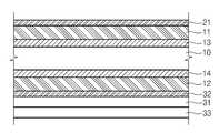
도 1은 본 발명의 일 실시예에 따른 열반사 헤드라이닝을 도시한 단면도이다.
도 2는 본 발명의 일 실시예에 따른 열반사 헤드라이닝의 열반사 분할시트들의 연결부를 도시한 도면이다.
도 3은 본 발명에 의한 열반사 헤드라이닝의 곡면 가공 시에 열반사 분할시트들의 인장방향 슬립상태를 도시한 도면이다.
도 4는 본 발명의 일 실시예에 따른 열반사 헤드라이닝의 제조방법을 도시한 공정도이다.
도 5는 제조설비 내에서 본 발명에 의한 열반사 헤드라이닝이 제조되는 과정을 도시한 도면이다.1 is a cross-sectional view illustrating a heat reflecting head lining according to an embodiment of the present invention.
FIG. 2 is a view showing a connection portion of heat reflective partition sheets of a heat reflective head lining according to an embodiment of the present invention.
3 is a view showing a tensile direction slip state of the heat reflective subdividing sheets in the curved surface processing of the heat reflecting head lining according to the present invention.
4 is a process diagram illustrating a method of manufacturing a thermally reflective head lining according to an embodiment of the present invention.
5 is a view showing a process of manufacturing a heat reflecting head lining according to the present invention in a manufacturing facility.
이하, 본 발명의 바람직한 실시예를 첨부된 도면을 참조하여 상세히 설명한다. 참고로, 본 발명을 설명하는 데 참조하는 도면에 도시된 구성요소의 크기, 선의 두께 등은 이해의 편의상 다소 과장되게 표현되어 있을 수 있다. 또, 본 발명의 설명에 사용되는 용어들은 본 발명에서의 기능을 고려하여 정의한 것이므로 사용자, 운용자 의도, 관례 등에 따라 달라질 수 있다. 따라서, 이 용어에 대한 정의는 본 명세서의 전반에 걸친 내용을 토대로 내리는 것이 마땅하겠다.Hereinafter, preferred embodiments of the present invention will be described in detail with reference to the accompanying drawings. For the sake of convenience, the size, line thickness, and the like of the components shown in the drawings referenced in the description of the present invention may be exaggerated somewhat. The terms used in the description of the present invention are defined in consideration of the functions of the present invention, and thus may be changed depending on the user, the intention of the operator, customs, and the like. Therefore, the definition of this term should be based on the contents of this specification as a whole.
도 1을 참조하면, 본 발명에 의한 열반사 헤드라이닝은, 기재(10)와, 기재(10)의 양면에 부착된 제1보강층(11) 및 제2보강층(12)과, 제1보강층(11)에 부착된 열반사층(21)과, 제2보강층(11)에 부착된 부직포층(31)을 포함할 수 있다1, a heat reflecting head lining according to the present invention comprises a
기재(10)는 반경질 폴리우레탄 발포폼 재질로 이루어질 수 있고, 기재(10)는 그 상면 및 하면이 평탄한 구조로 형성될 수 있다.The
기재(10)의 일면(즉, 기재(10)의 실외측 표면)에 접착층(13)이 형성될 수 있고, 이러한 접착층(13)에 의해 기재(10)의 실외측 표면에는 제1보강층(11)이 접착될 수 있다.An
기재(10)의 타면(즉, 기재(10)의 실내측 표면)에 접착층(14)이 형성될 수 있고, 이러한 접착층(14)을 통해 기재(10)의 실내측 표면에 제2보강층(12)이 접착될 수 있다.The
제1보강층(11)의 외면에 열반사층(21)이 부착될 수 있으며, 열반사층(21)은 알루미늄(Al), 스테인레스(SUS) 등과 같은 열반사성이 우수한 금속박판으로 구성될 수 있다.The
제2보강층(12)의 외면에는 부직포층(31)이 적층될 수 있으며, 특히 부직포층(31)과 제2보강층(12) 사이에는 필름(32)이 개재될 수 있다.The
한편, 제1보강층(11) 및 제2보강층(12)은 접착층(13, 14)의 접착제가 투과할 수 있는 무기섬유 재질로 이루어짐이 바람직하다. 이에, 제1보강층(11)과 제2보강층(12)이 기재(10)의 양면에 적층된 상태에서 상하방향으로 가열 및 가압되면 접착층(13, 14)의 접착제가 제1보강층(11) 및 제2보강층(12)을 투과할 수 있고, 이렇게 투과된 접착제에 의해 열반사층(21)은 제1보강층(11)의 외면에 견고하게 부착됨과 더불어 부직포층(31) 및 필름(32)이 제2보강층(12)의 외면에 견고하게 부착될 수 있다.On the other hand, it is preferable that the first reinforcing
일 실시예에 따르면, 필름(32)은 복수의 기공을 가진 통기성 필름으로 이루어지고, 기공의 직경은 0.1~2mm이며, 상기 기공들 사이의 간격은 1~40mm일 수 있다.According to one embodiment, the
이와 같이 통기성 필름(32)이 제2보강층(12)과 부직포층(12) 사이에 개재됨으로써 기재(10)의 실내측 표면에 도포된 접착층(14)의 접착제가 제2보강층(12) 및 통기성필름을 투과할 수 있고, 이렇게 투과된 접착제에 의해 부직포층(12)은 필름(32) 및 제2보강층(12)에 견고하게 부착될 수 있다.The air
다른 실시예에 따르면, 필름(32)은 핫멜트 필름으로 이루어질 수 있으며, 이에 가열 및 가압 시에 핫멜트 필름이 용융되면서 부직포층(12)은 제2보강층(12)에 보다 견고하게 부착될 수도 있다.According to another embodiment, the
이와 같이, 부직포층(12)은 제2보강층(12)을 투과한 접착제에 의해 부착될 수 있으므로 주름 내지 들뜸이 방지될 수 있다.As described above, since the
그리고, 부직포층(31)의 외면에는 표피층(33)이 부착될 수 있고, 이러한 표피층(33)이 부직포층(31)을 완전히 덮을 수 있으므로 헤드라이닝의 실내측 표면의 외관미가 더욱 미려하게 이루어질 수도 있다. 이러한 표피층(33)은 부직포로 이루어질 수 있다.Since the
도 2 및 도 3을 참조하면, 본 발명에 의한 열반사층(21)은 분할된 2 이상의 열반사 분할시트(21a, 21b)로 이루어질 수 있다. 이러한 열반사 분할시트(21a, 21b)들이 서로 연결되는 부분은 서로 중첩됨으로써 중첩부(23)를 형성할 수 있고, 이러한 중첩부(23)에는 접착제(25)를 개재할 수 있다.2 and 3, the
이를 통해, 헤드라이닝의 곡면 가공 시에 도 3과 같이 2 이상의 열반사 분할시트(21a, 21b)들은 중첩부(23)에 개재된 접착제(25)에 의해 인장방향으로 슬립이 용이하게 이루어져 종래기술과 같은 찢어짐 등이 확실하게 방지될 수 있는 장점이 있다.3, the two or more heat-
도 4 및 도 5을 참조하면, 본 발명에 의한 열반사 헤드라이닝의 제조방법은 기재(10)의 양면에 접착제를 도포하여 접착층(13, 14)을 형성하는 접착제 도포단계(S1)와, 기재(10)의 일면에 제1보강층(11) 및 열반사층(21)을 순차적으로 적층함과 더불어 기재(10)의 타면에 제2보강층(12) 및 부직포층(31)을 순차적으로 적층함으로써 적층체(19) 형성하는 적층단계(S2)와, 적층체(19)의 상하방향에서 열을 인가하면서 가압하는 가압단계(S3)를 포함할 수 있다.4 and 5, a method of manufacturing a thermally reflective head lining according to the present invention includes an adhesive applying step (S1) of forming an adhesive layer (13, 14) by applying an adhesive to both surfaces of a substrate (10) The second reinforcing
접착제 도포단계(S1)는, 도 5와 같이 기재(10)가 이송라인(40)을 통해 이송될 때 한 쌍의 분사노즐(41, 42)이 기재(10)의 상면 및 하면에 접착제를 도포함으로써 기재(10)의 양면에 접착층(13, 14)을 형성하는 공정이다.The adhesive application step S1 is a step in which a pair of
적층단계(S2)는, 도 5와 같이 적층기구(50)에 의해 기재(10)의 양면에 제1보강층(11) 및 열반사층(21), 제2보강층(12) 및 부직포층(31)을 적층하는 공정이다. 적층기구(50)는 제1보강층을 공급하는 제1보강층 공급부(51)와, 열반사층(21)을 공급하는 열반사층 공급부(53)와, 제2보강층(12)을 공급하는 제2보강층 공급부(52)와, 부직포층(31)을 공급하는 부직포층 공급부(54)를 가질 수 있다. 상술한 각 공급부(51, 52, 53, 54)를 통해 공급되는 소재들은 복수의 이송롤러 등을 통해 기재(10)의 양면에 안정적으로 안내될 수 있다.The lamination step S2 is a step of forming the first reinforcing
이러한 적층단계(S2)를 거치면서, 기재(10)의 일면에는 제1보강층(11) 및 열반사층(21)이 적층되고, 기재(10)의 타면에는 제2보강층(12) 및 부직포층(31)이 적층됨으로써 적층체(19)가 형성될 수 있다.The first reinforcing
한편, 적층단계(S2)에서, 제2보강층(12)과 부직포층(31) 사이에는 필름(32)을 개재할 수 있으며, 또한 부직포층(31)의 외면에는 표피층(33)을 적층할 수도 있다.On the other hand, in the laminating step S2, the
가압단계(S3)는, 상부가압금형(61) 및 하부가압금형(62)이 상하방향에서 적층체(19)의 상면 및 하면에 열을 인가하면서 가압함으로써 적층체(19)들의 각 요소들이 서로 견고하게 부착될 수 있다.The pressing step S3 presses the
가압단계(S3) 이후에는 가압된 적층체의 외관을 트리밍하는 트리밍단계(S4)를 더 포함할 수 있고, 이러한 트리밍을 통해 소정 형상의 열반사 헤드라이닝의 가공이 완료될 수 있다.After the pressing step S3, a trimming step S4 may be further performed to trim the appearance of the pressurized laminate. Through this trimming, the processing of the heat reflective headlining of a predetermined shape can be completed.
이상, 본 발명의 구체적인 실시예를 설명하였으나, 본 발명은 이 명세서에 개시된 실시예 및 첨부된 도면에 의하여 한정되지 않으며 본 발명의 기술적 사상을 벗어나지 않는 범위 이내에서 당업자에 의하여 다양하게 변형될 수 있다.While the present invention has been described in connection with what is presently considered to be practical exemplary embodiments, it is to be understood that the invention is not limited to the disclosed embodiments, but, on the contrary, is intended to cover various modifications and equivalent arrangements included within the spirit and scope of the appended claims. .
10: 기재11: 제1보강층
12: 제2보강층13, 14: 접착층
21: 열반사층31: 부직포층
32: 필름33: 표피층10: substrate 11: first reinforcing layer
12: second reinforcing
21: heat reflecting layer 31: nonwoven fabric layer
32: Film 33: Skin layer
Claims (12)
Translated fromKorean상기 기재의 실외측 표면에 접착층을 통해 부착된 제1보강층;
상기 제1보강층의 외면에 부착된 열반사층;
상기 기재의 실내측 표면에 접착층을 통해 부착된 제2보강층; 및
상기 제2보강층의 외면에 부착된 부직포층;을 포함하고,
상기 열반사층은 금속박판으로 이루어지며, 상기 제1 및 제2 보강층은 상기 접착층이 투과되는 무기섬유 재질로 이루어지는 것을 특징으로 하는 열반사 헤드라이닝.materials;
A first reinforcing layer attached to the outdoor side surface of the substrate through an adhesive layer;
A heat reflecting layer attached to an outer surface of the first reinforcing layer;
A second reinforcing layer attached to the inside surface of the base material through an adhesive layer; And
And a nonwoven fabric layer attached to an outer surface of the second reinforcing layer,
Wherein the heat reflecting layer is made of a thin metal plate, and the first and second reinforcing layers are made of an inorganic fiber material through which the adhesive layer is transmitted.
상기 기재는 반경질 폴리우레탄 발포폼 재질로 이루어지는 것을 특징으로 하는 열반사 헤드라이닝.The method according to claim 1,
Characterized in that the substrate is made of a semi-rigid polyurethane foam foam material.
상기 제2보강층과 상기 부직포층 사이에는 필름이 개재되는 것을 특징으로 하는 열반사 헤드라이닝.The method according to claim 1,
And a film is interposed between the second reinforcing layer and the nonwoven fabric layer.
상기 필름은 복수의 기공을 가진 통기성 필름으로 이루어지고, 상기 기공의 직경은 0.1~2mm이고, 상기 기공들 사이의 간격은 1~40mm인 것을 특징으로 하는 열반사 헤드라이닝.The method of claim 3,
Wherein the film is made of a breathable film having a plurality of pores, wherein the pores have a diameter of 0.1 to 2 mm and an interval between the pores is 1 to 40 mm.
상기 필름은 핫멜트 필름으로 이루어지는 것을 특징으로 하는 열반사 헤드라이닝.The method of claim 3,
Wherein the film is made of a hot-melt film.
상기 부직포층의 외면에는 표피층이 부착되는 것을 특징으로 하는 열반사 헤드라이닝.The method according to claim 1,
And a skin layer is adhered to the outer surface of the nonwoven fabric layer.
상기 표피층은 부직포로 이루어지는 것을 특징으로 하는 열반사 헤드라이닝.The method of claim 6,
Wherein the skin layer is made of a nonwoven fabric.
상기 열반사층은 분할된 2 이상의 열반사 분할시트로 이루어지고, 상기 열반사 분할시트들이 서로 연결되는 부분에는 중첩부가 형성되며, 상기 중첩부에는 접착제가 개재되는 것을 특징으로 하는 열반사 헤드라이닝.The method according to claim 1,
Wherein the heat reflecting layer is composed of two or more divided heat reflecting divided sheets, the overlapped portion is formed at a portion where the heat reflecting divided sheets are connected to each other, and the adhesive is interposed in the overlapped portion.
상기 기재의 일면에 제1보강층 및 열반사층을 순차적으로 적층함과 더불어, 상기 기재의 타면에 제2보강층 및 부직포층을 순차적으로 적층함으로써 적층체를 형성하는 적층단계; 및
상기 적층체에 대해 상하방향에서 열을 인가하면서 가압하는 가압단계;를 포함하는 것을 특징으로 하는 열반사 헤드라이닝의 제조방법.An adhesive applying step of applying an adhesive layer to both surfaces of the substrate;
A lamination step of sequentially laminating a first reinforcing layer and a heat reflecting layer on one surface of the base material and sequentially laminating a second reinforcing layer and a nonwoven fabric layer on the other surface of the base material to form a laminate; And
And a pressing step of applying pressure to the laminate while applying heat in a vertical direction.
상기 적층단계에서, 상기 제2보강층과 상기 부직포층 사이에는 필름층을 개재하는 단계를 더 포함하는 것을 특징으로 하는 열반사 헤드라이닝의 제조방법.The method of claim 9,
Further comprising a step of interposing a film layer between the second reinforcing layer and the nonwoven fabric layer in the laminating step.
상기 적층단계에서, 상기 부직포층의 외면에는 표피층을 적층하는 단계를 더 포함하는 것을 특징으로 하는 열반사 헤드라이닝의 제조방법.The method of claim 9,
Further comprising laminating a skin layer on an outer surface of the nonwoven fabric layer in the laminating step.
상기 가압단계 이후에는, 가압된 적층체의 외관을 트리밍하는 트리밍단계를 포함하는 것을 특징으로 하는 열반사 헤드라이닝의 제조방법.The method of claim 9,
And after the pressing step, a trimming step of trimming an outer appearance of the pressurized laminate.
Priority Applications (1)
| Application Number | Priority Date | Filing Date | Title |
|---|---|---|---|
| KR1020150169986AKR20170064339A (en) | 2015-12-01 | 2015-12-01 | Heat reflective headlining and method for manufacturing the same |
Applications Claiming Priority (1)
| Application Number | Priority Date | Filing Date | Title |
|---|---|---|---|
| KR1020150169986AKR20170064339A (en) | 2015-12-01 | 2015-12-01 | Heat reflective headlining and method for manufacturing the same |
Publications (1)
| Publication Number | Publication Date |
|---|---|
| KR20170064339Atrue KR20170064339A (en) | 2017-06-09 |
Family
ID=59220015
Family Applications (1)
| Application Number | Title | Priority Date | Filing Date |
|---|---|---|---|
| KR1020150169986ACeasedKR20170064339A (en) | 2015-12-01 | 2015-12-01 | Heat reflective headlining and method for manufacturing the same |
Country Status (1)
| Country | Link |
|---|---|
| KR (1) | KR20170064339A (en) |
Cited By (1)
| Publication number | Priority date | Publication date | Assignee | Title |
|---|---|---|---|---|
| KR20180011401A (en)* | 2016-07-21 | 2018-02-01 | (주)대한솔루션 | Material for head ling of vehicle |
- 2015
- 2015-12-01KRKR1020150169986Apatent/KR20170064339A/ennot_activeCeased
Cited By (1)
| Publication number | Priority date | Publication date | Assignee | Title |
|---|---|---|---|---|
| KR20180011401A (en)* | 2016-07-21 | 2018-02-01 | (주)대한솔루션 | Material for head ling of vehicle |
Similar Documents
| Publication | Publication Date | Title |
|---|---|---|
| FI107593B (en) | A method for making a composite sheet from a honeycomb structure and at least one cover layer | |
| US11964456B2 (en) | Fire-resistant, gas permeable decorative laminate | |
| JP2016514634A5 (en) | ||
| ES2536176T3 (en) | Roof trim and procedure for obtaining a roof trim for vehicles | |
| HUP0203061A2 (en) | Rooflining of a vehicle and a method for producing same | |
| US20160121837A1 (en) | Method of manufacturing a trim component with hidden tear pattern and trim component with hidden tear pattern | |
| JP6170567B2 (en) | Slide fastener stringer and manufacturing method thereof | |
| KR101598445B1 (en) | Ventilation seat cover for vehicle and manufacturing method thereof | |
| KR20170109802A (en) | Wall Decorating Members For Interior And Method For Manufacturing The Same | |
| US20230311455A1 (en) | Reflective Insulation | |
| KR20170064339A (en) | Heat reflective headlining and method for manufacturing the same | |
| CN101626888A (en) | Method of manufacturing a composite textile | |
| JP2002046545A (en) | Vehicular molded ceiling material and its manufacturing method | |
| CN104924720B (en) | Preparation method of textile wall covering with hot-melt adhesion property | |
| JP5762272B2 (en) | Vehicle ceiling material | |
| JP2008150005A (en) | In-cabin ceiling material of automobile | |
| JP5268685B2 (en) | Method for producing laminated molded product and molding die used for the method | |
| KR102270994B1 (en) | Wall Decorating Members For Interior And Method For Manufacturing The Same | |
| JP2005127420A (en) | Manufacturing method of thermal insulation laminated panel | |
| JP5626905B2 (en) | Vehicle ceiling material | |
| FR2299964A1 (en) | Composite rubber-bonded panels - of thermoplastic foam and corrugated card for lightweight, stiff heat resistant vehicle head linings etc. | |
| US20100203319A1 (en) | Method Of Making A Breathable Film Laminate And A Breathable Film Laminate Produced Therefrom | |
| JP7198709B2 (en) | METHOD FOR MANUFACTURING MULTILAYER STRUCTURE SOUND INSULATION MATERIAL FOR VEHICLE, AND THERMOPLASTIC RESIN FILM USED FOR MULTILAYER STRUCTURE SOUND INSULATION MATERIAL FOR VEHICLE | |
| JPH08238638A (en) | Method for producing fiber-reinforced thermoplastic resin molding | |
| KR20150081041A (en) | manufacturing apparatus of air cap for heat insulation and its method |
Legal Events
| Date | Code | Title | Description |
|---|---|---|---|
| A201 | Request for examination | ||
| PA0109 | Patent application | Patent event code:PA01091R01D Comment text:Patent Application Patent event date:20151201 | |
| PA0201 | Request for examination | ||
| E902 | Notification of reason for refusal | ||
| PE0902 | Notice of grounds for rejection | Comment text:Notification of reason for refusal Patent event date:20161221 Patent event code:PE09021S01D | |
| E601 | Decision to refuse application | ||
| PE0601 | Decision on rejection of patent | Patent event date:20170530 Comment text:Decision to Refuse Application Patent event code:PE06012S01D Patent event date:20161221 Comment text:Notification of reason for refusal Patent event code:PE06011S01I | |
| PG1501 | Laying open of application |