KR20170062199A - Touchless 3d position sensor - Google Patents
Touchless 3d position sensorDownload PDFInfo
- Publication number
- KR20170062199A KR20170062199AKR1020150167715AKR20150167715AKR20170062199AKR 20170062199 AKR20170062199 AKR 20170062199AKR 1020150167715 AKR1020150167715 AKR 1020150167715AKR 20150167715 AKR20150167715 AKR 20150167715AKR 20170062199 AKR20170062199 AKR 20170062199A
- Authority
- KR
- South Korea
- Prior art keywords
- light
- light receiving
- output terminal
- converter
- photodiode array
- Prior art date
- Legal status (The legal status is an assumption and is not a legal conclusion. Google has not performed a legal analysis and makes no representation as to the accuracy of the status listed.)
- Granted
Links
Images


Classifications
- G—PHYSICS
- G06—COMPUTING OR CALCULATING; COUNTING
- G06F—ELECTRIC DIGITAL DATA PROCESSING
- G06F3/00—Input arrangements for transferring data to be processed into a form capable of being handled by the computer; Output arrangements for transferring data from processing unit to output unit, e.g. interface arrangements
- G06F3/01—Input arrangements or combined input and output arrangements for interaction between user and computer
- G06F3/03—Arrangements for converting the position or the displacement of a member into a coded form
- G06F3/0304—Detection arrangements using opto-electronic means
Landscapes
- Engineering & Computer Science (AREA)
- General Engineering & Computer Science (AREA)
- Theoretical Computer Science (AREA)
- Human Computer Interaction (AREA)
- Physics & Mathematics (AREA)
- General Physics & Mathematics (AREA)
- Position Input By Displaying (AREA)
Abstract
Translated fromKoreanDescription
Translated fromKorean본 발명은 비접촉식 3D 위치 감지 센서에 관한 것으로서, 물체에 의해서 반사되는 광신호를 이용하여 물체의 3D 위치 또는 틸팅(tilting) 각도를 감지하는 장치에 관한 것이다.Field of the Invention [0002] The present invention relates to a non-contact 3D position sensing sensor, and more particularly, to an apparatus for sensing a 3D position or a tilting angle of an object using an optical signal reflected by an object.
TV나 컴퓨터 모니터 등과 같은 디스플레이 장치는 일반적으로는 컴퓨터나 모니터 등에 직접 연결된 버튼 입력 또는 마우스 입력에 의해 원하는 정보를 디스플레이 장치에 내장되거나 이에 연결된 연산장치를 통하여 입력 및 처리한다.A display device such as a TV or a computer monitor generally inputs and processes desired information through a button input or a mouse input directly connected to a computer or a monitor through a computing device built in or connected to the display device.
최근에는 이러한 전통적인 입력방식에서 탈피하여 여러 가지 형태의 주된 또는 보조적인 입력방식이 채택되고 있는데, 터치 스크린 방식은 유용하게 이용되는 새로운 입력방식 중 하나이다. 터치 스크린 방식은 디스플레이 장치의 스크린 측에 저항막 또는 초음파 등의 수단을 이용하여 입력자가 손가락 또는 기타의 입력 수단으로 스크린을 터치할 때 발생되는 화면의 저항이 변동하거나 또는 탄성 표면파가 발생하는 현상을 감지하여 터치된 부분의 화면상의 좌표를 검지하여 좌표에 정보를 입력하고 그에 따라 명령을 수행하는 방식이다.In recent years, various types of main or auxiliary input methods have been adopted to overcome this conventional input method. Touch screen method is one of new input methods that is useful. The touch screen method uses a resistance film or an ultrasonic wave on a screen side of a display device to change a resistance of a screen generated when a user touches the screen with a finger or other input means or to generate a surface acoustic wave Detecting the coordinate on the screen of the touched portion, inputting information in the coordinates, and executing the command accordingly.
이와 같은 터치 스크린 방식의 입력 방식을 사용할 경우 원하는 정보를 간편하게 입력할 수 있다는 장점이 있다.When such a touch screen type input method is used, there is an advantage that desired information can be easily input.
그러나 입력 장치를 이용하는 디스플레이 장치가 점차 대형화 되어가는 추세에 따라, 디스플레이 장치와 조작자 사이의 거리도 역시 멀어지게 되고, 그럼으로써 조작자가 간단히 손을 뻗어서 터치할 수 있던 종래의 조건에 비하여 조작자와 스크린 사이의 간격이 조작자의 팔길이 이상으로 멀어지게 되는 경우가 빈번하게 발생하며, 그에 따라 조작자가 이동하여 스크린의 표면을 터치하여야 한다는 불편함이 발생하게 되었다.However, as the display device using the input device is becoming larger and larger, the distance between the display device and the operator is also distant, and thus, compared with the conventional condition in which the operator can easily reach out and touch, The operator often moves away from the operator's arm length, and the operator must move to touch the surface of the screen.
또한, 터치 스크린 방식과 같은 접촉식 좌표 입력방식은 접촉에 의한 화면의 오염문제와 함께 화면에 반복적인 하중 부하를 가하게 되므로 디스플레이 장치 패널의 내구성을 해할 우려가 있다.In addition, the contact-type coordinate input method such as the touch screen method causes a problem of contamination of the screen due to contact, and repeatedly applies a load load to the screen, thereby deteriorating the durability of the display device panel.
이러한 문제점을 해결하기 위하여 비접촉식 좌표입력 시스템이 개발되게 되었다. 비접촉식 좌표입력 시스템은 상술한 접촉식 좌표입력 시스템과는 달리 스크린과 입력수단(손가락, 펜 등)이 물리적인 접촉을 하지 않기 때문에 다른 방식의 입력수단과 센서를 사용한다.To solve this problem, a non-contact type coordinate input system has been developed. Unlike the contact-type coordinate input system described above, the non-contact type coordinate input system uses a different type of input means and sensor because the screen and the input means (finger, pen, etc.) do not make physical contact.
즉, 비접촉식 좌표입력 시스템은 통상적으로는 빛을 이용하는 방식이 주로 사용되며, 빛을 스크린의 원하는 위치에 조사하고 빛이 조사된 위치의 좌표가 입력됨으로써 터치 스크린 방식과 동일한 기능을 수행하는 것이다. 이러한 용도에 사용되는 빛으로는 주로 레이저 광 등이 사용되지만 반드시 여기에 한정되지는 않으며, 빛이라 함은 적외선이나 자외선 등 모든 영역의 전자기파를 모두 함께 포함하는 개념이다.That is, the non-contact type coordinate input system generally uses a method using light, and performs the same function as the touch screen method by irradiating light at a desired position on the screen and inputting coordinates of a position where the light is irradiated. As the light used for such a purpose, mainly a laser beam is used but it is not necessarily limited to this, and the term " light " is a concept including all electromagnetic waves in all areas such as infrared rays and ultraviolet rays.
비접촉식 좌표입력 시스템의 일례로서 빛을 이용한 직접 포인팅 시스템에 관한 발명이 개시된 대한민국 공개특허공보 2001-0026856호를 들 수 있다. 이 발명은 리모콘을 일일이 조작하지 않더라도 원하는 메뉴를 직접 포인팅하여 쉽게 선택하기 위한 것으로서, 지시하고자 하는 방향을 향하여 레이저 광 등의 빛을 발사하고 선택하는 포인터와, 화면의 표면에 빛을 감지하는 패드를 부착하여 포인터에서 발사된 빛이 입사되는 화면상의 위치를 감지하는 감지부와, 감지부의 감지신호로부터 화면상의 위치를 계산하는 위치계산부와, 계산된 위치에 커서가 표시되도록 제어하며 포인터의 선택스위치 조작시 커서 위치의 메뉴에 해당하는 동작이 이루어지도록 제어하는 CPU, 및 CPU의 제어하에 커서를 생성하여 표시하는 커서 생성부로 구성되는 것을 특징으로 하는 시스템에 관한 것이다.An example of a non-contact type coordinate input system is Korean Patent Laid-Open Publication No. 2001-0026856, which discloses a direct pointing system using light. The present invention is directed to a method for directly selecting a desired menu by directly pointing a remote controller without operating the remote controller. The pointer is a pointer for emitting and selecting light such as a laser beam toward a direction to be instructed, A position calculator for calculating a position on the screen from a sensing signal of the sensing unit, a controller for controlling the cursor to be displayed at the calculated position, A CPU for controlling an operation corresponding to a menu at a cursor position during operation, and a cursor generating unit for generating and displaying a cursor under the control of the CPU.
직접 포인팅 시스템에 의할 경우에는 사용자가 리모콘을 일일이 조작하지 않고 스크린에 표시된 메뉴를 빛을 통해 직접 포인팅하여 쉽게 선택할 수 있는 효과를 얻을 수 있다.In case of using the direct pointing system, the user can easily select the menu displayed on the screen by directly pointing to the light without manipulating the remote controller.
이러한 비접촉식 좌표입력 시스템의 또 다른 일례로는 일본 특개평11-119910호에 기재된 입출력 장치를 들 수 있다.Another example of such a non-contact type coordinate input system is the input / output device described in Japanese Patent Laid-Open No. 11-119910.
입출력장치는 임의의 위치를 검출하고, 그것에 대응한 입력 등을 행하는 입출력 장치에 있어서, 표시화면을 비 접촉식으로 위치 입력을 행하도록 하는 것이다. 보다 구체적으로 설명하면, 입출력 장치는 표시화면의 임의의 위치를 조작함으로써, 그 위치를 검출하고, 그것에 대응한 입출력 처리를 행하는 입출력 장치로서, 표시화면 측으로부터 입력용 라이트펜에서 임의의 위치를 광조사하고, 그 조사위치를 표시장치와 일체적으로 설치한 다수의 매트릭스 배열된 광전환 소자에서 수광시켜서, 광전변환소자의 출력상태에 대응하여 위치검출을 행하는 것을 특징으로 한다.An input / output device detects an arbitrary position and performs an input corresponding to the input / output device. The input / output device causes the display screen to input a position in a non-contact manner. More specifically, the input / output device is an input / output device that detects a position of an arbitrary position of a display screen and performs input / output processing corresponding to the detected position, And the irradiation position is detected by a plurality of matrix-arranged light switching elements provided integrally with the display device to perform position detection corresponding to the output state of the photoelectric conversion element.
상술한 입출력 장치 역시 비접촉식으로 스크린에 정보를 입력할 수 있는 유용한 수단이다.The above-mentioned input / output device is also a useful means for inputting information on a screen in a non-contact manner.
그러나 대한민국 공개특허공보 제2001-0026856호에 기재된 발명 또는 일본 특개평 11-119910호에 기재된 발명은 각각의 좌표에 대응되는 격자점에 빛을 검출할 수 있는 센서를 배치하고 빛을 발광하는 포인터 등에서 발광된 빛이 각각의 센서에 도달하였을 때의 정보에 의해 좌표를 입력하는 방식을 채택하고 있다.However, the invention disclosed in Korean Patent Laid-Open Publication No. 2001-0026856 or the invention disclosed in Japanese Laid-Open Patent Publication No. 11-119910 is disadvantageous in that a sensor capable of detecting light is arranged at a lattice point corresponding to each coordinate and a pointer And the coordinates are input by the information when the emitted light reaches the respective sensors.
그러나 이러한 형태의 좌표입력방식은 디스플레이 장치가 대형화되거나 입력좌표를 보다 세밀하게 구분하여야 할 경우에 문제가 있을 수 있다. 즉, 좌표입력방식에서는 각각의 좌표에 대응하는 광센서 등의 센서를 배치하여야 하기 때문에 입력에 사용되는 좌표 숫자만큼 센서 숫자가 필요하고, 동일한 간격으로 센서를 배치할 경우 디스플레이 장치의 스크린 크기가 증가함에 따라 스크린 크기(가로 또는 세로 등)가 증가하는 정도의 제곱에 비례하여 센서의 필요량이 증가하게 되며 대형화된 입력장치에 센서를 배치하는 공정도 현실적으로 쉽지 않다.However, this type of coordinate input method may have a problem when the display device is enlarged or the input coordinates must be more finely divided. That is, in the coordinate input method, since a sensor such as an optical sensor corresponding to each coordinate must be arranged, the sensor number is required as many as the coordinate number used in the input, and when the sensor is arranged at the same interval, The required amount of the sensor increases in proportion to the square of the degree of increase of the screen size (such as the width or the height), and the process of disposing the sensor in the enlarged input device is not practical.
따라서, 디스플레이 장치가 대형화될 경우에는 센서사용량이 큰 부담이 될 수 있다. 이러한 현상은 좌표를 보다 세밀하게 구분하여야 할 경우에도 마찬가지로서, 좌표의 해상도가 증가할 경우 해상도가 증가한 만큼 센서를 추가로 배치하여야 하고 센서의 배치갯수는 좌표의 해상도의 제곱에 비례하여 증가하게 된다.Therefore, when the display device is enlarged, the sensor usage amount may become a heavy burden. In the same way, when the resolution of the coordinates increases, the number of sensors is increased as the resolution increases, and the number of the sensors is increased in proportion to the square of the resolution of the coordinates .
또한, 각각의 좌표에 센서를 배치하는 방식은 센서의 불투명성으로 인하여 센서가 위치하는 구역이 별도로 설정되고 나머지 영역을 화소영역으로 하여야 하기 때문에 화소영역의 면적을 충분히 확보하기 위해서는 센서가 매우 작아야 하거나 그렇지 않은 경우에는 화질이 열화될 수 있다는 문제가 발생할 수 있다In addition, in the method of arranging the sensor at each coordinate, since the area where the sensor is located is set separately due to the opacity of the sensor and the remaining area is used as the pixel area, the sensor must be very small in order to secure the area of the pixel area. There is a possibility that the image quality may deteriorate
본 발명의 목적은 사용자의 손의 위치와 틸팅 각도에 의해서 디스플레이 장치에서의 포인터를 자유자재로 이동시키고, 선택할 수 있는 비접촉식 3D 위치 감지센서를 제공하는데 있다.It is an object of the present invention to provide a
본 발명의 실시예에 따른 비접촉식 3D 위치 감지 센서는 광을 검출하여 물체의 위치 및 틸팅 각도를 감지하는 비접촉식 3D 위치 감지 센서로서, 광을 발산하는 발광부 및 상기 발광부에서 발산된 광이 물체에서 반사되는 반사광을 검출하는 수광부를 포함하고, 상기 수광부는 반사광에 의한 상기 수광부로 유입되는 광신호를 검출하는 수광센서, 상기 수광센서에 연결되어 상기 물체의 3D 위치 또는 틸팅각도를 판별하는 컨트롤러를 포함한다.A
여기서, 상기 수광센서는 사각형 각변의 길이방향으로 배치되는 제1 내지 제4 포토다이오드 어레이를 포함하고, 제1 포토다이오드 어레이 및 상기 제1 포토다이오드 어레이와 대향하는 방향에 위치하는 제2 포토다이오드 어레이의 출력단은 제1 차동증폭기에 연결되며, 제3 포토다이오드 어레이 및 상기 제3 포토다이오드 어레이와 대향하는 방향에 위치하는 제4 포토다이오드 어레이의 출력단은 제2 차동증폭기에 연결될 수 있다.Here, the light receiving sensor includes first to fourth photodiode arrays arranged in the longitudinal direction of each side of a quadrangle, and includes a first photodiode array and a second photodiode array positioned in a direction opposite to the first photodiode array The output terminal of the third photodiode array is connected to the first differential amplifier and the output terminal of the fourth photodiode array located in the direction facing the third photodiode array and the third photodiode array can be connected to the second differential amplifier.
여기서, 상기 제1 차동증폭기의 출력단은 제1컨버터에 연결되고, 제2 차동증폭기의 출력단은 제2컨버터에 연결되어 각각 디지털신호로 변환될 수 있다.Here, the output terminal of the first differential amplifier may be connected to the first converter, and the output terminal of the second differential amplifier may be connected to the second converter so as to be respectively converted into digital signals.
여기서, 상기 제1컨버터의 출력단과 제2컨버터의 출력단은 상기 컨트롤러와 연결될 수 있다.Here, the output terminal of the first converter and the output terminal of the second converter may be connected to the controller.
여기서, 상기 제1 내지 제4 포토다이오드 어레이의 출력단 각각에 병렬로 연결되는 서브출력단 각각은 서브 증폭기와 서브 컨버터를 경유하여 상기 컨트롤러와 연결될 수 있다.Each of the sub output terminals connected in parallel to the output terminals of the first through fourth photodiode arrays may be connected to the controller via a sub amplifier and a sub converter.
여기서, 상기 컨트롤러는 상기 제1컨버터의 출력단에서 입력되는 신호를 이용하여 X방향으로 위치 또는 틸팅 각도를 판정하고, 상기 제2컨버터의 출력단에서 입력되는 신호를 이용하여 Y방향으로 위치 또는 틸팅 각도를 판정하고, 상기 서브 컨버터들 각각의 출력단에서 입력되는 신호를 이용하여 상기 물체의 Z방향 위치를 판정할 수 있다.Here, the controller determines a position or tilting angle in the X direction using a signal input from the output terminal of the first converter, and determines a position or a tilting angle in the Y direction using a signal input from the output terminal of the second converter And the position of the object in the Z direction can be determined using the signal input at the output terminal of each of the sub-converters.
본 발명의 실시예에 따른 비접촉식 3D 위치 감지 센서는 틸팅된 각도에 따라서 포인터의 이동속도를 조절할 수 있다.The
또한, 사용자의 동작을 정확하게 인식할 수 있다.In addition, the operation of the user can be accurately recognized.
또한, 칩 형태로 구현되어 작은 크기로 제작이 가능하다.Also, it can be realized in chip form and can be manufactured in small size.
도 1은 본 발명의 실시예에 따른 비접촉식 3D 위치감지센서와 인식을 위한 물체(object)의 좌표정의 개략도이다.
도 2는 본 발명의 실시예에 따른 수광부의 평면도와 절단면도이다.
도 3은 본 발명의 실시예에 따른 수광부의 회로구성도이다.
도 4는 본 발명의 실시예에 따른 컨트롤러에서의 매핑을 통한 물체의 위치나 틸팅각도를 판정하는 개념도이다.
도 5는 검출된 광에 따른 전압값의 변화를 나타낸 그래프이다.BRIEF DESCRIPTION OF THE DRAWINGS FIG. 1 is a schematic diagram of coordinate definition of a non-contact 3D position sensing sensor and an object for recognition according to an embodiment of the present invention; FIG.
2 is a plan view and a cross-sectional view of a light receiving unit according to an embodiment of the present invention.
3 is a circuit diagram of a light-receiving unit according to an embodiment of the present invention.
4 is a conceptual diagram for determining the position or tilting angle of an object through mapping in a controller according to an embodiment of the present invention.
5 is a graph showing a change in the voltage value according to the detected light.
본 명세서에 개시되어 있는 본 발명의 개념에 따른 실시 예들에 대해서 특정한 구조적 또는 기능적 설명은 단지 본 발명의 개념에 따른 실시 예들을 설명하기 위한 목적으로 예시된 것으로서, 본 발명의 개념에 따른 실시 예들은 다양한 형태들로 실시될 수 있으며 본 명세서에 설명된 실시 예들에 한정되지 않는다.It is to be understood that the specific structural or functional description of embodiments of the present invention disclosed herein is for illustrative purposes only and is not intended to limit the scope of the inventive concept But may be embodied in many different forms and is not limited to the embodiments set forth herein.
본 발명의 개념에 따른 실시 예들은 다양한 변경들을 가할 수 있고 여러 가지 형태들을 가질 수 있으므로 실시 예들을 도면에 예시하고 본 명세서에서 상세하게 설명하고자 한다. 그러나 이는 본 발명의 개념에 따른 실시 예들을 특정한 개시 형태들에 대해 한정하려는 것이 아니며, 본 발명의 사상 및 기술 범위에 포함되는 모든 변경, 균등물, 또는 대체물을 포함한다.The embodiments according to the concept of the present invention can make various changes and can take various forms, so that the embodiments are illustrated in the drawings and described in detail herein. It is not intended to be exhaustive or to limit the invention to the particular forms disclosed, but on the contrary, is intended to cover all modifications, equivalents, or alternatives falling within the spirit and scope of the invention.
제1 또는 제2 등의 용어는 다양한 구성 요소들을 설명하는데 사용될 수 있지만, 상기 구성 요소들은 상기 용어들에 의해 한정되어서는 안 된다. 상기 용어들은 하나의 구성 요소를 다른 구성 요소로부터 구별하는 목적으로만, 예컨대 본 발명의 개념에 따른 권리 범위로부터 벗어나지 않은 채, 제1 구성 요소는 제2 구성 요소로 명명될 수 있고 유사하게 제2 구성 요소는 제1 구성 요소로도 명명될 수 있다.The terms first, second, etc. may be used to describe various elements, but the elements should not be limited by the terms. The terms may be named for the purpose of distinguishing one element from another, for example, without departing from the scope of the right according to the concept of the present invention, the first element may be referred to as a second element, The component may also be referred to as a first component.
어떤 구성 요소가 다른 구성 요소에 "연결되어" 있다거나 "접속되어" 있다고 언급된 때에는, 그 다른 구성 요소에 직접적으로 연결되어 있거나 또는 접속되어 있을 수도 있지만, 중간에 다른 구성 요소가 존재할 수도 있다고 이해되어야 할 것이다. 반면에, 어떤 구성 요소가 다른 구성 요소에 "직접 연결되어" 있다거나 "직접 접속되어" 있다고 언급된 때에는 중간에 다른 구성 요소가 존재하지 않는 것으로 이해되어야 할 것이다. 구성 요소들 간의 관계를 설명하는 다른 표현들, 즉 "~사이에"와 "바로 ~사이에" 또는 "~에 이웃하는"과 "~에 직접 이웃하는" 등도 마찬가지로 해석되어야 한다.It is to be understood that when an element is referred to as being "connected" or "connected" to another element, it may be directly connected or connected to the other element, . On the other hand, when an element is referred to as being "directly connected" or "directly connected" to another element, it should be understood that there are no other elements in between. Other expressions that describe the relationship between components, such as "between" and "between" or "neighboring to" and "directly adjacent to" should be interpreted as well.
본 명세서에서 사용한 용어는 단지 특정한 실시 예를 설명하기 위해 사용된 것으로서, 본 발명을 한정하려는 의도가 아니다. 단수의 표현은 문맥상 명백하게 다르게 뜻하지 않는 한, 복수의 표현을 포함한다. 본 명세서에서, "포함하다" 또는 "가지다" 등의 용어는 본 명세서에 기재된 특징, 숫자, 단계, 동작, 구성 요소, 부분품 또는 이들을 조합한 것이 존재함을 지정하려는 것이지, 하나 또는 그 이상의 다른 특징들이나 숫자, 단계, 동작, 구성 요소, 부분품 또는 이들을 조합한 것들의 존재 또는 부가 가능성을 미리 배제하지 않는 것으로 이해되어야 한다.The terminology used herein is for the purpose of describing particular embodiments only and is not intended to be limiting of the invention. The singular expressions include plural expressions unless the context clearly dictates otherwise. In this specification, the terms "comprises" or "having" and the like are used to specify that there are features, numbers, steps, operations, elements, parts or combinations thereof described herein, But do not preclude the presence or addition of one or more other features, integers, steps, operations, components, parts, or combinations thereof.
다르게 정의되지 않는 한, 기술적이거나 과학적인 용어를 포함해서 여기서 사용되는 모든 용어들은 본 발명이 속하는 기술 분야에서 통상의 지식을 가진 자에 의해 일반적으로 이해되는 것과 동일한 의미를 가진다. 일반적으로 사용되는 사전에 정의되어 있는 것과 같은 용어들은 관련 기술의 문맥상 가지는 의미와 일치하는 의미를 갖는 것으로 해석되어야 하며, 본 명세서에서 명백하게 정의하지 않는 한, 이상적이거나 과도하게 형식적인 의미로 해석되지 않는다.Unless defined otherwise, all terms used herein, including technical or scientific terms, have the same meaning as commonly understood by one of ordinary skill in the art to which this invention belongs. Terms such as those defined in commonly used dictionaries are to be interpreted as having a meaning consistent with the meaning of the context in the relevant art and, unless explicitly defined herein, are to be interpreted as ideal or overly formal Do not.
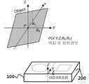
도 1은 본 발명의 실시예에 따른 비접촉식 3D 위치감지센서와 인식을 위한 물체(object)의 좌표정의 개략도이다.BRIEF DESCRIPTION OF THE DRAWINGS FIG. 1 is a schematic diagram of coordinate definition of a non-contact 3D position sensing sensor and an object for recognition according to an embodiment of the present invention; FIG.
도 1에 도시된 바와 같이 본 발명의 실시예에 따른 비접촉식 3D 위치 감지 센서는 장치의 상부에 놓이는 물체(손)에 의해서 반사되는 광을 측정하여 물체의 3D위치 및 틸팅 각도를 측정하기 위한 장치이다.As shown in FIG. 1, the
도 1에 도시된 3차원 직교좌표계에서 물체가 놓여 있는 평면과 수평인 X-Y평면이 X축과 이루는 각도 θx와 Y축과 이루는 각도 θy가 본 발명의 실시예에서 사용되는 틸팅각도(정보)이다.The angle θx formed between the plane on which the object is placed and the XY plane horizontal to the X axis and the angle θy formed with the Y axis in the three-dimensional Cartesian coordinate system shown in FIG. 1 is the tilting angle (information) used in the embodiment of the present invention, to be.
본 발명의 실시예에 따른 비접촉식 3D 위치 감지 센서는 광을 검출하여 물체의 위치 및 틸팅 각도를 감지하는 비접촉식 3D 위치 감지 센서로서, 광을 발산하는 발광부(100) 및 상기 발광부(100)에서 발산된 광이 물체에서 반사되는 반사광을 검출하는 수광부(200)를 포함하고, 상기 수광부(200)는 반사광에 의한 상기 수광부(200)로 유입되는 광신호를 검출하는 수광센서, 상기 수광센서에 연결되어 상기 물체의 3D 위치 및 틸팅 각도를 판별하는 컨트롤러를 포함한다.A
발광부(100)는 광을 발산한다. 자세하게는 비접촉식 3D 위치감지센서의 상부에 놓여 있는 물체를 향하여 발산되도록 하는 것이 바람직하다. 발광부(100)는 적외선 LED일 수 있으나 반드시 이에 제한되는 것은 아니다.The
발광부(100)에서 발산되는 광은 별도의 전원에 의해서 저전력으로 구동이 가능하고, 크기에 제한은 없으나 수 mm 내지 수십 mm이내의 작은 크기로 제작할 수 있다.The light emitted from the
수광부(200)는 발광부(100)에서 발산된 광이 물체에서 반사되는 반사광을 검출한다.The
도 2는 본 발명의 실시예에 따른 수광부의 평면도와 절단면도이다.2 is a plan view and a cross-sectional view of a light receiving unit according to an embodiment of the present invention.
도 3은 본 발명의 실시예에 따른 수광부의 회로구성도이다.3 is a circuit diagram of a light-receiving unit according to an embodiment of the present invention.
도 2, 도 3에 도시된 바와 같이 본 발명의 실시예에 따른 수광부(200)는 상부가 일부 개방된 직육면체 형상의 본체(210) 내부에 사각형 기판(280)이 설치되며, 기판(280)의 가장자리에 광을 검출하는 수광센서인 제1 내지 제4 포토다이오드 어레이(221, 222, 223, 224)를 포함한다.2 and 3, the
본체(210) 및 기판(280)의 형상은 앞서 언급한 형상에 국한되는 것은 아니며, 나아가 수광센서(220)의 형상은 다양하게 구현될 수 있고, 수광센서(220)는 본 발명을 구현하기 위한 기판(280)상의 변형가능한 위치에 설치될 수 있다. 예를 들어 수광센서(220)는 둘 이상의 포토다이오드, 포토트랜지스터 등 광신호를 검출할 수 있는 소자를 포함할 수 있으며, 기판의 가장자리에서 소정거리 이격된 위치에 설치될 수도 있다.The shapes of the
도 2(a)에 도시되어 있는 본 발명의 실시예에 따른 수광센서(220)는 사각형 각변의 길이방향으로 배치되는 제1 내지 제4 포토다이오드 어레이(221, 222, 223, 224)를 포함한다. 본 발명의 실시예에 따른 수광부(200)가 도 2(b)에 도시된 본체(210)의 형상을 갖는 경우에 하나의 포토다이오드 어레이에서 검출할 수 있는 영역이 제한된다.(FOVXL, FOVXR)The
또한, 도 3에서 FOV(Field Of View)가 중복되는 애매한 영역에 물체가 놓이는 경우 어느 방향에 물체가 놓여 있는지를 판정하기 곤란하다. 그러나 인식을 위한 물체의 크기에 비해서 중복되는 영역이 크지 않을 경우 양단 포토다이오드 어레이에 입사하는 광량의 변화로 인해서 물체의 위치 또는 틸팅된 정보를 판정할 수 있다. 본 발명의 실시예에 따른 비접촉식 3D 위치 감지장치는 반드시 그렇지는 않으나, 주로 애매한 영역에 물체(손)가 놓이고, 이때, 도 2에 도시된 바와 같이 물체의 틸팅정도를 판정하거나 물체가 놓인 위치를 검출할 수 있다. 또한, 앞선 도 1에 도시된 것과 같이 X, Y 어느 방향으로 물체가 진행하는지, 위치해 있는지와 물체가 수광센서로부터 어느 정도 높이에 위치해 있는지를 판정한다.Also, in FIG. 3, it is difficult to determine in which direction an object is placed when an object is placed in a blurred area where FOV (Field Of View) is overlapped. However, when the area overlapping with the size of the object for recognition is not large, the position of the object or the tilted information can be determined due to the change in the amount of light incident on the both-end photodiode array. The
도 3에 도시된 바와 같이 수광부(200)는 광이 입사하는 경우 전기신호를 생성하는 수광센서(220)를 포함하고, 본 발명의 실시예에 따른 수광센서(220)는 제1 내지 제4 포토다이오드 어레이(221, 222, 223, 224)를 포함하고, 제1 포토다이오드어레이(221)와 제2 포토다이오드 어레이(222)의 출력단은 제1차동증폭기(231)에 연결되며, 제3 포토다이오드 어레이(223)와 제4 포토다이오드 어레이(224)의 출력단은 제2차동증폭기(232)에 연결된다.3, the
또한, 도 3과 같이 제1차동증폭기(231)의 출력단은 제1컨버터(241)에 연결되고, 제2차동증폭기(232)의 출력단은 제2컨버터(242)에 연결되어 각각 디지털신호로 변환되고, 제1컨버터(241)의 출력단과 제2컨버터(242)의 출력단은 컨트롤러(250)와 연결된다.3, the output terminal of the first
나아가, 제1 내지 제4 포토다이오드 어레이(221, 222, 223, 224)의 출력단 각각에서 병렬로 연결되어 출력되는 또 다른 전압신호는 모두 더해지고 서브 증폭기(233)와 서브 컨버터(243)를 경유하여 컨트롤러(250)와 연결된다. 제1차동증폭기(231)와 제2차동증폭기(232)는 풀리 차동증폭기(Fully Differential Amplifier)일 수 있다. 풀리 차동증폭기는 두 개의 입력단과 두 개의 출력단으로 구성되는 차동증폭기로서, 두 입력단에 들어오는 신호의 차이값을 증폭시키는 증폭기이다.Further, all the other voltage signals connected in parallel at the output terminals of the first to
컨트롤러(250)는 제1컨버터(231)의 출력단에서 입력되는 신호를 이용하여 물체의 X방향으로 위치 또는 틸팅 각도를 판정하고, 제2컨버터(232)의 출력단에서 입력되는 신호를 이용하여 물체의 Y방향으로 위치 또는 틸팅 각도를 판정하고 서브 컨버터(243)의 출력단에서 입력되는 신호를 이용하여 물체의 Z방향 위치를 판정한다.The
도 4는 본 발명의 실시예에 따른 컨트롤러에서의 매핑을 통한 물체의 위치나 틸팅각도를 판정하는 개념도이다.4 is a conceptual diagram for determining the position or tilting angle of an object through mapping in a controller according to an embodiment of the present invention.
도 4에 도시된 바와 같이 본 발명의 실시예에 따른 비접촉식 3D 위치 감지 센서가 포함하는 컨트롤러(250)는 물체의 각 축에 대한 위치변화 X, Y, Z와 틸팅 각도의 변화 θx, θy에 대한 신호를 수광센서(220)를 통해서 입력받으면, 3D 매핑 또는 2D 매핑을 통해서 포인팅 위치를 변화시킬 수 있다.The
기존의 제스처 센서는 제스처 센서 위의 물체의 위치나 틸팅 각도에 따라서 상기 대응하는 제스처를 출력하는 기능을 수행한다. 하지만, 본 발명의 실시예에 따른 비접촉식 3D 위치 감지 센서는 물체의 3D 위치(X, Y, Z)와 X 또는 Y 방향 틸딩 각도(θx, θy)에 따라서 컨트롤러(3D mapper)(250)를 이용하여 도 4(a)와 같이 3D 위치 감지 정보(X', Y', Z') 또는 도 4(b)와 같이 틸팅 각도와 높이 (θx', θy', Z') 정보를 출력할 수 있으며, 사용자의 의도에 따라 2D(도 4(c)) 또는 1D 위치 정보 및 틸팅 각도(도 4(d))만을 출력할 수도 있다.The conventional gesture sensor performs the function of outputting the corresponding gesture according to the position of the object on the gesture sensor or the tilting angle. However, non-contact 3D position sensor according to an embodiment of the present invention includes a controller (3D mapper) according to the 3D position (X, Y, Z) with X or Y direction tilding angle (θx, θy) of the object (250) And the tilting angle and the height (?X ',?Y ', Z ') information as shown in FIG. 4A as 3D position detection information (X', Y ', Z' And output 2D (Fig. 4 (c)) or 1D position information and tilting angle (Fig. 4 (d)) according to the user's intention.
아래 수학식 1은 컨트롤러에 의한 3D 매핑의 예를 나타낸 수식이다.Equation (1) below is an example of 3D mapping by the controller.
[수학식 1][Equation 1]

수학식 1은 3D 매핑의 세가지 예를 도식화 한 것으로서, (a)는 전기적 신호 (Vx, Vy, Vz)가 3D 위치정보로 선형적으로 매핑되는 경우이고, (b)는 전기적 신호가 3D 위치정보로 2차 함수에 비례하게 매핑되는 경우이며, (c)는 전기적 신호가 3D 위치정보로 지수함수(exponential)에 비례하게 매핑되는 경우이다. 본 발명은 위의 세가지 매핑함수에만 국한되는 것은 아니다. 또한, 본 발명은 반드시 매핑을 통한 포인팅 위치 내지는 틸팅정보 출력 뿐만 아니라, 다양한 방법을 사용해서 물체의 움직임에 따른 포인팅 위치 내지는 틸팅정보를 출력할 수 있다.(A) shows a case where the electrical signals (Vx , Vy , Vz ) are linearly mapped to 3D position information, (b) shows an example in which an
앞선 도 1 내지 도 3를 통해서 본 발명의 실시예에 따른 비접촉식 3D 위치 감지 센서의 동작에 대해서 상세히 설명하면, 수광센서(220)의 제1 포토다이오드 어레이(221)를 왼쪽 포토다이오드(PDL) 어레이라 하고, 제2 포토다이오드 어레이(222)를 오른쪽 포토다이오드(PDR) 어레이라 하고, 제3 포토다이오드 어레이(223)를 위쪽 포토다이오드(PDT) 어레이라 하고, 제4 포토다이오드 어레이(224)를 아래 포토다이오드(PDB) 어레이라 한다.Described in detail the operation of the non-contact 3D position sensor according to an embodiment of the present invention, the foregoing also by from 1 to 3, the left side of the
도 1을 고려하여 물체를 y축방향(up, down방향)으로 기울이는 경우, 제3 포토다이오드 어레이(223)인 PDT와 제4 포토다이오드 어레이(224)인 PDB에서 광을 검출한다. 도 3에서 제3 포토다이오드 어레이(223)와 제4 포토다이오드 어레이(224)가 연결되어 있는 제2차동증폭기(232)에서는 제3 포토다이오드 어레이(223)와 제4 포토다이오드 어레이(224)에 입력된 신호의 차이를 컨트롤러(250)에 전달하고, 컨트롤러(250)는 틸팅된 방향을 결정하고, 신호의 차이값을 이용하여 틸팅된 각도를 판정한다.When the object is tilted in the y-axis direction (up or down direction) in consideration of FIG. 1, light is detected in PDT , which is the
또한, 도 1을 고려하여 물체를 x축방향(left, right방향)으로 기울이는 경우, 제1 포토다이오드 어레이(221)인 PDL과 제2 포토다이오드 어레이(222)인 PDR에서 광을 검출한다. 앞서와 마찬가지로 제1차동증폭기(231)에서는 제1 포토다이오드 어레이(221)와 제2 포토다이오드 어레이(222)에 입력된 신호의 차이를 컨트롤러(250)에 전달하고, 컨트롤러(250)는 틸팅된 방향을 결정하는데, 이 경우에는 틸팅된 방향이 왼쪽방향인지, 오른쪽 방향인지를 결정하고, 신호의 차이값을 이용하여 틸팅된 각도를 판정한다.Further, the detecting light in,
나아가, 물체가 선형적으로 이동하는 경우인 +X방향으로 치우쳐 위치하는 경우에는 제1 포토다이오드 어레이(221)인 PDL과 제2 포토다이오드 어레이(222)인 PDR에서 신호가 검출되고, 검출된 전압값의 차이가 양의 값을 갖고 미리 정해진 임계값 이상으로 크다고 하면 컨트롤러(250)는 물체가 오른편에 위치해 있다고 판정한다. +Y방향 또는 -Y방향으로 위치해 있는 경우에도 마찬가지이다.Furthermore, the object is positioned shifted to the + X direction when moving linearly, the signal is detected in the PDR
도 5는 검출된 광에 따른 전압값의 변화를 나타낸 그래프이다.5 is a graph showing a change in the voltage value according to the detected light.
도 5는 실제 x축 방향으로 기울인 경우 제1차동증폭기(231)의 출력단에 오실로스코프의 각 단자를 연결하여 나온 전압레벨값의 변화를 도시한 그래프로서, 발광부의 LED가 일정한 주기로 On/Off를 반복할때, 물체의 왼쪽(Left)이 상승한 상태로 기울어진 경우 제1 포토다이오드 어레이(221)인 PDL은 LED가 On된 상태와 유사위상의 전압값이 검출된다. 반대로 제2 포토다이오드 어레이(222)인 PDR은 LED가 On된 상태와 반대위상의 전압값이 검출된다.5 is a graph showing changes in the voltage level value obtained by connecting the respective terminals of the oscilloscope to the output terminal of the first
도 5에서 물체가 오른쪽(right)이 상승한 상태로 기울어진 경우, 제1 포토다이오드 어레이(221)와 제2 포토다이오드 어레이(222)의 전압값이 앞서 설명한 것과는 반대임을 확인할 수 있다.5, it can be seen that the voltage values of the
도 5와 같이 x축 방향으로 기울어진 경우에는 PDL, PDR의 신호가 제1 차동증폭기(231)를 통과하고 제1컨버터(ADC)(241)를 지나 컨트롤러(250)의 단자(X)에 입력된다. 다만, 이 경우에도 PDT, PDB에도 광신호가 입력되어 소정의 전압값이 검출되나 x축 방향으로 기울어진 경우에 PDT와 PDB간의 차이는 거의 없는 것으로 판정된다. 또한, y축 방향으로 기울어진 경우에는 PDT, PDB의 신호가 제2 차동증폭기(232)를 통과하고, 제2컨버터(ADC)(242)를 지나 컨트롤러(250)의 단자(Y)에 입력된다.In PDL, the terminal (X) of the signal of the PDR pass through the first
컨트롤러(250)는 입력되는 신호의 극성과 크기를 이용하여 x축으로 물체의 기울어진 방향과 기울어진 정도를 판정하고, y축으로 물체의 기울어진 방향과 기울어진 정도를 판정한다.The
서브 증폭기(233)는 제1 내지 제4 포토다이오드 어레이(221, 222, 223, 224)에 입력되는 신호가 모두 더해진 이후에 이를 증폭시키고, 서브 컨버터(243)는 이를 디지털신호로 변환하며 컨트롤러(250)는 입력되는 신호를 이용하여 물체의 위치를 판정한다. 4개의 단자에 입력되는 신호의 세기 합을 이용하여 물체의 위치, 즉 물체가 수광부(200)로부터 위치한 높이를 판정한다. 높이를 판정하는 방법은 다양하게 구현될 수 있고, 일 예로 미리 신호세기합에 따른 높이의 상관데이터를 저장해 놓고, 상관데이터에 따라서 신호세기합과 매칭되는 높이를 실제 물체가 위치해 있는 높이로 판정하는 방법을 사용할 수 있다.The sub-amplifier 233 amplifies the signals input to the first through
이상 살펴본 수광부는 단일칩으로 구현될 수 있으며, 또한 도 1과 같이 발광부(100)와 수광부(200)를 하나의 패키지로 제작할 수 있다.The light receiving unit as described above can be implemented as a single chip, and the
100 발광부 200 수광부
210 본체 220 수광센서
221 제1 포토다이오드 어레이 222 제2 포토다이오드 어레이
223 제3 포토다이오드 어레이 224 제4 포토다이오드 어레이
231 제1차동증폭기 232 제2차동증폭기
233 서브증폭기 241 제1컨버터
242 제2컨버터 243 서브컨버터100
210
221
223
231 First
233
242
Claims (6)
Translated fromKorean광을 발산하는 발광부; 및
상기 발광부에서 발산된 광이 물체에서 반사되는 반사광을 검출하는 수광부를 포함하고,
상기 수광부는 반사광에 의한 상기 수광부로 유입되는 광신호를 검출하는 수광센서;
상기 수광센서에 연결되어 상기 물체의 3D 위치 또는 틸팅각도를 판별하는 컨트롤러를 포함하는 것을 특징으로 하는 비접촉식 3D 위치 감지 센서.A non-contact 3D position sensing sensor for sensing light and detecting an object's position and tilting angle,
A light emitting portion for emitting light; And
And a light receiving unit for detecting reflected light reflected from the object by the light emitted from the light emitting unit,
The light receiving unit includes a light receiving sensor for detecting an optical signal flowing into the light receiving unit by reflected light;
And a controller connected to the light receiving sensor to determine a 3D position or a tilting angle of the object.
상기 수광센서는 사각형 각변의 길이방향으로 배치되는 제1 내지 제4 포토다이오드 어레이를 포함하고, 제1 포토다이오드 어레이 및 상기 제1 포토다이오드 어레이와 대향하는 방향에 위치하는 제2 포토다이오드 어레이의 출력단은 제1차동증폭기에 연결되며, 제3 포토다이오드 어레이 및 상기 제3 포토다이오드 어레이와 대향하는 방향에 위치하는 제4 포토다이오드 어레이의 출력단은 제2차동증폭기에 연결되는 것을 특징으로 하는 비접촉식 3D 위치 감지 센서.The method according to claim 1,
Wherein the light receiving sensor includes first through fourth photodiode arrays arranged in the longitudinal direction of each side of a quadrangle, the first photodiode array and the output end of a second photodiode array positioned in a direction opposite to the first photodiode array, Is connected to the first differential amplifier and the output terminal of the fourth photodiode array, which is located in the direction opposite to the third photodiode array, is connected to the second differential amplifier. Detection sensor.
상기 제1차동증폭기의 출력단은 제1컨버터에 연결되고, 제2차동증폭기의 출력단은 제2컨버터에 연결되어 각각 디지털신호로 변환되는 것을 특징으로 하는 비접촉식 3D 위치 감지 센서.3. The method of claim 2,
Wherein the output terminal of the first differential amplifier is connected to the first converter and the output terminal of the second differential amplifier is connected to the second converter and converted into a digital signal.
상기 제1컨버터의 출력단과 제2컨버터의 출력단은 상기 컨트롤러와 연결되는 것을 특징으로 하는 비접촉식 3D 위치 감지 센서.The method of claim 3,
Wherein the output terminal of the first converter and the output terminal of the second converter are connected to the controller.
상기 제1 내지 제4 포토다이오드 어레이의 출력단 각각에 병렬로 연결되는 서브출력단 각각은 서브 증폭기와 서브 컨버터를 경유하여 상기 컨트롤러와 연결되는 것을 특징으로 하는 비접촉식 3D 위치 감지 센서.5. The method of claim 4,
And each sub output terminal connected in parallel to each of the output terminals of the first through fourth photodiode arrays is connected to the controller via the sub amplifier and the sub converter.
상기 컨트롤러는 상기 제1컨버터의 출력단에서 입력되는 신호를 이용하여 X방향으로 위치 또는 틸팅 각도를 판정하고, 상기 제2컨버터의 출력단에서 입력되는 신호를 이용하여 Y방향으로 위치 또는 틸팅 각도를 판정하고, 상기 서브 컨버터들 각각의 출력단에서 입력되는 신호를 이용하여 상기 물체의 Z방향 위치를 판정하는 것을 특징으로 하는 비접촉식 3D 위치 감지 센서.6. The method of claim 5,
The controller determines a position or tilting angle in the X direction by using a signal input from the output terminal of the first converter and determines a position or tilting angle in the Y direction using a signal input at the output terminal of the second converter And determines the position of the object in the Z direction by using a signal input from an output terminal of each of the sub-converters.
Priority Applications (1)
| Application Number | Priority Date | Filing Date | Title |
|---|---|---|---|
| KR1020150167715AKR101746014B1 (en) | 2015-11-27 | 2015-11-27 | Touchless 3d position sensor |
Applications Claiming Priority (1)
| Application Number | Priority Date | Filing Date | Title |
|---|---|---|---|
| KR1020150167715AKR101746014B1 (en) | 2015-11-27 | 2015-11-27 | Touchless 3d position sensor |
Publications (2)
| Publication Number | Publication Date |
|---|---|
| KR20170062199Atrue KR20170062199A (en) | 2017-06-07 |
| KR101746014B1 KR101746014B1 (en) | 2017-06-12 |
Family
ID=59219556
Family Applications (1)
| Application Number | Title | Priority Date | Filing Date |
|---|---|---|---|
| KR1020150167715AActiveKR101746014B1 (en) | 2015-11-27 | 2015-11-27 | Touchless 3d position sensor |
Country Status (1)
| Country | Link |
|---|---|
| KR (1) | KR101746014B1 (en) |
Families Citing this family (1)
| Publication number | Priority date | Publication date | Assignee | Title |
|---|---|---|---|---|
| KR102609695B1 (en)* | 2022-12-02 | 2023-12-05 | (주)대영엔씨디 | Dry road and building floor cutting device equipped with a dust inhaler capable of measuring cutting depth and distance and method for cutting road and building floors using the same |
Family Cites Families (1)
| Publication number | Priority date | Publication date | Assignee | Title |
|---|---|---|---|---|
| KR101456983B1 (en)* | 2013-11-20 | 2014-11-26 | 주식회사 루멘스 | Angle sensing type command input apparatus, contactless joystick and Angle sensing command input method |
- 2015
- 2015-11-27KRKR1020150167715Apatent/KR101746014B1/enactiveActive
Also Published As
| Publication number | Publication date |
|---|---|
| KR101746014B1 (en) | 2017-06-12 |
Similar Documents
| Publication | Publication Date | Title |
|---|---|---|
| JP5166713B2 (en) | Position detection system using laser speckle | |
| US9448645B2 (en) | Digitizer using multiple stylus sensing techniques | |
| CN102591488B (en) | improved input device and associated method | |
| US20180129354A1 (en) | Enhanced interaction touch system | |
| CN101663637B (en) | Touch screen system with hover and click input methods | |
| US20070097097A1 (en) | Laser type coordinate sensing system for touch module | |
| WO2005055031A2 (en) | Light emitting stylus and user input device using same | |
| CN102754048A (en) | Imaging methods and systems for position detection | |
| CN102467300A (en) | Optical detection device, electronic apparatus, and optical detection method | |
| US20140035812A1 (en) | Gesture sensing device | |
| US20160209929A1 (en) | Method and system for three-dimensional motion-tracking | |
| TWI479391B (en) | Optical touch control device and method for determining coordinate thereof | |
| US9201511B1 (en) | Optical navigation sensor and method | |
| US8780084B2 (en) | Apparatus for detecting a touching position on a flat panel display and a method thereof | |
| Tsuji et al. | A layered 3D touch screen using capacitance measurement | |
| KR101746014B1 (en) | Touchless 3d position sensor | |
| WO2009114821A9 (en) | Apparatus and method of finger-motion based navigation using optical sensing | |
| US20150293612A1 (en) | Pen-type optical indexing apparatus and method for controlling the same | |
| US20110304586A1 (en) | Infrared type handwriting input apparatus and scanning method | |
| US12159008B2 (en) | Detector system | |
| TWI400641B (en) | Optical touch apparatus | |
| KR100339923B1 (en) | Coordinate inputting apparatus using a light and its method | |
| KR101376907B1 (en) | Input device | |
| US8896553B1 (en) | Hybrid sensor module | |
| US11989376B2 (en) | Detector system |
Legal Events
| Date | Code | Title | Description |
|---|---|---|---|
| PA0109 | Patent application | Patent event code:PA01091R01D Comment text:Patent Application Patent event date:20151127 | |
| PA0201 | Request for examination | ||
| PE0902 | Notice of grounds for rejection | Comment text:Notification of reason for refusal Patent event date:20161121 Patent event code:PE09021S01D | |
| E701 | Decision to grant or registration of patent right | ||
| PE0701 | Decision of registration | Patent event code:PE07011S01D Comment text:Decision to Grant Registration Patent event date:20170530 | |
| GRNT | Written decision to grant | ||
| PR0701 | Registration of establishment | Comment text:Registration of Establishment Patent event date:20170605 Patent event code:PR07011E01D | |
| PR1002 | Payment of registration fee | Payment date:20170605 End annual number:3 Start annual number:1 | |
| PG1501 | Laying open of application | ||
| PG1601 | Publication of registration | ||
| PR1001 | Payment of annual fee | Payment date:20200520 Start annual number:4 End annual number:4 | |
| PR1001 | Payment of annual fee | Payment date:20210608 Start annual number:5 End annual number:5 | |
| PR1001 | Payment of annual fee | Payment date:20230322 Start annual number:7 End annual number:7 | |
| PR1001 | Payment of annual fee | Payment date:20240417 Start annual number:8 End annual number:8 |