KR20170056862A - The cutting machine for a power plant valve - Google Patents
The cutting machine for a power plant valveDownload PDFInfo
- Publication number
- KR20170056862A KR20170056862AKR1020150160217AKR20150160217AKR20170056862AKR 20170056862 AKR20170056862 AKR 20170056862AKR 1020150160217 AKR1020150160217 AKR 1020150160217AKR 20150160217 AKR20150160217 AKR 20150160217AKR 20170056862 AKR20170056862 AKR 20170056862A
- Authority
- KR
- South Korea
- Prior art keywords
- shaft
- casing
- cutting
- valve
- circumferential surface
- Prior art date
- Legal status (The legal status is an assumption and is not a legal conclusion. Google has not performed a legal analysis and makes no representation as to the accuracy of the status listed.)
- Abandoned
Links
- 238000005520cutting processMethods0.000titleclaimsabstractdescription99
- 230000002093peripheral effectEffects0.000claimsdescription9
- 238000004891communicationMethods0.000claimsdescription4
- 238000003754machiningMethods0.000description11
- 230000003028elevating effectEffects0.000description6
- 230000001276controlling effectEffects0.000description5
- 238000003466weldingMethods0.000description4
- 239000012530fluidSubstances0.000description3
- 239000002184metalSubstances0.000description3
- 238000012545processingMethods0.000description3
- XLYOFNOQVPJJNP-UHFFFAOYSA-NwaterSubstancesOXLYOFNOQVPJJNP-UHFFFAOYSA-N0.000description3
- 239000000853adhesiveSubstances0.000description2
- 230000001070adhesive effectEffects0.000description2
- 238000013459approachMethods0.000description2
- 239000000446fuelSubstances0.000description2
- 238000012423maintenanceMethods0.000description2
- 238000007796conventional methodMethods0.000description1
- 238000011161developmentMethods0.000description1
- 238000004033diameter controlMethods0.000description1
- 229910003460diamondInorganic materials0.000description1
- 239000010432diamondSubstances0.000description1
- 230000000694effectsEffects0.000description1
- 238000009434installationMethods0.000description1
- 230000000149penetrating effectEffects0.000description1
- 238000010248power generationMethods0.000description1
- 230000000750progressive effectEffects0.000description1
- 230000002035prolonged effectEffects0.000description1
- 230000001105regulatory effectEffects0.000description1
Images


Classifications
- B—PERFORMING OPERATIONS; TRANSPORTING
- B23—MACHINE TOOLS; METAL-WORKING NOT OTHERWISE PROVIDED FOR
- B23C—MILLING
- B23C3/00—Milling particular work; Special milling operations; Machines therefor
- B23C3/02—Milling surfaces of revolution
- B23C3/05—Finishing valves or valve seats
- B—PERFORMING OPERATIONS; TRANSPORTING
- B23—MACHINE TOOLS; METAL-WORKING NOT OTHERWISE PROVIDED FOR
- B23C—MILLING
- B23C1/00—Milling machines not designed for particular work or special operations
- B23C1/06—Milling machines not designed for particular work or special operations with one vertical working-spindle
- B—PERFORMING OPERATIONS; TRANSPORTING
- B23—MACHINE TOOLS; METAL-WORKING NOT OTHERWISE PROVIDED FOR
- B23C—MILLING
- B23C1/00—Milling machines not designed for particular work or special operations
- B23C1/20—Portable devices or machines; Hand-driven devices or machines
- B—PERFORMING OPERATIONS; TRANSPORTING
- B23—MACHINE TOOLS; METAL-WORKING NOT OTHERWISE PROVIDED FOR
- B23C—MILLING
- B23C2260/00—Details of constructional elements
- B23C2260/04—Adjustable elements
- B—PERFORMING OPERATIONS; TRANSPORTING
- B23—MACHINE TOOLS; METAL-WORKING NOT OTHERWISE PROVIDED FOR
- B23C—MILLING
- B23C2270/00—Details of milling machines, milling processes or milling tools not otherwise provided for
Landscapes
- Engineering & Computer Science (AREA)
- Mechanical Engineering (AREA)
- Turning (AREA)
Abstract
Translated fromKoreanDescription
Translated fromKorean본 발명은 각종 발전소의 배관라인에 설치된 개폐식 밸브의 시트링 마모 및 손상시 손상된 시트링을 간단하게 절삭가공하여 새로운 시트링의 용이한 장착이 가능하도록 하는 절삭가공장치에 관한 것으로서, 더욱 상세하게는 절삭가공될 밸브의 헤드부 상면부에 동심원상으로 고정설치되는 상하부가 개구된 통형상의 본체케이싱이 구비되고 본체케이싱의 외측면 상부에는 웜기어가 회전작동되게 설치된 베이스본체부와, 본체케이싱의 내측에 회전되게 결합되는 원통형의 회전몸체가 구비되고 회전몸체의 상부 외주면에는 웜휠이 고정설치되어 웜기어와 기어물림되면서 회전되는 회전몸체부와, 회전몸체의 상부에 고정설치되는 가이드레일부재가 구비되며 가이드레일부재의 상면부에는 가운데부분에 수직상방으로 축케이싱관통관이 관통개재된 가이드블럭이 좌우이동되게 가이드결합되어 밸브의 시트링 직경에 따라 좌우위치조절되는 직경조절부와, 상하로 긴 관형상으로 축케이싱관통관과 회전몸체를 관통하여 높이조절되게 설치되는 축케이싱이 구비되고 축케이싱의 내측에는 구동모터로부터 구동력을 전달받아 회전되는 회동축이 설치된 승강회동부와, 축케이싱관통관의 상부에 설치되면서 축케이싱 외주면의 걸림요홈에 걸림체결되는 볼플렌저와 축케이싱 외주면에 밀착지지되는 밀착판이 구비되어 높이조절된 축케이싱을 고정하는 높이고정부와, 축케이싱의 하부에 연결설치되며 회동축으로부터 구동력을 전달받아 회전되면서 시트링을 절삭가공하는 절삭비트가 구비된 절삭가공부로 구성되어 있는 것을 특징으로 하는 발전소밸브용 높이조절식 절삭가공장치에 관한 것이다.
BACKGROUND OF THE
일반적으로 각종 발전소 등에서는 대량의 물 또는 연료를 사용하여 발전 설비의 기동 및 제어 공정을 수행하여 왔고 이와 같은 설비 등에서는 대형 파이프 또는 도관들을 통해 물이나 연료 등을 이송하는 배관라인의 설치가 필수적이며 상기 배관라인에는 유체의 흐름을 제어하기 위하여 체크 밸브 등의 형태를 지닌 대형 개폐식 밸브가 다수개 설치되어 사용되고 있다.
Generally, in various power plants, a large amount of water or fuel has been used to start and control power generation facilities. In such facilities, it is necessary to install a pipeline for transferring water or fuel through large pipes or conduits In order to control the flow of the fluid, a large number of large opening / closing valves having the form of a check valve or the like is installed in the piping line.
이러한 발전소의 개폐식 밸브는 내부에 배수공이 천공된 격판이 일체로 형성되어 있고 헤드부에 설치된 핸들의 회전에 따라 승강되면서 격판의 배수공을 개폐하는 디스크부재가 설치되어 있어 개폐식 밸브의 내부를 따라 흐르는 유체의 흐름을 제어하도록 되어 있되, 상기 격판의 배수공 내주면에는 시트링이 고정설치되어 있어 디스크밸브와 시트링이 긴밀하게 맞닿으면서 누수를 방지하도록 되어 있으나, 장기간 디스크부재에 의한 반복적 개폐작동과 배수공을 통과하는 유체의 압력에 의해 시트링이 마모되어 손상되면서 누수 등의 문제점이 발생되며 이 경우 종래에는 배수공의 내주면에 일체로 고정부착된 기존 시트링만을 밸브의 격판으로부터 떼어내어 제거하기 어려워 개폐식 밸브 전체를 새로운 것으로 교체해야만 함으로써 고가의 대형 밸브 재설치에 따른 보수비용증대와 재설치작업시 밸브라인으로부터 밸브 전체를 제거하기 위한 작업의 장기화로 발전 기능에 큰 차질이 야기되는 문제점이 있었다.
The opening / closing valve of the power plant has a diaphragm integrally formed with a drain hole therein, and a disk member for opening and closing the drain hole of the diaphragm is lifted and lowered in accordance with the rotation of the handle mounted on the head portion. The seat ring is fixedly installed on the inner circumferential surface of the discharge hole of the diaphragm so that the disc valve and the seat ring come into close contact with each other to prevent water leakage. However, since the disc valve is repeatedly opened and closed by the disc member for a long time, In this case, it is difficult to remove only the existing seat ring which is conventionally fixedly attached to the inner circumferential surface of the drain hole from the diaphragm of the valve, so that it is difficult to remove the entire opening / closing valve To a new one. With prolonged action to remove the entire valve from the valve when the line increases maintenance costs for reinstallation and reinstallation there is a problem that this causes major problems in the development function.
상기와 같은 문제점을 개선하기 위한 종래기술로서 대한민국 등록특허공보 등록번호 제 10-0372272호에서는 유체의 흐름 개폐용 밸브에 내장된 마모된 금속제 링을 제위치에서 교체하기 위한 장치로서, 링의 예정된 내경을 절삭해 낼 수 있도록 2단 원판형으로 형성되었으며, (+)전하가 인가되어 (-)전하를 띠는 공작물을 방전가공에 의해 절삭하는 방전 가공전극; 방전가공 전극의 위치를 X-축 방향으로 수평이동 및 제어하는 제 1 정위수단; 가공 전극의 위치를 Y-축 방향으로 수평이동 및 제어하는 제 2 정위수단; 가공 전극의 위치를 Z-축 방향으로 수직이동 및 제어하는 제 3 정위수단; 가공 전극의 위치를 C-축 방향으로 점진적 접근 및 후퇴 동작을 반복하도록 제어하는 제 4 정위수단; 상기 가공 전극이 회전하면서 공작물에 대하여 C-축 방향으로 접근 및 후퇴 동작을 할 수 있도록 벨트 및 풀리에 의해 회전력을 전달하는 헤드부 모터 어셈블리; 절삭공정 완료 후 용접 토오치 및 이것과 일체화된 용접 와이어가 장착된 어셈블리가 새 링과 밸브 본체의 환형 접촉면 사이를 용접결합시키도록 되어 있는 용접수단; 및 외부 전원으로부터 상기 방전 가공전극에 전류을 인가하고, 상기 제 1 정위수단, 제 2 정위수단, 제 3 정위수단, 제 4 정위수단, 상기 헤드부 모터 어셈블리, 용접수단 및 상기 수단들을 가동시키는 모터들의 작동을 원격 조정하는 외부 제어장치로 이루어진 유체 개폐용 밸브에 내장된 금속제 링의 교체장치가 개시되었다.
As a conventional technique for solving the above problems, Korean Patent Registration No. 10-0372272 discloses an apparatus for replacing a worn metal ring incorporated in a fluid flow opening / closing valve at a predetermined position, A discharge machining electrode which is formed in a two-step circular disk shape so as to cut the workpiece by electric discharge machining by applying (+) electric charge to the workpiece; First positioning means for horizontally moving and controlling the position of the discharge machining electrode in the X-axis direction; Second positioning means for horizontally moving and controlling the position of the machining electrode in the Y-axis direction; Third positioning means for vertically moving and controlling the position of the machining electrode in the Z-axis direction; Fourth positioning means for controlling the position of the machining electrode so as to repeat the progressive approach and retreat operation in the C-axis direction; A head motor assembly for transmitting a rotational force by a belt and a pulley so that the working electrode can approach and retract in a C-axis direction with respect to the workpiece while rotating; Welding means after the cutting process, the assembly with the welding torch and welding wire integrated therewith intended to weld between the annular contact surface of the new ring and the valve body; And a motor for applying the electric current to the electric discharge machining electrode from an external power source and for driving the first, second, third and fourth orienting means, the head portion motor assembly, the welding means, Disclosed is a metal ring replacement device incorporated in a fluid opening / closing valve composed of an external control device for remotely controlling operation.
그러나, 상기 종래기술은 방전 가공전극이 링의 예정된 내경을 절삭해 낼 수 있도록 2단 원판형으로 형성되어 특정된 크기와 직경을 지닌 시트링이 장착된 밸브만 절삭가공하도록 되어 있어 이와 다른 크기나 두께, 내,외경을 지닌 시트링이 장착된 밸브에는 적용될 수 없는 구조이며, 또한 전체 장치가 밸브와는 별도로 이격된 상태로 위치되면서 방전 가공전극만 밸브의 내측으로 투입되어 절삭가공하도록 되어 있어 절삭가공과정에서의 충격과 진동에 의해 밸브가 유동되면서 방전 가공전극이 시트링과 밀접하게 접촉되지 않아 절삭면이 매끄럽고 균일하게 가공되지 못하는 문제점이 있었다.
However, in the above-mentioned prior art, only a valve equipped with a seat ring having a specified size and diameter is formed in a two-step disk shape so that the discharge machining electrode can cut the predetermined inner diameter of the ring, It is not applicable to a valve equipped with a seat ring having a thickness, an inner diameter and an outer diameter. Moreover, since the entire apparatus is placed separately from the valve, only the discharge machining electrode is inserted into the valve, The valve is moved by the impact and vibration during the machining process, and the discharge machining electrode is not brought into close contact with the seat ring, so that the machined surface is not smooth and uniform.
본 발명은 상기와 같은 문제점들을 해결하기 위한 것으로서, 절삭가공될 발전소의 밸브 헤드부 상면부에 동심원상으로 고정설치되는 원통형의 본체케이싱을 구비하며 본체케이싱의 내측에는 회전몸체를 회전가능하게 설치하고 회전몸체의 상부에는 가이드레일부재를 고정설치하며 가이드레일부재의 상부에 좌우 가이드이동되게 설치된 가이드블럭에는 축케이싱관통관을 수직상방으로 고정설치하되, 상기 회전몸체에 수직으로 천공된 관통공을 좌우로 긴 장공형상으로 형성하여 축케이싱관통관과 관통공을 통해 수직으로 관통설치되는 축케이싱이 밸브 시트링의 내,외경에 따라 좌우 위치조절된 상태로 회전되게 하며 높이고정부에 의해 축케이싱의 상하 높낮이가 조절되게 하여 밸브의 내측에 장착된 시트링의 위치 및 두께에 따라 축케이싱의 하부에 연결설치되는 절삭가공부의 절삭비트가 시트링에 맞닿도록 높이조절함으로써 다양한 크기와 두께 및 내,외경을 지닌 밸브의 시트링을 안정적으로 신속, 간편하게 절삭가공하여 제거하는 것에 그 목적이 있다.
SUMMARY OF THE INVENTION The present invention has been made to solve the above-mentioned problems, and it is an object of the present invention to provide a valve head of a power plant to be cut, having a cylindrical main body casing fixedly installed concentrically on an upper surface thereof, A guide rail member is fixed to an upper portion of the rotary body, and an axial casing pipe is vertically upwardly fixed to a guide block provided on an upper portion of the guide rail member so as to move left and right, And the shaft casing vertically penetrated through the shaft casing pipe and the through hole is rotated in a state in which the left and right positions are adjusted in accordance with the inner and outer diameters of the valve seat ring and the shaft casing is raised and lowered The height of the shaft can be adjusted so that the position of the seat ring mounted on the inner side of the valve and the thickness of the shaft casing The present invention has been made to solve the above problems, and it is an object of the present invention to provide a seat ring of a valve having various sizes, thicknesses, inner diameters, and outer diameters by stably and quickly cutting and cutting the seat ring of the valve seat.
이러한 목적을 달성하기 위하여 절삭가공될 밸브의 헤드부 상면부에 동심원상으로 고정설치되는 상하부가 개구된 통형상의 본체케이싱이 구비되고 본체케이싱의 외측면 상부에는 웜기어가 회전작동되게 설치된 베이스본체부와, 본체케이싱의 내측에 회전되게 결합되는 원통형의 회전몸체가 구비되고 회전몸체의 상부 외주면에는 웜휠이 고정설치되어 웜기어와 기어물림되면서 회전되는 회전몸체부와, 회전몸체의 상부에 고정설치되는 가이드레일부재가 구비되며 가이드레일부재의 상면부에는 가운데부분에 수직상방으로 축케이싱관통관이 관통개재된 가이드블럭이 좌우이동되게 가이드결합되어 밸브의 시트링 직경에 따라 좌우위치조절되는 직경조절부와, 상하로 긴 관형상으로 축케이싱관통관과 회전몸체를 관통하여 높이조절되게 설치되는 축케이싱이 구비되고 축케이싱의 내측에는 구동모터로부터 구동력을 전달받아 회전되는 회동축이 설치된 승강회동부와, 축케이싱관통관의 상부에 설치되면서 축케이싱 외주면의 걸림요홈에 걸림체결되는 볼플렌저와 축케이싱 외주면에 밀착지지되는 밀착판이 구비되어 높이조절된 축케이싱을 고정하는 높이고정부와, 축케이싱의 하부에 연결설치되며 회동축으로부터 구동력을 전달받아 회전되면서 시트링을 절삭가공하는 절삭비트가 구비된 절삭가공부로 구성되어 있는 것에 본 발명의 특징이 있다.
In order to achieve the above object, a valve body of the present invention includes a main body casing having an upper portion and a lower portion fixed to the upper surface of a head portion of a valve to be cut, and a worm gear is rotatably mounted on the upper portion of the main body casing. And a cylindrical body rotatably coupled to the inside of the main body casing. The rotating body is rotatably coupled to the worm gear while the worm wheel is fixed to the outer peripheral surface of the rotating body. A guide member having a rail member and a guide rail member having a diameter adjusting portion which is guided by a guide block having a vertical upper portion through which an axial casing pipe is inserted through the center portion thereof, , The upper casing has a long tubular shape, and the height of the casing casing pipe and the rotating body is adjusted to be height- A lifting and rotating unit provided with a casing and provided with a rotation shaft rotatably received by a driving motor from a driving motor is provided inside the casing, a ball plunger provided on an upper portion of the casing casing pipe, And a cutting bit which is connected to a lower portion of the shaft casing and is connected to a lower portion of the shaft casing and is rotated by receiving a driving force from the pivot shaft to cut the seat ring Which is characterized by the fact that the present invention is characterized in that it is made of a cutting edge.
상기와 같이 본 발명에 의하면 절삭가공될 발전소의 밸브 헤드부 상면부에 동심원상으로 고정설치되는 원통형의 본체케이싱을 구비하며 본체케이싱의 내측에는 회전몸체가 회전되게 설치되고 회전몸체의 상부에는 가이드레일부재가 고정설치되며 가이드레일부재의 상부에 좌우 가이드이동되게 설치된 가이드블럭에는 축케이싱관통관이 수직상방으로 고정설치되는데, 상기 회전몸체에 수직으로 천공된 관통공이 좌우로 긴 장공형상으로 형성되어 있어 축케이싱관통관과 관통공을 통해 수직으로 관통설치되는 축케이싱이 밸브 시트링의 내,외경에 따라 좌우 위치조절된 상태로 회전되며 높이고정부에 의해 축케이싱의 상하 높낮이가 조절되어 밸브의 내측에 장착된 시트링의 위치 및 두께에 따라 축케이싱의 하부에 연결설치되는 절삭가공부의 절삭비트가 시트링에 맞닿게 높이조절됨으로써 다양한 크기와 두께 및 내,외경을 지닌 밸브의 시트링을 안정적으로 단시간내에 간편하게 절삭가공하면서 절삭면이 매끄럽고 균일하게 가공될 수 있는 효과가 있다.
As described above, according to the present invention, there is provided a cylindrical main body casing fixedly installed concentrically on the upper surface of a valve head of a power plant to be cut. A rotating body is rotatably installed inside the main casing, In the guide block, which is fixedly installed on the upper portion of the guide rail member, a shaft casing pipe is vertically fixed to the guide block, and the through hole is formed in the left and right long holes Axial casing The shaft casing, which is vertically penetrated through the through-hole and the through-hole, is rotated in a state in which the right and left positions are adjusted according to the inner and outer diameters of the valve seat ring, and the up- According to the position and thickness of the installed seat ring, Bit for engaging a seat height adjustment ring whereby there is an effect that can be a cutting surface uniformly machined smooth and reliable easily machined in a short time the seat ring in various sizes and thickness, and within, the valve having an outer diameter.
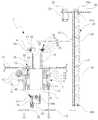
도 1은 본 발명에 따른 발전소밸브용 높이조절식 절삭가공장치의 정면개략도
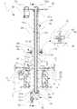
도 2는 본 발명에 따른 발전소밸브용 높이조절식 절삭가공장치의 분해상태를 도시한 종단면개략도
도 3은 본 발명에 따른 발전소밸브용 높이조절식 절삭가공장치의 조립상태를 도시한 종단면개략도
도 4는 도 3의 A-A'선의 단면개략도
도 5는 도 3의 B-B'선의 단면개략도
도 6은 본 발명에 따른 발전소밸브용 높이조절식 절삭가공장치의 절삭가공부를 확대한 상태의 종단면개략도
도 7은 본 발명에 따른 발전소밸브용 높이조절식 절삭가공장치의 가이드블럭이 우측으로 이동되어 절삭가공부의 회전반경이 확대되게 조절된 상태의 종단면개략도
도 8은 본 발명에 따른 발전소밸브용 높이조절식 절삭가공장치가 밸브의 헤드부 상면부에 동심원상으로 고정설치되면서 절삭비트가 시트링의 내경에 부합되는 회전반경으로 설치되어 절삭가공되는 상태의 단면개략도
도 9는 본 발명에 따른 발전소밸브용 높이조절식 절삭가공장치가 밸브의 헤드부 상면부에 동심원상으로 고정설치된 상태로 시트링의 절삭되는 폭만큼 가이드블럭이 좌측으로 점차적으로 이동되어 절삭가공부의 회전반경이 확대되고 시트링의 두께에 맞게 승강회동부가 하강이동되면서 절삭가공되는 상태의 단면개략도1 is a front schematic view of a height-adjustable cutting and working apparatus for a power plant valve according to the present invention;
Fig. 2 is a longitudinal sectional schematic view showing an exploded state of a height-adjustable cutting and working apparatus for a power plant valve according to the present invention.
3 is a longitudinal sectional schematic view showing an assembly state of a height-adjustable cutting and working apparatus for a power plant valve according to the present invention.
4 is a schematic cross-sectional view taken along line A-A '
5 is a schematic cross-sectional view taken along line B-B '
6 is a schematic longitudinal sectional view of a height-adjustable cutting apparatus for a power plant valve according to the present invention,
FIG. 7 is a schematic view of a longitudinal section of a height-adjustable cutting and processing apparatus for a power plant valve according to the present invention, in which a guide block is moved to the right,
8 is a view illustrating a state in which a height-adjustable cutting device for a power plant valve according to the present invention is installed in a concentric manner on a top surface of a head portion of a valve, and a cutting bit is installed at a turning radius corresponding to the inner diameter of the seat ring, Sectional schematic
FIG. 9 is a perspective view illustrating a state in which a height-adjustable cutting device for a power plant valve according to the present invention is fixed concentrically on an upper surface of a head portion of a valve, and the guide block is gradually moved to the left by a cutting width of the seat ring, A schematic cross-sectional view of the state in which the turning radius is enlarged and the elevating /
이하 본 발명에 따른 바람직한 구성을 도면에 의해 상세히 설명하면 다음과 같다.
Hereinafter, preferred embodiments of the present invention will be described in detail with reference to the drawings.
본 발명의 발전소밸브용 높이조절식 절삭가공장치(1)는 도 1 내지 9에 도시된 바와 같이 각종 발전소의 배관라인에 설치된 개폐식 밸브(3)의 시트링(7) 마모 및 손상시 손상된 시트링(7)을 간단하게 절삭가공하여 새로운 시트링(7)의 용이한 장착이 가능하도록 하는 절삭가공장치로서, 절삭가공될 밸브(3)의 헤드부(4) 상면부에 동심원상으로 고정설치되는 상하부가 개구된 통형상의 본체케이싱(5)이 구비되고 본체케이싱(5)의 외측면 상부에는 웜기어(11)가 회전작동되게 설치된 베이스본체부(2)와, 본체케이싱(5)의 내측에 회전되게 결합되는 원통형의 회전몸체(14)가 구비되고 회전몸체(14)의 상부 외주면에는 웜휠(16)이 고정설치되어 웜기어(11)와 기어물림되면서 회전되는 회전몸체부(13)와, 회전몸체(14)의 상부에 고정설치되는 가이드레일부재(19)가 구비되며 가이드레일부재(19)의 상면부에는 가운데부분에 수직상방으로 축케이싱관통관(25)이 관통개재된 가이드블럭(20)이 좌우이동되게 가이드결합되어 밸브(3)의 시트링(7) 직경에 따라 좌우위치조절되는 직경조절부(18)와, 상하로 긴 관형상으로 축케이싱관통관(25)과 회전몸체(14)를 관통하여 높이조절되게 설치되는 축케이싱(29)이 구비되고 축케이싱(29)의 내측에는 구동모터(30)로부터 구동력을 전달받아 회전되는 회동축(31)이 설치된 승강회동부(28)와, 축케이싱관통관(25)의 상부에 설치되면서 축케이싱(29) 외주면의 걸림요홈(36)에 걸림체결되는 볼플렌저(40)와 축케이싱(29) 외주면에 밀착지지되는 밀착판(41)이 구비되어 높이조절된 축케이싱(29)을 고정하는 높이고정부(39)와, 축케이싱(29)의 하부에 연결설치되며 회동축(31)으로부터 구동력을 전달받아 회전되면서 시트링(7)을 절삭가공하는 절삭비트(53)가 구비된 절삭가공부(48)로 구성되어 있다.
1 to 9, the height-adjustable cutting and working
상기 베이스본체부(2)는 도 1 내지 5, 7, 8, 9에 도시된 바와 같이 절삭가공될 발전소의 배관라인에 설치된 개폐식 밸브(3)의 상면부에 밸브(3)의 중심과 일치되게 동심원상으로 고정설치되는 부분으로, 절삭가공될 밸브(3)의 헤드부(4) 상면부에 동심원상으로 고정설치되는 상하부가 개구된 통형상의 본체케이싱(5)이 구비되고 본체케이싱(5)의 외측면 상부에는 웜기어(11)가 회전작동되게 설치되어 있되, 상기 본체케이싱(5)은 하면부에 수평으로 위치된 링형상의 장착플랜지(6)가 볼트 등으로 착탈되게 조립설치되도록 되어 있으며 상기 장착플랜지(6)는 도 8 및 9에 도시된 바와 같이 각종 발전소의 배관라인에 설치된 개폐식 밸브(3)의 헤드부(4) 내,외경과 동일한 내,외경을 지니게 가공되도록 되어 있어 각종 밸브(3)의 헤드부(4) 크기에 따라 장착플랜지(6)의 내,외경이 이에 부합되게 가공처리된 상태에서 본체케이싱(5)의 하면부에 장착플랜지(6)의 중심을 일치시킨 상태로 조립설치되고 장착플랜지(6)의 외주면은 밸브(3)의 헤드부(4) 외주면에 일부 용접처리되어 베이스본체부(2)가 밸브(3)의 헤드부(4) 상면부에 직교된 상태로 밸브(3)의 중심과 일치되게 동심원상으로 고정설치되도록 되어 있으며, 밸브(3) 시트링(7)의 절삭작업이 완료된 후에는 장착플랜지(6)와 밸브(3) 헤드부(4)의 용접된 부분을 떼어내 발전소밸브용 높이조절식 절삭가공장치(1)를 개폐식 밸브(3)로부터 분리하게 된다.
As shown in FIGS. 1 to 5, 7, 8 and 9, the
또한, 상기 개폐식 밸브(3)는 헤드부(4)의 상부 내측으로 투입장착되어 핸들에 의해 승강작동되면서 격판(27)의 배수공 내주면에 설치된 시트링(7)을 개폐하는 디스크부재(도시하지 않음)를 핸들과 함께 제거한 상태에서 밸브(3) 내측의 손상된 시트링(7)의 절삭가공처리가 이루어지도록 되어 있다.
The opening and
또한, 상기 본체케이싱(5)은 내주면에 하나 또는 복수개의 회전몸체베어링(8)이 상하 일정간격으로 설치되어 있고 회전몸체베어링(8)의 내측에는 회전몸체(14)가 관통 개재(介在)되어 회전가능하게 설치되며, 상기 본체케이싱(5)의 외주면 일측에는 웜기어설치대(9)가 고정 설치되어 있고 웜기어설치대(9)의 상부에는 전후수평방향으로 기어축(10)이 회전가능하게 설치되며 기어축(10)의 외주면에는 웜기어(11)가 일체로 축설되어 있고 기어축(10)의 일측끝단에는 조작핸들(12)이 연결장착되어 있어 도 8 및 9에 도시된 바와 같이 조작핸들(12)을 정역회전시킴에 따라 웜기어(11)가 회전되면서 웜기어(11)에 기어물림된 회전몸체(14)의 웜휠(16)을 회전구동시키도록 되어 있다.
One or a plurality of rotating
상기 회전몸체부(13)는 도 1 내지 5, 7, 8, 9에 도시된 바와 같이 내측에 관통설치되는 승강회동부(28)를 함께 회전시켜 밸브(3)의 시트링(7) 내주면을 따라 절삭가공부(48)에 의한 절삭가공이 이루어지도록 하는 부분으로, 본체케이싱(5)의 내측에 회전되게 결합되는 원통형의 회전몸체(14)가 구비되고 회전몸체(14)의 상부 외주면에는 웜휠(16)이 고정설치되어 웜기어(11)와 기어물림되면서 회전되도록 되어 있되, 상기 회전몸체(14)는 본체케이싱(5)의 내주면에 설치된 회전몸체베어링(8)의 내측에 수직으로 관통 개재되어 회전가능하게 설치되며 상부는 본체케이싱(5)의 상단부 외측으로 돌출된 상태로 돌출된 상부 외주면에 웜휠(16)이 일체로 고정설치되어 있어 베이스본체부(2)의 웜기어(11)와 기어물림된 상태로 조작핸들(12)에 의한 웜기어(11)의 회전시 웜휠(16)이 기어물림되어 회전몸체(14)가 일체로 회전구동되도록 되어 있고 회전몸체(14)의 하부끝부분 외주면에는 숫나사부가 형성되어 있어 마감너트(17)가 하방으로부터 나사체결되면서 회전몸체베어링(8)의 하면부 내곽부분에 밀착지지되어 회전몸체(14)의 유동 및 회전몸체(14)가 본체케이싱(5)의 상부쪽으로 빠져 이탈되는 것을 방지하도록 되어 있다.
1 to 5, 7, 8, and 9, the rotating
또한, 상기 회전몸체(14)는 내부에 수직으로 관통공(15)이 천공되어 있되 상기 관통공(15)은 도 5에 도시된 바와 같이 전후길이보다 좌우길이가 긴 장공형상으로 되어 있어 관통공(15)의 전후길이에 부합되는 외경을 지닌 승강회동부(28)의 축케이싱(29)이 관통공(15)의 내측에 부합되게 수직으로 관통된 상태로 관통공(15)을 따라 좌우로 이동가능하게 설치되도록 되어 있다.
As shown in FIG. 5, the
상기 직경조절부(18)는 도 1 내지 5, 7, 8, 9에 도시된 바와 같이 절삭가공되는 시트링(7)의 직경에 따라 승강회동부(28)의 좌우위치를 조절하여 절삭가공부(48)의 회전반경이 확대 또는 축소되게 조절하는 부분으로, 회전몸체(14)의 상부에 고정설치되는 가이드레일부재(19)가 구비되며 가이드레일부재(19)의 상면부에는 가운데부분에 수직상방으로 축케이싱관통관(25)이 관통개재된 가이드블럭(20)이 좌우이동되게 가이드결합되어 밸브(3)의 시트링(7)의 직경에 따라 좌우위치조절되도록 되어 있되, 상기 가이드레일부재(19)는 수평으로 위치된 판형상으로 회전몸체(14)의 상부에 일체로 고정설치되어 함께 회전되도록 되어 있으며 가운데부분에는 회전몸체(14)의 관통공(15)과 동일한 크기와 형상을 지닌 상측연통공(22)이 천공되어 있어 관통공(15)과 상측연통공(22)이 상하 연통되게 설치되도록 되어 있고 가이드레일부재(19)의 상면부에는 전후양측에 레일홈(23)이 좌우수평으로 형성되어 있어 전후측 레일홈(23) 사이에 가이드블럭(20)이 부합되게 가이드결합되면서 좌우이동되도록 되어 있으며 좌우양측 끝단에는 각각 볼트체결편(24)이 상방으로 돌출되게 고정설치되어 있고 좌우측 볼트체결편(24)의 가운데부분에는 각각 암나사공이 천공되어 있어 좌우수평으로 위치된 좌우측 조절볼트(21)가 나사체결식으로 관통개재되면서 가이드블럭(20)의 좌우양측끝단에 맞닿아 지지되도록 되어 있으며 도 7 및 9에 도시된 바와 같이 좌우측 조절볼트(21)를 풀거나 조임에 따라 가이드블럭(20)의 좌우위치가 조절되면서 승강회동부(28)의 좌우위치가 함께 조절되고 이에 따라 절삭가공되는 시트링(7)의 직경에 맞게 승강회동부(28)의 하부에 연결설치되는 절삭가공부(48)의 회전반경이 확대 또는 축소되게 조절되도록 되어 있다.
As shown in FIGS. 1 to 5, 7, 8, and 9, the
또한, 상기 축케이싱관통관(25)은 가이드블럭(20)의 가운데부분에 수직상방으로 관통 개재된 상태로 일체로 고정설치되어 가이드블럭(20)과 함께 좌우이동되도록 되어 있으며 내경은 승강회동부(28)의 축케이싱(29)에 부합되는 내경을 지니고 있어 내측에 축케이싱(29)이 부합되게 관통되도록 되어 있고, 상기 축케이싱관통관(25)의 상단부 외주면에는 플랜지판(26)이 고정설치되어 있으며 플랜지판(26)의 상면부에는 높이고정부(39)의 볼플렌저(40)와 밀착판(41)이 설치되도록 되어 있다.
The
상기 승강회동부(28)는 도 1 내지 9에 도시된 바와 같이 밸브(3)에 설치된 시트링(7)의 설치위치 및 시트링(7)의 두께에 따라 승강작동되면서 절삭가공부(48)에 구동력을 전달하여 회동되게 하는 부분으로, 상하로 긴 관형상으로 축케이싱관통관(25)과 회전몸체(14)를 관통하여 높이조절되게 설치되는 축케이싱(29)이 구비되고 축케이싱(29)의 내측에는 구동모터(30)로부터 구동력을 전달받아 회전되는 회동축(31)이 설치되어 있되, 상기 축케이싱(29)은 상하부가 개구된 원형의 관으로 되어 있고 외경은 축케이싱관통관(25)의 내경에 부합되도록 되어 있어 축케이싱관통관(25)과 회전몸체(14)의 관통공(15)을 관통하여 본체케이싱(5)의 하부 외측으로 돌출되도록 되어 있으며 내측 상하부에는 각각 축베어링(32a)(32b)이 설치되어 있어 축베어링(32a)(32b)의 내측에 회동축(31)이 관통개재되면서 원활하게 회전되도록 되어 있고 축케이싱(29)의 상면부에는 모터설치판(33)이 수평으로 고정설치되어 있으며 상기 모터설치판(33)에는 구동모터(30)가 장착되어 회동축(31)에 구동력을 전달하도록 되어 있다.
1 to 9, the lifting and lowering
또한, 상기 회동축(31)은 축케이싱(29)의 축베어링(32a)(32b) 내측에 관통 개재되어 있고 상,하부끝단이 축케이싱(29)의 상,하부 외측으로 돌출된 상태로 각각 피동풀리(34a)(34b)가 축설되어 있어 상측 피동풀리(34a)는 구동모터(30)의 축에 축설된 구동풀리(35)와 벨트 등으로 연결되며 하측 피동풀리(34b)는 절삭가공부(48)의 절삭축(50) 상부끝단에 축설된 연결풀리(51)와 벨트 등으로 연결되어 구동모터(30)로부터의 구동력이 회동축(31)을 거쳐 절삭축(50)으로 전달되도록 되어 있다.
The
또한, 상기 축케이싱(29)은 외주면 일측에 상하 일직선상으로 다수개의 걸림요홈(36)이 형성되어 있어 높이고정부(39)에 구비된 볼플렌저(40)의 볼이 걸림요홈(36)에 삽입되어 일시 걸림체결되도록 되면서 상하 위치조절되도록 되어 있고 축케이싱(29)의 외주면 타측에는 높이고정부(39)의 밀착판(41)이 밀착지지된 상태로 맞닿아 상하 높이조절된 축케이싱(29)의 높이가 고정된 상태로 유지되도록 되어 있다.
The
한편, 상기 승강회동부(28)는 도 7에 도시된 바와 같이 축케이싱(29)의 상면부에 고정설치된 모터설치판(33)의 상부에 상하 일정간격 이격된 상태로 거치대(37)가 설치되고 거치대(37)의 상면부에는 수직하방으로 구동모터(30)가 고정설치되며 구동모터(30)의 축은 거치대(37)를 관통한 상태로 회동축(31)의 상부끝부분과 커플러(38)를 통해 연결되어 구동력을 직접적으로 전달받도록 할 수 있다.
7, the lifting and lowering
또한, 상기 축케이싱(29)은 외측면에 상하 일직선상으로 키홈(54)이 형성되어 있고 상기 축케이싱관통관(25)은 내주면에 상하 일직선상으로 키돌기(55)가 돌출형성되어 있어 축케이싱관통관(25)을 관통하는 축케이싱(29)의 키홈(54)에 키돌기(55)가 부합되게 삽입되면서 축케이싱(29)이 헛돌지 않도록 되어 있다.
A
상기 높이고정부(39)는 도 1 내지 3, 7, 8, 9에 도시된 바와 같이 밸브(3)의 크기 및 시트링(7)의 가공에 따라 상하 높이조절되는 축케이싱(29)을 고정하는 부분으로, 축케이싱관통관(25)의 상부에 설치되면서 축케이싱(29) 외주면의 걸림요홈(36)에 걸림체결되는 볼플렌저(40)와 축케이싱(29) 외주면에 밀착지지되는 밀착판(41)이 구비되어 높이조절된 축케이싱(29)을 고정하도록 되어 있되, 상기 볼플렌저(40)는 내장설치된 스프링에 의해 선단부에 위치된 볼이 탄성지지되는 것으로 외주면에는 숫나사부가 형성되어 있어 수평으로 눕혀진 상태로 축케이싱관통관(25)의 플랜지판(26) 상면부 일측에 수직으로 설치된 플렌저설치대(42)에 나사체결식으로 관통 개재되면서 축케이싱(29)의 외주면 일측에 좌우 위치조절되게 설치되며 상기 볼플렌저(40)의 볼은 축케이싱(29)의 외주면 일측에 상하 일정간격으로 형성된 다수개의 걸림요홈(36)에 삽입되어 걸림체결되면서 상하 높이조절된 축케이싱(29)의 위치가 고정되도록 되어 있고, 상기 밀착판(41)은 라운드진 호형상의 판으로 수직으로 세워져 있고 일측 내주면에는 고무재질로 된 밀착패드(43)가 고정부착되어 있으며 축케이싱관통관(25)의 플랜지판(26) 상면부 타측에 수직으로 고정설치된 밀착판설치대(44)를 수평으로 관통하여 나사체결되는 조임볼트(45)의 일측끝단이 밀착판(41)의 타측면 가운데부분에 자유회전가능하게 연결설치되어 있어 조임볼트(45)를 풀거나 조임에 따라 밀착판(41)이 좌우이동되면서 상하 높이조절된 축케이싱(29)의 타측 외주면에 밀착지지되어 상하유동되는 것을 방지하도록 되어 있다.
1 to 3, 7, 8 and 9, the heightening and
또한, 상기 플렌저설치대(42)는 하부에 플렌저가이드대(46)가 상하 가이드결합된 상태로 연결설치되어 상하 위치이동가능하게 설치되며 플렌저설치대(42)에는 수직으로 높이조절볼트(47)가 나사체결식으로 관통 개재되면서 높이조절볼트(47)의 하단부는 플렌저가이드대(46)의 상면부에 자유회전가능하게 연결설치되어 있어 상기 높이조절볼트(47)를 풀거나 조임에 따라 플렌저설치대(42)가 상하 높이조절되면서 볼플렌저(40)에 의해 걸림체결된 축케이싱(29)을 시트링(7)의 가공두께에 부합되게 미세 높이조절 가능하도록 되어 있다.
The
상기 절삭가공부(48)는 도 1 내지 4, 6, 7, 8, 9에 도시된 바와 같이 밸브(3)의 시트링(7)을 절삭가공하여 제거하는 부분으로, 상기 축케이싱(29)의 하부에 연결설치되며 회동축(31)으로부터 구동력을 전달받아 회전되면서 시트링(7)을 절삭가공하는 절삭비트(53)가 구비되어 있되, 상기 절삭가공부(48)는 축케이싱(29)의 하단부에 복수개의 볼트에 의해 고정설치되는 절삭하우징(49)이 구비되어 있고 절삭하우징(49)의 내부 일측에는 수직으로 절삭축(50)이 회전가능하게 관통 개재되어 있으며 절삭축(50)의 상부끝단에는 연결풀리(51)가 축설되어 있고 절삭하우징(49)의 상부에는 풀리설치홈(52)이 형성되어 있어 회동축(31)의 하부끝단에 축설된 하측 피동풀리(34b)와 절삭축(50)의 연결풀리(51)가 풀리설치홈(52) 내측에 위치된 상태에서 통상의 벨트 등을 통해 연결되어 회동축(31)으로부터의 구동력이 절삭축(50)으로 전달되어 회전되도록 되어 있다.
1 to 4, 6, 7, 8 and 9, the
또한, 상기 절삭축(50)은 하부가 절삭하우징(49)을 관통하여 하부 외측으로 돌출되게 설치되며 절삭축(50)의 하부끝단에는 다수개의 초경금속편이나 금강석편이 고정부착된 절삭비트(53)가 연결장착되도록 되어 있어 도 8에 도시된 바와 같이 절삭축(50)의 회전에 따라 절삭비트(53)가 함께 고속으로 회전되면서 마모 손상된 시트링(7)을 내경쪽에서 외경쪽으로 절삭가공하여 제거하도록 되어 있되, 상기 회전몸체부(13)의 회전몸체(14)를 회전시킴에 따라 승강회동부(28)가 회전몸체(14)의 중심부를 축으로 회전되고 절삭가공부(48)가 이와 함께 회전되어 시트링(7)의 내경에 부합되는 회전반경으로 절삭비트(53)가 공전되면서 절삭가공되도록 되어 있고, 상기 절삭비트(53)의 회전반경 내에 맞닿는 시트링(7)의 내경부분이 절삭가공된 후에는 승강회동부(28)를 일정거리 하강이동시키면서 일정두께를 지닌 시트링(7)의 내경부분을 상하 전체적으로 절삭가공하게 되며, 상기와 같이 절삭비트(53)의 회전반경 내에 맞닿는 시트링(7)의 내경부분을 상하 전체적으로 절삭가공한 후에는 도 9에 도시된 바와 같이 가이드블럭(20)을 좌우방향으로 일정거리 이동시켜 절삭가공부(48)의 회전반경이 확대되도록 하는 방식으로 시트링(7)을 내경쪽에서 외경쪽으로 일정폭만큼 점차적으로 절삭가공하도록 되어 있다.
The
이하 본 발명의 작용은 다음과 같다.Hereinafter, the operation of the present invention will be described.
본 발명에 따른 발전소밸브용 높이조절식 절삭가공장치(1)를 사용하여 각종 발전소의 배관라인에 설치된 개폐식 밸브(3)의 마모 손상된 시트링(7)을 간단하게 절삭가공하여 제거하고자 하는 경우에는, 먼저 도 8에 도시된 바와 같이 절삭가공처리할 밸브(3)의 헤드부(4)에 설치된 핸들에 의해 승강작동되는 디스크부재(도시하지 않음)를 제거하고 밸브(3)의 헤드부(4) 내,외경에 부합되는 내,외경을 지니도록 가공된 장착플랜지(6)를 다수개의 볼트를 통해 본체케이싱(5)의 하면부에 중심을 일치시킨 상태로 수평으로 조립설치하면서 장착플랜지(6)의 외주면은 밸브(3)의 헤드부(4)에 일부 용접처리하는 방식으로 베이스본체부(2)가 밸브(3)의 헤드부(4) 상면부에 직교된 상태로 밸브(3)의 중심과 일치되게 동심원상으로 고정설치되도록 한다.
In the case where the
다음으로, 상기 축케이싱(29)에 일정한 하중을 가하여 축케이싱관통관(25)과 회전몸체(14)의 관통공(15)을 통해 하강이동시키면서 밸브(3)의 내측에 구비된 격판(28)의 시트링(7)에 부합되는 높이까지 절삭가공부(48)의 절삭비트(53)를 하강이동시킨 다음 축케이싱(29)의 하강이동을 정지시키면 높이고정부(39)에 구비된 볼플렌저(40)의 볼이 해당 높이에 형성된 축케이싱(29)의 걸림요홈(36)에 삽입되어 일시 걸림체결된 상태를 유지하며 이 상태에서 높이고정부(39)의 조임볼트(45)를 조여 밀착판(41)의 밀착패드(43)가 축케이싱(29)의 외주면 타측에 밀착지지되면서 축케이싱(29)이 상하 유동되지 않게 고정되도록 하며, 도 7에 도시된 바와 같이 직경조절부(18)의 좌우측 조절볼트(21)를 풀거나 조여 가이드블럭(20)의 좌우위치를 조절하면서 회전몸체(14)의 장공으로 된 관통공(15)을 따라 승강회동부(28)의 좌우위치가 함께 조절되게 하여 절삭비트(53)의 하단부가 시트링(7)의 내주면 상단부에 맞닿도록 위치시킨 후 구동모터(30)를 작동시켜 회동축(31)이 회전되도록 하고 회동축(31)으로부터의 구동력이 절삭축(50)으로 전달되어 절삭비트(53)가 회전되면서 이와 맞닿는 시트링(7)을 절삭가공하며 이와 함께 도 8에 도시된 바와 같이 본체케이싱(5)의 외주면 일측에 설치된 웜기어설치대(9)의 조작핸들(12)을 정역회전시켜 웜기어(11)에 기어물림된 회전몸체(14)의 웜휠(16)이 회전구동되면서 회전몸체(14)를 회전시키고 회전몸체(14)의 내측에 관통 설치된 승강회동부(28)가 회전몸체(14)의 중심부를 축으로 회전하여 절삭가공부(48)의 절삭비트(53)가 자전과 동시에 시트링(7)의 내경을 따라 동일한 회전반경으로 공전되어 시트링(7)의 내주면을 일정두께와 폭으로 절삭가공하게 된다.
A predetermined load is applied to the
상기와 같이 절삭비트(53)의 회전반경 내에 맞닿는 시트링(7)의 내경부분이 절삭가공된 후에는 높이고정부(39)의 조임볼트(45)를 풀어 축케이싱(29)으로부터 밀착판(41)을 일정간격 이격시킨 상태에서 플렌저설치대(42)의 높이조절볼트(47)를 정역회전시켜 볼플렌저(40)가 하강이동되게 조절하여 승강회동부(28)를 일정거리 하강이동시킨 다음 밀착판(41)으로 축케이싱(29)을 조임고정하고, 절삭가공부(48)의 절삭비트(53)를 자전시키면서 회전몸체(14)를 통해 공전시켜 일정두께를 지닌 시트링(7)의 내경부분을 상하 전체적으로 절삭가공하며, 상기와 같이 절삭비트(53)의 회전반경 내에 맞닿는 시트링(7)의 내경부분을 상하 전체적으로 절삭가공한 후에는 도 9에 도시된 바와 같이 가이드블럭(20)을 좌우방향으로 일정거리 이동시켜 절삭가공부(48)의 회전반경이 확대되도록 하는 방식으로 시트링(7)을 내경쪽에서 외경쪽으로 일정폭만큼 점차적으로 절삭가공하여 밸브(3)의 격판(28)에 고정장착된 시트링(7)을 완전히 절삭 제거하게 된다.
After the inner diameter portion of the
상기 밸브(3)의 시트링(7)이 절삭제거된 후에는 밸브(3)의 헤드부(4)에 용접부착된 장착플랜지(6)를 떼어내 발전소밸브용 절삭가공장치(1)를 밸브(3)로부터 분리시킨 후 새로운 시트링(7)을 밸브(3)의 격판(28)에 고정장착하여 밸브(3)의 보수작업을 완료하게 된다.
After the
1. 절삭가공장치2. 베이스본체부
3. 밸브4. 헤드부
5. 본체케이싱6. 장착플랜지
7. 시트링8. 회전몸체베어링
9. 웜기어설치대10. 기어축
11. 웜기어12. 조작핸들
13. 회전몸체부14. 회전몸체
15. 관통공16. 웜휠
17. 마감너트18. 직경조절부
19. 가이드레일부재20. 가이드블럭
21. 조절볼트22. 상측연통공
23. 레일홈24. 볼트체결편
25. 축케이싱관통관26. 플랜지판
27. 격판28. 승강회동부
29. 축케이싱30. 구동모터
31. 회동축32a, 32b. 축베어링
33. 모터설치판34a, 34b. 피동풀리
35. 구동풀리36. 걸림요홈
37. 거치대38. 커플러
39. 높이고정부40. 볼플렌저
41. 밀착판42. 플렌저설치대
43. 밀착패드44. 밀착판설치대
45. 조임볼트46. 플렌저가이드대
47. 높이조절볼트48. 절삭가공부
49. 절삭하우징50. 절삭축
51. 연결풀리52. 풀리설치홈
53. 절삭비트54. 키홈
55. 키돌기1. Cutting
3.
5.
7.
9.
11.
13.
15. Through
17. Finishing
19.
21.
23.
25. Axial
27.
29.
31.
33.
35. Driving
37.
39.
41. Adhering
43.
45. Fastening
47.
49. Cutting
51. Connecting
53. Cutting
55. Key projection
Claims (7)
Translated fromKoreanA tubular main body casing 5 having upper and lower portions opened and fixed concentrically on the upper surface of the head portion 4 of the valve 3 to be cut is provided and the worm gear 11 And a cylindrical rotating body 14 rotatably coupled to the inside of the main body casing 5 and a worm wheel 16 is provided on the outer peripheral surface of the upper portion of the rotating body 14 And a guide rail member 19 fixedly installed on the upper portion of the rotary body 14 and fixed to the upper surface of the guide rail member 19, A guide block 20 is vertically upwardly and vertically upwardly inserted into the center of the guide block 20 and is guided in the left and right direction so as to be horizontally moved according to the diameter of the seat ring 7 of the valve 3, (18), an axial casing pipe (25) and a rotating body (14) in a vertically long tubular shape A lifting and rotating unit 28 provided with a shaft casing 29 installed to be adjustable in height and provided with a pivoting shaft 31 which is rotated by receiving a driving force from a driving motor 30 is provided inside the shaft casing 29, A ball plunger 40 which is installed on the upper portion of the casing pipe 25 and which is engaged with the engaging groove 36 of the outer circumferential surface of the shaft casing 29 and the urging plate 41 which is tightly supported on the outer circumferential surface of the shaft casing 29 The seat ring 7 is connected to the lower portion of the shaft casing 29 and is rotated by receiving the driving force from the rotary shaft 31 to cut the seat ring 7, And a cutting edge (48) provided with a cutting bit (53) to be machined.
2. The apparatus according to claim 1, wherein a ring-shaped mounting flange (6) having an inner diameter equal to the inner diameter of the head part (4) of the valve (3) One or a plurality of rotating body bearings 8 are installed at regular intervals on the inner circumferential surface of the body casing 5 and a rotating body 14 is inserted through the inside of the rotating body bearing 8 to be rotatable. A gear shaft 10 is rotatably installed horizontally in the front and rear of the worm gear mounting base 9 and a worm gear 11 is integrally formed on the outer circumferential surface of the gear shaft 10. The worm gear mounting base 9, And an operation handle 12 is connected to one end of the gear shaft 10 so that the worm gear 11 is rotated in accordance with the forward and reverse rotation of the operation handle 12, (16) of the rotor (14) Height adjustable cutting device for a valve.
3. The rotary compressor according to claim 1 or 2, wherein the rotary body (14) is vertically penetrated through the inside of a rotary body bearing (8) provided on the inner circumferential surface of the body casing (5) 5, a worm wheel 16 is integrally fixed to an upper outer circumferential surface protruding from the upper end portion of the rotary body 14, and a male screw portion is formed on the outer circumferential surface of the lower end portion of the rotary body 14, And a through hole 15 is vertically formed in the rotating body 14 so that the through hole 15 is formed in the left and right sides of the rotating body 14, A cylindrical shaft casing 29 having an outer diameter conforming to the longitudinal length of the through hole 15 is formed in the elongated hole so that the through hole 15 is vertically penetrated so as to be aligned with the inside of the through hole 15 Which is installed so as to be movable left and right Height adjustable cutting device for a power plant, characterized in a valve.
2. The apparatus according to claim 1, wherein the guide rail member (19) is horizontally positioned and fixed to the upper part of the rotating body (14) and rotates together with the through hole (15) of the rotating body An upper communication hole 22 having the same size and shape is perforated so as to be vertically communicated. A rail groove 23 is horizontally formed on both front and rear sides of the upper surface portion of the guide rail member 19 so that front and rear side rail grooves 23 The guide block 20 is guided in the left and right directions, and bolt fastening pieces 24 are fixedly installed on both left and right ends of the guide block 20 so as to protrude upward. The left and right bolt fastening pieces 24 are horizontally The right and left adjustment bolts 21 are inserted into the guide block 20 while being inserted into the guide block 20 while being screwed with each other so that the right and left positions of the guide block 20 are adjusted (28) Height adjustment valve for power plant, characterized in that the horizontal position is adjusted with expression cutting device.
[2] The ball screw according to claim 1, wherein the ball plunger (40) has a ball disposed at a distal end portion thereof by a spring installed therein and is elastically supported, and a male screw portion is formed on an outer circumferential surface thereof, And the ball of the ball plunger 40 is installed on one side of the outer circumferential surface of the shaft casing 29 while being inserted into the flange mounting base 42 provided on one side of the upper surface of the flange plate 26, (Not shown) is inserted into and engaged with a plurality of latching grooves 36 formed at upper and lower predetermined intervals on one side of the outer circumferential surface of the latching plate 29. The latching plate 41 is vertically erected as a plate having a rounded chevron shape, One end of the fastening bolt 45, which is horizontally threaded and fastened to the fastening plate mounting base 44 fixedly attached to the upper surface of the flange plate 26 of the shaft casing pipe 25, (41) And the tightening bolt 45 is tightened and tightened so that the tightening plate 41 is moved in the left and right direction and tightly supported on the outer circumferential surface of the other side of the shaft casing 29 whose height has been adjusted. Height adjustable cutting device for power plant valves.
6. The apparatus according to claim 5, wherein the flange mounting base (42) is connected to the lower flange guide base (46) in a state of being vertically guided and is vertically moved. The flange mounting base (42) The lower end of the height adjusting bolt 47 is connected to the upper surface of the flange guide base 46 so as to freely rotate so that the height adjusting bolt 47 is loosened And the height of the ball plunger (40) can be adjusted while the height of the flange mounting base (42) is adjusted according to the tightening.
The cutting insert according to claim 1, wherein the cutting work (48) comprises a cutting housing (49) fixed to a lower end of a shaft casing (29) by a plurality of bolts, A connecting pulley 51 is installed at the upper end of the cutting shaft 50 and a lower portion of the cutting shaft 50 is inserted through the cutting housing 49 And a pulley mounting groove 52 is formed in an upper portion of the cutting housing 49. A lower driven pulley 34b and a lower driven pulley 34b are provided at the lower end of the rotary shaft 31, The connecting pulley 51 of the cutting shaft 50 is connected to the inside of the pulley mounting groove 52 via the belt so that the driving force from the rotating shaft 31 is transmitted to the cutting shaft 50 and is rotated Height adjustable cutting device for power plant valves.
Priority Applications (1)
| Application Number | Priority Date | Filing Date | Title |
|---|---|---|---|
| KR1020150160217AKR20170056862A (en) | 2015-11-16 | 2015-11-16 | The cutting machine for a power plant valve |
Applications Claiming Priority (1)
| Application Number | Priority Date | Filing Date | Title |
|---|---|---|---|
| KR1020150160217AKR20170056862A (en) | 2015-11-16 | 2015-11-16 | The cutting machine for a power plant valve |
Publications (1)
| Publication Number | Publication Date |
|---|---|
| KR20170056862Atrue KR20170056862A (en) | 2017-05-24 |
Family
ID=59051279
Family Applications (1)
| Application Number | Title | Priority Date | Filing Date |
|---|---|---|---|
| KR1020150160217AAbandonedKR20170056862A (en) | 2015-11-16 | 2015-11-16 | The cutting machine for a power plant valve |
Country Status (1)
| Country | Link |
|---|---|
| KR (1) | KR20170056862A (en) |
Cited By (5)
| Publication number | Priority date | Publication date | Assignee | Title |
|---|---|---|---|---|
| CN110303170A (en)* | 2019-07-14 | 2019-10-08 | 南京湛泸科技有限公司 | A kind of gate valve seat ring cutter device |
| KR20200118708A (en) | 2019-04-08 | 2020-10-16 | 주식회사 삼신 | Apparatus for cutting seat ring of power plant valve |
| CN111993286A (en)* | 2020-09-15 | 2020-11-27 | 江苏富技腾机电科技有限公司 | Multifunctional cutter head and cutting method thereof |
| KR20210003601A (en) | 2019-07-02 | 2021-01-12 | 삼신밸브기술(주) | Spindle device for seat ring cutter of power plant valves |
| CN118002830A (en)* | 2024-03-26 | 2024-05-10 | 山东德奥密封技术有限公司 | Cylinder seal processing equipment |
- 2015
- 2015-11-16KRKR1020150160217Apatent/KR20170056862A/ennot_activeAbandoned
Cited By (6)
| Publication number | Priority date | Publication date | Assignee | Title |
|---|---|---|---|---|
| KR20200118708A (en) | 2019-04-08 | 2020-10-16 | 주식회사 삼신 | Apparatus for cutting seat ring of power plant valve |
| KR20210003601A (en) | 2019-07-02 | 2021-01-12 | 삼신밸브기술(주) | Spindle device for seat ring cutter of power plant valves |
| CN110303170A (en)* | 2019-07-14 | 2019-10-08 | 南京湛泸科技有限公司 | A kind of gate valve seat ring cutter device |
| CN110303170B (en)* | 2019-07-14 | 2024-05-17 | 南京湛泸科技有限公司 | Gate valve seat ring cutting device |
| CN111993286A (en)* | 2020-09-15 | 2020-11-27 | 江苏富技腾机电科技有限公司 | Multifunctional cutter head and cutting method thereof |
| CN118002830A (en)* | 2024-03-26 | 2024-05-10 | 山东德奥密封技术有限公司 | Cylinder seal processing equipment |
Similar Documents
| Publication | Publication Date | Title |
|---|---|---|
| KR101819974B1 (en) | The cutting machine for a power plant valve | |
| KR20170056862A (en) | The cutting machine for a power plant valve | |
| US4050836A (en) | Portable field machine for cutting, grinding and lapping valve seats | |
| KR101183132B1 (en) | Apparatus for boring of valve sheet | |
| KR100943767B1 (en) | Portable flange facer capable of optionally adjusting serration roughness | |
| CA2591455A1 (en) | Air-operated end prep machine | |
| CN101767214A (en) | Special equipment for machining inner bore of primary loop piping elbow in nuclear power plant | |
| KR20200007571A (en) | Apparatus for cutting seat ring of power plant valve | |
| KR20110007373U (en) | The cutting machine for large pipe in piping work | |
| US4106880A (en) | Portable field machine for cutting, grinding and lapping valve seats | |
| KR100372272B1 (en) | Apparatus for replace a ring in opening/closing valve equipped in ducts or pipes for passage of fluid | |
| CN109290734A (en) | A kind of field repair equipment of large apertures | |
| US6990878B2 (en) | Radial feed facing head for boring bar | |
| KR101895539B1 (en) | Manufacturing Apparatus of Differential Gear Case used Machining Center | |
| US8282444B2 (en) | Overlay sander | |
| US20140014381A1 (en) | Machining apparatus | |
| KR100655919B1 (en) | Belt type turret tool stand | |
| KR102175173B1 (en) | Apparatus for cutting seat ring of power plant valve | |
| KR20170101564A (en) | A processing apparatus for flange | |
| KR102205500B1 (en) | Spindle device for seat ring cutter of power plant valves | |
| CN111804958B (en) | A drilling machine auxiliary device | |
| KR101203967B1 (en) | Device for repairing valve | |
| CN112974890B (en) | Deep hole molded line boring device | |
| KR20130115597A (en) | Spindle overhead installation and spindle reuse method | |
| US4856390A (en) | Valve reseater apparatus and method |
Legal Events
| Date | Code | Title | Description |
|---|---|---|---|
| A201 | Request for examination | ||
| PA0109 | Patent application | Patent event code:PA01091R01D Comment text:Patent Application Patent event date:20151116 | |
| PA0201 | Request for examination | ||
| E902 | Notification of reason for refusal | ||
| PE0902 | Notice of grounds for rejection | Comment text:Notification of reason for refusal Patent event date:20160525 Patent event code:PE09021S01D | |
| N231 | Notification of change of applicant | ||
| PN2301 | Change of applicant | Patent event date:20160727 Comment text:Notification of Change of Applicant Patent event code:PN23011R01D | |
| E701 | Decision to grant or registration of patent right | ||
| PE0701 | Decision of registration | Patent event code:PE07011S01D Comment text:Decision to Grant Registration Patent event date:20161101 | |
| PG1501 | Laying open of application | ||
| PC1904 | Unpaid initial registration fee |