KR20170052051A - Touch sensing method, touch sensing controller and touch sensing device having the same - Google Patents
Touch sensing method, touch sensing controller and touch sensing device having the sameDownload PDFInfo
- Publication number
- KR20170052051A KR20170052051AKR1020150153974AKR20150153974AKR20170052051AKR 20170052051 AKR20170052051 AKR 20170052051AKR 1020150153974 AKR1020150153974 AKR 1020150153974AKR 20150153974 AKR20150153974 AKR 20150153974AKR 20170052051 AKR20170052051 AKR 20170052051A
- Authority
- KR
- South Korea
- Prior art keywords
- sensing
- touch
- signal
- driving
- frequency
- Prior art date
- Legal status (The legal status is an assumption and is not a legal conclusion. Google has not performed a legal analysis and makes no representation as to the accuracy of the status listed.)
- Granted
Links
Images


Classifications
- G—PHYSICS
- G06—COMPUTING OR CALCULATING; COUNTING
- G06F—ELECTRIC DIGITAL DATA PROCESSING
- G06F3/00—Input arrangements for transferring data to be processed into a form capable of being handled by the computer; Output arrangements for transferring data from processing unit to output unit, e.g. interface arrangements
- G06F3/01—Input arrangements or combined input and output arrangements for interaction between user and computer
- G06F3/03—Arrangements for converting the position or the displacement of a member into a coded form
- G06F3/041—Digitisers, e.g. for touch screens or touch pads, characterised by the transducing means
- G06F3/044—Digitisers, e.g. for touch screens or touch pads, characterised by the transducing means by capacitive means
- G—PHYSICS
- G06—COMPUTING OR CALCULATING; COUNTING
- G06F—ELECTRIC DIGITAL DATA PROCESSING
- G06F3/00—Input arrangements for transferring data to be processed into a form capable of being handled by the computer; Output arrangements for transferring data from processing unit to output unit, e.g. interface arrangements
- G06F3/01—Input arrangements or combined input and output arrangements for interaction between user and computer
- G06F3/03—Arrangements for converting the position or the displacement of a member into a coded form
- G06F3/041—Digitisers, e.g. for touch screens or touch pads, characterised by the transducing means
- G06F3/0416—Control or interface arrangements specially adapted for digitisers
- G06F3/0418—Control or interface arrangements specially adapted for digitisers for error correction or compensation, e.g. based on parallax, calibration or alignment
Landscapes
- Engineering & Computer Science (AREA)
- General Engineering & Computer Science (AREA)
- Theoretical Computer Science (AREA)
- Human Computer Interaction (AREA)
- Physics & Mathematics (AREA)
- General Physics & Mathematics (AREA)
- Electronic Switches (AREA)
- Position Input By Displaying (AREA)
Abstract
Translated fromKoreanDescription
Translated fromKorean본 발명은 터치 센싱 방법, 터치 센싱 콘트롤러 및 이를 갖는 터치 센싱장치 에 관한 것으로, 보다 상세하게는 서로 인접하는 센싱전극에서 차동적으로 수신된 센싱신호들을 근거로 터치 발생 여부를 판별하는 터치 센싱 방법, 터치 센싱 콘트롤러 및 이를 갖는 터치 센싱장치에 관한 것이다.The present invention relates to a touch sensing method, a touch sensing controller, and a touch sensing apparatus having the touch sensing apparatus. More particularly, the present invention relates to a touch sensing method for determining whether a touch is generated based on sensing signals differentially received from adjacent sensing electrodes, And a touch sensing apparatus having the touch sensing controller.
터치 센싱 장치는 기계식 버튼, 키패드, 키보드, 및 포인팅 장치의 필요성을 감소시키거나 없앰으로써 사용자가 전자 시스템 및 디스플레이와 편리하게 인터페이스할 수 있게 해준다. 예를들어, 사용자는 아이콘에 의해 식별되는 위치에서 디스플레이 중인 터치 스크린을 간단히 터치함으로써 복잡한 일련의 명령어들을 실행할 수 있다.The touch sensing device allows the user to conveniently interface with electronic systems and displays by reducing or eliminating the need for mechanical buttons, keypads, keyboards, and pointing devices. For example, a user can execute a complex series of commands by simply touching the touch screen being displayed at the location identified by the icon.
예를들어, 저항 방식, 적외선 방식, 정전용량 방식, 표면 탄성파 방식, 전자기 방식, 근접장 이미징(near field imaging) 방식 등을 비롯한, 터치 센싱 장치를 구현하는 몇가지 유형의 기술이 있다. 정전용량 방식의 터치 센싱 장치는 다수의 응용에서 잘 동작하는 것으로 밝혀졌다. 많은 터치 센싱 장치에서, 센서 내의 전도성 물체가 사용자의 손가락과 같은 전도성 터치 도구와 용량적으로 결합될 때 입력이 센싱된다. 일반적으로, 2개의 전기 전도성 부재가 실제로 터치하는 일없이 서로 근접하게 될 때마다, 이들 사이에 커패시턴스가 형성된다. 정전용량 방식의 터치 센싱 장치의 경우에, 손가락과 같은 물체가 터치 센싱 표면에 접근할 때, 물체와 아주 근접해 있는 센싱 지점 사이에 작은 커패시턴스가 형성된다. 각각의 센싱 지점에서 커패시턴스의 변화를 검출하고 센싱 지점의 위치에 유의함으로써, 센싱 회로는 다수의 물체를 인식하고 물체가 터치 표면에 걸쳐 움직일 때 물체의 특성을 결정할 수 있다.There are several types of techniques for implementing touch sensing devices, including, for example, resistive, infrared, capacitive, surface acoustic, electromagnetic, near field imaging, and the like. Capacitive touch sensing devices have been found to work well in many applications. In many touch sensing devices, the input is sensed when a conductive object in the sensor is capacitively coupled to a conductive touch tool, such as a user's finger. Generally, a capacitance is formed between two electrically conductive members whenever they are brought close to each other without actually touching them. In the case of capacitive touch sensing devices, when an object such as a finger approaches the touch sensing surface, a small capacitance is formed between the sensing object and the sensing point. By sensing the change in capacitance at each sensing point and taking note of the location of the sensing point, the sensing circuit can recognize a number of objects and determine the characteristics of the object as it moves across the touch surface.
터치를 용량성 측정하기 위해 이용되는 두 공지의 기술이 있다.There are two known techniques used to capacitively measure a touch.
하나의 기술은 접지에 대한 정전용량을 측정하는 것으로, 이에 의해 신호가 전극에 인가된다. 전극에 근접한 터치는 신호 전류가 전극으로부터 손가락 같은 물체를 통해 전기적 접지로 흐르게 한다.One technique measures the capacitance to ground, whereby a signal is applied to the electrodes. Touch proximity to the electrode causes the signal current to flow from the electrode to the electrical ground through a finger-like object.
다른 하나의 기술은 상호 커패시턴스에 의한 것이다. 상호 정전용량 터치 스크린은 신호를 전기장에 의해 센싱전극에 용량성 커플링되는 구동전극에 인가한다. 두 전극들 간의 신호 커플링은 근접한 물체에 의해 감소되고, 이는 용량성 커플링을 감소시킨다.The other technique is by mutual capacitance. A mutual capacitive touch screen applies a signal to the driving electrode capacitively coupled to the sensing electrode by an electric field. The signal coupling between the two electrodes is reduced by an adjacent object, which reduces capacitive coupling.
이에 본 발명의 기술적 과제는 이러한 종래의 문제점을 해결하기 위한 것으로, 본 발명의 목적은 서로 인접하는 센싱전극에서 센싱신호들을 차동적으로 수신하여 고속 푸리에 변환을 통해 획득된 정보를 근거로 터치 발생 여부를 판별하는 터치 센싱 방법을 제공하는 것이다.SUMMARY OF THE INVENTION Accordingly, the present invention has been made keeping in mind the above problems occurring in the prior art, and it is an object of the present invention to provide a method and apparatus for receiving sensing signals differentially from adjacent sensing electrodes, The touch sensing method comprising:
본 발명의 다른 목적은 상기한 터치 센싱 방법을 수행하는 터치 센싱 콘트롤러를 제공하는 것이다.It is another object of the present invention to provide a touch sensing controller for performing the above-described touch sensing method.
본 발명의 또 다른 목적은 상기한 터치 센싱 콘트롤러를 갖는 터치 센싱장치를 제공하는 것이다.It is still another object of the present invention to provide a touch sensing apparatus having the above-described touch sensing controller.
상기한 본 발명의 목적을 실현하기 위하여 일실시예에 따른 터치 센싱 방법은, (a) 서로 다른 주파수를 갖는 복수의 구동신호들을 복수의 구동전극들 각각에 제공하는 단계; (b) 복수의 센싱전극들을 통해 센싱되는 센싱신호들을 차동적으로 수신하여 터치 발생 여부를 판별하는 단계를 포함한다.According to an embodiment of the present invention, there is provided a touch sensing method including: (a) providing a plurality of driving signals having different frequencies to a plurality of driving electrodes; (b) differentially receiving sensing signals sensed through a plurality of sensing electrodes to determine whether a touch is generated.
일실시예에서, 상기 구동신호들은 상기 구동전극들 각각에 동시에 제공될 수 있다.In one embodiment, the driving signals may be provided to each of the driving electrodes at the same time.
일실시예에서, 상기 구동신호의 주파수는 노이즈 성분의 주파수 대역을 회피하도록 결정될 수 있다.In one embodiment, the frequency of the drive signal may be determined to avoid the frequency band of the noise component.
일실시예에서, 터치 센싱 동작 중에 노이즈 성분이 유입이 되면 해당 노이즈 성분의 주파수 대역을 제외하여 구동신호의 주파수를 설정할 수 있다.In one embodiment, when a noise component is input during the touch sensing operation, the frequency of the driving signal can be set by excluding the frequency band of the noise component.
일실시예에서, 단계(b)는, (b-1) 차동적으로 상기 센싱신호를 수신하여 차동 센싱신호를 생성하는 단계; (b-2) 상기 차동 센싱신호를 밴드 패스 필터링하는 단계; (b-3) 밴드 패스 필터링된 센싱신호를 증폭하는 단계; (b-4) 증폭된 센싱신호를 아날로그-디지털 변환하는 단계; (b-5) 아날로그-디지털 변환된 센싱신호를 고속 푸리에 변환(FFT) 처리하여 센싱신호의 주파수 크기를 획득하는 단계; 및 (b-6) 고속 푸리에 변환된 센싱신호의 주파수 크기와 상기 구동신호의 주파수 크기간의 변화량을 근거로 터치 발생 여부를 판별하는 단계를 포함할 수 있다.In one embodiment, step (b) comprises: (b-1) receiving the sensing signal differentially to generate a differential sensing signal; (b-2) band-pass filtering the differential sensing signal; (b-3) amplifying a band-pass filtered sensing signal; (b-4) analog-to-digital converting the amplified sensing signal; (b-5) performing fast Fourier transform (FFT) processing of the analog-to-digital converted sensing signal to obtain a frequency magnitude of the sensing signal; And (b-6) determining whether a touch is generated based on a variation amount between the frequency magnitude of the fast Fourier transformed sensing signal and the frequency magnitude of the driving signal.
일실시예에서, 상기 증폭된 신호는 상기 구동신호의 주파수보다 2배 이상 빠른 주파수로 아날로그-디지털 변환될 수 있다.In one embodiment, the amplified signal may be analog-to-digital converted at a frequency that is at least two times faster than the frequency of the drive signal.
상기한 본 발명의 다른 목적을 실현하기 위하여 일실시예에 따른 터치 센싱 콘트롤러는, 서로 다른 주파수를 갖는 복수의 구동신호들을 복수의 구동전극들에 제공하는 구동부; 및 복수의 센싱전극들을 통해 센싱되는 센싱신호들을 차동적으로 수신하여 터치 발생 여부를 판별하는 센싱부를 포함한다.According to another aspect of the present invention, there is provided a touch sensing controller comprising: a driver for supplying a plurality of driving signals having different frequencies to a plurality of driving electrodes; And a sensing unit that receives the sensing signals sensed through the plurality of sensing electrodes differentially and determines whether or not the touch is generated.
일실시예에서, 상기 구동부는 상기 구동전극들 각각에 정현파를 제공하는 디지털 함수 발생부를 포함할 수 있다.In one embodiment, the driving unit may include a digital function generator for providing a sinusoidal wave to each of the driving electrodes.
일실시예에서, 터치 센싱 콘트롤러는 터치 구동 제어부를 더 포함하고, 상기 디지털 함수 발생부는 상기 구동전극들 각각에 연결되어 상기 터치 구동 제어부의 제어에 응답하여 사인파를 정확한 주파수, 주기 및 위상을 정밀하게 발생시키도록 구성된 복수의 직접 디지털 합성(Direct Digital Synthesis, 이하, DDS) 모듈들을 포함할 수 있다.In one embodiment, the touch sensing controller further includes a touch drive controller, wherein the digital function generator is connected to each of the driving electrodes to precisely adjust the sinusoidal wave frequency, period, and phase in response to the control of the touch drive controller (DDS) < / RTI >
일실시예에서, 터치 센싱 콘트롤러는 주변의 노이즈 성분을 센싱하고 센싱된 노이즈 성분에 대한 주파수 특성을 상기 터치 구동 제어부에 제공하는 노이즈 센싱부를 더 포함할 수 있다.In one embodiment, the touch sensing controller may further include a noise sensing unit for sensing a noise component of the surroundings and providing a frequency characteristic of the sensed noise component to the touch drive control unit.
일실시예에서, 상기 터치 구동 제어부는 상기 노이즈 센싱부에서 제공되는 노이즈 성분의 주파수 대역을 회피하여 상기 구동신호를 생성하도록 상기 구동부를 제어할 수 있다.In one embodiment, the touch-driving control unit may control the driving unit to avoid the frequency band of the noise component provided by the noise sensing unit and generate the driving signal.
일실시예에서, 상기 센싱부는 상기 센싱신호들을 차동적으로 수신하여 상기 차동 센싱신호를 생성하는 복수의 커런트 컨베이어 회로들을 포함할 수 있다. 여기서, 상기 커런트 컨베이어 회로의 수는 상기 센싱전극의 수보다 1개 작을 수 있다.In one embodiment, the sensing unit may include a plurality of current conveyor circuits for receiving the sensing signals differentially to generate the differential sensing signal. Here, the number of the current conveyor circuits may be one less than the number of the sensing electrodes.
일실시예에서, 홀수번째 커런트 컨베이어 회로는, 홀수번째 센싱전극에 연결된 제1 입력단 및 짝수번째 센싱전극에 연결된 제2 입력단을 포함하고, 짝수번째 커런트 컨베이어 회로는, 짝수번째 센싱전극에 연결된 제1 입력단 및 홀수번째 센싱전극에 연결된 제2 입력단을 포함할 수 있다.In one embodiment, the odd-number current conveyor circuit includes a first input connected to the odd-numbered sensing electrodes and a second input connected to the even-numbered sensing electrodes, and the even-numbered current conveyor circuit includes a first And a second input connected to an input terminal and an odd-numbered sensing electrode.
일실시예에서, 상기 센싱부는, 상기 커런트 컨베이어 회로의 출력단 각각에 연결된 복수의 신호 증폭기들을 포함하고, 상기 커런트 컨베이어 회로들 각각에서 출력되는 센싱신호를 제1 증폭하는 제1 신호 증폭부; 상기 신호 증폭기들 각각의 출력단에 연결된 복수의 액티브 필터들을 포함하고, 증폭된 센싱신호들 각각을 필터링하는 액티브 필터부; 상기 액티브 필터들 출력단 각각에 연결된 복수의 신호 증폭기들을 포함하고, 상기 액티브 필터링된 센싱 신호들을 제2 증폭하는 제2 신호 증폭부; 복수의 아날로그-디지털 변환기들을 포함하고, 상기 제2 증폭된 센싱신호들 각각을 디지털 변환하는 아날로그-디지털 변환부; 복수의 고속 푸리에 변환기들을 포함하고, 디지털 변환된 센싱신호들 각각을 고속 푸리에 변환하는 고속 푸리에 변환부; 및 상기 구동신호의 주파수 크기를 기준으로 고속 푸리에 변환된 센싱신호의 주파수 크기간의 변화량을 근거로 터치 발생 여부를 판별하는 터치 판별부를 더 포함할 수 있다.In one embodiment, the sensing unit includes: a first signal amplifying unit including a plurality of signal amplifiers connected to output terminals of the current conveyor circuit, the first signal amplifying unit amplifying a sensing signal output from each of the current conveyor circuits; An active filter unit including a plurality of active filters connected to output terminals of the signal amplifiers and filtering each of the amplified sensing signals; A second signal amplifying unit including a plurality of signal amplifiers connected to the output terminals of the active filters, and secondly amplifying the active filtered sensing signals; An analog-to-digital converter including a plurality of analog-to-digital converters for digitally converting each of the second amplified sensing signals; A fast Fourier transform unit that includes a plurality of fast Fourier transformers and performs fast Fourier transform on each of the digitally converted sensing signals; And a touch discrimination unit for discriminating whether or not a touch is generated based on a variation amount between the frequency magnitudes of the fast Fourier transformed sensing signals based on the frequency magnitude of the driving signal.
일실시예에서, 상기 센싱부는 상기 센싱신호들을 차동적으로 수신하여 상기 차동 센싱신호를 생성하는 복수의 커런트 컨베이어 회로들을 포함할 수 있다. 여기서, 상기 커런트 컨베이어 회로의 수는 상기 센싱전극의 수와 동일할 수 있다.In one embodiment, the sensing unit may include a plurality of current conveyor circuits for receiving the sensing signals differentially to generate the differential sensing signal. Here, the number of the current conveyor circuits may be equal to the number of the sensing electrodes.
일실시예에서, 홀수번째 커런트 컨베이어 회로는 홀수번째 센싱전극에 연결되고, 짝수번째 커런트 컨베이어 회로는 짝수번째 센싱전극에 연결될 수 있다.In one embodiment, the odd-number current conveyor circuit may be connected to the odd-numbered sensing electrodes, and the even-numbered current conveyor circuit may be connected to the even-numbered sensing electrodes.
일실시예에서, 상기 센싱부는, 서로 인접하는 커런트 컨베이어 회로의 출력단 각각에 연결된 복수의 신호 증폭기들을 포함하고, 상기 커런트 컨베이어 회로들 각각에서 출력되는 센싱신호를 제1 증폭하는 제1 신호 증폭부; 상기 신호 증폭기들 각각의 출력단에 연결된 복수의 액티브 필터들을 포함하고, 증폭된 센싱신호들 각각을 필터링하는 액티브 필터부; 상기 액티브 필터들 출력단 각각에 연결된 복수의 신호 증폭기들을 포함하고, 상기 액티브 필터링된 센싱 신호들을 제2 증폭하는 제2 신호 증폭부; 복수의 아날로그-디지털 변환기들을 포함하고, 상기 제2 증폭된 센싱신호들 각각을 디지털 변환하는 아날로그-디지털 변환부; 복수의 고속 푸리에 변환기들을 포함하고, 디지털 변환된 센싱신호들 각각을 고속 푸리에 변환하는 고속 푸리에 변환부; 및 상기 구동신호의 주파수 크기를 기준으로 고속 푸리에 변환된 센싱신호의 주파수 크기간의 변화량을 근거로 터치 발생 여부를 판별하는 터치 판별부를 더 포함할 수 있다.In one embodiment, the sensing unit includes: a first signal amplifying unit including a plurality of signal amplifiers connected to output terminals of current conveying circuits adjacent to each other, and first amplifying a sensing signal output from each of the current conveying circuits; An active filter unit including a plurality of active filters connected to output terminals of the signal amplifiers and filtering each of the amplified sensing signals; A second signal amplifying unit including a plurality of signal amplifiers connected to the output terminals of the active filters, and secondly amplifying the active filtered sensing signals; An analog-to-digital converter including a plurality of analog-to-digital converters for digitally converting each of the second amplified sensing signals; A fast Fourier transform unit that includes a plurality of fast Fourier transformers and performs fast Fourier transform on each of the digitally converted sensing signals; And a touch discrimination unit for discriminating whether or not a touch is generated based on a variation amount between the frequency magnitudes of the fast Fourier transformed sensing signals based on the frequency magnitude of the driving signal.
일실시예에서, 첫번째 센싱전극에 연결된 커런트 컨베이어 회로는 플로팅된 제1 출력단 및 첫번째 신호 증폭기에 연결된 제2 출력단을 포함하고, 마지막번째 센싱전극에 연결된 커런트 컨베이어 회로는 마지막번째 신호 증폭기에 연결된 제1 출력단 및 플로팅된 제2 출력단을 포함할 수 있다.In one embodiment, the current conveyor circuit connected to the first sensing electrode includes a first output stage that is floated and a second output stage that is connected to the first signal amplifier, and the current conveyor circuit connected to the last sensing electrode comprises a first An output terminal and a floating second output terminal.
일실시예에서, 상기 액티브 필터부는 로우 패스 필터 및 밴드 패스 필터 중 어느 하나를 포함할 수 있다.In one embodiment, the active filter section may include any one of a low-pass filter and a band-pass filter.
일실시예에서, 터치 센싱 콘트롤러는 상기 커런트 컨베이어 회로, 상기 제1 신호 증폭기, 상기 액티브 필터부, 상기 제2 신호 증폭부, 상기 아날로그-디지털 변환부 및 상기 고속 푸리에 변환부의 동작을 제어하는 터치 센싱 제어부를 더 포함할 수 있다.In one embodiment, the touch sensing controller is a touch sensing controller that controls the operation of the current conveyor circuit, the first signal amplifier, the active filter, the second signal amplifier, the analog-to-digital converter, And may further include a control unit.
일실시예에서, 상기 터치 센싱 제어부는 상기 아날로그-디지털 변환부가 상기 구동신호의 주파수 보다 빠른 주파수로 아날로그-디지털 변환하도록 상기 구동신호의 주파수에 대한 정보를 상기 아날로그-디지털 변환부에 제공할 수 있다.In one embodiment, the touch sensing control unit may provide the analog-to-digital conversion unit with information on the frequency of the driving signal so that the analog-to-digital conversion unit performs analog-to-digital conversion at a frequency faster than the frequency of the driving signal .
상기한 본 발명의 또 다른 목적을 실현하기 위하여 일실시예에 따른 터치 센싱장치는, 복수의 구동전극들과 복수의 센싱전극들이 배치된 터치 패널; 및 상기 구동전극들에 서로 다른 주파수를 갖는 복수의 구동신호들을 제공하는 구동부와, 상기 센싱전극들을 통해 센싱되는 센싱신호들을 차동적으로 수신하여 터치 발생 여부를 판별하는 센싱부를 포함하는 터치 센싱 콘트롤러를 포함한다.According to another aspect of the present invention, there is provided a touch sensing apparatus comprising: a touch panel including a plurality of driving electrodes and a plurality of sensing electrodes; And a sensing unit for sensing whether a touch is generated by receiving a plurality of sensing signals sensed through the sensing electrodes and providing a plurality of driving signals having different frequencies to the driving electrodes, .
이러한 터치 센싱 방법, 터치 센싱 콘트롤러 및 이를 갖는 터치 센싱장치에 의하면, 서로 인접하는 센싱전극에서 센싱신호들을 차동적으로 수신하여 고속 푸리에 변환을 통해 획득된 정보를 근거로 터치 발생 여부를 판별할 수 있다.According to the touch sensing method, the touch sensing controller and the touch sensing device having the touch sensing device, the sensing signals are received differentially from the sensing electrodes adjacent to each other, and it is possible to discriminate whether or not the touch is generated based on the information acquired through the fast Fourier transform .
도 1a 및 도 1b는 본 발명의 일실시예에 따른 터치 센싱 장치를 설명하기 위한 블록도이다.
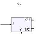
도 2는 도 1a에 도시된 커런트 컨베이어 회로의 심볼을 설명하기 위한 도면이다.
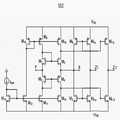
도 3는 도 2에 도시된 커런트 컨베이어 회로의 일례를 설명하기 위한 회로도이다.
도 4는 비교예에 따른 터치 센싱 장치를 개략적으로 설명하기 위한 구성도이다.
도 5a 내지 도 5c는 도 4에 도시된 비교예에 따른 터치 센싱 장치를 통한 터치 센싱 방법을 개략적으로 설명하기 위한 그래프들이다.
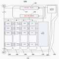
도 6은 본 발명에 따른 터치 센싱 장치를 개략적으로 설명하기 위한 구성도이다.
도 7a 내지 도 7c는 도 6에 도시된 본 발명에 따른 터치 센싱 장치를 통한 터치 센싱 방법을 개략적으로 설명하기 위한 그래프들이다.
도 8a 및 도 8b는 본 발명의 다른 실시예에 따른 터치 센싱 장치를 설명하기 위한 블록도이다.
도 9a는 도 8a에 도시된 커런트 컨베이어 회로의 심볼을 설명하기 위한 도면이고, 도 9b는 도 8a에 도시된 커런트 컨베이어 회로를 설명하기 위한 등가회로도이다.
도 10는 도 8a에 도시된 커런트 컨베이어 회로의 일례를 설명하기 위한 회로도이다.
도 11a 및 도 11b는 본 발명의 또 다른 실시예에 따른 터치 센싱 장치를 설명하기 위한 블록도이다.
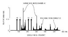
도 12은 터치 센싱 장치가 채용된 휴대폰에서 발생되는 충전기 노이즈를 설명하기 위한 주파수 노이즈 스펙트럼이다.
도 13은 도 12의 주파수 노이즈 스펙트럼에서 구동주파수 설정을 설명하기 위한 주파수 노이즈 스펙트럼이다.1A and 1B are block diagrams for explaining a touch sensing apparatus according to an embodiment of the present invention.
FIG. 2 is a view for explaining symbols of the current conveyor circuit shown in FIG. 1A.
3 is a circuit diagram for explaining an example of the current conveyor circuit shown in Fig.
4 is a schematic diagram for explaining a touch sensing apparatus according to a comparative example.
5A to 5C are graphs for schematically illustrating a touch sensing method using the touch sensing device according to the comparative example shown in FIG.
FIG. 6 is a schematic diagram for explaining a touch sensing apparatus according to the present invention.
FIGS. 7A to 7C are graphs for schematically explaining a touch sensing method using the touch sensing apparatus according to the present invention shown in FIG.
8A and 8B are block diagrams for explaining a touch sensing apparatus according to another embodiment of the present invention.
FIG. 9A is a diagram for explaining the symbols of the current conveyor circuit shown in FIG. 8A, and FIG. 9B is an equivalent circuit diagram for explaining the current conveyor circuit shown in FIG. 8A.
10 is a circuit diagram for explaining an example of the current conveyor circuit shown in Fig. 8A.
11A and 11B are block diagrams for explaining a touch sensing apparatus according to another embodiment of the present invention.
12 is a frequency noise spectrum for explaining charger noise generated in a cellular phone employing the touch sensing device.
13 is a frequency noise spectrum for explaining driving frequency setting in the frequency noise spectrum of FIG.
이하, 첨부한 도면들을 참조하여, 본 발명을 보다 상세하게 설명하고자 한다. 본 발명은 다양한 변경을 가할 수 있고 여러 가지 형태를 가질 수 있는 바, 특정 실시예들을 도면에 예시하고 본문에 상세하게 설명하고자 한다. 그러나, 이는 본 발명을 특정한 개시 형태에 대해 한정하려는 것이 아니며, 본 발명의 사상 및 기술 범위에 포함되는 모든 변경, 균등물 내지 대체물을 포함하는 것으로 이해되어야 한다.DETAILED DESCRIPTION OF THE PREFERRED EMBODIMENTS The present invention will now be described in more detail with reference to the accompanying drawings. The present invention is capable of various modifications and various forms, and specific embodiments are illustrated in the drawings and described in detail in the text. It should be understood, however, that the invention is not intended to be limited to the particular forms disclosed, but includes all modifications, equivalents, and alternatives falling within the spirit and scope of the invention.
각 도면을 설명하면서 유사한 참조부호를 유사한 구성요소에 대해 사용하였다. 첨부된 도면에 있어서, 구조물들의 치수는 본 발명의 명확성을 기하기 위하여 실제보다 확대하여 도시한 것이다.Like reference numerals are used for like elements in describing each drawing. In the accompanying drawings, the dimensions of the structures are enlarged to illustrate the present invention in order to clarify the present invention.
제1, 제2 등의 용어는 다양한 구성요소들을 설명하는데 사용될 수 있지만, 상기 구성요소들은 상기 용어들에 의해 한정되어서는 안 된다. 상기 용어들은 하나의 구성요소를 다른 구성요소로부터 구별하는 목적으로만 사용된다. 예를들어, 본 발명의 권리 범위를 벗어나지 않으면서 제1 구성요소는 제2 구성요소로 명명될 수 있고, 유사하게 제2 구성요소도 제1 구성요소로 명명될 수 있다. 단수의 표현은 문맥상 명백하게 다르게 뜻하지 않는 한, 복수의 표현을 포함한다.The terms first, second, etc. may be used to describe various components, but the components should not be limited by the terms. The terms are used only for the purpose of distinguishing one component from another. For example, without departing from the scope of the present invention, the first component may be referred to as a second component, and similarly, the second component may also be referred to as a first component. The singular expressions include plural expressions unless the context clearly dictates otherwise.
본 출원에서, "포함하다" 또는 "가지다" 등의 용어는 명세서 상에 기재된 특징, 숫자, 단계, 동작, 구성요소, 부분품 또는 이들을 조합한 것이 존재함을 지정하려는 것이지, 하나 또는 그 이상의 다른 특징들이나 숫자, 단계, 동작, 구성요소, 부분품 또는 이들을 조합한 것들의 존재 또는 부가 가능성을 미리 배제하지 않는 것으로 이해되어야 한다.In this application, the terms "comprises", "having", and the like are used to specify that a feature, a number, a step, an operation, an element, a part or a combination thereof is described in the specification, But do not preclude the presence or addition of one or more other features, integers, steps, operations, components, parts, or combinations thereof.
또한, 다르게 정의되지 않는 한, 기술적이거나 과학적인 용어를 포함해서 여기서 사용되는 모든 용어들은 본 발명이 속하는 기술 분야에서 통상의 지식을 가진 자에 의해 일반적으로 이해되는 것과 동일한 의미를 가지고 있다. 일반적으로 사용되는 사전에 정의되어 있는 것과 같은 용어들은 관련 기술의 문맥 상 가지는 의미와 일치하는 의미를 가지는 것으로 해석되어야 하며, 본 출원에서 명백하게 정의하지 않는 한, 이상적이거나 과도하게 형식적인 의미로 해석되지 않는다.Also, unless otherwise defined, all terms used herein, including technical or scientific terms, have the same meaning as commonly understood by one of ordinary skill in the art to which this invention belongs. Terms such as those defined in commonly used dictionaries are to be interpreted as having a meaning consistent with the contextual meaning of the related art and are to be interpreted as either ideal or overly formal in the sense of the present application Do not.
도 1a 및 도 1b는 본 발명의 일실시예에 따른 터치 센싱 장치를 설명하기 위한 블록도이다.1A and 1B are block diagrams for explaining a touch sensing apparatus according to an embodiment of the present invention.
도 1a 및 도 1b를 참조하면, 본 발명의 일실시예에 따른 터치 센싱 장치(100)는 터치 패널(110) 및 터치 센싱 콘트롤러(120)를 포함한다.Referring to FIGS. 1A and 1B, a
상기 터치 패널(110)은 구동신호를 전송하는 복수의 구동전극들(112)과 센싱신호를 전송하는 복수의 센싱전극들(114)을 포함한다. 상기 구동전극들(112)과 상기 센싱전극들(114)은 서로 다른 층에 배치될 수 있다. 도 1에서 구동전극들(112)이 아래층에 배치되고 센싱전극들(114)이 위층에 배치된 것을 도시하였으나 그 역도 가능하다. 상기 구동전극들(112)과 상기 센싱전극들(114)은, 평면상에서 관찰할 때, 매트릭스 타입으로 배치될 수 있다. 한편, 상기 구동전극들(112)과 상기 센싱전극들(114)은 동일한 층에 배치될 수 있다. 예를들어, 상기 구동전극들(112)과 상기 센싱전극들(114)은 서로 교호로 배치될 수도 있다.The
상기 터치 패널(110)은 전형적으로 사용자가 터치 패널(110)을 통해 물체(컴퓨터, 핸드헬드 장치, 휴대폰, 또는 기타 주변 장치의 픽셀화된 디스플레이 등)를 볼 수 있도록 실질적으로 투명하다.The
설명의 편의상, 구동전극들(112)과 센싱전극들(114)이 넓고 잘 보이도록 도시되어 있지만, 실제로는 비교적 좁고 사용자에게 잘 보이지 않게 되어 있을 수 있다. 게다가, 구동전극들(112)과 센싱전극들(114)이 가변 폭 - 예를들어, 전극간 프린지 전계(inter-electrode fringe field)를 증가시키고 그로써 구동전극들(112)과 센싱전극들(114)간 용량성 커플링(electrode-to-electrode capacitive coupling)에 대한 터치의 효과를 증가시키기 위해 매트릭스의 노드의 근방에서 다이어몬드-형상 또는 기타 형상의 패드의 형태로 증가된 폭 - 을 가지도록 설계될 수 있다.For convenience of explanation, although the driving
예시적인 실시 형태에서, 구동전극들(112)과 센싱전극들(114)은 ITO(indium tin oxide) 또는 다른 적당한 전기 전도성 물질로 이루어져 있을 수 있다.In an exemplary embodiment, the driving
상기 터치 센싱 콘트롤러(120)는 구동부(122), 센싱부(124) 및 제어부(126)를 포함한다. 동작시, 상기 터치 센싱 콘트롤러(120)는 상기 구동전극들(112)에 서로 다른 구동주파수를 갖는 복수의 구동신호들을 제공하고, 상기 센싱전극들(114) 각각에서 센싱되는 센싱신호들을 고속 푸리에 변환(FFT)하여 상기 구동주파수에 대한 상기 센싱주파수 크기의 변화량을 근거로 터치 발생 여부를 판별한다.The
상기 구동부(122)는 서로 다른 구동주파수를 갖는 구동신호들을 상기 구동전극들(112) 각각에 동시에 제공한다. 예를들어, 제1 구동전극에는 제1 주파수(f0)를 갖는 구동신호를 제공하고, 제2 구동전극에는 제2 주파수(f1)를 갖는 구동신호를 제공하고, 제3 구동전극에는 제3 주파수(f2)를 갖는 구동신호를 제공하고, 제4 구동전극에는 제4 주파수(f3)를 갖는 구동신호를 제공한다. 상기한 서로 다른 구동주파수를 갖는 구동신호들은 상기 제어부(126)의 제어에 따라 생성될 수 있다. 본 실시예에서, 상기 구동신호들은 사인(sine)파 또는 코사인(cosine)파 등의 정현파를 포함할 수 있다. 본 실시예에서, 구동신호들은 서로 다른 위상에서 시작할 수 있다. 본 실시예에서, 상기 구동부(122)는 서로 다른 구동주파수를 갖는 구동신호들을 이용하여 동시에 상기 구동전극들(112)을 구동하므로 터치 센싱 시간이 빠르고 이에 따라 고속 응답이 가능하다.The driving
본 실시예에서, 상기 구동부(122)는 상기 구동전극들 각각에 정현파를 제공하는 디지털 함수 발생부를 포함할 수 있다. 상기 디지털 함수 발생부는 상기 구동전극들 각각에 연결되어 상기 터치 구동 제어부의 제어에 응답하여 사인파를 정확한 주파수, 주기 및 위상을 정밀하게 발생시키도록 구성된 복수의 직접 디지털 합성(Direct Digital Synthesis, 이하, DDS) 모듈들을 포함할 수 있다.In the present embodiment, the driving
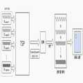
상기 센싱부(124)는 차동 수신부(410), 제1 신호 증폭부(420), 액티브 필터부(430), 제2 신호 증폭부(440), 아날로그-디지털 변환부(450), 고속 푸리에 변환부(460) 및 터치 판별부(470)를 포함한다.The
상기 센싱부(124)는 상기 센싱전극들(114) 각각에서 센싱신호를 차동적으로 수신하여 차동 센싱신호를 생성하고, 상기 차동 센싱신호를 고속 푸리에 변환하여 차동 센싱신호의 주파수 크기를 획득하고, 상기 센싱신호의 주파수 크기와 상기 구동신호의 주파수 크기간의 변화량을 근거로 터치 발생 여부를 판별한다.The
즉, 터치가 발생한 전극은 해당 전극에 부여된 정현파의 진폭이 감소된 형태로 수신이 된다. 감쇄된 정현파의 주파수는 상기 차동 수신부(410)를 통해 감소된 양만 감지되고 증폭됨으로 터치로 발생한 신호 변화량에 의해 터치가 발생한 센서의 구동주파수에 해당하는 FFT 결과의 진폭(Magnitude)값은 증가한다.That is, the electrode where the touch occurs is received in a form in which the amplitude of the sinusoidal wave given to the electrode is reduced. Since the frequency of the attenuated sinusoidal wave is detected and amplified by the
상기 차동 수신부(410)는 상기 센싱전극들(114) 각각에 연결되어 서로 인접하는 센싱전극들의 센싱신호들을 수신한다. 상기 차동 수신부(410)는 복수의 커런트 컨베이어 회로들(current conveyor circuit)을 포함할 수 있다. 상기 커런트 컨베이어 회로들 각각은 상기 센싱신호들을 차동적으로 수신하여 상기 차동 센싱신호를 생성하고 생성된 차동 센싱신호를 상기 신호 증폭부(430)에 제공한다. 본 실시예에서, 상기 커런트 컨베이어 회로는 차동 커런트 컨베이어(differential current conveyor) 회로일 수 있다.The
상기 제1 신호 증폭부(420)는 복수의 제1 신호 증폭기들을 포함하고, 상기 차동 수신부(410)에서 출력되는 차동 센싱신호를 증폭하여 상기 액티브 필터부(430)에 제공한다. 본 실시예에서, 상기 제1 신호 증폭기들은 차동증폭기(differential amplifier)를 포함할 수 있다.The first
상기 액티브 필터부(430)는 증폭된 센싱신호들 각각을 액티브 필터링하여 상기 아날로그-디지털 변환부(450)에 제공한다. 상기 액티브 필터부(430)는 복수의 밴드 패스 필터들(band pass filters)을 포함할 수도 있다. 한편, 상기 액티브 필터부(430)는 복수의 로우 패스 필터들(low pass filters)을 포함할 수도 있다.The
즉, 수신단은 입력신호의 주파수 대역을 관심을 갖고 있는 구동 주파수 대역으로 설정할 수 있도록 밴드 패스 필터를 사용할 수도 있다. 또는, 고속 푸리에 변환(FFT)의 분해능에 따라 저주파 성분은 FFT로 구별해 낼 수 있음으로 로우 패스 필터들을 사용할 수도 있다. 또는, 커런트 컨베이어와 전압 증폭기의 고주파 차단 주파수 성분을 이용하여 로우 패스 필터 없이 바로 증폭기 단을 연결 할 수도 있다.That is, the receiving end may use a band pass filter to set the frequency band of the input signal to a driving frequency band of interest. Alternatively, low-pass filters may be used because low-frequency components can be distinguished by FFT according to the resolution of fast Fourier transform (FFT). Alternatively, the amplifier stage may be directly connected without a low-pass filter using the current conveyor and the high frequency cut-off frequency component of the voltage amplifier.
상기 제2 신호 증폭부(440)는 복수의 제2 신호 증폭기들을 포함하고, 상기 액티브 필터링된 센싱신호들을 증폭하여 상기 아날로그-디지털 변환부(450)에 제공한다. 본 실시예에서, 상기 제2 신호 증폭기들은 차동증폭기(differential amplifier)를 포함할 수 있다.The second
상기 아날로그-디지털 변환부(450)는 복수의 아날로그-디지털 변환기들을 포함하고, 액티브 필터링된 센싱신호들 각각을 디지털 변환하여 상기 고속 푸리에 변환부(460)에 제공한다. 상기 아날로그-디지털 변환부(450)는 상기 구동주파수보다 최소 2배 이상 빠른 주파수로 ADC변환을 실시한다. 상기 구동주파수에 대한 정보는 상기 제어부(126)로부터 제공받을 수 있다. 본 실시예에서, 상기 아날로그-디지털 변환기는 차동 아날로그-디지털 변환기(differential ADC)를 포함할 수 있다.The analog-to-
상기 고속 푸리에 변환부(460)는 복수의 고속 푸리에 변환기들을 포함하고, 디지털 변환된 센싱신호들 각각을 고속 푸리에 변환하여 센싱신호들 각각을 시간 도메인(Time Domain)에서 주파수 도메인(Frequency Domain)으로 변환하여 주파수 성분과 주파수 성분의 크기를 획득한 후 상기 터치 판별부(470)에 제공한다. 본 실시예에서, 시간 도메인(time domain)에서의 센싱을 주파수 도메인에서 센싱으로 변환함으로써, 디지털 신호처리에 매우 유용하다.The fast
상기 터치 판별부(470)는 상기 구동신호의 주파수 크기를 기준으로 고속 푸리에 변환된 센싱신호의 주파수 크기간의 변화량을 근거로 터치 발생 여부를 판별한다. 상기 구동신호의 주파수에 대한 정보는 상기 제어부(126)로부터 제공받을 수 있다.The
상기 제어부(126)는 터치 구동 제어부(127) 및 터치 센싱 제어부(128)를 포함한다.The
상기 터치 구동 제어부(127)는 서로 다른 구동주파수를 갖는 구동신호들을 상기 구동전극들(112) 각각에 동시에 제공하도록 상기 구동부(122)의 동작을 제어한다.The touch
상기 터치 센싱 제어부(128)는 상기 아날로그-디지털 변환부(450)가 상기 구동신호의 주파수 보다 빠른 주파수로 아날로그-디지털 변환하도록 상기 구동신호의 주파수에 대한 정보를 상기 아날로그-디지털 변환부(450)에 제공한다.The
상기 터치 센싱 콘트롤러(120)는 측정된 크기 및 연관된 파라미터를 저장하는 하나 이상의 메모리 장치(미도시)와, 필요한 계산 및 제어 기능을 수행하는 마이크로프로세서(미도시)를 더 포함할 수 있다.The
상기 터치 센싱 콘트롤러(120) 및/또는 상기 터치 센싱 장치(100)의 기타 부분은, 본 명세서에 기술된 기능들 중 하나 이상의 기능을 수행하기 위해, 하나 이상의 ASIC(application-specific integrated circuit), ASSP(application-specific standard product) 등으로 구현될 수 있다.The
이상에서 설명된 바와 같이, 터치스크린 구동 및 감지를 위해 주파수 도메인에서 정현파(Sine wave)를 갖는 서로 다른 송신 주파수를 갖는 구동신호들을 터치패널의 구동전극에 동시에 전송하고, 센싱전극으로부터 수신된 신호간의 차동(differential) 성분, 즉 터치 변화량만을 추출하여 증폭한 후에 FFT(Fast Fourier Transform)를 수행하여 그 변화량을 터치 감도로 판단한다.As described above, driving signals having different sine waves in the frequency domain having different sine waves for driving and sensing the touch screen are simultaneously transmitted to the driving electrodes of the touch panel, and signals between the signals received from the sensing electrodes After extracting and amplifying only a differential component, that is, a touch change amount, FFT (Fast Fourier Transform) is performed to judge the amount of change as touch sensitivity.
또한, 상기한 방법과 노이즈 스펙트럼 분석을 통해 송신주파수를 실시간 변경하여 사용함으로써, 터치 구동 및 감지속도와 터치 감도를 향상시킬 수 있고, 노이즈에 대한 내성 또한 향상시킬 수 있다.Further, by changing the transmission frequency in real time by using the above method and noise spectrum analysis, it is possible to improve the touch driving, the sensing speed and the touch sensitivity, and also improve the immunity against noise.
또한, 본 발명에 따르면, 센싱전극들 각각의 종단에 차동 수신부를 배치하여 이미 알고 있는 송신 주파수 성분의 이득의 변화량을 통해 터치를 감지하므로써 다음과 같은 장점이 있다.In addition, according to the present invention, a differential receiver is disposed at the end of each of the sensing electrodes to detect a touch through a variation amount of a gain of a known transmission frequency component.
주파수 성분을 갖고 있는 노이즈 성분과 터치 성분의 구분이 용이하다. 따라서, 터치 스크린의 동작 환경에서 발생하는 노이즈 성분에 대해 별도의 프로세싱 없이 FFT의 결과를 사용하여 원하는 주파수의 수신 신호의 변화량만을 측정할 수 있으므로 노이즈에 대한 해결이 용이하다.It is easy to distinguish a noise component having a frequency component from a touch component. Therefore, it is easy to solve the noise because the noise component generated in the operating environment of the touch screen can be measured by using the result of FFT without any additional processing and only the variation of the received signal of the desired frequency can be measured.
동시에 복수의 구동전극을 구동함으로 터치 센싱 시간이 빨라 고속 응답이 용이하다.By driving a plurality of driving electrodes at the same time, the touch sensing time is fast and a high-speed response is easy.
시간 도메인(time domain)에서의 센싱을 주파수 도메인에서 센싱하므로써 디지털 신호 처리에 매우 유용하다.It is very useful for digital signal processing by sensing the time domain sensing in the frequency domain.
센서의 구동 주파수를 센서의 시상수에 근접하게 또는 감쇄를 감안하고 보다 빠르게 구동이 가능함으로 고저항성 센서(예를들어, 중대형 크기의 터치 패널 또는 단면센서)의 구동에 매우 유리하다.It is very advantageous for driving a high-resistance sensor (for example, a middle-size or large-sized touch panel or a cross-sectional sensor) because the driving frequency of the sensor is close to the time constant of the sensor or can be driven more quickly in consideration of attenuation.
도 2는 도 1a에 도시된 커런트 컨베이어 회로(412)의 심볼을 설명하기 위한 도면이다. 도 3는 도 2에 도시된 커런트 컨베이어 회로(412)의 일례를 설명하기 위한 회로도이다.Fig. 2 is a diagram for explaining the symbols of the
도 2 및 도 3을 참조하면, 커런트 컨베이어 회로(412)는 전압 및 전류 팔로워(follower)들을 상호 연결함으로써 얻어진 다섯 단자를 갖는 디바이스이다.Referring to Figures 2 and 3, the
상기 커런트 컨베이어 회로의 다섯 단자들은, 전압 입력 단자(Y), 제1 전류 입력 단자(X1), 제2 전류 입력 단자(X2), 제1 전류 출력 단자(Z1) 및 제2 전류 출력 단자(Z2)를 포함한다.The five terminals of the current conveyor circuit include a voltage input terminal Y, a first current input terminal X1, a second current input terminal X2, a first current output terminal Z1 and a second current output terminal Z2 ).
상기 커런트 컨베이어 회로의 2극성 전류 출력의 구현은 잡음 감소에 기여하며, 의사 차동(quasi-differential) 채널 구축을 위해 사용될 수 있다.The implementation of the bipolar current output of the current conveyor circuit contributes to noise reduction and can be used for quasi-differential channel construction.
상기 제1 전류 출력 단자(Z1)는 전류 출력에 적합한 하이 임피던스 출력 단자이다. 상기 제1 출력 전류(IZ1)의 방향은 제1 전류 입력 단자(X1)에서의 입력 전류에 비례한다. 상기 커런트 컨베이어 회로의 입-출력 관계는 하기 행렬 등식에 의해 설명될 수 있다.The first current output terminal Z1 is a high impedance output terminal suitable for current output. The direction of the first output current IZ1 is proportional to the input current at the first current input terminal X1. The input-output relationship of the current conveyor circuit can be described by the following matrix equation.
[식 1] [Formula 1]

상기한 커패시턴스 센싱 회로의 복수 노드들에서 커패시턴스를 센싱하기 위해 커런트 컨베이어 회로를 사용하는 것은 다음 이득을 제공할 수 있다.Using a current conveyor circuit to sense capacitance at multiple nodes of the capacitance sensing circuit described above can provide the following benefits.
첫째, 커런트 컨베이어 회로는 로우 임피던스 전류 입력(XI)를 가지며, 이는 RF 또는 ESD와 같은 하이 임피던스 잡음 신호들에 대한 좋은 면역을 제공할 수 있다.First, the current conveyor circuit has a low impedance current input (XI), which can provide good immunity to high impedance noise signals such as RF or ESD.
둘째, 전류 입력(XI)의 전압 전위는 하이 임피던스 전압 입력(YV)에 의해 제어되며, 이는 복수의 커패시턴스 센싱 모드들(셀프 커패시턴스 센싱 모드 및 상호 커패시턴스 센싱 모드)을 위한 최적의 구조를 구현하는 것을 허용한다.Second, the voltage potential of the current input XI is controlled by the high impedance voltage input YV, which allows for implementing an optimal structure for a plurality of capacitance sensing modes (self-capacitance sensing mode and mutual capacitance sensing mode) Allow.
셋째, 커런트 컨베이어 회로의 전류 출력들은 시그마-델타 변조기 또는 간단한 전하 적분 회로들과 같은 전하 적분/균형 회로들을 사용함으로써 측정 가능한 형태로 쉽게 변환될 수 있다.Third, the current outputs of the current conveyor circuit can be easily converted into a measurable form by using charge integrator / balance circuits such as a sigma-delta modulator or simple charge integrator circuits.
마지막으로, 커런트 컨베이어 회로는 외부 폐쇄 루프 없이 동작할 수 있으며, 이는 서로 다른 센서 기생 커패시턴스에서 안정성을 제공한다. 커런트 컨베이어 회로들은 신호 증폭, 필터링 및 정류 아날로그 신호의 곱셈 및 나눗셈, 트랜스 임피던스 및 트랜스 컨덕턴스 증폭기, 및 광대역 라인 드라이버의 구축을 위해 아날로그 및 혼합 신호 ASIC 내에서 광범위하게 사용된다. 때로는 이상적인 트랜지스터라 불리는, 커런트 컨베이어 회로의 소수의 개별 구현만이 존재한다.Finally, the current conveyor circuit can operate without an external closed loop, which provides stability in different sensor parasitic capacitances. Current conveyor circuits are widely used in analog and mixed signal ASICs for signal amplification, filtering and rectification, multiplication and division of analog signals, transimpedance and transconductance amplifiers, and the construction of broadband line drivers. There are only a few individual implementations of current conveyor circuits, sometimes called ideal transistors.
일 실시예에서, 커런트 컨베이어 회로는 폐쇄 루프 시스템을 사용하는, 연산 증폭기 기반 아키텍쳐일 수 있다. 다른 실시예에서, 커런트 컨베이어 회로는, 개방 루프 아키텍쳐를 사용하는 트랜스리니어 원리(translinear principle)를 사용할 수 있다. 대안적으로, 본 개시의 이득을 갖는 본 기술분야의 통상적인 기술자에 의해 인식될 것과 같이, 커패시턴스를 센싱하기 위해 커런트 컨베이어 회로의 다른 구현들이 사용될 수 있다.In one embodiment, the current conveyor circuit may be an operational amplifier based architecture using a closed loop system. In another embodiment, the current conveyor circuit may use a translinear principle using an open-loop architecture. Alternatively, other implementations of the current conveyor circuit may be used to sense the capacitance, as will be appreciated by those of ordinary skill in the art having the benefit of this disclosure.
본 실시예에서, 커런트 컨베이어 회로들은 첫번째 커런트 컨베이어 회로, 마지막번째 커런트 컨베이어 회로 및 나머지 커런트 컨베이어 회로들은 서로 다른 비대칭적 구조를 갖는다.In this embodiment, the current conveyor circuits have different asymmetric structures in the first current conveyor circuit, the last current conveyor circuit, and the remaining current conveyor circuits.
MOSFET들 각각의 길이는 동일하다 가정할 때 각 MOSFET들 각각의 폭은 아래와 같은 관계가 있다.Assuming that the lengths of each of the MOSFETs are the same, the widths of the respective MOSFETs are as follows.
첫번째 센싱전극에 연결된 커런트 컨베이어 회로의 경우, M11: M13=2:1의 관계와 M12:M14=2:1의 관계에 있다. 마지막번째 센싱전극에 연결된 커런트 컨베이어 회로의 경우, M11: M13=1:2의 관계와 M12:M14=1:2의 관계에 있다. 나머지 센싱전극들 각각에 연결된 커런트 컨베이어 회로의 경우, M11: M13=1:1의 관계와 M12:M14=1:1의 관계에 있다.In the case of the current conveyor circuit connected to the first sensing electrode, the relationship of M11: M13 = 2: 1 and M12: M14 = 2: 1 are satisfied. In the case of the current conveyor circuit connected to the last sensing electrode, there is a relation of M11: M13 = 1: 2 and M12: M14 = 1: 2. In the case of the current conveyor circuit connected to each of the remaining sensing electrodes, the relationship of M11: M13 = 1: 1 and M12: M14 = 1: 1 are satisfied.
그러면, 이하에서 본 발명에 따른 터치 센싱 장치를 이용한 터치 센싱 방법과 비교예에 따른 터치 센싱 장치를 이용한 터치 센싱 방법을 비교 설명한다.Hereinafter, the touch sensing method using the touch sensing device according to the present invention and the touch sensing method using the touch sensing device according to the comparative example will be compared.
도 4는 비교예에 따른 터치 센싱 장치를 개략적으로 설명하기 위한 구성도이다. 도 5a 내지 도 5c는 도 4에 도시된 비교예에 따른 터치 센싱 장치를 통한 터치 센싱 방법을 개략적으로 설명하기 위한 그래프들이다.4 is a schematic diagram for explaining a touch sensing apparatus according to a comparative example. 5A to 5C are graphs for schematically illustrating a touch sensing method using the touch sensing device according to the comparative example shown in FIG.
도 4 내지 도 5c를 참조하면, 서로 다른 구동주파수를 갖는 구동신호들이 터치 패널에 순차적으로 제공된다. 상기 터치 패널은 정전용량 방식으로 사용자의 터치 여부를 판단하기 위해 구비된다.4 to 5C, driving signals having different driving frequencies are sequentially provided to the touch panel. The touch panel is provided to judge whether or not the user touches the touch panel in a capacitive method.
터치 패널에서 센싱된 센싱신호들은 미분된 신호 형태를 갖는다.Sensing signals sensed on the touch panel have a differentiated signal form.
미분된 신호 형태의 센싱신호들은 증폭된 후 적분된다.The sensing signals in the form of a differentiated signal are amplified and then integrated.
적분된 센싱신호들을 통해 어느 위치에서 터치가 발생되었는지 좌표가 도출된다.Through the integrated sensing signals, coordinates are derived from which position the touch occurred.
이처럼, 비교예에 따른 터치 센싱 장치의 구동 및 감지 기술은 시간도메인에서 구동전극에 일정 주기를 갖는 구형파(또는 사각파)를 순차적으로 송신하고 센싱전극를 통해 수신된 센싱신호인 구형파의 미분신호를 누적/적분하여 신호 크기의 변화량으로부터 사용자의 터치 여부를 판단하였다. 띠라서, 고감도 센싱이 어렵고 대형화에 단점이 있을 뿐만 아니라 노이즈 성분에 대한 취약하다.As described above, the driving and sensing technology of the touch sensing device according to the comparative example sequentially transmits square waves (or square waves) having a predetermined period to the driving electrodes in the time domain, and accumulates the differential signals of the square waves, which are sensing signals received through the sensing electrodes, / Integrated to judge whether the user is touched or not based on the amount of change in the signal size. It is difficult to sense high sensitivity, and it is not only disadvantageous in size, but also vulnerable to noise components.
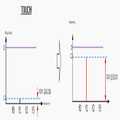
도 6은 본 발명에 따른 터치 센싱 장치를 개략적으로 설명하기 위한 구성도이다. 도 7a 내지 도 7c는 도 6에 도시된 본 발명에 따른 터치 센싱 장치를 통한 터치 센싱 방법을 개략적으로 설명하기 위한 그래프들이다.FIG. 6 is a schematic diagram for explaining a touch sensing apparatus according to the present invention. FIGS. 7A to 7C are graphs for schematically explaining a touch sensing method using the touch sensing apparatus according to the present invention shown in FIG.
도 6 내지 도 7c를 참조하면, 서로 다른 구동주파수를 갖는 구동신호들이 터치 패널에 동시에 제공된다. 상기 터치 패널은 정전용량 방식으로 사용자의 터치 여부를 판단하기 위해 구비된다.6 to 7C, driving signals having different driving frequencies are simultaneously provided to the touch panel. The touch panel is provided to judge whether or not the user touches the touch panel in a capacitive method.
터치 패널에서 센싱된 센싱신호들은 합성된 신호 형태를 갖는다.The sensing signals sensed on the touch panel have a synthesized signal form.
합성된 신호 형태의 센싱신호들은 증폭된 후 FFT 처리된다.The synthesized signal is amplified and FFT - processed.
FFT 처리된 센싱신호들은 분해 및 해석되어 어느 위치에서 터치가 발생되었는지 좌표가 도출된다.The FFT-processed sensing signals are decomposed and interpreted to determine coordinates at which position the touch occurred.
이처럼, 본 발명에 따른 터치 센싱 장치의 구동 및 감지 기술은 터치 스크린의 구동 및 감지를 위해 통신 이론을 응용하여 신호의 처리를 주파수 도메인으로 전환하였다. 또한, 터치 감도 향상을 차동(differential) 신호 처리 기법을 적용하여 터치스크린 신호를 처리하였다.As described above, the driving and sensing technology of the touch sensing apparatus according to the present invention converts the signal processing into the frequency domain by applying the communication theory for driving and sensing the touch screen. In addition, the touch screen signal was processed by applying a differential signal processing technique to enhance the touch sensitivity.
구체적으로, 전통적인 통신 기법인 AM통신 방법의 원리를 응용하여 서로 다른 주파수를 갖는 다수의 정현파(사인파) 구동신호들 각각을 신호 전달 매질인 구동전극에 동시에 제공한다. 이어, 센싱전극으로부터 수신된 여러 주파수가 섞인 센싱신호에 대해서 각 수신단 간의 차동(differential) 성분, 즉 터치 변화량만을 추출한다. 이어, 터치로 발생된 터치 변위량 만을 증폭한 후에 FFT를 수행하여 송신한 주파수들을 찾아내고, 사용자의 터치로부터 발생한 각 주파수별 진폭(Amplitude, Magnitude)의 변화량을 측정함으로써, 사용자의 터치 여부 및 터치스크린 상의 절대 좌표를 계산할 수 있다. 따라서, 노이즈 스펙트럼 분석을 통해 송신 주파수를 실시간 변경하여 사용함으로써, 터치 구동 속도, 감지 속도 및 터치 감도를 향상시킬 수 있다. 또한 노이즈 성분이 주파수를 회피하거나 노이즈로 인한 센싱신호의 영향을 최소화할 수 있어 터치 스크린에서의 터치 감도를 향상시킬 수 있다.Specifically, by applying the principle of the AM communication method, which is a conventional communication technique, a plurality of sinusoidal (sinusoidal) driving signals having different frequencies are simultaneously provided to the driving electrodes, which are signal transmission media. Then, only the differential component between the receiving ends, that is, the amount of touch change, is extracted for the sensing signals mixed with the frequencies received from the sensing electrodes. Then, only the amount of the touch displacement generated by the touch is amplified, and then the FFT is performed to find the transmitted frequency. By measuring the amount of change of the amplitude (Magnitude) of each frequency generated from the touch of the user, Can be calculated. Therefore, by changing the transmission frequency in real time by using the noise spectrum analysis, it is possible to improve the touch driving speed, sensing speed and touch sensitivity. In addition, the noise component can avoid the frequency or minimize the influence of the sensing signal due to the noise, thereby improving the touch sensitivity on the touch screen.
도 8a 및 도 8b는 본 발명의 다른 실시예에 따른 터치 센싱 장치를 설명하기 위한 블록도이다.8A and 8B are block diagrams for explaining a touch sensing apparatus according to another embodiment of the present invention.
도 8a 및 도 8b를 참조하면, 본 발명의 다른 실시예에 따른 터치 센싱 장치(200)는 터치 패널(110) 및 터치 센싱 콘트롤러(220)를 포함한다.8A and 8B, the
상기 터치 패널(110)은 도 1a에 도시된 터치 패널(110)과 동일하므로 동일한 도면부호를 부여하고 상세한 설명은 생략한다.Since the
상기 터치 센싱 콘트롤러(220)는 구동부(122), 센싱부(224) 및 제어부(126)를 포함한다. 동작시, 상기 터치 센싱 콘트롤러(220)는 상기 구동전극들(112)에 서로 다른 구동주파수를 갖는 복수의 구동신호들을 제공하고, 상기 센싱전극들(114) 각각에서 센싱되는 센싱신호들을 고속 푸리에 변환(FFT)하여 상기 구동주파수에 대한 상기 센싱주파수 크기의 변화량을 근거로 터치 발생 여부를 판별한다.The
상기 구동부(122)는 도 1a에 도시된 구동부(122)와 동일하므로 동일한 도면부호를 부여하고 상세한 설명은 생략한다.The driving
상기 센싱부(224)는 상기 센싱전극들(114) 각각에서 센싱신호를 차동적으로 수신하여 차동 센싱신호를 생성하고, 상기 차동 센싱신호를 고속 푸리에 변환하여 차동 센싱신호의 주파수 크기를 획득하고, 상기 센싱신호의 주파수 크기와 상기 구동신호의 주파수 크기간의 변화량을 근거로 터치 발생 여부를 판별한다.The
상기 센싱부(224)는 차동 수신부(510), 제1 신호 증폭부(520), 액티브 필터부(430), 제2 신호 증폭부(440), 아날로그-디지털 변환부(450), 고속 푸리에 변환부(460) 및 터치 판별부(470)를 포함한다.The
상기 차동 수신부(510)는 상기 센싱전극들(114) 각각에 연결되어 서로 인접하는 센싱전극들의 센싱신호들을 수신한다. 상기 차동 수신부(510)는 복수의 커런트 컨베이어 회로들을 포함할 수 있다. 상기 커런트 컨베이어 회로들 각각은 상기 센싱신호들을 수신하여 상기 차동 센싱신호를 생성하고 생성된 차동 센싱신호를 상기 제1 신호 증폭부(520)에 제공한다. 본 실시예에서, 상기 커런트 컨베이어 회로는 싱글 엔디드 듀얼 아웃풋 커런트 컨베이어(single ended dual current conveyor) 회로일 수 있다.The
상기 커런트 컨베이어 회로의 수는 상기 센싱전극의 수와 동일하다. 이에 따라, 홀수번째 커런트 컨베이어 회로는 홀수번째 센싱전극에 연결되고, 짝수번째 커런트 컨베이어 회로는 짝수번째 센싱전극에 연결된다. 또한 첫번째 센싱전극에 연결된 커런트 컨베이어 회로는 플로팅된 제1 출력단 및 첫번째 신호 증폭기에 연결된 제2 출력단을 포함하고, 마지막번째 센싱전극에 연결된 커런트 컨베이어 회로는 마지막번째 신호 증폭기에 연결된 제1 출력단 및 플로팅된 제2 출력단을 포함할 수 있다.The number of the current conveyor circuits is equal to the number of the sensing electrodes. Accordingly, the odd-number current conveyor circuit is connected to the odd-numbered sensing electrode, and the even-numbered current conveyor circuit is connected to the even-numbered sensing electrode. The current conveyor circuit connected to the first sensing electrode includes a first output terminal that is floated and a second output terminal that is connected to the first signal amplifier. The current conveyor circuit connected to the last sensing electrode includes a first output terminal connected to the last signal amplifier, And a second output stage.
상기 제1 신호 증폭부(520)는 복수의 제1 신호 증폭기들을 포함하고, 상기 차동 수신부(510)에서 출력되는 차동 센싱신호를 증폭하여 상기 액티브 필터부(430)에 제공한다. 본 실시예에서, 상기 제1 신호 증폭기들은 차동증폭기(differential amplifier)를 포함할 수 있다.The first
상기 액티브 필터부(430)는 증폭된 센싱신호들 각각을 액티브 필터링하여 상기 아날로그-디지털 변환부(450)에 제공한다. 상기 액티브 필터부(430)는 복수의 밴드 패스 필터들(band pass filters)을 포함할 수도 있다. 한편, 상기 액티브 필터부(430)는 복수의 로우 패스 필터들(low pass filters)을 포함할 수도 있다.The
상기 제2 신호 증폭부(440)는 복수의 제2 신호 증폭기들을 포함하고, 상기 액티브 필터링된 센싱신호들을 증폭하여 상기 아날로그-디지털 변환부(450)에 제공한다. 본 실시예에서, 상기 제2 신호 증폭기들은 차동증폭기(differential amplifier)를 포함할 수 있다.The second
상기 아날로그-디지털 변환부(450)는 복수의 아날로그-디지털 변환기들을 포함하고, 액티브 필터링된 센싱신호들 각각을 디지털 변환하여 상기 고속 푸리에 변환부(460)에 제공한다. 상기 아날로그-디지털 변환부(450)는 상기 구동주파수보다 최소 2배 이상 빠른 주파수로 ADC변환을 실시한다. 상기 구동주파수에 대한 정보는 상기 제어부(126)로부터 제공받을 수 있다. 본 실시예에서, 상기 아날로그-디지털 변환기는 차동 아날로그-디지털 변환기(differential ADC)를 포함할 수 있다.The analog-to-
상기 고속 푸리에 변환부(460)는 복수의 고속 푸리에 변환기들을 포함하고, 디지털 변환된 센싱신호들 각각을 고속 푸리에 변환하여 센싱신호들 각각을 시간 도메인(Time Domain)에서 주파수 도메인(Frequency Domain)으로 변환하여 주파수 성분과 주파수 성분의 크기를 획득한 후 상기 터치 판별부(470)에 제공한다. 본 실시예에서, 시간 도메인(time domain)에서의 센싱을 주파수 도메인에서 센싱으로 변환함으로써, 디지털 신호처리에 매우 유용하다.The fast
상기 터치 판별부(470)는 상기 구동신호의 주파수 크기를 기준으로 고속 푸리에 변환된 센싱신호의 주파수 크기간의 변화량을 근거로 터치 발생 여부를 판별한다. 상기 구동신호의 주파수에 대한 정보는 상기 제어부(126)로부터 제공받을 수 있다.The
상기 제어부(126)는 터치 구동 제어부(127) 및 터치 센싱 제어부(128)를 포함한다.The
상기 터치 구동 제어부(127)는 서로 다른 구동주파수를 갖는 구동신호들을 상기 구동전극들(112) 각각에 동시에 제공하도록 상기 구동부(122)의 동작을 제어한다.The touch
상기 터치 센싱 제어부(128)는 상기 아날로그-디지털 변환부(450)가 상기 구동신호의 주파수 보다 빠른 주파수로 아날로그-디지털 변환하도록 상기 구동신호의 주파수에 대한 정보를 상기 아날로그-디지털 변환부(450)에 제공한다.The
상기 터치 센싱 콘트롤러(220)는 측정된 크기 및 연관된 파라미터를 저장하는 하나 이상의 메모리 장치(미도시)와, 필요한 계산 및 제어 기능을 수행하는 마이크로프로세서(미도시)를 더 포함할 수 있다.The
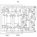
도 9a는 도 8a에 도시된 커런트 컨베이어 회로의 심볼을 설명하기 위한 도면이고, 도 9b는 도 8a에 도시된 커런트 컨베이어 회로를 설명하기 위한 등가회로도이다. 도 10은 도 8a에 도시된 커런트 컨베이어 회로의 일례를 설명하기 위한 회로도이다.FIG. 9A is a diagram for explaining the symbols of the current conveyor circuit shown in FIG. 8A, and FIG. 9B is an equivalent circuit diagram for explaining the current conveyor circuit shown in FIG. 8A. Fig. 10 is a circuit diagram for explaining an example of the current conveyor circuit shown in Fig. 8A.
도 9a 내지 도 10을 참조하면, 커런트 컨베이어 회로는 전압 및 전류 팔로워(follower)들을 상호 연결함으로써 얻어진, 네 개의 단자를 갖는 디바이스이다.Referring to Figures 9A-10, the current conveyor circuit is a device with four terminals, obtained by interconnecting voltage and current followers.
상기 커런트 컨베이어 회로의 네 단자들은, 전압 입력 단자(YV), 전류 입력 단자(XI), 전류 출력 단자(IZ+) 및 전류 출력 단자(IZ-)를 포함한다. 상기 전압 입력 단자(YV)는 하이 임피던스 단자인데 반해, 상기 전류 입력 단자(XI)는 로우 임피던스 단자이다. 상기 전압 입력 단자(YV)에 가해진 입력 전압(VY)은 상기 전류 입력 단자(XI)의 전압(VX)로 전달될 수 있다(즉, VX = VY). 추가적으로, 상기 전압 입력 단자(YV)는 하이 임피던스 입력이므로, 상기 전압 입력 단자(YV)로 전류가 흐르지 않는다.Four terminals of the current conveyor circuit include a voltage input terminal YV, a current input terminal XI, a current output terminal IZ +, and a current output terminal IZ-. The voltage input terminal YV is a high impedance terminal, while the current input terminal XI is a low impedance terminal. The input voltage VY applied to the voltage input terminal YV may be transferred to the voltage VX of the current input terminal XI (i.e., VX = VY). In addition, since the voltage input terminal YV is a high impedance input, no current flows to the voltage input terminal YV.
상기 전류 입력 단자(XI)에 가해진 입력 전류(I0)는 출력 단자들(IZ+ 및 IZ-)에서 출력 전류(IZ+)로 전달된다. 상기 출력 단자들(IZ+ 및 IZ-)는 균형잡힌 전류 출력(즉, IZ+ = -IX, IZ- = +IX)을 위해 사용된다.The input current I0 applied to the current input terminal XI is transferred from the output terminals IZ + and IZ- to the output current IZ +. The output terminals IZ + and IZ- are used for a balanced current output (i.e., IZ + = -IX, IZ- = + IX).
상기 커런트 컨베이어 회로의 2극성 전류 출력의 구현은 잡음 감소에 기여하며, 의사 차동(quasi-differential) 채널 구축을 위해 사용될 수 있다.The implementation of the bipolar current output of the current conveyor circuit contributes to noise reduction and can be used for quasi-differential channel construction.
상기 출력 단자(IZ+)는 전류 출력에 적합한 하이 임피던스 출력 단자이다. 상기 출력 전류(IZ)의 방향은 전류 입력 단자(XI)에서의 입력 전류에 비례한다. 상기 커런트 컨베이어 회로의 입-출력 관계는 하기 행렬 등식에 의해 설명될 수 있다.The output terminal IZ + is a high impedance output terminal suitable for the current output. The direction of the output current IZ is proportional to the input current at the current input terminal XI. The input-output relationship of the current conveyor circuit can be described by the following matrix equation.
[식 2] [Formula 2]

커패시턴스 센싱 회로의 복수의 노드들에서 커패시턴스를 센싱하기 위해 커런트 컨베이어 회로를 사용하는 것은 다음 이득을 제공할 수 있다.Using a current conveyor circuit to sense capacitance at a plurality of nodes of the capacitance sensing circuit may provide the following benefits.
첫째, 커런트 컨베이어 회로는 로우 임피던스 전류 입력(XI)를 가지며, 이는 RF 또는 ESD와 같은 하이 임피던스 잡음 신호들에 대한 좋은 면역을 제공할 수 있다.First, the current conveyor circuit has a low impedance current input (XI), which can provide good immunity to high impedance noise signals such as RF or ESD.
둘째, 전류 입력(XI)의 전압 전위는 하이 임피던스 전압 입력(YV)에 의해 제어되며, 이는 복수의 커패시턴스 센싱 모드들(셀프 커패시턴스 센싱 모드 및 상호 커패시턴스 센싱 모드)을 위한 최적의 구조를 구현하는 것을 허용한다.Second, the voltage potential of the current input XI is controlled by the high impedance voltage input YV, which allows for implementing an optimal structure for a plurality of capacitance sensing modes (self-capacitance sensing mode and mutual capacitance sensing mode) Allow.
셋째, 커런트 컨베이어 회로의 전류 출력들은 시그마-델타 변조기 또는 간단한 전하 적분 회로들과 같은 전하 적분/균형 회로들을 사용함으로써 측정 가능한 형태로 쉽게 변환될 수 있다.Third, the current outputs of the current conveyor circuit can be easily converted into a measurable form by using charge integrator / balance circuits such as a sigma-delta modulator or simple charge integrator circuits.
마지막으로, 커런트 컨베이어 회로는 외부 폐쇄 루프 없이 동작할 수 있으며, 이는 서로 다른 센서 기생 커패시턴스에서 안정성을 제공한다. 커런트 컨베이어 회로들은 신호 증폭, 필터링 및 정류 아날로그 신호의 곱셈 및 나눗셈, 트랜스 임피던스 및 트랜스 컨덕턴스 증폭기, 및 광대역 라인 드라이버의 구축을 위해 아날로그 및 혼합 신호 ASIC 내에서 광범위하게 사용된다. 때로는 이상적인 트랜지스터라 불리는, 커런트 컨베이어 회로의 소수의 개별 구현만이 존재한다.Finally, the current conveyor circuit can operate without an external closed loop, which provides stability in different sensor parasitic capacitances. Current conveyor circuits are widely used in analog and mixed signal ASICs for signal amplification, filtering and rectification, multiplication and division of analog signals, transimpedance and transconductance amplifiers, and the construction of broadband line drivers. There are only a few individual implementations of current conveyor circuits, sometimes called ideal transistors.
일 실시예에서, 커런트 컨베이어 회로는 폐쇄 루프 시스템을 사용하는, 연산 증폭기 기반 아키텍쳐일 수 있다. 다른 실시예에서, 커런트 컨베이어 회로는, 개방 루프 아키텍쳐를 사용하는 트랜스리니어 원리(translinear principle)를 사용할 수 있다. 대안적으로, 본 개시의 이득을 갖는 본 기술분야의 통상적인 기술자에 의해 인식될 것과 같이, 커패시턴스를 센싱하기 위해 커런트 컨베이어 회로의 다른 구현들이 사용될 수 있다.In one embodiment, the current conveyor circuit may be an operational amplifier based architecture using a closed loop system. In another embodiment, the current conveyor circuit may use a translinear principle using an open-loop architecture. Alternatively, other implementations of the current conveyor circuit may be used to sense the capacitance, as will be appreciated by those of ordinary skill in the art having the benefit of this disclosure.
도 11a 및 도 11b는 본 발명의 또 다른 실시예에 따른 터치 센싱 장치를 설명하기 위한 블록도이다.11A and 11B are block diagrams for explaining a touch sensing apparatus according to another embodiment of the present invention.
도 11a 및 도 11b를 참조하면, 본 발명의 또 다른 실시예에 따른 터치 센싱 장치(300)는 터치 패널(110) 및 터치 센싱 콘트롤러(320)를 포함한다.Referring to FIGS. 11A and 11B, the
상기 터치 패널(110)은 도 1a에 도시된 터치 패널(110)과 동일하므로 동일한 도면부호를 부여하고 상세한 설명은 생략한다.Since the
상기 터치 센싱 콘트롤러(320)는 구동부(122), 센싱부(224) 및 제어부(126)를 포함한다. 동작시, 상기 터치 센싱 콘트롤러(320)는 상기 구동전극들(112)에 서로 다른 구동주파수를 갖는 복수의 구동신호들을 제공하고, 상기 센싱전극들(114) 각각에서 센싱되는 센싱신호들을 고속 푸리에 변환(FFT)하여 상기 구동주파수에 대한 상기 센싱주파수 크기의 변화량을 근거로 터치 발생 여부를 판별한다.The
상기 구동부(122)는 도 1a에 도시된 구동부(122)와 동일하므로 동일한 도면부호를 부여하고 상세한 설명은 생략한다.The driving
상기 센싱부(124)는 차동 수신부(410), 제1 신호 증폭부(420), 액티브 필터부(430), 제2 신호 증폭부(440), 아날로그-디지털 변환부(450), 고속 푸리에 변환부(460), 터치 판별부(470) 및 노이즈 센싱부(480)를 포함한다.The
상기 센싱부(124)는 상기 센싱전극들(114) 각각에서 센싱신호를 차동적으로 수신하여 차동 센싱신호를 생성하고, 상기 차동 센싱신호를 고속 푸리에 변환하여 차동 센싱신호의 주파수 크기를 획득하고, 상기 센싱신호의 주파수 크기와 상기 구동신호의 주파수 크기간의 변화량을 근거로 터치 발생 여부를 판별한다. 본 실시예에서, 상기 차동 수신부(410), 상기 제1 신호 증폭부(420), 상기 액티브 필터부(430), 상기 제2 신호 증폭부(440), 상기 아날로그-디지털 변환부(450), 상기 고속 푸리에 변환부(460) 및 상기 터치 판별부(470)는 도 1a 및 도 1b에서 도시된 바 있으므로 동일한 도면부호를 부여하고 상세한 설명은 생략한다.The
상기 노이즈 센싱부(480)는 주변의 노이즈 성분을 센싱하고 센싱된 노이즈 성분에 대한 주파수 특성을 상기 제어부(126)에 제공한다. 상기 노이즈 성분은 휴대폰에서 발생되는 충전기 노이즈 성분일 수도 있고, 주변 인공광에 의해 발생되는 노이즈 성분일 수도 있다.The
상기 제어부(126)는 터치 구동 제어부(127) 및 터치 센싱 제어부(128)를 포함한다.The
상기 터치 구동 제어부(127)는 서로 다른 구동주파수를 갖는 구동신호들을 상기 구동전극들(112) 각각에 동시에 제공하도록 상기 구동부(122)의 동작을 제어한다.The touch
또한, 상기 터치 구동 제어부(127)는, 노이즈 성분의 주파수 대역을 회피하여 구동신호의 주파수를 결정한다. 즉, 터치 센싱 동작 중에 노이즈 성분이 유입되면, 상기 구동부는 해당 노이즈 성분의 주파수 대역을 제외하여 구동신호의 주파수를 설정한다.In addition, the touch
상기 터치 센싱 제어부(128)는 상기 아날로그-디지털 변환부(450)가 상기 구동신호의 주파수 보다 빠른 주파수로 아날로그-디지털 변환하도록 상기 구동신호의 주파수에 대한 정보를 상기 아날로그-디지털 변환부(450)에 제공한다.The
상기 터치 센싱 콘트롤러(320)는 측정된 크기 및 연관된 파라미터를 저장하는 하나 이상의 메모리 장치(미도시)와, 필요한 계산 및 제어 기능을 수행하는 마이크로프로세서(미도시)를 더 포함할 수 있다.The
상기 터치 센싱 콘트롤러(320) 및/또는 상기 터치 센싱 장치(300)의 기타 부분은, 본 명세서에 기술된 기능들 중 하나 이상의 기능을 수행하기 위해, 하나 이상의 ASIC(application-specific integrated circuit), ASSP(application-specific standard product) 등으로 구현될 수 있다.Other portions of the
통상적으로 터치 센싱은 외부 노이즈, 예를들어, 전원 노이즈, LCD 구동 노이즈, R/F 노이즈, 삼파장 노이즈 등에 민감하기 때문에 별도의 노이즈 제거를 위해 필터 알고리즘 또는 주파수 호핑 기술을 통해 터치스크린의 터치를 센싱하고 운용한다.Generally, touch sensing is sensitive to external noise, for example, power supply noise, LCD drive noise, R / F noise, and three-wavelength noise. Therefore, in order to remove noise, touch sensing is performed by a filter algorithm or a frequency hopping technique And operation.
하지만, 본 발명에서는 센싱신호에서 이미 알고 있는 구동주파수 성분의 크기(Magnitude)의 변화량을 통해 터치를 센싱하므로 주파수 성분을 갖고 있는 노이즈 성분과 터치 성분의 구분이 용이하다. 따라서 터치스크린의 동작 환경에서 발생하는 노이즈 성분에 대해 별도의 처리없이 FFT의 결과를 사용하여 원하는 추파수의 센싱신호의 변화량만을 측정할 수 있음으로 노이즈에 대한 해결이 용이하다.However, according to the present invention, since a touch is sensed through a change amount of a magnitude of a driving frequency component that is already known in a sensing signal, it is easy to distinguish a noise component having a frequency component from a touch component. Therefore, it is easy to solve the noise by measuring the change amount of the sensing signal of the desired number of waves by using the FFT result without any additional processing on the noise component generated in the operating environment of the touch screen.
한편, 터치 센싱 장치가 채용되는 휴대폰에는 각종 노이즈 성분이 존재하므로 터치 센싱의 효율을 저감시킬 수 있다.On the other hand, since the mobile phone employing the touch sensing device has various noise components, the efficiency of the touch sensing can be reduced.
도 12는 터치 센싱 장치가 채용된 휴대폰에서 발생되는 충전기 노이즈를 설명하기 위한 주파수 노이즈 스펙트럼이다.12 is a frequency noise spectrum for explaining charger noise generated in a cellular phone employing the touch sensing device.
도 12를 참조하면, 휴대폰의 충전기에서 발생되는 노이즈(즉, 충전기 노이즈)는 대략 150kHz, 대략 300kHz 및 대략 470kHz 각각에서 발생되는 협대역 노이즈 성분과, 130kHz 내지 180kHz 대역, 260kHz 내지 370kHz 대역, 400kHz 내지 560kHz 대역 각각에서 발생되는 광대역 노이즈 성분을 포함한다. 이러한 충전기 노이즈가 휴대폰에 채용되는 터치 센싱 장치에 유입되면 처리에 어려움이 있다.Referring to FIG. 12, the noise (i.e., charger noise) generated in the charger of the mobile phone has a narrowband noise component generated at approximately 150 kHz, approximately 300 kHz and approximately 470 kHz, And a wideband noise component generated in each of the 560 kHz bands. When such a charger noise flows into a touch sensing device employed in a cellular phone, there is a difficulty in processing.
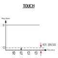
도 13은 도 12의 주파수 노이즈 스펙트럼에서 구동주파수 설정을 설명하기 위한 주파수 노이즈 스펙트럼이다.13 is a frequency noise spectrum for explaining driving frequency setting in the frequency noise spectrum of FIG.
도 13을 참조하면, 노이즈 스펙트럼에서 노이즈가 심한 주파수 대역인 대략 150kHz, 대략 300kHz, 대략 470kHz, 130kHz 내지 180kHz 대역, 260kHz 내지 370kHz 대역, 400kHz 내지 560kHz 대역을 피해서 각각 제1 구동주파수(f0), 제2 구동주파수(f1), 제3 구동주파수(f2), 제4 구동주파수(f3)를 구동한다. 센싱된 신호에서 해당 주파수 크기(Magnitude)의 변화율만 측정하면 노이즈를 회피하여 센싱이 가능하다.Referring to FIG. 13, in the noise spectrum, the first driving frequency f0, the second driving frequency f0, the second driving frequency f0, the second driving frequency f0, and the second driving frequency f0 are respectively avoided in the frequency range of approximately 150 kHz, approximately 300 kHz, approximately 470 kHz, 130 kHz to 180 kHz, 260 kHz to 370 kHz, and 400 kHz to 560 kHz, 2 drive frequency f1, the third drive frequency f2, and the fourth drive frequency f3. By measuring only the rate of change of the magnitude of the frequency in the sensed signal, noise can be avoided and sensing is possible.
이상에서 설명한 바와 같이, 본 발명에 따르면, 인접하는 센싱전극들간의 변위량을 증폭하므로 분해능을 높일 수 있다.As described above, according to the present invention, since the amount of displacement between adjacent sensing electrodes is amplified, the resolution can be increased.
이상에서는 실시예를 참조하여 설명하였지만, 해당 기술 분야의 숙련된 당업자는 하기의 특허 청구의 범위에 기재된 본 발명의 사상 및 영역으로부터 벗어나지 않는 범위 내에서 본 발명을 다양하게 수정 및 변경시킬 수 있음을 이해할 수 있을 것이다.It will be apparent to those skilled in the art that various modifications and variations can be made in the present invention without departing from the spirit or scope of the invention as defined in the appended claims. You will understand.
100, 200, 300 : 터치 센싱 장치110 : 터치 패널
112 : 구동전극114 : 센싱전극
120, 220, 320 : 터치 센싱 콘트롤러 122 : 구동부
124, 224 : 센싱부126 : 제어부
127 : 터치 구동 제어부128 : 터치 센싱 제어부
410, 510 : 차동 수신부420, 520 : 제1 신호 증폭부
430 : 액티브 필터부440 : 제2 신호 증폭부
450 : 아날로그-디지털 변환부460 : 고속 푸리에 변환부
470 : 터치 판별부480 : 노이즈 센싱부100, 200, 300: touch sensing device 110: touch panel
112: driving electrode 114: sensing electrode
120, 220, 320: touch sensing controller 122:
124, 224: sensing unit 126:
127: Touch drive control unit 128: Touch sensing control unit
410, 510:
430
450: analog-to-digital conversion unit 460: fast Fourier transform unit
470: Touch discrimination unit 480: Noise sensing unit
Claims (22)
Translated fromKorean(b) 복수의 센싱전극들을 통해 센싱되는 센싱신호들을 차동적으로 수신하여 터치 발생 여부를 판별하는 단계를 포함하는 터치 센싱 방법.(a) providing a plurality of driving signals having different frequencies to each of a plurality of driving electrodes;
(b) differentially receiving sensing signals sensed through a plurality of sensing electrodes to determine whether a touch is generated.
(b-1) 차동적으로 상기 센싱신호를 수신하여 차동 센싱신호를 생성하는 단계;
(b-2) 상기 차동 센싱신호를 액티브 필터링하는 단계;
(b-3) 액티브 필터링된 센싱신호를 증폭하는 단계;
(b-4) 증폭된 센싱신호를 아날로그-디지털 변환하는 단계;
(b-5) 아날로그-디지털 변환된 센싱신호를 고속 푸리에 변환(FFT) 처리하여 센싱신호의 주파수 크기를 획득하는 단계; 및
(b-6) 고속 푸리에 변환된 센싱신호의 주파수 크기와 상기 구동신호의 주파수 크기간의 변화량을 근거로 터치 발생 여부를 판별하는 단계를 포함하는 터치 센싱 방법.2. The method of claim 1, wherein step (b)
(b-1) receiving the sensing signal differentially to generate a differential sensing signal;
(b-2) actively filtering the differential sensing signal;
(b-3) amplifying the active filtered sensing signal;
(b-4) analog-to-digital converting the amplified sensing signal;
(b-5) performing fast Fourier transform (FFT) processing of the analog-to-digital converted sensing signal to obtain a frequency magnitude of the sensing signal; And
(b-6) determining whether a touch is generated based on a frequency magnitude between a frequency magnitude of the fast Fourier transformed sensing signal and a frequency magnitude of the driving signal.
복수의 센싱전극들을 통해 센싱되는 센싱신호들을 차동적으로 수신하여 터치 발생 여부를 판별하는 센싱부를 포함하는 터치 센싱 콘트롤러.A driving unit for supplying a plurality of driving signals having different frequencies to a plurality of driving electrodes; And
And a sensing unit for differentially receiving sensing signals sensed through the plurality of sensing electrodes to discriminate whether a touch is generated.
상기 구동전극들 각각에 정현파를 제공하는 디지털 함수 발생부를 포함하는 것을 특징으로 하는 터치 센싱 콘트롤러.8. The apparatus according to claim 7,
And a digital function generator for providing a sine wave to each of the driving electrodes.
상기 디지털 함수 발생부는 상기 구동전극들 각각에 연결되어 상기 터치 구동 제어부의 제어에 응답하여 사인파를 정확한 주파수, 주기 및 위상을 정밀하게 발생시키도록 구성된 복수의 직접 디지털 합성(Direct Digital Synthesis, 이하, DDS) 모듈들을 포함하는 것을 특징으로 하는 터치 센싱 콘트롤러.9. The display device according to claim 8, further comprising a touch-
The digital function generator is connected to each of the driving electrodes to perform a plurality of direct digital synthesis (DDS) operations in response to control of the touch drive control unit, which is configured to precisely generate a sine wave with an accurate frequency, ) ≪ / RTI > modules.
상기 커런트 컨베이어 회로의 수는 상기 센싱전극의 수보다 1개 작은 것을 특징으로 하는 터치 센싱 콘트롤러.8. The apparatus of claim 7, wherein the sensing unit includes a plurality of current conveyor circuits for differentially receiving the sensing signals to generate the differential sensing signal,
Wherein the number of the current conveyor circuits is one less than the number of the sensing electrodes.
홀수번째 커런트 컨베이어 회로는, 홀수번째 센싱전극에 연결된 제1 입력단 및 짝수번째 센싱전극에 연결된 제2 입력단을 포함하고,
짝수번째 커런트 컨베이어 회로는, 짝수번째 센싱전극에 연결된 제1 입력단 및 홀수번째 센싱전극에 연결된 제2 입력단을 포함하는 것을 특징으로 하는 터치 센싱 콘트롤러.13. The method of claim 12,
The odd-number current conveyor circuit includes a first input connected to the odd-numbered sensing electrodes and a second input connected to the even-numbered sensing electrodes,
Wherein the even current conveyor circuit includes a first input coupled to the even sensing electrode and a second input coupled to the odd sensing electrode.
상기 커런트 컨베이어 회로의 출력단 각각에 연결된 복수의 신호 증폭기들을 포함하고, 상기 커런트 컨베이어 회로들 각각에서 출력되는 센싱신호를 제1 증폭하는 제1 신호 증폭부;
상기 신호 증폭기들 각각의 출력단에 연결된 복수의 액티브 필터들을 포함하고, 증폭된 센싱신호들 각각을 필터링하는 액티브 필터부;
상기 액티브 필터들 출력단 각각에 연결된 복수의 신호 증폭기들을 포함하고, 상기 액티브 필터링된 센싱 신호들을 제2 증폭하는 제2 신호 증폭부;
복수의 아날로그-디지털 변환기들을 포함하고, 상기 제2 증폭된 센싱신호들 각각을 디지털 변환하는 아날로그-디지털 변환부;
복수의 고속 푸리에 변환기들을 포함하고, 디지털 변환된 센싱신호들 각각을 고속 푸리에 변환하는 고속 푸리에 변환부; 및
상기 구동신호의 주파수 크기를 기준으로 고속 푸리에 변환된 센싱신호의 주파수 크기간의 변화량을 근거로 터치 발생 여부를 판별하는 터치 판별부를 더 포함하는 것을 특징으로 하는 터치 센싱 콘트롤러.14. The apparatus of claim 13,
A first signal amplifying unit including a plurality of signal amplifiers connected to the output terminals of the current conveyor circuit and amplifying a sensing signal output from each of the current conveyor circuits;
An active filter unit including a plurality of active filters connected to output terminals of the signal amplifiers and filtering each of the amplified sensing signals;
A second signal amplifying unit including a plurality of signal amplifiers connected to the output terminals of the active filters, and secondly amplifying the active filtered sensing signals;
An analog-to-digital converter including a plurality of analog-to-digital converters for digitally converting each of the second amplified sensing signals;
A fast Fourier transform unit that includes a plurality of fast Fourier transformers and performs fast Fourier transform on each of the digitally converted sensing signals; And
Further comprising a touch determination unit for determining whether a touch is generated based on a variation amount between frequency magnitudes of a fast Fourier transformed sensing signal based on a frequency magnitude of the driving signal.
상기 커런트 컨베이어 회로의 수는 상기 센싱전극의 수와 동일한 것을 특징으로 하는 터치 센싱 콘트롤러.8. The apparatus of claim 7, wherein the sensing unit includes a plurality of current conveyor circuits for differentially receiving the sensing signals to generate the differential sensing signal,
Wherein the number of the current conveyor circuits is equal to the number of the sensing electrodes.
홀수번째 커런트 컨베이어 회로는 홀수번째 센싱전극에 연결되고, 짝수번째 커런트 컨베이어 회로는 짝수번째 센싱전극에 연결된 것을 특징으로 하는 터치 센싱 콘트롤러.16. The method of claim 15,
Wherein the odd-numbered current conveyor circuit is connected to the odd-numbered sensing electrode, and the even-numbered current conveyor circuit is connected to the even-numbered sensing electrode.
서로 인접하는 커런트 컨베이어 회로의 출력단 각각에 연결된 복수의 신호 증폭기들을 포함하고, 상기 커런트 컨베이어 회로들 각각에서 출력되는 센싱신호를 제1 증폭하는 제1 신호 증폭부;
상기 신호 증폭기들 각각의 출력단에 연결된 복수의 액티브 필터들을 포함하고, 증폭된 센싱신호들 각각을 필터링하는 액티브 필터부;
상기 액티브 필터들 출력단 각각에 연결된 복수의 신호 증폭기들을 포함하고, 상기 액티브 필터링된 센싱 신호들을 제2 증폭하는 제2 신호 증폭부;
복수의 아날로그-디지털 변환기들을 포함하고, 상기 제2 증폭된 센싱신호들 각각을 디지털 변환하는 아날로그-디지털 변환부;
복수의 고속 푸리에 변환기들을 포함하고, 디지털 변환된 센싱신호들 각각을 고속 푸리에 변환하는 고속 푸리에 변환부; 및
상기 구동신호의 주파수 크기를 기준으로 고속 푸리에 변환된 센싱신호의 주파수 크기간의 변화량을 근거로 터치 발생 여부를 판별하는 터치 판별부를 더 포함하는 것을 특징으로 하는 터치 센싱 콘트롤러.17. The apparatus of claim 16, wherein the sensing unit
A first signal amplifying unit including a plurality of signal amplifiers connected to output terminals of current conveyor circuits adjacent to each other, and first amplifying a sensing signal output from each of the current conveyor circuits;
An active filter unit including a plurality of active filters connected to output terminals of the signal amplifiers and filtering each of the amplified sensing signals;
A second signal amplifying unit including a plurality of signal amplifiers connected to the output terminals of the active filters, and secondly amplifying the active filtered sensing signals;
An analog-to-digital converter including a plurality of analog-to-digital converters for digitally converting each of the second amplified sensing signals;
A fast Fourier transform unit that includes a plurality of fast Fourier transformers and performs fast Fourier transform on each of the digitally converted sensing signals; And
Further comprising a touch determination unit for determining whether a touch is generated based on a variation amount between frequency magnitudes of a fast Fourier transformed sensing signal based on a frequency magnitude of the driving signal.
첫번째 센싱전극에 연결된 커런트 컨베이어 회로는 플로팅된 제1 출력단 및 첫번째 신호 증폭기에 연결된 제2 출력단을 포함하고,
마지막번째 센싱전극에 연결된 커런트 컨베이어 회로는 마지막번째 신호 증폭기에 연결된 제1 출력단 및 플로팅된 제2 출력단을 포함하는 것을 특징으로 하는 터치 센싱 콘트롤러.18. The method of claim 17,
The current conveyor circuit connected to the first sensing electrode includes a first output terminal floating and a second output terminal connected to the first signal amplifier,
And the current conveyor circuit connected to the last sensing electrode comprises a first output connected to the last signal amplifier and a second output connected to the second sensing amplifier.
상기 구동전극들에 서로 다른 주파수를 갖는 복수의 구동신호들을 제공하는 구동부와, 상기 센싱전극들을 통해 센싱되는 센싱신호들을 차동적으로 수신하여 터치 발생 여부를 판별하는 센싱부를 포함하는 터치 센싱 콘트롤러를 포함하는 것을 특징으로 하는 터치 센싱 장치.A touch panel including a plurality of driving electrodes and a plurality of sensing electrodes; And
A driving unit for providing a plurality of driving signals having different frequencies to the driving electrodes, and a sensing unit for receiving the sensing signals sensed through the sensing electrodes to discriminate whether a touch is generated or not The touch sensing device comprising:
Priority Applications (1)
| Application Number | Priority Date | Filing Date | Title |
|---|---|---|---|
| KR1020150153974AKR102417379B1 (en) | 2015-11-03 | 2015-11-03 | Touch sensing controller and touch sensing device having the same |
Applications Claiming Priority (1)
| Application Number | Priority Date | Filing Date | Title |
|---|---|---|---|
| KR1020150153974AKR102417379B1 (en) | 2015-11-03 | 2015-11-03 | Touch sensing controller and touch sensing device having the same |
Publications (2)
| Publication Number | Publication Date |
|---|---|
| KR20170052051Atrue KR20170052051A (en) | 2017-05-12 |
| KR102417379B1 KR102417379B1 (en) | 2022-07-07 |
Family
ID=58740462
Family Applications (1)
| Application Number | Title | Priority Date | Filing Date |
|---|---|---|---|
| KR1020150153974AActiveKR102417379B1 (en) | 2015-11-03 | 2015-11-03 | Touch sensing controller and touch sensing device having the same |
Country Status (1)
| Country | Link |
|---|---|
| KR (1) | KR102417379B1 (en) |
Cited By (6)
| Publication number | Priority date | Publication date | Assignee | Title |
|---|---|---|---|---|
| CN109766031A (en)* | 2017-11-10 | 2019-05-17 | 辛纳普蒂克斯公司 | AFE(analog front end) (AFE) for quantizing noise limiting sensor device |
| KR20190126959A (en)* | 2018-05-02 | 2019-11-13 | 삼성디스플레이 주식회사 | Touch panel |
| KR20190136309A (en)* | 2018-05-30 | 2019-12-10 | 엘지디스플레이 주식회사 | Touch system, touch circuit, and touch sensing method |
| KR20210050285A (en)* | 2019-10-28 | 2021-05-07 | 엘지디스플레이 주식회사 | Touch circuit, touch display device, and touch driving method thereof |
| KR102348144B1 (en)* | 2020-12-11 | 2022-01-07 | 주식회사 지니틱스 | Touch input sensing device with current conveyor |
| WO2024207964A1 (en)* | 2023-04-04 | 2024-10-10 | 京东方科技集团股份有限公司 | Front-end circuit suitable for touch panel, front-end identification circuit, and display device |
Citations (7)
| Publication number | Priority date | Publication date | Assignee | Title |
|---|---|---|---|---|
| KR20070006725A (en)* | 2003-12-31 | 2007-01-11 | 쓰리엠 이노베이티브 프로퍼티즈 컴파니 | Touch-sensitive device with flexural wave vibration detection and excitation transducer |
| KR20110134886A (en) | 2009-03-26 | 2011-12-15 | 사이프레스 세미컨덕터 코포레이션 | Multi-function capacitance sensing circuit with current conveyor |
| JP2012514264A (en)* | 2008-12-30 | 2012-06-21 | エスティー‐エリクソン、オサケ、ユキチュア | Touch screen controller |
| KR20120095376A (en) | 2009-10-08 | 2012-08-28 | 쓰리엠 이노베이티브 프로퍼티즈 컴파니 | Multi-touch touch device with multiple drive frequencies and maximum likelihood estimation |
| KR20140071049A (en)* | 2012-12-03 | 2014-06-11 | 삼성전자주식회사 | Capacitive multi-touch system and method of determining low noise driving frequency |
| KR20150026001A (en)* | 2013-08-30 | 2015-03-11 | 주식회사 실리콘웍스 | Touch system and control method thereof |
| KR20150095391A (en)* | 2014-02-13 | 2015-08-21 | 충북대학교 산학협력단 | Method and Apparatus of touch screen control using frequency division sensing |
- 2015
- 2015-11-03KRKR1020150153974Apatent/KR102417379B1/enactiveActive
Patent Citations (7)
| Publication number | Priority date | Publication date | Assignee | Title |
|---|---|---|---|---|
| KR20070006725A (en)* | 2003-12-31 | 2007-01-11 | 쓰리엠 이노베이티브 프로퍼티즈 컴파니 | Touch-sensitive device with flexural wave vibration detection and excitation transducer |
| JP2012514264A (en)* | 2008-12-30 | 2012-06-21 | エスティー‐エリクソン、オサケ、ユキチュア | Touch screen controller |
| KR20110134886A (en) | 2009-03-26 | 2011-12-15 | 사이프레스 세미컨덕터 코포레이션 | Multi-function capacitance sensing circuit with current conveyor |
| KR20120095376A (en) | 2009-10-08 | 2012-08-28 | 쓰리엠 이노베이티브 프로퍼티즈 컴파니 | Multi-touch touch device with multiple drive frequencies and maximum likelihood estimation |
| KR20140071049A (en)* | 2012-12-03 | 2014-06-11 | 삼성전자주식회사 | Capacitive multi-touch system and method of determining low noise driving frequency |
| KR20150026001A (en)* | 2013-08-30 | 2015-03-11 | 주식회사 실리콘웍스 | Touch system and control method thereof |
| KR20150095391A (en)* | 2014-02-13 | 2015-08-21 | 충북대학교 산학협력단 | Method and Apparatus of touch screen control using frequency division sensing |
Cited By (7)
| Publication number | Priority date | Publication date | Assignee | Title |
|---|---|---|---|---|
| CN109766031A (en)* | 2017-11-10 | 2019-05-17 | 辛纳普蒂克斯公司 | AFE(analog front end) (AFE) for quantizing noise limiting sensor device |
| CN109766031B (en)* | 2017-11-10 | 2024-04-30 | 辛纳普蒂克斯公司 | Analog Front End (AFE) for quantization noise limited sensor device |
| KR20190126959A (en)* | 2018-05-02 | 2019-11-13 | 삼성디스플레이 주식회사 | Touch panel |
| KR20190136309A (en)* | 2018-05-30 | 2019-12-10 | 엘지디스플레이 주식회사 | Touch system, touch circuit, and touch sensing method |
| KR20210050285A (en)* | 2019-10-28 | 2021-05-07 | 엘지디스플레이 주식회사 | Touch circuit, touch display device, and touch driving method thereof |
| KR102348144B1 (en)* | 2020-12-11 | 2022-01-07 | 주식회사 지니틱스 | Touch input sensing device with current conveyor |
| WO2024207964A1 (en)* | 2023-04-04 | 2024-10-10 | 京东方科技集团股份有限公司 | Front-end circuit suitable for touch panel, front-end identification circuit, and display device |
Also Published As
| Publication number | Publication date |
|---|---|
| KR102417379B1 (en) | 2022-07-07 |
Similar Documents
| Publication | Publication Date | Title |
|---|---|---|
| KR101628894B1 (en) | Touch sensing method, touch sensing controller and touch sensing device | |
| KR102417379B1 (en) | Touch sensing controller and touch sensing device having the same | |
| US8841927B2 (en) | Touch sensing circuit | |
| JP6280198B2 (en) | Capacitance-based touch device with reduced interference and method thereof | |
| US10296109B2 (en) | Stylus for operating a digitizer system | |
| US9857932B2 (en) | Capacitive touch sense architecture having a correlator for demodulating a measured capacitance from an excitation signal | |
| EP3640780B1 (en) | Capacitance detection circuit, touch-control chip and electronic device | |
| CN103150072B (en) | Touch device and touch method thereof | |
| EP3379271B1 (en) | Capacitance detection apparatus, electronic device and force detection apparatus | |
| US11402945B2 (en) | Touch sensing method and touch sensing device based on driving and sensing signals | |
| US20190042029A1 (en) | Control chip for touch panel with high sensitivity and operating method thereof | |
| US10228797B2 (en) | Continuous time anti-alias filter for capacitive touch sensing | |
| CN105452998A (en) | Method of multi-zone capacitive sensing, device and apparatus implementing the method | |
| CN104679366A (en) | capacitive touch system | |
| US9606671B2 (en) | Capacitive sensing device capable of eliminating influence from mutual capacitance and operating method thereof | |
| US11592936B2 (en) | Capacitive touch device with high sensitivity and low power consumption | |
| JP5852818B2 (en) | Touch panel controller, input device using the same, and electronic device | |
| EP3285204A1 (en) | Touch detection circuit, fingerprint module and control method thereof | |
| CN113316759B (en) | Capacitance detection circuit, touch chip and electronic equipment | |
| KR101681747B1 (en) | Touch sensing method, touch sensing controller and touch sensing device | |
| JP4941938B2 (en) | Capacitance change detection circuit, touch panel, and determination method | |
| KR101209114B1 (en) | Apparatus for sensing charge of touch panel with removing low frequency noise | |
| KR101763139B1 (en) | Touch sensing method, touch sensing controller and touch sensing device having the same | |
| KR101531652B1 (en) | Digitizer and Method for filtering noise thereof | |
| TW201635126A (en) | Capacitive touch device with high sensitivity and operating method thereof |
Legal Events
| Date | Code | Title | Description |
|---|---|---|---|
| PA0109 | Patent application | Patent event code:PA01091R01D Comment text:Patent Application Patent event date:20151103 | |
| PG1501 | Laying open of application | ||
| A201 | Request for examination | ||
| PA0201 | Request for examination | Patent event code:PA02012R01D Patent event date:20201103 Comment text:Request for Examination of Application Patent event code:PA02011R01I Patent event date:20151103 Comment text:Patent Application | |
| E902 | Notification of reason for refusal | ||
| PE0902 | Notice of grounds for rejection | Comment text:Notification of reason for refusal Patent event date:20211231 Patent event code:PE09021S01D | |
| E701 | Decision to grant or registration of patent right | ||
| PE0701 | Decision of registration | Patent event code:PE07011S01D Comment text:Decision to Grant Registration Patent event date:20220526 | |
| PR0701 | Registration of establishment | Comment text:Registration of Establishment Patent event date:20220701 Patent event code:PR07011E01D | |
| PR1002 | Payment of registration fee | Payment date:20220704 End annual number:3 Start annual number:1 | |
| PG1601 | Publication of registration |