KR20170050924A - Small gimbal for controlling 3-rotation axis - Google Patents
Small gimbal for controlling 3-rotation axisDownload PDFInfo
- Publication number
- KR20170050924A KR20170050924AKR1020150153073AKR20150153073AKR20170050924AKR 20170050924 AKR20170050924 AKR 20170050924AKR 1020150153073 AKR1020150153073 AKR 1020150153073AKR 20150153073 AKR20150153073 AKR 20150153073AKR 20170050924 AKR20170050924 AKR 20170050924A
- Authority
- KR
- South Korea
- Prior art keywords
- axis
- lens barrel
- rolling
- support
- gimbal
- Prior art date
- Legal status (The legal status is an assumption and is not a legal conclusion. Google has not performed a legal analysis and makes no representation as to the accuracy of the status listed.)
- Ceased
Links
Images


Classifications
- B—PERFORMING OPERATIONS; TRANSPORTING
- B64—AIRCRAFT; AVIATION; COSMONAUTICS
- B64D—EQUIPMENT FOR FITTING IN OR TO AIRCRAFT; FLIGHT SUITS; PARACHUTES; ARRANGEMENT OR MOUNTING OF POWER PLANTS OR PROPULSION TRANSMISSIONS IN AIRCRAFT
- B64D47/00—Equipment not otherwise provided for
- B64D47/08—Arrangements of cameras
- B—PERFORMING OPERATIONS; TRANSPORTING
- B64—AIRCRAFT; AVIATION; COSMONAUTICS
- B64C—AEROPLANES; HELICOPTERS
- B64C39/00—Aircraft not otherwise provided for
- B64C39/02—Aircraft not otherwise provided for characterised by special use
- B64C39/024—Aircraft not otherwise provided for characterised by special use of the remote controlled vehicle type, i.e. RPV
- B—PERFORMING OPERATIONS; TRANSPORTING
- B64—AIRCRAFT; AVIATION; COSMONAUTICS
- B64U—UNMANNED AERIAL VEHICLES [UAV]; EQUIPMENT THEREFOR
- B64U20/00—Constructional aspects of UAVs
- B64U20/80—Arrangement of on-board electronics, e.g. avionics systems or wiring
- B64U20/87—Mounting of imaging devices, e.g. mounting of gimbals
- F—MECHANICAL ENGINEERING; LIGHTING; HEATING; WEAPONS; BLASTING
- F16—ENGINEERING ELEMENTS AND UNITS; GENERAL MEASURES FOR PRODUCING AND MAINTAINING EFFECTIVE FUNCTIONING OF MACHINES OR INSTALLATIONS; THERMAL INSULATION IN GENERAL
- F16M—FRAMES, CASINGS OR BEDS OF ENGINES, MACHINES OR APPARATUS, NOT SPECIFIC TO ENGINES, MACHINES OR APPARATUS PROVIDED FOR ELSEWHERE; STANDS; SUPPORTS
- F16M11/00—Stands or trestles as supports for apparatus or articles placed thereon ; Stands for scientific apparatus such as gravitational force meters
- F16M11/02—Heads
- F16M11/04—Means for attachment of apparatus; Means allowing adjustment of the apparatus relatively to the stand
- F16M11/06—Means for attachment of apparatus; Means allowing adjustment of the apparatus relatively to the stand allowing pivoting
- F16M11/12—Means for attachment of apparatus; Means allowing adjustment of the apparatus relatively to the stand allowing pivoting in more than one direction
- F16M11/121—Means for attachment of apparatus; Means allowing adjustment of the apparatus relatively to the stand allowing pivoting in more than one direction constituted of several dependent joints
- F16M11/123—Means for attachment of apparatus; Means allowing adjustment of the apparatus relatively to the stand allowing pivoting in more than one direction constituted of several dependent joints the axis of rotation intersecting in a single point, e.g. by using gimbals
- F—MECHANICAL ENGINEERING; LIGHTING; HEATING; WEAPONS; BLASTING
- F16—ENGINEERING ELEMENTS AND UNITS; GENERAL MEASURES FOR PRODUCING AND MAINTAINING EFFECTIVE FUNCTIONING OF MACHINES OR INSTALLATIONS; THERMAL INSULATION IN GENERAL
- F16M—FRAMES, CASINGS OR BEDS OF ENGINES, MACHINES OR APPARATUS, NOT SPECIFIC TO ENGINES, MACHINES OR APPARATUS PROVIDED FOR ELSEWHERE; STANDS; SUPPORTS
- F16M13/00—Other supports for positioning apparatus or articles; Means for steadying hand-held apparatus or articles
- F16M13/02—Other supports for positioning apparatus or articles; Means for steadying hand-held apparatus or articles for supporting on, or attaching to, an object, e.g. tree, gate, window-frame, cycle
- G—PHYSICS
- G03—PHOTOGRAPHY; CINEMATOGRAPHY; ANALOGOUS TECHNIQUES USING WAVES OTHER THAN OPTICAL WAVES; ELECTROGRAPHY; HOLOGRAPHY
- G03B—APPARATUS OR ARRANGEMENTS FOR TAKING PHOTOGRAPHS OR FOR PROJECTING OR VIEWING THEM; APPARATUS OR ARRANGEMENTS EMPLOYING ANALOGOUS TECHNIQUES USING WAVES OTHER THAN OPTICAL WAVES; ACCESSORIES THEREFOR
- G03B15/00—Special procedures for taking photographs; Apparatus therefor
- G03B15/006—Apparatus mounted on flying objects
- G—PHYSICS
- G03—PHOTOGRAPHY; CINEMATOGRAPHY; ANALOGOUS TECHNIQUES USING WAVES OTHER THAN OPTICAL WAVES; ELECTROGRAPHY; HOLOGRAPHY
- G03B—APPARATUS OR ARRANGEMENTS FOR TAKING PHOTOGRAPHS OR FOR PROJECTING OR VIEWING THEM; APPARATUS OR ARRANGEMENTS EMPLOYING ANALOGOUS TECHNIQUES USING WAVES OTHER THAN OPTICAL WAVES; ACCESSORIES THEREFOR
- G03B17/00—Details of cameras or camera bodies; Accessories therefor
- G03B17/56—Accessories
- G03B17/561—Support related camera accessories
- G03B17/568—
- B64C2201/127—
- B—PERFORMING OPERATIONS; TRANSPORTING
- B64—AIRCRAFT; AVIATION; COSMONAUTICS
- B64U—UNMANNED AERIAL VEHICLES [UAV]; EQUIPMENT THEREFOR
- B64U2101/00—UAVs specially adapted for particular uses or applications
- B64U2101/30—UAVs specially adapted for particular uses or applications for imaging, photography or videography
Landscapes
- Engineering & Computer Science (AREA)
- General Engineering & Computer Science (AREA)
- Mechanical Engineering (AREA)
- Physics & Mathematics (AREA)
- General Physics & Mathematics (AREA)
- Aviation & Aerospace Engineering (AREA)
- Microelectronics & Electronic Packaging (AREA)
- Remote Sensing (AREA)
- Accessories Of Cameras (AREA)
- Studio Devices (AREA)
Abstract
Translated fromKoreanDescription
Translated fromKorean본 발명의 다양한 실시예는 카메라를 수평 자세로 유지하는 3축 조정 촬영 기구물에 관한 것이다.Various embodiments of the invention relate to a three-axis adjusting imaging device that maintains the camera in a horizontal posture.
종래 기술의 수평 자세 유지 촬영 기구물(이하 짐벌이라 한다)은 2축 조정, 3축 조정이 대부분으로 설계 되어 왔다. 조정 축의 수에 따라 구동부의 수가 정해지며, 세로 Z축 회전을 요잉(YAWING), X축 조정을 피칭(PITCHING), Y축 조정을 롤링(ROLLING)으로 정의할 수 있다.Conventionally, the horizontal posture maintaining mechanism (hereinafter referred to as a gimbals) has been designed to have two-axis adjustment and three-axis adjustment. The number of driving portions is determined according to the number of adjustment shafts, and the longitudinal Z-axis rotation is defined as YAWING, the X-axis adjustment is defined as PITCHING, and the Y-axis adjustment is defined as ROLLING.
각 축 마다 구동부가 있어 수평 유지를 위해 동작 하며, 회전 축이 단계 별로 다음 축 회전 운동에 포함 되어 있다. Z축이 회전을 하면 X축, Y축 구동부 및 구조물도 동시에 회전이 되고, Y축이 회전 하면, X축 구조물도 같이 회전하게 되고, X축은 X축 관련 구조물만 회전이 되도록 구성을 한다.Each axis has a driving part and operates to maintain the horizontal position, and the rotation axis is included in the next axis rotation motion step by step. When the Z-axis rotates, the X-axis, Y-axis drive, and structure are simultaneously rotated. When the Y-axis rotates, the X-axis structure rotates together, and the X-axis rotates only the X-axis related structure.
종래 기술은 별도의 카메라를 짐벌(GIMBAL)에 장착 하는 구조로 설계 되어 있으며, 카메라는 최종 회전 축인 X축 끝에 고정 장착 되도록 되어 있다.In the prior art, a separate camera is designed to be mounted on a gimbal, and the camera is fixedly mounted on the end of the X axis which is the final rotation axis.
대형 카메라 장착용 짐벌은 축 지지대를 양끝에 구성 하기도 하지만, 소형 카메라용 짐벌은 구동부가 있는 곳만 회전 축으로 사용한다.The gimbal for mounting a large-sized camera may constitute the shaft support at both ends, but the gimbal for a small camera is used as a rotation shaft only where the driving part exists.
종래 기술의 짐벌에는 구동부로 브러쉬리스 모터(BRUSHLESS MOTOR)를 대부분 사용하며 제어부에 의해 정밀 제어를 한다.Conventionally, a brushless motor (BRUSHLESS MOTOR) is mostly used as a driving unit for a gimbal, and precision control is performed by a control unit.
하지만, 종래 기술은 카메라를 장착용으로 초소형 카메라 모듈에는 적용이 불가하며, 초소형 렌즈를 사용한 드론(DRONE)은 짐벌 기능이 없다.However, the prior art can not be applied to an ultra-small camera module for mounting a camera, and a DRONE using an ultra-small lens has no gimbal function.
종래 기술의 짐벌은 일반적인 카메라를 장착하여 사용하는 방법이며 크기가 크며 가격이 비싸고 브러쉬리스 모터(BRUSHLESS MOTOR)사용으로 무겁다. 그렇기 때문에 비행을 위한 드론은 대형으로 구성이 되어야 안정적인 비행 및 촬영이 가능할 수 있다.The conventional gimbal is a method of using a general camera and is large in size, expensive, and heavy due to the use of a brushless motor. Therefore, the drones for flying should be large-sized so that stable flight and shooting can be possible.
또한, 현재 소형 카메라 모듈이 장착된 드론에는 짐벌 기능이 없다.Also, the drones equipped with a small camera module currently do not have a gimbal function.
본 발명의 다양한 실시예는 소형 카메라 모듈과 짐벌 기능을 일체화 시켜 작은 비용과 가벼운 무게로 소형 드론(DRONE)으로 대형 짐벌과 대형 카메라 및 대형 드론을 이용하여 촬영한 영상과 유사한 고급 영상 촬영이 가능하도록 하는 것을 목적으로 한다.Various embodiments of the present invention integrate a miniature camera module and a gimbals function to enable high-quality image capture similar to that taken with a large gimbal, a large camera, and a large dron with a small cost and a light weight with a small drone .
본 발명의 다양한 실시예는 3축 짐벌에 있어서, 제1지지체; 렌즈군을 포함하되, 상기 제1지지체에 제1축을 중심으로 회전가능하게 결합된 렌즈 배럴; 상기 렌즈 배럴 제1위치에 장착되어, 상기 렌즈군을 제1축과 수직인 제2축을 중심으로 회전하는 힘을 제공하는 롤링 구동부; 상기 제1지지체에 장착되어, 상기 렌즈 베럴을 상기 제1축을 중심으로 회전하는 힘을 제공하는 피칭 구동부; 상기 제1지지체에 상기 제1,2축과 각각 수직인 제3축을 중심으로 회전가능하게 결합된 제2지지체; 및 상기 제2지지체에 장착되어 상기 제1지지체를 상기 제3축을 중심으로 회전하게 하는 요잉 구동부를 포함할 수 있다.Various embodiments of the present invention are directed to a three axis gimbal comprising: a first support; A lens barrel including a lens group, the lens barrel being rotatably coupled to the first support body about a first axis; A rolling driver mounted on the lens barrel at a first position to provide a force to rotate the lens group about a second axis perpendicular to the first axis; A pitching driver mounted on the first support to provide a force to rotate the lens barrel about the first axis; A second support rotatably coupled to the first support body about a third axis perpendicular to the first and second axes; And a yaw driving unit mounted on the second support body and rotating the first support body about the third axis.
본 발명의 다양한 실시예는 3축 짐벌에 있어서, 적어도 하나 이상의 지지체; 및 상기 지지체에 장착되어, 3개의 회전축을 중심으로 각각 회전가능하게 결합된 렌즈 배럴을 포함하되, 상기 렌즈 배럴은 회전 부재; 및 상기 회전 부재의 표면에서 광축을 중심으로 회전하는 롤링부를 포함하며, 상기 롤링부는 상기 회전 부재에 제1면에 배치된 제1롤러들을 포함하는 제1롤링부; 및 상기 회전부재 제1면과 반대방향의 제2면에 배치된 제2롤러들을 포함하는 제2롤링부를 포함할 수 있다.Various embodiments of the present invention are directed to a three-axis gimbal, comprising: at least one support; And a lens barrel mounted on the support and rotatably coupled to each of the three rotation shafts, the lens barrel including: a rotary member; And a rolling unit rotating around an optical axis at a surface of the rotating member, wherein the rolling unit includes a first rolling unit including first rollers disposed on a first surface of the rotating member; And a second rolling part including second rollers disposed on a second surface opposite to the first surface of the rotary member.
본 발명의 다양한 실시예는 3축 짐벌에 있어서, 지지체; 및 상기 지지체에 장착되어, 3개의 회전축을 중심으로 각각 회전가능하게 결합된 렌즈 배럴을 포함하고, 상기 렌즈 배럴은 회전 부재; 및 상기 회전 부재 사이에 배치되는 롤링부를 포함하며, 상기 렌즈 배럴 외주면에 롤링 구동부가 결합되되, 상기 롤링 구동부는 회전 부재와 맞물리게 장착될 수 있다.Various embodiments of the present invention provide a three-axis gimbal comprising: a support; And a lens barrel attached to the support and rotatably coupled to each of the three rotation shafts, the lens barrel comprising: a rotary member; And a rolling unit disposed between the rotating members, wherein a rolling driving unit is coupled to an outer circumferential surface of the lens barrel, and the rolling driving unit can be mounted to be engaged with the rotating member.
본 발명의 다양한 실시예에 따른 3축 카메라 짐벌은 소형이면서 경량으로 구성되어서, 드론과 같은 무인 비행체에 실장할 수 있다.The three-axis camera gimbals according to various embodiments of the present invention are compact and lightweight, and can be mounted on a unmanned aerial vehicle such as a drone.
본 발명의 다양한 실시예에 따른 3축 카메라 짐벌은 적어도 3대의 롤러를 이용한 회전 작동에 따른 마찰 저항을 최소화할 수 있다.The three-axis camera gimbals according to various embodiments of the present invention can minimize frictional resistance due to rotational operation using at least three rollers.
본 발명의 다양한 실시예에 따른 3축 카메라 짐벌은 적어도 3대의 롤러를 회전부재 전후면에 각각 배치하여, 안정적인 렌즈부의 롤링 동작을 구현할 수 있다.The three-axis camera gimbals according to various embodiments of the present invention can arrange at least three rollers on the front and rear surfaces of the rotating member to realize a stable rolling operation of the lens unit.
본 발명의 다양한 실시예에 따른 3축 카메라 짐벌은 FPCB 변곡점 이동에 따른 회전축에 FPCB를 구성할 수 있다.The three-axis camera gimbals according to various embodiments of the present invention can configure the FPCB on the rotation axis due to the FPCB inflection point movement.
본 발명의 다양한 실시예에 따른 3축 카메라 짐벌은 각각의 구동부(롤링 구동부, 피칭 구동부, 요잉 구동부)에 공용 기어를 한 개 이상 사용하여 부품수 및 재료비를 절감할 수 있다.The three-axis camera gimbals according to various embodiments of the present invention can reduce the number of components and material cost by using one or more common gears in each of the driving units (rolling driving unit, pitching driving unit, yawing driving unit).
도 1은 본 발명의 다양한 실시예에 따른 3축 카메라 짐벌의 전면을 나타내는 사시도이다.
도 2는 본 발명의 다양한 실시예에 따른 3축 카메라 짐벌의 후면을 나타내는 사시도이다.
도 3은 본 발명의 다양한 실시예에 따른 롤링 구동부, 피칭 구동부 및 렌즈 배럴의 장착 상태를 나타내는 사시도이다.
도 4는 도 3의 정면도이다.
도 5a는 본 발명의 다양한 실시예에 따른 요잉 구동부가 장착된 제2지지체를 위에서본 상태를 나타내는 사시도이다.
도 5b 본 발명의 다양한 실시예에 따른 요잉 구동부가 장착된 제2지지체를 아래에서 본 상태를 나타내는 사시도이다.
도 6a는 본 발명의 다양한 실시예에 따른 3축 카메라 짐벌에 채용된 롤링 구동부의 구성을 나타내는 사시도이다.
도 6b는 본 발명의 다양한 실시예에 따른 렌즈 배럴 외주면에 장착된 롤링 구동부의 연동 상태를 나타내는 사시도이다.
도 7은 본 발명의 다양한 실시예에 따른 3축 카메라 짐벌에 채용된 피칭 구동부의 구성을 나타내는 사시도이다.
도 8은 본 발명의 다양한 실시예에 따른 3축 카메라 짐벌에 채용된 요잉 구동부의 구성을 나타내는 사시도이다.
도 9는 본 발명의 다양한 실시예에 따른 렌즈 배럴에 구성된 롤링부의 장착 상태를 나타내는 사시도이다.
도 10은 본 발명의 다양한 실시예에 따른 렌즈 배럴의 구성을 단면으로 나타내는 사시도이다.
도 11은 본 발명의 다양한 실시예에 따른 제1지지체의 결합 상태를 나타내는 사시도이다.
도 12는 본 발명의 다양한 실시예에 따른 제1지지체의 결합 상태를 나타내는 단면도이다.1 is a perspective view illustrating a front surface of a three-axis camera gimbals according to various embodiments of the present invention.
2 is a perspective view showing a rear surface of a three-axis camera gimbals according to various embodiments of the present invention.
3 is a perspective view illustrating a mounting state of a rolling driver, a pitching driver, and a lens barrel according to various embodiments of the present invention.
4 is a front view of Fig.
FIG. 5A is a perspective view showing a state in which the second support having the yaw driving part mounted thereon is viewed from above, according to various embodiments of the present invention. FIG.
FIG. 5B is a perspective view showing a state in which a second support body equipped with a yawing drive unit according to various embodiments of the present invention is viewed from below. FIG.
6A is a perspective view showing a configuration of a rolling driver employed in a 3-axis camera gimbal according to various embodiments of the present invention.
6B is a perspective view illustrating an interlocked state of a rolling driving unit mounted on an outer circumferential surface of a lens barrel according to various embodiments of the present invention.
7 is a perspective view showing a configuration of a pitching driver employed in a 3-axis camera gimbal according to various embodiments of the present invention.
FIG. 8 is a perspective view showing a structure of a yaw driving part employed in a 3-axis camera gimbal according to various embodiments of the present invention. FIG.
9 is a perspective view showing a mounting state of a rolling part constituted in a lens barrel according to various embodiments of the present invention.
10 is a perspective view showing, in cross section, the configuration of a lens barrel according to various embodiments of the present invention.
11 is a perspective view showing a state of engagement of a first support according to various embodiments of the present invention.
12 is a cross-sectional view showing a state of engagement of a first support according to various embodiments of the present invention.
이하, 본 개시의 다양한 실시예가 첨부된 도면을 참조하여 기재된다. 그러나, 이는 본 개시를 특정한 실시 형태에 대해 한정하려는 것이 아니며, 본 개시의 실시예의 다양한 변경(modification), 균등물(equivalent), 및/또는 대체물(alternative)을 포함하는 것으로 이해되어야 한다. 도면의 설명과 관련하여, 유사한 구성요소에 대해서는 유사한 참조 부호가 사용될 수 있다.Hereinafter, various embodiments of the present disclosure will be described with reference to the accompanying drawings. It should be understood, however, that this disclosure is not intended to limit the present disclosure to the particular embodiments, but includes various modifications, equivalents, and / or alternatives of the embodiments of the present disclosure. In connection with the description of the drawings, like reference numerals may be used for similar components.
본 문서에서, "가진다," "가질 수 있다,""포함한다," 또는 "포함할 수 있다" 등의 표현은 해당 특징(예:수치, 기능, 동작, 또는 부품 등의 구성요소)의 존재를 가리키며, 추가적인 특징의 존재를 배제하지 않는다.In this document, the expressions "having," " having, "" comprising," or &Quot;, and does not exclude the presence of additional features.
본 문서에서, "A 또는 B,""A 또는/및 B 중 적어도 하나,"또는 "A 또는/및 B 중 하나 또는 그 이상" 등의 표현은 함께 나열된 항목들의 모든 가능한 조합을 포함할 수 있다. 예를 들면, "A 또는 B," A 및 B 중 적어도 하나,"또는 " A 또는 B 중 적어도 하나"는, (1) 적어도 하나의 A를 포함, (2) 적어도 하나의 B를 포함, 또는 (3) 적어도 하나의 A 및 적어도 하나의 B 모두를 포함하는 경우를 모두 지칭할 수 있다.In this document, the expressions "A or B," "at least one of A or / and B," or "one or more of A and / or B," etc. may include all possible combinations of the listed items . For example, "A or B," "at least one of A and B," or "at least one of A or B" includes (1) at least one A, (2) at least one B, (3) at least one A and at least one B all together.
다양한 실시예에서 사용된 "제 1,""제 2,""첫째,"또는"둘째,"등의 표현들은 다양한 구성요소들을, 순서 및/또는 중요도에 상관없이 수식할 수 있고, 해당 구성요소들을 한정하지 않는다. 상기 표현들은 한 구성요소를 다른 구성요소와 구분하기 위해 사용될 수 있다. 예를 들면, 제1사용자 기기와 제2사용자 기기는, 순서 또는 중요도와 무관하게, 서로 다른 사용자 기기를 나타낼 수 있다. 예를 들면, 본 개시의 권리 범위를 벗어나지 않으면서 제 1 구성요소는 제 2 구성요소로 명명될 수 있고, 유사하게 제 2 구성요소도 제 1 구성요소로 바꾸어 명명될 수 있다.The terms "first," "second," "first," or "second," etc. used in various embodiments may describe various components in any order and / or importance, Lt; / RTI > The representations may be used to distinguish one component from another. For example, the first user equipment and the second user equipment may represent different user equipment, regardless of order or importance. For example, without departing from the scope of the present disclosure, the first component may be referred to as a second component, and similarly, the second component may be named as the first component.
어떤 구성요소(예: 제 1 구성요소)가 다른 구성요소(예: 제 2 구성요소)에 "(기능적으로 또는 통신적으로) 연결되어 ((operatively or communicatively) coupled with/to)" 있다거나, "접속되어 (connected to)" 있다고 언급된 때에는, 상기 어떤 구성요소가 상기 다른 구성요소에 직접적으로 연결되거나, 다른 구성요소(예:제 3 구성요소)를 통하여 연결될 수 있다고 이해되어야 할 것이다. 반면에, 어떤 구성요소 (예: 제 1 구성요소)가 다른 구성요소 (예: 제 2 구성요소)에 "직접 연결되어" 있다거나 "직접 접속되어" 있다고 언급된 때에는, 상기 어떤 구성요소와 상기 다른 구성요소 사이에 다른 구성요소(예: 제 3 구성요소)가 존재하지 않는 것으로 이해될 수 있다.It is also possible that a component (eg, a first component) is "(operatively or communicatively coupled) / to" another component (eg, a second component) It is to be understood that when an element is referred to as being "connected to ", it is to be understood that the element may be directly connected to the other element or may be connected through another element (e.g., a third element). On the other hand, when it is mentioned that a component (e.g., a first component) is "directly connected" or "directly connected" to another component (e.g., a second component) It can be understood that there is no other component (e.g., a third component) between other components.
본 문서에서 사용된 표현 "~하도록 구성된 (또는 설정된)(configured to)"은 상황에 따라, 예를 들면, "~에 적합한 (suitable for)," "하는 능력을 가지는 (having the capacity to)," "하도록 설계된 (designed to)," "하도록 변경된 (adapted to)," "~하도록 만들어진 (made to)," 또는 "~를 할 수 있는(capable of)"과 바꾸어 사용될 수 있다. 용어 "~하도록 구성 (또는 설정)된"은 하드웨어적으로 "특별히 설계된(specifically designed to) 것만 반드시 의미하지 않을 수 있다. 대신, 어떤 상황에서는, "~하도록 구성된 장치" 라는 표현은, 그 장치가 다른 장치 또는 부품들과 함께 "~할 수 있는"것을 의미할 수 있다. 예를 들면, 문구 A, B, 및 C를 수행하도록 구성(또는 설정)된 프로세서"는 해당 동작을 수행하기 위한 전용 프로세서(예: 임베디드 프로세서), 또는 메모리 장치에 저장된 하나 이상의 소프트웨어 프로그램들을 실행함으로써, 해당 동작들을 수행할 수 있는 범용 프로세서(generic-purpose processor)(예: CPU 또는 application processor)를 의미할 수 있다.The phrase " configured to " as used herein is intended to encompass, depending on the context, for example, having the ability to be suitable for, The present invention may be used interchangeably with "designed to," "adapted to," "made to," or "capable of". The term " configured to (or configured) "may not necessarily mean specifically designed to be" specifically designed. "Instead, in some circumstances, the expression" a device configured to " (Or set) to perform phrases A, B, and C. For example, a processor " configured (or configured) to perform phrases A, B, and C " (E. G., An embedded processor), or a generic-purpose processor (e. G., A CPU or application processor) capable of performing the operations by executing one or more software programs stored in the memory device.
본 문서에서 사용된 용어들은 단지 특정한 실시예를 설명하기 위해 사용된 것으로, 다른 실시예의 범위를 한정하려는 의도가 아닐 수 있다. 단수의 표현은 문맥상 명백하게 다르게 뜻하지 않는 한, 복수의 표현을 포함할 수 있다. 기술적이거나 과학적인 용어를 포함해서 여기서 사용되는 모든 용어들은 본 개시의 기술 분야에서 통상의 지식을 가진 자에 의해 일반적으로 이해되는 것과 동일한 의미를 가질 수 있다. 일반적으로 사용되는 사전에 정의된 용어들은 관련 기술의 문맥 상 가지는 의미와 동일 또는 유사한 의미를 가지는 것으로 해석될 수 있으며, 본 문서에서 명백하게 정의되지 않는 한, 이상적이거나 과도하게 형식적인 의미로 해석되지 않는다. 경우에 따라서, 본 문서에서 정의된 용어일지라도 본 개시의 실시예들을 배제하도록 해석될 수 없다.The terminology used herein is for the purpose of describing particular embodiments only and is not intended to limit the scope of the other embodiments. The singular expressions may include plural expressions unless the context clearly dictates otherwise. All terms used herein, including technical or scientific terms, may have the same meaning as commonly understood by one of ordinary skill in the art of the present disclosure. Commonly used predefined terms may be interpreted to have the same or similar meaning as the contextual meanings of the related art and are not to be construed as ideal or overly formal in meaning unless expressly defined in this document . In some cases, the terms defined herein may not be construed to exclude embodiments of the present disclosure.
이하에서는 첨부된 도면을 참조하여, 본 발명의 다양한 실시예에 대해서 설명하기로 한다.Hereinafter, various embodiments of the present invention will be described with reference to the accompanying drawings.
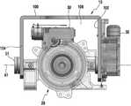
도 1은 본 발명의 다양한 실시예에 따른 3축 카메라 짐벌의 전면을 나타내는 사시도이다. 도 2는 본 발명의 다양한 실시예에 따른 3축 카메라 짐벌의 후면을 나타내는 사시도이다.1 is a perspective view illustrating a front surface of a three-axis camera gimbals according to various embodiments of the present invention. 2 is a perspective view showing a rear surface of a three-axis camera gimbals according to various embodiments of the present invention.
도 1, 도 2를 참조하면, 다양한 실시예에 따른 3축 카메라 짐벌(3-axis camera gimbal)(이하 짐벌이라 기재하기로 한다)은 드론과 같은 무인 비행체에 장착하여, 카메라 렌즈의 수평 자세를 유지하게 하는 기구물일 수 있다. 특히, 다양한 실시예에 따른 짐벌은 초소형 사이즈이면서 경량으로 구성되어서, 소형 사이즈의 드론에 실장될 수 있는 짐벌일 수 있다. 또한, 다양한 실시예에 따른 짐벌은 카메라와 같은 촬상 장치를 3축을 따라 카메라의 수평 유지를 정밀하게 제어할 수 있다.Referring to FIGS. 1 and 2, a 3-axis camera gimbal (hereinafter referred to as a gimbals) according to various embodiments is mounted on a unmanned air vehicle such as a drone, It can be an instrument to keep it. In particular, the gimbals according to various embodiments may be compact and lightweight, and may be burdened to be mounted on a small sized dron. In addition, the gimbals according to various embodiments can precisely control the horizontal retention of the camera along the three axes of an imaging device such as a camera.
다양한 실시예에 따른 짐벌은 복수 개의 지지체(10,12)와, 렌즈 배럴(20)(lens barrel), 롤링 구동부(30)(rolling driving unit), 피칭 구동부(32)(pitching driving unit) 및 요잉 구동부(34)(yawing driving unit)를 포함할 수 있다. 언급된 구동부(driving unit)는 구동 장치, 구동 모듈, 구동 부품 등으로 다르게 지칭할 수 있다. 언급된 짐벌은 수평 안정화 장치, 스태빌라이저 등으로 다르게 지칭할 수 있다.The gimbals according to various embodiments include a plurality of
다양한 실시예에 따른 복수 개의 지지체(10,12)는 상기 구동부들(30,32,34)을 안전하게 실장하여 동작가능하게 하고, 드론(drone)과 같은 무인 비행체에 장착가능하게 할 수 있다.The plurality of
다양한 실시예에 따른 지지체는 제1지지체(10)(supporting body)와, 제2지지체(12)를 포함할 수 있다. 다양한 실시예에 따른 제1지지체(10)는 롤링 구동부(30)(렌즈 배럴에 장착되고, 렌즈 배럴은 제1지지체에 장착됨)와 피칭 구동부(32)가 장착되는 장착 부재로서, 절곡진 형상으로 구성될 수 있다. 제1지지체(10)는 제1프레임(100)과, 상기 제1프레임(100) 양단에서 각각 직각방향으로 연장된 제2,3프레임(102,104)을 포함할 수 있다. 제1프레임(100)은 수평한 상태이고, 제2,3프레임(102,103)은 수직 상태로 배치될 수 있다.The support according to various embodiments may include a
다양한 실시예에 따른 제1지지체(10)의 단면은 'ㄷ'형상으로 구성될 수 있다. 제1,2,3프레임(100,102,104)에 의해 마련된 공간에 렌즈 배럴(20)이 실장되고, 제2프레임(102)에 피칭 구동부(32)가 실장될 수 있다.The cross section of the
다양한 실시예에 따른 제2지지체(12)는 요잉 구동부(34)가 장착되는 장착 부재로서, 대략적으로 플레이트 형상으로 구성될 수 있다. 제2지지체(12)는 제1지지체(10)에 회전가능하게 결합될 수 있다. 제2지지체(12)는 4군데 모서리 부근에 체결부(120)를 배치하여, 예를 들어 드론과 같은 무인 비행체에 장착가능하게 한다. 또한, 제2지지체(12)는 메인 인쇄회로기판(122)이 장착되는 부재일 수 있다. 제2지지체(12)는 복수 개의 부품들이 장착되어서, 마운트 프레임이라 지칭할 수 있다.The
참조번호 B는 베어링을 지칭하고, S1은 피칭 샤프트를 지칭한다.Reference numeral B designates a bearing, and S1 designates a pitching shaft.
도 3은 본 발명의 다양한 실시예에 따른 롤링 구동부, 피칭 구동부 및 렌즈 배럴의 장착 상태를 나타내는 사시도이다. 도 4는 도 3의 정면도이다.3 is a perspective view illustrating a mounting state of a rolling driver, a pitching driver, and a lens barrel according to various embodiments of the present invention. 4 is a front view of Fig.
도 3, 도 4를 참조하면, 다양한 실시예에 따른 렌즈 배럴(20)은 제1지지체(10)에 장착되는데, 특히 제1,2,3프레임(100,102,104) 사이의 공간(106)에 제1축(A1)을 중심으로 회전가능하게 결합될 수 있다. 렌즈 배럴(20)은 피칭 샤프트(S1)에 의해 제2,3프레임(102,104) 사이에 각각 결합될 수 있다. 피칭 샤프트(S1)는 제1축(A1)(first axis)을 제공할 수 있다.Referring to FIGS. 3 and 4, the
다양한 실시예에 따른 롤링 구동부(30)는 렌즈 배럴(20)의 제1위치에 장착되어, 렌즈 배럴(20)에 수용된 렌즈군(232;도 10)을 제2축(A2)을 중심으로 회전하는 구동힘을 제공할 수 있다. 롤링 구동부(30)는 렌즈 배럴(20)의 외주면에 고정될 수 있다. 예컨대, 롤링 구동부(30)는 제1프레임(100)과 대면하는 렌즈 배럴(20) 외주면에 장착될 수 있다.The rolling
다양한 실시예에 따른 피칭 구동부(32)는 제2프레임(102)에 장착될 수 있다. 피칭 구동부(32)는 제2프레임(102) 외면에 길이 방향을 따라서 렌즈 배럴(20)의 적어도 일부와 연동가능하게 배치될 수 있다.The pitching
도 5a는 본 발명의 다양한 실시예에 따른 요잉 구동부가 장착된 제2지지체를 위에서 본 상태를 나타내는 사시도이다. 도 5b 본 발명의 다양한 실시예에 따른 요잉 구동부가 장착된 제2지지체를 아래에서 본 상태를 나타내는 사시도이다.FIG. 5A is a perspective view showing a state in which the second support having the yaw driving part mounted thereon is viewed from above, according to various embodiments of the present invention. FIG. FIG. 5B is a perspective view showing a state in which a second support body equipped with a yawing drive unit according to various embodiments of the present invention is viewed from below. FIG.
도 5a, 도 5b를 참조하면, 다양한 실시예에 따른 요잉 구동부(34)는 제2지지체(12) 하면(12a) 둘레를 따라서 평행하게 실장될 수 있다. 요잉 구동부(340는 제2지지체(12)와 제1프레임(100;도 1, 도 2) 사이에 배치되어서, 제1지지체(10)의 회전 힘을 제공할 수 있다.5A and 5B, the
다시, 도 1, 도 2를 참조하면, 다양한 실시예에 따른 짐벌은 렌즈 배럴(20)의 3축 회전을 제공할 수 있다. 렌즈 배럴(20)은 제1축(A1)을 중심으로 피칭 동작이 가능하고, 제2축(A2)을 중심으로 롤링 동작이 가능하고, 제3축(A3)을 중심으로 요잉 동작이 가능할 수 있다. 제2축(A2)이 렌즈 배럴(20)에 실장된 렌즈부의 광학축(optical axis)이 될 수 있다.Referring again to Figures 1 and 2, the gimbals according to various embodiments may provide three-axis rotation of the
제1축(A1)은 제2축(A2)과 서로 수직방향으로 향하고, 제2축(A2)은 제3축(A3)과 수직방향으로 향하고, 제3축(A3)은 제1,2축(A1,A2)과 수직방향으로 향할 수 있다. 또한, 제1축(A1)은 제2축(A2)과 서로 직교할 수 있고, 제2축(A2)은 제3축(A3)과 서로 직교할 수 있고, 제3축(A3)은 제1,2축(A1,A2)과 서로 직교할 수 있다.The first axis Al is perpendicular to the second axis A2 and the second axis A2 is perpendicular to the third axis A3 and the third axis A3 is perpendicular to the first and second axes A2, And can be oriented perpendicular to the axes A1 and A2. The first axis A1 may be orthogonal to the second axis A2 and the second axis A2 may be perpendicular to the third axis A3 and the third axis A3 may be perpendicular to the second axis A2. And can be orthogonal to the 1,2 axis (A1, A2).
다양한 실시예에 따른 제2축(A2)은 렌즈 배럴(20)에 수용된 렌즈군의 광학축으로서, 렌즈군 중심 전후방을 관통하는 방향일 수 있다. 다양한 실시예에 따른 제1축(A1)은 렌즈 배럴(20) 회전축으로서, 제1프레임(100)과 평행하며, 제2,3프레임(102,104)을 횡단하는 회전축일 수 있다. 제3축(A3)은 제1지지체(10)의 회전축으로서, 제1프레임(100) 중심과, 제2지지체(12) 중심을 상하 방향으로 관통하는 방향일 수 있다.The second axis A2 according to various embodiments may be an optical axis of the lens group accommodated in the
다양한 실시예에 따른 렌즈 배럴(20)은 초기 위치를 파악하기 위한 초기 위치 감지부를 더 구비할 수 있다. 다양한 실시예에 따른 초기위치 감지부는 렌즈 배럴(20)에 구비된 광센서(40)와, 제2프레임(102)에서 연장되어서, 상기 광센서(40)를 동작시키는 액츄에이터(42)를 포함할 수 있다. 광센서(40)는 렌즈 배럴(20)에 일체형으로 구성되어서, 상기 렌즈 배럴(20)과 함께 제1축(A1)을 중심으로 회전동작을 할 수 있다. 액츄에이터(42)는 광센서(40)의 회전에 따라 수광부와 발광부 사이에 존재하거나, 수광부와 발광부 사이를 벗어날 수 있다. 광센서(40)는 렌즈 배럴(20)의 초기 위치를 파악하여, 감지된 신호를 제어부에 출력할 수 있다.The
최초 전원 공급 시, 액츄에이터(42)가 수광부를 가리고 있다면, 수광부를 가리지 않는 방향으로 회전하여 초기 위치를 찾고, 액츄에이터(42)가 수광부를 가리고 있지 않다면, 수광부가 가려지는 방향으로 회전하여 초기 위치를 검출할 수 있다.If the
도 6a는 본 발명의 다양한 실시예에 따른 3축 카메라 짐벌에 채용된 롤링 구동부의 구성을 나타내는 사시도이다. 도 6b는 본 발명의 다양한 실시예에 따른 렌즈 배럴 외주면에 장착된 롤링 구동부의 연동 상태를 나타내는 사시도이다.6A is a perspective view showing a configuration of a rolling driver employed in a 3-axis camera gimbal according to various embodiments of the present invention. 6B is a perspective view illustrating an interlocked state of a rolling driving unit mounted on an outer circumferential surface of a lens barrel according to various embodiments of the present invention.
도 6a, 도 6b를 참조하면, 다양한 실시예에 따른 짐벌에 채용된 롤링 구동부(30)는 렌즈 배럴에 배치된 이미지 센서와, 렌즈군(lens group)을 제2축(A2)을 중심으로 롤링 동작을 할 수 있는 구동힘을 제공하는 동력부일 수 있다. 다양한 실시예에 따른 롤링 구동부(30)는 구동 모터(301)와, 기어 어레이(gear array)를 포함할 수 있다. 구동 모터(301)는 정밀 제어가 가능한 모터일 수 있다.6A and 6B, the rolling driving
다양한 실시예에 따른 기어 어레이는 구동 모터(301) 축과 연결된 제1기어(302)와, 상기 제1기어(302)와 맞물린 제2기어(303)와, 상기 제2기어(303)와 맞물린 제3기어(310)를 포함할 수 있다. 제1기어(302)와 제2기어(303)는 웜 기어로 구성될 수 있다. 제3기어(310)는 렌즈 배럴에 장착된 회전 부재일 수 있다. 이하 제3기어를 회전 부재라고 지칭하기로 한다.The gear array according to various embodiments includes a
다양한 실시예에 따른 회전 부재(310)는 외주면 소정 거리에 기어 이빨(3100)이 형성되어 상기 웜 기어(303)와 맞물리게 배치될 수 있다. 구동 모터(301)가 동작하면, 제1기어(302)가 회전하고, 상기 제1기어(302)와 직교하게 배치된 제2기어(303,304)가 회전하고, 상기 제2기어(304)는 회전 부재(310)에 동력을 전달할 수 있다. 참조부호 305는 구동 모터에서 인출된 FPCB이고, 참조부호 306은 설치 브라켓일 수 있다.The
도 7은 본 발명의 다양한 실시예에 따른 3축 카메라 짐벌에 채용된 피칭 구동부의 구성을 나타내는 사시도이다.7 is a perspective view showing a configuration of a pitching driver employed in a 3-axis camera gimbal according to various embodiments of the present invention.
도 7을 참조하면, 다양한 실시예에 따른 짐벌에 채용된 피칭 구동부(32)는 제2프레임(102) 길이 방향을 따라서 직립되게 장착될 수 있다. 피칭 구동부(32)는 구동 모터(321)와, 기어 어레이를 포함할 수 있다. 구동 모터(321)는 정밀 제어가 가능한 구동 장치일 수 있다. 기어 어레이는 구동 모터(321) 축과 동축을 배치된 제1기어(322)와, 제1기어(322)와 수직방향으로 배치되어 맞물린 제2기어(323)를 포함할 수 있다. 제1,2기어(322,323)를 공지의 웜 기어라 정의할 수 있다. 제2기어(323)는 다른 제2기어(324)에 맞물리고, 맞물린 다른 제2기어(324)는 렌즈 배럴 회전축과 일체형인 제3기어(325)에 맞물리게 배치될 수 있다. 구동 모터(321)가 구동되면, 회전 동력은 제1,2기어(322,323,324)를 지나 제3기어(325)에 전달되어, 렌즈 배럴을 제1축(A1)을 중심으로 피칭 동작을 할 수 있다. 구동 모터(321)는 미도시된 제어부에 의해 회전 정도가 제어될 수 있다.Referring to FIG. 7, the pitching
도 8은 본 발명의 다양한 실시예에 따른 3축 카메라 짐벌에 채용된 요잉 구동부의 구성을 나타내는 사시도이다.FIG. 8 is a perspective view showing a structure of a yaw driving part employed in a 3-axis camera gimbal according to various embodiments of the present invention. FIG.
도 8을 참조하면, 다양한 실시예에 따른 짐벌에 채용된 요잉 구동부(34)는 제2지지체 하면에 대략적으로 평행하게 장착될 수 있다. 다양한 실시예에 따른 요잉 구동부(34)는 구동 모터(341)와, 기어 어레이를 포함할 수 있다. 구동 모터(341)는 정밀 제어가 가능한 구동 장치일 수 있다. 기어 어레이는 구동 모터(341) 축과 동축으로 배치된 제1기어(342)와, 제1기어(342)와 수직 방향으로 배치되어 맞물린 제2기어(343)를 포함할 수 있다. 제1,2기어(342,343)를 공지의 웜 기어(worm gear)라 정의할 수 있다. 제2기어는 복수 개의 기어 배열(344,345)을 포함할 수 있다. 마지막 제2기어(346)는 요잉 샤프트 회전축과 일체형인 제3기어(347)에 맞물리게 배치될 수 있다. 구동 모터(341)가 구동되면, 회전 동력은 제1,2기어(342,343,344,345,346)를 지나 제3기어(347)에 전달되어, 제3축을 중심으로 렌즈 배럴의 피칭 동작을 할 수 있다. 구동 모터는 미도시된 제어부에 의해 회전 정도가 제어될 수 있다.Referring to FIG. 8, the
도 9는 본 발명의 다양한 실시예에 따른 렌즈 배럴에 구성된 롤링부의 장착 상태를 나타내는 사시도이다. 도 10은 본 발명의 다양한 실시예에 따른 렌즈 배럴의 구성을 단면으로 나타내는 사시도이다.9 is a perspective view showing a mounting state of a rolling part constituted in a lens barrel according to various embodiments of the present invention. 10 is a perspective view showing, in cross section, the configuration of a lens barrel according to various embodiments of the present invention.
도 9, 도 10을 참조하면, 다양한 실시예에 따른 렌즈 배럴(20)은 하우징(210)과, 이미지 센서(230)와, 렌즈군(232)과, 회전 부재(220)와, 롤링부(240,250)를 포함할 수 있다. 렌즈 배럴(20)은 카메라 기능을 하는 촬상 장치로서, 광축이 존재할 수 있다.9 and 10, the
다양한 실시예에 따른 하우징(210)은 이미지 센서(230)와, 렌즈군(232)과, 회전 부재(220)와, 롤링부(240,250)를 수용할 수 있는 대략 원통형 하우징일 수 있다. 하우징 전방면은 렌즈가 노출되고, 후방면은 백 커버가 결합될 수 있다.The
다양한 실시예에 따른 이미지 센서(230)는 광신호를 전기신호로 변화하여 이미지를 생성하기 위한 촬상 소자로서, 렌즈군(232)과 이격된 상태로 대면하게 배치될 수 있다.The
다양한 실시예에 따른 렌즈군(232)은 광학축을 따라 배치된 복수 개의 렌즈들을 포함할 수 있다.The
다양한 실시예에 따른 회전 부재(220)는 하우징(210) 내에서 롤링 구동부에 의해 제2축을 중심으로 회전하는 부재로서, 이미지 센서(230)와 렌즈군(232)이 장착되어 고정될 수 있다. 이미지 센서(230)와 렌즈군(232)은 회전 부재(220)에 고정되어, 회전 부재(220)와 함께 회전할 수 있다.The
다양한 실시예에 따른 회전 부재(220)는 제1방향을 향하는 제1면과, 제1면과 반대 방향인 제2방향을 향하는 제2면과, 제1,2면에 의해 마련된 측면을 가지는 형상일 수 있다. 제1방향은 전방일 수 있고, 제2방향은 후방일 수 있다. 회전 부재(220)는 롤링부가 구르는 트랙이나 레일을 포함할 수 있다.The
다양한 실시예에 따른 롤링부(240,250)는 하우징(210)과 회전 부재(220) 사이에 장착되어서, 회전 부재(220)의 회전 동작 시에 마찰을 최소화하기 위해 설치될 수 있다. 롤링부는 회전 부재(220) 제1면에 배치되는 제1롤링부(240)와, 제2면에 배치되는 제2롤링부(250)를 포함할 수 있다. 회전 부재(220) 제1,2면에 각각 제1,2롤링부(240,250)가 배치되어서, 마찰을 최소화할 수 있다. 제1롤링부(240)는 적어도 3개의 제1롤러들을 포함할 수 있다. 제2롤링부(250)는 적어도 3개의 제2롤러들을 포함할 수 있다. 제1롤러들은 회전 부재(220) 제1면에 등 간격으로 배치되어 제1면 상에서 구름 동작을 할 수 있다. 제2롤러들은 회전 부재(220) 제2면에 등 간격으로 배치되어 제2면 상에서 구름 동작을 할 수 있다.The rolling
도 11은 본 발명의 다양한 실시예에 따른 제1지지체의 결합 상태를 나타내는 사시도이다. 도 12는 본 발명의 다양한 실시예에 따른 제1지지체의 결합 상태를 나타내는 단면도이다.11 is a perspective view showing a state of engagement of a first support according to various embodiments of the present invention. 12 is a cross-sectional view showing a state of engagement of a first support according to various embodiments of the present invention.
도 11, 도 12를 참조하면, 다양한 실시예에 따른 제1지지체(10)의 결합 구조에 대해서 설명하면 다음과 같다.11 and 12, a coupling structure of the
다양한 실시예에 따른 상기 결합 구조는 제1프레임(100)과, 고정 프레임(125)과, 회전 프레임(124)과, 기어(347) 및 요잉 샤프트(S1) 간의 결합 구성 포함할 수 있다.The coupling structure according to various embodiments may include a coupling structure between the
다양한 실시예에 따른 결합 구조는 제3축(A3)을 제공하는 요잉 샤트트(S2)(yawing shaft)를 기준으로, 회전 프레임(124)과 요잉 샤프트(S2) 사이에 베어링(B1)이 배치될 수 있다. 또한, 기어(347)가 요잉 샤프트(S2)에 압입되되, 상단 베어링과 하단 베어링 사이에 배치될 수 있다.The coupling structure according to various embodiments may include a bearing B1 disposed between the
다양한 실시예에 따른 고정 프레임(125)은 제1프레임(100) 상면 중앙에 체결구, 예컨대 나사를 이용하여 일체형으로 체결될 수 있다. 또한, 고정 프레임(125)은 기어(347)와 일체형으로 고정될 수 있다. 기어(347)와, 고정 프레임(125) 및 제1프레임(100)은 함께 제3축(A3)을 중심으로 회전할 수 있다. 기어(347)는 도 8에 도시된 기어(347)과 동일한 기어일 수 있다.The fixed
요잉 구동부의 구동 모터가 동작하여 기어(347)이 회전하면, 상기 고정 프레임(125)과 제1프레임(100)은 함께 회전동작을 수행할 수 있다.When the driving motor of the yawing driving unit operates to rotate the
본 발명의 다양한 실시예에 따른 3축 카메라 짐벌은 제1지지체; 렌즈군을 포함하되, 상기 제1지지체에 제1축을 중심으로 회전가능하게 결합된 렌즈 배럴; 상기 렌즈 배럴 제1위치에 장착되어, 상기 렌즈군을 제1축과 수직인 제2축을 중심으로 회전하는 힘을 제공하는 롤링 구동부; 상기 제1지지체에 장착되어, 상기 렌즈 베럴을 상기 제1축을 중심으로 회전하는 힘을 제공하는 피칭 구동부; 상기 제1지지체에 상기 제1,2축과 각각 수직인 제3축을 중심으로 회전가능하게 결합된 제2지지체; 및 상기 제2지지체에 장착되어 상기 제1지지체를 상기 제3축을 중심으로 회전하게 하는 요잉 구동부를 포함할 수 있다.A three-axis camera gimbals according to various embodiments of the present invention may include a first support; A lens barrel including a lens group, the lens barrel being rotatably coupled to the first support body about a first axis; A rolling driver mounted on the lens barrel at a first position to provide a force to rotate the lens group about a second axis perpendicular to the first axis; A pitching driver mounted on the first support to provide a force to rotate the lens barrel about the first axis; A second support rotatably coupled to the first support body about a third axis perpendicular to the first and second axes; And a yaw driving unit mounted on the second support body and rotating the first support body about the third axis.
본 발명의 다양한 실시예에 따른 제2지지체에 복수 개의 체결부를 사용하여 무인 비행체에 장착될 수 있다.The second support according to various embodiments of the present invention may be mounted on the unmanned aerial vehicle using a plurality of fastening portions.
본 발명의 다양한 실시예에 따른 제1지지체는 단면이'ㄷ'형인 절곡진 형상으로, 제1프레임; 및 상기 제1프레임 양단에서 각각 직각방향으로 연장된 제2,3프레임을 포함할 수 있다.The first support according to various embodiments of the present invention has a curved shape with a cross section of 'C' shape, And second and third frames extending at right angles to each other at both ends of the first frame.
본 발명의 다양한 실시예에 따른 제2지지체는 상기 제1프레임 상에 수평하게 배치되되, 상기 제3축을 중심으로 회전가능하게 장착되는 마운트 프레임을 포함할 수 있다.A second support according to various embodiments of the present invention may include a mount frame disposed horizontally on the first frame and rotatably mounted about the third axis.
본 발명의 다양한 실시예에 따른 제1축은 상기 제1프레임과 평행하면서, 상기 제2,3프레임 사이를 횡단하는 방향으로 향하고, 상기 제3축은 상기 제1프레임의 중심을 상하로 향하며, 상기 제2축은 렌즈 베럴 광축 중심을 관통하는 방향으로 향할 수 있다.The first axis is parallel to the first frame and is directed in a direction traversing between the second and third frames, the third axis is oriented up and down the center of the first frame, The two axes can be oriented in a direction passing through the center of the optical axis of the lens barrel.
본 발명의 다양한 실시예에 따른 렌즈 배럴은 하우징; 및 하우징 내에 회전가능하게 배치되는 회전 부재를 포함할 수 있다.A lens barrel according to various embodiments of the present invention includes a housing; And a rotatable member rotatably disposed within the housing.
본 발명의 다양한 실시예에 따른 렌즈 배럴은 상기 회전 부재에 장착되는 이미지 센서; 및 상기 이미지 센서와 대면하는 렌즈군을 포함하되, 상기 이미지 센서와 렌즈군은 제1축을 중심으로 회전 부재 상에서 함께 회전할 수 있다.A lens barrel according to various embodiments of the present invention includes an image sensor mounted on the rotating member; And a lens group facing the image sensor, wherein the image sensor and the lens group can rotate together on a rotating member about a first axis.
본 발명의 다양한 실시예에 따른 렌즈 배럴은 적어도 하나 이상의 롤링부를 포함할 수 있다.The lens barrel according to various embodiments of the present invention may include at least one or more rolling parts.
본 발명의 다양한 실시예에 따른 롤링부는 상기 회전부재에 제1면에 배치된 적어도 3개의 제1롤러들을 포함하는 제1롤링부; 및 상기 회전부재 제1면과 반대방향의 제2면에 배치된 적어도 3개의 제2롤러들을 포함하는 제2롤링부를 포함할 수 있다.According to various embodiments of the present invention, the rolling part includes a first rolling part including at least three first rollers disposed on the first surface of the rotating member; And a second rolling part including at least three second rollers disposed on a second surface opposite to the first surface of the rotating member.
본 발명의 다양한 실시예에 따른 각각의 롤링 구동부, 피칭 구동부 및 요잉 구동부는 복수개의 구동 모터 및 각각의 구동 모터에 맞물린 복수 개의 기어 어레이를 포함하되, 상기 각각의 기어 어레이는 형상이 같은 웜 기어를 포함할 수 있다.Each of the rolling, pitching and yawing motors according to various embodiments of the present invention includes a plurality of driving motors and a plurality of gear arrays meshed with the respective driving motors, .
본 발명의 다양한 실시예에 따른 제2지지체는 메인 인쇄회로기판이 고정되되, 상기 이미지 센서에서 메인 인쇄회로기판 사이는 연성회로기판을 이용하여 전기적으로 연결되며, 상기 연성회로기판은 변곡점의 위치가 가변되게 배치될 수 있다.The second support according to various embodiments of the present invention includes a main printed circuit board to which the main printed circuit board is fixed, the main printed circuit board being electrically connected to the main printed circuit board using a flexible circuit board, And can be arranged to be variable.
본 발명의 다양한 실시예에 따른 렌즈 배럴은 초기 위치 감지부를 더 구비할 수 있다.The lens barrel according to various embodiments of the present invention may further include an initial position sensing unit.
본 발명의 다양한 실시예에 따른 초기 위치 감지부는 상기 렌즈 배럴에 배치된 센서; 및 상기 제2프레임에 형성되어, 상기 센서를 동작시키는 액츄에이터를 포함할 수 있다.An initial position sensing unit according to various embodiments of the present invention includes a sensor disposed in the lens barrel; And an actuator formed on the second frame to operate the sensor.
본 발명의 다양한 실시예에 따른 센서는 렌즈 배럴 하단 외주영역에 배치되고, 상기 액츄에이터는 제2프레임 단부에서 센서 방향으로 연장될 수 있다.The sensor according to various embodiments of the present invention may be disposed in the outer peripheral region of the lower portion of the lens barrel, and the actuator may extend in the sensor direction at the second frame end.
본 발명의 다양한 실시예에 따른 3축 카메라 짐벌은 적어도 하나 이상의 지지체; 및 상기 지지체에 장착되어, 3개의 회전축을 중심으로 각각 회전가능하게 결합된 렌즈 배럴을 포함하되, 상기 렌즈 배럴은 회전 부재; 및 상기 회전 부재의 표면에서 광축을 중심으로 회전하는 롤링부를 포함하며, 상기 롤링부는 상기 회전 부재에 제1면에 배치된 제1롤러들을 포함하는 제1롤링부; 및 상기 회전부재 제1면과 반대방향의 제2면에 배치된 제2롤러들을 포함하는 제2롤링부를 포함할 수 있다.The three-axis camera gimbals according to various embodiments of the present invention include at least one support; And a lens barrel mounted on the support and rotatably coupled to each of the three rotation shafts, the lens barrel including: a rotary member; And a rolling unit rotating around an optical axis at a surface of the rotating member, wherein the rolling unit includes a first rolling unit including first rollers disposed on a first surface of the rotating member; And a second rolling part including second rollers disposed on a second surface opposite to the first surface of the rotary member.
본 발명의 다양한 실시예에 따른 각각의 제1,2롤링부는 적어도 3개의 롤러들로 각각 구성될 수 있다.Each of the first and second rolling parts according to various embodiments of the present invention may be composed of at least three rollers.
본 발명의 다양한 실시예에 따른 3축 카메라 짐벌은 지지체; 및 상기 지지체에 장착되어, 3개의 회전축을 중심으로 각각 회전가능하게 결합된 렌즈 배럴을 포함하고, 상기 렌즈 배럴은 회전 부재; 및 상기 회전 부재 사이에 배치되는 롤링부를 포함하며, 상기 렌즈 배럴 외주면에 롤링 구동부가 결합되되, 상기 롤링 구동부는 회전 부재와 맞물리게 장착될 수 있다.A three-axis camera gimbals according to various embodiments of the present invention include a support; And a lens barrel attached to the support and rotatably coupled to each of the three rotation shafts, the lens barrel comprising: a rotary member; And a rolling unit disposed between the rotating members, wherein a rolling driving unit is coupled to an outer circumferential surface of the lens barrel, and the rolling driving unit can be mounted to be engaged with the rotating member.
본 발명의 다양한 실시예에 따른 롤링부는 상기 회전 부재에 제1면에 배치된 제1롤러들을 포함하는 제1롤링부; 및 상기 회전부재 제1면과 반대방향의 제2면에 배치된 제2롤러들을 포함하는 제2롤링부를 포함할 수 있다.According to various embodiments of the present invention, the rolling portion includes a first rolling portion including first rollers disposed on the first surface of the rotating member; And a second rolling part including second rollers disposed on a second surface opposite to the first surface of the rotary member.
본 발명의 다양한 실시예에 따른 회전 부재는 이미지 센서가 배치되어 함께 회전할 수 있다.The rotating member according to various embodiments of the present invention may be arranged and rotated together with the image sensor.
본 문서에서 사용된 용어 "모듈"은 예를 들면, 하드웨어, 소프트웨어 또는 펌웨어 (firmware) 중 하나 또는 둘 이상의 조합을 포함하는 단위 (unit)를 의미할 수 있다. "모듈"은, 예를 들면, 유닛 (unit), 로직 (logic), 논리 블록 (logical block), 부품 (component), 또는 회로 (circuit) 등의 용어와 바꾸어 사용 (interchangeably use)될 수 있다. "모듈"은, 일체로 구성된 부품의 최소 단위 또는 그 일부가 될 수 있다. "모듈"은 하나 또는 그 이상의 기능을 수행하는 최소 단위 또는 그 일부가 될 수도 있다. 은 기계적으로 또는 전자적으로 구현될 수 있다. 예를 들면, "모듈"은, 알려졌거나 앞으로 개발될, 어떤 동작들을 수행하는 ASIC(application-specific integrated circuit) 칩, FPGAs(field-programmable gate arrays) 또는 프로그램 가능 논리 장치(programmable-logic device) 중 적어도 하나를 포함할 수 있다.As used in this document, the term "module" may refer to a unit comprising, for example, one or more combinations of hardware, software or firmware. A "module" may be interchangeably used with terms such as, for example, unit, logic, logical block, component, or circuit. A "module" may be a minimum unit or a portion of an integrally constructed component. A "module" may be a minimum unit or a portion thereof that performs one or more functions. May be implemented mechanically or electronically. For example, a "module" may be an application-specific integrated circuit (ASIC) chip, field-programmable gate arrays (FPGAs) or programmable-logic devices And may include at least one.
다양한 실시예에 따르면, 본 개시에 따른 장치(예: 모듈들 또는 그 기능들) 또는 방법(예: 동작들)의 적어도 일부는, 예컨대, 프로그래밍 모듈의 형태로 컴퓨터로 읽을 수 있는 저장매체(computer-readable storage media)에 저장된 명령어로 구현될 수 있다. 상기 명령어는, 하나 이상의 프로세서 (예: 상기 프로세서 210)에 의해 실행될 경우, 상기 하나 이상의 프로세서가 상기 명령어에 해당하는 기능을 수행할 수 있다. 컴퓨터로 읽을 수 있는 저장매체는, 예를 들면, 상기 메모리가 될 수 있다. 상기 프로그래밍 모듈의 적어도 일부는, 예를 들면, 프로세서에 의해 구현(implement)(예:실행)될 수 있다. 상기 프로그래밍 모듈의 적어도 일부는 하나 이상의 기능을 수행하기 위한, 예를 들면, 모듈, 프로그램, 루틴, 명령어 세트(sets of instructions) 또는 프로세스 등을 포함할 수 있다.According to various embodiments, at least some of the devices (e.g., modules or functions thereof) or methods (e.g., operations) according to the present disclosure may be stored in a computer readable storage medium -readable storage media). The instructions, when executed by one or more processors (e.g., the processor 210), may cause the one or more processors to perform functions corresponding to the instructions. The computer readable storage medium may be, for example, the memory. At least some of the programming modules may be implemented (e.g., executed) by, for example, a processor. At least some of the programming modules may include, for example, modules, programs, routines, sets of instructions or processes, etc. to perform one or more functions.
상기 컴퓨터로 판독 가능한 기록 매체에는 하드디스크, 플로피디스크 및 자기 테이프와 같은 마그네틱 매체(Magnetic Media)와, CD-ROM(Compact Disc Read Only Memory), DVD(Digital Versatile Disc)와 같은 광기록 매체(Optical Media)와, 플롭티컬 디스크(Floptical Disk)와 같은 자기-광 매체(Magneto-Optical Media)와, 그리고 ROM(Read Only Memory), RAM(Random Access Memory), 플래시 메모리 등과 같은 프로그램 명령(예: 프로그래밍 모듈)을 저장하고 수행하도록 특별히 구성된 하드웨어 장치가 포함될 수 있다. 또한, 프로그램 명령에는 컴파일러에 의해 만들어지는 것과 같은 기계어 코드뿐만 아니라 인터프리터 등을 사용해서 컴퓨터에 의해서 실행될 수 있는 고급 언어 코드를 포함할 수 있다. 상술한 하드웨어 장치는 본 개시의 동작을 수행하기 위해 하나 이상의 소프트웨어 모듈로서 작동하도록 구성될 수 있으며, 그 역도 마찬가지다.The computer-readable recording medium includes a magnetic medium such as a hard disk, a floppy disk and a magnetic tape, an optical recording medium such as a CD-ROM (Compact Disc Read Only Memory), a DVD (Digital Versatile Disc) A magneto-optical medium such as a floppy disk, and a program command such as a read only memory (ROM), a random access memory (RAM), a flash memory, Module) that is configured to store and perform the functions described herein. The program instructions may also include machine language code such as those generated by a compiler, as well as high-level language code that may be executed by a computer using an interpreter or the like. The hardware devices described above may be configured to operate as one or more software modules to perform the operations of this disclosure, and vice versa.
본 개시에 따른 모듈 또는 프로그래밍 모듈은 전술한 구성요소들 중 적어도 하나 이상을 포함하거나, 일부가 생략되거나, 또는 추가적인 다른 구성요소를 더 포함할 수 있다. 본 개시에 따른 모듈, 프로그래밍 모듈 또는 다른 구성요소에 의해 수행되는 동작들은 순차적, 병렬적, 반복적 또는 휴리스틱(heuristic)한 방법으로 실행될 수 있다. 또한, 일부 동작은 다른 순서로 실행되거나, 생략되거나, 또는 다른 동작이 추가될 수 있다.A module or programming module according to the present disclosure may include at least one or more of the elements described above, some of which may be omitted, or may further include other additional elements. Operations performed by modules, programming modules, or other components in accordance with the present disclosure may be performed in a sequential, parallel, iterative, or heuristic manner. Also, some operations may be performed in a different order, omitted, or other operations may be added.
그리고, 본 명세서와 도면에 개시된 본 개시의 다양한 실시예들은 본 개시의 기술 내용을 쉽게 설명하고 본 개시의 이해를 돕기 위해 특정 예를 제시한 것일 뿐이며, 본 개시의 범위를 한정하고자 하는 것은 아니다. 따라서 본 개시의 범위는 여기에 개시된 실시 예들 이외에도 본 개시의 기술적 사상을 바탕으로 도출되는 모든 변경 또는 변형된 형태가 본 개시의 범위에 포함되는 것으로 해석되어야 한다.It is to be understood that the various embodiments of the present disclosure disclosed in this specification and the drawings are only illustrative of specific examples in order to facilitate describing the subject matter of the disclosure and to facilitate understanding of the disclosure, and are not intended to limit the scope of the disclosure. Accordingly, the scope of the present disclosure should be construed as being included within the scope of the present disclosure in addition to the embodiments disclosed herein, all changes or modifications derived from the technical idea of the present disclosure.
Claims (19)
Translated fromKorean제1지지체;
렌즈군을 포함하되, 상기 제1지지체에 제1축을 중심으로 회전가능하게 결합된 렌즈 배럴;
상기 렌즈 배럴 제1위치에 장착되어, 상기 렌즈군을 제1축과 수직인 제2축을 중심으로 회전하는 힘을 제공하는 롤링 구동부;
상기 제1지지체에 장착되어, 상기 렌즈 베럴을 상기 제1축을 중심으로 회전하는 힘을 제공하는 피칭 구동부;
상기 제1지지체에 상기 제1,2축과 각각 수직인 제3축을 중심으로 회전가능하게 결합된 제2지지체; 및
상기 제2지지체에 장착되어 상기 제1지지체를 상기 제3축을 중심으로 회전하게 하는 요잉 구동부를 포함하는 짐벌.For a three-axis gimbal,
A first support;
A lens barrel including a lens group, the lens barrel being rotatably coupled to the first support body about a first axis;
A rolling driver mounted on the lens barrel at a first position to provide a force to rotate the lens group about a second axis perpendicular to the first axis;
A pitching driver mounted on the first support to provide a force to rotate the lens barrel about the first axis;
A second support rotatably coupled to the first support body about a third axis perpendicular to the first and second axes; And
And a yaw driving part mounted on the second support body to rotate the first support body about the third axis.
단면이'ㄷ'형인 절곡진 형상으로,
제1프레임; 및
상기 제1프레임 양단에서 각각 직각방향으로 연장된 제2,3프레임을 포함하는 짐벌.2. The method of claim 1, wherein the first support
In the form of a curved shape having a cross section of "c"
A first frame; And
And second and third frames extending at right angles to each other at both ends of the first frame.
하우징과, 하우징 내에 회전가능하게 배치되는 회전 부재를 포함하는 짐벌.The lens barrel according to claim 1,
A gimbal comprising a housing and a rotating member rotatably disposed within the housing.
상기 회전 부재에 장착되는 이미지 센서; 및
상기 이미지 센서와 대면하는 렌즈군을 포함하되,
상기 이미지 센서와 렌즈군은 제1축을 중심으로 회전 부재 상에서 함께 회전하는 짐벌.
The lens barrel according to claim 6, wherein the lens barrel
An image sensor mounted on the rotating member; And
And a lens group facing the image sensor,
Wherein the image sensor and the lens group rotate together on a rotating member about a first axis.
상기 회전부재에 제1면에 배치된 적어도 3개의 제1롤러들을 포함하는 제1롤링부; 및
상기 회전부재 제1면과 반대방향의 제2면에 배치된 적어도 3개의 제2롤러들을 포함하는 제2롤링부를 포함하는 짐벌.9. The apparatus of claim 8, wherein the rolling section
A first rolling part including at least three first rollers disposed on the first surface of the rotating member; And
And a second rolling part including at least three second rollers disposed on a second surface opposite to the first surface of the rotating member.
The flexible printed circuit board according to claim 7, wherein the second support body is fixed to the main printed circuit board, the main printed circuit board is electrically connected to the main printed circuit board using a flexible circuit board, Gimbal placed in position.
상기 렌즈 배럴에 배치된 센서; 및
상기 제2프레임에 형성되어, 상기 센서를 동작시키는 액츄에이터를 포함하는 짐벌.13. The apparatus of claim 12, wherein the initial position sensing unit
A sensor disposed in the lens barrel; And
And an actuator formed on the second frame for operating the sensor.
적어도 하나 이상의 지지체; 및
상기 지지체에 장착되어, 3개의 회전축을 중심으로 각각 회전가능하게 결합된 렌즈 배럴을 포함하되, 상기 렌즈 배럴은
회전 부재; 및
상기 회전 부재의 표면에서 광축을 중심으로 회전하는 롤링부를 포함하며,
상기 롤링부는
상기 회전 부재에 제1면에 배치된 제1롤러들을 포함하는 제1롤링부; 및
상기 회전부재 제1면과 반대방향의 제2면에 배치된 제2롤러들을 포함하는 제2롤링부를 포함하는 짐벌.For a three-axis gimbal,
At least one support; And
And a lens barrel mounted on the support and rotatably coupled to each of the three rotation axes,
A rotary member; And
And a rolling unit that rotates about an optical axis on the surface of the rotating member,
The rolling part
A first rolling part including first rollers disposed on a first surface of the rotating member; And
And a second rolling part including second rollers disposed on a second surface opposite to the first surface of the rotating member.
지지체; 및
상기 지지체에 장착되어, 3개의 회전축을 중심으로 각각 회전가능하게 결합된 렌즈 배럴을 포함하고,
상기 렌즈 배럴은
회전 부재; 및
상기 회전 부재 사이에 배치되는 롤링부를 포함하며,
상기 렌즈 배럴 외주면에 롤링 구동부가 결합되되,
상기 롤링 구동부는 회전 부재와 맞물리게 장착되는 짐벌.For a three-axis gimbal,
A support; And
And a lens barrel attached to the support and rotatably coupled to each of the three rotation shafts,
The lens barrel
A rotary member; And
And a rolling portion disposed between the rotating members,
A rolling driving unit coupled to an outer circumferential surface of the lens barrel,
And the rolling driving unit is mounted to be engaged with the rotating member.
상기 회전 부재에 제1면에 배치된 제1롤러들을 포함하는 제1롤링부; 및
상기 회전부재 제1면과 반대방향의 제2면에 배치된 제2롤러들을 포함하는 제2롤링부를 포함하는 짐벌.18. The apparatus of claim 17, wherein the rolling section
A first rolling part including first rollers disposed on a first surface of the rotating member; And
And a second rolling part including second rollers disposed on a second surface opposite to the first surface of the rotating member.
Priority Applications (6)
| Application Number | Priority Date | Filing Date | Title |
|---|---|---|---|
| KR1020150153073AKR20170050924A (en) | 2015-11-02 | 2015-11-02 | Small gimbal for controlling 3-rotation axis |
| MYPI2018701730AMY191176A (en) | 2015-11-02 | 2016-08-19 | 3-axis adjustable small gimbal |
| PCT/KR2016/009137WO2017078254A1 (en) | 2015-11-02 | 2016-08-19 | 3-axis adjustable small gimbal |
| EP16862273.6AEP3360799B1 (en) | 2015-11-02 | 2016-08-19 | 3-axis adjustable small gimbal |
| CN201680064101.2ACN108349593B (en) | 2015-11-02 | 2016-08-19 | Three-axis adjustable small-sized pan-tilt |
| US15/773,066US10501204B2 (en) | 2015-11-02 | 2016-08-19 | 3-axis adjustable small gimbal |
Applications Claiming Priority (1)
| Application Number | Priority Date | Filing Date | Title |
|---|---|---|---|
| KR1020150153073AKR20170050924A (en) | 2015-11-02 | 2015-11-02 | Small gimbal for controlling 3-rotation axis |
Publications (1)
| Publication Number | Publication Date |
|---|---|
| KR20170050924Atrue KR20170050924A (en) | 2017-05-11 |
Family
ID=58662169
Family Applications (1)
| Application Number | Title | Priority Date | Filing Date |
|---|---|---|---|
| KR1020150153073ACeasedKR20170050924A (en) | 2015-11-02 | 2015-11-02 | Small gimbal for controlling 3-rotation axis |
Country Status (6)
| Country | Link |
|---|---|
| US (1) | US10501204B2 (en) |
| EP (1) | EP3360799B1 (en) |
| KR (1) | KR20170050924A (en) |
| CN (1) | CN108349593B (en) |
| MY (1) | MY191176A (en) |
| WO (1) | WO2017078254A1 (en) |
Cited By (9)
| Publication number | Priority date | Publication date | Assignee | Title |
|---|---|---|---|---|
| WO2018212419A1 (en)* | 2017-05-17 | 2018-11-22 | 엘지이노텍 주식회사 | Camera driving device, photography device, and flight device |
| CN109018402A (en)* | 2018-08-20 | 2018-12-18 | 陈霞 | A kind of new-type unmanned plane Multifunctional camera head bracket |
| CN109538898A (en)* | 2018-06-13 | 2019-03-29 | 幻想动力(上海)文化传播有限公司 | Support component and capture apparatus |
| WO2019143012A1 (en)* | 2018-01-16 | 2019-07-25 | 엘지이노텍(주) | Tri-axial rotation apparatus mounted on flight vehicle |
| KR20200008904A (en)* | 2018-07-17 | 2020-01-29 | 엘지이노텍 주식회사 | Gimbal device and flying device |
| KR20200036195A (en) | 2018-09-28 | 2020-04-07 | 안정훈 | Drone |
| CN112722298A (en)* | 2021-01-06 | 2021-04-30 | 广州市赛皓达智能科技有限公司 | Multispectral remote sensing aerial photography machine |
| KR20210067524A (en) | 2019-11-29 | 2021-06-08 | 주식회사 엔텍로직 | Gimbal integrated camera with motor brakes and copmuter program |
| KR102836003B1 (en)* | 2025-01-16 | 2025-07-18 | 주식회사 지오스토리 | Precision 3-axis fixation system for aerial hyperspectral imaging |
Families Citing this family (24)
| Publication number | Priority date | Publication date | Assignee | Title |
|---|---|---|---|---|
| CN108698705B (en)* | 2016-01-26 | 2022-02-18 | 深圳市大疆创新科技有限公司 | Stability augmentation platform and camera |
| WO2017167281A1 (en)* | 2016-03-31 | 2017-10-05 | 纳恩博(北京)科技有限公司 | Ground moving device, stabilizer, mount, and robot head |
| CN106494634B (en)* | 2016-11-28 | 2019-05-31 | 上海霖度网络科技有限公司 | Camera pedestal for unmanned plane |
| CN109695802B (en)* | 2016-12-28 | 2021-09-07 | 深圳市大疆灵眸科技有限公司 | Cloud platform load installation component, cloud platform and shooting equipment |
| WO2018119802A1 (en)* | 2016-12-28 | 2018-07-05 | 深圳市大疆灵眸科技有限公司 | Gimbal frame and gimbal having same, and photographing device |
| WO2018214157A1 (en) | 2017-05-26 | 2018-11-29 | SZ DJI Technology Co., Ltd. | Method and system for motion camera with embedded gimbal |
| CN207809801U (en)* | 2017-11-08 | 2018-09-04 | 深圳市大疆创新科技有限公司 | Roll shaft assembly, camera head and the unmanned vehicle of holder |
| USD951333S1 (en)* | 2017-12-27 | 2022-05-10 | Autel Robotics Co., Ltd. | Gimbal camera |
| CN108341056B (en)* | 2017-12-30 | 2024-05-07 | 浙江大学 | Agricultural condition monitoring unmanned aerial vehicle |
| CN108238273A (en)* | 2018-02-09 | 2018-07-03 | 深圳市道通智能航空技术有限公司 | Holder, camera assembly and unmanned vehicle |
| CN108820214B (en)* | 2018-06-11 | 2023-12-22 | 天津航天中为数据系统科技有限公司 | Aircraft scouting control transmitting system |
| CN110631418B (en)* | 2019-08-29 | 2022-05-24 | 北京宏大和创防务技术研究院有限公司 | Unmanned aerial vehicle micro weapon system with intelligent observing and hitting integrated function |
| CN111006553B (en)* | 2019-11-28 | 2022-04-15 | 北京航天飞腾装备技术有限责任公司 | Seeker frame type connecting rod driving device based on shell fixing |
| CN111090212B (en)* | 2019-12-30 | 2021-08-13 | 中科慧远视觉技术(洛阳)有限公司 | Line light source adjusting mechanism |
| WO2021168820A1 (en)* | 2020-02-28 | 2021-09-02 | 深圳市大疆创新科技有限公司 | Three-light camera, gimbal structure and mobile platform |
| CN112644723A (en)* | 2020-08-06 | 2021-04-13 | 成都道克科技有限公司 | Open type miniature photoelectric pod |
| US11523033B2 (en) | 2020-12-16 | 2022-12-06 | Volvo Car Corporation | Camera mount assembly for incremental angle measurement in three axes |
| CN112954185B (en)* | 2021-04-19 | 2023-04-07 | 维沃移动通信有限公司 | Camera structure and electronic equipment |
| IL285055B (en)* | 2021-07-21 | 2022-08-01 | Rafael Advanced Defense Systems Ltd | Spherical orientation mechanism driven by a biaxial motor |
| CN115199921B (en)* | 2022-07-14 | 2024-03-15 | 福建创盛建设有限公司 | Aerial survey modeling unmanned aerial vehicle scanner angle adjustment mechanism |
| CN115196006B (en)* | 2022-08-22 | 2025-02-07 | 丽水市金阳土地规划测绘有限公司 | A multifunctional surveying and mapping drone for surveying and mapping geographic information |
| DE102023117835A1 (en)* | 2023-07-06 | 2025-01-09 | Arnold & Richter Cine Technik Gmbh & Co. Betriebs Kg | horizon-stabilized camera carrier |
| WO2025091160A1 (en)* | 2023-10-30 | 2025-05-08 | 深圳市闪至科技有限公司 | Rotation driving device and gimbal |
| CN118981141A (en)* | 2024-08-30 | 2024-11-19 | 睿魔创新科技(成都)有限公司 | A pan/tilt camera device |
Family Cites Families (38)
| Publication number | Priority date | Publication date | Assignee | Title |
|---|---|---|---|---|
| US3064547A (en)* | 1960-01-22 | 1962-11-20 | Keith J Humphries | Tri-axial camera mount |
| US3765631A (en)* | 1971-08-06 | 1973-10-16 | Lord Corp | Resilient gimbal mounting |
| US4498038A (en)* | 1983-02-15 | 1985-02-05 | Malueg Richard M | Stabilization system for soft-mounted platform |
| JPH0280907A (en) | 1988-09-16 | 1990-03-22 | Mitsutoyo Corp | Friction feed mechanism |
| US5897223A (en) | 1997-11-17 | 1999-04-27 | Wescam Inc. | Stabilized platform system for camera |
| CA2340897C (en) | 2001-03-14 | 2006-01-10 | Silent Witness Enterprises Ltd. | Camera gimbal |
| US6708943B2 (en) | 2001-03-16 | 2004-03-23 | Silent Witness Enterprises Ltd. | Camera gimbal |
| US7000883B2 (en)* | 2003-01-17 | 2006-02-21 | The Insitu Group, Inc. | Method and apparatus for stabilizing payloads, including airborne cameras |
| JP3875659B2 (en) | 2003-07-25 | 2007-01-31 | 株式会社東芝 | Camera device and robot device |
| US7534057B2 (en) | 2005-12-06 | 2009-05-19 | Robert Bosch Gmbh | Surveillance camera gimbal mechanism |
| JP2009134795A (en) | 2007-11-29 | 2009-06-18 | Hitachi-Lg Data Storage Inc | Optical disk device |
| US8212880B2 (en)* | 2007-12-20 | 2012-07-03 | Utah State University Research Foundation | Three-axis image stabilization system |
| CN101298283B (en)* | 2008-04-15 | 2010-09-08 | 孙卓 | Airborne pan-tilt device for collecting aerial information and its application |
| JP2010039350A (en) | 2008-08-07 | 2010-02-18 | Tamagawa Seiki Co Ltd | Structure for adjusting weight balance of space stabilizing device |
| CN201287830Y (en)* | 2008-10-14 | 2009-08-12 | 西安展翼航空科技有限公司 | Stabilising bracket for aerial photography camera |
| KR101090015B1 (en) | 2009-08-10 | 2011-12-05 | 경북대학교 산학협력단 | Lens system assembly |
| KR101068722B1 (en) | 2009-11-06 | 2011-09-28 | 유세종 | Massage |
| CN102196160B (en) | 2010-03-02 | 2013-07-03 | 鸿富锦精密工业(深圳)有限公司 | Monitoring system |
| KR20120082728A (en) | 2011-01-14 | 2012-07-24 | 동국대학교 산학협력단 | A line of sight interlocker of airborne camera gimbal for aerial chasing photograph |
| WO2013033954A1 (en) | 2011-09-09 | 2013-03-14 | 深圳市大疆创新科技有限公司 | Gyroscopic dynamic auto-balancing ball head |
| JP6389121B2 (en) | 2011-09-09 | 2018-09-12 | エスゼット ディージェイアイ オスモ テクノロジー カンパニー リミテッドSZ DJI Osmo Technology Co., Ltd. | 3-axis stand for use in small unmanned aircraft |
| US9609284B2 (en) | 2012-05-22 | 2017-03-28 | Otoy, Inc. | Portable mobile light stage |
| KR200472290Y1 (en) | 2013-03-20 | 2014-04-17 | 송수상 | Camera gimbal |
| KR101412551B1 (en) | 2013-06-19 | 2014-07-02 | 한국과학기술원 | Image stabilization device |
| KR101363066B1 (en) | 2013-12-31 | 2014-02-17 | (주)엑스오코리아 | Monitoring system for crime-ridden district using unmanned flight vehicle |
| CN203727654U (en)* | 2014-02-17 | 2014-07-23 | 广东电网公司电力科学研究院 | Multi-load pod stabilizing platform |
| AT514011A2 (en)* | 2014-04-25 | 2014-09-15 | Dynamic Perspective Gmbh | Cardanic suspension for a sensor |
| WO2015165022A1 (en)* | 2014-04-28 | 2015-11-05 | SZ DJI Technology Co., Ltd. | Interchangeable mounting platform |
| CN203806144U (en)* | 2014-05-20 | 2014-09-03 | 宁波意美捷影视设备有限公司 | Aerial photography support |
| CN204056311U (en)* | 2014-10-11 | 2014-12-31 | 佛山市安尔康姆航空科技有限公司 | The steady cradle head structure of a kind of increasing |
| CN204264462U (en)* | 2014-10-22 | 2015-04-15 | 王军 | Three axle The Cloud Terrace capture apparatus |
| KR102397946B1 (en) | 2015-05-15 | 2022-05-13 | 삼성전자주식회사 | Photographing apparatus, unmanned vehicle having the photographing apparatus and attitude control method for the photographing apparatus |
| EP3298458B1 (en)* | 2015-05-27 | 2019-12-18 | GoPro, Inc. | Camera system using stabilizing gimbal |
| WO2017000316A1 (en)* | 2015-07-02 | 2017-01-05 | SZ DJI Technology Co., Ltd. | Gimbal for image capturing |
| US10399701B2 (en)* | 2016-04-07 | 2019-09-03 | Raytheon Company | Shock-resisting device and method |
| US11060658B2 (en)* | 2016-11-17 | 2021-07-13 | Aurora Flight Sciences Corporation | Gimbal stabilization system and method |
| KR20180060634A (en)* | 2016-11-29 | 2018-06-07 | 한화에어로스페이스 주식회사 | Dome type 3-axis gimbal |
| US10465840B2 (en)* | 2017-03-22 | 2019-11-05 | Gopro, Inc. | Calibration for image stabilization mechanism |
- 2015
- 2015-11-02KRKR1020150153073Apatent/KR20170050924A/ennot_activeCeased
- 2016
- 2016-08-19WOPCT/KR2016/009137patent/WO2017078254A1/ennot_activeCeased
- 2016-08-19MYMYPI2018701730Apatent/MY191176A/enunknown
- 2016-08-19CNCN201680064101.2Apatent/CN108349593B/enactiveActive
- 2016-08-19EPEP16862273.6Apatent/EP3360799B1/ennot_activeNot-in-force
- 2016-08-19USUS15/773,066patent/US10501204B2/enactiveActive
Cited By (10)
| Publication number | Priority date | Publication date | Assignee | Title |
|---|---|---|---|---|
| WO2018212419A1 (en)* | 2017-05-17 | 2018-11-22 | 엘지이노텍 주식회사 | Camera driving device, photography device, and flight device |
| WO2019143012A1 (en)* | 2018-01-16 | 2019-07-25 | 엘지이노텍(주) | Tri-axial rotation apparatus mounted on flight vehicle |
| US12007674B2 (en) | 2018-01-16 | 2024-06-11 | Lg Innotek Co., Ltd. | Triaxial rotation apparatus mounted on aerial vehicle |
| CN109538898A (en)* | 2018-06-13 | 2019-03-29 | 幻想动力(上海)文化传播有限公司 | Support component and capture apparatus |
| KR20200008904A (en)* | 2018-07-17 | 2020-01-29 | 엘지이노텍 주식회사 | Gimbal device and flying device |
| CN109018402A (en)* | 2018-08-20 | 2018-12-18 | 陈霞 | A kind of new-type unmanned plane Multifunctional camera head bracket |
| KR20200036195A (en) | 2018-09-28 | 2020-04-07 | 안정훈 | Drone |
| KR20210067524A (en) | 2019-11-29 | 2021-06-08 | 주식회사 엔텍로직 | Gimbal integrated camera with motor brakes and copmuter program |
| CN112722298A (en)* | 2021-01-06 | 2021-04-30 | 广州市赛皓达智能科技有限公司 | Multispectral remote sensing aerial photography machine |
| KR102836003B1 (en)* | 2025-01-16 | 2025-07-18 | 주식회사 지오스토리 | Precision 3-axis fixation system for aerial hyperspectral imaging |
Also Published As
| Publication number | Publication date |
|---|---|
| EP3360799A1 (en) | 2018-08-15 |
| CN108349593B (en) | 2022-03-22 |
| EP3360799A4 (en) | 2018-09-26 |
| EP3360799B1 (en) | 2021-01-13 |
| CN108349593A (en) | 2018-07-31 |
| US20180319512A1 (en) | 2018-11-08 |
| WO2017078254A1 (en) | 2017-05-11 |
| US10501204B2 (en) | 2019-12-10 |
| MY191176A (en) | 2022-06-04 |
Similar Documents
| Publication | Publication Date | Title |
|---|---|---|
| KR20170050924A (en) | Small gimbal for controlling 3-rotation axis | |
| US9998669B2 (en) | Camera gimbal | |
| US10598953B2 (en) | Optical unit with shake correction function and having a rolling support mechanism | |
| US9417458B2 (en) | Image stabilizing device and system for telescopic optical instruments | |
| US20160327206A1 (en) | Mounting structure of electronic speed governor in holder | |
| US10704730B2 (en) | Small-sized camera gimbal and electronic device having same | |
| JP6794600B2 (en) | Optical filter device, imaging device, imaging system, and moving object | |
| US20170094174A1 (en) | Imaging device | |
| US11493780B2 (en) | Optical unit with shake correction function | |
| JP6793006B2 (en) | Optical unit | |
| JP6811589B2 (en) | Optical unit with runout correction function | |
| CN105752354B (en) | A kind of center of gravity of unmanned aerial vehicle changes compensation device and its compensation method | |
| JP5519388B2 (en) | Aerial photography method | |
| JP2019095487A (en) | Lens device, imaging apparatus, and mobile body | |
| JP2004219208A (en) | Spatial stabilizer | |
| JP2013026681A (en) | Blurring correction device, imaging apparatus, blurring correction method, and imaging method | |
| JP6961890B1 (en) | Lens device, image pickup device, and moving object | |
| JP6758093B2 (en) | Imaging system with runout correction function | |
| JP6023999B2 (en) | Space stabilizer | |
| CN112335222A (en) | Control device, camera system, moving body, control method, and program | |
| JP2022085650A (en) | Lens device, image pickup device, image pickup system, moving object | |
| JP7066951B1 (en) | Lens device, image pickup device, and moving object | |
| JP4443881B2 (en) | Imaging device | |
| CN110621580B (en) | Camera drive unit, filming unit and flying unit | |
| JP2017146435A (en) | Drive member and lens barrel |
Legal Events
| Date | Code | Title | Description |
|---|---|---|---|
| PA0109 | Patent application | Patent event code:PA01091R01D Comment text:Patent Application Patent event date:20151102 | |
| PG1501 | Laying open of application | ||
| A201 | Request for examination | ||
| PA0201 | Request for examination | Patent event code:PA02012R01D Patent event date:20201102 Comment text:Request for Examination of Application Patent event code:PA02011R01I Patent event date:20151102 Comment text:Patent Application | |
| E902 | Notification of reason for refusal | ||
| PE0902 | Notice of grounds for rejection | Comment text:Notification of reason for refusal Patent event date:20220115 Patent event code:PE09021S01D | |
| E601 | Decision to refuse application | ||
| PE0601 | Decision on rejection of patent | Patent event date:20220714 Comment text:Decision to Refuse Application Patent event code:PE06012S01D Patent event date:20220115 Comment text:Notification of reason for refusal Patent event code:PE06011S01I |