KR20170045286A - Method and system for identification of source of chronic pain and treatment - Google Patents
Method and system for identification of source of chronic pain and treatmentDownload PDFInfo
- Publication number
- KR20170045286A KR20170045286AKR1020177007841AKR20177007841AKR20170045286AKR 20170045286 AKR20170045286 AKR 20170045286AKR 1020177007841 AKR1020177007841 AKR 1020177007841AKR 20177007841 AKR20177007841 AKR 20177007841AKR 20170045286 AKR20170045286 AKR 20170045286A
- Authority
- KR
- South Korea
- Prior art keywords
- nerve
- chronic pain
- probe
- stimulus
- evoked potential
- Prior art date
- Legal status (The legal status is an assumption and is not a legal conclusion. Google has not performed a legal analysis and makes no representation as to the accuracy of the status listed.)
- Withdrawn
Links
- 208000002193PainDiseases0.000titleclaimsabstractdescription269
- 208000000094Chronic PainDiseases0.000titleclaimsabstractdescription244
- 238000000034methodMethods0.000titleclaimsabstractdescription74
- 210000005036nerveAnatomy0.000claimsabstractdescription368
- 239000000523sampleSubstances0.000claimsabstractdescription207
- 230000000763evoking effectEffects0.000claimsabstractdescription141
- 230000007383nerve stimulationEffects0.000claimsabstractdescription83
- 210000004556brainAnatomy0.000claimsabstractdescription77
- 230000003334potential effectEffects0.000claimsabstractdescription66
- 230000004044responseEffects0.000claimsabstractdescription66
- 230000007433nerve pathwayEffects0.000claimsabstractdescription63
- 238000012544monitoring processMethods0.000claimsabstractdescription56
- 210000002569neuronAnatomy0.000claimsabstractdescription15
- 210000005171mammalian brainAnatomy0.000claimsabstractdescription4
- 230000000694effectsEffects0.000claimsdescription48
- 230000000638stimulationEffects0.000claimsdescription36
- 230000006378damageEffects0.000claimsdescription35
- 230000010004neural pathwayEffects0.000claimsdescription33
- 210000000118neural pathwayAnatomy0.000claimsdescription33
- 230000007423decreaseEffects0.000claimsdescription22
- 238000000537electroencephalographyMethods0.000claimsdescription16
- 230000001537neural effectEffects0.000claimsdescription11
- 230000005284excitationEffects0.000claimsdescription9
- 230000009467reductionEffects0.000claimsdescription5
- 230000007177brain activityEffects0.000claimsdescription3
- 230000000926neurological effectEffects0.000abstractdescription4
- 230000037361pathwayEffects0.000abstractdescription2
- 238000001816coolingMethods0.000description42
- 239000012530fluidSubstances0.000description26
- 230000036407painEffects0.000description20
- 238000005259measurementMethods0.000description15
- 238000012546transferMethods0.000description14
- 238000002679ablationMethods0.000description13
- 239000000203mixtureSubstances0.000description13
- 230000001225therapeutic effectEffects0.000description12
- 230000002829reductive effectEffects0.000description11
- 230000007246mechanismEffects0.000description9
- 210000000944nerve tissueAnatomy0.000description9
- 210000001519tissueAnatomy0.000description9
- 230000006854communicationEffects0.000description7
- 238000004891communicationMethods0.000description7
- 230000003902lesionEffects0.000description7
- 230000008859changeEffects0.000description6
- 239000004020conductorSubstances0.000description6
- 208000005298acute painDiseases0.000description5
- 230000005540biological transmissionEffects0.000description5
- 238000007726management methodMethods0.000description5
- 230000004048modificationEffects0.000description5
- 238000012986modificationMethods0.000description5
- 210000002442prefrontal cortexAnatomy0.000description5
- 230000002269spontaneous effectEffects0.000description5
- 238000009529body temperature measurementMethods0.000description4
- 208000008035Back PainDiseases0.000description3
- 208000028389Nerve injuryDiseases0.000description3
- 230000004913activationEffects0.000description3
- 210000003050axonAnatomy0.000description3
- 230000008878couplingEffects0.000description3
- 238000010168coupling processMethods0.000description3
- 238000005859coupling reactionMethods0.000description3
- 238000002599functional magnetic resonance imagingMethods0.000description3
- 230000035876healingEffects0.000description3
- 230000002452interceptive effectEffects0.000description3
- 230000000670limiting effectEffects0.000description3
- 239000000463materialSubstances0.000description3
- 230000008764nerve damageEffects0.000description3
- 210000000653nervous systemAnatomy0.000description3
- 230000002572peristaltic effectEffects0.000description3
- 239000000126substanceSubstances0.000description3
- 244000025254Cannabis sativaSpecies0.000description2
- 208000008930Low Back PainDiseases0.000description2
- 241000220010RhodeSpecies0.000description2
- 208000027418Wounds and injuryDiseases0.000description2
- 230000002159abnormal effectEffects0.000description2
- 230000004075alterationEffects0.000description2
- 238000004458analytical methodMethods0.000description2
- 230000008901benefitEffects0.000description2
- 230000000903blocking effectEffects0.000description2
- 239000011248coating agentSubstances0.000description2
- 238000000576coating methodMethods0.000description2
- 230000003750conditioning effectEffects0.000description2
- 239000012809cooling fluidSubstances0.000description2
- 238000013461designMethods0.000description2
- 239000006185dispersionSubstances0.000description2
- 238000005516engineering processMethods0.000description2
- -1for exampleSubstances0.000description2
- 230000006870functionEffects0.000description2
- 238000002847impedance measurementMethods0.000description2
- 208000014674injuryDiseases0.000description2
- 238000009413insulationMethods0.000description2
- 239000003550markerSubstances0.000description2
- 210000003205muscleAnatomy0.000description2
- 210000004126nerve fiberAnatomy0.000description2
- 239000004033plasticSubstances0.000description2
- 229920003023plasticPolymers0.000description2
- 229920000139polyethylene terephthalatePolymers0.000description2
- 239000005020polyethylene terephthalateSubstances0.000description2
- 238000004445quantitative analysisMethods0.000description2
- 230000001105regulatory effectEffects0.000description2
- 210000004761scalpAnatomy0.000description2
- 230000008925spontaneous activityEffects0.000description2
- 229910001220stainless steelInorganic materials0.000description2
- 239000010935stainless steelSubstances0.000description2
- 238000010200validation analysisMethods0.000description2
- 238000012795verificationMethods0.000description2
- 206010002091AnaesthesiaDiseases0.000description1
- 206010058019Cancer PainDiseases0.000description1
- IAYPIBMASNFSPL-UHFFFAOYSA-NEthylene oxideChemical compoundC1CO1IAYPIBMASNFSPL-UHFFFAOYSA-N0.000description1
- 208000001640FibromyalgiaDiseases0.000description1
- 208000004454HyperalgesiaDiseases0.000description1
- 206010061218InflammationDiseases0.000description1
- 208000019695Migraine diseaseDiseases0.000description1
- 208000001294Nociceptive PainDiseases0.000description1
- 206010036376Postherpetic NeuralgiaDiseases0.000description1
- 230000009471actionEffects0.000description1
- 230000036982action potentialEffects0.000description1
- 206010053552allodyniaDiseases0.000description1
- 230000037005anaesthesiaEffects0.000description1
- 230000003444anaesthetic effectEffects0.000description1
- 230000002421anti-septic effectEffects0.000description1
- 210000004227basal gangliaAnatomy0.000description1
- 230000007175bidirectional communicationEffects0.000description1
- 239000000560biocompatible materialSubstances0.000description1
- 230000002051biphasic effectEffects0.000description1
- 230000001684chronic effectEffects0.000description1
- 208000022371chronic pain syndromeDiseases0.000description1
- 230000001010compromised effectEffects0.000description1
- 238000012790confirmationMethods0.000description1
- 230000006735deficitEffects0.000description1
- 230000000994depressogenic effectEffects0.000description1
- 230000001066destructive effectEffects0.000description1
- 238000003745diagnosisMethods0.000description1
- 238000010586diagramMethods0.000description1
- 238000006073displacement reactionMethods0.000description1
- 230000008713feedback mechanismEffects0.000description1
- 230000005294ferromagnetic effectEffects0.000description1
- 239000000835fiberSubstances0.000description1
- 230000030279gene silencingEffects0.000description1
- 239000003193general anesthetic agentSubstances0.000description1
- 238000003384imaging methodMethods0.000description1
- 230000004054inflammatory processEffects0.000description1
- 230000002401inhibitory effectEffects0.000description1
- 238000002347injectionMethods0.000description1
- 239000007924injectionSubstances0.000description1
- 238000003780insertionMethods0.000description1
- 230000037431insertionEffects0.000description1
- 239000011810insulating materialSubstances0.000description1
- 238000002955isolationMethods0.000description1
- 230000005923long-lasting effectEffects0.000description1
- 230000007774longtermEffects0.000description1
- 230000005291magnetic effectEffects0.000description1
- 206010027599migraineDiseases0.000description1
- 238000013425morphometryMethods0.000description1
- 201000008482osteoarthritisDiseases0.000description1
- 230000008052pain pathwayEffects0.000description1
- 239000002831pharmacologic agentSubstances0.000description1
- 239000003507refrigerantSubstances0.000description1
- 238000002694regional anesthesiaMethods0.000description1
- 230000002787reinforcementEffects0.000description1
- 230000003252repetitive effectEffects0.000description1
- 238000002271resectionMethods0.000description1
- 239000000243solutionSubstances0.000description1
- 210000000278spinal cordAnatomy0.000description1
- 208000020431spinal cord injuryDiseases0.000description1
- 230000004936stimulating effectEffects0.000description1
- 208000011580syndromic diseaseDiseases0.000description1
- 230000002123temporal effectEffects0.000description1
- 230000000007visual effectEffects0.000description1
- XLYOFNOQVPJJNP-UHFFFAOYSA-NwaterSubstancesOXLYOFNOQVPJJNP-UHFFFAOYSA-N0.000description1
- 238000004804windingMethods0.000description1
Images


Classifications
- A—HUMAN NECESSITIES
- A61—MEDICAL OR VETERINARY SCIENCE; HYGIENE
- A61B—DIAGNOSIS; SURGERY; IDENTIFICATION
- A61B5/00—Measuring for diagnostic purposes; Identification of persons
- A61B5/24—Detecting, measuring or recording bioelectric or biomagnetic signals of the body or parts thereof
- A61B5/316—Modalities, i.e. specific diagnostic methods
- A61B5/369—Electroencephalography [EEG]
- A61B5/377—Electroencephalography [EEG] using evoked responses
- A61B5/0484—
- A—HUMAN NECESSITIES
- A61—MEDICAL OR VETERINARY SCIENCE; HYGIENE
- A61B—DIAGNOSIS; SURGERY; IDENTIFICATION
- A61B5/00—Measuring for diagnostic purposes; Identification of persons
- A61B5/24—Detecting, measuring or recording bioelectric or biomagnetic signals of the body or parts thereof
- A61B5/316—Modalities, i.e. specific diagnostic methods
- A61B5/369—Electroencephalography [EEG]
- A—HUMAN NECESSITIES
- A61—MEDICAL OR VETERINARY SCIENCE; HYGIENE
- A61B—DIAGNOSIS; SURGERY; IDENTIFICATION
- A61B18/00—Surgical instruments, devices or methods for transferring non-mechanical forms of energy to or from the body
- A61B18/04—Surgical instruments, devices or methods for transferring non-mechanical forms of energy to or from the body by heating
- A61B18/12—Surgical instruments, devices or methods for transferring non-mechanical forms of energy to or from the body by heating by passing a current through the tissue to be heated, e.g. high-frequency current
- A61B18/14—Probes or electrodes therefor
- A61B18/148—Probes or electrodes therefor having a short, rigid shaft for accessing the inner body transcutaneously, e.g. for neurosurgery or arthroscopy
- A—HUMAN NECESSITIES
- A61—MEDICAL OR VETERINARY SCIENCE; HYGIENE
- A61B—DIAGNOSIS; SURGERY; IDENTIFICATION
- A61B5/00—Measuring for diagnostic purposes; Identification of persons
- A61B5/05—Detecting, measuring or recording for diagnosis by means of electric currents or magnetic fields; Measuring using microwaves or radio waves
- A61B5/053—Measuring electrical impedance or conductance of a portion of the body
- A61B5/0538—Measuring electrical impedance or conductance of a portion of the body invasively, e.g. using a catheter
- A—HUMAN NECESSITIES
- A61—MEDICAL OR VETERINARY SCIENCE; HYGIENE
- A61B—DIAGNOSIS; SURGERY; IDENTIFICATION
- A61B5/00—Measuring for diagnostic purposes; Identification of persons
- A61B5/40—Detecting, measuring or recording for evaluating the nervous system
- A61B5/4029—Detecting, measuring or recording for evaluating the nervous system for evaluating the peripheral nervous systems
- A61B5/4041—Evaluating nerves condition
- A61B5/4047—Evaluating nerves condition afferent nerves, i.e. nerves that relay impulses to the central nervous system
- A—HUMAN NECESSITIES
- A61—MEDICAL OR VETERINARY SCIENCE; HYGIENE
- A61B—DIAGNOSIS; SURGERY; IDENTIFICATION
- A61B5/00—Measuring for diagnostic purposes; Identification of persons
- A61B5/48—Other medical applications
- A61B5/4824—Touch or pain perception evaluation
- A—HUMAN NECESSITIES
- A61—MEDICAL OR VETERINARY SCIENCE; HYGIENE
- A61B—DIAGNOSIS; SURGERY; IDENTIFICATION
- A61B5/00—Measuring for diagnostic purposes; Identification of persons
- A61B5/48—Other medical applications
- A61B5/4848—Monitoring or testing the effects of treatment, e.g. of medication
- A—HUMAN NECESSITIES
- A61—MEDICAL OR VETERINARY SCIENCE; HYGIENE
- A61B—DIAGNOSIS; SURGERY; IDENTIFICATION
- A61B5/00—Measuring for diagnostic purposes; Identification of persons
- A61B5/48—Other medical applications
- A61B5/4887—Locating particular structures in or on the body
- A61B5/4893—Nerves
- A—HUMAN NECESSITIES
- A61—MEDICAL OR VETERINARY SCIENCE; HYGIENE
- A61N—ELECTROTHERAPY; MAGNETOTHERAPY; RADIATION THERAPY; ULTRASOUND THERAPY
- A61N1/00—Electrotherapy; Circuits therefor
- A61N1/18—Applying electric currents by contact electrodes
- A61N1/32—Applying electric currents by contact electrodes alternating or intermittent currents
- A61N1/36—Applying electric currents by contact electrodes alternating or intermittent currents for stimulation
- A61N1/36014—External stimulators, e.g. with patch electrodes
- A61N1/36021—External stimulators, e.g. with patch electrodes for treatment of pain
- A—HUMAN NECESSITIES
- A61—MEDICAL OR VETERINARY SCIENCE; HYGIENE
- A61B—DIAGNOSIS; SURGERY; IDENTIFICATION
- A61B18/00—Surgical instruments, devices or methods for transferring non-mechanical forms of energy to or from the body
- A61B2018/00005—Cooling or heating of the probe or tissue immediately surrounding the probe
- A61B2018/00011—Cooling or heating of the probe or tissue immediately surrounding the probe with fluids
- A—HUMAN NECESSITIES
- A61—MEDICAL OR VETERINARY SCIENCE; HYGIENE
- A61B—DIAGNOSIS; SURGERY; IDENTIFICATION
- A61B18/00—Surgical instruments, devices or methods for transferring non-mechanical forms of energy to or from the body
- A61B2018/00315—Surgical instruments, devices or methods for transferring non-mechanical forms of energy to or from the body for treatment of particular body parts
- A61B2018/00434—Neural system
- A—HUMAN NECESSITIES
- A61—MEDICAL OR VETERINARY SCIENCE; HYGIENE
- A61B—DIAGNOSIS; SURGERY; IDENTIFICATION
- A61B18/00—Surgical instruments, devices or methods for transferring non-mechanical forms of energy to or from the body
- A61B2018/00571—Surgical instruments, devices or methods for transferring non-mechanical forms of energy to or from the body for achieving a particular surgical effect
- A61B2018/00577—Ablation
- A—HUMAN NECESSITIES
- A61—MEDICAL OR VETERINARY SCIENCE; HYGIENE
- A61B—DIAGNOSIS; SURGERY; IDENTIFICATION
- A61B18/00—Surgical instruments, devices or methods for transferring non-mechanical forms of energy to or from the body
- A61B2018/00636—Sensing and controlling the application of energy
- A61B2018/00642—Sensing and controlling the application of energy with feedback, i.e. closed loop control
- A—HUMAN NECESSITIES
- A61—MEDICAL OR VETERINARY SCIENCE; HYGIENE
- A61B—DIAGNOSIS; SURGERY; IDENTIFICATION
- A61B18/00—Surgical instruments, devices or methods for transferring non-mechanical forms of energy to or from the body
- A61B2018/00636—Sensing and controlling the application of energy
- A61B2018/00696—Controlled or regulated parameters
- A61B2018/00702—Power or energy
- A—HUMAN NECESSITIES
- A61—MEDICAL OR VETERINARY SCIENCE; HYGIENE
- A61B—DIAGNOSIS; SURGERY; IDENTIFICATION
- A61B18/00—Surgical instruments, devices or methods for transferring non-mechanical forms of energy to or from the body
- A61B2018/00636—Sensing and controlling the application of energy
- A61B2018/00696—Controlled or regulated parameters
- A61B2018/00744—Fluid flow
- A—HUMAN NECESSITIES
- A61—MEDICAL OR VETERINARY SCIENCE; HYGIENE
- A61B—DIAGNOSIS; SURGERY; IDENTIFICATION
- A61B18/00—Surgical instruments, devices or methods for transferring non-mechanical forms of energy to or from the body
- A61B2018/00636—Sensing and controlling the application of energy
- A61B2018/00773—Sensed parameters
- A61B2018/00791—Temperature
- A—HUMAN NECESSITIES
- A61—MEDICAL OR VETERINARY SCIENCE; HYGIENE
- A61B—DIAGNOSIS; SURGERY; IDENTIFICATION
- A61B18/00—Surgical instruments, devices or methods for transferring non-mechanical forms of energy to or from the body
- A61B2018/0091—Handpieces of the surgical instrument or device
- A—HUMAN NECESSITIES
- A61—MEDICAL OR VETERINARY SCIENCE; HYGIENE
- A61B—DIAGNOSIS; SURGERY; IDENTIFICATION
- A61B5/00—Measuring for diagnostic purposes; Identification of persons
- A61B5/01—Measuring temperature of body parts ; Diagnostic temperature sensing, e.g. for malignant or inflamed tissue
- A—HUMAN NECESSITIES
- A61—MEDICAL OR VETERINARY SCIENCE; HYGIENE
- A61B—DIAGNOSIS; SURGERY; IDENTIFICATION
- A61B5/00—Measuring for diagnostic purposes; Identification of persons
- A61B5/24—Detecting, measuring or recording bioelectric or biomagnetic signals of the body or parts thereof
- A61B5/316—Modalities, i.e. specific diagnostic methods
- A61B5/318—Heart-related electrical modalities, e.g. electrocardiography [ECG]
- A—HUMAN NECESSITIES
- A61—MEDICAL OR VETERINARY SCIENCE; HYGIENE
- A61B—DIAGNOSIS; SURGERY; IDENTIFICATION
- A61B5/00—Measuring for diagnostic purposes; Identification of persons
- A61B5/24—Detecting, measuring or recording bioelectric or biomagnetic signals of the body or parts thereof
- A61B5/316—Modalities, i.e. specific diagnostic methods
- A61B5/389—Electromyography [EMG]
Landscapes
- Health & Medical Sciences (AREA)
- Life Sciences & Earth Sciences (AREA)
- Engineering & Computer Science (AREA)
- Biomedical Technology (AREA)
- General Health & Medical Sciences (AREA)
- Public Health (AREA)
- Veterinary Medicine (AREA)
- Animal Behavior & Ethology (AREA)
- Heart & Thoracic Surgery (AREA)
- Surgery (AREA)
- Biophysics (AREA)
- Physics & Mathematics (AREA)
- Medical Informatics (AREA)
- Molecular Biology (AREA)
- Pathology (AREA)
- Neurology (AREA)
- Nuclear Medicine, Radiotherapy & Molecular Imaging (AREA)
- Psychiatry (AREA)
- Neurosurgery (AREA)
- Radiology & Medical Imaging (AREA)
- Pain & Pain Management (AREA)
- Psychology (AREA)
- Hospice & Palliative Care (AREA)
- Physiology (AREA)
- Plasma & Fusion (AREA)
- Otolaryngology (AREA)
- Measurement And Recording Of Electrical Phenomena And Electrical Characteristics Of The Living Body (AREA)
- Electrotherapy Devices (AREA)
Abstract
Translated fromKorean
Description
Translated fromKorean관련 출원Related application
본 발명은 2014년 8월 26일에 출원된 미국 가특허 출원 제62/041,798호 - 그 전체가 참고로 본원에 포함됨 - 를 우선권 주장한다.The present application claims priority from U.S. Provisional Patent Application No. 62 / 041,798, filed Aug. 26, 2014, the entirety of which is incorporated herein by reference.
무려 7천만 명이나 되는 미국인들이 만성 통증을 겪고 있는 것으로 추정되며, 전 세계적인 연구는 인구의 10 % 내지 55 %가 만성 통증을 겪고 있는 것으로 결론지었다. 치유의 초기 단계들에서 염증 반응과 연관되어 있는 급성 통증과 달리, IASP(International Association for the Study of Pain)는, Bonica, J.J., "The Management of Pain," Lea & Febiger, Philadelphia, 1953 및 Merskey, et al., "Classification of Chronic Pain Syndromes and Definitions of Pain Terms," Second Edition, 1994 - 참고로 본원에 포함됨 - 에서 논의되는 바와 같이, 만성 통증을 보통의 치유 시간 이후에 또는 부상에 따르는 치유 단계 이후에 지속되는 통증으로서 정의한다. 만성 통증의 예들은, 몇 가지 예를 들면, 하부 요통, 편두통, 섬유근육통, 복합 부위 통증 증후군, 암 통증, 및 척수 손상 통증을 포함한다.It is estimated that as many as 70 million Americans are suffering from chronic pain, and global studies have concluded that between 10% and 55% of the population is suffering from chronic pain. Unlike acute pain associated with inflammatory reactions in the early stages of healing, the International Association for the Study of Pain (IASP), Bonica, JJ, "The Management of Pain," Lea & Febiger, Philadelphia, 1953 and Merskey, As discussed in " Classification of Chronic Pain Syndromes and Definitions of Pain Terms, "Second Edition, 1994, incorporated herein by reference, chronic pain may occur after a normal healing time or after a healing step following an injury Of the pain. Examples of chronic pain include, for example, lower back pain, migraine, fibromyalgia, multiple site pain syndrome, cancer pain, and spinal cord injury pain.
만성 통증의 원인이 되는 기전(mechanism)들은 대체로 알려져 있지 않으며, 그의 치료는 종종 실패한다. 신경 절제술은 통증 회로(painful circuitry)에 기여하는 신경 신호들의 전송을 방해하는 것에 의해 만성 통증을 치료하는 파괴적 방법이다. 이 기술은 의사가 만성 통증을 야기하는 것으로 의심되는 신경의 주변으로 프로브를 경피적으로 통과시키고, 절제 에너지(ablative energy)를 프로브를 통해 신경에 전달하는 것을 필요로 한다.The mechanisms responsible for chronic pain are largely unknown, and his treatment often fails. Neurosurgery is a destructive method of treating chronic pain by interfering with the transmission of neural signals that contribute to painful circuitry. This technique requires the surgeon to percutaneously pass the probe around the nerve that is suspected of causing chronic pain and transmit the ablative energy to the nerve through the probe.
의사들은, 절제 프로브(ablative probe)를 통증 회로에 기여하는 신경 쪽으로 지향시키고, 만성 통증에서의 신경의 역할을 알아내기 위해 신경을 조사하며, 신경을 제거함이 없이 신경을 치료하고, 신경이 상해를 입어 더 이상 생존가능하지 않다는 것을 즉각 확인하며, 병소가 만성 통증 회로를 성공적으로 차단했다는 것을 확인하는 일 실시예의 정량적 방법에 대한, 아직까지 충족되지 않는, 요구를 표명해오고 있다. 해결책을 가능하게 하는 데 있어서의 과제는 통증 유형에 고유하다. 급성 통증, 또는 통각수용성 통증(nociceptive pain)과는 달리, 만성 통증은 척수, 뇌, 및 주변부에서의 가소적 변화(plastic change)들에 의해 지배된다. 만성 통증의 원인이 되는 신경가소적 변화(neuroplastic change)들은 기존의 회로의 보강 또는 수정, 비정상적 신경 회로, 및 / 또는 비신경 구조들에 의해 활성화되는 변화들을 포함할 수있다. 만성 통증의 가장 예측적인 마커들은 뇌에서 유래(brain derived)이며, (1) 뇌 화학; (2) 인지; (3) 뇌 형태 계측; (4) 통증의 자발적 변동; 및 (5) 뇌 활동을 포함한다.Physicians will direct the ablative probe to the nerve that contributes to the pain circuit, examine the nerve to determine the role of the nerve in chronic pain, treat the nerve without removing the nerve, Has not yet been met, and has been expressing a need for a quantitative method of an embodiment that immediately confirms that it is no longer viable to wear and that the lesion has successfully blocked the chronic pain circuit. The challenge in enabling solutions is unique to the type of pain. Unlike acute pain, or nociceptive pain, chronic pain is dominated by plastic changes in the spinal cord, brain, and periphery. Neuroplastic changes that cause chronic pain may include alterations that are activated by reinforcement or modification of existing circuits, abnormal neural circuits, and / or non-neuronal structures. The most predictive markers of chronic pain are brain derived, (1) brain chemistry; (2) recognition; (3) Brain morphometry; (4) spontaneous changes in pain; And (5) brain activity.
문헌 "Towards a theory of chronic pain", Progress in Neurobiology, Vol. 87, No. 2, February 2009, pages 81-97, A. Vania Apkarian, Marwan N. Baliki, and Paul Y. Geha에서, 저자들은 만성 요통을 갖는 사람들에서 활성인 뇌 영역들을 구분하기 위해 fMRI(functional magnetic resonance imaging)를 사용하였다. 그에 따라, 저자들은 보통의 통증에 비전형적인 뇌(내측 전전두엽 피질(medial prefrontal cortex))의 영역들에서 신경 활성화 패턴들을 발견하였다. 저자들은 활동도(activity) 및 부위(site)가 만성 요통을 표시하는데 사용될 수 있다는 것을 제안한다. 사람에서의 만성 통증의 마커들을 구분할 수 있는 fMRI의 능력에도 불구하고, 그 기술 자체가 임상 환경에는 그다지 적합하지 않다. 기능적 자기 영상 기술들은 고가이고, 귀중한 실내 공간을 차지하며, 기록된 데이터의 적시의 취득 및 분석을 제공할 수 없는 제어된 동작 환경(즉, 비강자성 도구들)을 필요로 한다(좋지 않은 시간 분해능).&Quot; Towards a theory of chronic pain ", Progress in Neurobiology, Vol. 87, No. The authors used functional magnetic resonance imaging (fMRI) to distinguish active brain regions in people with chronic low back pain, Were used. Thus, the authors found nerve activation patterns in areas of the atypical brain (medial prefrontal cortex) with normal pain. The authors suggest that activity and sites can be used to indicate chronic back pain. Despite the ability of fMRI to distinguish markers of chronic pain in humans, the technique itself is not well suited to clinical settings. Functional magnetic imaging techniques require controlled operating environments (i.e., non-ferromagnetic tools) that are expensive, occupy valuable interior space, and can not provide timely acquisition and analysis of recorded data ).
이에 따라, 만성 통증의 근원 또는 만성 통증과 연관된 신경 경로(neural pathway)를 식별하거나 찾아내기 위한 것은 물론, 만성 통증의 근원이 식별되었으면 만성 통증을 치료하기 위한 시스템 또는 장치가 필요하지만 충족되고 있지 않다. 만성 통증의 근원 또는 만성 통증과 연관된 신경 경로를 식별하거나 찾아내기 위한 것은 물론, 만성 통증의 근원이 식별되었으면 만성 통증을 치료하기 위한 실용적이고 효과적인 방법이 또한 필요하다.Accordingly, a system or apparatus for treating chronic pain is needed but not satisfied, as long as the source of chronic pain is identified, as well as for identifying or locating a source of chronic pain or a neural pathway associated with chronic pain . There is also a need for a practical and effective method for treating chronic pain if the source of chronic pain has been identified, as well as for identifying or locating a source of chronic pain or a neural pathway associated with chronic pain.
본 발명의 일 실시예에 따르면, 신경 자극 및 포유 동물 뇌의 뇌파 모니터링을 통해 만성 통증과 연관된 신경 경로를 식별하는 방법이 개시된다. 본 방법은 대상 신경(target nerve)을 자극하기 위해 프로브를 위치시키는 단계 - 대상 신경은 만성 통증의 근원인 것으로 의심됨 -; 제1 신경 자극을 프로브로부터 대상 신경에 전달하는 단계 - 제1 신경 자극은 뇌에서의 만성 통증 반응을 유도하기에 충분함 -; 및 제1 신경 자극의 결과로서 뇌에서의 전위 활동(potential activity)에 대해 모니터링하는 단계를 포함한다.According to one embodiment of the present invention, a method for identifying a neural pathway associated with chronic pain through nerve stimulation and brain wave monitoring of the mammalian brain is disclosed. The method includes positioning the probe to stimulate a target nerve, wherein the target nerve is suspected to be a source of chronic pain; Delivering a first nerve impulse from the probe to a target nerve - the first nerve impulse being sufficient to induce a chronic pain response in the brain; And monitoring for potential activity in the brain as a result of the first nerve stimulation.
일 실시예에서, 본 방법은 뇌의 하나 이상의 미리 결정된 영역들에서 유발 전위 활동(evoked potential activity)에 대해 모니터링하는 단계 - 뇌의 하나 이상의 미리 결정된 영역들에서 유발 전위 활동이 존재하는 것은 대상 신경이 만성 통증과 연관된 신경 경로의 일부라는 것을 나타낼 수 있음 - 를 포함할 수 있다.In one embodiment, the method comprises the steps of monitoring for evoked potential activity in one or more predetermined regions of the brain, wherein the presence of evoked potential activity in one or more predetermined regions of the brain, Which may indicate that it is part of a neural pathway associated with chronic pain.
다른 실시예에서, 유발 전위 활동에 대해 모니터링하는 단계는 유발 전위 진폭(evoked potential amplitude)을 측정하는 단계 - 유발 전위 진폭의 증가는 프로브가 만성 통증의 근원에 보다 가깝게 위치되어 있다는 것을 나타낼 수 있고, 유발 전위 진폭의 감소는 프로브가 만성 통증의 근원으로부터 보다 멀리 떨어져 위치되어 있다는 것을 나타낼 수 있음 - 를 포함할 수 있다. 게다가, 이러한 모니터링에서, 제1 신경 자극은 일정한 파형, 펄스 지속기간, 주파수, 세기, 또는 이들의 조합으로 전달될 수 있다.In another embodiment, monitoring for evoked potential activity comprises measuring an evoked potential amplitude-an increase in evoked potential amplitude may indicate that the probe is located closer to the source of chronic pain, A decrease in evoked potential amplitude may indicate that the probe is located farther away from the source of chronic pain. In addition, in such monitoring, the first nerve stimulus may be delivered with a constant waveform, pulse duration, frequency, intensity, or a combination thereof.
또 다른 실시예에서, 유발 전위 활동에 대해 모니터링하는 단계는 유발 전위 지연시간(evoked potential latency)을 측정하는 단계 - 유발 전위 지연시간의 감소는 프로브가 만성 통증의 근원에 보다 가깝게 위치되어 있다는 것을 나타낼 수 있고, 유발 전위 지연시간의 증가는 프로브가 만성 통증의 근원으로부터 보다 멀리 떨어져 위치되어 있다는 것을 나타낼 수 있음 - 를 포함할 수 있다. 게다가, 이러한 모니터링에서, 제1 신경 자극은 일정한 파형, 펄스 지속기간, 주파수, 세기, 또는 이들의 조합으로 전달될 수 있다.In yet another embodiment, the step of monitoring for evoked potential activity comprises measuring an evoked potential latency-a decrease in evoked potential latency indicates that the probe is located closer to the source of chronic pain And an increase in the excitation potential delay time may indicate that the probe is located farther away from the origin of the chronic pain. In addition, in such monitoring, the first nerve stimulus may be delivered with a constant waveform, pulse duration, frequency, intensity, or a combination thereof.
하나 이상의 실시예에서, 유발 전위 활동에 대해 모니터링하는 단계는 유발 전위 주파수(evoked potential frequency)를 측정하는 단계 - 유발 전위 주파수의 증가는 프로브가 만성 통증의 근원에 보다 가깝게 위치되어 있다는 것을 나타낼 수 있고, 유발 전위 주파수의 감소는 프로브가 만성 통증의 근원으로부터 보다 멀리 떨어져 위치되어 있다는 것을 나타낼 수 있음 - 를 포함할 수 있다. 게다가, 이러한 모니터링에서, 제1 신경 자극은 일정한 파형, 펄스 지속기간, 주파수, 세기, 또는 이들의 조합으로 전달될 수 있다.In at least one embodiment, monitoring for evoked potential activity comprises measuring an evoked potential frequency-an increase in the induced potential frequency may indicate that the probe is located closer to the source of chronic pain , And a decrease in the evoked potential frequency may indicate that the probe is located farther away from the source of chronic pain. In addition, in such monitoring, the first nerve stimulus may be delivered with a constant waveform, pulse duration, frequency, intensity, or a combination thereof.
또 다른 실시예에서, 본 방법은 뇌의 하나 이상의 미리 결정된 영역들에서 유발 전위 활동에 대해 모니터링하는 단계 - 뇌의 하나 이상의 미리 결정된 영역들에서 미리 결정된 진폭, 미리 결정된 지연시간, 미리 결정된 주파수, 미리 결정된 형상, 또는 이들의 조합을 갖는 유발 전위 활동이 존재하는 것은 대상 신경이 만성 통증과 연관된 신경 경로의 일부라는 것을 나타낼 수 있음 - 를 포함할 수 있다.In yet another embodiment, the method includes monitoring for evoked potential activity in one or more predetermined regions of the brain, determining a predetermined amplitude, a predetermined delay time, a predetermined frequency, The presence of evoked potential activity with a determined shape, or a combination thereof, may indicate that the subject nerve is part of a neural pathway associated with chronic pain.
부가의 실시예에서, 유발 전위 활동에 대해 모니터링하는 단계는 유발 전위 진폭, 유발 전위 지연시간, 유발 전위 주파수, 유발 전위 형상, 또는 이들의 조합을 측정하는 단계 - 미리 결정된 자극에서 충분한 진폭, 지연시간, 주파수, 형상, 또는 이들의 조합을 갖는 유발 전위가 관찰되는 것은 대상 신경이 만성 통증의 치료를 위해 만성 통증과 연관된 신경 경로의 일부에 충분히 가깝게 근접하여 있다는 것을 나타낼 수 있음 - 를 포함할 수 있다.In a further embodiment, the step of monitoring for evoked potential activity comprises the steps of measuring the evoked potential amplitude, evoked potential delay time, evoked potential frequency, evoked potential shape, or a combination thereof - , Frequency, shape, or a combination thereof may indicate that the subject nerve is close enough to a portion of the nerve pathway associated with chronic pain for the treatment of chronic pain .
게다가, 본 방법은 충분한 진폭, 지연시간, 주파수, 형상, 또는 이들의 조합을 갖는 유발 전위 활동이 관찰되는 대상 신경을 따라 있는 위치에서 프로브로부터 제2 신경 자극을 전달하는 단계 - 제2 신경 자극은 신경 차단(nerve block)을 생성하기에 충분함 -; 제2 신경 자극이 전달될 때 뇌파 활동을 모니터링하는 단계; 신경 차단의 적용 동안 유효 신경 차단과 부합하는 뇌파 활동이 관찰되면 대상 신경이 만성 통증과 연관된 신경 경로의 일부로서 올바르게 식별되었다고 확인하는 단계; 및 신경 차단 동안 유효 신경 차단과 부합하지 않는 뇌파 활동이 관찰되면 대상 신경이 만성 통증과 연관된 신경 경로의 일부가 아니라고 결정하는 단계를 포함할 수 있다.In addition, the method may comprise delivering a second nerve stimulus from the probe at a location along the subject nerve where evoked potential activity with sufficient amplitude, delay time, frequency, shape, or a combination thereof is observed, Enough to create a nerve block; Monitoring an EEG activity when a second nerve stimulus is delivered; Confirming that the subject nerve has been correctly identified as part of the nerve pathway associated with chronic pain when observing EEG activity consistent with effective nerve block during application of the nerve block; And determining that the subject nerve is not part of a neural pathway associated with chronic pain when an EEG activity that is inconsistent with the nerve block during neural blockade is observed.
그에 부가하여, 본 방법은 대상 신경이 만성 통증과 연관된 신경 경로의 일부로서 올바르게 식별될 때 만성 통증을 치료하는 단계를 포함할 수 있고, 여기서 만성 통증을 치료하는 단계는 충분한 진폭, 지연시간, 주파수, 형상, 또는 이들의 조합을 갖는 유발 전위 활동이 관찰되는 대상 신경을 따라 있는 위치에서 프로브로부터 제3 신경 자극을 전달하는 단계 - 제3 신경 자극은 만성 통증과 연관된 신경 경로를 손상시키기에 충분할 수 있음 - 를 포함할 수 있다.In addition, the method may include treating the chronic pain when the target neuron is correctly identified as part of a neural pathway associated with chronic pain, wherein treating the chronic pain comprises providing the subject with sufficient amplitude, Delivering a third nerve stimulus from the probe at a location along the subject nerve where the evoked potential activity is observed having a shape, shape, or combination thereof, wherein the third nerve stimulus is sufficient to damage the nerve pathway associated with chronic pain Yes.
더욱이, 본 방법은 대상 신경의 유효 손상을 확인하기 위해 제1 신경 자극, 제2 신경 자극, 또는 둘 다를 반복하는 것에 의해 신경 경로의 손상이 완료되었다는 것을 검증하는 단계 - 신경 경로의 유효 손상과 부합하는 뇌파 활동이 관찰되면 손상이 완료됨 - 를 포함할 수 있다.Furthermore, the method may further comprise verifying that the damage to the nerve pathway is completed by repeating the first nerve stimulation, the second nerve stimulation, or both to ascertain the effective damage of the target nerve - If the EEG activity is observed, the damage is complete.
게다가, 본 방법은 프로브를 통해 부가의 신경 자극을 부가의 신경에 전달하는 단계 - 부가의 신경은 만성 통증의 근원인 것으로 의심되지 않고, 부가의 신경 자극은 뇌에서의 반응을 유도하기에 충분함 -; 및 뇌에서의 기본 활동(baseline activity), 부가의 신경 자극의 결과로서의 뇌에서의 유발 전위 활동, 또는 둘 다에 대해 뇌파 검사 전극(electroencephalography electrode)들을 통해 모니터링하는 단계를 포함할 수 있다. 게다가, 본 방법은 또한 대상 신경이 만성 통증과 연관된 신경 경로의 일부로서 올바르게 식별된다는 것을 검증하기 위해 부가의 신경 자극으로부터의 유도된 반응을 제1 신경 자극으로부터의 유도된 반응과 비교하는 단계 - 제1 신경 자극으로부터의 유도된 반응과 비교하여 부가의 신경 자극으로부터의 유도된 반응의 차이는 대상 신경이 만성 통증과 연관된 신경 경로의 일부라는 것을 나타냄 - 를 포함할 수 있다.In addition, the method comprises the steps of transmitting an additional nerve stimulus to the additional nerve through the probe-the additional nerve is not suspected to be the source of chronic pain, and the additional nerve stimulus is sufficient to induce a response in the brain -; And monitoring via electroencephalography electrodes for baseline activity in the brain, evoked potential activity in the brain as a result of additional nerve stimulation, or both. In addition, the method also includes comparing the induced response from the additional nerve stimulus to the induced response from the first nerve stimulus to verify that the subject's neurone is correctly identified as part of a neural pathway associated with
일 실시예에서, 유발 전위 활동에 대해 모니터링하는 단계는 뇌파 검사를 통해 수행된다. 다른 실시예에서, 본 방법을 수행하는 데 사용되는 프로브는 경피적 프로브(percutaneous probe)일 수 있다. 부가의 실시예에서, 제1 신경 자극은 전기적인 것일 수 있다. 이와 유사하게, 다른 실시예들에서, 제2 신경 자극, 제3 신경 자극, 및 부가의(제4) 신경 자극은 전기적인 것일 수 있다. 제1 신경 자극은 약 100 헤르츠 미만의 주파수로 그리고 약 0.01 밀리암페어부터 약 50 밀리암페어까지의 범위에 있는 진폭으로 전달될 수 있다. 게다가, 제1 신경 자극은 구형파로서 전달될 수 있고, 여기서 구형파의 각각의 펄스는 약 0.01 밀리초부터 약 10 밀리초까지의 범위에 있는 지속시간을 갖는다. 한편, 제2 신경 자극은 약 1,000 헤르츠부터 약 100,000 헤르츠까지의 범위에 있는 주파수로 그리고 약 0.01 밀리암페어부터 약 50 밀리암페어까지의 범위에 있는 진폭으로 전달될 수 있다. 게다가, 제3 신경 자극은 약 200,000 헤르츠부터 약 1 메가헤르츠까지의 범위에 있는 주파수로 그리고 최대 약 1.4 암페어까지의 진폭으로 전달될 수 있다.In one embodiment, the step of monitoring for evoked potential activity is performed through electroencephalography. In another embodiment, the probe used to perform the method may be a percutaneous probe. In a further embodiment, the first nerve stimulus may be electrical. Similarly, in other embodiments, the second nerve stimulus, the third nerve stimulus, and the additional (fourth) nerve stimulus may be electrical. The first nerve stimulus may be delivered at an amplitude of less than about 100 Hertz and in a range of about 0.01 milliamperes to about 50 milliamperes. In addition, the first nerve stimulus can be delivered as a square wave, wherein each pulse of the square wave has a duration in the range of about 0.01 milliseconds to about 10 milliseconds. While the second nerve stimulus may be delivered at a frequency in the range of about 1,000 hertz to about 100,000 hertz and at an amplitude in the range of about 0.01 milliamperes to about 50 milliamperes. In addition, the third nerve stimulus can be delivered at a frequency in the range of about 200,000 hertz to about 1 megahertz and at an amplitude up to about 1.4 amperes.
또 다른 실시예에서, 신경 자극 및 뇌파 모니터링을 통해 만성 통증과 연관된 신경 경로를 식별하는 시스템이 개시된다. 본 시스템은 프로브; 뇌파 검사 전극들; 및 프로브 및 뇌파 검사 전극들에 결합된 제어기를 포함한다. 제어기는 프로브를 통해 제1 신경 자극을 대상 신경에 전달하도록 구성되고, 여기서 대상 신경은 만성 통증의 근원인 것으로 의심되고, 여기서 제1 신경 자극은 뇌에서의 만성 통증 반응을 유도하기에 충분하다. 그에 부가하여, 제어기는 뇌에서의 기본 활동, 제1 신경 자극의 결과로서의 뇌에서의 유발 전위 활동, 또는 둘 다에 대해 뇌파 검사 전극들을 통해 모니터링하도록 구성된다.In another embodiment, a system is disclosed for identifying a neural pathway associated with chronic pain through nerve stimulation and EEG monitoring. The system includes a probe; EEG electrodes; And a controller coupled to the probe and EEG electrodes. The controller is configured to transmit a first nerve stimulus to the subject nerve through the probe, wherein the subject nerve is suspected to be a source of chronic pain, wherein the first nerve stimulus is sufficient to induce a chronic pain response in the brain. In addition, the controller is configured to monitor via EEG electrodes for basic activity in the brain, evoked potential activity in the brain as a result of the first nerve stimulation, or both.
하나의 특정 실시예에서, 본 시스템은 뇌의 하나 이상의 미리 결정된 영역들에서의 유발 전위 활동에 대해 모니터링할 수 있고, 여기서 뇌의 하나 이상의 미리 결정된 영역들에서 유발 전위 활동이 존재하는 것은 대상 신경이 만성 통증과 연관된 신경 경로의 일부라는 것을 나타낼 수 있다.In one particular embodiment, the system can monitor for evoked potential activity in one or more predetermined regions of the brain, wherein the presence of evoked potential activity in one or more predetermined regions of the brain indicates that the target neuron May be part of a neural pathway associated with chronic pain.
다른 실시예에서, 본 시스템은 유발 전위 진폭을 측정하는 것에 의해 유발 전위 활동에 대해 모니터링할 수 있고, 여기서 유발 전위 진폭의 증가는 프로브가 만성 통증의 근원에 보다 가깝게 위치되어 있다는 것을 나타낼 수 있고, 유발 전위 진폭의 감소는 프로브가 만성 통증의 근원으로부터 보다 멀리 떨어져 위치되어 있다는 것을 나타낼 수 있다. 게다가, 이러한 모니터링에서, 제1 신경 자극은 일정한 파형, 펄스 지속기간, 주파수, 세기, 또는 이들의 조합으로 전달될 수 있다.In another embodiment, the system can monitor for evoked potential activity by measuring the evoked potential amplitude, wherein an increase in evoked potential amplitude may indicate that the probe is located closer to a source of chronic pain, A decrease in the evoked potential amplitude may indicate that the probe is located farther away from the source of chronic pain. In addition, in such monitoring, the first nerve stimulus may be delivered with a constant waveform, pulse duration, frequency, intensity, or a combination thereof.
하나 이상의 실시예에서, 본 시스템은 유발 전위 지연시간을 측정하는 것에 의해 유발 전위 활동에 대해 모니터링할 수 있고, 여기서 유발 전위 지연시간의 감소는 프로브가 만성 통증의 근원에 보다 가깝게 위치되어 있다는 것을 나타낼 수 있고, 유발 전위 지연시간의 증가는 프로브가 만성 통증의 근원으로부터 보다 멀리 떨어져 위치되어 있다는 것을 나타낼 수 있다. 게다가, 이러한 모니터링에서, 제1 신경 자극은 일정한 파형, 펄스 지속기간, 주파수, 세기, 또는 이들의 조합으로 전달될 수 있다.In one or more embodiments, the system can monitor for evoked potential activity by measuring the evoked potential latency, wherein a decrease in evoked potential latency indicates that the probe is located closer to the source of chronic pain And an increase in the excitation potential delay time may indicate that the probe is located farther away from the source of chronic pain. In addition, in such monitoring, the first nerve stimulus may be delivered with a constant waveform, pulse duration, frequency, intensity, or a combination thereof.
또 다른 실시예에서, 본 시스템은 유발 전위 주파수를 측정하는 것에 의해 유발 전위 활동에 대해 모니터링할 수 있고, 여기서 유발 전위 주파수의 증가는 프로브가 만성 통증의 근원에 보다 가깝게 위치되어 있다는 것을 나타낼 수 있고, 유발 전위 주파수의 감소는 프로브가 만성 통증의 근원으로부터 보다 멀리 떨어져 위치되어 있다는 것을 나타낼 수 있다. 게다가, 이러한 모니터링에서, 제1 신경 자극은 일정한 파형, 펄스 지속기간, 주파수, 세기, 또는 이들의 조합으로 전달될 수 있다.In another embodiment, the system can monitor for evoked potential activity by measuring the evoked potential frequency, wherein an increase in the evoked potential frequency may indicate that the probe is located closer to the source of chronic pain , A decrease in the evoked potential frequency may indicate that the probe is located farther away from the source of chronic pain. In addition, in such monitoring, the first nerve stimulus may be delivered with a constant waveform, pulse duration, frequency, intensity, or a combination thereof.
또 다른 실시예에서, 본 시스템은 뇌의 하나 이상의 미리 결정된 영역들에서의 유발 전위 활동에 대해 모니터링할 수 있고, 여기서 뇌의 하나 이상의 미리 결정된 영역들에서 미리 결정된 진폭, 미리 결정된 지연시간, 미리 결정된 주파수, 미리 결정된 형상, 또는 이들의 조합을 갖는 유발 전위 활동이 존재하는 것은 대상 신경이 만성 통증과 연관된 신경 경로의 일부라는 것을 나타낼 수 있다.In yet another embodiment, the system is capable of monitoring for evoked potential activity in one or more predetermined regions of the brain, wherein the predetermined amplitude, a predetermined delay time, The presence of evoked potential activity with a frequency, a predetermined shape, or a combination thereof may indicate that the subject nerve is part of a neural pathway associated with chronic pain.
부가의 실시예에서, 본 시스템은 유발 전위 진폭, 유발 전위 지연시간, 유발 전위 주파수, 유발 전위 형상, 또는 이들의 조합을 측정하는 것에 의해 유발 전위 활동에 대해 모니터링할 수 있고, 여기서 미리 결정된 자극에서 충분한 진폭, 지연시간, 주파수, 형상, 또는 이들의 조합을 갖는 유발 전위가 관찰되는 것은 대상 신경이 만성 통증의 치료를 위해 만성 통증과 연관된 신경 경로의 일부에 충분히 가깝게 근접하여 있다는 것을 나타낼 수 있다.In a further embodiment, the system is capable of monitoring for evoked potential activity by measuring the induced potential amplitude, the induced potential delay time, the induced potential frequency, the evoked potential profile, or a combination thereof, Observation of evoked potentials with sufficient amplitude, delay time, frequency, shape, or a combination thereof may indicate that the subject nerve is close enough to a portion of the nerve pathway associated with chronic pain for the treatment of chronic pain.
게다가, 본 시스템의 제어기는 충분한 진폭, 지연시간, 주파수, 형상, 또는 이들의 조합을 갖는 유발 전위 활동이 관찰되는 대상 신경을 따라 있는 위치에서 프로브로부터 제2 신경 자극을 전달하는 프로브를 통해 제2 신경 자극을 전달하고 - 제2 신경 자극은 신경 차단을 생성하기에 충분함 -; 제2 신경 자극이 전달될 때 뇌파 활동을 모니터링하도록 구성될 수 있고, 추가로 본 시스템은 신경 차단의 적용 동안 유효 신경 차단과 부합하는 뇌파 활동이 관찰되면 대상 신경이 만성 통증과 연관된 신경 경로의 일부로서 올바르게 식별되었다고 확인하고; 신경 차단 동안 유효 신경 차단과 부합하지 않는 뇌파 활동이 관찰되면 대상 신경이 만성 통증과 연관된 신경 경로의 일부가 아니라고 결정한다.In addition, the controller of the present system may be operatively connected to the second through the probe for delivering a second nerve stimulus from the probe at a location along the target nerve with evoked potential activity having sufficient amplitude, delay time, frequency, shape, Deliver a nerve impulse - the second nerve impulse is sufficient to generate a nerve block -; The system can be configured to monitor EEG activity when the second nerve impulse is delivered, and further, the system can be configured such that when an EEG activity consistent with a valid nerve block is observed during application of the nerve block, ≪ / RTI > If EEG activity that is not consistent with effective nerve block during nerve block is observed, it is determined that the nerve is not part of the nerve pathway associated with chronic pain.
부가의 실시예에서, 본 시스템은 대상 신경이 만성 통증과 연관된 신경 경로의 일부로서 올바르게 식별될 때 만성 통증을 치료할 수 있고, 여기서 제어기는 충분한 진폭, 지연시간, 주파수, 형상, 또는 이들의 조합을 갖는 유발 전위 활동이 관찰되는 대상 신경을 따라 있는 위치에서 프로브로부터 제3 신경 자극을 전달하도록 구성될 수 있고, 여기서 제3 신경 자극은 만성 통증과 연관된 신경 경로를 손상시키기에 충분할 수 있다.In a further embodiment, the system may treat chronic pain when the target neuron is correctly identified as part of a neural pathway associated with chronic pain, wherein the controller is capable of delivering sufficient amplitude, delay time, frequency, shape, May be configured to deliver a third nerve stimulus from the probe at a location along the subject nerve where the evoked potential activity is observed where the third nerve stimulus may be sufficient to damage the nerve pathway associated with chronic pain.
더욱이, 제어기는 대상 신경의 유효 손상을 확인하기 위해 제1 신경 자극, 제2 신경 자극, 또는 둘 다를 반복하는 것에 의해 신경 경로의 손상이 완료된 것을 검증하도록 추가로 구성될 수 있고, 여기서 신경 경로의 유효 손상과 부합하는 뇌파 활동이 관찰되면 손상이 완료된다.Furthermore, the controller may be further configured to verify that the damage of the nerve path is completed by repeating the first nerve stimulation, the second nerve stimulation, or both to identify effective damage of the target nerve, The damage is complete if EEG activity consistent with effective damage is observed.
또 다른 실시예에서, 제어기는 프로브를 통해 부가의 신경 자극을 부가의 신경에 전달하도록 구성될 수 있고, 여기서 부가의 신경은 만성 통증의 근원인 것으로 의심되지 않고, 여기서 부가의 신경 자극은 뇌에서의 반응을 유도하기에 충분하며, 추가로 여기서 제어기는 뇌에서의 기본 활동, 부가의 신경 자극의 결과로서의 뇌에서의 유발 전위 활동, 또는 둘 다에 대해 뇌파 검사 전극들을 통해 모니터링하도록 구성된다. 게다가, 대상 신경이 만성 통증과 연관된 신경 경로의 일부로서 올바르게 식별된다는 것을 검증하기 위해 부가의 신경 자극으로부터의 유도된 반응이 제1 신경 자극으로부터의 유도된 반응과 비교될 수 있고, 여기서 제1 신경 자극으로부터의 유도된 반응과 비교하여 부가의 신경 자극으로부터의 유도된 반응의 차이는 대상 신경이 만성 통증과 연관된 신경 경로의 일부라는 것을 나타낸다.In another embodiment, the controller may be configured to transmit additional nerve stimulation to the additional nerve through the probe, wherein the additional nerve is not suspected to be a source of chronic pain, wherein additional nerve stimulation And wherein the controller is further configured to monitor via EEG electrodes for basic activity in the brain, evoked potential activity in the brain as a result of additional nerve stimulation, or both. In addition, an induced response from an additional nerve stimulus can be compared to an induced response from a first nerve stimulus to verify that the target nerve is correctly identified as part of a neural pathway associated with chronic pain, wherein the first nerve Differences in induced responses from additional nerve stimulation as compared to induced responses from stimulation indicate that the target nerve is part of the nerve pathway associated with chronic pain.
본 발명의 시스템에서, 프로브는 경피적 프로브일 수 있다. 부가의 실시예에서, 제1 신경 자극은 전기적인 것일 수 있다. 이와 유사하게, 다른 실시예들에서, 제2 신경 자극, 제3 신경 자극, 및 부가의(제4) 자극은 전기적인 것일 수 있다. 제1 신경 자극은 약 100 헤르츠 미만의 주파수로 그리고 약 0.01 밀리암페어부터 약 50 밀리암페어까지의 범위에 있는 진폭으로 전달될 수 있다. 한편, 제2 신경 자극은 약 1,000 헤르츠부터 약 100,000 헤르츠까지의 범위에 있는 주파수로 그리고 약 0.01 밀리암페어부터 약 50 밀리암페어까지의 범위에 있는 진폭으로 전달될 수 있다. 게다가, 제3 신경 자극은 약 200,000 헤르츠부터 약 1 메가헤르츠까지의 범위에 있는 주파수로 그리고 최대 약 1.4 암페어까지의 진폭으로 전달될 수 있다. 부가의 실시예에서, 제어기는 전기 리드(electrical lead)를 통해 프로브에 연결된 펄스 발생기를 통해 제1 신경 자극을 프로브로 전송할 수 있다. 또 다른 실시예에서, 제어기는 전기 리드를 통해 프로브에 연결된 펄스 발생기를 통해 제2 신경 자극을 프로브로 전송할 수 있다. 또 다른 실시예에서, 제어기는 전기 리드를 통해 프로브에 연결된 펄스 발생기를 통해 제3 신경 자극을 프로브로 전송할 수 있다.In the system of the present invention, the probe may be a percutaneous probe. In a further embodiment, the first nerve stimulus may be electrical. Similarly, in other embodiments, the second nerve stimulus, the third nerve stimulus, and the additional (fourth) stimulus may be electrical. The first nerve stimulus may be delivered at an amplitude of less than about 100 Hertz and in a range of about 0.01 milliamperes to about 50 milliamperes. While the second nerve stimulus may be delivered at a frequency in the range of about 1,000 hertz to about 100,000 hertz and at an amplitude in the range of about 0.01 milliamperes to about 50 milliamperes. In addition, the third nerve stimulus can be delivered at a frequency in the range of about 200,000 hertz to about 1 megahertz and at an amplitude up to about 1.4 amperes. In a further embodiment, the controller can transmit the first nerve stimulus to the probe through a pulse generator connected to the probe via an electrical lead. In yet another embodiment, the controller may transmit a second nerve stimulus to the probe via a pulse generator connected to the probe via an electrical lead. In yet another embodiment, the controller may transmit a third nerve stimulus to the probe via a pulse generator coupled to the probe via an electrical lead.
부가의 실시예에서, 만성 통증을 치료하는 장치가 개시된다. 본 장치는 다수의 신경 자극들을 전달하기 위한 적어도 하나의 프로브 - 제1 신경 자극은 만성 통증의 근원을 식별해주고, 제2 신경 자극은 만성 통증의 근원이 식별되었다는 것을 검증해주며, 제3 신경 자극은 만성 통증을 치료함 -; 다수의 뷰들을 디스플레이하도록 구성된 모니터를 포함한다.In a further embodiment, an apparatus for treating chronic pain is disclosed. The apparatus includes at least one probe for delivering a plurality of nerve impulses, the first nerve stimulus identifying a source of chronic pain, the second nerve stimulus verifying that a source of chronic pain has been identified, Treats chronic pain; And a monitor configured to display a plurality of views.
다른 실시예에서, 본 장치는 적어도 하나의 프로브를 포함할 수 있다. 또 다른 실시예에서, 본 장치는 다수의 RF 프로브들을 포함할 수 있다. 다른 실시예에서, 본 장치는 다수의 채널들을 갖도록 구성될 수 있고, 여기서 각각의 채널은 만성 통증의 상이한 근원 또는 위치를 치료하도록 구성된다.In another embodiment, the apparatus may comprise at least one probe. In yet another embodiment, the apparatus may comprise a plurality of RF probes. In another embodiment, the device may be configured to have multiple channels, wherein each channel is configured to treat a different source or location of chronic pain.
다른 실시예에서, 모니터는 다수의 뷰들을 가지는 디스플레이 화면을 포함할 수 있다. 게다가, 디스플레이 화면은 제1 뷰, 제2 뷰, 및 제3 뷰를 가질 수 있고, 여기서 제1 뷰는 만성 통증의 근원을 식별해주는 것에 관련된 정보를 디스플레이하고, 제2 뷰는 만성 통증의 근원을 검증해주는 것에 관련된 정보를 디스플레이하며, 제3 뷰는 만성 통증을 치료하는 것에 관련된 정보를 디스플레이한다.In another embodiment, the monitor may include a display screen having a plurality of views. In addition, the display screen may have a first view, a second view, and a third view, wherein the first view displays information related to identifying a source of chronic pain, and the second view displays a source of chronic pain Displaying information related to verifying, and a third view displaying information related to treating chronic pain.
본 발명의 다른 특징들 및 양태들이 이하에서 보다 상세히 논의된다.Other features and aspects of the present invention are discussed in greater detail below.
본 기술분야의 통상의 기술자에 대한, 본 발명의 전면적이고 실시가능한 개시내용이, 그의 최선의 실시형태를 비롯하여, 첨부 도면들을 참조하는, 명세서의 나머지에서 보다 상세히 기재된다.
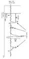
도 1은 만성 통증을 진단하고 치료하기 위한 예시적인 시스템의 개략도이다.
도 2는 신경을 자극하는 데, 신경 섬유 활동을 차단하기 위해 대상 신경의 주변에 직접 전기 에너지를 전달하는 데, 그리고 신경을 절제하는 데 이용되는 예시적인 프로브의 사시 측면도이다.
도 3은 신경을 자극하는 데, 신경 섬유 활동을 차단하기 위해 대상 신경의 주변에 직접 전기 에너지를 전달하는 데, 그리고 신경을 절제하는 데 이용되는 다른 예시적인 프로브의 사시 측면도이다.
도 4(a)는 다양한 진폭들, 지연시간들, 및 형상들을 갖는 유발 전위들을 나타낸 그래프이다. 파선은 트리거 시각, 또는 자극 펄스의 시작을 나타낸다.
도 4(b)는 단일의 자극(수직 파선)에 의해 유도되는 다수의 유발 전위들을 나타낸 그래프이다. 플롯 A는 △t0의 지연시간으로 유도되는 유발 전위를 나타내고, 여기서 유발 전위는 이어서 규칙적인 간격들(△t1=△t2=△t3)로 재발생한다. 플롯 B는 와인드업(wind-up)이라고 불리우는 현상을 나타내고, 여기서 자극은, 각각의 발생에서 주파수가 증가하는, 재발생하는 유발 전위들을 유도한다.
도 4(c)는 신경 절제 또는 고주파 신경 차단 이전(플롯 A) 그리고 그 이후(플롯 B)에 기록된 유발 전위 활동을 나타내는 그래프이다. 유발 전위는 플롯 A에서 자극(수직 파선) 이후에 나타내어져 있고 플롯 B에는 존재하지 않는다.
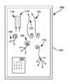
도 5는 만성 통증의 진단 및 치료에서 사용될 수 있는 예시적인 키트의 평면도이다.
도 6은 건강한 신경(실선 파형)의 단일의 자극(수직 파선)에 의해 유도된 유발 전위를 만성 통증과 연관된 신경(파선 파형)과 비교하는 그래프이다.
본 명세서 및 도면들에서의 참조 문자들의 반복 사용은 본 발명의 동일하거나 유사한 특징들 또는 요소들을 나타내려는 것이다.BRIEF DESCRIPTION OF THE DRAWINGS The full and enabling disclosure of the present invention to one of ordinary skill in the art is described in more detail in the remainder of the specification, including the best mode thereof, with reference to the accompanying drawings.
1 is a schematic diagram of an exemplary system for diagnosing and treating chronic pain.
FIG. 2 is an isometric side view of an exemplary probe used to deliver electrical energy directly to the periphery of a target nerve to excite the nerve, to block nerve fiber activity, and to excise the nerve.
Figure 3 is a perspective side view of another illustrative probe used to stimulate the nerve, to deliver electrical energy directly to the periphery of the target nerve to block nerve fiber activity, and to excise the nerve.
Figure 4 (a) is a graph showing evoked potentials with various amplitudes, delay times, and shapes. The dashed line indicates the trigger time or the start of the stimulation pulse.
4 (b) is a graph showing a number of induced potentials induced by a single stimulus (vertical dashed line). Plot A shows the induced potential induced in the delay time of Δt0 , where the induced potential then regresses at regular intervals (Δt1 = Δt2 = Δt3 ). Plot B represents the phenomenon called wind-up, where the stimulus induces recurring evoked potentials, where the frequency increases at each occurrence.
Fig. 4 (c) is a graph showing the evoked potential activity recorded prior to neurotomy or high frequency nerve block (plot A) and thereafter (plot B). The induced potential is shown after the stimulus (vertical dashed line) in plot A and not in plot B.
5 is a top view of an exemplary kit that may be used in the diagnosis and treatment of chronic pain.
Figure 6 is a graph comparing the evoked potentials induced by a single stimulus (vertical dashed line) of a healthy nerve (solid line waveform) to a nerve (dashed line waveform) associated with chronic pain.
The repeated use of reference characters in the present specification and drawings is intended to represent the same or similar features or elements of the present invention.
정의들Definitions
본원에서 사용되는 바와 같이, 용어 "뇌파 모니터링"이란, 기본 활동, 자발적 활동, 또는 유도된 활동일 수 있는, 뇌에서의 신경 또는 신경계 활동(neural or neurological activity)을 관찰하는 것을 지칭한다. 관찰은 뇌파 검사(EEG) 또는 임의의 다른 적당한 수단을 통해 전극들을 통한 것일 수 있다. 환언하면, 뇌파 모니터링이란 뇌파도(electroencephalogram) 상에 표현되는 바와 같은 뇌에서의 전위(electrical potential)를 관찰하는 것을 지칭한다.As used herein, the term "EEG monitoring" refers to observing neural or neurological activity in the brain, which may be a baseline activity, a spontaneous activity, or an induced activity. Observations may be via electrodes via EEG or any other suitable means. In other words, EEG monitoring refers to observing the electrical potential in the brain as expressed on the electroencephalogram.
본원에서 사용되는 바와 같이, 용어 "유발 전위"란 신경 자극에 응답한 신경계 활동의 결과 척도(outcome measure)를 지칭한다. 예를 들어, 유발 전위란 신경 자극에 응답한 신경계 활동의 버스트(burst)를 지칭할 수 있다.As used herein, the term "evoked potential" refers to the outcome measure of neural activity in response to a nerve stimulus. For example, an evoked potential can refer to a burst of nervous system activity in response to a nerve stimulus.
본원에서 사용되는 바와 같이, 용어 "저주파 전기 신경 자극"이란 유발 전위(evoked potential)(EP)를 유도하는 파형으로 저주파 전기 에너지를 인가하는 것을 지칭한다. 비제한적인 예로서, 저주파 전기 신경 자극이 전달되는 주파수는 약 100 헤르츠(Hz) 이하일 수 있다.As used herein, the term "low frequency electrical nerve stimulation" refers to the application of low frequency electrical energy to a waveform that induces an evoked potential (EP). By way of non-limiting example, the frequency at which the low frequency electric nerve stimulus is delivered may be less than about 100 hertz (Hz).
본원에서 사용되는 바와 같이, 용어 "고주파 전기 신경 차단 자극"이란 자극 또는 차단 부위를 통한 활동 전위(action potential)들의 전파를 차단하는 파형으로 고주파 전기 에너지를 인가하는 것을 지칭한다. 비제한적인 예로서, 고주파 전기 신경 자극이 전달되는 주파수는 약 1,000 Hz부터 약 100,000 Hz까지의 범위에 있을 수 있다.As used herein, the term "high-frequency electrical nerve block stimulation" refers to the application of high frequency electrical energy to a waveform that blocks the propagation of action potentials through stimulation or blocking sites. By way of non-limiting example, the frequency at which the high frequency electrical nerve impulse is delivered may range from about 1,000 Hz to about 100,000 Hz.
본원에서 사용되는 바와 같이, 용어 "신경 절제"란 (예컨대, 교류 전류에 의한) 초고주파 자극을 사용하여 통증 신호들의 뇌로의 전송을 방해하기 위해 신경에 병소를 생성하는 것을 지칭한다. 신경 절제는 절제가 수행되는 신경과 연관된 장기 통증 완화를 제공할 수 있다.As used herein, the term "neurosurgical" refers to the generation of lesions in the nerve to interfere with the transmission of pain signals to the brain using microwave stimulation (e.g., by alternating current). Neurosurgery can provide long-term pain relief associated with the nerves undergoing ablation.
본원에서 사용되는 바와 같이, 용어 "신경 손상"이란, 신경 또는 신경 경로에서 또는 그 주위에서 비롯되는 신경계(예컨대, 통증) 신호들이 손상된 부위를 통해 전송되지 않도록, 신경 또는 신경 경로의 임의의 차단, 변경, 파괴, 병소 형성(lesioning), 또는 절제를 지칭한다.As used herein, the term "nerve damage" refers to any block of the nerve or nerve pathway, such that nervous system (e.g., pain) signals originating at or around the nerve or nerve pathway are not transmitted through the damaged area, Alteration, destruction, lesioning, or resection.
본원에서 사용되는 바와 같이, 용어 "신경 차단"이란 뉴런의 축삭을 따라서 임펄스들이 통과하는 것을 가역적으로 또는 일시적으로 방해, 저해, 또는 방지하는 것을 지칭한다. 이 용어는 또한 뉴런의 축삭을 따라서 임펄스들이 통과하는 것을 일시적으로 방해, 저해, 또는 방지하여, 신경을 정상적으로 동작하지 못하게 만드는 것에 의해 신체의 일부에 무감각이 생성되는 한 형태의 부위 마취(regional anesthesia)를 포괄할 수 있다.As used herein, the term "nerve block" refers to reversibly or temporarily interfering with, inhibiting, or preventing the passage of impulses along the axons of neurons. The term also refers to a type of regional anesthesia in which anesthesia is created in a part of the body by temporarily interfering with, impeding, or preventing the passage of impulses along the axons of the neurons, .
본원에서 사용되는 바와 같이, 용어 "신경 경로"란 신경계의 하나의 부분을 다른 부분과 연결시키는 수단을 지칭한다.As used herein, the term "nerve pathway" refers to a means of linking one part of the nervous system to another part.
본원에서 사용되는 바와 같이, 용어 "신경 자극"이란, 전기 자극, 기계적 자극, 열 자극(극저온 에너지를 가하는 것을 포함하지만 이들로 제한되지 않음), 또는 화학적 자극(이들로 제한되지 않음)과 같은, 신경을 자극하는 임의의 수단을 지칭한다.As used herein, the term "nerve stimulation" is intended to mean any stimulation, such as electrical stimulation, mechanical stimulation, thermal stimulation (including, but not limited to, applying cryogenic energy), or chemical stimulation, Refers to any means of stimulating the nerve.
본원에서 사용되는 바와 같이, 용어 "초고 전기 신경 자극(ultra-high electrical nerve stimulation)"이란 자극 부위를 통한 유발 전위들의 전파를 방지 또는 저지하기 위해 신경을 충분히 손상시키는 파형으로 초고주파 전기 에너지를 가하는 것을 지칭한다. 비제한적인 예로서, 초고주파 전기 신경 자극이 전달되는 주파수는 약 100,000 Hz 초과일 수 있다.As used herein, the term "ultra-high electrical nerve stimulation" refers to the application of ultra-high frequency electrical energy to a waveform that sufficiently damages the nerve to prevent or inhibit the propagation of evoked potentials through the stimulation site Quot; By way of non-limiting example, the frequency at which the microwave electric nerve stimulus is delivered may be greater than about 100,000 Hz.
대표적인 실시예들의 상세한 설명DETAILED DESCRIPTION OF EXEMPLARY EMBODIMENTS
이제부터 본 발명의 다양한 실시예들이 상세히 언급될 것이며, 그 중 하나 이상의 예들이 이하에서 기술된다. 각각의 예는 본 발명에 대한 제한이 아니라 본 발명의 설명으로서 제공된다. 사실, 본 발명에 다양한 수정들 및 변형들이 본 발명의 범주 또는 사상을 벗어남이 없이 행해질 수 있다는 것이 본 기술분야의 통상의 기술자에게는 명백할 것이다. 예를 들어, 일 실시예의 일부로서 예시되거나 기술된 특징들이 다른 추가의 실시예를 만들어내기 위해 다른 실시예에서 사용될 수 있다. 이와 같이, 본 발명이 첨부된 청구항들 및 그의 등가물들의 범주 내에 속하는 이러한 수정들 및 변형들을 포함하는 것으로 의도되어 있다.Various embodiments of the invention will now be described in detail and one or more examples thereof are described below. Each example is provided as a description of the invention rather than as a limitation thereof. Indeed, it will be apparent to those of ordinary skill in the art that various modifications and variations can be made to the present invention without departing from the scope or spirit of the invention. For example, features illustrated or described as part of one embodiment may be used in other embodiments to create other additional embodiments. As such, the invention is intended to cover such modifications and variations as fall within the scope of the appended claims and their equivalents.
일반적으로 말하면, 본 발명은 신경 자극 및 뇌파 모니터링을 통해 만성 통증과 연관된 신경 경로를 식별하는 시스템 및 방법에 관한 것이다. 만성 통증이 급성 통증과 비교하여 뇌의 상이한 부위들에서 그리고 상이한 활성화 패턴들로 관찰되기 때문에, 본 시스템 및 방법이 급성 통증과 구별되는 만성 통증의 근원들을 식별할 수 있다는 것을 잘 알 것이다. 만성 요통의 신경계 마커(neurological marker)들(예컨대, 비정상적 신경 활동)이 사람의 뇌의 내측 전전두엽 피질 및 배외측 전전두엽 피질(dorsolateral prefrontal cortex)로부터 기록되었다. 대상포진후 신경통 환자들에서의 무해자극 통증(allodynia pain)은 섬 피질(insula cortex), S2, 및 기저핵(basal ganglia)에서의 활동에 의해 표시된다. 이와 유사하게, 골관절염(osteoarthritis)을 가진 사람들에서의 통증은 주로 섬 피질에 의해 표시된다. 본 발명의 시스템 및 방법은 만성 통증의 원인이 되는 신경 경로를 대상 신경의 제1 자극을 통해 식별하고, 이어서 올바른 대상 신경이 식별되었다는 것을 대상 신경의 제2 자극을 통해 검증할 수 있다. 그 후에, 만성 통증이 대상 신경의 제3 자극을 통해 치료될 수 있다. 그에 부가하여, 만성 통증과 연관되지 않은 부가의 신경이 부가의(제4) 자극을 통해 자극될 수 있고, 그에 따른 유도된 반응은, 만성 통증과 연관된 신경으로부터의 유도된 반응이 건강한 신경으로부터의 유도된 반응과 상이한 특성들을 가질 것이기 때문에, 대상 신경이 만성 통증의 근원이라는 부가의 검증을 제공하는 데 기준 반응(reference response)으로서 사용될 수 있다.Generally speaking, the present invention relates to a system and method for identifying a neural pathway associated with chronic pain through nerve stimulation and EEG monitoring. It will be appreciated that the present system and method can identify the sources of chronic pain distinct from acute pain, since chronic pain is observed in different areas of the brain and in different activation patterns as compared to acute pain. Neurological markers of chronic back pain (e. G., Abnormal neuronal activity) have been recorded from the medial prefrontal cortex and dorsolateral prefrontal cortex of the human brain. Allodynia pain in patients with postherpetic neuralgia is indicated by activity in the insula cortex, S2, and basal ganglia. Similarly, pain in people with osteoarthritis is marked primarily by the islands cortex. The system and method of the present invention can identify a neural pathway that causes chronic pain through a first stimulus of the subject's nerve and then verify that the correct target nerve has been identified through the second stimulus of the subject's nerve. Thereafter, chronic pain can be treated through the third stimulation of the target nerve. In addition, additional neurons not associated with chronic pain can be stimulated through additional (fourth) stimuli, and the resulting response is that the induced response from the neurons associated with chronic pain is due to The target nerve can be used as a reference response to provide additional assurance that it is the source of chronic pain.
하나 이상의 관심 대상 신경들의 제1 자극을 수행하기 위해, 대상 신경을 자극하기 위해 프로브가 원하는 위치에 위치될 수 있고, 여기서 자극되는 대상 신경은 만성 통증의 근원인 것으로 의심되고 있다. 이어서, 제1 신경 자극이 프로브로부터 대상 신경에 전달될 수 있고, 여기서 자극은 뇌에서의 만성 통증 반응을 유도하기에 충분하고, 제1 신경 자극의 결과로서의 뇌에서의 유발 전위 활동이 모니터링될 수 있다. 예를 들어, 만성 통증 반응이 유도되도록 충분히 높은 세기(예컨대, 전류) 또는 전압으로 자극이 전달될 수 있다.To perform a first stimulation of one or more nerves of interest, a probe may be positioned at a desired location to stimulate the target nerve, wherein the stimulated target nerve is suspected to be a source of chronic pain. A first nerve stimulus can then be delivered from the probe to the subject nerve, where the stimulus is sufficient to induce a chronic pain response in the brain, and the evoked potential activity in the brain as a result of the first nerve stimulation can be monitored have. For example, a stimulus may be delivered at a sufficiently high intensity (e.g., current) or voltage to induce a chronic pain response.
다양한 실시예들에서, 만성 통증과 연관된 신경 경로를 식별하기 위해 상이한 유형들의 모니터링이 수행될 수 있다. 하나의 특정 실시예에서, 뇌의 하나 이상의 미리 결정된 영역들에서의 유발 전위 활동이 모니터링될 수 있고, 뇌의 하나 이상의 미리 결정된 영역들에서 유발 전위 활동이 존재하는 것은 그 지점에서 자극되는 대상 신경이 만성 통증과 연관된 신경 경로의 일부라는 것을 나타낼 수 있다.In various embodiments, different types of monitoring may be performed to identify the neural pathways associated with chronic pain. In one particular embodiment, the evoked potential activity in one or more predetermined regions of the brain can be monitored, and the presence of evoked potential activity in one or more predetermined regions of the brain indicates that the target neuron May be part of a neural pathway associated with chronic pain.
다른 실시예에서, 제1 신경 자극이 전달될 수 있고, 이와 동시에, 뇌의 한 부위에서의 유발 전위 진폭들이 측정될 수 있다. 게다가, 프로브가 만성 통증의 근원인 것으로 의심되는 부위 주위에서 이동되기 때문에, 제1 신경 자극이 일정한 파형, 펄스 지속기간, 주파수, 세기, 또는 이들의 조합으로 전달될 수 있다. 이러한 모니터링에서, 유발 전위 측정을 이전의 유발 전위 진폭 측정들과 비교할 때 유발 전위 진폭의 증가는 프로브가 만성 통증의 근원에 보다 가깝게 위치되어 있다는 것을 나타낼 수 있다. 한편, 유발 전위 진폭 측정을 이전의 유발 전위 진폭 측정들과 비교할 때 유발 전위 진폭의 감소는 프로브가 만성 통증의 근원으로부터 보다 멀리 떨어져 위치되어 있다는 것을 나타낼 수 있다.In another embodiment, the first nerve stimulus may be delivered, and at the same time, the excitation potential amplitudes at one portion of the brain may be measured. In addition, since the probe is moved around a region suspected of being a source of chronic pain, the first nerve stimulus may be delivered in a given waveform, pulse duration, frequency, intensity, or a combination thereof. In such monitoring, when comparing evoked potential measurements to previous evoked potential amplitude measurements, an increase in evoked potential amplitude may indicate that the probe is located closer to the source of chronic pain. On the other hand, when comparing evoked potential amplitude measurements to previous evoked potential amplitude measurements, a reduction in evoked potential amplitude may indicate that the probe is located farther away from the source of chronic pain.
다른 실시예에서, 제1 신경 자극이 전달될 수 있고, 그에 따른 유발 전위들 사이의 지연시간이 측정될 수 있다. 이러한 실시예에서, 프로브가 만성 통증의 근원인 것으로 의심되는 부위 주위에서 이동되기 때문에, 제1 신경 자극이 일정한 파형, 펄스 지속기간, 주파수, 세기, 또는 이들의 조합으로 전달될 수 있다는 것을 잘 알 것이다. 이러한 모니터링에서, 2개의 유발 전위들 사이의 시간을 이전에 측정된 유발 전위들 사이의 시간과 비교할 때 유발 전위들 사이의 지연시간의 감소는 프로브가 만성 통증의 근원에 보다 가깝게 위치되어 있다는 것을 나타낼 수 있다. 한편, 2개의 유발 전위들 사이의 시간을 이전에 측정된 유발 전위들 사이의 시간과 비교할 때 유발 전위들 사이의 지연시간의 증가는 프로브가 만성 통증의 근원으로부터 보다 멀리 떨어져 위치되어 있다는 것을 나타낼 수 있다. 한편, 제1 신경 자극의 결과로서 그에 따른 유발 전위들 사이의 주파수가 또한 측정될 수 있고, 여기서 시간에 따라 측정된 유발 전위들의 주파수의 증가는 프로브가 만성 통증의 근원에 보다 가깝게 위치되어 있다는 것을 나타낼 수 있는 반면, 단위 시간당 측정된 유발 전위들의 수를 비교할 때 시간에 따라 측정된 유발 전위들의 주파수의 감소는 프로브가 만성 통증의 근원으로부터 보다 멀리 떨어져 위치되어 있다는 것을 나타낼 수 있다.In another embodiment, the first nerve stimulus may be delivered, and the delay time between the resulting excitons may be measured. In this embodiment, it is well known that the first nerve stimulus can be delivered with a constant waveform, pulse duration, frequency, intensity, or a combination thereof, since the probe is moved around a site suspected to be a source of chronic pain. will be. In this monitoring, a reduction in the delay time between evoked potentials when comparing the time between two evoked potentials to the time between previously measured evoked potentials indicates that the probe is located closer to the source of chronic pain . On the other hand, when comparing the time between two evoked potentials with the time between previously measured evoked potentials, an increase in the delay time between evoked potentials may indicate that the probe is located farther away from the source of chronic pain have. On the other hand, the frequency between the induced potentials as a result of the first nerve impulse can also be measured, wherein an increase in the frequency of the induced potentials measured over time indicates that the probe is located closer to the source of chronic pain , Whereas a decrease in the frequency of the induced potentials measured over time when comparing the number of measured evoked potentials per unit time may indicate that the probe is located farther away from the source of chronic pain.
또 다른 실시예에서, 제1 신경 자극 동안 모니터링하는 것은 만성 통증이 나타날 수 있는 뇌의 내측 전전두엽 피질, 배외측 전전두엽 피질, 섬 피질, 또는 임의의 다른 부위(이들로 제한되지 않음)와 같은, 뇌의 하나 이상의 미리 결정된 영역들에서 유발 전위 활동에 대해 모니터링하는 것을 포함할 수 있다. 만성 통증 알고리즘을 통해 결정되는 바와 같은 미리 결정된 진폭, 미리 결정된 지연시간, 미리 결정된 주파수, 미리 결정된 형상, 또는 이들의 조합을 갖는 유발 전위 활동이 뇌의 하나 이상의 미리 결정된 영역들에 존재하면, 자극되고 있는 대상 신경이 만성 통증과 연관된 신경 경로의 일부인 것으로 결론내려질 수 있다. 게다가, 유발 전위 활동이 존재하는 뇌의 영역은 겪고 있는 특정 유형 또는 유형들의 만성 통증을 결정하는 데 사용될 수 있다.In yet another embodiment, monitoring during the first nerve impulse can include monitoring the brain, such as, but not limited to, the inner prefrontal cortex of the brain, the extra-lateral prefrontal cortex, the isthmus, or any other region of the brain where chronic pain may be present. Lt; RTI ID = 0.0 > and / or < / RTI > If an evoked potential activity with a predetermined amplitude, a predetermined delay time, a predetermined frequency, a predetermined shape, or a combination thereof, as determined through a chronic pain algorithm, is present in one or more predetermined regions of the brain, May be concluded to be part of the nerve pathway associated with chronic pain. In addition, the area of the brain in which the evoked potential activity is present can be used to determine the chronic pain of the particular type or types suffering.
또 다른 실시예에서, 제1 신경 자극 동안 모니터링하는 것은 미리 결정된 자극 수단, 레벨, 사이클, 또는 파라미터에서 또는 그 동안에 유발 전위 진폭, 지연시간, 주파수, 형상 또는 이들의 조합을 측정하는 것을 포함할 수 있다. 이러한 실시예에서, 미리 결정된 자극 수단, 레벨, 사이클, 또는 파라미터에서 충분한 진폭, 지연시간, 주파수, 형상, 또는 이들의 조합을 갖는 유발 전위가 관찰되는 것은, 만성 통증이 본 발명의 시스템 및 방법을 사용하여 치료될 수 있도록, 대상 신경이 만성 통증과 연관된 신경 경로의 일부에 충분히 가깝게 근접하여 있다는 것을 나타낼 수 있다.In yet another embodiment, monitoring during the first nerve stimulation may include measuring induced excitation amplitude, delay time, frequency, shape, or a combination thereof at or during predetermined stimulation means, level, cycle, or parameter have. In such an embodiment, the observation of a triggering potential with sufficient amplitude, delay time, frequency, shape, or a combination thereof at a predetermined stimulus means, level, cycle, or parameter indicates that chronic pain is caused by the system and method of the present invention May indicate that the subject nerve is close enough to a portion of the nerve pathway associated with chronic pain so as to be able to be used with the subject.
대상 신경이 만성 통증과 연관된 신경 경로의 일부로서 식별되었으면, 만성 통증 반응이 유도되었다는 것을 나타내기 위해, 충분한 진폭, 지연시간, 주파수, 형상, 또는 이들의 조합을 갖는 유발 전위 활동이 관찰된 대상 신경을 따라 있는 위치와 같은 곳에서, 프로브로부터 제2 신경 자극이 전달될 수 있다. 제2 신경 자극은 신경 차단을 생성하기에 충분할 수 있다. 게다가, 제2 신경 자극의 전달 동안 뇌파 활동이 모니터링될 수 있고, 신경 차단의 적용 동안 유효 신경 차단과 부합하는 뇌파 활동이 관찰되면(예컨대, 유발 전위 활동이 최소한으로 관찰되거나 전혀 관찰되지 않으면) 대상 신경이 만성 통증과 연관된 신경 경로의 일부로서 올바르게 식별되었다고 확인될 수 있다. 한편, 신경 차단 동안 유효 차단과 부합하지 않는 뇌파 활동이 관찰되면(예컨대, 상당한 유발 전위 활동이 관찰되면) 대상 신경이 만성 통증과 연관된 신경 경로의 일부가 아니라고 확인될 수 있다.If the subject nerve has been identified as part of a neural pathway associated with chronic pain, then the subject nerve observed to have evoked potential activity with sufficient amplitude, delay time, frequency, shape, or a combination thereof to indicate that a chronic pain response has been induced The second nerve stimulus may be delivered from the probe. The second nerve stimulus may be sufficient to generate nerve block. In addition, if EEG activity can be monitored during delivery of the second nerve impulse and EEG activity consistent with effective nerve block during application of the nerve block is observed (e. G., Evoked potential activity is minimally observed or not observed at all) It can be confirmed that the nerve has been correctly identified as part of the nerve pathway associated with chronic pain. On the other hand, if EEG activity that is inconsistent with effective interception during nerve blockade is observed (for example, when significant evoked potential activity is observed), it can be confirmed that the subject nerve is not part of the nerve pathway associated with chronic pain.
대상 신경이 만성 통증과 연관된 신경 경로의 일부라고 식별한 후에, 그리고 임의로 대상 신경이 신경 차단을 통해 올바르게 식별되었다는 검증 이후에, 만성 통증이 제3 신경 자극을 통해 치료될 수 있다. 예를 들어, 충분한 진폭, 지연시간, 주파수, 형상, 또는 이들의 조합을 갖는 유발 전위 활동이 관찰되는 대상 신경을 따라 있는 위치에서 프로브로부터 제3 신경 자극이 전달될 수 있고, 여기서 제3 신경 자극은 만성 통증과 연관된 신경 경로를 손상시키기에 충분하다. 그 후에, 대상 신경의 유효 손상을 확인하거나 검증하기 위해 제1 신경 자극, 제2 신경 자극, 또는 둘 다가 반복될 수 있고, 여기서 신경 경로의 유효 손상과 부합하는 뇌파 활동이 관찰되면(예컨대, 유발 전위 활동이 최소한으로 관찰되거나 전혀 관찰되지 않으면) 손상이 완료되거나 충분하다.Chronic pain can be treated through the third nerve stimulation after the target nerve is identified as part of the nerve pathway associated with chronic pain, and optionally after verification that the target nerve has been correctly identified through nerve blockade. For example, a third nerve stimulus may be delivered from the probe at a location along the subject nerve where evoked potential activity with sufficient amplitude, delay time, frequency, shape, or combination thereof is observed, wherein the third nerve stimulus Is sufficient to damage the nerve pathways associated with chronic pain. Thereafter, the first nerve stimulation, the second nerve stimulation, or both can be repeated to confirm or verify the effective damage of the target nerve, where an EEG activity consistent with effective damage of the nerve pathway is observed (e.g., If dislocation activity is observed to a minimum or not observed at all, the damage is complete or sufficient.
다른 실시예에서, 대상 신경 이외의 부가의 신경을 따라 있는 위치에서 부가의(제4) 신경 자극이 프로브로부터 전달될 수 있고, 여기서 부가의 신경은 만성 통증의 근원인 것으로 의심되지 않는다. 그에 따른 유도된 반응 또는 유발 전위 활동이 대상 신경의 제1 신경 자극으로부터의 유도된 반응과 비교될 수 있다. 예를 들어, 부가의 신경의 자극으로 인한 유도된 반응이 나타내는 진폭, 지연시간, 주파수, 형상, 또는 이들의 조합은 건강한 신경으로부터의 유도된 반응 또는 유발 전위가 어떻게 나타나는지에 대한 기준으로서 역할할 수 있으며, 이는 대상 신경의 유도된 반응 또는 유발 전위가 부가의 신경의 유도된 반응 또는 유발 전위와 비교하여 모습이 구별되거나 상이하면 대상 신경이 만성 통증과 연관된 신경 경로의 일부라는 검증으로서 사용될 수 있다.In another embodiment, an additional (fourth) nerve stimulus may be delivered from the probe at a location along the additional nerve other than the subject nerve, wherein the additional nerve is not suspected to be a source of chronic pain. So that the induced response or evoked potential activity can be compared to the induced response from the first nerve stimulation of the target nerve. For example, the amplitude, delay time, frequency, shape, or combination thereof that an induced response due to the stimulation of an additional nerve may serve as a basis for how induced responses or evoked potentials from healthy nerves appear , Which can be used as a validation that the target nerve is part of the nerve pathway associated with chronic pain if the induced response or evoked potential of the target nerve is differentiated or differentiated compared to the induced response or evoked potential of the additional nerve.
앞서 기술된 신경 자극들의 특정의 유형은, 전기적, 기계적, 화학적인 것 등과 같이, 다양할 수 있다. 전달되는 신경 자극의 유형에 관계없이, 신경 자극이 경피적 프로브와 같은 프로브를 통해, 또는 임의의 다른 적당한 수단에 의해 전달될 수 있다는 것을 잘 알 것이다. 프로브에 부가하여, 본 발명의 시스템은 뇌파 검사(EEG) 모니터, 및 EEG 전극들을 포함할 수 있다. 하나의 특정 실시예에서, 본 시스템은 제1(저주파) 전기 신경 자극을 신경에 전달하기 위해 - 이 때 신경 자극과 연관된 뇌의 부위에서의 유발 전위(EP)들은 만성 통증과 연관된 특정의 신경을 식별하는 수단인 EEG를 통해 관찰될 수 있음 - 프로브에 전기적으로 부착된 펄스 발생기를 추가로 포함할 수 있다. 그 후에, 펄스 발생기는 제2(고주파) 전기 신경 자극을 신경 차단으로서 역할하는 대상 신경에 전달할 수 있다. EEG 상의 EP들이 제2(고주파) 전기 신경 자극의 결과로서 사일런싱(silence)되면, 사용자는 대상 신경이 만성 통증의 원인이 되는 신경 경로(즉, 만성 통증 근원)와 연관되어 있다는 것을 검증할 수 있고, 이어서 통증이 더 이상 느껴지지 않도록 만성 통증의 원인이 되는 통증 경로를 충분히 수정하거나 파괴하기 위해, 병소를 형성하는 절제에 의해, 또는 임의의 다른 적당한 방법에 의해서와 같이, 제3(초고주파) 전기 신경 자극을 통해 신경 또는 신경 경로를 손상시킬 수 있다. 성공적인 손상/절제는 이어서, 대상 신경의 유효 손상을 확인하기 위해, 손상/절제 부위에서의 제1(저주파) 전기 신경 자극, 절제 부위에서의 제2(고주파) 전기 신경 자극, 또는 둘 다를 반복하는 것을 통해 검증될 수 있고, 여기서 신경 경로의 유효 손상과 부합하는 뇌파 활동이 관찰되면 손상이 완료되었다. 예를 들어, EEG를 통해 측정되는 바와 같은 뇌에서의 EP들이 사일런싱되면, 사용자는 환자가 만성 통증을 더 이상 느끼지 않도록 환자의 만성 통증을 야기하는 신경이 성공적으로 손상되거나 절제되었다는 것을 검증할 수 있다. 비록 하나의 특정 실시예가 앞서 논의된 바와 같은 펄스 발생기를 통한 전기 신경 자극을 포함하지만, 신경 자극이 프로브 또는 다른 전달 디바이스를 사용하여 기계적, 화학적, 또는 다른 적당한 수단에 의해 수행될 수 있다는 것을 또한 잘 알 것이다. 이와 관련하여, 본 발명의 다양한 실시예들이 이제부터 이하에서 보다 상세히 논의될 것이다.The particular types of nerve impulses described above may vary, such as electrical, mechanical, chemical, and the like. It will be appreciated that regardless of the type of nerve impulse delivered, the nerve stimulus may be delivered via a probe, such as a percutaneous probe, or by any other suitable means. In addition to probes, the system of the present invention may include an electroencephalogram (EEG) monitor, and EEG electrodes. In one particular embodiment, the system is adapted to deliver a first (low-frequency) electrical nerve impulse to the nerve, wherein the evoked potentials (EPs) at the site of the brain associated with the nerve impulse are associated with a specific nerve associated with chronic pain Which can be observed through the EEG, which is a means of identifying the probe. The pulse generator may further include a pulse generator electrically attached to the probe. Thereafter, the pulse generator can deliver a second (high frequency) electrical nerve impulse to the target nerve that serves as a nerve block. If the EPs on the EEG are silenced as a result of the second (high frequency) electrical nerve stimulation, the user can verify that the target nerve is associated with a neural pathway (i.e., a chronic pain source) that causes chronic pain (Ultra-high frequency), such as by modifying or destroying the pain pathway that causes chronic pain so that the pain is no longer felt, by ablation that forms the lesion, or by any other suitable method, Electrical nerve stimulation can damage the nerve or nerve pathways. Successful impairment / ablation is then followed by a first (low-frequency) electrical nerve stimulation at the injured / ablated site, a second (high frequency) electrical nerve stimulation at the ablation site, or both , Where the damage was complete when EEG activity consistent with effective damage to the nerve pathway was observed. For example, if the EPs in the brain, such as those measured through the EEG, are silenced, the user can verify that the nerve causing the patient's chronic pain has been successfully damaged or ablated so that the patient no longer feels the chronic pain have. Although one particular embodiment includes electrical nerve stimulation through a pulse generator as discussed above, it is also well known that nerve stimulation can be performed by mechanical, chemical, or other suitable means using a probe or other delivery device I will know. In this regard, various embodiments of the present invention will now be discussed in more detail below.
이제 도면들 중 도 1을 참조하면, 제1(저주파) 전기 신경 자극을 통해 만성 통증과 연관되어 있거나 만성 통증의 원인이 되는 대상 신경을 찾아내고 그리고/또는 신경 경로를 식별할 수 있고, 대상 신경이 만성 통증의 근원이라는 것을 검증하기 위해 제2(고주파) 전기 신경 차단 자극을 대상 신경에 전달할 수 있으며, 대상 신경을 절제하거나 다른 방식으로 충분히 손상시키기 위해 제3(초고주파) 전기 신경 자극을 전달할 수 있고, 대상 신경이 성공적으로 절제되었다는 것을 보장하기 위해 제1(저주파) 전기 신경 자극, 제2(고주파) 전기 신경 자극, 또는 둘 다 중 어느 하나를 반복할 수 있는 만성 통증 관리 시스템이 예시되어 있다. 본 시스템은, 그 결과 얻어진 유도된 반응이, 대상 신경이 앞서 논의된 바와 같이 만성 통증과 연관된 신경 경로의 일부라는 것을 검증하기 위한 기준으로서, 사용될 수 있도록, 부가의(제4) 전기 신경 자극을 부가의 신경에 전달할 수 있다. 일반적으로, 전기 신경 자극(들)은 경피적 프로브를 이용하여 대상 신경에 전달될 수 있다. 만성 통증 관리 시스템은 미리 결정된 전압들, 주파수들, 진폭들(전류들) 등의 미리 결정된 전기 펄스들을 제어하고 하나 이상의 대상 신경(들)에 전달하는 다수의 디바이스들을 포함한다. 도 1에 도시된 바와 같이, 만성 통증 관리 시스템(100)은 전기 리드(120)에 의해 시스템(100)의 나머지 - 펄스 발생기(130), 사용자 인터페이스(140), 디스플레이(141), 및 제어기(150)를 포함함 - 에 연결되는 프로브(110)를 포함한다. 프로브는 경피적 프로브(110) 또는 임의의 다른 적당한 프로브일 수 있다. 본 시스템은 또한 환자 모니터링 시스템(160)을 포함하고, 격리된 전력 시스템(180)을 추가로 포함할 수 있다. 각각의 컴포넌트는 이하에서 보다 상세히 논의된다.Referring now to Figure 1 of the drawings, a first (low-frequency) electrical nerve stimulation can be used to identify and / or identify a nerve pathway that is associated with chronic pain or cause chronic pain, (High frequency) electrical nerve block stimulus can be delivered to the target nerve to verify that it is the source of chronic pain and can deliver a third (microwave) electrical nerve stimulus to ablate or otherwise adequately damage the target nerve There is illustrated a chronic pain management system capable of repeating either a first (low frequency) electrical nerve stimulation, a second (high frequency) electrical nerve stimulation, or both to ensure that the target nerve has been successfully ablated . The system is further adapted to perform additional (fourth) electrical nerve stimulation so that the resulting induced response can be used as a criterion to verify that the subject nerve is part of a neural pathway associated with chronic pain as discussed above. It can transmit to the additional nerve. Generally, the electrical nerve stimulus (s) can be delivered to the target nerve using a percutaneous probe. A chronic pain management system includes a number of devices that control predetermined electrical pulses, such as predetermined voltages, frequencies, amplitudes (currents), and deliver them to one or more target neurons (s). 1, a chronic
프로브Probe
본 발명의 만성 통증 관리 시스템(100)에서 임의의 적당한 프로브(110)가 이용될 수 있지만, 도 2는 적당한 경피적 프로브(210)의 일 예를 보다 상세히 나타내고 있다. 도 2를 참조하면, 대상 신경(220)을 자극하기 위해 시스템(100)(도 1을 참조)에서 사용될 수 있는 프로브(210)가 도시되어 있다. 프로브(210)는, 그 중에서도 특히, 펄스 발생기(130)(도 1을 참조)를 조절하는 제어기(150)에 결합될 수 있고, 또한 복귀 분산 전극(return dispersive electrode)(208) 및 유체 조성물 주입을 위한, 주사기(이들로 제한되지 않음)와 같은, 유체 전달 메커니즘(fluid delivery mechanism)(210)을 포함할 수 있다. 펄스 발생기(130)는, RF(radiofrequency) 에너지와 같은, 에너지를 프로브(210)에 공급하도록 제어될 수 있는 반면, 제어기(150)는 또한 프로브(210)의 적어도 하나의 온도 센서로부터의 온도 피드백을 측정할 수 있다. 게다가, 프로브(210)의 전도성 영역(212)과 복귀 분산 전극(208) 사이의 임피던스 측정이 수행될 수 있다. 임피던스 측정은 특정 전기적 특성들을 가지는 신경 조직의 부위를 찾아내기 위해 프로브의 배치 동안 사용될 수 있다. 그에 부가하여, 이하에서 보다 상세히 논의되는 바와 같이, 제어기(150)는 뇌파 검사(EEG)에 의해 결정되는 유발 전위(EP)들, 심전도(ECG) 측정들, 근전도(EMG) 측정들, 또는 치료 시술(treatment procedure)에 대한 환자의 반응을 평가하기 위한 다른 수단에 응답할 수 있다.Although any
프로브(210)는 전도성 샤프트(214) 및 손잡이(216)를 포함할 수 있다. 전도성 샤프트(214)는 그의 외측 표면의 대부분을 따라 절연 코팅(218)을 가질 수 있고, 인접한 노출된 전도성 영역(212)에서 종단될 수 있다. 전도성 영역(212)은 에너지를 신경 경로(204)의 대상 신경(220)으로 전송하기 위해 동작가능할 수 있다. 그에 부가하여, 전도성 영역(212)은 프로브(210)를 신경 경로(204) 내로, 그 근방에 또는 그 주위에 침투시키는 데 그리고 프로브(210)를 원하는 대상 신경(220)으로 이동(navigation)시키는 데 도움을 줄 수 있다. 따라서, 본 기술 분야의 통상의 기술자라면 전도성 영역(212)이 다양한 크기들 및 형상들일 수 있고 본 발명에서 이용되는 프로브(210) 상의 다양한 위치들에 위치될 수 있다는 것을 잘 알 것이다. 예를 들어, 전도성 영역(212)은, 상이한 시술들의 요구사항들에 따라 형상이 달라져, 뾰족하거나, 예리하거나, 뭉툭하거나, 개방되어 있을 수 있다. 또한, 제1 실시예에서의 전도성 영역(212)의 길이가 약 2 mm 내지 약 10 mm이지만, 이 길이는 시술 요구사항들에 따라 달라질 수 있다. 전도성 영역(212)은 임의로 의료 등급의 스테인리스강으로 제조될 수 있지만, 다른 전도성 생체적합성 재료들도 사용될 수 있다.The
일 실시예에서, 샤프트(214) 및 전도성 영역(212)은 전도성 재료, 예를 들어, 스테인리스강으로 제조될 수 있다. 한편, 절연 코팅(218)은 샤프트(214)가 고주파 전류를 샤프트(214)를 둘러싸고 있는 조직에 전달하지 못하게 하기 위해, 폴리에틸렌 테레프탈레이트 (PET)(이들로 제한되지 않음)를 비롯한, 임의의 유형의 절연성 재료로 제조될 수 있다. 게다가, 샤프트(214)는 일부 실시예들에서 적어도 하나의 개구(222) - 이를 통해 치료 조성물이 프로브(210)로부터 투여되어 빠져나갈 수 있음 - 를 가질 수 있다.In one embodiment, the
프로브(210)의 전도성 샤프트(214)는 전도성 영역(212)을 신경 경로(204)의 대상 신경(220)에 도달하도록 조종하는 것을 용이하게 하기 위해 프로브(210)에 강성을 부여할 수 있고, 이 경우에 샤프트(214)는 강성이거나 반강성이라고 지칭될 수 있다. 다른 실시예들에서, 샤프트(214)는 연성일 수 있다. 일 실시예에서, 샤프트(214)는 그의 길이를 따라서 중공(hollow) - 내강(lumen)을 정의함 - 일 수 있다. 샤프트(214)는 치료 조성물을 전도성 영역(212) 및/또는 대상 신경(220)으로 전달하는 데는 물론, 프로브(210)와 연관된 임의의 배선을 지지하고 둘러싸는 데 사용될 수 있다. 게다가, 샤프트(214)의 내경은, 샤프트(214)의 원단부(distal end)와 연관된 온도 센서에 대한 배선에 부가하여, 개방 팁(open tip)을 갖는 실시예들에서 스타일릿(stylet) 또는 폐색구(obturator)를 수용하기에 충분한 크기로 되어 있을 수 있다. 일부 실시예들에서, 샤프트(214)의 길이는 약 5 cm와 약 15 cm 사이에서 변할 수 있다. 그렇지만, 대상 신경의 위치 및/또는 수행되는 시술에 따라, 길이가 이 범위를 넘어 변할 수 있다는 것을 잘 알 것이다.The
일 실시예에서, 손잡이(216)는, 샤프트(214)의 내강과 유체 연통되는, 그에 결합된 연성 튜브(224)를 포함할 수 있다. 튜브(224)의 연성은 프로브(210)의 보다 큰 조종성(maneuverability)을 가능하게 할 수 있다. 연성 튜브(224)의 근단부(proximal end)는 유체 전달 연계부분 접속부(fluid delivery interface connection)(226)에 결합될 수 있다. 다른 실시예들(도시되지 않음)에서, 손잡이(216)가 필요하지 않을 수 있고, 연성 튜브(224)가 샤프트(214)에 직접 결합될 수 있다. 사용자가 프로브(210)를 보다 쉽게 조작할 수 있게 하기 위해, 손잡이(216)가 임의로 그립(grip)(228)을 제공할 수 있다. 일 실시예에서, 손잡이(216)가, 예를 들어, 산화 에틸렌을 사용하여 살균될 수 있는 의료 등급의 사출 성형가능 플라스틱 또는 다른 재료로 제조된다. 손잡이(216)는 또한 샤프트(214)의 축을 따라서 개구(222)와 일렬로 맞춰져 있는 그리고 샤프트(214)의 축을 중심으로 한 개구(222)의 배향을 표시하는 데 사용될 수 있는 개구 마커(aperture marker)(230)를 가질 수 있다. 개구 마커(230)는 개구(222)의 배향을 표시하는 것에 의해 사용자가 치료 조성물의 전달을 위한 조직을 겨냥할 수 있게 한다. 손잡이(216)는, 샤프트(214)의 축을 중심으로 프로브(210)의, 예를 들어, 180° 회전을 표시하는 제1 배향 마킹들(232) 및 샤프트(214)의 축을 중심으로 프로브(210)의, 예를 들어, 90° 회전을 표시하는 제2 배향 마킹들(234)을 비롯한, 배향 마킹들을 추가로 포함할 수 있다. 사용자는 이어서, 프로브(210)가 신경 경로(204)에 또는 그 근방에 있는 신경 조직을 통해 삽입되는 동안 프로브(210)가 샤프트(214)의 축을 중심으로 회전하는 것을 방지하기 위해 또는 프로브(210)를 샤프트(214)의 축을 중심으로 원하는 배향으로 회전시키기 위해, 제1 및/또는 제2 배향 마킹들(232, 234)을 참조할 수 있다. 제1 및 제2 배향 마킹들(232, 234)은, 프로브(210)가 신경 경로(204)에 또는 그 근방에 있는 신경 조직 내로 삽입될 때 사용자가 마킹들(232, 234)을 보거나 느낄 수 있도록, 손잡이(216)와 동일 평면에 있을 수 있는 시각적 표시자들, 또는 텍스처 가공되거나 양각되어 있을 수 있는 촉각적 표시자들일 수 있다. 손잡이(216)의 근단부는 또한 변형 방지부(strain relief)(236)를 가질 수 있고, 그립(228)이 변형 방지부(236)의 근단부부터 원단부까지 연장되어 있다. 도 2에서, 그립(228)은, 프로브(210)가 샤프트(214)의 축을 중심으로 회전되고 신경 경로(204)에 또는 그 근방에 있는 신경 조직을 통해 삽입되는 동안, 사용자에게 마찰점들을 제공하기 위해, 예를 들어, 평행한 융기부들로 텍스처 가공되어 있다. 이 실시예에서, 그립(228) 상의 융기부들은 또한 장치의 회전각을 결정하는 데 사용될 수 있다. 일 실시예에서, 변형 방지부(236)는, 정사각형, 삼각형, 또는 기계식 기어와 같이 "톱니형(toothed)"일 수 있는, 둥글지 않은(비원형) 단면을 가질 수 있다. 변형 방지부(236)는 손잡이(216)와 들어맞게 하기 위해 원위 외경이 보다 크고 전기 케이블(238)과 연성 튜브(224)를 고정시키기 위해 근위 외경이 보다 작도록 테이퍼져 있을 수 있다. 이 테이퍼는 사용자에게 증가된 악력을 제공하고 프로브(210)가 신경 경로(204)에 또는 그 근방에 있는 신경 조직 내로 전진될 때 사용자의 손가락들의 미끄러짐을 감소시킨다. 변형 방지부(236)는 편안한 손잡이를 사용자에게 제공할 수 있고, 사용자가 선호하는 잡기동작(gripping preference)에 부합할 수 있다. 도 2에서, 전기 케이블(238)과 연성 튜브(224)는 손잡이(216) 및 변형 방지부(236)로부터 서로 평행하게 그리고 인접하여 연장되어 있다. 주목할 만한 것은, 이 실시예에서, 전기 케이블(238)과 연성 튜브(224)는 손잡이(216)로부터 서로 수직으로 연장되지 않는다. 이 배열은 편안한 파지(grasp)를 제공할 수 있고, 배치, 회전, 삽입 등 동안에 프로브(210)의 조작 편의성을 향상시킬 수 있다.In one embodiment, the
하나의 특정 실시예에서, 전기 에너지가, 전기 커넥터(240), 전기 케이블(238) 및 전도성 샤프트(214)를 포함하는, 전기적 결합부(electrical coupling)를 거쳐 제어기(150)로부터 펄스 발생기(130)(도 1)를 통해 전도성 영역(212)에 공급될 수 있다. 전도성 영역(212)을 제외한, 모든 전기 접점들이 전기 커넥터(240) 내에 위치된 커넥터 핀 하우징에 의해 사용자로부터 격리되어 있을 수 있다. 전기 케이블(238)은 제어기(150)를, 펄스 발생기(130)(도 1)를 거쳐 전도성 영역(212)에 에너지를 공급하는, 전도성 샤프트(214)에 유연하게 결합시킬 수 있다. 전기 케이블(238)은 또한 온도 데이터를 다시 제어기(150)에 중계할 수 있다. 하나의 특정 실시예에서, 전기 케이블(238) 내의 하나의 도체는 열전쌍 전선은 물론 RF 전달 전선 둘 다로서 기능할 수 있다. 양 목적을 위해 단일의 도체를 이용하는 것은 전기 케이블(238)의 총 질량을 감소시키고 신경 경로(204)에 있는 신경 조직에, 그 근방에 또는 그 주위에 프로브를 배치하는 동안 손잡이(216)에 가해지는 힘과 모멘트를 최소화한다. 본 기술 분야의 통상의 기술자라면 개별적인 케이블들 및/또는 도체들이 대안적으로 온도 센서와 함께 사용될 수 있다는 것을 잘 알 것이다.In one particular embodiment, electrical energy is transferred from
그에 부가하여, 유체 전달 메커니즘(210)은, 환자의 신체 내의 조직의 영역에 치료 조성물을 투여하는 것을 가능하게 하기 위해, 유체 전달 연계부분 접속부(226)에 그리고 그를 통해 연성 튜브(224)를 거쳐 샤프트(214)에 유연하게 결합될 수 있다. 따라서, 프로브(210)는 그와 동시에 대상 신경(220)을 치료하기 위해 유체 전달 메커니즘(211) 및 펄스 발생기(130)(도 1)에 연결될 수 있다. 유체 전달 연계부분 접속부(226)는 유체 전달 메커니즘(211)으로부터 연성 튜브(224)로의 유체의 흐름을 가능하게 하는, 루어형 커넥터(luer type connector)(이들로 제한되지 않음)를 비롯한, 임의의 커넥터를 포함할 수 있다.In addition, the
동작 중에, 프로브(210)는 신경 경로(204) 근방의 부위 내로, 예컨대, 대상 신경(220)에 삽입된다. 프로브(210)의 적절한 배치는, 이하에서 보다 상세히 논의되는 바와 같이, 대상 신경(220)을 자극하기 위해 전도성 영역(212)을 사용하여 전기 에너지를 인가하는 것에 의해 확인될 수 있다. 마취 유체(anesthetic fluid) 또는 다른 치료 조성물이 유체 전달 메커니즘(211)을 작동시키는 것에 의해 임의로 투여될 수 있다. 마취제를 비롯한, 약리학적 제제(pharmacological agent)들 이외에, 투여되는 치료 조성물은, 예를 들어, 전기 전도성인 유체 또는, 원하는 경우, 조직을 가열 또는 냉각시키기 위해 사용되는 유체를 포함할 수 있다. 치료 조성물은 유체 전달 메커니즘(211)을 빠져나가 유체 전달 연계부분 접속부(226), 연성 튜브(224), 및 샤프트(214)의 내강을 통해 전도성 영역(212)으로 흐를 수 있고, 전도성 영역(212)에서 치료 조성물은 개구(222)를 통해 빠져나간다. 프로브(210) 내에 유체 전달 시스템을 포함시키는 것은 유체 전달 메커니즘(211)이 유체 전달 연계부분 접속부(226)에 사전 연결될 수 있게 하고, 이는 치료 조성물을 투여하기 위해 별도의 장치를 사용하고 따라서 그를 제거할 필요 - 이로 인해 일반적으로 전도성 영역(212)의 위치가 조절될 것임 - 가 없게 하는 것에 의해 전도성 영역(212)의 부주의한 움직임의 가능성을 감소시킬 수 있다. 그에 부가하여, 연성 튜브(224)의 사용은, 치료 조성물을 투여하기 위해 유체 전달 메커니즘(211)이 작동될 때, 예를 들어, 주사기에 있는 플런저가 눌러질 때, 손잡이(216) 및 샤프트(214)에 작용하는 힘을 추가로 감소시킬 수 있다. 따라서, 프로브(210)의 적절한 배치를 확인하기 위한 자극 이후에, 프로브(210)의 수동 조작이 최소화되고, 이에 따라 프로브(210) 그리고 따라서 전도성 영역(212)이 제자리를 벗어나 이동할 가능성이 감소된다. 더욱이, 원단부가 예리하거나 뾰족한 샤프트(214)를 갖는 프로브(210)의 사용은, 별도의 인트로듀서 튜브(introducer tube) 또는 니들(needle)을 먼저 삽입할 필요 없이, 프로브(210)가 삽입될 수 있게 하고, 따라서 프로브(210)의 위치 이동의 가능성을 추가로 감소시킨다. 그렇지만, 인트로듀서(introducer)가 또한 사용될 수 있고, 본 발명의 범주 내에 속하는 것으로 간주된다In operation, the
임의로 치료 조성물을 투여한 후에, RF(radio frequency) 에너지가 전도성 영역(212)을 통해 대상 신경(220)에 가해질 수 있다. 프로브(210)가 대상 신경(220)과 접촉하여 전기적으로 작동될 때 폐회로(closed circuit)를 생성하기 위해 복귀 분산 전극(208)이 제공된다. 유체 전달 메커니즘(211)이 에너지 전달 동안 프로브(210)에 여전히 연결되어 있기 때문에, 에너지의 전달과 동시에 치료 조성물을 전달하는 것이 가능하다는 것을 잘 알 것이다. 신경 자극 및/또는 치료 동안, 제어기(150)를 통한 프로브(210)의 안전한 제어를 보장하는 데 도움을 주기 위해 대상 신경(220)에 전달되는 RF(radiofrequency) 에너지를 자동으로 제어하기 위해 온도 센서 피드백이 사용될 수 있다. 예를 들어, 온도 센서 피드백 메커니즘에 의해 측정되는 바와 같이 RF 에너지를 가하는 동안 신체 조직 온도가 빠르게 증가하면, 예컨대, 어느 시술 또는 단계가 수행되고 있는지에 기초하여, 원하는 설정된 온도로의 제어된 램프(controlled ramp)를 제공하기 위해 대상 신경(220)으로의 RF 에너지 전달이 일시 중지되거나 감소될 수 있다. 이러한 방식으로, 사용자는 RF 에너지를 신경 조직에 맹목적으로 가하지 않고, RF 에너지 전달이 조직 온도에 미치는 영향을 실시간으로 통보받는다.After optionally administering the therapeutic composition, radio frequency (RF) energy may be applied to the
일부 실시예들에서, 이전에 기술된 바와 같이, 연성 튜브(224)는 유체 전달이 추가된 힘을 프로브(210)에 유입시키지 않도록 보장하기 위해 필요한 기계적 이완(mechanical slack)을 제공할 수 있다. 다른 치료 도구(들)(242)가, 시술에 따라, 또한 프로브(210)에 유연하게 연결될 수 있다. 프로브(210)는 따라서 프로브(210)에 유연하게 결합되는 이 치료 도구들을 위한 미리 형성된 커넥터들을 구비할 수 있다.In some embodiments, as previously described, the
도 3은 적당한 경피적 프로브(310)의 다른 실시예를 나타내고 있다. 프로브(310)는 리드(120)를 거쳐 제어기(150)에 그리고 펌프 케이블(311), 하나 이상의 근위 냉각 공급 튜브(proximal cooling supply tube)들(312), 및 하나 이상의 근위 냉각 복귀 튜브(proximal cooling return tube)들(314)을 거쳐 하나 이상의 냉각 디바이스들(308)에 결합될 수 있다. 프로브는 또한 제어기(150)에 의해 제어되는 펄스 발생기(130)(도 1)에 결합될 수 있다. 도 3에 도시된 바와 같이, 리드(120)의 원위 영역(324)은, 프로브(310)가 리드(120)에 연결될 수 있도록, 리드(120)를 2개의 원단부들(336)로 분할할 수 있는 분할기(splitter)(330)를 포함할 수 있다. 한편, 리드(120)의 근단부(328)는 제어기(150)에 연결된다. 이 연결은 영구적 - 그에 의해, 예를 들어, 리드(120)의 근단부(328)는 제어기(150) 내에 매립됨 - 일 수 있거나, 일시적 - 이 경우, 예를 들어, 리드(120)의 근단부(328)는 전기 커넥터를 거쳐 제어기(150)에 연결될 수 있음 - 일 수 있다. 리드(120)의 2개의 원단부들(336)은 또한 프로브(310)에 결합하도록 동작가능한 커넥터들(340)에서 종단될 수 있고, 프로브(310)와 제어기(150) 사이에 전기적 연결을 구축할 수 있다.FIG. 3 shows another embodiment of a suitable
하나 이상의 냉각 디바이스들(308)이 사용될 수 있고 프로브(310)에 그리고 그에 근접하여 위치된 재료의 온도를 감소시키는 임의의 수단을 포함할 수 있다. 냉각 디바이스(308)는 냉각 디바이스(308)로부터 하나 이상의 근위 냉각 공급 튜브들(312), 프로브(310), 하나 이상의 근위 냉각 복귀 튜브들(314)을 통해, 그리고 다시 냉각 디바이스(308)로 유체를 순환시키도록 동작가능한 2개의 연동 펌프(peristaltic pump)들을 포함할 수 있다. 유체는 물 또는 임의의 다른 적당한 유체일 수 있다. 다른 실시예들에서, 냉각 디바이스(308)는 하나의 연동 펌프만을 또는 하나 이상의 전열 냉각 디바이스들 또는 임의의 다른 냉각 수단을 포함할 수 있다. 냉각 디바이스(308)는 제어기(150)와 적어도 단방향으로 그리고 임의로 양방향으로 통신하도록 동작가능할 수 있다. 이러한 방식으로, 냉각 디바이스(308)와 제어기(150) 사이에 피드백 제어가 구축될 수 있다. 피드백 제어는 제어기(150), 프로브(310), 및 냉각 디바이스(308)를 수반하지만, 임의의 2개의 디바이스들 사이의 임의의 피드백이 또한 생각되고 있다. 피드백 제어가, 예를 들어, 제어기(150)의 컴포넌트일 수 있는 제어 모듈에서 구현될 수 있다. 이 실시예에서, 제어기(150)는 프로브(310)와는 물론 냉각 디바이스(308)와도 양방향으로 통신하도록 동작가능할 수 있고, 여기서 양방향 통신이란 디바이스가 다른 디바이스로부터 신호를 수신하기도 하고 다른 디바이스로 신호를 송신하기도 할 수 있는 것을 지칭한다.One or
피드백 제어의 일 예로서, 제어기(150)는 프로브(310)로부터 온도 측정들을 수신할 수 있다. 예를 들어, 온도 측정들에 기초하여, 제어기(150)는, 펄스 발생기(130)(도시되지 않음)로부터 프로브(310)로 송신되는 전력을 변조하는 것과 같은, 어떤 동작을 수행할 수 있다. 예를 들어, 프로브(310)에의 전력은 온도 측정이 낮을 때 증가되거나 측정이 높을 때 감소될 수 있을 것이다. 어떤 경우에, 제어기(150)는 프로브(310)에의 전력을 중단시킬 수 있다. 이와 같이, 제어기(150)는 프로브(310)로부터 신호(예컨대, 온도 측정)를 수신하고, 적절한 조치를 결정하며, 신호(예컨대, 감소된 또는 증가된 전력)를 다시 프로브(310)로 송신할 수 있다. 대안적으로, 제어기(150)는 프로브(310)에 공급되는 냉각의 유량 또는 정도를 증가시키거나 감소시키기 위해 신호를 하나 이상의 냉각 디바이스(308)로 송신할 수 있다.As an example of feedback control, the
대안적으로, 하나 이상의 냉각 디바이스들(308)이 하나 이상의 연동 펌프들을 포함하면, 하나 이상의 펌프들은 유체 유량을 제어기(150)에 전달할 수 있고, 이 유량을 변조하라고 펌프들에 지시하는 통신을 제어기(150)로부터 수신할 수 있다. 어떤 경우에, 하나 이상의 연동 펌프들은 유량을 변경하거나 어떤 기간 동안 턴오프하는 것에 의해 제어기(150)에 응답할 수 있다. 냉각 디바이스들(308)이 턴오프될 때, 프로브(310)와 연관된 어떤 온도 감지 요소들도 냉각 유체에 의해 영향을 받지 않을 것이고, 주변의 조직 온도의 보다 정확한 결정이 행해질 수 있게 한다.Alternatively, if the one or
또 다른 실시예들에서, 하나 이상의 냉각 디바이스들(308)은 냉각 속도를 감소시키거나 프로브(310)와의 거리에 따라 연결 해제(disengage)될 수 있다. 예를 들어, 원하는 온도를 달성하기에 충분한 전류 밀도가 그 영역에 존재할 정도로 거리가 충분히 작을 때, 냉각이 거의 또는 전혀 필요하지 않을 수 있다. 이러한 실시예에서, 에너지는 치료될 신경 조직의 영역을 통해 제1 및 제2 에너지 전달 디바이스들(392) 사이에 우선적으로 집중되고, 그에 의해 띠 모양의 병소(strip lesion)를 생성한다. 띠 모양의 병소는 활성 전극이 유사한 크기의 복귀 전극에 아주 근접하여 있을 때 형성되는 길쭉한 체적의 가열된 조직에 의해 특징지워진다. 이것이 일어나는 이유는, 주어진 전력에서, 전류 밀도가 전극들 사이에 우선적으로 집중되고 전류 밀도로 인해 온도의 상승이 발생하기 때문이다.In still other embodiments, one or
냉각 흐름이 방해받는 경우 또는 하나 이상의 냉각 디바이스들(308)의 뚜껑(lid)이 열려 있는 경우와 같이, 하나 이상의 냉각 디바이스들(308)과 연관된 하나 이상의 가능한 오류들 및/또는 이상(anomaly)들을 제어기(150)에 경고하기 위해 하나 이상의 냉각 디바이스들(308)이 또한 발생기(130)와 통신할 수 있다. 발생기(130)는 이어서 오류 신호에 따라 사용자에게 경고하는 것, 시술을 중단하는 것, 및 동작을 수정하는 것 중 적어도 하나에 의해 기능할 수 있다.One or more possible errors and / or anomalies associated with the one or
또 다른 실시예들에서, 제어기(150)가 하나 이상의 냉각 디바이스들(308) 중 하나와만 통신할 수 있거나, 디바이스들 사이의 통신이 단방향일 수 있다. 예를 들어, 하나 이상의 냉각 디바이스들(308)이 제어기(150)로부터 들어오는 신호들을 수신하도록 동작가능할 수 있지만, 신호들을 다시 제어기(150)로 송신하도록 동작가능하지 않을 수 있다. 전술한 피드백 시스템들에 부가하여, 제어기(150)는, 이하에서 논의되는 바와 같이, 뇌파 검사(EEG)에 의한 유발 전위(EP)들, 심전도(ECG) 측정들, 근전도(EMG) 측정들, 또는 치료 시술에 대한 환자 반응의 어떤 다른 척도에 대응하고, 이어서 그에 따라 대응할 수 있다.In yet other embodiments, the
도 3에 예시된 바와 같이, 하나 이상의 냉각 디바이스들(308)과 제어기(150) 사이의 통신을 용이하게 하는 수단은 제어기(150)를 하나 이상의 냉각 디바이스들(308)에 전기적으로 연결시키는 펌프 케이블(311)의 형태를 취할 수 있다. 다른 실시예들에서, 제어기(150)와 하나 이상의 냉각 디바이스들(308)은 RS-232 케이블, 광섬유 케이블, USB 케이블, FirewireTM (IEEE 1394) 케이블 또는 다른 전기적 결합 수단에 의해 연결될 수 있다. 다른 추가 실시예들에서, 제어기(150)와 하나 이상의 냉각 디바이스들(308) 사이의 통신은 적외선, 무선, 블루투스TM 및 다른 것들(이들로 제한되지 않음)을 비롯한 어떤 다른 통신 프로토콜을 사용하여 달성될 수 있고, 본 발명이 이와 관련하여 제한되지 않는다.As illustrated in Figure 3, the means for facilitating communication between the one or
도 3에 예시된 바와 같이, 하나 이상의 근위 냉각 공급 튜브들(312)은 하나 이상의 근위 냉각 공급 튜브들(312)의 원단부들에 있는 근위 공급 튜브 커넥터들(316)을 포함할 수 있다. 그에 부가하여, 하나 이상의 근위 냉각 복귀 튜브들(314)은 하나 이상의 근위 냉각 복귀 튜브들(314)의 원단부들에 있는 근위 복귀 튜브 커넥터들(318)을 포함할 수 있다.As illustrated in FIG. 3, one or more proximal
일 실시예에서, 프로브(310)는 근위 영역(360), 손잡이(380), 가늘고 긴 중공 샤프트(384), 및 에너지 전달 디바이스들(392)을 포함하는 원위 선단 영역(390)을 포함할 수 있다. 근위 영역(360)은 원위 냉각 공급 튜브(362), 원위 공급 튜브 커넥터(366), 원위 냉각 복귀 튜브(364), 원위 복귀 튜브 커넥터(368), 프로브 어셈블리 케이블(370), 및 프로브 케이블 커넥터(372)를 포함할 수 있다. 이 실시예에서, 원위 냉각 공급 튜브(362)와 원위 냉각 복귀 튜브(364)는 프로브(310)의 보다 큰 조종성을 가능하게 하기 위해 연성일 수 있지만, 강성 튜브들을 갖는 대안의 실시예들이 가능하다.In one embodiment, the
일 실시예에서, 근위 공급 튜브 커넥터(316)는 원위 공급 튜브 커넥터(366)와 서로 맞물리도록 동작가능할 수 있고, 근위 복귀 튜브 커넥터(318)는 원위 복귀 튜브 커넥터(368)와 서로 맞물리도록 동작가능할 수 있다. 이것은 프로브(310)의 모듈성을 유지하면서 냉각 유체가 흐를 수 있는 회로를 구축하는 데 도움을 준다.In one embodiment, the proximal
그에 부가하여, 도 3에 예시된 실시예에서, 프로브 케이블 커넥터(372)는 프로브 어셈블리 케이블(370)의 근단부에 위치될 수 있고, 커넥터들(340) 중 하나에 무방향으로(reversibly) 결합하도록 동작가능할 수 있으며, 이로써 제어기(150)와 프로브(310) 사이에 전기적 연결을 구축한다. 프로브 어셈블리 케이블(370)은 프로브(310)의 특정 구성에 따라 하나 이상의 도체들을 포함할 수 있다. 예를 들어, 프로브 어셈블리 케이블(370)은 프로브 어셈블리 케이블(370)이 RF 전류를 펄스 발생기(130)(도 1)로부터, 제어기(150)에 의해 결정되는 바에 따라, 에너지 전달 디바이스(392)로 전송할 수 있게 하는 것은 물론, 이하에서 논의되는 바와 같이 다수의 온도 감지 디바이스들을 제어기(150)에 연결시킬 수 있게 하는 5개의 도체들을 포함할 수 있다.3, the
에너지 전달 디바이스(392)는 에너지를 원위 선단 영역(390)에 인접한 신경 조직의 영역으로 전달하는 임의의 수단을 포함할 수 있다. 예를 들어, 에너지 전달 디바이스(392)는, 이하에서 논의되는 바와 같이, 펄스 발생기(130)로부터의 RF(radio frequency) 에너지를 포함할 수 있다. 일 실시예에서, 에너지 전달 디바이스(392)는 전극을 포함한다. 전극의 활성 영역은 길이가 2 밀리미터(mm) 내지 20 mm일 수 있고, 전극에 의해 전달되는 에너지는 RF 범위에 있는 전류의 형태의 전기 에너지일 수 있다. 일부 실시예들에서, 제어기(150)로부터의 피드백은 임피던스 또는 온도와 같은 주어진 측정에 응답하여 에너지 전달 디바이스(392)의 노출된 면적을 자동으로 조절할 수 있다. 이것은 에너지 전달 디바이스(392)와 연관된 조절가능 절연 슬리브(adjustable insulation sleeve)의 사용을 통해 달성될 수 있다. 절연 슬리브의 조절은 슬리브를 에너지 전달 디바이스를 따라 근위로(proximally) 또는 원위로(distally) 슬라이딩시키는 것을 통해 달성될 수 있다. 다른 실시예들에서, 조절이 수동으로 행해질 수 있다. 대안적으로, 에너지 전달 디바이스(392)에 근접한 원위 선단 영역(390)을 따라 부가의 전도성 영역들이 제공될 수 있다. 이러한 실시예에서, 절제 시술 동안 생성되는 병소의 크기 또는 형상과 같은, 신경 손상의 정도는 부가의 전도성 영역들 중 하나 이상 및 에너지 전달 디바이스(392)를 통해 에너지를 선택적으로 전달하는 것에 의해 변경될 수 있다. 게다가, 하나 이상의 에너지 전달 디바이스(392)는, 본 기술 분야에 널리 공지된 바와 같이, 활성 전극들과 복귀 전극들의 임의의 조합을 포함할 수 있다.The
도 2 및 도 3이 이용될 수 있는 적당한 프로브들의 예들이라는 것을 잘 알 것이다. 그렇지만, 다른 적당한 프로브들이 이용될 수 있고, Hillier 등의 미국 특허 제7,306,596호, Godara 등의 미국 특허 제8,187,268호, 및 Leung 등의 미국 특허 제8,740,897호 - 이들 각각은 이로써 그 전체가 참고로 포함됨 - 에 기술되어 있다. 게다가, 신경 자극을 대상 신경에 전달하기 위해 하나 초과의 프로브(310)가 이용될 수 있고, 여기서 다수의 프로브들은 신경 자극의 전달을 위해 펄스 발생기 내의 다수의 채널들에 연결될 수 있으며(이하에서 논의됨), 여기서 각각의 채널은 만성 통증의 상이한 위치 또는 근원을 치료하는 데 사용될 수 있다는 것을 또한 잘 알 것이다. 예를 들어, 제1 프로브는 상부 등(upper back)의 제1 부위를 치료하기 위해 펄스 발생기의 제1 채널에 연결될 수 있고, 제2 프로브는 등(back)의 제2 부위를 치료하기 위해 펄스 발생기의 제2 채널에 연결될 수 있으며, 제3 프로브는 등의 제3 부위를 치료하기 위해 제3 채널에 연결될 수 있고, 제4 프로브는 등의 제4 부위를 치료하기 위해 제4 채널에 연결될 수 있다.It will be appreciated that Figures 2 and 3 are examples of suitable probes that can be used. However, other suitable probes may be used and are described in U.S. Patent No. 7,306,596 to Hillier et al., U.S. Patent No. 8,187,268 to Godara et al, and U.S. Patent No. 8,740,897 to Leung et al., Each of which is hereby incorporated by reference in its entirety, Lt; / RTI > In addition, more than one
펄스 발생기Pulse generator
이제 도 1로 돌아가서, 프로브(110)는 전기 리드(120)를 통해 펄스 발생기(130)에 연결될 수 있다. 일 실시예에서, 펄스 발생기(130)는 바이폴라 정전류 자극기(bipolar constant current stimulator)일 수 있다. 하나의 예시적인 자극기는 영국의 Digitimer Ltd.로부터 입수가능한 DIGITIMER DS5 전기 자극기이다. 다른 정전류 및 정전압 펄스 발생기들이 사용될 수 있다. 게다가, 앞서 나타낸 바와 같이, 펄스 발생기는 만성 통증의 다수의 근원들 또는 위치들의 치료를 가능하게 하기 위해 다수의 채널들을 포함할 수 있고, 여기서 다수의 프로브들이 다수의 채널들에 연결된다. 이러한 방식으로, 만성 통증의 각각의 근원 또는 위치가 필요한 경우 상이한 자극 레벨로 치료될 수 있는데, 그 이유는 각각의 프로브가 펄스 발생기로부터의 자극을 그 자신의 채널을 통해 전달할 수 있기 때문이다.Returning now to FIG. 1, the
사용자 인터페이스User interface
본 시스템은 또한 사용자 인터페이스(140)를 이용할 수 있다. 이 사용자 인터페이스(140)는 제어기(150)와 상호작용하는 컴퓨터의 형태로 되어 있을 수 있고, 격리 시스템(180)에 의해 전력을 공급받을 수 있으며, 각각이 본원에서 기술된다.The system may also utilize the
컴퓨터는 제어기로부터 전달되는 신호들을 기록하도록 그리고 제어기의 출력을 구동하도록 설계된 소프트웨어를 작동시킨다. 가능한 소프트웨어는 Cambridge Electronic Design(UK)의 SPIKE 프로그램을 포함한다. 소프트웨어는 프로그래밍가능하고, EP들, EEG 신호들, ECG 신호들, 및 EMG 신호들과 같은 전기 생리학적 신호(electrophysiological signal)들을 기록하고 분석할 수 있으며, 자극을 전달하라고 제어기에 지시할 수 있다.The computer activates software designed to record signals transferred from the controller and to drive the output of the controller. Possible software includes Cambridge Electronic Design (UK) SPIKE program. The software is programmable and can record and analyze electrophysiological signals such as EPs, EEG signals, ECG signals, and EMG signals, and can direct the controller to deliver stimuli.
게다가, 사용자 인터페이스(140)는 모니터(141)를 포함할 수 있고, 모니터는 디스플레이 화면(도시되지 않음)을 통해 다수의 뷰들을 보여주도록 구성될 수 있다. 예를 들어, 제1 뷰는 만성 통증의 근원을 식별해주는 것에 관련된 정보를 디스플레이할 수 있고, 제2 뷰는 만성 통증의 근원을 검증해주는 것에 관련된 정보를 디스플레이할 수 있으며, 제3 뷰는 만성 통증을 치료하는 것에 관련된 정보를 디스플레이할 수 있다.In addition, the
환자 모니터링 시스템Patient monitoring system
환자 모니터링 시스템(160)이 또한 본 발명의 시스템에서 사용될 수 있다. 환자 모니터링 시스템은 생리학적 신호들을 취득하고, 증폭하며, 필터링할 수 있고, 또한 그들을 제어기(150)로 출력할 수 있다. 본 시스템은 뇌로부터 전기 신호들 그리고 구체적으로는 유발 전위(EP)들을 수집하기 위해 뇌파도(EEG) 모니터(170)를 포함한다. 뇌파도 모니터(170)는 교류 전류(AC) 증폭기(200A)와 결합된 EEG 전극들(172)을 포함한다. 전극들은 뇌의 임의의 부위의 전기적 활동이 모니터링될 수 있도록 본 기술분야의 통상의 기술자에 공지된 임의의 적당한 방식으로 환자의 두피 상에 위치될 수 있다. 일부 실시예들에서, 3개 내지 128개의 전극들이 이용될 수 있다. 예를 들어, 두피 또는 임의의 다른 적당한 위치 상에 배치하는 것을 통해 EEG 측정들을 획득하기 위해 5개, 16개, 32개, 또는 64개의 전극들이 이용될 수 있다. 구체적으로는, 특정 레벨의 전기 에너지가, 앞서 논의되고 도 2 및 도 3에 도시된 프로브들 중 하나와 같은, 경피적 프로브를 통해 대상 신경 근방의, 그 주위의 또는 그 상의 부위에 인가될 때, 대응하는 유발 전위 활동의 진폭, 전기 신경 자극의 인가와 제1 EP들의 시작 사이의 지연시간, 하나의 EP의 끝과 차후의 EP들의 시작 사이의 지연시간, 다수의 EP들의 버스트들이 존재할 때 각각의 EP의 주파수, 및 EP들의 형상을 측정하기 위해, 뇌의 임의의 부위에서의 EEG 측정들이 기록될 수 있다. 저주파 전기 신경 자극에서 이 정보의 정량적 분석을 통해, 만성 통증의 근원인 신경 경로와 연관된 대상 신경이 식별될 수 있고, 그 후에 만성 통증을 치료하기 위해 대상 신경이 차단되고 손상될 수 있다.A
도 4 (a)는 몇 개의 유발 전위들(1 내지 4)의 진폭, 지연시간 및 형상을 나타내는 그래프이다. 시간에서 수직 파선으로 표시되는 전기 자극에 의해 전위들이 유도된다. 자극 세기가 일정하면, 프로브와 신경 사이의 거리가 감소함에 따라 개별 버스트의 유발 전위 진폭은 증가할 것이고, 이는 의사가 프로브를 통증 회로 쪽으로 밀어넣는 데 도움을 준다. 대안적으로, 프로브와 신경 사이의 거리가 증가함에 따라 유발 전위의 진폭은 감소할 것이다.4 (a) is a graph showing the amplitude, delay time and shape of several evoked potentials (1 to 4). Potentials are induced by electric stimulation, which is represented by vertical dashed lines in time. If the stimulus intensity is constant, as the distance between the probe and the nerve decreases, the evoked potential amplitude of the individual burst will increase, which helps the physician push the probe into the pain circuit. Alternatively, as the distance between the probe and the nerve increases, the amplitude of the evoked potential will decrease.
다시 말하지만, EP의 진폭, 지연시간, 주파수, 및 형상은 뇌파 모니터링의 위치에 기초하여 만성 통증과 연관된 신경 경로를 찾아내는 데 도움을 줄 수 있다. 예를 들어, 신경 자극 시에 뇌의 하나 이상의 미리 결정된 영역들에서 EP 활동이 관찰되는 것은 자극되는 대상 신경이 만성 통증과 연관된 신경 경로의 일부라는 것을 나타낼 수 있다. 게다가, 다른 실시예에서, 미리 결정된 자극 수단, 레벨, 또는 파라미터에서 충분한 진폭, 지연시간, 주파수, 또는 형상의 EP가 관찰되는 것은 대상 신경에서의 만성 통증을 치료하기 위해 프로브를 통해 자극되는 대상 신경이 만성 통증과 연관된 신경 경로의 일부에 충분히 가깝게 근접하여 있다는 것을 나타낼 수 있다.Again, the amplitude, delay time, frequency, and shape of the EP can help to identify the neural pathways associated with chronic pain based on the location of EEG monitoring. For example, the observation of EP activity in one or more predetermined regions of the brain during a nerve stimulation may indicate that the stimulated target nerve is part of a neural pathway associated with chronic pain. Moreover, in other embodiments, the observation of EPs of sufficient amplitude, delay time, frequency, or shape at a predetermined stimulus means, level, or parameter may indicate that the target nerve being stimulated through the probe to treat chronic pain in the subject nerve May be close enough to some of the nerve pathways associated with chronic pain.
도 4(b)는 단일의 자극에 의해 활성화되는 다수의 유발 전위들을 나타내고 있다. 반복하는 전위들의 존재에 의해 만성 통증이 급성 통증과 구분가능할 수 있다고 생각된다. 플롯 A에서, 자극-유도 유발 전위(stimulation elicited evoked potential)는 △t0의 지연시간을 가지며, 도시된 바와 같이, 동일한 뉴런이 오래 지속되는 신경 진동 또는 연발(volley)에 가까운 규칙적인 간격들(예컨대, △t1= △t2 = △t3)로 계속하여 발화(fire)한다. 플롯 B는, 유발 전위들이 반복적으로 발생하지만 각각의 발생이 새로운 개수의 전위들 및 활성화 주파수들을 나타내는, "와인드업"이라고 알려져 있는 현상을 나타내고 있다.Figure 4 (b) shows a number of induced potentials activated by a single stimulus. It is thought that chronic pain can be distinguished from acute pain by the presence of repetitive dislocations. In plot A, stimulus-to induced evoked potential (stimulation elicited evoked potential) is △ t has a delay time of0, and, close to a regular interval in the same nerves vibration or volley (volley) which neuron is long-lasting, as shown ( For example, Δt1 = Δt2 = Δt3 ). Plot B shows a phenomenon known as "winding up" in which the excitation potentials occur repeatedly, but each occurrence represents a new number of potentials and activation frequencies.
도 4(c)는 절제전(pre-ablation)(플롯 A) 및 절제후(post-ablation)(플롯 B) 데이터 세그먼트를 나타내고 있다. 플롯 A에서, 데이터 트레이싱(data tracing)은 자발적 또는 기본 EEG 활동 및 전기 잡음과, 자극-유도 유발 전위(stimulus-elicited evoked potential)에 의해 나타내어진다. 신경의 절제 이후에, EEG 시스템에 의해 기록된 자발적 활동은 진폭 및 주파수가 감소되고, 자극(수직 파선)은 유발 전위를 유도할 수 없다.Figure 4 (c) shows the pre-ablation (plot A) and post-ablation (plot B) data segments. In plot A, data tracing is represented by spontaneous or basic EEG activity and electrical noise, and stimulus-elicited evoked potential. After excision of the nerve, spontaneous activity recorded by the EEG system is reduced in amplitude and frequency, and stimulation (vertical dashed line) can not induce evoked potentials.
앞서 논의된 실시예들에서, EEG 측정들의 높은 시간 분해능으로 인해, 어느 신경이 환자가 겪고 있는 만성 통증의 원인이 되는 신경 경로와 연관되어 있는지에 관한 결정이 실시간으로 행해질 수 있는데, 그 이유는 만성 통증이 프로브/EEG 시스템에 의해 유도되기 때문이다.In the embodiments discussed above, due to the high temporal resolution of the EEG measurements, a determination can be made in real time as to whether a neuron is associated with a neural pathway leading to a chronic pain patient is suffering from, Because the pain is induced by the probe / EEG system.
전술한 EEG 모니터(170)에 부가하여, 환자 모니터링 시스템(160)은 또한 심전도(ECG) 신호들을 수집하는 심박수 모니터(180) 및 근전도(EMG) 신호들을 수집하는 근육 활동 모니터(190)를 포함할 수 있다. 심박수 모니터(180)는 교류 전류(AC) 증폭기(200B)와 결합된 ECG 전극들(182)을 포함할 수 있다. 한편, 근육 활동 모니터(190)는 AC 증폭기(200C)와 결합된 EMG 전극들(192)을 포함할 수 있다. 어느 생리학적 파라미터들이 모니터링되어야 하는지에 따라 다른 유형들의 트랜스듀서들이 또한 사용될 수 있다. 기술되는 바와 같이, 환자 모니터링 시스템에 의해 획득되는 모든 생리학적 신호들이 AC 신호 증폭기/컨디셔너(conditioner)(200A, 200B, 200C)를 통해 전달된다. 하나의 가능한 증폭기/컨디셔너는, 미국 로드 아일랜드 웨스트 워릭 소재의 Astro-Med, Inc.의 자회사인, Grass Technologies로부터 입수가능한 Model LP511 AC 증폭기이다.In addition to the EEG monitor 170 described above, the
격리된 전력 시스템Isolated power system
모든 기구들은 이러한 기구들을 지락 사고(ground fault)들 및 전기 간선(electrical main)에 의해 전달되는 전력 스파이크들로부터 보호하기 위해 격리된 전력 공급장치 또는 시스템(194)에 의해 전력을 공급받을 수 있다. 이용가능한 격리된 전력 시스템의 일 예는 미국 로드 아일랜드 웨스트 워릭 소재의 Astro-Med, Inc.의 자회사인 Grass Technologies로부터 Model IPS115 격리된 의료 등급의 전력 시스템이다.All apparatuses may be powered by an isolated power supply or
제어기Controller
EEG 데이터, ECG 데이터, EMG 데이터, RF 온도 데이터 등과 같은, 환자 모니터링 시스템(160)으로부터의 파형 데이터 및 디지털 정보를 기록할 수 있고 펄스 발생기(130)의 실시간 제어를 위한 파형 및 디지털 출력들을 동시에 발생시킬 수 있는 제어기(150)가 사용된다. 제어기(150)는, 고속 데이터 포착, 독립적인 파형 샘플 레이트들 및 온라인 분석을 용이하게 하기 위해 온보드 메모리를 가질 수 있다. 예시적인 제어기(150)는 Cambridge Electronic Design(UK)으로부터 입수가능한 POWER 1401 데이터 취득 인터페이스 유닛일 수 있다.Can record waveform data and digital information from the
전기 자극 파라미터들Electrical Stimulation Parameters
본 발명에서, 자극의 목적에 기초하여 상이한 전기 자극 파라미터들이 사용된다. 본 발명에 의해 고려되는 다양한 자극 파라미터들이 이하에서 보다 상세히 개별적으로 논의된다.In the present invention, different electrical stimulation parameters are used based on the purpose of stimulation. The various stimulation parameters contemplated by the present invention are discussed in greater detail below individually.
만성 통증을 유도하기 위한 제1(저주파) 전기 신경 자극First (low-frequency) electrical nerve stimulation to induce chronic pain
먼저, 뇌파 모니터링 동안 EEG를 통해 관찰되는 EP 활동의 존재 또는 그의 변화(즉, EP들의 진폭의 증가, 지연시간의 감소, 주파수의 증가, 또는 충분한 형상 변화)에 의해 결정되는 바와 같이, 환자의 만성 통증의 근원인 신경 경로인 것으로 의심되거나 그와 연관되어 있을 수 있는 대상 신경에 만성 통증 반응을 유도하기 위해, 저주파 전기 신경 자극 파라미터들이 이용된다. 제1(저주파) 전기 신경 자극이, 정전류로 또는 정전압으로와 같이, 일정한 파형, 펄스 지속기간, 주파수, 세기, 또는 이들의 조합으로 전달될 수 있다. 일반적으로 말하면, 전류 조절 자극(current regulated stimulus)들의 사용은 특정 상황들에서 전압 조절 자극(voltage regulated stimulus)들보다 장점이 있는데, 그 이유는 전류 밀도가 더 잘 제어될 수 있기 때문이다. 그에 부가하여, 자극이 단상(monophasic) 또는 2상(biphasic) 방식으로 전달될 수 있다. 게다가, 파형이 구형파, 사인파, 또는 펄스 열(pulse train)일 수 있다.First, the patient's chronological age, as determined by the presence or change in EP activity observed through the EEG during EEG monitoring (i. E., An increase in amplitude of EPs, a decrease in delay time, an increase in frequency, Low frequency electrical nerve stimulation parameters are used to induce a chronic pain response to a target nerve that may be suspected or associated with a nerve pathway that is the source of pain. The first (low-frequency) electrical nerve stimulation may be delivered in a constant waveform, pulse duration, frequency, intensity, or a combination thereof, such as at constant current or constant voltage. Generally speaking, the use of current regulated stimuli has advantages over voltage regulated stimuli in certain situations, since the current density can be better controlled. In addition, the stimulus may be delivered in a monophasic or biphasic manner. In addition, the waveform can be a square wave, a sine wave, or a pulse train.
더욱이, 제1(저주파) 전기 신경 자극이 인가되는 주파수는 전형적으로 약 100 헤르츠(Hz) 이하이다. 예를 들어, 제1(저주파) 전기 신경 자극이 인가되는 주파수는, 약 0.1 Hz부터 약 75 Hz까지와 같은, 약 0.1 Hz부터 약 50 Hz까지와 같은, 약 0.1 Hz부터 약 100 Hz까지의 범위에 있을 수 있다. 더욱이, 펄스 지속기간은, 약 0.05 밀리초(ms)부터 약 5 ms까지와 같은, 약 0.1 ms부터 약 2.5 ms까지와 같은, 약 0.01 ms부터 약 10 ms까지의 범위에 있을 수 있다. 그에 부가하여, 2상 펄스들에 대해, 펄스 지속기간은 펄스의 각각의 부분에 대해, 약 0.025 ms부터 약 2.5 ms까지와 같은, 약 0.05 ms부터 약 1.25 ms까지와 같은, 약 0.005 ms부터 약 5 ms까지의 범위에 있을 수 있다. 게다가, 인가되는 전류는, 약 0.25 밀리암페어(mA)부터 약 40 mA까지와 같은, 약 0.2 mA부터 약 30 mA까지와 같은, 약 0.01 mA부터 약 50 mA까지의 범위에 있을 수 있다. 또한, 하나의 펄스의 시작과 다음 펄스의 시작 사이의 시간의 양이고 위상 지속기간, 펄스내 간격(intrapulse interval)들, 및 펄스간 간격(interpulse interval)들을 포함하는, 펄스 주기는, 약 0.05 밀리초(ms)부터 약 20 ms까지와 같은, 약 0.1 ms부터 약 5 ms까지와 같은, 약 0.01 ms부터 약 20 ms까지의 범위에 있을 수 있다. 전술한 주파수 및 전류(세기) 범위들에 부가하여, 본 기술 분야의 통상의 기술자에 의해 이해되는 바와 같이, 주파수 및 전류 범위들의 다른 조합들이 본 발명에 의해 생각된다.Moreover, the frequency at which the first (low frequency) electrical nerve stimulus is applied is typically less than about 100 hertz (Hz). For example, the frequency at which the first (low-frequency) electrical nerve stimulus is applied may range from about 0.1 Hz to about 100 Hz, such as from about 0.1 Hz to about 50 Hz, such as from about 0.1 Hz to about 75 Hz. Lt; / RTI > Moreover, the pulse duration may range from about 0.01 ms to about 10 ms, such as from about 0.1 ms to about 2.5 ms, such as from about 0.05 ms to about 5 ms. In addition, for two-phase pulses, the pulse duration may range from about 0.005 ms to about 1.25 ms, such as from about 0.05 ms to about 1.25 ms, such as from about 0.025 ms to about 2.5 ms, for each portion of the pulse, 5 ms. ≪ / RTI > In addition, the applied current may range from about 0.01 mA to about 50 mA, such as from about 0.2 mA to about 30 mA, such as from about 0.25 mA (mA) to about 40 mA. Further, the pulse period, which includes the amount of time between the start of one pulse and the start of the next pulse and which includes phase duration, intrapulse intervals, and interpulse intervals, is about 0.05 milli-milliseconds For example, from about 0.01 ms to about 20 ms, such as from about 0.1 ms to about 5 ms, such as from about 1 ms to about 20 ms. In addition to the frequency and current (intensity) ranges described above, other combinations of frequency and current ranges are contemplated by the present invention, as will be understood by those of ordinary skill in the art.
차단을 위한 제2(고주파) 전기 신경 자극Second (high-frequency) electric nerve stimulation for interception
다음에, 앞서 논의된 제1(저주파) 전기 신경 자극 및 EP 활동의 EEG 측정들을 통해 대상 신경이 만성 통증의 근원인 신경 경로의 일부로서 올바르게 식별되었다는 것을 추가로 검증하기 위해, 제2(고주파) 전기 신경 차단 자극이 수행될 수 있다. 이러한 고주파 전기 신경 차단 자극은 올바한 신경(즉, 만성 통증 반응과 연관된 신경)이 제1(저주파) 전기 신경 자극 동안 뇌에서의 EEG를 통해 관찰된 만성 통증의 근원인 신경 경로의 일부로서 식별되었다는 것을 검증하기 위해 뉴런의 축삭을 따라서 임펄스들이 통과하는 것을 일시적으로 차단할 수 있다. 유효 신경 차단과 부합하는 뇌파 활동이 관찰되면, 올바른 신경이 만성 통증 근원인 신경 경로의 일부로서 식별되었다는 확인이 행해질 수 있다. 예를 들어, 고주파 전기 신경 차단 자극이 대상 신경에 전달된 것에 응답하여 자발적 만성 통증 활동 또는 EP 진폭의 상당한 감소 또는 사일런싱은, 자극의 시각과 EP의 시작 상의 지연시간의 증가, 다수의 EP들 사이의 지연시간의 증가, EP들의 주파수의 감소, 또는 EP들의 상당한 형상 변화와 같이, 대상 신경이 만성 통증의 근원과 연관되어 있고 올바르게 식별되었다는 것을 나타낼 수 있다. 한편, 유효 신경 차단과 부합하지 않는 뇌파 활동(예컨대, EP들)이 관찰되면, 대상 신경이 만성 통증과 연관된 신경 경로의 일부가 아니라는 확인이 행해질 수 있다. 예를 들어, 제2(고주파) 전기 신경 차단 자극이 대상 신경에 전달된 것에 응답하여 자발적 만성 통증 활동의 감소가 그다지 관찰되지 않거나 EP들의 진폭의 증가가 관찰된다면, 이것은 자극되는 대상 신경이 만성 통증의 근원과 연관되어 있지 않다는 것을 나타낼 수 있다. 마찬가지로, 신경 자극의 인가의 시각으로부터 제1 유발 전위의 시작까지의 지연시간의 변화가 거의 내지 전혀 없거나, 다수의 EP들 사이의 지연시간의 변화가 거의 내지 전혀 없거나, EP 형상의 변화가 거의 내지 전혀 없는 것은 자극되는 대상 신경이 만성 통증의 근원과 연관되어 있지 않다는 것을 나타낼 수 있다Next, in order to further verify that the target nerve was correctly identified as part of the neural pathway that is the source of chronic pain through EEG measurements of the first (low frequency) electric nerve stimulation and EP activity discussed above, the second (high frequency) Electrical nerve block stimulation can be performed. These high frequency electrical nerve block stimuli have been identified as being part of the nerve pathway where the right nerve (i. E., The nerves associated with the chronic pain response) is the source of chronic pain observed through the EEG in the brain during the first (low frequency) It is possible to temporarily block the passage of impulses along the neurons' axons. If EEG activity consistent with effective nerve block is observed, it can be verified that the correct nerve has been identified as part of the nerve pathway that is the source of chronic pain. For example, a significant reduction in the spontaneous chronic pain activity or EP amplitude or silencing in response to the delivery of the high frequency electrical nerve block stimulus to the target nerve may result in an increase in the time of stimulation and the delay time at the beginning of the EP, Such as a decrease in the frequency of the EPs, or a significant change in the shape of the EPs, may be associated with the source of chronic pain and correctly identified. On the other hand, if EEG activities (e. G., EPs) that are incompatible with effective nerve blockade are observed, confirmation may be made that the target nerve is not part of the nerve pathway associated with chronic pain. For example, if a decrease in spontaneous chronic pain activity is not observed or an increase in amplitude of EPs is observed in response to a second (high frequency) electrical nerve block stimulus being delivered to the target nerve, It is not related to the origin. Likewise, when there is little or no change in the delay time from the time of application of the nerve stimulation to the start of the first induced potential, or when there is little or no change in the delay time between multiple EPs, Nothing at all can indicate that the stimulated target nerve is not associated with a source of chronic pain
제2(고주파) 전기 신경 자극이, 정전류로 또는 정전압으로와 같이, 일정한 파형, 펄스 지속기간, 주파수, 세기, 또는 이들의 조합으로 인가될 수 있다. 그에 부가하여, 자극이 단상 또는 2상(가장 바람직함) 방식으로 전달될 수 있다. 게다가, 파형이 구형파, 사인파, 또는 펄스 열일 수 있고, 여기서 다수의 펄스들의 버스트들이 수 밀리초 내지 수 초 정도 전달될 수 있으며, 여기서 각각의 펄스 열은 버스트간 간격(interburst interval)인 오프 시간(가변적임, 환자에 특유함)만큼 분리되어 있다. 일반적으로, 고주파 전기 신경 차단 자극이 인가되는 주파수는 약 1,000 Hz부터 약 100,000 Hz까지의 범위에 있다. 예를 들어, 주파수는, 약 2,000 Hz부터 약 80,000 Hz까지와 같은, 약 2,500 Hz부터 약 70,000 Hz까지와 같은, 약 1,500 Hz부터 약 90,000 Hz까지의 범위에 있을 수 있다. 더욱이, 펄스 지속기간은, 약 10 마이크로초(μs)부터 약 400 μs까지와 같은, 약 20 μs부터 약 300 μs까지와 같은, 약 5 μs부터 약 500 μs까지의 범위에 있을 수 있다. 그에 부가하여, 2상 펄스들에 대해, 펄스 지속기간은 펄스의 각각의 부분에 대해, 약 10 마이크로초(μs)부터 약 200 μs까지와 같은, 약 20 μs부터 약 100 μs까지와 같은, 약 2.5 μs부터 약 250 μs까지의 범위에 있을 수 있다. 게다가, 인가되는 전류는, 약 0.25 mA부터 약 40 mA까지와 같은, 약 0.2 mA부터 약 30 mA까지와 같은, 약 0.01 mA부터 약 50 mA까지의 범위에 있을 수 있다. 더욱이, 펄스 주기는, 약 20 μs부터 약 800 μs까지와 같은, 약 40 μs부터 약 600 μs까지와 같은, 약 10 μs부터 약 1000 μs까지의 범위에 있을 수 있다. 전술한 주파수 및 전류(세기) 범위들에 부가하여, 본 기술 분야의 통상의 기술자에 의해 이해되는 바와 같이, 주파수 및 전류 범위들의 다른 조합들이 본 발명에 의해 생각된다.The second (high frequency) electrical nerve stimulation may be applied with a constant waveform, pulse duration, frequency, intensity, or a combination thereof, such as at constant current or constant voltage. In addition, the stimulus may be delivered in a single-phase or two-phase (most preferred) manner. In addition, the waveform may be a square wave, a sinusoidal wave, or a pulse train, where bursts of a plurality of pulses may be delivered from a few milliseconds to several seconds, where each pulse train is an off-time (interburst interval) Variable, unique to the patient). Generally, the frequency at which the high-frequency electrical nerve blocking stimulus is applied is in the range of about 1,000 Hz to about 100,000 Hz. For example, the frequency may range from about 1,500 Hz to about 90,000 Hz, such as from about 2,500 Hz to about 70,000 Hz, such as from about 2,000 Hz to about 80,000 Hz. Moreover, the pulse duration may range from about 5 microseconds to about 500 microseconds, such as from about 20 microseconds to about 300 microseconds, such as from about 10 microseconds (μs) to about 400 microseconds. In addition, for two-phase pulses, the pulse duration may be from about 20 microseconds to about 100 microseconds, such as from about 10 microseconds (μs) to about 200 microseconds, for each portion of the pulse, It can range from 2.5 μs to about 250 μs. In addition, the applied current may range from about 0.01 mA to about 50 mA, such as from about 0.2 mA to about 30 mA, such as from about 0.25 mA to about 40 mA. Moreover, the pulse period may range from about 10 μs to about 1000 μs, such as from about 40 μs to about 600 μs, such as from about 20 μs to about 800 μs. In addition to the frequency and current (intensity) ranges described above, other combinations of frequency and current ranges are contemplated by the present invention, as will be understood by those of ordinary skill in the art.
절제를 위한 제3(초고주파) 전기 신경 자극Third (very high frequency) electric nerve stimulation for ablation
대상 신경이 앞서 논의된 제1(저주파) 전기 신경 자극 및 EEG 측정들을 통해 만성 통증의 근원인 신경 경로의 일부로서 식별되었고, 임의로, 대상 신경이 또한 앞서 논의된 제2(고주파) 전기 신경 차단 자극을 통해 만성 통증과 연관된 신경 경로의 일부로서 올바르게 식별되었다고 검증되면, 대응하는 통증 신호를 뇌로 전송하는 것을 방지하기 위해, 환자의 만성 통증의 원인인 것으로 결정된 신경 경로가 손상될 수 있다. 예를 들어, 신경 경로가 절제와 같은 제3(초고주파) 전기 신경 자극을 사용하여 절제될 수 있고, 이 경우 신경 경로에 또는 그 근방에 병소가 형성된다. 그렇지만, 절제 이외의 임의의 다른 적당한 손상 방법이 또한 이용될 수 있다는 것도 잘 알 것이다. 예를 들어, 절제 이외에, 펄스형 RF 자극이 신경 경로를 변경하거나 손상시키기 위해 인가될 수 있다.The subject nerve was identified as part of the nerve pathway that was the source of chronic pain through the first (low frequency) electrical nerve stimulation and EEG measurements discussed above, and optionally the target nerve was also identified as the second (high frequency) electrical nerve block stimulus The nerve pathway determined to be the cause of the patient ' s chronic pain may be compromised to prevent transmission of the corresponding pain signal to the brain. For example, the nerve pathway may be ablated using a third (microwave) electrical nerve stimulation such as ablation, where lesions are formed at or near the nerve pathway. However, it will be appreciated that any other suitable damage method other than ablation may also be used. For example, in addition to ablation, pulsed RF stimulation may be applied to alter or damage the nerve pathway.
제3(초고주파) 전기 신경 자극이 정전류, 또는 정전압 방식으로 전달될 수 있다. 파형은 구형파, 사인파, 또는 하나 이상의 임펄스들일 수 있다. 일반적으로, 제3(초고주파) 전기 신경 자극이 수행되는 주파수는 적어도 약 100,000 Hz이다. 예를 들어, 주파수는, 약 200,000 Hz부터 약 1 메가헤르츠(MHz)까지와 같은, 약 300,000 Hz부터 약 800,000 Hz까지와 같은, 약 100,000 Hz부터 약 1.5 MHz까지의 범위에 있을 수 있다. 더욱이, 펄스 지속기간은, 약 1 마이크로초(μs)부터 약 4 μs까지와 같은, 약 2 μs부터 약 3 μs까지와 같은, 약 0.5 μs부터 약 5 μs까지의 범위에 있을 수 있다. 게다가, 인가되는 전류는, 약 0.01 암페어부터 약 1.4 암페어까지와 같은, 약 0.05 암페어부터 약 1.2 암페어까지와 같은, 약 0.1 암페어부터 약 1 암페어와 같은, 약 1.4 암페어 미만의 진폭을 가질 수 있다. 더욱이, 펄스 주기는, 약 2 μs부터 약 8 μs까지와 같은, 약 5 μs부터 약 6 μs까지와 같은, 약 1 μs부터 약 10 μs까지의 범위에 있을 수 있다. 전술한 주파수 및 전류(세기) 범위들에 부가하여, 본 기술 분야의 통상의 기술자에 의해 이해되는 바와 같이, 주파수 및 전류 범위들의 다른 조합들이 본 발명에 의해 생각된다.The third (very high frequency) electric nerve stimulus may be delivered in a constant current, or a constant voltage manner. The waveform can be a square wave, a sine wave, or one or more impulses. Generally, the frequency at which the third (very high frequency) electrical nerve stimulation is performed is at least about 100,000 Hz. For example, the frequency may range from about 100,000 Hz to about 1.5 MHz, such as from about 300,000 Hz to about 800,000 Hz, such as from about 200,000 Hz to about 1 megahertz (MHz). Moreover, the pulse duration may range from about 0.5 μs to about 5 μs, such as from about 2 μs to about 3 μs, such as from about 1 microsecond (μs) to about 4 μs. In addition, the applied current may have an amplitude of less than about 1.4 amps, such as from about 0.1 amps to about 1 amps, such as from about 0.05 amps to about 1.2 amps, such as from about 0.01 amps to about 1.4 amps. Moreover, the pulse period may range from about 1 μs to about 10 μs, such as from about 5 μs to about 6 μs, such as from about 2 μs to about 8 μs. In addition to the frequency and current (intensity) ranges described above, other combinations of frequency and current ranges are contemplated by the present invention, as will be understood by those of ordinary skill in the art.
다른 적당한 신경 손상/신경 절제 기법들은 Hillier 등의 미국 특허 제7,306,596호, Godara 등의 미국 특허 제7,819,869호, Godara 등의 미국 특허 제7,824,404호, Leung 등의 미국 특허 제8,518,036호, 및 Leung 등의 미국 특허 제8,740,897호 - 이들 각각은 이로써 그 전체가 참고로 포함됨 - 에 기술되어 있다.Other suitable nerve injury / neurosurgical techniques are disclosed in Hillier et al., U.S. Patent No. 7,306,596, Godara et al., U.S. Patent No. 7,819,869, Godara et al., U.S. Patent No. 7,824,404, Leung et al. U.S. Patent No. 8,518,036, Patent No. 8,740,897 - each of which is hereby incorporated by reference in its entirety.
신경이 앞서 논의된 바와 같이 손상된 후에, 전기 자극에 응답하여 만성 통증과 연관된 뇌의 부위에서의 EEG에 의해 만성 통증과 연관된 상당히 감소된 유발 전위 활동이 기록되고 있거나 만성 통증과 연관된 유발 전위 활동이 전혀 기록되고 있지 않은 것을 검증하기 위해 제1(저주파) 전기 신경 자극, 제2(고주파) 전기 신경 자극, 또는 둘 다가 반복될 수 있고, 여기서 이러한 부가의 전기 자극들은 만성 통증과 연관된 신경 경로 및/또는 대상 신경의 성공적인 손상을 확인해줄 수 있다. 예를 들어, EP 진폭 및 주파수가 상당히 감소되면, 또는 지연시간이 증가되면, 성공적인 손상이 확인될 수 있다. 이와 유사하게, EP의 상당한 형상 변화는 성공적인 손상을 확인해줄 수 있다.After the nerve has been damaged as previously discussed, a significantly reduced evoked potential activity associated with chronic pain is recorded by the EEG at the site of the brain associated with chronic pain in response to electrical stimulation, or there is no evoked potential activity associated with chronic pain at all (Low-frequency) electrical nerve impulse, or both, may be repeated to verify that they are not being recorded, wherein such additional electrical impulses may be used to identify a nerve pathway associated with chronic pain and / It can confirm successful damage of the target nerve. For example, if EP amplitude and frequency are significantly reduced, or if the delay time is increased, successful damage can be identified. Similarly, significant shape changes of the EP can confirm successful damage.
기준을 위한 부가의 신경의 제4(부가의) 전기 신경 자극Fourth (additional) electrical nerve stimulation of the additional nerve for reference
원하는 경우 그리고 앞서 논의된 바와 같이, 기준 반응으로서 역할할 수 있고 대상 신경의 제1 전기 신경 자극 시에 유도되는 반응과 비교될 수 있는 반응을 유도하기 위해, 만성 통증의 근원인 것으로 의심되는 대상 신경 이외의 부가의 신경이 자극될 수 있으며, 여기서 이러한 부가의 자극은 대상 신경이 만성 통증과 연관된 신경 경로의 일부라는 것을 검증하는 수단으로서 역할할 수 있다. 건강한 신경(실선 파형)의 부위에서 단일의 자극(수직 파선)에 의해 유도된 유발 전위를 만성 통증과 연관되어 있는 것으로 의심되는 신경(파선 파형)과 비교하는, 유도된 반응들(예컨대, 유발 전위들)의 이러한 비교는 도 6에 도시되어 있다. 도시된 바와 같이, 파형들은 상이한 형상들, 진폭들 등을 가지며, 이 차이들은 만성 통증의 근원인 것으로 의심되는 대상 신경이 만성 통증과 연관된 신경 경로의 일부라는 것을 나타내는데, 그 이유는 그 대상 신경이 건강한 신경(즉, 만성 통증과 연관되지 않은 부가의 신경)과 연관된 유발 전위와 비교하여 더 작은 진폭을 갖기 때문이다.If desired and as discussed above, in order to induce a response that can serve as a reference response and which can be compared with the response induced in the first electrical nerve stimulation of the subject nerve, the subject nerve suspected to be the source of chronic pain Additional neurons may be excited, wherein such additional stimulation may serve as a means of verifying that the subject nerve is part of a neural pathway associated with chronic pain. Induced responses that compare the evoked potentials induced by a single stimulus (vertical dashed line) at the site of a healthy nerve (solid line waveform) to the nerve suspected to be associated with chronic pain (dashed waveform) ) Are shown in FIG. As can be seen, the waveforms have different shapes, amplitudes, etc., which indicate that the object nerve suspected to be the source of chronic pain is part of the nerve pathway associated with chronic pain, Because it has a smaller amplitude compared to the evoked potential associated with healthy nerves (i.e., additional nerves not associated with chronic pain).
부가의 신경에 대한 유도된 반응 또는 유발 전위가 만성 통증의 근원인 것으로 의심되는 대상 신경과 연관된 유도된 반응과 비교할 기준 반응으로서 역할하는 이러한 비교/검증을 수행하기 위해, 제어기는 프로브를 통해 부가의 신경 자극을 부가의 신경에 전달하도록 구성될 수 있고, 여기서 부가의 신경은 만성 통증의 근원인 것으로 의심되지 않고, 여기서 부가의 신경 자극은 뇌에서의 반응을 유도하기에 충분하며, 추가로 여기서 제어기는 뇌에서의 기본 활동, 부가의 신경 자극의 결과로서의 뇌에서의 유발 전위 활동, 또는 둘 다에 대해 뇌파 검사 전극들을 통해 모니터링하도록 구성된다. 게다가, 대상 신경이 만성 통증과 연관된 신경 경로의 일부로서 올바르게 식별된다는 것을 검증하기 위해 부가의 신경 자극으로부터의 유도된 반응이 제1 신경 자극으로부터의 유도된 반응과 비교될 수 있고, 여기서 제1 신경 자극으로부터의 유도된 반응과 비교하여 부가의 신경 자극으로부터의 유도된 반응의 차이는 대상 신경이 만성 통증과 연관된 신경 경로의 일부라는 것을 나타낸다.In order to perform this comparison / validation, in which the induced response to an additional nerve or the evoked potential serves as a reference response to be compared with the induced response associated with the subject nerve suspected to be a source of chronic pain, Wherein the additional nerve is not suspected to be a source of chronic pain, wherein the additional nerve stimulus is sufficient to induce a response in the brain, Is configured to monitor via EEG electrodes for basic activity in the brain, evoked potential activity in the brain as a result of additional nerve stimulation, or both. In addition, an induced response from an additional nerve stimulus can be compared to an induced response from a first nerve stimulus to verify that the target nerve is correctly identified as part of a neural pathway associated with chronic pain, wherein the first nerve Differences in induced responses from additional nerve stimulation as compared to induced responses from stimulation indicate that the target nerve is part of the nerve pathway associated with chronic pain.
뇌파 모니터링 동안 EEG를 통해 관찰되는 EP 활동의 존재 또는 그의 변화(즉, EP들의 진폭의 증가, 지연시간의 감소, 주파수의 증가, 또는 충분한 형상 변화)에 의해 결정되는 바와 같이, 올바른 대상 신경이 찾아내어졌다는 것을 검증하기 위해 환자의 만성 통증의 근원인 신경 경로와 연관되어 있는 것으로 의심되는 대상 신경과의 비교를 위한 기준을 생성할 목적으로 환자의 만성 통증의 근원인 신경 경로와 연관되어 있는 것으로 의심되지 않는 부가의 신경에서의 반응을 유도하기 위해, 저주파 전기 신경 자극 파라미터들이 이용된다. 부가의 전기 신경 자극이, 정전류로 또는 정전압으로와 같이, 일정한 파형, 펄스 지속기간, 주파수, 세기, 또는 이들의 조합으로 전달될 수 있다. 일반적으로 말하면, 전류 조절 자극들의 사용은 특정 상황들에서 전압 조절 자극들보다 장점이 있는데, 그 이유는 전류 밀도가 더 잘 제어될 수 있기 때문이다. 그에 부가하여, 자극이 단상 또는 2상 방식으로 전달될 수 있다. 게다가, 파형이 구형파, 사인파, 또는 펄스 열일 수 있다.As determined by the presence or change in EP activity observed through EEG during EEG monitoring (i. E., Increase in amplitude of EPs, decrease in delay time, increase in frequency, or sufficient shape change) Associated with the nerve pathway that is the source of the patient's chronic pain for the purpose of creating a benchmark for comparison with the subject nerve that is suspected to be associated with the nerve pathway, the source of the patient ' s chronic pain To induce a response in an undoubted additional nerve, low frequency electric nerve stimulation parameters are used. Additional electrical nerve stimulation may be delivered as a constant waveform, pulse duration, frequency, intensity, or a combination thereof, such as at constant current or constant voltage. Generally speaking, the use of current conditioning stimuli has advantages over voltage conditioning stimuli in certain situations, since the current density can be better controlled. In addition, the stimulus can be delivered in a single-phase or two-phase fashion. In addition, the waveform can be a square wave, a sine wave, or a pulse train.
더욱이, 부가의(제4) 전기 신경 자극이 인가되는 주파수는 전형적으로 약 100 헤르츠(Hz) 이하이다. 예를 들어, 부가의(제4) 전기 신경 자극이 인가되는 주파수는, 약 0.1 Hz부터 약 75 Hz까지와 같은, 약 0.1 Hz부터 약 50 Hz까지와 같은, 약 0.1 Hz부터 약 100 Hz까지의 범위에 있을 수 있다. 더욱이, 펄스 지속기간은, 약 0.05 밀리초(ms)부터 약 5 ms까지와 같은, 약 0.1 ms부터 약 2.5 ms까지와 같은, 약 0.01 ms부터 약 10 ms까지의 범위에 있을 수 있다. 그에 부가하여, 2상 펄스들에 대해, 펄스 지속기간은 펄스의 각각의 부분에 대해, 약 0.025 ms부터 약 2.5 ms까지와 같은, 약 0.05 ms부터 약 1.25 ms까지와 같은, 약 0.005 ms부터 약 5 ms까지의 범위에 있을 수 있다. 게다가, 인가되는 전류는, 약 0.25 밀리암페어(mA)부터 약 40 mA까지와 같은, 약 0.2 mA부터 약 30 mA까지와 같은, 약 0.01 mA부터 약 50 mA까지의 범위에 있을 수 있다. 또한, 하나의 펄스의 시작과 다음 펄스의 시작 사이의 시간의 양이고 위상 지속기간, 펄스내 간격들, 및 펄스간 간격들을 포함하는, 펄스 주기는, 약 0.05 밀리초(ms)부터 약 20 ms까지와 같은, 약 0.1 ms부터 약 5 ms까지와 같은, 약 0.01 ms부터 약 20 ms까지의 범위에 있을 수 있다. 전술한 주파수 및 전류(세기) 범위들에 부가하여, 본 기술 분야의 통상의 기술자에 의해 이해되는 바와 같이, 주파수 및 전류 범위들의 다른 조합들이 본 발명에 의해 생각된다.Moreover, the frequency at which the additional (fourth) electrical nerve stimulus is applied is typically less than about 100 hertz (Hz). For example, the frequency at which the additional (fourth) electrical nerve impulse is applied may range from about 0.1 Hz to about 100 Hz, such as from about 0.1 Hz to about 50 Hz, such as from about 0.1 Hz to about 75 Hz. Lt; / RTI > Moreover, the pulse duration may range from about 0.01 ms to about 10 ms, such as from about 0.1 ms to about 2.5 ms, such as from about 0.05 ms to about 5 ms. In addition, for two-phase pulses, the pulse duration may range from about 0.005 ms to about 1.25 ms, such as from about 0.05 ms to about 1.25 ms, such as from about 0.025 ms to about 2.5 ms, for each portion of the pulse, 5 ms. ≪ / RTI > In addition, the applied current may range from about 0.01 mA to about 50 mA, such as from about 0.2 mA to about 30 mA, such as from about 0.25 mA (mA) to about 40 mA. Also, the pulse period, which is the amount of time between the start of one pulse and the start of the next pulse and that includes the phase duration, the intrapulse intervals, and the interspecific intervals, is about 0.05 milliseconds (ms) to about 20 ms , Such as from about 0.1 ms to about 5 ms, such as from about 0.01 ms to about 20 ms. In addition to the frequency and current (intensity) ranges described above, other combinations of frequency and current ranges are contemplated by the present invention, as will be understood by those of ordinary skill in the art.
앞서 논의된 방법 및 시스템에 부가하여, 본 발명은 또한 앞서 개략적으로 기술된 다양한 절차들을 수행하기 위한 키트를 포함한다. 도 5는 도 1 내지 도 3에 도시된 컴포넌트들의 임의의 조합이 제공되는 임의의 방식의 적당한 컨테이너(402)를 포함하는 키트(400)를 나타내고 있다. 키트(400)가 도 1 내지 도 3에 도시된 물품들 전부를 포함할 필요는 없다는 것을 잘 알 것이다. 즉, 제어기, 펄스 발생기, 사용자 인터페이스, 환자 모니터링 시스템, 증폭기들 등과 같은 컴포넌트들이 포함될 필요가 없다 - 그렇지만 EEG 전극들(172), ECG 전극들(182), 및 EMG 전극들(192)과 같은 적당한 전극들이 키트에 포함될 수 있다 -.In addition to the methods and systems discussed above, the present invention also includes a kit for performing the various procedures outlined above. FIG. 5 shows a
컨테이너(402)는, 예를 들어, 물품들이 들어 있는, 분리가능한 밀봉된 덮개를 갖는 적당한 트레이(tray)일 수 있다. 예를 들어, 키트(400)의 일 실시예는 앞서 논의된 바와 같은 하나 이상의 프로브들(110) 및 전기 리드들(120)을 갖는 컨테이너(402)를 포함할 수 있다.The
본 발명은 만성 통증의 원인이 되는 신경 경로 또는 만성 통증의 근원과 연관된 것으로 생각되는 대상 신경에 아주 근접하여 있을 수 있도록 피부를 통해 삽입된 경피적 프로브를 통해 다양한 주파수 레벨들의 전기 신경 자극을 전달하는 시술을 수행하는 데 이용되는 물품들의 임의의 조합을 갖는 키트를 포함한다. 예를 들어, 키트(400)는, 무균포(drape), 부위 드레싱(site dressing), 테이프, 스킨 마커(skin-marker) 등과 같은, 부가의 물품들을 포함할 수 있다. 키트(400)는 항균 물휴지(antiseptic wipe) 또는 피부 준비 물휴지(skin-prep wipe)와 같은 사전 포장된 물휴지(406)를 포함할 수 있다.The present invention relates to a method of delivering electrical nerve impulses at various frequency levels through a percutaneous probe inserted through the skin such that it may be in close proximity to the nerve pathway that is responsible for the chronic pain or the source of the chronic pain Lt; RTI ID = 0.0 > a < / RTI > For example, the
만성 통증 식별, 검증, 및 치료 방법How to identify, validate, and treat chronic pain
본 발명은 또한 만성 통증을 식별하고, 그의 위치를 검증하며, 그리고/또는 그를 치료하는 방법을 포함한다. 본 방법은 만성 통증의 근원인 신경 경로와 연관되어 있는 것으로 생각되는 대상 신경을 식별하는 단계, 대상 신경이 만성 통증과 연관된 신경 경로의 일부로서 올바르게 식별되었다는 것을 검증하는 단계, 신경을 손상시키는 단계, 및 대상 신경이 성공적으로 손상되었는다는 것을 검증하는 단계를 포함할 수 있다. 이 방법을 수행하는 다양한 단계들이 이하에서 보다 상세히 논의된다.The present invention also encompasses methods of identifying chronic pain, verifying its location, and / or treating it. The method includes identifying a subject nerve that is believed to be associated with a nerve pathway that is a source of chronic pain, verifying that the subject nerve has been correctly identified as part of a neurological pathway associated with chronic pain, And verifying that the target nerve has been successfully damaged. The various steps of performing this method are discussed in more detail below.
예를 들어, 본 방법은 의사, 개업 간호사, 간호사, 기술자 등과 같은 사용자가 피부의 표면을 통해 그리고, 환자의 만성 통증의 근원인 것으로 의심되는 신경인, 대상 신경 쪽으로 경피적 프로브를 전진시키는 것을 포함할 수 있다. 다음에, 프로브의 선단이 대상 신경에 가까우면, 제1(저주파) 전기 신경 자극(앞서 기술된 파라미터들을 참조)이 펄스 발생기 또는 다른 적당한 수단을 거쳐 프로브를 통해 대상 신경에 전달될 수 있다. 이 때, 뇌의 하나 이상의 미리 결정된 영역들에서의 유발 전위 활동을 모니터링하기 위해 EEG 신호들이 전극들을 통해 기록될 수 있다. 이 시간 동안, 제어기는 수신된 신호들 및 데이터를 분석할 것이고, 검출된 신경 자극-유도 유발 전위(EP)들의 강도 및 상관을 사용자에게 반환할 것이다. 일반적으로, 프로브와 만성 통증 근원 사이의 거리가 감소함에 따라, 뇌에서의 하나 이상의 EEG 기록된 EP들의 크기(진폭) 및/또는 상관이, 다수의 EP들이 존재할 때 EP들의 주파수가 그러한 것처럼, 증가할 것이다. 한편, 프로브와 만성 통증의 근원 사이의 거리가 감소함에 따라, 자극과 제1 EP들의 시작 사이의 지연시간이 감소할 것이다. 마찬가지로, 프로브와 만성 통증 근원 사이의 거리가 감소할 때, 하나의 EP의 끝과 다른 EP의 시작 사이의 지연시간이 감소될 수 있다. 게다가, 도 4(a)를 참조하여 앞서 예시되고 논의된 바와 같이, EP들의 형상이 변할 수 있다.For example, the method may include advancing a percutaneous probe through the surface of the skin, such as a doctor, practice nurse, nurse, technician, etc., to the target nerve, which is the nerve suspected to be the source of the patient's chronic pain . Next, when the tip of the probe is close to the target nerve, a first (low frequency) electrical nerve stimulation (see above described parameters) may be delivered to the target nerve via the probe via a pulse generator or other suitable means. At this time, EEG signals may be recorded through the electrodes to monitor the evoked potential activity in one or more predetermined regions of the brain. During this time, the controller will analyze the received signals and data and will return the strength and correlation of the detected nerve stimulation-induced potentials (EPs) to the user. Generally, as the distance between the probe and the chronic pain source decreases, the magnitude (amplitude) and / or correlation of one or more EEG recorded EPs in the brain increases as the frequency of EPs increases, something to do. On the other hand, as the distance between the probe and the source of chronic pain decreases, the delay time between the stimulus and the start of the first EPs will decrease. Likewise, when the distance between the probe and the chronic pain source decreases, the delay time between the end of one EP and the start of another EP can be reduced. In addition, as illustrated and discussed above with reference to Figure 4 (a), the shape of the EPs can vary.
관찰된 EP들에 대해 충분한 진폭, 지연시간, 주파수, 또는 형상에 도달되었을 때와 같이, 상관이 충분하면, 사용자는 프로브가 만성 통증의 근원인 위치에 있다는 것과 그 위치가 대상 신경을 차단하고 그리고/또는 손상시키기 위한 적당한 위치라는 것을 통지받을 수 있다. 예를 들어, 신경을 손상시키기 전에, 신경을 따라서 임펄스들이 전송되는 것을 일시적으로 방지하기 위해, 제2(고주파) 전기 신경 자극(예컨대, 신경 차단 자극)(앞서 기술된 파라미터들을 참조)이, 예컨대, 펄스 발생기를 통해, 대상 신경에 전달될 수 있고, 그 때에, 올바른 신경이 만성 통증의 근원과 연관된 것으로 식별되면, EEG에 의해 측정되는 바와 같은 EP들이 사일런싱되거나 상당히 감소될 것이다If correlation is sufficient, such as when sufficient amplitude, delay time, frequency, or shape has been reached for the observed EPs, then the user must be aware that the probe is at a location that is the source of chronic pain, / RTI > and / or < / RTI > For example, a second (high frequency) electrical nerve stimulation (e.g., a neural block stimulus) (see above described parameters) may be used to prevent impulses from being transmitted along the nerve, for example, , Through the pulse generator, to the target nerve, and if the right nerve is identified as being associated with a source of chronic pain then the EPs as measured by the EEG will be silenced or significantly reduced
제2(고주파) 전기 신경 차단 자극의 자극 특성들이 만성 통증의 근원이 올바르게 식별되었다는 것을 검증하기에 충분하면, 하나의 특정 실시예에서, 프로브의 전류 설정으로 손상되거나 절제될 수 있는 신경 조직의 체적이 이어서 결정될 수 있다. 신경이 그 체적 내에 속하면, 제3(초고주파) 전기 신경 자극을 통한 손상 또는 절제 시에 만성 통증 신호들을 모니터링되는 뇌의 부위에 전달하는 EP들 및 자발적 또는 기본 활동이 사일런싱될 수 있고, 환자는 절제 후에 임의의 만성 통증을 느끼지 않을 것이다.If the stimulation properties of the second (high frequency) electrical nerve block stimulus are sufficient to verify that the origin of the chronic pain is correctly identified, then in one particular embodiment, the volume of the nerve tissue that may be damaged or ablated by the current setting of the probe Can be determined subsequently. If the nerve is within that volume, EPs that deliver chronic pain signals to the area of the brain to be monitored at the time of injury or excision through a third (microwave) electrical nerve stimulation, and spontaneous or baseline activity can be silenced, Will not feel any chronic pain after ablation.
게다가, 본 발명에 의해 생각되는 방법은 프로브를 통해 부가의 신경 자극을 부가의 신경에 전달하는 단계 - 여기서 부가의 신경은 만성 통증의 근원인 것으로 의심되지 않고, 부가의 신경 자극은 뇌에서의 반응을 유도하기에 충분함 -; 및 뇌에서의 기본 활동, 부가의 신경 자극의 결과로서의 뇌에서의 유발 전위 활동, 또는 둘 다에 대해 뇌파 검사 전극들을 통해 모니터링하는 단계를 포함할 수 있다. 게다가, 본 방법은 또한 대상 신경이 만성 통증과 연관된 신경 경로의 일부로서 올바르게 식별된다는 것을 검증하기 위해 부가의 신경 자극으로부터의 유도된 반응을 제1 신경 자극으로부터의 유도된 반응과 비교하는 단계 - 제1 신경 자극으로부터의 유도된 반응과 비교하여 부가의 신경 자극으로부터의 유도된 반응의 차이는 대상 신경이 만성 통증과 연관된 신경 경로의 일부라는 것을 나타내거나 검증해줌 - 를 포함할 수 있다.In addition, the method contemplated by the present invention is characterized in that it comprises the steps of delivering an additional nerve stimulus to the additional nerve through a probe, wherein the additional nerve is not suspected to be a source of chronic pain, Lt; / RTI > And monitoring via EEG electrodes for basic activity in the brain, evoked potential activity in the brain as a result of additional nerve stimulation, or both. In addition, the method also includes comparing the induced response from the additional nerve stimulus to the induced response from the first nerve stimulus to verify that the subject's neurone is correctly identified as part of a neural pathway associated with
앞서 기술된 바와 같은 이러한 검증이 완료된 후에, 사용자는 이어서 앞서 기술된 제3 초고주파 전기 신경 절제 파라미터들을 통해 신경을 절제할 수 있다. 다음에, 제1(저주파) 전기 신경 자극, 제2(고주파) 전기 신경 자극, 또는 둘 다를 반복하는 것에 의해 충분한 손상 또는 절제가 검증될 수 있다. 이러한 전기 자극 시에 뇌에서의 EEG 시스템에 의해 EP들이 기록되지 않거나 상당히 감소된 EP들이 기록되면, 대상 신경이 성공적으로 손상되거나 절제된 것으로 결론내려질 수 있다. 다른 한편으로, 제1 전기 신경 자극, 제2 전기 신경 차단 자극, 또는 둘 다의 반복 시에 뇌에서의 EP들이 사일런싱되지 않거나 그다지 감소되지 않은 경우에서와 같이, 대상 신경이 성공적으로 찾아내어지지 않았으면, 사용자는 만성 통증의 이유인 신경 경로와 연관되거나 만성 통증의 원인이 되는 신경이 성공적으로 찾아내어질 때까지 부가의 대상 신경들에 대해 앞서 논의된 동일한 시술을 계속할 수 있다.After this verification as described above is completed, the user can then resect the nerves through the third super-high frequency electrosurgical parameters described above. Subsequently, sufficient damage or ablation can be verified by repeating the first (low frequency) electric nerve stimulation, the second (high frequency) electric nerve stimulation, or both. If EPs are not recorded or significantly reduced EPs are recorded by the EEG system in the brain during such electrical stimulation, it can be concluded that the target nerve is successfully damaged or ablated. On the other hand, when the EPs in the brain are not silenced or significantly reduced in the repetition of the first electrical nerve stimulation, the second electrical nerve block stimulus, or both, the target nerve is successfully detected If not, the user can continue the same procedure discussed above for additional target nerves until the neural pathway associated with the neural pathway that is the cause of chronic pain or the cause of the chronic pain is successfully detected.
본 발명이 그의 특정 실시예들과 관련하여 상세히 기술되었지만, 본 기술분야의 통상의 기술자가, 이상의 내용을 이해할 때, 이 실시예들에 대한 변경들, 그의 변형들 및 그에 대한 등가물들을 용이하게 안출할 수 있다는 것을 잘 알 것이다. 그에 따라, 본 발명의 범주는 첨부된 청구항들 및 그에 대한 임의의 등가물들의 범주로서 평가되어야만 한다.Although the present invention has been described in detail with respect to specific embodiments thereof, those skilled in the art will readily envision modifications to these embodiments, modifications thereof, and equivalents thereof, as would be understood by those skilled in the art You can see that you can do it. Accordingly, the scope of the invention should be viewed as a category of appended claims and any equivalents thereto.
Claims (56)
Translated fromKorean프로브;
뇌파 검사 전극들; 및
상기 프로브 및 상기 뇌파 검사 전극들에 결합된 제어기를 포함하고, 상기 제어기는 상기 프로브를 통해 제1 신경 자극을 대상 신경(target nerve)에 전달하도록 구성되고, 상기 대상 신경은 만성 통증의 근원인 것으로 의심되며, 상기 제1 신경 자극은 상기 뇌에서의 만성 통증 반응을 유도하기에 충분하고, 추가로 상기 제어기는 기본 뇌 활동, 상기 제1 신경 자극의 결과로서의 상기 뇌에서의 유발 전위 활동, 또는 둘 다에 대해 상기 뇌파 검사 전극들을 통해 모니터링하도록 구성되는, 시스템.CLAIMS 1. A system for identifying a neural pathway associated with chronic pain through nerve stimulation and monitoring brain waves of the mammalian brain,
Probe;
EEG electrodes; And
And a controller coupled to the probe and the EEG electrodes, wherein the controller is configured to transmit a first nerve stimulus to the target nerve via the probe, wherein the target nerve is a source of chronic pain Wherein the first nerve stimulus is sufficient to induce a chronic pain response in the brain and wherein the controller is further operative to determine whether the first nerve stimulation is sufficient to induce a chronic pain response in the brain, And to monitor through the EEG electrodes for the EEG.
충분한 진폭, 지연시간, 주파수, 형상, 또는 이들의 조합을 갖는 상기 유발 전위 활동이 관찰되는 상기 대상 신경을 따라 있는 위치에서 상기 프로브를 통해 제2 신경 자극을 전달하고 - 상기 제2 신경 자극은 신경 차단(nerve block)을 생성하기에 충분함 -;
상기 제2 신경 자극이 전달될 때 뇌파 활동을 모니터링하며;
상기 신경 차단의 적용 동안 유효 신경 차단과 부합하는 뇌파 활동이 관찰되면 상기 대상 신경이 만성 통증과 연관된 상기 신경 경로의 일부로서 올바르게 식별되었다고 확인하고;
상기 신경 차단 동안 유효 신경 차단과 부합하지 않는 뇌파 활동이 관찰되면 상기 대상 신경이 만성 통증과 연관된 상기 신경 경로의 일부가 아니라고 결정하도록 구성되는, 시스템.11. The apparatus of claim 10, wherein the controller
Delivering a second nerve stimulus through the probe at a location along the subject nerve where the evoked potential activity with sufficient amplitude, delay time, frequency, shape, or a combination thereof is observed, Enough to create a nerve block;
Monitoring an EEG activity when the second nerve impulse is delivered;
Confirming that the subject nerve is correctly identified as part of the nerve pathway associated with chronic pain when an EEG activity consistent with effective nerve block during the application of the nerve block is observed;
And wherein the subject neuron is configured to determine that the subject nerve is not part of the nerve pathway associated with chronic pain when an EEG activity that is inconsistent with the nerve block during the nerve block is observed.
다수의 신경 자극들을 대상 신경에 전달하기 위한 적어도 하나의 프로브 - 제1 신경 자극은 만성 통증의 근원을 식별해주고, 제2 신경 자극은 상기 만성 통증의 근원이 식별되었다는 것을 검증해주며, 제3 신경 자극은 상기 만성 통증을 치료함 -; 및
다수의 뷰들을 디스플레이하도록 구성된 모니터를 포함하는, 장치.An apparatus for treating chronic pain,
At least one probe for delivering a plurality of nerve impulses to a target nerve - a first nerve stimulus identifying a source of chronic pain, a second nerve stimulus verifying that the source of the chronic pain has been identified, Stimulation treats said chronic pain; And
And a monitor configured to display a plurality of views.
대상 신경을 자극하기 위해 프로브를 위치시키는 단계 - 상기 대상 신경은 만성 통증의 근원인 것으로 의심됨 -;
제1 신경 자극을 상기 프로브로부터 상기 대상 신경에 전달하는 단계 - 상기 제1 신경 자극은 상기 뇌에서의 만성 통증 반응을 유도하기에 충분함 -; 및
상기 제1 신경 자극의 결과로서 상기 뇌에서의 유발 전위 활동을 모니터링하는 단계를 포함하는, 방법.CLAIMS What is claimed is: 1. A method of identifying a neural pathway associated with chronic pain through neurostimulation and monitoring of brain waves in a mammalian brain,
Positioning a probe to stimulate a target nerve, said target nerve suspected to be a source of chronic pain;
Transferring a first nerve stimulus from the probe to the target nerve, the first nerve stimulus being sufficient to induce a chronic pain response in the brain; And
And monitoring induced potential activity in the brain as a result of the first nerve stimulation.
충분한 진폭, 지연시간, 주파수, 형상, 또는 이들의 조합을 갖는 상기 유발 전위 활동이 관찰되는 상기 대상 신경을 따라 있는 위치에서 상기 프로브로부터 제2 신경 자극을 전달하는 단계 - 상기 제2 신경 자극은 신경 차단을 생성하기에 충분함 -;
상기 제2 신경 자극이 전달될 때 뇌파 활동을 모니터링하는 단계;
상기 신경 차단의 적용 동안 유효 신경 차단과 부합하는 뇌파 활동이 관찰되면 상기 대상 신경이 만성 통증과 연관된 상기 신경 경로의 일부로서 올바르게 식별되었다고 확인하는 단계; 및
상기 신경 차단 동안 유효 신경 차단과 부합하지 않는 뇌파 활동이 관찰되면 상기 대상 신경이 만성 통증과 연관된 상기 신경 경로의 일부가 아니라고 결정하는 단계를 추가로 포함하는, 방법.43. The method of claim 42,
Delivering a second nerve stimulus from the probe at a location along the subject nerve where the evoked potential activity with sufficient amplitude, delay time, frequency, shape, or combination thereof is observed, Enough to create a block;
Monitoring an EEG activity when the second nerve stimulation is delivered;
Confirming that the subject nerve is correctly identified as part of the nerve pathway associated with chronic pain if an EEG activity consistent with effective nerve block during the application of the nerve block is observed; And
Further comprising determining that the subject nerve is not part of the nerve pathway associated with chronic pain when an EEG activity that is inconsistent with the nerve block during the nerve block is observed.
충분한 진폭, 지연시간, 주파수, 형상, 또는 이들의 조합을 갖는 상기 유발 전위 활동이 관찰되는 상기 대상 신경을 따라 있는 상기 위치에서 상기 프로브로부터 제3 신경 자극을 전달하는 단계 - 상기 제3 신경 자극은 상기 만성 통증과 연관된 상기 신경 경로를 손상시키기에 충분함 - 를 포함하는, 방법.44. The method of claim 43, further comprising treating the chronic pain when the subject nerve is correctly identified as part of the nerve pathway associated with chronic pain,
Delivering a third nerve stimulus from said probe at said location along said subject nerve where said evoked potential activity is observed with sufficient amplitude, delay time, frequency, shape, or a combination thereof, And sufficient to damage the nerve pathway associated with the chronic pain.
상기 대상 신경의 유효 손상을 확인하기 위해 상기 제1 신경 자극, 상기 제2 신경 자극, 또는 둘 다를 반복하는 것에 의해 상기 신경 경로의 손상이 완료된 것을 검증하는 단계 - 상기 신경 경로의 유효 손상과 부합하는 뇌파 활동이 관찰되면 손상이 완료됨 - 를 추가로 포함하는, 방법.45. The method of claim 44,
Verifying that the damage of the nerve path has been completed by repeating the first nerve stimulation, the second nerve stimulation, or both to confirm effective damage of the nerve target, And wherein the damage is completed when an EEG activity is observed.
상기 프로브를 통해 부가의 신경 자극을 부가의 신경에 전달하는 단계 - 상기 부가의 신경은 만성 통증의 근원인 것으로 의심되지 않고, 상기 부가의 신경 자극은 상기 뇌에서의 반응을 유도하기에 충분함 -; 및
기본 뇌 활동, 상기 부가의 신경 자극의 결과로서의 상기 뇌에서의 유발 전위 활동, 또는 둘 다를 뇌파 검사 전극들을 통해 모니터링하는 단계를 추가로 포함하는, 방법.46. The method according to any one of claims 33 to 45,
Wherein said additional nerve is not suspected to be a source of chronic pain and said additional nerve stimulus is sufficient to induce a response in said brain, ; And
Further comprising the step of monitoring through the EEG electrodes, the basic brain activity, the evoked potential activity in the brain as a result of said additional nerve stimulation, or both.
상기 대상 신경이 만성 통증과 연관된 상기 신경 경로의 일부로서 올바르게 식별된다는 것을 검증하기 위해 상기 부가의 신경 자극으로부터의 상기 유도된 반응을 상기 제1 신경 자극으로부터의 상기 유도된 반응과 비교하는 단계 - 상기 제1 신경 자극으로부터의 상기 유도된 반응과 비교하여 상기 부가의 신경 자극으로부터의 상기 유도된 반응의 차이는 상기 대상 신경이 만성 통증과 연관된 상기 신경 경로의 일부라는 것을 나타냄 - 를 추가로 포함하는, 방법.47. The method of claim 46,
Comparing said induced response from said additional nerve stimulus to said induced response from said first nerve stimulus to verify that said subject nerve is correctly identified as part of said nerve pathway associated with chronic pain, Wherein the difference in the induced response from the additional nerve stimulus as compared to the induced response from the first nerve stimulus indicates that the subject nerve is part of the nerve pathway associated with chronic pain. Way.
Applications Claiming Priority (3)
| Application Number | Priority Date | Filing Date | Title |
|---|---|---|---|
| US201462041798P | 2014-08-26 | 2014-08-26 | |
| US62/041,798 | 2014-08-26 | ||
| PCT/US2015/046485WO2016032931A1 (en) | 2014-08-26 | 2015-08-24 | Method and system for identification of source of chronic pain and treatment |
Publications (1)
| Publication Number | Publication Date |
|---|---|
| KR20170045286Atrue KR20170045286A (en) | 2017-04-26 |
Family
ID=54035337
Family Applications (1)
| Application Number | Title | Priority Date | Filing Date |
|---|---|---|---|
| KR1020177007841AWithdrawnKR20170045286A (en) | 2014-08-26 | 2015-08-24 | Method and system for identification of source of chronic pain and treatment |
Country Status (11)
| Country | Link |
|---|---|
| US (2) | US10512413B2 (en) |
| EP (1) | EP3193708A1 (en) |
| JP (1) | JP6590460B2 (en) |
| KR (1) | KR20170045286A (en) |
| CN (1) | CN106793955B (en) |
| AU (1) | AU2015306892B2 (en) |
| BR (1) | BR112017004062A2 (en) |
| CA (1) | CA2959332C (en) |
| MX (1) | MX364276B (en) |
| RU (1) | RU2017105412A (en) |
| WO (1) | WO2016032931A1 (en) |
Cited By (1)
| Publication number | Priority date | Publication date | Assignee | Title |
|---|---|---|---|---|
| KR20230174981A (en)* | 2022-06-22 | 2023-12-29 | 재단법인대구경북과학기술원 | Electronic device for performing current stimulation treatment on brain of user and controlling method thereof |
Families Citing this family (107)
| Publication number | Priority date | Publication date | Assignee | Title |
|---|---|---|---|---|
| US11871901B2 (en) | 2012-05-20 | 2024-01-16 | Cilag Gmbh International | Method for situational awareness for surgical network or surgical network connected device capable of adjusting function based on a sensed situation or usage |
| US11504192B2 (en) | 2014-10-30 | 2022-11-22 | Cilag Gmbh International | Method of hub communication with surgical instrument systems |
| US10792495B2 (en) | 2016-12-01 | 2020-10-06 | Thimble Bioelectronics, Inc. | Neuromodulation device and method for use |
| KR101855743B1 (en)* | 2016-12-13 | 2018-05-09 | 경북대학교 산학협력단 | Medical inserting apparatus |
| US12343069B2 (en) | 2017-02-01 | 2025-07-01 | Avent, Inc. | EMG guidance for probe placement, nearby tissue preservation, and lesion confirmation |
| AU2018283147B2 (en) | 2017-06-15 | 2023-07-13 | Avent, Inc. | Device to reduce steam pops and increase tissue stability during radiofrequency ablation |
| CN107468237B (en)* | 2017-08-24 | 2024-02-13 | 郭铮蔚 | Multifunctional nerve monitoring exploration system and implementation method thereof |
| US11925373B2 (en) | 2017-10-30 | 2024-03-12 | Cilag Gmbh International | Surgical suturing instrument comprising a non-circular needle |
| US11564756B2 (en) | 2017-10-30 | 2023-01-31 | Cilag Gmbh International | Method of hub communication with surgical instrument systems |
| US11026687B2 (en) | 2017-10-30 | 2021-06-08 | Cilag Gmbh International | Clip applier comprising clip advancing systems |
| US11911045B2 (en) | 2017-10-30 | 2024-02-27 | Cllag GmbH International | Method for operating a powered articulating multi-clip applier |
| US11291510B2 (en) | 2017-10-30 | 2022-04-05 | Cilag Gmbh International | Method of hub communication with surgical instrument systems |
| US11510741B2 (en) | 2017-10-30 | 2022-11-29 | Cilag Gmbh International | Method for producing a surgical instrument comprising a smart electrical system |
| US11801098B2 (en) | 2017-10-30 | 2023-10-31 | Cilag Gmbh International | Method of hub communication with surgical instrument systems |
| US11058887B2 (en)* | 2017-12-21 | 2021-07-13 | NeuraLace Medical, Inc. | Devices, systems, and methods for non-invasive chronic pain therapy |
| US11896322B2 (en) | 2017-12-28 | 2024-02-13 | Cilag Gmbh International | Sensing the patient position and contact utilizing the mono-polar return pad electrode to provide situational awareness to the hub |
| US11998193B2 (en) | 2017-12-28 | 2024-06-04 | Cilag Gmbh International | Method for usage of the shroud as an aspect of sensing or controlling a powered surgical device, and a control algorithm to adjust its default operation |
| US10918310B2 (en) | 2018-01-03 | 2021-02-16 | Biosense Webster (Israel) Ltd. | Fast anatomical mapping (FAM) using volume filling |
| US20190201112A1 (en) | 2017-12-28 | 2019-07-04 | Ethicon Llc | Computer implemented interactive surgical systems |
| US11744604B2 (en) | 2017-12-28 | 2023-09-05 | Cilag Gmbh International | Surgical instrument with a hardware-only control circuit |
| US11389164B2 (en) | 2017-12-28 | 2022-07-19 | Cilag Gmbh International | Method of using reinforced flexible circuits with multiple sensors to optimize performance of radio frequency devices |
| US11559308B2 (en) | 2017-12-28 | 2023-01-24 | Cilag Gmbh International | Method for smart energy device infrastructure |
| US11026751B2 (en) | 2017-12-28 | 2021-06-08 | Cilag Gmbh International | Display of alignment of staple cartridge to prior linear staple line |
| US11013563B2 (en) | 2017-12-28 | 2021-05-25 | Ethicon Llc | Drive arrangements for robot-assisted surgical platforms |
| US11304763B2 (en) | 2017-12-28 | 2022-04-19 | Cilag Gmbh International | Image capturing of the areas outside the abdomen to improve placement and control of a surgical device in use |
| US11179175B2 (en) | 2017-12-28 | 2021-11-23 | Cilag Gmbh International | Controlling an ultrasonic surgical instrument according to tissue location |
| US11696760B2 (en) | 2017-12-28 | 2023-07-11 | Cilag Gmbh International | Safety systems for smart powered surgical stapling |
| US11786245B2 (en) | 2017-12-28 | 2023-10-17 | Cilag Gmbh International | Surgical systems with prioritized data transmission capabilities |
| US11464535B2 (en) | 2017-12-28 | 2022-10-11 | Cilag Gmbh International | Detection of end effector emersion in liquid |
| US20190201142A1 (en) | 2017-12-28 | 2019-07-04 | Ethicon Llc | Automatic tool adjustments for robot-assisted surgical platforms |
| US11202570B2 (en) | 2017-12-28 | 2021-12-21 | Cilag Gmbh International | Communication hub and storage device for storing parameters and status of a surgical device to be shared with cloud based analytics systems |
| US11076921B2 (en) | 2017-12-28 | 2021-08-03 | Cilag Gmbh International | Adaptive control program updates for surgical hubs |
| US11659023B2 (en) | 2017-12-28 | 2023-05-23 | Cilag Gmbh International | Method of hub communication |
| US10892995B2 (en) | 2017-12-28 | 2021-01-12 | Ethicon Llc | Surgical network determination of prioritization of communication, interaction, or processing based on system or device needs |
| US11304699B2 (en) | 2017-12-28 | 2022-04-19 | Cilag Gmbh International | Method for adaptive control schemes for surgical network control and interaction |
| US11571234B2 (en) | 2017-12-28 | 2023-02-07 | Cilag Gmbh International | Temperature control of ultrasonic end effector and control system therefor |
| US11786251B2 (en) | 2017-12-28 | 2023-10-17 | Cilag Gmbh International | Method for adaptive control schemes for surgical network control and interaction |
| US11324557B2 (en) | 2017-12-28 | 2022-05-10 | Cilag Gmbh International | Surgical instrument with a sensing array |
| WO2019133144A1 (en) | 2017-12-28 | 2019-07-04 | Ethicon Llc | Detection and escalation of security responses of surgical instruments to increasing severity threats |
| US11464559B2 (en) | 2017-12-28 | 2022-10-11 | Cilag Gmbh International | Estimating state of ultrasonic end effector and control system therefor |
| US20190206569A1 (en) | 2017-12-28 | 2019-07-04 | Ethicon Llc | Method of cloud based data analytics for use with the hub |
| US11376002B2 (en) | 2017-12-28 | 2022-07-05 | Cilag Gmbh International | Surgical instrument cartridge sensor assemblies |
| US11903601B2 (en) | 2017-12-28 | 2024-02-20 | Cilag Gmbh International | Surgical instrument comprising a plurality of drive systems |
| US11529187B2 (en) | 2017-12-28 | 2022-12-20 | Cilag Gmbh International | Surgical evacuation sensor arrangements |
| US11602393B2 (en) | 2017-12-28 | 2023-03-14 | Cilag Gmbh International | Surgical evacuation sensing and generator control |
| US11832899B2 (en) | 2017-12-28 | 2023-12-05 | Cilag Gmbh International | Surgical systems with autonomously adjustable control programs |
| US11166772B2 (en) | 2017-12-28 | 2021-11-09 | Cilag Gmbh International | Surgical hub coordination of control and communication of operating room devices |
| US20190201090A1 (en) | 2017-12-28 | 2019-07-04 | Ethicon Llc | Capacitive coupled return path pad with separable array elements |
| US11540855B2 (en) | 2017-12-28 | 2023-01-03 | Cilag Gmbh International | Controlling activation of an ultrasonic surgical instrument according to the presence of tissue |
| US12396806B2 (en) | 2017-12-28 | 2025-08-26 | Cilag Gmbh International | Adjustment of a surgical device function based on situational awareness |
| US11832840B2 (en) | 2017-12-28 | 2023-12-05 | Cilag Gmbh International | Surgical instrument having a flexible circuit |
| US11666331B2 (en) | 2017-12-28 | 2023-06-06 | Cilag Gmbh International | Systems for detecting proximity of surgical end effector to cancerous tissue |
| US12376855B2 (en) | 2017-12-28 | 2025-08-05 | Cilag Gmbh International | Safety systems for smart powered surgical stapling |
| US11969216B2 (en) | 2017-12-28 | 2024-04-30 | Cilag Gmbh International | Surgical network recommendations from real time analysis of procedure variables against a baseline highlighting differences from the optimal solution |
| US20190201039A1 (en) | 2017-12-28 | 2019-07-04 | Ethicon Llc | Situational awareness of electrosurgical systems |
| US12127729B2 (en) | 2017-12-28 | 2024-10-29 | Cilag Gmbh International | Method for smoke evacuation for surgical hub |
| US11857152B2 (en) | 2017-12-28 | 2024-01-02 | Cilag Gmbh International | Surgical hub spatial awareness to determine devices in operating theater |
| US11132462B2 (en) | 2017-12-28 | 2021-09-28 | Cilag Gmbh International | Data stripping method to interrogate patient records and create anonymized record |
| US12062442B2 (en) | 2017-12-28 | 2024-08-13 | Cilag Gmbh International | Method for operating surgical instrument systems |
| US12096916B2 (en) | 2017-12-28 | 2024-09-24 | Cilag Gmbh International | Method of sensing particulate from smoke evacuated from a patient, adjusting the pump speed based on the sensed information, and communicating the functional parameters of the system to the hub |
| US11424027B2 (en) | 2017-12-28 | 2022-08-23 | Cilag Gmbh International | Method for operating surgical instrument systems |
| US11937769B2 (en) | 2017-12-28 | 2024-03-26 | Cilag Gmbh International | Method of hub communication, processing, storage and display |
| US11419667B2 (en) | 2017-12-28 | 2022-08-23 | Cilag Gmbh International | Ultrasonic energy device which varies pressure applied by clamp arm to provide threshold control pressure at a cut progression location |
| US11633237B2 (en) | 2017-12-28 | 2023-04-25 | Cilag Gmbh International | Usage and technique analysis of surgeon / staff performance against a baseline to optimize device utilization and performance for both current and future procedures |
| US11410259B2 (en) | 2017-12-28 | 2022-08-09 | Cilag Gmbh International | Adaptive control program updates for surgical devices |
| US11818052B2 (en) | 2017-12-28 | 2023-11-14 | Cilag Gmbh International | Surgical network determination of prioritization of communication, interaction, or processing based on system or device needs |
| US11559307B2 (en) | 2017-12-28 | 2023-01-24 | Cilag Gmbh International | Method of robotic hub communication, detection, and control |
| US11864728B2 (en) | 2017-12-28 | 2024-01-09 | Cilag Gmbh International | Characterization of tissue irregularities through the use of mono-chromatic light refractivity |
| US11576677B2 (en) | 2017-12-28 | 2023-02-14 | Cilag Gmbh International | Method of hub communication, processing, display, and cloud analytics |
| US11896443B2 (en) | 2017-12-28 | 2024-02-13 | Cilag Gmbh International | Control of a surgical system through a surgical barrier |
| US11423007B2 (en) | 2017-12-28 | 2022-08-23 | Cilag Gmbh International | Adjustment of device control programs based on stratified contextual data in addition to the data |
| US11589888B2 (en) | 2017-12-28 | 2023-02-28 | Cilag Gmbh International | Method for controlling smart energy devices |
| US10758310B2 (en) | 2017-12-28 | 2020-09-01 | Ethicon Llc | Wireless pairing of a surgical device with another device within a sterile surgical field based on the usage and situational awareness of devices |
| US11678881B2 (en) | 2017-12-28 | 2023-06-20 | Cilag Gmbh International | Spatial awareness of surgical hubs in operating rooms |
| US11311306B2 (en) | 2017-12-28 | 2022-04-26 | Cilag Gmbh International | Surgical systems for detecting end effector tissue distribution irregularities |
| US11612444B2 (en) | 2017-12-28 | 2023-03-28 | Cilag Gmbh International | Adjustment of a surgical device function based on situational awareness |
| US11432885B2 (en) | 2017-12-28 | 2022-09-06 | Cilag Gmbh International | Sensing arrangements for robot-assisted surgical platforms |
| US11364075B2 (en) | 2017-12-28 | 2022-06-21 | Cilag Gmbh International | Radio frequency energy device for delivering combined electrical signals |
| US11446052B2 (en) | 2017-12-28 | 2022-09-20 | Cilag Gmbh International | Variation of radio frequency and ultrasonic power level in cooperation with varying clamp arm pressure to achieve predefined heat flux or power applied to tissue |
| US11257589B2 (en) | 2017-12-28 | 2022-02-22 | Cilag Gmbh International | Real-time analysis of comprehensive cost of all instrumentation used in surgery utilizing data fluidity to track instruments through stocking and in-house processes |
| US11109866B2 (en) | 2017-12-28 | 2021-09-07 | Cilag Gmbh International | Method for circular stapler control algorithm adjustment based on situational awareness |
| US11969142B2 (en) | 2017-12-28 | 2024-04-30 | Cilag Gmbh International | Method of compressing tissue within a stapling device and simultaneously displaying the location of the tissue within the jaws |
| US11259830B2 (en) | 2018-03-08 | 2022-03-01 | Cilag Gmbh International | Methods for controlling temperature in ultrasonic device |
| US12303159B2 (en) | 2018-03-08 | 2025-05-20 | Cilag Gmbh International | Methods for estimating and controlling state of ultrasonic end effector |
| US11534196B2 (en) | 2018-03-08 | 2022-12-27 | Cilag Gmbh International | Using spectroscopy to determine device use state in combo instrument |
| US11986233B2 (en) | 2018-03-08 | 2024-05-21 | Cilag Gmbh International | Adjustment of complex impedance to compensate for lost power in an articulating ultrasonic device |
| US11471156B2 (en) | 2018-03-28 | 2022-10-18 | Cilag Gmbh International | Surgical stapling devices with improved rotary driven closure systems |
| US11090047B2 (en) | 2018-03-28 | 2021-08-17 | Cilag Gmbh International | Surgical instrument comprising an adaptive control system |
| US11589865B2 (en) | 2018-03-28 | 2023-02-28 | Cilag Gmbh International | Methods for controlling a powered surgical stapler that has separate rotary closure and firing systems |
| EP3567867A1 (en)* | 2018-05-07 | 2019-11-13 | Koninklijke Philips N.V. | Communication device for wirelessly communicating with a sensor |
| CA3116287A1 (en) | 2018-10-15 | 2020-04-23 | Mazor Robotics Ltd. | Versatile multi-arm robotic surgical system |
| US10828491B2 (en) | 2018-12-07 | 2020-11-10 | Avent, Inc. | Device and method to selectively and reversibly modulate a nervous system structure to inhibit pain |
| US11317915B2 (en) | 2019-02-19 | 2022-05-03 | Cilag Gmbh International | Universal cartridge based key feature that unlocks multiple lockout arrangements in different surgical staplers |
| US11357503B2 (en) | 2019-02-19 | 2022-06-14 | Cilag Gmbh International | Staple cartridge retainers with frangible retention features and methods of using same |
| US11331100B2 (en) | 2019-02-19 | 2022-05-17 | Cilag Gmbh International | Staple cartridge retainer system with authentication keys |
| US11464511B2 (en) | 2019-02-19 | 2022-10-11 | Cilag Gmbh International | Surgical staple cartridges with movable authentication key arrangements |
| USD964564S1 (en) | 2019-06-25 | 2022-09-20 | Cilag Gmbh International | Surgical staple cartridge retainer with a closure system authentication key |
| US11305130B2 (en)* | 2019-07-03 | 2022-04-19 | NeuraLace Medical, Inc. | Devices, systems, and methods for non-invasive chronic pain therapy |
| US12370340B2 (en) | 2019-07-24 | 2025-07-29 | Neurolutions, Inc. | Brain computer interface based pain management therapy |
| CN111839511B (en)* | 2020-07-21 | 2021-08-10 | 浙江大学 | Magnetic compatible nerve probe and preparation method thereof |
| US12274525B2 (en) | 2020-09-29 | 2025-04-15 | Mazor Robotics Ltd. | Systems and methods for tracking anatomical motion |
| US20250001181A1 (en)* | 2021-11-08 | 2025-01-02 | New York University | Closed-loop neural interface for pain control |
| EP4432922A1 (en)* | 2021-11-17 | 2024-09-25 | Consejo Nacional de Investigaciones Científicas Y Técnicas (CONICET) | Device and method for quantitative assessment of small nerve fiber function |
| CN114145753B (en)* | 2021-11-18 | 2024-06-25 | 昆明理工大学 | Chronic pain testing device based on nerve biology |
| CN119423957A (en)* | 2024-09-19 | 2025-02-14 | 宁波华科润生物科技有限公司 | Neurological diagnosis and treatment system, control method of neurological diagnosis and treatment system, and electronic equipment |
| CN119367039A (en)* | 2024-09-19 | 2025-01-28 | 宁波华科润生物科技有限公司 | Neurological diagnosis and treatment system, control method of neurological diagnosis and treatment system, and electronic equipment |
| CN119322949B (en)* | 2024-12-17 | 2025-03-25 | 深圳大学 | Method, device, equipment and medium for obtaining differences in brain neural activity in patients with depression |
Family Cites Families (71)
| Publication number | Priority date | Publication date | Assignee | Title |
|---|---|---|---|---|
| US3682162A (en) | 1968-12-13 | 1972-08-08 | Wellcome Found | Combined electrode and hypodermic syringe needle |
| US4515168A (en) | 1983-07-22 | 1985-05-07 | Chester Martin H | Clamp-on nerve stimulator and locator |
| US5284153A (en) | 1992-04-14 | 1994-02-08 | Brigham And Women's Hospital | Method for locating a nerve and for protecting nerves from injury during surgery |
| CA2212498A1 (en) | 1996-08-05 | 1998-02-05 | Jonathan C. Newell | Needle assembly for electrostimulation of a nerve |
| SE9603314D0 (en) | 1996-09-12 | 1996-09-12 | Siemens Elema Ab | Method and apparatus for determining the location of a catheter within the body of a patient |
| US5928158A (en) | 1997-03-25 | 1999-07-27 | Aristides; Arellano | Medical instrument with nerve sensor |
| SE9801238D0 (en) | 1998-04-08 | 1998-04-08 | Siemens Elema Ab | Apparatus and method for locating electrically active sites within an animal |
| US6206831B1 (en) | 1999-01-06 | 2001-03-27 | Scimed Life Systems, Inc. | Ultrasound-guided ablation catheter and methods of use |
| AU7880600A (en) | 1999-08-12 | 2001-03-13 | Somnus Medical Technologies, Inc. | Nerve stimulation and tissue ablation apparatus and method |
| WO2001037728A1 (en) | 1999-11-24 | 2001-05-31 | Nuvasive, Inc. | Electromyography system |
| US7386341B2 (en) | 2000-03-13 | 2008-06-10 | Arrow International, Inc. | Instrument and method for delivery of anaesthetic drugs |
| US6618626B2 (en) | 2001-01-16 | 2003-09-09 | Hs West Investments, Llc | Apparatus and methods for protecting the axillary nerve during thermal capsullorhaphy |
| EP1417000B1 (en) | 2001-07-11 | 2018-07-11 | Nuvasive, Inc. | System for determining nerve proximity during surgery |
| US7214197B2 (en) | 2001-11-06 | 2007-05-08 | Prass Richard L | Intraoperative neurophysiological monitoring system |
| US8518036B2 (en) | 2002-03-05 | 2013-08-27 | Kimberly-Clark Inc. | Electrosurgical tissue treatment method |
| US7819869B2 (en) | 2004-11-15 | 2010-10-26 | Kimberly-Clark Inc. | Methods of treating the sacroilac region of a patient's body |
| US7306596B2 (en) | 2004-05-26 | 2007-12-11 | Baylis Medical Company Inc. | Multifunctional electrosurgical apparatus |
| GB0208274D0 (en)* | 2002-04-10 | 2002-05-22 | Numatic Int Ltd | Mopping trolleys |
| US8147421B2 (en) | 2003-01-15 | 2012-04-03 | Nuvasive, Inc. | System and methods for determining nerve direction to a surgical instrument |
| EP1534130A4 (en) | 2002-09-04 | 2008-09-03 | William F Urmey | Positioning system for a nerve stimulator needle |
| US20050033137A1 (en) | 2002-10-25 | 2005-02-10 | The Regents Of The University Of Michigan | Ablation catheters and methods for their use |
| US20040122482A1 (en)* | 2002-12-20 | 2004-06-24 | James Tung | Nerve proximity method and device |
| US7216001B2 (en) | 2003-01-22 | 2007-05-08 | Medtronic Xomed, Inc. | Apparatus for intraoperative neural monitoring |
| US7689292B2 (en) | 2003-02-27 | 2010-03-30 | Macosta Medical U.S.A., L.L.C. | Nerve stimulation functionality indicator apparatus and method |
| US7340300B2 (en) | 2003-04-25 | 2008-03-04 | Medtronic, Inc. | Neurostimulation delivery during transurethral prostate treatment |
| US7241283B2 (en) | 2003-04-25 | 2007-07-10 | Ad-Tech Medical Instrument Corp. | Method for intracranial catheter treatment of brain tissue |
| US20040260358A1 (en) | 2003-06-17 | 2004-12-23 | Robin Vaughan | Triggered electromyographic test device and methods of use thereof |
| EP1675508B1 (en) | 2003-08-05 | 2016-04-20 | NuVasive, Inc. | System for performing dynamic pedicle integrity assessments |
| US7905840B2 (en) | 2003-10-17 | 2011-03-15 | Nuvasive, Inc. | Surgical access system and related methods |
| US20050119653A1 (en) | 2003-12-02 | 2005-06-02 | Swanson David K. | Surgical methods and apparatus for forming lesions in tissue and confirming whether a therapeutic lesion has been formed |
| US7337004B2 (en) | 2004-02-09 | 2008-02-26 | Classen Ashley M | Method and apparatus for veterinary RF pain management |
| US8187268B2 (en) | 2004-05-26 | 2012-05-29 | Kimberly-Clark, Inc. | Electrosurgical apparatus having a temperature sensor |
| US20050283148A1 (en) | 2004-06-17 | 2005-12-22 | Janssen William M | Ablation apparatus and system to limit nerve conduction |
| US7799021B2 (en) | 2004-08-04 | 2010-09-21 | Kimberly-Clark Inc. | Electrosurgical treatment in conjunction with monitoring |
| EP1804660A4 (en) | 2004-10-07 | 2009-11-11 | Nuvasive Inc | System and methods for assessing the neuromuscular pathway prior to nerve testing |
| JP5243034B2 (en) | 2004-10-15 | 2013-07-24 | バクサノ,インク. | Tissue removal device |
| US7959577B2 (en) | 2007-09-06 | 2011-06-14 | Baxano, Inc. | Method, system, and apparatus for neural localization |
| JP2008516696A (en)* | 2004-10-18 | 2008-05-22 | ルイジアナ テック ユニバーシティ ファウンデーション | Medical device for detection, prevention and / or treatment of neurological disorders and method related to the medical device |
| US7462155B2 (en) | 2004-10-27 | 2008-12-09 | England Robert L | Objective determination of chronic pain in patients |
| US20100010367A1 (en) | 2004-12-30 | 2010-01-14 | Foley Kevin T | System and methods for monitoring during anterior surgery |
| US8066702B2 (en) | 2005-01-11 | 2011-11-29 | Rittman Iii William J | Combination electrical stimulating and infusion medical device and method |
| US7878981B2 (en) | 2005-03-01 | 2011-02-01 | Checkpoint Surgical, Llc | Systems and methods for intra-operative stimulation |
| US7942826B1 (en) | 2005-06-06 | 2011-05-17 | Nuvasive, Inc. | Insulated pedicle access system and related methods |
| WO2007038290A2 (en) | 2005-09-22 | 2007-04-05 | Nuvasive, Inc. | Multi-channel stimulation threshold detection algorithm for use in neurophysiology monitoring |
| WO2007035925A2 (en) | 2005-09-22 | 2007-03-29 | Nuvasive, Inc. | System and methods for performing pedicle integrity assessments of the thoracic spine |
| US8092456B2 (en) | 2005-10-15 | 2012-01-10 | Baxano, Inc. | Multiple pathways for spinal nerve root decompression from a single access point |
| US8016846B2 (en) | 2005-10-27 | 2011-09-13 | Medtronic Xomed, Inc. | Micro-resecting and evoked potential monitoring system and method |
| US20070282217A1 (en) | 2006-06-01 | 2007-12-06 | Mcginnis William J | Methods & systems for intraoperatively monitoring nerve & muscle frequency latency and amplitude |
| US7538647B2 (en)* | 2006-07-28 | 2009-05-26 | Cooper Technologies Company | Ground fault circuit interrupter device |
| US7699809B2 (en) | 2006-12-14 | 2010-04-20 | Urmey William F | Catheter positioning system |
| WO2008091928A2 (en)* | 2007-01-23 | 2008-07-31 | Kartush Jack M | Nerve monitoring device |
| US20080183188A1 (en) | 2007-01-25 | 2008-07-31 | Warsaw Orthopedic, Inc. | Integrated Surgical Navigational and Neuromonitoring System |
| WO2008124079A1 (en) | 2007-04-03 | 2008-10-16 | Nuvasive, Inc. | Neurophysiologic monitoring system |
| US9402558B2 (en)* | 2007-04-05 | 2016-08-02 | New York University | System and method for pain detection and computation of a pain quantification index |
| US9042978B2 (en) | 2007-05-11 | 2015-05-26 | Neurometrix, Inc. | Method and apparatus for quantitative nerve localization |
| WO2009018518A1 (en)* | 2007-08-02 | 2009-02-05 | University Of Pittsburgh-Of The Commonwealth System Of Higher Education | Methods and systems for achieving a physiological response by pudendal nerve stimulation and bockade |
| US8942797B2 (en) | 2007-10-18 | 2015-01-27 | Innovative Surgical Solutions, Llc | Neural monitoring system |
| US7983757B2 (en)* | 2007-10-26 | 2011-07-19 | Medtronic, Inc. | Medical device configuration based on sensed brain signals |
| US8180447B2 (en)* | 2007-12-05 | 2012-05-15 | The Invention Science Fund I, Llc | Method for reversible chemical modulation of neural activity |
| DE102008018262B9 (en) | 2008-04-10 | 2013-07-18 | Erbe Elektromedizin Gmbh | Surgical device with nerve test device |
| US8512715B2 (en) | 2008-08-14 | 2013-08-20 | The Cleveland Clinic Foundation | Apparatus and method for treating a neuromuscular defect |
| US8612020B2 (en)* | 2008-10-31 | 2013-12-17 | Medtronic, Inc. | Implantable therapeutic nerve stimulator |
| US8401632B1 (en)* | 2008-11-26 | 2013-03-19 | Nuvasive, Inc. | Systems and methods for performing neurophysiologic assessments |
| US8515520B2 (en) | 2008-12-08 | 2013-08-20 | Medtronic Xomed, Inc. | Nerve electrode |
| US9254383B2 (en)* | 2009-03-20 | 2016-02-09 | ElectroCore, LLC | Devices and methods for monitoring non-invasive vagus nerve stimulation |
| EP2429388A2 (en) | 2009-05-11 | 2012-03-21 | Timothy Taylor Davis | Neurologic monitoring system and method |
| US20110028860A1 (en) | 2009-07-29 | 2011-02-03 | Fabrice Chenaux | Neuromonitoring system with wireless instrumentation |
| US8579834B2 (en)* | 2010-01-08 | 2013-11-12 | Medtronic, Inc. | Display of detected patient posture state |
| US10631912B2 (en)* | 2010-04-30 | 2020-04-28 | Medtronic Xomed, Inc. | Interface module for use with nerve monitoring and electrosurgery |
| US9427581B2 (en)* | 2013-04-28 | 2016-08-30 | ElectroCore, LLC | Devices and methods for treating medical disorders with evoked potentials and vagus nerve stimulation |
| US9707396B2 (en)* | 2013-06-21 | 2017-07-18 | Medtronic, Inc. | Cortical potential monitoring |
- 2015
- 2015-08-24KRKR1020177007841Apatent/KR20170045286A/ennot_activeWithdrawn
- 2015-08-24JPJP2017511186Apatent/JP6590460B2/enactiveActive
- 2015-08-24MXMX2017001896Apatent/MX364276B/enactiveIP Right Grant
- 2015-08-24CNCN201580055354.9Apatent/CN106793955B/enactiveActive
- 2015-08-24WOPCT/US2015/046485patent/WO2016032931A1/enactiveApplication Filing
- 2015-08-24EPEP15757409.6Apatent/EP3193708A1/enactivePending
- 2015-08-24RURU2017105412Apatent/RU2017105412A/ennot_activeApplication Discontinuation
- 2015-08-24AUAU2015306892Apatent/AU2015306892B2/enactiveActive
- 2015-08-24CACA2959332Apatent/CA2959332C/enactiveActive
- 2015-08-24BRBR112017004062Apatent/BR112017004062A2/ennot_activeApplication Discontinuation
- 2015-08-24USUS15/501,445patent/US10512413B2/enactiveActive
- 2019
- 2019-11-12USUS16/680,934patent/US11826154B2/enactiveActive
Cited By (1)
| Publication number | Priority date | Publication date | Assignee | Title |
|---|---|---|---|---|
| KR20230174981A (en)* | 2022-06-22 | 2023-12-29 | 재단법인대구경북과학기술원 | Electronic device for performing current stimulation treatment on brain of user and controlling method thereof |
Also Published As
| Publication number | Publication date |
|---|---|
| WO2016032931A1 (en) | 2016-03-03 |
| AU2015306892B2 (en) | 2019-11-21 |
| US20200077916A1 (en) | 2020-03-12 |
| CA2959332A1 (en) | 2016-03-03 |
| AU2015306892A1 (en) | 2017-03-09 |
| BR112017004062A2 (en) | 2017-12-05 |
| US10512413B2 (en) | 2019-12-24 |
| US20170215758A1 (en) | 2017-08-03 |
| RU2017105412A3 (en) | 2019-02-15 |
| CN106793955A (en) | 2017-05-31 |
| JP2017530745A (en) | 2017-10-19 |
| MX364276B (en) | 2019-04-22 |
| MX2017001896A (en) | 2017-04-27 |
| CN106793955B (en) | 2021-05-25 |
| RU2017105412A (en) | 2018-09-27 |
| JP6590460B2 (en) | 2019-10-16 |
| US11826154B2 (en) | 2023-11-28 |
| EP3193708A1 (en) | 2017-07-26 |
| CA2959332C (en) | 2023-03-21 |
Similar Documents
| Publication | Publication Date | Title |
|---|---|---|
| US11826154B2 (en) | Method and system for identification of source of chronic pain and treatment | |
| AU2024202226B2 (en) | Device and method to selectively and reversibly modulate a nervous system structure to inhibit the perception of pain | |
| JP7184490B2 (en) | EMG guidance for probe placement, protection of surrounding tissue, and injury confirmation | |
| JP6902464B2 (en) | Selective nerve fiber blocking methods and systems | |
| US11951311B2 (en) | Device and method to selectively and reversibly modulate a nervous system structure to inhibit the perception of pain |
Legal Events
| Date | Code | Title | Description |
|---|---|---|---|
| PA0105 | International application | Patent event date:20170322 Patent event code:PA01051R01D Comment text:International Patent Application | |
| PG1501 | Laying open of application | ||
| PC1203 | Withdrawal of no request for examination |