KR20170044150A - Respirator including polymeric netting and method of forming same - Google Patents
Respirator including polymeric netting and method of forming sameDownload PDFInfo
- Publication number
- KR20170044150A KR20170044150AKR1020177007227AKR20177007227AKR20170044150AKR 20170044150 AKR20170044150 AKR 20170044150AKR 1020177007227 AKR1020177007227 AKR 1020177007227AKR 20177007227 AKR20177007227 AKR 20177007227AKR 20170044150 AKR20170044150 AKR 20170044150A
- Authority
- KR
- South Korea
- Prior art keywords
- polymeric
- polymer
- ribbon
- netting
- height
- Prior art date
- Legal status (The legal status is an assumption and is not a legal conclusion. Google has not performed a legal analysis and makes no representation as to the accuracy of the status listed.)
- Withdrawn
Links
- 238000000034methodMethods0.000titledescription78
- 229920000642polymerPolymers0.000claimsabstractdescription662
- 239000000203mixtureSubstances0.000claimsdescription68
- 238000001914filtrationMethods0.000claimsdescription52
- 230000000241respiratory effectEffects0.000claimsdescription26
- 230000001012protectorEffects0.000claimsdescription25
- 238000011084recoveryMethods0.000claimsdescription13
- 238000007789sealingMethods0.000claimsdescription8
- 210000005069earsAnatomy0.000claims1
- 239000002250absorbentSubstances0.000description101
- 230000002745absorbentEffects0.000description101
- 239000000463materialSubstances0.000description101
- 238000009826distributionMethods0.000description96
- 238000001125extrusionMethods0.000description91
- 239000000835fiberSubstances0.000description88
- 239000012530fluidSubstances0.000description84
- -1polyethylenePolymers0.000description44
- 239000011162core materialSubstances0.000description43
- 239000003570airSubstances0.000description37
- 238000010791quenchingMethods0.000description32
- 239000004743PolypropyleneSubstances0.000description27
- 229920001155polypropylenePolymers0.000description24
- 230000002093peripheral effectEffects0.000description22
- 239000000853adhesiveSubstances0.000description20
- 230000001070adhesive effectEffects0.000description20
- 229920001400block copolymerPolymers0.000description20
- 230000000052comparative effectEffects0.000description19
- 239000007788liquidSubstances0.000description19
- 239000000155meltSubstances0.000description17
- 229920001971elastomerPolymers0.000description16
- 239000007789gasSubstances0.000description15
- 239000000806elastomerSubstances0.000description14
- 238000007493shaping processMethods0.000description14
- 230000002209hydrophobic effectEffects0.000description13
- XLYOFNOQVPJJNP-UHFFFAOYSA-NwaterSubstancesOXLYOFNOQVPJJNP-UHFFFAOYSA-N0.000description13
- 238000013461designMethods0.000description12
- 229920002633Kraton (polymer)Polymers0.000description11
- 239000003086colorantSubstances0.000description11
- 239000006260foamSubstances0.000description11
- 239000000758substrateSubstances0.000description11
- 239000004698PolyethyleneSubstances0.000description10
- 230000003287optical effectEffects0.000description10
- 239000002245particleSubstances0.000description10
- 229920000098polyolefinPolymers0.000description10
- 239000004094surface-active agentSubstances0.000description10
- 229920001169thermoplasticPolymers0.000description10
- 238000004140cleaningMethods0.000description9
- 238000009472formulationMethods0.000description9
- 229920001200poly(ethylene-vinyl acetate)Polymers0.000description9
- 229920000728polyesterPolymers0.000description9
- 229920000573polyethylenePolymers0.000description9
- 230000000171quenching effectEffects0.000description9
- 238000000926separation methodMethods0.000description9
- 229910001220stainless steelInorganic materials0.000description9
- 239000011230binding agentSubstances0.000description8
- 239000000356contaminantSubstances0.000description8
- 239000002657fibrous materialSubstances0.000description8
- 229920005996polystyrene-poly(ethylene-butylene)-polystyrenePolymers0.000description8
- 230000008569processEffects0.000description8
- 239000010935stainless steelSubstances0.000description8
- VYZAMTAEIAYCRO-UHFFFAOYSA-NChromiumChemical compound[Cr]VYZAMTAEIAYCRO-UHFFFAOYSA-N0.000description7
- 229910000831SteelInorganic materials0.000description7
- 229920001577copolymerPolymers0.000description7
- 229920001519homopolymerPolymers0.000description7
- 238000005304joiningMethods0.000description7
- 230000033001locomotionEffects0.000description7
- 230000004048modificationEffects0.000description7
- 238000012986modificationMethods0.000description7
- 239000004745nonwoven fabricSubstances0.000description7
- 239000000047productSubstances0.000description7
- 239000010959steelSubstances0.000description7
- 239000000126substanceSubstances0.000description7
- 239000004416thermosoftening plasticSubstances0.000description7
- 210000001519tissueAnatomy0.000description7
- 238000009763wire-cut EDMMethods0.000description7
- 229910000669Chrome steelInorganic materials0.000description6
- 229920001410MicrofiberPolymers0.000description6
- 239000006096absorbing agentSubstances0.000description6
- 239000005038ethylene vinyl acetateSubstances0.000description6
- 239000003658microfiberSubstances0.000description6
- 229920003023plasticPolymers0.000description6
- 239000004033plasticSubstances0.000description6
- 239000000243solutionSubstances0.000description6
- 238000012360testing methodMethods0.000description6
- 239000004594Masterbatch (MB)Substances0.000description5
- 239000004793PolystyreneSubstances0.000description5
- 239000012080ambient airSubstances0.000description5
- 238000004519manufacturing processMethods0.000description5
- 229920003229poly(methyl methacrylate)Polymers0.000description5
- 229920002223polystyrenePolymers0.000description5
- 238000003860storageMethods0.000description5
- 239000012815thermoplastic materialSubstances0.000description5
- 238000012935AveragingMethods0.000description4
- OKTJSMMVPCPJKN-UHFFFAOYSA-NCarbonChemical compound[C]OKTJSMMVPCPJKN-UHFFFAOYSA-N0.000description4
- 241000871495Heeria argenteaSpecies0.000description4
- 239000004952PolyamideSubstances0.000description4
- 230000008901benefitEffects0.000description4
- 238000007906compressionMethods0.000description4
- 230000006835compressionEffects0.000description4
- 239000000040green colorantSubstances0.000description4
- 238000005259measurementMethods0.000description4
- 239000000178monomerSubstances0.000description4
- 229920002647polyamidePolymers0.000description4
- 229920000139polyethylene terephthalatePolymers0.000description4
- 239000005020polyethylene terephthalateSubstances0.000description4
- 239000004926polymethyl methacrylateSubstances0.000description4
- 229920006124polyolefin elastomerPolymers0.000description4
- 230000029058respiratory gaseous exchangeEffects0.000description4
- 210000002345respiratory systemAnatomy0.000description4
- 239000007787solidSubstances0.000description4
- 239000002594sorbentSubstances0.000description4
- 238000005303weighingMethods0.000description4
- 238000003466weldingMethods0.000description4
- 230000009471actionEffects0.000description3
- 239000000654additiveSubstances0.000description3
- 239000000969carrierSubstances0.000description3
- 238000004891communicationMethods0.000description3
- 239000000428dustSubstances0.000description3
- 210000000416exudates and transudateAnatomy0.000description3
- 230000001815facial effectEffects0.000description3
- 210000003128headAnatomy0.000description3
- 230000003993interactionEffects0.000description3
- 230000000670limiting effectEffects0.000description3
- 239000003595mistSubstances0.000description3
- 229920002635polyurethanePolymers0.000description3
- 239000004814polyurethaneSubstances0.000description3
- 229920005989resinPolymers0.000description3
- 239000011347resinSubstances0.000description3
- 230000000717retained effectEffects0.000description3
- 229920006395saturated elastomerPolymers0.000description3
- 238000004904shorteningMethods0.000description3
- 238000002560therapeutic procedureMethods0.000description3
- 239000004114Ammonium polyphosphateSubstances0.000description2
- IJGRMHOSHXDMSA-UHFFFAOYSA-NAtomic nitrogenChemical compoundN#NIJGRMHOSHXDMSA-UHFFFAOYSA-N0.000description2
- KAKZBPTYRLMSJV-UHFFFAOYSA-NButadieneChemical compoundC=CC=CKAKZBPTYRLMSJV-UHFFFAOYSA-N0.000description2
- VGGSQFUCUMXWEO-UHFFFAOYSA-NEtheneChemical compoundC=CVGGSQFUCUMXWEO-UHFFFAOYSA-N0.000description2
- 239000005977EthyleneSubstances0.000description2
- 206010021639IncontinenceDiseases0.000description2
- RRHGJUQNOFWUDK-UHFFFAOYSA-NIsopreneChemical compoundCC(=C)C=CRRHGJUQNOFWUDK-UHFFFAOYSA-N0.000description2
- 239000004677NylonSubstances0.000description2
- 229920005830Polyurethane FoamPolymers0.000description2
- 239000013504Triton X-100Substances0.000description2
- 229920004890Triton X-100Polymers0.000description2
- 229910052770UraniumInorganic materials0.000description2
- 208000027418Wounds and injuryDiseases0.000description2
- 230000000996additive effectEffects0.000description2
- 238000004026adhesive bondingMethods0.000description2
- 239000003463adsorbentSubstances0.000description2
- 229910052782aluminiumInorganic materials0.000description2
- XAGFODPZIPBFFR-UHFFFAOYSA-NaluminiumChemical compound[Al]XAGFODPZIPBFFR-UHFFFAOYSA-N0.000description2
- 235000019826ammonium polyphosphateNutrition0.000description2
- 229920001276ammonium polyphosphatePolymers0.000description2
- 230000004888barrier functionEffects0.000description2
- 239000001913celluloseSubstances0.000description2
- 229920002678cellulosePolymers0.000description2
- 239000011248coating agentSubstances0.000description2
- 238000000576coating methodMethods0.000description2
- 150000001993dienesChemical class0.000description2
- 230000000694effectsEffects0.000description2
- 239000013536elastomeric materialSubstances0.000description2
- QHZOMAXECYYXGP-UHFFFAOYSA-Nethene;prop-2-enoic acidChemical compoundC=C.OC(=O)C=CQHZOMAXECYYXGP-UHFFFAOYSA-N0.000description2
- 229920006226ethylene-acrylic acidPolymers0.000description2
- 238000011156evaluationMethods0.000description2
- 239000004744fabricSubstances0.000description2
- 125000001153fluoro groupChemical groupF*0.000description2
- 239000006261foam materialSubstances0.000description2
- 230000006870functionEffects0.000description2
- 239000003365glass fiberSubstances0.000description2
- 238000010438heat treatmentMethods0.000description2
- 238000003475laminationMethods0.000description2
- 230000014759maintenance of locationEffects0.000description2
- 230000007246mechanismEffects0.000description2
- 229910052751metalInorganic materials0.000description2
- 239000002184metalSubstances0.000description2
- 239000002480mineral oilSubstances0.000description2
- 235000010446mineral oilNutrition0.000description2
- 238000002156mixingMethods0.000description2
- 229910052754neonInorganic materials0.000description2
- GKAOGPIIYCISHV-UHFFFAOYSA-Nneon atomChemical compound[Ne]GKAOGPIIYCISHV-UHFFFAOYSA-N0.000description2
- 229920001778nylonPolymers0.000description2
- 230000037361pathwayEffects0.000description2
- 230000035515penetrationEffects0.000description2
- 230000035699permeabilityEffects0.000description2
- 239000000049pigmentSubstances0.000description2
- 229920003251poly(α-methylstyrene)Polymers0.000description2
- 239000011116polymethylpenteneSubstances0.000description2
- 229920000306polymethylpentenePolymers0.000description2
- 229920005606polypropylene copolymerPolymers0.000description2
- 229920003225polyurethane elastomerPolymers0.000description2
- 239000011496polyurethane foamSubstances0.000description2
- 239000004800polyvinyl chlorideSubstances0.000description2
- 229920000915polyvinyl chloridePolymers0.000description2
- 239000011148porous materialSubstances0.000description2
- 238000010926purgeMethods0.000description2
- 230000005855radiationEffects0.000description2
- 230000004044responseEffects0.000description2
- 239000005060rubberSubstances0.000description2
- 229920001935styrene-ethylene-butadiene-styrenePolymers0.000description2
- 229920000247superabsorbent polymerPolymers0.000description2
- 239000004583superabsorbent polymers (SAPs)Substances0.000description2
- 229920002994synthetic fiberPolymers0.000description2
- 239000012209synthetic fiberSubstances0.000description2
- 238000010998test methodMethods0.000description2
- 239000004753textileSubstances0.000description2
- 229920002725thermoplastic elastomerPolymers0.000description2
- 238000012546transferMethods0.000description2
- 230000000007visual effectEffects0.000description2
- 238000009736wettingMethods0.000description2
- 239000002759woven fabricSubstances0.000description2
- PZWQOGNTADJZGH-SNAWJCMRSA-N(2e)-2-methylpenta-2,4-dienoic acidChemical compoundOC(=O)C(/C)=C/C=CPZWQOGNTADJZGH-SNAWJCMRSA-N0.000description1
- DXIJHCSGLOHNES-UHFFFAOYSA-N3,3-dimethylbut-1-enylbenzeneChemical compoundCC(C)(C)C=CC1=CC=CC=C1DXIJHCSGLOHNES-UHFFFAOYSA-N0.000description1
- PYSRRFNXTXNWCD-UHFFFAOYSA-N3-(2-phenylethenyl)furan-2,5-dioneChemical compoundO=C1OC(=O)C(C=CC=2C=CC=CC=2)=C1PYSRRFNXTXNWCD-UHFFFAOYSA-N0.000description1
- RYGMFSIKBFXOCR-UHFFFAOYSA-NCopperChemical compound[Cu]RYGMFSIKBFXOCR-UHFFFAOYSA-N0.000description1
- 229920000089Cyclic olefin copolymerPolymers0.000description1
- 241000255925DipteraSpecies0.000description1
- RYECOJGRJDOGPP-UHFFFAOYSA-NEthylureaChemical compoundCCNC(N)=ORYECOJGRJDOGPP-UHFFFAOYSA-N0.000description1
- 244000043261Hevea brasiliensisSpecies0.000description1
- DGAQECJNVWCQMB-PUAWFVPOSA-MIlexoside XXIXChemical compoundC[C@@H]1CC[C@@]2(CC[C@@]3(C(=CC[C@H]4[C@]3(CC[C@@H]5[C@@]4(CC[C@@H](C5(C)C)OS(=O)(=O)[O-])C)C)[C@@H]2[C@]1(C)O)C)C(=O)O[C@H]6[C@@H]([C@H]([C@@H]([C@H](O6)CO)O)O)O.[Na+]DGAQECJNVWCQMB-PUAWFVPOSA-M0.000description1
- 208000018501Lymphatic diseaseDiseases0.000description1
- 235000006679Mentha X verticillataNutrition0.000description1
- 235000002899Mentha suaveolensNutrition0.000description1
- 235000001636Mentha x rotundifoliaNutrition0.000description1
- 238000005481NMR spectroscopyMethods0.000description1
- 229920002302Nylon 6,6Polymers0.000description1
- 206010030113OedemaDiseases0.000description1
- 235000008331Pinus X rigitaedaNutrition0.000description1
- 235000011613Pinus brutiaNutrition0.000description1
- 241000018646Pinus brutiaSpecies0.000description1
- 239000004696Poly ether ether ketoneSubstances0.000description1
- 239000004734Polyphenylene sulfideSubstances0.000description1
- 229920001328Polyvinylidene chloridePolymers0.000description1
- 239000004820Pressure-sensitive adhesiveSubstances0.000description1
- 229920001131Pulp (paper)Polymers0.000description1
- 229920000297RayonPolymers0.000description1
- 229920001247Reticulated foamPolymers0.000description1
- UFUQRRYHIHJMPB-DUCFOALUSA-LSirius red 4BChemical compound[Na+].[Na+].OS(=O)(=O)c1cc2cc(NC(=O)c3ccccc3)ccc2c([O-])c1\N=N\c1ccc(cc1)\N=N\c1ccc(cc1)S([O-])(=O)=OUFUQRRYHIHJMPB-DUCFOALUSA-L0.000description1
- FAPWRFPIFSIZLT-UHFFFAOYSA-MSodium chlorideChemical compound[Na+].[Cl-]FAPWRFPIFSIZLT-UHFFFAOYSA-M0.000description1
- 229920000147Styrene maleic anhydridePolymers0.000description1
- 208000025865UlcerDiseases0.000description1
- 241000607479Yersinia pestisSpecies0.000description1
- 239000011358absorbing materialSubstances0.000description1
- 238000010521absorption reactionMethods0.000description1
- NIXOWILDQLNWCW-UHFFFAOYSA-Nacrylic acid groupChemical groupC(C=C)(=O)ONIXOWILDQLNWCW-UHFFFAOYSA-N0.000description1
- 229920006397acrylic thermoplasticPolymers0.000description1
- 230000000274adsorptive effectEffects0.000description1
- 125000000217alkyl groupChemical group0.000description1
- 229910045601alloyInorganic materials0.000description1
- 239000000956alloySubstances0.000description1
- PNEYBMLMFCGWSK-UHFFFAOYSA-Naluminium oxideInorganic materials[O-2].[O-2].[O-2].[Al+3].[Al+3]PNEYBMLMFCGWSK-UHFFFAOYSA-N0.000description1
- 239000007864aqueous solutionSubstances0.000description1
- 238000003491arrayMethods0.000description1
- 239000010426asphaltSubstances0.000description1
- 239000012298atmosphereSubstances0.000description1
- 238000005452bendingMethods0.000description1
- 230000015572biosynthetic processEffects0.000description1
- 239000000038blue colorantSubstances0.000description1
- 230000008933bodily movementEffects0.000description1
- DQXBYHZEEUGOBF-UHFFFAOYSA-Nbut-3-enoic acid;etheneChemical compoundC=C.OC(=O)CC=CDQXBYHZEEUGOBF-UHFFFAOYSA-N0.000description1
- 238000009960cardingMethods0.000description1
- 239000003054catalystSubstances0.000description1
- 230000008859changeEffects0.000description1
- 230000001427coherent effectEffects0.000description1
- 230000000295complement effectEffects0.000description1
- 239000002131composite materialSubstances0.000description1
- 230000003750conditioning effectEffects0.000description1
- 230000021615conjugationEffects0.000description1
- 238000010276constructionMethods0.000description1
- 238000011109contaminationMethods0.000description1
- 230000008094contradictory effectEffects0.000description1
- 238000007796conventional methodMethods0.000description1
- 238000001816coolingMethods0.000description1
- 229910052802copperInorganic materials0.000description1
- 239000010949copperSubstances0.000description1
- 238000002425crystallisationMethods0.000description1
- 230000008025crystallizationEffects0.000description1
- 230000003111delayed effectEffects0.000description1
- 230000008021depositionEffects0.000description1
- 238000007598dipping methodMethods0.000description1
- 239000000975dyeSubstances0.000description1
- 239000000839emulsionSubstances0.000description1
- 238000005516engineering processMethods0.000description1
- 230000003628erosive effectEffects0.000description1
- 150000002148estersChemical class0.000description1
- 239000012467final productSubstances0.000description1
- 229920002313fluoropolymerPolymers0.000description1
- 230000004927fusionEffects0.000description1
- 239000004746geotextileSubstances0.000description1
- 239000011521glassSubstances0.000description1
- 239000008187granular materialSubstances0.000description1
- 230000006872improvementEffects0.000description1
- 239000012535impuritySubstances0.000description1
- 239000011261inert gasSubstances0.000description1
- 238000002347injectionMethods0.000description1
- 239000007924injectionSubstances0.000description1
- 239000012784inorganic fiberSubstances0.000description1
- 238000007689inspectionMethods0.000description1
- 229920000554ionomerPolymers0.000description1
- QQVIHTHCMHWDBS-UHFFFAOYSA-Lisophthalate(2-)Chemical compound[O-]C(=O)C1=CC=CC(C([O-])=O)=C1QQVIHTHCMHWDBS-UHFFFAOYSA-L0.000description1
- 150000002576ketonesChemical class0.000description1
- 238000011068loading methodMethods0.000description1
- 238000003754machiningMethods0.000description1
- 238000007726management methodMethods0.000description1
- 238000004137mechanical activationMethods0.000description1
- 238000011326mechanical measurementMethods0.000description1
- 239000004750melt-blown nonwovenSubstances0.000description1
- 239000003607modifierSubstances0.000description1
- 239000002991molded plasticSubstances0.000description1
- 210000003205muscleAnatomy0.000description1
- 229920003052natural elastomerPolymers0.000description1
- 229920001194natural rubberPolymers0.000description1
- 229910052757nitrogenInorganic materials0.000description1
- 239000001061orange colorantSubstances0.000description1
- 229920000620organic polymerPolymers0.000description1
- 238000004806packaging method and processMethods0.000description1
- 244000052769pathogenSpecies0.000description1
- 239000002985plastic filmSubstances0.000description1
- 229920006255plastic filmPolymers0.000description1
- 229920003207poly(ethylene-2,6-naphthalate)Polymers0.000description1
- 229920000052poly(p-xylylene)Polymers0.000description1
- 229920002285poly(styrene-co-acrylonitrile)Polymers0.000description1
- 229920002492poly(sulfone)Polymers0.000description1
- 229920000058polyacrylatePolymers0.000description1
- 229920013639polyalphaolefinPolymers0.000description1
- 229920001748polybutylenePolymers0.000description1
- 229920001707polybutylene terephthalatePolymers0.000description1
- 239000004417polycarbonateSubstances0.000description1
- 229920000515polycarbonatePolymers0.000description1
- 229920002530polyetherether ketonePolymers0.000description1
- 239000011112polyethylene naphthalateSubstances0.000description1
- 238000006116polymerization reactionMethods0.000description1
- 229920000069polyphenylene sulfidePolymers0.000description1
- 229920005629polypropylene homopolymerPolymers0.000description1
- 229920001296polysiloxanePolymers0.000description1
- 229920002451polyvinyl alcoholPolymers0.000description1
- 229920001289polyvinyl etherPolymers0.000description1
- 239000005033polyvinylidene chlorideSubstances0.000description1
- 239000000843powderSubstances0.000description1
- 238000011045prefiltrationMethods0.000description1
- 238000007639printingMethods0.000description1
- QQONPFPTGQHPMA-UHFFFAOYSA-NpropyleneNatural productsCC=CQQONPFPTGQHPMA-UHFFFAOYSA-N0.000description1
- 239000001062red colorantSubstances0.000description1
- 239000001044red dyeSubstances0.000description1
- 230000002829reductive effectEffects0.000description1
- 238000009877renderingMethods0.000description1
- 238000005096rolling processMethods0.000description1
- 238000009958sewingMethods0.000description1
- 239000000377silicon dioxideSubstances0.000description1
- VYPSYNLAJGMNEJ-UHFFFAOYSA-Nsilicon dioxideInorganic materialsO=[Si]=OVYPSYNLAJGMNEJ-UHFFFAOYSA-N0.000description1
- 229920005573silicon-containing polymerPolymers0.000description1
- 229910052708sodiumInorganic materials0.000description1
- 239000011734sodiumSubstances0.000description1
- 239000002195soluble materialSubstances0.000description1
- 125000006850spacer groupChemical group0.000description1
- 238000005507sprayingMethods0.000description1
- 238000003892spreadingMethods0.000description1
- 230000007480spreadingEffects0.000description1
- 239000001959sucrose esters of fatty acidsSubstances0.000description1
- 210000004243sweatAnatomy0.000description1
- 208000024891symptomDiseases0.000description1
- ISXSCDLOGDJUNJ-UHFFFAOYSA-Ntert-butyl prop-2-enoateChemical compoundCC(C)(C)OC(=O)C=CISXSCDLOGDJUNJ-UHFFFAOYSA-N0.000description1
- 125000000383tetramethylene groupChemical group[H]C([H])([*:1])C([H])([H])C([H])([H])C([H])([H])[*:2]0.000description1
- 238000002076thermal analysis methodMethods0.000description1
- 238000005382thermal cyclingMethods0.000description1
- 229920001187thermosetting polymerPolymers0.000description1
- 238000012549trainingMethods0.000description1
- GPRLSGONYQIRFK-MNYXATJNSA-NtritonChemical compound[3H+]GPRLSGONYQIRFK-MNYXATJNSA-N0.000description1
- 230000036269ulcerationEffects0.000description1
- 238000011144upstream manufacturingMethods0.000description1
- 230000002792vascularEffects0.000description1
- 210000003462veinAnatomy0.000description1
- 208000037997venous diseaseDiseases0.000description1
- 239000011800void materialSubstances0.000description1
- 230000004584weight gainEffects0.000description1
- 235000019786weight gainNutrition0.000description1
- 239000001060yellow colorantSubstances0.000description1
- 150000003751zincChemical class0.000description1
- 239000004711α-olefinSubstances0.000description1
Images


Classifications
- A—HUMAN NECESSITIES
- A41—WEARING APPAREL
- A41D—OUTERWEAR; PROTECTIVE GARMENTS; ACCESSORIES
- A41D13/00—Professional, industrial or sporting protective garments, e.g. surgeons' gowns or garments protecting against blows or punches
- A41D13/05—Professional, industrial or sporting protective garments, e.g. surgeons' gowns or garments protecting against blows or punches protecting only a particular body part
- A41D13/11—Protective face masks, e.g. for surgical use, or for use in foul atmospheres
- A—HUMAN NECESSITIES
- A62—LIFE-SAVING; FIRE-FIGHTING
- A62B—DEVICES, APPARATUS OR METHODS FOR LIFE-SAVING
- A62B18/00—Breathing masks or helmets, e.g. affording protection against chemical agents or for use at high altitudes or incorporating a pump or compressor for reducing the inhalation effort
- A62B18/02—Masks
- A62B18/025—Halfmasks
- A—HUMAN NECESSITIES
- A41—WEARING APPAREL
- A41D—OUTERWEAR; PROTECTIVE GARMENTS; ACCESSORIES
- A41D13/00—Professional, industrial or sporting protective garments, e.g. surgeons' gowns or garments protecting against blows or punches
- A41D13/05—Professional, industrial or sporting protective garments, e.g. surgeons' gowns or garments protecting against blows or punches protecting only a particular body part
- A41D13/11—Protective face masks, e.g. for surgical use, or for use in foul atmospheres
- A41D13/1107—Protective face masks, e.g. for surgical use, or for use in foul atmospheres characterised by their shape
- A41D13/113—Protective face masks, e.g. for surgical use, or for use in foul atmospheres characterised by their shape with a vertical fold or weld
- A—HUMAN NECESSITIES
- A41—WEARING APPAREL
- A41D—OUTERWEAR; PROTECTIVE GARMENTS; ACCESSORIES
- A41D13/00—Professional, industrial or sporting protective garments, e.g. surgeons' gowns or garments protecting against blows or punches
- A41D13/05—Professional, industrial or sporting protective garments, e.g. surgeons' gowns or garments protecting against blows or punches protecting only a particular body part
- A41D13/11—Protective face masks, e.g. for surgical use, or for use in foul atmospheres
- A41D13/1107—Protective face masks, e.g. for surgical use, or for use in foul atmospheres characterised by their shape
- A41D13/1138—Protective face masks, e.g. for surgical use, or for use in foul atmospheres characterised by their shape with a cup configuration
- A—HUMAN NECESSITIES
- A41—WEARING APPAREL
- A41D—OUTERWEAR; PROTECTIVE GARMENTS; ACCESSORIES
- A41D13/00—Professional, industrial or sporting protective garments, e.g. surgeons' gowns or garments protecting against blows or punches
- A41D13/05—Professional, industrial or sporting protective garments, e.g. surgeons' gowns or garments protecting against blows or punches protecting only a particular body part
- A41D13/11—Protective face masks, e.g. for surgical use, or for use in foul atmospheres
- A41D13/1161—Means for fastening to the user's head
- A41D13/1169—Means for fastening to the user's head using adhesive
- A41D13/1176—Means for fastening to the user's head using adhesive forming a complete seal at the edges of the mask
- A—HUMAN NECESSITIES
- A61—MEDICAL OR VETERINARY SCIENCE; HYGIENE
- A61F—FILTERS IMPLANTABLE INTO BLOOD VESSELS; PROSTHESES; DEVICES PROVIDING PATENCY TO, OR PREVENTING COLLAPSING OF, TUBULAR STRUCTURES OF THE BODY, e.g. STENTS; ORTHOPAEDIC, NURSING OR CONTRACEPTIVE DEVICES; FOMENTATION; TREATMENT OR PROTECTION OF EYES OR EARS; BANDAGES, DRESSINGS OR ABSORBENT PADS; FIRST-AID KITS
- A61F11/00—Methods or devices for treatment of the ears or hearing sense; Non-electric hearing aids; Methods or devices for enabling ear patients to achieve auditory perception through physiological senses other than hearing sense; Protective devices for the ears, carried on the body or in the hand
- A61F11/06—Protective devices for the ears
- A61F11/14—Protective devices for the ears external, e.g. earcaps or earmuffs
- A—HUMAN NECESSITIES
- A61—MEDICAL OR VETERINARY SCIENCE; HYGIENE
- A61F—FILTERS IMPLANTABLE INTO BLOOD VESSELS; PROSTHESES; DEVICES PROVIDING PATENCY TO, OR PREVENTING COLLAPSING OF, TUBULAR STRUCTURES OF THE BODY, e.g. STENTS; ORTHOPAEDIC, NURSING OR CONTRACEPTIVE DEVICES; FOMENTATION; TREATMENT OR PROTECTION OF EYES OR EARS; BANDAGES, DRESSINGS OR ABSORBENT PADS; FIRST-AID KITS
- A61F5/00—Orthopaedic methods or devices for non-surgical treatment of bones or joints; Nursing devices ; Anti-rape devices
- A61F5/01—Orthopaedic devices, e.g. long-term immobilising or pressure directing devices for treating broken or deformed bones such as splints, casts or braces
- A61F5/0102—Orthopaedic devices, e.g. long-term immobilising or pressure directing devices for treating broken or deformed bones such as splints, casts or braces specially adapted for correcting deformities of the limbs or for supporting them; Ortheses, e.g. with articulations
- A61F5/0104—Orthopaedic devices, e.g. long-term immobilising or pressure directing devices for treating broken or deformed bones such as splints, casts or braces specially adapted for correcting deformities of the limbs or for supporting them; Ortheses, e.g. with articulations without articulation
- A—HUMAN NECESSITIES
- A62—LIFE-SAVING; FIRE-FIGHTING
- A62B—DEVICES, APPARATUS OR METHODS FOR LIFE-SAVING
- A62B18/00—Breathing masks or helmets, e.g. affording protection against chemical agents or for use at high altitudes or incorporating a pump or compressor for reducing the inhalation effort
- A62B18/08—Component parts for gas-masks or gas-helmets, e.g. windows, straps, speech transmitters, signal-devices
- A62B18/084—Means for fastening gas-masks to heads or helmets
- A—HUMAN NECESSITIES
- A62—LIFE-SAVING; FIRE-FIGHTING
- A62B—DEVICES, APPARATUS OR METHODS FOR LIFE-SAVING
- A62B23/00—Filters for breathing-protection purposes
- A62B23/02—Filters for breathing-protection purposes for respirators
- A62B23/025—Filters for breathing-protection purposes for respirators the filter having substantially the shape of a mask
- B—PERFORMING OPERATIONS; TRANSPORTING
- B29—WORKING OF PLASTICS; WORKING OF SUBSTANCES IN A PLASTIC STATE IN GENERAL
- B29D—PRODUCING PARTICULAR ARTICLES FROM PLASTICS OR FROM SUBSTANCES IN A PLASTIC STATE
- B29D28/00—Producing nets or the like, e.g. meshes, lattices
Landscapes
- Health & Medical Sciences (AREA)
- General Health & Medical Sciences (AREA)
- Engineering & Computer Science (AREA)
- Life Sciences & Earth Sciences (AREA)
- Emergency Management (AREA)
- Business, Economics & Management (AREA)
- Pulmonology (AREA)
- Public Health (AREA)
- Biomedical Technology (AREA)
- Heart & Thoracic Surgery (AREA)
- Vascular Medicine (AREA)
- Animal Behavior & Ethology (AREA)
- Veterinary Medicine (AREA)
- Physical Education & Sports Medicine (AREA)
- Textile Engineering (AREA)
- Acoustics & Sound (AREA)
- Biophysics (AREA)
- Psychology (AREA)
- Physics & Mathematics (AREA)
- Otolaryngology (AREA)
- Zoology (AREA)
- Mechanical Engineering (AREA)
- Nursing (AREA)
- Orthopedic Medicine & Surgery (AREA)
- Respiratory Apparatuses And Protective Means (AREA)
Abstract
Translated fromKoreanDescription
Translated fromKorean본 발명은 중합체 네팅을 포함하는 호흡기 및 이를 형성하는 방법에 관한 것이다.The present invention relates to a respirator including polymer netting and a method of forming the same.
호흡기(respirator)는 흔히 하기의 2가지 통상의 목적 중 적어도 하나를 위해 사람의 호흡 통로 위에 착용된다: (1) 불순물 또는 오염물이 착용자의 호흡기계로 들어가는 것을 방지하기 위한 것; 및 (2) 다른 사람 또는 물건을, 착용자에 의해 호기되는 병원체 및 다른 오염물에 노출되는 것으로부터 보호하기 위한 것. 첫 번째 상황에서, 호흡기는 공기가 착용자에게 유해한 입자를 함유하는 환경에서, 예를 들어 자동차 정비소에서 착용된다. 두 번째 상황에서, 호흡기는 다른 사람 또는 물건에 대한 오염의 위험이 있는 환경에서, 예를 들어 수술실 또는 청정실에서 착용된다.A respirator is commonly worn over a person's respiratory passageway for at least one of two common purposes: (1) to prevent impurities or contaminants from entering the wearer's respiratory system; And (2) to protect others or objects from exposure to pathogens and other contaminants exhaled by the wearer. In the first situation, the respirator is worn in an environment where the air contains harmful particles to the wearer, for example in an auto shop. In the second situation, the respirator is worn in an environment where there is a risk of contamination to other persons or objects, such as in the operating room or clean room.
다양한 호흡기가 이들 목적 중 어느 하나(또는 둘 모두)를 충족시키도록 설계되었다. 몇몇 호흡기는, 마스크 본체(mask body) 그 자체가 여과 메커니즘으로서 기능하기 때문에, "안면부 여과식(filtering face-piece)"인 것으로서 분류되었다. 부착가능한 필터 카트리지(예컨대, 유샤크(Yuschak) 등의 미국 재발행 특허 제39,493호 참조) 또는 삽입-성형된 필터 요소(예컨대, 브라운(Braun)의 미국 특허 제4,790,306호 참조)와 함께 고무 또는 탄성중합체 마스크 본체를 사용하는 호흡기와는 달리, 안면부 여과식 호흡기는 필터 카트리지를 설치하거나 교체할 필요가 없도록 필터 매체가 마스크 본체의 대부분을 커버하게 하도록 설계된다. 이들 안면부 여과식 호흡기는 흔히 2가지 구성, 즉 성형된 호흡기(molded respirator) 및 편평-절첩식 호흡기(flat-fold respirator) 중 하나에 속한다.Various respirators have been designed to meet either (or both) of these objectives. Some respirators have been classified as being "filtering face-piece" because the mask body itself functions as a filtering mechanism. (See, for example, US Reissue Patent No. 39,493 of Yuschak et al.) Or an insert-molded filter element (see, for example, U.S. Patent No. 4,790,306 to Braun) Unlike a respirator that uses a mask body, the face-face respirator is designed to allow the filter media to cover most of the mask body so that there is no need to install or replace the filter cartridge. These facial respiratory respirators are often one of two configurations: molded respirators and flat-fold respirators.
성형된 안면부 여과식 호흡기는 흔히 마스크 본체에 그것의 컵-형상의 구성을 제공하기 위해 열-접합 섬유의 부직 웨브(non-woven web) 또는 오픈-워크 플라스틱 메시(open-work plastic mesh)를 포함한다. 성형된 호흡기는 사용 및 보관 둘 모두의 동안에 동일한 형상을 유지하는 경향이 있다. 따라서, 이들 호흡기는 보관 및 운송을 위해 편평하게 절첩될 수 없다. 성형된 안면부 여과식 호흡기를 개시하는 특허의 예는 크론저(Kronzer) 등의 미국 특허 제7,131,442호, 앙가드지반트(Angadjivand) 등의 미국 특허 제6,923,182호, 제6,041,782호, 다이루드(Dyrud) 등의 미국 특허 제4,807,619호, 및 베르그(Berg)의 미국 특허 제4,536,440호를 포함한다.The molded face-on-air respirator typically includes a non-woven web of open-joint fibers or an open-work plastic mesh to provide its cup-shaped configuration to the mask body. do. Molded respirators tend to maintain the same shape during both use and storage. Therefore, these respirators can not be flatly folded for storage and transportation. Examples of patents that disclose molded facial respiratory breathing apparatus are described in U.S. Patent Nos. 7,131,442 to Kronzer et al., U.S. Patent Nos. 6,923,182 and 6,041,782 to Angadjivand et al., Dyrud et al. U.S. Patent No. 4,807,619, etc., and U.S. Patent No. 4,536,440 to Berg.
편평-절첩식 호흡기는, 그 명칭이 암시하듯이, 운송 및 보관을 위해 편평하게 절첩될 수 있다. 그러한 호흡기는 사용을 위해 컵-형상의 구성으로 펼쳐질 수 있다. 편평-절첩식 호흡기의 예가 보스톡(Bostock) 등의 미국 특허 제6,568,392호 및 제6,484,722호, 및 첸(Chen)의 미국 특허 제6,394,090호에 기술된다. 몇몇 편평-절첩식 호흡기는 사용 동안에 그것들의 컵-형상의 구성을 유지하는 데 도움을 주기 위해 용접선(weld line), 시임(seam), 및 절첩부(fold)를 갖도록 설계되었다. 보강 부재(stiffening member)가 또한 마스크 본체의 패널에 통합되었다. 예컨대 더피(Duffy) 등의 미국 특허 공개 제2001/0067700호와 제2010/0154805호, 및 스푸(Spoo) 등의 미국 디자인 특허 제659,821호를 참조한다.A flat-folding respirator, as its name suggests, can be folded flat for transport and storage. Such a respirator may be deployed in a cup-shaped configuration for use. Examples of flat-folded breathing machines are described in U.S. Patent Nos. 6,568,392 and 6,484,722 to Bostock et al. And U.S. Patent 6,394,090 to Chen. Some flat-bottomed breathing apparatus have been designed with weld lines, seams, and folds to help maintain their cup-shaped configuration during use. A stiffening member is also incorporated into the panel of the mask body. See, for example, U.S. Patent Publications 2001/0067700 and 2010/0154805 to Duffy et al, and US Design Patent 659,821 to Spoo et al.
기술된 종류의 안면부 여과식 호흡기는 전형적으로 함께 결합되거나 조립되어 일체형 유닛을 만드는 몇 개의 상이한 구성요소들을 포함한다. 이들 구성요소는 호기 밸브, 안면 시일(face seal), 헤드밴드, 코 클립(nose clip) 등을 포함할 수 있다. 예를 들어, 안면 시일 구성요소가 통상적으로 추가되는데, 이는 그것이 착용자의 안면의 상이한 윤곽과 호흡기 마스크 본체 사이의 편안한 맞춤을 제공하기 때문에, 그리고 또한 예를 들어 착용자가 말하고 있는 동안에 착용자의 안면이 움직이고 있을 때, 시일을 비효과적으로 만들 수 있는 동적 변화를 수용하기 위해서이다.The face-type respirators of the type described typically include several different components that are combined or assembled together to form an integral unit. These components may include exhalation valves, face seals, headbands, nose clips, and the like. For example, a face seal component is typically added because it provides a comfortable fit between the different contours of the wearer ' s face and the respiratory mask body, and also because the wearer ' s face moves during, for example, In order to accommodate the dynamic changes that can make the seal ineffective.
또한, 호흡기에는 통상적으로 하나 이상의 스트랩(strap)을 포함하는 하니스(harness)가 제공된다. 이들 스트랩은 흔히 브레이딩된 헤드밴드(braided headband) 또는 크레이튼 고무(Kraton rubber)와 같은 탄성중합체 재료로 제조된다. 예컨대 쉬에(Xue)의 미국 특허 제6,332,465호, 및 디브(Deeb) 등의 PCT 특허 공개 WO98/31743호, 및 브라이언트(Bryant) 등의 PCT 특허 공개 WO97/32493 A1호를 참조한다. 이들 스트랩은 전형적으로 외양이 중실형(solid)인데, 즉 부분적으로 또는 완전히 스트랩을 통해 볼 수 없다. 다양한 알려진 호흡기 및 그들의 하니스가 하기의 미국 특허에 제시된다: 유샤크 등의 재발행 특허 제39,493호, 브라운의 제4,790,306호, 크론저 등의 제7,131,442호, 앙가드지반트 등의 제6,923,182호 및 제6,041,782호, 다이루드 등의 제4,807,619호, 베르그의 제4,536,440호, 보스톡 등의 제6,568,392호 및 제6,484,722호, 및 첸의 제6,394,090호. 또한 더피 등의 미국 특허 공개 제2001/0067700호 및 제2010/0154805호, 스푸 등의 미국 디자인 특허 제659,821호, 및 패트릭 주니어(Patrick, Jr.) 등의 미국 특허 제3,521,630호를 참조한다.Also, the respirator is typically provided with a harness that includes one or more straps. These straps are often made of an elastomeric material such as a braided headband or Kraton rubber. See, for example, U.S. Patent No. 6,332,465 to Xue, PCT Patent Publication No. WO98 / 31743 to Deeb et al, and PCT Patent Publication No. WO97 / 32493Al to Bryant et al. These straps are typically solid in appearance, i.e. partially or completely not visible through the strap. Various known respirators and their harnesses are described in the following U.S. patents: U.S. Patent No. 39,493, U.S. Patent No. 4,790,306 to Brown, U.S. Patent No. 7,131,442 to Krone et al., U.S. Patent No. 6,923,182, 6,041,782, 4,807,619 of Dirud et al., 4,536,440 of Berg, 6,568,392 and 6,484,722 of Vostok et al, and 6,394,090 of Chen. See U.S. Patent Publications 2001/0067700 and 2010/0154805 to Duffy et al., U.S. Patent Design Nos. 659,821 to Spu et al, and U.S. Patent 3,521,630 to Patrick, Jr. et al.
일반적으로, 본 개시는 중합체 네팅(polymeric netting)을 포함하는 호흡기의 하나 이상의 실시예를 제공한다. 하나 이상의 실시예에서, 중합체 네팅은 호흡기의 마스크 본체의 주연부(perimeter)의 적어도 일부분을 따라 배치되는 안면 시일을 위한 재료로서 사용될 수 있다. 또한, 하나 이상의 실시예에서, 중합체 네팅은 호흡기의 마스크 본체에 결합되는 하나 이상의 스트랩을 포함할 수 있는 하니스를 위한 재료로서 사용될 수 있다. 하나 이상의 실시예에서, 중합체 네팅은 호흡기를 위한 커버 웨브(cover web)로서 사용될 수 있다. 그리고, 하나 이상의 실시예에서, 중합체 네팅은 또한 청각 보호기(hearing protector)에 사용될 수 있다.In general, the present disclosure provides one or more embodiments of a respirator that includes polymeric netting. In at least one embodiment, the polymer netting can be used as a material for a face seal disposed along at least a portion of a perimeter of the respirator's mask body. Further, in at least one embodiment, the polymer netting can be used as a material for a harness that can include one or more straps that are coupled to the respirator's mask body. In at least one embodiment, the polymer netting can be used as a cover web for the respiratory tract. And, in at least one embodiment, the polymer netting can also be used in a hearing protector.
일 태양에서, 본 개시는 주연부를 포함하는 마스크 본체, 마스크 본체에 부착된 하니스, 및 마스크 본체의 주연부의 적어도 일부분에 인접하게 배치된 안면 시일을 포함하는 호흡기를 제공한다. 안면 시일은 중합체 리본(polymeric ribbon) 및 중합체 스트랜드(polymeric strand)를 포함하는 중합체 네팅을 포함하며, 중합체 리본 및 스트랜드 각각은 길이, 폭, 및 높이를 가지며, 여기서 길이는 최장 치수이고, 폭은 최단 치수이며, 높이는 길이와 폭에 대해 가로지르는 치수이다. 중합체 리본은 적어도 5:1의 높이-대-폭 종횡비(aspect ratio), 단지 하나의 중합체 스트랜드에만 단속적으로(intermittently) 접합되는 주 표면(major surface), 및 하나의 중합체 스트랜드의 높이보다 적어도 2배 더 큰 높이를 갖는다.In one aspect, the disclosure provides a respirator including a mask body including a periphery, a harness affixed to the mask body, and a face seal disposed adjacent at least a portion of a periphery of the mask body. Wherein the face seal comprises a polymeric ribbon and a polymeric strand, wherein each of the polymeric ribbon and the strand has a length, a width, and a height, wherein the length is the longest dimension and the width is the shortest Dimension, and height is the dimension across the length and width. The polymeric ribbon has a height-to-width aspect ratio of at least 5: 1, a major surface that is intermittently bonded to only one polymeric strand, and at least two times the height of one polymeric strand And has a larger height.
다른 태양에서, 본 개시는 호흡기를 형성하는 방법을 제공한다. 본 방법은 주연부를 포함하는 호흡기 본체를 형성하는 단계와, 호흡기 본체에 하니스를 부착하는 단계를 포함한다. 본 방법은 중합체 네팅을 포함하는 안면 시일을 형성하는 단계를 추가로 포함하며, 여기서 중합체 네팅은 중합체 리본과 중합체 스트랜드를 포함하고, 중합체 리본 및 스트랜드 각각은 길이, 폭, 및 높이를 가지며, 길이는 최장 치수이고, 폭은 최단 치수이며, 높이는 길이와 폭에 대해 가로지르는 치수이다. 중합체 리본은 적어도 5:1의 높이-대-폭 종횡비, 단지 하나의 중합체 스트랜드에만 단속적으로 접합되는 주 표면, 및 하나의 중합체 스트랜드의 높이보다 적어도 2배 더 큰 높이를 갖는다. 본 방법은 안면 시일을 마스크 본체의 주연부의 적어도 일부분에 인접하게 마스크 본체에 부착하는 단계를 추가로 포함한다.In another aspect, the disclosure provides a method of forming a respiratory tract. The method includes forming a respiratory body including a peripheral portion and attaching a harness to the respiratory body. The method further comprises forming a face seal comprising polymer netting, wherein the polymer netting comprises a polymer ribbon and a polymer strand, wherein each of the polymer ribbon and the strand has a length, a width, and a height, The width is the shortest dimension, and the height is the dimension crossing the length and width. The polymeric ribbon has a height-to-width aspect ratio of at least 5: 1, a major surface that is intermittently bonded to only one polymeric strand, and a height that is at least two times greater than the height of one polymeric strand. The method further includes affixing the face seal to the mask body adjacent to at least a portion of the periphery of the mask body.
다른 태양에서, 본 개시는 마스크 본체와 하니스를 포함하는 호흡기를 제공한다. 하니스는 마스크 본체의 서로 반대편에 있는 측부들에서 마스크 본체에 결합된 하나 이상의 스트랩을 포함하며, 여기서 하나 이상의 스트랩은 중합체 네팅을 포함한다. 중합체 네팅은 중합체 리본과 중합체 스트랜드를 포함하며, 중합체 리본 및 스트랜드 각각은 길이, 폭, 및 높이를 가지며, 여기서 길이는 최장 치수이고, 폭은 최단 치수이며, 높이는 길이와 폭에 대해 가로지르는 치수이다. 중합체 리본은 적어도 5:1의 높이-대-폭 종횡비, 단지 하나의 중합체 스트랜드에만 단속적으로 접합되는 주 표면, 및 하나의 중합체 스트랜드의 높이보다 적어도 2배 더 큰 높이를 갖는다.In another aspect, the present disclosure provides a respirator comprising a mask body and a harness. The harness includes at least one strap coupled to the mask body at opposing sides of the mask body, wherein the at least one strap comprises a polymer netting. The polymer netting comprises a polymer ribbon and a polymer strand, wherein each of the polymer ribbon and the strand has a length, a width, and a height, wherein the length is the longest dimension, the width is the shortest dimension, and the height is a dimension transverse to the length and width . The polymeric ribbon has a height-to-width aspect ratio of at least 5: 1, a major surface that is intermittently bonded to only one polymeric strand, and a height that is at least two times greater than the height of one polymeric strand.
다른 태양에서, 본 개시는 호흡기를 형성하는 방법을 제공한다. 본 방법은 주연부를 포함하는 호흡기 본체를 형성하는 단계와, 하나 이상의 스트랩을 포함하는 하니스를 형성하는 단계를 포함한다. 하나 이상의 스트랩은 중합체 리본 및 중합체 스트랜드를 포함하는 중합체 네팅을 포함하며, 중합체 리본 및 스트랜드 각각은 길이, 폭, 및 높이를 가지며, 여기서 길이는 최장 치수이고, 폭은 최단 치수이며, 높이는 길이와 폭에 대해 가로지르는 치수이다. 중합체 리본은 적어도 5:1의 높이-대-폭 종횡비, 단지 하나의 중합체 스트랜드에만 단속적으로 접합되는 주 표면, 및 하나의 중합체 스트랜드의 높이보다 적어도 2배 더 큰 높이를 갖는다. 본 방법은 하니스를 호흡기 본체에 부착하는 단계를 추가로 포함한다.In another aspect, the disclosure provides a method of forming a respiratory tract. The method includes forming a respiratory body including a periphery, and forming a harness comprising at least one strap. Wherein the at least one strap comprises a polymeric ribbon comprising polymeric ribbons and polymeric strands, each of the polymeric ribbons and strands having a length, a width, and a height, wherein the length is the longest dimension, the width is the shortest dimension, . ≪ / RTI > The polymeric ribbon has a height-to-width aspect ratio of at least 5: 1, a major surface that is intermittently bonded to only one polymeric strand, and a height that is at least two times greater than the height of one polymeric strand. The method further comprises attaching the harness to the respiratory body.
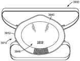
다른 태양에서, 본 개시는 착용자의 귀를 덮도록 형상화된 2개의 이어 컵(ear cup) 및 각각의 이어 컵의 주변부(periphery)를 따라 고정된 밀봉 링(sealing ring)을 포함하는 청각 보호기를 제공한다. 밀봉 링은 중합체 리본 및 중합체 스트랜드를 포함하는 중합체 네팅을 포함하며, 중합체 리본 및 스트랜드 각각은 길이, 폭, 및 높이를 가지며, 여기서 길이는 최장 치수이고, 폭은 최단 치수이며, 높이는 길이와 폭에 대해 가로지르는 치수이다. 중합체 리본은 적어도 5:1의 높이-대-폭 종횡비, 단지 하나의 중합체 스트랜드에만 단속적으로 접합되는 주 표면, 및 하나의 중합체 스트랜드의 높이보다 적어도 2배 더 큰 높이를 갖는다.In another aspect, the disclosure provides an ear protector including two ear cups configured to cover the wearer's ear and a sealing ring secured along the periphery of each ear cup. do. The sealing ring comprises a polymeric netting comprising a polymeric ribbon and a polymeric strand, wherein each of the polymeric ribbon and the strand has a length, a width and a height, wherein the length is the longest dimension, the width is the shortest dimension, . The polymeric ribbon has a height-to-width aspect ratio of at least 5: 1, a major surface that is intermittently bonded to only one polymeric strand, and a height that is at least two times greater than the height of one polymeric strand.
본 명세서에 제공된 모든 표제는 독자의 편의를 위한 것이고, 표제 다음에 이어지는 임의의 문장의 의미를 제한하는 데 사용되어서는 안된다 - 그렇게 명시되지 않는 한 -.All headings provided herein are for the convenience of the reader and should not be used to limit the meaning of any sentence following the heading - unless so specified.
용어 "포함한다" 및 그의 변형은 이들 용어가 '발명을 실시하기 위한 구체적인 내용' 및 '청구범위'에서 나타날 경우 제한적 의미를 갖지 않는다. 그러한 용어는 언급된 단계 또는 요소 또는 단계들 또는 요소들의 그룹을 포함하지만, 임의의 다른 단계 또는 요소 또는 단계들 또는 요소들의 그룹을 배제하지 않음을 암시하는 것으로 이해될 것이다. 용어 "~로 이루어지는"은 어구 "~로 이루어지는" 앞에 오는 것은 무엇이든 그것을 "포괄"하며 그것으로 제한됨을 의미한다. 따라서, 어구 "~로 이루어지는"은 열거된 요소들이 필요하거나 필수적이고, 다른 요소들이 존재하지 않을 수 있음을 나타낸다. 용어 "~로 본질적으로 이루어지는"은 그 어구 앞에 열거된 임의의 요소를 포함하며, 열거된 요소에 대해 본 개시에 명시된 움직임 또는 동작을 방해하거나 그것에 기여하지 않는 다른 요소로 제한됨을 의미한다. 따라서, 어구 "~로 본질적으로 이루어지는"은 열거된 요소가 필요하거나 필수적이지만, 다른 요소가 임의적이고, 그것이 열거된 요소의 움직임 또는 동작에 실질적으로 영향을 미치는지 여부에 따라 존재할 수 있거나 존재하지 않을 수 있음을 나타낸다.The term " comprises "and variations thereof are not meant to be limiting when the terms appear in the Detailed Description and Claims. It is to be understood that such term encompasses the stated step or element or group of steps or elements but does not exclude any other step or element or step or group of elements. The term "consisting of" means that it is "encompassed" and limited to whatever comes before the "consisting of". Thus, the phrase "consisting of" indicates that the listed elements are necessary or necessary, and that other elements may not be present. The term "consisting essentially of" includes any element listed before the phrase and means that the listed element is limited to other elements that do not interfere with or contribute to the motion or motion specified in this disclosure. Thus, the phrase "consisting essentially of" means that the listed element is necessary or necessary, but may or may not exist depending on whether the other element is arbitrary and whether it substantially affects the motion or behavior of the listed element .
단어 "바람직한" 및 "바람직하게는"은 소정 상황하에서 소정 이득을 제공할 수 있는 본 개시의 실시예를 지칭하지만; 동일하거나 다른 상황하에서 다른 실시예가 또한 바람직할 수 있다. 나아가, 하나 이상의 바람직한 실시예의 언급은 다른 실시예가 유용하지 않다는 것을 암시하지 않으며, 다른 실시예를 본 개시의 범주로부터 배제하도록 의도되지 않는다.The words "preferred" and "preferably" refer to embodiments of the present disclosure which may provide certain gains under certain circumstances; Other embodiments may also be desirable under the same or different circumstances. Further, the mention of one or more preferred embodiments does not imply that other embodiments are not useful, and is not intended to exclude other embodiments from the scope of this disclosure.
본 출원에서, 부정관사("a", "an") 및 정관사("the")와 같은 용어는 단수 엔티티(entity)만을 지칭하도록 의도되는 것이 아니라, 일반적인 부류를 포함하며, 그의 구체적인 예가 예시를 위해 사용될 수 있다. 용어 부정관사("a", "an") 및 정관사("the")는 용어 "적어도 하나"와 상호교환적으로 사용된다. 목록에 뒤따르는 어구 "~ 중 적어도 하나" 및 "~ 중 적어도 하나를 포함한다"는 목록 내의 항목들 중 임의의 하나, 및 목록 내의 2개 이상의 항목들의 임의의 조합을 지칭한다.In this application, terms such as "a", "an" and "the" are intended to refer not only to singular entities, but also to a general class, Lt; / RTI > The terms "a", "an", and "the" are used interchangeably with the term "at least one". The phrase " include at least one of "and" includes at least one of "refers to any one of the items in the list and any combination of two or more items in the list.
목록에 뒤따르는 어구 "~ 중 적어도 하나" 및 "~ 중 적어도 하나를 포함한다"는 목록 내의 항목들 중 임의의 하나, 및 목록 내의 2개 이상의 항목들의 임의의 조합을 지칭한다.The phrase " include at least one of "and" includes at least one of "refers to any one of the items in the list and any combination of two or more items in the list.
본 명세서에 사용되는 바와 같이, 용어 "또는"은 일반적으로 "및/또는"을 포함하는 그의 통상적인 의미로 사용된다 - 내용이 명백하게 달리 지시하지 않는 한 -.As used herein, the term "or" is generally used in its ordinary sense to include "and / or" unless the context clearly dictates otherwise.
용어 "및/또는"은 열거된 요소들 중 하나 또는 모두, 또는 열거된 요소들 중 임의의 2개 이상 요소의 조합을 의미한다.The term "and / or" means one or all of the listed elements, or any combination of two or more of the listed elements.
또한 본 명세서에서, 모든 숫자는 용어 "약"에 의해, 그리고 바람직하게는 용어 "정확하게는"에 의해 수식되는 것으로 가정된다. 측정량과 관련하여 본 명세서에 사용되는 바와 같이, 용어 "약"은 측정을 실시하고 그 측정의 목적 및 사용되는 측정 장비의 정확도에 상응하여 소정 수준의 주의를 기울이는 당업자에 의해 예측될 바와 같은 측정량에 있어서의 변동을 지칭한다. 본 명세서에서, "최대" 숫자(예를 들어, 최대 50)는 그 숫자(예를 들어, 50)를 포함한다.Also, in this specification, all numbers are assumed to be modified by the term " about "and preferably by the term" exactly. &Quot; The term "about" as used herein in reference to a measurand refers to a measurement as performed by a person skilled in the art to perform a measurement and to pay a certain amount of attention in accordance with the purpose of the measurement and the accuracy of the measurement equipment being used Quot; refers to the variation in the amount of the liquid. In this specification, a "maximum" number (e.g., a maximum of 50) includes that number (e.g., 50).
또한 본 명세서에서, 종점(endpoint)에 의한 수치 범위의 언급은 그 종점뿐만 아니라 그 범위 내에 포함되는 모든 수를 포함한다(예를 들어, 1 내지 5는 1, 1.5, 2, 2.75, 3, 3.80, 4, 5 등을 포함한다).Also, in this specification, reference to a numerical range by an endpoint includes all numbers contained within that range as well as its endpoint (e.g., 1 to 5 are 1, 1.5, 2, 2.75, 3, 3.80 , 4, 5, etc.).
용어Terms
본 명세서에 기재된 용어는 다음과 같이 정의된 의미를 가질 것이다:The terms described herein will have the following defined meanings:
"마스크 본체의 주연부의 적어도 일부분에 인접한"은 요소 또는 장치가 마스크 본체의 중심 영역 또는 부분보다 마스크 본체의 주연부의 적어도 일부분에 더 가깝게 배치됨을 의미한다;Means that the element or device adjacent "at least a portion of the periphery of the mask body " is disposed closer to at least a portion of the periphery of the mask body than the central region or portion of the mask body;
"청정 공기"는 오염물을 제거하도록 여과된 다량의 대기 중의 주위 공기를 의미한다;"Clean air" means a large amount of ambient air in the atmosphere filtered to remove contaminants;
"오염물"은 입자(먼지, 미스트 및 연무를 포함함), 및/또는 일반적으로 입자인 것으로 간주되지 않을 수 있지만(예컨대, 유기 증기 등) 공기 중에 떠 있을 수 있는 다른 물질을 의미한다;"Contaminant" means particles (including dust, mist, and mist), and / or other materials that may not normally be considered particles, but which may float in the air (e.g., organic vapor, etc.);
"가로방향 치수(crosswise dimension)"는 호흡기를 전방으로부터 볼 때 좌우로 호흡기를 가로질러 측방향으로 연장되는 치수이다;A "crosswise dimension" is a dimension that extends laterally across the respirator from left to right as viewed from the front of the respirator;
"컵-형상의 구성" 및 그의 변형은 사람의 코 및 입을 적절히 덮을 수 있는 임의의 용기-유형 형상을 의미한다;"Cup-shaped configuration" and its modifications mean any container-type configuration that can adequately cover the nose and mouth of a person;
하니스의 스트랩에 관하여 "탄성적"은 스트랩에 손상을 주지 않고서 적어도 100%만큼 연신되고 본질적으로 원래 치수로 복귀할 수 있음을 의미한다;"Elastic" with respect to the strap of the harness means that it can be stretched by at least 100% and return essentially to its original dimension without damaging the strap;
"외부 기체 공간"은 호기된 기체가 마스크 본체 및/또는 호기 밸브를 통해 이를 지나 통과한 후에 진입하는 주위 대기 기체 공간을 의미한다;"External gas space" means an ambient atmospheric gas space into which exhaled gases enter after passing through the mask body and / or exhalation valve;
"외부 표면"은 마스크 본체가 사람의 안면 상에 위치된 때 주위 대기 기체 공간에 노출되는 마스크 본체의 표면을 의미한다;"Outer surface" refers to the surface of the mask body that is exposed to ambient atmospheric gas space when the mask body is placed on the face of a person;
"안면 시일"은 그렇지 않을 경우 마스크 본체가 안면과 접촉할 하나 이상의 위치에서 마스크 본체와 착용자의 안면 사이에 위치되는 부품(들)을 의미한다;"Face seal" means the part (s) located between the mask body and the wearer's face at one or more locations where the mask body will otherwise contact the face;
"안면부 여과식"은 마스크 본체 그 자체가 그것을 통과하는 공기를 여과하도록 설계되고; 이러한 목적을 달성하기 위해 마스크 본체에 부착되거나 그것 내에 성형된 별도로 식별가능한 필터 카트리지 또는 삽입-성형된 필터 요소가 존재하지 않음을 의미한다;"Facial filtration" means that the mask body itself is designed to filter the air through it; Means that there is no separately identifiable filter cartridge or insert-molded filter element attached to or shaped within the mask body to accomplish this purpose;
"필터" 또는 "여과 층"은 공기-투과성 재료의 하나의 층을 의미하며, 이러한 층(들)은 그것을 통과하는 공기 스트림으로부터 (입자와 같은) 오염물을 제거하는 주된 목적을 위해 구성된다;"Filter" or "filtration layer" means one layer of air-permeable material, such layer (s) being configured for the main purpose of removing contaminants (such as particles) from the air stream passing therethrough;
"필터 매체"는 그것을 통과하는 공기로부터 오염물을 제거하도록 설계된 공기-투과성 구조물을 의미한다;"Filter media" means an air-permeable structure designed to remove contaminants from the air passing therethrough;
"여과 구조물"은 공기를 여과하는 일반적으로 공기-투과성인 구조물을 의미한다;"Filtering structure" means a structure that is generally air-permeable to filter air;
"내향으로 절첩된"은 그것으로부터 연장되는 부분을 향해 다시 구부러지는 것을 의미한다;"Inwardly folded" means bent again toward the portion extending from it;
"하니스"는 마스크 본체를 착용자의 안면 상에 지지하는 것을 보조하는 구조물 또는 부품들의 조합을 의미한다;"Harness" means a structure or combination of parts that assists in supporting the mask body on the wearer ' s face;
"내부 기체 공간"은 마스크 본체와 착용자의 안면 사이의 공간을 의미한다;"Inner gas space" means the space between the mask body and the wearer's face;
"내부 표면"은 마스크 본체가 착용자의 안면 상에 위치된 때 착용자의 안면에 가장 가까운 마스크 본체의 표면을 의미한다;"Inner surface" means the surface of the mask body closest to the wearer's face when the mask body is placed on the wearer's face;
"~에 결합된"은 직접적으로 또는 간접적으로 고정되는 것을 의미한다;"Coupled to" means being fixed, either directly or indirectly;
"경계선"은 절첩부, 시임, 용접선, 접합선, 봉제선, 힌지선, 및/또는 이들의 임의의 조합을 의미한다;"Boundary line" means folds, seams, weld lines, joining lines, sewing lines, hinge lines, and / or any combination thereof;
"마스크 본체"는, 착용자의 코 및 입 위에 맞춰지도록 설계되고, 외부 기체 공간으로부터 분리된 내부 기체 공간을 한정하는 데 도움을 주는 공기-투과성 구조물을 의미한다(층들 및 그것의 부분들을 함께 결합하는 시임 및 접합부를 포함함);"Mask body" means an air-permeable structure that is designed to fit over the wearer's nose and mouth, and that helps to define an internal gas space separated from the external gas space Seams and joints);
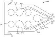
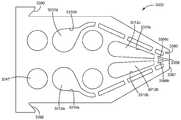
"네팅"은 네팅의 스트랜드와 리본 사이의 개방부 또는 공간에 의해 개방부가 형성된 오픈워크 구조체를 의미한다;"Netting" means an openwork structure having an opening formed by the opening or space between the strand of the netting and the ribbon;
"코 클립"은 적어도 착용자의 코 주위에서 밀봉을 개선하기 위해 마스크 본체 상에 사용하도록 구성된 (코 발포체(nose foam) 이외의) 기계적 장치를 의미한다;"Nose clip" means a mechanical device (other than nose foam) adapted for use on the mask body to improve sealing around at least the wearer's nose;
"오픈워크"는 공기가 그것을 쉽게 통과하기에 그리고 사람이 육안으로(즉, 기구의 도움 없이) 그것을 통해 보기에 충분히 크도록 크기설정된 개방 공간을 갖는 것을 의미한다;"Openwork" means that the air has an open space that is large enough to pass it easily and to be large enough to be seen by the human eye (ie, without the aid of an instrument) through it;
"주연부"는 호흡기가 사람에 의해 착용되고 있을 때 착용자의 안면에 대체로 근접하게 배치될 마스크 본체의 외측 에지를 의미하고; "주연부 세그먼트(perimeter segment)"는 주연부의 일부분이다;"Peripheral" means the outer edge of the mask body to be placed generally close to the wearer's face when the respirator is being worn by a person; The "perimeter segment" is part of the periphery;
"주름(pleat)"은 그 자신 상으로 다시 절첩되도록 설계되거나 그렇게 절첩된 부분을 의미한다;"Pleat" means a portion designed or otherwise folded back onto itself;
"중합체" 및 "플라스틱"은 각각, 하나 이상의 중합체를 주로 포함하고 다른 성분을 또한 함유할 수 있는 재료를 의미한다;"Polymer" and "plastics" refer to materials, respectively, that comprise primarily one or more polymers and may also contain other components;
"호흡기"는 착용자에게 호흡할 청정 공기를 제공하기 위해 사람에 의해 착용되는 공기 여과 장치를 의미한다;"Respiratory" means an air filtration device that is worn by a person to provide clean air to the wearer;
"리본"은 대체로 직사각형 또는 장방형인 단면을 갖는 중합체 네팅 내의 종방향으로 연장되는 요소를 지칭한다. 적어도 3:1, 적어도 5:1, 또는 적어도 7:1의 높이-대-폭 종횡비를 갖는 것 이외의 리본이 본 명세서에 개시된 중합체 네팅 내에 있을 수 있다. 바꾸어 말하면, 직사각형 단면을 갖는 중합체 네팅 내의 모든 요소가 적어도 3:1, 적어도 5:1, 적어도 7:1 등의 높이-대-폭 종횡비를 갖도록 요구되지는 않는다. 중합체 스트랜드가 또한 직사각형 단면을 가질 수 있다. 중합체 리본의 주 표면은 리본의 높이 및 길이에 의해 한정되는 표면이다;"Ribbon" refers to a longitudinally extending element in a polymer netting having a generally rectangular or rectangular cross-section. Ribbits other than those having a height-to-width aspect ratio of at least 3: 1, at least 5: 1, or at least 7: 1 may be present in the polymer netting disclosed herein. In other words, not all elements in a polymer netting having a rectangular cross section are required to have a height-to-width aspect ratio of at least 3: 1, at least 5: 1, at least 7: The polymeric strand may also have a rectangular cross-section. The major surface of the polymer ribbon is a surface defined by the height and length of the ribbon;
"측부"는 마스크 본체가 직립 위치로 배향되고 전방으로부터 볼 때 마스크 본체를 중심에서 그리고 수직으로 양분하는 평면으로부터 멀리 떨어진 마스크 본체 상의 영역을 의미한다;"Side" means an area on the mask body that is oriented away from a plane bisecting the mask body vertically and vertically when viewed from the front, with the mask body oriented in the upright position;
"부비동 영역"은 호흡기가 적절한 구성으로 착용되고 있을 때 착용자의 눈 및/또는 안와(eye orbital) 아래에 존재하는 마스크 본체의 부분 또는 영역과 코 영역을 의미한다;"Sinus area" means a portion or area of the mask body and nose area present under the wearer ' s eyes and / or eye orbital when the respirator is being worn in a suitable configuration;
"꼭 맞는 맞춤" 또는 "꼭 맞게 맞춰지다"는 본질적으로 기밀(air-tight)(또는 실질적으로 누설이 없는) 맞춤이 (마스크 본체와 착용자의 안면 사이에) 제공되는 것을 의미한다;"Fit fit" or "fit to fit" means that an essentially air-tight (or substantially non-leaky) fit is provided (between the mask body and the wearer's face);
"스트랩"은 대체로 평평한 기다란(elongated) 구조체를 의미한다; 그리고"Strap" means a generally flat elongated structure; And
"횡방향으로 연장되는"은 대체로 가로방향 치수로 연장되는 것을 의미한다."Extending laterally" means extending generally in the transverse dimension.
본 개시의 이들 및 다른 태양이 본 명세서의 상세한 설명으로부터 명백할 것이다. 그러나, 어떠한 경우에도, 상기의 개요는 청구된 주제에 대한 제한으로서 해석되어서는 안되며, 그 주제는 절차 수행 동안 보정될 수 있는 바와 같은 첨부된 청구범위에 의해서만 한정된다.These and other aspects of the disclosure will be apparent from the detailed description herein. In any case, however, the above summary is not to be construed as a limitation on the claimed subject matter, which subject matter is limited only by the appended claims as may be amended during the course of the proceedings.
명세서 전체에 걸쳐, 첨부 도면을 참조하며, 첨부 도면에서 동일한 도면 부호는 동일한 요소를 지시한다.
도 1은 본 개시에 따른 중합체 네팅의 실시예의 측단면도.
도 2는 본 개시에 따른 중합체 네팅의 실시예의 사시도.
도 3은 중합체 네팅이 흡수 구성요소와 같은 기재(substrate)에 결합된, 본 개시에 따른 중합체 네팅의 다른 실시예의 평면의 개략 단면도.
도 4는 본 개시에 따른 중합체 네팅의 또 다른 실시예의 평면의 개략 단면도.
도 5는 본 개시에 따른 중합체 네팅의 또 다른 실시예의 평면의 개략 단면도.
도 6은 본 개시에 따른 중합체 네팅의 또 다른 실시예의 평면의 개략 단면도.
도 7은 본 개시에 따른 중합체 네팅의 또 다른 실시예의 평면의 개략 단면도.
도 8은 본 개시에 따른 중합체 네팅의 또 다른 실시예의 평면의 개략 단면도.
도 9는 예를 들어 도 1 내지 도 4에 도시된 바와 같은 중합체 네팅을 형성할 수 있는 심들의 배열(sequence of shims)에 적합한 심의 실시예의 평면도.
도 10은 예를 들어 도 1 내지 도 7에 도시된 바와 같은 중합체 네팅을 형성할 수 있는 심들의 배열에 적합한 심의 다른 실시예의 평면도.
도 11은 예를 들어 도 1 내지 도 4에 도시된 바와 같은 중합체 네팅을 형성할 수 있는 심들의 배열에 적합한 심의 다른 실시예의 평면도.
도 12a는 도 1에 도시된 바와 같은 중합체 네팅의 일부를 형성하도록 구성된 도 9 내지 도 11의 심을 채용한, 심들의 배열의 사시 조립도.
도 12b는 도 12a에 "12b"로 참조 표시된 섹션의 확대도.
도 13은 예를 들어 도 5에 도시된 바와 같은 중합체 네팅을 형성할 수 있는 심들의 배열에 적합한 심의 실시예의 평면도.
도 14는 예를 들어 도 5에 도시된 바와 같은 중합체 네팅을 형성할 수 있는 심들의 배열에 적합한 심의 다른 실시예의 평면도.
도 15a는 도 5에 도시된 바와 같은 중합체 네팅의 일부를 형성하도록 구성된 도 10과 도 13 및 도 14의 심을 채용한, 심들의 배열의 사시 조립도.
도 15b는 도 15a에 "15b"로 참조 표시된 섹션의 확대도.
도 16은 예를 들어 도 6에 도시된 바와 같은 중합체 네팅을 형성할 수 있는 심들의 배열에 적합한 심의 실시예의 평면도.
도 17은 예를 들어 도 6에 도시된 바와 같은 중합체 네팅을 형성할 수 있는 심들의 배열에 적합한 심의 다른 실시예의 평면도.
도 18a는 도 6에 도시된 바와 같은 중합체 네팅의 일부를 형성하도록 구성된 도 10 및 도 11과 도 16 및 도 17의 심을 채용한, 심들의 배열의 사시 조립도.
도 18b는 도 18a에 "18b"로 참조 표시된 섹션의 확대도.
도 19는 예를 들어 도 7에 도시된 바와 같은 중합체 네팅을 형성할 수 있는 심들의 배열에 적합한 심의 실시예의 평면도.
도 20은 예를 들어 도 7에 도시된 바와 같은 중합체 네팅을 형성할 수 있는 심들의 배열에 적합한 심의 다른 실시예의 평면도.
도 21a는 도 7에 도시된 바와 같은 중합체 네팅의 일부를 형성하도록 구성된 도 10, 도 14와 도 19 및 도 20의 심을 채용한, 심들의 배열의 사시 조립도.
도 21b는 도 21a에 "21b"로 참조 표시된 섹션의 확대도.
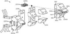
도 22는 도 12a, 도 15a, 도 18a, 도 21a, 또는 도 27a에 도시된 심들의 배열의 다수의 반복으로 구성된 압출 다이에 적합한 마운트(mount)의 예의 분해 사시도.
도 23은 조립된 상태에 있는 도 22의 마운트의 사시도.
도 24는 예를 들어 도 8에 도시된 바와 같은 중합체 네팅을 제조하는 데 유용한 심들의 배열을 형성하기에 적합한 심의 실시예의 평면도.
도 25는 예를 들어 도 8에 도시된 바와 같은 중합체 네팅을 제조하는 데 유용한 심들의 배열을 형성하기에 적합한 심의 다른 실시예의 평면도.
도 26은 예를 들어 도 8에 도시된 바와 같은 중합체 네팅에 유용한 심들의 배열을 형성하기에 적합한 심의 또 다른 실시예의 평면도.
도 27a는 예를 들어 도 8에 도시된 바와 같은 중합체 네팅의 일부를 형성하도록 구성된 도 24 내지 도 26의 심을 채용한, 심들의 배열의 사시도.
도 27b는 도 27a에 "27b"로 참조 표시된 섹션의 확대도.
도 28은 본 개시에 따른 흡수 용품의 예의 개략 분해도.
도 29는 랩(wrap)으로서 사용되는 본 개시에 따른 중합체 네팅의 실시예를 보여주는 발의 사시도.
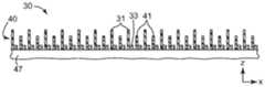
도 30은 예 1의 중합체 네팅의 평면도의 사진.
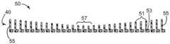
도 31a와 도 31b는 예 2의 중합체 네팅의, 각각, 평면도와 측면도의 사진.
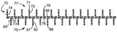
도 32a와 도 32b는 예 3의 중합체 네팅의, 각각, 평면도와 측면도의 사진.
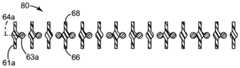
도 33a와 도 33b는 예 4의 중합체 네팅의, 각각, 평면도와 측면도의 사진.
도 34a와 도 34b는 예 6의 중합체 네팅의, 각각, 평면도와 측면도의 사진.
도 35는 예 1, 예 1b, 예 4a, 예 4b, 예 6a, 및 예 6b에 대한 유체 스트라이크-스루 시간(fluid strike-through time)을 평가하는 데 사용되는 시험 지그(test jig)의 사진.
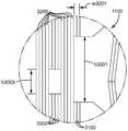
도 36은 호흡기의 일 실시예의 개략 정면도.
도 37은 호흡기의 다른 실시예의 개략 배면도.
도 38은 호흡기의 다른 실시예의 개략 배면도.
도 39는 호흡기의 다른 실시예의 개략 배면도.
도 40은 호흡기의 여과 구조물의 일 실시예의 개략 단면도.
도 41은 청각 보호기의 일 실시예의 개략 평면도.
도 42는 도 41의 청각 보호기의 개략 단면도.
도 43은 폴리우레탄 에스테르 발포체 및 폴리우레탄 발포체와 비교한 중합체 네팅의 여러 가지 예에 대한 퍼센트 변형률(percent strain) 대 시간의 그래프.Throughout the description, reference is made to the accompanying drawings, in which like reference numerals designate like elements.
1 is a side cross-sectional view of an embodiment of a polymer netting according to the present disclosure;
2 is a perspective view of an embodiment of a polymer netting in accordance with the present disclosure;
3 is a schematic cross-sectional view of a plane of another embodiment of a polymer netting according to this disclosure, wherein the polymer netting is bonded to a substrate such as an absorbent component.
4 is a schematic cross-sectional view of a plane of another embodiment of a polymer netting in accordance with the present disclosure;
5 is a schematic cross-sectional view of a plane of another embodiment of a polymer netting in accordance with the present disclosure;
6 is a schematic cross-sectional view of a plane of another embodiment of a polymer netting in accordance with the present disclosure;
7 is a schematic cross-sectional view of a plane of another embodiment of a polymer netting in accordance with the present disclosure;
8 is a schematic cross-sectional view of a plane of another embodiment of a polymer netting in accordance with the present disclosure;
9 is a plan view of an embodiment of a shim suitable for a sequence of shims capable of forming a polymer netting as shown, for example, in Figs. 1-4. Fig.
10 is a plan view of another embodiment of a shim suitable for arranging shims that may form a polymer netting as shown, for example, in Figs. 1-7.
Figure 11 is a plan view of another embodiment of a shim suitable for arranging shims that may form a polymer netting as shown in Figures 1-4, for example.
12A is a perspective assembly view of an arrangement of shims employing shims of Figs. 9-11 configured to form a portion of a polymer netting as shown in Fig.
Fig. 12B is an enlarged view of a section referred to as " 12b "in Fig. 12A.
Figure 13 is a plan view of an embodiment of a shim suitable for arranging shims that may form a polymer netting as shown in Figure 5, for example.
Figure 14 is a plan view of another embodiment of a shim suitable for arranging shims that may form a polymer netting as shown in Figure 5, for example.
15A is a perspective assembly view of an arrangement of shims employing shims of Figs. 10, 13 and 14 configured to form a portion of the polymer netting as shown in Fig.
15B is an enlarged view of a section referred to as "15b" in Fig.
Figure 16 is a plan view of an embodiment of the shim, which is suitable for arranging the shims capable of forming a polymer netting, for example, as shown in Figure 6;
Figure 17 is a plan view of another embodiment of a shim suitable for arranging shims that may form a polymer netting, for example, as shown in Figure 6;
18A is a perspective assembly view of an arrangement of shims employing shims of Figs. 10 and 11 and Figs. 16 and 17 configured to form part of a polymer netting as shown in Fig.
Figure 18b is an enlarged view of the section referenced "18b" in Figure 18a.
19 is a plan view of an embodiment of the shim, which is suitable for arranging shims that may form a polymer netting as shown, for example, in Fig.
Figure 20 is a plan view of another embodiment of a shim suitable for arranging shims that may form a polymer netting as shown in Figure 7, for example.
21A is a perspective assembly view of an arrangement of shims employing shims of Figs. 10, 14, 19, and 20 configured to form a portion of a polymer netting as shown in Fig.
Fig. 21B is an enlarged view of a section referred to as "21b " in Fig.
Figure 22 is an exploded perspective view of an example of a suitable mount for an extrusion die comprising a plurality of repetitions of the arrangement of shims shown in Figures 12a, 15a, 18a, 21a, or 27a.
Figure 23 is a perspective view of the mount of Figure 22 in an assembled state.
24 is a plan view of an embodiment of a shim suitable for forming an array of shims useful for producing polymer netting, for example as shown in Fig.
25 is a plan view of another embodiment of a shim suitable for forming an array of shims useful for producing polymer netting as shown, for example, in Fig.
26 is a plan view of another embodiment of a shim suitable for forming an array of shims useful for polymer netting as shown, for example, in Fig.
27A is a perspective view of an arrangement of shims employing the shims of FIGS. 24-26 configured to form a portion of a polymer netting as shown in FIG. 8, for example. FIG.
27B is an enlarged view of the section referred to in Fig. 27A as "27b ".
28 is a schematic exploded view of an example of an absorbent article according to the present disclosure;
29 is a perspective view of a foot showing an embodiment of polymer netting according to the present disclosure used as a wrap.
30 is a photograph of a top view of the polymer netting of Example 1. Fig.
Figs. 31A and 31B are photographs of a plan view and a side view, respectively, of the polymer netting of Example 2. Fig.
32A and 32B are photographs of a plan view and a side view, respectively, of the polymer netting of Example 3;
33A and 33B are photographs of a plan view and a side view, respectively, of the polymer netting of Example 4;
34A and 34B are photographs of the polymer netting of Example 6, respectively, in plan and side views.
35 is a photograph of a test jig used to evaluate the fluid strike-through time for Example 1, Example 1b, Example 4a, Example 4b, Example 6a, and Example 6b.
36 is a schematic front view of an embodiment of a respirator;
Figure 37 is a schematic rear view of another embodiment of a respirator.
38 is a schematic rear view of another embodiment of a respirator.
39 is a schematic rear view of another embodiment of a respirator.
40 is a schematic cross-sectional view of one embodiment of a filtration structure of a respirator;
41 is a schematic plan view of one embodiment of a hearing protector;
42 is a schematic cross-sectional view of the auditory protector of FIG. 41;
Figure 43 is a graph of percent strain versus time for various examples of polymer netting compared to polyurethane ester foams and polyurethane foams.
일반적으로, 본 개시는 중합체 네팅을 포함하는 호흡기의 하나 이상의 실시예를 제공한다. 하나 이상의 실시예에서, 중합체 네팅은 호흡기용 하니스를 위한 스트랩으로서 사용되거나 포함될 수 있다. 또한, 하나 이상의 실시예에서, 중합체 네팅은 또한 호흡기의 마스크 본체의 주연부에 인접하게 배치될 수 있는 안면 시일에 사용될 수 있다. 그리고, 하나 이상의 실시예에서, 중합체 네팅은 또한 호흡기의 커버 웨브로서 사용될 수 있다. 또한, 하나 이상의 실시예에서, 중합체 네팅은 청각 보호기에 사용될 수 있다.Generally, the present disclosure provides one or more embodiments of a respirator that includes polymer netting. In at least one embodiment, the polymer netting may be used or included as a strap for a respiratory harness. Further, in at least one embodiment, the polymer netting may also be used in a face seal that may be disposed adjacent the periphery of the respirator's mask body. And, in at least one embodiment, the polymer netting can also be used as a cover web of a respirator. Further, in at least one embodiment, polymer netting may be used in hearing protectors.
본 개시의 호흡기는 마스크 본체와 마스크 본체에 부착된 하니스를 포함할 수 있다. 하나 이상의 실시예에서, 하니스는 마스크 본체의 서로 반대편에 있는 측부들에서 마스크 본체에 결합된 하나 이상의 스트랩을 포함할 수 있다. 또한, 하나 이상의 스트랩은 본 명세서에 추가로 기술되는 바와 같은 중합체 네팅을 포함할 수 있다. 중합체 네팅은 스트랩이 착용자에게 더 편안하도록 공기가 스트랩을 통해 유동하도록 허용할 수 있다. 또한, 하나 이상의 실시예에서, 스트랩은 그렇지 않을 경우 스트랩과 착용자의 머리 사이에 포획될 습기 또는 땀이 머리로부터 멀어지는 쪽으로 수송되도록 허용하여, 착용자에게 추가의 편안함을 제공할 수 있다.The respirator of the present disclosure may include a mask body and a harness attached to the mask body. In at least one embodiment, the harness may include one or more straps coupled to the mask body at sides opposite to each other of the mask body. In addition, the one or more straps may comprise a polymer netting as further described herein. The polymer netting may allow air to flow through the strap to make the strap more comfortable to the wearer. Further, in at least one embodiment, the strap may allow moisture or sweat to be trapped between the strap and the wearer's head, if not otherwise, to be transported away from the head, thereby providing additional comfort to the wearer.
호흡기와 함께 흔히 사용되는 스트랩은 전형적으로 브레이딩된 헤드밴드 또는 크레이튼 고무와 같은 탄성중합체 재료를 포함한다. 예컨대, 쉬에의 미국 특허 제6,332,465호, 디브 등의 WO 9831743호, 및 브라이언트 등의 WO9732493 A1호를 참조한다. 이들 스트랩은 전형적으로 외양이 중실형인데, 즉 부분적으로 또는 완전히 스트랩을 통해 볼 수 없다. 알려진 스트랩의 중실형 특성은 전체 제품 중량을 증가시킬 수 있고, 착용자의 목 상에서의 열 정체(heat retention)를 증가시킬 수 있다. 또한, 종래의 호흡기 스트랩은 스트랩이 전체에 걸쳐 하나의 색을 나타내도록 구성된다. 따라서, 양쪽 주 스트랩 표면이 동일한 외양을 갖는다. 그렇기 때문에, 스트랩이 꼬이는지를 알아차리기 어려울 수 있다. 스트랩은 또한 하나 초과의 색을 나타냄으로써 미적으로 다채롭거나 예술적으로 만족스러울 임의의 기회를 박탈당한다.Straps commonly used with respirators typically include an elastomeric material such as a braided headband or a creped rubber. See, for example, U.S. Patent No. 6,332,465 to Shie, WO 9831743 to Dib et al, and WO9732493A1 to Bryant et al. These straps are typically solid in appearance, that is, partially or completely not visible through the strap. The solid features of the known straps can increase the overall product weight and increase the heat retention on the wearer's neck. In addition, conventional respirator straps are configured so that the straps represent one color throughout. Thus, both main strap surfaces have the same appearance. Therefore, it can be difficult to notice whether the strap is twisted. The strap is also deprived of any opportunity to be aesthetically pleasing or artistically satisfactory by displaying more than one color.
하나 이상의 실시예에서, 하니스의 하나 이상의 스트랩을 형성하거나 그것에 사용되는 중합체 네팅은 중합체 리본과 중합체 스트랜드를 포함할 수 있다. 중합체 리본 및 스트랜드 각각은 길이, 폭, 및 높이를 갖는다. 길이는 최장 치수이고, 폭은 최단 치수이며, 높이는 길이와 폭에 대해 가로지르는 치수이다. 또한, 하나 이상의 실시예에서, 중합체 리본은 적어도 5:1의 높이 대 폭 종횡비를 가질 수 있다. 하나 이상의 실시예에서, 각각의 중합체 리본의 주 표면이 단지 하나의 중합체 스트랜드에만 단속적으로 접합될 수 있다. 그리고, 하나 이상의 실시예에서, 중합체 리본의 높이가 중합체 스트랜드의 높이보다 적어도 2배 더 클 수 있다.In at least one embodiment, the polymer netting forming or forming one or more straps of the harness may comprise polymeric ribbons and polymeric strands. Each of the polymer ribbon and strand has a length, a width, and a height. The length is the longest dimension, the width is the shortest dimension, and the height is the dimension crossing the length and width. Further, in at least one embodiment, the polymeric ribbon may have a height to width aspect ratio of at least 5: 1. In at least one embodiment, the major surface of each polymeric ribbon may be intermittently bonded to only one polymeric strand. And, in at least one embodiment, the height of the polymeric ribbon can be at least two times greater than the height of the polymeric strand.
본 명세서에 기술된 호흡기의 하나 이상의 실시예는 호흡기의 마스크 본체의 주연부의 적어도 일부분에 인접하게 배치되는 안면 시일을 포함할 수 있다. 하나 이상의 실시예에서, 안면 시일은 본 명세서에 추가로 기술되는 바와 같은 중합체 네팅을 포함하거나 그것으로부터 구성될 수 있다. 그러한 안면 시일은 습기가 착용자의 안면으로부터 멀어지는 쪽으로 수송되도록 허용하여, 마스크를 착용자에게 더 편안하게 만들 수 있다.One or more embodiments of the respirator described herein may include a face seal disposed adjacent at least a portion of the periphery of the mask body of the respirator. In one or more embodiments, the face seal may comprise or be constructed from a polymer netting as further described herein. Such a face seal allows moisture to be transported away from the wearer ' s face, making the mask more comfortable for the wearer.
호흡기에 사용되는 보통의 안면 시일은 전형적으로 마스크 본체를 착용자의 안면에 대해 밀봉하는 데 도움을 주는 발포체 재료로 제조된다. 그러나, 그러한 발포체 재료는 착용자의 안면 상에 모인 습기가 안면으로부터 멀어지는 쪽으로 수송되는 것을 방해할 수 있다. 이러한 포획된 습기는 착용자의 피부를 자극하고 마스크를 불편하게 느끼게 만들 수 있다.Common face seals used in respirators are typically made of foam material that helps seal the mask body against the wearer's face. Such foam material, however, can prevent moisture collected on the wearer's face from being transported away from the face. Such trapped moisture can irritate the skin of the wearer and make the mask feel uncomfortable.
하나 이상의 실시예에서, 안면 시일을 형성하거나 그것에 포함되는 중합체 네팅은 중합체 리본과 중합체 스트랜드를 포함할 수 있다. 중합체 리본 및 스트랜드 각각은 길이, 폭, 및 높이를 갖는다. 길이는 최장 치수이고, 폭은 최단 치수이며, 높이는 길이와 폭에 대해 가로지르는 치수이다. 또한, 하나 이상의 실시예에서, 중합체 리본은 적어도 5:1의 높이 대 폭 종횡비를 가질 수 있다. 하나 이상의 실시예에서, 각각의 중합체 리본의 주 표면이 단지 하나의 중합체 스트랜드에만 단속적으로 접합될 수 있다. 그리고, 하나 이상의 실시예에서, 중합체 리본의 높이가 중합체 스트랜드의 높이보다 적어도 2배 더 클 수 있다.In at least one embodiment, the polymeric netting forming or forming a face seal can comprise polymeric ribbons and polymeric strands. Each of the polymer ribbon and strand has a length, a width, and a height. The length is the longest dimension, the width is the shortest dimension, and the height is the dimension crossing the length and width. Further, in at least one embodiment, the polymeric ribbon may have a height to width aspect ratio of at least 5: 1. In at least one embodiment, the major surface of each polymeric ribbon may be intermittently bonded to only one polymeric strand. And, in at least one embodiment, the height of the polymeric ribbon can be at least two times greater than the height of the polymeric strand.
또한, 하나 이상의 실시예에서, 본 명세서에 기술된 호흡기는 본 명세서에 추가로 기술되는 바와 같은 내측 커버 웨브 및 외측 커버 웨브 중 하나 또는 둘 모두를 포함할 수 있다. 하나 이상의 실시예에서, 내측 커버 웨브 및 외측 커버 웨브 중 하나 또는 둘 모두는 본 명세서에 추가로 기술되는 바와 같은 중합체 네팅을 포함하거나 그것으로부터 구성될 수 있다.Further, in one or more embodiments, the respirator described herein may include one or both of an inner cover web and an outer cover web as further described herein. In one or more embodiments, one or both of the inner cover web and the outer cover web may comprise or be constructed from a polymer netting as further described herein.
그리고, 하나 이상의 실시예에서, 본 명세서에 기술된 중합체 네팅은 청각 보호기의 이어 컵에 사용되는 밀봉 링을 형성하거나 구성하는 데 사용될 수 있다.And, in at least one embodiment, the polymer netting described herein can be used to form or configure the seal ring used in the ear cup of the hearing protector.
중합체 네팅Polymer netting
도 1은 예컨대 하니스의 스트랩, 안면 시일 등으로서 호흡기와 함께 사용될 수 있는 본 개시에 따른 중합체 네팅(10)의 실시예의 측면도를 예시한다. 중합체 네팅(10)은 중합체 리본(1) 및 중합체 스트랜드(3)를 포함한다. 중합체 리본(1) 및 중합체 스트랜드(3)는 각각 길이, 폭 "w1" 및 "w3", 및 높이 "h1" 및 "h3"을 갖는다. 중합체 리본(1) 및 스트랜드(3)의 길이는 최장 치수이고, 도 1에 도시되지 않는다. 길이는 최장 치수이고, 폭은 최단 치수이며, 높이는 길이와 폭에 대해 가로지르는 치수이다. 리본의 높이 "h1" 및 스트랜드의 높이 "h3"은 전형적으로, 각각, 각자의 길이와 폭 사이에 있다. 그러나, 스트랜드(3)는 또한 그것의 폭 "w3"과 실질적으로 동일한 높이 "h3"을 가질 수 있다. 원형 스트랜드의 경우, 높이 및 폭은 둘 모두 직경으로 지칭될 수 있다. 중합체 리본들 중 적어도 일부의 높이-대-폭 종횡비는 적어도 3:1이다. 몇몇 실시예에서, 중합체 리본들 중 적어도 일부의 높이-대-폭 종횡비는 적어도 5:1, 7:1, 8:1, 10:1, 11:1, 15:1, 20:1, 30:1, 또는 40:1이다. 중합체 리본의 높이는 대체로 중합체 스트랜드의 높이보다 크다. 하나 이상의 실시예에서, 중합체 리본들 각각의 높이는 단일 중합체 스트랜드의 높이보다 적어도 2배, 2.5배, 3배, 5배, 10배, 또는 20배 더 크다. 하나 이상의 실시예에서, 중합체 네팅(10)은 리본(1)들 중 하나 이상의 높이 h1과 스트랜드(3)들 중 하나 이상의 높이 h3 사이의 임의의 적합한 비를 포함할 수 있다. 하나 이상의 실시예에서, 비 h1 대 h3은 적어도 1:1, 2:1, 3:1, 4:1, 5:1, 6:1 등일 수 있다. 하나 이상의 실시예에서, 비 h1 대 h3은 100:1, 50:1, 10:1 등 이하일 수 있다.1 illustrates a side view of an embodiment of a polymeric netting 10 according to the present disclosure that may be used with a respirator as, for example, a strap, face seal, etc., of a harness. The polymer netting (10) comprises a polymer ribbon (1) and a polymeric strand (3). The
중합체 리본은 임의의 적합한 높이 h1을 가질 수 있다. 하나 이상의 실시예에서, 중합체 리본의 높이는 0.05 밀리미터 내지 10 밀리미터의 범위일 수 있다. 하나 이상의 실시예에서, 중합체 리본의 높이는 0.05 밀리미터 내지 3 밀리미터(mm)의 범위일 수 있다. 하나 이상의 실시예에서, 중합체 리본의 높이는 750 마이크로미터 초과이다. 하나 이상의 실시예에서, 중합체 리본의 높이는 1 cm 이하일 수 있다. 하나 이상의 실시예에서, 중합체 리본의 높이는 750 마이크로미터 초과 내지 3 mm(예컨대, 0.775 mm 내지 2 mm 또는 0.8 mm 내지 1.5 mm)의 범위이다. 하나 이상의 실시예에서, 중합체 리본 또는 중합체 스트랜드 중 적어도 하나의 높이는 750 마이크로미터 미만이다. 하나 이상의 실시예에서, 중합체 리본 또는 중합체 스트랜드 중 적어도 하나의 높이는 0.1 mm 내지 750 마이크로미터 미만(예컨대, 0.3 mm 내지 0.745 mm, 또는 0.5 mm 내지 0.745 mm)의 범위이다.The polymer ribbon may have any suitable height h1. In at least one embodiment, the height of the polymer ribbon may range from 0.05 millimeters to 10 millimeters. In at least one embodiment, the height of the polymer ribbon may range from 0.05 millimeters to 3 millimeters (mm). In at least one embodiment, the height of the polymer ribbon is greater than 750 micrometers. In at least one embodiment, the height of the polymer ribbon may be less than 1 cm. In at least one embodiment, the height of the polymer ribbon is in the range of more than 750 micrometers to 3 mm (e.g., 0.775 mm to 2 mm or 0.8 mm to 1.5 mm). In at least one embodiment, the height of at least one of the polymeric ribbon or polymeric strand is less than 750 micrometers. In at least one embodiment, the height of at least one of the polymeric ribbon or polymeric strands is in the range of 0.1 mm to less than 750 micrometers (e.g., 0.3 mm to 0.745 mm, or 0.5 mm to 0.745 mm).
도 2는 본 개시에 따른 중합체 네팅의 실시예의 사시도를 예시한다. 이 사시도에서, 중합체 리본 및 스트랜드의 길이 "l"이 관찰될 수 있다.Figure 2 illustrates a perspective view of an embodiment of a polymer netting according to the present disclosure. In this perspective, the length "1" of polymeric ribbon and strand can be observed.
다시 도 1 및 도 2를 참조하면, 중합체 리본(1, 11, 21)은 각각 단일 중합체 스트랜드(3, 13)에 단속적으로 결합된 제1 주 표면(2, 12)을 구비한다. 즉, 2개 이상의 중합체 스트랜드가 중합체 리본의 제1 주 표면에 결합되지 않는다. 중합체 리본의 제1 주 표면이 단일 중합체 스트랜드에 단속적으로 결합된다고 할 때, 중합체 스트랜드가 중합체 리본과, 중합체 스트랜드의 반대측에 있는 네팅의 다른 부분에 대한 접합 사이에서 요동하는 것을 알 수 있다. 도 2에 예시된 실시예에서, 2개의 인접한 중합체 리본(11, 21)이 2개의 인접한 중합체 리본(11, 21)에 적어도 부분적으로 교대로 접합된 단일 중합체 스트랜드(13)에 의해 함께 결합된다. 그러나, 이는 필요조건은 아니다. 예를 들어, 하나 이상의 실시예에서, 중합체 스트랜드는 중합체 리본과, 반드시 적어도 3:1의 높이-대-폭 종횡비를 갖지는 않는 비-요동 스트랜드에 대한 접합 사이에서 요동할 수 있다. 중합체 리본의 주 표면이 중합체 리본 및 네팅의 다른 스트랜드 또는 리본에 적어도 부분적으로 교대로 접합된 중합체 스트랜드에 단속적으로 접합되기 때문에, 중합체 리본은 전형적으로 중합체 스트랜드에 의해 교차되지 않는다. 본 명세서에 개시된 중합체 네팅의 실시예들 중 임의의 것에서, 중합체의 스트랜드와 리본은 전형적으로 중첩된(superimposed) 교차점 또는 개재된(interlaid) 교차점을 형성함으로써 실질적으로 서로 교차하지 않는다(예를 들어, 수를 기준으로 적어도 50(적어도 55, 60, 65, 70, 75, 80, 85, 90, 95, 99, 또는 심지어 100) 퍼센트가 서로 교차하지 않음).Referring again to Figures 1 and 2, the
도 1에서, 중합체 리본(1)들의 높이들 h1은 모두 대략 동일한 크기이고, 중합체 스트랜드(3)들의 높이들 h3은 모두 동일한 크기이지만, 도 2 내지 도 4에 도시된 바와 같이, 이는 필요조건은 아니다. 예를 들어, 도 3에 도시된 바와 같이 2가지 상이한 유형의 중합체 리본(31, 41)이 있을 수 있다. 중합체 리본(31)의 높이-대-폭 종횡비는 중합체 리본(41)의 높이-대-폭 종횡비보다 크다. 도 2 및 도 4에서, 중합체 리본(11, 21, 51)은 다양한 높이를 갖는다. 도 4에서, 중합체 리본(51)의 높이-대-폭 종횡비는 네팅의 중심(57)에서보다 중합체 네팅(50)의 에지(55)에서 더 크다. 이들 실시예에서, 중합체 리본(51)들 중 적어도 일부는 적어도 3:1의 높이-대-폭 종횡비를 갖는다.In Figure 1, the height h1 of the
도 1 내지 도 4에서 중합체 네팅 내의 다양한 중합체 리본과 중합체 스트랜드 사이의 간격이 대략 동일하지만, 이는 필요조건은 아니다. 임의의 2개의 인접한 중합체 리본(1, 11, 21, 31, 41, 51) 또는 임의의 2개의 인접한 중합체 스트랜드(3, 13, 33, 53) 사이의 간격은 웨브-횡단 방향(cross-web direction)으로 달라질 수 있다. 예를 들어, 임의의 2개의 인접한 중합체 리본 또는 임의의 2개의 인접한 중합체 스트랜드는 에지에서보다 네팅의 중심에서 함께 더 근접하게 위치될 수 있거나, 그 반대일 수 있다.The spacing between the polymeric ribbons and the polymeric strands in the polymeric netting is approximately the same as in Figures 1-4, but this is not a requirement. The spacing between any two
도 1 내지 도 4에 예시된 실시예에서, 중합체 리본과 중합체 스트랜드는 교번한다(alternate). 본 개시에 따른 그리고/또는 본 명세서에 개시된 기술에 따라 제조된 중합체 네팅의 몇몇 실시예에서, 중합체 리본과 중합체 스트랜드는 네팅의 적어도 일부에서 교번한다. 이들 실시예에서 그리고 심지어 중합체 리본과 중합체 스트랜드가 교번하지 않는 다른 실시예에서, 전형적으로 중합체 리본의 각각의 주 표면은 하나의 중합체 스트랜드에만 단속적으로 접합된다. 또한, 도 3 내지 도 6 및 도 8(본 명세서에 기술됨)에 도시된 중합체 네팅의 평면의 단면도에 도시된 간격은 이상화된 것임에 유의하여야 한다. 전형적인 단면 평면도에서, 중합체 스트랜드들 모두가 중합체 리본의 주 표면에 동일하게 접합되는 것으로 보이지는 않을 것이다. 대신에, 스트랜드의 위치가 도 7의 단면 평면도에 그리고 도 1에 도시된 측면도에 도시된 것과 더 유사하게 보일 수 있다.In the embodiment illustrated in Figures 1-4, the polymer ribbon and the polymer strand alternate. In some embodiments of polymer netting made according to the present disclosure and / or in accordance with the techniques disclosed herein, the polymeric ribbon and polymer strand alternate in at least some of the netting. In these embodiments and in other embodiments where the polymeric ribbon and polymeric strand are not even alternated, typically each major surface of the polymeric ribbon is intermittently bonded to only one polymeric strand. It should also be noted that the spacing shown in the cross-sectional view of the plane of the polymer netting shown in Figures 3-6 and 8 (described herein) is idealized. In a typical cross-sectional plan view, not all of the polymeric strands would appear to be equally bonded to the major surface of the polymeric ribbon. Instead, the location of the strands may be seen more similar to that shown in the cross-sectional top view of FIG. 7 and in the side view shown in FIG.
본 명세서에 기술된 바와 같이, 중합체 네팅의 하나 이상의 중합체 스트랜드는 리본들 사이에서 요동할 수 있다. 그러한 실시예에서, 요동 중합체 스트랜드는 네팅을 통한 하나 이상의 공간, 개방부, 또는 개구를 형성할 수 있다. 예를 들어, 도 3의 중합체 네팅(30)은 중합체 네팅 내에 하나 이상의 개방부(34)를 형성하는 하나 이상의 요동 스트랜드(33)를 포함한다. 네팅(30) 내의 이들 개방부는 공기 또는 다른 유체가 네팅을 통해 수송되도록 허용할 수 있다. 하나 이상의 실시예에서, 중합체 네팅(30)은 중합체 네팅이 통기성인 것으로 고려되도록 공기에 대해 투과성일 수 있다. 대안적으로, 하나 이상의 실시예에서, 중합체 스트랜드(33)는 요동하지 않을 수 있다. 하나 이상의 비요동 스트랜드를 포함하는 하나 이상의 실시예에서, 중합체 네팅은 하나 이상의 개방부 또는 개구를 포함하지 않을 수 있다. 그러한 실시예에서, 중합체 네팅(30)은 공기 또는 다른 유체에 대해 불투과성일 수 있다. 중합체 네팅이 불투과성인 실시예에서, 중합체 네팅은 통기성인 것으로 고려되지 않을 것이다.As described herein, one or more polymeric strands of polymeric netting can oscillate between the ribbons. In such an embodiment, the oscillating polymer strand may form one or more spaces, openings, or openings through the netting. For example, the polymer netting 30 of FIG. 3 includes one or
하나 이상의 실시예에서, 본 개시의 중합체 네팅은 기재 또는 배킹 층(backing layer) 상에 형성될 수 있다. 예를 들어, 도 3의 네팅(30)은 임의의 적합한 재료 또는 재료들의 조합을 포함할 수 있는 기재(47) 상에 배치된다. 하나 이상의 실시예에서, 기재(47)는 흡수성 재료일 수 있다. 본 명세서에 기술된 중합체 네팅과 함께 사용되는 기재는 투과성 또는 불투과성일 수 있다. 하나 이상의 실시예에서, 기재(47)는 네팅과 기재의 조합이 공기 또는 다른 유체에 대해 불투과성이도록 요동 스트랜드에 의해 형성되는 하나 이상의 개구 또는 개방부(34)를 통해 네팅(30)을 통과하였을 공기 또는 유체를 차단하거나 막을 수 있다.In one or more embodiments, the polymeric netting of the present disclosure may be formed on a substrate or a backing layer. For example, the netting 30 of FIG. 3 is disposed on a
본 개시에 따른 중합체 네팅의 구성의 몇몇 실시예가 도 1과 도 5 및 도 6에 예시된다. 도 1에서, 중합체 리본(1)들은 각각 주 표면(2)을 양분하는 중심선(4), 및 중심선(4)의 서로 반대편에 있는 측부들에 대칭으로 배치된 제1 및 제2 에지(6, 8)를 구비한다. 중합체 리본(1)들 각각에 대해, 관련 단일 중합체 스트랜드(3)가 중심선(4)과 제1 에지(6) 사이의 위치에서 주 표면(2)에 접합된다. 예시된 실시예에서, 단일 중합체 스트랜드(3)는 중심선(4)과 제1 에지(6) 사이의 위치에서 2개의 인접한 중합체 리본(1)에 접합된다. 바꾸어 말하면, 단일 중합체 스트랜드(3)는 제2 에지(8)보다 제1 에지(6)에 더 가깝게 주 표면(2)에 접합된다. 또 다른 방식으로 설명하면, 중합체 네팅(10)은 중합체 리본(1)의 주 표면(2)에 대해 가로지르는 제1 및 제2의 서로 반대편에 있는 주 표면(5, 7)을 구비한다. 중합체 네팅(10)의 제2 주 표면(7)은 중합체 리본(1)의 제2 에지(8)를 포함하고, 중합체 네팅(10)의 제1 주 표면(5)은 중합체 리본(1)의 제1 에지(6) 및 중합체 스트랜드(3)들 중 적어도 일부의 부분들을 포함한다.Some embodiments of the configuration of the polymer netting according to the present disclosure are illustrated in Figures 1, 5 and 6. 1, the
도 5에 도시된 실시예에서, 중합체 리본(61)과 중합체 스트랜드(63)는 수직으로 정렬된다. 이들 실시예에서, 단일 중합체 스트랜드(63)는 중심선(64)을 포함하는 위치에서 리본(61)의 주 표면(62)에 접합된다. 또 다른 방식으로 설명하면, 중합체 네팅(60)은 중합체 리본(61)의 주 표면(62)에 대해 가로지르는 제1 및 제2의 서로 반대편에 있는 주 표면(65, 67)을 구비한다. 중합체 네팅(60)의 제1 주 표면(65)은 중합체 리본(61)의 제1 에지(66)를 포함하고, 중합체 네팅(60)의 제2 주 표면(67)은 중합체 리본(61)의 제2 에지(68)를 포함한다. 제1 주 표면(65)도 제2 주 표면(67)도 중합체 스트랜드(63)의 일부를 포함하지 않는다.In the embodiment shown in Figure 5, the
도 6에 예시된 실시예에서, 중합체 리본(71, 81)은 각각 주 표면(72, 82)을 양분하는 중심선(74, 84), 및 중심선(74, 84)의 서로 반대편에 있는 측부들에 대칭으로 배치된 제1 상부 에지(78, 88) 및 제2 저부 에지(76, 86)를 구비하며, 여기서 몇몇 중합체 리본(81)은 중심선(84)과 제1 상부 에지(88) 사이의 위치에서 그것들의 단일 중합체 스트랜드(73)에 접합되고, 중합체 리본(71)들 중 일부는 중심선(74)과 제2 저부 에지(76) 사이의 위치에서 그것들의 단일 중합체 스트랜드(73)에 접합된다. 바꾸어 말하면, 단일 중합체 스트랜드(73)는 제2 에지(78)보다 제1 에지(76)에 더 가깝게 중합체 리본(71)의 제1 부분의 주 표면(72)에 접합되고, 단일 중합체 스트랜드(73)는 제1 에지(86)보다 제2 에지(88)에 더 가깝게 중합체 리본(81)의 제2 부분의 주 표면(82)에 접합된다. 다른 방식으로 설명하면, 중합체 네팅(70)은 중합체 리본(71, 81)의 주 표면(72, 82)에 대해 가로지르는 제1 및 제2의 서로 반대편에 있는 주 표면(75, 77)을 구비한다. 중합체 네팅(70)의 제1 주 표면(75)은 중합체 리본(81)들의 제1 군의 제1 에지(86)들을 포함하고, 중합체 네팅(70)의 제2 주 표면(77)은 중합체 리본(71)들의 제2 군의 제2 에지(78)들을 포함한다. 제1 주 표면(75)도 제2 주 표면(77)도 중합체 스트랜드(73)의 일부를 포함하지 않는다. 중합체 리본(81)들의 제1 군은 제2 주 표면(77)까지 연장되지 않고, 중합체 리본(71)들의 제2 군은 제1 주 표면(75)까지 연장되지 않는다. 이 실시예에 관한 추가의 상세 사항을 예컨대 발명의 명칭이 "스트랜드와 제1 및 제2 리본의 중합체 네팅 및 이를 제조하는 방법(POLYMERIC NETTING OF STRANDS AND FIRST AND SECOND RIBBONS AND METHODS OF MAKING THE SAME)"인 레가트(Legatt) 등의 공계류 중인 미국 특허 출원 제64/946,592호에서 찾아볼 수 있다.In the embodiment illustrated in Figure 6, the
도 1 내지 도 6에서, 중합체 리본의 폭 w1이 각각 대략 동일하고, 중합체 스트랜드의 폭 w3이 각각 대략 동일하지만, 이 또한 필요조건은 아니다. 중합체 리본 및/또는 중합체 스트랜드의 폭은 네팅을 가로질러(예컨대, 중합체 리본 및 중합체 스트랜드의 길이에 대해 가로지르는 방향으로) 변할 수 있다. 예를 들어, 중합체 리본 또는 중합체 스트랜드 중 적어도 하나가 에지에서보다 네팅의 중심에서 더 큰 폭 w1 또는 w3을 가질 수 있거나, 그 반대일 수 있다.In Figures 1-6, the width w1 of the polymeric ribbon is each approximately equal and the width w3 of the polymeric strand is approximately the same, but this is also not a requirement. The width of the polymeric ribbon and / or polymeric strand may vary across the netting (e.g., in a direction transverse to the length of the polymeric ribbon and polymeric strand). For example, at least one of the polymeric ribbon or polymeric strand may have a greater width w1 or w3 at the center of the netting than at the edge, or vice versa.
도 1 내지 도 6에 예시된 실시예에서, 중합체 리본의 폭 w1은 상부 에지(8, 78, 88)로부터 저부 에지(6, 76, 86)까지 균일하다. 역시, 이는 필요조건은 아니다. 예를 들어, 상부 에지와 저부 에지 사이에서 불균일한 폭을 갖는 리본을 갖춘 중합체 네팅(80)이 도 7에 도시된다. 이 실시예는 도 5에 도시된 실시예와 유사하며, 여기서 중합체 리본(61a)과 중합체 스트랜드(63a)가 수직으로 중심설정된다. 그러나, 중합체 네팅(80)에서, 중합체 리본(61a)의 폭은 상부 및 저부 에지(68, 66)에서보다 중심선(64a)을 포함하는 위치에서 더 넓다. 즉, 예시된 실시예에서, 중합체 리본(61a)은 그것이 중합체 스트랜드(63a)에 접합되는 위치에서 더 넓다.In the embodiment illustrated in Figures 1-6, the width w1 of the polymer ribbon is uniform from the
도 7에 예시된 중합체 네팅(80)에서, 중합체 리본(61a)은 상부 및 저부 에지(68, 66)에서보다 중심선(64a) 부근에서 더 큰 폭을 갖도록 설계된다. 중합체 리본의 폭은 또한 상부 에지로부터 저부 에지까지 다른 방식으로 변하도록 설계될 수 있다. 예를 들어, 폭은 중심선(64a) 부근에서보다 상부 에지(68) 및/또는 저부 에지(66)에서 더 클 수 있다. 중합체 스트랜드는 이들 위치에서 중합체 리본에 접합될 수 있다. 중합체 리본은 또한 압출 공정에 의해 유발되는 폭에 있어서의 랜덤 변동을 가질 수 있다. 중합체 리본의 폭이 불균일한 임의의 상황에서, 높이-대-폭 종횡비를 결정하기 위한 목적으로 중합체 리본의 폭 w1이 그것의 최소 폭에서 측정된다.In the polymer netting 80 illustrated in FIG. 7, the
유사하게, 중합체 리본의 높이가 그것의 최고 높이에서 측정될 수 있다. 중합체 리본의 높이는 대체로 균일하다. 본 명세서에 개시된 중합체 네팅의 실시예들 중 임의의 것에서의 중합체 리본은 전형적으로 중합체 리본의 에지로부터 직립하는 임의의 별개의 포스트(post)(예컨대, 기계적 체결구 또는 후크)를 구비하지 않을 것이다. 유사하게, 본 명세서에 개시된 중합체 네팅은 그것의 실시예들 중 임의의 것에서 전형적으로 그것의 제1 또는 제2 주 표면 상에서 임의의 별개의 포스트(예컨대, 기계적 체결구 또는 후크)를 구비하지 않을 것이다.Similarly, the height of the polymer ribbon can be measured at its highest height. The height of the polymer ribbon is generally uniform. The polymer ribbon in any of the embodiments of polymer netting disclosed herein will typically not have any distinct posts (e.g., mechanical fasteners or hooks) standing upright from the edge of the polymer ribbon. Similarly, the polymer netting disclosed herein will typically not have any separate posts (e.g., mechanical fasteners or hooks) on its first or second major surface in any of its embodiments .
중합체 리본들이 각각 주 표면을 양분하는 중심선, 및 중심선의 서로 반대편에 있는 측부들에 대칭으로 배치된 제1 및 제2 에지를 구비하는 몇몇 실시예에서, 중합체 리본의 제1 에지는 중합체 리본의 제2 에지와는 상이한 조성물을 포함한다. 그러한 중합체 네팅의 실시예가 도 8에 도시된다. 도 8에서, 중합체 네팅(90)은 중합체 리본(91) 및 중합체 스트랜드(93)를 포함한다. 중합체 리본(91)들은 각각 제1 부분(91a) 및 제2 부분(91b)을 구비한다. 제1 및 제2 부분(91a, 91b)은 상이한 중합체 조성물로부터 제조된다. 마찬가지로, 중합체 스트랜드(93)들은 각각 제1 부분(93a) 및 제2 부분(93b)을 구비한다. 이들 실시예에서, 중합체 네팅(90)은 중합체 리본(91)의 주 표면(92)에 대해 가로지르는 제1 및 제2의 서로 반대편에 있는 주 표면(95, 97)을 구비한다. 중합체 네팅(90)의 제1 주 표면(95)은 중합체 리본(91)의 제1 에지(96) 및 중합체 스트랜드(93)의 제2 부분(93b)을 포함하고, 중합체 네팅(90)의 제2 주 표면(97)은 중합체 리본(91)의 제2 에지(98)를 포함한다. 중합체 리본(91)의 제1 부분(91a) 및 그 결과 제2 에지(98)는 제1 중합체 조성물을 포함하고, 중합체 리본(91)의 제2 부분(91b) 및 그 결과 제1 에지(96)는 제2 중합체 조성물을 포함한다. 중합체 스트랜드의 제1 부분(93a)은 제3 중합체 조성물을 포함하고, 중합체 스트랜드(93)의 제2 부분(93b)은 제4 중합체 조성물을 포함한다. 예시된 실시예에서, 적어도 제1 및 제2 중합체 조성물은 상이하고, 제1 중합체 조성물은 중합체 리본(91)의 제1 에지(96)까지 연장되지 않는다.In some embodiments in which the polymer ribbons each have a centerline bisecting the major surface and first and second edges symmetrically disposed on opposite sides of the centerline, the first edge of the polymer ribbon has a
다른 기술이 유용할 수 있지만, 본 명세서에 개시된 중합체 네팅의 다양한 실시예는 본 개시에 따른 압출 다이 및/또는 방법에 의해 제조될 수 있다. 본 개시에 따른 압출 다이는 다이 내의 공동(cavity)으로부터 분배 오리피스까지의 다양한 통로를 구비한다. 분배 오리피스들은 각각 특정 중합체 리본 또는 중합체 스트랜드의 폭에 대응하는 치수인 폭, 및 생성되는 압출된 중합체 네팅의 두께 및 특정 중합체 리본 또는 중합체 스트랜드의 높이에 대응하는 치수인 높이를 갖는다.While other techniques may be useful, various embodiments of the polymer netting disclosed herein may be manufactured by an extrusion die and / or method according to the present disclosure. The extrusion die according to the present disclosure has various passages from the cavity in the die to the dispensing orifice. The dispensing orifices each have a width that is a dimension corresponding to the width of a particular polymer ribbon or polymer strand, and a height that is a dimension corresponding to the thickness of the particular polymer ribbon or polymer strand and the thickness of the resulting extruded polymer netting.
본 개시에 따른 중합체 네팅을 제조하는 압출 다이 및 방법의 하나 이상의 실시예에서, 압출 다이는 적어도 하나의 공동, 분배 표면, 및 적어도 하나의 공동과 분배 표면 사이의 유체 통로를 구비한다. 분배 표면은 제2 분배 오리피스들의 어레이에 의해 분리되는 제1 분배 오리피스들의 어레이를 구비한다. 이는, 임의의 2개의 제1 분배 오리피스에 대해, 그것들 사이에 적어도 하나의 제2 분배 오리피스가 있음을 의미한다. 그러나, 임의의 2개의 제1 분배 오리피스에 대해, 그것들 사이에 하나 초과의 제2 분배 오리피스가 있고, 그것들 사이에 제2 분배 오리피스 이외의 분배 오리피스가 병렬(side-by-side) 구성으로 있을 수 있는 것이 가능하다.In at least one embodiment of an extrusion die and method for producing a polymer netting according to the present disclosure, the extrusion die has at least one cavity, a distribution surface, and a fluid path between the at least one cavity and the distribution surface. The dispensing surface has an array of first dispensing orifices separated by an array of second dispensing orifices. This means that for any two first distribution orifices there is at least one second distribution orifice therebetween. However, for any two first distribution orifices, there may be more than one second distribution orifice therebetween, and a distribution orifice other than the second distribution orifice therebetween may be in a side-by-side configuration It is possible to have.
유체 통로는 유체 통로가 분배 오리피스에 들어갈 때까지 중합체를 적어도 하나의 공동(예컨대, 제1 및 제2 공동, 및 선택적으로 압출 다이 내의 임의의 추가의 다이 공동)으로부터 물리적으로 분리시킬 수 있다. 다이 내의 상이한 통로들의 형상은 동일하거나 상이할 수 있다. 통로 단면 형상의 예는 원형, 정사각형, 및 직사각형 형상을 포함한다. 이들 단면 형상, 중합체 재료의 선택, 및 다이 스웰(die swell)은 리본 및 스트랜드의 단면 형상에 영향을 미칠 수 있다.The fluid passageway may physically separate the polymer from at least one cavity (e.g., the first and second cavities, and optionally any additional die cavities in the extrusion die) until the fluid passageway enters the dispensing orifice. The shapes of the different passages in the die may be the same or different. Examples of passage cross-sectional shapes include circular, square, and rectangular shapes. These cross-sectional shapes, the choice of polymeric material, and the die swell can affect the cross-sectional shape of the ribbon and strand.
도 9 내지 도 27a 및 도 27b에 예시된 실시예를 비롯한 하나 이상의 실시예에서, 압출 다이는 적어도 제1 및 제2 공동을 포함하며, 이때 제1 유체 통로가 제1 공동과 제1 분배 오리피스 사이에 있고, 제2 유체 통로가 제2 공동과 제2 분배 오리피스 사이에 있다. 제1 및 제2 분배 오리피스들은 각각 높이 및 폭을 갖고, 제1 분배 오리피스들은 각각 적어도 3:1(몇몇 실시예에서, 적어도 5:1, 8:1, 10:1, 11:1, 15:1, 20:1, 30:1, 또는 40:1)의 높이-대-폭 종횡비를 가지며, 제1 분배 오리피스의 높이는 제2 분배 오리피스의 높이보다 크다(몇몇 실시예에서, 적어도 2배, 2.5배, 3배, 5배, 10배, 또는 20배 더 큼). 몇몇 실시예, 특히 압출 다이의 실시예에서, 제1 분배 오리피스, 제2 분배 오리피스, 및 임의의 다른 분배 오리피스는 분배 표면을 가로질러 하나씩(one-by-one) 배열된다. 즉, 이들 실시예에서, 다이의 폭 치수에서, 분배 오리피스들은 이들 실시예에서의 분배 오리피스들의 정렬에 무관하게 개별적으로(singly) 또는 하나씩 배열된다. 예를 들어, 분배 오리피스들은 높이 방향으로 2개, 3개, 또는 그 초과의 군을 이루어 적층되지 않는다.In one or more embodiments, including the embodiment illustrated in Figures 9-27A and 27B, the extrusion die includes at least first and second cavities, wherein the first fluid passageway is between the first cavity and the first dispensing orifice And a second fluid passage is between the second cavity and the second dispensing orifice. The first and second dispense orifices each have a height and a width and the first dispense orifices are each at least 3: 1 (in some embodiments at least 5: 1, 8: 1, 10: 1, 11: Width aspect ratio of the second distribution orifice, the height of the first distribution orifice being greater than the height of the second distribution orifice (in some embodiments, at least 2 times, 2.5 Fold, 3 times, 5 times, 10 times, or 20 times greater). In some embodiments, particularly in the embodiment of the extrusion die, the first orifice, the second orifice, and any other dispense orifices are arranged one-by-one across the dispensing surface. That is, in these embodiments, in the width dimension of the die, the dispense orifices are arranged singly or singly, irrespective of the alignment of the dispense orifices in these embodiments. For example, the distribution orifices are not stacked in groups of two, three, or more in the height direction.
본 개시에 따른 방법의 하나 이상의 실시예에서, 중합체 리본은 제1 분배 오리피스로부터 제1 속도로 분배됨과 동시에 중합체 스트랜드는 제2 분배 오리피스로부터 제2 속도로 분배되며, 제2 속도는 제1 속도의 적어도 2배이다. 몇몇 실시예에서, 제2 속도는 제1 속도의 2배 내지 6배, 또는 2배 내지 4배의 범위이다. 압출 다이가 적어도 제1 및 제2 공동을 포함하는 하나 이상의 실시예에서, 압출 다이의 제1 공동에는 중합체 리본을 제1 분배 오리피스들의 어레이로부터 제1 속도로 분배하기 위해 제1 압력에서 제1 중합체 조성물이 공급되고, 압출 다이의 제2 공동에는 중합체 스트랜드를 제2 분배 오리피스들의 어레이로부터 제2 속도로 분배하기 위해 제2 압력에서 제2 중합체 조성물이 공급되며, 여기서 제2 속도는 제1 속도의 적어도 2배(몇몇 실시예에서, 2배 내지 6배, 또는 2배 내지 4배)이다.In at least one embodiment of the method according to the present disclosure, the polymer ribbon is distributed from the first distribution orifice at a first rate while the polymer strand is distributed from the second distribution orifice at a second rate, At least twice. In some embodiments, the second speed is in the range of two to six times, or two to four times the first speed. In one or more embodiments in which the extrusion die comprises at least a first and a second cavity, a first cavity of the extrusion die is provided with a first polymer at a first pressure to distribute the polymer ribbon from the array of first distribution orifices at a first rate, The composition is fed and the second cavity of the extrusion die is fed with a second polymer composition at a second pressure to distribute the polymer strand from the array of second distribution orifices at a second rate, At least twice (in some embodiments, 2 to 6 times, or 2 to 4 times).
본 개시에 따른 방법의 하나 이상의 실시예에서, 중합체 리본은 제1 분배 오리피스로부터 제1 속도로 분배됨과 동시에 중합체 스트랜드는 제2 분배 오리피스로부터 제2 속도로 분배되며, 제1 속도는 제2 속도의 적어도 2배이다. 하나 이상의 실시예에서, 제1 속도는 제2 속도의 2배 내지 6배, 또는 2배 내지 4배의 범위이다. 압출 다이가 적어도 제1 및 제2 공동을 포함하는 하나 이상의 실시예에서, 압출 다이의 제1 공동에는 중합체 리본을 제1 분배 오리피스들의 어레이로부터 제1 속도로 분배하기 위해 제1 압력에서 제1 중합체 조성물이 공급되고, 압출 다이의 제2 공동에는 중합체 스트랜드를 제2 분배 오리피스들의 어레이로부터 제2 속도로 분배하기 위해 제2 압력에서 제2 중합체 조성물이 공급되며, 여기서 제1 속도는 제2 속도의 적어도 2배(몇몇 실시예에서, 2배 내지 6배, 또는 2배 내지 4배)이다.In at least one embodiment of the method according to the present disclosure, the polymer ribbon is distributed from the first distribution orifice at a first rate while the polymer strand is distributed from the second distribution orifice at a second rate, At least twice. In at least one embodiment, the first speed is in the range of two to six times, or two to four times the second speed. In one or more embodiments in which the extrusion die comprises at least a first and a second cavity, a first cavity of the extrusion die is provided with a first polymer at a first pressure to distribute the polymer ribbon from the array of first distribution orifices at a first rate, The composition is fed and the second cavity of the extrusion die is fed with a second polymer composition at a second pressure to distribute the polymer strand from the array of second distribution orifices at a second rate, At least twice (in some embodiments, 2 to 6 times, or 2 to 4 times).
중합체 리본 또는 중합체 스트랜드 중 어느 하나가 요동하게 될 수 있지만, 전형적으로 중합체 스트랜드가 요동하고 있을 때 더 큰 접합 면적이 관찰된다. 따라서, 본 명세서에 기술되는 방법에서, 중합체 스트랜드가 요동 스트랜드로 기술된다.Any one of the polymeric ribbon or polymeric strand may be oscillated, but typically a larger area of contact is observed when the polymeric strand is oscillating. Thus, in the process described herein, the polymer strand is described as a swinging strand.
중합체 리본 및 중합체 스트랜드의 크기는 예를 들어 압출된 중합체의 조성, 압출된 스트랜드의 속도, 및/또는 오리피스 설계(예컨대, 단면적(예컨대, 오리피스의 높이 및/또는 폭))에 의해 조절될 수 있다. PCT 특허 공개 WO 2013/028654호(아우젠(Ausen) 등)에 교시된 바와 같이, 면적이 제2 중합체 오리피스보다 3배 더 큰 제1 중합체 오리피스를 갖춘 분배 표면은 중합체 조성물의 아이덴티티(identity) 및 공동 내의 압력에 따라 중합체 스트랜드보다 큰 높이를 갖는 중합체 리본을 갖춘 네트를 생성하지 않을 수 있다. 본 개시에 따른 압출 다이 및 방법의 하나 이상의 실시예에서, 오리피스의 높이-대-폭 종횡비는 적어도 5:1이다.The size of the polymeric ribbon and polymeric strands can be controlled, for example, by the composition of the extruded polymer, the speed of the extruded strand, and / or the orifice design (e.g., cross-sectional area (e.g., height and / or width of the orifice) . As taught in PCT Patent Publication No. WO 2013/028654 (Ausen et al.), The distribution surface with the first polymeric orifice, which area is three times larger than the second polymeric orifice, has an identity of the polymeric composition and It may not produce a net with a polymer ribbon having a height greater than the polymer strand depending on the pressure in the cavity. In at least one embodiment of the extrusion die and method according to the present disclosure, the height-to-width aspect ratio of the orifices is at least 5: 1.
편리하게는, 본 개시에 따른 그리고/또는 본 개시를 실시하는 데 유용한 압출 다이는 복수의 심을 포함할 수 있다. 복수의 심은 함께 적어도 하나의 공동, 분배 표면, 및 적어도 하나의 공동과 분배 표면 사이의 유체 통로를 한정한다. 하나 이상의 실시예에서, 복수의 심은 복수의 심들의 배열을 포함하며, 여기서 각각의 배열은 적어도 하나의 공동과 제1 분배 오리피스들 중 적어도 하나 사이의 제1 유체 통로를 제공하는 적어도 하나의 제1 심, 및 적어도 하나의 공동과 제2 분배 오리피스들 중 적어도 하나 사이의 제2 유체 통로를 제공하는 적어도 하나의 제2 심을 포함한다. 몇몇 실시예에서, 심들은 함께 제1 공동 및 제2 공동을 한정하며, 이때 압출 다이는 제1 공동과 유체 연통하는 복수의 제1 분배 오리피스를 구비하고, 제2 공동과 유체 연통하는 복수의 제2 분배 오리피스를 구비한다.Conveniently, an extrusion die according to the present disclosure and / or for practicing the present disclosure may comprise a plurality of shims. The plurality of shims together define at least one cavity, a dispensing surface, and a fluid passage between the at least one cavity and the dispensing surface. In at least one embodiment, the plurality of shims comprises an array of a plurality of shims, wherein each array includes at least one first fluid passage providing at least one cavity and at least one of the first distribution orifices, And at least one second shim providing a second fluid path between the at least one cavity and at least one of the second dispensing orifices. In some embodiments, the shims together define a first cavity and a second cavity, wherein the extrusion die has a plurality of first distribution orifices in fluid communication with the first cavity, 2 distribution orifice.
하나 이상의 실시예에서, 심들은 다양한 유형의 심들의 배열을 제공하는 계획에 따라 조립될 것이다. 상이한 응용은 상이한 요건을 가질 수 있기 때문에, 배열은 다양한 수의 심을 구비할 수 있다. 배열은 특정 구역에서 특정 수의 반복으로 제한되지 않는 반복 배열(repeating sequence)일 수 있다. 또는, 배열은 규칙적으로 반복되는 것이 아니라, 심들의 상이한 배열들이 사용될 수 있다.In one or more embodiments, shims may be assembled according to a plan that provides an arrangement of various types of shims. Since different applications may have different requirements, the arrangement may have various numbers of shims. An array may be a repeating sequence that is not limited to a certain number of iterations in a particular region. Alternatively, the arrangement is not repeated regularly, but different arrangements of shims may be used.
본 개시에 따른 중합체 네팅을 제공하는 데 유용한 복수의 심이 도 9 내지 도 11, 도 12a 및 도 12b에 도시된다. 이제 도 9를 참조하면, 심(100)의 평면도가 예시된다. 심(100)은 도 12a 및 도 12b에 도시된 심들의 배열(1000)에 유용하다. 이러한 배열에 유용한 다른 심이 도 10 및 도 11에 도시된다. 심(100)은 제1 개구(110a), 제2 개구(110b) 및 제3 개구(110c)를 구비한다. 심 배열(shim sequence)(1000)이 조립될 때, 심(100, 200, 300) 내의 제1 개구(110a, 210a, 310a)가 함께 제1 공동(1012a)의 적어도 일부를 한정한다. 유사하게, 심(100, 200, 300) 내의 제2 개구(110b, 210b, 310b)가 함께 제2 공동(1012b)의 적어도 일부를 한정하고, 심(100, 200, 300) 내의 제3 개구(110c, 210c, 310c)가 함께 제3 공동(1012c)의 적어도 일부를 한정한다. 심(100)은 예를 들어 심(100) 및 본 명세서에 기술될 다른 것들을 유지하기 위한 볼트의, 조립체 내로의 통과를 허용하기 위해 수개의 구멍(147)을 갖는다. 심(100)은 분배 표면(167)을 구비하고, 이러한 특정 실시예에서, 분배 표면(167)은 심들을 다이로 조립하는 동안에 심들을 적절히 형상화된 키이(key)와 편리하게 정렬시키는 데 유용한 인덱싱 홈(indexing groove)(180), 및 다이가 원하는 방식으로 조립되었음을 확인하는 데 도움을 주는 식별 노치(identification notch)(182)를 구비한다. 심(100)은 도 22 및 도 23과 관련하여 본 명세서에 기술되는 압착 블록(2204)에 의해 편리하게 맞물릴 수 있는 쇼울더(shoulder)(190, 192)를 구비한다. 심(100)은 분배 개방부(156)를 구비하지만, 분배 개방부(156)와 임의의 개구(110a, 110b, 또는 110c) 사이의 일체형 연결을 갖지 않는다. 예를 들어 공동(110a)으로부터 분배 개방부(156)까지의 예를 들어 통로(168b)를 통한 연결이 없지만, 유동은 조립도(1000)(도 12a 참조)에 예시된 바와 같이 심(100)이 심(200, 300)과 조립될 때 분배 표면으로의 루트(route)(1068a)를 구비한다. 덕트(154) 및 특히 그것의 단부에 있는 분배 개방부(156)의 치수는 그것들로부터 압출되는 중합체 스트랜드에서 요구되는 치수를 제공하도록 설계될 수 있다. 분배 개방부(156)의 치수 및 통로(158a)의 치수가 또한 원하는 스트랜드 속도에 영향을 미친다.A plurality of shims useful for providing polymer netting in accordance with the present disclosure are shown in Figures 9-11, 12A, and 12B. Referring now to FIG. 9, a top view of the
이제 도 10을 참조하면, 심(200)의 평면도가 예시된다. 심(200)은 제1 개구(210a), 제2 개구(210b) 및 제3 개구(210c)를 구비한다. 심(200)이 도 12a에 도시된 바와 같이 다른 것들과 조립될 때, 개구(210a)는 제1 공동(1012a)을 한정하는 데 도움을 주고, 개구(210b)는 제2 공동(1012b)을 한정하는 데 도움을 주고, 개구(210c)는 제3 공동(1012c)을 한정하는 데 도움을 준다. 심(200)은 예를 들어 심(200) 및 본 명세서에 기술될 다른 것들을 유지하기 위한 볼트의, 조립체 내로의 통과를 허용하기 위해 수개의 구멍(247)을 갖는다. 심(200)은 분배 표면(267)을 구비하고, 이러한 특정 실시예에서, 분배 표면(267)은 인덱싱 홈(280) 및 식별 노치(282)를 구비한다. 심(200)은 또한 쇼울더(290, 292)를 구비한다. 임의의 공동으로부터 분배 표면(267)까지의 통로가 없는데, 왜냐하면 이 심이 다이의 폭을 따른 비-분배 구역을 생성하기 때문이다. 사용 시에, 심(들)(200)은 중합체 스트랜드(3)를 생성하는 심(100)을 중합체 리본(1)을 생성하는 심(300)으로부터 분리시킨다.Referring now to FIG. 10, a top view of
이제 도 11을 참조하면, 심(300)의 평면도가 예시된다. 심(300)은 제1 개구(310a), 제2 개구(310b) 및 제3 개구(310c)를 구비한다. 심(300)이 도 12a에 도시된 바와 같이 다른 것들과 조립될 때, 개구(310a)는 제1 공동(1012a)을 한정하는 데 도움을 주고, 개구(310b)는 제2 공동(1012b)을 한정하는 데 도움을 주고, 개구(310c)는 제3 공동(1012c)을 한정하는 데 도움을 준다. 심(300)은 예를 들어 심(300) 및 본 명세서에 기술될 다른 것들을 유지하기 위한 볼트의, 조립체 내로의 통과를 허용하기 위해 수개의 구멍(347)을 갖는다. 심(300)은 분배 표면(367)을 구비하고, 이러한 특정 실시예에서, 분배 표면(367)은 인덱싱 홈(380)을 구비한다. 심(300)은 또한 쇼울더(390, 392)를 구비한다. 심(300)은 분배 개방부(356)를 구비하지만, 분배 개방부(356)와 임의의 개구(310a, 310b, 또는 310c) 사이의 일체형 연결을 갖지 않는다. 예를 들어 개구(310c)로부터 분배 개방부(356)까지의 예를 들어 통로(368c)를 통한 연결이 없지만, 유동은 배열(1000)(도 12a 참조)에 예시된 바와 같이 심(300)이 심(100, 200)과 조립될 때 분배 표면으로의 루트(1068c)를 구비한다. 도 11을 도 9와 비교하면, 분배 개방부(356)가 분배 개방부(156)보다 큰 것이 관찰된다. 몇몇 실시예에서, 분배 개방부(356)는 분배 개방부(156)의 크기의 적어도 2배이다. 몇몇 실시예에서, 분배 개방부(356)는 분배 개방부(156)보다 적어도 2.5배, 3배, 5배, 10배, 또는 20배 더 크다.Referring now to FIG. 11, a top view of
도 12a 및 도 12b는 도 1에 도시된 바와 같은 중합체 네팅(10)을 제조하기 위해 도 9 내지 도 11의 심을 채용한, 심들의 배열(집합적으로 1000)의 사시 조립도를 예시한다. 좌측으로부터 우측으로 진행하여, 배열(1000)은 중합체 스트랜드(예컨대, 도 1의 네팅(10)의 중합체 스트랜드(3))를 압출할 수 있는 2개의 심(100), 2개의 심(200), 중합체 리본(예컨대, 도 1의 네팅(10)의 중합체 리본(1))을 압출할 수 있는 2개의 심(300), 및 2개의 심(200)을 포함한다. 제1 분배 오리피스(1001)들은 각각 높이 h1001 및 폭 w1001에 의해 한정되는 종횡비를 갖는다. 높이-대-폭 종횡비는 적어도 3:1(몇몇 실시예에서, 적어도 5:1, 8:1, 10:1, 11:1, 15:1, 20:1, 30:1, 또는 40:1)이다. 제1 분배 오리피스(1001)와 제2 분배 오리피스(1003)가 심(200)의 2개의 예에 의해 분리된다. 이러한 분리는 중합체 네팅(10)에서 중합체 스트랜드(3)로부터의 중합체 리본(1)의 분리를 유발한다. 제1 분배 오리피스의 높이 h1001은 제2 분배 오리피스의 높이 h1003보다 크다. 몇몇 실시예에서, 제1 분배 오리피스의 높이 h1001은 제2 분배 오리피스의 높이 h1003보다 적어도 2배, 2.5배, 3배, 5배, 10배, 또는 20배 더 크다.Figs. 12A and 12B illustrate a perspective assembly view of an arrangement of shims (collectively 1000) employing the shims of Figs. 9-11 to produce a polymer netting 10 as shown in Fig. Proceeding from left to right, the
도 12a 및 도 12b에 도시된 배열(1000)의 변형이 예를 들어 도 2 내지 도 4에 도시된 바와 같은 중합체 네팅(20, 30, 50)을 제조하기 위해 배열(1000)과 조합되어 사용될 수 있다. 도 3에 도시된 중합체 네팅(30)을 제조하기 위해, 배열(1000)은 예를 들어 심(300)이 약간 더 작은 개방부(356)를 구비하는 1000과 유사한 다른 배열과 교번될 수 있다. 심(300)은 중합체 리본(31)을 압출하는 데 유용할 수 있는 반면, 약간 더 작은 개방부(356)를 갖춘 심은 중합체 리본(41)을 압출하는 데 유용할 수 있다. 몇몇 실시예에서, 배열(1000)은 심(300)이 심(100)에 의해 대체되는 1000과 유사한 다른 배열과 교번될 수 있고, 공동(1012c)으로부터 나오는 중합체의 유량은 이 스트랜드가 요동하지 않도록 조절될 수 있다. 이 배열은 중합체 스트랜드(33)가 중합체 리본(31)에 대한 접합과, 반드시 적어도 3:1의 높이-대-폭 종횡비를 갖지는 않는 비-요동 스트랜드에 대한 접합 사이에서 요동하는 중합체 네팅을 제조할 수 있다. 도 2에 도시된 중합체 네팅(20)을 제조하기 위해, 배열(1000)은 심(300)이 예를 들어 복수의 심 배열을 제공하기 위해 점진적으로 더 작은 개방부(356)들을 구비하도록 변형된 유사한 배열과 조합될 수 있다. 심(300)은 중합체 리본(11)을 압출하는 데 유용할 수 있는 반면, 약간 더 작은 개방부(356)를 갖춘 심은 중합체 리본(21)을 압출하는 데 유용할 수 있다. 도 4에 도시된 바와 같은 중합체 네팅(50)을 제공하기 위해 그러한 복수의 심 배열이 반대 순서로 반복될 수 있다.12A and 12B can be used in combination with the
도 12a 및 도 12b에 도시된 압출 다이를 사용하여 도 1에 도시된 바와 같은 중합체 네팅을 제조하는 방법에서, 예를 들어, 제1 공동(1012a)으로부터의 중합체가 제2 분배 오리피스(1003)로부터 중합체 스트랜드(3)로서 나오고, 제3 공동(1012c)으로부터의 중합체가 제1 분배 오리피스(1001)로부터 중합체 리본(1)으로서 나온다. 유체 통로의 치수 및 공동(1012a, 1012c) 내의 압력은 전형적으로 요동 중합체 스트랜드(3)의 속도가 중합체 리본(1)의 속도보다 약 2배 내지 6배(몇몇 실시예에서, 2배 내지 4배) 더 크도록 선택된다. 도 1에 도시된 바와 같은 중합체 네팅을 제조하기 위해, 제2 공동(1012b)이 사용되지 않지만, 이 공동은 다른 중합체 조성물을 중합체 네팅(10) 내에 도입하는 데 사용될 수 있다.In the method of producing the polymer netting as shown in Fig. 1 using the extrusion die shown in Figs. 12A and 12B, for example, the polymer from the
도 5에 중합체 네팅(60)에 의해 표시된 것과 같은 중합체 네팅이 예를 들어 도 15a 및 도 15b에 도시된 심 배열을 사용하여 제조될 수 있다. 도 15a 및 도 15b는, 각각, 도 10과 관련하여 본 명세서에 기술된 바와 같은 심(200), 및 도 13 및 도 14와 관련하여 본 명세서에 기술된 심(400, 500)을 포함하는 심들의 배열의 사시 조립도를 도시한다.Polymer netting as indicated by polymer netting 60 in Fig. 5 may be produced using the padding shown for example in Figs. 15A and 15B. Figures 15A and 15B illustrate a
이제 도 13을 참조하면, 심(400)의 평면도가 예시된다. 심(400)은 제1 개구(410a), 제2 개구(410b) 및 제3 개구(410c)를 구비한다. 심(400)이 도 15에 도시된 바와 같이 다른 것들과 조립될 때, 개구(410a)는 제1 공동(1112a)을 한정하는 데 도움을 주고, 개구(410b)는 제2 공동(1112b)을 한정하는 데 도움을 주고, 개구(410c)는 제3 공동(1112c)을 한정하는 데 도움을 준다. 심(400)은 예를 들어 심(400) 및 본 명세서에 기술될 다른 것들을 유지하기 위한 볼트의, 조립체 내로의 통과를 허용하기 위해 수개의 구멍(447)을 갖는다. 심(400)은 분배 표면(467)을 갖고, 이러한 특정 실시예에서, 분배 표면(467)은 인덱싱 홈(480) 및 식별 노치(482)를 갖는다. 심(400)은 또한 쇼울더(490, 492)를 구비한다. 심(400)은 분배 개방부(456)를 구비하지만, 분배 개방부(456)와 임의의 개구(410a, 410b, 또는 410c) 사이의 일체형 연결을 갖지 않는다. 예를 들어 개구(410c)로부터 분배 개방부(456)까지의 예를 들어 통로(468a)를 통한 연결이 없지만, 유동은 배열(1100)(도 15a 참조)에 예시된 바와 같이 심(400)이 심(200, 500)과 조립될 때 도면의 평면에 수직인 차원에서 분배 표면으로의 루트(1168a)를 구비한다. 456의 치수는 그것으로부터 압출되는 중합체 스트랜드에서 요구되는 치수를 제공하도록 설계될 수 있다. 분배 개방부(456)의 치수 및 그것으로 이어지는 통로의 치수가 또한 스트랜드 속도에 영향을 미친다.Referring now to FIG. 13, a plan view of the
이제 도 14를 참조하면, 심(500)의 평면도가 예시된다. 심(500)은 제1 개구(510a), 제2 개구(510b) 및 제3 개구(510c)를 구비한다. 심(500)이 도 15a 및 도 15b에 도시된 바와 같이 다른 것들과 조립될 때, 개구(510a)는 제1 공동(1112a)을 한정하는 데 도움을 주고, 개구(510b)는 제2 공동(1112b)을 한정하는 데 도움을 주고, 개구(510c)는 제3 공동(1112c)을 한정하는 데 도움을 준다. 심(500)은 예를 들어 심(500) 및 본 명세서에 기술될 다른 것들을 유지하기 위한 볼트의, 조립체 내로의 통과를 허용하기 위해 수개의 구멍(547)을 갖는다. 심(500)은 분배 표면(567)을 구비하고, 이러한 특정 실시예에서, 분배 표면(567)은 인덱싱 홈(580)을 구비한다. 심(500)은 또한 쇼울더(590, 592)를 구비한다. 심(500)은 분배 개방부(556)를 구비하지만, 분배 개방부(556)와 임의의 개구(510a, 510b, 또는 510c) 사이의 일체형 연결을 갖지 않는다. 예를 들어 개구(510b)로부터 분배 개방부(556)까지의 예를 들어 통로(568b)를 통한 연결이 없지만, 유동은 조립도, 예컨대 도 15a에 예시된 바와 같이 심(500)이 심(200, 400)과 조립될 때 분배 표면으로의 루트(1168b)를 구비한다.Referring now to FIG. 14, a top view of
도 15a 및 도 15b는 도 5에 도시된 바와 같은 중합체 네팅(60)을 제조하기 위해 도 10과 도 13 및 도 14의 심을 채용한, 심들의 배열(집합적으로 1100)의 사시 조립도를 예시한다. 좌측으로부터 우측으로 진행하여, 배열(1100)은 중합체 스트랜드(63)를 압출할 수 있는 4개의 심(400), 4개의 심(200), 중합체 리본(61)을 압출할 수 있는 2개의 심(500), 및 4개의 심(200)을 포함한다. 분배 오리피스(1101, 1103)가 심(200)의 4개의 예에 의해 분리된다. 이러한 분리는 중합체 네팅(60)에서 중합체 스트랜드(63)로부터의 중합체 리본(61)의 분리를 유발한다. 심들의 배열(1100)은, 제2 분배 오리피스가 분배 표면(1167)의 단면 중앙에 위치되도록 분배 오리피스(1101, 1103)가 수직으로 정렬된 것을 제외하고는, 1000의 배열과 유사하다. 도 12b에 도시된 실시예에서와 같이, 제1 분배 오리피스(1101)들은 각각 높이 h1101 및 폭 w1101에 의해 한정되는, 적어도 3:1(몇몇 실시예에서, 적어도 5:1, 8:1, 10:1, 11:1, 15:1, 20:1, 30:1, 또는 40:1)의 종횡비를 갖고, 제1 분배 오리피스의 높이 h1101은 제2 분배 오리피스의 높이 h1103보다 적어도 2배, 2.5배, 3배, 5배, 10배, 또는 20배 더 크다.Figs. 15A and 15B illustrate a perspective assembly view of an arrangement of shims (collectively 1100) employing the shims of Figs. 10 and 13 and 14 to produce a polymer netting 60 as shown in Fig. 5 do. Proceeding from left to right, the
도 15a 및 도 15b에 도시된 압출 다이를 사용하여 도 5에 도시된 바와 같은 중합체 네팅을 제조하는 방법에서, 예를 들어, 제1 공동(1112a)으로부터의 중합체가 제2 분배 오리피스(1103)로부터 중합체 스트랜드(63)로서 나오고, 제2 공동(1112b)으로부터의 중합체가 제1 분배 오리피스(1101)로부터 중합체 리본(61)으로서 나온다. 유체 통로의 치수 및 공동(1112a, 1112b) 내의 압력은 전형적으로 요동 중합체 스트랜드(63)의 속도가 중합체 리본(61)의 속도보다 약 2배 내지 6배(몇몇 실시예에서, 2배 내지 4배) 더 크도록 선택된다. 도 5에 도시된 바와 같은 중합체 네팅을 제조하기 위해, 제3 공동(1112c)이 사용되지 않지만, 이 공동은 다른 중합체 조성물을 중합체 네팅(60) 내에 도입하는 데 사용될 수 있다.In the method of producing the polymer netting as shown in Fig. 5 using the extrusion die shown in Figs. 15A and 15B, for example, the polymer from the
도 6에 중합체 네팅(70)에 의해 표시된 것과 같은 중합체 네팅이 예를 들어 도 18a 및 도 18b에 도시된 심 배열을 사용하여 제조될 수 있다. 도 18a 및 도 18b는, 각각, 도 10 및 도 11과 관련하여 본 명세서에 기술된 바와 같은 심(200, 300), 및 본 명세서에 기술되는 심(600, 700)을 포함하는 심들의 배열의 사시 조립도를 도시한다.Polymer netting such as that shown by polymer netting 70 in Fig. 6 can be produced using the padding shown for example in Figs. 18A and 18B. 18A and 18B illustrate an arrangement of
이제 도 16을 참조하면, 심(600)의 평면도가 예시된다. 심(600)은 제1 개구(610a), 제2 개구(610b) 및 제3 개구(610c)를 구비한다. 심(600)이 도 18a에 도시된 바와 같이 다른 것들과 조립될 때, 개구(610a)는 제1 공동(1212a)을 한정하는 데 도움을 주고, 개구(610b)는 제2 공동(1212b)을 한정하는 데 도움을 주고, 개구(610c)는 제3 공동(1212c)을 한정하는 데 도움을 준다. 심(600)은 예를 들어 심(600) 및 본 명세서에 기술될 다른 것들을 유지하기 위한 볼트의, 조립체 내로의 통과를 허용하기 위해 수개의 구멍(647)을 갖는다. 심(600)은 분배 표면(667)을 구비하고, 이러한 특정 실시예에서, 분배 표면(667)은 인덱싱 홈(680) 및 식별 노치(682)를 구비한다. 심(600)은 또한 쇼울더(690, 692)를 구비한다. 심(600)은 분배 개방부(656)를 구비하지만, 분배 개방부(656)와 임의의 개구(610a, 610b, 또는 610c) 사이의 일체형 연결을 갖지 않는다. 예를 들어 개구(610b)로부터 분배 개방부(656)까지의 예를 들어 통로(668b)를 통한 연결이 없지만, 유동은 배열(1200)(도 18a 참조)에 예시된 바와 같이 심(600)이 심(200, 300, 700)과 조립될 때 분배 표면으로의 루트(1268b)를 구비한다. 656의 치수는 그것으로부터 압출되는 중합체 스트랜드에서 요구되는 치수를 제공하도록 설계될 수 있다. 분배 개방부(656)의 치수 및 그것으로 이어지는 통로의 치수가 또한 스트랜드 속도에 영향을 미친다.Referring now to FIG. 16, a top view of
이제 도 17을 참조하면, 심(700)의 평면도가 예시된다. 심(700)은 도 11에 도시된 심(300)과 유사하다. 심(700)은 제1 개구(710a), 제2 개구(710b) 및 제3 개구(710c)를 구비한다. 심(700)이 도 18a 및 도 18b에 도시된 바와 같이 다른 것들과 조립될 때, 개구(710a)는 제1 공동(1212a)을 한정하는 데 도움을 주고, 개구(710b)는 제2 공동(1212b)을 한정하는 데 도움을 주고, 개구(710c)는 제3 공동(1212c)을 한정하는 데 도움을 준다. 심(700)은 예를 들어 심(700) 및 본 명세서에 기술될 다른 것들을 유지하기 위한 볼트의, 조립체 내로의 통과를 허용하기 위해 수개의 구멍(747)을 갖는다. 심(700)은 분배 표면(767)을 구비하고, 이러한 특정 실시예에서, 분배 표면(767)은 인덱싱 홈(780)을 구비한다. 심(700)은 또한 쇼울더(790, 792)를 구비한다. 심(700)은 분배 개방부(756)를 구비하지만, 분배 개방부(756)와 임의의 개구(710a, 710b, 또는 710c) 사이의 일체형 연결을 갖지 않는다. 예를 들어 개구(710a)로부터 분배 개방부(756)까지의 예를 들어 통로(768a)를 통한 연결이 없지만, 유동은 조립도, 예컨대 도 18a에 예시된 바와 같이 심(700)이 심(200, 300, 600)과 조립될 때 분배 표면으로의 루트(1268a)를 구비한다. 도 11에서와 같이, 분배 개방부(756)는 분배 개방부(656)보다 크다. 몇몇 실시예에서, 분배 개방부(756)는 분배 개방부(656)의 크기의 적어도 2배이다. 몇몇 실시예에서, 분배 개방부(756)는 분배 개방부(656)보다 적어도 2.5배, 3배, 5배, 10배, 또는 20배 더 크다.Referring now to FIG. 17, a top view of
도 18a 및 도 18b는 도 6에 도시된 바와 같은 중합체 네팅(70)을 제조하기 위해 도 10 및 도 11과 도 16 및 도 17의 심을 채용한, 심들의 배열(집합적으로 1200)의 사시 조립도를 예시한다. 좌측으로부터 우측으로 진행하여, 배열(1200)은 중합체 리본(81)을 압출할 수 있는 2개의 심(700), 2개의 심(200), 중합체 스트랜드(73)를 압출할 수 있는 2개의 심(600), 2개의 심(200), 중합체 리본(71)을 압출할 수 있는 2개의 심(300), 2개의 심(200), 중합체 스트랜드(73)를 압출할 수 있는 2개의 심(600), 및 2개의 심(200)을 포함한다. 제1 분배 오리피스(1201)들은 각각 적어도 3:1(몇몇 실시예에서, 적어도 5:1, 8:1, 10:1, 11:1, 15:1, 20:1, 30:1, 또는 40:1)의 높이-대-폭 종횡비를 갖는다. 분배 오리피스(1201, 1203)가 심(200)에 의해 분리되며, 이는 중합체 네팅(70)에서 중합체 스트랜드(73)로부터의 중합체 리본(71, 81)의 분리를 유발한다. 도 12b에 도시된 실시예에서와 같이, 제1 분배 오리피스의 높이 h1201은 제2 분배 오리피스의 높이 h1203보다 적어도 2배, 2.5배, 3배, 5배, 10배, 또는 20배 더 크다. 본 명세서에 개시된 방법에서, 제1 공동(1212a)으로부터의 중합체가 제1 분배 오리피스(1201)로부터 중합체 리본(81)으로서 나오고, 제2 공동(1212b)으로부터의 중합체가 제2 분배 오리피스(1203)로부터 요동 스트랜드(73)로서 나오고, 제3 공동(1212c)으로부터의 중합체가 제1 분배 오리피스(1201)로부터 중합체 리본(71)으로서 나온다. 유체 통로의 치수 및 공동 내의 압력은 전형적으로 요동 중합체 스트랜드(73)의 속도가 중합체 리본(71, 81)의 속도보다 약 2배 내지 6배(몇몇 실시예에서, 2배 내지 4배) 더 크도록 선택된다.Figs. 18A and 18B are perspective views of an arrangement of shims (collectively, 1200) using shims of Figs. 10 and 11 and Figs. 16 and 17 to produce a polymer netting 70 as shown in Fig. Fig. Proceeding from left to right, the
도 7에 중합체 네팅(80)에 의해 표시된 것과 같은 중합체 네팅이 예를 들어 도 21a 및 도 21b에 도시된 심 배열을 사용하여 제조될 수 있다. 도 21a 및 도 21b는, 각각, 도 10 및 도 14와 관련하여 본 명세서에 기술된 바와 같은 심(200, 500), 및 본 명세서에 기술되는 심(800, 900)을 포함하는 심들의 배열의 사시 조립도를 도시한다.Polymer netting as indicated by polymer netting 80 in Fig. 7 can be produced using the padding shown for example in Figs. 21A and 21B. Figures 21A and 21B illustrate an arrangement of
이제 도 19를 참조하면, 심(800)의 평면도가 예시된다. 심(800)은 제1 개구(810a), 제2 개구(810b) 및 제3 개구(810c)를 구비한다. 심(800)이 도 21a 및 도 21b에 도시된 바와 같이 다른 것들과 조립될 때, 개구(810a)는 제1 공동(1312a)을 한정하는 데 도움을 주고, 개구(810b)는 제2 공동(1312b)을 한정하는 데 도움을 주고, 개구(810c)는 제3 공동(1312c)을 한정하는 데 도움을 준다. 심(800)은 예를 들어 심(800) 및 본 명세서에 기술될 다른 것들을 유지하기 위한 볼트의, 조립체 내로의 통과를 허용하기 위해 수개의 구멍(847)을 갖는다. 심(800)은 분배 표면(867)을 구비하고, 이러한 특정 실시예에서, 분배 표면(867)은 인덱싱 홈(880) 및 식별 노치(882)를 구비한다. 심(800)은 또한 쇼울더(890, 892)를 구비한다. 심(800)은 분배 개방부(856)를 구비하지만, 분배 개방부(856)와 임의의 개구(810a, 810b, 또는 810c) 사이의 일체형 연결을 갖지 않는다. 예를 들어 개구(810a)로부터 분배 개방부(856)까지의 예를 들어 통로(868a)를 통한 연결이 없지만, 유동은 배열(1300)(도 21a 참조)에 예시된 바와 같이 심(800)이 심(200, 500, 900)과 조립될 때 분배 표면으로의 루트(1368a)를 구비한다.Referring now to FIG. 19, a top view of
이제 도 20을 참조하면, 심(900)의 평면도가 예시된다. 심(900)은 제1 개구(910a), 제2 개구(910b) 및 제3 개구(910c)를 구비한다. 심(900)이 도 21a 및 도 21b에 도시된 바와 같이 다른 것들과 조립될 때, 개구(910a)는 제1 공동(1312a)을 한정하는 데 도움을 주고, 개구(910b)는 제2 공동(1312b)을 한정하는 데 도움을 주고, 개구(910c)는 제3 공동(1312c)을 한정하는 데 도움을 준다. 심(900)은 예를 들어 심(900) 및 본 명세서에 기술될 다른 것들을 유지하기 위한 볼트의, 조립체 내로의 통과를 허용하기 위해 수개의 구멍(947)을 갖는다. 심(900)은 분배 표면(967)을 구비하고, 이러한 특정 실시예에서, 분배 표면(967)은 인덱싱 홈(980) 및 식별 노치(982)를 구비한다. 심(900)은 또한 쇼울더(990, 992)를 구비한다. 심(900)은 분배 개방부(956)를 구비하지만, 분배 개방부(956)와 임의의 개구(910a, 910b, 또는 910c) 사이의 일체형 연결을 갖지 않는다. 예를 들어 개구(910b)로부터 분배 개방부(956)까지의 예를 들어 통로(968b)를 통한 연결이 없지만, 유동은 조립도, 예컨대 도 21a에 예시된 바와 같이 심(900)이 심(200, 500, 800)과 조립될 때 분배 표면으로의 루트(1368b)를 구비한다. 956의 치수는 그것으로부터 압출되는 중합체 스트랜드에서 요구되는 치수를 제공하도록 설계될 수 있다. 도 21a 및 도 21b는 도 7에 도시된 바와 같은 중합체 네팅(80)을 제조하기 위해 도 10, 도 14, 도 19, 및 도 20의 심을 채용한, 심들의 배열(집합적으로 1300)의 사시 조립도를 예시한다. 좌측으로부터 우측으로 진행하여, 배열(1300)은 중합체 스트랜드(63a)를 압출할 수 있는 3개의 심(800), 3개의 심(200), 중심선(64a) 주위에 중합체 리본(61a)의 일부를 압출할 수 있는 하나의 심(900), 중합체 리본(61a)을 압출할 수 있는 2개의 심(500), 중심선(64a) 주위에 중합체 리본(61a)의 일부를 압출할 수 있는 하나 더의 심(900), 및 3개의 심(200)을 포함한다. 심(900) 및 심(500)은 둘 모두가 공동(1312b)으로부터 중합체를 압출하지만, 분배 개방부(956)는 분배 개방부(556)보다 훨씬 더 작다. 개방부(956, 556)는 더 많은 중합체가 공동(1312b)으로부터 중합체 리본(61a)의 중심 부분에 압출되도록 수직으로 중심설정된다. 분배 오리피스(1301, 1303)가 심(200)에 의해 분리되며, 이는 중합체 네팅(80)에서 중합체 스트랜드(63a)로부터의 중합체 리본(61a)의 분리를 유발한다. 제1 분배 오리피스(1301)들은 각각, 폭 w1301이 그것의 가장 좁은 지점에서 측정될 때, 적어도 3:1(몇몇 실시예에서, 적어도 5:1, 8:1, 10:1, 11:1, 15:1, 20:1, 30:1, 또는 40:1)의 높이 h1301 대 폭 w1301 종횡비를 갖는다. 도 12b에 도시된 실시예에서와 같이, 제1 분배 오리피스의 높이 h1301은 제2 분배 오리피스의 높이 h1303보다 크다(몇몇 실시예에서, 적어도 2배, 2.5배, 3배, 5배, 10배, 또는 20배 더 큼).Referring now to FIG. 20, a top view of
도 21a 및 도 21b에 도시된 압출 다이를 사용하여 도 7에 도시된 바와 같은 중합체 네팅을 제조하는 방법에서, 예를 들어, 제1 공동(1312a)으로부터의 중합체가 제2 분배 오리피스(1303)로부터 중합체 스트랜드(63a)로서 나오고, 제2 공동(1312b)으로부터의 중합체가 제1 분배 오리피스(1301)로부터 중합체 리본(61a)으로서 나온다. 유체 통로의 치수 및 공동(1312a, 1312b) 내의 압력은 전형적으로 요동 중합체 스트랜드(63a)의 속도가 중합체 리본(61a)의 속도보다 약 2배 내지 6배(몇몇 실시예에서, 2배 내지 4배) 더 크도록 선택된다. 도 7에 도시된 바와 같은 중합체 네팅을 제조하기 위해, 제3 공동(1312c)이 사용되지 않지만, 이 공동은 다른 중합체 조성물을 중합체 네팅(80) 내에 도입하는 데 사용될 수 있다.In the method of producing the polymer netting as shown in Fig. 7 using the extrusion die shown in Figs. 21A and 21B, for example, the polymer from the
도 21a 및 도 21b에 도시된 심 배열의 변형이, 도 7에 도시된 것과 유사하지만 더 많은 중합체가 공동(1312b)으로부터 중심 부분(64a) 대신에 저부 에지(66) 또는 상부 에지(68) 중 적어도 하나에 압출되는 중합체 리본을 갖춘 중합체 네팅을 제공하는 데 유용할 수 있다.21A and 21B is similar to that shown in FIG. 7, but more polymer is present in the
심들의 배열의 다수의 반복으로 구성된 압출 다이에 적합한 마운트의 실시예의 분해 사시도가 도 22 및 도 23에 예시된다. 본 명세서에 기술된 압출 다이의 하나 이상의 실시예에서, 2개의 단부 블록(예컨대, 2244a, 2244b) 사이에서 압착되는, 다양한 유형의(예컨대, 심(100, 200, 300)) 다수의 매우 얇은 심(전형적으로 수천 개의 심; 몇몇 실시예에서, 적어도 1000개, 2000개, 3000개, 4000개, 5000개, 6000개, 7000개, 8000개, 9000개, 또는 심지어 적어도 10,000개)이 있을 것이다. 편리하게는, 심 내의 구멍(547)을 통과하는 관통 볼트가 심들을 단부 블록(2244a, 2244b)에 조립하는 데 사용될 수 있다. 입구 피팅(inlet fitting)(2250a, 2250b, 2250c)이 압출될 재료를 압출 다이(2000) 내로 도입하기 위해 각각 단부 블록(2244a, 2244b) 상에 제공된다. 하나 이상의 실시예에서, 입구 피팅(2250a, 2250b, 2250c)은 종래의 유형의 용융 트레인(melt train)에 연결된다. 하나 이상의 실시예에서, 카트리지 히터(2052)가 압출될 재료를 다이 내에 있는 동안 바람직한 온도로 유지하기 위해 압출 다이(2000) 내의 리셉터클(receptacle) 내로 삽입된다. 당업자는 예시된 실시예에 도시된 것 이외의 압출 다이를 조립하기 위한 대안을 인식할 수 있다. 하나 이상의 실시예에서, 조립된 심들(편리하게는 단부 블록들 사이에 볼트 체결됨)은 심들을 지지하기 위한 매니폴드 본체(도시되지 않음)를 추가로 포함한다. 매니폴드 본체는 내부에 적어도 하나의(또는 그 초과의(예컨대, 2개 또는 3개의, 4개의, 또는 그 초과의)) 매니폴드를 구비하며, 이때 매니폴드는 출구를 구비한다. 매니폴드 본체 및 심을 밀봉하기 위해 팽창 시일(expansion seal)(예컨대, 구리 또는 그의 합금으로 제조됨)이 배치되어, 팽창 시일이 공동들 중 적어도 하나의 일부(하나 이상의 실시예에서, 모든 공동의 일부)를 한정하고, 팽창 시일이 매니폴드와 공동 사이의 도관을 허용한다.An exploded perspective view of an embodiment of a mount suitable for an extrusion die comprising a plurality of repetitions of an array of shims is illustrated in Figs. 22 and 23. Fig. In one or more embodiments of the extrusion dies described herein, a plurality of very thin (e.g., shims 100, 200, 300), squeezed between two end blocks (e.g., 2244a, 2244b) (Typically thousands, in some embodiments, at least 1000, 2000, 3000, 4000, 5000, 6000, 7000, 8000, 9000, or even at least 10,000). Conveniently, through bolts passing through the in-
압착 블록(2204)은 편리하게는 심 상의 쇼울더(예컨대, 심(500) 상의 쇼울더(590, 592))와 맞물리는 노치(2206)를 구비한다. 마운트(2000)가 완전히 조립된 때, 압착 블록(2204)은 예컨대 머신 볼트(machine bolt)에 의해 백플레이트(backplate)(2208)에 부착된다. 이제 도 23을 참조하면, 도 22의 마운트(2000)의 사시도가 부분적으로 조립된 상태로 예시된다. 몇몇 심(예컨대, 심(500))이 그들이 어떻게 마운트(2000) 내에 설치되는지를 보여주기 위해 그들의 조립된 위치에 있지만, 조립된 다이를 구성할 심의 대부분은 시각적 명료함을 위해 생략되었다.
본 명세서에 기술된 심 및 배열 중 임의의 것에서, 심은 50 마이크로미터 내지 500 마이크로미터의 범위의 두께를 가질 수 있지만, 이 범위 밖의 두께가 또한 유용할 수 있다. 더 넓은 유체 통로 및 오리피스에 대해, 수개의 더 작은 두께의 심이 함께 적층될 수 있거나, 원하는 통로 폭의 단일 심이 사용될 수 있다. 심은 전형적으로 금속, 예를 들어 스테인레스강이다. 열 사이클링에 따른 크기 변화를 감소시키기 위해, 금속 심은 전형적으로 열처리된다. 심은 와이어 전기 방전 및 레이저 기계가공을 비롯한 종래의 기술에 의해 제조될 수 있다. 종종, 복수의 시트(sheet)를 적층한 다음에 원하는 개방부들을 동시에 생성함으로써 복수의 심이 동시에 제조된다. 유동 채널의 가변성은 바람직하게는 0.025 mm(1 밀(mil)) 이내, 더 바람직하게는 0.013 mm(0.5 밀) 이내이다. 심들은 심들 사이의 간극(gap) 및 중합체 누출을 방지하기 위해 밀착 압착된다. 예를 들어, 12 mm(0.5 인치) 직경의 볼트가 전형적으로 사용되고, 압출 온도에서, 그의 권장 정격 토크까지 조여진다. 또한, 심들은 압출 오리피스 밖으로의 균일한 압출을 제공하기 위해 정렬되는데, 왜냐하면 오정렬은 스트랜드가 다이 밖으로 경사져서 압출 - 이는 네트의 원하는 접합을 저해함 - 되게 할 수 있기 때문이다. 본 명세서에 기술된 바와 같이, 정렬을 돕기 위해, 인덱싱 홈이 정렬 키이를 수용하도록 심 내로 커팅될 수 있다. 또한, 압출 팁(extrusion tip)의 원활한 표면 정렬을 제공하는 데 진동 테이블이 유용할 수 있다.In any of the shims and arrangements described herein, shims may have a thickness in the range of 50 micrometers to 500 micrometers, although thicknesses outside this range may also be useful. For wider fluid passageways and orifices, several smaller thickness shims may be stacked together, or a single shim of the desired passage width may be used. The shim is typically a metal, for example stainless steel. To reduce the size variation due to thermal cycling, the metal shim is typically heat treated. Shim can be manufactured by conventional techniques including wire electrical discharge and laser machining. Often, a plurality of shims are produced simultaneously by stacking a plurality of sheets and then simultaneously creating desired openings. The variability of the flow channels is preferably within 0.025 mm (1 mil), more preferably within 0.013 mm (0.5 mil). The shims are tightly compressed to prevent gaps and polymer leakage between the shims. For example, a bolt of 12 mm (0.5 inch) diameter is typically used and is tightened to its recommended rated torque at the extrusion temperature. Also, the shims are aligned to provide a uniform extrusion out of the extrusion orifice, because misalignment can cause the strand to tilt out of the die to cause extrusion - which would inhibit the desired bonding of the net. As described herein, to aid alignment, the indexing groove may be cut into the shim to accommodate the alignment key. In addition, a vibrating table may be useful to provide smooth surface alignment of the extrusion tip.
전형적으로, 유체 통로는 50 마이크로미터 내지 3 mm의 범위의 높이, 및 5 mm 미만의 길이를 갖지만(이때 일반적으로 점점 감소하는 더 작은 통로 두께에 대해 더 작은 길이가 선호됨), 이들 범위 밖의 높이 및 길이가 또한 유용할 수 있다. 제1 분배 오리피스의 높이는 50 마이크로미터 내지 3 밀리미터(mm)의 범위일 수 있다. 하나 이상의 실시예에서, 제1 분배 오리피스의 높이는 750 마이크로미터 초과이다. 이들 실시예 중 하나 이상에서, 제1 분배 오리피스의 높이는 750 마이크로미터 초과 내지 3 mm(예컨대, 0.775 mm 내지 3 mm 또는 0.8 mm 내지 2.6 mm)의 범위이다. 하나 이상의 실시예에서, 제1 분배 오리피스 또는 제2 분배 오리피스 중 적어도 하나의 높이는 750 마이크로미터 미만이다. 이들 실시예 중 하나 이상에서, 제1 분배 오리피스 및 제2 분배 오리피스의 높이는 0.1 mm 내지 750 마이크로미터 미만(예컨대, 0.3 mm 내지 0.745 mm, 또는 0.5 mm 내지 0.745 mm)의 범위이다.Typically, the fluid passageway has a height in the range of 50 micrometers to 3 mm and a length of less than 5 mm, where a smaller length is generally preferred for smaller and smaller passage thicknesses, And length may also be useful. The height of the first dispense orifice may range from 50 micrometers to 3 millimeters (mm). In at least one embodiment, the height of the first dispense orifice is greater than 750 micrometers. In one or more of these embodiments, the height of the first dispense orifice ranges from greater than 750 micrometers to 3 mm (e.g., 0.775 mm to 3 mm or 0.8 mm to 2.6 mm). In at least one embodiment, the height of at least one of the first distribution orifice or the second distribution orifice is less than 750 micrometers. In one or more of these embodiments, the height of the first dispense orifice and the second dispense orifice ranges from 0.1 mm to less than 750 micrometers (e.g., 0.3 mm to 0.745 mm, or 0.5 mm to 0.745 mm).
중합체를 압출하는 데 유용한 다이의 하나 이상의 실시예에서, 제1 및 제2 분배 오리피스 각각은 폭을 갖고, 제1 및 제2 분배 오리피스 각각은 적어도 각자의 분배 오리피스의 폭만큼 그리고 각자의 분배 오리피스의 폭의 최대 2배만큼 분리된다. 분배 오리피스들이 상이한 폭을 가질 때, 제1 오리피스와 제2 오리피스 사이의 분리는 적어도 더 넓은 개방부의 폭 그리고 더 넓은 개방부의 폭의 최대 2배일 수 있다. 오리피스들 사이의 간격은 인접한 스트랜드들이 다이로부터 빠져나갈 때 그것들 사이의 거리를 유지하기에 충분하여야 한다. 이러한 간격은 분배 팁에서의 다이 스웰을 수용한다. 오리피스들 사이의 간격이 너무 크면, 상이한 속도로의 압출 후의 스트랜드와 리본이 반복적으로 서로 충돌하지 않을 것이고, 중합체 네팅의 반복 접합부를 형성하지 않을 것이다.In one or more embodiments of the die useful for extruding the polymer, each of the first and second dispense orifices has a width, and each of the first and second dispense orifices is at least as wide as the width of the respective dispense orifice, And is separated by at most twice the width. When the dispensing orifices have different widths, the separation between the first orifice and the second orifice may be at least twice the width of the wider opening and the width of the wider opening. The spacing between the orifices should be sufficient to maintain the distance between adjacent strands as they exit the die. This spacing accommodates the die swell at the dispense tip. If the spacing between the orifices is too great, the strands and ribbons after extrusion at different speeds will not repeatedly impact one another and will not form repeated junctions of polymer netting.
일반적으로, 스트랜드 접합의 속도가 더 빠른 속도로 압출되는 중합체 스트랜드 또는 리본의 압출 속도에 비례하는 것으로 관찰되었다. 게다가, 이러한 접합 속도는 예를 들어 주어진 오리피스 크기에 대해 중합체 유량을 증가시킴으로써, 또는 주어진 중합체 유량에 대해 오리피스 면적을 감소시킴으로써 증가될 수 있는 것으로 관찰되었다. 접합부들 사이의 거리가 스트랜드 접합의 속도에 반비례하고, 네트가 다이로부터 인출되는 속도에 비례하는 것으로 또한 관찰되었다. 따라서, 접합부들 사이의 거리 및 네트 평량(basis weight)이 오리피스 단면적, 취출 속도, 및 중합체의 압출 속도의 설계에 의해 독립적으로 제어될 수 있는 것으로 여겨진다. 예를 들어, 비교적 짧은 접합 피치를 갖는 비교적 높은 평량의 네팅이, 비교적 작은 제2 오리피스 면적을 갖는 다이를 사용하여, 비교적 낮은 네팅 취출 속도로, 비교적 높은 중합체 유량으로 압출함으로써 제조될 수 있다.In general, it has been observed that the rate of strand joining is proportional to the extrusion rate of the polymer strand or ribbon extruded at a higher rate. In addition, it has been observed that this bonding rate can be increased, for example, by increasing the polymer flow rate for a given orifice size, or by reducing the orifice area for a given polymer flow rate. It has also been observed that the distance between the bonds is inversely proportional to the rate of strand bonding and is proportional to the rate at which the net is drawn from the die. It is therefore believed that the distance between the joints and the basis weight can be controlled independently by designing the orifice cross-sectional area, the blow-out speed, and the extrusion speed of the polymer. For example, a relatively high basis weight netting having a relatively short bond pitch can be produced by using a die having a relatively small second orifice area and extruding at a relatively low netting rate and at a relatively high polymer flow rate.
하나 이상의 실시예에서, 횡단 방향(cross direction) 폭의 센티미터당 중합체 리본의 개수를 중합체 네팅의 폭을 가로질러 다르게 하는 것이 유용할 수 있다. 이를 달성하는 하나의 방법은 예를 들어 웨브를 굽은 롤러(bowed roller), 발산 레일(divergent rail), 또는 발산 디스크(diverging disk) 위에서 주행시킴으로써 중합체 네팅의 적어도 일부에 확장력(spreading force)을 인가하는 것이다. 일단 확장되면, 중합체 네팅을 다른 층(예컨대, 캐리어(carrier) 또는 본 명세서에 기술되는 바와 같은 흡수 용품 내의 층)에 부착하는 것이 웨브를 이러한 확장 개방 상태로 유지하는 데 유용할 수 있다. 횡단 방향으로의 확장은 중합체 네팅 내의 개방부가 횡단 방향으로 더 커지게 하며, 이때 기계 방향(machine direction)에 있어서의 개별 개방부의 원래 치수는 중합체 리본과 중합체 스트랜드 사이의 접촉부들의 평균 기계 방향 간격에 의해 한정된다. 하나 이상의 실시예에서, 중합체 네팅은 기계 방향으로 또는 횡단 방향 및 기계 방향 둘 모두로 연신되어, 더 큰 개방부를 생성하고/하거나 단위 면적당 기준으로 중합체 네팅의 중량 및 비용을 감소시킬 수 있다. 중합체 리본 및 중합체 스트랜드의 길이 방향인 기계 방향으로의 단축 연신이, 웨브를 증가하는 속도의 롤 위에서 추진시킴으로써 수행될 수 있다. 열가소성 웨브의 단축, 순차 이축, 또는 동시 이축 연신을 허용하는 다목적의 연신 방법이 평평한 필름 텐터 장치(flat film tenter apparatus)를 채용한다. 그러한 장치는 파지 수단을 발산 레일을 따라 변화하는 속도로 추진시킴으로써 원하는 방향으로의 단축, 순차 이축, 또는 동시 이축 연신이 얻어지는 방식으로 열가소성 웨브의 서로 반대편에 있는 에지들을 따라 복수의 클립(clip), 그리퍼(gripper), 또는 다른 에지-파지 수단을 사용하여 웨브를 파지한다. 기계 방향으로 클립 속도를 증가시키는 것은 일반적으로 기계-방향 연신을 유발한다. 단축 및 이축 연신은 예를 들어 피터슨(Petersen) 등의 미국 특허 제7,897,078호 및 그것에서 인용된 참고문헌에 개시된 방법 및 장치에 의해 달성될 수 있다. 평평한 필름 텐터 연신 장치는 예를 들어 독일 직스도르프 소재의 브뤼크너 마쉬넨바우 게엠베하(
도 9 내지 도 21에 도시된 실시예에서, 제1 및 제2 분배 오리피스가 동일 선상에 있지만, 이는 필요조건은 아니다. 하나 이상의 실시예에서, 제1 분배 오리피스들이 서로 동일 선상에 있고, 제2 분배 오리피스들이 서로 동일 선상에 있지만, 제1 분배 오리피스들과 제2 분배 오리피스들은 중첩되지 않는다. 제1 분배 오리피스들과 제2 분배 오리피스들이 서로 중첩되지 않을 때, 스트랜드를 수평으로 압출하는 것이 바람직할 수 있다.In the embodiment shown in Figures 9-21, the first and second dispense orifices are collinear, but this is not a requirement. In one or more embodiments, the first dispense orifices are collinear with each other and the second dispense orifices are colinear to each other, but the first dispense orifices and the second dispense orifices do not overlap. When the first dispensing orifices and the second dispensing orifices do not overlap each other, it may be desirable to extrude the strand horizontally.
도 9 내지 도 21과 관련하여 본 명세서에 기술된 압출 다이 및 방법의 실시예가 별개의 공동으로부터 중합체 네팅의 중합체 리본 및 중합체 스트랜드를 공급하지만, 다른 실시예는 서로 인접하게 위치된 복수의 심을 포함하는 압출 다이를 제공하는 것을 포함하며, 이때 심들은 함께 공동을 한정하고, 압출 다이는 공동과 유체 연통하는 복수의 제1 분배 오리피스 및 공동과 유체 연통하는 복수의 제2 분배 오리피스를 구비하여, 제1 분배 오리피스와 제2 분배 오리피스가 교번된다. 이들 실시예에서, 중합체 리본이 제1 분배 오리피스로부터 제1 속도로 분배됨과 동시에 중합체 스트랜드가 제2 분배 오리피스로부터 제2 속도로 분배되며, 여기서 제2 속도는 제1 속도의 적어도 2배(몇몇 실시예에서, 2배 내지 6배, 또는 4배 내지 6배의 범위)이다. 단지 하나의 공동만이 있기 때문에, 생성된 네팅 내의 중합체 리본 및 중합체 스트랜드는 동일한 조성물로부터 제조된다. 단지 하나의 공동만을 갖춘 압출 다이로부터 중합체 네팅을 제조하기 위해, 아우젠 등의 PCT 특허 공개 WO 2013/028654호의 도 44 내지 도 48에 도시된 것과 같은 심 배열이 유용할 수 있으며, 이때 중합체 리본을 제공하는 제1 분배 오리피스를 제공하는 심이 적어도 5:1의 종횡비를 갖고, 분배 오리피스로부터 멀찍이 위치된 제한부를 결여할 수 있다는 변경을 갖는다.While embodiments of the extrusion die and method described herein with reference to Figures 9 to 21 provide polymeric ribbon and polymeric strands of polymeric netting from separate cavities, other embodiments include a plurality of shims positioned adjacent to one another Wherein the shims define a cavity together and the extrusion die has a plurality of first dispense orifices in fluid communication with the cavity and a plurality of second dispense orifices in fluid communication with the cavity, The distribution orifice and the second distribution orifice are alternated. In these embodiments, the polymer ribbon is distributed from the first distribution orifice at a first rate while the polymer strand is distributed from the second distribution orifice at a second rate, wherein the second rate is at least twice the first rate In the range of 2 to 6 times, or 4 to 6 times in the example). Because there is only one void, the polymeric ribbon and the polymeric strand in the resulting netting are made from the same composition. To produce polymer netting from an extrusion die with only one cavity, a core arrangement as shown in Figs. 44 to 48 of PCT Patent Publication No. WO 2013/028654 to Augzen et al. May be useful, The shim providing the first dispense orifice to provide has an aspect ratio of at least 5: 1 and may lack a constraint located at a distance from the dispense orifice.
본 명세서에 기술된 중합체 네팅 및 방법에 유용한 중합체 조성물은 그것의 실시예들 중 임의의 것에서 동일하거나 상이할 수 있다. 몇몇 실시예에서, 중합체 리본 및 중합체 스트랜드는 상이한 중합체 조성물을 포함한다. 이들 네팅은 예를 들어 제1 및 제2 공동에 상이한 중합체 조성물을 사용함으로써 본 명세서에 기술된 방법의 임의의 실시예를 사용하여 압출에 의해 제조될 수 있다. 중합체 리본 및 중합체 스트랜드 내의 상이한 중합체 조성물은 그것의 표면 특성 또는 그것의 벌크 특성(bulk property)(예컨대, 인장 강도, 탄성, 미세구조, 색, 굴절률 등)에 대해 선택될 수 있다. 또한, 중합체 조성물은 친수성/소수성, 탄성, 연성(softness), 경도, 강직성(stiffness), 굽힘성, 또는 색과 같은, 중합체 네팅에 있어서의 특정한 기능적 또는 미적 특성을 제공하도록 선택될 수 있다. 중합체 조성물의 관점에서의 용어 "상이한"은 또한 (a) 적어도 하나의 적외선 피크에 있어서의 2% 이상의 차이, (b) 적어도 하나의 핵 자기 공명 피크에 있어서의 2% 이상의 차이, (c) 수평균 분자량에 있어서의 2% 이상의 차이, 또는 (d) 다분산성에 있어서의 5% 이상의 차이 중 적어도 하나를 말할 수 있다.Polymer compositions useful in the polymeric networks and methods described herein may be the same or different in any of its embodiments. In some embodiments, the polymeric ribbon and the polymeric strand comprise different polymeric compositions. These nettings can be produced by extrusion, for example, using any of the methods described herein by using different polymer compositions in the first and second cavities. The polymeric ribbon and the different polymeric compositions in the polymeric strand may be selected for its surface properties or for its bulk properties (e.g., tensile strength, elasticity, microstructure, color, refractive index, etc.). The polymer composition may also be selected to provide specific functional or aesthetic properties in polymer netting, such as hydrophilicity / hydrophobicity, elasticity, softness, hardness, stiffness, bendability, or color. The term "different ", in terms of polymer composition, also encompasses (a) at least 2% difference in at least one infrared peak, (b) at least 2% difference in at least one nuclear magnetic resonance peak, A difference of not less than 2% in the average molecular weight, or (d) a difference of not less than 5% in the polydispersity.
본 명세서에 개시된 방법의 하나 이상의 실시예에서, 중합체 리본 및 중합체 스트랜드를 제조하는 데 사용되는 중합체들은 중합체 리본과 중합체 스트랜드가 접합 영역에서 함께 접합되도록 서로 상용성이도록 선택된다. 접합은 일반적으로 용융-접합을 지칭하고, 중합체 스트랜드와 중합체 리본 사이의 접합부가 용융-접합되는 것으로 고려될 수 있다. 접합은 비교적 짧은 기간(전형적으로, 1초 미만) 내에 일어난다. 중합체 스트랜드뿐만 아니라 중합체 리본의 주 표면 상의 접합 영역은 전형적으로 공기 및 자연 대류 및/또는 복사를 통해 냉각된다. 중합체 리본 및 중합체 스트랜드를 위한 중합체를 선택함에 있어서, 하나 이상의 실시예에서, 쌍극자 상호작용(또는 H-결합) 또는 공유 결합을 갖는 접합 스트랜드의 중합체를 선택하는 것이 바람직할 수 있다. 스트랜드들 사이의 접합은 중합체 리본 및 중합체 스트랜드가 용융되는 시간을 증가시켜 중합체들 사이의 더 많은 상호작용을 가능하게 함으로써 개선되는 것으로 관찰되었다. 중합체들의 접합은 일반적으로 적어도 하나의 중합체의 분자량을 감소시킴으로써, 그리고/또는 중합체 상호작용을 개선하고/하거나 결정화의 속도 또는 양을 감소시키기 위해 추가의 공-단량체를 도입함으로써 개선되는 것으로 관찰되었다.In one or more embodiments of the methods disclosed herein, the polymeric ribbon and the polymers used to make the polymeric strands are selected to be compatible with one another so that the polymeric ribbon and the polymeric strands are joined together at the junction region. Bonding generally refers to melt-bonding, and the bond between the polymeric strand and the polymeric ribbon may be considered to be melt-bonded. The bonding takes place within a relatively short period of time (typically less than 1 second). The polymeric strands as well as the junction regions on the main surface of the polymer ribbon are typically cooled through air and natural convection and / or radiation. In selecting polymers for polymeric ribbons and polymeric strands, in at least one embodiment, it may be desirable to select polymers of conjugate strands having dipole interactions (or H-bonds) or covalent bonds. It has been observed that the bonding between the strands is improved by increasing the time that the polymer ribbon and the polymer strands are melted, thereby enabling more interaction between the polymers. It has been observed that conjugation of polymers is generally improved by reducing the molecular weight of at least one polymer and / or by introducing additional co-monomers to improve polymer interactions and / or decrease the rate or amount of crystallization.
중합체 네팅이 그로부터 제조될 수 있는 중합체 재료의 예는 열가소성 중합체를 포함한다. 중합체 네팅에 적합한 열가소성 중합체는 폴리올레핀 단일중합체, 예를 들어 폴리에틸렌 및 폴리프로필렌, 에틸렌, 프로필렌 및/또는 부틸렌의 공중합체; 에틸렌을 함유하는 공중합체, 예를 들어 에틸렌 비닐 아세테이트 및 에틸렌 아크릴산; 에틸렌 메타크릴산 또는 에틸렌 아크릴산의 나트륨 또는 아연 염에 기반하는 이오노머; 폴리비닐 클로라이드; 폴리비닐리덴 클로라이드; 폴리스티렌 및 폴리스티렌 공중합체(스티렌-말레산 무수물 공중합체, 스티렌 아크릴로니트릴 공중합체); 나일론; 폴리에스테르, 예를 들어 폴리(에틸렌 테레프탈레이트), 폴리에틸렌 부티레이트 및 폴리에틸렌 나프탈레이트; 폴리아미드, 예를 들어 폴리(헥사메틸렌 아디파미드); 폴리우레탄; 폴리카르보네이트; 폴리(비닐 알코올); 케톤, 예를 들어 폴리에테르에테르케톤; 폴리페닐렌 설파이드; 폴리아크릴레이트; 셀룰로오스; 플루오로플라스틱; 폴리설폰; 실리콘 중합체; 및 이들의 혼합물을 포함한다. 본 개시에 따른 다이 및 방법은 또한 (예컨대, 열 또는 방사선에 의해) 가교결합될 수 있는 중합체 재료들을 공압출하는 데 유용할 수 있다. 열 경화성 수지가 사용될 때, 다이는 중합체 재료의 점도 및/또는 대응하는 다이 공동 내의 압력을 조절하기 위해 경화를 시작하도록 가열될 수 있다. 몇몇 실시예에서, 중합체 리본 또는 중합체 스트랜드 중 적어도 하나는 폴리올레핀(예컨대, 폴리에틸렌, 폴리프로필렌, 폴리부틸렌, 에틸렌 공중합체, 프로필렌 공중합체, 부틸렌 공중합체, 및 이들 재료의 공중합체 및 블렌드)으로부터 제조된다.Examples of polymeric materials from which polymeric netting can be prepared include thermoplastic polymers. Suitable thermoplastic polymers for polymer netting include polyolefin homopolymers such as copolymers of polyethylene and polypropylene, ethylene, propylene and / or butylene; Copolymers containing ethylene, such as ethylene vinyl acetate and ethylene acrylic acid; Ionomers based on sodium or zinc salts of ethylene methacrylic acid or ethylene acrylic acid; Polyvinyl chloride; Polyvinylidene chloride; Polystyrene and polystyrene copolymers (styrene-maleic anhydride copolymer, styrene acrylonitrile copolymer); nylon; Polyesters such as poly (ethylene terephthalate), polyethylene butyrate and polyethylene naphthalate; Polyamides such as poly (hexamethylene adipamide); Polyurethane; Polycarbonate; Poly (vinyl alcohol); Ketones such as polyether ether ketones; Polyphenylene sulfide; Polyacrylates; cellulose; Fluoroplastics; Polysulfone; Silicone polymers; And mixtures thereof. The die and method according to the present disclosure may also be useful for pneumatic delivery of polymeric materials that can be crosslinked (e.g., by heat or radiation). When a thermosetting resin is used, the die may be heated to start curing to adjust the viscosity of the polymeric material and / or the pressure in the corresponding die cavity. In some embodiments, at least one of the polymeric ribbons or polymeric strands is formed from a polyolefin (e.g., polyethylene, polypropylene, polybutylene, ethylene copolymer, propylene copolymer, butylene copolymer, and copolymers and blends of these materials) .
하나 이상의 실시예에서, 중합체 리본이 탄성적이거나, 중합체 스트랜드가 탄성적이거나, 중합체 리본 및 중합체 스트랜드 둘 모두가 탄성적이다. 예를 들어, 제2 중합체 조성물은 열가소성 탄성중합체, 예를 들어 ABA 블록 공중합체, 폴리우레탄 탄성중합체, 폴리올레핀 탄성중합체(예컨대, 메탈로센 폴리올레핀 탄성중합체), 폴리아미드 탄성중합체, 에틸렌 비닐 아세테이트 탄성중합체, 폴리비닐 에테르, 아크릴, 특히 장쇄 알킬기를 갖는 것, 폴리-알파-올레핀, 아스팔트, 실리콘, 폴리에스테르 탄성중합체, 및 천연 고무를 포함할 수 있다. ABA 블록 공중합체 탄성중합체는 일반적으로 A 블록이 폴리스티렌계이고 B 블록이 공액 다이엔(예를 들어, 저급 알킬렌 다이엔)인 것이다. A 블록은 일반적으로 몰당 약 4,000 내지 50,000 그램의 평균 분자량을 갖는, 치환된(예를 들어, 알킬화된) 또는 비치환된 스티렌계 모이어티(moiety)(예를 들어, 폴리스티렌, 폴리(알파메틸스티렌) 또는 폴리(t-부틸스티렌))로 주로 형성된다. B 블록(들)은 일반적으로 치환되거나 비치환될 수 있는 공액 다이엔(예를 들어, 아이소프렌, 1,3-부타다이엔 또는 에틸렌-부틸렌 단량체)으로 주로 형성되고, 몰당 약 5,000 내지 500,000 그램의 평균 분자량을 갖는다. A 및 B 블록은 예컨대 선형, 방사형, 또는 별형(star) 구성으로 구성될 수 있다. ABA 블록 공중합체는 다수의 A 블록 및/또는 B 블록을 함유할 수 있으며, 이들 블록은 동일하거나 상이한 단량체로 제조될 수 있다. 전형적인 블록 공중합체는 A 블록이 동일하거나 상이할 수 있는 선형 ABA 블록 공중합체, 또는 3개 초과의 블록을 가지며 A 블록으로 주로 종결된 블록 공중합체이다. 다중-블록 공중합체는, 예를 들어 더 점착성 있는 탄성중합체 필름 세그먼트를 형성하는 경향이 있는 소정 비율의 AB 이중블록 공중합체를 함유할 수 있다. 다른 탄성 중합체가 블록 공중합체 탄성중합체와 블렌딩될 수 있고, 다양한 탄성 중합체가 다양한 정도의 탄성 특성을 갖도록 블렌딩될 수 있다.In at least one embodiment, the polymeric ribbon is elastic, the polymeric strand is elastic, or both the polymeric ribbon and the polymeric strand are elastic. For example, the second polymeric composition may comprise a thermoplastic elastomer such as an ABA block copolymer, a polyurethane elastomer, a polyolefin elastomer (e.g., a metallocene polyolefin elastomer), a polyamide elastomer, an ethylene vinyl acetate elastomer , Polyvinyl ethers, acrylics, especially those with long chain alkyl groups, poly-alpha-olefins, asphalt, silicones, polyester elastomers, and natural rubbers. ABA block copolymer elastomers are generally those in which the A block is a polystyrene type and the B block is a conjugated diene (for example, a lower alkylene diene). The A block is typically a substituted (e.g., alkylated) or unsubstituted styrenic moiety having an average molecular weight of about 4,000 to 50,000 grams per mole (e.g., polystyrene, poly (alpha methyl styrene ) Or poly (t-butylstyrene). The B block (s) are formed primarily of conjugated dienes (e.g., isoprene, 1,3-butadiene or ethylene-butylene monomers) that can be substituted or unsubstituted in general and have a molecular weight of from about 5,000 to 500,000 Gram < / RTI > The A and B blocks may be configured in a linear, radial, or star configuration, for example. The ABA block copolymer may contain a plurality of A blocks and / or B blocks, and these blocks may be made of the same or different monomers. Typical block copolymers are linear ABA block copolymers in which the A blocks may be the same or different, or block copolymers having more than three blocks and predominantly terminated with A blocks. Multi-block copolymers may contain, for example, a certain proportion of AB double block copolymers that tend to form a more viscous elastomeric film segment. Other elastomers can be blended with the block copolymer elastomer, and various elastomers can be blended to have varying degrees of elastic properties.
미국 뉴저지주 플로럼 파크 소재의 바스프(BASF)로부터 상표명 "스티로플렉스(STYROFLEX)"로 구매가능한 것, 미국 텍사스주 휴스턴 소재의 크레이튼 폴리머스(Kraton Polymers)로부터 상표명 "크레이튼(KRATON)"으로 구매가능한 것, 미국 미시간주 미들랜드 소재의 다우 케미칼(Dow Chemical)로부터 상표명 "펠레탄(PELLETHANE)", "인게이지(ENGAGE)", "인퓨즈(INFUSE)", "버시파이(VERSIFY)", 또는 "노르델(NORDEL)"로 구매가능한 것, 네덜란드 헤를렌 소재의 디에스엠(DSM)으로부터 상표명 "아르니텔(ARNITEL)"로 구매가능한 것, 미국 델라웨어주 윌밍턴 소재의 이. 아이. 듀폰 디 네모아 앤드 컴퍼니(E. I. duPont de Nemours and Company)로부터 상표명 "하이트렐(HYTREL)"로 구매가능한 것, 미국 텍사스주 어빙 소재의 엑슨모빌(ExxonMobil)로부터 상표명 "비스타맥스(VISTAMAXX)"로 구매가능한 것, 및 그 밖의 것을 비롯한 많은 유형의 열가소성 탄성중합체가 구매가능하다.Available under the trade designation " KRATON "from Kraton Polymers, Houston, Tex., USA, available from BASF of Flourpark, Quot; PELLETHANE ", " ENGAGE ", "INFUSE "," VERSIFY ", and "VERSIFY " from Dow Chemical, Midland, Mich. , Available as "NORDEL", available from DSM, Heerlen, The Netherlands, under the trade designation "ARNITEL", Wilmington, Delaware, USA. children. Available from EI duPont de Nemours and Company under the trade designation "HYTREL ", from ExxonMobil, Irving, TX under the trade designation" VISTAMAXX " Many types of thermoplastic elastomers are available, including those available and others.
전술된 중합체들 중 임의의 것의 혼합물이 본 명세서에 개시된 중합체 네팅에 유용할 수 있다. 예를 들어, 폴리올레핀이 중합체 조성물의 모듈러스(modulus)를 낮추기 위해 탄성중합체성 중합체와 블렌딩될 수 있으며, 이는 소정 응용에 바람직할 수 있다. 그러한 블렌드는 탄성적일 수 있거나 그렇지 않을 수 있다.Mixtures of any of the foregoing polymers may be useful in the polymer netting described herein. For example, the polyolefin may be blended with the elastomeric polymer to lower the modulus of the polymer composition, which may be desirable for certain applications. Such a blend may or may not be elastic.
몇몇 실시예에서, 중합체 네팅이 그로부터 제조될 수 있는 중합체 재료는 기능적 목적(예컨대, 광학 효과) 및/또는 미적 목적(예컨대, 각각이 상이한 색/음영을 가짐)을 위한 착색제(예컨대, 안료 및/또는 염료)를 포함한다. 다양한 중합체 재료에 사용하기에 적합한 착색제는 당업계에 알려진 것이다. 착색제에 의해 부여되는 예시적인 색은 백색, 흑색, 적색, 분홍색, 주황색, 황색, 녹색, 청록색, 자주색 및 청색을 포함한다. 몇몇 실시예에서, 중합체 재료들 중 하나 이상에 대해 소정 정도의 불투명도를 갖는 것이 바람직하다. 특정 실시예에 사용될 착색제(들)의 양은 (예컨대, 원하는 색, 색조, 불투명도, 투과율 등을 달성하기 위해) 당업자에 의해 쉽게 결정될 수 있다.In some embodiments, the polymeric material from which the polymeric netting can be made has a colorant (e.g., a pigment and / or a pigment) for functional purposes (e.g., optical effect) and / or aesthetic (e.g., Or dyes). Colorants suitable for use in various polymeric materials are known in the art. Exemplary colors imparted by the colorant include white, black, red, pink, orange, yellow, green, cyan, purple and blue. In some embodiments, it is desirable to have a degree of opacity for one or more of the polymeric materials. The amount of colorant (s) to be used in a particular embodiment can be readily determined by one of ordinary skill in the art (e.g., to achieve the desired color, hue, opacity, transmissivity, etc.).
본 명세서에 개시된 중합체 네팅 내의 개별 중합체 리본 및 중합체 스트랜드의 형상은 다양한 요인에 좌우될 수 있다. 본 명세서에 기술된 바와 같이, 높이가 중합체 리본보다 낮은 중합체 스트랜드는 중합체 리본보다 빠른 속도로 다이로부터 빠져나갈 수 있고, 요동하고 있을 수 있다. 따라서, 몇몇 실시예에서, 중합체 리본은 예를 들어, 예컨대 도 31a, 도 32a, 및 도 33a에 도시된 바와 같이 신장력(extension force)이 중합체 네팅에 가해지지 않을 때, 실질적으로 곧을 수 있다. 그러나, 중합체 리본과 스트랜드 사이의 높이에 있어서의 차이, 중합체 리본의 주 표면 상의 중합체 스트랜드의 배치, 및 중합체 리본 및 중합체 스트랜드가 그것으로부터 제조되는 재료의 모듈러스에 따라, 중합체 리본 및 중합체 스트랜드 둘 모두는 예를 들어 도 2에 도시된 바와 같이 길이 방향으로 사인곡선형 경로(sinusoidal path)를 차지할 수 있다. 몇몇 실시예에서, 중합체 리본이 중합체 스트랜드보다 빠른 속도로 다이로부터 빠져나갈 수 있고, 요동하고 있을 수 있다. 이들 실시예에서, 중합체 스트랜드는, 예를 들어, 신장력이 중합체 네팅에 가해지지 않을 때, 실질적으로 곧게 보일 수 있다.The shape of individual polymeric ribbons and polymeric strands within the polymeric netting disclosed herein may depend on a variety of factors. As described herein, polymer strands having a height lower than the polymer ribbon can escape from the die at a faster rate than the polymer ribbon and may be oscillating. Thus, in some embodiments, the polymeric ribbon may be substantially straight when, for example, an extension force is not applied to the polymer netting, as shown, for example, in Figures 31A, 32A, and 33A. However, depending on the difference in height between the polymeric ribbon and the strand, the arrangement of the polymeric strand on the major surface of the polymeric ribbon, and the modulus of the polymeric ribbon and the material from which the polymeric strand is made, both the polymeric ribbon and the polymeric strand For example, a sinusoidal path in the longitudinal direction as shown in Fig. In some embodiments, the polymer ribbon may escape from the die at a faster rate than the polymer strand and may be oscillating. In these embodiments, the polymeric strands may look substantially straight, for example, when an extensional force is not applied to the polymeric netting.
하나 이상의 실시예에서, 네팅 내의 중합체 스트랜드들 중 단일 스트랜드 또는 중합체 리본들 중 단일 리본이 상이한 중합체 조성물을 포함할 수 있다. 예를 들어, 중합체 네팅 내의 중합체 스트랜드들 중 하나 이상이 하나의 중합체 조성물로 제조된 코어(core) 및 상이한 중합체 조성물의 시스(sheath)를 구비할 수 있다. 그러한 네트는 아우젠 등의 PCT 특허 공개 WO 2013/032683호에 기술된 바와 같이 압출될 수 있다. 서로 반대편에 있는 주 표면들이 상이한 중합체 조성물로부터 제조되는 네팅이 2013년 3월 13일자로 출원된 공계류 중인 출원 제61/779997호에 기술된다.In at least one embodiment, a single strand of the polymeric strands in the netting or a single ribbon of polymeric ribbons may comprise different polymeric compositions. For example, one or more of the polymeric strands in the polymer netting may comprise a core made of one polymer composition and a sheath of different polymer composition. Such nets can be extruded as described in Ausen et al., PCT Patent Publication No. WO 2013/032683. Nettings whose major surfaces opposite each other are made from different polymer compositions are described in copending application Ser. No. 61/779997, filed March 13, 2013.
도 8과 관련하여 본 명세서에 기술된 바와 같이, 하나 이상의 실시예에서, 중합체 리본들은 각각 주 표면을 양분하는 중심선, 및 중심선의 서로 반대편에 있는 측부들에 대칭으로 배치된 제1 및 제2 에지를 구비하며, 여기서 중합체 리본의 제1 에지는 중합체 리본의 제2 에지와는 상이한 조성물을 포함한다. 예시된 실시예에서, 중합체 스트랜드가 또한 주 표면을 양분하는 중심선, 및 중심선의 서로 반대편에 있는 측부들에 대칭으로 배치된 제1 및 제2 에지를 구비하며, 여기서 중합체 스트랜드의 제1 에지는 중합체 스트랜드의 제2 에지와는 상이한 조성물을 포함한다. 도 8에 중합체 네팅(90)에 의해 표시된 것과 같은 중합체 네팅이 편리하게는 예를 들어 도 27a 및 도 27b에 도시된 심 배열(3000)을 사용하여 제조될 수 있다. 도 27a 및 도 27b는 본 명세서에 기술되는 심(3100, 3200, 3300)을 포함하는 심들의 배열의 사시 조립도를 도시한다.As described herein with respect to FIG. 8, in at least one embodiment, the polymer ribbons have a centerline bisecting a major surface, and first and second edges < RTI ID = 0.0 > Wherein the first edge of the polymeric ribbon comprises a composition different from the second edge of the polymeric ribbon. In the illustrated embodiment, the polymeric strands also have first and second edges symmetrically disposed on opposite sides of the centerline and a centerline bisecting the major surface, wherein the first edge of the polymeric strand is a polymer And a composition different from the second edge of the strand. Polymer netting such as that shown by polymer netting 90 in Fig. 8 can conveniently be produced using the
이제 도 24를 참조하면, 심(3100)의 평면도가 예시된다. 심(3100)은 제1 개구(3110a), 제2 개구(3110b), 제3 개구(3110c), 및 제4 개구(3110d)를 구비한다. 심(3100)이 도 27a 및 도 27b에 도시된 바와 같이 다른 것들과 조립될 때, 제1 개구(3110a)는 제1 공동(3012a)을 한정하는 데 도움을 줄 것이고, 제2 개구(3110b)는 제2 공동(3012b)을 한정하는 데 도움을 줄 것이고, 제3 개구(3110c)는 제3 공동(3012c)을 한정하는 데 도움을 줄 것이고, 제4 개구(3110d)는 제4 공동(3012d)을 한정하는 데 도움을 줄 것이다. 본 명세서에서 더 구체적으로 논의될 바와 같이, 공동(3012a, 3012d) 내의 용융된 중합체가 2개의 층(91a, 91b)을 갖춘 중합체 리본(91)으로 압출될 수 있고, 공동(3012b, 3012c) 내의 용융된 중합체가 도 8에 도시된 바와 같이 2개의 층(93a, 93b)을 갖춘 중합체 스트랜드(93)로 압출될 수 있다.Referring now to FIG. 24, a top view of
심(3100)은 예를 들어 심(3100) 및 본 명세서에 기술될 다른 것들을 유지하기 위한 볼트의, 조립체 내로의 통과를 허용하기 위해 수개의 구멍(3147)을 갖는다. 심(3100)은 분배 표면(3167) 내에 분배 개방부(3156)를 갖는다. 개구(3110a, 3110d)로부터 분배 개방부(3156)까지의 예를 들어 통로(3168a, 3168d)를 통한 경로가 없는 것으로 보일 수 있지만, 유동은 예를 들어 도 27a의 배열이 완전히 조립된 때 심의 평면에 수직인 차원에서 루트(3068a, 3068d)를 구비한다. 심(100)과 유사하게, 심(3100)의 분배 표면(3167)은 인덱싱 홈(3180), 식별 노치(3182), 및 쇼울더(3190, 3192)를 구비한다.
이제 도 25를 참조하면, 심(3200)의 평면도가 예시된다. 심(3200)은 제1 개구(3210a), 제2 개구(3210b), 제3 개구(3210c), 및 제4 개구(3210d)를 갖는다. 심(3200)이 도 27a 및 도 27b에 도시된 바와 같이 다른 것들과 조립될 때, 제1 개구(3210a)는 제1 공동(3012a)을 한정하는 데 도움을 줄 것이고, 제2 개구(3210b)는 제2 공동(3012b)을 한정하는 데 도움을 줄 것이고, 제3 개구(3210c)는 제3 공동(3012c)을 한정하는 데 도움을 줄 것이고, 제4 개구(3210d)는 제4 공동(3012d)을 한정하는 데 도움을 줄 것이다. 심(3100)과 유사하게, 심(3200)은 분배 표면(3267)을 구비하고, 이러한 특정 실시예에서, 분배 표면(3267)은 인덱싱 홈(3280)을 구비한다. 또한 심(3100)과 유사하게, 심(3200)은 쇼울더(3290, 3292)를 갖는다. 임의의 공동으로부터 분배 표면(3267)까지의 통로가 없는데, 왜냐하면 이 심이 다이의 폭을 따른 비-분배 구역을 생성하기 때문이다. 다시 도 8을 참조하면, 심(들)(3200)은 중합체 리본(91)을 생성하는 심(3100)을, 중합체 스트랜드(93)를 생성하는 심(3300)으로부터 분리하는 데 유용하다.Referring now to FIG. 25, a top view of
이제 도 26을 참조하면, 심(3300)의 평면도가 예시된다. 심(3300)은 제1 개구(3310a), 제2 개구(3310b), 제3 개구(3310c), 및 제4 개구(3310d)를 갖는다. 심(3300)이 도 27a 및 도 27b에 도시된 바와 같이 다른 것들과 조립될 때, 제1 개구(3310a)는 제1 공동(3012a)을 한정하는 데 도움을 줄 것이고, 제2 개구(3310b)는 제2 공동(3012b)을 한정하는 데 도움을 줄 것이고, 제3 개구(3310c)는 제3 공동(3012c)을 한정하는 데 도움을 줄 것이고, 제4 개구(3310d)는 제4 공동(3012d)을 한정하는 데 도움을 줄 것이다. 심(3100)과 유사하게, 심(3300)은 분배 표면(3367)을 구비하고, 이러한 특정 실시예에서, 분배 표면(3367)은 인덱싱 홈(3280) 및 식별 노치(3282)를 구비한다. 또한 심(3100)과 유사하게, 심(3300)은 쇼울더(3390, 3392)를 갖는다. 심(3300)은 분배 표면(3367) 내에 분배 개방부(3356)를 갖는다. 개구(3010b, 3010c)로부터 분배 개방부(3356)까지의 예를 들어 각각 통로(3368b, 3368c)를 통한 경로가 없는 것으로 보일 수 있지만, 유동은 예를 들어 도 27a의 배열이 완전히 조립된 때 심의 평면에 수직인 차원에서 루트를 구비한다.Referring now to FIG. 26, a top view of
이제 도 27a 및 도 27b를 참조하면, 도 8에 도시된 중합체 네팅(90)을 생성하기 위해 도 24 내지 도 26의 심을 채용한, 심들의 배열(집합적으로 3000)의 사시 조립도가 도시된다. 더 구체적으로, 도 27b의 좌측으로부터 우측으로 진행하여, 배열(3000)은 심(3200)의 4개의 예, 중합체 스트랜드(93)를 압출할 수 있는 심(3300)의 4개의 예, 심(3200)의 4개의 예, 및 중합체 리본(91)을 압출할 수 있는 심(3100)의 2개의 예를 포함한다. 분배 오리피스(3001, 3003)가 심(3200)에 의해 분리되며, 이는 중합체 네팅(90)에서 중합체 스트랜드(93)로부터의 중합체 리본(91)의 분리를 유발한다. 제1 분배 오리피스(3001)들은 각각 적어도 3:1(몇몇 실시예에서, 적어도 5:1, 8:1, 10:1, 11:1, 15:1, 20:1, 30:1, 또는 40:1)의 높이 h3001 대 폭 w3001 종횡비를 갖는다. 도 27b에서, 제1 분배 오리피스의 폭은 2개의 심(3100)의 폭인 것으로 고려될 수 있다. 도 12b에 도시된 실시예에서와 같이, 제1 분배 오리피스(3001)의 높이 h3001은 제2 분배 오리피스의 높이 h3003보다 적어도 2배, 2.5배, 3배, 5배, 10배, 또는 20배 더 크다. 이 실시예에서, 적어도 제1 분배 오리피스(3001)는 제1 연결 통로(vestibule)들의 어레이에 의해 한정되고, 다이는 제1 공동(3012a)과 제1 연결 통로들 중 하나 사이의 제1 유체 통로(3168a), 및 제4 공동(3012d)으로부터 동일한 연결 통로까지 연장되는 제4 통로(3168d)를 포함하여, 제1 유체 통로(3168a)가 제1 연결 통로에 들어가는 구역이 제4 유체 통로(3168d)가 제1 연결 통로에 들어가는 구역보다 아래에 있다. 압출 다이는 또한 다이를 갖춘 공동들 중 하나로부터 제2 분배 오리피스까지 연장되는 유체 통로를 포함한다. 예시된 실시예에서, 제2 분배 오리피스(3003)는 제2 연결 통로들의 어레이에 의해 한정되고, 다이는 제2 공동(3012b)과 제2 연결 통로들 중 하나 사이의 제2 유체 통로(3168b), 및 제3 공동(3012c)으로부터 동일한 연결 통로까지 연장되는 제3 통로(3168c)를 포함하여, 제2 유체 통로(3168b)가 제2 연결 통로에 들어가는 구역이 제3 유체 통로(3168c)가 제2 연결 통로에 들어가는 구역보다 아래에 있다.27A and 27B, there is shown a perspective assembly view of an arrangement of shims (collectively 3000) employing the shims of FIGS. 24-26 to create the polymer netting 90 shown in FIG. 8 . More specifically, proceeding from left to right in FIG. 27B,
중합체 리본의 제1 에지가 중합체 리본의 제2 에지와는 상이한 조성물을 포함하는 다른 실시예에서, 중합체 네팅은 계면활성제로 (예컨대, 약 0.05 내지 0.5 중량%의 양으로) 표면 처리될 수 있다. 계면활성제가 사용되면, 그것은 표면으로 이동하는 중합체 조성물 내의 내부 첨가제일 수 있거나, 계면활성제가 임의의 종래의 수단(예컨대, 분무, 인쇄, 침지, 또는 브러시 코팅)에 의해 웨브에 적용될 수 있다. 중합체 조성물(예컨대, 도 8에 도시된 제2 부분(91b, 93b)을 제공하는 것)은 친수성이도록 또는 계면활성제를 포함하도록 선택될 수 있거나, 계면활성제가 소정 응용을 위해 중합체 네팅의 적어도 일부에 원하는 수준의 습윤성 및 친수성을 부여하도록 중합체 네팅의 주 표면에 적용될 수 있다.In another embodiment where the first edge of the polymeric ribbon comprises a composition that is different than the second edge of the polymeric ribbon, the polymeric netting may be surface treated with a surfactant (e.g., in an amount of about 0.05 to 0.5 weight percent). If a surfactant is used, it can be an internal additive in the polymer composition that migrates to the surface, or the surfactant can be applied to the web by any conventional means (e.g., spraying, printing, dipping, or brush coating). The polymer composition (e.g., providing the
본 개시에 따른 그리고/또는 본 개시에 따른 방법으로부터 제조된 중합체 네팅의 전술된 실시예들 중 임의의 것에서, 접합부들 사이의 거리는 0.5 mm 내지 20 mm의 범위(몇몇 실시예에서, 0.5 mm 내지 10 mm의 범위)일 수 있다. 또한, 전술된 실시예들 중 임의의 것에서, 본 개시에 따른 또는 본 명세서에 개시된 방법으로부터 제조되는 중합체 네팅은 5 g/m2 내지 750 g/m2(몇몇 실시예에서, 5 g/m2 내지 400 g/m2 또는 10 g/m2 내지 200 g/m2)의 범위의 평량을 가질 수 있다. 몇몇 실시예에서, 본 명세서에 개시된 중합체 네팅은 전술된 실시예들 중 임의의 것에서 최대 4 mm(몇몇 실시예에서, 최대 3.5 mm, 3 mm, 2 mm, 1 mm, 0.75 mm, 또는 0.75 mm 미만); 10 마이크로미터 내지 4 mm, 10 마이크로미터 내지 3.5 mm, 10 마이크로미터 내지 3 mm, 10 마이크로미터 내지 2 mm, 10 마이크로미터 내지 1 mm, 10 마이크로미터 내지 750 마이크로미터, 10 마이크로미터 내지 750 마이크로미터 미만, 10 마이크로미터 내지 749 마이크로미터, 10 마이크로미터 내지 700 마이크로미터, 또는 10 마이크로미터 내지 650 마이크로미터의 범위의 두께를 갖는다.In any of the aforementioned embodiments of polymer netting made according to and / or from the process according to the present disclosure, the distance between the bonds may range from 0.5 mm to 20 mm (in some embodiments, from 0.5 mm to 10 mm). < / RTI > Also, in any of the embodiments described above, the polymer netting according to this disclosure or manufactured from the methods disclosed herein may be between 5 g / m2 and 750 g / m2 (in some embodiments, 5 g / m2 To 400 g / m2 or from 10 g / m2 to 200 g / m2 ). In some embodiments, the polymer netting disclosed herein can be up to 4 mm (in some embodiments up to 3.5 mm, 3 mm, 2 mm, 1 mm, 0.75 mm, or 0.75 mm in any of the above embodiments) ); 10 micrometers to 4 mm, 10 micrometers to 3.5 mm, 10 micrometers to 3 mm, 10 micrometers to 2 mm, 10 micrometers to 1 mm, 10 micrometers to 750 micrometers, 10 micrometers to 750 micrometers , A thickness in the range of 10 micrometers to 749 micrometers, 10 micrometers to 700 micrometers, or 10 micrometers to 650 micrometers.
본 개시에 따른 그리고/또는 본 개시에 따라 제조되는 중합체 네팅은 예를 들어 흡수 용품에 유용하다. 따라서, 본 개시는 본 개시에 따른 중합체 네팅을 포함하는 흡수 용품을 제공한다. 기저귀, 배변 연습용 팬티, 성인용 실금 의복, 및 여성용 위생 패드(예컨대, 생리대 및 팬티라이너)와 같은 개인 케어 흡수 용품과 환부 케어 흡수 용품(예컨대, 환부 드레싱 및 붕대)이 흔히 피부-지향 유체 투과성 톱시트(topsheet), 의복-지향 유체 불투과성 백시트(backsheet), 및 그것들 사이에 위치되는 흡수 코어(absorbent core)를 사용하여 구성된다. 본 개시에 따른 흡수 용품(3400)의 실시예의 예의 개략 분해도가 도 28에 도시된다. 본 개시에 따른 흡수 용품에서, 흡수 코어(3460)는 전형적으로 중합체 네팅과 백시트(3440) 사이에 개재된다. 중합체 네팅은 예를 들어 톱시트(3410) 또는 획득/분배 층(3480) 중 적어도 하나로서 유용할 수 있다. 예시된 실시예에서, 중합체 네팅은 톱시트(3410)를 형성한다. 획득/분배 층(3480)으로서 사용될 때, 중합체 네팅은 또한 흡수 코어(3460)와 백시트(3440) 사이에 또는 흡수 코어(3460) 내에(예컨대, 2개의 티슈 시트(tissue sheet)(3490) 사이에) 위치될 수 있다.Polymer nets made according to and / or in accordance with the present disclosure are useful, for example, in absorbent articles. Accordingly, the disclosure provides an absorbent article comprising a polymer netting according to the present disclosure. Personal care absorbent articles such as diapers, training pants, adult incontinence garments, and feminine hygiene pads (e.g., sanitary napkins and panty liners) and wound care absorbent articles (such as wound dressings and bandages) are often referred to as skin- a topsheet, a garment-oriented fluid impermeable backsheet, and an absorbent core positioned therebetween. A schematic exploded view of an example embodiment of an
본 개시에 따른 중합체 네팅은 유리하게는 흡수 용품 내의 톱시트로서 사용될 수 있다. 도 28을 참조하면, 톱시트(3410)는 사용자의 피부에 맞대어지는 층이며, 따라서 사용자로부터의 액체 또는 다른 삼출물과 접촉하는 첫 번째 층이다. 톱시트는 바람직하게는 용품 내에 수용된 흡수 재료를 유지하는 것, 유체가 신속히 흡수 코어로 통과하도록 허용하는 것, 용품에 의해 접촉되는 피부를 위한 피부 친화적인, 편안한 접촉 표면을 제공하는 것, 피부를 청결하고 건조한 상태로 유지하는 것, 및 흡수된 유체가 피부와 접촉하는 것을 방지하는 데 도움을 주는 것을 비롯한 여러 가지 목적에 기여한다. 위생 용품을 위한 톱시트(3410)로서 사용될 때, 중합체 네팅은 예를 들어 도 1 내지 도 4와 도 8 중 임의의 것에 도시된 바와 같은 구성을 가질 수 있다. 이들 구성에서, 중합체 리본(1)은 각각 제1 주 표면(2)을 양분하는 중심선(4)과 중심선(4)의 서로 반대편에 있는 측부들에 대칭으로 배치되는 제1 및 제2 에지(6, 8)를 구비하며, 여기서 중합체 스트랜드(3)는 제2 에지(8)보다 제1 에지(6)에 더 가까운 위치에서 제1 주 표면(2)에 접합된다. 다시 말해서, 도 3을 참조하면, 중합체 리본 및 중합체 스트랜드 둘 모두가 흡수재(47)와 접촉할 수 있도록 중합체 스트랜드(33)들은 모두 중합체 리본(31, 41)의 동일한 제1 에지 쪽에 배치된다. 이러한 구성은 또한 네팅을 흡수재에 접착제 접합시키기 위해 더 큰 표면적을 중합체 네팅(40)의 일측에 제공한다. 그러나, 다른 실시예에서는, 도 5 내지 도 7에 도시된 구성이 유용할 수 있다.The polymer netting according to the present disclosure can advantageously be used as a topsheet in an absorbent article. Referring to Figure 28, the
도 1 내지 도 7에 도시된 구성 중 임의의 것에서, 아래의 예는 몇몇 실시예에서, 중합체 네팅이 하기의 특징 중 적어도 하나를 가질 수 있음을 가리킨다: 신속히 유체를 흡수할 수 있는 것, 유체를 재료의 기계 방향으로 지향시키는 것, 재습윤(rewet)에 대한 고도의 저항을 제공하는 것, 유체에의 노출 후 피부 지향 표면에 건조한 촉감을 제공하는 것, 및 리본 유사 요소의 가요성으로 인해, 자연적인 신체 동작에 의해 유발되는 세정 작용을 피부에 제공하여, 이러한 새로운 톱시트 재료를 사용하는 흡수 위생 용품의 착용자에게 더 청결하고 더 건조한 피부를 유발하는 것.In any of the arrangements shown in Figs. 1-7, the following example indicates, in some embodiments, that the polymer netting may have at least one of the following characteristics: it is capable of rapidly absorbing fluids, Due to the orientation of the material in the machine direction, providing a high resistance to rewet, providing a dry feel to the skin-oriented surface after exposure to the fluid, and the flexibility of the ribbon-like element, Providing the skin with a cleansing action caused by natural bodily movement, thereby causing the wearer of the absorbent sanitaryware using these new topsheet materials to produce cleaner and drier skin.
도 28에 예시된 바와 같은 본 개시에 따른 흡수 용품(3400)에서, 때때로 외측 커버로 지칭되는 백시트(3440)는 사용자로부터 가장 먼 층이다. 백시트는 전형적으로 얇은 열가소성 필름(예를 들어, 폴리에틸렌 필름)으로 형성되며, 이는 액체에 대해 실질적으로 불투과성이다. 백시트는 흡수 코어에 의해 흡수된 신체 삼출물이 착용자의 의류, 침구류, 또는 흡수 용품과 접촉하는 다른 재료를 습윤시키거나 더럽히는 것을 방지하는 기능을 한다. 백시트를 위한 다양한 재료가 본 개시에 따른 흡수 용품에 적합할 수 있다. 예를 들어, 백시트는 폴리에틸렌 필름(예컨대, 약 0.5 밀(0.012 밀리미터) 내지 약 5.0 밀(0.12 밀리미터)의 초기 두께를 가짐), 원하는 수준의 액체 불투과성을 부여하도록 구성되거나 처리되는 직포 또는 부직포 섬유질 웨브, 직포 또는 부직포 직물과 열가소성 필름의 라미네이트(laminate), 또는 액체에 대해 실질적으로 불투과성인 증기 또는 기체 투과성 미공성 "통기성" 재료를 포함할 수 있다. 백시트로서 유용한 필름은 예를 들어 더 미적으로 보기 좋은 외양을 제공하기 위해 엠보싱되고/되거나 무광택 마무리될 수 있다.In the
본 개시에 따른 흡수 용품에서, 흡수 코어(예컨대, 도 28에 도시된 바와 같은 3460)는 전형적으로 액체(예컨대, 수성 액체)를 흡수하고 보유할 수 있는 천연, 합성, 또는 개질된 천연 유기 중합체를 포함한다. 하나 이상의 실시예에서, 중합체는 가교결합된다. 용어 "가교결합된"은 통상은 수용성인 재료를 실질적으로 수불용성이지만 팽윤성으로 효과적으로 되게 하기 위한 임의의 수단을 말한다. 그러한 흡수성 재료는 보통 액체를 빠르게 흡수하고, 보통 방출 없이, 그를 보유하도록 설계된다. 흡수 코어의 크기와 흡수 용량은 전형적으로 의도된 착용자의 크기와 흡수 용품의 의도된 사용에 의해 부여되는 액체 로딩(liquid loading)과 일치한다. 다양한 흡수재, 예컨대 셀룰로오스 재료(예컨대, 목재 펄프 플러프(fluff)), 친수성, 합성 멜트블로운 섬유, 초흡수성 중합체(superabsorbent polymer, SAP), 아크릴 발포체 흡수재(예컨대, 시벨레이(Shiveley) 등의 미국 특허 제5,817,704호 및 그것에서 인용된 참고문헌에 기술된, 예컨대 고 내부 상 에멀젼의 중합에 의해 제조되는 발포체), 및 이들의 임의의 조합이 유용할 수 있다. 액체를 유입 인설트(insult)의 원래의 위치로부터 떠나 더 멀리 떨어진 저장 위치로 이동시키도록, 흡수성 재료가 구역화되고 그의 조성이 선택될 수 있다. 몇몇 실시예에서, 흡수 코어는 예를 들어 흡수 코어의 구조의 완전성(integrity)을 유지하는 데 도움을 주기 위해 하나 이상의 실질적으로 친수성인 티슈 시트(3490)를 포함할 수 있다. 흡수 코어의 2개의 주 지향 표면을 제공하도록 둘레에 감기는 하나의 티슈 시트일 수 있는 티슈 시트(들)는 흡수성 셀룰로오스 재료(예컨대, 크레이프 와딩(creped wadding) 또는 고 습윤-강도 티슈)를 포함할 수 있다. 하나 이상의 실시예에서, 티슈 시트는 흡수 코어에 걸쳐 액체를 신속히 분배하도록 구성될 수 있다. 이들 실시예에서, 티슈 시트는 유체를 초기 침착 지점으로부터, 저장이 요망되는 위치로 이동시키는 분배 층으로 고려될 수 있다.In the absorbent article according to the present disclosure, the absorbent core (e.g., 3460 as shown in FIG. 28) typically comprises a natural, synthetic, or modified natural organic polymer capable of absorbing and retaining a liquid . In at least one embodiment, the polymer is crosslinked. The term "crosslinked " refers to any means for rendering a water-soluble material substantially water insoluble but swellable. Such absorbent materials are usually designed to absorb liquid rapidly and to retain it, usually without release. The size of the absorbent core and the absorbent capacity are typically consistent with the size of the intended wearer and the liquid loading imparted by the intended use of the absorbent article. Various absorbing materials such as cellulose materials (e.g., wood pulp fluff), hydrophilic, synthetic meltblown fibers, superabsorbent polymers (SAP), acrylic foam absorbers (see, for example, Shiveley et al. Foams prepared, for example, by polymerization of a high internal phase emulsion as described in patent 5,817,704 and references cited therein), and any combination thereof, may be useful. The absorbent material may be sectioned and its composition selected to move the liquid away from the original position of the inlet insult and to a further storage location. In some embodiments, the absorbent core may include one or more substantially
몇몇 흡수 용품은 유입 인설트를 신속히 수용하고 액체를 흡수, 보유, 전달(channel), 또는 달리 관리하여 그것이 용품 밖으로 누출되지 않도록 하는 데 유용할 수 있는 획득 층(3480)을 포함한다. 획득 층은 또한 예를 들어 서지 층(surge layer), 흡입 층, 이송 층 또는 수송 층으로 지칭될 수 있다. 획득 층은 일반적으로 예를 들어 유아의 경우 약 5 내지 20 mL/초의 인설트 부피 유량으로 약 60 내지 100 밀리리터(mL)의 유입 인설트를 처리할 수 있다. 획득 층은 일반적으로 사용자의 피부 반대편에 있는 표면에서 톱시트 아래에 있다. 다양한 직포 및 부직포 웨브와 발포체가 획득 층을 구성하는 데 사용될 수 있다. 획득 층은 실질적으로 소수성인 재료로 구성될 수 있으며, 소수성 재료는 선택적으로 원하는 수준의 습윤성 및 친수성을 부여하기 위해 계면활성제로 처리되거나 달리 가공될 수 있다. 몇몇 실시예에서, 획득 층(3480)은 대체로 균일한 두께 및 단면적을 가질 수 있다. 본 개시에 따른 중합체 네팅은 종래의 톱시트(예컨대, 본 명세서에 기술된 바와 같은 부직포 또는 개구형성된(apertured) 필름)와 조합하여 획득 층으로서, 종래의 획득 층과 조합하여 톱시트로서, 또는 몇몇 실시예에서 종래의 톱시트 및 획득 층 둘 모두에 대한 대체물로서 유용할 수 있다. 바꾸어 말하면, 본 개시에 따른 중합체 네팅이 톱시트로서 사용될 때, 획득 층에 대한 필요성이 없어질 수 있다.Some absorbent articles include an
적합한 종래의 부착 기술이 본 개시에 따른 흡수 용품을 조립하는 데 유용할 수 있다. 톱시트(3410)로서 사용될 때, 본 개시에 따른 중합체 네팅은 접착제 접합(예컨대, 수계, 용매계, 또는 열 활성화 접착제를 사용함), 열 접합, 초음파 접합, 니들링(needling), 또는 핀 애퍼처링(pin aperturing) 중 적어도 하나를 사용하여 흡수 코어(3460) 또는 획득 층(3480)(사용된다면)에 부착될 수 있다. 획득 층(3480)으로서 사용될 때, 본 개시에 따른 중합체 네팅은 또한 이들 방법 중 임의의 것을 사용하여 종래의 톱시트 및 흡수 코어(4060) 둘 모두에 부착될 수 있다. 접착제 접합이 사용되면, 접착제 부가의 양은 흡수 코어(4060) 내로의 액체의 유동을 과도하게 제한함이 없이 원하는 수준(들)의 접합을 제공하기에 충분하여야 한다.Suitable conventional attachment techniques may be useful in assembling the absorbent article according to the present disclosure. When used as a
흡수 용품 내의 톱시트로서 사용될 때, 중합체 네팅은 종래의 톱시트 재료의 불리한 점을 극복할 수 있다. 기저귀, 실금 용품, 및 여성용 위생 패드에 대해, 종래의 유형의 톱시트는 일반적으로 2가지 주 그룹, 즉 부직포 및 개구형성된 필름으로 나뉜다. 부직포는 촉감이 부드럽고 천과 유사한 이점을 갖는다. 부직포는 부직포를 통한 흡수재로의 신속한 유체 수송을 허용하기 위해 친수성으로 만들어질 수 있다(예컨대, 계면활성제로 처리함으로써). 그러한 친수성 재료는 사용자가 가능하게는 부직포 내에 보유되는 소량의 유체로 인해 축축함을 느끼게 하는 경향이 있다. 부직포 내의 보유된 유체는 또한 유체를 더 잘 보이게 만들며, 이는 바람직하지 않다. 몇몇 친수성 부직포는 또한 유체를 패드의 측방향 에지를 향해 지향시키는 경향이 있어, 잠재적으로 측부 누출의 원인이 된다. 부직포 톱시트에서 부드러움과 건조한 촉감의 목적을 달성하기 위해, 때때로 부직포는 소수성 섬유로 제조된다. 소수성 섬유의 사용은 전형적으로 개선된 건조한 촉감의 결과를 가져오지만, 소수성 부직포는 패드 내로의 신속한 유체 수송을 허용하지 않을 수 있다. 때때로 소수성 부직포는 유체가 패드의 표면 상에 고이게 할 수 있으며, 이것 또한 누출을 초래할 수 있다. 개구형성된 필름을 흡수 용품을 위한 톱시트로서 사용하는 이점은, 그것이 삼출물이 필름 층을 통과해 패드의 내부로 이동함에 따라 비교적 청결하고 건조한 표면을 제공한다는 것이다. 그러한 필름-기반 톱시트의 결점은, 그것이 부직포 톱시트가 제공하는 부드러움과 편안함의 정도를 제공하지 않는다는 것이다.When used as a topsheet in an absorbent article, polymer netting can overcome the disadvantages of conventional topsheet materials. For diapers, incontinence articles, and feminine hygiene pads, a conventional type of topsheet is generally divided into two main groups: a nonwoven and an apertured film. The nonwoven fabric has a soft touch and an advantage similar to a cloth. The nonwoven may be made hydrophilic (e.g., by treating with a surfactant) to allow rapid fluid transport to the absorbent through the nonwoven. Such a hydrophilic material tends to make the user feel damp due to the small amount of fluid retained in the nonwoven fabric. The retained fluid in the nonwoven also makes the fluid more visible, which is undesirable. Some hydrophilic nonwoven fabrics also tend to direct the fluid toward the lateral edges of the pad, potentially causing side leakage. Nonwovens In order to achieve the purpose of softness and dryness in the topsheet, the nonwoven is sometimes made of hydrophobic fibers. While the use of hydrophobic fibers typically results in improved dry feel, the hydrophobic nonwoven may not allow rapid fluid transport into the pad. Sometimes the hydrophobic nonwoven fabric can make the fluid float on the surface of the pad, which can also lead to leakage. The advantage of using the apertured film as a topsheet for absorbent articles is that it provides a relatively clean and dry surface as the exudate passes through the film layer and into the interior of the pad. A drawback of such a film-based topsheet is that it does not provide the degree of softness and comfort that the nonwoven topsheet provides.
흡수 용품으로서의 사용 시에, 중합체 리본들이 상당히 더 짧은 중합체 스트랜드들에 의해 서로 분리된, 본 개시에 따른 중합체 네팅의 구조는 흡수재로부터 먼 쪽에 있는 중합체 리본의 제1 에지가 착용자의 피부와 접촉하는 동안에도 공기가 흡수재와 착용자의 피부 사이에서 순환하도록 허용하는 복수의 공기 유동 채널을 중합체 리본의 길이를 따라 생성한다. 종래의 톱시트 재료에 없는 이들 채널은 건조함과 편안함의 촉감을 제공할 수 있다. 중합체 스트랜드의 높이 위로 연장되는 중합체 리본의 제1 에지는 (예컨대, 사용자의 움직임을 통해) 그것에 가해지는 임의의 측방향 힘에 응답하여 자유롭게 휘어지고 구부러진다. 중합체 리본의 가요성은 사용자의 피부에 대한 부드러움의 촉감에 부가된다. 또한, 구부러지는 중합체 리본의 능력은 흡수 용품이 사용자의 피부에 대한 그것의 위치에 있어서 약간 이동될 때 중합체 리본이 세정 작용을 제공하도록 허용하는 것으로 믿어진다. 중합체 리본의 제1 에지가 사용자의 피부와 접촉할 때, 사용자의 작은 움직임(예컨대, 걷기)은 중합체 리본이 구부러지게 할 수 있으며, 이는 중합체 리본이 사용자의 피부 상의 액적과 접촉하고 그것을 아래로 끌어들여 흡수재와 접촉시키게 하도록 허용할 수 있다. 이러한 방식으로, 중합체 리본은 피부로부터 액체를 제거하기 위한 소형 스퀴지(squeegee)로서의 역할을 한다.In use as an absorbent article, the structure of the polymer netting according to the present disclosure, wherein the polymer ribbons are separated from each other by significantly shorter polymeric strands, allows the first edge of the polymer ribbon remote from the absorbent material to contact the skin of the wearer Also creates a plurality of air flow channels along the length of the polymer ribbon that allow air to circulate between the absorbent material and the skin of the wearer. These channels, which are not in conventional topsheet materials, can provide a sense of dryness and comfort. The first edge of the polymeric ribbon extending above the height of the polymeric strand is flexed and bent freely in response to any lateral forces applied thereto (e.g., through movement of the user). The flexibility of the polymer ribbon adds to the soft feel of the user's skin. It is also believed that the ability of the bending polymer ribbon to allow the polymer ribbon to provide a cleaning action when the absorbent article is slightly moved in its position relative to the user's skin. When the first edge of the polymer ribbon contacts the user ' s skin, a small movement of the user (e.g., walking) may cause the polymer ribbon to bend, which causes the polymer ribbon to contact the droplet on the user & To allow it to come into contact with the absorbent material. In this manner, the polymer ribbon serves as a small squeegee for removing liquid from the skin.
또한, 아래의 예의 표 1에 나타난 바와 같이, 중합체 리본들이 상당히 더 짧은 중합체 스트랜드들에 의해 서로 분리된, 본 개시의 하나 이상의 실시예에 따른 중합체 네팅의 구조는 유체가 종래의 패드에서보다 훨씬 더 큰 정도로 종방향으로 흡수 용품 내에 분포되도록 허용한다. 유체의 더 나은 분포는 흡수 용품에서의 누출을 방지할 수 있다.Further, the structure of the polymer netting according to one or more embodiments of the present disclosure, in which the polymer ribbons are separated from each other by significantly shorter polymer strands, as shown in Table 1 in the example below, To be distributed in the absorbent article in a longitudinal direction to a large extent. Better distribution of the fluid can prevent leakage in the absorbent article.
본 개시에 따른 및/또는 본 명세서에 개시된 방법에 따라 제조된 중합체 네팅에서, (예컨대, 본 명세서에 기술된 방법을 사용하여) 중합체 리본들을 흡수 용품의 하나의 부분에서 다른 부분에서보다 큰 정도로 서로로부터 확장시키는 것이 유용할 수 있다. 확장된 중합체 네팅을 용품의 흡수재 또는 다른 층에 부착하는 것이, 웨브를 이러한 확장 개방 상태로 유지하는 데 유용하다. 소정 위치에서의 확장은 예를 들어 용품의 측방향 중심선 부근에서, 용품의 측방향 에지 부근에서와는 상이한 흡수 속도 및 다른 성능 특성을 제공하도록 조정된 중합체 네팅의 성능을 허용한다. 그러나, 몇몇 실시예에서, 웨브를 중합체 네팅의 전체 폭을 가로질러 횡단 방향으로 균일하게 확장시키는 것이 요구될 수 있다.In polymer netting according to the present disclosure and / or manufactured according to the methods disclosed herein, polymeric ribbons may be formed from polymeric ribbons (e.g., using the methods described herein) in one portion of the absorbent article to a greater extent Lt; / RTI > Attaching the expanded polymer netting to an absorbent material or other layer of the article is useful for keeping the web in this extended open state. Expansion at a given location allows the performance of the polymer netting to be adjusted to provide different absorption rates and other performance characteristics, for example, near the lateral centerline of the article, near the lateral edges of the article. However, in some embodiments, it may be desirable to uniformly extend the web in the transverse direction across the entire width of the polymer netting.
중합체 네팅이 흡수 용품에 사용될 때 중합체 리본과 중합체 스트랜드에 대해 선택되는 중합체 조성물은 원하는 대로 소수성 또는 친수성일 수 있다. 추가의 재료 개질제(예컨대, 계면활성제)가 중합체 리본 또는 중합체 스트랜드 중 적어도 하나에 첨가되어, 그것들의 친수성을 변화시키거나 액체가 중합체 네팅과 상호작용하는 방법을 조정할 수 있다. 예를 들어, 중합체 리본은 중합체 네팅을 통한 더 신속한 유체 침투를 위해 비교적 친수성으로 만들어질 수 있는 반면, 중합체 스트랜드는 재습윤을 최소화하기 위해 소수성으로 만들어질 수 있다. 또는, 도 6과 도 8에 도시된 것과 같은 중합체 네팅의 다양한 구성이 중합체 네팅의 친수성을 조정하는 데 유용할 수 있다. 예를 들어, 도 6에서, 중합체 리본(71)이 흡수재로부터 멀어지는 쪽으로 연장되고 있고 중합체 리본(81)이 흡수재와 접촉하도록 중합체 네팅(70)이 흡수재 상에 위치되면, 중합체 리본(71)이 친수성으로 만들어져 유체를 흡수재 내로 끌어들일 수 있고, 중합체 리본(81)이 소수성으로 만들어져 재습윤을 최소화할 수 있다. 도 8에서, 중합체 리본 및 중합체 스트랜드의 제2 부분(91b, 93b)이 흡수재와 접촉하도록 중합체 네팅(90)이 흡수재 상에 위치되면, 적어도 중합체 리본의 제1 부분(91a)이 친수성으로 만들어져 유체를 흡수재 내로 끌어들일 수 있고, 중합체 리본 또는 중합체 스트랜드의 제2 부분(91b, 93b) 중 적어도 하나가 소수성으로 만들어져 재습윤을 최소화할 수 있다. 몇몇 실시예에서, 예를 들어 흡수재로부터 멀어지는 쪽으로 피부를 향해 연장되는 중합체 리본 또는 그것의 부분이 흡수재 상에 위치된 중합체 리본, 스트랜드, 또는 그것의 부분보다 더 소수성인, 친수성의 반대 패턴을 갖는 것이 또한 바람직할 수 있다. 이들 기술의 변형이 중합체 네팅에서의 친수성의 구배를 제공하는 데 유용할 수 있다. 이들 친수성 및 소수성의 구배는 또한 예를 들어 흡수재를 포함하지 않는, 본 명세서에 기술된 중합체 네팅을 위한 다른 응용에 유용할 수 있다.The polymeric composition selected for the polymeric ribbon and the polymeric strand when the polymeric netting is used in an absorbent article may be hydrophobic or hydrophilic as desired. Additional material modifiers (e.g., surfactants) may be added to at least one of the polymeric ribbons or polymeric strands to modify their hydrophilicity or to adjust how the liquid interacts with the polymeric netting. For example, polymeric ribbons can be made relatively hydrophilic for faster fluid penetration through polymer netting, while polymeric strands can be rendered hydrophobic to minimize rewet. Alternatively, various configurations of polymer netting such as those shown in Figures 6 and 8 may be useful in adjusting the hydrophilicity of the polymer netting. For example, in FIG. 6, if the
본 개시에 따른 중합체 네팅은 또한 예를 들어 와이프(wipe) 또는 스펀지(sponge)와 같은 세정 장치의 일부로서 유용할 수 있다. 흡수 용품과 관련하여 본 명세서에 기술된 중합체 리본에 의해 제공되는 세정 작용은 또한 본 명세서에 개시된 중합체 네팅을 경질 표면을 세정하는 데 유용하게 만들 수 있다. 세정 시트는, 많은 상황에서, 세정되는 표면 위에서 너무 평평할 수 있고, 이에 따라 세정 시트의 선단 에지(leading edge)에만 물질이 로딩될 것이다. 작업 표면을 가로질러 오물, 먼지 및 부스러기를 더 효과적으로 획득하여 포획 및 보유하기 위해 세정 시트의 부분들을 들어올리기 위한 또는 세정 시트의 리세스된(recessed) 부분을 구비하기 위한 다양한 기술이 개시되었다. 예컨대 파텔(Patel) 등의 미국 특허 제7,757,334호 및 토차섹(Tochacek) 등의 미국 특허 공개 제2007-0136967호 및 튜먼(Tuman) 등의 미국 특허 공개 제2009-0144923호를 참조한다. 중합체 리본의 제1 에지가 사용 중에 세정 와이프 또는 스펀지의 작업 표면에서 부스러기를 퍼 올리는 데 유용할 수 있고, 중합체 네팅 구조체 내의 채널이 부스러기를 와이프 또는 스펀지 내의 보유 표면으로 전달하는 데 도움을 줄 수 있는 것으로 믿어진다.The polymer netting according to the present disclosure may also be useful as part of a cleaning apparatus, such as, for example, a wipe or a sponge. The cleaning action provided by the polymeric ribbons described herein in connection with absorbent articles can also make the polymeric nets disclosed herein useful for cleaning hard surfaces. The cleaning sheet, in many situations, may be too flat on the surface to be cleaned, so that the material will only be loaded on the leading edge of the cleaning sheet. Various techniques have been disclosed for lifting portions of the cleaning sheet or for providing recessed portions of the cleaning sheet to more effectively acquire, capture and retain dirt, dust, and debris across the work surface. See, for example, U.S. Patent No. 7,757,334 to Patel et al. And U.S. Patent Publication No. 2007-0136967 to Tochacek et al. And U.S. Patent Publication No. 2009-0144923 to Tuman et al. The first edge of the polymer ribbon may be useful during use to sweep debris away from the cleaning wipe or the working surface of the sponge and may cause the channels in the polymer netting structure to help transfer the debris to the holding surface within the wipe or sponge .
본 개시에 따른 중합체 네팅은 또한 예를 들어 탄성 랩으로서 유용하다. 그러한 랩은 예를 들어 의료 및 운동 응용에 유용할 수 있다. 예를 들어, 본 개시에 따른 중합체 네팅은 맥관 요소에 대한 외부 압력의 인가가 간질 압력(interstitial pressure)을 증가시키는 압박 요법에 유용할 수 있다. 결과적으로 생성된, 정맥 환류의 개선과 다양한 증상(예컨대, 정맥 궤양 및 부종)의 완화가 압박 요법을 예를 들어 정맥 및 림프 질환에 유용한 치료로 만든다. 랩(3500)으로서 사용되고 있는 본 개시에 따른 중합체 네팅이 도 29에 예시된다. 랩(3500)의 네트 구조는 쌍방향 신장(two-way stretching)과 높은 통기성을 허용한다. 랩은 임의의 종래의 체결구(예컨대, 접착제 또는 기계적 체결구)를 사용하여 고정될 수 있다.The polymer netting according to the present disclosure is also useful as, for example, an elastic wrap. Such a wrap may be useful, for example, in medical and sports applications. For example, polymer netting according to the present disclosure may be useful in pressurized therapy where application of external pressure to the vascular elements increases interstitial pressure. The resultant improvement in venous return and the relief of various symptoms (e.g., vein ulceration and edema) make compression therapy a useful therapy for, for example, venous and lymphatic diseases. The polymer netting according to the present disclosure which is being used as
랩으로서 유용한 중합체 네팅은 도 1 내지 도 8에 도시된 구성들 중 임의의 것을 가질 수 있다. 랩으로서의 사용 시에, 본 명세서에 개시된 중합체 네팅 내의 중합체 리본이 그것의 실시예 중 임의의 것에서 착용자의 피부와 접촉하여 위치될 때, 중합체 스트랜드의 높이 위로 연장되는 중합체 리본의 부분은 이러한 리본의 상부에 가해지는 임의의 측방향 힘에 응답하여 자유롭게 휘어지고 구부러진다. 바꾸어 말하면, 중합체 리본의 중합체 리본 단부가 자유롭게 중합체 스트랜드 위로 구부러진다. 이러한 움직임 때문에, 착용 중의 미세 근육 움직임이 이러한 편향 거동을 갖지 않는 탄성 랩에서보다 더 편안한 것으로 믿어진다. 중합체 리본의 편향은 압박 랩을 감촉이 부드럽게 그리고 촉감이 스펀지 같게 만든다.The polymer netting useful as a lap may have any of the configurations shown in Figs. 1-8. When used as a wrap, a portion of the polymer ribbon extending above the height of the polymeric strands, when the polymeric ribbon in the polymer netting disclosed herein is placed in contact with the skin of the wearer in any of its embodiments, In response to any lateral force exerted thereon. In other words, the polymer ribbon end of the polymer ribbon freely bends over the polymer strand. Because of this movement, fine muscle movement during wear is believed to be more comfortable than in an elastic lap having no such deflection behavior. The deflection of the polymer ribbon makes the pressure lap feel soft and spongy.
또한, 본 명세서에 개시된 중합체 네팅이 그것의 실시예 중 임의의 것에서 랩으로서 사용될 때, 네팅의 하나의 주 표면 상의 중합체 리본들에는, 중합체 네팅이 감겨진 구성에 있을 때 중합체 네팅의 반대편 표면 상의 중합체 리본들이 끼워질 수 있다. 네팅에 사용되는 재료에 따라, 이러한 끼워진 리본들은 서로에 대한 접착을 나타낼 수 있고, 랩을 착용자 주위에 체결하는 데 도움을 줄 수 있다. 예를 들어 도 5와 도 6의 구성(예컨대, 예 2 내지 예 4)이 이러한 거동을 나타낼 수 있다.In addition, when the polymeric netting disclosed herein is used as a lap in any of its embodiments, the polymeric ribbons on one major surface of the netting will have a polymeric network on the opposite side of the polymeric netting, Ribbons can be inserted. Depending on the material used in the netting, these fitted ribbons may indicate adhesion to each other and may help to fasten the wrap around the wearer. For example, the configurations of Figs. 5 and 6 (e.g., Examples 2 to 4) may exhibit this behavior.
중합체 리본과 중합체 스트랜드가 상이한 색인 실시예에서, 예를 들어 랩으로서 유용한 중합체 네팅이 특유의 미적 매력을 가질 수 있다. 예를 들어, 도 29는 랩으로서 사용되는 본 개시에 따른 중합체 네팅의 실시예를 보여주는 발의 사시도이다. 중합체 스트랜드와는 상이한 색을 중합체 리본에 사용하는 것은 랩의 색이 관찰 각도에 따라 상이하게 보이는 이리데선스(iridescence)를 유발할 수 있다. 따라서, 하나 이상의 실시예에서, 랩으로서 유용한 본 개시에 따른 중합체 네팅은 중합체 스트랜드와는 상이한 색인 중합체 리본을 구비한다. 예를 들어 도 3과 도 6에 도시된 상이한 중합체 리본(31, 41 또는 71, 81)이 중합체 네팅 내에 존재할 때, 상이한 중합체 리본이 상이한 색인 것이 유용할 수 있다.In embodiments where polymeric ribbons and polymeric strands are different from each other, polymeric netting useful, for example, as a lap may have a unique aesthetic appeal. For example, Figure 29 is a perspective view of a foot showing an embodiment of polymer netting according to this disclosure used as a lap. Using a color different from that of the polymeric strands in the polymeric ribbon may cause iridescence in which the color of the wrap varies depending on the viewing angle. Thus, in at least one embodiment, the polymer netting according to the present disclosure useful as a lap has a polymeric ribbon of a different index than the polymeric strand. For example, when the
도 6에 도시된 실시예에서, 예를 들어, 3가지 상이한 색의 중합체가 중합체 리본(71), 중합체 스트랜드(73), 및 중합체 리본(81)을 제조하는 데 사용될 수 있다. 중합체 리본(71)이 비스듬히 관찰될 때, 중합체 네팅(70)은 주로 리본(71)의 색으로 보일 수 있다. 중합체 리본(81)이 비스듬히 관찰될 때, 중합체 네팅(70)은 주로 리본(81)의 색으로 보일 수 있고, 중합체 네팅이 똑바로 관찰될 때(예컨대, 도 6에 개략적으로 도시된 구성에서와 같이), 모든 3가지 색이 보일 수 있다.In the embodiment shown in Fig. 6, for example, three differently colored polymers can be used to make the
몇몇 응용에서, 본 개시에 따른 및/또는 본 명세서에 개시된 방법에 따라 제조된 중합체 네팅은 예를 들어 여과 팩을 위한 여과 층들 사이의 스페이서(spacer)를 제공하는 데, 그리고/또는 여과 매체를 위한 강성 및 지지를 제공하는 데 사용될 수 있다. 몇몇 실시예에서, 중합체 네팅의 수개의 층이 사용되며, 여기서 각각의 층은 최적의 여과를 제공하도록 위치된다. 또한, 몇몇 실시예에서, 본 명세서에 개시된 몇몇 중합체 네팅의 탄성 특징은 필터가 채워질 때 필터의 팽창을 수용할 수 있다.In some applications, polymer nets made according to the present disclosure and / or in accordance with the methods disclosed herein may be used, for example, to provide a spacer between filtration layers for a filtration pack, and / ≪ / RTI > can be used to provide rigidity and support. In some embodiments, several layers of polymer netting are used, wherein each layer is positioned to provide optimal filtration. Also, in some embodiments, the elastic characteristics of some polymer nets disclosed herein may accommodate the expansion of the filter when the filter is filled.
전술된 응용에 더하여, 본 개시에 따른 그리고/또는 본 명세서에 개시된 방법에 따라 제조되는 중합체 네팅은 호흡기를 위한 하니스 스트랩 및 안면 시일, 외과용 드레이프(drape) 및 가운을 위한 표면 층, 캐스트 패딩(cast padding), 테이프(의료 응용 포함), 해충 방제 용품(예컨대, 모기장), 지오텍스타일(geotextile) 응용(예컨대, 침식 방지 직물), 의류에서의 물/증기 관리, 부직포 용품(예컨대, 종이 타월)을 위한 보강재, 중합체 리본과 중합체 스트랜드가 매우 상이한 모듈러스 또는 탄성을 갖는 중합체 네팅을 연신시킴으로써 중합체 네팅 두께가 증가되는 자가-팽창(self-bulking) 용품(예컨대, 패키징을 위한), 바닥 커버링(예컨대, 러그(rug) 및 임시 매트), 그립 지지체(예컨대, 공구 및 운동 용품을 위한), 및 패턴-코팅된 접착제를 비롯한 다양한 다른 응용에 유용할 수 있다.In addition to the applications discussed above, polymeric nets made according to and / or in accordance with the present disclosure and / or disclosed herein may be used in a variety of applications including harness straps and face seals for respirators, surface drapes for surgical drapes and gowns, cast padding, tapes (including medical applications), pest control articles (e.g., mosquito nets), geotextile applications (e.g., erosion resistant fabrics), water / steam management in garments, non- Self-bulking articles (e.g., for packaging), floor covering (e. G., Textiles, etc.) where the polymeric netting thickness is increased by stretching polymeric nets having moduli or elasticity that are very different from polymeric ribbons and polymeric strands, (E.g. rugs and temporary mats), grip supports (e.g., for tools and exercise goods), and pattern-coated adhesives can do.
하나 이상의 실시예에서, 본 개시에 따른 그리고/또는 본 개시에 따라 제조되는 중합체 네팅은 취급의 용이함을 위해 또는 선택된 응용을 위한 라미네이트를 제조하기 위해 캐리어에 결합된다. 중합체 네팅은 예를 들어 라미네이션(lamination)(예컨대, 압출 라미네이션), 접착제(예컨대, 감압성 접착제), 또는 다른 접합 기술(예컨대, 초음파 접합, 압착 접합, 또는 표면 접합)에 의해 캐리어에 결합될 수 있다.In at least one embodiment, the polymeric netts produced according to and / or in accordance with the present disclosure are bonded to the carrier for ease of handling or to produce a laminate for a selected application. The polymeric netting can be bonded to the carrier by, for example, lamination (e.g., extrusion lamination), adhesive (e.g., pressure sensitive adhesive), or other bonding technique (e.g., ultrasonic bonding, have.
캐리어는 연속적(즉, 어떠한 관통-침투 구멍도 없음)이거나 불연속적(예컨대, 관통-침투 천공 또는 기공을 포함함)일 수 있다. 캐리어는 직포 웨브, 부직포 웨브(예컨대, 스펀본드 웨브, 스펀레이스드 웨브, 에어레이드 웨브, 멜트블로운 웨브, 및 본디드 카디드 웨브), 텍스타일, 플라스틱 필름(예컨대, 단층 또는 다층 필름, 공압출 필름, 측방향으로 라미네이팅된 필름, 또는 발포체 층을 포함하는 필름), 및 이들의 조합을 비롯한 다양한 적합한 재료를 포함할 수 있다. 몇몇 실시예에서, 캐리어는 섬유질 재료(예컨대, 직포, 부직포, 또는 편포 재료)이다. 섬유질 캐리어를 위한 열가소성 필름 또는 열가소성 섬유를 형성하기 위한 재료의 예는 폴리올레핀(예컨대, 폴리에틸렌, 폴리프로필렌, 폴리부틸렌, 에틸렌 공중합체, 폴리프로필렌 공중합체, 부틸렌 공중합체, 및 이들 중합체의 공중합체와 블렌드), 폴리에스테르, 및 폴리아미드를 포함한다. 섬유는 또한 예를 들어 하나의 열가소성 재료의 코어 및 다른 열가소성 재료의 시스를 갖는 다성분 섬유일 수 있다. 몇몇 실시예에서, 캐리어는 예를 들어 멜트블로운 부직포의 적어도 하나의 층 및 스펀본디드 부직포의 적어도 하나의 층, 또는 부직포 재료들의 임의의 다른 적합한 조합을 갖춘 부직포 재료의 다수의 층을 포함한다. 예를 들어, 캐리어는 스펀본드-멜트본드-스펀본드, 스펀본드-스펀본드, 또는 스펀본드-스펀본드-스펀본드 다층 재료일 수 있다. 또는, 캐리어는 부직포 층 및 밀도가 높은 필름 층을 포함하는 복합 웨브일 수 있다. 유용한 캐리어는 특정 응용에 요구되는 임의의 적합한 평량 또는 두께를 가질 수 있다. 섬유질 캐리어의 경우, 평량은 예컨대 제곱미터당 적어도 약 5, 8, 10, 20, 30, 또는 40 그램 내지 제곱미터당 최대 약 400, 200, 또는 100 그램의 범위일 수 있다. 캐리어는 두께가 최대 약 5 mm, 약 2 mm, 또는 약 1 mm 및/또는 두께가 적어도 약 0.1, 약 0.2, 또는 약 0.5 mm일 수 있다.The carrier may be continuous (i. E., Without any penetrating-penetrating holes) or discontinuous (including, for example, penetrating-penetrating pores or pores). The carrier may be a woven web, a nonwoven web (e.g., a spunbond web, a spunlaced web, an airlaid web, a meltblown web, and a bonded web), a textile, a plastic film Films that are laminated laterally, or films that include a foam layer), and combinations thereof. In some embodiments, the carrier is a fibrous material (e. G., Woven, nonwoven, or knit material). Examples of materials for forming thermoplastic films or thermoplastic fibers for the fibrous carrier include polyolefins (e.g., polyethylene, polypropylene, polybutylene, ethylene copolymers, polypropylene copolymers, butylene copolymers, and copolymers of these polymers And blends), polyesters, and polyamides. The fibers may also be multicomponent fibers having, for example, a core of one thermoplastic material and a sheath of another thermoplastic material. In some embodiments, the carrier includes, for example, multiple layers of nonwoven material with at least one layer of meltblown nonwoven and at least one layer of spunbonded nonwoven, or any other suitable combination of nonwoven materials . For example, the carrier can be a spunbond-meltbond-spunbond, a spunbond-spunbond, or a spunbond-spunbond-spunbond multilayer material. Alternatively, the carrier can be a composite web comprising a nonwoven layer and a dense film layer. Useful carriers may have any suitable basis weight or thickness required for a particular application. In the case of fibrous carriers, the basis weight may range from at least about 5, 8, 10, 20, 30, or 40 grams per square meter to a maximum of about 400, 200, or 100 grams per square meter. The carrier may have a thickness of up to about 5 mm, about 2 mm, or about 1 mm and / or thickness of at least about 0.1, about 0.2, or about 0.5 mm in thickness.
중합체 네팅이 열가소성 물질로부터 제조되는 하나 이상의 실시예에서, 열가소성 물질은 표면 접합(surface bonding) 또는 로프트-유지 접합(loft-retaining bonding) 기술을 사용하여 섬유질 웨브 캐리어에 결합될 수 있다. 섬유질 재료의 접합을 지칭할 때 용어 "표면-접합된"은 표면-접합된 영역에서, 중합체 네팅의 원래의(접합되기 전의) 형상을 실질적으로 보존하고 중합체 네팅의 적어도 일부 부분을 노출된 상태로 실질적으로 보존하도록 하는 방식으로, 섬유의 적어도 부분의 섬유 표면의 부분이 중합체 네팅의 적어도 일부분에 용융-접합됨을 의미한다. 정량적으로, 표면-접합된 섬유의 표면적의 적어도 약 65%가 섬유의 접합된 부분에서 중합체 네팅 위에 보인다는 점에서 표면-접합된 섬유는 매립된 섬유와 구별될 수 있다. 섬유의 표면적 전체를 시각화하기 위해 하나 초과의 각도에서의 검사가 필요할 수 있다. 섬유질 재료의 접합을 지칭할 때 용어 "로프트-유지 접합"은 접합된 섬유질 재료가 접합 공정 전에 또는 접합 공정의 부재 시에 재료에 의해 나타나는 로프트의 80% 이상인 로프트를 포함함을 의미한다. 본 명세서에 사용된 바와 같은 섬유질 재료의 로프트는 섬유의 재료 단독이 차지하는 부피에 대한 (섬유뿐만 아니라, 섬유가 차지하지 않는 재료의 틈새 공간(interstitial space)을 포함하는) 웨브가 차지하는 총 부피의 비이다. 섬유질 웨브의 일부분만이 그것에 접합된 중합체 네팅을 구비하는 경우, 유지된 로프트는 접합된 영역 내의 섬유질 웨브의 로프트를 접합되지 않은 영역 내의 웨브의 로프트와 비교함으로써 용이하게 확인될 수 있다. 예를 들어, 섬유질 웨브 전체가 그것에 접합된 중합체 네팅을 구비하는 경우, 접합된 웨브의 로프트를 접합되기 전의 동일한 웨브의 샘플의 로프트와 비교하는 것이 몇몇 상황에서 편리할 수 있다. 이들 실시예 중 일부에서, 결합은 섬유질 웨브 캐리어가 이동하고 있는 동안에 섬유질 웨브 캐리어의 제1 표면 상 가열된 기체상 유체(예컨대, 주위 공기, 제습된 공기, 질소, 불활성 기체, 또는 다른 기체 혼합물)를 충돌시키는 것; 연속 웨브가 이동하고 있는 동안에 중합체 네팅의 주 표면에 가열된 유체를 충돌시키는 것; 및 섬유질 웨브의 제1 표면이 중합체 네팅에 용융-접합되도록(예컨대, 표면-접합되거나 로프트-유지 접합으로 접합되도록) 섬유질 웨브의 제1 표면을 중합체 네팅과 접촉시키는 것을 포함한다. 가열된 기체상 유체를 섬유질 웨브의 제1 표면에 충돌시키는 것과 가열된 기체상 유체를 중합체 네팅의 주 표면에 충돌시키는 것은 순차적으로 또는 동시에 수행될 수 있다. 가열된 기체상 유체를 사용하여 연속 웨브를 섬유질 캐리어 웨브에 결합하기 위한 추가의 방법 및 장치를 비글러(Biegler) 등의 미국 특허 공개 제2011/0151171호 및 제2011/0147475호에서 찾아볼 수 있다.In one or more embodiments in which the polymeric netting is made from a thermoplastic material, the thermoplastic material may be bonded to the fibrous web carrier using surface bonding or loft-retaining bonding techniques. The term "surface-bonded" when referring to the joining of fibrous material means that in the surface-bonded region, the original (before joining) shape of the polymer netting is substantially preserved and at least a portion of the polymer netting is exposed Means that at least a portion of the fiber surface of the fiber is melt-bonded to at least a portion of the polymer netting in such a manner as to substantially preserve it. Quantitatively, surface-bonded fibers can be distinguished from buried fibers in that at least about 65% of the surface area of the surface-bonded fibers is visible on the polymer netting at the bonded portion of the fibers. Inspection at more than one angle may be required to visualize the entire surface area of the fiber. When referring to the joining of fibrous material, the term "loft-retaining joining" means that the bonded fibrous material comprises a loft that is at least 80% of the loft exhibited by the material prior to or during the joining process. Loft of fibrous material as used herein refers to the ratio of the total volume occupied by the web (including not only the fiber but also the interstitial space of the material not occupied by the fiber) to the volume occupied by the material alone of the fiber to be. If only a portion of the fibrous web has a polymer net bonded thereto, the retained loft can be readily identified by comparing the loft of the fibrous web within the bonded region to the loft of web in the unbonded region. For example, if the entire fibrous web has a polymer net bonded thereto, it may be convenient in some circumstances to compare the loft of the bonded web to the loft of the sample of the same web before bonding. In some of these embodiments, the bonding is accomplished by heating the heated gaseous fluid (e.g., ambient air, dehumidified air, nitrogen, inert gas, or other gas mixture) on the first surface of the fibrous web carrier while the fibrous web carrier is moving Collision; Impinging the heated fluid on the major surface of the polymer netting while the continuous web is moving; And contacting the first surface of the fibrous web with the polymeric netting so that the first surface of the fibrous web is melt-bonded to the polymeric netting (e. G., To be surface-bonded or loft-sustained bonded). Impinging the heated gaseous fluid on the first surface of the fibrous web and impinging the heated gaseous fluid on the major surface of the polymer netting may be performed sequentially or concurrently. Additional methods and apparatus for bonding continuous webs to fibrous carrier webs using heated gaseous fluids can be found in U.S. Patent Nos. 2011/0151171 and 2011/0147475 to Biegler et al. .
중합체 네팅이 캐리어에 결합되는 하나 이상의 실시예에서, 캐리어의 하나 이상의 구역은 힘이 인가될 때 적어도 하나의 방향으로 연장되는 그리고 힘이 제거된 후에 대략 그것의 원래 치수로 복귀하는 하나 이상의 탄성적으로 신장가능한 재료를 포함할 수 있다. 몇몇 실시예에서, 적어도 배킹 또는 루프 재료의 다수의 스트랜드에 결합된 캐리어의 부분은 연신가능하지 않다. 몇몇 실시예에서, 다수의 스트랜드에 결합된 캐리어의 부분은 CD로 최대 10(몇몇 실시예에서, 최대 9, 8, 7, 6, 또는 5) 퍼센트의 연신율을 가질 것이다. 몇몇 실시예에서, 그러한 구조체에는 그것을 탄성중합체성으로 만들기 위해 기계적 활성화(예컨대, 링 롤링(ring rolling))가 가해질 수 있다. 몇몇 실시예에서, 캐리어는 신장가능하지만 비탄성적일 수 있다. 바꾸어 말하면, 캐리어는 적어도 5, 10, 15, 20, 25, 30, 40, 또는 50 퍼센트의 연신율을 갖지만 연신으로부터 실질적으로 전혀 복원되지 않을 수 있다(예컨대, 최대 10 또는 5 퍼센트 복원율(percent recovery)). 적합한 신장가능한 캐리어는 부직포(예컨대, 스펀본드, 스펀본드 멜트블로운 스펀본드, 또는 카디드 부직포)를 포함할 수 있다. 몇몇 실시예에서, 부직포는 고 연신율 카디드 부직포(예컨대, HEC)일 수 있다. 몇몇 실시예에서, 캐리어는 주름형성되지 않는다.In one or more embodiments where the polymeric netting is bonded to a carrier, the at least one zone of the carrier is at least one resilient member extending in at least one direction when the force is applied and returning to its original dimension approximately after the force is removed And may include extensible materials. In some embodiments, at least a portion of the carrier bonded to a plurality of strands of backing or loop material is not stretchable. In some embodiments, the portion of the carrier bonded to the plurality of strands will have a maximum elongation of 10 percent (in some embodiments, up to 9, 8, 7, 6, or 5 percent) in CD. In some embodiments, such a structure may be subjected to mechanical activation (e.g., ring rolling) to make it elastomeric. In some embodiments, the carrier may be stretchable but inelastic. In other words, the carrier has an elongation of at least 5, 10, 15, 20, 25, 30, 40, or 50 percent but may not be substantially restored from elongation (e.g., up to 10 or 5 percent percent recovery) ). Suitable extensible carriers may include nonwoven (e.g., spunbond, spunbond meltblown spunbond, or carded nonwoven). In some embodiments, the nonwoven may be a high elongation carded nonwoven (e.g., HEC). In some embodiments, the carrier is not wrinkled.
호흡기Respiratory
본 명세서에 언급된 바와 같이, 본 개시의 중합체 네팅의 다양한 실시예는 많은 상이한 응용에 사용될 수 있다. 예를 들어, 하나 이상의 실시예에서, 중합체 네팅은 호흡기와 함께 사용될 수 있다. 예를 들어, 도 36은 호흡기(3600)의 개략 정면도이다. 호흡기(3600)는 임의의 적합한 호흡기, 예컨대 안면부 여과식 호흡기를 포함할 수 있다. 또한, 하나 이상의 실시예에서, 호흡기(3600)는 본 명세서에 추가로 기술되는 바와 같은 예비성형된 호흡기(preformed respirator) 또는 편평 절첩식 호흡기일 수 있다.As mentioned herein, various embodiments of the polymer netting of the present disclosure can be used in many different applications. For example, in one or more embodiments, polymer netting may be used with a respirator. For example, FIG. 36 is a schematic front view of a
호흡기(3600)는 마스크 본체(3610)와 하니스(3630)를 포함할 수 있다. 마스크 본체(3610)는 외부 표면(3618)과 내부 표면(예컨대, 도 37의 호흡기(3700)의 내부 표면(3719))을 포함할 수 있다. 마스크 본체(3610)는 또한 상부 주연부 세그먼트(3614)와 하부 주연부 세그먼트(3616)를 포함하는 주연부(3612)를 포함할 수 있다.The
마스크 본체(3610)는 도 36에 도시된 바와 같은 만곡된 반구형 컵-형상을 가질 수 있다. 또한 베르그의 미국 특허 제4,536,440호와 다이루드 등의 미국 특허 제4,807,619호를 참조한다. 마스크 본체(3610)는 또한 원하는 바에 따라 다른 형상을 취할 수 있다. 예를 들어, 마스크 본체(3610)는 자펀티치(Japuntich)의 미국 특허 제4,827,924호에 도시된 바와 같은 구성을 갖는 컵-형상의 마스크일 수 있다. 마스크 본체(3610)는 또한 보스톡의 미국 특허 제6,722,366호 및 제6,715,489호; 쿠란(Curran) 등의 미국 디자인 특허 제459,471호 및 제458,364호; 첸의 미국 디자인 특허 제448,472호 및 제443,927호; 및 페이서(Facer) 등의 미국 특허 공개 제2008/0271737호에 개시된 것과 같은 편평-절첩식 호흡기의 일부일 수 있다. 또한 미국 특허 제4,419,993호; 제4,419,994호; 제4,300,549호; 제4,802,473호; 및 미국 재발행 특허 제28,102호를 참조한다.The
하니스(3630)는, 하나 이상의 실시예에서, 마스크 본체의 서로 반대편에 있는 측부들에서 부착점(3650, 3652)에서 마스크 본체(3610)에 결합될 수 있는 하나 이상의 스트랩(3632, 3634)을 포함할 수 있다.The
하나 이상의 스트랩(3632, 3634)은 임의의 적합한 재료 또는 재료들의 조합으로 제조될 수 있다. 예를 들어, 하나 이상의 실시예에서, 하나 이상의 스트랩(3632, 3634)은 중합체 네팅을 포함할 수 있다. 스트랩은 본 명세서에 기술된 임의의 적합한 중합체 네팅, 예컨대 도 1의 중합체 네팅(10)을 포함할 수 있다. 예를 들어, 도 1의 네팅(10)에 관하여, 중합체 네팅은 중합체 리본(1)과 중합체 스트랜드(3)를 포함할 수 있다. 중합체 리본 및 스트랜드(1, 3) 각각은 길이(도 1에 도시되지 않지만 도면의 평면 내로 연장될 것임), 폭(예컨대, 리본(1)의 폭 w1과 스트랜드(3)의 폭 w3), 및 높이(예컨대, 리본(1)의 높이 h1과 스트랜드(3)의 높이 h3)를 가지며, 여기서 길이는 최장 치수이고, 폭은 최단 치수이며, 높이는 길이와 폭에 대해 가로지르는 치수이다.One or
중합체 네팅(10)의 중합체 리본(1)은 본 명세서에 기술된 임의의 적합한 높이 대 폭 종횡비를 포함할 수 있다. 예를 들어, 하나 이상의 실시예에서, 중합체 리본(1) 중 하나 이상은 적어도 5:1의 높이 대 폭 종횡비를 포함할 수 있다. 또한, 중합체 리본(1)은 임의의 적합한 위치에서 중합체 스트랜드(1)에 접합될 수 있다. 하나 이상의 실시예에서, 하나 이상의 중합체 리본(1)의 주 표면(2)이 단지 하나의 중합체 스트랜드(3)에만 단속적으로 접합될 수 있다. 그리고, 중합체 네팅(10)의 하나 이상의 리본(1)은 본 명세서에 추가로 기술되는 바와 같이 하나 이상의 중합체 스트랜드(3)의 높이보다 적어도 2배 더 큰 높이를 가질 수 있다.The
하니스(3630)의 스트랩(3632, 3634)은 임의의 적합한 두께를 가질 수 있다. 하나 이상의 실시예에서, 스트랩(3632, 3634) 중 하나 또는 둘 모두가 5 mm 이하의 두께를 가질 수 있다. 하나 이상의 실시예에서, 스트랩(3632, 3634) 중 하나 또는 둘 모두가 2 mm 이하의 두께를 가질 수 있다. 일반적으로, 중합체 네팅(10)의 중합체 리본(1)은 하나 이상의 실시예에서 스트랩이 예컨대 장갑을 착용한 사용자에 의해 더 용이하게 파지될 수 있도록 하는 두께를 스트랩(3632, 3634)에 제공할 수 있다. 하나 이상의 실시예에서, 스트랩(3632, 3634)의 두께는 스트랩을 제조하는 데 사용되는 재료의 양을 현저히 증가시킴이 없이 증가될 수 있으며; 따라서, 더 두꺼우면서도 또한 적당한 수축력(retraction force)을 가질 수 있는 고 두께, 저 평량 스트랩이 제조될 수 있다.The
또한, 하나 이상의 실시예에서, 스트랩(3632, 3634)은 임의의 적합한 폭을 가질 수 있다. 예를 들어, 하나 이상의 실시예에서, 스트랩 중 하나 또는 둘 모두의 폭은 적어도 1/32 인치일 수 있다. 하나 이상의 실시예에서, 스트랩 중 하나 또는 둘 모두의 폭은 1 인치 이하일 수 있다.Further, in one or more embodiments,
스트랩(3632, 3634)은 마스크 본체(3610)의, 각각, 제1 및 제2 측부(3606, 3608)에서 부착점(3650, 3652)에서 마스크 본체(3610)와 맞물린다. 스트랩(3632, 3634)은 스테이플(staple) 또는 다른 적합한 기계적 체결구의 사용을 통해 마스크 본체에 고정됨으로써 직접 마스크 본체와 맞물릴 수 있다. 대안적으로, 스트랩(3632, 3634)은 용접 또는 접착제 부착을 포함한 접합의 사용을 통해 마스크 본체(3610)에 물리적으로 또는 화학적으로 고정될 수 있다. 예를 들어 초음파 용접이 스트랩을 마스크 본체(3610)에 고정시키는 데 사용될 수 있다. 스트랩(3632, 3634)이 마스크 본체(3610)에 용접될 때, 스트랩 내의 중합체 네팅은 용융되어, 마스크 본체를 포함하는 중합체 재료와 정합하는 중실형 비-다공성 플라스틱을 형성할 수 있다. 전형적으로, 중합체 네팅의 리본 및/또는 스트랜드 내의 중합체 재료는 마스크 본체에 포함된 층(들)의 섬유 내의 중합체 재료 내로 용융되거나 그것과 병합된다.The
마스크 본체(3610)는 또한 그것에 고정된 코 클립(3660)을 구비할 수 있는데, 코 클립은 착용자가 마스크 본체를 부비동 영역(3604)에서 착용자의 코에 합치시키도록 허용한다. 원한다면, 내부 기체 공간으로부터의 호기된 공기의 신속한 배기 또는 퍼징(purging)을 돕기 위해 호기 밸브(도시되지 않음)가 마스크 본체(3610)에 고정될 수 있다. 호기 밸브는 보통 중심 위치에서 마스크 본체(3610)에 부착된다. 호흡기(3600)가 도 36에 예시된 호흡기와 같은 안면부 여과식 호흡기일 때, 마스크 본체(3610)는 필터 매체의 하나 이상의 층, 형상화 층, 및/또는 커버 웨브를 포함하는 여과 구조물, 예컨대 도 40에 예시되고 본 명세서에 추가로 기술되는 여과 구조물(4070)을 포함할 수 있다. 이러한 구성을 갖는 호흡기가 크론저 등의 미국 특허 제7,131,442호에 기술된 바와 같이 조립될 수 있다.The
하니스(3630)의 제1 및 제2 스트랩(3632, 3634)은 본 명세서에 기술된 임의의 적합한 중합체 네팅을 포함할 수 있다. 하나 이상의 실시예에서, 스트랩(3632, 3634)은 중합체 네팅의 1개, 2개, 3개, 또는 그 초과의 층을 포함할 수 있다. 예를 들어, 스트랩(3632, 3634) 중 하나 또는 둘 모두가 접하는 방식(adjoining fashion)으로 병치된 중합체 네팅 재료의 제1 및 제2 층을 포함할 수 있다. 층들은 다이 내에서 용융물로서 함께 조합될 수 있다. 층들은 일반적으로 서로에 대한 어느 정도의 자연적 친화성을 가질 수 있어서, 용융 상태 동안의 계면에서의 재료들 사이의 혼합 및 접합이 층들을 뭉치게 만든다. 2개의 층의 2개의 유동 스트림이 다이 내부에서 함께 만나고 2층 스트랜드형 제품으로서 빠져나갈 수 있다. 따라서, 네팅의 제1 및 제2 층은 서로 직접 고정될 수 있다. 대안적으로, 다른 층(들)이 2개의 층들 사이에 삽입되어, 그것들이 최종 제품에서 층들 사이에 배치되도록 할 수 있다. 제1 네팅 층에는 제2 네팅 층의 색과는 상이한 제1 색이 제공될 수 있다. 상이한 색의 사용은 스트랩에 미적 효과를 부가할 수 있고, 또한 스트랩이 꼬인 상태에 있는지를 사용자가 더 쉽게 검출하도록 허용할 수 있다. 도시된 바와 같이, 네팅 층은 스트랩의 주 표면 상으로 투영되는 평면으로부터 볼 때 각각의 층 내의 중합체 스트랜드의 어레이가 서로 대응하도록 서로 고정될 수 있다. 스트랩(3632, 3634)은 스트랩이 제1 주 표면으로부터 제2 주 표면까지 공기 투과성이도록 충분히 다공성으로 구성될 수 있다. 스트랩(3632, 3634)은 공기가 통과할 수 있는, 리본과 스트랜드(예컨대, 도 1의 중합체 네팅(10)의 리본(1)과 스트랜드(3)) 사이의 일련의 개방부 또는 공간을 구비할 수 있다.The first and
본 개시와 관련하여 사용하기에 적합한 호흡기와 관련하여 사용되는 여과 구조물은 다양한 상이한 형상 및 구성을 취할 수 있다. 도 40에 도시된 바와 같이, 여과 구조물(4070)은 섬유질 여과 층(4078) 및 하나 이상의 섬유질 커버 웨브(4072, 4074)를 포함한 복수의 층을 구비할 수 있다. 호흡기가 성형된 마스크일 때, 마스크 본체는 또한 형상화 층(4076)을 포함할 수 있다. 예컨대, 앙가드지반트 등의 미국 특허 제6,923,182호; 크론저 등의 미국 특허 제7,131,442호; 앙가드지반트 등의 미국 특허 제6,923,182호 및 제6,041,782호; 다이루드 등의 미국 특허 제4,807,619호; 및 베르그의 미국 특허 제4,536,440호를 참조한다. 여과 구조물은 주위 공기로부터 오염물을 제거하며, 또한 액체 비산물이 마스크 내부에 들어가지 못하게 하는 장벽 층(barrier layer)으로서 작용할 수 있다. 외측 커버 웨브는 임의의 액체 비산물을 정지시키거나 느리게 하도록 작용할 수 있고, 내측 여과 구조물은 이어서 다른 층을 지난 침투가 있으면 그것을 담을 수 있다. 여과 구조물은 입자 포획 또는 기체 및 증기 유형 필터의 것일 수 있다. 여과 구조물은 응용이 요구하는 대로 유사하거나 유사하지 않은 필터 매체 및 하나 이상의 커버 웨브의 다수의 층을 포함할 수 있다. 호흡기가 하나 이상의 필터 카트리지가 부착된 유체 불투과성 마스크 본체를 포함하는 경우. 예컨대 바이너(Viner) 등의 미국 특허 제6,874,499호; 홀름퀴스트-브라운(Holmquist-Brown) 등의 미국 특허 제6,277,178호 및 미국 디자인 특허 제613,850호; 유샤크 등의 미국 재발행 특허 제39,493호; 미텔스탯(Mittelstadt) 등의 미국 디자인 특허 제652,507호, 제471,627호, 및 제467,656호; 및 마틴(Martin)의 미국 디자인 특허 제518,571호 참조한다. 여과 구조물은 여과 카트리지 내에 배치될 수 있다. 필터 카트리지 내에 위치된 여과 구조물은 그것을 지지하기 위한 형상화 층을 필요로 하지 않는다.Filter structures used in connection with a respirator suitable for use in connection with the present disclosure can take on a variety of different shapes and configurations. As shown in FIG. 40,
도 40은 여과 구조물(4070)을 단면으로 도시한다. 여과 구조물(4070)은 하나 이상의 커버 웨브(4072, 4074), 형상화 층(4076), 및 여과 층(4078)을 포함할 수 있다. 커버 웨브(4072, 4074)는 여과 구조물로부터 풀려 나올 수 있는 임의의 섬유를 포획하도록 여과 구조물(4078)의 외측 면들에 위치될 수 있다. 전형적으로, 커버 웨브(4072, 4074)는, 특히 착용자의 안면과 접촉하는 여과 구조물(4070)의 면(4071)에, 편안한 감촉을 제공하는 섬유들 중에서 선정된 것으로부터 제조된다. 본 개시의 호흡기에 사용되는 여과 구조물과 함께 사용될 수 있는 다양한 필터 층, 형상화 층, 및 커버 웨브의 구성이 더 상세히 본 명세서에 기술된다.40 shows
여과 층Filtration layer
본 개시의 호흡기에 유익하게 채용될 수 있는 필터는 마스크 착용자의 호흡 작업량을 최소화하기 위해 압력 강하가 대체로 낮다(예를 들어, 초당 13.8 센티미터의 면 속도(face velocity)에서 약 195 내지 295 파스칼 미만). 여과 층은 또한 가요성이고, 여과 층이 예상되는 사용 조건하에서 그것들의 구조를 대체로 유지하도록 충분한 전단 강도를 갖는다. 입자 포획 필터의 예에는 미세 무기 섬유(예를 들어, 유리 섬유) 또는 중합체 합성 섬유의 하나 이상의 웨브가 포함된다. 합성 섬유 웨브는 멜트블로잉(meltblowing)과 같은 공정으로부터 생성되는 일렉트릿-대전된 중합체 마이크로섬유(electret-charged polymeric microfiber)를 포함할 수 있다. 전기 대전된 폴리프로필렌으로부터 형성된 폴리올레핀 마이크로섬유는 미립자 포획 응용에 대한 특별한 유용성을 제공한다.A filter that may be advantageously employed in the respiratory apparatus of the present disclosure is generally low in pressure drop (e.g., less than about 195 to 295 pascals at a face velocity of 13.8 centimeters per second) to minimize the respiratory effort of the mask wearer. . The filtration layers are also flexible and have sufficient shear strength to keep the filtration layers substantially under their intended use conditions. Examples of particle capture filters include micro-inorganic fibers (e. G., Glass fibers) or one or more webs of polymer synthetic fibers. Synthetic fiber webs can include electret-charged polymeric microfibers produced from processes such as meltblowing. Polyolefin microfibers formed from electrified polypropylene provide particular utility for particulate capture applications.
여과 층은 전형적으로 요구되는 여과 효과를 달성하도록 선택된다. 여과 층은 일반적으로 그것을 통과하는 기체상 스트림으로부터 입자 및/또는 다른 오염물을 높은 비율로 제거할 것이다. 섬유질 필터 층의 경우, 선택되는 섬유는 여과될 물질의 종류에 좌우되며, 전형적으로 섬유가 제조 작업 동안 함께 접합되지 않도록 선택된다. 지시된 바와 같이, 여과 층은 다양한 형상 및 형태가 있을 수 있고, 전형적으로 약 0.2 밀리미터(mm) 내지 1 센티미터(cm), 더 전형적으로 약 0.3 mm 내지 0.5 cm의 두께를 가지며, 그것은 대체로 평탄한 웨브일 수 있거나, 그것은 확장된 표면적을 제공하도록 주름질 수 있다. 예컨대, 브라운 등의 미국 특허 제5,804,295호 및 제5,656,368호를 참조한다. 여과 층은 또한 접착제 또는 임의의 다른 기술에 의해 함께 결합되는 다수의 여과 층을 포함할 수 있다. 여과 층을 형성하기 위한 공지된(또는 이후 개발될) 본질적으로 임의의 적합한 재료가 여과 재료로서 사용될 수 있다. 문헌[Wente, Van A.,Superfine Thermoplastic Fibers, 48 Indus. Engn. Chem., 1342 et seq. (1956)]에 교시된 것과 같은 멜트-블로운 섬유의 웨브가, 특히 지속적인 전기 대전된 (일렉트릿) 형태일 때, 특히 유용하다(예컨대, 큐빅(Kubik) 등의 미국 특허 제4,215,682호 참조). 이들 멜트-블로운 섬유는 약 20 마이크로미터(μm) 미만, 전형적으로 약 1 내지 12 μm의 유효 섬유 직경을 갖는 마이크로섬유일 수 있다("블로운 마이크로섬유"의 경우 BMF로 지칭됨). 유효 섬유 직경은 문헌[Davies, C. N.,The Separation Of Airborne Dust Particles, Institution Of Mechanical Engineers, London, Proceedings 1B, 1952]에 따라 결정될 수 있다. 폴리프로필렌, 폴리(4-메틸-1-펜텐), 및 이들의 조합으로부터 형성된 섬유를 포함하는 BMF 웨브가 특히 바람직하다. 특히 마이크로섬유 형태의, 로진-울(rosin-wool) 섬유질 웨브 및 유리 섬유 또는 용액-블로운, 또는 정전기 분무된 섬유의 웨브뿐만 아니라, 반 턴하우트(van Turnhout)의 미국 재발행 특허 제31,285호에 교시된 바와 같은 전기 대전된 피브릴화-필름(fibrillated-film) 섬유가 또한 적합할 수 있다. 에이츠만(Eitzman) 등의 미국 특허 제6,824,718호; 앙가드지반트 등의 미국 특허 제6,783,574호; 인슬리(Insley) 등의 미국 특허 제6,743,464호; 에이츠만 등의 미국 특허 제6,454,986호 및 제6,406,657호; 및 앙가드지반트 등의 미국 특허 제6,375,886호 및 제5,496,507호에 개시된 바와 같이, 섬유를 물과 접촉시킴으로써 전하가 섬유에 부여될 수 있다. 전하는 또한 클라쎄(Klasse) 등의 미국 특허 제4,588,537호에 개시된 바와 같은 코로나 대전(corona charging)에 의해 또는 브라운의 미국 특허 제4,798,850호에 개시된 바와 같은 마찰대전(tribocharging)에 의해 섬유에 부여될 수 있다. 또한, 하이드로 대전(hydro-charging) 공정을 통해 생성되는 웨브의 여과 성능을 향상시키기 위해 첨가제가 섬유에 포함될 수 있다(루쏘(Rousseau) 등의 미국 특허 제5,908,598호를 참조). 특히 불소 원자가 유성 미스트 환경(oily mist environment)에서의 여과 성능을 개선하기 위해 필터 층 내의 섬유의 표면에 배치될 수 있다. 예컨대, 존스(Jones) 등의 미국 특허 제6,398,847 B1호, 제6,397,458 B1호, 및 제6,409,806 B1호를 참조한다. 일렉트릿 BMF 여과 층에 대한 전형적인 평량은 약 10 내지 100 그램/제곱미터(g/m2)이다. 예를 들어, '507 앙가드지반트 등의 특허에 설명된 기술에 따라 전기 대전될 때, 그리고 존스 등의 특허에 언급된 바와 같이 불소 원자를 포함할 때, 평량은, 각각, 약 20 내지 40 g/m2 및 약 10 내지 30 g/m2일 수 있다. 또한, 활성탄과 같은 흡수흡착성 재료가 여과 구조물을 포함하는 다양한 층들 및/또는 섬유들 사이에 배치될 수 있다. 또한, 미립자 및 증기 둘 모두에 대한 여과를 제공하기 위해 별개의 미립자 여과 층이 흡수흡착성 층과 함께 사용될 수 있다. 흡수흡착제 성분이 호흡 공기로부터 유해하거나 냄새나는 기체를 제거하기 위해 사용될 수 있다. 흡수흡착제는 접착제, 결합제(binder), 또는 섬유질 구조물에 의해 필터 층 내에 구속된 분말 또는 과립을 포함할 수 있다. 예컨대, 스프링겟(Springett) 등의 미국 특허 제6,334,671호 및 브라운의 미국 특허 제3,971,373호를 참조한다. 흡수흡착제 층은 얇은 코히런트 층(coherent layer)을 형성하기 위해, 섬유질 또는 망상 발포체와 같은 기재를 코팅함으로써 형성될 수 있다. 흡수흡착제 재료는 화학적으로 처리되거나 처리되지 않은 활성탄, 다공성 알루미나-실리카 촉매 기재, 및 알루미나 입자를 포함할 수 있다. 다양한 구성으로 맞추어질 수 있는 흡수흡착성 여과 구조물의 예가 센쿠스(Senkus) 등의 미국 특허 제6,391,429호에 기술된다.The filtration layer is typically selected to achieve the required filtration effect. The filtration layer will generally remove particles and / or other contaminants from the gaseous stream passing therethrough at a high rate. In the case of a fibrous filter layer, the fibers selected will depend on the type of material to be filtered, and are typically selected such that the fibers are not bonded together during the manufacturing operation. As indicated, the filtration layer can be in a variety of shapes and forms, and typically has a thickness of from about 0.2 millimeters (mm) to 1 centimeter (cm), more typically from about 0.3 mm to 0.5 cm, Or it may be crimped to provide an expanded surface area. See, for example, U.S. Patent Nos. 5,804,295 and 5,656,368 to Brown et al. The filtration layer may also comprise a plurality of filtration layers which are bonded together by an adhesive or any other technique. Essentially any suitable material that is known (or to be developed) to form the filtration layer may be used as the filtration material. Wente, Van A.,Superfine Thermoplastic Fibers , 48 Indus. Engn. Chem., 1342 et seq. (See, for example, U.S. Patent No. 4,215,682 to Kubik et al.), Especially when the web of melt-blown fibers such as those taught in US Pat. . These melt-blown fibers can be microfibers having an effective fiber diameter of less than about 20 micrometers (μm), typically about 1 to 12 μm (referred to as BMF in the case of "blown microfibres"). Effective fiber diameters can be determined according to Davies, CN,The Separation Of Airborne Dust Particles , Institution Of Mechanical Engineers, London, Proceedings 1B, 1952. Particularly preferred are BMF webs comprising fibers formed from polypropylene, poly (4-methyl-1-pentene), and combinations thereof. Particularly webs of rosin-wool fibrous webs and glass fibers or solution-blown or electrostatically sprayed fibers, in the form of microfibers, as well as those of U.S. Reissue Patent No. 31,285 to van Turnhout Electrically charged fibrillated-film fibers as taught in US Pat. U.S. Patent No. 6,824,718 to Eitzman et al; U. S. Patent No. 6,783, 574 to Angard Gibb et al; U.S. Patent No. 6,743,464 to Insley et al .; U.S. Patent Nos. 6,454,986 and 6,406,657; And as disclosed in U.S. Patent Nos. 6,375,886 and 5,496,507 to Anguard Gibart et al., Charge can be imparted to the fibers by contacting the fibers with water. The charge can also be imparted to the fiber by corona charging as described in Klasse et al., U.S. Patent No. 4,588,537, or by tribocharging as disclosed in U.S. Patent No. 4,798,850 to Brown . Additionally, additives may be included in the fibers to enhance the filtration performance of the webs produced through the hydro-charging process (see U.S. Patent No. 5,908,598 to Rousseau et al.). In particular, fluorine atoms can be placed on the surface of the fibers in the filter layer to improve filtration performance in an oily mist environment. See, for example, U.S. Patent Nos. 6,398,847 B1, 6,397,458 B1, and 6,409,806 B1 to Jones et al. A typical basis weight for the electret BMF filtration layer is about 10 to 100 grams per square meter (g / m2 ). For example, when electrically charged according to the techniques described in the '507 Angard G. Batt et al. Patents and include fluorine atoms as mentioned in the Jones et al. Patents, the basis weights are about 20 to 40 g / m2 and about 10 to 30 g / m can be2 days. Also, sorbable sorbent materials such as activated carbon may be disposed between the various layers and / or fibers including the filtration structure. In addition, a separate particulate filtration layer may be used with the absorbent adsorbent layer to provide filtration for both particulates and steam. Absorbent adsorbent components can be used to remove harmful or odorous gases from the breathing air. The absorbent sorbent may comprise an adhesive, a binder, or a powder or granules confined within the filter layer by a fibrous structure. See, for example, U.S. Patent No. 6,334,671 to Springett et al and U.S. Patent No. 3,971,373 to Brown. The absorbent sorbent layer can be formed by coating a substrate, such as a fibrous or reticulated foam, to form a thin coherent layer. The absorbent sorbent material may include activated carbon that is chemically or untreated, a porous alumina-silica catalyst substrate, and alumina particles. Examples of absorbent adsorptive filtration structures that can be tailored to a variety of configurations are described in US Patent No. 6,391, 429 to Senkus et al.
커버 웨브(들)Cover web (s)
커버 웨브는 또한 전형적으로 거의 여과 층만큼 우수하지는 않지만 여과 능력을 가질 수 있고/있거나, 안면부 여과식 호흡기를 착용하기에 더 편안하게 만드는 역할을 할 수 있다. 커버 웨브는 예를 들어 폴리올레핀과 폴리에스테르를 함유하는 스펀 본디드(spun bonded) 섬유와 같은 부직 섬유질 재료로부터 제조될 수 있다. 예컨대, 앙가드지반트 등의 미국 특허 제6,041,782호; 다이루드 등의 미국 특허 제4,807,619호; 및 베르그의 미국 특허 제4,536,440호를 참조한다. 착용자가 흡기할 때, 공기는 마스크 본체를 통해 흡인되고, 공기 중의 입자는 섬유들, 특히 필터 층 내의 섬유들 사이의 틈(interstice) 내에 포집된다.The cover web is also typically not as good as a filter layer, but it can have a filtering capability and / or can make it more comfortable to wear a face-piece respirator. The cover web can be made from a nonwoven fibrous material such as, for example, spun bonded fibers containing a polyolefin and a polyester. See, for example, U.S. Patent 6,041,782 to Angard Gibb et al; U. S. Patent No. 4,807, 619 to Dirud et al .; And U.S. Patent No. 4,536,440 to Berg. When the wearer sucks in air, the air is sucked through the mask body, and the particles in the air are trapped in interstices between the fibers, especially the fibers in the filter layer.
내측 커버 웨브는 착용자의 안면과 접촉하기 위한 매끄러운 표면을 제공하는 데 사용될 수 있다. 또한, 외측 커버 웨브는, 비산 유체 보호를 제공하는 것에 더하여, 마스크 본체 내의 풀린 섬유를 포획하기 위해 그리고 미적인 이유로 사용될 수 있다. 커버 웨브는, 비록 여과 층의 외부(또는 상류)에 배치될 때 사전-필터(pre-filter)로서 작용할 수 있지만, 전형적으로는 여과 구조물에 임의의 실질적인 여과 이득을 제공하지 않는다. 적합한 정도의 편안함을 얻기 위해, 내측 커버 웨브는 상당히 낮은 평량을 가질 수 있으며, 상당히 미세한 섬유로부터 형성될 수 있다. 더 구체적으로, 커버 웨브는 약 5 내지 50 g/m2(전형적으로 10 내지 30 g/m2)의 평량을 갖도록 형성될 수 있고, 섬유는 3.5 데니어(denier) 미만(전형적으로 2 데니어 미만, 및 더 전형적으로는 1 데니어 미만이지만 0.1 데니어 초과)일 수 있다. 커버 웨브에 사용되는 섬유는 종종 약 5 내지 24 마이크로미터, 전형적으로 약 7 내지 18 마이크로미터, 및 더 전형적으로는 약 8 내지 12 마이크로미터의 평균 섬유 직경을 갖는다. 커버 웨브 재료는 일정 정도의 탄성(전형적으로, 반드시 그렇지는 않지만, 100 내지 200%의 파단 탄성)을 가질 수 있고, 소성적으로 변형가능할 수 있다.The inner cover web can be used to provide a smooth surface for contacting the wearer ' s face. The outer cover web may also be used for capturing the unwound fibers in the mask body and for aesthetic reasons, in addition to providing scattered fluid protection. The cover web may serve as a pre-filter when placed outside (or upstream) the filtration layer, but typically does not provide any substantial filtration benefit to the filtration structure. To obtain an adequate degree of comfort, the inner cover web can have a considerably low basis weight and can be formed from very fine fibers. More specifically, the cover web can be formed to have a basis weight of about 5 to 50 g / m2 (typically 10 to 30 g / m2 ) and the fibers can have a basis weight of less than 3.5 denier (typically less than 2 denier, And more typically less than 1 denier but greater than 0.1 denier). The fibers used in the cover webs often have an average fiber diameter of about 5 to 24 micrometers, typically about 7 to 18 micrometers, and more typically about 8 to 12 micrometers. The cover web material may have a certain degree of elasticity (typically, but not necessarily, 100 to 200% of breaking elasticity) and may be plastic deformable.
커버 웨브에 적합한 재료는 블로운 마이크로섬유(blown microfiber, BMF) 재료, 특히 폴리올레핀 BMF 재료, 예를 들어 폴리프로필렌 BMF 재료(폴리프로필렌 블렌드, 및 또한 폴리프로필렌과 폴리에틸렌의 블렌드를 포함)일 수 있다. 그리고, 커버 웨브를 위한 BMF 재료를 생성하기 위한 예시적인 공정이 사비(Sabee) 등의 미국 특허 제4,013,816호에 기술된다. 웨브는 매끄러운 표면, 전형적으로 매끄러운 표면의 드럼 또는 회전 수집기 상에 섬유를 수집함으로써 형성될 수 있다. 예컨대, 베리건(Berrigan) 등의 미국 특허 제6,492,286호를 참조한다. 스펀-본드 섬유가 또한 사용될 수 있다.Suitable materials for the cover webs may be blown microfiber (BMF) materials, particularly polyolefin BMF materials, such as polypropylene BMF materials (including polypropylene blends and also blends of polypropylene and polyethylene). An exemplary process for producing BMF material for a cover web is also described in U.S. Patent No. 4,013,816 to Sabee et al. The web can be formed by collecting fibers on a smooth surface, typically a smooth surface drum or rotating collector. See, for example, U.S. Patent No. 6,492,286 to Berrigan et al. Spun-bond fibers can also be used.
전형적인 커버 웨브는 폴리프로필렌, 또는 50 중량% 이상의 폴리프로필렌을 함유하는 폴리프로필렌/폴리올레핀 블렌드로부터 제조될 수 있다. 이들 재료는 착용자에게 고도의 부드러움과 편안함을 제공하고 또한 필터 재료가 폴리프로필렌 BMF 재료일 때 층들 사이에 접착제를 필요로 하지 않고서 필터 재료에 고정되어 유지되는 것으로 밝혀졌다. 커버 웨브에 사용하기에 적합한 폴리올레핀 재료는, 예를 들어 단일 폴리프로필렌, 2개의 폴리프로필렌의 블렌드, 및 폴리프로필렌과 폴리에틸렌의 블렌드, 폴리프로필렌과 폴리(4-메틸-1-펜텐)의 블렌드, 및/또는 폴리프로필렌과 폴리부틸렌의 블렌드를 포함할 수 있다. 커버 웨브를 위한 섬유의 일례는 약 25 g/m2의 평량을 제공하고 0.2 내지 3.1 범위의 섬유 데니어(100개의 섬유에 대한 평균이 약 0.8로 측정됨)를 갖는, 엑슨 코포레이션(Exxon Corporation)으로부터의 폴리프로필렌 수지 "에스코린(Escorene) 3505G"로부터 제조되는 폴리프로필렌 BMF이다. 다른 적합한 섬유는 약 25 g/m2의 평량을 제공하고 약 0.8의 평균 섬유 데니어를 갖는 폴리프로필렌/폴리에틸렌 BMF(역시 엑슨 코포레이션으로부터의 85%의 수지 "에스코린 3505G" 및 15%의 에틸렌/알파-올레핀 공중합체 "이그잭트(Exact) 4023"을 포함하는 혼합물로부터 생성됨)이다. 적합한 스펀본드 재료는 독일 파이네 소재의 코로빈 게엠베하(Corovin GmbH)로부터 상표명 "코로소프트 플러스(Corosoft Plus) 20", "코로소프트 클래식(Corosoft Classic) 20" 및 "코로빈(Corovin) PP S 14"로 입수가능하고, 카디드 폴리프로필렌/비스코스 재료는 핀란드 나킬라 소재의 제이.더블유. 수오미넨 오와이(J.W. Suominen OY)로부터 상표명 "370/15"로 입수가능하다. 커버 웨브는 전형적으로 처리 후에 웨브 표면으로부터 돌출하는 매우 적은 수의 섬유를 갖고, 따라서 매끄러운 외측 표면을 갖는다. 본 개시의 호흡기에 사용될 수 있는 커버 웨브의 예가 예컨대 앙가드지반트의 미국 특허 제6,041,782호; 보스톡 등의 미국 특허 제6,123,077호; 및 보스톡 등의 PCT 공개 WO 96/28216A호에 기술된다.A typical cover web can be made from polypropylene, or from a polypropylene / polyolefin blend containing at least 50 wt% polypropylene. These materials have been found to provide a high degree of softness and comfort to the wearer and also remain fixed on the filter material without the need for an adhesive between the layers when the filter material is a polypropylene BMF material. Polyolefin materials suitable for use in a cover web include, for example, a single polypropylene, a blend of two polypropylenes, and a blend of polypropylene and polyethylene, a blend of polypropylene and poly (4-methyl-1-pentene) / RTI > and / or a blend of polypropylene and polybutylene. One example of a fiber for a cover web is a fiber from Exxon Corporation having a basis weight of about 25 g / m <2 > and having a fiber denier in the range of 0.2 to 3.1 (the average for 100 fibers is about 0.8) Polypropylene BMF manufactured from polypropylene resin "Escorene 3505G ". Other suitable fibers provide a basis weight of about 25 g / m2, and poly having an average fiber denier of about 0.8 polypropylene / polyethylene BMF (also resin of 85% from the Exxon Corporation, "S. Colin 3505G" and 15 percent of the ethylene / alpha - olefin copolymer "Exact 4023"). Suitable spunbond materials are available from Corovin GmbH, Pine, Germany under the trade names "
하나 이상의 실시예에서, 내측 커버 웨브 및 외측 커버 웨브 중 하나 또는 둘 모두가 중합체 네팅을 포함할 수 있다. 본 명세서에 기술된 임의의 적합한 중합체 네팅이 하나 또는 둘 모두의 커버 웨브에 사용될 수 있다. 네팅은 다양한 중합체 재료로부터 제조될 수 있다. 네팅 형성에 적합한 중합체는 열가소성 재료이다. 본 발명의 중합체 네팅을 형성하는 데 사용될 수 있는 열가소성 중합체의 예는 폴리올레핀(예컨대, 폴리프로필렌 및 폴리에틸렌), 폴리에틸렌-비닐 아세테이트(EVA), 폴리비닐 클로라이드, 폴리스티렌, 나일론, 폴리에스테르(예컨대, 폴리에틸렌 테레프탈레이트), 및 탄성중합체성 중합체(예컨대, ABA 블록 공중합체, 폴리우레탄, 폴리올레핀 탄성중합체, 폴리우레탄 탄성중합체, 메탈로센 폴리올레핀 탄성중합체, 폴리아미드 탄성중합체, 에틸렌 비닐 아세테이트 탄성중합체, 및 폴리에스테르 탄성중합체)를 포함한다. 2가지 이상의 재료의 블렌드가 또한 네팅의 제조에 사용될 수 있다. 그러한 블렌드의 예는 폴리프로필렌/EVA와 폴리에틸렌/EVA를 포함한다. 폴리프로필렌이 중합체 네팅에 사용하기에 바람직할 수 있는데, 왜냐하면 멜트-블로운 섬유가 통상적으로 폴리프로필렌으로부터 제조되기 때문이다. 유사한 중합체의 사용이 여과 구조물에 대한 지지 구조물의 적절한 용접을 가능하게 한다.In one or more embodiments, one or both of the inner cover web and the outer cover web may comprise a polymer netting. Any suitable polymer netting described herein can be used in one or both of the cover webs. Netting can be made from a variety of polymeric materials. Suitable polymers for netting formation are thermoplastic materials. Examples of thermoplastic polymers that can be used to form the polymeric netting of the present invention include polyolefins (e.g., polypropylene and polyethylene), polyethylene-vinyl acetate (EVA), polyvinyl chloride, polystyrene, nylon, polyesters (Such as polybutylene terephthalate), and elastomeric polymers (such as ABA block copolymers, polyurethanes, polyolefin elastomers, polyurethane elastomers, metallocene polyolefin elastomers, polyamide elastomers, ethylene vinyl acetate elastomers, Polymer). A blend of two or more materials may also be used in the manufacture of netting. Examples of such blends include polypropylene / EVA and polyethylene / EVA. Polypropylene may be preferred for use in polymer netting, since melt-blown fibers are typically produced from polypropylene. The use of similar polymers enables proper welding of the support structure to the filtration structure.
형상화 층Shaped layer
형상화 층(들)은, 열을 사용하여 원하는 형상으로 성형될 수 있고 냉각될 때 그것의 형상을 유지하는 섬유질 재료의 적어도 하나의 층으로부터 형성될 수 있다. 형상 유지력은 전형적으로, 섬유가 예를 들어, 융합 또는 용접에 의해 이들 사이의 접촉점에서 서로에 접합되도록 함으로써 달성된다. 예를 들어, 예컨대 크림핑된, 합성 스테이플 섬유와 2성분 스테이플 섬유의 혼합물을 비롯한, 직접-성형된 호흡기 마스크의 형상-유지 층을 제조하기 위한 공지된 임의의 적합한 재료가 마스크 쉘(mask shell)을 형성하는 데 사용될 수 있다. 2성분 섬유는 섬유질 재료의 둘 이상의 별개 영역, 전형적으로 중합체 재료의 별개의 영역을 포함하는 섬유이다. 전형적인 2성분 섬유는 결합제 성분 및 구조 성분을 포함한다. 결합제 성분은 형상-유지 쉘의 섬유가 가열 및 냉각될 때 섬유 교차점에서 함께 접합될 수 있게 한다. 가열 동안, 결합제 성분이 유동하여 인접 섬유와 접촉한다. 형상-유지 층은, 예를 들어 0/100 내지 75/25의 범위일 수 있는 중량% 비로 스테이플 섬유와 2성분 섬유를 포함하는 섬유 혼합물로부터 제조될 수 있다. 하나 이상의 실시예에서, 재료는 더 많은 개수의 교차 접합점을 생성하도록 적어도 50 중량%의 2성분 섬유를 포함하는데, 이는 이어서 쉘의 복원력 및 형상 유지력을 증대시킨다.The shaping layer (s) can be formed from at least one layer of fibrous material that can be shaped into a desired shape using heat and retains its shape when cooled. The shape retention is typically achieved by allowing the fibers to be bonded to one another at the points of contact between them, for example, by fusion or welding. For example, any suitable material known in the art for making a shape-bearing layer of a direct-formed respirator mask, including, for example, a mixture of crimped, synthetic staple fibers and bicomponent staple fibers, As shown in FIG. Bicomponent fibers are fibers comprising two or more distinct regions of the fibrous material, typically distinct regions of the polymeric material. Typical bicomponent fibers include binder components and structural components. The binder component enables the fibers of the shape-retaining shell to be joined together at the fiber intersection when heated and cooled. During heating, the binder component flows and contacts the adjacent fibers. The shape-retaining layer can be made from a fiber blend comprising staple fibers and bicomponent fibers in weight percent ratios, which can range, for example, from 0/100 to 75/25. In at least one embodiment, the material comprises at least 50 wt% bicomponent fibers to produce a greater number of cross-point junctions, which in turn increases the resilience and shape retention of the shell.
형상화 층에 사용될 수 있는 적합한 2성분 섬유는, 예를 들어 나란한 구성, 동심형 시스-코어(concentric sheath-core) 구성 및 타원형 시스-코어 구성을 포함한다. 하나의 적합한 2성분 섬유는 미국 노스캐롤라이나주 샬롯 소재의 코사(Kosa)로부터 상표명 "코사(KOSA) T254"(12 데니어, 길이 38 mm)로 입수가능한 폴리에스테르 2성분 섬유이며, 이는 예를 들어 코사로부터 상표명 "T259"(3 데니어, 길이 38 mm)로 입수가능한 폴리에스테르 스테이플 섬유 및 가능하게는 또한 예를 들어, 코사로부터 상표명 "T295"(15 데니어, 길이 32 mm)로 입수가능한 폴리에틸렌 테레프탈레이트(PET) 섬유와 조합하여 사용될 수 있다. 대안적으로, 2성분 섬유는 아이소프탈레이트 및 테레프탈레이트 에스테르 단량체로부터 형성되는 중합체의 시스에 의해 둘러싸이는 결정질 PET의 코어를 갖는 대체로 동심형 시스-코어 구성을 포함할 수 있다. 후자의 중합체는 코어 재료보다 낮은 온도에서 열 연화될 수 있다. 폴리에스테르는 그것이 마스크 복원력에 기여할 수 있고 다른 섬유보다 수분을 적게 흡수할 수 있다는 점에서 이점을 갖는다.Suitable bicomponent fibers that can be used in the shaping layer include, for example, a side-by-side configuration, a concentric sheath-core configuration and an elliptical cis-core configuration. One suitable bicomponent fiber is a polyester bicomponent fiber available from Kosa, Charlotte, North Carolina, under the trade designation "KOSA T254" (12 denier, 38 mm long) Polyester staple fibers available under the trade designation "T259" (3 denier, 38 mm in length) from EI du Pont de Nemours and Company, and possibly also polyethylene terephthalate PET) fibers. Alternatively, bicomponent fibers may comprise a substantially concentric c-core configuration having a core of crystalline PET surrounded by a sheath of polymer formed from isophthalate and terephthalate ester monomers. The latter polymer can be thermally softened at a lower temperature than the core material. Polyesters have an advantage in that they can contribute to mask restorability and absorb less moisture than other fibers.
대안적으로, 형상화 층은 2성분 섬유 없이 제조될 수 있다. 예를 들어, 열-유동성 폴리에스테르의 섬유가, 웨브 재료의 가열 시에, 결합제 섬유가 용융되고 웨브 재료가 매스(mass)를 형성하는 섬유 교차점으로 유동할 수 있도록 형상화 층 내에, 예를 들어 스테이플링된, 크림핑된, 섬유와 함께 포함될 수 있으며, 매스는, 결합제 재료의 냉각 시에, 교차점에서 접합부를 생성한다. 암모늄 폴리포스페이트 유형의 팽창성 FR 제제로 사전-처리된 (형상화 구성요소를 위한) 스테이플 섬유가 제제의 분무-적용에 더하여 또는 그 대신에 본 개시와 관련하여 사용될 수 있다. 스테이플 섬유가 제제를 함유하거나 달리 그것으로 처리되게 한 다음에 쉘(결합제 섬유를 사용하여 그것을 뭉치게 함)로 형성되게 하는 것이 제제를 채용하는 다른 경로일 것이다.Alternatively, the shaping layer can be made without two-component fibers. For example, the fibers of the heat-flowable polyester can be heated in the shaping layer such that the binder material is melted and the web material can flow to the fiber intersection forming the mass, Bonded, crimped, fibers, and the mass, upon cooling of the binder material, creates an abutment at the point of intersection. Staple fibers pre-treated with an expandable FR formulation of the ammonium polyphosphate type (for shaping components) may be used in connection with this disclosure in addition to or instead of the spray-application of the formulation. It would be another route to employ the formulation to allow the staple fiber to be formed into a shell (which bundles it using binder fibers) after the staple fiber is contained or otherwise treated with the formulation.
섬유질 웨브가 형상-유지 쉘을 위한 재료로서 사용될 때, 웨브는 "란도 웨버(Rando Webber)" 에어-레잉 기계(air-laying machine)(미국 뉴욕주 마세돈 소재의 란도 머신 코포레이션(Rando Machine Corporation)으로부터 입수가능함) 또는 카딩 기계(carding machine)로 편리하게 제조될 수 있다. 웨브는 그러한 장비에 적합한 종래의 스테이플 길이로 2성분 섬유 또는 다른 섬유로부터 형성될 수 있다. 요구되는 복원력 및 형상-유지력을 갖는 형상-유지 층을 얻기 위해, 비록 더 낮은 평량이 가능하지만, 층은 적어도 약 100 g/m2의 평량을 가질 수 있다. 예를 들어, 대략 150 또는 200 g/m2 초과의 더 높은 평량이 변형에 대한 더 큰 저항력 및 더 큰 복원력을 제공할 수 있으며, 마스크 본체가 호기 밸브를 지지하는 데 사용되는 경우 더 적합할 수 있다. 이들 최소 평량과 함께, 형상화 층은 전형적으로 마스크의 중심 영역에 걸쳐 약 0.2 g/㎠의 최대 밀도를 갖는다. 전형적으로, 형상화 층은 약 0.3 내지 2.0, 더 전형적으로는 약 0.4 내지 0.8 밀리미터의 두께를 가질 것이다. 본 개시에 사용하기에 적합한 형상화 층의 예가 예컨대 크론저 등의 미국 특허 제5,307,796호; 다이루드 등의 미국 특허 제4,807,619호; 및 베르그의 미국 특허 제4,536,440호에 기술된다. 암모늄 폴리포스페이트 유형의 팽창성 FR 제제로 사전-처리된 (형상화 구성요소를 위한) 스테이플 섬유가 제제의 분무-적용에 더하여 또는 그 대신에 본 개시와 관련하여 사용될 수 있다. 스테이플 섬유가 제제를 함유하거나 달리 그것으로 처리되게 한 다음에 쉘(결합제 섬유를 사용하여 그것을 뭉치게 함)로 형성되게 하는 것이 제제를 채용하는 다른 경로일 것이다.When the fibrous web is used as a material for the shape-retaining shell, the web may be a "Rando Webber" air-laying machine (Rando Machine, Lt; / RTI > Corporation) or a carding machine. The web may be formed from bicomponent fibers or other fibers with a conventional staple length suitable for such equipment. To obtain the shape-retaining layer with the required restitution force and shape-retaining force, the layer may have a basis weight of at least about 100 g / m <2 >, although a lower basis weight is possible. For example, a higher basis weight of greater than about 150 or 200 g / m <2 > may provide greater resistance to deformation and greater restoring force and may be more suitable when the mask body is used to support the exhalation valve have. With these minimum weights, the shaping layer typically has a maximum density of about 0.2 g / cm < 2 > over the central region of the mask. Typically, the shaping layer will have a thickness of about 0.3 to 2.0, more typically about 0.4 to 0.8 millimeters. Examples of shaping layers suitable for use in the present disclosure are described, for example, in U.S. Patent Nos. 5,307,796 to Kronei et al .; U. S. Patent No. 4,807, 619 to Dirud et al .; And U.S. Patent No. 4,536,440 to Berg. Staple fibers pre-treated with an expandable FR formulation of the ammonium polyphosphate type (for shaping components) may be used in connection with this disclosure in addition to or instead of the spray-application of the formulation. It would be another route to employ the formulation to allow the staple fiber to be formed into a shell (which bundles it using binder fibers) after the staple fiber is contained or otherwise treated with the formulation.
호흡기 구성요소Respiratory component
호흡기 하니스에 사용되는 스트랩(들)은 그의 총 길이의 2배 초과로 확장될 수 있고, 호흡기의 유효 수명 전체에 걸쳐 수회 그의 이완된 상태로 복원될 수 있다. 스트랩은 또한 가능하게는 그의 이완된 상태의 길이의 3배 또는 4배로 늘어날 수 있으며, 인장력이 제거될 때 그에 대한 어떠한 손상도 없이 그의 원래 상태로 복원될 수 있다. 하나 이상의 실시예에서, 탄성 한계는 이에 따라 스트랩(들)의 이완된 상태 길이의 2배, 3배, 또는 4배 이상이다. 전형적으로, 스트랩(들)은 길이가 약 20 내지 30 cm이고, 폭이 3 내지 20 mm이며, 두께가 약 0.3 내지 1 mm이다. 스트랩(들)은 연속적인 스트랩으로서 호흡기의 제1 측부로부터 제2 측부까지 연장될 수 있거나, 스트랩은 추가의 체결구 또는 버클에 의해 함께 결합될 수 있는 복수의 부분을 가질 수 있다. 예를 들어, 스트랩은 마스크 본체를 안면으로부터 제거할 때 착용자에 의해 신속하게 분리될 수 있는 체결구에 의해 함께 결합되는 제1 및 제2 부분을 가질 수 있다. 대안적으로, 스트랩은 착용자의 귀 주위에 배치되는 루프를 형성할 수 있다. 예컨대, 첸 등의 미국 특허 제6,394,090호를 참조한다. 스트랩의 하나 이상의 부분을 함께 결합하는 데 사용될 수 있는 체결 또는 죔(clasping) 기구의 예가 예컨대 브로스트롬(Brostrom) 등의 미국 특허 제6,062,221호; 세팔라(Seppala)의 미국 특허 제5,237,986호; 및 첸의 유럽 특허 공개 제1,495,785A1호에 나타나 있다. 하니스는 또한 호흡기를 사람의 머리 상에 지지하기 위해 재사용가능 캐리지, 하나 이상의 버클, 및/또는 크라운 부재(crown member)를 포함할 수 있다. 예컨대, 브로스트롬 등의 미국 특허 제6,732,733호 및 제6,457,473호; 및 바이램(Byram)의 미국 특허 제6,591,837호 및 제6,715,490호를 참조한다. 안면부 여과식 호흡기가 본 개시를 보여주는 데 예시되었지만, 호흡기는 하나 이상의 필터 카트리지가 부착된 순응성 고무-유형 마스크를 포함할 수 있다. 예컨대, 유샤크 등의 미국 재발행 특허 제39,493호; 및 플래니건(Flannigan) 등의 미국 특허 제7,650,884호를 참조한다. 또는, 그것은 전면형 호흡기(full face respirator)일 수 있다. 예컨대, 라카우(Rakow) 등의 미국 특허 제8,067,110호; 베츠(Betz) 등의 미국 특허 제7,594,510호; 및 라이셸(Reischel) 등의 미국 디자인 특허 제421,118호 및 제378,610호를 참조한다.The strap (s) used for the respirator harness can be expanded to more than twice its total length and can be restored to its relaxed state several times over the useful life of the respirator. The strap may also be increased to three or four times the length of its relaxed state, possibly restored to its original state without any damage to it when the tensile force is removed. In at least one embodiment, the elastic limit is accordingly 2, 3, or 4 times greater than the relaxed state length of the strap (s). Typically, the strap (s) are about 20 to 30 cm in length, 3 to 20 mm in width, and about 0.3 to 1 mm in thickness. The strap (s) may extend from the first side to the second side of the respirator as a continuous strap, or the strap may have a plurality of portions that can be joined together by additional fasteners or buckles. For example, the strap may have first and second portions joined together by fasteners that can be quickly removed by the wearer when removing the mask body from the face. Alternatively, the strap may form a loop disposed around the wearer's ear. See, for example, U.S. Patent No. 6,394,090 to Chen et al. Examples of fastening or clasping mechanisms that can be used to join together more than one portion of the strap together are disclosed, for example, in U.S. Patent No. 6,062,221 to Brostrom et al .; U.S. Patent No. 5,237,986 to Seppala; And in European Patent Publication No. 1,495,785A1 of Chen. The harness may also include a reusable carriage, one or more buckles, and / or a crown member to support the respirator on a person ' s head. See, for example, U.S. Patent Nos. 6,732,733 and 6,457,473 to Brosstrom et al .; And U.S. Patent Nos. 6,591,837 and 6,715,490 to Byram. Although a face-lift respirator is illustrated to illustrate this disclosure, a respirator may include a compliant rubber-type mask with one or more filter cartridges attached thereto. For example, US Reissue Patent No. 39,493, U.Shak et al .; And U.S. Patent No. 7,650,884 to Flannigan et al. Alternatively, it may be a full face respirator. See, for example, U.S. Patent No. 8,067,110 to Rakow et al .; U.S. Patent No. 7,594,510 to Betz et al .; And Reischel, U. S. Patent Nos. 421,118 and 378,610.
지시된 바와 같이, 호기된 공기를 내부 기체 공간으로부터 퍼징하는 것을 용이하게 하기 위해 호기 밸브가 마스크 본체에 부착될 수 있다. 호기 밸브의 사용은 덥고 습한 호기된 공기를 마스크 내부로부터 신속하게 제거함으로써 착용자의 편안함을 개선할 수 있다. 예컨대, 마틴 등의 미국 특허 제7,188,622호, 제7,028,689호, 및 제7,013,895호; 자펀티치 등의 미국 특허 제7,428,903호, 제7,311,104호, 제7,117,868호, 제6,854,463호, 제6,843,248호, 및 제5,325,892호; 미텔스탯 등의 미국 특허 제7,302,951호 및 제6,883,518호; 및 바우어스(Bowers)의 미국 재발행 특허 제37,974호를 참조한다. 호기된 공기를 내부 기체 공간으로부터 외부 기체 공간으로 신속하게 전달하기 위해, 적합한 압력 강하를 제공하고 마스크 본체에 적절하게 고정될 수 있는 본질적으로 임의의 호기 밸브가 본 개시와 관련하여 사용될 수 있다.As indicated, an exhalation valve may be attached to the mask body to facilitate purging expired air from the internal gas space. The use of an exhalation valve can improve the comfort of the wearer by quickly removing hot, humid exhaled air from within the mask. See, for example, U.S. Patent Nos. 7,188,622, 7,028,689, and 7,013,895 to Martin et al .; U.S. Patent Nos. 7,428,903, 7,311,104, 7,117,868, 6,854,463, 6,843,248, and 5,325,892; U. S. Patent Nos. 7,302, 951 and 6,883, 518; And US Reissue Patent No. 37,974 to Bowers. Essentially any exhalation valve that provides a suitable pressure drop and that can be suitably secured to the mask body can be used in connection with the present disclosure to quickly deliver exhaled air from the internal gas space to the external gas space.
본 개시의 안면부 여과식 호흡기와 함께 사용되는 코 클립은 착용자의 코 위에서의 맞춤을 개선하는 데 도움을 주는 본질적으로 임의의 부가적인 부분일 수 있다. 착용자의 안면이 코 영역에서 윤곽의 두드러진 변화를 나타내기 때문에, 코 클립은 이 위치에서 적절한 맞춤을 달성하는 데 더 나은 도움을 주기 위해 사용될 수 있다. 코 클립은 예를 들어 알루미늄과 같은 금속의 유연성 극연질(dead soft) 밴드를 포함할 수 있으며, 이는 착용자의 코 위에서 그리고 코가 볼과 만나는 곳에서 마스크를 원하는 맞춤 관계로 유지하도록 형상화될 수 있다. 코 클립은 그의 절첩된 또는 부분적으로 절첩된 상태에 있을 때 마스크 본체 상으로 투영된 평면으로부터 볼 때 형상이 선형일 수 있다. 대안적으로, 코 클립은 M-형상의 코 클립일 수 있으며, 이의 예가 캐스티글리온(Castiglione)의 미국 특허 제5,558,089호 및 미국 디자인 특허 제412,573호에 제시되어 있다. 다른 예시적인 코 클립이 미국 특허 출원 제12/238,737호(2008년 9월 26일자로 출원됨); 미국 특허 공개 제2007-0044803A1호(2005년 8월 25일자로 출원됨); 및 미국 특허 공개 제2007-0068529A1호(2005년 9월 27일자로 출원됨)에 기술된다.The nose clip used with the face-open respirator of the present disclosure can be essentially any additional portion that helps improve fit on the wearer's nose. The nose clip can be used to better assist in achieving proper alignment at this location, since the wearer ' s face exhibits a noticeable change in contour in the nose area. The nose clip may include a flexible soft dead soft band, such as, for example, aluminum, which may be shaped to maintain the mask in a desired fit over the wearer's nose and where the nose meets the ball . The nose clip may be linear in shape when viewed from a plane projected onto the mask body when in its folded or partially folded condition. Alternatively, the nose clip may be an M-shaped nose clip, examples of which are given in U.S. Patent No. 5,558,089 to Castiglione and U.S. Design Patent No. 412,573. Other exemplary nasal clips are disclosed in U.S. Patent Application No. 12 / 238,737 (filed September 26, 2008); U.S. Patent Application Publication 2007-0044803A1 (filed August 25, 2005); And United States Patent Publication 2007-0068529A1 (filed September 27, 2005).
안면 시일Face seal
하나 이상의 실시예에서, 본 명세서에 기술된 호흡기는 또한 안면 시일을 포함할 수 있다. 예를 들어, 도 37은 호흡기(3700)의 내부 표면(3719)의 개략 배면도이다. 도 36의 호흡기(3600)에 관한 모든 설계 고려 사항 및 가능성이 도 37의 호흡기(3700)에 동일하게 적용된다. 호흡기(3700)는 본 명세서에 추가로 기술되는 바와 같이 마스크 본체(3710)와 마스크 본체에 부착된 하니스(3730)를 포함한다.In one or more embodiments, the respirator described herein may also include a face seal. For example, Figure 37 is a schematic rear view of the
호흡기(3700)는 또한 마스크 본체(3710)의 주연부(3712)의 적어도 일부분에 인접하게 배치된 안면 시일(3740)을 포함한다. 본 명세서에 사용되는 바와 같이, 용어 "주연부의 적어도 일부분에 인접하게"는 안면 시일이 마스크 본체의 중심 영역보다 마스크 본체의 주연부의 적어도 일부분에 더 가깝게 배치됨을 의미한다. 도 37에 예시된 실시예에서, 안면 시일(3740)은 주연부(3712)의 상부 주연부 세그먼트(3714)에 인접하게 배치된다. 하나 이상의 대안적인 실시예에서, 안면 시일(3740)은 하부 주연부 세그먼트(3716)를 따라 또는 그것에 인접하게 배치될 수 있다. 하나 이상의 실시예에서, 안면 시일(3740)은 마스크 본체(3710)의 주연부(3712)의 임의의 부분에 인접하게 배치될 수 있다. 하나 이상의 실시예에서, 안면 시일(3740)은 본 명세서에 추가로 기술되는 바와 같이 마스크 본체(3710)의 주연부(3712) 전체에 인접하게 배치될 수 있다.The
안면 시일(3740)은 임의의 적합한 크기 또는 치수일 수 있고, 임의의 적합한 형상을 취할 수 있다. 도 37에 예시된 실시예에서, 안면 시일(3740)은 상부 주연부 세그먼트(3714)를 따라 연장되는 그리고 상부 주연부 세그먼트의 형상 또는 곡선을 따르는 기다란 형상을 취하였다. 하나 이상의 대안적인 실시예에서, 안면 시일(3740)은 본 명세서에 추가로 기술되는 바와 같이 웨지(wedge) 형상을 취할 수 있다.The
안면 시일(3740)은 착용자의 안면과 접촉하고 안면과 호흡기(3700)의 마스크 본체(3710) 사이의 밀봉을 제공하도록 구성된다. 안면 시일(3740)은 착용자의 안면의 임의의 부분과 접촉하도록 구성될 수 있다. 예를 들어, 도 37에 예시된 실시예에서, 안면 시일(3740)은 착용자의 안면의 부비동 영역과 접촉하도록 구성된다. 하나 이상의 실시예에서, 안면 시일(3740)은 마스크 본체(3710)와 착용자의 코 사이의 밀봉을 제공할 수 있다.The
안면 시일(3740)은 임의의 적합한 재료 또는 재료들의 조합을 포함할 수 있다. 하나 이상의 실시예에서, 안면 시일(3740)은 중합체 네팅을 포함한다. 본 명세서에 기술된 임의의 적합한 중합체 네팅, 예컨대 도 1의 중합체 네팅(10)이 안면 시일(3740)에 사용될 수 있다.The
안면 시일(3740)은 임의의 적합한 기술 또는 기술들의 조합을 사용하여 마스크 본체(3710)에 부착될 수 있다. 하나 이상의 실시예에서, 안면 시일(3740)은 마스크 본체에 접착될 수 있다. 하나 이상의 대안적인 실시예에서, 안면 시일(3740)은 마스크 본체에의 하나 이상의 스트랩의 부착에 관하여 본 명세서에 추가로 기술되는 바와 같이 마스크 본체(3710)에 용접될 수 있다. 또한, 하나 이상의 대안적인 실시예에서, 안면 시일(3740)은 스테이플, 스크류, 또는 임의의 다른 적합한 체결 수단을 사용하여 마스크 본체에 부착될 수 있다.The
또한, 안면 시일(3740)은 마스크 본체(3710)의 임의의 적합한 부분에 부착될 수 있다. 예를 들어, 안면 시일(3740)은 마스크 본체(3710)의 내부 표면(3719)에 부착될 수 있다. 대안적으로, 안면 시일(3740)은 마스크 본체(3710)의 주연부(3712)에 부착될 수 있다. 하나 이상의 대안적인 실시예에서, 안면 시일(3740)은 외부 표면(예컨대, 도 36의 호흡기(3600)의 외부 표면(3618))에 부착되고 그것이 착용자의 부비동 영역과 접촉하도록 구성되도록 상부 주연부 세그먼트(3714) 위로 절첩될 수 있다.In addition, the
본 명세서에 추가로 기술되는 바와 같이, 안면 시일(3740)에 포함될 수 있는 중합체 네팅은 2가지 이상의 대조되는 색을 나타낼 수 있다. 예를 들어, 도 1의 중합체 네팅(10)에 관하여, 리본(1)은 제1 색을 나타낼 수 있고, 스트랜드(3)는 제2 색을 나타낼 수 있다. 압축될 때, 리본(1)은 스트랜드(3)들 중 적어도 일부를 보이지 않게 가려서, 리본의 색이 압축된 영역에서 보이지만 스트랜드의 색이 그러한 영역에서 보이지 않을 수 있다. 하나 이상의 실시예에서, 이러한 시각적 효과는 안면 시일의 어느 부분이 안면에 맞대어져 밀봉되는지 그리고 어느 부분이 밀봉되지 않는지의 표시를 착용자에게 제공할 수 있다. 이들 밀봉되지 않은 부분은 호흡기가 완전히 안면과 맞물리거나 그것에 맞대어져 밀봉되지는 않고 마스크를 안면에 맞대어 적절히 밀봉하기 위해 예컨대 코 클립의 조절이 필요함을 착용자에게 지시할 수 있다.As further described herein, a polymer netting that may be included in the
본 개시의 안면 시일에 사용되는 중합체 네팅은 마스크 본체(3710)에 대해 임의의 적합한 위치에 위치될 수 있다. 하나 이상의 실시예에서, 중합체 네팅은 리본(1)이 마스크 본체의 주연부(3712)에 실질적으로 평행하도록 마스크 본체(3710) 상에 위치될 수 있다. 본 명세서에 사용되는 바와 같이, 용어 "주연부에 실질적으로 평행한"은 하나 이상의 리본(1)이 하나 이상의 리본에 인접한 주연부(3712)에 대한 접선과 10° 미만의 각도를 이루는 방향으로 연장됨을 의미한다. 대안적으로, 중합체 네팅(3740)은 네팅의 적어도 하나의 리본(1)으로부터의 거리가 중합체 리본에 인접한 마스크 본체(3710)의 주연부(3712)로부터 실질적으로 일정한 거리에 있도록 배치된다. 본 명세서에 사용되는 바와 같이, 용어 "실질적으로 일정한 거리"는 리본(1)과 인접 주연부 부분 사이의 거리가 10% 이하만큼 다르다는 것을 의미한다.The polymer netting used in the face seal of the present disclosure may be located at any suitable position relative to the
일반적으로, 본 명세서에 기술된 중합체 네팅(예컨대, 도 1의 중합체 네팅(10))의 하나 이상의 실시예는 리본의 높이에 실질적으로 평행한 방향으로 통기성일 수 있다. 예를 들어, 도 3의 중합체 네팅(30)은 하나 이상의 실시예에서 z-방향을 따라 투과성일 수 있는데, 왜냐하면 리본(31)들 사이에서 요동하는 스트랜드(33)가 리본과 스트랜드 사이에 개방부가 위치되도록 형성될 수 있기 때문이다. 하나 이상의 실시예에서, 중합체 네팅은 리본의 두께에 평행한 방향을 따라 공기에 대해 실질적으로 불투과성일 수 있다. 예를 들어, 도 3에 도시된 바와 같이, 중합체 네팅(30)은 x-방향을 따라 공기에 대해 실질적으로 불투과성일 수 있다.In general, one or more embodiments of the polymer netting described herein (e.g., polymer netting 10 of FIG. 1) may be breathable in a direction substantially parallel to the height of the ribbon. For example, the polymeric netting 30 of Figure 3 may be transmissive along the z-direction in one or more embodiments, because the
리본이 마스크 본체(3710)의 주연부에 실질적으로 평행하도록 중합체 네팅을 위치시킴으로써, 리본이 주위 공기에 대한 장벽을 제공하여, 마스크 본체가 착용자의 안면에 맞대어져 밀봉된다. 밀봉은 리본의 가요성으로 인해 더욱 향상될 수 있다. 예를 들어, 착용자가 호흡기(3700)를 안면 상에 위치시킬 때, 리본이 압축되거나 편향되도록 하니스(3730)가 호흡기를 안면에 맞대어 확고하게 고정시킬 수 있다. 이러한 편향은 마스크 본체(3710)를 착용자의 안면에 맞대어 더욱 밀봉할 수 있고, 주위 공기가 주연부(3712)를 따라 마스크 본체(3710)에 들어가는 것을 방지할 수 있다. 리본과 스트랜드 사이에 형성되는 개방부로 인해, 안면 시일은 리본의 높이에 평행한 방향(즉, 도 3에 도시된 바와 같은 z-방향)으로 투과성이어서, 안면 시일(3740)이 공기 또는 다른 유체에 대해 적어도 부분적으로 투과성이 되도록 허용할 수 있다. 이러한 z-방향을 따른 투과성은 착용자에 대한 편안함을 향상시킬 수 있고, 습기가 안면 시일(3740)과 안면 사이에 포획되는 것을 방지할 수 있다. 또한, 하나 이상의 실시예에서, 안면 시일(3740)에 사용되는 중합체 네팅은 또한 리본의 길이에 평행한 방향(즉, 도면에 직교하는 방향인, 도 3에 도시된 바와 같은 y-방향)으로 채널을 제공할 수 있어, 습기가 이 채널을 따라 착용자의 안면으로부터 멀어지는 쪽으로 수송될 수 있다.By positioning the polymer netting so that the ribbon is substantially parallel to the periphery of the
본 명세서에 언급된 바와 같이, 본 명세서에 기술된 호흡기의 안면 시일은 임의의 적합한 형상을 취할 수 있다. 예를 들어, 도 38은 호흡기(3800)의 개략 배면도이다. 도 36의 호흡기(3600) 및 도 37의 호흡기(3700)에 관한 모든 설계 고려 사항 및 가능성이 도 38의 호흡기(3800)에 동일하게 적용된다.As mentioned herein, the face seal of the respirator described herein can take any suitable shape. For example, FIG. 38 is a schematic rear view of a
호흡기(3800)는 마스크 본체(3810)의 주연부(3812)의 상부 주연부 세그먼트(3814)에 인접하게 마스크 본체(3810)에 부착된 안면 시일(3840)을 포함한다. 예시된 실시예에서, 안면 시일(3840)은 제1 에지(3842) 및 제2 에지(3844)를 갖춘 웨지 형상을 취하였다. 제1 에지(3842)는 상부 주연부 세그먼트(3814)에 인접하게 배치되고, 대체로 상부 주연부 세그먼트의 형상을 취하거나 그것의 형상 또는 곡선을 따른다. 그리고, 안면 시일(3840)의 제2 에지(3844)는 선형 형상을 취하였다.The
안면 시일(3840)은 마스크 본체(3810) 상의 임의의 적합한 위치에서 부착될 수 있다. 예를 들어, 안면 시일(3840)은 그것이 마스크 본체(3810)의 주연부(3812)를 포함하는 평면에 평행한 평면 내에서 연장되도록 주연부(3812)의 상부 주연부 세그먼트(3814)에 부착될 수 있다. 하나 이상의 실시예에서, 안면 시일(3840)은 주연부(3812)의 일부분과 마스크 본체(3810)의 내부 표면(3819)의 일부분에 부착될 수 있다.The
하나 이상의 대안적인 실시예에서, 안면 시일은 마스크 본체의 주연부 전체에 인접하게 배치될 수 있다. 예를 들어, 도 39는 호흡기(3900)의 다른 실시예의 개략 배면도이다. 도 36의 호흡기(3600) 및 도 37의 호흡기(3700)에 관한 모든 설계 고려 사항 및 가능성이 도 39의 호흡기(3900)에 동일하게 적용된다. 호흡기(3900)는 마스크 본체(3910)와, 마스크 본체(3910)의 주연부(3912) 전체에 인접하게 배치된 안면 시일(3940)을 포함한다. 안면 시일(3940)은 임의의 적합한 형상을 취할 수 있다. 하나 이상의 실시예에서, 안면 시일(3940)은 마스크 본체(3910)의 주연부(3912)의 형상을 취할 수 있다. 안면 시일(3940)은 또한 착용자의 안면이 마스크 본체의 내부 표면(3919)에 인접하게 마스크 본체(3910)의 내부 공간 내에 위치되도록 허용하기 위해 개방부(3946)를 포함할 수 있다. 개방부(3946)는 착용자의 안면을 수용하기 위한 임의의 적합한 크기일 수 있다. 안면 시일(3940)은 착용자의 안면과 접촉하고 호흡기(3900)를 안면에 맞대어 밀봉하도록 구성될 수 있다.In one or more alternative embodiments, the face seal may be disposed adjacent the entire periphery of the mask body. For example, FIG. 39 is a schematic rear view of another embodiment of a
하나 이상의 실시예에서, 본 명세서에 기술된 안면 시일의 다양한 실시예는 응력이 중합체 네팅에 인가된 다음에 해제된 후에 퍼센트 복원율을 나타내는 중합체 네팅을 포함할 수 있다. 더 큰 퍼센트 복원율을 나타내는 중합체 네팅은 호흡기와 착용자의 안면 사이의 더 효과적인 밀봉을 제공할 수 있다. 하나 이상의 실시예에서, 중합체 네팅은 적어도 90%의 퍼센트 복원율을 포함할 수 있다. 하나 이상의 실시예에서, 중합체 네팅은 90% 내지 100%의 범위의 퍼센트 복원율을 포함할 수 있다.In one or more embodiments, the various embodiments of the faced seal described herein may include a polymer netting that exhibits percent percent recovery after the stress is applied to the polymer netting and then released. Polymer netting, which exhibits greater percent restoration, can provide a more effective seal between the respirator and the wearer ' s face. In at least one embodiment, the polymer netting may comprise a percentage recovery of at least 90%. In at least one embodiment, the polymer netting may comprise percent percent recovery ranging from 90% to 100%.
또한, 하나 이상의 실시예에서, 본 개시의 중합체 네팅은 개선된 변형 복원 시간(deformation recovery time), 즉 일단 하중이 해제되었으면 중합체 네팅이 원래 변형으로부터 적어도 90%만큼 복원되는 데 소요되는 시간을 나타낼 수 있다. 더 빠른 복원 시간을 나타내는 중합체 네팅은 하나 이상의 실시예에서 호흡기와 착용자의 안면 사이의 더 효과적인 시일을 제공할 수 있다. 예를 들어, 소정 환경에서, 착용자의 안면이 호흡기의 주연부에 대해 움직이는 것으로 인해 호흡기의 주연부의 부분들이 착용자의 안면으로부터 분리될 수 있다. 그러한 상황에서, 안면 시일은 착용자의 안면으로부터 맞물림 해제된 다음에 안면 상의 상이한 위치에서 다시 맞물릴 수 있다. 따라서, 안면 시일은 상이한 윤곽 또는 형상을 가질 수 있는 착용자의 안면의 상이한 부분에 맞대어져 재위치될 수 있다. 더 빠른 복원 시간을 나타내는 중합체 네팅은 신속히 착용자의 안면의 새로운 부분 또는 윤곽을 채용하거나 그것에 정합할 수 있음으로써 호흡기와 착용자의 안면 사이의 더 효과적인 시일을 제공할 수 있다. 하나 이상의 실시예에서, 중합체 네팅은 60초, 30초, 20초, 15초, 10초 미만 등의 변형 복원 시간을 포함할 수 있다.In addition, in at least one embodiment, the polymer netting of the present disclosure may exhibit an improved deformation recovery time, i.e., the time it takes for the polymer netting to recover at least 90% from the original strain once the load is released have. Polymer netting, which exhibits a faster recovery time, can provide a more effective seal between the respirator and the wearer ' s face in one or more embodiments. For example, in certain circumstances, portions of the periphery of the respirator may be separated from the wearer ' s face by the wearer ' s face moving against the periphery of the respirator. In such a situation, the face seal may be disengaged from the wearer ' s face and then re-engaged at a different location on the face. Thus, the face seal can be repositioned against different parts of the wearer ' s face, which can have different contours or shapes. Polymer netting, which exhibits a faster recovery time, can quickly adopt or adapt to a new part or contour of the wearer ' s face to provide a more effective seal between the respirator and the wearer ' s face. In one or more embodiments, the polymer netting may include deformation recovery times such as 60 seconds, 30 seconds, 20 seconds, 15 seconds, less than 10 seconds.
임의의 적합한 재료 또는 재료들의 조합이 본 명세서에 기술된 하니스의 하나 이상의 스트랩 및/또는 하나 이상의 안면 시일에 사용될 수 있는 중합체 네팅을 형성하는 데 사용될 수 있다. 예를 들어, 중합체 네팅은 포화 SEBS 블록 공중합체, 예를 들어 크레이튼(Kraton) G 1643, 6843, 또는 1657; 예를 들어 광유, 비스타맥스(Vistamaxx), 고 용융 유동 지수 폴리프로필렌과 블렌딩된 포화 SEBS 블록 공중합체; SBS(예컨대, 벡터(Vector) 2518), 폴리 (알파 메틸 스티렌), 에틸렌-비닐 아세테이트 공중합체(EVA), 광유를 함유한 불포화 SBS계 제형; 중합체 리본의 공압출에서와 같은, 압출가능 발포체를 생성하기 위한 익스팬셀(expancel) 및 소수성 및 친수성 재료를 생성하기 위한 첨가제; 및 이들의 조합을 포함할 수 있다.Any suitable material or combination of materials may be used to form the polymer netting that may be used for one or more straps of the harness described herein and / or one or more face seals. For example, the polymer netting may be a saturated SEBS block copolymer, such as Kraton G 1643, 6843, or 1657; For example, mineral oil, Vistamaxx, a saturated SEBS block copolymer blended with a high melt index polypropylene; Unsaturated SBS-based formulations containing SBS (e.g., Vector 2518), poly (alpha methyl styrene), ethylene-vinyl acetate copolymer (EVA), mineral oil; An expancel for producing an extrudable foam, such as in co-extrusion of a polymer ribbon, and an additive for producing a hydrophobic and hydrophilic material; And combinations thereof.
청각 보호기Hearing protector
본 명세서에 기술된 중합체 네팅의 다양한 실시예는 많은 상이한 응용에 사용될 수 있다. 예를 들어, 하나 이상의 실시예에서, 중합체 네팅은 착용자의 귀를 덮도록 설계된 2개의 이어 컵을 포함하는 청각 보호기에 사용될 수 있다. 청각 보호기는 하나 이상의 실시예에서 이어 컵의 주변부를 따라 고정된 밀봉 링을 포함할 수 있다. 이들 밀봉 링은 중합체 네팅의 임의의 적합한 실시예, 예컨대 도 1의 중합체 네팅(10)을 포함할 수 있다.Various embodiments of the polymer netting described herein can be used in many different applications. For example, in at least one embodiment, the polymer netting can be used in an auditory protector that includes two ear cups designed to cover the wearer ' s ear. The hearing protector may include, in one or more embodiments, a seal ring secured along the periphery of the ear cup. These seal rings may comprise any suitable embodiment of polymer netting, such as the polymer netting 10 of Fig.
예를 들어, 도 41은 난형 외측 윤곽(4110)을 나타내는 청각 보호기의 일 실시예의 개략 평면도이다. 이러한 윤곽(4110)은 이어 컵(도시되지 않음)의 주변부를 따라 고정된 밀봉 링(4100)의 외측 윤곽이다. 밀봉 링(4100)의 외측 윤곽은 임의의 적합한 형상, 예컨대 난형을 취할 수 있지만, 그것의 상세한 구성은 실질적으로 더 원형인 형상부터 상당히 더 납작한 기다란 난형 구성까지 상당히 다양할 수 있다. 도 41에 예시된 바와 같이, 밀봉 링(4100)은 내측 윤곽(4114)에 의해 한정되는 중심 영역(4112)을 포함한다. 밀봉 링(4100)은 중합체 네팅(4120)을 포함할 수 있다. 임의의 적합한 중합체 네팅, 예컨대 도 1의 중합체 네팅(10)이 밀봉 링(4100)과 함께 사용될 수 있다. 하나 이상의 실시예에서, 중합체 네팅(4120)은 중합체 네팅의 리본들이 서로 밖에 상호-간격을 갖고서 반경 방향으로 배치되는 다수의 원주방향 리본을 형성하도록 배치될 수 있다.For example, FIG. 41 is a schematic plan view of one embodiment of an auditory protector showing an oval
예를 들어, 도 42는 도 41의 밀봉 링(4100)의 일부분의 개략 단면도이다. 중합체 네팅(4120)은 리본(4122)과 스트랜드(4124)를 포함한다. 중합체 네팅(4120)은, 또한 환형이고 실질적으로 평탄할 수 있는 기재 또는 장착 판(4116) 상에 배치된다. 장착 판(4116)은 임의의 적합한 재료 또는 재료들의 조합, 예컨대 구성적으로 안정적인 재료(configurationally stable material), 가령 사출 성형된 플라스틱 재료로부터 제조될 수 있다. 하나 이상의 실시예에서, 장착 판(4116)은 밀봉 링(4100)을 이어 컵에 부착하기 위한 하나 이상의 고정 요소(도시되지 않음)를 포함할 수 있다.For example, FIG. 42 is a schematic cross-sectional view of a portion of the
본 개시의 몇몇 실시예Some embodiments of the present disclosure
제1 실시예에서, 본 개시는 중합체 리본 및 중합체 스트랜드를 포함하는 중합체 네팅을 포함하는 호흡기로서, 중합체 리본 및 스트랜드 각각은 길이 및 폭을 가지며, 길이는 최장 치수이고, 폭은 최단 치수이며, 중합체 리본은 적어도 5:1의 높이-대-폭 종횡비, 단지 하나의 중합체 스트랜드에만 단속적으로 접합되는 주 표면, 및 하나의 중합체 스트랜드의 높이보다 적어도 2배 더 큰 높이를 갖는, 호흡기를 제공한다.In a first embodiment, the present disclosure is a respirator comprising a polymeric ribbon comprising a polymeric ribbon and a polymeric strand, wherein each of the polymeric ribbon and the strand has a length and a width, the length is the longest dimension, the width is the shortest dimension, The ribbons provide a respirator having a height-to-width aspect ratio of at least 5: 1, a major surface that is intermittently bonded only to one polymer strand, and a height at least two times greater than the height of one polymer strand.
제2 실시예에서, 본 개시는 제1 실시예의 호흡기로서, 중합체 리본들은 각각 주 표면을 양분하는 중심선, 및 중심선의 서로 반대편에 있는 측부들에 대칭으로 배치된 제1 및 제2 에지를 구비하고, 주 표면은 제2 에지보다 제1 에지에 더 가까운 위치에서 하나의 중합체 스트랜드에만 단속적으로 접합되는, 호흡기를 제공한다.In a second embodiment, the present disclosure is a respirator of the first embodiment, wherein the polymer ribbons each have a centerline bisecting the major surface and first and second edges symmetrically disposed on opposite sides of the centerline, , Wherein the major surface is intermittently bonded only to one polymer strand at a location closer to the first edge than the second edge.
제3 실시예에서, 본 개시는 제1 또는 제2 실시예의 중합체 네팅으로서, 중합체 리본들은 각각 주 표면을 양분하는 중심선, 및 중심선의 서로 반대편에 있는 측부들에 대칭으로 배치된 제1 및 제2 에지를 구비하고, 중합체 네팅은 중합체 리본의 주 표면에 대해 가로지르는 제1 및 제2의 서로 반대편에 있는 주 표면을 구비하며, 중합체 네팅의 제1 주 표면은 중합체 리본의 제1 에지를 포함하고, 제2 주 표면은 중합체 리본의 제2 에지 및 중합체 스트랜드들 중 적어도 일부의 부분들을 포함하는, 중합체 네팅을 제공한다.In a third embodiment, the disclosure is a polymer netting of the first or second embodiment, wherein the polymer ribbons each have a centerline bisecting the major surface and first and second symmetrically arranged sides opposite to each other on the centerline, Wherein the polymer netting has first and second opposed opposite major surfaces transverse to the major surface of the polymeric ribbon, wherein the first major surface of the polymeric netting comprises a first edge of the polymeric ribbon And the second major surface comprises a second edge of the polymeric ribbon and portions of at least some of the polymeric strands.
제4 실시예에서, 본 개시는 제1 실시예의 중합체 네팅으로서, 중합체 리본들은 각각 주 표면을 양분하는 중심선을 갖고, 주 표면은 중심선을 포함하는 위치에서 하나의 중합체 스트랜드에만 단속적으로 접합되는, 중합체 네팅을 제공한다.In a fourth embodiment, the present disclosure is a polymer netting of the first embodiment wherein the polymeric ribbons each have a centerline bisecting the major surface and the major surface is intermittently bonded only to one polymeric strand at a location comprising the centerline, Provide netting.
제5 실시예에서, 본 개시는 제1 또는 제4 실시예의 중합체 네팅으로서, 중합체 리본과 중합체 스트랜드는 수직으로 중심설정되는, 중합체 네팅을 제공한다.In a fifth embodiment, this disclosure is a polymer netting of the first or fourth embodiment wherein the polymeric ribbon and the polymeric strand are oriented vertically.
제6 실시예에서, 본 개시는 제1, 제2, 제4 또는 제5 실시예의 중합체 네팅으로서, 중합체 리본들은 각각 주 표면을 양분하는 중심선, 및 중심선의 서로 반대편에 있는 측부들에 대칭으로 배치된 제1 및 제2 에지를 구비하고, 중합체 네팅은 중합체 리본의 주 표면에 대해 가로지르는 제1 및 제2의 서로 반대편에 있는 주 표면을 구비하며, 중합체 네팅의 제1 주 표면은 중합체 리본의 제1 에지를 포함하고, 제2 주 표면은 중합체 리본의 제2 에지를 포함하며, 제1 주 표면도 제2 주 표면도 중합체 스트랜드의 일부를 포함하지 않는, 중합체 네팅을 제공한다.In a sixth embodiment, the disclosure is directed to a polymer netting of a first, second, fourth or fifth embodiment, wherein the polymer ribbons are arranged symmetrically with respect to a centerline bisecting the major surface and opposite sides of the centerline, Wherein the polymer netting has first and second opposed opposite major surfaces transverse to the major surface of the polymeric ribbon, the first major surface of the polymeric netting having a first and a second edge, Wherein the first major surface comprises a first edge and the second major surface comprises a second edge of the polymeric ribbon and wherein neither the first major surface nor the second major surface comprise a portion of the polymeric strand.
제7 실시예에서, 본 개시는 제1 실시예의 중합체 네팅으로서, 중합체 리본들은 각각 주 표면을 양분하는 중심선, 및 중심선의 서로 반대편에 있는 측부들에 대칭으로 배치된 제1 및 제2 에지를 구비하고, 중합체 리본의 제1 부분의 주 표면은 제2 에지보다 제1 에지에 더 가까운 위치에서 하나의 중합체 스트랜드에만 접합되며, 중합체 리본의 제2 부분의 주 표면은 제1 에지보다 제2 에지에 더 가까운 위치에서 하나의 중합체 스트랜드에만 접합되는, 중합체 네팅을 제공한다.In a seventh embodiment, this disclosure is a polymer netting of the first embodiment, wherein the polymer ribbons each have a centerline bisecting the major surface and first and second edges symmetrically disposed on opposite sides of the centerline And the major surface of the first portion of the polymer ribbon is bonded to only one polymeric strand at a location closer to the first edge than the second edge and the major surface of the second portion of the polymeric ribbon is bonded to the second edge Lt; RTI ID = 0.0 > polymeric < / RTI >
제8 실시예에서, 본 개시는 제1, 제4 또는 제7 실시예의 중합체 네팅으로서, 중합체 리본들은 각각 주 표면을 양분하는 중심선, 및 중심선의 서로 반대편에 있는 측부들에 대칭으로 배치된 제1 및 제2 에지를 구비하고, 중합체 네팅은 중합체 리본의 주 표면에 대해 가로지르는 제1 및 제2의 서로 반대편에 있는 주 표면을 구비하며, 중합체 네팅의 제1 주 표면은 중합체 리본의 제1 부분의 제1 에지를 포함하고, 제2 주 표면은 중합체 리본의 제2 에지를 포함하며, 중합체 리본의 제1 부분은 제2 주 표면까지 연장되지 않고, 중합체 리본의 제2 부분은 제1 주 표면까지 연장되지 않는, 중합체 네팅을 제공한다.In an eighth embodiment, the disclosure is a polymer netting of the first, fourth, or seventh embodiment, wherein the polymer ribbons each have a centerline bisecting the major surface, and a second line symmetrically disposed on opposite sides of the centerline, And a second edge, the polymer netting having first and second opposing major surfaces transverse to the major surface of the polymer ribbon, wherein the first major surface of the polymer netting comprises a first portion of the polymer ribbon Wherein the second major surface comprises a second edge of the polymeric ribbon and wherein a first portion of the polymeric ribbon does not extend to a second major surface and a second portion of the polymeric ribbon comprises a first major surface Lt; RTI ID = 0.0 > of < / RTI > polymer netting.
제9 실시예에서, 본 개시는 제1 내지 제8 실시예 중 어느 한 실시예의 중합체 네팅으로서, 중합체 리본들은 각각 주 표면을 양분하는 중심선, 및 중심선의 서로 반대편에 있는 측부들에 대칭으로 배치된 제1 및 제2 에지를 구비하고, 중합체 리본의 제1 에지는 중합체 리본의 제2 에지와는 상이한 조성물을 포함하는, 중합체 네팅을 제공한다.In a ninth embodiment, this disclosure is a polymer netting of any one of the first through eighth embodiments, wherein the polymer ribbons have a centerline bisecting the major surface, and a plurality of polymer ribbons disposed symmetrically on the sides opposite each other The polymeric ribbon having first and second edges and wherein the first edge of the polymeric ribbon comprises a composition different than the second edge of the polymeric ribbon.
제10 실시예에서, 본 개시는 제1 내지 제9 실시예 중 어느 한 실시예의 중합체 네팅으로서, 중합체 리본과 중합체 스트랜드는 중합체 네팅의 적어도 일부분에서 교번하는, 중합체 네팅을 제공한다.In a tenth embodiment, this disclosure is a polymer netting of any one of the first through ninth embodiments, wherein the polymer ribbon and polymer strand provide polymer netting that alternates at least a portion of the polymer netting.
제11 실시예에서, 본 개시는 제1 내지 제10 실시예 중 어느 한 실시예의 중합체 네팅으로서, 중합체 스트랜드와 중합체 리본은 서로 교차하지 않는, 중합체 네팅을 제공한다.In an eleventh embodiment, this disclosure is a polymer netting of any one of the first through tenth embodiments wherein the polymeric strand and the polymeric ribbon do not cross each other.
제12 실시예에서, 본 개시는 제1 내지 제11 실시예 중 어느 한 실시예의 중합체 네팅으로서, 중합체 리본들 중 적어도 일부의 높이-대-폭 종횡비는 7:1보다 큰, 중합체 네팅을 제공한다.In a twelfth embodiment, this disclosure is a polymer netting of any one of the first through eleventh embodiments wherein the height-to-width aspect ratio of at least some of the polymer ribbons provides polymer netting of greater than 7: 1 .
제13 실시예에서, 본 개시는 제1 내지 제12 실시예 중 어느 한 실시예의 중합체 네팅으로서, 중합체 리본들 중 적어도 일부의 높이는 750 마이크로미터보다 큰, 중합체 네팅을 제공한다.In a thirteenth embodiment, this disclosure is a polymer netting of any one of the first through twelfth embodiments wherein the height of at least some of the polymeric ribbons provides polymer netting greater than 750 micrometers.
제14 실시예에서, 본 개시는 제1 내지 제12 실시예 중 어느 한 실시예의 중합체 네팅으로서, 중합체 리본들 중 적어도 일부의 높이는 750 마이크로미터보다 작은, 중합체 네팅을 제공한다.In a fourteenth embodiment, the disclosure provides a polymer netting of any one of the first through twelfth embodiments wherein the height of at least some of the polymeric ribbons is less than 750 micrometers.
제15 실시예에서, 본 개시는 제1 내지 제14 실시예 중 어느 한 실시예의 중합체 네팅으로서, 중합체 리본들 중 적어도 일부는 중합체 스트랜드들 중 적어도 일부와는 상이한 색을 갖는, 중합체 네팅을 제공한다.In a fifteenth embodiment, this disclosure is a polymer netting of any one of the first through fourteenth embodiments, wherein at least some of the polymeric ribbons have a different color than at least some of the polymeric strands .
제16 실시예에서, 본 개시는 제1 내지 제15 실시예 중 어느 한 실시예의 중합체 네팅으로서, 중합체 리본들 중 적어도 일부는 중합체 스트랜드들 중 적어도 일부와는 상이한 중합체 조성물을 구비하는, 중합체 네팅을 제공한다.In a sixteenth embodiment, the present disclosure is a polymer netting of any one of the first through fifteen embodiments, wherein at least some of the polymeric ribbons have polymeric compositions that are different from at least some of the polymeric strands. to provide.
제17 실시예에서, 본 개시는 제1 내지 제16 실시예 중 어느 한 실시예의 중합체 네팅으로서, 중합체 리본이 탄성적이거나, 중합체 스트랜드가 탄성적이거나, 중합체 리본 및 중합체 스트랜드 둘 모두가 탄성적인, 중합체 네팅을 제공한다.In a seventeenth embodiment, the disclosure is directed to a polymer netting of any of the first through sixteenth embodiments, wherein the polymeric ribbon is elastic, the polymeric strand is elastic, or both the polymeric ribbon and the polymeric strand are elastic, To provide polymer netting.
제18 실시예에서, 본 개시는 제1 내지 제17 실시예 중 어느 한 실시예의 중합체 네팅으로서, 중합체 리본은 실질적으로 곧은, 중합체 네팅을 제공한다.In an eighteenth embodiment, this disclosure is a polymer netting of any one of the first through seventeenth embodiments wherein the polymer ribbon provides a substantially straight, polymer netting.
제19 실시예에서, 본 개시는 제1 내지 제18 실시예 중 어느 한 실시예의 중합체 네팅으로서, 중합체 리본은 균일한 높이를 갖지 않는, 중합체 네팅을 제공한다.In a nineteenth embodiment, this disclosure is a polymer netting of any one of the first through eighteenth embodiments, wherein the polymer ribbon provides polymer netting that does not have a uniform height.
제20 실시예에서, 본 개시는 제1 내지 제19 실시예 중 어느 한 실시예의 중합체 네팅을 포함하는 유체 흡입 표면을 갖춘 흡수 용품을 제공한다.In a twentieth embodiment, the present disclosure provides an absorbent article having a fluid intake surface comprising a polymer netting of any one of the first through nineteenth embodiments.
제21 실시예에서, 본 개시는 제20 실시예의 흡수 용품으로서, 유체 흡입 표면은 톱시트이고, 흡수 용품은 액체 불투과성 백시트, 및 톱시트와 백시트 사이의 흡수 코어를 추가로 포함하는, 흡수 용품을 제공한다.In a twenty-first embodiment, this disclosure is an absorbent article of the twentieth embodiment, wherein the fluid intake surface is a topsheet, the absorbent article further comprises a liquid impervious backsheet, and an absorbent core between the topsheet and the backsheet, Thereby providing an absorbent article.
제22 실시예에서, 본 개시는 중합체 네팅, 액체 불투과성 백시트, 및 흡수 코어를 포함하는 흡수 용품으로서, 중합체 네팅은 중합체 리본과 중합체 스트랜드를 포함하고, 중합체 리본 및 스트랜드 각각은 길이와 폭을 가지며, 길이는 최장 치수이고, 폭은 최단 치수이며, 중합체 리본은 적어도 3:1의 높이-대-폭 종횡비, 중합체 스트랜드에 다수회 단속적으로 접합되는 주 표면, 및 하나의 중합체 스트랜드의 높이보다 큰 높이를 갖고, 흡수 코어가 중합체 네팅과 백시트 사이에 있거나, 중합체 네팅이 흡수 코어와 백시트 사이에 있거나, 중합체 네팅이 흡수 코어 내에 있는, 흡수 용품을 제공한다.In a twenty-second embodiment, the present disclosure is an absorbent article comprising a polymeric netting, a liquid impervious backsheet, and an absorbent core, wherein the polymeric netting comprises a polymeric ribbon and a polymeric strand, wherein each of the polymeric ribbon and the strand has a length and a width The polymeric ribbon has a height-to-width aspect ratio of at least 3: 1, a major surface that is multiple times intermittently bonded to the polymeric strand, and a polymeric strand that is greater than the height of one polymeric strand And the absorbent core is between the polymeric netting and the backsheet, or the polymeric netting is between the absorbent core and the backsheet, or the polymeric netting is within the absorbent core.
제23 실시예에서, 본 개시는 제22 실시예의 흡수 용품으로서, 중합체 네팅은 톱시트인, 흡수 용품을 제공한다.In a twenty-third embodiment, the disclosure provides an absorbent article of the twenty-second embodiment, wherein the polymer netting is a topsheet.
제24 실시예에서, 본 개시는 제22 실시예의 흡수 용품으로서, 중합체 네팅은 톱시트와 흡수 코어 사이의 획득 층인, 흡수 용품을 제공한다.In a twenty-fourth embodiment, the present disclosure provides an absorbent article of the twenty-second embodiment, wherein the polymer netting is an acquisition layer between the topsheet and the absorbent core.
제25 실시예에서, 본 개시는 제22 내지 제24 실시예 중 어느 한 실시예의 흡수 용품으로서, 중합체 리본들은 각각 주 표면을 양분하는 중심선과, 중심선의 서로 반대편에 있는 측부들에 대칭으로 배치된 제1 및 제2 에지를 구비하고, 주 표면은 제2 에지보다 제1 에지에 더 가까운 위치에서 하나의 중합체 스트랜드에만 단속적으로 접합되는, 흡수 용품을 제공한다.In a twenty-fifth embodiment, the present disclosure is an absorbent article of any one of the twenty-second to twenty-fourth embodiments, wherein the polymeric ribbons each have a centerline bisecting the major surface and a plurality of polymeric ribbons disposed symmetrically on opposite sides of the centerline And wherein the major surface is intermittently bonded to only one polymeric strand at a location closer to the first edge than the second edge.
제26 실시예에서, 본 개시는 제22 내지 제25 실시예 중 어느 한 실시예의 흡수 용품으로서, 중합체 리본들은 각각 주 표면을 양분하는 중심선, 및 중심선의 서로 반대편에 있는 측부들에 대칭으로 배치된 제1 및 제2 에지를 구비하고, 중합체 네팅은 중합체 리본의 주 표면에 대해 가로지르는 제1 및 제2의 서로 반대편에 있는 주 표면을 구비하며, 중합체 네팅의 제1 주 표면은 중합체 리본의 제1 에지를 포함하고, 제2 주 표면은 중합체 리본의 제2 에지 및 중합체 스트랜드들 중 적어도 일부의 부분들을 포함하는, 흡수 용품을 제공한다.In a twenty-sixth embodiment, the present disclosure is an absorbent article of any one of the twenty-second to twenty-fifth embodiments, wherein the polymer ribbons each have a centerline bisecting the major surface and a plurality of side- Wherein the polymer netting has first and second opposed opposite major surfaces transverse to the major surface of the polymeric ribbon, wherein the first major surface of the polymeric netting has a first and a second edge, 1 edge, the second major surface comprising a second edge of the polymeric ribbon and at least a portion of the polymeric strands.
제27 실시예에서, 본 개시는 제22 내지 제25 실시예 중 어느 한 실시예의 흡수 용품으로서, 중합체 리본들은 각각 주 표면을 양분하는 중심선을 구비하고, 주 표면은 중심선을 포함하는 위치에서 하나의 중합체 스트랜드에만 단속적으로 접합되는, 흡수 용품을 제공한다.In a twenty-seventh embodiment, the present disclosure is an absorbent article of any one of the twenty-second to twenty-fifth embodiments, wherein the polymer ribbons each have a centerline bisecting the major surface, and the major surface comprises one And is intermittently bonded only to the polymer strand.
제28 실시예에서, 본 개시는 제22 내지 제24 또는 제27 실시예 중 어느 한 실시예의 흡수 용품으로서, 중합체 리본과 중합체 스트랜드는 수직으로 중심설정되는, 흡수 용품을 제공한다.In a twenty-eighth embodiment, the present disclosure provides an absorbent article of either of the twenty-second through twenty-seventh or twenty-seventh embodiments, wherein the polymeric ribbon and polymeric strand are vertically centered.
제29 실시예에서, 본 개시는 제22 내지 제24, 제27 또는 제28 실시예 중 어느 한 실시예의 흡수 용품으로서, 중합체 리본들은 각각 주 표면을 양분하는 중심선, 및 중심선의 서로 반대편에 있는 측부들에 대칭으로 배치된 제1 및 제2 에지를 구비하고, 중합체 네팅은 중합체 리본의 주 표면에 대해 가로지르는 제1 및 제2의 서로 반대편에 있는 주 표면을 구비하며, 중합체 네팅의 제1 주 표면은 중합체 리본의 제1 에지를 포함하고, 제2 주 표면은 중합체 리본의 제2 에지를 포함하며, 제1 주 표면도 제2 주 표면도 중합체 스트랜드의 일부를 포함하지 않는, 흡수 용품을 제공한다.In a twenty-ninth embodiment, the present disclosure is an absorbent article of any one of the twenty-second to twenty-fourth, twenty-seventh, or twenty-eighth embodiments, wherein the polymeric ribbons each have a centerline bisecting the major surface, Wherein the polymer netting has first and second mutually opposite major surfaces transverse to the major surface of the polymer ribbon, wherein the first and second edges of the polymer netting have a first and a second edge, Wherein the surface comprises a first edge of a polymeric ribbon and the second major surface comprises a second edge of the polymeric ribbon and wherein the first major surface and the second major surface neither comprise a portion of the polymeric strand do.
제30 실시예에서, 본 개시는 제22 내지 제24 실시예 중 어느 한 실시예의 흡수 용품으로서, 중합체 리본들은 각각 주 표면을 양분하는 중심선, 및 중심선의 서로 반대편에 있는 측부들에 대칭으로 배치된 제1 및 제2 에지를 구비하고, 중합체 리본의 제1 부분의 주 표면은 제2 에지보다 제1 에지에 더 가까운 위치에서 하나의 중합체 스트랜드에만 접합되며, 중합체 리본의 제2 부분의 주 표면은 제1 에지보다 제2 에지에 더 가까운 위치에서 하나의 중합체 스트랜드에만 접합되는, 흡수 용품을 제공한다.In a thirtieth embodiment, the present disclosure is an absorbent article of any one of the twenty-second to twenty-fourth embodiments, wherein the polymeric ribbons have a centerline that bisects the major surface, and a plurality of side- The major surface of the first portion of the polymer ribbon being bonded to only one polymeric strand at a location closer to the first edge than the second edge and the major surface of the second portion of the polymeric ribbon And is bonded to only one polymeric strand at a location closer to the second edge than the first edge.
제31 실시예에서, 본 개시는 제22 내지 제24 또는 제30 실시예 중 어느 한 실시예의 흡수 용품으로서, 중합체 리본들은 각각 주 표면을 양분하는 중심선, 및 중심선의 서로 반대편에 있는 측부들에 대칭으로 배치된 제1 및 제2 에지를 구비하고, 중합체 네팅은 중합체 리본의 주 표면에 대해 가로지르는 제1 및 제2의 서로 반대편에 있는 주 표면을 구비하며, 중합체 네팅의 제1 주 표면은 중합체 리본의 제1 부분의 제1 에지를 포함하고, 제2 주 표면은 중합체 리본의 제2 에지를 포함하며, 중합체 리본의 제1 부분은 제2 주 표면까지 연장되지 않고, 중합체 리본의 제2 부분은 제1 주 표면까지 연장되지 않는, 흡수 용품을 제공한다.In a thirtieth embodiment, the present disclosure is an absorbent article of any one of the twenty-second to twenty-fourth or thirtieth embodiments, wherein the polymer ribbons are symmetrical about a centerline bisecting the major surface, respectively, and opposite sides of the centerline, Wherein the polymeric netting has first and second opposing major surfaces crossing the major surface of the polymeric ribbon, wherein the first major surface of the polymeric netting is a polymeric netting, Wherein the second major surface comprises a second edge of the polymeric ribbon and wherein the first portion of the polymeric ribbon does not extend to the second major surface and the second portion of the polymeric ribbon comprises a first edge of the first portion of the ribbon, Does not extend to the first major surface.
제32 실시예에서, 본 개시는 제22 내지 제31 실시예 중 어느 한 실시예의 흡수 용품으로서, 중합체 리본들은 각각 주 표면을 양분하는 중심선, 및 중심선의 서로 반대편에 있는 측부들에 대칭으로 배치된 제1 및 제2 에지를 구비하고, 중합체 리본의 제1 에지는 중합체 리본의 제2 에지와는 상이한 조성물을 포함하는, 흡수 용품을 제공한다.In a thirty-second embodiment, the present disclosure is an absorbent article of any one of the twenty-second to thirty-first embodiments, wherein the polymeric ribbons have a centerline bisecting the major surface, and a plurality of symmetrically disposed side- The first edge of the polymeric ribbon having a first and second edges, wherein the first edge of the polymeric ribbon comprises a composition different than the second edge of the polymeric ribbon.
제33 실시예에서, 본 개시는 제22 내지 제32 실시예 중 어느 한 실시예의 흡수 용품으로서, 중합체 리본과 중합체 스트랜드는 중합체 네팅의 적어도 일부분에서 교번하는, 흡수 용품을 제공한다.In a thirtieth embodiment, the disclosure provides an absorbent article of any one of the twenty-second to thirty-second embodiments, wherein the polymeric ribbon and polymeric strand alternate in at least a portion of the polymeric netting.
제34 실시예에서, 본 개시는 제22 내지 제33 실시예 중 어느 한 실시예의 흡수 용품으로서, 중합체 스트랜드와 중합체 리본은 서로 교차하지 않는, 흡수 용품을 제공한다.In a thirtieth embodiment, this disclosure is an absorbent article of any one of the twenty-second to thirty-first embodiments wherein the polymeric strand and the polymeric ribbon do not intersect each other.
제35 실시예에서, 본 개시는 제22 내지 제34 실시예 중 어느 한 실시예의 흡수 용품으로서, 중합체 리본들 중 적어도 일부의 높이-대-폭 종횡비는 적어도 5:1인, 흡수 용품을 제공한다.In a thirtieth embodiment, the disclosure provides an absorbent article of any one of embodiments 22-34 wherein the height-to-width aspect ratio of at least some of the polymer ribbons is at least 5: 1 .
제36 실시예에서, 본 개시는 제22 내지 제35 실시예 중 어느 한 실시예의 흡수 용품으로서, 중합체 리본들 중 적어도 일부의 높이는 750 마이크로미터보다 큰, 흡수 용품을 제공한다.In a 36 th embodiment, the disclosure provides an absorbent article of any one of the 22 th to 35 th embodiments, wherein the height of at least some of the polymer ribbons is greater than 750 micrometers.
제37 실시예에서, 본 개시는 제22 내지 제35 실시예 중 어느 한 실시예의 흡수 용품으로서, 중합체 리본들 중 적어도 일부의 높이는 750 마이크로미터보다 작은, 흡수 용품을 제공한다.In a 37 th embodiment, the disclosure provides an absorbent article of any one of the 22 th to 35 th embodiments, wherein the height of at least some of the polymer ribbons is less than 750 micrometers.
제38 실시예에서, 본 개시는 제22 내지 제37 실시예 중 어느 한 실시예의 흡수 용품으로서, 중합체 리본들 중 적어도 일부는 중합체 스트랜드들 중 적어도 일부와는 상이한 색을 갖는, 흡수 용품을 제공한다.In a thirty-eighth embodiment, the present disclosure provides an absorbent article of any one of embodiments 22-37 wherein at least some of the polymeric ribbons have a different color than at least some of the polymeric strands .
제39 실시예에서, 본 개시는 제22 내지 제38 실시예 중 어느 한 실시예의 흡수 용품으로서, 중합체 리본들 중 적어도 일부는 중합체 스트랜드들 중 적어도 일부와는 상이한 중합체 조성물을 구비하는, 흡수 용품을 제공한다.In a thirty-ninth embodiment, the present disclosure is an absorbent article of any one of embodiments 22-38 wherein at least some of the polymeric ribbons have a polymeric composition that is different from at least a portion of the polymeric strands, to provide.
제40 실시예에서, 본 개시는 제22 내지 제39 실시예 중 어느 한 실시예의 흡수 용품으로서, 중합체 리본이 탄성적이거나, 중합체 스트랜드가 탄성적이거나, 중합체 리본 및 중합체 스트랜드 둘 모두가 탄성적인, 흡수 용품을 제공한다.In a 40 th embodiment, this disclosure is an absorbent article of any one of the 22 th to 39 th embodiments, wherein the polymeric ribbon is resilient, the polymeric strand is elastic, or both the polymeric ribbon and the polymeric strand are elastic, Thereby providing an absorbent article.
제41 실시예에서, 본 개시는 제22 내지 제40 실시예 중 어느 한 실시예의 흡수 용품으로서, 중합체 리본은 실질적으로 곧은, 흡수 용품을 제공한다.In a forty-first embodiment, the present disclosure is an absorbent article of any one of the twenty-second to forty embodiments, wherein the polymeric ribbon provides a substantially straight, absorbent article.
제42 실시예에서, 본 개시는 제22 내지 제41 실시예 중 어느 한 실시예의 흡수 용품으로서, 중합체 리본은 균일한 높이를 갖지 않는, 흡수 용품을 제공한다.In a 42nd embodiment, this disclosure is an absorbent article of any one of the 22nd to 41st embodiments wherein the polymeric ribbon does not have a uniform height.
제43 실시예에서, 본 개시는 적어도 하나의 공동, 분배 표면, 및 적어도 하나의 공동과 분배 표면 사이의 유체 통로를 포함하는 압출 다이로서, 분배 표면은 제2 분배 오리피스들의 어레이에 의해 분리되는 제1 분배 오리피스들의 어레이를 구비하고, 제1 분배 오리피스, 제2 분배 오리피스, 및 임의의 다른 분배 오리피스는 분배 표면을 가로질러 단일 열(row)을 이루어 배열되며, 제1 및 제2 분배 오리피스는 각각 상부 에지, 저부 에지, 상부 에지와 저부 에지 사이의 거리인 높이, 및 폭을 갖고, 제1 분배 오리피스들은 각각 적어도 5:1의 높이-대-폭 종횡비를 가지며, 제1 분배 오리피스의 높이는 제2 분배 오리피스의 높이보다 적어도 3배 더 큰, 압출 다이를 제공한다.43. The process of embodiment 43 wherein the present disclosure includes an extrusion die comprising at least one cavity, a dispensing surface, and a fluid path between the at least one cavity and the dispensing surface, wherein the dispensing surface is separated by an array of second dispensing orifices Wherein the first and second dispensing orifices are arranged in a single row across the dispensing surface and the first and second dispensing orifices are each arranged in an array of dispensing orifices, Wherein the first dispense orifices each have a height-to-width aspect ratio of at least 5: 1 and the height of the first dispense orifice is greater than the height of the second dispense orifice, And at least three times greater than the height of the dispensing orifice.
제44 실시예에서, 본 개시는 제43 실시예의 압출 다이로서, 유체 통로는 복수의 심들의 배열에 의해 제공되고, 각각의 배열은 유체 통로를 제공하는 적어도 하나의 제1 심을 포함하는, 압출 다이를 제공한다.In a forty-fourth embodiment, the present disclosure is the extrusion die of the forty-third embodiment, wherein the fluid passages are provided by arrangement of a plurality of shims, each arrangement including at least one first shim providing a fluid path, Lt; / RTI >
제45 실시예에서, 본 개시는 제43 실시예의 압출 다이로서, 압출 다이는 적어도 제1 및 제2 공동, 제1 공동과 제1 분배 오리피스 사이의 제1 유체 통로, 및 제2 공동과 제2 분배 오리피스 사이의 제2 유체 통로를 포함하는, 압출 다이를 제공한다.In a forty-fifth embodiment, the present disclosure is the extrusion die of the forty-third embodiment, wherein the extrusion die includes at least first and second cavities, a first fluid passageway between the first cavity and the first dispensing orifice, And a second fluid passageway between the dispensing orifices.
제46 실시예에서, 본 개시는 제45 실시예의 압출 다이로서, 유체 통로는 복수의 심들의 배열에 의해 제공되고, 각각의 배열은 제1 유체 통로를 제공하는 적어도 하나의 제1 심, 및 제2 유체 통로를 제공하는 적어도 하나의 제2 심을 포함하는, 압출 다이를 제공한다.In a 46 < th > embodiment, this disclosure is the extrusion die of the 45 < th > embodiment, wherein the fluid passageway is provided by arrangement of a plurality of shims, each arrangement having at least one first shim providing a first fluid path, And at least one second shim that provides a two fluid passageway.
제47 실시예에서, 본 개시는 제43 내지 제46 실시예 중 어느 한 실시예의 압출 다이로서, 적어도 제1 분배 오리피스는 제1 연결 통로들의 어레이에 의해 한정되고, 다이는 제3 공동, 제1 공동과 제1 연결 통로들 중 하나 사이의 제1 유체 통로, 제3 공동으로부터 동일한 연결 통로까지 연장되는 제3 통로를 추가로 포함하여, 제3 유체 통로가 제1 연결 통로에 들어가는 구역이 제1 유체 통로가 제1 연결 통로에 들어가는 구역보다 아래에 있는, 압출 다이를 제공한다.In an forty-seventh embodiment, the present disclosure is an extrusion die of any one of embodiments 43-46, wherein at least the first dispense orifice is defined by an array of first connecting passages, and the die comprises a third cavity, Further comprising a third passageway extending from the third cavity to the same connection passageway so that the area in which the third fluid passageway enters the first connection passageway extends from the first passageway to the first passageway, Wherein the fluid passage is below the region into the first connection passage.
제48 실시예에서, 본 개시는 제47 실시예의 압출 다이로서, 유체 통로는 복수의 심들의 배열에 의해 제공되고, 각각의 배열은 제1 유체 통로를 제공하는 적어도 하나의 제1 심, 및 제3 유체 통로를 제공하는 적어도 하나의 제3 심을 포함하는, 압출 다이를 제공한다.In a 48th embodiment, this disclosure is an extrusion die of the 47th embodiment, wherein the fluid passages are provided by arrangement of a plurality of shims, each arrangement having at least one first shim providing a first fluid passage, And at least one third shim providing a three fluid passageway.
제49 실시예에서, 본 개시는 제43 내지 제48 실시예 중 어느 한 실시예의 압출 다이로서, 제2 분배 오리피스는 제1 분배 오리피스의 상부 에지보다 저부 에지에 더 가깝게 수직으로 정렬되는, 압출 다이를 제공한다.In a fifty-ninth embodiment, the present disclosure is an extrusion die of any one of embodiments 43-48, wherein the second dispense orifice is vertically aligned closer to the bottom edge than the upper edge of the first dispense orifice, Lt; / RTI >
제50 실시예에서, 본 개시는 제43 내지 제48 실시예 중 어느 한 실시예의 압출 다이로서, 제1 및 제2 분배 오리피스는 수직으로 중심설정되는, 압출 다이를 제공한다.In a 50th embodiment, the disclosure provides an extrusion die of any of the 43th to 48th embodiments, wherein the first and second dispense orifices are vertically centered.
제51 실시예에서, 본 개시는 제43 내지 제48 실시예 중 어느 한 실시예의 압출 다이로서, 제2 분배 오리피스는 수직으로 정렬되고, 제1 분배 오리피스의 제1 부분은 그것의 상부 에지보다 제2 분배 오리피스에 더 가까운 그것의 저부 에지를 구비하며, 제1 분배 오리피스의 제2 부분은 그것의 저부 에지보다 제2 분배 오리피스에 더 가까운 그것의 상부 에지를 구비하는, 압출 다이를 제공한다.In a fifty-first embodiment, the present disclosure is an extrusion die of any one of embodiments 43-48, wherein the second dispense orifice is vertically aligned, and wherein the first portion of the first dispense orifice is 2 distribution orifice and the second portion of the first distribution orifice has its upper edge closer to the second distribution orifice than its bottom edge.
제52 실시예에서, 본 개시는 제43 내지 제51 실시예 중 어느 한 실시예의 압출 다이로서, 제1 분배 오리피스들 중 적어도 일부의 높이-대-폭 종횡비는 적어도 11:1인, 압출 다이를 제공한다.In a 52nd embodiment, this disclosure is an extrusion die of any one of embodiments 43-51, wherein the height-to-width aspect ratio of at least some of the first dispense orifices is at least 11: 1. to provide.
제53 실시예에서, 본 개시는 제43 내지 제52 실시예 중 어느 한 실시예의 압출 다이로서, 제1 분배 오리피스는 균일한 높이를 갖지 않는, 압출 다이를 제공한다.In a 53rd embodiment, the disclosure provides an extrusion die of any one of the 43th to 52nd embodiments, wherein the first dispense orifice has no uniform height.
제54 실시예에서, 본 개시는 중합체 네팅을 제조하는 방법으로서,In a fifty-fourth embodiment, this disclosure is directed to a method of making a polymer netting,
제43 내지 제52 실시예 중 어느 한 실시예의 압출 다이를 제공하는 단계; 및Providing an extrusion die of any one of embodiments 43-52; And
중합체 리본을 제1 분배 오리피스로부터 제1 속도로 분배함과 동시에 중합체 스트랜드를 제2 분배 오리피스로부터 제2 속도로 분배하여 중합체 네팅을 제공하는 단계로서, 제1 속도는 제2 속도의 적어도 2배이거나, 제2 속도는 제1 속도의 적어도 2배인, 단계를 포함하는, 방법을 제공한다.Dispensing the polymer ribbon at a first rate from the first distribution orifice while dispensing the polymer strand at a second rate from the second distribution orifice to provide polymer netting, wherein the first rate is at least two times the second rate , And the second rate is at least two times the first rate.
제55 실시예에서, 본 개시는 중합체 네팅을 제조하는 방법으로서,In a 55th embodiment, this disclosure is directed to a method of making a polymer netting,
적어도 하나의 공동, 분배 표면, 및 적어도 하나의 공동과 분배 표면 사이의 유체 통로를 포함하는 압출 다이를 제공하는 단계로서, 분배 표면은 제2 분배 오리피스들의 어레이에 의해 분리되는 제1 분배 오리피스들의 어레이를 구비하고, 제1 및 제2 분배 오리피스들은 각각 상부 에지, 저부 에지, 상부 에지와 저부 에지 사이의 거리인 높이, 및 폭을 가지며, 제1 분배 오리피스들은 각각 적어도 5:1의 높이-대-폭 종횡비를 갖고, 제1 분배 오리피스의 높이는 제2 분배 오리피스의 높이보다 적어도 2배 더 큰, 단계;Providing an extrusion die comprising at least one cavity, a distribution surface, and a fluid path between the at least one cavity and the distribution surface, the distribution surface comprising an array of first distribution orifices Wherein the first and second dispensing orifices each have a top edge, a bottom edge, a height, and a width, the distance between the top edge and the bottom edge, the first dispense orifices each having a height- Width aspect ratio, the height of the first dispense orifice being at least two times greater than the height of the second dispense orifice;
중합체 리본을 제1 분배 오리피스로부터 제1 속도로 분배함과 동시에 중합체 스트랜드를 제2 분배 오리피스로부터 제2 속도로 분배하여 중합체 네팅을 제공하는 단계로서, 제2 속도는 제1 속도의 적어도 2배인, 단계를 포함하는, 방법을 제공한다.Dispensing a polymer ribbon at a first rate from a first distribution orifice while distributing the polymer strand from a second distribution orifice at a second rate to provide polymer netting, wherein the second rate is at least twice the first rate, The method comprising the steps of:
제56 실시예에서, 본 개시는 제55 실시예의 방법으로서, 유체 통로는 복수의 심들의 배열에 의해 제공되고, 각각의 배열은 유체 통로를 제공하는 적어도 하나의 제1 심을 포함하는, 방법을 제공한다.In a fifty-sixth embodiment, the present disclosure provides a method of
제57 실시예에서, 본 개시는 제55 실시예의 방법으로서, 압출 다이는 적어도 제1 및 제2 공동, 제1 공동과 제1 분배 오리피스 사이의 제1 유체 통로, 및 제2 공동과 제2 분배 오리피스 사이의 제2 유체 통로를 포함하는, 방법을 제공한다.55. The method of
제58 실시예에서, 본 개시는 제57 실시예의 방법으로서, 유체 통로는 복수의 심들의 배열에 의해 제공되고, 각각의 배열은 제1 유체 통로를 제공하는 적어도 하나의 제1 심, 및 제2 유체 통로를 제공하는 적어도 하나의 제2 심을 포함하는, 방법을 제공한다.58. The method of embodiment 58 wherein the fluid passageway is provided by an arrangement of a plurality of shims, each arrangement including at least one first shim providing a first fluid path, And at least one second shim providing a fluid passage.
제59 실시예에서, 본 개시는 제55 또는 제57 실시예의 방법으로서, 적어도 제1 분배 오리피스는 제1 연결 통로들의 어레이에 의해 한정되고, 다이는 제3 공동, 제1 공동과 제1 연결 통로들 중 하나 사이의 제1 유체 통로, 제3 공동으로부터 동일한 연결 통로까지 연장되는 제3 통로를 추가로 포함하여, 제3 유체 통로가 제1 연결 통로에 들어가는 구역이 제1 유체 통로가 제1 연결 통로에 들어가는 구역보다 위에 있거나 아래에 있는, 방법을 제공한다.In a fifty-ninth embodiment, the present disclosure is the method of
제60 실시예에서, 본 개시는 제59 실시예의 방법으로서, 유체 통로는 복수의 심들의 배열에 의해 제공되고, 각각의 배열은 제1 유체 통로를 제공하는 적어도 하나의 제1 심, 및 제3 유체 통로를 제공하는 적어도 하나의 제3 심을 포함하는, 방법을 제공한다.In a 60 th embodiment, this disclosure is a method of the 59 th embodiment, wherein the fluid passageway is provided by arrangement of a plurality of shims, each arrangement comprising at least one first shim providing a first fluid path, And at least one third shim providing a fluid passage.
제61 실시예에서, 본 개시는 제55 내지 제60 실시예 중 어느 한 실시예의 방법으로서, 중합체 리본은 실질적으로 곧은, 방법을 제공한다.In a sixty-first embodiment, the disclosure provides a method of any one of the fifty-fifth to sixty embodiments wherein the polymer ribbon provides a substantially straight, method.
제62 실시예에서, 본 개시는 제55 내지 제61 실시예 중 어느 한 실시예의 방법으로서, 중합체 스트랜드는 2개의 인접한 중합체 리본에 적어도 부분적으로 교대로 접합되도록 요동하는, 방법을 제공한다.In a 62nd embodiment, the disclosure provides a method of any one of the 55th to 61nd embodiments, wherein the polymeric strand is oscillated to be at least partially alternatingly joined to two adjacent polymeric ribbons.
제63 실시예에서, 본 개시는 제55 내지 제62 실시예 중 어느 한 실시예의 방법으로서, 중합체 스트랜드와 중합체 리본은 서로 교차하지 않는, 방법을 제공한다.In a 63 < th > embodiment, the disclosure provides a method of any one of the 55th to 62nd embodiments wherein the polymeric strand and the polymeric ribbon do not cross each other.
제64 실시예에서, 본 개시는 제55 내지 제63 실시예 중 어느 한 실시예의 방법으로서, 제1 분배 오리피스들 중 적어도 일부의 높이-대-폭 종횡비는 적어도 11:1인, 방법을 제공한다.In a 64th embodiment, the disclosure provides a method of any of the 55th to 63rd embodiments, wherein a height-to-width aspect ratio of at least some of the first dispensing orifices is at least 11: 1 .
제65 실시예에서, 본 개시는 제55 내지 제64 실시예 중 어느 한 실시예의 방법으로서, 중합체 리본들 중 적어도 일부의 높이는 750 마이크로미터보다 큰, 방법을 제공한다.In a 65th embodiment, the disclosure provides a method of any of the 55th to 64th embodiments, wherein the height of at least some of the polymeric ribbons is greater than 750 micrometers.
제66 실시예에서, 본 개시는 제55 내지 제64 실시예 중 어느 한 실시예의 방법으로서, 중합체 리본들 중 적어도 일부의 높이는 750 마이크로미터보다 작은, 방법을 제공한다.In a 66 th embodiment, the disclosure provides a method of any of the 55 th to 64 th embodiments, wherein the height of at least some of the polymeric ribbons is less than 750 micrometers.
제67 실시예에서, 본 개시는 제55 내지 제66 실시예 중 어느 한 실시예의 방법으로서, 중합체 리본들 중 적어도 일부는 중합체 스트랜드들 중 적어도 일부와는 상이한 색을 갖는, 방법을 제공한다.In a 67th embodiment, the disclosure provides a method of any of the 55th to 66th embodiments, wherein at least some of the polymeric ribbons have a different color than at least some of the polymeric strands.
제68 실시예에서, 본 개시는 제55 내지 제67 실시예 중 어느 한 실시예의 방법으로서, 중합체 리본들 중 적어도 일부는 중합체 스트랜드들 중 적어도 일부와는 상이한 중합체 조성물을 구비하는, 방법을 제공한다.In a 68 th embodiment, this disclosure provides a method of any of the 55 th to 67 th embodiments, wherein at least some of the polymeric ribbons comprise a polymeric composition that is different from at least some of the polymeric strands .
제69 실시예에서, 본 개시는 제55 내지 제68 실시예 중 어느 한 실시예의 방법으로서, 중합체 리본이 탄성적이거나, 중합체 스트랜드가 탄성적이거나, 중합체 리본 및 중합체 스트랜드 둘 모두가 탄성적인, 방법을 제공한다.In a 69 < th > embodiment, the disclosure provides a method of any of the 55th to 68th embodiments, wherein the polymeric ribbon is resilient, the polymeric strand is elastic, or both the polymeric ribbon and the polymeric strand are elastic .
제70 실시예에서, 본 개시는 제55 내지 제69 실시예 중 어느 한 실시예의 방법으로서, 제2 분배 오리피스는 제1 분배 오리피스의 상부 에지보다 저부 에지에 더 가깝게 수직으로 정렬되는, 방법을 제공한다.In a 70 th embodiment, the present disclosure provides a method of any one of the 55 th to 69 th embodiments, wherein the second dispense orifice is vertically aligned closer to the bottom edge than the top edge of the first dispense orifice do.
제71 실시예에서, 본 개시는 제55 내지 제70 실시예 중 어느 한 실시예의 방법으로서, 중합체 리본들은 각각 주 표면을 양분하는 중심선, 및 중심선의 서로 반대편에 있는 측부들에 대칭으로 배치된 제1 및 제2 에지를 구비하고, 주 표면은 중심선과 제1 에지 사이의 위치에서 하나의 중합체 스트랜드에만 단속적으로 접합되는, 방법을 제공한다.In an 71st embodiment, this disclosure is a method of any one of the 55th to 70th embodiments, wherein the polymeric ribbons each have a centerline bisecting the major surface and a plurality of polymeric ribbons disposed symmetrically on the sides opposite each other, 1 and a second edge, wherein the major surface is intermittently bonded to only one polymeric strand at a location between the centerline and the first edge.
제72 실시예에서, 본 개시는 제70 또는 제71 실시예의 방법으로서, 중합체 리본들은 각각 주 표면을 양분하는 중심선, 및 중심선의 서로 반대편에 있는 측부들에 대칭으로 배치된 제1 및 제2 에지를 구비하고, 중합체 네팅은 중합체 리본의 주 표면에 대해 가로지르는 제1 및 제2의 서로 반대편에 있는 주 표면을 구비하며, 중합체 네팅의 제1 주 표면은 중합체 리본의 제1 에지를 포함하고, 제2 주 표면은 중합체 리본의 제2 에지 및 중합체 스트랜드들 중 적어도 일부의 부분들을 포함하는, 방법을 제공한다.In a 72nd embodiment, the disclosure is directed to the method of the 70th or 71st embodiment, wherein the polymeric ribbons each have a centerline bisecting the major surface, and first and second edges disposed symmetrically to sides opposite each other of the centerline, Wherein the polymer netting has first and second mutually opposite major surfaces transverse to the major surface of the polymeric ribbon, the first major surface of the polymeric netting comprising a first edge of the polymeric ribbon, Wherein the second major surface comprises a second edge of the polymeric ribbon and portions of at least some of the polymeric strands.
제73 실시예에서, 본 개시는 제55 내지 제69 실시예 중 어느 한 실시예의 방법으로서, 제1 및 제2 분배 오리피스는 수직으로 중심설정되는, 방법을 제공한다.In a 73 < th > embodiment, the disclosure provides a method of any of the 55th to 69th embodiments, wherein the first and second dispense orifices are centered vertically.
제74 실시예에서, 본 개시는 제55 내지 제69 및 제73 실시예 중 어느 한 실시예의 방법으로서, 중합체 리본들은 각각 주 표면을 양분하는 중심선을 갖고, 주 표면은 중심선을 포함하는 위치에서 하나의 중합체 스트랜드에만 단속적으로 접합되는, 방법을 제공한다.In a 74th embodiment, the present disclosure is a method of any of embodiments 55-69 and 73, wherein the polymer ribbons each have a centerline bisecting the major surface, and the major surface has one Of polymeric strands. ≪ RTI ID = 0.0 >
제75 실시예에서, 본 개시는 제73 또는 제74 실시예의 방법으로서, 중합체 리본과 중합체 스트랜드는 수직으로 중심설정되는, 방법을 제공한다.In a seventy-seventh embodiment, the disclosure provides a method of either
제76 실시예에서, 본 개시는 제55 내지 제69 및 제73 내지 제75 실시예 중 어느 한 실시예의 방법으로서, 중합체 리본들은 각각 주 표면을 양분하는 중심선, 및 중심선의 서로 반대편에 있는 측부들에 대칭으로 배치된 제1 및 제2 에지를 구비하고, 중합체 네팅은 중합체 리본의 주 표면에 대해 가로지르는 제1 및 제2의 서로 반대편에 있는 주 표면을 구비하며, 중합체 네팅의 제1 주 표면은 중합체 리본의 제1 에지를 포함하고, 제2 주 표면은 중합체 리본의 제2 에지를 포함하며, 제1 주 표면도 제2 주 표면도 중합체 스트랜드의 일부를 포함하지 않는, 방법을 제공한다.The method of any one of
제78 실시예에서, 본 개시는 제55 내지 제69 실시예 중 어느 한 실시예의 방법으로서, 제2 분배 오리피스는 수직으로 정렬되고, 제1 분배 오리피스의 제1 부분은 그것의 상부 에지보다 제2 분배 오리피스에 더 가까운 그것의 저부 에지를 구비하며, 제1 분배 오리피스의 제2 부분은 그것의 저부 에지보다 제2 분배 오리피스에 더 가까운 그것의 상부 에지를 구비하는, 방법을 제공한다.The method of any one of embodiments 55-19, wherein the second dispense orifice is vertically aligned, and wherein the first portion of the first dispense orifice is positioned in a second Wherein the second portion of the first dispense orifice has its upper edge closer to the second dispense orifice than its bottom edge.
제79 실시예에서, 본 개시는 제78 실시예의 방법으로서, 제1 분배 오리피스는 제2 분배 오리피스의 상부 에지와 실질적으로 정렬된 상부 에지와 제2 분배 오리피스의 저부 에지와 실질적으로 정렬된 저부 에지 사이에서 교번하는, 방법을 제공한다.The first dispense orifice includes a top edge substantially aligned with the top edge of the second dispense orifice and a bottom edge substantially aligned with a bottom edge of the second dispense orifice, The method comprising:
제80 실시예에서, 본 개시는 제55 내지 제69, 제78 또는 제79 실시예 중 어느 한 실시예의 방법으로서, 중합체 리본들은 각각 주 표면을 양분하는 중심선, 및 중심선의 서로 반대편에 있는 측부들에 대칭으로 배치된 제1 및 제2 에지를 구비하고, 중합체 리본의 제1 부분의 주 표면은 중심선과 제1 에지 사이의 위치에서 하나의 중합체 스트랜드에만 접합되며, 중합체 리본의 제2 부분의 주 표면은 중심선과 제2 에지 사이의 위치에서 하나의 중합체 스트랜드에만 접합되는, 방법을 제공한다.In an eighty eighth embodiment, the present disclosure is a method of any one of embodiments 55-69, 78, or 79, wherein the polymer ribbons each have a centerline bisecting the major surface, Wherein the major surface of the first portion of the polymeric ribbon is bonded to only one polymeric strand at a location between the centerline and the first edge, Wherein the surface is bonded to only one polymeric strand at a location between the centerline and the second edge.
제81 실시예에서, 본 개시는 제55 내지 제69 및 제78 내지 제80 실시예 중 어느 한 실시예의 방법으로서, 중합체 리본들은 각각 주 표면을 양분하는 중심선, 및 중심선의 서로 반대편에 있는 측부들에 대칭으로 배치된 제1 및 제2 에지를 구비하고, 중합체 네팅은 중합체 리본의 주 표면에 대해 가로지르는 제1 및 제2의 서로 반대편에 있는 주 표면을 구비하며, 중합체 네팅의 제1 주 표면은 중합체 리본의 제1 부분의 제1 에지를 포함하고, 제2 주 표면은 중합체 리본의 제2 에지를 포함하며, 중합체 리본의 제1 부분은 제2 주 표면까지 연장되지 않고, 중합체 리본의 제2 부분은 제1 주 표면까지 연장되지 않는, 방법을 제공한다.In an eighty-eighth embodiment, the present disclosure is a method of any one of embodiments 55-69 and 78-80, wherein the polymer ribbons each have a centerline bisecting the major surface and side portions opposite each other Wherein the polymer netting has first and second mutually opposite major surfaces transverse to the major surface of the polymeric ribbon, wherein the first major surface and the second major surface of the polymer netting, Wherein the second major surface comprises a second edge of the polymeric ribbon and wherein the first portion of the polymeric ribbon does not extend to the second major surface and wherein the first portion of the polymeric ribbon And the second portion does not extend to the first major surface.
제82 실시예에서, 본 개시는 캐리어에 결합된 제1 내지 제19 실시예 중 어느 한 실시예의 중합체 네팅을 제공한다.In an 82nd embodiment, the present disclosure provides a polymer netting of any one of the first through 19th embodiments coupled to a carrier.
제83 실시예에서, 본 개시는 탄성 랩으로서 사용하기 위한 제1 내지 제19 실시예 중 어느 한 실시예의 중합체 네팅을 제공한다.In an eighth embodiment, the present disclosure provides a polymer netting of any one of the first through nineteenth embodiments for use as an elastic wrap.
본 개시가 더 완전히 이해될 수 있도록, 하기 예가 기재된다. 이들 예는 단지 예시 목적을 위한 것이며, 어떠한 방식으로도 본 개시를 제한하는 것으로 해석되어서는 안된다는 것을 이해하여야 한다. 모든 부 및 백분율은, 달리 지시되지 않는 한, 중량 기준이다.In order that this disclosure may be more fully understood, the following examples are set forth. It should be understood that these examples are for illustrative purposes only and are not to be construed as limiting the present disclosure in any way. All parts and percentages are by weight unless otherwise indicated.
예Yes
예 1Example 1
도 22 및 도 23에 개괄적으로 도시된 바와 같은 그리고 도 12a 및 도 12b에 개괄적으로 예시된 바와 같은 압출 오리피스들의 다수 심 반복 패턴으로 조립된 공압출 다이를 준비하였다. 반복 배열 내의 심의 두께는 4 밀(0.102 mm)이었다. 이들 심을 스테인레스강으로부터 형성하였으며, 이때 천공부를 와이어 전자 방전 기계가공에 의해 커팅하였다. 도 11을 참조하면, 심(300)의 분배 오리피스(356)의 높이를 100 밀(2.54 mm)로 커팅하였다. 도 9를 참조하면, 심(100)의 분배 오리피스(156)의 높이를 30 밀(0.762 mm)로 커팅하였다. 심들을 반복 배열(100, 100, 200, 200, 300, 300, 200, 200)로 적층하였다. 조립된 때, 분배 개방부(1001, 1003)의 폭은 각각 0.203 mm였고, 개방부들 사이의 랜드 간격(land spacing)은 0.203 mm였다. 압출 오리피스들을 동일 선상의 교번하는 배열로 정렬시켰고, 생성된 분배 표면은 도 12b에 도시된 바와 같았다. 심 셋업(shim setup)의 전체 폭은 약 13 cm(5 인치)였다.A co-extrusion die assembled with a plurality of core repeating patterns of extrusion orifices as outlined generally in FIGS. 22 and 23 and schematically illustrated in FIGS. 12A and 12B was prepared. The thickness of the padding in the repeating array was 4 mil (0.102 mm). These shims were formed from stainless steel, where the perforations were cut by wire electrical discharge machining. Referring to FIG. 11, the height of the dispensing
2개의 단부 블록 상의 입구 피팅을 각각 3개의 종래의 단축 압출기(single-screw extruder)에 연결하였다. 공동(1012a, 1012c)에 공급하는 각각의 압출기에 폴리프로필렌 단일중합체(미국 텍사스주 어빙 소재의 엑슨 모빌(Exxon Mobil)로부터 상표명 "1024PP"로 입수됨)를 로딩하였다.The inlet fittings on the two end blocks were each connected to three conventional single-screw extruders. A polypropylene homopolymer (available from Exxon Mobil of Irving, Tex., Trade name "1024PP") was loaded into each extruder feeding the
개방부(1003)로부터 빠져나가는 중합체의 유량은 1.7 ㎏/hr이었고, 개방부(1001)로부터 빠져나가는 중합체의 유량은 1.9 ㎏/hr이었다. 용융물을 압출 급랭 취출부 내로 수직으로 압출하였다. 급랭 취출 속도는 5.2 m/min이었고, 용융물 낙하 거리는 3 cm였다. 압출 온도는 218℃였다. 개방부(1003)로부터 빠져나가는 중합체는 요동하고 있었다. 급랭 롤은 매끄러운 온도-제어식 크롬 도금된 20 cm 직경의 강철 롤이었다. 10℃인 급랭 온도를 내부 물 유동으로 제어하였다. 웨브 경로는 크롬 강철 롤 둘레를 180도 감싸고 이어서 권취 롤(windup roll)로 이어졌다.The flow rate of the polymer exiting from the
얻어진 중합체 네팅의 사진이 도 30에 나타나 있다. 30배 배율의 광학 현미경을 사용하여, 중합체 스트랜드 폭 및 높이는 각각 80 마이크로미터 및 373 마이크로미터인 것으로 결정되었고, 중합체 리본 폭 및 높이는 각각 80 마이크로미터 및 600 마이크로미터인 것으로 결정되었다. 네팅의 3개의 2 인치 × 10 인치(5.1 cm × 25.4 cm) 조각을 화학 천칭(analytical balance)으로 칭량한 다음에 값들을 평균함으로써 중합체 네팅의 평량을 측정하였다. 중합체 네팅의 평량은 125 g/m2인 것으로 밝혀졌고, 그것의 총 캘리퍼는 600 마이크로미터였다.A photograph of the obtained polymer netting is shown in Fig. Using a 30x magnification optical microscope, the polymer strand width and height were determined to be 80 micrometers and 373 micrometers, respectively, and the polymer ribbon width and height were determined to be 80 micrometers and 600 micrometers, respectively. The basis weight of the polymer netting was determined by weighing three 2 inch by 10 inch (5.1 cm x 25.4 cm) pieces of netting into an analytical balance and then averaging the values. The basis weight of the polymer netting was found to be 125 g / m <2 >, and its total caliper was 600 micrometers.
미국 조지아주 메이컨 소재의 퍼스트 퀄리티 리테일 서비시즈(First Quality Retail Services)로부터 상표명 "옵션스 울트라 신스(OPTIONS ULTRA THINS)"로 입수된 270 mm × 90 mm 패드로부터 톱시트를 제거하였고, 톱시트를 전술된 중합체 네팅의 조각으로 교체하였다. 중합체 네팅의 조각은 대략 260 mm × 90 mm의 치수를 가졌다. 중합체 네팅을 접착제 없이 획득/분배 층의 상부에 배치하였다.The topsheet was removed from a 270 mm x 90 mm pad available under the trade designation "OPTIONS ULTRA THINS" from First Quality Retail Services, of Macon, GA, Lt; / RTI > The piece of polymer netting had dimensions of approximately 260 mm x 90 mm. The polymer netting was placed on top of the acquisition / distribution layer without adhesive.
예 1bExample 1b
예 1에 기술된 바와 같이 제조된 중합체 네팅의 조각(대략 260 mm × 90 mm)을 90 그램의 물과 미국 미시간주 미들랜드 소재의 다우 케미칼 컴퍼니(Dow Chemical Company)로부터 상표명 "트리톤(TRITON) X-100"으로 입수된 10 그램의 계면활성제로부터 제조된 용액에 침지시켰다. 중합체 네팅을 완전히 잠기게 한 후에, 그것을 즉시 용액으로부터 제거하였고, 과량의 액체가 떨어지도록 하였다. 샘플을 알루미늄 트레이 상에 배치하였고, 배치 오븐(batch oven) 내에서 50℃에서 2시간 동안 건조시켰다. 퍼스트 퀄리티 리테일 서비시즈로부터 상표명 "옵션스 울트라 신스"로 입수된 270 mm × 90 mm 패드로부터 톱시트를 제거하였고, 톱시트를 침지 및 건조된 중합체 네팅으로 교체하였다. 중합체 네팅을 접착제 없이 획득/분배 층의 상부에 배치하였다.A piece of polymer netting (approximately 260 mm x 90 mm) prepared as described in Example 1 was mixed with 90 grams of water and the TRITON X- Lt; RTI ID = 0.0 > 100 ". ≪ / RTI > After fully immersing the polymer netting, it was immediately removed from the solution and excess liquid was allowed to fall off. The sample was placed on an aluminum tray and dried at 50 < 0 > C for 2 hours in a batch oven. The topsheet was removed from a 270 mm x 90 mm pad available from First Quality Retail Services under the trade designation "Option UltraSynth ", and the topsheet was replaced with dipped and dried polymer nets. The polymer netting was placed on top of the acquisition / distribution layer without adhesive.
예 1cExample 1c
퍼스트 퀄리티 리테일 서비시즈로부터 상표명 "옵션스 울트라 신스"로 입수된 270 mm × 90 mm 패드로부터 톱시트를 제거하였으며, 획득/분배 층을 제거하고 예 1에 기술된 바와 같이 제조된 중합체 네팅의 조각으로 교체하였다. 중합체 네팅의 조각은 대략 165 mm × 50 mm의 치수를 가졌다. 중합체 네팅을 접착제 없이 흡수재의 상부에 배치하였고, 원래의 톱시트를 접착제 없이 중합체 네팅의 상부에 위치시켰다.The topsheet was removed from a 270 mm x 90 mm pad available from First Quality Retail Services under the trade designation "Option UltraSynth ", and the acquisition / distribution layer was removed and transferred into a piece of polymer netting prepared as described in Example 1 Respectively. The piece of polymer netting had dimensions of approximately 165 mm x 50 mm. The polymer netting was placed on top of the absorber without adhesive and the original topsheet was placed on top of the polymer netting without adhesive.
예 2Example 2
2개 대신에 하나의 심(500)을 사용한 변경을 갖고서, 도 22 및 도 23에 개괄적으로 도시된 바와 같은 그리고 도 15a 및 도 15b에 개괄적으로 예시된 바와 같은 압출 오리피스들의 다수 심 반복 패턴으로 조립된 공압출 다이를 준비하였다. 반복 배열 내의 심의 두께는 심(400, 200)에 대해 4 밀(0.102 mm)이었다. 반복 배열 내의 심의 두께는 심(500)에 대해 8 밀(0.203 mm)이었다. 이들 심을 스테인레스강으로부터 형성하였으며, 이때 천공부를 와이어 전자 방전 기계가공에 의해 커팅하였다. 도 14를 참조하면, 심(500)의 분배 개방부(556)의 높이를 100 밀(2.54 mm)로 커팅하였다. 도 13을 참조하면, 심(400)의 분배 개방부(456)의 높이를 20 밀(0.508 mm)로 커팅하였다. 심들을 반복 배열(400, 400, 400, 400, 200, 200, 200, 200, 500, 200, 200, 200, 200)로 적층하였다. 조립된 때, 분배 개방부(1103, 1101)의 폭은 각각 0.406 mm 및 0.203 mm였고, 개방부들 사이의 랜드 간격은 0.406 mm였다. 압출 오리피스들을 동일 선상의 교번하는 배열로 정렬시켰고, 생성된 분배 표면은 도 15b에 도시된 바와 같았다. 심 셋업의 전체 폭은 약 15 cm였다.Assembled in a plurality of core repeating patterns of extrusion orifices as outlined generally in Figures 22 and 23 and schematically illustrated in Figures 15a and 15b, with a modification using one
2개의 단부 블록 상의 입구 피팅을 각각 3개의 종래의 단축 압출기에 연결하였다. 공동(1112a, 1112b)에 공급하는 각각의 압출기에 각각 3% 황색 및 녹색 착색제 마스터배치(masterbatch)(미국 오하이오주 카이어호가 폴스 소재의 아메리켐(Americhem)으로부터 상표명 "팬톤 옐로우(PANTONE YELLOW)"로 입수된 황색 착색제, 미국 미네소타주 미니애폴리스 소재의 클라리언트(Clariant)로부터 상표명 "PAN3385C 민트 그린(MINT GREEN)"으로 입수된 녹색)와 건식 블렌딩된 스티렌-에틸렌/부틸렌-스티렌 블록 공중합체 탄성중합체(미국 오하이오주 벨프레 소재의 크레이튼(Kraton)으로부터 상표명 "MD6751"로 입수됨)를 로딩하였다.The inlet fittings on the two end blocks were each connected to three conventional single-screw extruders. Each of the extruders feeding the
개방부(1103)로부터 빠져나가는 황색 중합체의 유량은 3.74 ㎏/hr이었고, 개방부(1101)로부터 빠져나가는 녹색 중합체의 유량은 2.95 ㎏/hr이었다. 용융물을 압출 급랭 취출부 내로 수직으로 압출하였다. 급랭 취출 속도는 1.54 m/min이었고, 용융물 낙하 거리는 4 cm였다. 압출 온도는 232℃였다. 개방부(1103)로부터 빠져나가는 중합체는 요동하고 있었다. 급랭 롤은 매끄러운 온도-제어식 크롬 도금된 20 cm 직경의 강철 롤이었다. 10℃인 급랭 온도를 내부 물 유동으로 제어하였다. 웨브를 4개의 2.5 인치(6.35 cm) 록-라인(Loc-Line)(등록상표) 스위블 노즐(Swivel Nozzle) 75(미국 오리건주 레이크 오스위고 소재의 로크우드 프로덕츠, 인크(Lockwood Products, INC))를 통한 압축 공기 유동으로 급랭 롤 상에서 추가로 냉각시켰다. 웨브 경로는 크롬 강철 롤 둘레를 180도 감싸고 이어서 권취 롤로 이어졌다.The flow rate of the yellow polymer exiting from the
얻어진 중합체 네팅의 사진이 도 31a 및 도 31b에 나타나 있다. 30배 배율의 광학 현미경을 사용하여, 중합체 스트랜드 폭 및 높이는 각각 426 마이크로미터 및 773 마이크로미터인 것으로 결정되었고, 중합체 리본 폭 및 높이는 각각 229 마이크로미터 및 2066 마이크로미터인 것으로 결정되었다. 중합체 네팅의 평량을 예 1에 기술된 바와 같이 측정하였고 568 g/m2인 것으로 밝혀졌으며, 그것의 총 캘리퍼는 2066 마이크로미터였다.A photograph of the obtained polymer netting is shown in Figs. 31A and 31B. Using a 30x magnification optical microscope, the polymer strand width and height were determined to be 426 micrometers and 773 micrometers, respectively, and the polymer ribbon width and height were determined to be 229 micrometers and 2066 micrometers, respectively. The basis weight of the polymer netting was measured as described in Example 1 and found to be 568 g / m <2 >, and its total caliper was 2066 micrometers.
예 3Example 3
2개 대신에 하나의 심(500)을 사용한 변경을 갖고서, 도 22 및 도 23에 개괄적으로 도시된 바와 같은 그리고 도 21a 및 도 21b에 개괄적으로 예시된 바와 같은 압출 오리피스들의 다수 심 반복 패턴으로 조립된 공압출 다이를 준비하였다. 반복 배열 내의 심의 두께는 심(800, 200)에 대해 4 밀(0.102 mm)이었다. 반복 배열 내의 심의 두께는 심(500)에 대해 8 밀(0.203 mm)이었다. 반복 배열 내의 심의 두께는 심(900)에 대해 2 밀(0.051 mm)이었다. 이들 심을 스테인레스강으로부터 형성하였으며, 이때 천공부를 와이어 전자 방전 기계가공에 의해 커팅하였다. 도 14를 참조하면, 심(500)의 분배 개방부(556)의 높이를 100 밀(2.54 mm)로 커팅하였다. 도 19를 참조하면, 심(800)의 분배 개방부(856)의 높이를 15 밀(0.381 mm)로 커팅하였다. 심들을 반복 배열(800, 800, 800, 200, 200, 200, 900, 500, 900, 200, 200, 200)로 적층하였다. 조립된 때, 분배 개방부(1303, 1301)의 폭은 각각 0.305 mm 및 0.203 mm였고, 개방부들 사이의 랜드 간격은 0.305 mm였다. 압출 오리피스들을 동일 선상의 교번하는 배열로 정렬시켰고, 생성된 분배 표면은 도 21b에 도시된 바와 같았다. 심 셋업의 전체 폭은 약 10 cm였다.With a modification of one
2개의 단부 블록 상의 입구 피팅을 각각 3개의 종래의 단축 압출기에 연결하였다. 공동(1312a, 1312b)에 공급하는 각각의 압출기에 각각 3% 분홍색 또는 흑색 착색제 마스터배치(미국 미네소타주 미니애폴리스 소재의 클라리언트로부터 상표명 "PAN813C 네온 핑크(NEON PINK)" 및 "팬톤 블랙(PANTONE BLACK) C"로 입수된 분홍색 및 흑색)와 건식 블렌딩된 스티렌-에틸렌/부틸렌-스티렌 블록 공중합체 탄성중합체(미국 오하이오주 벨프레 소재의 크레이튼으로부터 상표명 "MD6752"로 입수됨)를 로딩하였다.The inlet fittings on the two end blocks were each connected to three conventional single-screw extruders. Each of the extruders feeding the
개방부(1303)로부터 빠져나가는 분홍색 중합체의 유량은 2.04 ㎏/hr이었고, 개방부(1301)로부터 빠져나가는 흑색 중합체의 유량은 3.61 ㎏/hr이었다. 용융물을 압출 급랭 취출부 내로 수직으로 압출하였다. 급랭 취출 속도는 1.67 m/min이었고, 용융물 낙하 거리는 4 cm였다. 압출 온도는 232℃였다. 개방부(1303)로부터 빠져나가는 중합체는 요동하고 있었다. 급랭 롤은 매끄러운 온도-제어식 크롬 도금된 20 cm 직경의 강철 롤이었다. 10℃인 급랭 온도를 내부 물 유동으로 제어하였다. 웨브를 4개의 2.5 인치(6.35 cm) 록-라인(등록상표) 스위블 노즐 75(미국 오리건주 레이크 오스위고 소재의 로크우드 프로덕츠, 인크)를 통한 압축 공기 유동으로 급랭 롤 상에서 추가로 냉각시켰다. 웨브 경로는 크롬 강철 롤 둘레를 180도 감싸고 이어서 권취 롤로 이어졌다.The flow rate of the pink polymer exiting from the
얻어진 중합체 네팅의 사진이 도 32a 및 도 32b에 나타나 있다. 30배 배율의 광학 현미경을 사용하여, 중합체 스트랜드 폭 및 높이는 각각 476 마이크로미터 및 614 마이크로미터인 것으로 결정되었고, 중합체 리본 폭 및 높이는 각각 189 마이크로미터 및 2365 마이크로미터인 것으로 결정되었다. 중합체 네팅의 평량을 예 1에 기술된 바와 같이 측정하였고 649 g/m2인 것으로 밝혀졌으며, 그것의 총 캘리퍼는 2365 마이크로미터였다.A photograph of the obtained polymer netting is shown in Figs. 32A and 32B. Using a 30x magnification optical microscope, the polymer strand width and height were determined to be 476 micrometers and 614 micrometers, respectively, and the polymer ribbon width and height were determined to be 189 micrometers and 2365 micrometers, respectively. The basis weight of the polymer netting was measured as described in Example 1 and found to be 649 g / m <2 >, and its total caliper was 2365 micrometers.
예 4Example 4
도 22 및 도 23에 개괄적으로 도시된 바와 같은 그리고 도 18a 및 도 18b에 개괄적으로 예시된 바와 같은 압출 오리피스들의 다수 심 반복 패턴으로 조립된 공압출 다이를 준비하였다. 반복 순서 내의 심의 두께는 심(700, 200, 600, 300)에 대해 4 밀(0.102 mm)이었다. 이들 심을 스테인레스강으로부터 형성하였으며, 이때 천공부를 와이어 전자 방전 기계가공에 의해 커팅하였다. 도 11 및 도 17을 참조하면, 심(300, 700)의 분배 개방부(356, 756)의 높이를 둘 모두 100 밀(2.54 mm)로 커팅하였다. 심(600)의 분배 개방부(656)의 높이를 둘 모두 30 밀(0.765 mm)로 커팅하였다. 심들을 반복 배열(700, 700, 200, 200, 600, 600, 200, 200, 300, 300, 200, 200, 600, 600, 200, 200)로 적층하였다. 조립된 때, 분배 개방부(1203, 1201)의 폭은 각각 0.203 mm였고, 개방부들 사이의 랜드 간격은 0.203 mm였다. 압출 오리피스들을 동일 선상의 교번하는 배열로 정렬하였으며, 생성된 분배 표면은 도 18a 및 도 18b에 도시된 바와 같았다. 심 셋업의 전체 폭은 약 12.5 cm였다.A coextrusion die assembled with a plurality of core repeat patterns of extrusion orifices as outlined generally in Figs. 22 and 23 and broadly illustrated in Figs. 18A and 18B was prepared. The thickness of the padding in the repeat order was 4 mils (0.102 mm) for padding (700, 200, 600, 300). These shims were formed from stainless steel, where the perforations were cut by wire electrical discharge machining. 11 and 17, the height of the dispensing
2개의 단부 블록 상의 입구 피팅을 각각 3개의 종래의 단축 압출기에 연결하였다. 공동(1212a, 1212b, 1212c)에 공급하는 각각의 압출기에 각각 3% 분홍색, 황색, 및 자주색 착색제 마스터배치(미국 오하이오주 카이어호가 폴스 소재의 아메리켐으로부터 상표명 "옐로우(YELLOW) 116"으로 입수된 황색 착색제, 미국 미네소타주 미니애폴리스 소재의 클라리언트로부터 상표명 "PAN813C 네온 핑크" 및 "PAN266C 퍼플(PURPLE)"로 입수된 네온 핑크 및 자주색)와 건식 블렌딩된 스티렌-에틸렌/부틸렌-스티렌 블록 공중합체 탄성중합체(미국 오하이오주 벨프레 소재의 크레이튼으로부터 상표명 "MD6751"로 입수됨)를 로딩하였다.The inlet fittings on the two end blocks were each connected to three conventional single-screw extruders. Each of the extruders feeding the
개방부(1201)로부터 빠져나가는 분홍색 중합체의 유량은 2.0 ㎏/hr이었고, 개방부(1203)로부터 빠져나가는 황색 중합체의 유량은 3.08 ㎏/hr이었고, 개방부(1201)로부터 빠져나가는 자주색 중합체의 유량은 1.36 ㎏/hr이었다. 용융물을 압출 급랭 취출부 내로 수직으로 압출하였다. 급랭 취출 속도는 1.67 m/min이었고, 용융물 낙하 거리는 4 cm였다. 압출 온도는 232℃였다. 개방부(1203)로부터 빠져나가는 중합체는 요동하고 있었다. 급랭 롤은 매끄러운 온도-제어식 크롬 도금된 20 cm 직경의 강철 롤이었다. 10℃인 급랭 온도를 내부 물 유동으로 제어하였다. 웨브를 4개의 2.5 인치(6.35 cm) 록-라인(등록상표) 스위블 노즐 75(미국 오리건주 레이크 오스위고 소재의 로크우드 프로덕츠, 인크)를 통한 압축 공기 유동으로 급랭 롤 상에서 추가로 냉각시켰다. 웨브 경로는 크롬 강철 롤 둘레를 180도 감싸고 이어서 권취 롤로 이어졌다.The flow rate of the pink polymer exiting from the
얻어진 중합체 네팅의 사진이 도 33a 및 도 33b에 나타나 있다. 30배 배율의 광학 현미경을 사용하여, 중합체 스트랜드 폭 및 높이는 각각 306 마이크로미터 및 747 마이크로미터인 것으로 결정되었고, 분홍색 중합체 리본 폭 및 높이는 각각 204 마이크로미터 및 1736 마이크로미터인 것으로 결정되었고, 자주색 중합체 리본 폭 및 높이는 각각 200 마이크로미터 및 1782 마이크로미터인 것으로 결정되었다. 중합체 네팅의 평량을 예 1에 기술된 바와 같이 측정하였고 680 g/m2인 것으로 밝혀졌으며, 그것의 총 캘리퍼는 3.03 mm였다.A photograph of the obtained polymer netting is shown in Figs. 33A and 33B. Using a 30x magnification optical microscope, the polymer strand width and height were determined to be 306 micrometers and 747 micrometers, respectively, and the pink polymer ribbon width and height were determined to be 204 micrometers and 1736 micrometers, respectively, The width and height were determined to be 200 micrometers and 1782 micrometers, respectively. The basis weight of the polymer netting was measured as described in Example 1 and found to be 680 g / m2 , and its total caliper was 3.03 mm.
예 4aExample 4a
퍼스트 퀄리티 리테일 서비시즈로부터 상표명 "옵션스 울트라 신스"로 입수된 270 mm × 90 mm 패드로부터 톱시트를 제거하였고, 톱시트를 예 4에서 제조된 중합체 네팅의 조각으로 교체하였다. 중합체 네팅의 조각은 대략 260 mm × 90 mm의 치수를 가졌다. 중합체 네팅을 접착제 없이 획득/분배 층의 상부에 배치하였다.The topsheet was removed from a 270 mm x 90 mm pad available from First Quality Retail Services under the trade designation "Option UltraSynth ", and the topsheet was replaced with a piece of the polymeric netting made in Example 4. The piece of polymer netting had dimensions of approximately 260 mm x 90 mm. The polymer netting was placed on top of the acquisition / distribution layer without adhesive.
예 4bExample 4b
예 4에 기술된 바와 같이 제조된 중합체 네팅의 조각(대략 260 mm × 90 mm)을 90 그램의 물과 다우 케미칼 컴퍼니로부터 상표명 "트리톤 X-100"으로 입수된 10 그램의 계면활성제로부터 제조된 용액에 침지시키고, 용액으로부터 제거하고, 예 1b에 기술된 바와 같이 건조시켰다. 퍼스트 퀄리티 리테일 서비시즈로부터 상표명 "옵션스 울트라 신스"로 입수된 270 mm × 90 mm 패드로부터 톱시트를 제거하였고, 톱시트를 침지 및 건조된 중합체 네팅으로 교체하였다. 중합체 네팅을 접착제 없이 획득/분배 층의 상부에 배치하였다.A piece of polymer netting (approximately 260 mm x 90 mm) prepared as described in Example 4 was dissolved in 90 grams of water and 10 grams of a solution prepared from 10 grams of surfactant available from Dow Chemical Company under the trade designation "Triton X-100" , Removed from the solution and dried as described in Example 1b. The topsheet was removed from a 270 mm x 90 mm pad available from First Quality Retail Services under the trade designation "Option UltraSynth ", and the topsheet was replaced with dipped and dried polymer nets. The polymer netting was placed on top of the acquisition / distribution layer without adhesive.
예 4cExample 4c
퍼스트 퀄리티 리테일 서비시즈로부터 상표명 "옵션스 울트라 신스"로 입수된 270 mm × 90 mm 패드로부터 톱시트를 제거하였으며, 획득/분배 층을 제거하고 예 4에 기술된 바와 같이 제조된 중합체 네팅의 조각으로 교체하였다. 중합체 네팅의 조각은 대략 165 mm × 50 mm의 치수를 가졌다. 중합체 네팅을 접착제 없이 흡수재의 상부에 배치하였고, 원래의 톱시트를 접착제 없이 중합체 네팅의 상부에 위치시켰다.The topsheet was removed from a 270 mm x 90 mm pad available from First Quality Retail Services under the trade designation "Option UltraSynth ", and the acquisition / distribution layer was removed and transferred into a piece of polymer netting prepared as described in Example 4 Respectively. The piece of polymer netting had dimensions of approximately 165 mm x 50 mm. The polymer netting was placed on top of the absorber without adhesive and the original topsheet was placed on top of the polymer netting without adhesive.
예 5Example 5
예 5를 하기의 변경을 갖고서 예 2에 대해 전술된 방법을 사용하여 제조하였다. 심 셋업의 전체 폭은 약 13 cm였다. 공동(1112a, 1112b)에 공급하는 각각의 압출기에 스티렌-에틸렌/부틸렌-스티렌 블록 공중합체 탄성중합체(크레이튼으로부터 상표명 "G1645"로 입수됨)를 로딩하였다. 착색제는 첨가하지 않았다. 압출 온도는 254℃였다. 급랭 취출 속도는 1.52 m/min이었고, 용융물 낙하 거리는 3 cm였다. 30배 배율의 광학 현미경을 사용하여, 중합체 스트랜드 폭 및 높이는 각각 450 마이크로미터 및 700 마이크로미터인 것으로 결정되었고, 중합체 리본 폭 및 높이는 각각 200 마이크로미터 및 2400 마이크로미터인 것으로 결정되었다. 중합체 네팅의 평량을 예 1에 기술된 바와 같이 측정하였고 641 g/m2인 것으로 밝혀졌으며, 그것의 총 캘리퍼는 2400 마이크로미터였다.Example 5 was prepared using the method described above for Example 2 with the following modifications. The overall setup of the paddle set was about 13 cm. A styrene-ethylene / butylene-styrene block copolymer elastomer (available from Kraton, Inc. under the trade designation "G1645") was loaded into each extruder feeding the
예 6Example 6
예 6을 하기의 변경을 갖고서 예 1에 대해 전술된 방법을 사용하여 제조하였다. 도 9에 도시된 심(100) 대신에 도 13에 도시된 심(400)을 사용하였다. 심(400)의 분배 개방부(456)의 높이를 20 밀(0.508 mm)로 커팅하였다. 심들을 반복 배열(400, 400, 200, 200, 300, 300, 200, 200)로 적층하였다. 심 셋업의 전체 폭은 약 10 cm였다.Example 6 was prepared using the method described above for Example 1 with the following modifications. Instead of the
2개의 단부 블록 상의 입구 피팅을 각각 3개의 종래의 단축 압출기에 연결하였다. 공동(1012a, 1012c)에 공급하는 각각의 압출기에 각각 2 중량% 진녹색 및 3 중량% 녹색 착색제 마스터배치(둘 모두 클라리언트로부터, 진녹색 착색제는 상표명 "딥 새츄레이티드 그린(DEEP SATURATED GREEN)"으로 입수되었고, 녹색 착색제는 상표명 "PAN802C 그린(GREEN)"으로 입수되었음)와 건식 블렌딩된 스티렌-에틸렌/부틸렌-스티렌 블록 공중합체 탄성중합체(크레이튼으로부터 상표명 "113012O"로 입수됨)를 로딩하였다.The inlet fittings on the two end blocks were each connected to three conventional single-screw extruders. Each extruder feeding the
요동 방식으로 개방부(1003)로부터 빠져나가는 중합체의 유량은 1.3 ㎏/hr이었고, 개방부(1001)로부터 빠져나가는 중합체의 유량은 2.25 ㎏/hr이었다. 급랭 취출 속도는 1.5 m/min이었고, 용융물 낙하 거리는 4 cm였다. 압출 온도는 232℃였다.The flow rate of the polymer exiting from the
얻어진 중합체 네팅의 사진이 도 34a 및 도 34b에 나타나 있다. 30배 배율의 광학 현미경을 사용하여, 중합체 스트랜드 폭 및 높이는 각각 350 마이크로미터 및 360 마이크로미터인 것으로 결정되었고, 중합체 리본 폭 및 높이는 각각 110 마이크로미터 및 925 마이크로미터인 것으로 결정되었다. 중합체 네팅의 평량을 예 1에 기술된 바와 같이 측정하였고 240 g/m2인 것으로 밝혀졌으며, 그것의 총 캘리퍼는 925 마이크로미터였다.A photograph of the obtained polymer netting is shown in Figs. 34A and 34B. Using a 30x magnification optical microscope, the polymer strand width and height were determined to be 350 micrometers and 360 micrometers, respectively, and the polymer ribbon width and height were determined to be 110 micrometers and 925 micrometers, respectively. The basis weight of the polymer netting was measured as described in Example 1 and found to be 240 g / m2 , and its total caliper was 925 micrometers.
예 6aExample 6a
퍼스트 퀄리티 리테일 서비시즈로부터 상표명 "옵션스 울트라 신스"로 입수된 270 mm × 90 mm 패드로부터 톱시트를 제거하였고, 톱시트를 예 6에서 제조된 중합체 네팅의 조각으로 교체하였다. 중합체 네팅의 조각은 대략 260 mm × 90 mm의 치수를 가졌다. 중합체 네팅을 접착제 없이 획득/분배 층의 상부에 배치하였다.The topsheet was removed from a 270 mm x 90 mm pad available from First Quality Retail Services under the trade designation "Option UltraSynth ", and the topsheet was replaced with a piece of the polymeric netting made in Example 6. The piece of polymer netting had dimensions of approximately 260 mm x 90 mm. The polymer netting was placed on top of the acquisition / distribution layer without adhesive.
예 6bExample 6b
예 6에 기술된 바와 같이 제조된 중합체 네팅의 조각(대략 260 mm × 90 mm)을 90 그램의 물과 다우 케미칼 컴퍼니로부터 상표명 "트리톤 X-100"으로 입수된 10 그램의 계면활성제로부터 제조된 용액에 침지시키고, 용액으로부터 제거하고, 예 1b에 기술된 바와 같이 건조시켰다. 퍼스트 퀄리티 리테일 서비시즈로부터 상표명 "옵션스 울트라 신스"로 입수된 270 mm × 90 mm 패드로부터 톱시트를 제거하였고, 톱시트를 침지 및 건조된 중합체 네팅으로 교체하였다. 중합체 네팅을 접착제 없이 획득/분배 층의 상부에 배치하였다.A piece of polymer netting (approximately 260 mm x 90 mm) prepared as described in Example 6 was prepared by mixing 90 grams of water and 10 grams of a surfactant from Dow Chemical Company with the trade name "Triton X-100" , Removed from the solution and dried as described in Example 1b. The topsheet was removed from a 270 mm x 90 mm pad available from First Quality Retail Services under the trade designation "Option UltraSynth ", and the topsheet was replaced with dipped and dried polymer nets. The polymer netting was placed on top of the acquisition / distribution layer without adhesive.
예 6cExample 6c
퍼스트 퀄리티 리테일 서비시즈로부터 상표명 "옵션스 울트라 신스"로 입수된 270 mm × 90 mm 패드로부터 톱시트를 제거하였으며, 획득/분배 층을 제거하고 예 6에 기술된 바와 같이 제조된 중합체 네팅의 조각으로 교체하였다. 중합체 네팅의 조각은 대략 165 mm × 50 mm의 치수를 가졌다. 중합체 네팅을 접착제 없이 흡수재의 상부에 배치하였고, 원래의 톱시트를 접착제 없이 중합체 네팅의 상부에 위치시켰다.The topsheet was removed from a 270 mm x 90 mm pad available from First Quality Retail Services under the trade designation "Option UltraSynthes ", and the acquisition / distribution layer was removed and transferred into a piece of polymer netting prepared as described in Example 6 Respectively. The piece of polymer netting had dimensions of approximately 165 mm x 50 mm. The polymer netting was placed on top of the absorber without adhesive and the original topsheet was placed on top of the polymer netting without adhesive.
비교예 AComparative Example A
비교예 A는 퍼스트 퀄리티 리테일 서비시즈로부터 상표명 "옵션스 울트라 신스"로 입수된 변경되지 않은 270 mm × 90 mm 패드였다.Comparative Example A was an unmodified 270 mm x 90 mm pad obtained from First Quality Retail Services under the trade designation "Option UltraSynth ".
비교예 BComparative Example B
비교예 B는 톱시트가 제거 및 교체된, 퍼스트 퀄리티 리테일 서비시즈로부터 상표명 "옵션스 울트라 신스"로 입수된 270 mm × 90 mm 패드였다.Comparative Example B was a 270 mm x 90 mm pad obtained from First Quality Retail Services under the tradename "Option UltraSynth ", with the topsheet removed and replaced.
시험 방법Test Methods
스트라이크-스루 시간: 도 35에 도시된 시험 지그를 사용하여 스트라이크 스루 시간을 측정하였다. 지그는 폴리(메틸 메타크릴레이트) 시트로 제조하였고, 치수가 203 mm × 203 mm × 5 mm였다. 15-mm 직경의 원형 개방부가 저부에 있는 유리 깔때기를 폴리(메틸 메타크릴레이트) 시트 내의 상호보완적인 개방부 내에 끼워맞추었고, 깔때기를 왁스로 개방부 내에 밀봉하였다. 비교예 A 및 비교예 B와 예를, 개방부를 구비하지 않는 203 mm × 203 mm × 5 mm의 치수를 갖는 폴리(메틸 메타크릴레이트) 시트와 시험 지그 사이에 각각 개별적으로 배치하였다. 시험 지그 내의 개방부를 대략 패드의 중심 위에 배치하였다. 4개의 250-그램 중량체(weight)를 폴리(메틸 메타크릴레이트) 시트의 상부에, 4개의 모서리 각각에 하나씩 배치하였으며, 이는 패드 상에 572 Pa(0.083 psi) 힘을 제공하였다. 깔때기의 저부를 패드와 접촉시켰다. 미국 위스콘신주 밀워키 소재의 알드리치 케미칼 컴퍼니(Aldrich Chemical Company)로부터 상표명 "다이렉트 레드(DIRECT RED) 81"로 입수된 소량의 적색 염료를 포함하는 0.9% NaCl 수용액 20 mL 부피를 깔때기를 통해 부었다. 스트라이크-스루 시간을 스톱워치로, 용액을 깔때기 내로 부은 시간으로부터 깔때기가 완전히 빈 시간까지 초 단위로 측정하였다. 각각의 예와 비교예에 대해 하나의 샘플을 시험하였다.Strike-throughtime: The strike-through time was measured using the test jig shown in Fig. The jig was made of a poly (methyl methacrylate) sheet and had dimensions of 203 mm x 203 mm x 5 mm. A glass funnel with a 15-mm diameter circular opening at the bottom was fitted into a complementary opening in the poly (methylmethacrylate) sheet, and the funnel was sealed in the opening with wax. Comparative Example A and Comparative Example B and the examples were individually disposed between a test jig and a poly (methyl methacrylate) sheet having dimensions of 203 mm x 203 mm x 5 mm without openings. The openings in the test jig were placed approximately on the center of the pad. Four 250-gram weights were placed on top of the poly (methyl methacrylate) sheet, one for each of the four corners, which provided a force of 0.083 psi on the pad. The bottom of the funnel was brought into contact with the pad. A 20 mL volume of 0.9% NaCl aqueous solution containing a small amount of red dye, available from Aldrich Chemical Company, Milwaukee, Wis., USA under the trade designation "
재습윤: 스트라이크-스루 시간 평가의 종료 시에 시험 지그를 패드로부터 제거하였고, 용액을 적용한 후에 패드를 5분 동안 가만히 두었다. 이어서, 사전-칭량된 VWR 여과지 #110(11 cm 원)의 10개의 조각을 스택 내의 중심에 패드의 상부에 적용하였고, 152 mm × 78 mm 중량체(1967.2 그램)를 3분 동안 여과지의 상부에 배치하였다. 중량체를 제거하였고, 여과지의 조각을 다시 칭량하였다. 그램 단위의 재습윤을 여과지의 조각에서의 중량 증가로서 기록하였다.Re-wetting: The test jig was removed from the pad at the end of the strike-through time evaluation, and the pad was left for 5 minutes after application of the solution. Ten pieces of pre-weighed VWR filter paper # 110 (11 cm circle) were then applied to the top of the pad in the center of the stack and a 152 mm x 78 mm weight (1967.2 gram) was placed on top of the filter paper for 3 minutes Respectively. The weight was removed and the piece of filter paper was weighed again. The rewet in grams was recorded as the weight gain in the piece of filter paper.
유체 분포: 재습윤 평가에서 중량체를 샘플로부터 제거한 후에, 용액이 패드를 따라 길이방향 및 폭방향으로 이동한 거리를 자를 사용하여 측정하였다.Fluid distribution: After removing the weight from the sample in the rewet evaluation, the distance traveled along the pad in the longitudinal and width directions was measured using a ruler.
비교예 A 및 비교예 B와 예 1, 예 1b, 예 1c, 예 4a, 예 4b, 예 4c, 예 6a, 예 6b, 및 예 6c 각각에 대한 스트라이크-스루 시간, 재습윤, 및 유체 분포 길이 및 폭이 아래의 표 1에 보고된다.The strike-through time, rewet, and fluid distribution lengths for Comparative Example A and Comparative Example B and for Example 1, Example 1b, Example 1c, Example 4a, Example 4b, Example 4c, Example 6a, Example 6b, And width are reported in Table 1 below.
[표 1][Table 1]

호흡기 예Respiratory Example
복원restore
중합체 네팅의 3가지 상이한 예의 복원 시간을 결정하였다. 각각의 샘플을 크리프(Creep) 모드로 설정된 티에이 인스트루먼츠(TA Instruments) Q800 동적 기계 분석기(Dynamic Mechanical Analyzer) 내에 배치하였다. 그리고 하기의 표준화된 시험 절차를 사용하였다: ASTM D-4065 플라스틱의 동적 기계적 특성의 결정 및 보고; ASTM D-4092 플라스틱에 대한 동적 기계적 측정의 표준 용어; 및 ASTM E-473 열 분석에 관한 용어. 시험 중에, 균일한 기하학적 구조의 샘플을 일정 기간 동안 작은 초기 응력하에 두었다. 이어서, 응력을 제거하였고, 재료 복원을 설정된 기간 동안 측정하였다. 각각의 샘플을 직경이 각각 15 mm와 40 mm인 평행 판들 사이에 배치하였다. 5 킬로파스칼 응력을 샘플에 1분 동안 제공한 다음에 무응력하에서 2분 동안 복원시켰다.Restoration times of three different examples of polymer netting were determined. Each sample was placed in a TA Instruments Q800 Dynamic Mechanical Analyzer set to Creep mode. And the following standardized test procedures were used: ASTM D-4065 Determination and reporting of dynamic mechanical properties of plastics; ASTM D-4092 Standard term for dynamic mechanical measurements on plastics; And ASTM E-473 Thermal Analysis. During the test, a sample of uniform geometry was placed under a small initial stress for a period of time. The stress was then removed and material recovery was measured for a set period of time. Each sample was placed between parallel plates with diameters of 15 mm and 40 mm, respectively. A 5 kilopascal stress was applied to the sample for 1 minute and then restored for 2 minutes under no stress.
예 7Example 7
도 22 및 도 23에 개괄적으로 도시된 바와 같은 그리고 도 12a 및 도 12b에 개괄적으로 예시된 바와 같은 압출 오리피스들의 다수 심 반복 패턴으로 조립된 공압출 다이를 준비하였다. 반복 배열 내의 심의 두께는 4 밀(0.102 mm)이었다. 이들 심을 스테인레스강으로부터 형성하였으며, 이때 천공부를 와이어 전자 방전 기계가공에 의해 커팅하였다. 도 11을 참조하면, 심(300)의 분배 오리피스(356)의 높이를 100 밀(2.54 mm)로 커팅하였다. 도 9를 참조하면, 심(100)의 분배 오리피스(156)의 높이를 20 밀(0.508 mm)로 커팅하였다. 심들을 반복 배열(100, 100, 200, 200, 300, 300, 200, 200)로 적층하였다. 조립된 때, 분배 개방부(1001, 1003)의 폭은 각각 0.203 mm였고, 개방부들 사이의 랜드 간격은 0.203 mm였다. 압출 오리피스들을 동일 선상의 교번하는 배열로 정렬시켰고, 생성된 분배 표면은 도 12b에 도시된 바와 같았다. 심 셋업의 전체 폭은 약 13 cm(5 인치)였다.A co-extrusion die assembled with a plurality of core repeating patterns of extrusion orifices as outlined generally in FIGS. 22 and 23 and schematically illustrated in FIGS. 12A and 12B was prepared. The thickness of the padding in the repeating array was 4 mil (0.102 mm). These shims were formed from stainless steel, where the perforations were cut by wire electrical discharge machining. Referring to FIG. 11, the height of the dispensing
2개의 단부 블록 상의 입구 피팅을 각각 3개의 종래의 단축 압출기에 연결하였다. 공동(1012a, 1012c)에 공급하는 각각의 압출기에 각각 3% 오렌지색 또는 청색 착색제 마스터배치(미국 미네소타주 미니애폴리스 소재의 클라리언트로부터 상표명 "오렌지(Orange) PP" 및 "블루(Blue) PP"로 입수된 오렌지색 및 청색)와 건식 블렌딩된 스티렌-에틸렌/부틸렌-스티렌 블록 공중합체 탄성중합체(미국 오하이오주 벨프레 소재의 크레이튼으로부터 상표명 "1643"으로 입수됨)를 로딩하였다.The inlet fittings on the two end blocks were each connected to three conventional single-screw extruders. Each extruder feeding the
개방부(1003)로부터 빠져나가는 중합체의 유량은 1.4 ㎏/hr이었고, 개방부(1001)로부터 빠져나가는 중합체의 유량은 1.8 ㎏/hr이었다. 용융물을 압출 급랭 취출부 내로 수직으로 압출하였다. 급랭 취출 속도는 0.75 m/min이었고, 용융물 낙하 거리는 3 cm였다. 압출 온도는 204℃였다. 개방부(1003)로부터 빠져나가는 중합체는 요동하고 있었다. 급랭 롤은 매끄러운 온도-제어식 크롬 도금된 20 cm 직경의 강철 롤이었다. 10℃인 급랭 온도를 내부 물 유동으로 제어하였다. 웨브 경로는 크롬 강철 롤 둘레를 180도 감싸고 이어서 권취 롤로 이어졌다.The flow rate of the polymer exiting from the
30배 배율의 광학 현미경을 사용하여, 중합체 스트랜드 폭 및 높이는 각각 145 마이크로미터 및 597 마이크로미터인 것으로 결정되었고, 중합체 리본 폭 및 높이는 각각 168 마이크로미터 및 1943 마이크로미터인 것으로 결정되었다. 네팅의 3개의 2 인치 × 10 인치(5.1 cm × 25.4 cm) 조각을 화학 천칭으로 칭량한 다음에 값들을 평균함으로써 중합체 네팅의 평량을 측정하였다. 중합체 네팅의 평량은 544 g/m2인 것으로 밝혀졌고, 그것의 총 캘리퍼는 1943 마이크로미터였다.Using a 30x magnification optical microscope, the polymer strand width and height were determined to be 145 micrometers and 597 micrometers, respectively, and the polymer ribbon width and height were determined to be 168 micrometers and 1943 micrometers, respectively. The basis weight of the polymer netting was determined by weighing three 2 inch by 10 inch (5.1 cm x 25.4 cm) pieces of netting with a chemical balance and then averaging the values. The basis weight of polymer netting was found to be 544 g / m <2 >, and its total caliper was 1943 micrometers.
예 8Example 8
도 22 및 도 23에 개괄적으로 도시된 바와 같은 그리고 도 12a 및 도 12b에 개괄적으로 예시된 바와 같은 압출 오리피스들의 다수 심 반복 패턴으로 조립된 공압출 다이를 준비하였다. 반복 배열 내의 심의 두께는 4 밀(0.102 mm)이었다. 이들 심을 스테인레스강으로부터 형성하였으며, 이때 천공부를 와이어 전자 방전 기계가공에 의해 커팅하였다. 도 11을 참조하면, 심(300)의 분배 오리피스(356)의 높이를 100 밀(2.54 mm)로 커팅하였다. 도 9를 참조하면, 심(100)의 분배 오리피스(156)의 높이를 20 밀(0.508 mm)로 커팅하였다. 심들을 반복 배열(100, 100, 200, 200, 300, 300, 200, 200)로 적층하였다. 조립된 때, 분배 개방부(1001, 1003)의 폭은 각각 0.203 mm였고, 개방부들 사이의 랜드 간격은 0.203 mm였다. 압출 오리피스들을 동일 선상의 교번하는 배열로 정렬시켰고, 생성된 분배 표면은 도 12b에 도시된 바와 같았다. 심 셋업의 전체 폭은 약 13 cm(5 인치)였다.A co-extrusion die assembled with a plurality of core repeating patterns of extrusion orifices as outlined generally in FIGS. 22 and 23 and schematically illustrated in FIGS. 12A and 12B was prepared. The thickness of the padding in the repeating array was 4 mil (0.102 mm). These shims were formed from stainless steel, where the perforations were cut by wire electrical discharge machining. Referring to FIG. 11, the height of the dispensing
2개의 단부 블록 상의 입구 피팅을 각각 3개의 종래의 단축 압출기에 연결하였다. 공동(1012a, 1012c)에 공급하는 각각의 압출기에 각각 3% 흑색 또는 녹색 착색제 마스터배치(미국 미네소타주 미니애폴리스 소재의 클라리언트로부터 상표명 "블랙(Black) PP" 및 "그린(Green) PP"로 입수된 흑색 및 녹색)와 건식 블렌딩된 스티렌-에틸렌/부틸렌-스티렌 블록 공중합체 탄성중합체(미국 오하이오주 벨프레 소재의 크레이튼으로부터 상표명 "1645"로 입수됨)를 로딩하였다.The inlet fittings on the two end blocks were each connected to three conventional single-screw extruders. Each extruder feeding the
개방부(1003)로부터 빠져나가는 중합체의 유량은 1.4 ㎏/hr이었고, 개방부(1001)로부터 빠져나가는 중합체의 유량은 1.8 ㎏/hr이었다. 용융물을 압출 급랭 취출부 내로 수직으로 압출하였다. 급랭 취출 속도는 0.75 m/min이었고, 용융물 낙하 거리는 3 cm였다. 압출 온도는 232℃였다. 개방부(1003)로부터 빠져나가는 중합체는 요동하고 있었다. 급랭 롤은 매끄러운 온도-제어식 크롬 도금된 20 cm 직경의 강철 롤이었다. 10℃인 급랭 온도를 내부 물 유동으로 제어하였다. 웨브 경로는 크롬 강철 롤 둘레를 180도 감싸고 이어서 권취 롤로 이어졌다.The flow rate of the polymer exiting from the
30배 배율의 광학 현미경을 사용하여, 중합체 스트랜드 폭 및 높이는 각각 228 마이크로미터 및 546 마이크로미터인 것으로 결정되었고, 중합체 리본 폭 및 높이는 각각 135 마이크로미터 및 1537 마이크로미터인 것으로 결정되었다. 네팅의 3개의 2 인치 × 10 인치(5.1 cm × 25.4 cm) 조각을 화학 천칭으로 칭량한 다음에 값들을 평균함으로써 중합체 네팅의 평량을 측정하였다. 중합체 네팅의 평량은 527 g/m2인 것으로 밝혀졌고, 그것의 총 캘리퍼는 1537 마이크로미터였다.Using a 30x magnification optical microscope, the polymer strand width and height were determined to be 228 micrometers and 546 micrometers, respectively, and the polymer ribbon width and height were determined to be 135 micrometers and 1537 micrometers, respectively. The basis weight of the polymer netting was determined by weighing three 2 inch by 10 inch (5.1 cm x 25.4 cm) pieces of netting with a chemical balance and then averaging the values. The basis weight of the polymer netting was found to be 527 g / m <2 >, and its total caliper was 1537 micrometers.
예 9Example 9
도 22 및 도 23에 개괄적으로 도시된 바와 같은 그리고 도 12a 및 도 12b에 개괄적으로 예시된 바와 같은 압출 오리피스들의 다수 심 반복 패턴으로 조립된 공압출 다이를 준비하였다. 반복 배열 내의 심의 두께는 4 밀(0.102 mm)이었다. 이들 심을 스테인레스강으로부터 형성하였으며, 이때 천공부를 와이어 전자 방전 기계가공에 의해 커팅하였다. 도 11을 참조하면, 심(300)의 분배 오리피스(356)의 높이를 100 밀(2.54 mm)로 커팅하였다. 도 9를 참조하면, 심(100)의 분배 오리피스(156)의 높이를 20 밀(0.508 mm)로 커팅하였다. 심들을 반복 배열(100, 100, 200, 200, 300, 300, 200, 200)로 적층하였다. 조립된 때, 분배 개방부(1001, 1003)의 폭은 각각 0.203 mm였고, 개방부들 사이의 랜드 간격은 0.203 mm였다. 압출 오리피스들을 동일 선상의 교번하는 배열로 정렬시켰고, 생성된 분배 표면은 도 12b에 도시된 바와 같았다. 심 셋업의 전체 폭은 약 13 cm(5 인치)였다.A co-extrusion die assembled with a plurality of core repeating patterns of extrusion orifices as outlined generally in FIGS. 22 and 23 and schematically illustrated in FIGS. 12A and 12B was prepared. The thickness of the padding in the repeating array was 4 mil (0.102 mm). These shims were formed from stainless steel, where the perforations were cut by wire electrical discharge machining. Referring to FIG. 11, the height of the dispensing
2개의 단부 블록 상의 입구 피팅을 각각 3개의 종래의 단축 압출기에 연결하였다. 공동(1012a, 1012c)에 공급하는 각각의 압출기에 각각 3% 흑색 또는 적색 착색제 마스터배치(미국 미네소타주 미니애폴리스 소재의 클라리언트로부터 상표명 "블랙 PP" 및 "레드(Red) PP"로 입수된 흑색 및 적색)와 건식 블렌딩된 스티렌-에틸렌/부틸렌-스티렌 블록 공중합체 탄성중합체(미국 오하이오주 벨프레 소재의 크레이튼으로부터 상표명 "MD 6843"으로 입수됨)를 로딩하였다.The inlet fittings on the two end blocks were each connected to three conventional single-screw extruders. Each extruder feeding the
개방부(1003)로부터 빠져나가는 중합체의 유량은 1.4 ㎏/hr이었고, 개방부(1001)로부터 빠져나가는 중합체의 유량은 1.8 ㎏/hr이었다. 용융물을 압출 급랭 취출부 내로 수직으로 압출하였다. 급랭 취출 속도는 0.75 m/min이었고, 용융물 낙하 거리는 3 cm였다. 압출 온도는 260℃였다. 개방부(1003)로부터 빠져나가는 중합체는 요동하고 있었다. 급랭 롤은 매끄러운 온도-제어식 크롬 도금된 20 cm 직경의 강철 롤이었다. 10℃인 급랭 온도를 내부 물 유동으로 제어하였다. 웨브 경로는 크롬 강철 롤 둘레를 180도 감싸고 이어서 권취 롤로 이어졌다.The flow rate of the polymer exiting from the
30배 배율의 광학 현미경을 사용하여, 중합체 스트랜드 폭 및 높이는 각각 241 마이크로미터 및 609 마이크로미터인 것으로 결정되었고, 중합체 리본 폭 및 높이는 각각 165 마이크로미터 및 2108 마이크로미터인 것으로 결정되었다. 네팅의 3개의 2 인치 × 10 인치(5.1 cm × 25.4 cm) 조각을 화학 천칭으로 칭량한 다음에 값들을 평균함으로써 중합체 네팅의 평량을 측정하였다. 중합체 네팅의 평량은 381 g/m2인 것으로 밝혀졌고, 그것의 총 캘리퍼는 2108 마이크로미터였다.Using a 30x magnification optical microscope, the polymer strand width and height were determined to be 241 micrometers and 609 micrometers, respectively, and the polymer ribbon width and height were determined to be 165 micrometers and 2108 micrometers, respectively. The basis weight of the polymer netting was determined by weighing three 2 inch by 10 inch (5.1 cm x 25.4 cm) pieces of netting with a chemical balance and then averaging the values. The basis weight of the polymer netting was found to be 381 g / m <2 >, and its total caliper was 2108 micrometers.
비교예 CComparative Example C
비교예 C는 포멕스(Foamex)(미국 펜실베이니아주 미디어 소재)로부터 입수가능한 변경되지 않은 폴리우레탄-에스테르 LC 165-33 발포체였다.Comparative Example C was an unmodified polyurethane-ester LC 165-33 foam available from Foamex (Media, Pa., USA).
비교예 DComparative Example D
비교예 D는 필트로나 포러스 테크놀로지스(Filtrona Porous Technologies)(미국 버지니아주 콜로니얼 헤이츠 소재)로부터 입수가능한 변경되지 않은 노루텍스(Nolutex)™ 폴리우레탄 발포체였다.Comparative Example D was an unmodified Nolutex (TM) polyurethane foam available from Filtrona Porous Technologies (Colonial Heights, Va.).
결과result
도 43은 비교예 C 및 비교예 D와 비교한 중합체 네팅의 예 7 내지 예 9에 대한 퍼센트 변형률 대 시간의 그래프이다. 곡선(4502)은 예 9를 나타내고, 곡선(4504)은 예 7을 나타내며, 곡선(4506)은 예 8을 나타낸다. 또한, 곡선(4508)은 비교예 C를 나타내고, 곡선(4510)은 비교예 D를 나타낸다.43 is a graph of percent strain versus time for Examples 7 to 9 of polymer netting compared to Comparative Example C and Comparative Example D. Fig.
도 43에서 볼 수 있는 바와 같이, 비교 발포체 예는 중합체 네팅 예보다 훨씬 더 큰, 5 킬로파스칼 하중하의 %변형률을 보였다. 또한, 1분에서 하중을 제거하였을 때, 발포체 예는 중합체 네팅 예보다 훨씬 더 긴 변형 복원 시간을 가졌다. 일반적으로, 중합체 네팅 예 7 내지 예 9는 비교 발포체 예 C 및 예 D보다 더 신속하게 변형으로부터 전개 및 복원되었다.As can be seen in Figure 43, the comparative foam example showed a% strain under a 5 kPa load, much greater than the polymer netting example. Also, when the load was removed at 1 minute, the foam example had a much longer strain recovery time than the polymer netting example. In general, polymer netting Examples 7 to 9 were developed and restored from deformation more rapidly than Comparative Foams Examples C and D.
본 명세서에 인용된 모든 참고 문헌 및 공보는, 그것들이 본 개시와 직접적으로 모순될 수 있는 경우를 제외하고는, 명백히 본 명세서에서 전체적으로 본 개시에 참고로 포함된다. 본 개시의 예시적인 실시예가 논의되며, 본 개시의 범주 내의 가능한 변형에 대해 언급이 되었다. 본 개시에 있어서의 이들 및 다른 변형 및 변경이 본 개시의 범주로부터 벗어남이 없이 당업자에게 명백할 것이고, 본 개시는 본 명세서에 기재된 예시적인 실시예로 제한되지 않는다는 것을 이해하여야 한다. 그런 이유로, 본 개시는 이하에 제공되는 청구범위에 의해서만 제한되어야 한다.All references and publications cited in this specification are expressly incorporated herein by reference in their entirety, unless they are directly contradictory to the present disclosure. Exemplary embodiments of the present disclosure are discussed, with reference to possible variations within the scope of this disclosure. It should be understood that these and other modifications and variations in this disclosure will be apparent to those skilled in the art without departing from the scope of this disclosure, and that this disclosure is not limited to the exemplary embodiments described herein. For that reason, this disclosure should be limited only by the claims provided below.
Claims (17)
Translated fromKorean상기 마스크 본체에 부착된 하니스(harness); 및
상기 마스크 본체의 주연부의 적어도 일부분에 인접하게 배치된 안면 시일(face seal)
을 포함하며, 이때
상기 안면 시일은 중합체 리본(polymeric ribbon) 및 중합체 스트랜드(polymeric strand)를 포함하는 중합체 네팅(polymeric netting)을 포함하고, 상기 중합체 리본 및 상기 중합체 스트랜드 각각은 길이, 폭, 및 높이를 가지며, 상기 길이는 최장 치수이고, 상기 폭은 최단 치수이고, 상기 높이는 상기 길이 및 상기 폭에 대해 가로지르는 치수이며, 상기 중합체 리본은 적어도 5:1의 높이-대-폭 종횡비(aspect ratio), 하나의 중합체 스트랜드에만 단속적으로 접합되는 주 표면(major surface), 및 상기 하나의 중합체 스트랜드의 높이보다 적어도 2배 더 큰 높이를 갖는, 호흡기(respirator).A mask body including a perimeter;
A harness attached to the mask body; And
A face seal disposed adjacent at least a portion of the periphery of the mask body,
Lt; RTI ID = 0.0 >
Wherein the face seal comprises a polymeric netting comprising a polymeric ribbon and a polymeric strand, wherein each of the polymeric ribbon and the polymeric strand has a length, a width, and a height, The width is the shortest dimension, and the height is a dimension transverse to the length and the width, the polymeric ribbon having a height-to-width aspect ratio of at least 5: 1, And a height at least two times greater than the height of said one strand of polymer. ≪ Desc / Clms Page number 24 >
상기 마스크 본체의 서로 반대편에 있는 측부에서 상기 마스크 본체에 결합된 하나 이상의 스트랩(strap)을 포함하는 하니스
를 포함하며, 이때
상기 하나 이상의 스트랩은 중합체 리본 및 중합체 스트랜드를 포함하는 중합체 네팅을 포함하고, 상기 중합체 리본 및 상기 중합체 스트랜드 각각은 길이, 폭, 및 높이를 가지며, 상기 길이는 최장 치수이고, 상기 폭은 최단 치수이고, 상기 높이는 상기 길이 및 상기 폭에 대해 가로지르는 치수이며, 상기 중합체 리본은 적어도 5:1의 높이-대-폭 종횡비, 하나의 중합체 스트랜드에만 단속적으로 접합되는 주 표면, 및 상기 하나의 중합체 스트랜드의 높이보다 적어도 2배 더 큰 높이를 갖는, 호흡기.A mask body; And
And at least one strap coupled to the mask body at opposite sides of the mask body,
Lt; RTI ID = 0.0 >
Wherein the at least one strap comprises a polymeric ribbon and a polymeric strand, the polymeric ribbon and the polymeric strand each having a length, a width and a height, the length being the longest dimension, the width being the shortest dimension , Said height being a dimension transverse to said length and said width, said polymeric ribbon having a height-to-width aspect ratio of at least 5: 1, a major surface intermittently bonded to only one polymeric strand, And a height at least two times greater than the height.
각각의 이어 컵의 주변부(periphery)를 따라 고정된 밀봉 링(sealing ring)
을 포함하며, 이때
상기 밀봉 링은 중합체 리본 및 중합체 스트랜드를 포함하는 중합체 네팅을 포함하고, 상기 중합체 리본 및 상기 중합체 스트랜드 각각은 길이, 폭, 및 높이를 가지며, 상기 길이는 최장 치수이고, 상기 폭은 최단 치수이고, 상기 높이는 상기 길이 및 상기 폭에 대해 가로지르는 치수이며, 상기 중합체 리본은 적어도 5:1의 높이-대-폭 종횡비, 하나의 중합체 스트랜드에만 단속적으로 접합되는 주 표면, 및 상기 하나의 중합체 스트랜드의 높이보다 적어도 2배 더 큰 높이를 갖는, 청각 보호기(hearing protector).Two ear cups shaped to cover the wearer's ears; And
A sealing ring fixed along the periphery of each ear cup,
Lt; RTI ID = 0.0 >
The polymeric ribbon and the polymeric strand each having a length, a width, and a height, the length being the longest dimension, the width being the shortest dimension, Wherein the height is a dimension across the length and the width, the polymer ribbon having a height-to-width aspect ratio of at least 5: 1, a major surface intermittently bonded to only one polymer strand, and a height Wherein the hearing protector has at least two times greater height than the hearing protector.
Applications Claiming Priority (3)
| Application Number | Priority Date | Filing Date | Title |
|---|---|---|---|
| US201462038455P | 2014-08-18 | 2014-08-18 | |
| US62/038,455 | 2014-08-18 | ||
| PCT/US2015/044748WO2016028553A1 (en) | 2014-08-18 | 2015-08-12 | Respirator including polymeric netting and method of forming same |
Publications (1)
| Publication Number | Publication Date |
|---|---|
| KR20170044150Atrue KR20170044150A (en) | 2017-04-24 |
Family
ID=54238504
Family Applications (1)
| Application Number | Title | Priority Date | Filing Date |
|---|---|---|---|
| KR1020177007227AWithdrawnKR20170044150A (en) | 2014-08-18 | 2015-08-12 | Respirator including polymeric netting and method of forming same |
Country Status (11)
| Country | Link |
|---|---|
| US (1) | US11033763B2 (en) |
| EP (1) | EP3182850B1 (en) |
| JP (1) | JP2017525862A (en) |
| KR (1) | KR20170044150A (en) |
| CN (1) | CN106573158B (en) |
| BR (1) | BR112017003363A2 (en) |
| CA (1) | CA2958288A1 (en) |
| MX (1) | MX2017002082A (en) |
| RU (1) | RU2678376C2 (en) |
| SG (1) | SG11201701257PA (en) |
| WO (1) | WO2016028553A1 (en) |
Families Citing this family (20)
| Publication number | Priority date | Publication date | Assignee | Title |
|---|---|---|---|---|
| MX361639B (en) | 2014-02-28 | 2018-12-13 | 3M Innovative Properties Co | Filtration medium including polymeric netting of ribbons and strands. |
| CN106029350B (en) | 2014-02-28 | 2018-05-22 | 3M创新有限公司 | Polymeric netting of strands and first and second ribbons and method of making same |
| WO2016191650A1 (en)* | 2015-05-27 | 2016-12-01 | 3M Innovative Properties Company | Rotochromic arrays and methods of making and using the same |
| CA3021487A1 (en)* | 2016-04-21 | 2017-10-26 | O&M Halyard International Unlimited Company | Multi-layered structure and articles formed therefrom having improved splash resistance by increased interlayer spacing |
| US10850141B2 (en)* | 2017-05-11 | 2020-12-01 | Medline Industries, Inc. | Mask with self-adherent securement strap and methods therefor |
| US11124901B2 (en) | 2017-11-27 | 2021-09-21 | First Step Holdings, Llc | Composite fabric, method for forming composite fabric, and use of a composite matter fabric |
| CN112584994A (en)* | 2018-06-26 | 2021-03-30 | 3M创新有限公司 | Coextruded article, die, and method of making same |
| US10835704B1 (en) | 2019-05-15 | 2020-11-17 | Applied Research Associates, Inc. | Reusable respiratory protection device |
| US12017232B2 (en) | 2020-03-13 | 2024-06-25 | Julian HENLEY | Electro-ionic mask devices for improved protection from airborne biopathogens |
| US12208183B2 (en) | 2020-03-13 | 2025-01-28 | Julian HENLEY | Electro-ionic devices for improved protection from airborne biopathogens |
| US11766079B2 (en) | 2020-03-30 | 2023-09-26 | Under Armour, Inc. | Face mask and method of making the same |
| WO2021216884A1 (en)* | 2020-04-24 | 2021-10-28 | Celgard, Llc | Multilayer porous membrane with incompatible resins |
| US20210329990A1 (en)* | 2020-04-27 | 2021-10-28 | Ion Defense Technologies, LLC | Article for personal protective equipment using an electroceutical system |
| US11284654B2 (en) | 2020-06-10 | 2022-03-29 | Under Armour, Inc. | Breathable face mask |
| RU2754935C1 (en)* | 2020-08-21 | 2021-09-08 | Владимир Викторович Михайлов | Protective mask with mouthpiece |
| US12186647B2 (en) | 2020-08-24 | 2025-01-07 | Under Armour, Inc. | Face guard |
| US20220296940A1 (en)* | 2021-03-17 | 2022-09-22 | Phillip EDWARDS | Communications Enabled Respirator Assembly |
| WO2022245996A1 (en)* | 2021-05-18 | 2022-11-24 | Derkach Matthew William | Sealing apparatus for use with a face covering and methods of use and manufacture thereof |
| US20220408861A1 (en)* | 2021-06-24 | 2022-12-29 | Andrey Gavryush | Face Mask Assembly |
| EP4403232A1 (en) | 2023-01-20 | 2024-07-24 | 3M Innovative Properties Company | Respirator |
Family Cites Families (182)
| Publication number | Priority date | Publication date | Assignee | Title |
|---|---|---|---|---|
| US2489277A (en) | 1945-09-12 | 1949-11-29 | Us Sec War | Flexible acoustic tube |
| US3082767A (en) | 1961-05-05 | 1963-03-26 | Welsh Mfg Co | Head straps for respirator |
| US3471588A (en) | 1964-12-29 | 1969-10-07 | Union Carbide Corp | Silicone ether-olefin graft copolymers and process for their production |
| US3521630A (en) | 1967-04-07 | 1970-07-28 | Minnesota Mining & Mfg | Respirator face mask with replaceable filter |
| US3506980A (en) | 1968-12-26 | 1970-04-21 | Gentex Corp | Seal for earcup or the like |
| US3613678A (en) | 1970-02-24 | 1971-10-19 | Minnesota Mining & Mfg | Filtration mask |
| US3971373A (en) | 1974-01-21 | 1976-07-27 | Minnesota Mining And Manufacturing Company | Particle-loaded microfiber sheet product and respirators made therefrom |
| JPS512695A (en) | 1974-06-26 | 1976-01-10 | Mitsubishi Electric Corp | SANSORISAIKURUHOSHIKINO OZONHATSUSEISOCHI |
| US4013816A (en) | 1975-11-20 | 1977-03-22 | Draper Products, Inc. | Stretchable spun-bonded polyolefin web |
| NL181632C (en) | 1976-12-23 | 1987-10-01 | Minnesota Mining & Mfg | ELECTRIC FILTER AND METHOD FOR MANUFACTURING THAT. |
| JPS5345470A (en)* | 1977-05-09 | 1978-04-24 | Sumitomo Bakelite Co | Manufacture of raising netting |
| US4381326A (en) | 1977-11-03 | 1983-04-26 | Chicopee | Reticulated themoplastic rubber products |
| US4215682A (en) | 1978-02-06 | 1980-08-05 | Minnesota Mining And Manufacturing Company | Melt-blown fibrous electrets |
| US4300549A (en) | 1980-01-07 | 1981-11-17 | Surgikos | Operating room face mask |
| US4850347A (en) | 1980-06-09 | 1989-07-25 | Metric Products, Inc. | Face mask |
| US4419994A (en) | 1980-07-03 | 1983-12-13 | Racal Safety Limited | Respirators |
| US4454881A (en) | 1981-08-21 | 1984-06-19 | Moldex/Metric Products, Inc. | Multi-layer face mask with molded edge bead |
| US4419993A (en) | 1981-12-10 | 1983-12-13 | Minnesota Mining & Manufacturing Company | Anti-fogging surgical mask |
| US4588537A (en) | 1983-02-04 | 1986-05-13 | Minnesota Mining And Manufacturing Company | Method for manufacturing an electret filter medium |
| US4564009A (en) | 1983-08-24 | 1986-01-14 | Mine Safety Appliances Company | Universal ear plug |
| US4802473A (en) | 1983-11-07 | 1989-02-07 | Tecnol, Inc. | Face mask with ear loops |
| AU571269B2 (en)* | 1983-11-10 | 1988-04-14 | Minnesota Mining And Manufacturing Company | Extruded article and method of making the same |
| US4634485A (en)* | 1983-11-10 | 1987-01-06 | Minnesota Mining And Manufacturing Company | Extruded article and method of making the same |
| US4536440A (en) | 1984-03-27 | 1985-08-20 | Minnesota Mining And Manufacturing Company | Molded fibrous filtration products |
| US4616647A (en) | 1984-08-13 | 1986-10-14 | Parmelee Industries, Inc. | Molded fiber disposable face mask having enhanced nose and chin filter-seals |
| US5237986A (en) | 1984-09-13 | 1993-08-24 | Minnesota Mining And Manufacturing Company | Respirator harness assembly |
| US4807619A (en) | 1986-04-07 | 1989-02-28 | Minnesota Mining And Manufacturing Company | Resilient shape-retaining fibrous filtration face mask |
| GB8612070D0 (en) | 1986-05-19 | 1986-06-25 | Brown R C | Blended-fibre filter material |
| GB8701738D0 (en) | 1987-01-27 | 1987-03-04 | Lifeline Ltd | Mask & strap |
| US4827924A (en) | 1987-03-02 | 1989-05-09 | Minnesota Mining And Manufacturing Company | High efficiency respirator |
| US4790306A (en) | 1987-09-25 | 1988-12-13 | Minnesota Mining And Manufacturing Company | Respiratory mask having a rigid or semi-rigid, insert-molded filtration element and method of making |
| US4873972A (en) | 1988-02-04 | 1989-10-17 | Moldex/Metric Products, Inc. | Disposable filter respirator with inner molded face flange |
| US4937147A (en)* | 1989-04-10 | 1990-06-26 | Monsanto Company | Transparent polymeric laminate |
| US4958697A (en) | 1989-09-11 | 1990-09-25 | The United States Of America As Represented By The Secretary Of The Army | Anatomically shaped earseals for headsets |
| US5052084A (en) | 1989-10-20 | 1991-10-01 | Minnesota Mining And Manufacturing Company | Elastic strap fastener assembly |
| US5307796A (en) | 1990-12-20 | 1994-05-03 | Minnesota Mining And Manufacturing Company | Methods of forming fibrous filtration face masks |
| JPH04332567A (en) | 1991-05-07 | 1992-11-19 | Tanaka Kikinzoku Kogyo Kk | ear-hook mask |
| US6391420B1 (en) | 1992-02-28 | 2002-05-21 | Leucadia, Inc. | Bicomponent elastomeric netting |
| US7117868B1 (en) | 1992-05-29 | 2006-10-10 | 3M Innovative Properties Company | Fibrous filtration face mask having a new unidirectional fluid valve |
| US5325892A (en) | 1992-05-29 | 1994-07-05 | Minnesota Mining And Manufacturing Company | Unidirectional fluid valve |
| BR9306447A (en) | 1992-05-29 | 1998-06-30 | Minnesota Mining & Mfg | One-way hydraulic valve and filter face mask |
| US5753343A (en) | 1992-08-04 | 1998-05-19 | Minnesota Mining And Manufacturing Company | Corrugated nonwoven webs of polymeric microfiber |
| US6228449B1 (en) | 1994-01-31 | 2001-05-08 | 3M Innovative Properties Company | Sheet material |
| JP3476084B2 (en) | 1993-08-17 | 2003-12-10 | ミネソタ マイニング アンド マニュファクチャリング カンパニー | Charging method for electret filter media |
| US5464010A (en) | 1993-09-15 | 1995-11-07 | Minnesota Mining And Manufacturing Company | Convenient "drop-down" respirator harness structure and method of use |
| US6055982A (en) | 1993-12-15 | 2000-05-02 | Kimberly-Clark Worldwide, Inc. | Disposable face mask with enhanced fluid barrier |
| US5429126A (en) | 1994-03-30 | 1995-07-04 | Bracken; Mary R. | Respiratory mask headset attachment |
| US5885686A (en) | 1994-08-26 | 1999-03-23 | Leucadia, Inc. | Bicomponent elastomeric netting |
| BR9509321A (en) | 1994-10-13 | 1997-10-14 | Minnesota Mining & Mfg | Nose clip sized and shaped for attachment to a respirator and process of fitting a respirator to a person's face |
| USD412573S (en) | 1994-10-14 | 1999-08-03 | 3M Innovative Properties Company | Nose clip for a filtering face mask |
| US5579761A (en) | 1995-01-20 | 1996-12-03 | Minnesota Mining And Manufacturing Company | Respirator having snap-fit filter cartridge |
| US6277178B1 (en) | 1995-01-20 | 2001-08-21 | 3M Innovative Properties Company | Respirator and filter cartridge |
| AU2095895A (en) | 1995-03-09 | 1996-10-02 | Minnesota Mining And Manufacturing Company | Fold flat respirators and processes for preparing same |
| ES2170228T3 (en) | 1995-03-09 | 2002-08-01 | Minnesota Mining & Mfg | PERSONAL DEVICES OF RESPIRATORY PROTECTION FOLDED PLANS AND PROCEDURES TO PREPARE THE SAME. |
| US6568392B1 (en) | 1995-09-11 | 2003-05-27 | 3M Innovative Properties Company | Flat-folded personal respiratory protection devices and processes for preparing same |
| US5728469A (en) | 1995-06-06 | 1998-03-17 | Avery Dennison Corporation | Block copolymer release surface for pressure sensitive adhesives |
| GB9515986D0 (en) | 1995-08-04 | 1995-10-04 | Racal Health & Safety Ltd | Uni-directional fluid valve |
| US5908598A (en) | 1995-08-14 | 1999-06-01 | Minnesota Mining And Manufacturing Company | Fibrous webs having enhanced electret properties |
| US5803077A (en) | 1995-09-15 | 1998-09-08 | Procare, Inc. | Mask with elastic webbing |
| USD378610S (en) | 1995-10-27 | 1997-03-25 | Minnesota Mining And Manufacturing Company | Full face respirator |
| US5696199A (en) | 1995-12-07 | 1997-12-09 | Minnesota Mining And Manufacturing Company | Pressure-sensitive adhesive polyacrylate polymer and method of making |
| US6070579A (en) | 1996-03-08 | 2000-06-06 | 3M Innovative Properties Company | Elastomeric composite headband |
| US5817704A (en) | 1996-03-08 | 1998-10-06 | The Procter & Gamble Company | Heterogeneous foam materials |
| US5817386A (en) | 1996-03-28 | 1998-10-06 | Norton Performance Plastics Corporation | Silicone-free release films |
| US6465107B1 (en) | 1996-09-13 | 2002-10-15 | Dupont Canada Inc. | Silicone-containing polyolefin film |
| USD620104S1 (en) | 1996-11-25 | 2010-07-20 | 3M Innovative Properties Company | Personal respiratory protection device |
| US6436529B1 (en) | 1997-01-21 | 2002-08-20 | 3M Innovative Properties Company | Elatomeric laminates and composites |
| US6041782A (en) | 1997-06-24 | 2000-03-28 | 3M Innovative Properties Company | Respiratory mask having comfortable inner cover web |
| US6062221A (en) | 1997-10-03 | 2000-05-16 | 3M Innovative Properties Company | Drop-down face mask assembly |
| US6732733B1 (en) | 1997-10-03 | 2004-05-11 | 3M Innovative Properties Company | Half-mask respirator with head harness assembly |
| WO1999023700A1 (en) | 1997-11-05 | 1999-05-14 | Martin Robert A | Chip housing, methods of making same and methods for mounting chips therein |
| US5920911A (en) | 1997-11-17 | 1999-07-13 | Poiesis Research, Inc. | Earcup soft-seal with thinned lips and interleaving layers of damping materials |
| US6102039A (en) | 1997-12-01 | 2000-08-15 | 3M Innovative Properties Company | Molded respirator containing sorbent particles |
| US6432175B1 (en) | 1998-07-02 | 2002-08-13 | 3M Innovative Properties Company | Fluorinated electret |
| USD421118S (en) | 1998-07-20 | 2000-02-22 | 3M Innovative Properties Company | Inlet port adaptor on a full-face respirator lens |
| US6139308A (en) | 1998-10-28 | 2000-10-31 | 3M Innovative Properties Company | Uniform meltblown fibrous web and methods and apparatus for manufacturing |
| US6394090B1 (en) | 1999-02-17 | 2002-05-28 | 3M Innovative Properties Company | Flat-folded personal respiratory protection devices and processes for preparing same |
| USD448472S1 (en) | 1999-02-17 | 2001-09-25 | 3M Innovative Properties Company | Respiratory mask |
| USD443927S1 (en) | 1999-02-17 | 2001-06-19 | 3M Innovative Properties Company | Respiratory mask |
| JP3327246B2 (en) | 1999-03-25 | 2002-09-24 | 富士ゼロックス株式会社 | Ink jet recording head and method of manufacturing the same |
| US6129175A (en) | 1999-05-07 | 2000-10-10 | Radians, Inc. | Acoustical control plastisol earpieces |
| US6332465B1 (en) | 1999-06-02 | 2001-12-25 | 3M Innovative Properties Company | Face masks having an elastic and polyolefin thermoplastic band attached thereto by heat and pressure |
| US6406657B1 (en) | 1999-10-08 | 2002-06-18 | 3M Innovative Properties Company | Method and apparatus for making a fibrous electret web using a wetting liquid and an aqueous polar liquid |
| US6375886B1 (en) | 1999-10-08 | 2002-04-23 | 3M Innovative Properties Company | Method and apparatus for making a nonwoven fibrous electret web from free-fiber and polar liquid |
| US6454986B1 (en) | 1999-10-08 | 2002-09-24 | 3M Innovative Properties Company | Method of making a fibrous electret web using a nonaqueous polar liquid |
| US6743464B1 (en) | 2000-04-13 | 2004-06-01 | 3M Innovative Properties Company | Method of making electrets through vapor condensation |
| DE10040766C2 (en) | 2000-08-19 | 2002-07-18 | Robert Zivkovic | Earplugs |
| US6883518B2 (en) | 2001-06-25 | 2005-04-26 | 3M Innovative Properties Company | Unidirectional respirator valve |
| USD471627S1 (en) | 2001-06-25 | 2003-03-11 | 3M Innovative Properties Company | Respirator facemask assembly |
| USD467656S1 (en) | 2001-06-25 | 2002-12-24 | 3M Innovative Properties Company | Respirator facemask |
| US7028689B2 (en) | 2001-11-21 | 2006-04-18 | 3M Innovative Properties Company | Filtering face mask that uses an exhalation valve that has a multi-layered flexible flap |
| US6923182B2 (en) | 2002-07-18 | 2005-08-02 | 3M Innovative Properties Company | Crush resistant filtering face mask |
| US6874499B2 (en) | 2002-09-23 | 2005-04-05 | 3M Innovative Properties Company | Filter element that has a thermo-formed housing around filter material |
| US7393799B2 (en) | 2002-12-10 | 2008-07-01 | Saint-Gobain Technical Fabrics Canada, Ltd | Breathable, waterproofing, tear-resistant fabric |
| US6820717B2 (en) | 2003-01-16 | 2004-11-23 | Howard Leight Industries, Llc | Pressure regulating earplug |
| US7305992B2 (en) | 2003-02-25 | 2007-12-11 | Howard Leight Industries, Llc | Conforming earplug |
| CN100563108C (en) | 2003-03-06 | 2009-11-25 | 富士通微电子株式会社 | Digital PLL circuit |
| US7188622B2 (en) | 2003-06-19 | 2007-03-13 | 3M Innovative Properties Company | Filtering face mask that has a resilient seal surface in its exhalation valve |
| EP1495785A1 (en) | 2003-07-09 | 2005-01-12 | Cheng-Yuan Chien | Respirator mask |
| JP2007503228A (en) | 2003-08-21 | 2007-02-22 | シーエヌエス・インコーポレーテッド | Multifilament nasal strip released at high peel angle |
| USD518571S1 (en) | 2003-11-07 | 2006-04-04 | 3M Innovative Properties Company | Face mask carriage |
| US7650884B2 (en) | 2003-11-21 | 2010-01-26 | 3M Innovative Properties Company | Respiratory facepiece and method of making a facepiece using separate molds |
| US20050238181A1 (en) | 2003-11-27 | 2005-10-27 | Sigvard Nilsson | Hearing protector |
| SE526944C2 (en) | 2003-11-27 | 2005-11-22 | Peltor Ab | Ear protection |
| CN2704338Y (en) | 2004-01-06 | 2005-06-15 | 郑永柱 | Ear cuticula |
| US7897078B2 (en) | 2004-03-09 | 2011-03-01 | 3M Innovative Properties Company | Methods of manufacturing a stretched mechanical fastening web laminate |
| US20060005838A1 (en) | 2004-07-07 | 2006-01-12 | Mark Magidson | Multi-layer face mask with foamed in place edge member |
| US20060062416A1 (en)* | 2004-09-21 | 2006-03-23 | Shang-Hua Wu | Ear-cushion mechanism for safety helmets with hand-free cellular phone server |
| US20060072005A1 (en) | 2004-10-06 | 2006-04-06 | Thomas-Wayne Patty J | Method and apparatus for 3-D electron holographic visual and audio scene propagation in a video or cinematic arena, digitally processed, auto language tracking |
| US20060107431A1 (en)* | 2004-11-12 | 2006-05-25 | Curran Desmond T | Supplied air helmet having a knitted face seal |
| US7529813B2 (en) | 2005-04-14 | 2009-05-05 | Hewlett-Packard Development Company, L.P. | Multimedia transfer for wireless network |
| US20060266364A1 (en) | 2005-05-24 | 2006-11-30 | Moldex Metric, Inc. | Fluid barrier face mask |
| DE102005029514B4 (en) | 2005-06-25 | 2017-06-29 | Deutsch-Französisches Forschungsinstitut Saint-Louis | Earplugs |
| JP3115302U (en) | 2005-07-29 | 2005-11-04 | 大崎衛生材料株式会社 | Ear strap strap relief |
| US8171933B2 (en)* | 2005-08-25 | 2012-05-08 | 3M Innovative Properties Company | Respirator having preloaded nose clip |
| US20070068529A1 (en) | 2005-09-27 | 2007-03-29 | Suresh Kalatoor | Respirator that uses a polymeric nose clip |
| US20070136967A1 (en) | 2005-12-20 | 2007-06-21 | 3M Innovative Properties Company | Adhesive wipe |
| US7757334B2 (en) | 2005-12-21 | 2010-07-20 | 3M Innovative Properties Company | Floor cleaning system |
| KR100797639B1 (en) | 2005-12-30 | 2008-01-28 | 손세화 | Easy-to-adjust mask length |
| US8091165B2 (en) | 2006-01-11 | 2012-01-10 | L&P Property Management Company | Modular bedding system including modular bed base |
| US7210484B1 (en) | 2006-03-03 | 2007-05-01 | Howard Leight Industries, Llc | Baffled earplug |
| CN101040731B (en) | 2006-03-24 | 2010-06-23 | 邱俊亮 | Detachable disposable mask and disposable mask body thereof |
| US7594510B2 (en) | 2006-03-31 | 2009-09-29 | 3M Innovative Properties Company | Respiratory protection device |
| US20100224199A1 (en) | 2006-05-01 | 2010-09-09 | Kimberly-Clark Worldwide, Inc. | Respirator |
| US20070251522A1 (en) | 2006-05-01 | 2007-11-01 | Welchel Debra N | Respirator with exhalation vents |
| US20080023006A1 (en) | 2006-07-26 | 2008-01-31 | 3M Innovative Properties Company | Respirator That Uses A Predefined Curved Nose Foam |
| KR100752189B1 (en) | 2006-08-07 | 2007-08-27 | 동부일렉트로닉스 주식회사 | Manufacturing Method of Semiconductor Device |
| US8067110B2 (en) | 2006-09-11 | 2011-11-29 | 3M Innovative Properties Company | Organic vapor sorbent protective device with thin-film indicator |
| US20080099022A1 (en) | 2006-10-26 | 2008-05-01 | 3M Innovative Properties Company | Respirator That Uses A Predefined Nose Foam Shape |
| EP2127469A2 (en) | 2006-12-04 | 2009-12-02 | Adaptive Technologies, Inc. | Sound-attenuating earmuff having isolated double-shell structure |
| US9770611B2 (en) | 2007-05-03 | 2017-09-26 | 3M Innovative Properties Company | Maintenance-free anti-fog respirator |
| US20080271740A1 (en)* | 2007-05-03 | 2008-11-06 | 3M Innovative Properties Company | Maintenance-free flat-fold respirator that includes a graspable tab |
| USD613850S1 (en) | 2007-07-31 | 2010-04-13 | 3M Innovative Properties Company | Respirator mask body |
| US9642403B2 (en) | 2007-08-16 | 2017-05-09 | Kimberly-Clark Worldwide, Inc. | Strap fastening system for a disposable respirator providing improved donning |
| JP5743125B2 (en) | 2007-09-27 | 2015-07-01 | 日本電気硝子株式会社 | Tempered glass and tempered glass substrate |
| DE102008050462B4 (en) | 2007-10-09 | 2013-09-05 | Egger Otoplastik + Labortechnik Gmbh | Ear protection system |
| WO2009048748A2 (en) | 2007-10-09 | 2009-04-16 | 3M Innovative Properties Company | Filtering face-piece respirator having nose clip molded into the mask body |
| WO2011014931A1 (en) | 2009-08-07 | 2011-02-10 | Resmed Ltd | Patient interface systems |
| US8800563B2 (en) | 2007-11-05 | 2014-08-12 | Resmed Limited | Headgear for a respiratory mask and a method for donning a respiratory mask |
| US9055852B2 (en) | 2007-12-10 | 2015-06-16 | 3M Innovative Properties Company | Cleaning tool |
| WO2009086649A1 (en) | 2008-01-11 | 2009-07-16 | Awengen Daniel F | Variable hearing protection |
| KR20090077454A (en) | 2008-01-11 | 2009-07-15 | 나정흠 | Manufacturing method of mask earband having woven urethane yarn and breathable structure |
| US20130149925A1 (en) | 2008-03-12 | 2013-06-13 | Curt G. Joa, Inc. | Registered stretch laminate and methods for forming a registered stretch laminate |
| GB0806538D0 (en) | 2008-04-10 | 2008-05-14 | Sensorcom Ltd | Earpiece member |
| US8113201B2 (en) | 2008-06-30 | 2012-02-14 | Kimberly-Clark Worldwide, Inc. | Collapse resistant respirator |
| US11083916B2 (en) | 2008-12-18 | 2021-08-10 | 3M Innovative Properties Company | Flat fold respirator having flanges disposed on the mask body |
| KR20110123241A (en)* | 2009-02-09 | 2011-11-14 | 아이씨엘-아이피 아메리카 아이엔씨. | Polyurethane foam compositions containing a flame retardant, and methods of making the same, flame retardant compositions and polyurethane foams prepared therefrom |
| EP2238951A1 (en) | 2009-03-27 | 2010-10-13 | 3M Innovative Properties Company | Hearing protector |
| KR20110004564A (en) | 2009-07-08 | 2011-01-14 | 이강일 | Bollard |
| US8881729B2 (en)* | 2009-09-18 | 2014-11-11 | 3M Innovative Properties Company | Horizontal flat-fold filtering face-piece respirator having indicia of symmetry |
| US8640704B2 (en) | 2009-09-18 | 2014-02-04 | 3M Innovative Properties Company | Flat-fold filtering face-piece respirator having structural weld pattern |
| USD659821S1 (en) | 2009-09-18 | 2012-05-15 | 3M Innovative Properties Company | Triangular bond pattern on a personal respiratory protection mask |
| US8528560B2 (en) | 2009-10-23 | 2013-09-10 | 3M Innovative Properties Company | Filtering face-piece respirator having parallel line weld pattern in mask body |
| US8596224B2 (en) | 2009-11-06 | 2013-12-03 | Wesley M. Taylor | Adjustable muzzle |
| TW201121595A (en) | 2009-12-18 | 2011-07-01 | Galemed Corp | Band-less breathing mask. |
| CN102666089B (en) | 2009-12-22 | 2015-06-17 | 3M创新有限公司 | Bonded substrates and methods for bonding substrates |
| ES2704032T3 (en) | 2009-12-22 | 2019-03-13 | 3M Innovative Properties Co | Apparatus and methods for impacting fluids on substrates |
| GB2489379B (en) | 2009-12-23 | 2016-01-13 | Fisher & Paykel Healthcare Ltd | Patient interface and headgear |
| KR100973995B1 (en) | 2009-12-30 | 2010-08-05 | 주식회사 산청 | Back cover of head for mask |
| WO2011090588A2 (en) | 2009-12-30 | 2011-07-28 | 3M Innovative Properties Company | Method of making an auxetic mesh |
| CN102711920A (en)* | 2009-12-30 | 2012-10-03 | 3M创新有限公司 | Filtering face-piece respirator having auxetic mesh in mask body |
| USD652507S1 (en) | 2010-03-10 | 2012-01-17 | 3M Innovative Properties Company | Respirator mask body |
| GB2480288A (en) | 2010-05-12 | 2011-11-16 | Hsiner Co Ltd | Respiratory mask device having improved head strap connectors |
| JP3162641U (en) | 2010-06-30 | 2010-09-09 | 京子 渡邉 | Eye guard and mask with eye guard |
| DE102010045810B4 (en) | 2010-09-20 | 2017-03-16 | Möller Werke GmbH | Length adjustable cover |
| US20120125341A1 (en) | 2010-11-19 | 2012-05-24 | 3M Innovative Properties Company | Filtering face-piece respirator having an overmolded face seal |
| KR20120055440A (en) | 2010-11-22 | 2012-05-31 | 박기수 | Dust protective mask with the ring-shaped pad and filter support |
| WO2012071300A2 (en) | 2010-11-22 | 2012-05-31 | Scott Health And Safety | Improved head harness |
| KR101074601B1 (en) | 2011-03-31 | 2011-10-17 | 채성원 | Dust mask |
| US20140234606A1 (en) | 2011-08-22 | 2014-08-21 | Ronald W. Ausen | Netting, arrays, and dies, and methods of making the same |
| CN103764367B (en) | 2011-09-02 | 2017-05-31 | 3M创新有限公司 | Strand, netting, die and method of manufacture |
| KR20140088544A (en)* | 2011-10-05 | 2014-07-10 | 쓰리엠 이노베이티브 프로퍼티즈 캄파니 | Three-dimensional polymeric strand netting, dies, and methods of making the same |
| WO2013165984A1 (en)* | 2012-04-30 | 2013-11-07 | Scott Technologies, Inc. | Half facepiece |
| US20130291877A1 (en) | 2012-05-07 | 2013-11-07 | 3M Innovative Properties Company | Respirator having mottled appearance |
| US20130312760A1 (en) | 2012-05-24 | 2013-11-28 | Madelon Kostyk | Soft Touch Nose & Ear Pads |
| US9364648B2 (en) | 2012-05-30 | 2016-06-14 | Tusker Medical, Inc. | Adhesive earplugs useful for sealing the ear canal |
| US8733711B2 (en) | 2012-06-12 | 2014-05-27 | Paula Fristoe | Cannula support |
| JP5240638B1 (en) | 2012-08-01 | 2013-07-17 | 周一 郷 | Ear-free mask |
| JP2014030584A (en) | 2012-08-03 | 2014-02-20 | Shiwa Co Ltd | Eye bandage and ear hook part |
| EP2969504B1 (en) | 2013-03-13 | 2017-11-15 | 3M Innovative Properties Company | Nettings, method and die for making the same |
| MX361639B (en) | 2014-02-28 | 2018-12-13 | 3M Innovative Properties Co | Filtration medium including polymeric netting of ribbons and strands. |
| AU2014101151A4 (en) | 2014-11-18 | 2014-12-18 | Austranter Medical Pty. Ltd. | Non stretch, loop fastening, Neo-prene. |
- 2015
- 2015-08-12KRKR1020177007227Apatent/KR20170044150A/ennot_activeWithdrawn
- 2015-08-12MXMX2017002082Apatent/MX2017002082A/enunknown
- 2015-08-12USUS15/503,732patent/US11033763B2/enactiveActive
- 2015-08-12CNCN201580043788.7Apatent/CN106573158B/enactiveActive
- 2015-08-12SGSG11201701257PApatent/SG11201701257PA/enunknown
- 2015-08-12CACA2958288Apatent/CA2958288A1/ennot_activeAbandoned
- 2015-08-12WOPCT/US2015/044748patent/WO2016028553A1/enactiveApplication Filing
- 2015-08-12BRBR112017003363Apatent/BR112017003363A2/ennot_activeApplication Discontinuation
- 2015-08-12EPEP15772045.9Apatent/EP3182850B1/enactiveActive
- 2015-08-12JPJP2017509713Apatent/JP2017525862A/ennot_activeCeased
- 2015-08-12RURU2017104851Apatent/RU2678376C2/ennot_activeIP Right Cessation
Also Published As
| Publication number | Publication date |
|---|---|
| RU2678376C2 (en) | 2019-01-28 |
| US20170274228A1 (en) | 2017-09-28 |
| RU2017104851A3 (en) | 2018-09-21 |
| BR112017003363A2 (en) | 2017-11-28 |
| CN106573158A (en) | 2017-04-19 |
| RU2017104851A (en) | 2018-09-21 |
| CN106573158B (en) | 2022-06-28 |
| US11033763B2 (en) | 2021-06-15 |
| EP3182850A1 (en) | 2017-06-28 |
| EP3182850B1 (en) | 2018-09-26 |
| JP2017525862A (en) | 2017-09-07 |
| CA2958288A1 (en) | 2016-02-25 |
| WO2016028553A1 (en) | 2016-02-25 |
| MX2017002082A (en) | 2017-07-10 |
| SG11201701257PA (en) | 2017-03-30 |
Similar Documents
| Publication | Publication Date | Title |
|---|---|---|
| US11033763B2 (en) | Respirator including polymeric netting and method of forming same | |
| US8967147B2 (en) | Filtering face-piece respirator having an auxetic mesh in the mask body | |
| EP3110607B1 (en) | Polymeric netting of ribbons and strands and methods of making the same | |
| US20170252590A1 (en) | Respirator Having Corrugated Filtering Structure | |
| JP5754900B2 (en) | Filtration face mask with foam molding layer | |
| US9027554B2 (en) | Respirator having foam shaping layer with recessed regions surrounding air passageways | |
| CN106061302B (en) | Respirator with the elastic webbing with engraved structure | |
| US8794238B2 (en) | Splash-fluid resistant filtering face-piece respirator | |
| KR101851516B1 (en) | Polymer netting with ribbon and strand, and method of making same | |
| KR20230099024A (en) | Mask and manufacturing method thereof |
Legal Events
| Date | Code | Title | Description |
|---|---|---|---|
| PA0105 | International application | Patent event date:20170316 Patent event code:PA01051R01D Comment text:International Patent Application | |
| PG1501 | Laying open of application | ||
| PC1203 | Withdrawal of no request for examination |