KR20170042276A - Optic filter having sub-micron structure and method for manufacturing the same - Google Patents
Optic filter having sub-micron structure and method for manufacturing the sameDownload PDFInfo
- Publication number
- KR20170042276A KR20170042276AKR1020170046948AKR20170046948AKR20170042276AKR 20170042276 AKR20170042276 AKR 20170042276AKR 1020170046948 AKR1020170046948 AKR 1020170046948AKR 20170046948 AKR20170046948 AKR 20170046948AKR 20170042276 AKR20170042276 AKR 20170042276A
- Authority
- KR
- South Korea
- Prior art keywords
- optical filter
- light
- present
- fine structure
- light absorber
- Prior art date
- Legal status (The legal status is an assumption and is not a legal conclusion. Google has not performed a legal analysis and makes no representation as to the accuracy of the status listed.)
- Withdrawn
Links
Images


Classifications
- G—PHYSICS
- G02—OPTICS
- G02B—OPTICAL ELEMENTS, SYSTEMS OR APPARATUS
- G02B5/00—Optical elements other than lenses
- G02B5/20—Filters
- G02B5/22—Absorbing filters
- G—PHYSICS
- G02—OPTICS
- G02B—OPTICAL ELEMENTS, SYSTEMS OR APPARATUS
- G02B5/00—Optical elements other than lenses
- G02B5/20—Filters
- G02B5/208—Filters for use with infrared or ultraviolet radiation, e.g. for separating visible light from infrared and/or ultraviolet radiation
Landscapes
- Physics & Mathematics (AREA)
- General Physics & Mathematics (AREA)
- Optics & Photonics (AREA)
- Health & Medical Sciences (AREA)
- Toxicology (AREA)
- Optical Filters (AREA)
Abstract
Translated fromKoreanDescription
Translated fromKorean본 발명은 미세 형상 구조체를 갖는 광학 필터 및 그 제조 방법에 관한 것이다.The present invention relates to an optical filter having a fine structure and a manufacturing method thereof.
일반적인 렌즈의 광학 경계면에서는 굴절률 차이에서 오는 프레넬 반사가 발생한다. 예를 들어, 1에 가까운 공기의 굴절률과 1보다 큰 굴절률인 1.5의 굴절률을 갖는 매질 사이에서는 한 면에서 4%의 프레넬 반사가 발생하게 된다. 그리고, 일반적인 렌즈가 공기와 접하는 면은 두 면이기 때문에 렌즈당 대략 총 광량의 8%에 약간 못 미치는 수준의 반사가 발생하게 되는 것이다.At the optical interface of a typical lens, Fresnel reflection occurs due to refractive index difference. For example, a Fresnel reflection of 4% on one side occurs between a refractive index of air close to 1 and a refractive index of 1.5, which is a refractive index greater than 1. Since a surface of a general lens in contact with air is two-sided, a reflection of a level slightly less than 8% of the total light amount per lens is generated.
이러한 광의 손실을 막기 위해 MgF2를 광학 두께만큼 얇게 코팅해서 특정 파장에 대해서 투과율을 높인다거나, SiO2나 TiO2와 같은 산화물을 광학 두께만큼 얇게 적층하여 비교적 넓은 파장 대역에서의 투과율을 높이게 된다.In order to prevent the loss of light, MgF2 is coated as thin as optical thickness to increase the transmittance for a specific wavelength, or to laminate an oxide such as SiO2 or TiO2 as thin as optical thickness, thereby increasing the transmittance in a relatively wide wavelength band.
그러나, 그러한 박막의 효과는 수직 입사에 한한 것이고, 입사각이 커지게 되면 반사율이 높아지는 현상을 막을 수는 없다. 이러한 경우, 구면 내지는 비구면이 적용된 렌즈로 이루어진 광학 모듈 내지는 광학 기기들에서는 높은 화각에 대해 광량의 손실 및 빛의 반사로 인한 여러 문제들인 플레어나 고스트와 같은 문제들의 발생을 피할 수 없게 된다.However, the effect of such a thin film is limited to the normal incidence, and the phenomenon of increasing the reflectance can not be prevented when the incident angle is increased. In this case, in the optical module or the optical device composed of the spherical or aspherical lens, problems such as flare and ghost, which are caused by loss of light quantity and reflection of light due to high angle of view can not be avoided.
하지만, 자연의 모스 아이(Moth eye)는 이러한 박막의 코팅 없이도 가시광선 영역에 대해서 높은 투과율을 갖고 있을 뿐만 아니라, 높은 입사각에 대해서도 높은 투과율을 갖고 있다. 그 이유는 모스 아이가 갖는 구조걱 특징 때문으로 알려져 있다.However, the natural Moth eye not only has a high transmittance for the visible light region but also has a high transmittance for a high incident angle without coating the thin film. The reason for this is known to be due to the structural characteristics of Mossey.
모스 아이의 구조적 특징은 수백 나노 크기의 작은 돌기들로 이루어져 있는데, 이 돌기들의 효과로 인해 특정 파장들이 구조적 차이를 인지하지 못할 정도로 작으면서도 굴절률의 차이는 비선형적이면서 연속적으로 변하게 되어 광의 손실이 줄어든다.The structural characteristics of Mossey are made up of small protrusions of several hundred nano size. Due to the effect of these protrusions, the specific wavelengths are so small that they can not recognize the structural difference, but the difference in refractive index is changed nonlinearly and continuously and the loss of light is reduced .
이러한 모스 아이가 갖고 있는 미세 구조와 유사한 형태의 구조를 사용하여 렌즈에서 기존의 광학적 박막 코팅의 단점들을 보완하는 기술이 요구된다.There is a need for techniques that complement the disadvantages of conventional optical thin film coatings on lenses using structures similar to those of microstructure.
한편, 카메라에서 사용되는 센서는 레드, 그린, 블루의 색을 갖는 파장 대역을 흡수하는 셀들로 이루어져 있는데, 레드 색을 갖는 파장 대역을 흡수하는 셀의 양자 효율이 상대적으로 넓은 파장 대역에 걸쳐 분포하고 있다. 이로 인해, 가시광선 이외의 적외선 영역에 의해서도 붉은 색이 표현되는 현상이 발생한다.On the other hand, the sensor used in the camera is composed of cells that absorb wavelength bands having colors of red, green, and blue, and the quantum efficiency of cells that absorb wavelength bands having a red color is distributed over a relatively wide wavelength band have. As a result, a phenomenon occurs in which a red color is expressed by an infrared ray region other than a visible ray.
이를 방지하기 위해 유전체 산화물을 적층하여 가시광선 영역의 파장 대역에서는 투과율을 높이고 자외선과 적외선 영역의 파장 대역은 임으로 투과율을 영에 가깝게 만드는 광학 필터인 차단 필터가 사용되었다.In order to prevent this, an optical filter, which is an optical filter which increases the transmittance in the wavelength band of visible light and the wavelength band of ultraviolet and infrared light, is used.
그러나, 이와 같은 방식은 수직 입사되는 광에 대해서만 자외선 파장 대역과 적외선 파장 대역에서의 반사 효율이 높고, 입사각이 큰 파장 대역에 대해서는 박막 증착에 의한 반사 효율이 현저히 저하되게 된다. 이로 인해, 가시광선 파장 대역을 벗어난 적외선 영역의 광이 레드를 표현하는 셀에 영향을 끼치게 되어 붉은 색이 실제보다 강하게 표현되게 된다.However, in such a method, the reflection efficiency in the ultraviolet wavelength band and the infrared wavelength band is high only for the vertically incident light, and the reflection efficiency due to the thin film deposition is remarkably lowered in the wavelength band in which the incident angle is large. As a result, the light in the infrared region outside the visible light wavelength band affects the cells expressing red, resulting in a stronger red color.
이러한 단점을 보완하기 위해 적외선을 흡수하는 광학 필터인 블루 필터가 개발되게 되었다.To overcome these shortcomings, a blue filter, an optical filter that absorbs infrared rays, has been developed.
그러나 이러한 블루 필터에서도 유리 기판에 광흡수층을 형성함으로써 블루 필터의 제조 비용이 비싸고 유리 기판이 외부 충격에 약하다는 문제점이 발생한다.However, even in such a blue filter, the formation of a light absorbing layer on a glass substrate has a problem that the manufacturing cost of the blue filter is high and the glass substrate is vulnerable to external impact.
따라서, 블루 필터 등의 제조 비용을 감소시키면서 외부 충격에도 강하며 또한 블루 필터의 성능을 개선할 수 있는 방법이 요구된다.Therefore, there is a need for a method capable of reducing the manufacturing cost of a blue filter and the like, being resistant to external impact, and improving the performance of the blue filter.
본 발명이 이루고자 하는 기술적 과제는 프레넬 반사가 줄어들어 넓은 입사각 영역에서 보다 좋은 가시광선 영역의 투과 효율이 높아지고, 또한 원자재의 절감과 공정 시간, 소요 장비 및 작업 인력의 절감을 가져옴으로써 결과적으로 전체적인 제조 비용을 절감할 수가 있는 미세 형상 구조체를 갖는 광학 필터 및 그 제조 방법을 제공한다.SUMMARY OF THE INVENTION The present invention has been made in view of the above problems, and it is an object of the present invention to reduce the reflection of Fresnel and improve the transmission efficiency of a visible light region in a wide angle of incidence and to reduce raw material, process time, equipment and manpower, An optical filter having a fine structure capable of reducing cost and a method of manufacturing the optical filter are provided.
본 발명의 한 특징에 따른 광학 필터는,According to an aspect of the present invention,
적외선 영역의 광을 흡수하는 물질이 분산되어 있는 광경화성 레진으로 이루어지는 광 흡수체를 포함하고, 상기 광 흡수체의 양면에 미세 형상의 구조체가 형성되어 있는 필름 형태인 것을 특징으로 한다.And a light absorber composed of a photo-curing resin in which a material capable of absorbing light in the infrared region is dispersed, and which has a fine structure on both sides of the light absorber.
본 발명의 다른 특징에 따른 광학 필터는,According to another aspect of the present invention,
적외선 영역의 광을 흡수하는 물질이 분산되어 있는 광경화성 레진으로 이루어지는 광 흡수체; 및 상기 광 흡수체의 양 면에 각각 부착되어 있으며, 상기 광 흡수체에 부착되지 않는 면에 각각 미세 형상 구조체가 형성되어 있는 두 장의 필름을 포함한다.An optical absorber made of a photo-curable resin in which a material capable of absorbing light in an infrared region is dispersed; And two films each attached to both surfaces of the light absorber and each having a fine structure on a surface not attached to the light absorber.
여기서, 상기 광 흡수체에는 염료가 더 포함되며, 상기 염료의 농도 조절에 따라 상기 광 흡수체의 두께 조절이 가능한 것을 특징으로 한다.Here, the light absorber further includes a dye, and the thickness of the light absorber can be controlled according to the concentration of the dye.
또한, 상기 광 흡수체에는 나노 파우더가 더 포함되며, 상기 나노 파우더의 양에 의해 상기 광학 필터의 경도를 조절하는 것을 특징으로 한다.The light absorber further includes a nano powder, and the hardness of the optical filter is controlled by the amount of the nano powder.
또한, 상기 미세 형상의 구조체는 모스 아이의 구조를 가지며, 외면이 오목한 원추 형상 또는 외면이 볼록한 원추 형상인 것을 특징으로 한다.In addition, the fine structure may have a morphology, and may have a conical shape with a concave outer surface or a conical shape with a convex outer surface.
본 발명의 또 다른 특징에 따른 광학 필터는,According to another aspect of the present invention, there is provided an optical filter comprising:
적외선 영역의 광을 흡수하는 물질이 분산되어 있는 광경화성 레진으로 이루어지는 광 흡수체; 및 상기 광 흡수체의 한 면에 부착되어 상기 광 흡수체를 통한 적외선 투과를 차단하는 적외선 차단 필터를 포함하고, 상기 광 흡수체의 다른 면에는 미세 형상의 구조체가 형성되어 있는 것을 특징으로 한다.An optical absorber made of a photo-curable resin in which a material capable of absorbing light in an infrared region is dispersed; And an infrared cut-off filter attached to one surface of the light absorber to block infrared transmission through the light absorber, wherein a fine structure is formed on the other surface of the light absorber.
본 발명의 또 다른 특징에 따른 광학 필터는,According to another aspect of the present invention, there is provided an optical filter comprising:
적외선 영역의 광을 흡수하는 물질이 분산되어 있는 광경화성 레진으로 이루어지는 광 흡수체; 상기 광 흡수체의 한 면에 부착되어 상기 광 흡수체를 통한 적외선 투과를 차단하는 적외선 차단 필터; 및 상기 광 흡수체의 다른 면에 부착되며, 상기 광 흡수체에 부착되지 않는 면에 미세 형상 구조체가 형성되어 있는 필름을 포함한다.An optical absorber made of a photo-curable resin in which a material capable of absorbing light in an infrared region is dispersed; An infrared cut filter attached to one surface of the light absorber to block infrared transmission through the light absorber; And a film attached to the other surface of the light absorber and having a fine structure on a surface not attached to the light absorber.
여기서, 상기 적외선 차단 필터는 상기 광 흡수체에 부착되지 않는 면에 적외선 차단층이 형성된 유리 기판인 것을 특징으로 한다.Here, the infrared cut filter is a glass substrate having an infrared ray blocking layer formed on a surface thereof not attached to the optical absorber.
또한, 상기 적외선 차단 필터는 상기 광 흡수체에 대한 증착에 의해 형성된 적외선 차단 코팅막인 것을 특징으로 한다.The infrared cutoff filter is an infrared cutoff coating film formed by vapor deposition on the optical absorber.
본 발명의 또 다른 특징에 따른 광학 필터의 제조 방법은,According to another aspect of the present invention, there is provided a method of manufacturing an optical filter,
각각 미세 형상의 구조체가 형성되어 있는 2장의 몰드 필름 사이에 적외선 영역의 광을 흡수하는 물질이 분산되어 있는 광경화성 레진을 주입하는 단계; 상기 2장의 몰드 필름 외부에서 적외선을 조사하여 상기 광경화성 레진을 경화시키는 단계; 및 상기 2장의 몰드 필름을 형개하여 경화된 상기 광경화성 레진을 광학 필터로써 이형시키는 단계를 포함한다.Injecting a photo-curable resin in which a substance absorbing light in an infrared region is dispersed between two mold films each having a microstructured structure; Curing the photocurable resin by irradiating infrared light from the outside of the two mold films; And mold releasing the two mold films to mold the hardened photocurable resin as an optical filter.
본 발명의 또 다른 특징에 따른 광학 필터의 제조 방법은,According to another aspect of the present invention, there is provided a method of manufacturing an optical filter,
유리 기판 상에 적외선 차단층을 형성하여 적외선 차단 필터를 제조하는 단계; 미세 형상의 구조체가 형성되어 있는 몰드 필름과 상기 적외선 차단 필터 사이에 적외선 영역의 광을 흡수하는 물질이 분산되어 있는 광경화성 레진을 주입하는 단계; 상기 몰드 필름과 상기 적외선 차단 필터 외부에서 적외선을 조사하여 상기 광경화성 레진을 경화시키는 단계; 및 상기 몰드 필름과 상기 적외선 차단 필터를 형개하여 경화된 상기 광경화성 레진을 광학 필터로써 이형시키는 단계를 포함한다.Forming an infrared ray blocking layer on the glass substrate to produce an infrared ray blocking filter; Injecting a photo-curable resin in which a material capable of absorbing light in the infrared region is dispersed between a mold film on which a fine structure is formed and the infrared cut filter; Curing the photo-curable resin by irradiating infrared light from the mold film and the infrared cutoff filter; And releasing the moldable film and the infrared cutoff filter by using an optical filter.
본 발명의 또 다른 특징에 따른, 광학 필터의 제조 방법은,According to another aspect of the present invention, there is provided a method of manufacturing an optical filter,
미세 형상의 구조체가 형성되어 있는 몰드 필름 하부에 적외선 영역의 광을 흡수하는 물질이 분산되어 있는 광경화성 레진을 주입하는 단계; 상기 몰드 필름 외부에서 적외선을 조사하여 상기 광경화성 레진을 경화시키는 단계; 상기 몰드 필름을 형개하여 경화된 상기 광경화성 레진을 이형시키는 단계; 및 상기 광경화성 레진의 하부에 적외선 차단 코팅막을 증착하여 적외선 차단 필터를 형성하는 단계를 포함한다.Injecting a photo-curable resin in which a material capable of absorbing light in an infrared region is dispersed in a lower portion of a mold film on which a microstructured structure is formed; Curing the photocurable resin by irradiating infrared light from the outside of the mold film; Releasing the photocurable resin by curing the mold film; And depositing an infrared ray blocking coating film on the bottom of the photo-curable resin to form an infrared ray blocking filter.
여기서, 상기 광경화성 레진에 상기 광학 필터의 두께를 조절하는데 사용되는 염료가 더 포함되어 있는 것을 특징으로 한다.Here, the photocurable resin further includes a dye used for adjusting the thickness of the optical filter.
또한, 상기 광경화성 레진에 상기 광학 필터의 경도를 조절하는데 사용되는 나노 파우더가 더 포함되어 있는 것을 특징으로 한다.The photocurable resin may further include a nano powder used for controlling the hardness of the optical filter.
또한, 상기 몰드 필름은, 나노 파우더와 적외선 영역의 광을 흡수하는 물질이 분산되어 있는 광경화성 레진을 혼합한 혼합물을 유리 기판 위에 도포하는 단계; 스핀 코터를 이용하여 상기 혼합물을 상기 유리 기판 위에 고르게 도포하는 단계; 상기 혼합물 상부에서 적외선을 조사하여 상기 레진을 경화시키는 단계; 및 나노 파우더 제거가 가능한 물질을 투여하여 상기 나노 파우더를 제거하는 단계를 수행하여 제조되는 것을 특징으로 한다.The mold film may include a mixture of a nano powder and a photo-curable resin in which a material capable of absorbing light in the infrared region is dispersed, on a glass substrate; Uniformly spreading the mixture on the glass substrate using a spin coater; Irradiating infrared light on the mixture to cure the resin; And removing the nano powder by administering a substance capable of removing the nano powder.
또한, 상기 몰드 필름은, 나노 파우더와 적외선 영역의 광을 흡수하는 물질이 분산되어 있는 광경화성 레진을 혼합한 혼합물을 유리 기판 위에 도포하는 단계; 스핀 코터를 이용하여 상기 혼합물을 상기 유리 기판 위에 고르게 도포하는 단계; 상기 혼합물 상부에서 적외선을 조사하여 상기 레진을 경화시키는 단계; 및 상기 나노 파우더의 상부에서의 복제 공정을 통해서 상기 나노 파우더와 상기 레진이 결합된 형상을 복제하는 단계를 수행하여 제조되는 것을 특징으로 한다.The mold film may include a mixture of a nano powder and a photo-curable resin in which a material capable of absorbing light in the infrared region is dispersed, on a glass substrate; Uniformly spreading the mixture on the glass substrate using a spin coater; Irradiating infrared light on the mixture to cure the resin; And replicating the combined shape of the nanoflower and the resin through a replication process on the nanoflower.
또한, 상기 몰드 필름은 기계적 또는 광학적 방법을 이용한 미세형상을 가공한 후 이형성이 좋은 소재를 이용한 복제를 통해서도 이루어질 수 있다.Also, the mold film may be formed by processing fine patterns using a mechanical or optical method, and then copying using a material having good releasability.
본 발명에 따르면, 프레넬 반사가 줄어들어 넓은 입사각 영역에서 보다 좋은 가시광선 영역의 투과 효율이 높아진다.According to the present invention, the Fresnel reflection is reduced and the transmission efficiency of a better visible light region is increased in a wide incident angle region.
또한, 종래와 같이 광학 필터의 한 면에 반사 코팅을 구현하는 대신에 미세 형상의 구조체를 형성함으로써 원자재의 절감과 공정 시간, 소요 장비 및 작업 인력의 절감을 가져옴으로써 결과적으로 전체적인 제조 비용을 절감할 수가 있다.Also, instead of implementing a reflective coating on one side of an optical filter as in the prior art, by forming a fine structure, it is possible to reduce raw materials, reduce processing time, equipment and manpower, There is a number.
또한, 기판을 사용하지 않음으로 인해 역시 원자재의 절감을 가져올 수 있으며, 유리가 아닌 레진의 채용으로 기존의 유리 소재가 갖는 외부 충격에 약하다는 단점을 보완할 수 있다.In addition, since the substrate is not used, it is possible to reduce the raw material and it is possible to compensate the drawback that the glass material is weak against the external impact due to the adoption of the non-glass resin.
도 1은 본 발명의 제1 실시예에 따른 광학 필터를 개략적으로 도시한 도면이다.
도 2는 본 발명의 제2 실시예에 따른 광학 필터를 개략적으로 도시한 도면이다.
도 3은 도 1에 도시된 광학 필터의 제조 방법의 흐름도이다.
도 4는 본 발명의 제3 실시예에 따른 광학 필터를 개략적으로 도시한 도면이다.
도 5는 본 발명의 제4 실시예에 따른 광학 필터를 개략적으로 도시한 도면이다.
도 6은 본 발명의 제5 실시예에 따른 광학 필터를 개략적으로 도시한 도면이다.
도 7은 본 발명의 제6 실시예에 따른 광학 필터를 개략적으로 도시한 도면이다.
도 8은 본 발명의 제7 실시예에 따른 광학 필터를 개략적으로 도시한 도면이다.
도 9는 본 발명의 제8 실시예에 따른 광학 필터를 개략적으로 도시한 도면이다.1 is a view schematically showing an optical filter according to a first embodiment of the present invention.
2 is a view schematically showing an optical filter according to a second embodiment of the present invention.
3 is a flowchart of a method of manufacturing the optical filter shown in Fig.
4 is a view schematically showing an optical filter according to a third embodiment of the present invention.
5 is a view schematically showing an optical filter according to a fourth embodiment of the present invention.
6 is a view schematically showing an optical filter according to a fifth embodiment of the present invention.
7 is a view schematically showing an optical filter according to a sixth embodiment of the present invention.
8 is a view schematically showing an optical filter according to a seventh embodiment of the present invention.
9 is a view schematically showing an optical filter according to an eighth embodiment of the present invention.
아래에서는 첨부한 도면을 참고로 하여 본 발명의 실시예에 대하여 본 발명이 속하는 기술 분야에서 통상의 지식을 가진 자가 용이하게 실시할 수 있도록 상세히 설명한다. 그러나 본 발명은 여러 가지 상이한 형태로 구현될 수 있으며 여기에서 설명하는 실시예에 한정되지 않는다. 그리고 도면에서 본 발명을 명확하게 설명하기 위해서 설명과 관계없는 부분은 생략하였으며, 명세서 전체를 통하여 유사한 부분에 대해서는 유사한 도면 부호를 붙였다.Hereinafter, embodiments of the present invention will be described in detail with reference to the accompanying drawings so that those skilled in the art can easily carry out the present invention. The present invention may, however, be embodied in many different forms and should not be construed as limited to the embodiments set forth herein. In order to clearly illustrate the present invention, parts not related to the description are omitted, and similar parts are denoted by like reference characters throughout the specification.
명세서 전체에서, 어떤 부분이 어떤 구성요소를 "포함"한다고 할 때, 이는 특별히 반대되는 기재가 없는 한 다른 구성요소를 제외하는 것이 아니라 다른 구성요소를 더 포함할 수 있는 것을 의미한다. 또한, 명세서에 기재된 "…부", "…기", "모듈" 등의 용어는 적어도 하나의 기능이나 동작을 처리하는 단위를 의미하며, 이는 하드웨어나 소프트웨어 또는 하드웨어 및 소프트웨어의 결합으로 구현될 수 있다.Throughout the specification, when an element is referred to as "comprising ", it means that it can include other elements as well, without excluding other elements unless specifically stated otherwise. Also, the terms " part, "" module," and " module ", etc. in the specification mean a unit for processing at least one function or operation and may be implemented by hardware or software or a combination of hardware and software have.
이하, 본 발명의 제1 실시예에 따른 미세 형상 구조체를 갖는 광학 필터에 대해 설명한다.Hereinafter, an optical filter having a fine structure according to the first embodiment of the present invention will be described.
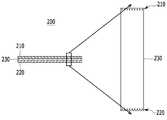
도 1은 본 발명의 제1 실시예에 따른 광학 필터(100)를 개략적으로 도시한 도면이다.1 is a view schematically showing an
도 1에 도시된 바와 같이, 본 발명의 제1 실시예에 따른 광학 필터(100)는 양 면에 미세 형상의 구조체(110, 120)가 형성되어 있는 필름 형태의 광학 필터이다. 여기서, 미세 형상 구조체(110, 120)는 모스 아이의 구조를 갖는다. 이러한 미세 형상 구조체(110, 120)는 다양한 형태를 가질 수 있으며, 예를 들어 도 1에서와 같이 외면이 오목한 원추 형상일 수 있다. 또한, 미세 형상 구조체(110, 120)의 개수 및 크기 등에 대해서는 미세 형상 구조체(110, 120)를 통해 투과되는 광의 특성에 따라 다양하게 설정될 수 있다.As shown in FIG. 1, the
광학 필터(100)에서 미세 형상의 구조체(110, 120)를 제외한 영역, 즉 광 흡수체(130)는 적외선 영역의 광을 흡수하는 물질이 분산된 자외선(UV:Ultra Violet) 광경화성 레진으로 이루어진다. 또한, 광 흡수체(130)에는 염료가 더 포함되며, 이러한 염료의 농도 조절에 따라 광 흡수체(130)의 두께 조절이 가능해진다.The region excluding the
여기서, 적외선 영역의 광을 흡수하는 물질은 광학 필터(100)를 통해 투과시키지 않을 적외선 영역의 파장 대역을 흡수할 수 있는 물질로써 구성되며, 이러한 물질에 대해서는 공지의 방법을 통해 구성할 수 있다.Here, the material that absorbs light in the infrared region is composed of a material capable of absorbing the wavelength band of the infrared region not to be transmitted through the
이와 같이, 본 발명의 제1 실시예에 따른 광학 필터(100)에서는 그 양면에 미세 형상의 구조체를 형성함으로써 프레넬 반사가 줄어들어 넓은 입사각 영역에서 보다 좋은 가시광선 영역의 투과 효율이 높아진다.As described above, in the
또한, 종래와 같이 광학 필터의 한 면에 반사 코팅을 구현하는 대신에 미세 형상의 구조체를 형성함으로써 원자재의 절감과 공정 시간, 소요 장비 및 작업 인력의 절감을 가져옴으로써 결과적으로 전체적인 제조 비용을 절감할 수가 있다.Also, instead of implementing a reflective coating on one side of an optical filter as in the prior art, by forming a fine structure, it is possible to reduce raw materials, reduce processing time, equipment and manpower, There is a number.
또한, 기판을 사용하지 않음으로 인해 역시 원자재의 절감을 가져올 수 있으며, 유리가 아닌 레진의 채용으로 기존의 유리 소재가 갖는 외부 충격에 약하다는 단점을 보완할 수 있다.In addition, since the substrate is not used, it is possible to reduce the raw material and it is possible to compensate the drawback that the glass material is weak against the external impact due to the adoption of the non-glass resin.
이러한 다수의 효과들로 인해 기존의 고가의 광학 필터에 비해 성능은 개선되고 단가는 상대적으로 저렴한 광학 필터를 제공할 수 있게 된다.Such a plurality of effects can provide an optical filter with improved performance and lower unit cost than conventional expensive optical filters.
다음, 본 발명의 제2 실시예에 따른 미세 형상 구조체를 갖는 광학 필터에 대해 설명한다.Next, an optical filter having a fine structure according to a second embodiment of the present invention will be described.
도 2는 본 발명의 제2 실시예에 따른 광학 필터(200)를 개략적으로 도시한 도면이다.2 is a view schematically showing an
도 2에 도시된 바와 같이, 본 발명의 제2 실시예에 따른 광학 필터(200)도 도 1에 도시된 제1 실시예에 따른 광학 필터(100)와 같이 양 면에 미세 형상의 구조체(210, 220)가 형성되어 있는 필름 형태의 광학 필터이다. 여기서, 미세 형상 구조체(210, 220)도 역시 모스 아이의 구조를 갖는다. 이러한 미세 형상 구조체(210, 220)는 외면이 볼록한 원추 형상을 갖는다.2, the
또한, 광학 필터(200)에서 미세 형상의 구조체(210, 220)를 제외한 영역, 즉 광 흡수체(230)는 적외선 영역의 광을 흡수하는 물질이 분산된 UV 광경화성 레진이다. 또한, 광 흡수체(230)에는 염료가 더 포함되며, 이러한 염료의 농도 조절에 따라 광 흡수체(230)의 두께 조절이 가능해진다.In the
본 발명의 제2 실시예에 따른 광학 필터(200)와 제1 실시예에 따른 광학 필터(100)는 양면에 형성된 미세 형상의 구조체(110, 120, 210, 220)의 형상에서만 차이가 있다.The
이하, 도면을 참조하여 본 발명의 제1 실시예에 따른 광학 필터(100)의 제조 방법에 대해 설명한다.Hereinafter, a method of manufacturing the
도 3은 도 1에 도시된 광학 필터(100)의 제조 방법의 흐름도이다.3 is a flow chart of a method of manufacturing the
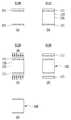
도 3의 (a)를 참조하면, 도 1에 도시된 바와 같은 광학 필터(100)의 미세 형상 구조체(110, 120)를 형성하기 위해 미세 형상 구조체(110)에 대응되는 미세 형상 구조체가 형성되어 있는 몰드 필름(111)과 미세 형상 구조체(120)에 대응되는 미세 형상 구조체가 형성되어 있는 몰드 필름(121)을 준비한다(S100). 여기서, 몰드 필름(111, 121)에 각각 미세 형상의 구조체는 이미 공지된 기술을 사용하여 제조될 수 있다.Referring to FIG. 3A, a fine structure corresponding to the
다음, 도 3의 (b)를 참조하면, 도 1에 도시된 광 흡수체(130)에 해당되는 금형(131)의 상부와 하부에 각각 몰드 필름(111, 121)을 배치하여 형폐한 후 형폐된 내부 공간(133)에 적외선 영역의 광을 흡수하는 물질이 분산된 UV 광경화성 레진을 주입한다(S110). 이와 달리, 금형(131)에 몰드 필름(111, 121)으로 형폐하기 전에 적외선 영역의 광을 흡수하는 물질이 분산된 UV 광경화성 레진을 주입한 후 몰드 필름(111, 121)을 형폐할 수도 있다.Next, referring to FIG. 3B, the
계속해서, 도 3의 (c)를 참조하면, 상기 단계(S110)에서 적외선 영역의 광을 흡수하는 물질이 분산된 UV 광경화성 레진이 주입된 몰드 필름(111, 121)의 외부에서 UV를 조사하여 레진을 UV 경화시킨다(S120).3 (c), in step S110, UV light is irradiated from the outside of the
그 후, 도 3의 (d) 및 (e)를 참조하면, 몰드 필름(111, 121)을 형개하면(S130) 외부 양면에 미세 형상의 구조체(110, 120)가 형성된 광학 필터(100)가 몰드 필름(111, 121)으로부터 이형되어 최종의 광학 필터(100)가 완성된다(S140).3 (d) and 3 (e), when the
본 발명의 제2 실시예에 해당되는 도 2에 도시된 광학 필터(200)에 대해서도 도 3에 도시된 제조 방법을 사용하여 제조될 수 있지만, 이 경우, 도 1에서와 다른 미세 형상 구조체(210, 220)를 형성하여야 하므로 몰드 필름(111, 121)에 형성된 미세 형상 구조체가 미세 형상 구조체(210, 220)에 대응되는 것만이 상이하므로, 이에 대해서는 도 3을 참조하는 경우 광학 필터(200)의 제조 방법이 쉽게 이해될 것이다.The
다음, 본 발명의 제3 실시예에 따른 미세 형상 구조체를 갖는 광학 필터에 대해 설명한다.Next, an optical filter having a fine structure according to a third embodiment of the present invention will be described.
도 4는 본 발명의 제3 실시예에 따른 광학 필터(300)를 개략적으로 도시한 도면이다.4 is a view schematically showing an
도 4에 도시된 바와 같이, 본 발명의 제3 실시예에 따른 광학 필터(300)는 도 1에 도시된 제1 실시예에 따른 광학 필터(100)와 같이 양 면에 미세 형상의 구조체(310, 320)가 형성되어 있는 필름 형태의 광학 필터이다. 여기서, 미세 형상 구조체(310, 320)도 역시 모스 아이의 구조를 갖는다. 이러한 미세 형상 구조체(310, 320)는 외면이 오목한 원추 형상을 갖는다.As shown in FIG. 4, the
또한, 광학 필터(300)에서 미세 형상의 구조체(310, 320)를 제외한 영역, 즉 광 흡수체(330)는 적외선 영역의 광을 흡수하는 물질과 나노 파우더가 분산된 UV 광경화성 레진이다. 또한, 광 흡수체(330)에는 염료가 더 포함되며, 이러한 염료의 농도 조절에 따라 광 흡수체(330)의 두께 조절이 가능해진다.The region excluding the
또한, 본 발명의 제3 실시예에 따른 광학 필터(300)는 광 흡수체(330)에 주입된 나노 파우더에 의해 광 흡수체(330)의 경도, 나아가 광학 필터(300)의 경도를 강화된다. 따라서, 광 흡수체(330)에 주입되는 나노 파우더의 양에 따라서 광학 필터(300)의 경도를 조절할 수가 있다. 이러한 경도는 6H 수준으로 높게 형성될 수 있다.The
본 발명의 제3 실시예에 따른 광학 필터(300)가 제1 실시예에 따른 광학 필터(100)와 다른 점은 광 흡수체(330)에 나노 파우더가 더 주입된다는 것에 있다.The
따라서, 본 발명의 제3 실시예에 따른 광학 필터(300)는 상기한 도 3에서의 제조 방법에 따라서 제조될 수 있으며, 이 때 도 3의 (b)에서 적외선 영역의 광을 흡수하는 물질 이외에 나노 파우더가 분산된 UV 광경화성 레진을 주입함으로써 그 과정이 대체될 수 있다.Therefore, the
다음, 본 발명의 제4 실시예에 따른 미세 형상 구조체를 갖는 광학 필터에 대해 설명한다.Next, an optical filter having a fine structure according to a fourth embodiment of the present invention will be described.
도 5는 본 발명의 제4 실시예에 따른 광학 필터(400)를 개략적으로 도시한 도면이다.5 is a view schematically showing an
도 5에 도시된 바와 같이, 본 발명의 제4 실시예에 따른 광학 필터(400)도 도 6에 도시된 제3 실시예에 따른 광학 필터(300)와 같이 양 면에 미세 형상의 구조체(410, 420)가 형성되어 있는 필름 형태의 광학 필터이다. 여기서, 미세 형상 구조체(410, 420)도 역시 모스 아이의 구조를 갖는다. 이러한 미세 형상 구조체(410, 420)는 외면이 볼록한 원추 형상을 갖는다.As shown in FIG. 5, the
또한, 광학 필터(400)에서 미세 형상의 구조체(410, 420)를 제외한 영역, 즉 광 흡수체(430)는 적외선 영역의 광을 흡수하는 물질과 나노 파우더가 분산된 UV 광경화성 레진이다. 또한, 광 흡수체(430)에는 염료가 더 포함되며, 이러한 염료의 농도 조절에 따라 광 흡수체(430)의 두께 조절이 가능해진다.The region excluding the
물론, 본 발명의 제3 실시예에서와 같이 제4 실시예에서도 광학 필터(400)는 광 흡수체(430)에 주입된 나노 파우더에 의해 광 흡수체(430)의 경도, 나아가 광학 필터(400)의 경도가 강화된다. 따라서, 광 흡수체(430)에 주입되는 나노 파우더의 양에 따라서 광학 필터(400)의 경도를 조절할 수가 있다. 이러한 경도는 6H 수준으로 높게 형성될 수 있다.As in the third embodiment of the present invention, as in the third embodiment of the present invention, in the fourth embodiment, the
본 발명의 제4 실시예에 따른 광학 필터(400)와 제3 실시예에 따른 광학 필터(300)는 양 면에 형성된 미세 형상의 구조체(310, 320, 410, 420)의 형상에서만 차이가 있다.The
따라서, 본 발명의 제4 실시예에 따른 광학 필터(400)도 상기한 도 3에서의 제조 방법에 따라서 제조될 수 있으며, 이 때 도 3의 (b)에서 적외선 영역의 광을 흡수하는 물질 이외에 나노 파우더가 분산된 UV 광경화성 레진을 주입함으로써 그 과정이 대체될 수 있다.Therefore, the
다음, 본 발명의 제5 실시예에 따른 미세 형상 구조체를 갖는 광학 필터에 대해 설명한다.Next, an optical filter having a fine structure according to a fifth embodiment of the present invention will be described.
도 6은 본 발명의 제5 실시예에 따른 광학 필터(500)를 개략적으로 도시한 도면이다.6 is a view schematically showing an
도 6에 도시된 바와 같이, 본 발명의 제5 실시예에 따른 광학 필터(500)는 광 흡수체(530)와 광 흡수체(530)의 양 면에 부착되어 있는 필름(510, 520)을 포함한다.6, the
필름(510, 520)은 광 흡수체(530)에 부착되지 않는 면에 각각 미세 형상 구조체가 형성되어 있으며, 이러한 미세 형상 구조체도 역시 모스 아이의 구조를 갖는다. 이러한 미세 형상 구조체는 외면이 오목한 원추 형상을 갖는다.Each of the
광 흡수체(530)는 적외선 영역의 광을 흡수하는 물질이 분산된 UV 광경화성 레진이거나 또는 적외선 영역의 광을 흡수하는 물질과 나노 파우더가 분산된 UV 광경화성 레진으로 구성된다.The
또한, 광 흡수체(530)에는 염료가 더 포함되며, 이러한 염료의 농도 조절에 따라 광 흡수체(530)의 두께 조절이 가능해진다.In addition, the
광 흡수체(530)에 나노 파우더가 포함되는 경우, 광 흡수체(530)에 포함된 나노 파우더에 의해 광 흡수체(530)의 경도, 나아가 광학 필터(500)의 경도가 강화될 수 있다. 따라서, 광 흡수체(530)에 포함되는 나노 파우더의 양에 따라서 광학 필터(500)의 경도를 조절할 수가 있다. 이러한 경도는 6H 수준으로 높게 형성될 수 있다.When the nano powder is included in the
본 발명의 제5 실시예에 따른 광학 필터(500)는 상기한 도 3에서의 제조 방법에 따라서 제조될 수 있으며, 이 때 미세 형상 구조체가 형성되어 있는 몰드 필름(111, 121) 대신에 미세 형상 구조체가 형성되어 있는 필름(510, 520)이 대신 사용됨으로써 그 과정이 대체될 수 있다. 이 때, 미세 형상 구조체가 형성되어 있는 필름(510, 520)도 공지된 기술을 사용하여 제조될 수 있다.The
다음, 본 발명의 제6 실시예에 따른 미세 형상 구조체를 갖는 광학 필터에 대해 설명한다.Next, an optical filter having a fine structure according to a sixth embodiment of the present invention will be described.
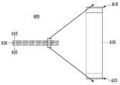
도 7은 본 발명의 제6 실시예에 따른 광학 필터(600)를 개략적으로 도시한 도면이다.7 is a view schematically showing an
도 7에 도시된 바와 같이, 본 발명의 제6 실시예에 따른 광학 필터(600)는 미세 형상 구조체의 형상을 제외하고는 제 5 실시예에 따른 광학 필터(500)와 그 구조가 동일하다. 즉, 본 발명의 제6 실시예에 따른 광학 필터(600)도 광 흡수체(630)와 광 흡수체(630)의 양 면에 부착되어 있는 필름(610, 620)을 포함한다.As shown in FIG. 7, the
이러한 광 흡수체(630)는 제5 실시예에 따른 광학 필터(500)에서의 광 흡수체(530)와 동일하다.Such a
다만, 필름(610, 620)에서 광 흡수체(630)에 부착되지 않는 면에 각각 미세 형상 구조체가 형성되어 있는데, 이러한 미세 형상 구조체도 역시 모스 아이의 구조를 갖지만, 다만, 이러한 미세 형상 구조체의 형상이 외면이 볼록한 원추 형상을 갖는다는 점이 상이하다.However, the microstructures are formed on the surfaces of the
다음, 본 발명의 제7 실시예에 따른 미세 형상 구조체를 갖는 광학 필터에 대해 설명한다.Next, an optical filter having a fine structure according to a seventh embodiment of the present invention will be described.
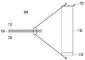
도 8은 본 발명의 제7 실시예에 따른 광학 필터(700)를 개략적으로 도시한 도면이다.8 is a view schematically showing an
도 8에 도시된 바와 같이, 본 발명의 제7 실시예에 따른 광학 필터(700)는 광 흡수체(730)를 포함하고, 광 흡수체(730)의 한 면에는 적외선 차단 필터(710)가 형성되어 있고, 다른 면에는 미세 형상의 구조체(720)가 형성되어 있는 필름 형태의 광학 필터이다. 여기서, 미세 형상 구조체(720)도 역시 모스 아이의 구조를 갖는다. 이러한 미세 형상 구조체(720)는 도 8에 도시된 바와 같이, 도 1에 도시된 미세 형상 구조체(110)와 같이 외면이 오목한 원추 형상이거나 또는 도 8에 도시하지는 않았지만 도 2에 도시된 미세 형상 구조체(210)와 같이 외면이 볼록한 원추 형상일 수 있다.8, the
광 흡수체(730)는 적외선 영역의 광을 흡수하는 물질 또는 적외선 영역의 광을 흡수하는 물질과 나노 파우더가 분산된 UV 광경화성 레진이다. 또한, 광 흡수체(730)에는 염료가 더 포함되며, 이러한 염료의 농도 조절에 따라 광 흡수체(730)의 두께 조절이 가능해진다. 또한, 나노 파우더의 양에 따라서 광학 필터(700)의 경도를 조절할 수가 있다.The
적외선 차단 필터(710)는 적외선 차단층이 형성된 유리 기판이거나 또는 광 흡수체(730)에 대한 증착에 의해 형성되는 적외선 차단 코팅막이다.The infrared cut-
본 발명의 제7 실시예에 따른 광학 필터(700)도 상기한 도 3에서의 제조 방법을 사용하여 제조될 수 있다. 물론, 적외선 차단 필터(710)를 형성하는 방법에 따라 상기한 도 3에서의 제조 방법이 변형되어야 하지만, 이러한 변형도 본 기술분야의 당업자에 의해 쉽게 적용될 수 있을 것이다.The
다음, 본 발명의 제8 실시예에 따른 미세 형상 구조체를 갖는 광학 필터에 대해 설명한다.Next, an optical filter having a fine structure according to an eighth embodiment of the present invention will be described.
도 9는 본 발명의 제8 실시예에 따른 광학 필터(800)를 개략적으로 도시한 도면이다.9 is a view schematically showing an
도 9에 도시된 바와 같이, 본 발명의 제8 실시예에 따른 광학 필터(800)는 광 흡수체(830)를 포함하고, 광 흡수체(830)의 한 면에는 적외선 차단 필터(810)가 형성되어 있고, 다른 면에는 미세 형상의 구조체가 형성되어 있는 필름(820)을 포함한다.9, the
적외선 차단 필터(810)는 적외선 차단층이 형성된 유리 기판이거나 또는 광 흡수체(830)에 대한 증착에 의해 형성되는 적외선 차단 코팅막이다.The infrared cut-
필름(820)은 광 흡수체(830)에 부착되지 않는 면에 미세 형상 구조체가 형성되어 있으며, 이러한 미세 형상 구조체도 역시 모스 아이의 구조를 갖는다. 이러한 미세 형상 구조체는 도 1에 도시된 미세 형상 구조체(110)와 같이 외면이 오목한 원추 형상이거나 또는 도 2에 도시된 미세 형상 구조체(210)와 같이 외면이 볼록한 원추 형상이다.The
광 흡수체(830)는 적외선 영역의 광을 흡수하는 물질 또는 적외선 영역의 광을 흡수하는 물질과 나노 파우더가 분산된 UV 광경화성 레진이다. 또한, 광 흡수체(830)에는 염료가 더 포함되며, 이러한 염료의 농도 조절에 따라 광 흡수체(830)의 두께 조절이 가능해진다. 또한, 나노 파우더의 양에 따라서 광학 필터(800)의 경도를 조절할 수가 있다.The
본 발명의 제8 실시예에 따른 광학 필터(800)도 상기한 도 3에서의 제조 방법을 사용하여 제조될 수 있다. 물론, 적외선 차단 필터(810)를 형성하는 방법에 따라 상기한 도 3에서의 제조 방법이 변형되어야 하지만, 이러한 변형도 본 기술분야의 당업자에 의해 쉽게 적용될 수 있을 것이다.The
이상에서 본 발명의 실시예에 대하여 상세하게 설명하였지만 본 발명의 권리범위는 이에 한정되는 것은 아니고 다음의 청구범위에서 정의하고 있는 본 발명의 기본 개념을 이용한 당업자의 여러 변형 및 개량 형태 또한 본 발명의 권리범위에 속하는 것이다.While the present invention has been particularly shown and described with reference to exemplary embodiments thereof, it is to be understood that the invention is not limited to the disclosed exemplary embodiments, It belongs to the scope of right.
Claims (1)
Translated fromKorean외부 광이 입사되어 상기 광학 필터를 투과하는 과정에서 상기 광 흡수체가 상기 외부 광으로부터 적외선 영역의 광을 흡수하여 상기 광학 필터가 블루 필터로 동작하도록 하는,
필름 형태의 광학 필터.A light absorber composed of a photo-curing resin in which a substance absorbing light in the infrared region is dispersed from light incident from the outside and formed of a fine structure on both sides,
Wherein the optical absorber absorbs the light in the infrared region from the external light so that the optical filter operates as a blue filter when external light is incident and is transmitted through the optical filter,
Optical filters in film form.
Priority Applications (1)
| Application Number | Priority Date | Filing Date | Title |
|---|---|---|---|
| KR1020170046948AKR20170042276A (en) | 2017-04-11 | 2017-04-11 | Optic filter having sub-micron structure and method for manufacturing the same |
Applications Claiming Priority (1)
| Application Number | Priority Date | Filing Date | Title |
|---|---|---|---|
| KR1020170046948AKR20170042276A (en) | 2017-04-11 | 2017-04-11 | Optic filter having sub-micron structure and method for manufacturing the same |
Related Parent Applications (1)
| Application Number | Title | Priority Date | Filing Date |
|---|---|---|---|
| KR1020150096806ADivisionKR20170010118A (en) | 2015-07-07 | 2015-07-07 | Optic filter having sub-micron structure and method for manufacturing the same |
Publications (1)
| Publication Number | Publication Date |
|---|---|
| KR20170042276Atrue KR20170042276A (en) | 2017-04-18 |
Family
ID=58704124
Family Applications (1)
| Application Number | Title | Priority Date | Filing Date |
|---|---|---|---|
| KR1020170046948AWithdrawnKR20170042276A (en) | 2017-04-11 | 2017-04-11 | Optic filter having sub-micron structure and method for manufacturing the same |
Country Status (1)
| Country | Link |
|---|---|
| KR (1) | KR20170042276A (en) |
Cited By (2)
| Publication number | Priority date | Publication date | Assignee | Title |
|---|---|---|---|---|
| KR102077933B1 (en)* | 2018-08-09 | 2020-02-14 | 강성국 | Method of forming color or patterns on films using ultraviolet and forming apparatus operated by the same |
| KR20210074767A (en)* | 2019-12-12 | 2021-06-22 | 주식회사 이엘피 | Uv-ir absorption filter with aspherical shape and manufacturing method thereof |
- 2017
- 2017-04-11KRKR1020170046948Apatent/KR20170042276A/ennot_activeWithdrawn
Cited By (2)
| Publication number | Priority date | Publication date | Assignee | Title |
|---|---|---|---|---|
| KR102077933B1 (en)* | 2018-08-09 | 2020-02-14 | 강성국 | Method of forming color or patterns on films using ultraviolet and forming apparatus operated by the same |
| KR20210074767A (en)* | 2019-12-12 | 2021-06-22 | 주식회사 이엘피 | Uv-ir absorption filter with aspherical shape and manufacturing method thereof |
Similar Documents
| Publication | Publication Date | Title |
|---|---|---|
| US6886937B2 (en) | Ophthalmic lens with graded interference coating | |
| CN101135743B (en) | Optical filter and camera | |
| US8270080B2 (en) | Diffractive optical element and method for manufacturing same | |
| US8292430B2 (en) | Tinted semi-finished lens having impact resistance and method for manufacturing the same | |
| US20230146460A1 (en) | Method for forming an optical article comprising microlenses | |
| CN202815253U (en) | Diffractive optical element | |
| CN101354447A (en) | Optical element | |
| JP2022183217A (en) | Method for molding polarizing film and method for manufacturing polarizing lens | |
| US8665520B2 (en) | Neutral density optical filter and image pickup apparatus | |
| KR20170042276A (en) | Optic filter having sub-micron structure and method for manufacturing the same | |
| US20080273239A1 (en) | Imaging lens and method of manufacturing the same | |
| KR20170010118A (en) | Optic filter having sub-micron structure and method for manufacturing the same | |
| CN221860789U (en) | A high refractive index blue light blocking polarized resin lens | |
| KR101746076B1 (en) | Lens having sub-micron structure and method for manufacturing the same | |
| JP2016071278A (en) | Optical filter and light quantity adjusting device, and imaging apparatus | |
| KR20160123671A (en) | Multi-layered lens and method for manufacturing the same | |
| CN117940275A (en) | Method for producing an optical structure and optical structure | |
| JP2008139748A (en) | Composite optical element, composite optical element manufacturing method, and composite optical element manufacturing apparatus | |
| JP2019207326A (en) | Diffraction optical element, and optical instrument using the same | |
| CN211718644U (en) | High-refractive-index color-changing lens | |
| KR20210032855A (en) | Blue light protecting and low-reflection optical member and the manufacturing method thereof | |
| US20240036234A1 (en) | Lens and lens device | |
| KR20190122062A (en) | Manufacturing Method of Polarizing Lens having Photochromic and Ultraviolet Protection Functions | |
| KR100706959B1 (en) | Lens assembly with infrared absorption glass | |
| KR20170006216A (en) | Method for manufacturing non-reflecting sub-micron structure |
Legal Events
| Date | Code | Title | Description |
|---|---|---|---|
| A107 | Divisional application of patent | ||
| PA0107 | Divisional application | Comment text:Divisional Application of Patent Patent event date:20170411 Patent event code:PA01071R01D Filing date:20150707 Application number text:1020150096806 | |
| PG1501 | Laying open of application | ||
| PC1203 | Withdrawal of no request for examination |