KR20170038727A - Polarizing plate inspection method and inspection apparatus - Google Patents
Polarizing plate inspection method and inspection apparatusDownload PDFInfo
- Publication number
- KR20170038727A KR20170038727AKR1020160125736AKR20160125736AKR20170038727AKR 20170038727 AKR20170038727 AKR 20170038727AKR 1020160125736 AKR1020160125736 AKR 1020160125736AKR 20160125736 AKR20160125736 AKR 20160125736AKR 20170038727 AKR20170038727 AKR 20170038727A
- Authority
- KR
- South Korea
- Prior art keywords
- defect candidate
- polarizing plate
- defect
- light
- section
- Prior art date
- Legal status (The legal status is an assumption and is not a legal conclusion. Google has not performed a legal analysis and makes no representation as to the accuracy of the status listed.)
- Granted
Links
- 238000000034methodMethods0.000titleclaimsabstractdescription55
- 238000007689inspectionMethods0.000titleclaimsdescription27
- 230000007547defectEffects0.000claimsabstractdescription160
- 238000004519manufacturing processMethods0.000claimsdescription16
- 238000003384imaging methodMethods0.000claimsdescription14
- 238000000605extractionMethods0.000claimsdescription5
- 238000011144upstream manufacturingMethods0.000claimsdescription3
- 230000001681protective effectEffects0.000description31
- 239000003637basic solutionSubstances0.000description28
- 229920005989resinPolymers0.000description24
- 239000011347resinSubstances0.000description24
- 239000010410layerSubstances0.000description17
- 239000000126substanceSubstances0.000description16
- 229910052783alkali metalInorganic materials0.000description13
- -1polypropylenePolymers0.000description13
- 239000003929acidic solutionSubstances0.000description12
- 150000001340alkali metalsChemical class0.000description11
- 229910052784alkaline earth metalInorganic materials0.000description11
- 150000001342alkaline earth metalsChemical class0.000description10
- 239000000463materialSubstances0.000description10
- 239000004820Pressure-sensitive adhesiveSubstances0.000description9
- 238000011282treatmentMethods0.000description9
- 238000010521absorption reactionMethods0.000description8
- 238000002834transmittanceMethods0.000description8
- XLYOFNOQVPJJNP-UHFFFAOYSA-NwaterSubstancesOXLYOFNOQVPJJNP-UHFFFAOYSA-N0.000description8
- 230000002950deficientEffects0.000description7
- WMFOQBRAJBCJND-UHFFFAOYSA-MLithium hydroxideChemical compound[Li+].[OH-]WMFOQBRAJBCJND-UHFFFAOYSA-M0.000description6
- KWYUFKZDYYNOTN-UHFFFAOYSA-MPotassium hydroxideChemical compound[OH-].[K+]KWYUFKZDYYNOTN-UHFFFAOYSA-M0.000description6
- HEMHJVSKTPXQMS-UHFFFAOYSA-MSodium hydroxideChemical compound[OH-].[Na+]HEMHJVSKTPXQMS-UHFFFAOYSA-M0.000description6
- 238000005520cutting processMethods0.000description6
- 238000001514detection methodMethods0.000description6
- 230000003287optical effectEffects0.000description6
- ZCYVEMRRCGMTRW-UHFFFAOYSA-N7553-56-2Chemical compound[I]ZCYVEMRRCGMTRW-UHFFFAOYSA-N0.000description5
- LFQSCWFLJHTTHZ-UHFFFAOYSA-NEthanolChemical compoundCCOLFQSCWFLJHTTHZ-UHFFFAOYSA-N0.000description5
- 239000004372Polyvinyl alcoholSubstances0.000description5
- 150000007513acidsChemical class0.000description5
- 238000001035dryingMethods0.000description5
- 238000005286illuminationMethods0.000description5
- 229910052740iodineInorganic materials0.000description5
- 239000011630iodineSubstances0.000description5
- 229920002451polyvinyl alcoholPolymers0.000description5
- 239000002335surface treatment layerSubstances0.000description5
- VEXZGXHMUGYJMC-UHFFFAOYSA-NHydrochloric acidChemical compoundClVEXZGXHMUGYJMC-UHFFFAOYSA-N0.000description4
- QAOWNCQODCNURD-UHFFFAOYSA-NSulfuric acidChemical compoundOS(O)(=O)=OQAOWNCQODCNURD-UHFFFAOYSA-N0.000description4
- 150000007514basesChemical class0.000description4
- 238000004140cleaningMethods0.000description4
- 239000000470constituentSubstances0.000description4
- 230000032798delaminationEffects0.000description4
- 238000004080punchingMethods0.000description4
- 238000012360testing methodMethods0.000description4
- QTBSBXVTEAMEQO-UHFFFAOYSA-NAcetic acidChemical compoundCC(O)=OQTBSBXVTEAMEQO-UHFFFAOYSA-N0.000description3
- OKKJLVBELUTLKV-UHFFFAOYSA-NMethanolChemical compoundOCOKKJLVBELUTLKV-UHFFFAOYSA-N0.000description3
- MUBZPKHOEPUJKR-UHFFFAOYSA-NOxalic acidChemical compoundOC(=O)C(O)=OMUBZPKHOEPUJKR-UHFFFAOYSA-N0.000description3
- 239000000853adhesiveSubstances0.000description3
- 230000001070adhesive effectEffects0.000description3
- 239000012790adhesive layerSubstances0.000description3
- 230000015572biosynthetic processEffects0.000description3
- KRKNYBCHXYNGOX-UHFFFAOYSA-Ncitric acidChemical compoundOC(=O)CC(O)(C(O)=O)CC(O)=OKRKNYBCHXYNGOX-UHFFFAOYSA-N0.000description3
- 150000002148estersChemical class0.000description3
- 150000004679hydroxidesChemical class0.000description3
- 239000007788liquidSubstances0.000description3
- 229920000219Ethylene vinyl alcoholPolymers0.000description2
- GRYLNZFGIOXLOG-UHFFFAOYSA-NNitric acidChemical compoundO[N+]([O-])=OGRYLNZFGIOXLOG-UHFFFAOYSA-N0.000description2
- 239000004698PolyethyleneSubstances0.000description2
- 239000004743PolypropyleneSubstances0.000description2
- CDBYLPFSWZWCQE-UHFFFAOYSA-LSodium CarbonateChemical compound[Na+].[Na+].[O-]C([O-])=OCDBYLPFSWZWCQE-UHFFFAOYSA-L0.000description2
- 238000002441X-ray diffractionMethods0.000description2
- 230000002411adverseEffects0.000description2
- WPYMKLBDIGXBTP-UHFFFAOYSA-Nbenzoic acidChemical compoundOC(=O)C1=CC=CC=C1WPYMKLBDIGXBTP-UHFFFAOYSA-N0.000description2
- 238000005422blastingMethods0.000description2
- 238000011088calibration curveMethods0.000description2
- 230000001413cellular effectEffects0.000description2
- 229920006026co-polymeric resinPolymers0.000description2
- 150000001925cycloalkenesChemical class0.000description2
- 238000004090dissolutionMethods0.000description2
- 239000012467final productSubstances0.000description2
- 238000010191image analysisMethods0.000description2
- 238000010030laminatingMethods0.000description2
- 238000000608laser ablationMethods0.000description2
- BDAGIHXWWSANSR-UHFFFAOYSA-Nmethanoic acidNatural productsOC=OBDAGIHXWWSANSR-UHFFFAOYSA-N0.000description2
- 150000007522mineralic acidsChemical class0.000description2
- 229910017604nitric acidInorganic materials0.000description2
- 230000010287polarizationEffects0.000description2
- 229920006122polyamide resinPolymers0.000description2
- 229920005668polycarbonate resinPolymers0.000description2
- 239000004431polycarbonate resinSubstances0.000description2
- 229920000573polyethylenePolymers0.000description2
- 229920000139polyethylene terephthalatePolymers0.000description2
- 239000005020polyethylene terephthalateSubstances0.000description2
- 229920001155polypropylenePolymers0.000description2
- 238000012545processingMethods0.000description2
- 239000002904solventSubstances0.000description2
- 239000000758substrateSubstances0.000description2
- 238000011179visual inspectionMethods0.000description2
- OSWFIVFLDKOXQC-UHFFFAOYSA-N4-(3-methoxyphenyl)anilineChemical compoundCOC1=CC=CC(C=2C=CC(N)=CC=2)=C1OSWFIVFLDKOXQC-UHFFFAOYSA-N0.000description1
- 239000004925Acrylic resinSubstances0.000description1
- 229920000178Acrylic resinPolymers0.000description1
- 239000005711Benzoic acidSubstances0.000description1
- 229920002284Cellulose triacetatePolymers0.000description1
- KRHYYFGTRYWZRS-UHFFFAOYSA-NFluoraneChemical compoundFKRHYYFGTRYWZRS-UHFFFAOYSA-N0.000description1
- VMHLLURERBWHNL-UHFFFAOYSA-MSodium acetateChemical compound[Na+].CC([O-])=OVMHLLURERBWHNL-UHFFFAOYSA-M0.000description1
- 206010042674SwellingDiseases0.000description1
- NNLVGZFZQQXQNW-ADJNRHBOSA-N[(2r,3r,4s,5r,6s)-4,5-diacetyloxy-3-[(2s,3r,4s,5r,6r)-3,4,5-triacetyloxy-6-(acetyloxymethyl)oxan-2-yl]oxy-6-[(2r,3r,4s,5r,6s)-4,5,6-triacetyloxy-2-(acetyloxymethyl)oxan-3-yl]oxyoxan-2-yl]methyl acetateChemical compoundO([C@@H]1O[C@@H]([C@H]([C@H](OC(C)=O)[C@H]1OC(C)=O)O[C@H]1[C@@H]([C@@H](OC(C)=O)[C@H](OC(C)=O)[C@@H](COC(C)=O)O1)OC(C)=O)COC(=O)C)[C@@H]1[C@@H](COC(C)=O)O[C@@H](OC(C)=O)[C@H](OC(C)=O)[C@H]1OC(C)=ONNLVGZFZQQXQNW-ADJNRHBOSA-N0.000description1
- 235000011054acetic acidNutrition0.000description1
- NIXOWILDQLNWCW-UHFFFAOYSA-Nacrylic acid groupChemical groupC(C=C)(=O)ONIXOWILDQLNWCW-UHFFFAOYSA-N0.000description1
- 150000001298alcoholsChemical class0.000description1
- 235000010233benzoic acidNutrition0.000description1
- 238000000861blow dryingMethods0.000description1
- AXCZMVOFGPJBDE-UHFFFAOYSA-Lcalcium dihydroxideChemical compound[OH-].[OH-].[Ca+2]AXCZMVOFGPJBDE-UHFFFAOYSA-L0.000description1
- 239000000920calcium hydroxideSubstances0.000description1
- 229910001861calcium hydroxideInorganic materials0.000description1
- 239000012461cellulose resinSubstances0.000description1
- 235000015165citric acidNutrition0.000description1
- 239000011248coating agentSubstances0.000description1
- 238000000576coating methodMethods0.000description1
- 150000001875compoundsChemical class0.000description1
- 238000012937correctionMethods0.000description1
- 238000004132cross linkingMethods0.000description1
- 238000013016dampingMethods0.000description1
- 238000013461designMethods0.000description1
- 229920005994diacetyl cellulosePolymers0.000description1
- 229910003460diamondInorganic materials0.000description1
- 239000010432diamondSubstances0.000description1
- 239000000975dyeSubstances0.000description1
- 238000004043dyeingMethods0.000description1
- 230000000694effectsEffects0.000description1
- 238000005516engineering processMethods0.000description1
- 239000005038ethylene vinyl acetateSubstances0.000description1
- 235000019253formic acidNutrition0.000description1
- 229910052736halogenInorganic materials0.000description1
- 150000002367halogensChemical class0.000description1
- 229910000040hydrogen fluorideInorganic materials0.000description1
- XLYOFNOQVPJJNP-UHFFFAOYSA-MhydroxideChemical compound[OH-]XLYOFNOQVPJJNP-UHFFFAOYSA-M0.000description1
- 230000010365information processingEffects0.000description1
- 238000003475laminationMethods0.000description1
- 238000010330laser markingMethods0.000description1
- 239000004973liquid crystal related substanceSubstances0.000description1
- 239000003550markerSubstances0.000description1
- 238000005259measurementMethods0.000description1
- 229910052751metalInorganic materials0.000description1
- 239000002184metalSubstances0.000description1
- 229910001507metal halideInorganic materials0.000description1
- 150000005309metal halidesChemical class0.000description1
- 239000012046mixed solventSubstances0.000description1
- JFNLZVQOOSMTJK-KNVOCYPGSA-NnorborneneChemical compoundC1[C@@H]2CC[C@H]1C=C2JFNLZVQOOSMTJK-KNVOCYPGSA-N0.000description1
- 150000007524organic acidsChemical class0.000description1
- 235000005985organic acidsNutrition0.000description1
- 235000006408oxalic acidNutrition0.000description1
- 230000035699permeabilityEffects0.000description1
- 229920002120photoresistant polymerPolymers0.000description1
- 229920001200poly(ethylene-vinyl acetate)Polymers0.000description1
- 229920013716polyethylene resinPolymers0.000description1
- 229920005672polyolefin resinPolymers0.000description1
- 239000011118polyvinyl acetateSubstances0.000description1
- 229920002689polyvinyl acetatePolymers0.000description1
- 150000003839saltsChemical class0.000description1
- 238000012216screeningMethods0.000description1
- 239000001632sodium acetateSubstances0.000description1
- 235000017281sodium acetateNutrition0.000description1
- 229910000029sodium carbonateInorganic materials0.000description1
- 238000004611spectroscopical analysisMethods0.000description1
- 238000005507sprayingMethods0.000description1
- 238000004381surface treatmentMethods0.000description1
- 230000008961swellingEffects0.000description1
- KKEYFWRCBNTPAC-UHFFFAOYSA-Lterephthalate(2-)Chemical compound[O-]C(=O)C1=CC=C(C([O-])=O)C=C1KKEYFWRCBNTPAC-UHFFFAOYSA-L0.000description1
- 238000001291vacuum dryingMethods0.000description1
- 238000005406washingMethods0.000description1
Images


Classifications
- G—PHYSICS
- G01—MEASURING; TESTING
- G01N—INVESTIGATING OR ANALYSING MATERIALS BY DETERMINING THEIR CHEMICAL OR PHYSICAL PROPERTIES
- G01N21/00—Investigating or analysing materials by the use of optical means, i.e. using sub-millimetre waves, infrared, visible or ultraviolet light
- G01N21/84—Systems specially adapted for particular applications
- G01N21/88—Investigating the presence of flaws or contamination
- G01N21/8803—Visual inspection
- G—PHYSICS
- G01—MEASURING; TESTING
- G01N—INVESTIGATING OR ANALYSING MATERIALS BY DETERMINING THEIR CHEMICAL OR PHYSICAL PROPERTIES
- G01N21/00—Investigating or analysing materials by the use of optical means, i.e. using sub-millimetre waves, infrared, visible or ultraviolet light
- G01N21/84—Systems specially adapted for particular applications
- G01N21/88—Investigating the presence of flaws or contamination
- G01N21/95—Investigating the presence of flaws or contamination characterised by the material or shape of the object to be examined
- G01N21/958—Inspecting transparent materials or objects, e.g. windscreens
- G—PHYSICS
- G02—OPTICS
- G02B—OPTICAL ELEMENTS, SYSTEMS OR APPARATUS
- G02B1/00—Optical elements characterised by the material of which they are made; Optical coatings for optical elements
- G02B1/10—Optical coatings produced by application to, or surface treatment of, optical elements
- G02B1/14—Protective coatings, e.g. hard coatings
- G—PHYSICS
- G02—OPTICS
- G02B—OPTICAL ELEMENTS, SYSTEMS OR APPARATUS
- G02B5/00—Optical elements other than lenses
- G02B5/30—Polarising elements
- G02B5/3025—Polarisers, i.e. arrangements capable of producing a definite output polarisation state from an unpolarised input state
- G02B5/3033—Polarisers, i.e. arrangements capable of producing a definite output polarisation state from an unpolarised input state in the form of a thin sheet or foil, e.g. Polaroid
- G—PHYSICS
- G01—MEASURING; TESTING
- G01N—INVESTIGATING OR ANALYSING MATERIALS BY DETERMINING THEIR CHEMICAL OR PHYSICAL PROPERTIES
- G01N21/00—Investigating or analysing materials by the use of optical means, i.e. using sub-millimetre waves, infrared, visible or ultraviolet light
- G01N21/84—Systems specially adapted for particular applications
- G01N21/88—Investigating the presence of flaws or contamination
- G01N21/8851—Scan or image signal processing specially adapted therefor, e.g. for scan signal adjustment, for detecting different kinds of defects, for compensating for structures, markings, edges
- G01N2021/8854—Grading and classifying of flaws
- G01N2021/8874—Taking dimensions of defect into account
- G—PHYSICS
- G01—MEASURING; TESTING
- G01N—INVESTIGATING OR ANALYSING MATERIALS BY DETERMINING THEIR CHEMICAL OR PHYSICAL PROPERTIES
- G01N21/00—Investigating or analysing materials by the use of optical means, i.e. using sub-millimetre waves, infrared, visible or ultraviolet light
- G01N21/84—Systems specially adapted for particular applications
- G01N21/88—Investigating the presence of flaws or contamination
- G01N21/95—Investigating the presence of flaws or contamination characterised by the material or shape of the object to be examined
- G01N2021/9511—Optical elements other than lenses, e.g. mirrors
Landscapes
- Physics & Mathematics (AREA)
- General Physics & Mathematics (AREA)
- Analytical Chemistry (AREA)
- Health & Medical Sciences (AREA)
- Life Sciences & Earth Sciences (AREA)
- Chemical & Material Sciences (AREA)
- Optics & Photonics (AREA)
- Biochemistry (AREA)
- General Health & Medical Sciences (AREA)
- Immunology (AREA)
- Pathology (AREA)
- Polarising Elements (AREA)
- Investigating Materials By The Use Of Optical Means Adapted For Particular Applications (AREA)
- Liquid Crystal (AREA)
Abstract
Translated fromKoreanDescription
Translated fromKorean본 발명은 비편광부를 갖는 편광판의 검사 방법 및 검사 장치에 관한 것이다. 대표적으로는, 비편광부를 갖는 편광자를 포함하는 편광판의 검사 방법 및 검사 장치에 관한 것이다.The present invention relates to a method and an apparatus for inspecting a polarizing plate having a non-light-emitting portion. Typically, the present invention relates to a method and an apparatus for inspecting a polarizing plate including a polarizer having a non-light-emitting portion.
휴대 전화, 노트형 퍼스널 컴퓨터 (PC) 등의 화상 표시 장치에는, 카메라 등의 내부 전자 부품이 탑재되어 있는 것이 있다. 이와 같은 화상 표시 장치의 카메라 성능 등의 향상을 목적으로 하여, 여러 가지 검토가 이루어지고 있다 (예를 들어, 특허문헌 1 ∼ 7). 그러나, 스마트 폰, 터치 패널식의 정보 처리 장치의 급속한 보급에 의해서, 카메라 성능 등이 더욱 향상될 것이 요망되고 있다. 또, 화상 표시 장치의 형상의 다양화 및 고기능화에 대응하기 위해서, 부분적으로 편광 성능을 갖는 편광판이 요망되고 있다. 이들 요망을 공업적 및 상업적으로 실현하기 위해서는 허용 가능한 비용으로 화상 표시 장치 및/또는 그 부품을 제조하는 것이 요망되는 바, 그러한 기술을 확립하기 위해서는 여러 가지 검토 사항이 남아 있다.BACKGROUND ART [0002] An image display device such as a cellular phone or a notebook type personal computer (PC) has an internal electronic component such as a camera mounted thereon. For the purpose of improving the camera performance and the like of such an image display apparatus, various studies have been made (for example, Patent Documents 1 to 7). However, it is desired that the camera performance and the like are further improved by the rapid spread of smart phones and touch panel type information processing apparatuses. In addition, in order to cope with diversification and high functionality of the image display apparatus, a polarizing plate having a partial polarization performance is desired. In order to industrially and commercially realize these demands, it is desired to manufacture image display devices and / or parts thereof at an allowable expense, and various considerations remain in order to establish such a technology.
본 발명자들이, 부분적으로 편광 성능을 갖는 편광판으로서, 비편광부를 갖는 편광자를 사용하여 편광판을 제조하고, 얻어진 편광판을 외관 검사에 제공한 바, 비편광부가 결함으로서 잘못 검출된다는 문제에 직면하였다. 본 발명은, 당해 문제를 해결하기 위해서 이루어진 것으로서, 그 주된 목적은, 비편광부를 갖는 편광자를 포함하여, 장척 방향으로 소정 간격으로 배치된 비편광부를 갖는 장척상의 편광판의 외관을 바람직하게 검사하는 방법을 제공하는 것에 있다.The inventors of the present invention have faced with the problem that a polarizing plate having a partially polarizing function is produced by using a polarizer having a non-light-emitting portion and the resultant polarizing plate is provided for visual inspection, whereby the non-polarizing portion is erroneously detected as a defect. SUMMARY OF THE INVENTION The present invention has been made in order to solve the problem, and its main object is to provide a method for desirably inspecting the appearance of a long polarizing plate having a non-light-deflecting portion including a polarizer having a non-light- And the like.
본 발명에 의하면, 장척 방향으로 소정 간격으로 배치된 비편광부를 갖는 장척상의 편광판을, 그 장척 방향으로 반송하면서 그 외관을 검사하는 방법이 제공된다. 그 검사 방법은, 그 편광판을 촬상하여 화상 데이터를 취득하는 공정과, 그 화상 데이터를 해석하여 결함 후보부를 추출하는 공정과, 그 결함 후보부가 기준치 이하의 사이즈를 갖는지의 여부를 판단하는 공정과, 그 결함 후보부의 사이즈에 기초하여 결함을 검출하는 공정을 포함한다.According to the present invention, there is provided a method of inspecting the appearance of a polarizing plate having a non-light-emitting portion arranged at a predetermined interval in a long direction, while conveying the polarizing plate in its long direction. The inspection method includes a step of capturing image data of the polarizing plate to acquire image data, a step of analyzing the image data to extract a defect candidate portion, a step of judging whether or not the defect candidate portion has a size smaller than a reference value, And a step of detecting a defect based on the size of the defect candidate portion.
일 실시형태에 있어서는, 상기 편광판이, 장척 방향 및 폭 방향으로 소정 간격으로 배치된 비편광부를 갖는다.In one embodiment, the polarizing plate has a non-light-emitting portion disposed at predetermined intervals in the longitudinal direction and the width direction.
일 실시형태에 있어서는, 상기 화상 데이터의 취득이, 상기 편광판의 연속적인 촬상에 기초하여 행해진다.In one embodiment, the acquisition of the image data is performed based on continuous imaging of the polarizing plate.
일 실시형태에 있어서는, 상기 결함 후보부의 추출이, 상기 화상 데이터의 휘도 정보에 기초하여 행해진다.In one embodiment, the extraction of the defect candidate portion is performed based on the luminance information of the image data.
일 실시형태에 있어서는, 상기 결함 후보부가 상기 장척 방향으로 주기성을 갖는지의 여부를 판단하는 공정을 추가로 포함하고, 상기 결함을 검출하는 공정이, 상기 결함 후보부의 사이즈 및 주기성의 유무에 기초하여 결함을 검출하는 공정이다.In one embodiment, the method further includes a step of determining whether the defect candidate section has a periodicity in the longitudinal direction, and the step of detecting the defect includes a step of detecting a defect .
일 실시형태에 있어서는, 상기 기준치를 초과하는 사이즈를 갖는 결함 후보부에 대해서만, 상기 장척 방향으로 주기성을 갖는지의 여부를 판단한다.In one embodiment, it is judged whether or not a defect candidate portion having a size exceeding the reference value has periodicity in the long direction.
일 실시형태에 있어서는, 상기 결함 후보부의 주기성 유무의 판단이, 상기 결함 후보부의 장척 방향에 있어서의 위치 좌표에 기초하여 행해진다.In one embodiment, the determination of the periodicity of the defect candidate portion is made based on the positional coordinates in the longitudinal direction of the defect candidate portion.
일 실시형태에 있어서는, 상기 결함 후보부의 주기성 유무의 판단이, 판단 대상인 결함 후보부와, 그 반송 방향 상류측에 존재하는 비편광부의 장척 방향의 거리가, 소정 거리인지의 여부에 기초하여 행해진다.In one embodiment, the determination of the presence or absence of the periodicity of the defect candidate portion is made based on whether the distance in the longitudinal direction between the defect candidate portion to be determined and the non-light-deflecting portion existing on the upstream side in the carrying direction is a predetermined distance .
본 발명의 다른 국면에 의하면, 편광판의 제조 방법이 제공된다. 그 제조 방법은, 상기 검사 방법에 의해서 편광판을 검사하는 것을 포함한다.According to another aspect of the present invention, a method of manufacturing a polarizing plate is provided. The production method includes inspecting the polarizing plate by the inspection method.
본 발명의 또 다른 국면에 의하면, 장척상의 편광판의 외관 검사 장치가 제공된다. 그 외관 검사 장치는, 장척 방향으로 소정 간격으로 배치된 비편광부를 갖는 장척상의 편광판을 촬상하여 화상 데이터를 취득하는 촬상 장치와, 그 화상 데이터를 해석하여 그 편광판의 결함을 검출하는 화상 해석 장치를 구비한다. 그 화상 해석 장치가, 그 화상 데이터에 기초하여 결함 후보부를 추출하는 결함 후보부 추출부와, 결함 후보부가 기준치 이하의 사이즈를 갖는지의 여부를 판단하는 사이즈 판단부와, 결함 후보부가 그 장척 방향으로 주기성을 갖는지의 여부를 판단하는 주기성 판단부와, 결함 후보부의 사이즈, 또는, 결함 후보부의 사이즈와 주기성의 유무에 기초하여 결함을 검출하는 결함 검출부를 갖는다.According to still another aspect of the present invention, there is provided an apparatus for inspecting the appearance of a long polarizing plate. The visual inspection apparatus comprises an image pickup device for picking up image data of a long polarizing plate having a non-light-deflecting portion disposed at predetermined intervals in the longitudinal direction, and an image analyzing device for analyzing the image data and detecting defects of the polarizing plate Respectively. A defect judging section for extracting a defect candidate section based on the image data; a size judging section for judging whether or not the defect candidate section has a size equal to or smaller than a reference value; And a defect detecting section for detecting a defect based on the size of the defect candidate section or the presence or absence of the size and periodicity of the defect candidate section.
본 발명의 검사 방법에 의하면, 비편광부를 결함으로서 잘못 검출하는 것을 회피할 수 있기 때문에, 비편광부를 갖는 편광자를 포함하여, 장척 방향으로 소정 간격으로 배치된 비편광부를 갖는 장척상의 편광판의 외관을 바람직하게 검사할 수 있다.According to the inspection method of the present invention, it is possible to avoid erroneously detecting the non-light-emitting portion as a defect. Therefore, the appearance of the long-length polarizer having the non-light portion disposed at predetermined intervals in the longitudinal direction, including the polarizer having the non- And can be preferably inspected.
도 1 은, 본 발명의 검사 방법에 제공될 수 있는 편광판의 개략 단면도이다.
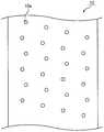
도 2a 는, 비편광부의 배치 패턴의 일례를 설명하는 개략 평면도이다.
도 2b 는, 비편광부의 배치 패턴의 다른 예를 설명하는 개략 평면도이다.
도 2c 는, 비편광부의 배치 패턴의 또 다른 예를 설명하는 개략 평면도이다.
도 3 은, 본 발명의 검사 방법에 사용될 수 있는 검사 장치를 설명하는 개략도이다.
도 4 는, 본 발명의 일 실시형태에 있어서의 결함 검출의 구체적 순서를 설명하는 플로 차트이다.
도 5 는, 본 발명의 다른 실시형태에 있어서의 결함 검출의 구체적 순서를 설명하는 플로 차트이다.
도 6 은, 도 5 에서 나타낸 실시형태에 있어서의 결함 검출의 구체적 순서를 설명하는 개략도이다.1 is a schematic cross-sectional view of a polarizing plate that can be provided in the inspection method of the present invention.
2A is a schematic plan view for explaining an example of the arrangement pattern of the non-light-emitting portion.
2B is a schematic plan view for explaining another example of the arrangement pattern of the non-light-emitting portion.
2C is a schematic plan view for explaining another example of the arrangement pattern of the non-light-emitting portion.
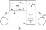
3 is a schematic view for explaining a testing apparatus which can be used in the testing method of the present invention.
Fig. 4 is a flow chart for explaining a concrete procedure of defect detection in the embodiment of the present invention.
Fig. 5 is a flow chart for explaining a concrete procedure of defect detection in another embodiment of the present invention.
Fig. 6 is a schematic view for explaining a specific order of defect detection in the embodiment shown in Fig. 5; Fig.
[A. 검사 방법 및 검사 장치][A. Inspection method and inspection apparatus]
본 발명은, 장척 방향으로 소정 간격으로 배치된 비편광부를 갖는 장척상의 편광판을, 그 장척 방향으로 반송하면서 그 외관을 검사하는 방법을 제공한다. 본 발명의 검사 방법은, 비편광부를 갖는 편광판을 촬상하여 화상 데이터를 취득하는 공정과, 그 화상 데이터를 해석하여 결함 후보부를 추출하는 공정과, 결함 후보부가 기준치 이하의 사이즈를 갖는지의 여부를 판단하는 공정과, 결함 후보부의 사이즈에 기초하여 결함을 검출하는 공정을 포함한다. 결함을 검출하는 공정에 있어서는, 예를 들어, 기준치를 초과하는 사이즈를 갖는 결함 후보부를 비편광부로 인식하여 구별하고, 기준치 이하의 사이즈를 갖는 결함 후보부를 결함으로서 검출할 수 있다.The present invention provides a method of inspecting the appearance of a polarizing plate having a non-light-emitting portion disposed at predetermined intervals in the longitudinal direction while conveying the polarizing plate in its longitudinal direction. The inspection method of the present invention includes the steps of capturing image data of a polarizing plate having a non-light-deflecting portion, extracting a defect candidate portion by analyzing the image data, judging whether or not the defect candidate portion has a size smaller than a reference value And a step of detecting a defect based on the size of the defect candidate portion. In the defect detecting step, for example, a defect candidate portion having a size exceeding a reference value can be recognized as a non-bright portion, and a defect candidate portion having a size smaller than the reference value can be detected as a defect.
본 발명의 검사 방법은, 결함 후보부가 장척 방향으로 주기성을 갖는지의 여부를 판단하는 공정을 추가로 포함할 수 있다. 이 경우, 상기 결함을 검출하는 공정에 있어서, 결함 후보부의 사이즈 및 주기성의 유무에 기초하여 결함을 검출한다. 보다 구체적으로는, 기준치 이하의 사이즈를 갖는 결함 후보부를 결함으로서 검출함과 함께, 주기성을 갖지 않는 결함 후보부도 결함으로서 검출한다. 결함 후보부를 사이즈와 주기성의 2 가지 측면에서 평가함으로써, 검사 정밀도를 향상시킬 수 있다. 검사 효율의 관점에서는, 기준치를 초과하는 사이즈를 갖는 결함 후보부에 대해서만, 주기성의 유무를 판단하는 것이 바람직하다. 이 경우, 기준치 이하의 사이즈를 갖는 모든 결함 후보부를 결함으로서 검출함과 함께, 기준치를 초과하는 사이즈를 갖는 결함 후보부에 대해서는, 주기성을 갖지 않는 것만을 결함으로서 검출한다.The inspection method of the present invention may further include a step of determining whether or not the defect candidate portion has periodicity in the longitudinal direction. In this case, in the step of detecting the defect, the defect is detected based on the presence or absence of the size and periodicity of the defect candidate portion. More specifically, a defect candidate portion having a size smaller than the reference value is detected as a defect, and a defect candidate portion having no periodicity is also detected as a defect. The inspection accuracy can be improved by evaluating the defect candidate portion in terms of the size and the periodicity. From the viewpoint of the inspection efficiency, it is preferable to determine the presence or absence of the periodicity only for the defect candidate portion having a size exceeding the reference value. In this case, all defective candidates having a size smaller than the reference value are detected as defects, and for the defect candidate portions having sizes exceeding the reference value, only defects having no periodicity are detected as defects.
A-1. 편광판A-1. Polarizer
본 발명의 검사 방법에 제공되는 편광판은 장척상이고, 장척 방향으로 소정 간격으로 배치된 비편광부를 갖는다. 그 비편광부는, 대표적으로는, 편광자에 형성된 비편광부에서 기인된다. 또한, 본 명세서에 있어서 「장척상」이란, 폭에 비해서 길이가 충분히 긴 세장 (細長) 형상을 의미하고, 예를 들어, 폭에 비해서 길이가 10 배 이상, 바람직하게는 20 배 이상의 세장 형장을 포함한다.The polarizing plate provided in the inspection method of the present invention is elongated and has a non-light-emitting portion disposed at predetermined intervals in the longitudinal direction. The non-light-emitting portion is typically caused by a non-light-emitting portion formed in the polarizer. In the present specification, the term " elongated phase " means a long elongated shape having a length sufficiently longer than the width. For example, a long elongated shape having a length of 10 times or more, .
도 1 은, 본 발명의 검사 방법에 제공될 수 있는 편광판의 개략 단면도이다. 편광판 (30) 은, 비편광부를 갖는 편광자 (10) 와, 편광자 (10) 의 양측에 배치된 보호 필름 (11, 12) 을 갖는다. 도시예에서는, 편광자의 양측에 보호 필름이 배치되어 있지만, 편측에만 보호 필름이 배치되어 있어도 된다. 혹은, 편광판은 편광자만으로 구성되어 있어도 된다 (즉, 편광판은 편광자이어도 된다).1 is a schematic cross-sectional view of a polarizing plate that can be provided in the inspection method of the present invention. The polarizing
편광자 (10) 는, 대표적으로는 이색성 물질을 함유하는 수지 필름으로 구성된다. 편광판 (30) 이 장척상인 점에서, 편광자 (10) 역시 장척상이다. 편광자 (10) 는, 장척 방향으로 소정 간격으로 배치된 비편광부를 갖는다. 일 실시형태에 있어서, 편광자 (10) 는, 장척 방향 및 폭 방향으로 소정 간격으로 배치된 비편광부를 갖는다. 비편광부의 배치 패턴은, 목적에 따라서 적절히 설정될 수 있다. 대표적으로는, 상기 비편광부는, 편광자를 소정 사이즈의 화상 표시 장치에 장착하기 위해서 소정 사이즈로 재단 (예를 들어, 장척 방향 및/또는 폭 방향으로의 절단, 타발 (打拔)) 했을 때, 그 화상 표시 장치의 카메라부에 대응하는 위치에 배치될 수 있다. 일 실시형태에 있어서는, 비편광부는 장척 방향 및 폭 방향 중 어느 방향에 있어서도 실질적으로 등간격으로 배치된다. 또한, 「장척 방향 및 폭 방향 중 어느 방향에 있어서도 실질적으로 등간격」이란, 장척 방향의 간격이 등간격이며, 또한, 폭 방향의 간격이 등간격인 것을 의미하고, 장척 방향의 간격과 폭 방향의 간격이 동등할 필요는 없다. 다른 실시형태에 있어서는, 비편광부는 장척 방향으로 실질적으로 등간격으로 배치되며, 또한, 폭 방향으로 상이한 간격으로 배치되어도 된다. 폭 방향에 있어서 비편광부가 상이한 간격으로 배치될 경우, 인접하는 비편광부의 간격은 모두 상이해도 되고, 일부 (특정한 인접하는 비편광부의 간격) 만이 상이해도 된다. 또, 편광자의 장척 방향으로 복수의 영역을 규정하고, 각각의 영역마다 장척 방향 및/또는 폭 방향에 있어서의 비편광부의 간격을 설정해도 된다.The
도 2a ∼ 도 2c 는 각각, 편광자 (10) 에 있어서의 비편광부의 배치 패턴의 일례를 설명하는 개략 평면도이다. 일 실시형태에 있어서는, 비편광부 (10a) 는, 도 2a 에 나타내는 바와 같이, 장척 방향에 있어서 인접하는 비편광부를 잇는 직선이, 장척 방향에 대해서 실질적으로 평행하고, 그리고, 폭 방향에 있어서 인접하는 비편광부를 잇는 직선이, 폭 방향에 대해서 실질적으로 평행하도록 배치된다.2A to 2C are schematic plan views for explaining an example of the arrangement pattern of the non-light-emitting portion in the
비편광부를 평면에서 보았을 때의 형상은, 목적에 따라서 임의의 적절한 형상이 채용될 수 있다. 예를 들어, 비편광부를 평면에서 보았을 때의 형상은, 편광자가 사용되는 화상 표시 장치의 카메라 성능에 악영향을 주지 않는 한에 있어서, 임의의 적절한 형상이 채용될 수 있다. 도시예의 비편광부는 원형이지만, 예를 들어, 타원형, 정방형, 사각형, 마름모꼴 등으로 형성되어 있어도 된다.The shape of the non-light-emitting portion when viewed in a plane may be any suitable shape depending on the purpose. For example, the shape of the non-light-emitting portion viewed from the plane may be any arbitrary shape as long as it does not adversely affect the camera performance of the image display device in which the polarizer is used. The non-light-emitting portion in the illustrated example is circular but may be formed, for example, in an elliptical shape, a square shape, a square shape, or a diamond shape.
비편광부의 투과율 (예를 들어, 23 ℃ 에 있어서의 파장 550 ㎚ 의 광으로 측정한 투과율) 은, 바람직하게는 50 % 이상이고, 보다 바람직하게는 60 % 이상이며, 더욱 바람직하게는 75 % 이상이고, 특히 바람직하게는 90 % 이상이다. 이와 같은 투과율이면, 예를 들어, 비편광부가 화상 표시 장치의 카메라부에 대응하도록 편광자를 배치했을 경우, 카메라의 촬영 성능에 대한 악영향을 방지할 수 있다.The transmittance of the non-light-emitting portion (for example, the transmittance measured at a wavelength of 550 nm at 23 캜) is preferably 50% or more, more preferably 60% or more, and still more preferably 75% , And particularly preferably 90% or more. With such a transmittance, for example, when the polarizer is arranged so that the non-polarized portion corresponds to the camera portion of the image display apparatus, adverse effects on the photographing performance of the camera can be prevented.
비편광부는 임의의 적절한 형태일 수 있다. 일 실시형태에 있어서는, 비편광부는 부분적으로 탈색된 탈색부이다. 탈색부는, 예를 들어, 레이저 조사 또는 화학 처리에 의해서 형성된다. 다른 실시형태에 있어서는, 비편광부는 관통공이다. 관통공은, 예를 들어, 기계적 타발 (예를 들어, 펀칭, 톰슨날 타발, 플로터, 워터 제트) 또는 소정 부분의 제거 (예를 들어, 레이저 어블레이션 또는 화학적 용해) 에 의해서 형성된다.The non-light-emitting portion may be in any suitable form. In one embodiment, the non-light-emitting portion is a partially decolored decoloring portion. The decoloring portion is formed, for example, by laser irradiation or chemical treatment. In another embodiment, the non-light-emitting portion is a through hole. The through-hole is formed by, for example, mechanical punching (e.g., punching, Thomson blasting, plotter, water jet) or removal of a portion of the punch (e.g., laser ablation or chemical dissolution).
보호 필름 (11, 12) 의 형성 재료로는, 예를 들어, 디아세틸셀룰로오스, 트리아세틸셀룰로오스 등의 셀룰로오스계 수지, (메트)아크릴계 수지, 시클로올레핀계 수지, 폴리프로필렌 등의 올레핀계 수지, 폴리에틸렌테레프탈레이트계 수지 등의 에스테르계 수지, 폴리아미드계 수지, 폴리카보네이트계 수지, 이것들의 공중합체 수지 등을 들 수 있다. 목적이나 원하는 구성에 따라서, 보호 필름 (11, 12) 의 일방은 생략해도 된다.Examples of the material for forming the
보호 필름의 두께는, 대표적으로는 10 ㎛ ∼ 100 ㎛ 이다. 보호 필름은, 대표적으로는 접착층 (구체적으로는, 접착제층, 점착제층) 을 개재하여 편광자에 적층된다. 접착제층은, 대표적으로는 PVA 계 접착제나 활성 에너지선 경화형 접착제로 형성된다. 점착제층은, 대표적으로는 아크릴계 점착제로 형성된다.The thickness of the protective film is typically 10 占 퐉 to 100 占 퐉. Typically, the protective film is laminated on the polarizer via an adhesive layer (specifically, an adhesive layer and a pressure-sensitive adhesive layer). The adhesive layer is typically formed of a PVA adhesive or an active energy ray curable adhesive. The pressure-sensitive adhesive layer is typically formed of an acrylic pressure-sensitive adhesive.
실용적으로는, 편광판 (30) 은, 최외층으로서 점착제층 (13) 을 갖는다. 점착제층 (13) 은, 대표적으로는 화상 표시 장치측의 최외층이 된다. 점착제층 (13) 에는, 세퍼레이터 (14) 가 박리 가능하게 임시 부착되고, 실제의 사용까지 점착제층을 보호함과 함께, 롤 형성을 가능하게 하고 있다.Practically, the
편광판 (30) 은, 목적에 따라서 임의의 적절한 광학 기능층을 추가로 갖고 있어도 된다. 광학 기능층의 대표예로는, 위상차 필름 (광학 보상 필름), 표면 처리층을 들 수 있다. 예를 들어, 보호 필름 (12) 과 점착제층 (13) 사이에 위상차 필름이 배치될 수 있다 (도시 생략). 위상차 필름의 광학 특성 (예를 들어, 굴절률 타원체, 면내 위상차, 두께 방향 위상차) 은, 목적, 화상 표시 장치의 특성 등에 따라서 적절히 설정될 수 있다.The
표면 처리층은, 보호 필름 (11) 의 외측에 배치될 수 있다 (도시 생략). 표면 처리층의 대표예로는, 하드 코트층, 반사 방지층, 안티글레어층을 들 수 있다. 표면 처리층은, 예를 들어, 편광자의 가습 내구성을 향상시킬 목적에서 투습도가 낮은 층인 것이 바람직하다. 표면 처리층을 형성하는 대신에, 보호 필름 (11) 의 표면에 동일한 표면 처리를 실시해도 된다.The surface treatment layer can be disposed outside the protective film 11 (not shown). Typical examples of the surface treatment layer include a hard coat layer, an antireflection layer, and an antiglare layer. The surface treatment layer is preferably a layer having a low moisture permeability for the purpose of improving the damping durability of the polarizer, for example. Instead of forming the surface treatment layer, the surface of the
A-2. 검사 장치A-2. Inspection device
도 3 은, 본 발명의 검사 방법에 사용될 수 있는 검사 장치를 설명하는 개략도이다. 도시한 실시형태에 있어서는, 장척상의 편광판 (30) 이 검사 장치 (100) 에 반송되어 외관 검사가 행해진다. 검사 장치 (100) 는, 편광판 (30) 을 촬상하여 화상 데이터를 취득하는 촬상 장치 (50) 와, 얻어진 화상 데이터를 해석하여 그 편광판 (30) 의 결함을 검출하는 화상 해석 장치 (80) 를 구비한다. 화상 해석 장치 (80) 는, 얻어진 화상 데이터에 기초하여 결함 후보부를 추출하는 결함 후보부 추출부 (82) 와, 결함 후보부가 기준치 이하의 사이즈를 갖는지의 여부를 판단하는 사이즈 판단부 (84) 와, 결함 후보부가 장척 방향으로 주기성을 갖는지의 여부를 판단하는 주기성 판단부 (86) 와, 결함 후보부의 사이즈, 또는, 결함 후보부의 사이즈와 주기성의 유무에 기초하여 결함을 검출하는 결함 검출부 (88) 를 갖는다.3 is a schematic view for explaining a testing apparatus which can be used in the testing method of the present invention. In the illustrated embodiment, the long polarizing
A-3. 화상 데이터를 취득하는 공정 (1)A-3. Step (1) of obtaining image data
공정 (1) 은, 촬상 장치 (50) 를 사용하여, 상기 비편광부를 갖는 편광판을 촬상하여 화상 데이터를 얻음으로써 행해질 수 있다. 촬상 장치 (50) 는, 대표적으로는 조명부 (52) 와 촬상부 (54) 를 구비한다.The step (1) can be performed by using the
조명부 (52) 는, 임의의 적절한 광원을 사용하여 구성될 수 있다. 광원은 백색 광원이어도 되고, 단색 광원이어도 된다. 광원의 구체예로는, 형광등, 할로겐 램프, 메탈 할라이드 램프, LED 등을 들 수 있다.The
촬상부 (54) 는, 대표적으로는, 렌즈 및 이미지 센서를 사용하여 구성된 카메라이다. 촬상부는, 바람직하게는 편광판의 전체 폭을 촬상할 수 있도록 1 개 또는 복수 형성된다. 또, 촬상부는, 바람직하게는 장척 방향으로 연속된 화상을 촬상할 수 있도록 되어 있다. 일 실시형태에 있어서, 촬상부는 라인 센서 카메라이다.The
도 3 에 나타내는 실시형태에 있어서는, 상기 편광판의 일방의 측에 배치된 조명부 (52) 로부터 편광판 (30) 에 대해서 광을 조사하고, 편광판 (30) 의 타방의 측에 조명부 (52) 와 대향하도록 배치된 촬상부 (54) 에 의해서 편광판 (30) 을 투과한 광을 촬상한다. 투과광을 촬상함으로써, 비편광부에 대응하는 영역의 휘도가, 다른 부분에 대응하는 영역의 휘도보다 높은 이미지가 얻어질 수 있다.3, light is irradiated to the
다른 실시형태 (도시 생략) 에 있어서는, 상기 편광판의 일방의 측에 조명부와 촬상부를 배치하고, 그 조명부로부터 편광판에 대해서 경사 방향으로부터 광을 조사하여, 조명부와 동일한 측에 배치된 촬상부에 의해서 편광판에 반사된 광을 촬상한다.In another embodiment (not shown), an illumination section and an image pickup section are arranged on one side of the polarizing plate, light is irradiated from the illumination section to the polarizing plate in an oblique direction, and the polarizing plate As shown in Fig.
또 다른 실시형태 (도시 생략) 에 있어서는, 상기 편광판의 일방의 측에 조명부와 촬상부를 배치하고, 그 촬상부의 카메라의 광축과 조사광의 광축이 일치하도록, 편광판에 대해서 수직으로 광을 조사하여, 그 반사광을 촬상한다.In another embodiment (not shown), an illumination section and an imaging section are arranged on one side of the polarizing plate, light is irradiated perpendicularly to the polarizing plate so that the optical axis of the camera of the imaging section and the optical axis of the irradiation light are aligned, And picks up reflected light.
비편광부의 형태 (탈색부, 관통공 등), 편광판의 구성 등에 따라서 적절한 촬상 방법을 선택하여 편광판을 촬상함으로써, 비편광부에 대응하는 영역의 휘도와 그 밖의 부분에 대응하는 영역의 휘도의 차가 큰 (결과적으로, 콘트라스트비가 큰) 화상이 얻어질 수 있다. 편광판의 촬상은, 상기 실시형태의 어느 하나에 따라서 행해져도 되고, 2 개 이상의 실시형태를 조합하여 행해도 된다.By picking up a proper polarizing plate by selecting an appropriate imaging method in accordance with the shape of the non-light emitting portion (decoloring portion, through hole, etc.) and the configuration of the polarizing plate, the difference between the brightness of the region corresponding to the non- (Consequently, a large contrast ratio) image can be obtained. The image pickup of the polarizing plate may be performed according to any one of the above-described embodiments, or two or more embodiments may be combined.
바람직하게는, 장척상의 편광판을 장척 방향으로 반송하면서 촬상을 행한다. 반송하면서 촬상을 행함으로써, 제조 라인의 정지를 회피하여 제조 효율을 유지할 수 있다.Preferably, imaging is carried out while conveying the long polarizing plate in the longitudinal direction. By performing imaging while conveying, the manufacturing efficiency can be maintained by avoiding the stoppage of the production line.
A-4. 결함 후보부를 추출하는 공정 (2)A-4. Step (2) of extracting a defect candidate portion
촬상 장치 (50) 에 의해서 얻어진 화상 데이터는, 전기 신호로서 화상 해석 장치 (80) 에 송신된다. 송신된 화상 데이터는, 결함 후보부 추출부 (82) 에 의해서 해석되고, 이로써 결함 후보부가 추출된다.The image data obtained by the
일 실시형태에 있어서는, 화상 데이터의 휘도 정보에 기초하여 결함 후보부를 추출한다. 구체적으로는, 미리 정상적인 편광판을 촬상하여 정상으로 판정되는 휘도 기준을 설정하고, 그 기준에 기초하여 결함 후보부를 추출한다. 예를 들어, 정상으로 판정되는 휘도의 상한을 초과하는 고휘도부, 정상으로 판정되는 휘도의 하한을 초과하는 저휘도부 등을 결함 후보부로 판정할 수 있다. 이물질, 기포, 핀홀 등의 외관 불량의 원인이 되는 결함부는, 통상적으로 편광판의 정상 영역과 투과율, 반사율 등이 상이한 점에서, 상기와 같은 휘도 기준에 의해서 결함 후보부로서 추출된다. 한편, 얻어진 화상 데이터에 있어서는, 비편광부에 대응하는 영역도, 그 밖의 부분에 대응하는 영역과 투과율, 반사율 등이 상이한 점에서 결함 후보부로서 추출될 수 있다.In one embodiment, the defect candidate portion is extracted based on the luminance information of the image data. Specifically, a brightness reference which is determined to be normal by imaging a normal polarizing plate in advance is set in advance, and a defect candidate portion is extracted based on the reference. For example, the defect candidate portion can be determined as a high luminance portion exceeding the upper limit of the luminance determined to be normal, a low luminance portion exceeding the lower limit of the luminance determined to be normal, and the like. Defects that cause external defects such as foreign substances, bubbles, and pinholes are extracted as defective candidates by the above-described luminance criterion, because the transmittance and the reflectance of the normal region of the polarizing plate are different from each other. On the other hand, in the obtained image data, the region corresponding to the non-light-emitting portion can also be extracted as the defect candidate portion in that the transmittance, the reflectance, and the like are different from the region corresponding to the other portion.
결함 후보 추출부 (82) 는, 바람직하게는 결함 후보부의 위치 정보 (예를 들어, 장척 방향으로 연속된 화상에 있어서의 장척 방향 및 폭 방향의 위치 좌표 (X, Y)) 를 기억하여, 주기성 판단부 (86) 에 송신한다.Preferably, the defect
A-5. 결함 후보부가 기준치 이하의 사이즈를 갖는지의 여부를 판단하는 공정 (3)A-5. (3) judging whether or not the defect candidate portion has a size equal to or smaller than a reference value,
결함 후보부 추출부 (82) 에 의해서 결함 후보부가 추출되면, 추출된 개개의 결함 후보부에 대해서, 사이즈 판단부 (84) 에서 그 사이즈를 결정하고, 나아가서는, 그 사이즈가 기준치 이하인지의 여부를 판단한다.When the defect candidate portion is extracted by the defect candidate
결함 후보부의 사이즈의 결정은 임의의 적절한 방법에 의해서 행해질 수 있다. 예를 들어, 화상 데이터 중에 있어서의 결함 후보부의 화소수, 직경, 면적 등에 기초하여 사이즈를 결정할 수 있다. 결함 후보부의 직경은, 대표적으로는 화상 데이터에 있어서, 결함 후보부의 외주상의 임의의 2 점을 잇는 직선 중, 가장 긴 것의 길이가 직경으로서 결정될 수 있다. 면적은 화소수 또는 직경에 기초하여 산출될 수 있다.The determination of the size of the defect candidate portion can be made by any suitable method. For example, the size can be determined based on the number of pixels, diameter, area, etc. of the defect candidate portion in the image data. The diameter of the defect candidate portion can be typically determined as the diameter of the longest straight line connecting arbitrary two points on the outer circumference of the defect candidate portion in the image data. The area can be calculated based on the number of pixels or the diameter.
상기 기준치는, 임의의 적절한 방법에 의해서 결정될 수 있다. 예를 들어, 상기 기준치는, 비편광부의 사이즈에 기초하여 결정될 수 있다. 예를 들어, 직경에 의해서 사이즈를 판단하는 경우, 상기 기준치 (직경의 기준치) 는, 이하와 같이 하여 결정할 수 있다. 즉, 설계상의 비편광부의 형상 및 치수에 기초하여 비편광부의 직경 (이론치) 을 산출하거나, 혹은, 실제로 편광자에 형성된 비편광부의 직경 (실측치) 을 측정하고, 얻어진 비편광부의 직경의 예를 들어 90 %, 바람직하게는 95 % 를 기준치로 할 수 있다. 또, 예를 들어, 결함의 평균 사이즈가 비편광부의 사이즈에 비해서 충분히 작을 경우 (예를 들어, 결함의 평균 직경이 비편광부의 직경의 1/8 이하인 경우), 상기 기준치는, 비편광부의 직경의 1/4 ∼ 1/2 의 값으로 할 수 있다. 구체예로서, 비편광부의 직경이 2800 ㎛ 정도이고, 결함의 평균 직경이 150 ㎛ ∼ 300 ㎛ 인 경우, 상기 기준치를 1000 ㎛ 정도로 할 수 있다.The reference value may be determined by any suitable method. For example, the reference value may be determined based on the size of the non-light-emitting portion. For example, when the size is determined by the diameter, the reference value (reference value of the diameter) can be determined as follows. That is, the diameter (theoretical value) of the non-bright portion is calculated on the basis of the shape and the dimension of the non-light portion in design, or the diameter (actual measurement value) of the non-bright portion actually formed on the polarizer is measured. 90%, preferably 95% of the reference value. For example, when the average size of the defects is sufficiently smaller than the size of the non-light-emitting portion (for example, when the average diameter of the defect is 1/8 or less of the diameter of the non-light portion) The value can be set to 1/4 to 1/2. As a specific example, when the diameter of the non-light-emitting portion is about 2800 占 퐉 and the average diameter of defects is 150 占 퐉 to 300 占 퐉, the reference value can be set to about 1000 占 퐉.
A-6. 결함 후보부가 그 장척 방향으로 주기성을 갖는지의 여부를 판단하는 공정 (4)A-6. (4) of judging whether or not the defect candidate section has a periodicity in its longitudinal direction,
주기성 판단부 (86) 는, 추출된 결함 후보부 전체를 주기성의 판단 대상으로 해도 되고, 사이즈 판단부 (84) 에 있어서 기준치를 초과하는 사이즈를 갖는 것이 확인된 결함 후보부만을 판단 대상으로 해도 된다. 바람직하게는, 사이즈 판단부 (84) 에 있어서 기준치를 초과하는 사이즈를 갖는 것이 확인된 결함 후보부만을 판단 대상으로 한다.The
일 실시형태에 있어서는, 3 개 이상의 결함 후보부가 임의의 방향으로 연장되는 직선 상에 등간격으로 존재할 때, 이들 결함 후보부는 주기성을 갖는다고 판단할 수 있다.In one embodiment, when three or more defect candidates exist at regular intervals on a straight line extending in an arbitrary direction, these defect candidates can be judged to have periodicity.
검사 대상의 편광판에 있어서는, 적어도 장척 방향으로 소정 간격으로 비편광부가 배치되어 있는 점에서, 장척 방향에 있어서의 비편광부 사이의 간격에 기초하여 주기성을 판단할 수 있다. 따라서, 편광판 표면에 있어서의 판단 대상인 결함 후보부의 위치를 결정하고, 상기 소정 간격으로 존재하는 것을 스크리닝하거나 함으로써, 주기성의 유무를 효율적으로 판단할 수 있다.In the polarizing plate to be inspected, the periodicity can be determined based on the interval between the non-polarized portions in the longitudinal direction, since the non-polarized light portion is arranged at a predetermined interval in at least the longitudinal direction. Therefore, the presence or absence of the periodicity can be efficiently determined by determining the position of the defect candidate portion to be determined on the surface of the polarizing plate, and screening what exists at the predetermined interval.
일 실시형태에 있어서는, 결함 후보부의 주기성 유무의 판단은, 결함 후보부의 위치 좌표 (예를 들어, 장척 방향에 있어서의 위치 좌표) 에 기초하여 행해진다. 예를 들어, 결함 후보부 추출부로부터 송신되는 결함 후보부 (예를 들어 장척 방향으로 2 개 이상, 바람직하게는 3 개 이상 인접하는 결함 후보부) 의 위치 좌표를, 설계상 (이론상) 의 비편광부의 위치 좌표와 대조하여 위치 좌표가 일치한 경우에는, 그 결함 후보부는 주기성을 갖는다고 판단할 수 있다. 또, 예를 들어, 결함 후보부 추출부로부터 송신되는 결함 후보부의 장척 방향의 위치 좌표에 기초하여, 판단 대상인 결함 후보부와, 그 반송 방향 상류측에 존재하는 비편광부 (결함은 아니라고 판단 완료된 결함 후보부일 수 있다) 의 장척 방향의 거리를 구하고, 그 거리가 소정 거리인지의 여부에 기초하여 행해진다. 그 거리는, 예를 들어, 장척 방향에 있어서의 비편광부의 배치 간격 (즉, 상기 장척 방향에 있어서의 소정 간격), 또는, 그 소정 간격을 정수배한 거리일 수 있다.In one embodiment, the determination of the periodicity of the defect candidate portion is made based on the position coordinates of the defect candidate portion (e.g., positional coordinates in the longitudinal direction). For example, the position coordinates of a defect candidate portion (for example, two or more, preferably three or more contiguous defect candidate portions in the longitudinal direction) transmitted from the defect candidate portion extraction portion may be referred to as a special When the position coordinates are matched with the position coordinates of the light portion, the defect candidate portion can be judged to have periodicity. In addition, for example, based on the position coordinates in the longitudinal direction of the defect candidate portion transmitted from the defect candidate portion extracting portion, the defect candidate portion to be determined and the non-light-emitting portion on the upstream side in the carrying direction And the distance is determined based on whether the distance is a predetermined distance or not. The distance may be, for example, an arrangement interval of the non-light-emitting portions in a long direction (that is, a predetermined interval in the longitudinal direction), or a distance obtained by multiplying the predetermined interval.
A-7. 결함을 검출하는 공정 (5)A-7. Step (5) of detecting defects
결함 검출부 (88) 는, 결함 후보부의 사이즈, 또는, 결함 후보부의 사이즈와 주기성의 유무에 기초하여 결함을 검출한다. 구체적으로는, 결함 검출부 (88) 는, 사이즈 판단부 (84) 에 있어서 기준치 이하의 사이즈를 갖는다고 판단된 결함 후보부를 결함으로서 검출한다. 결함 검출부 (88) 는 또한, 주기성 판단부 (86) 에 있어서 주기성을 갖는다고 판단된 결함 후보부를 비편광부로 인식하여 결함 후보부와 구별하고, 나머지의 결함 후보부를 결함으로서 검출할 수 있다. 바꾸어 말하면, 결함 검출부 (88) 는, 기준치 이하의 사이즈를 갖는다고 판단된 결함 후보부 및 주기성을 갖지 않는다고 판단된 결함 후보부를 결함으로서 검출할 수 있다.The
도 4 는, 본 발명의 일 실시형태에 있어서의 결함 검출의 구체적 순서를 설명하는 플로 차트이다. 도 4 에 나타내는 실시형태에서는, 먼저, 편광판의 화상 데이터를 취득한다 (상기 공정 (1)). 이어서, 화상 데이터에 기초하여 결함 후보부를 추출한다 (상기 공정 (2)). 이어서, 결함 후보부가 기준치 이하의 사이즈를 갖는지의 여부를 판단하고 (상기 공정 (3)), 기준치를 초과하는 사이즈를 갖는 결함 후보부를 비편광부로 판단하는 한편, 기준치 이하의 사이즈를 갖는 결함 후보부를 결함으로서 검출한다 (상기 공정 (5)).Fig. 4 is a flow chart for explaining a concrete procedure of defect detection in the embodiment of the present invention. In the embodiment shown in Fig. 4, first, the image data of the polarizing plate is acquired (the above step (1)). Subsequently, the defect candidate portion is extracted based on the image data (the above step (2)). Next, it is judged whether or not the defect candidate portion has a size equal to or smaller than the reference value (the above step (3)), and the defect candidate portion having the size exceeding the reference value is determined as the non- (Step (5)).
도 5 는, 본 발명의 다른 실시형태에 있어서의 결함 검출의 구체적 순서를 설명하는 플로 차트이다. 도 5 에 나타내는 실시형태에서는, 먼저, 편광판의 화상 데이터를 취득한다 (상기 공정 (1)). 이어서, 화상 데이터에 기초하여 결함 후보부를 추출한다 (상기 공정 (2)). 이어서, 결함 후보부가 기준치 이하의 사이즈를 갖는지의 여부를 판단하고 (상기 공정 (3)), 기준치를 초과하는 사이즈를 갖는 결함 후보부에 대해서, 주기성의 유무를 판단한다 (상기 공정 (4)). 얻어진 결과에 기초하여, 기준치 이하의 사이즈를 갖는 결함 후보부 및 기준치를 초과하는 사이즈를 갖지만, 주기성을 갖지 않는 결함 후보부를 결함으로서 검출한다 (상기 공정 (5)). 또한, 도 6(a) 중의 백색 원은, 당해 실시형태에 의한 공정 (2) 에 있어서 추출된 모든 결함 후보부를 나타내고, 도 6(b) 중의 백색 원은, 기준치를 초과하는 사이즈를 갖고, 주기성 유무의 판단 대상이 되는 결함 후보부를 나타내며, 도 6(c) 중의 흑색 원은 주기성을 갖는다고 판단된 결함 후보부 (비편광부) 를 나타내고, 백색 원은 주기성을 갖지 않는다고 판단된 결함 후보부 (결함) 를 나타내고, 도 6(d) 중의 백색 원은 최종적으로 검출되는 결함을 나타낸다.Fig. 5 is a flow chart for explaining a concrete procedure of defect detection in another embodiment of the present invention. In the embodiment shown in Fig. 5, first, the image data of the polarizing plate is acquired (the above step (1)). Subsequently, the defect candidate portion is extracted based on the image data (the above step (2)). Then, it is judged whether or not the defect candidate portion has a size equal to or smaller than the reference value (step (3)), and the presence or absence of the periodicity is judged for the defect candidate portion having a size exceeding the reference value (the step (4) . Based on the obtained results, a defect candidate portion having a size smaller than the reference value and a defect candidate portion having a size exceeding the reference value but not having a periodicity are detected as defects (the above step (5)). The white circle in Fig. 6 (a) represents all the defect candidates extracted in the step (2) according to the embodiment, the white circle in Fig. 6 (b) has a size exceeding the reference value, The black circles in FIG. 6 (c) indicate defective candidates judged to have periodicity (non-bright portions), and the white circles indicate defective candidates judged not to have periodicity ), And a white circle in Fig. 6 (d) represents a defect finally detected.
A-8. 마킹 공정 (6)A-8. Marking process (6)
검사 장치 (100) 는, 마킹 장치 (도시 생략) 를 추가로 구비하고 있어도 된다. 마킹 장치는, 화상 처리 장치와 접속되어, 화상 처리 장치 (실질적으로는 결함 검출부) 가 결함을 검출하면, 그 결함의 위치 정보를 마킹 장치에 송신한다. 마킹 장치는, 그 위치 정보에 기초하여 결함부에 마킹을 행한다. 마킹된 영역은, 재단 후에 불량 편광판으로서 용이하게 배제될 수 있다. 마킹으로는, 마커 펜을 사용한 마킹이나 레이저 마킹을 들 수 있다.The
[B. 편광판의 제조 방법][B. Polarizing plate production method]
본 발명의 비편광부를 갖는 편광자를 포함하는 장척상의 편광판의 제조 방법은, 장척상의 편광자에 비편광부를 형성하는 것, 그 비편광부를 갖는 장척상의 편광자를 사용하여 편광판을 제조하는 것, 및, 상기 검사 방법에 의해서 편광판의 외관을 검사하는 것을 포함한다.A method of producing a long polarizing plate including a polarizer having a non-light-deflecting portion of the present invention is characterized in that a non-light-emitting portion is formed in a long-axis polarizer, a polarizing plate is produced using a long-angle polarizer having the light- And inspecting the appearance of the polarizing plate by an inspection method.
B-1. 편광자B-1. Polarizer
편광자는, 대표적으로는 이색성 물질을 함유하는 수지 필름으로 구성된다. 이색성 물질로는, 예를 들어, 요오드, 유기 염료 등을 들 수 있다. 이것들은 단독으로, 또는 2 종 이상 조합하여 사용될 수 있다. 바람직하게는 요오드가 사용된다.The polarizer is typically composed of a resin film containing a dichroic substance. Examples of the dichroic material include iodine and organic dyes. These may be used alone or in combination of two or more. Iodine is preferably used.
상기 수지 필름을 형성하는 수지로는, 임의의 적절한 수지가 사용될 수 있다. 바람직하게는, 폴리비닐알코올계 수지가 사용된다. 폴리비닐알코올계 수지로는, 예를 들어, 폴리비닐알코올, 에틸렌-비닐알코올 공중합체를 들 수 있다. 폴리비닐알코올은, 폴리아세트산비닐을 비누화함으로써 얻어진다. 에틸렌-비닐알코올 공중합체는, 에틸렌-아세트산비닐 공중합체를 비누화함으로써 얻어진다.As the resin forming the resin film, any suitable resin may be used. Preferably, a polyvinyl alcohol-based resin is used. Examples of the polyvinyl alcohol-based resin include polyvinyl alcohol and ethylene-vinyl alcohol copolymer. Polyvinyl alcohol is obtained by saponifying polyvinyl acetate. The ethylene-vinyl alcohol copolymer is obtained by saponifying an ethylene-vinyl acetate copolymer.
편광자 (비편광부를 제외한다) 는, 바람직하게는 파장 380 ㎚ ∼ 780 ㎚ 의 어느 파장에서 흡수 이색성을 나타낸다. 편광자 (비편광부를 제외한다) 의 단체 투과율은, 바람직하게는 39 % 이상, 보다 바람직하게는 39.5 % 이상, 더욱 바람직하게는 40 % 이상, 특히 바람직하게는 40.5 % 이상이다. 또한, 단체 투과율의 이론상의 상한은 50 % 이고, 실용적인 상한은 46 % 이다. 또, 단체 투과율은 JIS Z8701 의 2 도 시야 (C 광원) 에 의해서 측정하여 시감도 보정을 행한 Y 값으로서, 예를 들어, 현미 분광 시스템 (람다 비전 제조 LVmicro) 을 사용하여 측정할 수 있다. 편광자의 편광도 (비편광부를 제외한다) 는, 바람직하게는 99.9 % 이상, 보다 바람직하게는 99.93 % 이상, 더욱 바람직하게는 99.95 % 이상이다.The polarizer (excluding the non-light-emitting portion) preferably exhibits absorption dichroism at a wavelength of 380 nm to 780 nm. The transmittance of the polarizer (excluding the non-light-emitting portion) is preferably 39% or more, more preferably 39.5% or more, still more preferably 40% or more, particularly preferably 40.5% or more. Further, the theoretical upper limit of the simple transmittance is 50%, and the practical upper limit is 46%. The unit transmissivity can be measured using a microscopic spectroscopy system (manufactured by Lambda Vision LVmicro) as a Y value obtained by performing visibility correction by measuring with a 2-degree field of view (C light source) of JIS Z8701. The degree of polarization (excluding the non-light-emitting portion) of the polarizer is preferably not less than 99.9%, more preferably not less than 99.93%, further preferably not less than 99.95%.
편광자의 두께는, 임의의 적절한 값으로 설정될 수 있다. 두께는, 바람직하게는 30 ㎛ 이하, 보다 바람직하게는 25 ㎛ 이하, 더욱 바람직하게는 20 ㎛ 이하, 특히 바람직하게는 10 ㎛ 이하이다. 한편으로, 두께는, 바람직하게는 0.5 ㎛ 이상, 더욱 바람직하게는 1 ㎛ 이상이다.The thickness of the polarizer can be set to any suitable value. The thickness is preferably 30 占 퐉 or less, more preferably 25 占 퐉 or less, further preferably 20 占 퐉 or less, particularly preferably 10 占 퐉 or less. On the other hand, the thickness is preferably 0.5 占 퐉 or more, and more preferably 1 占 퐉 or more.
편광자의 흡수축은, 목적에 따라서 임의의 적절한 방향으로 설정될 수 있다. 흡수축의 방향은, 예를 들어 장척 방향이어도 되고 폭 방향이어도 된다. 장척 방향으로 흡수축을 갖는 편광자는, 예를 들어, 제조 효율이 우수하다는 이점이 있다. 폭 방향으로 흡수축을 갖는 편광자는, 예를 들어, 장척 방향으로 지상축을 갖는 위상차 필름과 롤 투 롤로 적층할 수 있다는 이점이 있다. 일 실시형태에 있어서는, 흡수축은 장척 방향 또는 폭 방향으로 실질적으로 평행하며, 또한, 편광자의 폭 방향 양단은 장척 방향으로 평행하게 슬릿 가공되어 있다. 이와 같은 구성에 의하면, 편광자의 단변 (端邊) 을 기준으로 재단할 수 있고, 원하는 위치에 비편광부를 가지며, 또한 적절한 방향으로 흡수축을 갖는 복수의 편광자를 용이하게 제조할 수 있다. 또한, 편광자의 흡수축은, 후술하는 연신 처리에 있어서의 연신 방향에 대응할 수 있다.The absorption axis of the polarizer can be set in any appropriate direction depending on the purpose. The direction of the absorption axis may be, for example, a long direction or a width direction. The polarizer having an absorption axis in the longitudinal direction has an advantage of, for example, excellent manufacturing efficiency. The polarizer having the absorption axis in the width direction is advantageous in that it can be laminated with a roll-to-roll film and a retardation film having a slow axis in the longitudinal direction, for example. In one embodiment, the absorption axis is substantially parallel to the longitudinal direction or width direction, and both widthwise ends of the polarizer are slit parallel to the longitudinal direction. According to such a configuration, it is possible to easily manufacture a plurality of polarizers which can be cut with respect to the side edge of the polarizer, have a non-light-emitting portion at a desired position, and have an absorption axis in an appropriate direction. The absorption axis of the polarizer may correspond to the stretching direction in a stretching process to be described later.
편광자는, 대표적으로는 상기 수지 필름에 팽윤 처리, 연신 처리, 상기 이색성 물질에 의한 염색 처리, 가교 처리, 세정 처리, 건조 처리 등의 각종 처리를 실시함으로써 얻어진다. 각종 처리를 실시할 때, 수지 필름은 기재 상에 형성된 수지층이어도 된다. 상기 비편광부의 형성은, 편광자의 제조 공정 도중이어도 행할 수 있다.Typically, the polarizer is obtained by subjecting the resin film to various treatments such as swelling treatment, stretching treatment, dyeing treatment with the dichroic substance, crosslinking treatment, washing treatment, and drying treatment. When various treatments are carried out, the resin film may be a resin layer formed on a substrate. The formation of the non-light-emitting portion can also be performed during the production process of the polarizer.
B-2. 비편광부의 형성B-2. Formation of non-light-emitting part
바람직하게는 비편광부는 탈색부이다. 이와 같은 구성에 의하면, 기계적으로 (예를 들어, 톰슨날 타발, 플로터, 워터 제트 등을 사용하여 기계적으로 빼내는 방법에 의해서) 관통공이 형성되어 있는 경우에 비해서, 크랙, 디라미네이션 (층간 박리), 접착 물질의 비어져 나옴 등의 품질상의 문제가 회피된다. 탈색부는, 바람직하게는, 편광자 (이색성 물질을 함유하는 수지 필름) 의 원하는 위치에 염기성 용액을 접촉시킴으로써 형성된다. 이와 같은 방법에 의해서 형성되는 비편광부는, 다른 부위 (비접촉부) 보다 이색성 물질의 함유량이 낮은 저농도부가 될 수 있다. 저농도부는 이색성 물질 자체의 함유량이 낮기 때문에, 레이저광 등에 의해서 이색성 물질을 분해하여 탈색부가 형성되어 있는 경우에 비해서, 비편광부의 투명성이 양호하게 유지된다.Preferably, the non-light-emitting portion is a decoloring portion. According to such a structure, cracks, delamination (delamination), and delamination (delamination) can be prevented, as compared with the case where the through holes are formed mechanically (for example, by mechanically extracting using a Thomson blade, a plotter or a water jet) Quality problems such as the release of the adhesive material are avoided. The decoloring portion is preferably formed by contacting a basic solution to a desired position of a polarizer (a resin film containing a dichroic substance). The non-light-emitting portion formed by such a method can be added at a low concentration with a lower content of a dichroic substance than other portions (non-contact portions). Since the low-density portion has a low content of the dichroic material itself, the transparency of the non-light-emitting portion is satisfactorily maintained as compared with the case where the dichromatic material is decomposed by laser light or the like to form a decolorized portion.
상기 저농도부의 이색성 물질의 함유량은, 바람직하게는 1.0 중량% 이하, 보다 바람직하게는 0.5 중량% 이하, 더욱 바람직하게는 0.2 중량% 이하이다. 저농도부의 이색성 물질의 함유량의 하한치는, 통상적으로 검출 한계치 이하이다. 상기 다른 부위에 있어서의 이색성 물질의 함유량과 저농도부에 있어서의 이색성 물질의 함유량의 차는, 바람직하게는 0.5 중량% 이상, 더욱 바람직하게는 1 중량% 이상이다. 이색성 물질로서 요오드를 사용하는 경우, 요오드 함유량은, 예를 들어, 형광 X 선 분석으로 측정한 X 선 강도로부터, 미리 표준 시료를 사용하여 작성한 검량선에 의해서 구해진다.The content of the dichroic substance in the low density portion is preferably 1.0% by weight or less, more preferably 0.5% by weight or less, and still more preferably 0.2% by weight or less. The lower limit value of the content of the dichroic substance in the low density portion is usually not more than the detection limit value. The difference between the content of the dichroic substance in the other region and the content of the dichroic substance in the low concentration region is preferably 0.5% by weight or more, more preferably 1% by weight or more. When iodine is used as the dichroic substance, the iodine content is determined from a calibration curve prepared in advance using a standard sample from the X-ray intensity measured by, for example, fluorescent X-ray analysis.
상기 염기성 용액에 함유되는 염기성 화합물로는, 임의의 적절한 화합물이 사용될 수 있다. 염기성 화합물로는, 예를 들어, 수산화나트륨, 수산화칼륨, 수산화리튬 등의 알칼리 금속의 수산화물, 수산화칼슘 등의 알칼리 토금속의 수산화물, 탄산나트륨 등의 무기 알칼리 금속염, 아세트산나트륨 등의 유기 알칼리 금속염, 암모니아수 등을 들 수 있다. 이 중에서도, 바람직하게는 알칼리 금속 및/또는 알칼리 토금속의 수산화물이 사용되고, 더욱 바람직하게는 수산화나트륨, 수산화칼륨, 수산화리튬이 사용된다. 이색성 물질을 효율적으로 이온화할 수 있고, 보다 간편하게 탈색부를 형성할 수 있다. 이들 염기성 화합물은 단독으로 사용해도 되고, 2 종 이상을 조합하여 사용해도 된다.As the basic compound contained in the basic solution, any suitable compound can be used. Examples of the basic compound include hydroxides of alkali metals such as sodium hydroxide, potassium hydroxide and lithium hydroxide; hydroxides of alkaline earth metals such as calcium hydroxide; inorganic alkali metal salts such as sodium carbonate; organic alkali metal salts such as sodium acetate; . Of these, hydroxides of alkali metals and / or alkaline earth metals are preferably used, and sodium hydroxide, potassium hydroxide and lithium hydroxide are more preferably used. The dichroic substance can be efficiently ionized and the decolorized portion can be formed more easily. These basic compounds may be used alone or in combination of two or more.
염기성 용액의 용매로는, 물, 알코올이 바람직하게 사용된다. 염기성 용액의 농도는, 예를 들어 0.01 N ∼ 5 N 이고, 바람직하게는 0.05 N ∼ 3 N 이며, 더욱 바람직하게는 0.1 N ∼ 2.5 N 이다. 염기성 용액의 액온은, 예를 들어 20 ℃ ∼ 50 ℃ 이다. 염기성 용액의 접촉 시간은, 편광자의 두께, 염기성 용액에 함유되는 염기성 화합물의 종류나 농도에 따라서 설정될 수 있다. 접촉 시간은, 예를 들어 5 초 ∼ 30 분이고, 바람직하게는 5 초 ∼ 5 분이다.As a solvent for the basic solution, water and alcohol are preferably used. The concentration of the basic solution is, for example, 0.01 N to 5 N, preferably 0.05 N to 3 N, and more preferably 0.1 N to 2.5 N. The liquid temperature of the basic solution is, for example, 20 ° C to 50 ° C. The contact time of the basic solution can be set according to the thickness of the polarizer, and the kind or concentration of the basic compound contained in the basic solution. The contact time is, for example, 5 seconds to 30 minutes, preferably 5 seconds to 5 minutes.
염기성 용액의 접촉 방법으로는, 임의의 적절한 방법이 채용될 수 있다. 예를 들어, 편광자에 대해서, 염기성 용액을 적하, 도공, 스프레이하는 방법, 편광자를 염기성 용액에 침지하는 방법을 들 수 있다. 염기성 용액의 접촉시에, 원하는 부위 이외에 염기성 용액이 접촉하지 않도록 임의의 적절한 보호재로 편광자를 보호해도 된다. 이와 같은 보호재로는, 예를 들어, 보호 필름, 표면 보호 필름이 사용된다. 보호 필름은, 편광자의 보호 필름으로서 그대로 이용될 수 있는 것이다. 표면 보호 필름은, 편광자의 제조시에 일시적으로 사용되는 것이다. 표면 보호 필름은, 임의의 적절한 타이밍에서 편광자로부터 제거되기 때문에, 대표적으로는 편광자에 점착제층을 개재하여 첩합 (貼合) 된다. 보호재의 다른 구체예로는, 포토레지스트 등을 들 수 있다. 또, 상기 편광자의 제조 공정에서 사용되는 기재도 보호재로서 사용할 수 있다.As a method of contacting the basic solution, any suitable method may be employed. For example, a method of dropping, coating and spraying a basic solution with respect to a polarizer, and a method of immersing a polarizer in a basic solution. Upon contact of the basic solution, the polarizer may be protected by any appropriate protection material so that the basic solution is not contacted with the desired site. As such a protective material, for example, a protective film or a surface protective film is used. The protective film can be used as it is as a protective film of a polarizer. The surface protective film is used temporarily during the production of the polarizer. Since the surface protective film is removed from the polarizer at an arbitrary suitable timing, it is typically bonded to the polarizer via the pressure-sensitive adhesive layer. Other specific examples of the protective material include a photoresist and the like. The substrate used in the production process of the polarizer may also be used as a protective material.
바람직하게는, 염기성 용액의 접촉시에, 편광자 표면은, 그 적어도 일부가 노출되도록 표면 보호 필름으로 피복되어 있다. 도시예와 같은 비편광부의 배치 패턴을 갖는 편광자는, 당해 배치 패턴에 대응하는 위치에, 원하는 비편광부 사이즈에 대응하는 작은 원형의 관통공이 형성된 표면 보호 필름을 편광자의 편측에 첩합하여 편광 필름 적층체를 준비하고, 이것에 염기성 용액을 접촉시킴으로써 제조된다. 그 때, 편광자의 또 다른 편측 (관통공이 형성된 표면 보호 필름 (제 1 보호 필름) 이 배치되어 있지 않은 측) 도 보호되어 있는 것이 바람직하다. 보호 필름이나 표면 보호 필름의 첩합은, 롤 투 롤에 의해서 행해지는 것이 바람직하다. 본 명세서에 있어서, 「롤 투 롤」이란, 롤상의 필름을 반송하면서 서로의 장척 방향을 정렬하여 적층하는 것을 말한다.Preferably, upon contact of the basic solution, the surface of the polarizer is covered with a surface protective film so that at least a part thereof is exposed. The polarizer having the arrangement pattern of the non-light-emitting portion as shown in the drawing is obtained by adhering a surface protective film having a small circular through-hole corresponding to the desired light-emitting portion size at a position corresponding to the arrangement pattern to one side of the polarizer, Is prepared, and a basic solution is brought into contact with it. At this time, it is preferable that the other side of the polarizer (the side where the through hole is formed and the surface protective film (first protective film) is not disposed) is also protected. The adhesion of the protective film or the surface protective film is preferably performed by roll-to-roll. In the present specification, the term "roll-to-roll" refers to a process of stacking films aligned in a longitudinal direction while transporting the roll-shaped film.
상기 표면 보호 필름의 형성 재료로는, 폴리에틸렌테레프탈레이트계 수지 등의 에스테르계 수지, 노르보르넨계 수지 등의 시클로올레핀계 수지, 폴리에틸렌, 폴리프로필렌 등의 올레핀계 수지, 폴리아미드계 수지, 폴리카보네이트계 수지, 이것들의 공중합체 수지 등을 들 수 있다. 바람직하게는, 에스테르계 수지 (특히, 폴리에틸렌테레프탈레이트계 수지) 이다. 탄성률이 충분히 높고, 예를 들어, 반송 및/또는 첩합시에 장력을 가해도 관통공의 변형이 잘 발생되지 않기 때문이다. 표면 보호 필름의 두께는, 대표적으로는 20 ㎛ ∼ 250 ㎛ 이고, 바람직하게는 30 ㎛ ∼ 150 ㎛ 이다.Examples of the material for forming the surface protective film include ester resins such as polyethylene terephthalate resins, cycloolefin resins such as norbornene resins, olefin resins such as polyethylene and polypropylene, polyamide resins, polycarbonate resins Resins, and copolymer resins thereof. Preferably, it is an ester-based resin (particularly, a polyethylene terephthalate-based resin). This is because the modulus of elasticity is sufficiently high and deformation of the through hole is not easily generated even when tensile force is applied at the time of carrying and / or coalescing. The thickness of the surface protective film is typically 20 占 퐉 to 250 占 퐉, preferably 30 占 퐉 to 150 占 퐉.
제 1 표면 보호 필름은, 소정 패턴으로 배치된 관통공을 갖는다. 관통공의 위치는, 비편광부가 형성되는 위치에 대응한다. 관통공의 형상은, 원하는 비편광부의 형상에 대응한다. 관통공은, 예를 들어, 기계적 타발 (예를 들어, 펀칭, 톰슨날 타발, 플로터, 워터 제트) 또는 필름의 소정 부분의 제거 (예를 들어, 레이저 어블레이션 또는 화학적 용해) 에 의해서 형성된다.The first surface protection film has through holes arranged in a predetermined pattern. The position of the through hole corresponds to the position where the non-polarized portion is formed. The shape of the through hole corresponds to the shape of the desired light-blocking portion. The through-holes are formed by, for example, mechanical punching (e.g., punching, Thomson blasting, plotter, water jet) or removal of certain portions of the film (e.g., laser ablation or chemical dissolution).
일 실시형태에 있어서는, 상기 염기성 용액은, 편광자와 접촉 후, 임의의 적절한 수단에 의해서 편광자로부터 제거된다. 이와 같은 실시형태에 의하면, 예를 들어, 편광자의 사용에 수반하는 비편광부의 투과율의 저하를 보다 확실하게 방지할 수 있다. 염기성 용액의 제거 방법의 구체예로는, 세정, 웨스 등에 의한 닦아냄 제거, 흡인 제거, 자연 건조, 가열 건조, 송풍 건조, 감압 건조 등을 들 수 있다. 바람직하게는, 염기성 용액은 세정된다. 세정에 사용하는 세정액으로는, 예를 들어, 물 (순수), 메탄올, 에탄올 등의 알코올, 및, 이것들의 혼합 용매 등을 들 수 있다. 바람직하게는, 물이 사용된다. 세정 횟수는 특별히 한정되지 않고, 복수 회 행해도 된다. 염기성 용액을 건조에 의해서 제거하는 경우, 그 건조 온도는, 예를 들어 20 ℃ ∼ 100 ℃ 이다.In one embodiment, the basic solution is removed from the polarizer by contact with the polarizer and by any suitable means. According to this embodiment, for example, it is possible to more reliably prevent a decrease in the transmittance of the non-light-emitting portion accompanying the use of the polarizer. Specific examples of the basic solution removing method include cleaning, wiping with a wax, and the like, suction removal, natural drying, heat drying, air blow drying, and vacuum drying. Preferably, the basic solution is cleaned. Examples of the cleaning liquid used for cleaning include water (pure water), alcohols such as methanol and ethanol, and mixed solvents thereof. Preferably, water is used. The number of times of cleaning is not particularly limited and may be plural times. When the basic solution is removed by drying, the drying temperature is, for example, 20 ° C to 100 ° C.
바람직하게는, 상기 염기성 용액과의 접촉 후, 염기성 용액을 접촉시킨 접촉부에 있어서, 수지 필름에 함유되는 알칼리 금속 및/또는 알칼리 토금속을 저감시킨다. 알칼리 금속 및/또는 알칼리 토금속을 저감시킴으로써, 치수 안정성이 우수한 비편광부를 얻을 수 있다. 구체적으로는, 가습 환경 하에서도 염기성 용액과의 접촉에 의해서 형성된 비편광부의 형상을 그대로 유지할 수 있다.Preferably, the alkali metal and / or alkaline earth metal contained in the resin film is reduced at the contact portion in contact with the basic solution after the contact with the basic solution. By reducing the alkali metal and / or alkaline earth metal, a non-light-emitting portion having excellent dimensional stability can be obtained. More specifically, the shape of the non-light-emitting portion formed by contact with the basic solution can be maintained as it is in a humidified environment.
염기성 용액을 접촉시킴으로써, 접촉부에 알칼리 금속 및/또는 알칼리 토금속의 수산화물이 잔존할 수 있다. 또, 염기성 용액을 접촉시킴으로써, 접촉부에 알칼리 금속 및/또는 알칼리 토금속의 금속염 (예를 들어, 붕산염) 을 생성할 수 있다. 이것들은 수산화물 이온을 생성할 수 있고, 생성된 수산화물 이온은, 접촉부 주위에 존재하는 이색성 물질 (예를 들어, 요오드 착물) 에 작용 (분해·환원) 하여 비편광 영역을 넓힐 수 있다. 따라서, 알칼리 금속 및/또는 알칼리 토금속염을 저감시킴으로써, 시간 경과적으로 비편광 영역이 넓어지는 것을 억제하여, 원하는 비편광부 형상이 유지될 수 있다고 생각할 수 있다.By contacting a basic solution, a hydroxide of an alkali metal and / or an alkaline earth metal may remain at the contact portion. In addition, by contacting a basic solution, a metal salt (for example, a borate salt) of an alkali metal and / or an alkaline earth metal can be produced at the contact portion. These can generate hydroxide ions, and the generated hydroxide ions can act on (decompose and reduce) a dichroic substance (for example, iodine complex) existing around the contact portion to widen the unpolarized region. Therefore, by reducing the alkali metal and / or alkaline earth metal salt, it can be considered that the desired non-light-shielding shape can be maintained by suppressing the widening of the unpolarized region over time.
상기 비편광부는, 알칼리 금속 및/또는 알칼리 토금속의 함유량이 3.6 중량% 이하인 것이 바람직하고, 보다 바람직하게는 2.5 중량% 이하이며, 더욱 바람직하게는 1.0 중량% 이하이고, 특히 바람직하게는 0.5 중량% 이하이다. 알칼리 금속 및/또는 알칼리 토금속의 함유량은, 예를 들어, 형광 X 선 분석에 의해서 측정한 X 선 강도로부터, 미리 표준 시료를 사용하여 작성한 검량선에 의해서 구할 수 있다.It is preferable that the content of the alkali metal and / or the alkaline earth metal is 3.6% by weight or less, more preferably 2.5% by weight or less, still more preferably 1.0% by weight or less, particularly preferably 0.5% Or less. The content of the alkali metal and / or alkaline earth metal can be determined from a calibration curve prepared using a standard sample in advance from the X-ray intensity measured by, for example, fluorescent X-ray analysis.
상기 저감시키는 방법으로는, 바람직하게는 염기성 용액과의 접촉부에 산성 용액을 접촉시키는 방법이 이용된다. 이와 같은 방법에 의하면, 산성 용액에 알칼리 금속 및/또는 알칼리 토금속을 효율적으로 이행시켜, 그 함유량을 저감시킬 수 있다. 산성 용액과의 접촉은, 상기 염기성 용액의 제거 후에 행해도 되고, 염기성 용액을 제거하지 않고 행해도 된다.As the reduction method, preferably, a method in which an acidic solution is brought into contact with a contact portion with a basic solution is used. According to this method, the alkali metal and / or the alkaline earth metal can be efficiently transferred to the acidic solution and the content thereof can be reduced. The contact with the acidic solution may be performed after the removal of the basic solution or without removing the basic solution.
상기 산성 용액에 함유되는 산성 화합물로는, 임의의 적절한 산성 화합물을 사용할 수 있다. 산성 화합물로는, 예를 들어, 염산, 황산, 질산, 불화수소 등의 무기산, 포름산, 옥살산, 시트르산, 아세트산, 벤조산 등의 유기산 등을 들 수 있다. 산성 용액에 함유되는 산성 화합물은, 이 중에서도, 바람직하게는 무기산이고, 더욱 바람직하게는 염산, 황산, 질산이다. 이들 산성 화합물은 단독으로 사용해도 되고, 2 종 이상을 조합하여 사용해도 된다.As the acidic compound contained in the acidic solution, any suitable acidic compound can be used. Examples of the acidic compound include inorganic acids such as hydrochloric acid, sulfuric acid, nitric acid and hydrogen fluoride, and organic acids such as formic acid, oxalic acid, citric acid, acetic acid and benzoic acid. Among them, the acidic compound contained in the acidic solution is preferably an inorganic acid, more preferably hydrochloric acid, sulfuric acid or nitric acid. These acidic compounds may be used alone or in combination of two or more.
산성 용액의 용매로는, 물, 알코올이 바람직하게 사용된다. 산성 용액의 농도는, 예를 들어 0.01 N ∼ 5 N 이고, 바람직하게는 0.05 N ∼ 3 N 이며, 더욱 바람직하게는 0.1 N ∼ 2.5 N 이다. 산성 용액의 액온은, 예를 들어 20 ℃ ∼ 50 ℃ 이다. 산성 용액의 접촉 시간은, 예를 들어 5 초 ∼ 5 분이다. 또한, 산성 용액의 접촉 방법은, 상기 염기성 용액의 접촉 방법과 동일한 방법이 채용될 수 있다. 또, 산성 용액은 편광자로부터 제거될 수 있다. 산성 용액의 제거 방법은, 상기 염기성 용액의 제거 방법과 동일한 방법이 채용될 수 있다.As the solvent of the acidic solution, water and alcohol are preferably used. The concentration of the acidic solution is, for example, 0.01 N to 5 N, preferably 0.05 N to 3 N, and more preferably 0.1 N to 2.5 N. The liquid temperature of the acidic solution is, for example, 20 ° C to 50 ° C. The contact time of the acidic solution is, for example, 5 seconds to 5 minutes. The contact method of the acidic solution may be the same as the contact method of the basic solution. Further, the acidic solution can be removed from the polarizer. As the method for removing the acidic solution, the same method as the method for removing the basic solution may be employed.
대표적으로는, 상기와 같이 하여 비편광부가 형성된 후 (바람직하게는, 알칼리 금속 및/또는 알칼리 토금속의 저감 후), 표면 보호 필름은 박리 제거될 수 있다.Typically, the surface protective film may be peeled off after the non-polarizing portion is formed as described above (preferably after reduction of the alkali metal and / or alkaline earth metal).
B-3. 편광판의 제조B-3. Production of Polarizer
상기와 같이 하여 얻어지는 비편광부를 갖는 장척상의 편광자는, 대표적으로는 편광자/보호 필름의 적층체를 구성하고 있다. 그 적층체는, 그대로 편광판으로서 사용할 수 있는 한편, 목적 등에 따라서, 그 적층체에 보호 필름 등의 다른 구성 부재를 적층함으로써, 최종 제품으로서의 임의의 적절한 구성을 갖는 편광판이 얻어질 수 있다. 또, 단일한 수지 필름으로 이루어지는 편광자가 얻어지는 경우도 마찬가지로, 용도 등에 따라서 그 편측 또는 양측에 보호 필름 등의 다른 구성 부재를 적층함으로써, 최종 제품으로서의 임의의 적절한 구성을 갖는 편광판이 얻어질 수 있다. 적층되는 다른 구성 부재에 대해서는, A-1 항에서 기재한 대로이다.The long-axis polarizer having the above-mentioned light-extinguishing portion thus obtained typically constitutes a laminate of a polarizer / protective film. The laminate can be used as a polarizing plate as it is, and a polarizing plate having any suitable structure as a final product can be obtained by laminating another constituent member such as a protective film to the laminate according to the purpose or the like. Also in the case where a polarizer made of a single resin film is obtained, a polarizing plate having any suitable structure as a final product can be obtained by laminating another constituent member such as a protective film on one side or both sides thereof in accordance with applications or the like. Other constituent members to be laminated are as described in A-1.
상기 다른 구성 부재의 적층은, 이른바 롤 투 롤로 행해질 수 있다.The lamination of the other constituent members can be performed in a so-called roll-to-roll manner.
B-4. 편광판의 외관 검사B-4. Appearance inspection of polarizer
상기와 같이 하여 얻어진 편광판을 A 항에 기재된 검사 방법에 제공한다. A 항에 기재된 검사 방법으로, 비편광부를 갖는 편광판의 외관을 검사함으로써, 비편광부를 결함으로서 잘못 검출하지 않고, 목적으로 하는 결함 (이물질, 기포, 핀홀 등) 을 검출할 수 있기 때문에, 검사 효율과 검사 정밀도를 고차로 양립할 수 있게 된다. 그 결과, 고품질의 편광판이, 우수한 제조 효율로 얻어질 수 있다.The polarizing plate thus obtained is provided in the inspection method described in the section A. By examining the appearance of the polarizing plate having the non-light-deflecting portion according to the inspection method described in Item A, it is possible to detect a target defect (foreign matter, bubble, pinhole, etc.) without erroneously detecting the non- And the inspection accuracy can be compatible with each other at a high level. As a result, a high-quality polarizing plate can be obtained with excellent manufacturing efficiency.
B-5. 편광판의 재단B-5. Cutting polarizer
본 발명의 편광판의 제조 방법은, 장척상의 편광판을 원하는 사이즈로 재단하는 공정을 추가로 포함할 수 있다. 재단은, 절단, 타발 등에 의해서 행해질 수 있다. 장척상의 편광판은, 바람직하게는 장착되는 화상 표시 장치에 대응하는 사이즈를 가짐과 함께, 화상 표시 장치에 장착되었을 때, 그 카메라부와 대응하는 위치에 비편광부를 갖도록 재단된다.The method for producing a polarizing plate of the present invention may further include a step of cutting a long polarizing plate to a desired size. The cutting can be performed by cutting, stamping, or the like. The long polarizing plate preferably has a size corresponding to an image display device to be mounted and is cut so as to have a light-blocking portion at a position corresponding to the camera portion when mounted on the image display device.
재단되는 편광판은, 바람직하게는 결함부에 마킹이 실시되어 있기 때문에, 재단 후에 그 마킹에 기초하여 불량품인 편광판이 용이하게 배제될 수 있다.In the polarizing plate to be cut, since the defective portion is preferably marked, a defective polarizing plate can be easily excluded based on the marking after the cutting.
본 발명의 검사 방법은, 예를 들어, 스마트 폰 등의 휴대 전화, 노트형 PC, 태블릿 PC 등의 카메라 부착 화상 표시 장치 (액정 표시 장치, 유기 EL 디바이스) 에 구비되는 편광판을 제조할 때 바람직하게 사용된다.The inspection method of the present invention is preferably used when manufacturing a polarizing plate included in a camera-equipped image display device (liquid crystal display device, organic EL device) such as a cellular phone such as a smart phone, a notebook PC, a tablet PC Is used.
10 : 편광자
10a : 비편광부
30 : 편광판
50 : 촬상 장치
80 : 화상 해석 장치
82 : 결함 후보부 추출부
84 : 사이즈 판단부
86 : 주기성 판단부
88 : 결함 검출부
100 : 검사 장치10: Polarizer
10a:
30: polarizer
50:
80: image analyzer
82: defect candidate section extracting section
84: Size judging unit
86: Periodicity determination unit
88:
100: Inspection device
Claims (10)
Translated fromKorean그 편광판을 촬상하여 화상 데이터를 취득하는 공정과,
그 화상 데이터를 해석하여 결함 후보부를 추출하는 공정과,
결함 후보부가 기준치 이하의 사이즈를 갖는지의 여부를 판단하는 공정과,
결함 후보부의 사이즈에 기초하여 결함을 검출하는 공정,
을 포함하는, 검사 방법.As a method for inspecting the appearance of a long polarizing plate having a non-light-emitting portion disposed at a predetermined interval in a long direction while conveying the polarizing plate in its long direction,
A step of imaging the polarizing plate to acquire image data,
A step of analyzing the image data to extract a defect candidate portion,
A step of judging whether or not a defect candidate portion has a size equal to or smaller than a reference value;
A step of detecting a defect based on the size of the defect candidate portion,
. ≪ / RTI >
상기 편광판이, 장척 방향 및 폭 방향으로 소정 간격으로 배치된 비편광부를 갖는, 검사 방법.The method according to claim 1,
Wherein the polarizing plate has a non-light-emitting portion arranged at a predetermined interval in the longitudinal direction and the width direction.
상기 화상 데이터의 취득이, 상기 편광판의 연속적인 촬상에 기초하여 행해지는, 검사 방법.The method according to claim 1,
Wherein the acquisition of the image data is performed based on continuous imaging of the polarizing plate.
상기 결함 후보부의 추출이, 상기 화상 데이터의 휘도 정보에 기초하여 행해지는, 검사 방법.The method according to claim 1,
Wherein the extraction of the defect candidate portion is performed based on the luminance information of the image data.
상기 결함 후보부가 상기 장척 방향으로 주기성을 갖는지의 여부를 판단하는 공정을 추가로 포함하고,
상기 결함을 검출하는 공정이, 상기 결함 후보부의 사이즈 및 주기성의 유무에 기초하여 결함을 검출하는 공정인, 검사 방법.The method according to claim 1,
Further comprising the step of determining whether the defect candidate section has periodicity in the longitudinal direction,
Wherein the step of detecting the defect is a step of detecting a defect based on the presence or absence of the size and the periodicity of the defect candidate part.
상기 기준치를 초과하는 사이즈를 갖는 결함 후보부에 대해서만, 상기 장척 방향으로 주기성을 갖는지의 여부를 판단하는, 검사 방법.6. The method of claim 5,
And judges whether or not the defect candidate portion having a periodicity in the long direction is only for a defect candidate portion having a size exceeding the reference value.
상기 결함 후보부의 주기성 유무의 판단이, 상기 결함 후보부의 장척 방향에 있어서의 위치 좌표에 기초하여 행해지는, 검사 방법.6. The method of claim 5,
Wherein the determination of the presence or absence of the periodicity of the defect candidate portion is made based on the positional coordinates in the longitudinal direction of the defect candidate portion.
상기 결함 후보부의 주기성 유무의 판단이, 판단 대상인 결함 후보부와, 그 반송 방향 상류측에 존재하는 비편광부의 장척 방향의 거리가, 소정 거리인지의 여부에 기초하여 행해지는, 검사 방법.6. The method of claim 5,
Wherein the determination of the presence or absence of the periodicity of the defect candidate portion is made based on whether or not the distance between the defect candidate portion to be determined and the non-light-emitting portion existing on the upstream side in the carrying direction is a predetermined distance.
그 화상 데이터를 해석하여 그 편광판의 결함을 검출하는 화상 해석 장치를 구비하고,
그 화상 해석 장치가,
그 화상 데이터에 기초하여 결함 후보부를 추출하는 결함 후보부 추출부와,
결함 후보부가 기준치 이하의 사이즈를 갖는지의 여부를 판단하는 사이즈 판단부와,
결함 후보부가 그 장척 방향으로 주기성을 갖는지의 여부를 판단하는 주기성 판단부와,
결함 후보부의 사이즈, 또는, 결함 후보부의 사이즈와 주기성의 유무에 기초하여 결함을 검출하는 결함 검출부를 갖는,
장척상의 편광판의 외관 검사 장치.An image pickup device for picking up an image of a long polarizing plate having a non-light-emitting portion arranged at predetermined intervals in the longitudinal direction,
And an image analyzing device for analyzing the image data and detecting a defect of the polarizing plate,
The image analyzing apparatus comprising:
A defect candidate section extracting section for extracting a defect candidate section based on the image data,
A size judging section for judging whether or not the defect candidate section has a size equal to or smaller than a reference value,
A periodicity judging section for judging whether the defect candidate section has periodicity in its long direction,
And a defect detecting section for detecting a defect based on the size of the defect candidate section or the presence or absence of the size and periodicity of the defect candidate section,
Apparatus for inspecting the appearance of a long polarizing plate.
Priority Applications (1)
| Application Number | Priority Date | Filing Date | Title |
|---|---|---|---|
| KR1020210128329AKR102766678B1 (en) | 2015-09-30 | 2021-09-28 | Polarizing plate inspection method and inspection apparatus |
Applications Claiming Priority (4)
| Application Number | Priority Date | Filing Date | Title |
|---|---|---|---|
| JPJP-P-2015-195322 | 2015-09-30 | ||
| JP2015195322 | 2015-09-30 | ||
| JPJP-P-2016-170417 | 2016-09-01 | ||
| JP2016170417AJP6784540B2 (en) | 2015-09-30 | 2016-09-01 | Polarizing plate inspection method and inspection equipment |
Related Child Applications (1)
| Application Number | Title | Priority Date | Filing Date |
|---|---|---|---|
| KR1020210128329ADivisionKR102766678B1 (en) | 2015-09-30 | 2021-09-28 | Polarizing plate inspection method and inspection apparatus |
Publications (2)
| Publication Number | Publication Date |
|---|---|
| KR20170038727Atrue KR20170038727A (en) | 2017-04-07 |
| KR102386369B1 KR102386369B1 (en) | 2022-04-13 |
Family
ID=58492460
Family Applications (2)
| Application Number | Title | Priority Date | Filing Date |
|---|---|---|---|
| KR1020160125736AActiveKR102386369B1 (en) | 2015-09-30 | 2016-09-29 | Polarizing plate inspection method and inspection apparatus |
| KR1020210128329AActiveKR102766678B1 (en) | 2015-09-30 | 2021-09-28 | Polarizing plate inspection method and inspection apparatus |
Family Applications After (1)
| Application Number | Title | Priority Date | Filing Date |
|---|---|---|---|
| KR1020210128329AActiveKR102766678B1 (en) | 2015-09-30 | 2021-09-28 | Polarizing plate inspection method and inspection apparatus |
Country Status (3)
| Country | Link |
|---|---|
| JP (3) | JP6784540B2 (en) |
| KR (2) | KR102386369B1 (en) |
| CN (3) | CN112817083B (en) |
Families Citing this family (4)
| Publication number | Priority date | Publication date | Assignee | Title |
|---|---|---|---|---|
| JP7310101B2 (en)* | 2017-08-03 | 2023-07-19 | 東レ株式会社 | Gas diffusion electrode inspection method and gas diffusion electrode |
| KR102800291B1 (en)* | 2018-07-30 | 2025-04-28 | 닛뽄 가야쿠 가부시키가이샤 | Marking device, marking method, polarizing plate manufacturing method and polarizing plate |
| JP7607245B2 (en) | 2021-06-21 | 2024-12-27 | パナソニックIpマネジメント株式会社 | Inspection method and inspection device |
| JP7649952B2 (en) | 2021-07-28 | 2025-03-24 | パナソニックIpマネジメント株式会社 | Inspection method and inspection device |
Citations (12)
| Publication number | Priority date | Publication date | Assignee | Title |
|---|---|---|---|---|
| JP2004198163A (en)* | 2002-12-17 | 2004-07-15 | Sumitomo Chem Co Ltd | Defect inspection method for protective film adhesive polarizing plate |
| US20040212555A1 (en) | 2003-04-23 | 2004-10-28 | Falco Mark A. | Portable electronic device with integrated display and camera and method therefore |
| JP2007212442A (en)* | 2006-01-11 | 2007-08-23 | Nitto Denko Corp | LAMINATED FILM MANUFACTURING METHOD, LAMINATED FILM DEFECT DETECTING METHOD, LAMINATED FILM DEFECT DETECTOR, LAMINATED FILM, AND IMAGE DISPLAY DEVICE |
| JP2007241314A (en) | 2007-06-06 | 2007-09-20 | Semiconductor Energy Lab Co Ltd | Display device with sensor attached thereto, and electronic apparatus |
| JP2008175609A (en)* | 2007-01-17 | 2008-07-31 | Sekisui Chem Co Ltd | Inspection method of optical film and optical film |
| JP2011081315A (en) | 2009-10-09 | 2011-04-21 | Sony Corp | Optical unit and image pickup device |
| JP2012137738A (en) | 2010-10-29 | 2012-07-19 | Apple Inc | Displays with polarizer windows and opaque masking layers for electronic devices |
| KR20120118205A (en) | 2011-04-18 | 2012-10-26 | 주식회사 엘지화학 | Polarizer having hole for cammera, lcd panel and display apparatus utilizing the same |
| JP2013007689A (en)* | 2011-06-27 | 2013-01-10 | Fujifilm Corp | Defect inspection apparatus and method |
| KR101293210B1 (en) | 2010-12-15 | 2013-08-05 | 주식회사 엘지화학 | Method and apparatus for forming hole of polarizing plate for display device |
| US20140118826A1 (en) | 2012-10-30 | 2014-05-01 | Apple Inc. | Displays With Polarizer Layers for Electronic Devices |
| JP2014211548A (en)* | 2013-04-19 | 2014-11-13 | 住友化学株式会社 | Production method of polarizing laminate film having region showing no polarizance, and polarizing plate |
Family Cites Families (18)
| Publication number | Priority date | Publication date | Assignee | Title |
|---|---|---|---|---|
| JP2007271314A (en)* | 2006-03-30 | 2007-10-18 | Japan Radio Co Ltd | Pipe diameter estimation method for ground penetrating radar |
| JP5248052B2 (en)* | 2006-10-11 | 2013-07-31 | 日東電工株式会社 | Defect inspection device for sheet-like product having optical film, inspection data processing device, cutting device and manufacturing system thereof |
| KR100876291B1 (en)* | 2007-02-21 | 2008-12-31 | 에버테크노 주식회사 | Defect inspection system of polarizing film |
| KR20100125537A (en)* | 2009-05-21 | 2010-12-01 | 동우 화인켐 주식회사 | Manufacturing method of polarizing grating screen, polarizing grating screen and three-dimensional image display device provided with the same |
| CN102576143A (en)* | 2009-10-06 | 2012-07-11 | 索尼公司 | Optical unit and image pickup device |
| KR101704556B1 (en)* | 2010-02-12 | 2017-02-08 | 동우 화인켐 주식회사 | The cutting device and the method of Polarizing plate |
| CN103460029B (en)* | 2011-03-25 | 2015-08-19 | 东丽工程株式会社 | Appearance inspection method and device thereof |
| TW201314384A (en)* | 2011-09-16 | 2013-04-01 | V Technology Co Ltd | Film exposure device |
| US9196031B2 (en)* | 2012-01-17 | 2015-11-24 | SCREEN Holdings Co., Ltd. | Appearance inspection apparatus and method |
| JP2013221766A (en)* | 2012-04-13 | 2013-10-28 | Panasonic Corp | Visual inspection device and visual inspection method |
| WO2014010884A1 (en)* | 2012-07-11 | 2014-01-16 | 주식회사 엘지화학 | Method for forming bezel pattern on display substrate |
| JP2014081482A (en)* | 2012-10-16 | 2014-05-08 | Nitto Denko Corp | Polarizer and image display device |
| JP5825278B2 (en)* | 2013-02-21 | 2015-12-02 | オムロン株式会社 | Defect inspection apparatus and defect inspection method |
| JP2015025759A (en)* | 2013-07-26 | 2015-02-05 | Hoya株式会社 | Substrate inspection method, substrate manufacturing method, and substrate inspection device |
| JP6156820B2 (en)* | 2013-08-22 | 2017-07-05 | 住友化学株式会社 | Defect inspection apparatus, optical member manufacturing system, and optical display device production system |
| US20150160390A1 (en)* | 2013-12-10 | 2015-06-11 | Apple Inc. | Display Having Polarizer with Unpolarized Strip |
| WO2015108261A1 (en)* | 2014-01-17 | 2015-07-23 | 주식회사 엘지화학 | Method for manufacturing polarizer locally having depolarization region, polarizer manufactured using same and polarizing plate |
| WO2015145658A1 (en)* | 2014-03-27 | 2015-10-01 | 日東電工株式会社 | Polarizer and image display device |
- 2016
- 2016-09-01JPJP2016170417Apatent/JP6784540B2/enactiveActive
- 2016-09-29CNCN202110204125.6Apatent/CN112817083B/enactiveActive
- 2016-09-29CNCN201610868195.0Apatent/CN106940320B/enactiveActive
- 2016-09-29KRKR1020160125736Apatent/KR102386369B1/enactiveActive
- 2016-09-29CNCN202110202953.6Apatent/CN112782798B/enactiveActive
- 2020
- 2020-10-23JPJP2020178050Apatent/JP6967131B2/enactiveActive
- 2020-10-23JPJP2020178049Apatent/JP6801142B1/enactiveActive
- 2021
- 2021-09-28KRKR1020210128329Apatent/KR102766678B1/enactiveActive
Patent Citations (12)
| Publication number | Priority date | Publication date | Assignee | Title |
|---|---|---|---|---|
| JP2004198163A (en)* | 2002-12-17 | 2004-07-15 | Sumitomo Chem Co Ltd | Defect inspection method for protective film adhesive polarizing plate |
| US20040212555A1 (en) | 2003-04-23 | 2004-10-28 | Falco Mark A. | Portable electronic device with integrated display and camera and method therefore |
| JP2007212442A (en)* | 2006-01-11 | 2007-08-23 | Nitto Denko Corp | LAMINATED FILM MANUFACTURING METHOD, LAMINATED FILM DEFECT DETECTING METHOD, LAMINATED FILM DEFECT DETECTOR, LAMINATED FILM, AND IMAGE DISPLAY DEVICE |
| JP2008175609A (en)* | 2007-01-17 | 2008-07-31 | Sekisui Chem Co Ltd | Inspection method of optical film and optical film |
| JP2007241314A (en) | 2007-06-06 | 2007-09-20 | Semiconductor Energy Lab Co Ltd | Display device with sensor attached thereto, and electronic apparatus |
| JP2011081315A (en) | 2009-10-09 | 2011-04-21 | Sony Corp | Optical unit and image pickup device |
| JP2012137738A (en) | 2010-10-29 | 2012-07-19 | Apple Inc | Displays with polarizer windows and opaque masking layers for electronic devices |
| KR101293210B1 (en) | 2010-12-15 | 2013-08-05 | 주식회사 엘지화학 | Method and apparatus for forming hole of polarizing plate for display device |
| KR20120118205A (en) | 2011-04-18 | 2012-10-26 | 주식회사 엘지화학 | Polarizer having hole for cammera, lcd panel and display apparatus utilizing the same |
| JP2013007689A (en)* | 2011-06-27 | 2013-01-10 | Fujifilm Corp | Defect inspection apparatus and method |
| US20140118826A1 (en) | 2012-10-30 | 2014-05-01 | Apple Inc. | Displays With Polarizer Layers for Electronic Devices |
| JP2014211548A (en)* | 2013-04-19 | 2014-11-13 | 住友化学株式会社 | Production method of polarizing laminate film having region showing no polarizance, and polarizing plate |
Also Published As
| Publication number | Publication date |
|---|---|
| CN106940320B (en) | 2021-03-16 |
| JP2021012392A (en) | 2021-02-04 |
| CN112817083B (en) | 2022-12-30 |
| JP6784540B2 (en) | 2020-11-11 |
| JP2017068244A (en) | 2017-04-06 |
| CN112782798A (en) | 2021-05-11 |
| JP6967131B2 (en) | 2021-11-17 |
| CN106940320A (en) | 2017-07-11 |
| CN112782798B (en) | 2023-06-09 |
| KR102386369B1 (en) | 2022-04-13 |
| KR102766678B1 (en) | 2025-02-11 |
| KR20210124118A (en) | 2021-10-14 |
| JP2021012393A (en) | 2021-02-04 |
| CN112817083A (en) | 2021-05-18 |
| JP6801142B1 (en) | 2020-12-16 |
Similar Documents
| Publication | Publication Date | Title |
|---|---|---|
| KR102766678B1 (en) | Polarizing plate inspection method and inspection apparatus | |
| KR102802262B1 (en) | Polarizer inspection method | |
| KR20240085234A (en) | Method of inspecting polarizer and method of producing polarizing plate | |
| KR102314235B1 (en) | Method of inspecting polarizer and method of producing polarizing plate | |
| JP6955075B2 (en) | Polarizer manufacturing method | |
| JP6898492B2 (en) | Polarizer inspection method and polarizing plate manufacturing method | |
| JP6666101B2 (en) | Inspection method for long polarizer | |
| JP6695670B2 (en) | Polarizing plate manufacturing method | |
| JP2021028727A (en) | Method of manufacturing polarizer | |
| JP6556008B2 (en) | Inspection method for long polarizers | |
| JP2017068106A (en) | Inspection method, inspection system and manufacturing method of long-sized polarizer | |
| JP6706476B2 (en) | Inspection method for long polarizer |
Legal Events
| Date | Code | Title | Description |
|---|---|---|---|
| PA0109 | Patent application | Patent event code:PA01091R01D Comment text:Patent Application Patent event date:20160929 | |
| PG1501 | Laying open of application | ||
| A201 | Request for examination | ||
| A302 | Request for accelerated examination | ||
| PA0107 | Divisional application | Comment text:Divisional Application of Patent Patent event date:20210928 Patent event code:PA01071R01D | |
| PA0201 | Request for examination | Patent event code:PA02012R01D Patent event date:20210928 Comment text:Request for Examination of Application Patent event code:PA02011R01I Patent event date:20160929 Comment text:Patent Application | |
| PA0302 | Request for accelerated examination | Patent event date:20210928 Patent event code:PA03022R01D Comment text:Request for Accelerated Examination Patent event date:20160929 Patent event code:PA03021R01I Comment text:Patent Application | |
| E701 | Decision to grant or registration of patent right | ||
| PE0701 | Decision of registration | Patent event code:PE07011S01D Comment text:Decision to Grant Registration Patent event date:20220215 | |
| GRNT | Written decision to grant | ||
| PR0701 | Registration of establishment | Comment text:Registration of Establishment Patent event date:20220411 Patent event code:PR07011E01D | |
| PR1002 | Payment of registration fee | Payment date:20220411 End annual number:3 Start annual number:1 | |
| PG1601 | Publication of registration | ||
| PR1001 | Payment of annual fee | Payment date:20250318 Start annual number:4 End annual number:4 |