KR20170036629A - Temperature adjustment apparatus and substrate processing apparatus - Google Patents
Temperature adjustment apparatus and substrate processing apparatusDownload PDFInfo
- Publication number
- KR20170036629A KR20170036629AKR1020160121208AKR20160121208AKR20170036629AKR 20170036629 AKR20170036629 AKR 20170036629AKR 1020160121208 AKR1020160121208 AKR 1020160121208AKR 20160121208 AKR20160121208 AKR 20160121208AKR 20170036629 AKR20170036629 AKR 20170036629A
- Authority
- KR
- South Korea
- Prior art keywords
- temperature
- brine
- flow path
- heat pump
- heat
- Prior art date
- Legal status (The legal status is an assumption and is not a legal conclusion. Google has not performed a legal analysis and makes no representation as to the accuracy of the status listed.)
- Granted
Links
- 239000000758substrateSubstances0.000titleclaimsabstractdescription26
- 230000001105regulatory effectEffects0.000claimsdescription15
- 230000001276controlling effectEffects0.000claimsdescription11
- 238000000034methodMethods0.000claimsdescription9
- 239000012267brineSubstances0.000description168
- HPALAKNZSZLMCH-UHFFFAOYSA-Msodium;chloride;hydrateChemical compoundO.[Na+].[Cl-]HPALAKNZSZLMCH-UHFFFAOYSA-M0.000description168
- 239000007789gasSubstances0.000description27
- 239000007788liquidSubstances0.000description15
- 239000000498cooling waterSubstances0.000description9
- 238000001816coolingMethods0.000description7
- 230000004048modificationEffects0.000description7
- 238000012986modificationMethods0.000description7
- 230000033228biological regulationEffects0.000description5
- 238000010438heat treatmentMethods0.000description5
- 230000008859changeEffects0.000description4
- 238000001514detection methodMethods0.000description4
- 230000008569processEffects0.000description4
- 239000012530fluidSubstances0.000description3
- 229910052782aluminiumInorganic materials0.000description2
- XAGFODPZIPBFFR-UHFFFAOYSA-NaluminiumChemical compound[Al]XAGFODPZIPBFFR-UHFFFAOYSA-N0.000description2
- 230000000694effectsEffects0.000description2
- 238000001704evaporationMethods0.000description2
- 230000008020evaporationEffects0.000description2
- 230000007246mechanismEffects0.000description2
- 238000002156mixingMethods0.000description2
- 230000002093peripheral effectEffects0.000description2
- 239000004065semiconductorSubstances0.000description2
- 230000035939shockEffects0.000description2
- BSYNRYMUTXBXSQ-UHFFFAOYSA-NAspirinChemical compoundCC(=O)OC1=CC=CC=C1C(O)=OBSYNRYMUTXBXSQ-UHFFFAOYSA-N0.000description1
- YCKRFDGAMUMZLT-UHFFFAOYSA-NFluorine atomChemical compound[F]YCKRFDGAMUMZLT-UHFFFAOYSA-N0.000description1
- 230000009471actionEffects0.000description1
- 238000006243chemical reactionMethods0.000description1
- 230000006835compressionEffects0.000description1
- 238000007906compressionMethods0.000description1
- 238000009833condensationMethods0.000description1
- 230000005494condensationEffects0.000description1
- 239000000470constituentSubstances0.000description1
- 230000003111delayed effectEffects0.000description1
- 230000006866deteriorationEffects0.000description1
- 238000010586diagramMethods0.000description1
- 238000007599dischargingMethods0.000description1
- 238000005530etchingMethods0.000description1
- 229910052731fluorineInorganic materials0.000description1
- 239000011737fluorineSubstances0.000description1
- 238000009616inductively coupled plasmaMethods0.000description1
- 239000004973liquid crystal related substanceSubstances0.000description1
- 229910052751metalInorganic materials0.000description1
- 239000002184metalSubstances0.000description1
- 239000003507refrigerantSubstances0.000description1
- 229910001220stainless steelInorganic materials0.000description1
- 239000010935stainless steelSubstances0.000description1
- 239000008399tap waterSubstances0.000description1
- 235000020679tap waterNutrition0.000description1
Images


Classifications
- H—ELECTRICITY
- H01—ELECTRIC ELEMENTS
- H01L—SEMICONDUCTOR DEVICES NOT COVERED BY CLASS H10
- H01L21/00—Processes or apparatus adapted for the manufacture or treatment of semiconductor or solid state devices or of parts thereof
- H01L21/67—Apparatus specially adapted for handling semiconductor or electric solid state devices during manufacture or treatment thereof; Apparatus specially adapted for handling wafers during manufacture or treatment of semiconductor or electric solid state devices or components ; Apparatus not specifically provided for elsewhere
- H01L21/67005—Apparatus not specifically provided for elsewhere
- H01L21/67011—Apparatus for manufacture or treatment
- H01L21/67098—Apparatus for thermal treatment
- H—ELECTRICITY
- H01—ELECTRIC ELEMENTS
- H01J—ELECTRIC DISCHARGE TUBES OR DISCHARGE LAMPS
- H01J37/00—Discharge tubes with provision for introducing objects or material to be exposed to the discharge, e.g. for the purpose of examination or processing thereof
- H01J37/32—Gas-filled discharge tubes
- H01J37/32431—Constructional details of the reactor
- H01J37/32715—Workpiece holder
- H01J37/32724—Temperature
- G—PHYSICS
- G05—CONTROLLING; REGULATING
- G05D—SYSTEMS FOR CONTROLLING OR REGULATING NON-ELECTRIC VARIABLES
- G05D23/00—Control of temperature
- G05D23/19—Control of temperature characterised by the use of electric means
- G05D23/1919—Control of temperature characterised by the use of electric means characterised by the type of controller
- H—ELECTRICITY
- H01—ELECTRIC ELEMENTS
- H01J—ELECTRIC DISCHARGE TUBES OR DISCHARGE LAMPS
- H01J37/00—Discharge tubes with provision for introducing objects or material to be exposed to the discharge, e.g. for the purpose of examination or processing thereof
- H01J37/32—Gas-filled discharge tubes
- H01J37/32009—Arrangements for generation of plasma specially adapted for examination or treatment of objects, e.g. plasma sources
- H01J37/32082—Radio frequency generated discharge
- H—ELECTRICITY
- H01—ELECTRIC ELEMENTS
- H01J—ELECTRIC DISCHARGE TUBES OR DISCHARGE LAMPS
- H01J37/00—Discharge tubes with provision for introducing objects or material to be exposed to the discharge, e.g. for the purpose of examination or processing thereof
- H01J37/32—Gas-filled discharge tubes
- H01J37/32431—Constructional details of the reactor
- H01J37/3244—Gas supply means
- H—ELECTRICITY
- H01—ELECTRIC ELEMENTS
- H01J—ELECTRIC DISCHARGE TUBES OR DISCHARGE LAMPS
- H01J37/00—Discharge tubes with provision for introducing objects or material to be exposed to the discharge, e.g. for the purpose of examination or processing thereof
- H01J37/32—Gas-filled discharge tubes
- H01J37/32431—Constructional details of the reactor
- H01J37/32697—Electrostatic control
- H—ELECTRICITY
- H01—ELECTRIC ELEMENTS
- H01L—SEMICONDUCTOR DEVICES NOT COVERED BY CLASS H10
- H01L21/00—Processes or apparatus adapted for the manufacture or treatment of semiconductor or solid state devices or of parts thereof
- H01L21/02—Manufacture or treatment of semiconductor devices or of parts thereof
- H01L21/04—Manufacture or treatment of semiconductor devices or of parts thereof the devices having potential barriers, e.g. a PN junction, depletion layer or carrier concentration layer
- H01L21/18—Manufacture or treatment of semiconductor devices or of parts thereof the devices having potential barriers, e.g. a PN junction, depletion layer or carrier concentration layer the devices having semiconductor bodies comprising elements of Group IV of the Periodic Table or AIIIBV compounds with or without impurities, e.g. doping materials
- H01L21/30—Treatment of semiconductor bodies using processes or apparatus not provided for in groups H01L21/20 - H01L21/26
- H01L21/324—Thermal treatment for modifying the properties of semiconductor bodies, e.g. annealing, sintering
- H—ELECTRICITY
- H01—ELECTRIC ELEMENTS
- H01L—SEMICONDUCTOR DEVICES NOT COVERED BY CLASS H10
- H01L21/00—Processes or apparatus adapted for the manufacture or treatment of semiconductor or solid state devices or of parts thereof
- H01L21/67—Apparatus specially adapted for handling semiconductor or electric solid state devices during manufacture or treatment thereof; Apparatus specially adapted for handling wafers during manufacture or treatment of semiconductor or electric solid state devices or components ; Apparatus not specifically provided for elsewhere
- H01L21/67005—Apparatus not specifically provided for elsewhere
- H01L21/67011—Apparatus for manufacture or treatment
- H01L21/67098—Apparatus for thermal treatment
- H01L21/67109—Apparatus for thermal treatment mainly by convection
- H—ELECTRICITY
- H01—ELECTRIC ELEMENTS
- H01L—SEMICONDUCTOR DEVICES NOT COVERED BY CLASS H10
- H01L21/00—Processes or apparatus adapted for the manufacture or treatment of semiconductor or solid state devices or of parts thereof
- H01L21/67—Apparatus specially adapted for handling semiconductor or electric solid state devices during manufacture or treatment thereof; Apparatus specially adapted for handling wafers during manufacture or treatment of semiconductor or electric solid state devices or components ; Apparatus not specifically provided for elsewhere
- H01L21/67005—Apparatus not specifically provided for elsewhere
- H01L21/67242—Apparatus for monitoring, sorting or marking
- H01L21/67248—Temperature monitoring
- H—ELECTRICITY
- H01—ELECTRIC ELEMENTS
- H01L—SEMICONDUCTOR DEVICES NOT COVERED BY CLASS H10
- H01L21/00—Processes or apparatus adapted for the manufacture or treatment of semiconductor or solid state devices or of parts thereof
- H01L21/67—Apparatus specially adapted for handling semiconductor or electric solid state devices during manufacture or treatment thereof; Apparatus specially adapted for handling wafers during manufacture or treatment of semiconductor or electric solid state devices or components ; Apparatus not specifically provided for elsewhere
- H01L21/683—Apparatus specially adapted for handling semiconductor or electric solid state devices during manufacture or treatment thereof; Apparatus specially adapted for handling wafers during manufacture or treatment of semiconductor or electric solid state devices or components ; Apparatus not specifically provided for elsewhere for supporting or gripping
- H01L21/6835—Apparatus specially adapted for handling semiconductor or electric solid state devices during manufacture or treatment thereof; Apparatus specially adapted for handling wafers during manufacture or treatment of semiconductor or electric solid state devices or components ; Apparatus not specifically provided for elsewhere for supporting or gripping using temporarily an auxiliary support
- H—ELECTRICITY
- H01—ELECTRIC ELEMENTS
- H01J—ELECTRIC DISCHARGE TUBES OR DISCHARGE LAMPS
- H01J2237/00—Discharge tubes exposing object to beam, e.g. for analysis treatment, etching, imaging
- H01J2237/32—Processing objects by plasma generation
- H01J2237/33—Processing objects by plasma generation characterised by the type of processing
- H01J2237/334—Etching
- Y—GENERAL TAGGING OF NEW TECHNOLOGICAL DEVELOPMENTS; GENERAL TAGGING OF CROSS-SECTIONAL TECHNOLOGIES SPANNING OVER SEVERAL SECTIONS OF THE IPC; TECHNICAL SUBJECTS COVERED BY FORMER USPC CROSS-REFERENCE ART COLLECTIONS [XRACs] AND DIGESTS
- Y02—TECHNOLOGIES OR APPLICATIONS FOR MITIGATION OR ADAPTATION AGAINST CLIMATE CHANGE
- Y02P—CLIMATE CHANGE MITIGATION TECHNOLOGIES IN THE PRODUCTION OR PROCESSING OF GOODS
- Y02P70/00—Climate change mitigation technologies in the production process for final industrial or consumer products
- Y02P70/50—Manufacturing or production processes characterised by the final manufactured product
Landscapes
- Engineering & Computer Science (AREA)
- Physics & Mathematics (AREA)
- General Physics & Mathematics (AREA)
- Power Engineering (AREA)
- Condensed Matter Physics & Semiconductors (AREA)
- Manufacturing & Machinery (AREA)
- Computer Hardware Design (AREA)
- Microelectronics & Electronic Packaging (AREA)
- Plasma & Fusion (AREA)
- Chemical & Material Sciences (AREA)
- Analytical Chemistry (AREA)
- Automation & Control Theory (AREA)
- Heat-Pump Type And Storage Water Heaters (AREA)
- Control Of Temperature (AREA)
- Drying Of Semiconductors (AREA)
Abstract
Description
Translated fromKorean본 발명은 온도 조정 장치 및 기판 처리 장치에 관한 것이다.The present invention relates to a temperature adjusting apparatus and a substrate processing apparatus.
탑재대 상에 탑재된 기판 상의 온도 분포를 균일하게 하기 위해서 가열 기구나 냉각 기구를 마련하는 기술이 알려져 있다(예를 들면, 특허문헌 1~4를 참조). 예를 들면, 특허문헌 1에서는, 탑재대를 복수의 존(Zone)으로 구분하고, 존 마다 복수의 냉각조를 마련하고, 탑재대에 놓여진 기판의 온도를 존 마다 제어하는 것이 개시되어 있다. 또, 특허문헌 2에서는, 4개의 온도 조정 유닛(칠러(chiller))의 내부의 매체의 온도를 4 단계의 온도로 제어하고, 4개의 온도 조정 유닛으로부터 출력되는 매체를 밸브로 컨트롤하는 구성이 개시되어 있다.A technique of providing a heating mechanism and a cooling mechanism in order to uniform the temperature distribution on a substrate mounted on a mounting table is known (see, for example,
또, 특허문헌 3에서는, 정전 척의 내부에 설치된 유로를 갖는 상 변화 열 전달 루프가 증발기, 압축기, 응축기 및 팽창 밸브를 갖고, 냉각 모드 또는 가열 모드 중 어느 것으로 작동하는 것이 개시되어 있다.In Patent Document 3, it is disclosed that the phase-change heat transfer loop having the flow path provided inside the electrostatic chuck has an evaporator, a compressor, a condenser, and an expansion valve, and operates in either a cooling mode or a heating mode.
또, 특허문헌 4에서는, 탑재대의 내부에 복수의 계통의 유로를 마련하고, 온도 범위가 상이한 유체의 유량을 복수의 밸브를 이용하여 제어함으로써 신속하게 기판의 온도를 균일하게 하는 것이 개시되어 있다.Patent Document 4 discloses that a plurality of system flow paths are provided in a mount table and the flow rate of a fluid having a different temperature range is controlled by using a plurality of valves to quickly make the temperature of the substrate uniform.
그렇지만, 상기 특허문헌에서는, 상이한 온도로 매체를 제어하는 복수의 온도 조정 유닛을 갖고, 고온의 매체와 저온의 매체를 전환하여 온도 조정하는 온도 조정 시스템에 있어서, 온도의 전환시에 고온의 매체가 저온 온도 조정 유닛으로 돌아오거나, 저온의 매체가 고온 온도 조정 유닛으로 돌아오는 경우가 있다.However, in the above-mentioned Patent Document, in a temperature regulation system having a plurality of temperature regulation units for controlling the medium at different temperatures and switching the temperature between the high temperature medium and the low temperature medium to adjust the temperature, The temperature may be returned to the low temperature adjusting unit, or the low temperature medium may return to the high temperature adjusting unit.
이와 같이 고온의 매체 및 저온의 매체를 전환하여 순환시킬 때에 제어 온도와 상이한 온도의 매체가 온도 조정 유닛으로 돌아오는 것으로 인한 열 부하로부터, 온도 조정 유닛 내의 매체의 온도가 크게 변동한다. 이것에 의해, 각 온도 조정 유닛 내의 매체의 온도를 제어 온도로 하기 위해서 장시간이 소비되어 생산성이 악화되거나, 최종적으로 매체의 온도가 제어 온도에 이르지 못한다고 하는 과제가 생긴다.When the high temperature medium and the low temperature medium are switched and circulated, the temperature of the medium in the temperature adjusting unit largely fluctuates from the heat load due to the medium returning to the temperature adjusting unit at a temperature different from the control temperature. As a result, a long time is consumed in order to set the temperature of the medium in each of the temperature regulation units to the control temperature, resulting in a problem that the productivity is deteriorated or the temperature of the medium finally does not reach the control temperature.
이것에 대해서, 온도 조정 유닛이 갖는 열원의 최대 전력량을 크게 하여, 매체의 온도를 제어 온도로 할 때까지의 시간을 단축하는 것이 고려된다. 그렇지만, 이것에 의하면, 온도 조정 유닛이 소비하는 전력량이 증가하여, 전력 비용이 발생한다.On the contrary, it is considered that the maximum power amount of the heat source of the temperature adjusting unit is increased to shorten the time until the temperature of the medium is set to the control temperature. However, according to this, the amount of power consumed by the temperature adjusting unit increases, and a power cost is generated.
그래서, 온도의 전환시에, 온도 조정 유닛 내의 밸브의 전환 타이밍을 늦춤으로써, 상기 열 부하를 경감하는 것이 고려된다. 그렇지만, 고온측의 온도 조정 유닛의 탱크와 저온측의 온도 조정 유닛의 탱크는 연결되어 있기 때문에, 탱크의 액면 레벨의 조정에 의해 탱크끼리 열의 교환이 일어난다. 이 때문에, 온도 조정 유닛 내의 밸브의 전환 타이밍을 늦추어도 상기 열 부하를 경감하는 것은 어렵다. 더욱이, 저온의 매체와 고온의 매체가 섞여서 생기는 히트 쇼크로 인해, 온도 조정 유닛의 내구성이 나빠진다.Thus, at the time of temperature change, it is considered to reduce the heat load by delaying the switching timing of the valve in the temperature adjusting unit. However, since the tank of the temperature-adjusting unit on the high-temperature side is connected to the tank of the temperature-adjusting unit on the low-temperature side, heat exchange between the tanks occurs by adjusting the liquid level of the tank. Therefore, even if the switching timing of the valve in the temperature adjusting unit is delayed, it is difficult to reduce the heat load. Furthermore, the durability of the temperature adjusting unit deteriorates due to the heat shock caused by the mixing of the low-temperature medium and the high-temperature medium.
상기 과제에 대해서, 일측면에서는, 본 발명은, 상이한 2 이상의 온도 제어부에 의해 제어되는 매체로 인한 열 부하를 경감하는 것을 목적으로 한다.In one aspect, the present invention aims at reducing the heat load due to a medium controlled by two or more different temperature control units.
상기 과제를 해결하기 위해서, 하나의 형태에 따르면, 피처리 기판을 탑재하는 탑재대와, 제 1 온도 조정 매체의 온도를 제 1 온도로 제어하는 제 1 온도 제어부와, 제 2 온도 조정 매체의 온도를 제 1 온도보다 높은 제 2 온도로 제어하는 제 2 온도 제어부와, 상기 탑재대의 내부에 마련되어, 상기 제 1 온도 조정 매체와 상기 제 2 온도 조정 매체가 전환하여 흐르는 탑재대 유로와, 상기 탑재대 유로로부터 유출한 상기 제 1 온도 조정 매체가 흐르는 제 1 유로와, 상기 탑재대 유로로부터 유출한 상기 제 2 온도 조정 매체가 흐르는 제 2 유로와, 상기 제 1 온도 조정 매체와 상기 제 2 온도 조정 매체의 사이의 열의 교환을 행하는 히트 펌프 구조를 갖는 피처리 기판의 온도 조정 장치가 제공된다.According to one aspect of the present invention, there is provided a substrate processing apparatus including a mount table for mounting a substrate to be processed, a first temperature control section for controlling a temperature of the first temperature adjusting medium to a first temperature, A second temperature control unit for controlling the first temperature control medium and the second temperature control medium to a second temperature higher than the first temperature, a mounting table provided in the mounting table for switching between the first temperature adjusting medium and the second temperature adjusting medium, A first flow path through which the first temperature adjustment medium flows out of the flow path, a second flow path through which the second temperature adjustment medium flows out from the loading path, and a second flow path through which the first temperature adjustment medium And a heat pump structure for exchanging heat between the heat exchanger and the heat exchanger.
일측면에 따르면, 상이한 2 이상의 온도 제어부에 의해 제어되는 매체로 인한 열 부하를 경감할 수 있다.According to an aspect, a heat load due to a medium controlled by two or more different temperature control portions can be reduced.
도 1은 일실시 형태에 따른 온도 조정 장치의 일례를 나타내는 도면.
도 2는 일실시 형태에 따른 히트 펌프 미사용시의 온도의 일례를 나타내는 도면.
도 3은 일실시 형태에 따른 히트 펌프 사용시의 온도의 일례를 나타내는 도면.
도 4는 일실시 형태에 따른 히트 펌프 오프의 전환시(저온→고온)의 온도의 일례를 나타내는 도면.
도 5는 일실시 형태에 따른 히트 펌프 온의 전환시(저온→고온)의 온도의 일례를 나타내는 도면.
도 6은 일실시 형태에 따른 히트 펌프 오프의 전환시(고온→저온)의 온도의 일례를 나타내는 도면.
도 7은 일실시 형태에 따른 히트 펌프 온의 전환시(고온→저온)의 온도의 일례를 나타내는 도면.
도 8은 일실시 형태에 따른 히트 펌프 온의 전환시(저온→고온)에 있어서의 냉각수와의 열 교환의 일례를 나타내는 도면.
도 9는 일실시 형태에 따른 히트 펌프 온의 전환시(고온→저온)에 있어서의 냉각수와의 열 교환의 일례를 나타내는 도면.
도 10은 일실시 형태의 변형예에 따른 온도 조정 장치의 일례를 나타내는 도면.1 is a view showing an example of a temperature adjusting device according to an embodiment;
2 is a view showing an example of the temperature when the heat pump is not used according to one embodiment;
3 is a view showing an example of the temperature when the heat pump is used according to one embodiment;
4 is a view showing an example of the temperature at the time of switching of the heat pump off (low temperature? High temperature) according to the embodiment.
5 is a view showing an example of the temperature at the time of switching the heat pump ON (low temperature to high temperature) according to the embodiment;
6 is a diagram showing an example of the temperature at the time of switching the heat pump off (high temperature? Low temperature) according to the embodiment.
7 is a view showing an example of a temperature at the time of switching the heat pump ON (high temperature? Low temperature) according to the embodiment;
8 is a view showing an example of heat exchange with cooling water at the time of switching of the heat pump ON according to the embodiment (low temperature? High temperature).
9 is a view showing an example of heat exchange with cooling water at the time of switching the heat pump ON according to the embodiment (high temperature? Low temperature).
10 is a view showing an example of a temperature adjusting device according to a modification of the embodiment;
이하, 본 발명을 실시하기 위한 형태에 대해 도면을 참조하여 설명한다. 또, 본 명세서 및 도면에 있어서, 실질적으로 동일한 구성에 대해서는, 동일한 부호를 부여함으로써 중복 설명을 생략한다.Hereinafter, embodiments for carrying out the present invention will be described with reference to the drawings. In the present specification and drawings, the same reference numerals are assigned to substantially the same constituent elements, and redundant description is omitted.
[온도 조정 장치의 전체 구성][Overall configuration of the temperature adjusting device]
(기판 처리 장치)(Substrate processing apparatus)
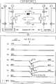
우선, 본 발명의 일실시 형태에 따른 온도 조정 장치(1)의 일례에 대해, 도 1을 참조하면서 설명한다. 본 실시 형태에서는, 온도 조정 장치(1)에 의해 기판 처리 장치(100)의 온도 제어가 실행된다.First, an example of the temperature adjusting
도 1에 나타낸 기판 처리 장치(100)는, 기판을 처리하는 장치의 일례이며, 예를 들어 알루미늄 또는 스테인리스강 등의 금속제의 원통형의 처리 용기(110)(챔버)를 가지고 있다. 처리 용기(110)는 접지되어 있다. 처리 용기(110) 내에는, 반도체 웨이퍼(W)(이하, 웨이퍼(W)라 한다)를 탑재하는 탑재대(111)가 마련되어 있다. 탑재대(111)는, 예를 들어 알루미늄으로 이루어지고, 처리 용기(110)의 바닥으로부터 수직 윗쪽으로 연장하는 통 형상 지지부(116)에 지지되어 있다. 탑재대(111) 상의 상면에는 웨이퍼(W)를 정전 흡착력으로 지지하기 위한 정전 척(112)이 마련되어 있다. 정전 척(112)은, 직류 전압이 인가됨으로써 쿨롱력으로 웨이퍼(W)를 척 상에 흡착 지지한다. 정전 척(112) 상에는 웨이퍼(W)가 탑재된다. 본 실시 형태에서는, 탑재대(111)의 내부에 탑재대 유로(170)가 형성되어 있다. 탑재대 유로(170)에 저온 브라인(brine) 또는 고온 브라인을 전환하여 흘림으로써, 탑재대(111)가 온도 제어된다. 이것에 의해 웨이퍼(W)를 소정의 온도로 제어할 수 있다.The
처리 용기(110)의 측벽과 통 형상 지지부(116)의 사이에는 배기로(120)가 형성되어 있다. 배기로(120)는, 도시하지 않는 배기 장치에 접속되고, 진공 펌프를 이용하여 처리 용기(110) 내의 처리 공간을 소정의 진공도까지 감압한다. 처리 용기(110)의 측벽에는, 웨이퍼(W)의 반입출구를 개폐하는 반송용의 게이트 밸브(130)가 부착되어 있다.An
탑재대(111)에는, 정합기(134)를 통해서 플라즈마 생성용의 고주파 전원(132)이 접속되어 있다. 고주파 전원(132)은, 예를 들어 60 MHz의 고주파 전력을 탑재대(111)에 인가한다. 이와 같이 하여 탑재대(111)는 하부 전극으로서 기능한다. 또, 처리 용기(110)의 천정부에는, 후술하는 샤워 헤드(138)가 접지 전위의 상부 전극으로서 마련되어 있다. 이것에 의해, 고주파 전원(132)으로부터의 고주파 전압은 탑재대(111)와 샤워 헤드(138)의 사이에 용량적으로 인가되고, 그 고주파의 방전에 의해, 정전 척(112)의 표면 근방에 고밀도의 플라즈마가 생성된다. 생성된 플라즈마의 작용에 의해, 처리 용기(110) 내에서는, 소정의 온도로 제어된 웨이퍼(W)에 에칭 처리 등의 플라즈마 처리가 실시된다.To the mount table 111, a high
천정부의 샤워 헤드(138)는, 다수의 가스 통기 구멍(136a)을 갖는 전극판(136)과, 전극판(136)을 착탈 가능하게 지지하는 전극 지지체(137)를 갖는다. 전극 지지체(137)의 내부에는 버퍼실(135)이 마련되고, 버퍼실(135)의 가스 도입구(135a)에는 가스 공급 배관(142)을 통해서 가스 공급원(140)이 연결되어 있다. 이것에 의해, 가스 공급원(140)으로부터 처리 용기(110) 내에 소망의 가스가 공급된다.The
(온도 조정 장치)(Temperature adjusting device)
본 실시 형태에 따른 온도 조정 장치(1)는, 저온 온도 조정 유닛(30) 및 고온 온도 조정 유닛(40)에 접속된다. 저온 온도 조정 유닛(30) 및 고온 온도 조정 유닛(40)은, 유체를 저장 가능한 대형의 탱크와 순환 펌프를 가지며, 각 탱크에 저장되는 유체의 양은, 항상 온도의 안정성을 담보할 수 있는 소정량을 채울 수 있다.The
저온 온도 조정 유닛(30)은, 저온 온도 조정 유닛(30)에 마련된 열 교환부(M1)에 의해 제 1 온도로 제어한 제 1 온도 조정 매체(이하, 「저온 브라인」이라 한다.)를 저온 탱크에 저장한다. 열 교환부(M1)는, 히터(31), 열 교환기(H/E)(증발기(32)), 열 교환기(H/E)(응축기(33)), 팽창 밸브(34) 및 압축기(35)를 갖는다. 저온 온도 조정 유닛(30)은, 제 1 온도 조정 매체의 온도를 제 1 온도로 제어하는 제 1 온도 제어부의 일례이다.The low temperature
고온 온도 조정 유닛(40)은, 고온 온도 조정 유닛(40)에 마련된 열 교환부(M2)에 의해 제 1 온도보다 높은 제 2 온도로 제어한 제 2 온도 조정 매체(이하, 「고온 브라인」이라 한다.)를 고온 탱크에 저장한다. 열 교환부(M2)는, 히터(41) 및 열 교환기(H/E)(42)를 갖는다. 고온 온도 조정 유닛(40)은, 제 2 온도 조정 매체의 온도를 제 1 온도보다 높은 제 2 온도로 제어하는 제 2 온도 제어부의 일례이다. 제 1 온도는 -30℃ 이상으로 제어되고, 제 2 온도는 70℃ 이하로 제어된다. 본 실시 형태에서는, 제 1 온도는 10℃, 제 2 온도는 70℃로 제어된다. 또, 본 실시 형태에서는, 저온 브라인 및 고온 브라인에 불소계 불활성 액체를 사용하지만 다른 액체를 사용해도 좋다.The high temperature
저온 온도 조정 유닛(30)으로부터 출력된 저온 브라인은 유로(R3)를 흐르고, 고온 온도 조정 유닛(40)으로부터 출력된 고온 브라인은 유로(R4)를 흐른다. 유로(R3), 유로(R4) 및 입구 유로(171)가 교차하는 점에는 3 방향 밸브(21)가 마련되어 있다. 3 방향 밸브(21)는, 유로(R3)를 흐르는 저온 브라인과 유로(R4)를 흐르는 고온 브라인을 전환하여 입구 유로(171)로 흘린다.The low temperature brine outputted from the low
탑재대(111)의 내부에는 탑재대 유로(170)가 형성되어 있다. 탑재대 유로(170)에는, 3 방향 밸브(21)에 의한 전환의 타이밍에 따라서 저온 브라인 또는 고온 브라인이 입구 유로(171)로부터 유입되고, 출구 유로(172)로 유출된다. 이와 같이 하여, 3 방향 밸브(21)에 의해 탑재대 유로(170)로 저온 브라인 또는 고온 브라인이 전환하여 흐르게 된다. 이것에 의해, 탑재대 유로(170)가 냉각 모드 및 가열 모드 중 어는 것으로 동작한다. 본 실시 형태에서는, 탑재대 유로(170)는 탑재대(111)의 내부에 형성된 유로이지만, 이것에 한정되지 않는다. 예를 들면, 탑재대 유로(170)는 정전 척(112)의 내부에 형성된 유로이어도 좋다.A mounting
탑재대 유로(170)는, 저온 브라인 및 고온 브라인을 순환시키는 순환 경로에 마련된다. 순환 경로에는, 히트 펌프 구조(10)와 전환 유닛(20)이 마련된다. 순환 경로는, 저온 온도 조정 유닛(30), 고온 온도 조정 유닛(40)→유로(R3), R4→(3 방향 밸브(21))→입구 유로(171)→탑재대 유로(170)→출구 유로(172)→(3 방향 밸브(22))→유로(R1, R2)→히트 펌프 구조(10)→저온 온도 조정 유닛(30), 고온 온도 조정 유닛(40)으로 나타낸다.The on-
출구 유로(172)로 유출한 저온 브라인 및 고온 브라인은, 3 방향 밸브(22)에 의해 전환되고, 유로(R1) 또는 유로(R2)를 거쳐서 저온 온도 조정 유닛(30) 또는 고온 온도 조정 유닛(40)으로 되돌아온다. 또, 3 방향 밸브(21, 22) 및 유로(R1~R4)의 일부를 형성하는 배관은 전환 유닛을 구성한다. 이와 같이 하여 온도 조정 장치(1)는, 고온 브라인 및 저온 브라인을 전환하여 순환시킴으로써 탑재대(111) 및 웨이퍼(W)의 온도를 조정할 수 있다.The low temperature brine and the high temperature brine discharged to the
그렇지만, 3 방향 밸브(22)에 의한 전환시에 고온 브라인이 저온 온도 조정 유닛(30) 측의 유로(R1)로 흐르는 경우가 있다. 또, 온도의 전환시에 저온 브라인이 고온 온도 조정 유닛(40) 측의 유로(R2)로 흐르는 경우가 있다. 이 경우, 고온 브라인이 저온 온도 조정 유닛(30)으로 돌아오거나 저온 브라인이 고온 온도 조정 유닛(40)으로 돌아오거나 하는 것으로 인한 열 부하로부터, 저온 온도 조정 유닛(30) 및 고온 온도 조정 유닛(40)의 내부의 브라인의 온도가 크게 변동하는 경우가 있다. 이것에 의해, 각 온도 조정 유닛의 브라인의 온도를 제어 온도로 하기까지 장시간이 걸려 생산성이 악화되거나, 각 온도 조정 유닛의 브라인의 온도가 제어 온도에 이르지 못한다고 하는 과제가 생긴다.However, when switching by the three-
그래서, 본 실시 형태에 따른 온도 조정 장치(1)는 히트 펌프 구조(10)를 갖는다. 히트 펌프 구조(10)는, 저온 브라인이 저온 온도 조정 유닛(30)으로 돌아오는 유로(R1) 및 고온 브라인이 고온 온도 조정 유닛(40)으로 돌아오는 유로(R2)에 접속되고, 저온 브라인과 고온 브라인의 사이에 있어서의 열의 교환을 행한다.Thus, the
상세하게는, 히트 펌프 구조(10)는, 유로(R1)에 증발기(12)를 가지고, 유로(R2)에 응축기(13)를 가진다. 또, 히트 펌프 구조(10)는, 증발기(12), 응축기(13), 팽창 밸브(14) 및 압축기(15) 및 이들을 연결하는 배관을 갖는다.More specifically, the
증발기(12)는, 외부로부터 열을 흡수하여 프레온을 증발시키는 기능을 갖는 열 교환기이다. 응축기(13)는, 기체의 프레온을 액화시켜서 열을 외부로 방출하는 기능을 갖는 열 교환기이다. 팽창 밸브(14)는, 프레온을 급격히 팽창시킴으로써, 프레온을 저온 및 저압으로 되도록 기능한다. 압축기(15)는, 프레온을 압축하고, 프레온을 고온 및 고압으로 되도록 기능한다.The
이와 같이 하여, 유로(R1)를 흐르는 프레온은, 증발기(12)에서 열이 흡수되고, 증발하여 기체로 되어 압축기(15)로 흡입되고, 고온 및 고압의 가스에 압축되어 응축기(13)에 보내진다. 그 프레온은, 응축기(13)에 있어서 열을 방출하여 액체로 되어 팽창 밸브(14)로 감압되어 증발기(12)로 되돌아온다.In this way, the Freon flowing through the flow path R1 absorbs heat in the
히트 펌프 구조(10)를 사용하지 않는 경우, 저온 브라인의 온도 제어를 부드럽게 행하기 위해서는 저온 온도 조정 유닛(30)의 압축기(35)로부터 출력 가능한 최대 전력량을 크게 할 필요가 있다. 또, 고온 브라인의 온도 제어를 부드럽게 행하기 위해서는 고온 온도 조정 유닛(40)의 히터(41)의 용량을 크게 할 필요가 있다. 이 경우, 압축기(35)에서 흡수되는 열은, 냉각수로 방출되고, 이용되지 않는다. 또, 압축기(35)의 최대 전력량 및 히터(41)의 용량을 크게 하면 전력 비용의 상승으로 이어진다.In the case where the
이것에 대해서, 본 실시 형태에 따른 온도 조정 장치(1)는, 돌아오는 유로(R1, R2)에 히트 펌프 구조(10)를 사용하는 것으로, 증발기(12)에서 흡수한 열을 응축기(13)로 방출함으로써, 저온 브라인과 고온 브라인의 열의 교환을 행할 수 있다.On the other hand, in the
또, 히트 펌프 구조(10)는 콘트롤러(11)를 갖는다. 콘트롤러(11)는, 유로(R1)에 마련한 온도 센서(S1, S2) 및 유로(R2)에 마련한 온도 센서(S4, S5)로부터 각각 온도(T1, T2, T4, T5)를 취득한다. 또, 콘트롤러(11)는, 유로(R3)에 부착된 온도 센서(S3)로부터 온도(T3)를 취득하고, 유로(R4)에 부착된 온도 센서(S6)로부터 온도(T6)를 취득한다.In addition, the
콘트롤러(11)는 온도 제어부(11a)를 갖는다. 온도 제어부(11a)는, 프로세서 등으로부터 구성되고, 히트 펌프 구조(10)의 각 부를 제어한다. 구체적으로는, 온도 제어부(11a)는, 저온 브라인의 온도가 10℃로 유지되도록 압축기(15) 및 팽창 밸브(14)의 조절을 행한다. 또, 온도 제어부(11a)는, 고온 브라인의 온도가 70℃로 유지되도록 압축기(15) 및 팽창 밸브(14)의 조절을 행한다. 이 결과, 소비 전력을 억제하고, 또한 부드럽게 저온 브라인 및 고온 브라인의 온도를 제어할 수 있어, 생산성의 향상을 도모할 수 있다.The
이와 같이, 본 실시 형태에 따른 온도 조정 장치(1)는, 돌아오는 유로(R1, R2)에 히트 펌프 구조(10)를 사용함으로써, 증발기(12)에서 흡수한 열을 응축기(13)로 방출한다. 이것에 의해, 유로(R1)를 흐르는 저온 브라인으로부터 유로(R2)를 흐르는 고온 브라인으로 효율적으로 열의 교환을 행할 수 있다. 이것에 의해, 압축기(15)로 사용되는 소비 전력의 3~7배의 저온 브라인 및 고온 브라인 간의 열의 교환이 가능하게 된다.As described above, the
예를 들면, 히트 펌프 구조(10)에 있어서 증발 행정→압축 행정→응축 행정→팽창 행정이 행해진다. 이때, 증발 행정에서 작동 매체인 브라인에 흡수되는 열량을 Q1, 응축 행정에서 브라인으로부터 방출되는 열량을 Q2, 압축기로부터의 입력 에너지를 W로 하면, 다음식(1)의 관계가 성립된다.For example, in the
Q2=Q1+W…(1)Q2 = Q1 + W ... (One)
여기서, 다음식(2)에서 구해지는 값을 성적 계수(COP : Coefficient Of Performance)로 정의한다. 히트 펌프 구조(10)의 COP의 값은 항상 1보다 큰 값으로 된다.Here, the value obtained from the following equation (2) is defined as a coefficient of performance (COP). The value of the COP of the
COP=Q2/W=Q2/(Q2-Q1)=T2/(T2-T1)…(2)COP = Q2 / W = Q2 / (Q2-Q1) = T2 / (T2-T1) (2)
여기서, T1는 저온 브라인의 온도, T2는 고온 브라인의 온도이다.Here, T1 is the temperature of the low temperature brine and T2 is the temperature of the high temperature brine.
식(2)으로부터 저온 브라인과 고온 브라인의 온도차가 작을수록, COP가 좋은 것을 알 수 있다. 또, 일 W는 열량으로 전환되는 것은 아니라, 열을 옮기기 위해서 이용되기 때문에, COP는 반드시 1보다 크게 되어, 3~7 정도이지만, 10 이상으로 하는 것도 가능하다. 이상으로부터, 본 실시 형태에 따르면, 압축기(15)에서 사용되는 소비 전력의 3~7배의 저온 브라인 및 고온 브라인 간의 열의 교환이 가능하게 된다.From the equation (2), the smaller the temperature difference between the low temperature brine and the high temperature brine, the better the COP. In addition, since the work W is not converted into heat but is used for transferring heat, the COP must be greater than 1 and is about 3 to 7, but it may be 10 or more. As described above, according to the present embodiment, it is possible to exchange heat between the low-temperature brine and the high-temperature brine which are three to seven times the power consumption used in the
[히트 펌프 구조의 동작과의 브라인 온도][Brine temperature of operation of heat pump structure]
다음으로, 히트 펌프 구조(10)의 구체적 동작과 브라인 온도의 일례에 대해서, 도 2~도 9를 참조하면서 설명한다. 전제로서, 탑재대(111)의 온도가 10℃로 안정되어 있을 때, 도 1의 유로(R3), 입구 유로(171), 탑재대 유로(170), 출구 유로(172) 및 유로(R3)의 순환 유로에는, 저온 온도 조정 유닛(30)을 거쳐서 저온 브라인이 흐른다. 3 방향 밸브(21, 22)에 의해 유로(R4) 및 유로(R2)에는 고온 브라인이 존재하는 폐회로로 되어 있다.Next, a concrete operation of the
탑재대(111)의 온도를 10℃에서 70℃로 전환할 때, 전환 유닛(20)의 3 방향 밸브(21, 22)의 개폐를 제어한다. 본 제어에 의해, 유로(R4), 입구 유로(171), 탑재대 유로(170), 출구 유로(172) 및 유로(R2)의 순환 유로에는, 고온 온도 조정 유닛(40)을 거쳐서 고온 브라인이 흐른다. 이때, 유로(R3) 및 유로(R1)에는 저온 브라인이 존재하는 폐회로로 되어 있다.When the temperature of the mounting table 111 is switched from 10 캜 to 70 캜, the opening and closing of the three-
더욱이, 탑재대(111)의 온도를 70℃에서 10℃로 전환할 때, 전환 유닛(20)의 3 방향 밸브(21, 22)의 개폐를 제어한다. 본 제어에 의해, 다시, 유로(R3), 입구 유로(171), 탑재대 유로(170), 출구 유로(172) 및 유로(R3)의 순환 유로에는, 저온 온도 조정 유닛(30)을 거쳐서 저온 브라인이 흐른다. 이때, 유로(R4) 및 유로(R2)에는 고온 브라인이 존재하는 폐회로로 되어 있다.Furthermore, when the temperature of the mounting table 111 is switched from 70 占 폚 to 10 占 폚, the opening and closing of the three-
(히트 펌프 미사용시의 브라인 온도)(Brine temperature when heat pump is not used)
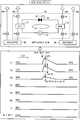
우선, 본 실시 형태에 따른 히트 펌프 구조(10)를 사용하고 있지 않는 경우의 저온 브라인 및 고온 브라인의 온도에 대해 설명한다. 도 2는 본 실시 형태에 따른 히트 펌프 구조(10)를 사용하지 않는 경우의 온도 센서의 검출치의 일례를 나타낸다. 온도 센서(S3)는 저온 온도 조정 유닛(30)으로부터 출력되고, 나가는 유로(R3)를 흐르는 저온 브라인의 온도(T3)를 검출한다. 저온 온도 조정 유닛(30)은 저온 브라인을 10℃로 제어하고 있다. 온도 센서(S2)는, 저온 온도 조정 유닛(30)으로의 돌아오는 유로(R1)를 흐르는 저온 브라인의 온도(T2)를 검출한다.First, the temperatures of the low temperature brine and the high temperature brine when the
온도 센서(S6)는, 고온 온도 조정 유닛(40)으로부터 출력되고, 나가는 유로(R4)를 흐르는 고온 브라인의 온도(T6)를 검출한다. 고온 온도 조정 유닛(40)은 고온 브라인을 70℃로 제어하고 있다. 온도 센서(S5)는, 고온 온도 조정 유닛(40)으로의 돌아오는 유로(R2)를 흐르는 고온 브라인의 온도(T5)를 검출한다.The temperature sensor S6 detects the temperature T6 of the high temperature brine flowing through the outflow channel R4 outputted from the high temperature
히트 펌프 미사용시, 도 2의 아래에 나타내는 바와 같이, 시간의 변화에 관계없이, 온도(T3)는, 저온 브라인의 온도가 저온 온도 조정 유닛(30)이 제어하는 10℃을 유지하고 있는 것을 나타내고, 온도(T6)는, 고온 브라인의 온도가 고온 온도 조정 유닛(40)이 제어하는 70℃을 유지하고 있는 것을 나타낸다.2, the temperature T3 indicates that the temperature of the low temperature brine is maintained at 10 deg. C controlled by the low temperature
한편, 탑재대 유로(170)를 흐른 후, 저온 온도 조정 유닛(30)으로의 돌아오는 유로(R1)를 흐르는 저온 브라인의 온도(T2)는 12℃를 나타낸다. 이것은, 고온 브라인의 일부가 저온 온도 조정 유닛(30)으로의 돌아오는 유로(R1)로 흘러들어감으로써 저온 온도 조정 유닛(30)으로 돌아오는 저온 브라인의 온도가 제어 온도보다 2℃ 상승한 것을 나타낸다.On the other hand, the temperature T2 of the low temperature brine flowing through the flow path R1 returning to the low temperature
마찬가지로, 탑재대 유로(170)를 흐른 후, 고온 온도 조정 유닛(40)으로의 돌아오는 유로(R2)를 흐르는 고온 브라인의 온도(T5)는 68℃을 나타낸다. 이것은, 저온 브라인의 일부가 고온 온도 조정 유닛(40)으로의 돌아오는 유로(R2)에 흘러들어옴으로써 고온 온도 조정 유닛(40)으로 되돌아오는 고온 브라인의 온도가 제어 온도보다 2℃ 저하한 것을 나타낸다.Likewise, the temperature T5 of the high temperature brine flowing through the flow path R2 returning to the high temperature
(히트 펌프 사용시의 브라인 온도)(Brine temperature when using heat pump)
다음으로, 본 실시 형태에 따른 히트 펌프 구조(10)를 사용하고 있는 경우의 저온 브라인 및 고온 브라인의 온도에 대해 설명한다. 도 3은 본 실시 형태에 따른 히트 펌프 구조(10)를 사용한 경우의 온도 센서의 검출치의 일례를 나타낸다. 히트 펌프 구조(10)를 온(가동)할 때까지, 온도 센서(S2, S3, S5, S6)의 온도는 도 2에 나타내는 온도를 유지한다. 또, 돌아오는 유로(R1)의 증발기(12)의 전후에 마련된 온도 센서(S1, S2)가 검출하는 온도(T1, T2)는, 히트 펌프 구조(10)를 온(가동)할 때까지 동일한 온도이다. 마찬가지로, 돌아오는 유로(R2)의 응축기(13)의 전후에 마련된 온도 센서(S4, S5)가 검출하는 온도(T4, T5)는, 히트 펌프 구조(10)를 온할 때까지 동일한 온도이다.Next, the temperatures of the low-temperature brine and the high-temperature brine when the
히트 펌프 구조(10)를 온하면, 압축기(15)가 온(가동)되고, 제 1 밸브(팽창 밸브(14))가 열린다. 이때, 유로(R1)를 흐르는 저온 브라인은, 증발기(12)에서 열을 흡수하고, 증발하여 기체로 되어 압축기(15)로 흡입되어, 고온 및 고압의 가스에 압축되어 응축기(13)에 보내진다. 저온 브라인은, 응축기(13)에 있어서 열을 방출하여 액체로 되어 팽창 밸브(14)에서 감압되어 증발기(12)로 돌아온다.When the
이것에 의해, 증발기(12)에서 열이 흡수된 저온 브라인의 온도는, 온도 센서(S2)의 검출치가 나타내는 바와 같이, 10℃으로 저하한다. 이것에 의해, 10℃의 저온 브라인이 저온 온도 조정 유닛(30)으로 돌아온다. 이 때문에, 저온 온도 조정 유닛(30)에 있어서의 저온 브라인의 온도 제어를 부드럽게 행할 수 있다.As a result, the temperature of the low-temperature brine in which heat is absorbed by the
증발기(12)에서 기체로 된 저온 브라인은, 압축기(15)에서 고온 및 고압의 가스로 압축되어 응축기(13)에서 열을 방출하여 액체로 된다. 방출한 열은, 돌아오는 유로(R2)를 흐르는 고온 브라인의 온도를 상승시킨다. 이것에 의해, 유로(R2)를 흐르는 고온 브라인의 온도(T5)는, 온도 센서(S5)의 검출치가 나타내는 바와 같이, 70℃으로 상승한다. 이것에 의해, 70℃의 고온 브라인이 고온 온도 조정 유닛(40)으로 돌아온다. 이 때문에, 고온 온도 조정 유닛(40)에 있어서의 고온 브라인의 온도 제어를 부드럽게 행할 수 있다.The low-temperature brine made of gas in the
(전환시(저온→고온)의 브라인 온도)(Brine temperature at the time of switching (low temperature? High temperature)
다음으로, 탑재대(111)의 온도를 저온에서 고온으로 전환할 때의 저온 브라인 및 고온 브라인의 온도에 대해, 본 실시 형태에 따른 히트 펌프 구조(10)를 오프하고 있는 경우와 온하고 있는 경우를 비교하여 설명한다. 도 4는 본 실시 형태에 따른 히트 펌프 구조(10)를 오프하고 있을 때의 전환시(저온→고온)의 온도의 일례를 나타낸다. 도 5는 본 실시 형태에 따른 히트 펌프 구조(10)를 온하고 있을 때의 전환시(저온→고온)의 온도의 일례를 나타낸다.Next, with respect to the temperature of the low temperature brine and the high temperature brine when the temperature of the mounting table 111 is switched from a low temperature to a high temperature, when the
우선, 도 4를 참조하면, 전환 유닛(20)의 3 방향 밸브(21, 22)를 전환하여 입구 유로(171)를 흐르는 브라인을 10℃의 저온 브라인에서 70℃의 고온 브라인으로 전환했을 때, 고온 브라인이 흐르는 유로(R2, R4)에 저온 브라인의 일부가 유입된다. 히트 펌프 구조(10)가 오프인 경우, 유로(R2)를 흐르는 고온 브라인의 온도(T4, T5)는, 하락폭 ΔT4, ΔT5만큼 저하한 후 서서히 원래의 온도 68℃로 돌아온다. 또, 유로(R4)를 흐르는 고온 브라인의 온도(T6)는, 하락폭 ΔT6만큼 저하한 후 서서히 원래의 온도 70℃로 돌아온다. 이때, 고온 온도 조정 유닛(40)은 고온 브라인을 70℃로 유지하려고 한다. 이 온도 제어의 효과에 의해 고온 온도 조정 유닛(40)으로부터 출력되고, 유로(R4)를 흐르는 고온 브라인의 온도(T6)의 전환시의 하락폭 ΔT6는, 유로(R2)를 흐르는 고온 브라인의 온도(T4, T5)의 전환시의 하락폭 ΔT4, ΔT5보다 작아진다. 즉, ΔT6<ΔT4, ΔT6<ΔT5로 된다. 또, 10℃의 저온 브라인에서 70℃의 고온 브라인으로의 전환시에는 유로(R1, R3)에 흐르는 저온 브라인의 온도(T1~T3)에 변동은 없다.4, when the three-
다음으로, 도 5에 나타내는 바와 같이, 전환시(저온→고온)에 히트 펌프 구조(10)가 온인 경우의 저온 브라인 및 고온 브라인의 온도에 대해 설명한다. 전환시, 고온 브라인이 흐르는 유로(R2, R4)에 저온 브라인의 일부가 유입된다.Next, as shown in Fig. 5, the temperatures of the low temperature brine and the high temperature brine when the
그렇지만, 도 5에서는, 히트 펌프 구조(10)가 온하고 있기 때문에, 히트 펌프 구조(10)의 열 교환기(13)에 의해 열을 교환한 후의 유로(R2)를 흐르는 고온 브라인의 온도(T5)의 하락폭 ΔT5는, 유로(R2)를 흐르는 고온 브라인의 온도(T4)의 하락폭 ΔT4보다 작아져서, 서서히 원래의 온도로 돌아온다. 즉, 히트 펌프 구조(10)가 온하면, 압축기(C)가 온되어, 팽창 밸브(14)(이하, 「제 1 밸브(14)」라고 한다.) 및 팽창 밸브(16)(이하, 「 제 2 밸브(16)」라 한다.)가 열린다. 유로(R1)를 흐르는 저온 브라인의 열은, 증발기(12)에서 흡수되고, 증발하여 기체로 되어 압축기(15)에 흡입되고, 고온 및 고압의 가스로 압축되어 응축기(13)로 보내진다. 고온 및 고압의 가스는, 응축기(13)에 있어서 열을 방출하여 액체로 되고 제 1 밸브(14) 및 제 2 밸브(16)에서 감압되어 일부는 증발기(12)로 돌아오고, 일부는 압축기(15)로 돌아온다.5, since the
이것에 의해, 도 4의 히트 펌프 구조(10)가 오프인 경우보다 온도(T5)의 하락폭 ΔT5가 작아진다. 이것에 의해, 고온 온도 조정 유닛(40)에 걸리는 열 부하가 작아지고, 고온 온도 조정 유닛(40)이 출력하는 고온 브라인의 온도(T6)는 70℃로 유지된다. 이상으로부터, 본 실시 형태에 따른 히트 펌프 구조(10)를 갖는 온도 조정 장치(1)에 따르면, 고온 브라인과 저온 브라인의 열의 교환에 의해 고온 브라인이 가열됨으로써, 고온 온도 조정 유닛(40)으로 돌아오는 브라인으로 인한 열 부하를 경감할 수 있다.Thus, the decrease? T5 of the temperature T5 is smaller than when the
(전환시(고온→저온)의 브라인 온도)(Brine temperature at the time of switching (high temperature? Low temperature)
다음으로, 탑재대(111)의 온도를 고온에서 저온으로 전환할 때의 저온 브라인 및 고온 브라인의 온도에 대해, 본 실시 형태에 따른 히트 펌프 구조(10)를 오프하고 있는 경우와 온하고 있는 경우를 비교하여 설명한다. 도 6은 본 실시 형태에 따른 히트 펌프 구조(10)를 오프하고 있을 때의 전환시(고온→저온)의 온도의 일례를 나타낸다. 도 7은 본 실시 형태에 따른 히트 펌프 구조(10)를 온하고 있을 때의 전환시(고온→저온)의 온도의 일례를 나타낸다.Next, with respect to the temperatures of the low temperature brine and the high temperature brine when the temperature of the mounting table 111 is switched from a high temperature to a low temperature, when the
우선, 도 6을 참조하면, 전환 유닛(20)의 3 방향 밸브(21, 22)를 전환하여 입구 유로(171)를 흐르는 브라인을 70℃의 고온 브라인에서 10℃의 저온 브라인으로 전환했을 때, 저온 브라인이 흐르는 유로(R1, R3)에 고온 브라인의 일부가 유입된다. 히트 펌프 구조(10)가 오프인 경우, 유로(R1)를 흐르는 고온 브라인의 온도(T1, T2)는, 상승폭 ΔT1, ΔT2만큼 상승한 후 서서히 원래의 온도 12℃로 돌아온다. 또, 유로(R3)를 흐르는 저온 브라인의 온도(T3)는, 상승폭 ΔT3만큼 상승한 후 서서히 원래의 온도 10℃으로 돌아온다. 이때, 저온 온도 조정 유닛(30)은 저온 브라인을 10℃로 유지하려고 한다. 이 온도 제어의 효과에 의해 저온 온도 조정 유닛(30)으로부터 출력되고, 유로(R3)를 흐르는 저온 브라인의 온도(T3)의 전환시의 상승폭 ΔT3는, 유로(R1)를 흐르는 저온 브라인의 온도(T1, T2)의 전환시의 상승폭 ΔT1, ΔT2보다 작아진다. 즉, ΔT3<ΔT1, ΔT3<ΔT2로 된다. 또, 70℃의 고온 브라인으로부터 10℃의 저온 브라인으로의 전환시에는 유로(R2, R4)에 흐르는 저온 브라인의 온도(T4~T6)에 변동은 없다.6, when the three-
다음으로, 도 7에 나타내는 바와 같이, 전환시(고온→저온)에 히트 펌프 구조(10)가 온인 경우의 저온 브라인 및 고온 브라인의 온도에 대해 설명한다. 전환시, 저온 브라인이 흐르는 유로(R1, R3)에 고온 브라인의 일부가 유입된다.Next, as shown in Fig. 7, the temperatures of the low temperature brine and the high temperature brine when the
그렇지만, 도 7에서는, 히트 펌프 구조(10)가 온하고 있기 때문에, 히트 펌프 구조(10)의 열 교환기(12)에 의해 열을 교환한 후의 유로(R1)를 흐르는 저온 브라인의 온도(T2)의 상승폭 ΔT2는, 온도 T1의 상승폭 ΔT2보다 작아져서, 서서히 원래의 온도로 돌아온다. 즉, 히트 펌프 구조(10)가 온하면, 압축기(C)가 온되어, 팽창 밸브인 제 1 밸브(14) 및 제 3 밸브(17)가 열린다. 유로(R1)를 흐르는 저온 브라인의 열은, 증발기(12)에서 흡수되고, 증발하여 기체로 되어 압축기(15)에 흡입되어, 고온 및 고압의 가스로 압축되어 응축기(13)에 보내진다. 고온 및 고압의 가스는, 응축기(13)에서 열을 방출하여 액체로 되어 제 1 밸브(14) 및 제 3 밸브(17)에서 감압되어 일부는 증발기(12)로 돌아오고, 일부는 응축기(13)에 흐른다.7, the temperature T2 of the low-temperature brine flowing through the flow path R1 after the heat exchange by the
이것에 의해, 도 6의 히트 펌프 구조(10)가 오프인 경우보다 온도(T2)의 상승폭 ΔT2가 작아진다. 이것에 의해, 저온 온도 조정 유닛(30)에 걸리는 열 부하가 작아져서, 저온 온도 조정 유닛(30)이 출력하는 저온 브라인의 온도(T3)는 10℃로 유지된다. 이상으로부터, 본 실시 형태에 따른 히트 펌프 구조(10)를 갖는 온도 조정 장치(1)에 따르면, 고온 브라인과 저온 브라인의 열의 교환에 의해 저온 브라인이 냉각됨으로써, 저온 온도 조정 유닛(30)으로 돌아오는 브라인으로 인한 열 부하를 경감할 수 있다.As a result, the rise? T2 of the temperature T2 is smaller than when the
[냉각수의 이용][Use of cooling water]
다음으로, 상기에 설명한 히트 펌프 구조(10)에 의해서도, 전환시(저온→고온)의 고온 브라인의 가열 능력, 및 전환시(고온→저온)의 저온 브라인의 냉각 능력이 부족한 경우가 있다. 이 경우, 히트 펌프 구조(10)와 냉각수(예를 들면 수도물)의 열 교환을 행함으로써, 저온 온도 조정 유닛(30) 및 고온 온도 조정 유닛(40)으로 돌아오는 브라인으로 인한 열 부하를 더 저감할 수 있다.Next, also with the
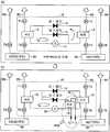
도 8(a)에 나타내는 히트 펌프 구조(10)에서는, 전환시(저온→고온)에 있어서, 고온 브라인과 저온 브라인의 열의 교환에 의해 고온 브라인이 가열된다. 이때, 고온 브라인의 가열이 부족하면, 도 5의 온도(T5)의 하락폭 ΔT5가 커져서, 고온 온도 조정 유닛(40)으로 돌아오는 브라인으로 인한 열 부하를 충분히 경감할 수 없는 상태로 된다.In the
이 경우, 도 8(b)에 나타내는 히트 펌프 구조(10)에서는, 제 2 밸브(16)에 직렬로 증발기(18)를 마련한다. 증발기(18)는, 증발기(12)에 병렬로 접속되고, 냉각수로부터 열을 흡수한다(흡열).In this case, in the
증발기(12, 18)에서 액체로부터 기체로 되어 압축기(15)에 흡입되고, 압축된 가스는, 응축기(13)로 보내져서 응축기(13)에서 열을 방출하여 액체로 되어 제 1 밸브(14) 및 제 2 밸브(16)에서 감압되어 증발기(12) 또는 증발기(18)로 보내진다.The liquid is sucked into the
이상으로 설명한 바와 같이, 일실시 형태에 따른 도 8(b)에 나타내는 히트 펌프 구조(10)에 따르면, 열 교환기(18)에 의해 냉각수로부터 열을 흡수함으로써 가열 능력을 높이고, 고온 온도 조정 유닛(40)으로 돌아오는 브라인으로 인한 열 부하를 더 저감할 수 있다.As described above, according to the
마찬가지로 하여, 도 9(a)에 나타내는 히트 펌프 구조(10)에서는, 전환시(고온→저온)에 있어서, 고온 브라인과 저온 브라인의 열의 교환에 의해 저온 브라인이 냉각된다. 이때, 저온 브라인의 냉각이 부족하면, 도 7의 온도(T2)의 상승폭 ΔT2가 커져서, 저온 온도 조정 유닛(30)으로 돌아오는 브라인으로 인한 열 부하를 충분히 경감할 수 없는 상태로 된다.Similarly, in the
이 경우, 도 9(b)에 나타내는 히트 펌프 구조(10)에서는, 제 3 밸브(17)에 직렬로 응축기(19)를 마련한다. 응축기(19)는, 응축기(13)에 병렬로 접속되어, 냉각수로 열을 방출한다(배열).In this case, in the
응축기(13, 19)에 보내진 고온 및 고압의 기체는, 응축기(13, 19)에서 열을 방출하여 기체로부터 액체로 되고, 제 1 밸브(14) 및 제 3 밸브(17)에서 감압되어 증발기(12) 또는 응축기(19)에 보내진다.The high temperature and high pressure gases sent to the
이상으로 설명한 바와 같이, 일실시 형태에 따른 도 9(b)에 나타내는 히트 펌프 구조(10)에 따르면, 열 교환기(19)에 의해 냉각수로 열을 방출함으로써 냉각 능력을 높이고, 저온 온도 조정 유닛(30)으로 돌아오는 브라인으로 인한 열 부하를 더 저감할 수 있다.As described above, according to the
[변형예][Modifications]
마지막으로, 본 실시 형태의 변형예에 따른 온도 조정 장치(1)에 대해, 도 10을 참조하면서 설명한다. 도 10의 본 실시 형태의 변형예에 따른 온도 조정 장치(1)는, 도 1의 본 실시 형태에 따른 온도 조정 장치(1)와 비교하여, 2 계통의 순환 유로를 갖는다. 하나의 순환 경로는, 저온 온도 조정 유닛(30), 고온 온도 조정 유닛(40)→유로(R3a), R4a→(3 방향 밸브(21a))→입구 유로(171a)→주연부 탑재대 유로(170a)→출구 유로(172a)→(3 방향 밸브(22a))→유로(R1a, R2a)→히트 펌프 구조(10a)→저온 온도 조정 유닛(30), 고온 온도 조정 유닛(40)으로 나타낸다.Finally, a
다른 순환 경로는, 저온 온도 조정 유닛(30), 고온 온도 조정 유닛(40)→유로(R3b, R4b)→(3 방향 밸브(21b))→입구 유로(171b)→중앙부 탑재대 유로(170b)→출구 유로(172b)→(3 방향 밸브(22b))→유로(R1b, R2b)→히트 펌프 구조(10b)→저온 온도 조정 유닛(30), 고온 온도 조정 유닛(40)으로 나타낸다.The other circulation paths are connected to the low temperature
히트 펌프 구조(10a)에 있어서, 배관을 흐르는 프레온은, 증발기(12a)에서 열을 흡수하고, 증발하여 기체로 되어 압축기(15a)로 흡입되고, 고온 및 고압의 가스로 압축되어 응축기(13a)로 보내진다. 그 브라인은, 응축기(13a)에서 열을 방출하여 액체로 되어 팽창 밸브(14a)에서 감압되어 증발기(12a)로 돌아온다.In the
마찬가지로, 히트 펌프 구조(10b)에 있어서, 배관을 흐르는 프레온은, 증발기(12b)에서 열을 흡수하고, 증발하여 기체로 되어 압축기(15b)에 흡입되고, 고온 및 고압의 가스로 압축되어 응축기(13b)에 보내진다. 그 브라인은, 응축기(13b)에서 열을 방출하여 액체로 되어 팽창 밸브(14b)에서 감압되어 증발기(12b)로 돌아온다.Likewise, in the
이와 같이, 변형예에 따른 온도 조정 장치(1)에서는, 복수의 순환 경로를, 탑재대(111)의 내부에 분리되어 복수 마련된 탑재대 유로(170)에 각각 접속한다. 이것에 의해, 변형예에 따른 온도 조정 장치(1)에서는, 탑재대(111)의 주연부와 중앙부를 각각 다른 온도로 제어할 수 있다. 이것에 의해, 웨이퍼(W)의 처리시의 온도 제어성을 높일 수 있다. 또, 변형예에 따른 온도 조정 장치(1)에서는, 2개의 히트 펌프 구조(10a, 10b)가 마련된다. 이것에 의해, 저온 온도 조정 유닛(30) 및 고온 온도 조정 유닛(40)으로 돌아오는 브라인으로 인한 열 부하를 더 경감할 수 있다.As described above, in the
또, 본 변형예에 따른 온도 조정 장치(1)에서는, 2 개의 순환 경로를 나타냈지만, 순환 경로의 수는, 이것에 한정하지 않고, 3 이상이어도 좋다. 또, 이상에서 설명한 유로(R1, R1a, R1b)는 제 1 유로의 일례이다. 유로(R2, R2a, R2b)는 제 2 유로의 일례이다.In the
이상, 본 실시 형태 및 변형예에 따른 온도 조정 장치(1)에 따르면, 다른 2 이상의 온도 조정 유닛으로 돌아오는 브라인으로 인한 열 부하를 경감할 수 있다. 즉, 본 실시 형태 및 변형예에 따른 온도 조정 장치(1)에 따르면, 전환시에 칠러로 돌아오는 고온 브라인과 저온 브라인의 열의 교환을 행하는 히트 펌프 구조를 마련함으로써, 저온 온도 조정 유닛(30) 및 고온 온도 조정 유닛(40)으로 돌아오는 브라인으로 인한 열 부하를 저감시킬 수 있다. 이 결과, 저온 온도 조정 유닛(30) 및 고온 온도 조정 유닛(40)으로 돌아오는 브라인으로 인한 열 부하에 있어서의 전력 비용이 비싸지는 것을 회피할 수 있다.As described above, according to the
또, 저온 브라인과 고온 브라인이 섞임으로써 생기는 히트 쇼크로 인해, 저온 온도 조정 유닛(30) 및 고온 온도 조정 유닛(40)의 내구성이 나빠지는 것을 회피할 수 있다.It is also possible to avoid the deterioration of the durability of the low
이상, 온도 조정 장치 및 기판 처리 장치를 상기 실시 형태에 따라 설명했지만, 본 발명에 따른 온도 조정 장치 및 기판 처리 장치는 상기 실시 형태로 한정되는 것이 아니고, 본 발명의 범위 내에서 여러 변형 및 개량이 가능하다. 상기 복수의 실시 형태에 기재된 사항은, 모순되지 않는 범위에서 조합할 수 있다.The temperature adjusting apparatus and the substrate processing apparatus according to the present invention are not limited to the above-described embodiments, and various modifications and improvements can be made within the scope of the present invention. It is possible. The matters described in the plural embodiments can be combined within a range that does not contradict each other.
예를 들면, 본 발명에 따른 온도 조정 장치 및 기판 처리 장치는, 도 1에 간략하게 나타낸 용량 결합형 플라즈마(CCP : Capacitively Coupled Plasma) 장치뿐만이 아니라, 그 외의 기판 처리 장치에 적용 가능하다. 그 외의 기판 처리 장치로서는, 유도 결합형 플라즈마(ICP : Inductively Coupled Plasma), 래디얼 라인 슬롯 안테나를 이용한 플라즈마 처리 장치, 헬리콘파 여기형 플라즈마(HWP : Helicon Wave Plasma) 장치, 전자 사이클론 공명 플라즈마(ECR : Electron Cyclotron Resonance Plasma) 장치 등이어도 좋다.For example, the temperature adjusting apparatus and the substrate processing apparatus according to the present invention can be applied not only to a capacitively coupled plasma (CCP) apparatus shown in FIG. 1 but also to other substrate processing apparatuses. Examples of other substrate processing apparatuses include an inductively coupled plasma (ICP), a plasma processing apparatus using a radial line slot antenna, a Helicon Wave Plasma (HWP) apparatus, an electron cyclotron resonance plasma (ECR) Electron Cyclotron Resonance Plasma) device.
본 명세서에서는, 에칭 대상으로서 웨이퍼(W)(반도체)에 대해 설명했지만, 피처리 기판은, 웨이퍼(W)에 한정하지 않고, LCD(Liquid Crystal Display), FPD(Flat Panel Display) 등에 이용되는 각종 기판이나, 포토마스크, CD 기판, 프린트 기판 등이어도 좋다.Although the wafer W (semiconductor) has been described in this specification as an object to be etched, the substrate to be processed is not limited to the wafer W, but may be various kinds of substrates used for LCD (Liquid Crystal Display), FPD A substrate, a photomask, a CD substrate, a printed substrate, or the like.
1 : 온도 조정 장치10 : 히트 펌프 구조
12 : 증발기(열 교환기) 13 : 응축기(열 교환기)
14 : 팽창 밸브(제 1 밸브) 15 : 압축기
16 : 팽창 밸브(제 2 밸브) 17 : 팽창 밸브(제 3 밸브)
18 : 증발기(열 교환기) 19 : 응축기(열 교환기)
20 : 전환 유닛 21, 22 : 3 방향 밸브
30 : 저온 온도 조정 유닛40 : 고온 온도 조정 유닛
100 : 기판 처리 장치110 : 처리 용기
111 : 탑재대 112 : 정전 척
170 : 탑재대 유로 171 : 입구 유로
172 : 출구 유로 S1~S6 : 온도 센서
R1~R4 : 유로1: Temperature controller 10: Heat pump structure
12: evaporator (heat exchanger) 13: condenser (heat exchanger)
14: expansion valve (first valve) 15: compressor
16: expansion valve (second valve) 17: expansion valve (third valve)
18: evaporator (heat exchanger) 19: condenser (heat exchanger)
20: switching
30: low temperature adjusting unit 40: high temperature adjusting unit
100: substrate processing apparatus 110: processing vessel
111: mounting table 112: electrostatic chuck
170: Mounting bar 171: Entrance channel
172: outlet flow path S1 to S6: temperature sensor
R1 to R4:
Claims (6)
Translated fromKorean제 1 온도 조정 매체의 온도를 제 1 온도로 제어하는 제 1 온도 제어부와,
제 2 온도 조정 매체의 온도를 제 1 온도보다 높은 제 2 온도로 제어하는 제 2 온도 제어부와,
상기 탑재대의 내부에 마련되고, 상기 제 1 온도 조정 매체와 상기 제 2 온도 조정 매체가 전환되어 흐르게 되는 탑재대 유로와,
상기 탑재대 유로로부터 유출한 상기 제 1 온도 조정 매체가 흐르는 제 1 유로와,
상기 탑재대 유로로부터 유출한 상기 제 2 온도 조정 매체가 흐르는 제 2 유로와,
상기 제 1 유로 및 상기 제 2 유로에 접속되고, 상기 제 1 온도 조정 매체와 상기 제 2 온도 조정 매체의 사이에 있어서의 열의 교환을 행하는 히트 펌프 구조
를 갖는 피처리 기판의 온도 조정 장치.
A mounting table on which a substrate to be processed is mounted,
A first temperature control unit for controlling the temperature of the first temperature adjusting medium to a first temperature,
A second temperature control unit for controlling the temperature of the second temperature adjusting medium to a second temperature higher than the first temperature,
A mounting table provided in the mounting table for allowing the first temperature adjusting medium and the second temperature adjusting medium to switch and flow,
A first flow path through which the first temperature adjusting medium flows out from the loading passage,
A second flow path through which the second temperature adjustment medium flows out from the loading passage,
A heat pump structure connected to the first flow path and the second flow path for exchanging heat between the first temperature adjustment medium and the second temperature adjustment medium
And the temperature of the target substrate.
상기 제 1 온도는 -30℃ 이상이며, 상기 제 2 온도는 70℃ 이하인 온도 조정 장치.
The method according to claim 1,
Wherein the first temperature is -30 占 폚 or higher and the second temperature is 70 占 폚 or lower.
상기 히트 펌프 구조는 상기 제 1 유로에 증발기를 가지며, 상기 제 2 유로에 응축기를 갖는 온도 조정 장치.
3. The method according to claim 1 or 2,
Wherein the heat pump structure has an evaporator in the first flow path, and a condenser in the second flow path.
상기 히트 펌프 구조는, 상기 제 1 유로 및 상기 제 2 유로의 각각에 마련된 온도 센서에 의해 얻어진 온도에 근거하여 온도 제어를 행하는 온도 제어부를 갖는 온도 조정 장치.
3. The method according to claim 1 or 2,
Wherein the heat pump structure has a temperature control section that performs temperature control based on a temperature obtained by a temperature sensor provided in each of the first flow path and the second flow path.
상기 제 1 온도 조정 매체가 흐르는 복수의 상기 제 1 유로와, 상기 제 2 온도 조정 매체가 흐르는 복수의 상기 제 2 유로와, 상기 제 1 온도 조정 매체와 상기 제 2 온도 조정 매체의 사이의 열의 교환을 행하는 복수의 상기 히트 펌프 구조를 가지며,
복수의 상기 제 1 유로, 복수의 상기 제 2 유로 및 복수의 상기 히트 펌프 구조는 복수의 계통의 유로를 구성하고, 상기 복수의 계통의 유로는, 상기 탑재대의 내부에 분리되어 복수 마련된 탑재대 유로에 접속되는
온도 조정 장치.
3. The method according to claim 1 or 2,
A plurality of first flow paths through which the first temperature regulating medium flows, a plurality of second flow paths through which the second temperature regulating medium flows, and a heat exchanger for exchanging heat between the first temperature regulating medium and the second temperature regulating medium Wherein said heat pump structure has a plurality of said heat pump structures,
Wherein the plurality of the first flow paths, the plurality of the second flow paths, and the plurality of the heat pump structures constitute a plurality of flow paths of the system, Connected to
Temperature control unit.
상기 처리 용기의 내부에 마련되고, 피처리 기판을 탑재하는 탑재대와,
제 1 온도 조정 매체의 온도를 제 1 온도로 제어하는 제 1 온도 제어부와,
제 2 온도 조정 매체의 온도를 제 1 온도보다 높은 제 2 온도로 제어하는 제 2 온도 제어부와,
상기 탑재대의 내부에 마련되고, 상기 제 1 온도 조정 매체와 상기 제 2 온도 조정 매체가 전환되어 흐르는 탑재대 유로와,
상기 탑재대 유로로부터 유출한 상기 제 1 온도 조정 매체가 흐르는 제 1 유로와,
상기 탑재대 유로로부터 유출한 상기 제 2 온도 조정 매체가 흐르는 제 2 유로와,
상기 제 1 온도 조정 매체와 상기 제 2 온도 조정 매체의 사이의 열의 교환을 행하는 히트 펌프 구조
를 갖는 기판 처리 장치.A processing container for processing the substrate to be processed,
A mounting table provided inside the processing vessel for mounting a substrate to be processed,
A first temperature control unit for controlling the temperature of the first temperature adjusting medium to a first temperature,
A second temperature control unit for controlling the temperature of the second temperature adjusting medium to a second temperature higher than the first temperature,
A mounting table provided in the mounting table for switching between the first temperature adjusting medium and the second temperature adjusting medium,
A first flow path through which the first temperature adjusting medium flows out from the loading passage,
A second flow path through which the second temperature adjustment medium flows out from the loading passage,
A heat pump structure for exchanging heat between the first temperature adjusting medium and the second temperature adjusting medium
.
Applications Claiming Priority (2)
| Application Number | Priority Date | Filing Date | Title |
|---|---|---|---|
| JPJP-P-2015-186728 | 2015-09-24 | ||
| JP2015186728AJP6570390B2 (en) | 2015-09-24 | 2015-09-24 | Temperature control apparatus and substrate processing apparatus |
Publications (2)
| Publication Number | Publication Date |
|---|---|
| KR20170036629Atrue KR20170036629A (en) | 2017-04-03 |
| KR102568025B1 KR102568025B1 (en) | 2023-08-17 |
Family
ID=58409844
Family Applications (1)
| Application Number | Title | Priority Date | Filing Date |
|---|---|---|---|
| KR1020160121208AActiveKR102568025B1 (en) | 2015-09-24 | 2016-09-22 | Temperature adjustment apparatus and substrate processing apparatus |
Country Status (4)
| Country | Link |
|---|---|
| US (1) | US10903057B2 (en) |
| JP (1) | JP6570390B2 (en) |
| KR (1) | KR102568025B1 (en) |
| TW (1) | TWI746460B (en) |
Cited By (4)
| Publication number | Priority date | Publication date | Assignee | Title |
|---|---|---|---|---|
| KR20200042393A (en)* | 2018-10-15 | 2020-04-23 | 도쿄엘렉트론가부시키가이샤 | Temperature controlling system and temperature controlling method |
| KR20210056257A (en)* | 2019-11-08 | 2021-05-18 | 시케이디 가부시키가이샤 | Temperature control system and integrated temperature control system |
| KR20210056256A (en)* | 2019-11-08 | 2021-05-18 | 시케이디 가부시키가이샤 | Temperature control system and integrated temperature control system |
| WO2025033803A1 (en)* | 2023-08-09 | 2025-02-13 | 피에스케이 주식회사 | Substrate processing device and substrate processing method |
Families Citing this family (27)
| Publication number | Priority date | Publication date | Assignee | Title |
|---|---|---|---|---|
| KR101681190B1 (en)* | 2015-05-15 | 2016-12-02 | 세메스 주식회사 | method and Apparatus for Processing Substrate |
| JP6554387B2 (en)* | 2015-10-26 | 2019-07-31 | 東京エレクトロン株式会社 | Substrate cooling method in load lock apparatus, substrate transfer method, and load lock apparatus |
| JP6990058B2 (en)* | 2017-07-24 | 2022-01-12 | 伸和コントロールズ株式会社 | Temperature control device |
| US20190137040A1 (en)* | 2017-11-08 | 2019-05-09 | Delta Design, Inc. | System and method for liquid nitrogen recycling |
| JP6971836B2 (en)* | 2017-12-26 | 2021-11-24 | キヤノン株式会社 | Cooling device, semiconductor manufacturing device and semiconductor manufacturing method |
| US10510564B2 (en)* | 2018-01-10 | 2019-12-17 | Lam Research Corporation | Dynamic coolant mixing manifold |
| JP6920245B2 (en)* | 2018-04-23 | 2021-08-18 | 東京エレクトロン株式会社 | Temperature control method |
| JP7128023B2 (en)* | 2018-05-01 | 2022-08-30 | 株式会社ニシヤマ | Temperature control system, manufacturing equipment and inspection equipment |
| US10900124B2 (en) | 2018-06-12 | 2021-01-26 | Lam Research Corporation | Substrate processing chamber with showerhead having cooled faceplate |
| KR102608957B1 (en)* | 2018-08-27 | 2023-12-01 | 삼성전자주식회사 | Plasma processing apparatus |
| US20220005675A1 (en)* | 2018-11-20 | 2022-01-06 | Lam Research Corporation | Dual-phase cooling in semiconductor manufacturing |
| JP7187303B2 (en)* | 2018-12-26 | 2022-12-12 | 東京エレクトロン株式会社 | temperature controller |
| JP2020120081A (en)* | 2019-01-28 | 2020-08-06 | 東京エレクトロン株式会社 | Substrate processing apparatus |
| JP6624623B1 (en)* | 2019-06-26 | 2019-12-25 | 伸和コントロールズ株式会社 | Temperature control device and temperature control device |
| KR20210061846A (en)* | 2019-11-20 | 2021-05-28 | 삼성전자주식회사 | Substrate processing apparatus and semiconductor device manufacturing method using the same |
| DE102020002962B4 (en)* | 2020-05-18 | 2025-03-13 | Att Advanced Temperature Test Systems Gmbh | Temperature control device, system and method for temperature control of a sample table for semiconductor wafers and/or hybrids |
| US12247520B2 (en)* | 2020-06-16 | 2025-03-11 | Ge Infrastructure Technology Llc | Wet dry integrated circulation cooling system |
| CN114256046B (en)* | 2020-09-22 | 2024-07-05 | 中微半导体设备(上海)股份有限公司 | Plasma processing apparatus and method of operating the same |
| CN112501589A (en)* | 2020-11-06 | 2021-03-16 | 北京印刷学院 | Atomic layer deposition device |
| KR102605999B1 (en)* | 2021-03-17 | 2023-11-23 | 세메스 주식회사 | Chemical liquid providing unit and substrate treating apparatus including the same |
| JP7555876B2 (en)* | 2021-05-24 | 2024-09-25 | 株式会社荏原製作所 | Sub-fab area installation equipment |
| JP7522073B2 (en)* | 2021-05-24 | 2024-07-24 | 株式会社荏原製作所 | Sub-fab area installation equipment |
| CN114582759A (en)* | 2022-03-02 | 2022-06-03 | 北京京仪自动化装备技术股份有限公司 | Temperature control equipment for integrated circuit manufacturing process and integrated circuit manufacturing process system |
| JP7728213B2 (en)* | 2022-03-18 | 2025-08-22 | キオクシア株式会社 | Plasma processing apparatus and plasma processing method |
| DE102022125538A1 (en)* | 2022-10-04 | 2024-04-04 | Dürr Systems Ag | System and method for generating heating and cooling services in a treatment system for workpieces |
| KR102685931B1 (en)* | 2023-03-02 | 2024-07-17 | 한종원 | Cold and hot conversion system |
| JP7547525B1 (en) | 2023-03-03 | 2024-09-09 | 株式会社荏原製作所 | Cooling system for semiconductor manufacturing process, and semiconductor manufacturing system |
Citations (8)
| Publication number | Priority date | Publication date | Assignee | Title |
|---|---|---|---|---|
| JPH05243191A (en) | 1992-02-26 | 1993-09-21 | Nec Corp | Dry etching device |
| JP2006261541A (en)* | 2005-03-18 | 2006-09-28 | Tokyo Electron Ltd | Substrate mounting board, substrate processor and method for processing substrate |
| JP2007116098A (en) | 2005-10-20 | 2007-05-10 | Applied Materials Inc | Capacitively coupled plasma reactor with cooled / heated wafer support with uniform temperature distribution |
| JP2009117443A (en) | 2007-11-02 | 2009-05-28 | Tokyo Electron Ltd | Temperature adjusting apparatus and temperature adjusting method for substrate to be processed, and plasma processing apparatus including the same |
| US8410393B2 (en) | 2010-05-24 | 2013-04-02 | Lam Research Corporation | Apparatus and method for temperature control of a semiconductor substrate support |
| KR101327114B1 (en)* | 2007-04-27 | 2013-11-07 | 시케이디 가부시키가이샤 | Temperature control device |
| KR20180051423A (en)* | 2016-11-08 | 2018-05-16 | 가부시키가이샤 나카야 | Method of controlling circulated liquid temperature using parameter control system chiller for each area by remote control and maintenance method |
| KR20190018327A (en)* | 2017-08-14 | 2019-02-22 | (주)피티씨 | Chiller apparatus for semiconductor process |
Family Cites Families (10)
| Publication number | Priority date | Publication date | Assignee | Title |
|---|---|---|---|---|
| US4173924A (en)* | 1978-03-01 | 1979-11-13 | Schweitzer Industrial Corporation | Paint spray booth with air supply system |
| JPH04275420A (en)* | 1991-03-04 | 1992-10-01 | Matsushita Electric Ind Co Ltd | Cooling equipment in dry etching equipment |
| JP2746025B2 (en)* | 1992-12-03 | 1998-04-28 | ダイキン工業株式会社 | Two-channel liquid cooling device |
| JP2002168551A (en)* | 2000-11-30 | 2002-06-14 | Tokyo Electron Ltd | Cooling device for electrode of treating device |
| JP5703038B2 (en)* | 2011-01-26 | 2015-04-15 | 株式会社日立ハイテクノロジーズ | Plasma processing equipment |
| US10274270B2 (en)* | 2011-10-27 | 2019-04-30 | Applied Materials, Inc. | Dual zone common catch heat exchanger/chiller |
| JP5912439B2 (en)* | 2011-11-15 | 2016-04-27 | 東京エレクトロン株式会社 | Temperature control system, semiconductor manufacturing apparatus, and temperature control method |
| CN202598947U (en) | 2012-02-02 | 2012-12-12 | 苟仲武 | Comprehensive heating and refrigeration energy-saving apparatus and system |
| JP6014513B2 (en)* | 2012-08-29 | 2016-10-25 | 東京エレクトロン株式会社 | Plasma etching apparatus and control method |
| US9916967B2 (en)* | 2013-03-13 | 2018-03-13 | Applied Materials, Inc. | Fast response fluid control system |
- 2015
- 2015-09-24JPJP2015186728Apatent/JP6570390B2/enactiveActive
- 2016
- 2016-09-16USUS15/267,246patent/US10903057B2/enactiveActive
- 2016-09-22TWTW105130542Apatent/TWI746460B/enactive
- 2016-09-22KRKR1020160121208Apatent/KR102568025B1/enactiveActive
Patent Citations (8)
| Publication number | Priority date | Publication date | Assignee | Title |
|---|---|---|---|---|
| JPH05243191A (en) | 1992-02-26 | 1993-09-21 | Nec Corp | Dry etching device |
| JP2006261541A (en)* | 2005-03-18 | 2006-09-28 | Tokyo Electron Ltd | Substrate mounting board, substrate processor and method for processing substrate |
| JP2007116098A (en) | 2005-10-20 | 2007-05-10 | Applied Materials Inc | Capacitively coupled plasma reactor with cooled / heated wafer support with uniform temperature distribution |
| KR101327114B1 (en)* | 2007-04-27 | 2013-11-07 | 시케이디 가부시키가이샤 | Temperature control device |
| JP2009117443A (en) | 2007-11-02 | 2009-05-28 | Tokyo Electron Ltd | Temperature adjusting apparatus and temperature adjusting method for substrate to be processed, and plasma processing apparatus including the same |
| US8410393B2 (en) | 2010-05-24 | 2013-04-02 | Lam Research Corporation | Apparatus and method for temperature control of a semiconductor substrate support |
| KR20180051423A (en)* | 2016-11-08 | 2018-05-16 | 가부시키가이샤 나카야 | Method of controlling circulated liquid temperature using parameter control system chiller for each area by remote control and maintenance method |
| KR20190018327A (en)* | 2017-08-14 | 2019-02-22 | (주)피티씨 | Chiller apparatus for semiconductor process |
Cited By (4)
| Publication number | Priority date | Publication date | Assignee | Title |
|---|---|---|---|---|
| KR20200042393A (en)* | 2018-10-15 | 2020-04-23 | 도쿄엘렉트론가부시키가이샤 | Temperature controlling system and temperature controlling method |
| KR20210056257A (en)* | 2019-11-08 | 2021-05-18 | 시케이디 가부시키가이샤 | Temperature control system and integrated temperature control system |
| KR20210056256A (en)* | 2019-11-08 | 2021-05-18 | 시케이디 가부시키가이샤 | Temperature control system and integrated temperature control system |
| WO2025033803A1 (en)* | 2023-08-09 | 2025-02-13 | 피에스케이 주식회사 | Substrate processing device and substrate processing method |
Also Published As
| Publication number | Publication date |
|---|---|
| TWI746460B (en) | 2021-11-21 |
| US10903057B2 (en) | 2021-01-26 |
| US20170092471A1 (en) | 2017-03-30 |
| JP2017063088A (en) | 2017-03-30 |
| JP6570390B2 (en) | 2019-09-04 |
| KR102568025B1 (en) | 2023-08-17 |
| TW201727736A (en) | 2017-08-01 |
Similar Documents
| Publication | Publication Date | Title |
|---|---|---|
| KR20170036629A (en) | Temperature adjustment apparatus and substrate processing apparatus | |
| JP4214114B2 (en) | Processing device and maintenance method of processing device | |
| EP3246939B1 (en) | Chiller device for plasma processing device | |
| JP7668682B2 (en) | Temperature control device and substrate processing device | |
| US20110083837A1 (en) | Temperature control system and temperature control method for substrate mounting table | |
| US20060201172A1 (en) | Temperature control system and substrate processing apparatus | |
| JP4615335B2 (en) | Temperature control system and substrate processing apparatus | |
| US10256123B2 (en) | Component temperature control using a combination of proportional control valves and pulsed valves | |
| JP7330017B2 (en) | HEAT MEDIUM CIRCUIT SYSTEM AND HEAT MEDIUM CIRCUIT SYSTEM CONTROL METHOD | |
| JP2008262968A (en) | Plasma processing apparatus and plasma processing method | |
| CN110349826B (en) | Cleaning method | |
| JP2023098068A (en) | Temperature control system, semiconductor manufacturing apparatus, and temperature control method | |
| JP4579025B2 (en) | Temperature adjusting method, temperature adjusting device, plasma processing device | |
| US20240222169A1 (en) | Temperature control device, substrate processing apparatus, and liquid amount control method | |
| US20200211872A1 (en) | Temperature controlling apparatus and method of controlling the temperature controlling apparatus | |
| JP2006308273A (en) | Cooling device | |
| KR20050109322A (en) | Apparatus for controlling temptation of multi chemical lines | |
| KR100671237B1 (en) | Temperature control device for energy saving type semiconductor using heat pump structure | |
| US12406835B2 (en) | Temperature controller, substrate processing apparatus, and pressure control method | |
| KR100671242B1 (en) | Temperature control device for energy saving type semiconductor using heat pump structure | |
| JP2008251602A (en) | Plasma processing apparatus and method | |
| KR20060033278A (en) | Cooling device for semiconductor manufacturing |
Legal Events
| Date | Code | Title | Description |
|---|---|---|---|
| PA0109 | Patent application | Patent event code:PA01091R01D Comment text:Patent Application Patent event date:20160922 | |
| PG1501 | Laying open of application | ||
| A201 | Request for examination | ||
| PA0201 | Request for examination | Patent event code:PA02012R01D Patent event date:20210622 Comment text:Request for Examination of Application Patent event code:PA02011R01I Patent event date:20160922 Comment text:Patent Application | |
| E902 | Notification of reason for refusal | ||
| PE0902 | Notice of grounds for rejection | Comment text:Notification of reason for refusal Patent event date:20230315 Patent event code:PE09021S01D | |
| E701 | Decision to grant or registration of patent right | ||
| PE0701 | Decision of registration | Patent event code:PE07011S01D Comment text:Decision to Grant Registration Patent event date:20230519 | |
| GRNT | Written decision to grant | ||
| PR0701 | Registration of establishment | Comment text:Registration of Establishment Patent event date:20230814 Patent event code:PR07011E01D | |
| PR1002 | Payment of registration fee | Payment date:20230814 End annual number:3 Start annual number:1 | |
| PG1601 | Publication of registration |