KR20170036534A - Apparatus and method for performing beam pattern selecting process in communication system supproting beam forming scheme - Google Patents
Apparatus and method for performing beam pattern selecting process in communication system supproting beam forming schemeDownload PDFInfo
- Publication number
- KR20170036534A KR20170036534AKR1020150135836AKR20150135836AKR20170036534AKR 20170036534 AKR20170036534 AKR 20170036534AKR 1020150135836 AKR1020150135836 AKR 1020150135836AKR 20150135836 AKR20150135836 AKR 20150135836AKR 20170036534 AKR20170036534 AKR 20170036534A
- Authority
- KR
- South Korea
- Prior art keywords
- bti
- sta
- duplicated
- sector
- communication system
- Prior art date
- Legal status (The legal status is an assumption and is not a legal conclusion. Google has not performed a legal analysis and makes no representation as to the accuracy of the status listed.)
- Granted
Links
Images


Classifications
- H—ELECTRICITY
- H04—ELECTRIC COMMUNICATION TECHNIQUE
- H04B—TRANSMISSION
- H04B7/00—Radio transmission systems, i.e. using radiation field
- H04B7/02—Diversity systems; Multi-antenna system, i.e. transmission or reception using multiple antennas
- H04B7/04—Diversity systems; Multi-antenna system, i.e. transmission or reception using multiple antennas using two or more spaced independent antennas
- H04B7/06—Diversity systems; Multi-antenna system, i.e. transmission or reception using multiple antennas using two or more spaced independent antennas at the transmitting station
- H04B7/0686—Hybrid systems, i.e. switching and simultaneous transmission
- H04B7/0695—Hybrid systems, i.e. switching and simultaneous transmission using beam selection
- H—ELECTRICITY
- H04—ELECTRIC COMMUNICATION TECHNIQUE
- H04B—TRANSMISSION
- H04B7/00—Radio transmission systems, i.e. using radiation field
- H04B7/02—Diversity systems; Multi-antenna system, i.e. transmission or reception using multiple antennas
- H04B7/04—Diversity systems; Multi-antenna system, i.e. transmission or reception using multiple antennas using two or more spaced independent antennas
- H04B7/0413—MIMO systems
- H—ELECTRICITY
- H04—ELECTRIC COMMUNICATION TECHNIQUE
- H04B—TRANSMISSION
- H04B7/00—Radio transmission systems, i.e. using radiation field
- H04B7/02—Diversity systems; Multi-antenna system, i.e. transmission or reception using multiple antennas
- H04B7/04—Diversity systems; Multi-antenna system, i.e. transmission or reception using multiple antennas using two or more spaced independent antennas
- H04B7/06—Diversity systems; Multi-antenna system, i.e. transmission or reception using multiple antennas using two or more spaced independent antennas at the transmitting station
- H04B7/0686—Hybrid systems, i.e. switching and simultaneous transmission
- H04B7/0695—Hybrid systems, i.e. switching and simultaneous transmission using beam selection
- H04B7/06952—Selecting one or more beams from a plurality of beams, e.g. beam training, management or sweeping
- H—ELECTRICITY
- H04—ELECTRIC COMMUNICATION TECHNIQUE
- H04B—TRANSMISSION
- H04B7/00—Radio transmission systems, i.e. using radiation field
- H04B7/02—Diversity systems; Multi-antenna system, i.e. transmission or reception using multiple antennas
- H04B7/04—Diversity systems; Multi-antenna system, i.e. transmission or reception using multiple antennas using two or more spaced independent antennas
- H04B7/08—Diversity systems; Multi-antenna system, i.e. transmission or reception using multiple antennas using two or more spaced independent antennas at the receiving station
- H04B7/0868—Hybrid systems, i.e. switching and combining
- H04B7/088—Hybrid systems, i.e. switching and combining using beam selection
- H—ELECTRICITY
- H04—ELECTRIC COMMUNICATION TECHNIQUE
- H04B—TRANSMISSION
- H04B7/00—Radio transmission systems, i.e. using radiation field
- H04B7/02—Diversity systems; Multi-antenna system, i.e. transmission or reception using multiple antennas
- H04B7/04—Diversity systems; Multi-antenna system, i.e. transmission or reception using multiple antennas using two or more spaced independent antennas
- H04B7/0491—Diversity systems; Multi-antenna system, i.e. transmission or reception using multiple antennas using two or more spaced independent antennas using two or more sectors, i.e. sector diversity
- H—ELECTRICITY
- H04—ELECTRIC COMMUNICATION TECHNIQUE
- H04B—TRANSMISSION
- H04B7/00—Radio transmission systems, i.e. using radiation field
- H04B7/02—Diversity systems; Multi-antenna system, i.e. transmission or reception using multiple antennas
- H04B7/04—Diversity systems; Multi-antenna system, i.e. transmission or reception using multiple antennas using two or more spaced independent antennas
- H04B7/06—Diversity systems; Multi-antenna system, i.e. transmission or reception using multiple antennas using two or more spaced independent antennas at the transmitting station
- H04B7/0613—Diversity systems; Multi-antenna system, i.e. transmission or reception using multiple antennas using two or more spaced independent antennas at the transmitting station using simultaneous transmission
- H04B7/0615—Diversity systems; Multi-antenna system, i.e. transmission or reception using multiple antennas using two or more spaced independent antennas at the transmitting station using simultaneous transmission of weighted versions of same signal
- H04B7/0617—Diversity systems; Multi-antenna system, i.e. transmission or reception using multiple antennas using two or more spaced independent antennas at the transmitting station using simultaneous transmission of weighted versions of same signal for beam forming
Landscapes
- Engineering & Computer Science (AREA)
- Computer Networks & Wireless Communication (AREA)
- Signal Processing (AREA)
- Mobile Radio Communication Systems (AREA)
Abstract
Description
Translated fromKorean본 발명은 빔 포밍(beam forming) 방식을 지원하는 통신 시스템에서 빔 패턴(pattern) 선택 프로세스를 수행하는 장치 및 방법에 관한 것으로서, 특히 빔 포밍 방식을 지원하는 통신 시스템에서 다운링크 송신 빔 패턴 정보를 기반으로 업링크 송신 빔 패턴을 선택하는 빔 패턴 선택 프로세스를 수행하는 장치 및 방법에 관한 것이다.BACKGROUND OF THE
4세대(4th-generation: 4G, 이하 "4G"라 칭하기로 한다) 통신 시스템 상용화 이후 증가 추세에 있는 무선 데이터 트래픽 수요를 충족시키기 위해, 개선된 5세대(5th-generation: 5G, 이하 "5G"라 칭하기로 한다) 통신 시스템 또는 프리-5G(pre-5G, 이하 " pre-5G"라 칭하기로 한다) 통신 시스템을 개발하기 위한 노력이 이루어지고 있다. 이러한 이유로, 5G 통신 시스템 또는 pre-5G 통신 시스템은 4G 네트워크 이후 (beyond 4G network) 통신 시스템 또는 LTE 시스템 이후 (post LTE) 이후의 시스템이라 불리고 있다.4G (4th -generation: 4G, hereinafter referred to as "4G" will be referred to) in order to meet the traffic demand in the radio data communication system increases since the commercialization trends, improved 5G (5th -generation: 5G, the " 5G ") communication system or pre-5G (hereinafter referred to as "pre-5G ") communication system. For this reason, a 5G communication system or a pre-5G communication system is called a system beyond the 4G network or a system after the LTE system (post LTE).
높은 데이터 전송률을 달성하기 위해, 5G 통신 시스템은 밀리미터파(millimeter wave: mmWave, 이하 " mmWave"라 칭하기로 한다) 대역 (예를 들어, 60기가 (60GHz) 대역과 같은 주파수 대역)에서의 구현이 고려되고 있다. 초고주파 대역에서의 전파의 경로 손실 완화 및 전파의 전달 거리를 증가시키기 위해, 5G 통신 시스템에서는 빔 포밍(beam forming), 거대 배열 다중 입력 다중 출력(massive multi-input multi-output: massive MIMO, 이하 " massive MIMO"라 칭하기로 한다) 기술과, 전차원 다중 입력 다중 출력(full dimensional MIMO: FD-MIMO, 이하 " FD-MIMO"라 칭하기로 한다) 기술과, 어레이 안테나(array antenna) 기술과, 아날로그 빔 포밍(analog beam-forming) 기술 및 대규모 안테나 (large scale antenna) 기술이 논의되고 있다.In order to achieve a high data rate, the 5G communication system is implemented in a millimeter wave (mmWave) band (e.g., a frequency band such as the 60GHz (60GHz) band) . In order to mitigate the path loss of the radio wave in the very high frequency band and to increase the propagation distance of the radio wave, a 5G communication system has been used for beam forming, massive multi-input multi-output (massive MIMO) (FD-MIMO) technique, an array antenna technique, and an analog-to-digital (MIMO) Analog beam-forming techniques and large scale antenna technologies are being discussed.
또한 시스템의 네트워크 개선을 위해, 5G 통신 시스템에서는 진화된 소형 셀, 개선된 소형 셀 (advanced small cell), 클라우드 무선 액세스 네트워크 (cloud radio access network: cloud RAN), 초고밀도 네트워크 (ultra-dense network), 디바이스 대 디바이스 (device to device: D2D, 이하 "D2D"라 칭하기로 한다) 통신, 무선 백홀 (wireless backhaul), 이동 네트워크 (moving network), 협력 통신 (cooperative communication), CoMP (coordinated multi-points), 및 수신 간섭제거 (interference cancellation) 등의 기술 개발이 이루어지고 있다.In order to improve the network of the system, the 5G communication system has developed an advanced small cell, an advanced small cell, a cloud radio access network (cloud RAN), an ultra-dense network, A wireless device, a device to device (D2D) communication, a wireless backhaul, a moving network, a cooperative communication, coordinated multi-points (CoMP) , And interference cancellation are being developed.
이 밖에도, 5G 시스템에서는 진보된 코딩 변조 (advanced coding modulation: ACM, 이하 " ACM"이라 칭하기로 한다) 방식인 하이브리드 주파수 쉬프트 키잉(frequency shift keying: FSK, 이하 "FSK"라 칭하기로 한다) 및 직교 진폭 변조(quadrature amplitude modulation: QAM, 이하 "QAM"이라 칭하기로 한다)(hybrid FSK and QAM: FQAM, 이하 " FQAM"라 칭하기로 한다) 방식 및 슬라이딩 윈도우 중첩 코딩(sliding window superposition coding: SWSC, 이하 " SWSC"라 칭하기로 한다) 방식과, 진보된 억세스 기술인 필터 뱅크 멀티 캐리어(filter bank multi carrier: FBMC, 이하 "FBMC"라 칭하기로 한다) 기술과, 비직교 다중 억세스(non orthogonal multiple access: NOMA, 이하 " NOMA"라 칭하기로 한다) 기술 및 성긴 코드 다중 억세스(sparse code multiple access: SCMA, 이하 " SCMA"라 칭하기로 한다) 기술 등이 개발되고 있다.In addition, in the 5G system, a hybrid frequency shift keying (FSK) scheme, which is an advanced coding modulation (ACM) scheme (hereinafter referred to as " ACM & A sliding window superposition coding (SWSC) method, a quadrature amplitude modulation (QAM) scheme, a hybrid FSK and QAM (FQAM) scheme, (FBMC) technology, a non-orthogonal multiple access (NOMA) technique, an advanced access technology, (Hereinafter referred to as " NOMA ") technology and sparse code multiple access (SCMA) technology are being developed.
통신 시스템은 지속적으로 증가하는 무선 데이터 트래픽(data traffic) 수요를 충족시키기 위해 보다 높은 데이터 전송률을 지원하기 위한 형태로 발전해 오고 있다.BACKGROUND OF THE INVENTION [0002] Communication systems have evolved to support higher data rates to meet ever-increasing demand for wireless data traffic.
한편, 현재까지 제안된 통신 시스템은 데이터 전송률 증가를 위해 주로 주파수 효율성(spectral efficiency)을 개선시키는 방향으로 다양한 방식들을 개발해오고 있으나, 이렇게 주파수 효율성을 개선시키는 방식들만으로는 폭증하고 있는 무선 데이터 트래픽 수요를 만족시키는 것은 어렵다.Meanwhile, the communication system proposed to date has developed various schemes mainly to improve the spectral efficiency in order to increase the data rate. However, only the methods for improving the frequency efficiency are used to increase the demand for wireless data traffic It is difficult to satisfy.
따라서, 이렇게 폭증하고 있는 데이터 트래픽 수요를 만족시키기 위해서 다양한 방식들이 제안되고 있으며, 그 중 대표적인 방식이 매우 넓은 주파수 대역, 일 예로 mmWave 주파수 대역을 사용하는 방식이다.Accordingly, various methods have been proposed to satisfy the demand for data traffic, which is so high, and a typical method is a method using a very wide frequency band, for example, the mmWave frequency band.
그런데, 현재 이동 통신 셀룰라 시스템에서 사용하고 있는 주파수 대역(<5GHz)에서는 넓은 주파수 대역을 확보하는 것이 매우 어렵기 때문에, 현재 이동 통신 셀룰라 시스템에서 사용하고 있는 주파수 대역 보다 더 높은 주파수 대역에서 이런 mmWave 대역을 확보해야 할 필요성이 발생한다. 즉, 기존의 주파수 대역, 일 예로 300 MHz ~ 3 GHz 에서의 통신 방식들은 이미 포화 단계에 이르러 많은 데이터 전송 용량을 요구하는 5G 시스템을 구현하기 어렵다. 따라서, 기존의 주파수 대역보다 더 높은 주파수 대역인 mmWave 대역을 사용하는 새로운 통신 방식들이 연구되고 있다.However, since it is very difficult to secure a wide frequency band in the frequency band (<5 GHz) currently used in the mobile communication cellular system, in the frequency band higher than the frequency band currently used in the mobile communication cellular system, There is a need to secure the security. That is, it is difficult to realize a 5G system in which communication methods at existing frequency bands, for example, 300 MHz to 3 GHz, are already saturated and require a large data transmission capacity. Therefore, new communication methods using the mmWave band, which is a frequency band higher than the existing frequency band, are being studied.
그런데, 상기 mmWave 대역에서 전파의 파장은 수 mm에 달할 정도로 매우 짧으며, 따라서 이로 인해 기존 주파수 대역에 존재하는 통신 채널에 비해 신호 감쇄가 크게 발생하고, 신호가 분산되지 않기 때문에 송/수신 커버리지(coverage)가 현저하게 감소된다.However, since the wavelength of the radio wave in the mmWave band is very short to several millimeters, the signal attenuation is larger than that of the communication channel existing in the existing frequency band and the signal is not distributed. Therefore, coverage is significantly reduced.
따라서, 이와 같은 송/수신 커버리지 감소를 해결하기 위해 신호 송신 장치 및 신호 수신 장치에서 다수 개의 안테나들을 이용하는 빔 포밍 방식에 대한 연구가 활발하게 진행되고 있다.Therefore, in order to solve such a reduction in transmit / receive coverage, studies on a beam forming method using a plurality of antennas in a signal transmitting apparatus and a signal receiving apparatus are actively conducted.
상기 빔 포밍 방식은 신호 송신 장치 및 신호 수신 장치 각각에서 다수 개의 안테나들을 사용하는 MIMO 시스템에서 안테나 공간을 사용하여 특정 방향으로 안테나 빔을 형성함으로써 높은 수신 신호 대 잡음 비(signal to noise ratio: SNR, 이하 "SNR"이라 칭하기로 한다)를 획득하는 방식을 나타낸다.In the MIMO system using a plurality of antennas in each of the signal transmission apparatus and the signal reception apparatus, the beamforming scheme generates a high signal-to-noise ratio (SNR) by forming an antenna beam in a specific direction using an antenna space. (Hereinafter referred to as "SNR").
상기 빔 포밍 방식은 크게 디지털 빔 포밍 방식과 무선 주파수(radio frequency: RF, 이하 "RF"라 칭하기로 한다) 빔 포밍 방식으로 구분될 수 있으며, 상기 빔 포밍 방식에 대해서 설명하면 다음과 같다.The beamforming scheme can be roughly divided into a digital beamforming scheme and a radio frequency (RF) beamforming scheme. The beamforming scheme will now be described.
먼저, 상기 디지털 빔 포밍 방식은 각각의 RF 체인(chain)에서 변조된 신호에 특정 계수를 곱하여 빔을 형성하므로 신호 송신 장치 및 신호 수신 장치 모두는 안테나 개수와 동일한 개수의 RF 체인들을 포함하고 있어야만 한다. 하지만, 고주파 채널에서의 RF 체인은 그 가격이 매우 비쌀 뿐만 아니라 에너지 소모도 굉장히 크므로 실제 MIMO 시스템에서 상기 디지털 빔 포밍 방식을 구현하는 것에는 많은 제한들이 존재하게 된다.In the digital beamforming scheme, a modulated signal in each RF chain is multiplied by a specific coefficient to form a beam, so that both the signal transmitting apparatus and the signal receiving apparatus must include the same number of RF chains as the number of antennas . However, the RF chain in the high frequency channel is not only very expensive, but also consumes a very large amount of energy. Therefore, there are many limitations in implementing the digital beamforming method in a real MIMO system.
따라서, 상기 mmWave 시스템에서는 각각의 안테나에서의 위상을 조정하여 아날로그 단에서 빔을 형성하는 RF 빔 포밍 방식을 사용하는 것을 고려하고 있다. 즉, 상기 RF 빔 포밍 방식에서는 mmWave 채널에서의 신호 감쇄 현상을 방향성을 가진 빔 패턴을 사용하여 해결할 수 있으며, 따라서 상기 mmWave 시스템에서는 상기 RF 빔 포밍 방식을 사용하는 것을 고려하고 있다.Therefore, in the mmWave system, it is considered to use an RF beam forming system that adjusts the phase at each antenna to form a beam at the analog end. That is, in the RF beamforming method, the signal attenuation phenomenon in the mmWave channel can be solved by using a beam pattern having a directionality, and thus, the mmWave system considers using the RF beamforming method.
따라서, 60GHz 대역을 고려하고 있는 국제 전기 전자 기술자 협회(institute of electrical and electronics engineers: IEEE, 이하 'IEEE'라 칭하기로 한다) 802.11ad 통신 시스템에서도 RF 빔 포밍 방식을 기반으로 하는 프로토콜(protocol), 즉 RF 빔 포밍 프로토콜을 지원하고 있다. 상기 RF 빔 포밍 프로토콜은 섹터 레벨 스윕(sector level sweep: SLS, 이하 "SLS"라 칭하기로 한다) 프로세스, 빔 미세 조정 프로토콜(beam refinement protocol: BRP, 이하 "BRP"라 칭하기로 한다) 프로세스, 빔 트래킹 프로토콜(beam tracking protocol) 프로세스 등을 포함한다.Accordingly, even in an Institute of Electrical and Electronics Engineers (IEEE) 802.11ad communication system considering a 60 GHz band, a protocol based on an RF beamforming method, That is, it supports RF beamforming protocol. The RF beam forming protocol includes a sector level sweep (SLS) process, a beam refinement protocol (BRP) process, A beam tracking protocol process, and the like.
한편, 일반적인 IEEE 802.11ad 통신 시스템에서 지원하고 있는 SLS 프로세스에 대해서 설명하면 다음과 같다.Meanwhile, an SLS process supported by a general IEEE 802.11ad communication system will be described as follows.
먼저, 억세스 포인트(access point: AP, 이하 "AP"라 칭하기로 한다)에서 개시자 송신 섹터 스윕(initiator transmit sector sweep: I-TXSS, 이하 "I-TXSS"라 칭하기로 한다) 프로세스를 수행하고, 단말기(station: STA, 이하 "STA"라 칭하기로 한다)는 전방향(omni-directional: omni, 이하 "omni"라 칭하기로 한다) 수신 모드에서 신호 수신 프로세스를 수행한다. 이때, 상기 STA는 상기 omni 수신 모드에서 신호 수신 프로세스를 수행하는 중에 상기 기지국의 최적 송신 섹터, 즉 최적 송신 빔 패턴을 결정하고, 상기 STA가 송신 섹터 스윕 프로세스를 수행할 경우 상기 결정된, 상기 AP의 최적 송신 섹터에 관련된 정보를 상기 AP로 피드백한다.First, an initiator transmit sector sweep (I-TXSS) process is performed at an access point (AP) , A terminal (STA) performs a signal reception process in an omni-directional (omni) receiving mode. At this time, the STA determines the optimal transmission sector of the base station, i.e., the optimal transmission beam pattern, during the signal reception process in the omni reception mode, and when the STA performs the transmission sector sweep process, And feeds back information related to the optimum transmission sector to the AP.
이와 마찬가지로, 상기 AP는 신호 수신 프로세스를 수행하는 중에 상기 STA의 최적 송신 섹터를 결정하고, 상기 AP가 송신 섹터 스윕 프로세스를 수행할 경우 상기 결정된, 상기 STA의 최적 송신 섹터에 관련된 정보를 상기 STA로 피드백한다.Likewise, the AP determines an optimal transmission sector of the STA while performing a signal reception process, and when the AP performs a transmission sector sweep process, transmits the determined information related to the optimal transmission sector of the STA to the STA Feedback.
이 경우, 상기 AP 및 STA 각각은 서로의 최적 송신 섹터에 관련된 정보를 알 수 있고, 따라서 최적 수신 섹터에 관련된 정보가 추가적으로 필요할 경우 상기 STA는 BRP 프로세스에서 수신 섹터 스윕 프로세스를 수행하여 상기 STA 의 최적 수신 섹터를 결정할 수 있다.In this case, each of the AP and the STA can know the information related to the optimal transmission sectors of each other. Therefore, when information related to the optimal reception sector is additionally needed, the STA performs a reception sector sweep process in the BRP process, The receiving sector can be determined.
또한, 상기 일반적인 IEEE 802.11ad 통신 시스템에서는 연관 빔 포밍 트레이닝(association beam forming training: A-BFT, 이하 " A-BFT"라 칭하기로 한다) 구간에서 STA가 송신 섹터 스윕 프로세스를 수행하고, AP가 omni 수신 모드로 신호 수신 프로세스를 수행하는 프로세스인 응답자 송신 섹터 스윕(responder transmit sector sweep: R-TXSS, 이하 " R-TXSS"라 칭하기로 한다) 프로세스를 지원하고 있다.Also, in the general IEEE 802.11ad communication system, the STA performs a transmission sector sweep process in an association beam forming training (A-BFT) section, A responder transmit sector sweep (R-TXSS) process, which is a process of performing a signal reception process in a reception mode, is supported.
그런데, 상기 R-TXSS 프로세스에서는 상기 STA의 송신 전력이 상기 AP의 송신 전력에 비해서 작기 때문에 그 커버리지가 감소하게 되며, 이와 같은 커버리지의 감소는 빔 설정을 불가능하게 할 수 있다.However, in the R-TXSS process, since the transmission power of the STA is smaller than the transmission power of the AP, its coverage decreases. Such reduction of the coverage may make the beam setting impossible.
한편, 상기와 같은 정보는 본 발명의 이해를 돕기 위한 백그라운드(background) 정보로서만 제시될 뿐이다. 상기 내용 중 어느 것이라도 본 발명에 관한 종래 기술로서 적용 가능할지 여부에 관해, 어떤 결정도 이루어지지 않았고, 또한 어떤 주장도 이루어지지 않는다.On the other hand, the above information is only presented as background information to help understand the present invention. No determination has been made as to whether any of the above content is applicable as prior art to the present invention, nor is any claim made.
본 발명의 일 실시예는 빔 포밍 방식을 지원하는 통신 시스템에서 빔 패턴 선택 프로세스를 수행하는 장치 및 방법을 제안한다.An embodiment of the present invention proposes an apparatus and method for performing a beam pattern selection process in a communication system supporting a beamforming method.
또한, 본 발명의 일 실시예는 빔 포밍 방식을 지원하는 통신 시스템에서 다운링크 송신 빔 패턴 정보를 기반으로 업링크 송신 빔 패턴을 선택하는 빔 패턴 선택 프로세스를 수행하는 장치 및 방법을 제안한다.Also, an embodiment of the present invention proposes an apparatus and method for performing a beam pattern selection process for selecting an uplink transmission beam pattern based on downlink transmission beam pattern information in a communication system supporting a beamforming scheme.
또한, 본 발명의 일 실시예는 빔 포밍 방식을 지원하는 통신 시스템에서 이중(duplicated) 비콘 송신 구간(beacon transmit interval: BTI, 이하 "BTI"라 칭하기로 한다)을 기반으로 빔 패턴 선택 프로세스를 수행하는 장치 및 방법을 제안한다.In addition, an embodiment of the present invention performs a beam pattern selection process based on a duplicated beacon transmission interval (BTI) in a communication system supporting a beamforming scheme And an apparatus and a method for providing the same.
또한, 본 발명의 일 실시예는 빔 포밍 방식을 지원하는 통신 시스템에서 적어도 두 번의 I-TXSS 프로세스들을 기반으로 빔 패턴 선택 프로세스를 수행하는 장치 및 방법을 제안한다.Also, an embodiment of the present invention proposes an apparatus and method for performing a beam pattern selection process based on at least two I-TXSS processes in a communication system supporting a beamforming scheme.
또한, 본 발명의 일 실시예는 빔 포밍 방식을 지원하는 통신 시스템에서 빔 패턴 선택 시간을 감소시키는 것이 가능한 빔 패턴 선택 프로세스를 수행하는 장치 및 방법을 제안한다.In addition, an embodiment of the present invention proposes an apparatus and method for performing a beam pattern selection process capable of reducing a beam pattern selection time in a communication system supporting a beamforming scheme.
또한, 본 발명의 일 실시예는 빔 포밍 방식을 지원하는 통신 시스템에서 빔 선택을 위한 복잡도를 감소시키는 것이 가능한 빔 패턴 선택 프로세스를 수행하는 장치 및 방법을 제안한다.In addition, an embodiment of the present invention proposes an apparatus and method for performing a beam pattern selection process capable of reducing complexity for beam selection in a communication system supporting a beamforming scheme.
본 발명의 일 실시 예에 따른 방법은; 빔 포밍(beam forming) 방식을 지원하는 통신 시스템에서 억세스 포인트(access point: AP)가 빔 선택 프로세스를 수행하는 방법에 있어서, 이중(duplicated) 비콘 송신 구간(beacon transmit interval: BTI)을 운영하는지 여부를 지시하는 정보를 송신하는 과정과, 상기 duplicated BTI 동안 송신 섹터 스윕(transmit sector sweep: TXSS) 프로세스를 적어도 두 번 수행하는 과정을 포함함을 특징으로 한다.A method according to an embodiment of the present invention comprises: A method for an access point (AP) performing a beam selection process in a communication system supporting a beam forming method, the method comprising: operating a duplicated beacon transmit interval (BTI) Transmitting at least two times a transmit sector sweep (TXSS) process during the duplicated BTI.
본 발명의 일 실시 예에 따른 다른 방법은; 빔 포밍(beam forming) 방식을 지원하는 통신 시스템에서 단말기(station: STA)가 빔 선택 프로세스를 수행하는 방법에 있어서, 이중(duplicated) 비콘 송신 구간(beacon transmit interval: BTI)을 운영하는지 여부를 지시하는 정보를 수신하는 과정과, 상기 duplicated BTI 동안 수신 섹터 스윕(receive sector sweep: RXSS) 프로세스를 적어도 두 번 수행하는 과정을 포함함을 특징으로 한다.Another method according to an embodiment of the present invention comprises: A method of performing a beam selection process by a STA in a communication system supporting a beam forming method, the method comprising the steps of: determining whether to operate a duplicated beacon transmit interval (BTI) And performing a receive sector sweep (RXSS) process at least twice during the duplicated BTI.
본 발명의 일 실시 예에 따른 장치는; 빔 포밍(beam forming) 방식을 지원하는 통신 시스템에서 억세스 포인트(access point: AP)에 있어서, 송/수신기를 포함하며, 상기 송/수신기는 이중(duplicated) 비콘 송신 구간(beacon transmit interval: BTI)을 운영하는지 여부를 지시하는 정보를 송신하는 동작을 수행하고, 상기 duplicated BTI 동안 송신 섹터 스윕(transmit sector sweep: TXSS) 프로세스를 적어도 두 번 수행하는 동작을 수행함을 특징으로 한다.An apparatus according to an embodiment of the present invention includes: An access point (AP) in a communication system supporting a beam forming scheme, the transmitter / receiver comprising a duplex beacon transmit interval (BTI) , And performs a transmit sector sweep (TXSS) process at least twice during the duplicated BTI.
본 발명의 일 실시 예에 따른 다른 장치는; 빔 포밍(beam forming) 방식을 지원하는 통신 시스템에서 단말기(station: STA)에 있어서, 송/수신기를 포함하며, 상기 송/수신기는 이중(duplicated) 비콘 송신 구간(beacon transmit interval: BTI)을 운영하는지 여부를 지시하는 정보를 수신하는 동작을 수행하고, 상기 duplicated BTI 동안 수신 섹터 스윕(receive sector sweep: RXSS) 프로세스를 적어도 두 번 수행하는 동작을 수행함을 특징으로 한다.Another apparatus according to an embodiment of the present invention includes: A station (STA) in a communication system supporting a beam forming method, the apparatus comprising a transmitter / receiver, the transmitter / receiver operating a duplicated beacon transmit interval (BTI) And performing a receive sector sweep (RXSS) process at least twice during the duplicated BTI.
본 발명의 다른 측면들과, 이득들 및 핵심적인 특징들은 부가 도면들과 함께 처리되고, 본 발명의 바람직한 실시예들을 개시하는, 하기의 구체적인 설명으로부터 해당 기술 분야의 당업자에게 자명할 것이다.Other aspects, advantages and key features of the present invention will become apparent to those skilled in the art from the following detailed description, which is set forth in the accompanying drawings and which discloses preferred embodiments of the invention.
하기의 본 개시의 구체적인 설명 부분을 처리하기 전에, 이 특허 문서를 통해 사용되는 특정 단어들 및 구문들에 대한 정의들을 설정하는 것이 효과적일 수 있다: 상기 용어들 “포함하다(include)” 및 “포함하다(comprise)”와 그 파생어들은 한정없는 포함을 의미하며; 상기 용어 “혹은(or)”은 포괄적이고, “및/또는”을 의미하고; 상기 구문들 “~와 연관되는(associated with)” 및 “~와 연관되는(associated therewith)”과 그 파생어들은 포함하고(include), ~내에 포함되고(be included within), ~와 서로 연결되고(interconnect with), 포함하고(contain), ~내에 포함되고(be contained within), ~에 연결하거나 혹은 ~와 연결하고(connect to or with), ~에 연결하거나 혹은 ~와 연결하고(couple to or with), ~와 통신 가능하고(be communicable with), ~와 협조하고(cooperate with), 인터리빙하고(interleave), 병치하고(juxtapose), ~로 가장 근접하고(be proximate to), ~로 ~할 가능성이 크거나 혹은 ~와 ~할 가능성이 크고(be bound to or with), 가지고(have), 소유하고(have a property of) 등과 같은 내용을 의미하고; 상기 용어 “제어기”는 적어도 하나의 동작을 제어하는 임의의 디바이스, 시스템, 혹은 그 부분을 의미하고, 상기와 같은 디바이스는 하드웨어, 펌웨어 혹은 소프트웨어, 혹은 상기 하드웨어, 펌웨어 혹은 소프트웨어 중 적어도 2개의 몇몇 조합에서 구현될 수 있다. 어떤 특정 제어기와 연관되는 기능성이라도 집중화되거나 혹은 분산될 수 있으며, 국부적이거나 원격적일 수도 있다는 것에 주의해야만 할 것이다. 특정 단어들 및 구문들에 대한 정의들은 이 특허 문서에 걸쳐 제공되고, 해당 기술 분야의 당업자는 많은 경우, 대부분의 경우가 아니라고 해도, 상기와 같은 정의들이 종래 뿐만 아니라 상기와 같이 정의된 단어들 및 구문들의 미래의 사용들에도 적용된다는 것을 이해해야만 할 것이다.It may be effective to define definitions for certain words and phrases used throughout this patent document before processing the specific description portions of the present disclosure below: " include " and " Comprise " and its derivatives mean inclusive inclusion; The term " or " is inclusive and means " and / or "; The terms " associated with " and " associated therewith ", as well as their derivatives, are included within, (A) to (A) to (B) to (C) to (C) to (C) Be communicable with, cooperate with, interleave, juxtapose, be proximate to, possibility to communicate with, possibility to communicate with, It means big or is bound to or with, have a property of, etc .; The term " controller " means any device, system, or portion thereof that controls at least one operation, such devices may be hardware, firmware or software, or some combination of at least two of the hardware, Lt; / RTI > It should be noted that the functionality associated with any particular controller may be centralized or distributed, and may be local or remote. Definitions for particular words and phrases are provided throughout this patent document and those skilled in the art will recognize that such definitions are not only conventional, But also to future uses of the phrases.
본 발명의 일 실시예는 빔 포밍 방식을 지원하는 통신 시스템에서 빔 패턴 선택 프로세스를 수행하는 것을 가능하게 한다는 효과가 있다.An embodiment of the present invention is advantageous in that it is possible to perform a beam pattern selection process in a communication system supporting a beamforming method.
또한, 본 발명의 일 실시예는 빔 포밍 방식을 지원하는 통신 시스템에서 다운링크 송신 빔 패턴 정보를 기반으로 업링크 송신 빔 패턴을 선택하는 빔 패턴 선택 프로세스를 수행하는 것을 가능하게 한다는 효과가 있다.In addition, an embodiment of the present invention is advantageous in that it is possible to perform a beam pattern selection process for selecting an uplink transmission beam pattern based on downlink transmission beam pattern information in a communication system supporting a beamforming scheme.
또한, 본 발명의 일 실시예는 빔 포밍 방식을 지원하는 통신 시스템에서 duplicated BTI를 기반으로 빔 패턴 선택 프로세스를 수행하는 것을 가능하게 한다는 효과가 있다.Also, an embodiment of the present invention has an effect of enabling a beam pattern selection process based on a duplicated BTI in a communication system supporting a beamforming scheme.
또한, 본 발명의 일 실시예는 빔 포밍 방식을 지원하는 통신 시스템에서 적어도 두 번의 I-TXSS 프로세스들을 기반으로 빔 패턴 선택 프로세스를 수행하는 것을 가능하게 한다는 효과가 있다.In addition, an embodiment of the present invention is effective in enabling a beam pattern selection process based on at least two I-TXSS processes in a communication system supporting a beamforming scheme.
또한, 본 발명의 일 실시예는 빔 포밍 방식을 지원하는 통신 시스템에서 빔 패턴 선택 시간을 감소시키는 것이 가능한 빔 패턴 선택 프로세스를 수행하는 것을 가능하게 한다는 효과가 있다.In addition, an embodiment of the present invention has an effect that it is possible to perform a beam pattern selection process capable of reducing a beam pattern selection time in a communication system supporting a beamforming scheme.
또한, 본 발명의 일 실시예는 빔 포밍 방식을 지원하는 통신 시스템에서 빔 선택을 위한 복잡도를 감소시키는 것이 가능한 빔 패턴 선택 프로세스를 수행하는 것을 가능하게 한다는 효과가 있다.In addition, an embodiment of the present invention has an effect that it is possible to perform a beam pattern selection process capable of reducing complexity for beam selection in a communication system that supports a beamforming scheme.
본 발명의 특정한 바람직한 실시예들의 상기에서 설명한 바와 같은 또한 다른 측면들과, 특징들 및 이득들은 첨부 도면들과 함께 처리되는 하기의 설명으로부터 보다 명백하게 될 것이다:
도 1은 일반적인 mmWave 통신 시스템에서 RF 빔 집합을 기반으로 최적 송신 빔 및 최적 수신 빔을 검출하는 프로세스를 개략적으로 도시한 도면이다;
도 2는 일반적인 IEEE 802.11ad 통신 시스템에서 RF 빔 집합을 기반으로 최적 송신 빔 및 최적 수신 빔을 검출하는 프로세스를 개략적으로 도시한 도면이다;
도 3은 일반적인 IEEE 802.11ad 통신 시스템에서 R-TXSS 프로세스 수행 시 STA의 커버리지 내에 AP가 존재하지 않는 경우를 개략적으로 도시한 도면이다;
도 4는 본 발명의 일 실시예에 따른 빔 포밍 방식을 지원하는 mmWave 통신 시스템에서 송신 섹터 스윕 프로세스를 개략적으로 도시한 도면이다;
도 5는 본 발명의 일 실시예에 따른 mmWave 통신 시스템에서 equalizer 방식에 따른
도 6은 본 발명의 일 실시예에 따른 빔 포밍 방식을 지원하는 mmWave 통신 시스템에서 확장된 equalizer 방식을 기반으로 생성되는 Tx-Rx pair를 개략적으로 도시한 도면이다;
도 7은 본 발명의 일 실시예에 따른 mmWave 통신 시스템에서 큐비클 환경 - NLOS, far 케이스에서 equalizer 방식의 성능을 개략적으로 도시한 히스토그램이다;
도 8은 본 발명의 일 실시예에 따른 mmWave 통신 시스템에서 큐비클 환경 - LOS, far 케이스에서 equalizer 방식의 성능을 개략적으로 도시한 히스토그램이다;
도 9는 본 발명의 일 실시예에 따른 mmWave 통신 시스템에서 큐비클 환경 - LOS, near 케이스에서 equalizer 방식의 성능을 개략적으로 도시한 히스토그램이다;
도 10은 본 발명의 일 실시예에 따른 mmWave 통신 시스템에서 리빙 룸 환경 - LOS 케이스에서 equalizer 방식의 성능을 개략적으로 도시한 히스토그램이다;
도 11은 본 발명의 일 실시예에 따른 mmWave 통신 시스템에서 리빙 룸 환경 - NLOS 케이스에서 equalizer 방식의 성능을 개략적으로 도시한 히스토그램이다;
도 12는 본 발명의 일 실시예에 따른 mmWave 통신 시스템에서 컨퍼런스 룸 환경 - LOS, STA-STA 케이스에서 equalizer 방식의 성능을 개략적으로 도시한 히스토그램이다;
도 13은 본 발명의 일 실시예에 따른 mmWave 통신 시스템에서 컨퍼런스 룸 환경 - LOS, STA-AP 케이스에서 equalizer 방식의 성능을 개략적으로 도시한 히스토그램이다;
도 14는 본 발명의 일 실시예에 따른 mmWave 통신 시스템에서 컨퍼런스 룸 환경 - NLOS, STA-STA 케이스에서 equalizer 방식의 성능을 개략적으로 도시한 히스토그램이다;
도 15는 본 발명의 일 실시예에 따른 mmWave 통신 시스템에서 컨퍼런스 룸 환경 - NLOS, STA-AP 케이스에서 equalizer 방식의 성능을 개략적으로 도시한 히스토그램이다;
도 16은 본 발명의 일 실시예에 따른 빔 포밍 방식을 지원하는 통신 시스템에서 AP의 내부 구조를 개략적으로 도시한 도면이다;
도 17은 본 발명의 일 실시예에 따른 빔 포밍 방식을 지원하는 통신 시스템에서 STA의 내부 구조를 개략적으로 도시한 도면이다;
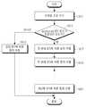
도 18은 본 발명의 일 실시예에 따른 빔 포밍 방식을 지원하는 통신 시스템에서 AP의 동작 과정을 개략적으로 도시한 도면이다;
도 19는 본 발명의 일 실시예에 따른 빔 포밍 방식을 지원하는 통신 시스템에서 STA의 동작 과정을 개략적으로 도시한 도면이다.
상기 도면들을 통해, 유사 참조 번호들은 동일한 혹은 유사한 엘리먼트들과, 특징들 및 구조들을 도시하기 위해 사용된다는 것에 유의해야만 한다.Further aspects, features and advantages of the present invention as set forth above in connection with certain preferred embodiments thereof will become more apparent from the following description, taken in conjunction with the accompanying drawings, in which:
1 schematically illustrates a process for detecting an optimal transmit beam and an optimal receive beam based on an RF beam set in a typical mmWave communication system;
2 is a diagram schematically illustrating a process for detecting an optimal transmit beam and an optimal receive beam based on an RF beam set in a conventional IEEE 802.11ad communication system;
3 is a diagram schematically illustrating a case where an AP does not exist in a coverage of an STA when performing an R-TXSS process in a general IEEE 802.11ad communication system;
4 is a diagram schematically illustrating a transmit sector sweep process in a mmWave communication system supporting a beamforming scheme according to an embodiment of the present invention;
FIG. 5 is a block diagram of an exemplary embodiment of an equalizer scheme in an mmWave communication system according to an embodiment of the present invention.
FIG. 6 is a diagram schematically illustrating a Tx-Rx pair generated based on an extended equalizer scheme in a mmWave communication system supporting a beamforming scheme according to an embodiment of the present invention; FIG.
7 is a histogram schematically illustrating the performance of an equalizer method in a cubic environment-NLOS, far case in an mmWave communication system according to an embodiment of the present invention;
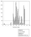
8 is a histogram schematically illustrating the performance of an equalizer method in a cubic environment-LOS, far case in an mmWave communication system according to an embodiment of the present invention;
9 is a histogram schematically illustrating the performance of the equalizer method in a cubic environment-LOS, near case, in an mmWave communication system according to an embodiment of the present invention;
10 is a histogram schematically illustrating the performance of an equalizer method in a living room environment-LOS case in an mmWave communication system according to an embodiment of the present invention;
11 is a histogram schematically illustrating the performance of an equalizer scheme in a living room environment-NLOS case in an mmWave communication system according to an embodiment of the present invention;
12 is a histogram schematically illustrating performance of an equalizer method in a conference room environment-LOS and STA-STA cases in an mmWave communication system according to an embodiment of the present invention;
13 is a histogram schematically illustrating performance of an equalizer method in a conference room environment-LOS, STA-AP case in an mmWave communication system according to an embodiment of the present invention;
FIG. 14 is a histogram schematically illustrating the performance of an equalizer scheme in a conference room environment-NLOS and STA-STA cases in an mmWave communication system according to an embodiment of the present invention;
15 is a histogram schematically illustrating the performance of an equalizer method in a conference room environment-NLOS and STA-AP cases in an mmWave communication system according to an embodiment of the present invention;
16 is a diagram schematically illustrating an internal structure of an AP in a communication system supporting a beamforming scheme according to an embodiment of the present invention;
17 is a diagram schematically illustrating an internal structure of a STA in a communication system supporting a beamforming scheme according to an embodiment of the present invention;
18 is a diagram schematically illustrating an operation procedure of an AP in a communication system supporting a beamforming scheme according to an embodiment of the present invention;
19 is a diagram schematically illustrating an operation procedure of a STA in a communication system supporting a beamforming method according to an embodiment of the present invention.
Throughout the drawings, it should be noted that like reference numerals are used to illustrate the same or similar elements and features and structures.
첨부되는 도면들을 참조하는 하기의 상세한 설명은 청구항들 및 청구항들의 균등들로 정의되는 본 개시의 다양한 실시예들을 포괄적으로 이해하는데 있어 도움을 줄 것이다. 하기의 상세한 설명은 그 이해를 위해 다양한 특정 구체 사항들을 포함하지만, 이는 단순히 예로서만 간주될 것이다. 따라서, 해당 기술 분야의 당업자는 여기에서 설명되는 다양한 실시예들의 다양한 변경들 및 수정들이 본 개시의 범위 및 사상으로부터 벗어남이 없이 이루어질 수 있다는 것을 인식할 것이다. 또한, 공지의 기능들 및 구성들에 대한 설명은 명료성 및 간결성을 위해 생략될 수 있다.The following detailed description, which refers to the accompanying drawings, will serve to provide a comprehensive understanding of the various embodiments of the present disclosure, which are defined by the claims and the equivalents of the claims. The following detailed description includes various specific details for the sake of understanding, but will be considered as exemplary only. Accordingly, those skilled in the art will recognize that various changes and modifications of the various embodiments described herein may be made without departing from the scope and spirit of this disclosure. Furthermore, the descriptions of well-known functions and constructions may be omitted for clarity and conciseness.
하기의 상세한 설명 및 청구항들에서 사용되는 용어들 및 단어들은 문헌적 의미로 한정되는 것이 아니라, 단순히 발명자에 의한 본 개시의 명료하고 일관적인 이해를 가능하게 하도록 하기 위해 사용될 뿐이다. 따라서, 해당 기술 분야의 당업자들에게는 본 개시의 다양한 실시예들에 대한 하기의 상세한 설명은 단지 예시 목적만을 위해 제공되는 것이며, 첨부되는 청구항들 및 상기 청구항들의 균등들에 의해 정의되는 본 개시를 한정하기 위해 제공되는 것은 아니라는 것이 명백해야만 할 것이다.The terms and words used in the following detailed description and in the claims are not intended to be limited to the literal sense, but merely to enable a clear and consistent understanding of the disclosure by the inventor. Thus, it will be apparent to those skilled in the art that the following detailed description of various embodiments of the disclosure is provided for illustrative purposes only, and that the present disclosure, as defined by the appended claims and equivalents of the claims, It should be clear that this is not provided for the sake of clarity.
또한, 본 명세서에서 명백하게 다른 내용을 지시하지 않는 “한”과, “상기”와 같은 단수 표현들은 복수 표현들을 포함한다는 것이 이해될 수 있을 것이다. 따라서, 일 예로, “컴포넌트 표면(component surface)”은 하나 혹은 그 이상의 컴포넌트 표현들을 포함한다.It is also to be understood that the singular forms "a" and "an" above, which do not expressly state otherwise in this specification, include plural representations. Thus, in one example, a " component surface " includes one or more component representations.
또한, 제1, 제2 등과 같이 서수를 포함하는 용어는 다양한 구성요소들을 설명하는데 사용될 수 있지만, 상기 구성요소들은 상기 용어들에 의해 한정되지는 않는다. 상기 용어들은 하나의 구성요소를 다른 구성요소로부터 구별하는 목적으로만 사용된다. 예를 들어, 본 발명의 권리 범위를 벗어나지 않으면서 제1 구성요소는 제2 구성요소로 명명될 수 있고, 유사하게 제2 구성요소도 제1 구성요소로 명명될 수 있다. 및/또는 이라는 용어는 복수의 관련된 기재된 항목들의 조합 또는 복수의 관련된 기재된 항목들 중의 어느 항목을 포함한다.Also, terms including ordinal numbers such as first, second, etc. may be used to describe various elements, but the elements are not limited to these terms. The terms are used only for the purpose of distinguishing one component from another. For example, without departing from the scope of the present invention, the first component may be referred to as a second component, and similarly, the second component may also be referred to as a first component. And / or < / RTI > includes any combination of a plurality of related listed items or any of a plurality of related listed items.
또한, 본 명세서에서 사용한 용어는 단지 특정한 실시 예를 설명하기 위해 사용된 것으로, 본 발명을 한정하려는 의도가 아니다. 단수의 표현은 문맥상 명백하게 다르게 뜻하지 않는 한, 복수의 표현을 포함한다. 본 명세서에서, "포함하다" 또는 "가지다" 등의 용어는 명세서상에 기재된 특징, 숫자, 단계, 동작, 구성요소, 부품 또는 이들을 조합한 것이 존재함을 지정하려는 것이지, 하나 또는 그 이상의 다른 특징들이나 숫자, 단계, 동작, 구성요소, 부품 또는 이들을 조합한 것들의 존재 또는 부가 가능성을 미리 배제하지 않는 것으로 이해되어야 한다.Also, the terminology used herein is for the purpose of describing particular embodiments only and is not intended to be limiting of the invention. The singular expressions include plural expressions unless the context clearly dictates otherwise. In this specification, the terms "comprises" or "having" and the like refer to the presence of stated features, integers, steps, operations, elements, components, or combinations thereof, But do not preclude the presence or addition of one or more other features, integers, steps, operations, elements, components, or combinations thereof.
또한, 별도로 다르게 정의되지 않는 한, 기술적이거나 과학적인 용어를 포함해서 여기서 사용되는 모든 용어들은 본 발명이 속하는 기술 분야에서 통상의 지식을 가진 자에 의해 일반적으로 이해되는 것과 동일한 의미를 가지고 있다. 일반적으로 사용되는 사전에 정의되어 있는 것과 같은 용어들은 관련 기술의 문맥 상 가지는 의미와 일치하는 의미를 가지는 것으로 이해되어야만 한다.Also, unless otherwise defined, all terms used herein, including technical or scientific terms, have the same meaning as commonly understood by one of ordinary skill in the art to which this invention belongs. Terms such as those defined in commonly used dictionaries should be understood to have a meaning consistent with the contextual meaning of the related art.
본 발명의 다양한 실시예들에 따르면, 전자 디바이스는 통신 기능을 포함할 수 있다. 일 예로, 전자 디바이스는 스마트 폰(smart phone)과, 태블릿(tablet) 개인용 컴퓨터(personal computer: PC, 이하 'PC'라 칭하기로 한다)와, 이동 전화기와, 화상 전화기와, 전자책 리더(e-book reader)와, 데스크 탑(desktop) PC와, 랩탑(laptop) PC와, 넷북(netbook) PC와, 개인용 복합 단말기(personal digital assistant: PDA, 이하 'PDA'라 칭하기로 한다)와, 휴대용 멀티미디어 플레이어(portable multimedia player: PMP, 이하 'PMP'라 칭하기로 한다)와, 엠피3 플레이어(mp3 player)와, 이동 의료 디바이스와, 카메라와, 웨어러블 디바이스(wearable device)(일 예로, 헤드-마운티드 디바이스(head-mounted device: HMD, 일 예로 'HMD'라 칭하기로 한다)와, 전자 의류와, 전자 팔찌와, 전자 목걸이와, 전자 앱세서리(appcessory)와, 전자 문신, 혹은 스마트 워치(smart watch) 등이 될 수 있다.According to various embodiments of the invention, the electronic device may comprise a communication function. For example, the electronic device may be a smart phone, a tablet personal computer (PC), a mobile phone, a videophone, an e-book reader e a notebook PC, a netbook PC, a personal digital assistant (PDA), a portable personal computer (PC) A mobile multimedia device, a portable multimedia player (PMP), an MP3 player, a mobile medical device, a camera, a wearable device (e.g., a head- Electronic devices such as a head-mounted device (HMD), an electronic apparel, an electronic bracelet, an electronic necklace, an electronic app apparel, an electronic tattoo, or a smart watch ) And the like.
본 발명의 다양한 실시예들에 따르면, 전자 디바이스는 통신 기능을 가지는 스마트 가정용 기기(smart home appliance)가 될 수 있다. 일 예로, 상기 스마트 가정용 기기는 텔레비젼과, 디지털 비디오 디스크(digital video disk: DVD, 이하 'DVD'라 칭하기로 한다) 플레이어와, 오디오와, 냉장고와, 에어 컨디셔너와, 진공 청소기와, 오븐과, 마이크로웨이브 오븐과, 워셔와, 드라이어와, 공기 청정기와, 셋-탑 박스(set-top box)와, TV 박스 (일 예로, Samsung HomeSyncTM, Apple TVTM, 혹은 Google TVTM)와, 게임 콘솔(gaming console)과, 전자 사전과, 캠코더와, 전자 사진 프레임 등이 될 수 있다.According to various embodiments of the present invention, the electronic device may be a smart home appliance having communication capabilities. For example, the smart home appliance includes a television, a digital video disk (DVD) player, audio, a refrigerator, an air conditioner, a vacuum cleaner, an oven, A microwave oven, a washer, a dryer, an air purifier, a set-top box, a TV box (for example, Samsung HomeSync™ , Apple TV™ or Google TV™ ) a gaming console, an electronic dictionary, a camcorder, an electrophotographic frame, and the like.
본 발명의 다양한 실시예들에 따르면, 전자 디바이스는 의료 기기(일 예로, 자기 공명 혈관 조영술(magnetic resonance angiography: MRA, 이하 'MRA'라 칭하기로 한다) 디바이스와, 자기 공명 화상법(magnetic resonance imaging: MRI, 이하 “MRI”라 칭하기로 한다)과, 컴퓨터 단층 촬영(computed tomography: CT, 이하 'CT'라 칭하기로 한다) 디바이스와, 촬상 디바이스, 혹은 초음파 디바이스)와, 네비게이션(navigation) 디바이스와, 전세계 위치 시스템(global positioning system: GPS, 이하 'GPS'라 칭하기로 한다) 수신기와, 사고 기록 장치(event data recorder: EDR, 이하 'EDR'이라 칭하기로 한다)와, 비행 기록 장치(flight data recorder: FDR, 이하 'FER'이라 칭하기로 한다)와, 자동차 인포테인먼트 디바이스(automotive infotainment device)와, 항해 전자 디바이스(일 예로, 항해 네비게이션 디바이스, 자이로스코프(gyroscope), 혹은 나침반)와, 항공 전자 디바이스와, 보안 디바이스와, 산업용 혹은 소비자용 로봇(robot) 등이 될 수 있다.According to various embodiments of the present invention, the electronic device may be a medical device (e.g., magnetic resonance angiography (MRA) device, magnetic resonance imaging (CT) device, an imaging device, or an ultrasonic device), a navigation device, and a magnetic resonance imaging (MRI) , A global positioning system (GPS) receiver, an event data recorder (EDR), a flight data recorder a recorder: FDR (hereinafter referred to as FER), an automotive infotainment device, a navigation electronic device (e.g., navigation navigation device, gyroscope pe, or compass), an avionics device, a secure device, an industrial or consumer robot, and the like.
본 발명의 다양한 실시예들에 따르면, 전자 디바이스는 통신 기능을 포함하는, 가구와, 빌딩/구조의 일부와, 전자 보드와, 전자 서명 수신 디바이스와, 프로젝터와, 다양한 측정 디바이스들(일 예로, 물과, 전기와, 가스 혹은 전자기 파 측정 디바이스들) 등이 될 수 있다.In accordance with various embodiments of the present invention, an electronic device includes a plurality of devices, including furniture, a portion of a building / structure, an electronic board, an electronic signature receiving device, a projector and various measurement devices (e.g., Water, electricity, gas or electromagnetic wave measuring devices), and the like.
본 발명의 다양한 실시예들에 따르면, 전자 디바이스는 상기에서 설명한 바와 같은 디바이스들의 조합이 될 수 있다. 또한, 본 발명의 바람직한 실시예들에 따른 전자 디바이스는 상기에서 설명한 바와 같은 디바이스에 한정되는 것이 아니라는 것은 당업자에게 자명할 것이다.According to various embodiments of the invention, the electronic device may be a combination of devices as described above. It should also be apparent to those skilled in the art that the electronic device according to the preferred embodiments of the present invention is not limited to the device as described above.
본 발명의 다양한 실시예들에 따르면, 단말기(station: STA, 이하 "STA"라 칭하기로 한다)는 일 예로 전자 디바이스가 될 수 있다.According to various embodiments of the present invention, a station (STA) may be an electronic device, for example.
본 발명의 다양한 실시예들에 따르면, STA는 신호 송신 장치 혹은 신호 수신 장치가 될 수 있고, 억세스 포인트(access point: AP, 이하 "AP"라 칭하기로 한다)는 신호 송신 장치 혹은 신호 수신 장치가 될 수 있다.According to various embodiments of the present invention, the STA may be a signal transmitting device or a signal receiving device, and an access point (AP) may be a signal transmitting device or a signal receiving device .
본 발명의 일 실시예는 빔 포밍(beam forming) 방식을 지원하는 통신 시스템에서 빔 패턴(pattern) 선택 프로세스를 수행하는 장치 및 방법을 제안한다.An embodiment of the present invention proposes an apparatus and method for performing a beam pattern selection process in a communication system supporting a beam forming method.
또한, 본 발명의 일 실시예는 빔 포밍 방식을 지원하는 통신 시스템에서 다운링크 송신 빔 패턴 정보를 기반으로 업링크 송신 빔 패턴을 선택하는 빔 패턴 선택 프로세스를 수행하는 장치 및 방법을 제안한다.Also, an embodiment of the present invention proposes an apparatus and method for performing a beam pattern selection process for selecting an uplink transmission beam pattern based on downlink transmission beam pattern information in a communication system supporting a beamforming scheme.
또한, 본 발명의 일 실시예는 빔 포밍 방식을 지원하는 통신 시스템에서 이중(duplicated) 비콘 송신 구간(beacon transmit interval: BTI, 이하 "BTI"라 칭하기로 한다)을 기반으로 빔 패턴 선택 프로세스를 수행하는 장치 및 방법을 제안한다.In addition, an embodiment of the present invention performs a beam pattern selection process based on a duplicated beacon transmission interval (BTI) in a communication system supporting a beamforming scheme And an apparatus and a method for providing the same.
또한, 본 발명의 일 실시예는 빔 포밍 방식을 지원하는 통신 시스템에서 적어도 두 번의 개시자 송신 섹터 스윕(initiator transmit sector sweep: I-TXSS, 이하 "I-TXSS"라 칭하기로 한다) 프로세스들을 기반으로 빔 패턴 선택 프로세스를 수행하는 장치 및 방법을 제안한다.In addition, one embodiment of the present invention is based on at least two initiator transmit sector sweeps (I-TXSS) processes in a communication system supporting a beamforming scheme A beam pattern selection process is performed.
또한, 본 발명의 일 실시예는 빔 포밍 방식을 지원하는 통신 시스템에서 빔 패턴 선택 시간을 감소시키는 것이 가능한 빔 패턴 선택 프로세스를 수행하는 장치 및 방법을 제안한다.In addition, an embodiment of the present invention proposes an apparatus and method for performing a beam pattern selection process capable of reducing a beam pattern selection time in a communication system supporting a beamforming scheme.
또한, 본 발명의 일 실시예는 빔 포밍 방식을 지원하는 통신 시스템에서 빔 선택을 위한 복잡도를 감소시키는 것이 가능한 빔 패턴 선택 프로세스를 수행하는 장치 및 방법을 제안한다.In addition, an embodiment of the present invention proposes an apparatus and method for performing a beam pattern selection process capable of reducing complexity for beam selection in a communication system supporting a beamforming scheme.
한편, 본 발명의 일 실시예에서 제안하는 장치 및 방법은 롱 텀 에볼루션 (long-term evolution: LTE, 이하 'LTE'라 칭하기로 한다) 이동 통신 시스템과, 롱 텀 에볼루션-어드밴스드 (long-term evolution-advanced: LTE-A, 이하 'LTE-A'라 칭하기로 한다) 이동 통신 시스템과, 인가-보조 억세스(licensed-assisted access: LAA, 이하 " LAA"라 칭하기로 한다)-LTE 이동 통신 시스템과, 고속 하향 링크 패킷 접속(high speed downlink packet access: HSDPA, 이하 'HSDPA'라 칭하기로 한다) 이동 통신 시스템과, 고속 상향 링크 패킷 접속(high speed uplink packet access: HSUPA, 이하 'HSUPA'라 칭하기로 한다) 이동 통신 시스템과, 3세대 프로젝트 파트너쉽 2(3rd generation project partnership 2: 3GPP2, 이하 '3GPP2'라 칭하기로 한다)의 고속 레이트 패킷 데이터(high rate packet data: HRPD, 이하 'HRPD'라 칭하기로 한다) 이동 통신 시스템과, 3GPP2의 광대역 부호 분할 다중 접속(wideband code division multiple access: WCDMA, 이하 'WCDMA'라 칭하기로 한다) 이동 통신 시스템과, 3GPP2의 부호 분할 다중 접속(code division multiple access: CDMA, 이하 'CDMA'라 칭하기로 한다) 이동 통신 시스템과, 국제 전기 전자 기술자 협회(institute of electrical and electronics engineers: IEEE, 이하 'IEEE'라 칭하기로 한다) 802.16ad 통신 시스템과, IEEE 802.16m 통신 시스템과, IEEE 802.16e 통신 시스템과, 진화된 패킷 시스템(evolved packet system: EPS, 이하 'EPS'라 칭하기로 한다)과, 모바일 인터넷 프로토콜(mobile internet protocol: Mobile IP, 이하 'Mobile IP '라 칭하기로 한다) 시스템 등과 같은 다양한 통신 시스템들에 적용 가능하다.Meanwhile, an apparatus and method proposed in an embodiment of the present invention can be applied to a long-term evolution (LTE) mobile communication system, a long-term evolution (LTE) (LTE-A) mobile communication system and a licensed-assisted access (LAA) -LTE mobile communication system, , A high speed downlink packet access (HSDPA) mobile communication system, and a high speed uplink packet access (HSUPA) Speed packet data (HRPD) (hereinafter, referred to as 'HRPD') of a 3rd generation project partnership 2 (3GPP2, hereinafter referred to as 3GPP2) The mobile communication system and the 3GPP2 (WCDMA) mobile communication system and a code division multiple access (CDMA) system of 3GPP2 (hereinafter referred to as " CDMA " ) Mobile communication system, an IEEE 802.16ad communication system, an IEEE 802.16m communication system, an IEEE 802.16e communication system, an IEEE 802.16e communication system, Various communication systems such as an evolved packet system (EPS), a mobile internet protocol (hereinafter referred to as " Mobile IP ") system, Lt; / RTI >
먼저, 본 발명의 일 실시예에서 고려하는 채널 모델(channel model)에 대해서 설명하면 다음과 같다.First, a channel model considered in an embodiment of the present invention will be described as follows.
먼저, 밀리미터파(millimeter wave: mmWave, 이하 " mmWave"라 칭하기로 한다) 대역을 사용하는 통신은 자유 공간에서 경로 손실이 비교적 크게 나타나기 때문에 분산성이 작다는 특성을 가진다.First, communication using a millimeter wave (mmWave) band (hereinafter referred to as " mmWave ") has a characteristic that dispersion is small because a path loss is relatively large in free space.
따라서, mmWave 채널의 특성은 클러스터(cluster) 채널 모델을 사용하여 수학적으로 나타낼 수 있다. 상기 클러스터 채널 모델은 다수 개, 일 예로

여기서, i번째 클러스터에서 형성된 l번째 레이(ray)와 송신 안테나가 형성하는 방위각(azimuth)을


상기와 같이 i번째 클러스터에서 형성된 l번째 레이와 송신 안테나가 형성하는 방위각과, 상기 i번째 클러스터에서 형성된 l번째 레이와 송신 안테나가 형성하는 앙각과, 상기 i번째 클러스터에서 형성된 l번째 레이와 수신 안테나가 형성하는 방위각 및 상기 i번째 클러스터에서 형성된 l번째 레이와 수신 안테나가 형성하는 앙각을 정의할 경우, mmWave 클러스터 채널은 하기 수학식 1과 같이 나타낼 수 있다.As described above, the azimuth angle formed by the l-th ray and the transmitting antenna formed in the i-th cluster, the elevation angle formed by the l-th ray and the transmitting antenna formed in the i-th cluster, And an elevation angle formed by the l-th ray and the reception antenna formed in the i-th cluster, the mmWave cluster channel can be expressed by the following equation (1).

상기 수학식 1에서,

또한, 상기 수학식 1에서


상기 수학식 2에서,
또한, 상기 수학식 2에서, m과 n은 각각 균일 평면 어레이 안테나가 포함하는 안테나 엘리먼트들 중 가로축에서 m번째 안테나 엘리먼트를 나타내는 인덱스와 세로축에서 n번째 안테나 엘리먼트를 나타내는 인덱스이며, 상기 m과 n의 범위는

상기 단일 사용자 단일 스트림 mmWave 통신 시스템에서 수신 신호 y는 하기 수학식 3과 같이 나타낼 수 있다.In the single-user single-stream mmWave communication system, the received signal y may be expressed by Equation (3).

상기 수학식 3에서,


상기 수학식 4에서, s는 송신하고자 하는 데이터를 나타내며,
한편, 기본적으로 mmWave 통신 시스템에서는 다수 개의 송신 안테나 엘리먼트들 및 수신 안테나 엘리먼트들을 사용하지만 일반적으로 RF 체인들의 개수가 안테나 엘리먼트들의 개수보다 작기 때문에, 현실적으로 상기 수학식 1에 나타낸 바와 같은 mmWave 클러스터 채널, 즉 채널
따라서, 커버리지(coverage)를 등방위로 분할하여 RF 빔 집합을 생성하고, 이를 기반으로 최적 송신 빔 및 최적 수신 빔을 검출하는 방식이 하이브리드 빔 포밍 방식을 사용하여 아날로그 빔 포밍 값과 디지털 빔 포밍 값을 정확하게 검출하는 방식 보다 현실적일 수 있으며, 이를 도 1을 참조하여 설명하면 다음과 같다.Therefore, a method of generating an RF beam set by dividing coverage into isotropic fields and detecting an optimal transmission beam and an optimal reception beam based on the generated RF beam set is called a hybrid beamforming method to detect an analog beamforming value and a digital beamforming value It can be more realistic than a method of accurately detecting. This will be described with reference to FIG. 1 as follows.
도 1은 일반적인 mmWave 통신 시스템에서 RF 빔 집합을 기반으로 최적 송신 빔 및 최적 수신 빔을 검출하는 프로세스를 개략적으로 도시한 도면이다.1 is a schematic diagram of a process for detecting an optimal transmit beam and an optimal receive beam based on an RF beam set in a typical mmWave communication system.
도 1을 참조하면, 먼저 커버리지를 등방위로 분할하여 RF 빔 집합(111)을 생성한다. 여기서, 상기 RF 빔 집합(111)은 총 19개의 RF 빔 엘리먼트들, 즉 RF 빔 엘리먼트 #1 내지 RF 빔 엘리먼트 #19를 포함한다. 상기 RF 엘리먼트들 각각에는 해당하는 방위각 정보(az)와 앙각 정보(El)가 매핑되며, 상기 방위각 정보(az)와 앙각 정보(El)를 기반으로 해당하는 커버리지가 결정된다(113).Referring to FIG. 1, first, the RF beam set 111 is generated by dividing the coverage into isotropic regions. Here, the RF beam set 111 includes a total of 19 RF beam elements, that is, RF
따라서, AP 혹은 STA는 상기 RF 빔 집합(111)을 기반으로 섹터 스윕 프로세스(sector sweep process)를 수행하여 최적 송신 빔 혹은 최적 수신 빔을 검출할 수 있다.Accordingly, the AP or the STA can perform a sector sweep process based on the RF beam set 111 to detect an optimal transmission beam or an optimal reception beam.
도 1에서는 일반적인 mmWave 통신 시스템에서 RF 빔 집합을 기반으로 최적 송신 빔 및 최적 수신 빔을 검출하는 프로세스에 대해서 설명하였으며, 다음으로 도 2를 참조하여 일반적인 IEEE 802.11ad 통신 시스템에서 RF 빔 집합을 기반으로 최적 송신 빔 및 최적 수신 빔을 검출하는 프로세스에 대해서 설명하기로 한다.FIG. 1 illustrates a process of detecting an optimal transmission beam and an optimal reception beam based on an RF beam set in a general mmWave communication system. Referring to FIG. 2, a conventional IEEE 802.11ad communication system The process of detecting the optimum transmission beam and the optimum reception beam will be described.
도 2는 일반적인 IEEE 802.11ad 통신 시스템에서 RF 빔 집합을 기반으로 최적 송신 빔 및 최적 수신 빔을 검출하는 프로세스를 개략적으로 도시한 도면이다.2 is a diagram schematically illustrating a process for detecting an optimal transmit beam and an optimal receive beam based on an RF beam set in a conventional IEEE 802.11ad communication system.
도 2를 참조하면, 먼저 섹터 레벨 스윕(sector level sweep: SLS, 이하 "SLS"라 칭하기로 한다) 프로세스의 개시자 송신 섹터 스윕(initiator transmit sector sweep: I-TXSS, 이하 "I-TXSS"라 칭하기로 한다) 프로세스는 비콘 송신 구간(beacon transmit interval: BTI, 이하 "BTI"라 칭하기로 한다)에서 수행된다. 상기 I-TXSS 프로세스에서 AP(211)는 도 2에 도시되어 있는 바와 같이 매 타임 슬롯(time slot)마다 섹터를 RF 빔 집합 내부에서 순서대로 변경해가며 송신한다.Referring to FIG. 2, an initiator transmit sector sweep (I-TXSS) (hereinafter referred to as "I-TXSS") process of a sector level sweep (SLS ) Process is performed in a beacon transmit interval (BTI). In the I-TXSS process, the
또한, STA(213)는 전방향(omni-directional: omni, 이하 "omni"라 칭하기로 한다) 수신 모드에서 신호 수신 프로세스를 수행한다. 여기서, 상기 omni 수신 모드는 모든 방향들에 대해 균등하게 신호를 수신하는 모드를 나타낸다. 상기 STA(213)는 상기 BTI 동안 수신한 수신 신호들 중 최대 이득(gain)을 가지는, 상기 AP의 송식 섹터에 대한 인덱스(index)를 저장한다.Also, the
이렇게, 상기 AP(211)의 송신 섹터 스윕 프로세스가 완료되면, 연관 빔 포밍 트레이닝(association beam forming training: A-BFT, 이하 "A-BFT"라 칭하기로 한다) 구간에서, 상기 STA(213)가 송신 섹터 스윕 프로세스를 수행하고, 상기 AP(211)가 omni 수신 모드로 신호 수신 프로세스를 수행하는 응답자 송신 섹터 스윕(responder transmit sector sweep: R-TXSS, 이하 " R-TXSS"라 칭하기로 한다) 프로세스가 수행된다.When the transmission sector sweep process of the
그런데, 상기 AP(211)가 상기 omni 수신 모드로 신호 수신 프로세스를 수행하게 될 경우, 상기 STA(213)의 송신 전력이 상기 AP(211)의 송신 전력에 비해 상대적으로 낮기 때문에, 상기 STA(213)의 커버리지 내에 상기 AP(211)가 존재하지 않는 경우가 발생할 수 있으며, 이를 도 3을 참조하여 설명하면 다음과 같다.However, when the
도 3은 일반적인 IEEE 802.11ad 통신 시스템에서 R-TXSS 프로세스 수행 시 STA의 커버리지 내에 AP가 존재하지 않는 경우를 개략적으로 도시한 도면이다.3 is a diagram schematically illustrating a case where an AP does not exist in the coverage of an STA when performing an R-TXSS process in a general IEEE 802.11ad communication system.
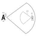
도 3을 참조하면, 먼저, A-BFT 구간에서 STA(311)가 송신 섹터 스윕 프로세스를 수행하고, AP(313)가 omni 수신 모드로 신호 수신 프로세스를 수행하는 R-TXSS 프로세스가 수행된다.3, an R-TXSS process is performed in which the
그런데, 상기 AP(313)가 상기 omni 수신 모드로 신호 수신 프로세스를 수행하게 될 경우, 상기 STA(311)의 송신 전력이 상기 AP(313)의 송신 전력에 비해 상대적으로 낮기 때문에, 상기 STA(311)의 커버리지(315) 내에 상기 AP(313)가 존재하지 않는 경우가 발생할 수 있다.However, when the
이렇게, 상기 STA(311)의 커버리지(315) 내에 상기 AP(313)가 존재하지 않는 경우가 발생할 경우, 상기 R-TXSS 프로세스는 정상적으로 수행될 수 없고, 따라서 빔 설정 역시 불가능해질 수 있다.If the
따라서, 본 발명의 일 실시예에서는 STA의 커버리지 이슈(issue)를 해결하기 위해, STA가 최적 송신 섹터로 신호 송신 프로세스를 수행하고, AP가 omni 수신 모드로 신호 수신 프로세스를 수행하는 것이 아니라 특정 수신 섹터를 기반으로 신호 수신 프로세스를 수행하여 안테나 이득을 증가시키는 방안을 고려하기로 한다.Therefore, in an embodiment of the present invention, in order to solve the coverage issue of the STA, the STA performs the signal transmission process to the optimum transmission sector, and the AP does not perform the signal reception process in the omni reception mode, A method of increasing the antenna gain by performing a signal receiving process based on a sector will be considered.
이렇게, STA가 최적 송신 섹터로 신호 송신 프로세스를 수행하고, AP가 omni 수신 모드로 신호 수신 프로세스를 수행하는 것이 아니라 특정 수신 섹터를 기반으로 신호 수신 프로세스를 수행하여 안테나 이득을 증가시키기 위해서는 STA의 최적 송신 섹터를 추정하는 방식이 필요로 된다.In this way, in order for the STA to perform the signal transmission process to the optimal transmission sector and to perform the signal reception process based on the specific reception sector rather than the AP to perform the signal reception process in the omni reception mode, A method of estimating a transmission sector is required.
상기 STA의 최적 송신 섹터를 추정하는 방식은 채널 호혜(channel reciprocity)를 기반으로 최적 수신 섹터를 추정하는 방식과 동일하게 구현될 수 있다.The method of estimating the optimal transmission sector of the STA can be implemented in the same manner as the method of estimating the optimal reception sector based on channel reciprocity.
먼저, 일반적인 IEEE 802.11ad 통신 시스템에 명시된 빔 포밍 프로토콜에서는 빔 미세 조정 프로토콜(beam refinement protocol: BRP, 이하 "BRP"라 칭하기로 한다) 프로세스에서 개시자 수신 섹터 스윕(initiator receive sector sweep: I-RXSS, 이하 "I-RXSS"라 칭하기로 한다) 프로세스를 통해 STA의 최적 수신 섹터가 결정된다. 여기서, i번째 수신 섹터에 해당하는 수신 신호의 이득

상기 수학식 5에서,


여기서, 상기 STA의 최적 수신 섹터를 검출하는 방식은 하기 수학식 6과 같이 전송률을 최대화하는 수신 섹터를 검출하는 방식으로 표현될 수 있다.Here, a method of detecting an optimal receiving sector of the STA can be expressed as a method of detecting a receiving sector that maximizes a data rate as shown in Equation (6).


상기 수학식 6에서,
한편, 일반적인 IEEE 802.11ad 통신 시스템에 명시된 빔 포밍 프로토콜이 사용될 경우, 상기 STA의 커버리지 이슈를 해결하기 위해 상기 STA의 최적 수신 섹터를 결정하기 위해서는 SLS 프로세스가 수행된 후, 다시 BRP 프로세스까지 수행되어야만 한다.On the other hand, when the beamforming protocol specified in the general IEEE 802.11ad communication system is used, in order to resolve the coverage issue of the STA, the SLS process is performed to determine the optimal receiving sector of the STA, .
따라서, 빔을 설정하기 위해 소모되는 시간이 굉장히 길어지고, 여러 번의 피드백 동작이 수행되기 때문에 레이턴시(latency) 이슈도 발생된다. 또한, STA의 송신 전력이 충분하지 않다면 커버리지 이슈로 인해 빔 설정을 위한 빔 포밍 프로토콜의 전반적인 신뢰도가 저하될 수 있다.Accordingly, since the time consumed to set the beam is extremely long and the feedback operation is performed several times, a latency issue also occurs. Also, if the STA's transmit power is not sufficient, the overall reliability of the beamforming protocol for beam configuration may be degraded due to coverage issues.
따라서, 본 발명의 일 실시예에서는 상기와 같은 일반적인 IEEE 802.11ad 통신 시스템에 명시된 빔 포밍 프로토콜이 사용될 경우 빔 설정시 발생될 수 있는 이슈들을 해결하기 위해 BTI 동안 수신되는 정보를 기반으로 STA의 최적 수신 섹터를 추정하는 방안을 제안한다.Therefore, in an embodiment of the present invention, when the beamforming protocol specified in the general IEEE 802.11ad communication system as described above is used, in order to solve the problems that may occur in the beam setting, based on the information received during the BTI, We propose a method to estimate the sector.
먼저, 도 4를 참조하여 본 발명의 일 실시예에 따른 빔 포밍 방식을 지원하는 mmWave 통신 시스템에서 송신 섹터 스윕 프로세스에 대해서 설명하기로 한다.Referring to FIG. 4, a transmission sector sweep process in a mmWave communication system supporting a beamforming scheme according to an embodiment of the present invention will be described.
도 4는 본 발명의 일 실시예에 따른 빔 포밍 방식을 지원하는 mmWave 통신 시스템에서 송신 섹터 스윕 프로세스를 개략적으로 도시한 도면이다.FIG. 4 is a diagram schematically illustrating a transmission sector sweep process in a mmWave communication system supporting a beamforming scheme according to an embodiment of the present invention. Referring to FIG.
도 4를 참조하면, 먼저 본 발명의 일 실시예에서 제안하는 송신 섹터 스윕 프로세스는 새로운 시구간, 즉 이중 BTI(duplicated BTI, 이하 "duplicated BTI"라 칭하기로 한다)에서 수행되는 송신 섹터 스윕 프로세스이다.Referring to FIG. 4, the transmission sector sweep process proposed in the embodiment of the present invention is a transmission sector sweep process performed in a new time interval, that is, a duplicated BTI (hereinafter referred to as "duplicated BTI") .
일반적인 IEEE 802.11ad 통신 시스템에 정의되어 있는 BTI에서는 송신 섹터 스윕 프로세스가 1번 수행된다. 이렇게, 상기 1번의 송신 섹터 스윕 프로세스 동안 수신되는 정보만으로 STA의 최적 수신 섹터를 추정하는 것은 어려울 수 있다.In the BTI defined in the general IEEE 802.11ad communication system, the transmission sector sweep process is performed once. Thus, it may be difficult to estimate the optimal receiving sector of the STA based only on the information received during the one transmission sector sweep process.
따라서, 본 발명의 일 실시예에서는 새로운 시구간, 즉 duplicated BTI 동안 다수 번, 일 예로 2번 송신 섹터 스윕 프로세스를 수행하고, 상기 송신 섹터 스윕 프로세스를 2번 수행하는 동안 수신되는 정보를 기반으로 STA의 최적 수신 섹터를 추정한다. 즉, 본 발명의 일 실시예에서 제안하는 송신 섹터 스윕 프로세스의 경우 일반적인 IEEE 802.11ad 통신 시스템의 송신 섹터 스윕 프로세스에 비해 STA가 획득할 수 있는 정보량이 2배로 증가하게 되고, 따라서 상기와 같은 증가된 정보량의 정보를 기반으로 상기 STA의 최적 수신 섹터를 추정한다.Accordingly, in an embodiment of the present invention, a new time period, i.e., a plurality of times, e.g., two transmit sector sweep processes during a duplicated BTI, is performed and a STA Lt; / RTI > That is, in the case of the transmission sector sweep process proposed in the embodiment of the present invention, the amount of information that the STA can acquire is twice as much as that of the transmission sector sweep process of the general IEEE 802.11ad communication system, And estimates the optimal receiving sector of the STA based on the information of the amount of information.
상기 duplicated BTI를 지원하기 위해서는, 일반적인 BTI와는 다르게 첫 번째 송신 섹터 스윕 프로세스를 수행할 때 섹터 프레임(sector frame)에 duplicated BTI 필드(field)가 추가될 수 있다.In order to support the duplicated BTI, a duplicated BTI field may be added to a sector frame when the first transmission sector sweep process is performed, unlike a general BTI.
상기 duplicated BTI 필드는 AP가 duplicated BTI를 운영하는지 여부를 지시하는 필드로서, 일 예로 1비트로 구현될 수 있다. 따라서, 상기 duplicated BTI 필드의 필드 값이 일 예로 1일 경우, 상기 AP가 duplicated BTI를 운영함을 지시하며, 상기 duplicated BTI 필드의 필드 값이 일 예로 0일 경우, 상기 AP가 duplicated BTI를 운영하지 않음을 지시한다.The duplicated BTI field indicates whether the AP operates the duplicated BTI, and may be implemented with one bit, for example. Therefore, when the field value of the duplicated BTI field is 1, for example, the AP indicates that the duplicated BTI is operated, and when the field value of the duplicated BTI field is 0, the AP operates the duplicated BTI .
본 발명의 일 실시예에서는 상기 duplicated BTI 필드를 사용하여 상기 AP가 duplicated BTI를 운영하는지 여부를 지시하는 경우를 설명하였으나, 상기 duplicated BTI 필드 뿐만 아니라 다른 다양한 형태들로도 상기 AP가 duplicated BTI를 운영하는지 여부를 지시할 수도 있음은 물론이다. 일 예로, 상기 AP는 해당하는 STA로 전용 메시지를 사용하여 상기 AP가 duplicated BTI를 운영하는지 여부를 지시할 수 있다.In an exemplary embodiment of the present invention, the AP indicates whether the duplicated BTI is used by using the duplicated BTI field. However, it is possible to determine whether the AP operates the duplicated BTI in addition to the duplicated BTI field Of course. For example, the AP may use a dedicated message to the corresponding STA to indicate whether the AP operates a duplicated BTI.
한편, 상기 duplicated BTI가 운영될 경우, STA는 첫 번째 송신 섹터 스윕 프로세스, 즉 AP의 첫 번째 송신 섹터 스윕 프로세스가 완료된 후 A-BFT 구간에서 상기 STA 자신의 송신 섹터 스윕 프로세스를 수행하는 것이 아니라, 상기 duplicated BTI에서 두 번째 송신 섹터 스윕 프로세스, 즉 상기 AP의 두 번째 송신 섹터 스윕 프로세스에 상응하게 수신 섹터 스윕 프로세스를 수행한다. 상기 STA는 상기 AP의 두 번의 송신 섹터 스윕 프로세스들에 상응하게 두 번의 수신 섹터 스윕 프로세스들을 수행하고, 이후 본 발명의 일 실시예에서 제안하는 등화기(equalizer, 이하 "equalizer"라 칭하기로 한다) 방식을 사용하여 상기 STA의 최적 송신 섹터를 추정한다.When the duplicated BTI is operated, the STA does not perform the transmission sector sweep process of the STA itself in the A-BFT interval after the completion of the first transmission sector sweep process, that is, the first transmission sector sweep process of the AP, Performs a receive sector sweep process corresponding to the second transmit sector sweep process in the duplicated BTI, i.e., the second transmit sector sweep process of the AP. The STA performs two receive sector sweep processes corresponding to the two transmit sector sweep processes of the AP and then performs an equalizer (hereinafter referred to as " equalizer ") proposed in an embodiment of the present invention. Scheme to estimate the optimal transmission sector of the STA.
도 4에서는 도시의 편의상, 상기 AP를 "STA1"로 도시하였으며, 상기 STA를 "STA2"로 도시하였음에 유의하여야만 할 것이다.4, it should be noted that for convenience of illustration, the AP is shown as "STA1" and the STA is shown as "STA2".
본 발명의 일 실시예에서는 STA의 커버리지 이슈를 해결하면서도 보다 간단하게 상기 STA의 최적 수신 섹터를 검출하기 위해서, AP가 새로운 구간, 즉 duplicated BTI 동안 I-TXSS 프로세스를 다수 번, 일 예로 2번 수행함으로써 I-RXSS를 가상으로 구현할 수 있는 equalizer 방식을 제안한다. 상기 duplicated BTI에서 획득한 정보를 기반으로 equalizer 방식을 적용할 경우 I-TXSS 프로세스와 I-RXSS 프로세스를 연속적으로 수행한 경우와 동일한 효과를 획득할 수 있다. 즉, duplicated BTI를 운영하고 equalizer 방식을 사용할 경우 AP의 최적 송신 섹터와 STA의 최적 수신 섹터를 추정할 수 있다.In one embodiment of the present invention, in order to more easily detect the optimal receiving sector of the STA while solving the STA coverage problem, the AP performs the I-TXSS process a number of times, for example, twice during a new section, We propose an equalizer method that can implement I-RXSS virtually. When the equalizer method is applied based on the information obtained from the duplicated BTI, it is possible to obtain the same effect as the case where the I-TXSS process and the I-RXSS process are continuously performed. That is, when the duplicated BTI is operated and the equalizer method is used, the optimum transmission sector of the AP and the optimal reception sector of the STA can be estimated.
그러면 여기서 본 발명의 일 실시예에서 제안하는 equalizer 방식에 대해서 구체적으로 설명하면 다음과 같다.Hereinafter, the equalizer method proposed in the embodiment of the present invention will be described in detail as follows.
먼저, 첫 번째 I-TXSS 프로세스는 일반적인 IEEE 802.11ad 통신 시스템의 I-TXSS 프로세스와 동일하게 수행되고, AP의 각 송신 섹터에 대응하는 STA의 수신 신호의 이득을 해당 송신 섹터의 등화 계수(equalizing factor, 이하 "equalizing factor"라 칭하기로 한다)라고 정의하기로 한다. 여기서, i번째 송신 섹터에 대한 equalizing factor

다음으로, 두 번째 I-TXSS 프로세스에서는 일반적인 IEEE 802.11ad 통신 시스템의 I-TXSS 프로세스와는 다르게 STA가 omni 수신 모드로 신호 수신 프로세스를 수행하지 않고, 매 단위 시구간, 일 예로 타임 슬롯마다 수신 섹터를 랜덤(random)하게 변경해가면서 신호 수신 프로세스를 수행한다. 이 때, i번째 송신 섹터와 j번째 수신 섹터를 사용하여 획득되는 수신 신호의 이득을 상기 수학식 7에 나타낸 바와 같은 i번째 송신 섹터에 대한 equalizing factor


상기

여기서, 코시-슈바르츠(Cauchy-Schwarz) 부등식을 상기 수학식 8의 분자와 분모에 동시에 적용하면 상기 수학식 8은 하기 수학식 9와 같이 근사화될 수 있다.Here, if the Cauchy-Schwarz inequality is simultaneously applied to the numerator and denominator of Equation (8), Equation (8) can be approximated as Equation (9).


상기 수학식 9에 나타낸 바와 같이 만약 채널이 단일 경로로만 이루어진다면 등호가 성립한다는 것을 쉽게 알 수 있다. 이는 채널에 도미넌트한(dominant) 경로가 1개만 존재할 경우, equalizing factor가 정상적으로 동작하여 상기 수학식 9, 즉 근사화된
상기 수학식 9에 나타낸 바와 같은 근사식의 최종 형태를 살펴보면, 분모 분자의
따라서, 두 번째 BTI 동안 STA에서 수집한


상기에서 설명한 바와 같이 본 발명의 일 실시예에서 제안하는 equalizer 방식은 채널에 도미넌트한 하나의 경로가 존재할 경우 그 정확도가 높아진다. 따라서, LOS(line of sight)가 존재하거나 채널에 존재하는 경로들의 개수가 적을 경우 본 발명의 일 실시예에서 제안하는 equalizer 방식의 성능은 증가하게 된다.As described above, the equalizer scheme proposed in the embodiment of the present invention increases the accuracy when one dominant path exists in the channel. Therefore, when there is a line of sight (LOS) or the number of paths existing in the channel is small, the performance of the equalizer scheme proposed in the embodiment of the present invention increases.
이와는 달리, 채널에 존재하는 경로들의 개수가 많고, 상기 경로들의 채널 이득이 유사하게 나타날 경우, 상기와 같은 근사식의 정확도의 감소로 인해 STA의 최적 수신 섹터를 정확하게 추정하는 것이 어려워질 수 있다.On the other hand, when the number of paths existing in the channel is large and the channel gains of the paths are similar, it may be difficult to accurately estimate the optimal receiving sector of the STA due to the reduction of the accuracy of the approximate equation.
따라서, 본 발명의 일 실시예에서는 AP가 추가적으로 I-TXSS 프로세스를 수행하여 본 발명의 일 실시예에서 제안하는 equalizer 방식의 성능을 증가시킬 수 있다.Accordingly, in one embodiment of the present invention, the AP performs the I-TXSS process additionally to increase the performance of the equalizer scheme proposed in an embodiment of the present invention.
상기에서 설명한 바와 같은, 본 발명의 일 실시예에서 제안하는 equalizer 방식에서는 AP가 I-TXSS 프로세스를 추가적으로 수행함으로써 STA의 최적 수신 섹터를 추정한다. 하지만, 채널에 존재하는 경로들의 개수가 많고 상기 경로들의 채널 이득이 유사할 경우 상기 equalizer 방식을 사용한다고 할지라도 근사식에서 에러가 증가하여 STA 의 최적 수신 섹터를 추정하는 것이 어려워질 수 있다.In the equalizer scheme proposed in the embodiment of the present invention as described above, the AP additionally performs the I-TXSS process to estimate the optimal receiving sector of the STA. However, even if the number of paths existing in the channel is large and the channel gains of the paths are similar to each other, even if the equalizer method is used, it is difficult to estimate the optimal receiving sector of the STA because the error increases.
따라서, 상기 AP는 상기 equalizer 방식을 수행한 후 I-TXSS 프로세스를 추가적으로 다수 번, 일 예로 두 번 수행하여, 즉 총 3번 I-TXSS 프로세스를 수행하여 STA의 최적 수신 섹터를 추정할 수 있다. 이 경우, 상기 STA의 최적 수신 섹터 추정 성능이 증가된다. 이 경우, 두 번째로 수행되는 I-TXSS 프로세스에서의 수신 이득을 기반으로 세 번째로 수행되는 I-TXSS 프로세스에서 상기 equalizer 방식의 정렬(ordering, 이하 " ordering"라 칭하기로 한다)을 추가함으로써 신호 송신 장치와 신호 수신 장치간의 성능이 우수한 섹터들끼리 페어(pair)가 되는 확률을 증가시키게 된다.Accordingly, the AP may estimate the optimal receiving sector of the STA by performing the I-TXSS process after performing the I-TXSS process a plurality of times, e.g., a total of 3 I-TXSS processes. In this case, the optimal receiving sector estimation performance of the STA is increased. In this case, by adding ordering (hereinafter referred to as "ordering") of the equalizer scheme in the I-TXSS process performed thirdly based on the reception gain in the second I- The probability that the sectors having superior performance between the transmitting apparatus and the signal receiving apparatus becomes a pair is increased.
그러면 여기서 상기 총 3번의 I-TXSS 프로세스를 수행하여 STA의 최적 수신 섹터를 추정하는 방식을 "확장된(extended) equalizer 방식"이라 칭하기로 하며, 상기 확장된 equalizer 방식에 대해서 구체적으로 설명하면 다음과 같다.Hereinafter, a method of estimating the optimal receiving sector of the STA by performing the total of three I-TXSS processes will be referred to as an " extended equalizer method ", and the extended equalizer method will be described in detail. same.
먼저, 첫 번째 I-TXSS 프로세스에서 STA는 AP의 최적 송신 섹터를 검출할 뿐만 아니라 AP의 송신 섹터의 인덱스들을 이득의 크기 순으로 정렬한다.First, in the first I-TXSS process, the STA not only detects the optimal transmission sector of the AP but also arranges the indexes of the transmission sectors of the AP in order of gain.
두 번째 I-TXSS 프로세스에서 상기 STA는 equalizer 방식을 사용하여 가상으로 I-RXSS 프로세스를 수행한 후, 마찬가지로 상기 STA의 수신 섹터의 인덱스들을 이득의 크기 순으로 정렬한다.In the second I-TXSS process, the STA performs the I-RXSS process virtually using the equalizer method, and then similarly arranges the indexes of the received sectors of the STA in order of gain.
여기서, 상기 첫 번째 I-TXSS 프로세스에서 검출된 송신 섹터 인덱스들의 순서(order, 이하 " order"라 칭하기로 한다)와 상기 두 번째 I-TXSS 프로세스에서 검출된 수신 섹터 인덱스들의 order를 기반으로 송/수신 페어(transmit-receive pair: Tx-Rx pair, 이하 "Tx-Rx pair"라 칭하기로 한다)가 생성될 수 있으며, 이를 도 6을 참조하여 설명하면 다음과 같다.Here, it is assumed that the transmission / reception is performed based on the order of the transmission sector indices detected in the first I-TXSS process and the order of the received sector indices detected in the second I-TXSS process, A transmit-receive pair (Tx-Rx pair) (hereinafter referred to as Tx-Rx pair) can be generated, which will be described with reference to FIG.
도 6은 본 발명의 일 실시예에 따른 빔 포밍 방식을 지원하는 mmWave 통신 시스템에서 확장된 equalizer 방식을 기반으로 생성되는 Tx-Rx pair를 개략적으로 도시한 도면이다.FIG. 6 is a diagram schematically illustrating a Tx-Rx pair generated based on an extended equalizer scheme in a mmWave communication system supporting a beamforming scheme according to an embodiment of the present invention. Referring to FIG.
도 6을 참조하면, STA(613)는 확장된 equalizer 방식을 기반으로 첫 번째 I-TXSS 프로세스에서 AP(611)의 최적 송신 섹터를 검출할 뿐만 아니라 상기 AP(611)의 송신 섹터의 인덱스들을 이득의 크기 순으로 정렬한다. 또한, 상기 STA(613)는 두 번째 I-TXSS 프로세스에서 가상으로 I-RXSS 프로세스를 수행한 후, 상기 STA(613)의 수신 섹터의 인덱스들을 이득의 크기 순으로 정렬한다.Referring to FIG. 6, the
그리고 도 6에 도시되어 있는 바와 같이 첫 번째 I-TXSS 프로세스에서 검출된 송신 섹터 인덱스들의 order

한편, 상기 확장된 equalizer 방식의 세 번째 I-TXSS 프로세스에서는, 도 6에서 설명한 바와 같은, 즉 첫 번째 I-TXSS 프로세스 및 두 번째 I-TXSS 프로세스를 수행한 결과를 기반으로 생성된 Tx-Rx pair를 기반으로 송신 섹터와 수신 섹터를 변경해가면서 이득을 측정한다.Meanwhile, in the third I-TXSS process of the extended equalizer scheme, a Tx-Rx pair generated based on the result of performing the first I-TXSS process and the second I-TXSS process as illustrated in FIG. The gain is measured while changing the transmission sector and the reception sector.
이후, STA는 상기 equalizer 방식을 적용할 경우, 가장 큰 결과값을 갖는 수신 섹터를 상기 STA 자신의 최적 수신 섹터로 결정한다.Thereafter, when the equalizer scheme is applied, the STA determines the receiving sector having the largest result value as the optimal receiving sector of the STA itself.
상기에서 설명한 바와 같이 equalizer 방식의 경우 채널에 단일 경로가 아닌 다수 개의 경로들이 존재할 경우, 최적 수신 섹터를 정확하게 추정할 수 있는 확률이 감소될 수 있으며, 따라서 본 발명의 일 실시예에서는 확장된 equalizer 방식을 제안함으로써 최적 수신 섹터를 정확하게 추정할 수 있는 확률을 증가시키게 된다.As described above, in the case of the equalizer method, if there are a plurality of paths other than a single path in the channel, the probability of accurately estimating the best received sector can be reduced. Therefore, in the embodiment of the present invention, The probability of accurately estimating the optimal received sector is increased.
다음으로 본 발명의 일 실시예에 따른 equalizer 방식의 성능에 대해서 설명하면 다음과 같다.Next, the performance of the equalizer method according to an embodiment of the present invention will be described.
먼저, 본 발명의 일 실시예에 따른 equalizer 방식의 성능에 대해서 설명하기에 앞서, 하기에서 설명되는 각종 시뮬레이션(simulation) 결과들은 하기 표 1과 같은 시뮬레이션 환경하에서 획득된 것임에 유의하여야만 할 것이다.Before describing the performance of the equalizer method according to an embodiment of the present invention, it should be noted that the various simulation results described below are obtained under the simulation environment shown in Table 1 below.

상기 표 1에서, System bandwidth는 시스템 대역폭을 나타내며, 1.728 GHz로 설정되고, Tx power는 송신 전력을 나타내며, 10 dBm로 설정되고, Noise figure는 잡음 지수를 나타내며, 10 dB로 설정되고, Antenna model는 안테나 모델을 나타내며, 기본 스티어링 가능 지향성 안테나 모델(Basic steerable directional antenna model)이고, Maximum antenna gain는 최대 안테나 이득을 나타내며, 16dB로 설정되고, Coverage region는 커버리지 영역을 나타내며, 100°로 설정되고, HPBW of the beam sector는 빔 섹터의 HPBW(half power beam width)를 나타내며, 30°로 설정되고, # of beam sectors는 빔 섹터들의 개수를 나타내며, 19로 설정되고, HPBW for the omni mode는 omni 모드에 대한 HPBW를 나타내며, 100°로 설정되고, Maximum antenna gain of the Omni-mode는 omni 모드에 대한 최대 안테나 이득을 나타내며, 7dB로 설정된다.In Table 1, the system bandwidth represents the system bandwidth, is set to 1.728 GHz, Tx power represents the transmission power, is set to 10 dBm, the noise figure represents the noise figure, is set to 10 dB, The maximum antenna gain represents the maximum antenna gain, is set to 16 dB, the coverage region represents the coverage area, is set to 100, and the HPBW of the beam sector represents the HPBW (half power beam width) of the beam sector, is set to 30 °, # of beam sectors represents the number of beam sectors, is set to 19, and HPBW for the omni mode is set to omni mode The maximum antenna gain of the Omni-mode represents the maximum antenna gain for the omni mode and is set to 7dB.
한편, 하기의 시뮬레이션들은 모든 송/수신 섹터 조합들에 대해 최적 송/수신 섹터를 검출하는 전체 탐색(full search, 이하 "full search"라 칭하기로 한다) 방식, I-TXSS 프로세스를 사용하여 최적 송신 섹터를 검출하고, I-RXSS 프로세스를 사용하여 최적 수신 섹터를 검출하는 I-TXSS & I-RXSS 방식, 본 발명의 일 실시예에서 제안하는 equalizer 방식, 채널을 미리 알고 있다고 가정할 경우 최대 이득을 가지는 채널 경로에 상응하게 송/수신 섹터를 결정하는 최대 전력 레이(maximum power ray, 이하 "maximum power ray"라 칭하기로 한다) 방식, 송신 섹터는 I-TXSS 프로세스를 사용하여 검출하고, 수신 섹터는 omni 모드를 사용하여 검출하는 전방향 모드 수신기(omni mode receiver, 이하 "omni mode receiver"라 칭하기로 한다) 방식에 대해서, 전송률, 최적 수신 섹터와 추정 수신 섹터의 이격 정도(mean of angle gap), full search 방식 대비 최적 수신 섹터를 검출하는 확률(matching probability)을 검출하고, 각 방식에서 결정된 수신 섹터 인덱스의 분포를 히스토그램(histogram)으로 나타내었음에 유의하여야만 할 것이다.In the meantime, the following simulations are performed using the full search (hereinafter referred to as " full search ") method for detecting the optimal transmit / receive sector for all transmit / receive sector combinations, I-TXSS & I-RXSS scheme for detecting sectors and detecting an optimal received sector using an I-RXSS process, an equalizer scheme proposed in an embodiment of the present invention, and a maximum gain A maximum power ray (hereinafter referred to as "maximum power ray ") method for determining a transmit / receive sector corresponding to a channel path, a transmit sector is detected using an I-TXSS process, For an omni mode receiver (hereinafter referred to as "omni mode receiver ") system which detects using an omni mode, a transmission rate, a degree of separation between an optimal receiving sector and an estimated receiving sector it should be noted that a probability of detecting an optimal received sector with respect to a mean of angle gap and a full search method is detected and a distribution of the received sector index determined in each method is represented by a histogram.
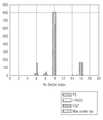
첫 번째로, 큐비클 환경 - NLOS(non LOS), far 케이스(case)에서의 시뮬레이션 결과는 하기 표 2에 나타낸 바와 같다.First, simulation results in the cubicle environment-NLOS (non-LOS) and far case are shown in Table 2 below.

상기 표 2에 나타낸 바와 같이, 큐비클 환경 - NLOS, far 케이스에서 본 발명의 일 실시예에 따른 equalizer 방식이 full search 방식 대비 최적 수신 섹터를 검출하는 확률이 높음을 알 수 있다.As shown in Table 2, in the case of the cubicle environment-NLOS, far case, the equalizer method according to an embodiment of the present invention has a high probability of detecting the optimal receiving sector compared to the full search method.
그리고, 상기 표 2에 나타낸 바와 같은 큐비클 환경 - NLOS, far 케이스에서의 시뮬레이션 결과에 따른, 각 방식에서 결정된 수신 섹터 인덱스의 분포를 도 7을 참조하여 설명하면 다음과 같다.The distribution of the received sector index determined in each method according to the simulation result in the cubic environment-NLOS, far case as shown in Table 2 will be described with reference to FIG.
도 7은 본 발명의 일 실시예에 따른 mmWave 통신 시스템에서 큐비클 환경 - NLOS, far 케이스에서 equalizer 방식의 성능을 개략적으로 도시한 히스토그램이다.FIG. 7 is a histogram schematically illustrating performance of an equalizer method in a cubic environment-NLOS, far case in an mmWave communication system according to an embodiment of the present invention.
도 7을 참조하면, FS는 full search 방식을 나타내며, I-RxSS는 I-TXSS & I-RXSS 방식을 나타내며, EQZ는 equalizer 방식을 나타내며, Max power ray는 maximum power ray 방식을 나타낸다.Referring to FIG. 7, FS denotes a full search method, I-RxSS denotes an I-TXSS & I-RXSS method, EQZ denotes an equalizer method, and Max power ray denotes a maximum power ray method.
도 7에 도시되어 있는 바와 같이, 큐비클 환경 - NLOS, far 케이스에서 본 발명의 일 실시예에 따른 equalizer 방식이 full search 방식 대비 최적 수신 섹터를 검출하는 확률이 높음을 알 수 있다.As shown in FIG. 7, in the case of a cubicle environment-NLOS, far case, the equalizer method according to an embodiment of the present invention has a high probability of detecting an optimal receiving sector compared to a full search method.
두 번째로, 큐비클 환경 - LOS, far 케이스에서의 시뮬레이션 결과는 하기 표 3에 나타낸 바와 같다.Second, simulation results in the cubic environment-LOS, far case are as shown in Table 3 below.

상기 표 3에 나타낸 바와 같이, 큐비클 환경 - LOS, far 케이스에서 본 발명의 일 실시예에 따른 equalizer 방식이 full search 방식 대비 최적 수신 섹터를 검출하는 확률이 높음을 알 수 있다.As shown in Table 3, in the case of the cubic environment-LOS, far case, the equalizer method according to an embodiment of the present invention has a high probability of detecting the optimal receiving sector compared to the full search method.
그리고, 상기 표 3에 나타낸 바와 같은 큐비클 환경 - LOS, far 케이스에서의 시뮬레이션 결과에 따른, 각 방식에서 결정된 수신 섹터 인덱스의 분포를 도 8을 참조하여 설명하면 다음과 같다.The distribution of the received sector index determined in each method according to the simulation result in the cubic environment-LOS, far case as shown in Table 3 will be described with reference to FIG.
도 8은 본 발명의 일 실시예에 따른 mmWave 통신 시스템에서 큐비클 환경 - LOS, far 케이스에서 equalizer 방식의 성능을 개략적으로 도시한 히스토그램이다.8 is a histogram schematically illustrating the performance of the equalizer method in the cubic environment-LOS, far case in the mmWave communication system according to the embodiment of the present invention.
도 8을 참조하면, FS는 full search 방식을 나타내며, I-RxSS는 I-TXSS & I-RXSS 방식을 나타내며, EQZ는 equalizer 방식을 나타내며, Max power ray는 maximum power ray 방식을 나타낸다.Referring to FIG. 8, FS represents a full search method, I-RxSS represents an I-TXSS & I-RXSS method, EQZ represents an equalizer method, and a Max power ray represents a maximum power ray method.
도 8에 도시되어 있는 바와 같이, 큐비클 환경 - LOS, far 케이스에서 본 발명의 일 실시예에 따른 equalizer 방식이 full search 방식 대비 최적 수신 섹터를 검출하는 확률이 높음을 알 수 있다.As shown in FIG. 8, in the case of a cubic environment-LOS, far case, the equalizer method according to an embodiment of the present invention has a high probability of detecting an optimal receiving sector compared to the full search method.
세 번째로, 큐비클 환경 - LOS, near 케이스에서의 시뮬레이션 결과는 하기 표 4에 나타낸 바와 같다.Third, the simulation results in the cubic environment-LOS, near-case are as shown in Table 4 below.

상기 표 4에 나타낸 바와 같이, 큐비클 환경 - LOS, near 케이스에서 본 발명의 일 실시예에 따른 equalizer 방식이 full search 방식 대비 최적 수신 섹터를 검출하는 확률이 높음을 알 수 있다.As shown in Table 4, it can be seen that the equalizer method according to an embodiment of the present invention has a high probability of detecting an optimal receiving sector compared to the full search method in a cubic environment-LOS, near case.
그리고, 상기 표 4에 나타낸 바와 같은 큐비클 환경 - LOS, near 케이스에서의 시뮬레이션 결과에 따른, 각 방식에서 결정된 수신 섹터 인덱스의 분포를 도 9를 참조하여 설명하면 다음과 같다.The distribution of the received sector index determined in each method according to the simulation result in the cubic environment-LOS and near case as shown in Table 4 will be described with reference to FIG.
도 9는 본 발명의 일 실시예에 따른 mmWave 통신 시스템에서 큐비클 환경 - LOS, near 케이스에서 equalizer 방식의 성능을 개략적으로 도시한 히스토그램이다.FIG. 9 is a histogram schematically illustrating the performance of the equalizer method in the cubic environment-LOS and the near case in the mmWave communication system according to the embodiment of the present invention.
도 9를 참조하면, FS는 full search 방식을 나타내며, I-RxSS는 I-TXSS & I-RXSS 방식을 나타내며, EQZ는 equalizer 방식을 나타내며, Max power ray는 maximum power ray 방식을 나타낸다.Referring to FIG. 9, FS represents a full search method, I-RxSS represents an I-TXSS & I-RXSS method, EQZ represents an equalizer method, and a Max power ray represents a maximum power ray method.
도 9에 도시되어 있는 바와 같이, 큐비클 환경 - LOS, near 케이스에서 본 발명의 일 실시예에 따른 equalizer 방식이 full search 방식 대비 최적 수신 섹터를 검출하는 확률이 높음을 알 수 있다.As shown in FIG. 9, it can be seen that the equalizer method according to an embodiment of the present invention in a cubic environment-LOS, near case, has a high probability of detecting an optimal receiving sector compared to the full search method.
그러면 여기서 상기 큐비클 환경 하에서의 시뮬레이션 결과들, 즉 표 2 내지 표 4와, 도 7 내지 도 9에 나타낸 바와 같은 시뮬레이션 결과들에 대해서 정리하면 다음과 같다.Here, the simulation results under the cubic environment, that is, the simulation results as shown in Tables 2 to 4 and FIGS. 7 to 9 are summarized as follows.
먼저, 상기 큐비클 환경 - NLOS, far 케이스에서, equalizer 방식을 사용하여 STA의 최적 수신 섹터를 검출할 확률은 79%로 I-RXSS 프로세스를 사용하여 STA의 최적 수신 섹터를 검출할 확률에 비해 작음을 알 수 있고, 이에 따라 최적 수신 섹터와 추정된 수신 섹터의 이격 정도(mean of angle gap) 역시 5.3°로 상대적으로 큰 값을 갖는 것을 알 수 있다.First, in the cubic environment-NLOS, far case, the probability of detecting the optimal receiving sector of the STA using the equalizer method is 79%, which is smaller than the probability of detecting the optimal receiving sector of the STA using the I-RXSS process As a result, it can be seen that the mean of angle gap between the optimal receiving sector and the estimated receiving sector also has a relatively large value of 5.3 °.
이와는 달리, 큐비클 환경 - LOS, far 케이스는 AP가 STA와 멀리 떨어져 있는 시나리오, 일 예로, AP는 천장에 위치하고 있는 것과 같이 AP와 STA가 멀리 떨어져 시나리오이기 때문에, LOS 경로를 포함하는 섹터가 일 예로 섹터 #11이 된다. 이 때, 본 발명의 일 실시예에 따른 equalizer 방식이 송신 섹터와 수신 섹터의 모든 조합들을 검색하여 최적 송신 섹터 및 최적 수신 섹터를 검출하는 full search 방식에 거의 근접한 성능을 갖는 것을 알 수 있다. 이 경우, 상기 equalizer 방식을 사용하여 STA의 최적 수신 섹터를 검출할 확률은 96%로 굉장히 우수한 성능을 나타내며, 전송률(rate) 역시 상기 full search 방식과 유사함을 알 수 있다.On the other hand, a cubic environment-LOS, the far case is a scenario where the AP is far from the STA, for example, the AP and the STA are far apart scenarios, as the AP is located on the ceiling,
또한, 큐비클 환경 - LOS, near 케이스에서는 STA와 AP간의 거리가 가까운 만큼 LOS가 존재한다는 가정이 성립하게 된다. 따라서, 큐비클 환경 - NLOS, far 케이스 및 큐비클 환경 - LOS, far 케이스와는 달리 AP가 STA와 가까운 거리에 존재하기 때문에 일 예로 섹터 #11 보다 위에 위치하고 있는 섹터 #13이 LOS 경로를 포함하는 섹터가 된다. 이 경우, 본 발명의 일 실시예에 따른 equalizer 방식을 사용하여 검출한 수신 섹터가 최적 수신 섹터와 완벽하게 일치하는 것을 알 수 있다. 이렇게, equalizer 방식을 사용하여 검출한 수신 섹터가 최적 수신 섹터와 완벽하게 일치하는 것은 LOS 경로가 존재할 경우 채널이 도미넌트한 하나의 LOS 경로로 대표된다는 것을 나타낸다. 이와 같은 경우, 상기에서 설명한 바와 같이 본 발명의 일 실시예에 따른 equalizer 방식을 기반으로 최적 수신 섹터를 정확하게 검출할 수 있다는 것을 알 수 있다.In addition, assuming that the LOS exists in the cubic environment - LOS, in the near case, the distance between the STA and the AP is close to the distance. Therefore, unlike the cubic environment-NLOS, far case, and cubic environment-LOS, far case, the AP exists at a close distance from the STA, so that the
네 번째로, 리빙 룸(living room) 환경 - LOS 케이스에서의 시뮬레이션 결과는 하기 표 5에 나타낸 바와 같다.Fourth, the simulation results in the living room environment-LOS case are as shown in Table 5 below.

상기 표 5에 나타낸 바와 같이, 리빙 룸 환경 - LOS 케이스에서 본 발명의 일 실시예에 따른 equalizer 방식이 full search 방식 대비 최적 수신 섹터를 검출하는 확률이 높음을 알 수 있다.As shown in Table 5, in the case of a living room environment-LOS case, the equalizer method according to an embodiment of the present invention has a high probability of detecting an optimal receiving sector compared to the full search method.
그리고, 상기 표 5에 나타낸 바와 같은 리빙 룸 환경 - LOS 케이스에서의 시뮬레이션 결과에 따른, 각 방식에서 결정된 수신 섹터 인덱스의 분포를 도 10을 참조하여 설명하면 다음과 같다.The distribution of the received sector index determined in each method according to the simulation result in the living room environment-LOS case as shown in Table 5 will be described below with reference to FIG.
도 10은 본 발명의 일 실시예에 따른 mmWave 통신 시스템에서 리빙 룸 환경 - LOS 케이스에서 equalizer 방식의 성능을 개략적으로 도시한 히스토그램이다.10 is a histogram schematically illustrating the performance of the equalizer method in the living room environment-LOS case in the mmWave communication system according to the embodiment of the present invention.
도 10을 참조하면, FS는 full search 방식을 나타내며, I-RxSS는 I-TXSS & I-RXSS 방식을 나타내며, EQZ는 equalizer 방식을 나타내며, Max power ray는 maximum power ray 방식을 나타낸다.Referring to FIG. 10, FS represents a full search method, I-RxSS represents an I-TXSS & I-RXSS method, EQZ represents an equalizer method, and a Max power ray represents a maximum power ray method.
도 10에 도시되어 있는 바와 같이, 리빙 룸 환경 - LOS 케이스에서 본 발명의 일 실시예에 따른 equalizer 방식이 full search 방식 대비 최적 수신 섹터를 검출하는 확률이 높음을 알 수 있다.As shown in FIG. 10, in the living room environment-LOS case, the equalizer method according to an embodiment of the present invention has a high probability of detecting an optimal receiving sector compared to the full search method.
다섯 번째로, 리빙 룸 환경 - NLOS 케이스에서의 시뮬레이션 결과는 하기 표 6에 나타낸 바와 같다.Fifth, the simulation results in the living room environment-NLOS case are as shown in Table 6 below.

상기 표 6에 나타낸 바와 같이, 리빙 룸 환경 - NLOS 케이스에서 본 발명의 일 실시예에 따른 equalizer 방식이 full search 방식 대비 최적 수신 섹터를 검출하는 확률이 높음을 알 수 있다.As shown in Table 6, in the case of the living room environment-NLOS case, the equalizer method according to an embodiment of the present invention has a high probability of detecting an optimal receiving sector compared to the full search method.
그리고, 상기 표 6에 나타낸 바와 같은 리빙 룸 환경 - NLOS 케이스에서의 시뮬레이션 결과에 따른, 각 방식에서 결정된 수신 섹터 인덱스의 분포를 도 11을 참조하여 설명하면 다음과 같다.The distribution of the received sector index determined in each method according to the simulation result in the living room environment-NLOS case as shown in Table 6 will be described with reference to FIG.
도 11은 본 발명의 일 실시예에 따른 mmWave 통신 시스템에서 리빙 룸 환경 - NLOS 케이스에서 equalizer 방식의 성능을 개략적으로 도시한 히스토그램이다.11 is a histogram schematically illustrating performance of an equalizer method in a living room environment-NLOS case in an mmWave communication system according to an embodiment of the present invention.
도 11을 참조하면, FS는 full search 방식을 나타내며, I-RxSS는 I-TXSS & I-RXSS 방식을 나타내며, EQZ는 equalizer 방식을 나타내며, Max power ray는 maximum power ray 방식을 나타낸다.11, FS represents a full search method, I-RxSS represents an I-TXSS & I-RXSS method, EQZ represents an equalizer method, and a Max power ray represents a maximum power ray method.
도 11에 도시되어 있는 바와 같이, 리빙 룸 환경 - NLOS 케이스에서 본 발명의 일 실시예에 따른 equalizer 방식이 full search 방식 대비 최적 수신 섹터를 검출하는 확률이 높음을 알 수 있다.As shown in FIG. 11, in the case of a living room environment-NLOS, the equalizer method according to an embodiment of the present invention has a high probability of detecting an optimal receiving sector compared to a full search method.
그러면 여기서 상기 리빙 룸 환경 하에서의 시뮬레이션 결과들, 즉 표 5 및 표 6과, 도 10 및 도 11에 나타낸 바와 같은 시뮬레이션 결과들에 대해서 정리하면 다음과 같다.Here, the simulation results under the living room environment, that is, the simulation results as shown in Tables 5 and 6 and FIGS. 10 and 11, are summarized as follows.
먼저, 상기 리빙 룸 환경 하에서의 시나리오들은 LOS 경로의 유무에 따라서 분류될 수 있다. 일 예로, LOS 경로가 존재하는 경우의 히스토그램, 즉 도 10에 도시되어 있는 히스토그램을 살펴보면 LOS 경로를 포함하는 섹터 #1이 항상 STA의 최적 수신 섹터가 되는 것을 알 수 있다. 이 때, 본 발명의 일 실시예에 따른 equalizer 방식이 사용될 경우 약 77% 정도의 확률로 STA의 최적 수신 섹터를 검출할 있고, full search 방식 대비 88% 정도의 전송률(rate)을 획득할 수 있다.First, scenarios under the living room environment can be classified according to the presence or absence of the LOS path. For example, if the histogram of the LOS path exists, that is, the histogram shown in FIG. 10, it can be seen that the
이와는 달리, LOS 경로가 존재하지 않는 경우의 히스토그램, 즉 도 11에 도시되어 있는 히스토그램을 살펴보면, STA의 최적 수신 섹터는 천장의 반사를 고려한 섹터 #11 및 섹터 #13이 됨을 알 수 있다. 또한, 벽에서 반사되는 경로도 존재하기 때문에 채널은 하나의 도미넌트한 경로로 대표될 수 없게 된다. 이에 따라, 본 발명의 일 실시예에서 제안하는 equalizer 방식의 성능이 61%로 LOS 경로가 존재할 경우 보다 약 16% 정도 떨어지는 것을 알 수 있고, 따라서 최적 수신 섹터와 추정 수신 섹터의 이격 정도 역시 커지는 것을 알 수 있다.In contrast, if the histogram of the case where the LOS path does not exist, that is, the histogram shown in FIG. 11, the optimal receiving sector of the STA is
여섯 번째로, 컨퍼런스 룸(conference room) 환경 - LOS, STA-STA 케이스에서의 시뮬레이션 결과는 하기 표 7에 나타낸 바와 같다.Sixth, the results of the simulation in the conference room environment-LOS and STA-STA cases are as shown in Table 7 below.

상기 표 7에 나타낸 바와 같이, 컨퍼런스 룸 환경 - LOS, STA-STA 케이스에서 본 발명의 일 실시예에 따른 equalizer 방식이 full search 방식 대비 최적 수신 섹터를 검출하는 확률이 높음을 알 수 있다.As shown in Table 7, in the conference room environment-LOS and STA-STA cases, the equalizer method according to an embodiment of the present invention has a high probability of detecting an optimal received sector compared to the full search method.
그리고, 상기 표 7에 나타낸 바와 같은 컨퍼런스 룸 환경 - LOS, STA-STA 케이스에서의 시뮬레이션 결과에 따른, 각 방식에서 결정된 수신 섹터 인덱스의 분포를 도 12를 참조하여 설명하면 다음과 같다.The distribution of the received sector index determined in each method according to the simulation result in the case of the conference room environment-LOS and STA-STA as shown in Table 7 will be described with reference to FIG.
도 12는 본 발명의 일 실시예에 따른 mmWave 통신 시스템에서 컨퍼런스 룸 환경 - LOS, STA-STA 케이스에서 equalizer 방식의 성능을 개략적으로 도시한 히스토그램이다.12 is a histogram schematically illustrating the performance of an equalizer method in a conference room environment-LOS and STA-STA cases in an mmWave communication system according to an embodiment of the present invention.
도 12를 참조하면, FS는 full search 방식을 나타내며, I-RxSS는 I-TXSS & I-RXSS 방식을 나타내며, EQZ는 equalizer 방식을 나타내며, Max power ray는 maximum power ray 방식을 나타낸다.Referring to FIG. 12, FS denotes a full search method, I-RxSS denotes an I-TXSS & I-RXSS method, EQZ denotes an equalizer method, and a Max power ray denotes a maximum power ray method.
도 12에 도시되어 있는 바와 같이, 컨퍼런스 룸 환경 - LOS, STA-STA 케이스에서 본 발명의 일 실시예에 따른 equalizer 방식이 full search 방식 대비 최적 수신 섹터를 검출하는 확률이 높음을 알 수 있다.As shown in FIG. 12, in the conference room environment-LOS and STA-STA cases, the equalizer method according to an embodiment of the present invention has a high probability of detecting the best received sector compared to the full search method.
일곱 번째로, 컨퍼런스 룸 환경 - LOS, STA-AP 케이스에서의 시뮬레이션 결과는 하기 표 8에 나타낸 바와 같다.Seventh, the simulation results in the conference room environment-LOS and STA-AP cases are as shown in Table 8 below.

상기 표 8에 나타낸 바와 같이, 컨퍼런스 룸 환경 - LOS, STA-AP 케이스에서 본 발명의 일 실시예에 따른 equalizer 방식이 full search 방식 대비 최적 수신 섹터를 검출하는 확률이 높음을 알 수 있다.As shown in Table 8, in the conference room environment-LOS and STA-AP cases, the equalizer method according to an embodiment of the present invention has a high probability of detecting the best received sector compared to the full search method.
그리고, 상기 표 8에 나타낸 바와 같은 컨퍼런스 룸 환경 - LOS, STA-AP 케이스에서의 시뮬레이션 결과에 따른, 각 방식에서 결정된 수신 섹터 인덱스의 분포를 도 13을 참조하여 설명하면 다음과 같다.The distribution of the received sector indexes determined in the respective methods according to the simulation results in the conference room environment-LOS and STA-AP cases as shown in Table 8 will be described with reference to FIG.
도 13은 본 발명의 일 실시예에 따른 mmWave 통신 시스템에서 컨퍼런스 룸 환경 - LOS, STA-AP 케이스에서 equalizer 방식의 성능을 개략적으로 도시한 히스토그램이다.FIG. 13 is a histogram schematically illustrating performance of an equalizer method in a conference room environment-LOS and STA-AP cases in an mmWave communication system according to an embodiment of the present invention.
도 13을 참조하면, FS는 full search 방식을 나타내며, I-RxSS는 I-TXSS & I-RXSS 방식을 나타내며, EQZ는 equalizer 방식을 나타내며, Max power ray는 maximum power ray 방식을 나타낸다.Referring to FIG. 13, FS denotes a full search method, I-RxSS denotes an I-TXSS & I-RXSS method, EQZ denotes an equalizer method, and a Max power ray denotes a maximum power ray method.
도 13에 도시되어 있는 바와 같이, 컨퍼런스 룸 환경 - LOS, STA-AP 케이스에서 본 발명의 일 실시예에 따른 equalizer 방식이 full search 방식 대비 최적 수신 섹터를 검출하는 확률이 높음을 알 수 있다.As shown in FIG. 13, in the conference room environment-LOS and STA-AP cases, the equalizer method according to an embodiment of the present invention has a high probability of detecting the best received sector compared to the full search method.
그러면 여기서 상기 컨퍼런스 룸 환경 - LOS 케이스에서의 시뮬레이션 결과들, 즉 표 7 및 표 8과, 도 12 및 도 13에 나타낸 바와 같은 시뮬레이션 결과들에 대해서 정리하면 다음과 같다.Here, the simulation results in the conference room environment-LOS case, that is, the simulation results as shown in Tables 7 and 8 and FIGS. 12 and 13 are summarized as follows.
먼저, 컨퍼런스 룸 환경에서 LOS 경로가 존재하는 경우, STA-STA 케이스 및 STA-AP 케이스 모두에서 본 발명의 일 실시예에 따른 equalizer 방식의 성능이 굉장히 좋다는 것을 알 수 있다. 상기 STA-STA 케이스에서 LOS 경로를 포함하는 수신 섹터는 섹터 #1이 되고, 상기 STA-AP 케이스에서 LOS 경로를 포함하는 수신 섹터는 섹터 #13이 되는데, 상기 STA-STA 케이스에서는 STA의 최적 수신 섹터가 상기 섹터 #1이 되고, 상기 STA-AP 케이스에서는 STA의 최적 수신 섹터가 상기 섹터 #13이 됨을 알 수 있다.First, if there is an LOS path in a conference room environment, it can be seen that the performance of the equalizer method according to an embodiment of the present invention is very good in both the STA-STA case and the STA-AP case. In the STA-STA case, the receiving sector including the LOS path is
이와 같이, 1개의 섹터로 최적 수신 섹터가 집중되는 경우 상기 equalizer 방식의 성능이 우수함을 알 수 있다.As described above, when the optimum receiving sector is concentrated in one sector, it can be seen that the performance of the equalizer method is excellent.
여덟 번째로, 컨퍼런스 룸 환경 - NLOS, STA-STA 케이스에서의 시뮬레이션 결과는 하기 표 9에 나타낸 바와 같다.Eighth, the simulation results in the conference room environment-NLOS and STA-STA cases are as shown in Table 9 below.

상기 표 9에 나타낸 바와 같이, 컨퍼런스 룸 환경 - NLOS, STA-STA 케이스에서 본 발명의 일 실시예에 따른 equalizer 방식이 full search 방식 대비 최적 수신 섹터를 검출하는 확률이 높음을 알 수 있다.As shown in Table 9, in the conference room environment-NLOS and STA-STA cases, it can be seen that the equalizer method according to an embodiment of the present invention has a high probability of detecting the best received sector compared to the full search method.
그리고, 상기 표 9에 나타낸 바와 같은 컨퍼런스 룸 환경 - NLOS, STA-STA 케이스에서의 시뮬레이션 결과에 따른, 각 방식에서 결정된 수신 섹터 인덱스의 분포를 도 14를 참조하여 설명하면 다음과 같다.The distribution of the received sector index determined in each method according to the simulation result in the case of the conference room environment-NLOS and STA-STA as shown in Table 9 will be described with reference to FIG.
도 14는 본 발명의 일 실시예에 따른 mmWave 통신 시스템에서 컨퍼런스 룸 환경 - NLOS, STA-STA 케이스에서 equalizer 방식의 성능을 개략적으로 도시한 히스토그램이다.FIG. 14 is a histogram schematically illustrating the performance of the equalizer method in the conference room environment-NLOS and STA-STA cases in the mmWave communication system according to an embodiment of the present invention.
도 14를 참조하면, FS는 full search 방식을 나타내며, I-RxSS는 I-TXSS & I-RXSS 방식을 나타내며, EQZ는 equalizer 방식을 나타내며, Max power ray는 maximum power ray 방식을 나타낸다.14, FS represents a full search method, I-RxSS represents an I-TXSS & I-RXSS method, EQZ represents an equalizer method, and a Max power ray represents a maximum power ray method.
도 14에 도시되어 있는 바와 같이, 컨퍼런스 룸 환경 - NLOS, STA-STA 케이스에서 본 발명의 일 실시예에 따른 equalizer 방식이 full search 방식 대비 최적 수신 섹터를 검출하는 확률이 높음을 알 수 있다.As shown in FIG. 14, in the conference room environment-NLOS and STA-STA cases, the equalizer method according to an embodiment of the present invention has a high probability of detecting an optimal receiving sector compared to the full search method.
아홉 번째로, 컨퍼런스 룸 환경 - NLOS, STA-AP 케이스에서의 시뮬레이션 결과는 하기 표 10에 나타낸 바와 같다.Ninth, the simulation results in the conference room environment-NLOS and STA-AP cases are as shown in Table 10 below.

상기 표 10에 나타낸 바와 같이, 컨퍼런스 룸 환경 - NLOS, STA-AP 케이스에서 본 발명의 일 실시예에 따른 equalizer 방식이 full search 방식 대비 최적 수신 섹터를 검출하는 확률이 높음을 알 수 있다.As shown in Table 10, in the conference room environment-NLOS and STA-AP cases, the equalizer method according to an embodiment of the present invention has a high probability of detecting an optimal receiving sector compared to the full search method.
그리고, 상기 표 10에 나타낸 바와 같은 컨퍼런스 룸 환경 - NLOS, STA-AP 케이스에서의 시뮬레이션 결과에 따른, 각 방식에서 결정된 수신 섹터 인덱스의 분포를 도 15를 참조하여 설명하면 다음과 같다.The distribution of the received sector index determined in each method according to the simulation result in the case of the conference room environment-NLOS and STA-AP as shown in Table 10 will be described with reference to FIG.
도 15는 본 발명의 일 실시예에 따른 mmWave 통신 시스템에서 컨퍼런스 룸 환경 - NLOS, STA-AP 케이스에서 equalizer 방식의 성능을 개략적으로 도시한 히스토그램이다.FIG. 15 is a histogram schematically illustrating performance of an equalizer method in a conference room environment-NLOS and STA-AP cases in an mmWave communication system according to an embodiment of the present invention.
도 15를 참조하면, FS는 full search 방식을 나타내며, I-RxSS는 I-TXSS & I-RXSS 방식을 나타내며, EQZ는 equalizer 방식을 나타내며, Max power ray는 maximum power ray 방식을 나타낸다.Referring to FIG. 15, FS represents a full search method, I-RxSS represents an I-TXSS & I-RXSS method, EQZ represents an equalizer method, and a Max power ray represents a maximum power ray method.
도 15에 도시되어 있는 바와 같이, 컨퍼런스 룸 환경 - NLOS, STA-AP 케이스에서 본 발명의 일 실시예에 따른 equalizer 방식이 full search 방식 대비 최적 수신 섹터를 검출하는 확률이 높음을 알 수 있다.As shown in FIG. 15, in the conference room environment-NLOS and STA-AP cases, it is found that the equalizer method according to an embodiment of the present invention has a high probability of detecting the optimal receiving sector compared to the full search method.
그러면 여기서 상기 컨퍼런스 룸 환경 - NLOS 케이스에서의 시뮬레이션 결과들, 즉 표 9 및 표 10과, 도 14 및 도 15에 나타낸 바와 같은 시뮬레이션 결과들에 대해서 정리하면 다음과 같다.Here, the simulation results in the conference room environment-NLOS case, that is, the simulation results as shown in Tables 9 and 10 and FIGS. 14 and 15, are summarized as follows.
먼저, 상기 컨퍼런스 룸 환경에서는 LOS가 존재하지 않는 경우, STA-STA 케이스 및 STA-AP 케이스 모두 본 발명의 일 실시예에 따른 equalizer 방식의 성능이 비교적 많이 감소되는 것을 알 수 있다. 이와 같이 equalizer 방식의 성능이 비교적 많이 감소되는 이유는 상기 컨퍼런스 룸 환경에서 채널 모델이 고려하고 있는 다양한 반사 경로들로 인해 채널이 하나의 경로로 대표되는 것이 어렵기 때문이다. 따라서, 상기 equalizer 방식의 근사식의 정확도가 감소하게 되어, 상기 equalizer 방식의 성능이 저하되는 것이다.First, when the LOS is not present in the conference room environment, the performance of the equalizer method according to an exemplary embodiment of the present invention is significantly reduced in both the STA-STA case and the STA-AP case. The reason why the performance of the equalizer method is relatively reduced is that it is difficult for the channel to be represented by one path due to various reflection paths considered by the channel model in the conference room environment. Therefore, the accuracy of the approximate equation of the equalizer method is reduced, and the performance of the equalizer method is lowered.
따라서, 본 발명의 일 실시예에서는 상기 equalizer 방식의 성능 저하 이슈를 해결하기 위해 확장된 equalizer 방식을 제안한 바 있으며, 상기 확장된 equalizer 방식은 AP가 추가적으로 I-TXSS 프로세스를 다수 번 더 수행하고, ordering 방식을 적용함으로써 상기 equalizer 방식에 비해 향상된 성능을 획득할 수 있다.Therefore, in an embodiment of the present invention, an extended equalizer method has been proposed to solve the performance degradation problem of the equalizer method. In the extended equalizer method, the AP further performs the I-TXSS process a plurality of times, The improved performance can be obtained as compared with the equalizer method.
따라서, 상기 확장된 equalizer 방식의 성능 향상을 확인하기 위해서, 상기 equalizer 방식이 사용될 경우 그 성능이 가장 낮게 나타난 3개의 NLOS 시나리오들에 대해서 상기 확장된 equalizer 방식을 적용하고, 각각의 NLOS 시나리오에서 상기 확장된 equalizer 방식의 full search 방식 대비 최적 수신 섹터를 검출하는 확률을 살펴보면 하기 표 11과 같이 나타남을 알 수 있다.Therefore, in order to confirm the performance improvement of the extended equalizer scheme, the extended equalizer scheme is applied to three NLOS scenarios in which the performance is lowest when the equalizer scheme is used, and the extended The probability of detecting the best received sector compared to the full search method of the equalizer method is shown in Table 11 below.

상기 표 11에서, 3 I-TxSS는 equalizer 방식이 수행된 후 한 번의 ordering 방식이 수행되는 확장된 equalizer 방식을 사용하여 최적 수신 섹터가 검출될 경우의 결과를 나타내고, 4 I-TxSS는 상기 3 I-TxSS의 결과에 한 번 더 ordering 방식을 사용하여 최적 수신 섹터가 검출될 경우의 결과를 나타낸다.In Table 11, 3 I-TxSS denotes a result obtained when an optimal received sector is detected using an extended equalizer scheme in which an ordering scheme is performed after the equalizer scheme is performed, and 4 I-TxSS denotes a result obtained when the 3 I -TxSS shows the result when the optimal receiving sector is detected using the ordering method once more.
상기 표 11에 나타낸 바와 같은 3개의 NLOS 시나리오들에서 3 I-TxSS의 경우, 상기 equalizer 방식만 사용할 경우에 비해 최적 수신 섹터를 검출할 확률이 약 50% 증가하는 것을 알 수 있다.In the case of 3 I-TxSS in the three NLOS scenarios shown in Table 11, it can be seen that the probability of detecting an optimal received sector is increased by about 50% as compared with the case of using only the equalizer method.
다음으로, 본 발명의 일 실시예에 따른 빔 포밍 방식을 지원하는 통신 시스템에서 AP의 내부 구조에 대해서 설명하기로 한다.Next, an internal structure of an AP in a communication system supporting a beamforming method according to an embodiment of the present invention will be described.
도 16은 본 발명의 일 실시예에 따른 빔 포밍 방식을 지원하는 통신 시스템에서 AP의 내부 구조를 개략적으로 도시한 도면이다.16 is a diagram schematically illustrating an internal structure of an AP in a communication system supporting a beamforming method according to an embodiment of the present invention.
도 16을 참조하면, AP(1600)는 송신기(1611)와, 제어기(1613)와, 수신기(1615)와, 저장 유닛(1617)을 포함한다.16, the
먼저, 상기 제어기(1613)는 상기 AP(1600)의 전반적인 동작을 제어하며, 특히 본 발명의 일 실시예에 따른 빔 포밍 방식을 지원하는 통신 시스템에서 빔 선택 프로세스를 수행하는 동작에 관련된 동작을 제어한다. 본 발명의 일 실시예에 따른 빔 포밍 방식을 지원하는 통신 시스템에서 빔 선택 프로세스를 수행하는 동작에 관련된 동작에 대해서는 도 1 내지 도 15에서 설명한 바와 동일하므로 여기서는 그 상세한 설명을 생략하기로 한다.First, the
상기 송신기(1611)는 상기 제어기(1613)의 제어에 따라 상기 빔 포밍 방식을 지원하는 통신 시스템이 포함하는 다른 엔터티들, 일 예로 STA 등과 같은 다른 엔터티들로 각종 신호 및 각종 메시지들을 송신한다. 여기서, 상기 송신기(1611)가 송신하는 각종 신호 및 각종 메시지들은 도 1 내지 도 15에서 설명한 바와 동일하므로 여기서는 그 상세한 설명을 생략하기로 한다.Under the control of the
또한, 상기 수신기(1615)는 상기 제어기(1613)의 제어에 따라 상기 빔 포밍 방식을 지원하는 통신 시스템에서 포함하는 다른 엔터티들, 일 예로 STA 등과 같은 다른 엔터티들로부터 각종 신호 및 각종 메시지들을 수신한다. 여기서, 상기 수신기(1615)가 수신하는 각종 신호 및 각종 메시지들은 도 1 내지 도 15에서 설명한 바와 동일하므로 여기서는 그 상세한 설명을 생략하기로 한다.In addition, the
상기 저장 유닛(1617)은 상기 제어기(1613)의 제어에 따라 본 발명의 일 실시예에 따른 빔 포밍 방식을 지원하는 통신 시스템에서 빔 선택 프로세스를 수행하는 동작에 관련된 동작에 관련된 프로그램과 각종 데이터 등을 저장한다.The
또한, 상기 저장 유닛(1617)은 상기 수신기(1615)가 상기 다른 엔터티들로부터 수신한 각종 신호 및 각종 메시지들을 저장한다.In addition, the
한편, 도 16에는 상기 AP(1600)가 상기 송신기(1611)와, 제어기(1613)와, 수신기(1615)와, 저장 유닛(1617)과 같이 별도의 유닛들로 구현된 경우가 도시되어 있으나, 상기 AP(1600)는 상기 송신기(1611)와, 제어기(1613)와, 수신기(1615)와, 저장 유닛(1617) 중 적어도 두 개가 통합된 형태로 구현 가능함은 물론이다. 또한, 상기 AP(1600)는 1개의 프로세서로 구현될 수도 있음은 물론이다.16 shows a case where the
도 16에서는 본 발명의 일 실시예에 따른 빔 포밍 방식을 지원하는 통신 시스템에서 AP의 내부 구조에 대해서 설명하였으며, 다음으로 도 17을 참조하여 본 발명의 일 실시예에 따른 빔 포밍 방식을 지원하는 통신 시스템에서 STA의 내부 구조에 대해서 설명하기로 한다.16 illustrates an internal structure of an AP in a communication system supporting a beamforming scheme according to an embodiment of the present invention. Referring to FIG. 17, the AP supports a beamforming scheme according to an embodiment of the present invention The internal structure of the STA in the communication system will be described.
도 17은 본 발명의 일 실시예에 따른 빔 포밍 방식을 지원하는 통신 시스템에서 STA의 내부 구조를 개략적으로 도시한 도면이다.17 is a diagram schematically illustrating an internal structure of a STA in a communication system supporting a beamforming scheme according to an embodiment of the present invention.
도 17을 참조하면, STA(1700)는 송신기(1711)와, 제어기(1713)와, 수신기(1715)와, 저장 유닛(1717)을 포함한다.17, the
먼저, 상기 제어기(1713)는 상기 STA(1700)의 전반적인 동작을 제어하며, 특히 본 발명의 일 실시예에 따른 빔 포밍 방식을 지원하는 통신 시스템에서 빔 선택 프로세스를 수행하는 동작에 관련된 동작을 제어한다. 본 발명의 일 실시예에 따른 빔 포밍 방식을 지원하는 통신 시스템에서 빔 선택 프로세스를 수행하는 동작에 관련된 동작에 대해서는 도 1 내지 도 15에서 설명한 바와 동일하므로 여기서는 그 상세한 설명을 생략하기로 한다.First, the
상기 송신기(1711)는 상기 제어기(1713)의 제어에 따라 상기 빔 포밍 방식을 지원하는 통신 시스템이 포함하는 다른 엔터티들, 일 예로 AP 등과 같은 다른 엔터티들로 각종 신호 및 각종 메시지들을 송신한다. 여기서, 상기 송신기(1711)가 송신하는 각종 신호 및 각종 메시지들은 도 1 내지 도 15에서 설명한 바와 동일하므로 여기서는 그 상세한 설명을 생략하기로 한다.Under the control of the
또한, 상기 수신기(1715)는 상기 제어기(1713)의 제어에 따라 상기 빔 포밍 방식을 지원하는 통신 시스템에서 포함하는 다른 엔터티들, 일 예로 AP 등과 같은 다른 엔터티들로부터 각종 신호 및 각종 메시지들을 수신한다. 여기서, 상기 수신기(1715)가 수신하는 각종 신호 및 각종 메시지들은 도 1 내지 도 15에서 설명한 바와 동일하므로 여기서는 그 상세한 설명을 생략하기로 한다.In addition, the
상기 저장 유닛(1717)은 상기 제어기(1713)의 제어에 따라 본 발명의 일 실시예에 따른 빔 포밍 방식을 지원하는 통신 시스템에서 빔 선택 프로세스를 수행하는 동작에 관련된 동작에 관련된 프로그램과 각종 데이터 등을 저장한다.The
또한, 상기 저장 유닛(1717)은 상기 수신기(1715)가 상기 다른 엔터티들로부터 수신한 각종 신호 및 각종 메시지들을 저장한다.In addition, the
한편, 도 17에는 상기 STA(1700)가 상기 송신기(1711)와, 제어기(1713)와, 수신기(1715)와, 저장 유닛(1717)과 같이 별도의 유닛들로 구현된 경우가 도시되어 있으나, 상기 STA(1700)는 상기 송신기(1711)와, 제어기(1713)와, 수신기(1715)와, 저장 유닛(1717) 중 적어도 두 개가 통합된 형태로 구현 가능함은 물론이다. 또한, 상기 STA(1700)는 1개의 프로세서로 구현될 수도 있음은 물론이다.17 shows a case where the
도 17에서는 본 발명의 일 실시예에 따른 빔 포밍 방식을 지원하는 통신 시스템에서 STA의 내부 구조에 대해서 설명하였으며, 다음으로 도 18을 참조하여 본 발명의 일 실시예에 따른 빔 포밍 방식을 지원하는 통신 시스템에서 AP의 동작 과정에 대해서 설명하기로 한다.17 illustrates an internal structure of a STA in a communication system supporting a beamforming scheme according to an embodiment of the present invention. Referring to FIG. 18, the STA supports a beamforming scheme according to an embodiment of the present invention An operation process of the AP in the communication system will be described.
도 18은 본 발명의 일 실시예에 따른 빔 포밍 방식을 지원하는 통신 시스템에서 AP의 동작 과정을 개략적으로 도시한 도면이다.FIG. 18 is a diagram schematically illustrating an operation procedure of an AP in a communication system supporting a beamforming method according to an embodiment of the present invention. Referring to FIG.
먼저, 1811단계에서 AP는 해당 시점이 duplicated BTI를 운영할 시점인지 검사한다. 상기 검사 결과 상기 duplicated BTI를 운영할 시점이 아닐 경우 상기 AP는 1813단계로 진행한다. 상기 1813단계에서 상기 AP는 일반 BTI에 따른 동작을 수행한다.First, in
한편, 상기 1815단계에서 검사 결과 해당 시점이 duplicated BTI를 운영할 시점일 경우, 상기 AP는 1815단계로 진행한다. 상기 1815단계에서 상기 AP는 해당 시점이 상기 duplicated BTI가 포함하는 BIT들 중 첫 번째 BTI에 해당하는 시점인지 검사한다. 상기 검사 결과 상기 해당 시점이 상기 duplicated BTI가 포함하는 BIT들 중 첫 번째 BTI에 해당하는 시점이 아닐 경우 상기 AP는 1817단계로 진행한다. 상기 1817단계에서 상기 AP는 일반 프레임 신호, 즉 duplicated BTI 필드가 포함되어 있지 않은 프레임 신호를 송신하고 1823단계로 진행한다. 도 18에서는, 일반 프레임 신호가 상기 duplicated BTI 필드를 포함하지 않을 경우를 일 예로 하여 설명하지만, 모든 프레임 신호들이 duplicated BTI 필드를 포함할 경우, 상기 duplicated BTI 필드의 필드 값을 기반으로 그 동작이 구분될 수도 있음은 물론이다.On the other hand, if it is determined in
상기 1815단계에서 검사 결과 상기 해당 시점이 상기 duplicated BTI가 포함하는 BIT들 중 첫 번째 BTI에 해당하는 시점일 경우 상기 AP는 1819단계로 진행한다. 상기 1819단계에서 상기 AP는 상기 duplicated BTI 필드를 포함하는 프레임 신호를 송신하고 1821단계로 진행한다. 상기 1821단계에서 상기 AP는 첫 번째 BTI에 따른 동작을 수행하고 1823단계로 진행한다. 상기 duplicated BTI의 첫 번째 BTI에 따른 AP의 동작은 상기에서 구체적으로 설명한 바 있으므로 여기서는 그 상세한 설명을 생략하기로 한다.If it is determined in
상기 1823단계에서 상기 AP는 두 번째 BTI에 따른 동작을 수행하고 1825단계로 진행한다. 상기 duplicated BTI의 두 번째 BTI에 따른 AP의 동작은 상기에서 구체적으로 설명한 바 있으므로 여기서는 그 상세한 설명을 생략하기로 한다. 이런 식으로, 1825단계에서 상기 AP는 N번째 BTI에 따른 동작을 수행한다. 상기 duplicated BTI의 N번째 BTI에 따른 동작, 즉 첫 번째 BTI 및 두 번째 BTI 이후의 BTI에 따른 AP의 동작은 상기에서 구체적으로 설명한 바 있으므로 여기서는 그 상세한 설명을 생략하기로 한다.In
한편, 도 18이 본 발명의 일 실시예에 따른 빔 포밍 방식을 지원하는 통신 시스템에서 AP의 동작 과정을 도시하고 있더라도, 다양한 변형들이 도 18에 대해 이루어질 수 있음은 물론이다. 일 예로, 도 18에는 연속적인 단계들이 도시되어 있지만, 도 18에서 설명한 단계들은 오버랩될 수 있고, 병렬로 발생할 수 있고, 다른 순서로 발생할 수 있거나, 혹은 다수 번 발생할 수 있음은 물론이다.Meanwhile, although FIG. 18 illustrates the operation process of an AP in a communication system supporting a beamforming method according to an embodiment of the present invention, various modifications may be made to FIG. As an example, although successive steps are shown in FIG. 18, it is understood that the steps described in FIG. 18 may overlap, occur in parallel, occur in a different order, or occur multiple times.
도 18에서는 본 발명의 일 실시예에 따른 빔 포밍 방식을 지원하는 통신 시스템에서 AP의 동작 과정에 대해서 설명하였으며, 다음으로 도 19를 참조하여 본 발명의 일 실시예에 따른 빔 포밍 방식을 지원하는 통신 시스템에서 STA의 동작 과정에 대해서 설명하기로 한다.FIG. 18 illustrates an operation of an AP in a communication system supporting a beamforming method according to an embodiment of the present invention. Next, referring to FIG. 19, a description will be given of a method of supporting a beamforming method according to an embodiment of the present invention The operation procedure of the STA in the communication system will be described.
도 19는 본 발명의 일 실시예에 따른 빔 포밍 방식을 지원하는 통신 시스템에서 STA의 동작 과정을 개략적으로 도시한 도면이다.19 is a diagram schematically illustrating an operation procedure of a STA in a communication system supporting a beamforming method according to an embodiment of the present invention.
먼저, 1911단계에서 STA는 프레임 신호를 수신하고 1913단계로 진행한다. 상기 1913단계에서 상기 STA는 상기 수신한 프레임 신호에 duplicated BTI 필드가 포함되어 있는지 검사한다. 상기 검사 결과 상기 수신한 프레임 신호에 duplicated BTI 필드가 포함되어 있지 않을 경우, 상기 STA는 1915단계로 진행한다. 상기 1915단계에서 상기 STA는 일반 BTI에 따른 동작을 수행한다.First, in
한편, 상기 1913단계에서 검사 결과 상기 수신한 프레임 신호에 duplicated BTI 필드가 포함되어 있을 경우 상기 STA는 1917단계로 진행한다. 도 19에서는, 일반 프레임 신호가 상기 duplicated BTI 필드를 포함하지 않을 경우를 일 예로 하여 설명하지만, 모든 프레임 신호들이 duplicated BTI 필드를 포함할 경우, 상기 duplicated BTI 필드의 필드 값을 기반으로 그 동작이 구분될 수도 있음은 물론이다.On the other hand, if the duplicated BTI field is included in the received frame signal in
상기 1917단계에서 상기 STA는 첫 번째 BTI에 따른 동작을 수행하고 1919단계로 진행한다. 상기 duplicated BTI의 첫 번째 BTI에 따른 STA의 동작은 상기에서 구체적으로 설명한 바 있으므로 여기서는 그 상세한 설명을 생략하기로 한다.In
상기 1919단계에서 상기 STA는 두 번째 BTI에 따른 동작을 수행하고 1921단계로 진행한다. 상기 duplicated BTI의 두 번째 BTI에 따른 STA의 동작은 상기에서 구체적으로 설명한 바 있으므로 여기서는 그 상세한 설명을 생략하기로 한다. 이런 식으로, 1923단계에서 상기 STA는 N번째 BTI에 따른 동작을 수행한다. 상기 duplicated BTI의 N번째 BTI에 따른 동작, 즉 첫 번째 BTI 및 두 번째 BTI 이후의 BTI에 따른 STA의 동작은 상기에서 구체적으로 설명한 바 있으므로 여기서는 그 상세한 설명을 생략하기로 한다.In
한편, 도 19가 본 발명의 일 실시예에 따른 빔 포밍 방식을 지원하는 통신 시스템에서 STA의 동작 과정을 도시하고 있더라도, 다양한 변형들이 도 19에 대해 이루어질 수 있음은 물론이다. 일 예로, 도 19에는 연속적인 단계들이 도시되어 있지만, 도 19에서 설명한 단계들은 오버랩될 수 있고, 병렬로 발생할 수 있고, 다른 순서로 발생할 수 있거나, 혹은 다수 번 발생할 수 있음은 물론이다.Meanwhile, although FIG. 19 illustrates the operation of the STA in a communication system supporting a beamforming scheme according to an embodiment of the present invention, various modifications may be made to FIG. As an example, although successive steps are shown in FIG. 19, it is understood that the steps described in FIG. 19 may overlap, occur in parallel, occur in different orders, or may occur multiple times.
본 발명의 특정 측면들은 또한 컴퓨터 리드 가능 기록 매체(computer readable recording medium)에서 컴퓨터 리드 가능 코드(computer readable code)로서 구현될 수 있다. 컴퓨터 리드 가능 기록 매체는 컴퓨터 시스템에 의해 리드될 수 있는 데이터를 저장할 수 있는 임의의 데이터 저장 디바이스이다. 상기 컴퓨터 리드 가능 기록 매체의 예들은 리드 온니 메모리(Read-Only Memory: ROM)와, 랜덤-접속 메모리(Random-Access Memory: RAM)와, CD-ROM들과, 마그네틱 테이프(magnetic tape)들과, 플로피 디스크(floppy disk)들과, 광 데이터 저장 디바이스들, 및 캐리어 웨이브(carrier wave)들(상기 인터넷을 통한 데이터 송신과 같은)을 포함할 수 있다. 상기 컴퓨터 리드 가능 기록 매체는 또한 네트워크 연결된 컴퓨터 시스템들을 통해 분산될 수 있고, 따라서 상기 컴퓨터 리드 가능 코드는 분산 방식으로 저장 및 실행된다. 또한, 본 발명을 성취하기 위한 기능적 프로그램들, 코드, 및 코드 세그먼트(segment)들은 본 발명이 적용되는 분야에서 숙련된 프로그래머들에 의해 쉽게 해석될 수 있다.Certain aspects of the invention may also be implemented as computer readable code in a computer readable recording medium. The computer readable recording medium is any data storage device capable of storing data that can be read by a computer system. Examples of the computer-readable recording medium include a read-only memory (ROM), a random-access memory (RAM), CD-ROMs, magnetic tapes , Floppy disks, optical data storage devices, and carrier waves (such as data transmission over the Internet). The computer readable recording medium may also be distributed over networked computer systems, and thus the computer readable code is stored and executed in a distributed manner. Also, functional programs, code, and code segments for accomplishing the present invention may be readily interpreted by programmers skilled in the art to which the invention applies.
또한 본 발명의 일 실시예에 따른 장치 및 방법은 하드웨어, 소프트웨어 또는 하드웨어 및 소프트웨어의 조합의 형태로 실현 가능하다는 것을 알 수 있을 것이다. 이러한 임의의 소프트웨어는 예를 들어, 삭제 가능 또는 재기록 가능 여부와 상관없이, ROM 등의 저장 장치와 같은 휘발성 또는 비휘발성 저장 장치, 또는 예를 들어, RAM, 메모리 칩, 장치 또는 집적 회로와 같은 메모리, 또는 예를 들어 CD, DVD, 자기 디스크 또는 자기 테이프 등과 같은 광학 또는 자기적으로 기록 가능함과 동시에 기계(예를 들어, 컴퓨터)로 읽을 수 있는 저장 매체에 저장될 수 있다. 본 발명의 일 실시예에 따른 방법은 제어부 및 메모리를 포함하는 컴퓨터 또는 휴대 단말에 의해 구현될 수 있고, 상기 메모리는 본 발명의 실시 예들을 구현하는 지시들을 포함하는 프로그램 또는 프로그램들을 저장하기에 적합한 기계로 읽을 수 있는 저장 매체의 한 예임을 알 수 있을 것이다.It will also be appreciated that the apparatus and method according to an embodiment of the present invention may be implemented in hardware, software, or a combination of hardware and software. Such arbitrary software may be stored in a memory such as, for example, a volatile or non-volatile storage device such as a storage device such as ROM or the like, or a memory such as a RAM, a memory chip, a device or an integrated circuit, , Or a storage medium readable by a machine (e.g., a computer), such as a CD, a DVD, a magnetic disk, or a magnetic tape, as well as being optically or magnetically recordable. The method according to an embodiment of the present invention can be implemented by a computer or a mobile terminal including a control unit and a memory and the memory is suitable for storing a program or programs including instructions embodying the embodiments of the present invention It is an example of a machine-readable storage medium.
따라서, 본 발명은 본 명세서의 임의의 청구항에 기재된 장치 또는 방법을 구현하기 위한 코드를 포함하는 프로그램 및 이러한 프로그램을 저장하는 기계(컴퓨터 등)로 읽을 수 있는 저장 매체를 포함한다. 또한, 이러한 프로그램은 유선 또는 무선 연결을 통해 전달되는 통신 신호와 같은 임의의 매체를 통해 전자적으로 이송될 수 있고, 본 발명은 이와 균등한 것을 적절하게 포함한다Accordingly, the invention includes a program comprising code for implementing the apparatus or method as claimed in any of the claims herein, and a storage medium readable by a machine (such as a computer) for storing such a program. In addition, such a program may be electronically transported through any medium such as a communication signal transmitted over a wired or wireless connection, and the present invention appropriately includes such equivalent
또한 본 발명의 일 실시예에 따른 장치는 유선 또는 무선으로 연결되는 프로그램 제공 장치로부터 상기 프로그램을 수신하여 저장할 수 있다. 상기 프로그램 제공 장치는 상기 프로그램 처리 장치가 기 설정된 컨텐츠 보호 방법을 수행하도록 하는 지시들을 포함하는 프로그램, 컨텐츠 보호 방법에 필요한 정보 등을 저장하기 위한 메모리와, 상기 그래픽 처리 장치와의 유선 또는 무선 통신을 수행하기 위한 통신부와, 상기 그래픽 처리 장치의 요청 또는 자동으로 해당 프로그램을 상기 송수신 장치로 전송하는 제어부를 포함할 수 있다.Also, an apparatus according to an embodiment of the present invention may receive and store the program from a program providing apparatus connected by wire or wireless. The program providing apparatus includes a memory for storing a program including instructions for causing the program processing apparatus to perform a predetermined content protection method, information necessary for a content protection method, and the like, and a wired or wireless communication with the graphics processing apparatus And a control unit for transmitting the program to the transceiver upon request or automatically by the graphic processing apparatus.
한편 본 발명의 상세한 설명에서는 구체적인 실시예에 관해 설명하였으나, 본 발명의 범위에서 벗어나지 않는 한도 내에서 여러 가지 변형할 수 있음은 물론이다. 그러므로 본 발명의 범위는 설명된 실시예에 국한되어 정해져서는 안되며 후술하는 특허청구의 범위뿐만 아니라 이 특허청구의 범위와 균등한 것들에 의해 정해져야 한다.While the present invention has been described in connection with what is presently considered to be practical exemplary embodiments, it is to be understood that the invention is not limited to the disclosed embodiments, but, on the contrary, Therefore, the scope of the present invention should not be limited by the illustrated embodiments, but should be determined by the scope of the appended claims and equivalents thereof.
Claims (22)
Translated fromKorean이중(duplicated) 비콘 송신 구간(beacon transmit interval: BTI)을 운영하는지 여부를 지시하는 정보를 송신하는 과정과,
상기 duplicated BTI 동안 송신 섹터 스윕(transmit sector sweep: TXSS) 프로세스를 적어도 두 번 수행하는 과정을 포함함을 특징으로 하는 빔 포밍 방식을 지원하는 통신 시스템에서 AP가 빔 선택 프로세스를 수행하는 방법.
A method for an access point (AP) performing a beam selection process in a communication system supporting a beam forming scheme,
Transmitting information indicating whether to operate a duplicated beacon transmit interval (BTI)
And performing a transmit sector sweep (TXSS) process at least twice during the duplicated BTI. The method of claim 1, wherein the AP performs a beam selection process.
상기 duplicated BTI를 운영하는지 여부를 지시하는 정보를 송신하는 과정은;
상기 duplicated BTI를 운영하는지 여부를 지시하는 duplicated BTI 필드(field)를 포함하는 섹터 프레임(sector frame)을 송신하는 과정을 포함함을 특징으로 하는 빔 포밍 방식을 지원하는 통신 시스템에서 AP가 빔 선택 프로세스를 수행하는 방법.
The method according to claim 1,
Transmitting information indicating whether the duplicated BTI is operated;
And transmitting a sector frame including a duplicated BTI field indicating whether the duplicated BTI is operated. The communication system according to claim 1, Lt; / RTI >
상기 duplicated BTI 동안 수행되는 TXSS 프로세스들 중 첫 번째 TXSS 프로세스를 제외한 TXSS 프로세스들 중 적어도 하나에서 상기 AP와 통신을 수행하는 단말기(station: STA)가 수신 섹터 스윕(receive sector sweep: RXSS) 프로세스를 수행함을 특징으로 하는 빔 포밍 방식을 지원하는 통신 시스템에서 AP가 빔 선택 프로세스를 수행하는 방법.
The method according to claim 1,
A STA performing a receive sector sweep (RXSS) process in at least one of the TXSS processes excluding the first TXSS process among the TXSS processes performed during the duplicated BTI performs the receiving sector sweep (RXSS) process. Wherein the AP performs a beam selection process in a communication system supporting a beamforming scheme.
상기 duplicated BTI 동안 TXSS 프로세스를 적어도 두 번 수행한 후, TXSS 프로세스를 적어도 한 번 수행하는 과정을 더 포함함을 특징으로 하는 빔 포밍 방식을 지원하는 통신 시스템에서 AP가 빔 선택 프로세스를 수행하는 방법.
The method according to claim 1,
Further comprising: performing a TXSS process at least twice during the duplicated BTI, and then performing a TXSS process at least once; and performing a beam selection process by the AP in a communication system supporting a beamforming scheme.
이중(duplicated) 비콘 송신 구간(beacon transmit interval: BTI)을 운영하는지 여부를 지시하는 정보를 수신하는 과정과,
상기 duplicated BTI 동안 수신 섹터 스윕(receive sector sweep: RXSS) 프로세스를 적어도 두 번 수행하는 과정을 포함함을 특징으로 하는 빔 포밍 방식을 지원하는 통신 시스템에서 STA가 빔 선택 프로세스를 수행하는 방법.
A method of performing a beam selection process by a station (STA) in a communication system supporting a beam forming method,
Receiving information indicating whether to operate a duplicated beacon transmission interval (BTI)
And performing a receive sector sweep (RXSS) process at least twice during the duplicated BTI. The method of claim 1, wherein the STA performs a beam selection process in a communication system supporting a beamforming method.
상기 duplicated BTI를 운영하는지 여부를 지시하는 정보를 수신하는 과정은;
상기 duplicated BTI를 운영하는지 여부를 지시하는 duplicated BTI 필드(field)를 포함하는 섹터 프레임(sector frame)을 수신하는 과정을 포함함을 특징으로 하는 빔 포밍 방식을 지원하는 통신 시스템에서 STA가 빔 선택 프로세스를 수행하는 방법.
6. The method of claim 5,
Receiving information indicating whether the duplicated BTI is operated;
And receiving a sector frame including a duplicated BTI field indicating whether the duplicated BTI is operated. The method of claim 1, Lt; / RTI >
상기 duplicated BTI 동안, 상기 STA와 통신을 수행하는 억세스 포인트(access point: AP)는 송신 섹터 스윕(transmit sector sweep: TXSS) 프로세스를 적어도 두 번 수행함을 특징으로 하는 빔 포밍 방식을 지원하는 통신 시스템에서 STA가 빔 선택 프로세스를 수행하는 방법.
6. The method of claim 5,
Wherein during an overlapping BTI, an access point (AP) that communicates with the STA performs a transmit sector sweep (TXSS) process at least twice. In a communication system supporting a beamforming scheme, How the STA performs the beam selection process.
상기 duplicated BTI 동안 RXSS 프로세스를 적어도 두 번 수행한 후, RXSS 프로세스를 적어도 한 번 수행하는 과정을 더 포함함을 특징으로 하는 빔 포밍 방식을 지원하는 통신 시스템에서 STA가 빔 선택 프로세스를 수행하는 방법.
6. The method of claim 5,
Further comprising: performing an RXSS process at least twice during the duplicated BTI, and then performing an RXSS process at least once; and performing a beam selection process on the STA in a communication system supporting a beamforming scheme.
상기 duplicated BTI 동안 RXSS 프로세스를 적어도 두 번 수행하는 과정은;
첫 번째 RXSS 프로세스에서는 전방향(omni-directional: omni) 수신 모드로 신호 수신 프로세스를 수행하는 과정과;
두 RXSS 프로세스에서는 매 단위 시구간마다 수신 섹터를 랜덤하게 변경해가면서 신호 수신 프로세스를 수행하는 과정을 포함함을 특징으로 하는 빔 포밍 방식을 지원하는 통신 시스템에서 STA가 빔 선택 프로세스를 수행하는 방법.
6. The method of claim 5,
Performing the RXSS process at least twice during the duplicated BTI comprises:
Performing a signal reception process in an omni-directional (omni) reception mode in a first RXSS process;
Wherein the RXSS process includes a process of performing a signal reception process while randomly changing a reception sector for each unit time interval. The method of claim 1, wherein the STA performs a beam selection process in a communication system supporting a beamforming method.
상기 duplicated BTI 동안 RXSS 프로세스를 적어도 두 번 수행하는 과정은;
첫 번째 RXSS 프로세스에서는 상기 STA와 통신을 수행하는 억세스 포인트(access point: AP)의 최적 송신 섹터를 검출하고, 상기 AP의 송신 섹터의 인덱스들을 이득의 크기 순으로 정렬하는 과정과;
두 번째 RXSS 프로세스에서는 상기 STA의 수신 섹터의 인덱스들을 이득의 크기 순으로 정렬하는 과정을 포함함을 특징으로 하는 빔 포밍 방식을 지원하는 통신 시스템에서 STA가 빔 선택 프로세스를 수행하는 방법.
6. The method of claim 5,
Performing the RXSS process at least twice during the duplicated BTI comprises:
In the first RXSS process, an optimal transmission sector of an access point (AP) that performs communication with the STA is detected, and indexes of transmission sectors of the AP are sorted in order of magnitude of gain.
And the second RXSS process includes the step of arranging the indices of the receiving sector of the STA in the order of magnitude of gain. The method of claim 1, wherein the STA performs a beam selection process in a communication system supporting a beamforming method.
상기 duplicated BTI 동안 RXSS 프로세스를 적어도 두 번 수행하는 과정은;
상기 첫 번째 RXSS 프로세스에서 검출된 상기 AP의 송신 섹터의 인덱스들의 순서와 상기 두 번째 RXSS 프로세스에서 검출된 상기 STA의 수신 섹터의 인덱스들의 순서를 기반으로 송/수신 페어(transmit-receive pair: Tx-Rx pair)를 생성하는 과정과;
상기 Tx-Rx pair를 기반으로 상기 STA의 최적 수신 섹터를 결정하는 과정을 더 포함함을 특징으로 하는 빔 포밍 방식을 지원하는 통신 시스템에서 STA가 빔 선택 프로세스를 수행하는 방법.
11. The method of claim 10,
Performing the RXSS process at least twice during the duplicated BTI comprises:
Receive pair (Tx-Rx) based on the order of the indexes of the transmitting sector of the AP detected in the first RXSS process and the indexes of the receiving sector of the STA detected by the second RXSS process, Rx pair);
Further comprising the step of determining an optimal reception sector of the STA based on the Tx-Rx pair, wherein the STA performs a beam selection process in a communication system supporting a beamforming scheme.
송/수신기를 포함하며,
상기 송/수신기는 이중(duplicated) 비콘 송신 구간(beacon transmit interval: BTI)을 운영하는지 여부를 지시하는 정보를 송신하는 동작을 수행하고, 상기 duplicated BTI 동안 송신 섹터 스윕(transmit sector sweep: TXSS) 프로세스를 적어도 두 번 수행하는 동작을 수행함을 특징으로 하는 빔 포밍 방식을 지원하는 통신 시스템에서 AP.
In an access point (AP) in a communication system supporting a beam forming scheme,
A transmitter / receiver,
The transmitter / receiver performs an operation to transmit information indicating whether to operate a duplicated beacon transmit interval (BTI), and performs a transmit sector sweep (TXSS) process during the duplicated BTI In the communication system supporting the beamforming method.
상기 duplicated BTI를 운영하는지 여부를 지시하는 정보를 송신하는 동작은;
상기 duplicated BTI를 운영하는지 여부를 지시하는 duplicated BTI 필드(field)를 포함하는 섹터 프레임(sector frame)을 송신하는 동작을 포함함을 특징으로 하는 빔 포밍 방식을 지원하는 통신 시스템에서 AP.
13. The method of claim 12,
Transmitting information indicating whether to operate the duplicated BTI;
And transmitting a sector frame including a duplicated BTI field indicating whether the duplicated BTI is operated or not.
상기 duplicated BTI 동안 수행되는 TXSS 프로세스들 중 첫 번째 TXSS 프로세스를 제외한 TXSS 프로세스들 중 적어도 하나에서 상기 AP와 통신을 수행하는 단말기(station: STA)가 수신 섹터 스윕(receive sector sweep: RXSS) 프로세스를 수행함을 특징으로 하는 빔 포밍 방식을 지원하는 통신 시스템에서 AP.
13. The method of claim 12,
A STA performing a receive sector sweep (RXSS) process in at least one of the TXSS processes excluding the first TXSS process among the TXSS processes performed during the duplicated BTI performs the receiving sector sweep (RXSS) process. In a communication system supporting a beamforming method.
상기 송/수신기는 상기 duplicated BTI 동안 TXSS 프로세스를 적어도 두 번 수행한 후, TXSS 프로세스를 적어도 한 번 수행함을 특징으로 하는 빔 포밍 방식을 지원하는 통신 시스템에서 AP.
13. The method of claim 12,
Wherein the transmitter / receiver performs a TXSS process at least once after performing a TXSS process at least twice during the duplicated BTI.
송/수신기를 포함하며,
상기 송/수신기는 이중(duplicated) 비콘 송신 구간(beacon transmit interval: BTI)을 운영하는지 여부를 지시하는 정보를 수신하는 동작을 수행하고, 상기 duplicated BTI 동안 수신 섹터 스윕(receive sector sweep: RXSS) 프로세스를 적어도 두 번 수행하는 동작을 수행함을 특징으로 하는 빔 포밍 방식을 지원하는 통신 시스템에서 STA.
A terminal (STA) in a communication system supporting a beam forming method,
A transmitter / receiver,
The transmitter / receiver performs an operation of receiving information indicating whether to operate a duplicated beacon transmit interval (BTI), and performs a receive sector sweep (RXSS) process during the duplicated BTI The STA performs the operation of performing at least two times.
상기 duplicated BTI를 운영하는지 여부를 지시하는 정보를 수신하는 동작은;
상기 duplicated BTI를 운영하는지 여부를 지시하는 duplicated BTI 필드(field)를 포함하는 섹터 프레임(sector frame)을 수신하는 동작을 포함함을 특징으로 하는 빔 포밍 방식을 지원하는 통신 시스템에서 STA.
17. The method of claim 16,
Receiving information indicating whether to operate the duplicated BTI;
And receiving a sector frame including a duplicated BTI field indicating whether the duplicated BTI is operated or not.
상기 duplicated BTI 동안, 상기 STA와 통신을 수행하는 억세스 포인트(access point: AP)는 송신 섹터 스윕(transmit sector sweep: TXSS) 프로세스를 적어도 두 번 수행함을 특징으로 하는 빔 포밍 방식을 지원하는 통신 시스템에서 STA.
17. The method of claim 16,
Wherein during an overlapping BTI, an access point (AP) that communicates with the STA performs a transmit sector sweep (TXSS) process at least twice. In a communication system supporting a beamforming scheme, STA.
상기 송/수신기는 상기 duplicated BTI 동안 RXSS 프로세스를 적어도 두 번 수행한 후, RXSS 프로세스를 적어도 한 번 수행함을 특징으로 하는 빔 포밍 방식을 지원하는 통신 시스템에서 STA.
17. The method of claim 16,
Wherein the transmitter / receiver performs the RXSS process at least once after performing the RXSS process at least twice during the duplicated BTI.
상기 duplicated BTI 동안 RXSS 프로세스를 적어도 두 번 수행하는 동작은;
첫 번째 RXSS 프로세스에서는 전방향(omni-directional: omni) 수신 모드로 신호 수신 프로세스를 수행하는 동작과;
두 RXSS 프로세스에서는 매 단위 시구간마다 수신 섹터를 랜덤하게 변경해가면서 신호 수신 프로세스를 수행하는 동작을 포함함을 특징으로 하는 빔 포밍 방식을 지원하는 통신 시스템에서 STA.
17. The method of claim 16,
Performing the RXSS process at least twice during the duplicated BTI comprises:
Performing a signal reception process in an omni-directional (omni) reception mode in a first RXSS process;
Wherein the two RXSS processes include a process of performing a signal reception process while randomly changing a received sector for each unit time interval.
상기 duplicated BTI 동안 RXSS 프로세스를 적어도 두 번 수행하는 동작은;
첫 번째 RXSS 프로세스에서는 상기 STA와 통신을 수행하는 억세스 포인트(access point: AP)의 최적 송신 섹터를 검출하고, 상기 AP의 송신 섹터의 인덱스들을 이득의 크기 순으로 정렬하는 동작과;
두 번째 RXSS 프로세스에서는 상기 STA의 수신 섹터의 인덱스들을 이득의 크기 순으로 정렬하는 동작을 포함함을 특징으로 하는 빔 포밍 방식을 지원하는 통신 시스템에서 STA.
17. The method of claim 16,
Performing the RXSS process at least twice during the duplicated BTI comprises:
In the first RXSS process, an optimal transmission sector of an access point (AP) performing communication with the STA is detected, and the indexes of the transmission sectors of the AP are sorted in order of magnitude of gain.
And the second RXSS process includes a step of sorting the indexes of the received sectors of the STA in order of magnitude of the gain, in the communication system supporting the beamforming scheme.
상기 duplicated BTI 동안 RXSS 프로세스를 적어도 두 번 수행하는 동작은;
상기 첫 번째 RXSS 프로세스에서 검출된 상기 AP의 송신 섹터의 인덱스들의 순서와 상기 두 번째 RXSS 프로세스에서 검출된 상기 STA의 수신 섹터의 인덱스들의 순서를 기반으로 송/수신 페어(transmit-receive pair: Tx-Rx pair)를 생성하는 동작과;
상기 Tx-Rx pair를 기반으로 상기 STA의 최적 수신 섹터를 결정하는 동작을 더 포함함을 특징으로 하는 빔 포밍 방식을 지원하는 통신 시스템에서 STA.22. The method of claim 21,
Performing the RXSS process at least twice during the duplicated BTI comprises:
Receive pair (Tx-Rx) based on the order of the indexes of the transmitting sector of the AP detected in the first RXSS process and the indexes of the receiving sector of the STA detected by the second RXSS process, Rx pair);
Further comprising determining an optimal reception sector of the STA based on the Tx-Rx pair.
Priority Applications (3)
| Application Number | Priority Date | Filing Date | Title |
|---|---|---|---|
| KR1020150135836AKR102379525B1 (en) | 2015-09-24 | 2015-09-24 | Apparatus and method for performing beam pattern selecting process in communication system supproting beam forming scheme |
| PCT/KR2016/010700WO2017052295A1 (en) | 2015-09-24 | 2016-09-23 | Apparatus and method for selecting beam pattern in communication system supporting beamforming scheme |
| US15/763,002US10523302B2 (en) | 2015-09-24 | 2016-09-23 | Apparatus and method for selecting beam pattern in communication system supporting beamforming scheme |
Applications Claiming Priority (1)
| Application Number | Priority Date | Filing Date | Title |
|---|---|---|---|
| KR1020150135836AKR102379525B1 (en) | 2015-09-24 | 2015-09-24 | Apparatus and method for performing beam pattern selecting process in communication system supproting beam forming scheme |
Publications (2)
| Publication Number | Publication Date |
|---|---|
| KR20170036534Atrue KR20170036534A (en) | 2017-04-03 |
| KR102379525B1 KR102379525B1 (en) | 2022-03-29 |
Family
ID=58386395
Family Applications (1)
| Application Number | Title | Priority Date | Filing Date |
|---|---|---|---|
| KR1020150135836AActiveKR102379525B1 (en) | 2015-09-24 | 2015-09-24 | Apparatus and method for performing beam pattern selecting process in communication system supproting beam forming scheme |
Country Status (3)
| Country | Link |
|---|---|
| US (1) | US10523302B2 (en) |
| KR (1) | KR102379525B1 (en) |
| WO (1) | WO2017052295A1 (en) |
Families Citing this family (4)
| Publication number | Priority date | Publication date | Assignee | Title |
|---|---|---|---|---|
| US10700757B2 (en)* | 2016-04-18 | 2020-06-30 | Intel Corporation | Selection of beamforming directions based on learned performance |
| US10490895B2 (en)* | 2016-06-07 | 2019-11-26 | Sony Corporation | Training method and system for directional transmission in wireless communication |
| KR102400089B1 (en)* | 2017-06-09 | 2022-05-23 | 삼성전자 주식회사 | Electronic device controlling communication and method of operating the same |
| US10116367B1 (en) | 2017-06-09 | 2018-10-30 | Sony Corporation | Method and system for multiple-hop relayed directional wireless communication |
Citations (4)
| Publication number | Priority date | Publication date | Assignee | Title |
|---|---|---|---|---|
| KR20140057908A (en)* | 2012-11-05 | 2014-05-14 | 삼성전자주식회사 | Method and apparatus for perfroming sector sweeping in a wireless communication system |
| US20140204827A1 (en)* | 2004-08-12 | 2014-07-24 | Interdigital Technology Corporation | Method and system for controlling access to a wireless communication medium |
| US20150103756A1 (en)* | 2013-10-14 | 2015-04-16 | Broadcom Corporation | Efficient Beacon Transmission and Reception |
| US20150244432A1 (en)* | 2012-05-22 | 2015-08-27 | Mediatek Singapore Pte. Ltd. | Method and Apparatus of Beam Training for MIMO Operation and Multiple Antenna Beamforming Operation |
Family Cites Families (27)
| Publication number | Priority date | Publication date | Assignee | Title |
|---|---|---|---|---|
| EP2342877B1 (en)* | 2008-08-26 | 2013-03-27 | Marvell World Trade Ltd. | Physical layer data unit format |
| WO2010068405A2 (en)* | 2008-12-10 | 2010-06-17 | Marvell World Trade Ltd. | Efficient formats of beacon, announcement, and beamforming training frames |
| US8422961B2 (en)* | 2009-02-23 | 2013-04-16 | Nokia Corporation | Beamforming training for functionally-limited apparatuses |
| US8509130B2 (en)* | 2009-02-24 | 2013-08-13 | Marvell World Trade Ltd. | Techniques for flexible and efficient beamforming |
| KR101721615B1 (en)* | 2009-04-17 | 2017-03-30 | 마벨 월드 트레이드 리미티드 | Segmented beamforming |
| US8331265B2 (en)* | 2009-04-20 | 2012-12-11 | Samsung Electronics Co., Ltd. | System and method for adaptive beamforming training using fixed time window for heterogeneous antenna systems |
| US8843076B2 (en)* | 2010-07-06 | 2014-09-23 | Intel Corporation | Device, system and method of wireless communication over a beamformed communication link |
| US20130044695A1 (en)* | 2011-08-17 | 2013-02-21 | Broadcom Corporation | Fast link establishment for wireless stations operating in millimeter-wave band |
| US8817756B1 (en)* | 2012-01-11 | 2014-08-26 | Cisco Technology, Inc. | Channel assignment and scheduling for centralized clustering in 60 GHz Wireless Networks |
| US8818278B2 (en)* | 2012-03-22 | 2014-08-26 | Intel Corporation | Device, system and method of discovering wireless communication devices |
| US9048894B2 (en)* | 2012-05-22 | 2015-06-02 | Mediatek Singapore Pte. Ltd. | Method and apparatus of beam training for MIMO operation |
| WO2014036150A1 (en)* | 2012-08-28 | 2014-03-06 | Interdigital Patent Holdings, Inc. | Method for handover of a communication link using a primary beam |
| TW201446037A (en)* | 2013-02-07 | 2014-12-01 | Interdigital Patent Holdings | Long-range device discovery with directional transmissions |
| JP6273361B2 (en)* | 2013-09-08 | 2018-01-31 | インテル コーポレイション | Wireless communication beamforming apparatus, system, and method |
| WO2015058005A2 (en)* | 2013-10-16 | 2015-04-23 | Interdigital Patent Holdings, Inc. | METHOD AND SYSTEM FOR MILLIMETER WAVE HOTSPOT (mmH) BACKHAUL AND PHYSICAL (PHY) LAYER TRANSMISSIONS |
| CN105993134B (en)* | 2013-12-27 | 2019-10-18 | 英特尔Ip公司 | Apparatus, system and method for selectively responding to wireless transmissions |
| JP6276065B2 (en)* | 2014-02-26 | 2018-02-07 | パナソニック株式会社 | Wireless communication method and wireless communication device |
| WO2015134746A1 (en)* | 2014-03-05 | 2015-09-11 | Interdigital Patent Holdings, Inc. | Pcp handover in a mesh network after a change of role of a station associated with a first nop receving from another node an indication of association |
| WO2015138914A1 (en)* | 2014-03-14 | 2015-09-17 | Interdigital Patent Holdings, Inc. | Method and apparatus for dual-band mesh operations |
| CN111769853B (en)* | 2014-06-06 | 2023-06-20 | 瑞典爱立信有限公司 | Communication device and communication method |
| KR102140753B1 (en)* | 2014-07-14 | 2020-08-03 | 삼성전자주식회사 | Method and apparatus for beamforming in wireless device |
| US9712221B2 (en)* | 2014-10-10 | 2017-07-18 | Intel Corporation | Apparatus, system and method of beamforming |
| US10056958B2 (en)* | 2014-10-27 | 2018-08-21 | Samsung Electronics Co., Ltd. | Method and apparatus for multiuser beamforming in mmWave wireless LAN systems |
| US9936352B2 (en)* | 2015-02-02 | 2018-04-03 | Qualcomm, Incorporated | Techniques for estimating distance between wireless communication devices |
| US9722726B2 (en)* | 2015-03-28 | 2017-08-01 | Intel IP Corporation | Reciprocity detection and utilization techniques for beamforming training |
| US9998184B2 (en)* | 2015-03-28 | 2018-06-12 | Intel Corporation | Exploratory beamforming training techniques for 60 GHz devices |
| KR102301054B1 (en) | 2015-04-22 | 2021-09-10 | 삼성전자주식회사 | Method for controlling beamforming and apparatus therof |
- 2015
- 2015-09-24KRKR1020150135836Apatent/KR102379525B1/enactiveActive
- 2016
- 2016-09-23WOPCT/KR2016/010700patent/WO2017052295A1/ennot_activeCeased
- 2016-09-23USUS15/763,002patent/US10523302B2/ennot_activeExpired - Fee Related
Patent Citations (4)
| Publication number | Priority date | Publication date | Assignee | Title |
|---|---|---|---|---|
| US20140204827A1 (en)* | 2004-08-12 | 2014-07-24 | Interdigital Technology Corporation | Method and system for controlling access to a wireless communication medium |
| US20150244432A1 (en)* | 2012-05-22 | 2015-08-27 | Mediatek Singapore Pte. Ltd. | Method and Apparatus of Beam Training for MIMO Operation and Multiple Antenna Beamforming Operation |
| KR20140057908A (en)* | 2012-11-05 | 2014-05-14 | 삼성전자주식회사 | Method and apparatus for perfroming sector sweeping in a wireless communication system |
| US20150103756A1 (en)* | 2013-10-14 | 2015-04-16 | Broadcom Corporation | Efficient Beacon Transmission and Reception |
Also Published As
| Publication number | Publication date |
|---|---|
| US20180262255A1 (en) | 2018-09-13 |
| WO2017052295A1 (en) | 2017-03-30 |
| US10523302B2 (en) | 2019-12-31 |
| KR102379525B1 (en) | 2022-03-29 |
Similar Documents
| Publication | Publication Date | Title |
|---|---|---|
| US10944451B2 (en) | Apparatus and method for operating full-duplex scheme in communication system supporting beam-forming scheme | |
| KR102713992B1 (en) | A method and apparatus for beam determination of a terminal | |
| US10516448B2 (en) | Beam operation device and method in communication system supporting hybrid multiple-input multiple-output mode | |
| US9974081B2 (en) | Method of power allocation and base station using the same | |
| KR20170044994A (en) | Apparatus and method for performing beam forming operation in millileter wave communication system | |
| US10305551B2 (en) | Apparatus and method for transmitting and receiving transmission beam information and channel quality information in communication system supporting multi-user multi-input multi-output scheme | |
| US10965359B2 (en) | Wireless communication device capable of fast beam selection and method of operation thereof | |
| KR20220082240A (en) | Method and apparatus for performing enhanced beam tracking in a next-generation wireless communication system | |
| US20230291457A1 (en) | Wireless communication device transmitting and receiving data using channel state information feedback and operating method thereof | |
| WO2015124071A1 (en) | Dual-stream beamforming method and device | |
| KR102379525B1 (en) | Apparatus and method for performing beam pattern selecting process in communication system supproting beam forming scheme | |
| EP3704806A1 (en) | Efficient beam searching | |
| CN111699636B (en) | Beam operation method and device at terminal of beamforming communication system | |
| EP3526908B1 (en) | Relative uplink channel estimation | |
| WO2022027646A1 (en) | Port selection codebook enhancement by partial channel reciprocity | |
| KR102425095B1 (en) | Apparatus and method for performing beam forming operation in communication system supporting frequency division-multiple input multiple output scheme | |
| US11742928B2 (en) | Terminal performing beam sweeping operation and method of operation thereof | |
| JP5758264B2 (en) | MIMO channel capacity calculation apparatus, MIMO channel capacity calculation method, and computer program | |
| KR20240157498A (en) | An wireless communication appartus performing a beam sweeping operation a method of operation there of | |
| CN116743218A (en) | Wireless communication device, operation method thereof, and operation method of base station |
Legal Events
| Date | Code | Title | Description |
|---|---|---|---|
| PA0109 | Patent application | Patent event code:PA01091R01D Comment text:Patent Application Patent event date:20150924 | |
| PG1501 | Laying open of application | ||
| A201 | Request for examination | ||
| PA0201 | Request for examination | Patent event code:PA02012R01D Patent event date:20200902 Comment text:Request for Examination of Application Patent event code:PA02011R01I Patent event date:20150924 Comment text:Patent Application | |
| E902 | Notification of reason for refusal | ||
| PE0902 | Notice of grounds for rejection | Comment text:Notification of reason for refusal Patent event date:20210709 Patent event code:PE09021S01D | |
| E701 | Decision to grant or registration of patent right | ||
| PE0701 | Decision of registration | Patent event code:PE07011S01D Comment text:Decision to Grant Registration Patent event date:20211231 | |
| GRNT | Written decision to grant | ||
| PR0701 | Registration of establishment | Comment text:Registration of Establishment Patent event date:20220323 Patent event code:PR07011E01D | |
| PR1002 | Payment of registration fee | Payment date:20220324 End annual number:3 Start annual number:1 | |
| PG1601 | Publication of registration |