KR20170034383A - Medicine cassette - Google Patents
Medicine cassetteDownload PDFInfo
- Publication number
- KR20170034383A KR20170034383AKR1020177001531AKR20177001531AKR20170034383AKR 20170034383 AKR20170034383 AKR 20170034383AKR 1020177001531 AKR1020177001531 AKR 1020177001531AKR 20177001531 AKR20177001531 AKR 20177001531AKR 20170034383 AKR20170034383 AKR 20170034383A
- Authority
- KR
- South Korea
- Prior art keywords
- rotating body
- medicine
- medicament
- rotation
- guide
- Prior art date
- Legal status (The legal status is an assumption and is not a legal conclusion. Google has not performed a legal analysis and makes no representation as to the accuracy of the status listed.)
- Granted
Links
- 239000003814drugSubstances0.000titleclaimsabstractdescription167
- 229940079593drugDrugs0.000titleclaimsabstractdescription32
- 230000002093peripheral effectEffects0.000claimsabstractdescription12
- 238000000034methodMethods0.000claimsdescription9
- 230000001105regulatory effectEffects0.000description20
- 230000000052comparative effectEffects0.000description9
- 239000003826tabletSubstances0.000description9
- 230000033228biological regulationEffects0.000description2
- 239000003795chemical substances by applicationSubstances0.000description2
- 238000002474experimental methodMethods0.000description2
- 239000000463materialSubstances0.000description2
- 238000005507sprayingMethods0.000description2
- 238000012546transferMethods0.000description2
- 238000011144upstream manufacturingMethods0.000description2
- 238000005299abrasionMethods0.000description1
- 239000002775capsuleSubstances0.000description1
- 239000013043chemical agentSubstances0.000description1
- 238000004891communicationMethods0.000description1
- 238000010276constructionMethods0.000description1
- 238000001514detection methodMethods0.000description1
- 238000007599dischargingMethods0.000description1
- 239000007947dispensing tabletSubstances0.000description1
- 238000009513drug distributionMethods0.000description1
- 238000009434installationMethods0.000description1
- 230000014759maintenance of locationEffects0.000description1
- 239000011159matrix materialSubstances0.000description1
- 238000012986modificationMethods0.000description1
- 230000004048modificationEffects0.000description1
- 238000003825pressingMethods0.000description1
- 229920002379silicone rubberPolymers0.000description1
- 239000004945silicone rubberSubstances0.000description1
- XLYOFNOQVPJJNP-UHFFFAOYSA-NwaterSubstancesOXLYOFNOQVPJJNP-UHFFFAOYSA-N0.000description1
Images


Classifications
- A—HUMAN NECESSITIES
- A61—MEDICAL OR VETERINARY SCIENCE; HYGIENE
- A61J—CONTAINERS SPECIALLY ADAPTED FOR MEDICAL OR PHARMACEUTICAL PURPOSES; DEVICES OR METHODS SPECIALLY ADAPTED FOR BRINGING PHARMACEUTICAL PRODUCTS INTO PARTICULAR PHYSICAL OR ADMINISTERING FORMS; DEVICES FOR ADMINISTERING FOOD OR MEDICINES ORALLY; BABY COMFORTERS; DEVICES FOR RECEIVING SPITTLE
- A61J3/00—Devices or methods specially adapted for bringing pharmaceutical products into particular physical or administering forms
- A—HUMAN NECESSITIES
- A61—MEDICAL OR VETERINARY SCIENCE; HYGIENE
- A61J—CONTAINERS SPECIALLY ADAPTED FOR MEDICAL OR PHARMACEUTICAL PURPOSES; DEVICES OR METHODS SPECIALLY ADAPTED FOR BRINGING PHARMACEUTICAL PRODUCTS INTO PARTICULAR PHYSICAL OR ADMINISTERING FORMS; DEVICES FOR ADMINISTERING FOOD OR MEDICINES ORALLY; BABY COMFORTERS; DEVICES FOR RECEIVING SPITTLE
- A61J7/00—Devices for administering medicines orally, e.g. spoons; Pill counting devices; Arrangements for time indication or reminder for taking medicine
- A61J7/0076—Medicament distribution means
- B—PERFORMING OPERATIONS; TRANSPORTING
- B65—CONVEYING; PACKING; STORING; HANDLING THIN OR FILAMENTARY MATERIAL
- B65B—MACHINES, APPARATUS OR DEVICES FOR, OR METHODS OF, PACKAGING ARTICLES OR MATERIALS; UNPACKING
- B65B1/00—Packaging fluent solid material, e.g. powders, granular or loose fibrous material, loose masses of small articles, in individual containers or receptacles, e.g. bags, sacks, boxes, cartons, cans, or jars
- B65B1/30—Devices or methods for controlling or determining the quantity or quality or the material fed or filled
- B—PERFORMING OPERATIONS; TRANSPORTING
- B65—CONVEYING; PACKING; STORING; HANDLING THIN OR FILAMENTARY MATERIAL
- B65B—MACHINES, APPARATUS OR DEVICES FOR, OR METHODS OF, PACKAGING ARTICLES OR MATERIALS; UNPACKING
- B65B37/00—Supplying or feeding fluent-solid, plastic, or liquid material, or loose masses of small articles, to be packaged
- B65B37/08—Supplying or feeding fluent-solid, plastic, or liquid material, or loose masses of small articles, to be packaged by rotary feeders
- B—PERFORMING OPERATIONS; TRANSPORTING
- B65—CONVEYING; PACKING; STORING; HANDLING THIN OR FILAMENTARY MATERIAL
- B65D—CONTAINERS FOR STORAGE OR TRANSPORT OF ARTICLES OR MATERIALS, e.g. BAGS, BARRELS, BOTTLES, BOXES, CANS, CARTONS, CRATES, DRUMS, JARS, TANKS, HOPPERS, FORWARDING CONTAINERS; ACCESSORIES, CLOSURES, OR FITTINGS THEREFOR; PACKAGING ELEMENTS; PACKAGES
- B65D83/00—Containers or packages with special means for dispensing contents
- B65D83/04—Containers or packages with special means for dispensing contents for dispensing annular, disc-shaped, spherical or like small articles, e.g. tablets or pills
- B65D83/0409—Containers or packages with special means for dispensing contents for dispensing annular, disc-shaped, spherical or like small articles, e.g. tablets or pills the dispensing means being adapted for delivering one article, or a single dose, upon each actuation
- B—PERFORMING OPERATIONS; TRANSPORTING
- B65—CONVEYING; PACKING; STORING; HANDLING THIN OR FILAMENTARY MATERIAL
- B65G—TRANSPORT OR STORAGE DEVICES, e.g. CONVEYORS FOR LOADING OR TIPPING, SHOP CONVEYOR SYSTEMS OR PNEUMATIC TUBE CONVEYORS
- B65G29/00—Rotary conveyors, e.g. rotating discs, arms, star-wheels or cones
- B—PERFORMING OPERATIONS; TRANSPORTING
- B65—CONVEYING; PACKING; STORING; HANDLING THIN OR FILAMENTARY MATERIAL
- B65G—TRANSPORT OR STORAGE DEVICES, e.g. CONVEYORS FOR LOADING OR TIPPING, SHOP CONVEYOR SYSTEMS OR PNEUMATIC TUBE CONVEYORS
- B65G2201/00—Indexing codes relating to handling devices, e.g. conveyors, characterised by the type of product or load being conveyed or handled
- B65G2201/02—Articles
- B65G2201/027—Tablets, capsules, pills or the like
Landscapes
- Engineering & Computer Science (AREA)
- Mechanical Engineering (AREA)
- Health & Medical Sciences (AREA)
- General Health & Medical Sciences (AREA)
- Life Sciences & Earth Sciences (AREA)
- Animal Behavior & Ethology (AREA)
- Public Health (AREA)
- Veterinary Medicine (AREA)
- Quality & Reliability (AREA)
- Chemical & Material Sciences (AREA)
- Medicinal Chemistry (AREA)
- Pharmacology & Pharmacy (AREA)
- Medical Preparation Storing Or Oral Administration Devices (AREA)
- Basic Packing Technique (AREA)
Abstract
Translated fromKoreanDescription
Translated fromKorean본 발명은 약제 카세트에 관한 것이다.The present invention relates to a pharmaceutical cassette.
종래, 소품(물품)을 정렬하여 공급하기 위한 장치로서, 예를 들어 제1 구동 수단에 의하여 회전되는 원판형의 제1 회전체와, 제2 구동 수단에 의하여 회전되는 원환형의 제2 회전체를 구비한 것이 공지이다(예를 들어 특허문헌 1 참조).2. Description of the Related Art Conventionally, an apparatus for aligning and supplying a small article (article), for example, includes a disk-shaped first rotating body rotated by a first driving means and a second rotating body rotated by a second driving means, (For example, refer to Patent Document 1).
또한 정제를 불출하기 위한 장치로서, 예를 들어 제1 회전체를 고속으로 회전시켜 원심력으로 정제를 외주측으로 이동시킨 후, 외주측에 배치한 저속의 제2 회전체로 외부로 불출하도록 한 것이 공지이다(예를 들어 특허문헌 2 참조).Further, as an apparatus for dispensing tablets, for example, it is known that the first rotary member is rotated at a high speed to move the tablet to the outer circumferential side by centrifugal force, and then the tablet is discharged to the outside as a low- (See, for example, Patent Document 2).
그런데 약제 분포 장치에서는 설치 공간의 관계에서 소형화가 갈망되고 있으며, 약제 카세트도 작게 할 필요가 발생하고 있다. 이 때문에, 상기 구성을 채용하는 경우, 제1 회전체의 외경 치수가 작아져, 그 회전에 의하여 정제 등에 대하여 충분한 원심력을 작용시키기 위해서는 보다 고속으로 회전시킬 필요가 있다. 그 결과, 정제 등이 주위 방향으로 고속으로 이동하여, 잘못하여 필요 이상으로 불출되어 버릴 우려가 있다. 또한 제1 회전체를 고속으로 회전시키고 있으므로 정제 등이 손상될 위험성이 높아진다. 한편, 회전 속도를 크게 하지 않는 경우, 정제 등에 작용시키는 원심력이 불충분해져 불출이 가능하지 않게 된다.However, in the medicine distributing apparatus, the miniaturization is desired in relation to the installation space, and it is necessary to reduce the medicine cassette. Therefore, in the case of employing the above-described configuration, it is necessary to rotate at a higher speed in order to apply a sufficient centrifugal force to the tablet or the like due to its small outer diameter. As a result, the tablet or the like may move at high speed in the peripheral direction, and may be mistakenly discharged more than necessary. In addition, since the first rotating body is rotated at a high speed, the risk of damage to tablets and the like is increased. On the other hand, if the rotation speed is not increased, the centrifugal force acting on the tablet or the like becomes insufficient, and dispensing is not possible.
본 발명은 콤팩트한 구성으로 하면서, 약제를 손상시키지 않고 1개씩 확실히 불출할 수 있는 약제 카세트를 제공하는 것을 과제로 한다.Disclosure of the Invention The present invention is directed to providing a pharmaceutical cassette which is compact and which can reliably dispense the medicines one by one without damaging the medicines.
본 발명은 상기 과제를 해결하기 위한 수단으로서, 수용된 약제를 불출하기 위한 약제 불출부를 구비하고, 상기 약제 불출부는, 수평면에 대하여 경사진 상태에서 회전 가능하게 배치되는 원형면을 갖는 제1 회전체와, 상기 제1 회전체의 외주측에 회전 가능하게 배치되고, 상기 수평면 상에 배치되는 환형면을 갖는 제2 회전체와, 상기 제1 회전체의 원형면의 상방에 배치되고, 상기 원형면에 대하여 직경 방향으로 연장되고, 또한 직경 방향 외측을 향함에 따라 상기 제1 회전체의 회전 방향 하류측에 위치하고, 상기 제1 회전체의 회전에 의하여 상기 제1 회전체 상에 적재된 상기 약제가 맞닿음 가능하게 되는 가이드면을 갖는 가이드 부재를 구비한 것을 특징으로 하는 약제 카세트를 제공한다.The present invention provides, as means for solving the above-mentioned problems, a medicine dispenser for dispensing a medicament contained therein, the medicament dispenser comprising: a first rotating body having a circular surface rotatably arranged in an inclined state with respect to a horizontal plane; A second rotating body rotatably disposed on an outer circumferential side of the first rotating body and having an annular surface disposed on the horizontal surface, a second rotating body disposed above the circular surface of the first rotating body, Is located on the downstream side of the first rotating body in the rotating direction of the first rotating body as it extends in the radial direction and toward the radially outer side, and the medicine loaded on the first rotating body by the rotation of the first rotating body And a guide member having a guide surface that can be tilted.
이 구성에 의하여, 제1 회전체를 회전시키면 그 회전에 따라 약제는 주위 방향으로 이동하여 가이드 부재의 가이드면에 맞닿고, 이 가이드면을 따라 외경측으로 이동한다. 따라서 제1 회전체를 고속으로 회전시키지 않더라도 가이드 부재에 의하여 약제를 원활히 외경측으로 이동시킬 수 있다.With this configuration, when the first rotating body is rotated, the medicine moves in the peripheral direction to come into contact with the guide surface of the guide member, and moves toward the outer diameter side along the guide surface. Therefore, even if the first rotating body is not rotated at a high speed, the medicine can be smoothly moved to the outer diameter side by the guide member.
상기 가이드 부재는, 적어도 상기 약제가 맞닿는 가이드면을 포함하는 부위가, 상기 약제의 크기에 따라 제2 회전체와의 위치 관계를 변화시키도록 탄성 변형 가능한 것이 바람직하다.It is preferable that the guide member is elastically deformable such that a portion including at least a guide surface to which the drug abuts is varied in positional relationship with the second rotator depending on the size of the medicament.
상기 제1 회전체는 약제를 원심력만에 의해서는 외주측으로 이동시킬 수 없지만, 가이드 부재를 따라 외주측으로 이동 가능해지는 속도로 회전시키는 것이 바람직하다.The first rotating body can not move the medicine to the outer circumferential side only by the centrifugal force, but it is preferable that the first rotating body rotates at a speed at which it can move to the outer circumferential side along the guide member.
이 구성에 의하여, 제1 회전체에 의하여 약제가 주위 방향의 이동 속도를 지나치게 증대시키는 것을 방지하여, 불출 수량을 계측 불능으로 되는 것을 저지할 수 있다.With this configuration, it is possible to prevent the drug from excessively increasing the moving speed in the peripheral direction by the first rotating body, and it is possible to prevent the discharged water from being impossible to measure.
상기 제1 회전체와 상기 제2 회전체를 동일한 구동 수단에 의하여 회전시키는 것이 바람직하다.It is preferable that the first rotating body and the second rotating body are rotated by the same driving means.
이 구성에 의하여, 구성을 간략화하여 콤팩트한 구성으로 할 수 있다. 이는, 상기 구성의 가이드 부재를 설치함으로써 제1 회전체의 회전 속도를 크게 할 필요가 없게 되는 것에 기인한다. 또한 제2 회전체의 회전 속도도 억제할 수 있으므로, 약제를 확실히 1개씩 불출하는 불출 정밀도를 향상시키는 것이 가능해진다.With this configuration, the configuration can be simplified and a compact configuration can be achieved. This is because it is not necessary to increase the rotational speed of the first rotating body by providing the guide member having the above-described configuration. In addition, since the rotation speed of the second rotary member can be also suppressed, it is possible to improve the dispensing accuracy of reliably dispensing the medicines one by one.
상기 제1 회전체 및 상기 제2 회전체는 1개의 약제가 불출될 때마다 정지시키는 것이 바람직하다.It is preferable that the first rotating body and the second rotating body stop each time one medicine is dispensed.
이 구성에 의하여, 약제의 불출을 확실히 1개씩 행할 수 있다. 특히 제1 회전체와 제2 회전체를 동일한 구동 수단에 의하여 회전시키는 경우에 유효하다.With this configuration, dispensing of the medicine can surely be performed one by one. This is particularly effective when the first rotating body and the second rotating body are rotated by the same driving means.
상기 약제 불출부에 약제를 공급하기 위한 약제 공급부를 구비하고, 상기 약제 공급부는 상기 약제 불출부에서의 약제의 보충 상황에 기초하여 약제를 공급 가능한 것이 바람직하다.And a medicine supply part for supplying the medicine to the medicine dispensing part, wherein the medicine supply part is capable of supplying the medicine based on the replenishment condition of the medicine in the medicine dispensing part.
이 구성에 의하여, 약제 불출부에서의 약제의 수량을 항시 불출 동작에 적합한 값으로 조정할 수 있다.With this configuration, the quantity of the medicine in the medicine dispensing part can be adjusted to a value suitable for the dispensing operation at all times.
상기 약제 공급부는 상기 약제 불출부로부터 분리 가능하고, 상기 약제 불출부에 약제를 공급하기 위한 공급구와, 상기 약제 공급부로부터 상기 약제 불출부를 분리한 때, 상기 공급구를 폐쇄하는 폐쇄부를 구비하는 것이 바람직하다.It is preferable that the medicine supply portion is detachable from the medicine dispensing portion and includes a supply port for supplying the medicine to the medicine dispensing portion and a closing portion for closing the supply port when the medicine dispensing portion is separated from the medicine supply portion Do.
이 구성에 의하여, 약제를 보급할 필요가 있는 경우에는 약제 공급부만을 분리하여 간단히 대응할 수 있다. 공급구는 폐쇄부에 의하여 폐쇄되므로, 약제 공급부에 약제가 잔류하고 있는 경우에도 흘러내리는 일이 없어 안심이다.With this configuration, when it is necessary to replenish the medicine, only the medicine supply unit can be separated and coped easily. Since the supply port is closed by the closing portion, even if the medicine remains in the medicine supply portion, there is no fear that the medicine does not flow down.
상기 약제 카세트는 카세트 장착부에 착탈 가능하고, 상기 카세트 장착부로부터 분리한 때, 상기 폐쇄부가 상기 약제 불출부의 공급구를 폐쇄하는 것이 바람직하다.It is preferable that the medicine cassette is detachable from the cassette mounting part, and when the medicine cassette is detached from the cassette mounting part, the closing part closes the supply port of the medicine dispensing part.
이 구성에 의하여, 약제를 보급할 필요가 있는 경우에는 카세트 장착부로부터 분리하면 되며, 공급구는 폐쇄부에 의하여 폐쇄되므로, 약제 공급부에 약제가 잔류하고 있는 경우에도 누출될 염려가 없다.With this configuration, when it is necessary to dispense medicines, the medicines need to be separated from the cassette mounting portion, and the supply port is closed by the closing portion, so that even when the medicines remain in the medicament supply portion, there is no possibility of leakage.
본 발명에 의하면, 가이드 부재를 설치하였기 때문에, 제1 회전체의 회전 속도가 빠르지 않더라도 약제를 원활히 제2 회전체로 이동시킬 수 있다. 따라서 약제를 1개씩 확실히 불출할 수 있다. 또한 콤팩트한 구성으로 하더라도, 원하는 원심력을 얻기 위하여 제1 회전체의 회전 속도를 지금까지 이상으로 회전시킬 필요도 없고, 회전 속도의 증대에 수반하여 약제를 손상시킬 위험성이 높아질 염려도 없다.According to the present invention, since the guide member is provided, the medicine can be smoothly moved to the second rotating body even if the rotating speed of the first rotating body is not fast. Therefore, it is possible to reliably dispense medicines one by one. In addition, even with a compact configuration, there is no need to rotate the rotation speed of the first rotation body to the desired degree so far to obtain a desired centrifugal force, and there is no fear that the risk of damaging the chemical agent increases with the increase in rotation speed.
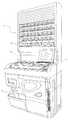
도 1은 본 실시 형태에 관한 약제 분포 장치의 사시도이다.
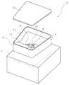
도 2는 도 1의 약제 카세트를 도시하는 사시도이다.
도 3은 도 2의 약제 저류부 및 약제 불출부를 도시하는 사시도이다.
도 4는 도 3으로부터 약제 저류부의 저류 용기를 제거한 상태를 도시하는 사시도이다.
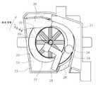
도 5는 도 2의 약제 불출부를 도시하는 사시도이다.
도 6은 도 5의 평면도이다.
도 7은 도 5의 분해 사시도이다.
도 8은 도 5의 정면 단면도이다.
도 9는 다른 실시 형태에 관한 약제 불출부의 개략을 도시하는 단면도이다.1 is a perspective view of a medicine distributing apparatus according to the present embodiment.
Fig. 2 is a perspective view showing the medicine cassette of Fig. 1;
FIG. 3 is a perspective view showing the medicine reservoir and the dispenser of FIG. 2;
Fig. 4 is a perspective view showing a state where the storage container of the medicine storage portion is removed from Fig. 3; Fig.
5 is a perspective view showing the dispenser of FIG. 2;
Fig. 6 is a plan view of Fig. 5. Fig.
7 is an exploded perspective view of Fig.
Fig. 8 is a front sectional view of Fig. 5. Fig.
9 is a cross-sectional view schematically showing the medicine dispensing portion according to another embodiment.
이하, 본 발명에 관한 실시 형태를 첨부 도면에 따라 설명한다. 또한 이하의 설명은 본질적으로 예시에 불과하며, 본 발명, 그 적용물, 또는 그 용도를 제한하는 것을 의도하는 것은 아니다.DESCRIPTION OF THE PREFERRED EMBODIMENTS Hereinafter, embodiments of the present invention will be described with reference to the accompanying drawings. Furthermore, the following description is merely exemplary in nature and is not intended to limit the invention, its application, or uses thereof.
도 1은, 본 실시 형태에 관한 약제 분포 장치의 사시도이다. 이 약제 분포 장치는, 자동 약제 공급부(1), 수동 살포 약제 공급부(2), 약제 분포부(3), 제어 장치(4) 등을 구비한다. 자동 약제 공급부(1)에서는, 폭 방향으로 복수 열, 높이 방향으로 복수 단의 매트릭스형으로 배치된 카세트 장착부(도시되지 않음)에 약제 카세트(5)가 각각 분리 가능하게 장착되어 있다.1 is a perspective view of a medicine distributing apparatus according to the present embodiment. This medicine distributing apparatus includes an automatic medicine supply section 1, a manual spraying
약제 카세트(5)는, 도 2에 도시한 바와 같이, 약제 저류부(6)와 약제 불출부(7)를 구비한다.The
약제 저류부(6)는 저류 용기(8) 내에 보충용 회전체(9)를 배치한 것이다. 저류 용기(8) 내에는 동일한 종류의 약제(10)(정제, 캡슐제 등)가 복수 수용되며, 적절히 약제 불출부(7)에 보급된다.The medicine storage part (6) is arranged in the storage container (8) with the supplementary rotation body (9). A plurality of medicines 10 (tablets, capsules, etc.) of the same kind are accommodated in the
저류 용기(8)는, 도 3에 도시한 바와 같이, 평면에서 보아 대략 사다리꼴형으로 되도록 둘러싸인 주위벽(11)을 갖는다. 주위벽(11)을 구성하는 1개의 측벽 내면으로부터는 비스듬히 하방으로 연장되는 가이드벽(12)이 형성되어 있다. 이 가이드벽(12)을 이용하여 약제(10)를 보충한다. 가이드벽(12)은 보충되는 약제(10)를 원활히 저면측으로 이동시키기 위한 것이며, 저면측에 기세 좋게 충돌하여 손상되는 것을 방지한다. 가이드벽(12)이 형성되는 부분의 하방측에는 보급구(13)가 형성되어 있다. 보급구(13)는 본 발명의 폐쇄부를 구성하는 셔터(14)에 의하여 개폐 가능하게 되어 있다.As shown in Fig. 3, the
셔터(14)는 카세트 장착부로부터 약제 카세트(5)를 분리함으로써 자동으로 폐쇄되는 구성인 것이 바람직하다. 예를 들어 스프링 등으로 셔터(14)을 가압하여 보급구(13)를 폐쇄하고, 카세트 장착부측에 맞닿음부를 설치하고, 약제 카세트(5)를 카세트 장착부에 장착한 상태에서 셔터(14)의 일부가 맞닿음부에 맞닿아 보급구(13)를 개방시키도록 하면 된다.It is preferable that the
저류 용기(8)의 상방 개구부는, 도 2에 도시한 바와 같이, 분리 가능하게 장착되는 덮개(15)로 폐쇄되어 있다. 저류 용기(8)의 저면 중앙 부분에는 개구부(16)가 형성되며, 거기에는 보충용 회전체(9)가 배치되어 있다.As shown in Fig. 2, the upper opening of the
보충용 회전체(9)는, 도 4에 도시한 바와 같이, 원판형이며, 외주 기어(17)를 갖고, 상면에는 회전 중심으로부터 외경 방향을 향하여 복수의 돌조(18)가 뻗어 있다.As shown in Fig. 4, the supplementary
외주 기어(17)에는 제1 기어(19) 및 제2 기어(20)가 순차 교합하며, 제2 기어(20)는 제1 모터(21)의 회전축에 일체화되어 있다. 이것에 의하여, 제1 모터(21)의 구동력이 제2 기어(20), 제1 기어(19)를 통하여 보충용 회전체(9)에 전달된다. 제1 모터(21)는 정역 회전 가능하다. 보충용 회전체(9)가 정 회전하면, 보충된 약제(10)가 보급구(13)를 향하여 반송된다.The
도 4로 되돌아와, 돌조(18)는 회전축으로부터 외경측을 향하여 균등하게 방사상, 상세하게는 회전 방향 상류측을 향하여 서서히 변위되도록 만곡되어 뻗어 있다.Returning to Fig. 4, the
약제 불출부(7)는, 도 5 내지 도 7에 도시한 바와 같이, 지지 용기(22) 내에 보유 지지 부재(23)를 고정하고, 제1 회전체(24), 제2 회전체(25), 높이 규제 부재(26), 폭 규제 부재(27), 가이드 부재(28) 등을 설치한 것이다.5 to 7, the
지지 용기(22)는 주위의 측벽과 저벽으로 구성되며, 보유 지지 부재(23), 높이 규제 부재(26), 폭 규제 부재(27)를 각각 나사 고정할 수 있게 되어 있다. 측벽의 일부가 절결됨으로써 약제(10)의 배출구(29)가 형성되어 있다. 배출구(29)로부터 배출되는 약제(10)는, 도 3에 도시한 바와 같이, 센서(30)에 의하여 검출되어 계수 가능하게 되어 있다. 도 7에 도시한 바와 같이, 저벽에는 상면이 경사진 직사각형 돌기부(31)가 형성되고, 그 중심 부분에는 제1 회전체(24)를 회전 가능하게 지지하는 통부(32)가 형성되어 있다. 직사각형 돌기부(31)의 주위에는, 상기 통부(32)의 축심을 중심으로 하는 원통 형상의 일부가 절제된 상태에서 원호부(33)가 돌출하고 있다. 이 원호부(33)의 내면과, 경사진 제1 회전체(24)의 상면으로 약제(10)의 저류 오목부(34)(도 5 참조)를 구성하고 있다. 원호부(33)의 주위에는 환형부(35)가 형성되어 있다. 환형부(35)에는 제2 회전체(25)가 적재되어 있다. 제2 회전체(25)에는, 저류 오목부(34)의 일부가 절제되어 형성된 연통구(36)를 통하여, 후술하는 구동 기어(46)로부터 제3 모터(45)의 구동력이 전달되도록 되어 있다.The
보유 지지 부재(23)는 지지 용기(22)의 오목부 내에 배치되어 하면측으로부터 나사 고정된다. 보유 지지 부재(23)의 일부는 돌출부(37)로 구성되어 있다. 이 돌출부(37)의 내면은, 제2 회전체(25)의 외주 부분을 둘러싸는 내주면의 일부를 구성한다. 돌출부(37)의 상면에는 가이드 부재(28)를 나사 고정할 수 있게 되어 있다. 돌출부(37)의 일단부면은, 대향하여 배치되는 폭 규제 부재(27)와의 사이에 배출 통로(38)(도 5 참조)를 형성한다.The holding
제1 회전체(24)는 상술한 보충용 회전체(9)와 마찬가지인 원판형이며, 상면, 즉, 원형면에는 회전 중심으로부터 방사상으로 복수의 돌조(39)가 뻗어 있다(여기서는 45° 간격으로 8개 형성되어 있음). 제1 회전체(24)는 그 회전축이 연직 방향에 대하여 경사지도록 배치되고, 상면이 수평면에 대하여 경사져 있다(본 실시 형태에서의 경사 각도는 18°임).The first
제1 회전체(24)의 회전축의 하단부에는, 도 8에 도시한 바와 같이, 종동 기어(40)가 일체화되어 있다. 종동 기어(40)에는, 제2 모터(41)의 회전축에 일체화된 구동 기어(42)가 교합하고 있다. 이것에 의하여, 제2 모터(41)의 구동력이 구동 기어(42) 및 종동 기어(40)를 통하여 제1 회전체(24)에 전달된다.At the lower end of the rotating shaft of the first
제2 회전체(25)는, 도 7에 도시한 바와 같이, 제1 회전체(24)의 외주에 배치되는 환형의 평판이다. 제2 회전체(25)는 그 상면, 즉, 환형면이 수평면 상에 위치하도록 배치되어 있다. 또한 제2 회전체(25)의 하면측에는 통 형상부(43)가 형성되고, 그 외주면에는 종동 기어(44)가 형성되어 있다. 종동 기어(44)에는, 도 8에 도시한 바와 같이, 제3 모터(45)의 회전축에 일체화된 구동 기어(46)가 교합하고 있다. 이것에 의하여, 제3 모터(45)의 구동력이 구동 기어(46) 및 종동 기어(44)를 통하여 제2 회전체(25)에 전달된다.The second
높이 규제 부재(26)는 대략 직육면체 형상이며, 지지 용기(22)의 측벽에 나사 고정됨으로써 그 하면과 제2 회전체(25) 사이에 간극을 형성한다. 이 간극은 나사 고정 위치를 변경하여 약제(10)를 1개만 통과 가능해지도록 조정할 수 있게 되어 있다.The
폭 규제 부재(27)는 만곡면(47)을 갖는다. 폭 규제 부재(27)는 지지 용기(22)의 측벽에 나사 고정되며, 제2 회전체(25)의 외주보다도 내측으로 돌출하도록 배치됨으로써 제2 회전체(25)의 상면의 노출 폭 치수를 규제하여, 제2 회전체(25)의 회전에 의하여 약제(10)를 1개만 반송할 수 있게 되어 있다. 노출 폭 치수는 나사 고정 위치를 변경함으로써 조정할 수 있게 되어 있다.The
가이드 부재(28)는 지지부(48)와 가이드편(49)으로 구성되어 있다. 지지부(48)는 평판을 대략 L자형으로 한 것이며, 일단부측에는 보유 지지 부재(23)에 나사 고정하기 위한 관통 구멍이 형성되어 있다. 지지부(48)의 타 단부측에는 직사각형의 가이드편(49)이, 제1 회전체(24)의 상면에 대하여 비접촉 상태에서 직교하는 방향으로 되도록 고정되어 있다. 가이드편(49)에는 실리콘 고무 등의, 가요성을 갖고 내마모성이 우수한 재료가 사용되고 있다.The
도 6에 도시한 바와 같이, 가이드편(49)은, 지지부(48)의 타 단부측이 연장되는 직경 방향(도 6 중, 2점 쇄선으로 나타냄)에 대하여, 서서히 제1 회전체(24)의 회전 방향 하류측을 향하여 만곡된다. 이것에 의하여, 가이드편(49)에는, 제1 회전체(24)의 외경측으로 팽출된 가이드면이 형성된다. 제1 회전체(24)를 회전시킴으로써 맞닿는 약제(10)로부터 필요 이상의 힘이 작용하면, 적절히 탄성 변형되면서 이 약제(10)를 외경측으로 이동시킬 수 있다.6, the
가이드편(49)의 선단부 위치는, 제2 회전체(25)의 내주연에 합치하고, 제1 회전체(24)의 상면과 제2 회전체(25)의 상면의 단차가 대략 0으로 되는 위치로부터 회전 방향으로 어긋난 위치로 되어 있다{도 6에서는 약제(10)의 가이드편(49)에의 압접 상태는 도시하고 있지 않지만, 가이드편(49)은 약제(10)가 압접함으로써 만곡됨). 이와 같이, 가이드편(49)의 선단부 위치를 설정하고 있으므로, 가이드편(49)이 제2 회전체(25)의 회전 동작의 방해로 되는 일이 없고, 또한 약제(10)를 확실히 제1 회전체(24)로부터 제2 회전체(25) 상으로 이동시킬 수 있다.The tip end position of the
상기 구성의 약제 불출부(7)에서는, 경사진 제1 회전체(24)와 제2 회전체(25)의 단차가 0으로 된 기준 위치로부터 약 40° 내지 약 45° 회전한 위치에 가이드 부재(28)의 가이드편(49)의 선단부가 위치하고 있다. 또한 기준 위치로부터 약 90° 회전한 위치에 높이 규제 부재(26)가 배치되어, 통과 가능한 약제(10)의 높이 치수가 규제되어 있다. 나아가 높이 규제 부재(26)를 넘어, 기준 위치로부터 약 180° 회전한 범위에 폭 규제 부재(27)가 배치되어 있다.In the
제어 장치(4)는, 센서(30)에서의 검출 신호나 도시되지 않은 서버 등으로부터의 처방 데이터 등에 기초하여 제1 모터(21), 제2 모터(41) 및 제3 모터(45)를 구동 제어하여, 이하에 설명하는 불출 처리를 실행한다.The
다음으로, 상기 구성으로 이루어지는 약제 카세트(5)의 동작에 대하여 설명한다. 약제 카세트(5) 내에 수용된 약제(10)를 불출하는 경우, 제1 회전체(24) 및 제2 회전체(25)를 회전시킨다. 이것에 의하여, 제1 회전체(24) 상의 약제(10)가 주위 방향으로 이동하여 가이드 부재(28)의 가이드편(49)에 맞닿는다. 가이드편(49)에 맞닿은 약제(10)는 가이드편(49)을 따라 외경측으로 이동한다. 가이드편(49)을 설치함으로써, 제1 회전체(24)의 회전 속도를 종래에 비하여 느리게 하여, 작용시키는 원심력만으로는 약제(10)를 외경측으로는 이동시킬 수 없는 경우에도, 원활히 이동시키는 것이 가능해진다.Next, the operation of the
그런데 제1 회전체(24)의 외경 치수를 종래에 비하여 대폭 작게 한 경우, 종래와 마찬가지의 회전 속도로 제1 회전체(24)를 회전시키면, 약제(10)에 작용시키는 원심력이 부족하다. 이 때문에 제1 회전체(24)의 회전 속도를 크게 할 필요가 있다. 그러나 제1 회전체(24)의 회전 속도를 빠르게 하면, 종래에 비하여 약제(10)와 제1 회전체(24)의 미끄럼 접촉 속도가 증대되어 약제(10)가 손상되기 쉬운 상황이 발생한다. 본 실시 형태에서는, 가이드 부재(28)를 설치함으로써, 제1 회전체(24)의 회전 속도를 종래보다도 느리게 하여 약제(10)의 손상을 충분히 억제하면서, 확실히 제2 회전체(25) 상으로 이송하는 것이 가능하게 되어 있다. 여기서는, 제1 회전체(24)의 회전 속도를 제2 회전체(25)와 동일하게 하고 있다. 즉, 약제(10)를 확실히 1개씩 불출하는 데 적합한 속도에 맞춘 속도로 하고 있다. 또한 가이드편(49)은 탄성을 갖는 재료로 구성되어 있다. 높이 규제체(26), 폭 규제체(27)의 위치는 배출 대상인 약제의 크기에 따라 조정이 가능하게 되어 있다. 또한 약제가 통과하는 가이드편(49)의 선단부(외경 방향의 단부)와 보유 지지 부재(23)의 내주면의 간격은, 가이드편(49)이 탄성 변형 가능하기 때문에, 배출 대상인 약제의 크기의 차이에 따라 변화된다. 따라서 본 실시 형태의 약제 불출부(7)에 의하면 다양한 치수의 약제를 불출할 수 있다. 반송 대상으로 되는 약제(10)는 크기, 형상, 중량 등, 그 성상이 상이하다. 이 때문에, 가이드편(49)이 강체로 구성되어 있으면, 약제(10)가 가이드편(49)을 따라 이동할 때, 막힘을 발생시키는 일도 있다. 여기서는, 가이드편(49)이 약제(10)의 성상의 차이, 특히 크기의 차이에 따라 변형량을 변화시킴으로써, 보유 지지 부재(23)에 의하여 형성되는 내주면과의 거리를 적절한 값으로 변경한다. 그 결과, 약제(10)의 막힘이 발생하기 전에 형상 복귀되어, 즉, 상태를 적절히 해소하거나 막힘이 발생하지 않도록 하거나 할 수 있게 되어 있다. 또한 복수의 약제가 동시에 가이드편(49)의 선단부와 보유 지지 부재(23)의 내주면 사이를 통과하고자 하면 가이드편(49)이 크게 휘며, 일정 치수 이상 휘면 형상 복귀된다. 그 결과, 가이드편(49)이 복수의 약제를 밀어서 복귀시키거나, 경우에 따라서는 약제를 제1 회전체(24)의 회전 방향 상류측으로 튕겨내거나 한다. 이 때문에, 가이드편(49)의 선단부와 보유 지지 부재(23)의 내주면 사이에서 약제의 막힘이 발생하기 어렵고, 또한 복수의 약제가 동시에 가이드편(49)의 선단부와 보유 지지 부재(23)의 내주면 사이를 통과하는 것을 억제할 수 있다.However, if the outer diameter of the first
외경측으로 이동한 약제(10)는 제1 회전체(24)로부터 제2 회전체(25)로 이송된다. 제2 회전체(25)로 이송된 약제(10)는 제2 회전체(25)의 회전에 의하여, 먼저 높이 규제 부재(26)에 의하여 2단 이상으로 중첩된 약제(10)나, 종 방향으로 배치된 약제(10)가 내측으로 복귀된다. 높이 규제 부재(26)를 통과한 약제(10)는, 폭 규제 부재(27)에 의하여 미리 결정된 폭 치수를 초과하는 것(예를 들어 2열로 나열된 약제 등)이 내측으로 복귀된다.The
이와 같이 하여, 높이 규제 부재(26) 및 폭 규제 부재(27)에 의하여 통과 가능한 영역이 제한됨으로써 통과한 1개의 약제(10)는 배출구(29)로부터 불출된다. 여기서, 불출된 약제(10)가 센서(30)에 의하여 검출되면, 제1 회전체(24) 및 제2 회전체(25)의 회전을 정지시킨다. 이것에 의하여, 확실히 1개의 약제(10)를 불출할 수 있다. 이하, 제1 회전체(24) 및 제2 회전체(25)의 회전을 재개하고, 센서(30)에 의하여 약제(10)가 1개 검출될 때마다 정지시키는 것을 반복하여, 소정 수량의 약제(10)가 불출되면 불출 처리를 종료한다.In this way, the area through which the
이 사이, 약제 불출부(7)의 저류 오목부(34)로부터 불출된 약제(10)가 약제 불출부(7)의 특정 위치{예를 들어 제2 회전체(25) 상}에 위치하는지의 여부를, 도시되지 않은 센서에 의하여 검출하여, 특정 위치에 약제가 위치해 있지 않다고 판단함으로써 보충용 회전체(9)를 회전시킨다. 그리고 특정 위치에 약제가 위치한 것이 검출됨으로써, 보충용 회전체(9)의 회전을 정지시키도록 하면 된다. 단, 불출하는 약제(10)의 수량이 미리 설정한 소정 수량에 도달함으로써, 약제(10)를 보충할 필요가 있다고 판단하여 보충용 회전체(9)를 회전시키도록 해도 된다. 보충용 회전체(9)의 회전은, 실험 등에서 구한 시간과 보충 가능한 약제(10)의 수량의 관계에 기초하여 소정 시간 행하도록 하면 된다. 요컨대 약제 불출부(7)에서의 약제(10)의 보충 상황에 기초하여 약제를 공급하도록 하면 된다(전자에서는 특정 위치의 약제(10)의 유무로부터 보충 상황이 불출 가능한 것인지의 여부를 추측하도록 하고 있고, 후자에서는 실제의 불출량으로부터 약제 불출부(7)에서의 약제(10)의 수량을 연산하여 보충 상황을 정확히 특정하도록 하고 있음).It is determined whether the
실시예Example
여기서 종래의 약제 카세트(5)(비교예 1, 2)와, 상기 실시 형태에 관한 약제 카세트(5)이며 가이드 부재(28)를 설치하지 않는 것(비교예 3)과, 설치한 것(실시예 1)이, 약제(10)를 적절히 불출할 수 있는지의 여부에 대하여 비교 실험을 행하였다. 비교예 1에서는 제1 회전체(24)의 외경 치수를 160㎜, 제1 회전체(24)의 수평면에 대한 경사 각도를 13°로 하였다. 비교예 2에서는 제1 회전체(24)의 외경 치수를 140㎜, 제1 회전체(24)의 수평면에 대한 경사 각도를 18°로 하였다. 비교예 3 및 실시예 1에서는 제1 회전체(24)의 외경 치수를 40㎜, 제1 회전체(24)의 수평면에 대한 경사 각도를 13°로 하였다. 표 1에, 이들 조건에서 직경 10㎜의 정제를 불출하도록 하였다.Here, it is assumed that the conventional medicine cassette 5 (Comparative Examples 1 and 2), the

비교 실험의 결과, 표 1에 나타낸 바와 같이, 비교예 1에서는 정제를 제2 회전체측으로 이송시키는 데 필요한 제1 회전체(24)의 회전 속도의 최솟값은 110rpm, 비교예 2에서는 157rpm, 비교예 3에서는 224rpm이었다. 이에 대하여, 실시예 1에서는 7rpm으로 이송할 수 있었다.As a result of the comparative experiment, as shown in Table 1, in Comparative Example 1, the minimum value of the rotational speed of the first
약제(10)의 불출을 1개씩 확실히 행하는 데 적합한 제2 회전체(25)의 회전 속도는 7 내지 14rpm이다. 따라서 제1 회전체(24)의 회전 속도는, 그 불출 동작의 방해로 되지 않도록 마찬가지의 속도(예를 들어 동일한 속도)로 회전시키면 된다.The rotation speed of the second
이와 같이, 가이드 부재(28)를 설치함으로써, 제1 회전체(24)의 회전 속도를 제2 회전체(25)와 동일한 정도까지 느리게 하더라도, 약제(10)를 확실히 제2 회전체(25) 상으로 이송시킬 수 있다. 따라서 약제(10)가 제1 회전체(24)로부터 받는 충격력을 경감하여 손상에 이르는 것을 방지하는 것이 가능해진다. 또한 제1 회전체(24) 및 제2 회전체(25)를, 약제(10)가 1개 불출될 때마다 정지시키도록 하고 있다. 따라서 약제(10)의 주위 방향의 이동 속도가 커져, 잘못하여 필요 이상의 약제(10)가 불출되는 일도 없다.By providing the
또한 본 발명은 상기 실시 형태에 기재된 구성에 한정되는 것은 아니며, 다양한 변경이 가능하다.The present invention is not limited to the configuration described in the above embodiments, and various modifications are possible.
예를 들어 상기 실시 형태에서는 제1 회전체(24)와 제2 회전체(25)를 각각 별도의 모터에 의하여 회전시키도록 했지만, 동일한 모터에 의하여 회전시키는 것도 가능하다. 예를 들어 도 9에 도시한 바와 같이, 수평면에 대하여 경사진 제1 회전체(24)의 회전축(24a)에 평 기어(24b)를 일체화한다. 평 기어(24b)에는, 회전축(50)의 일단부측에 일체화된 평 기어(50a)를 교합시킨다. 회전축(50)의 타 단부측에 일체화된 베벨 기어(50b)에는, 모터(51)의 회전축(51a)에 일체화된 베벨 기어(51b)를 교합시킨다. 제2 회전체(25)의 종동 기어(44)에, 회전축(52)의 일단부측에 일체화된 평 기어(52a)를 교합시킨다. 회전축(52)의 타 단부측에 일체화된 평 기어(52b)에, 모터(51)의 회전축(51a)에 일체화된 평 기어(51c)를 교합시킨다. 이것에 의하여, 모터(51)을 구동하면, 상기 각 기어를 통하여 각각 제1 회전체(24)와 제2 회전체(25)가 동기하여 회전한다.For example, in the above embodiment, the first
또한 상기 실시 형태에서는, 카세트 장착부로부터 약제 카세트(5)를 분리한 때 셔터(14)로 보급구(13)를 폐쇄하도록 했지만, 약제 카세트(5)로부터 약제 불출부(7)를 분리 가능한 구성으로 하고, 이 약제 불출부(7)를 분리한 때 셔터(14)로 보급구(13)를 폐쇄하도록 해도 된다.In the above embodiment, the
1: 자동 약제 공급부
2: 수동 살포 약제 공급부
3: 약제 분포부
4: 제어 장치
5: 약제 카세트
6: 약제 저류부
7: 약제 불출부
8: 저류 용기
9: 보충용 회전체
10: 약제
11: 주위벽
12: 가이드벽
13: 보급구(공급구)
14: 셔터
15: 덮개
16: 개구부
17: 외주 기어
18: 돌조
19: 제1 기어
20: 제2 기어
21: 제1 모터
22: 지지 용기
23: 보유 지지 부재
24: 제1 회전체
25: 제2 회전체
26: 높이 규제 부재
27: 폭 규제 부재
28: 가이드 부재
29: 배출구
30: 센서
31: 직사각형 돌기부
32: 통부
33: 원호부
34: 저류 오목부
35: 환형부
36: 연통구
37: 돌출부
38: 배출 통로
39: 돌조
40: 종동 기어
41: 제2 모터
42: 구동 기어
43: 통 형상부
44: 종동 기어
45: 제3 모터
46: 구동 기어
47: 만곡면
48: 지지부
49: 가이드편
50: 회전축
51: 모터(구동 수단)
52: 회전축1: Automatic pharmaceutical supply unit
2: manual spraying drug supply unit
3: drug distribution part
4: Control device
5: Pharmaceutical cassette
6:
7:
8: Storage container
9: Replacement swivel full
10: Pharmaceutical
11: surrounding wall
12: guide wall
13: Supply (supply)
14: Shutter
15: Cover
16: opening
17: Outer gear
18: Bump
19: First gear
20: Second gear
21: First motor
22: Support container
23: Holding member
24: 1st whole
25: 2nd whole
26: height regulating member
27:
28: Guide member
29: Outlet
30: Sensor
31: Rectangular projection
32:
33:
34: Retention recess
35: annular part
36:
37:
38: discharge passage
39: Bump
40: driven gear
41: second motor
42: drive gear
43:
44:
45: Third motor
46: drive gear
47: curved face
48: Support
49: Guide
50:
51: motor (driving means)
52:
Claims (8)
Translated fromKorean상기 가이드 부재는, 적어도 상기 약제가 맞닿는 가이드면을 포함하는 부위가, 상기 약제의 크기에 따라 제2 회전체와의 위치 관계를 변화시키도록 탄성 변형 가능한 것을 특징으로 하는, 약제 카세트.The method according to claim 1,
Wherein the guide member is elastically deformable such that a portion including at least a guide surface to which the medicine abuts is changed in positional relationship with the second rotator depending on the size of the medicament.
상기 제1 회전체는 약제를 원심력만에 의해서는 외주측으로 이동시킬 수 없지만, 가이드 부재를 따라 외주측으로 이동 가능해지는 속도로 회전하도록 한 것을 특징으로 하는, 약제 카세트.3. The method according to claim 1 or 2,
Characterized in that the first rotating body can not move the medicine to the outer circumferential side only by the centrifugal force but rotates at a speed at which it can move to the outer circumferential side along the guide member.
상기 제1 회전체와 상기 제2 회전체를 동일한 구동 수단에 의하여 회전시키는 것을 특징으로 하는, 약제 카세트.4. The method according to any one of claims 1 to 3,
Wherein the first rotating body and the second rotating body are rotated by the same driving means.
상기 제1 회전체 및 상기 제2 회전체는 1개의 약제가 불출될 때마다 정지되도록 한 것을 특징으로 하는, 약제 카세트.5. The method according to any one of claims 1 to 4,
Wherein the first rotating body and the second rotating body are stopped each time one medicine is dispensed.
상기 약제 불출부에 약제를 공급하기 위한 약제 공급부를 구비하고, 상기 약제 공급부는 상기 약제 불출부에서의 약제의 보충 상황에 기초하여 약제를 공급 가능한 것을 특징으로 하는, 약제 카세트.6. The method according to any one of claims 1 to 5,
And a medicament supply unit for supplying medicines to the medicament dispenser, wherein the medicament dispenser is capable of supplying medicines based on the replenishment condition of the medicines in the medicament dispenser.
상기 약제 공급부는 상기 약제 불출부로부터 분리 가능하고, 상기 약제 불출부에 약제를 공급하기 위한 공급구와, 상기 약제 공급부로부터 상기 약제 불출부를 분리한 때, 상기 공급구를 폐쇄하는 폐쇄부를 구비한 것을 특징으로 하는, 약제 카세트.The method according to claim 6,
The medicine supply portion is separable from the medicine dispensing portion and includes a supply port for supplying the medicine to the medicine dispensing portion and a closing portion for closing the supply port when the medicine dispensing portion is separated from the medicine supply portion . ≪ / RTI >
카세트 장착부에 착탈 가능하고, 상기 카세트 장착부로부터 분리한 때, 상기 폐쇄부가 상기 약제 불출부의 공급구를 폐쇄하는 것을 특징으로 하는, 약제 카세트.8. The method of claim 7,
Wherein when the medicine cassette is detached from the cassette mounting portion, the closing portion closes the supply port of the medicine dispensing portion.
Applications Claiming Priority (3)
| Application Number | Priority Date | Filing Date | Title |
|---|---|---|---|
| JP2014150196 | 2014-07-23 | ||
| JPJP-P-2014-150196 | 2014-07-23 | ||
| PCT/JP2015/070750WO2016013553A1 (en) | 2014-07-23 | 2015-07-21 | Medicine cassette |
Publications (2)
| Publication Number | Publication Date |
|---|---|
| KR20170034383Atrue KR20170034383A (en) | 2017-03-28 |
| KR102360460B1 KR102360460B1 (en) | 2022-02-10 |
Family
ID=55163077
Family Applications (1)
| Application Number | Title | Priority Date | Filing Date |
|---|---|---|---|
| KR1020177001531AActiveKR102360460B1 (en) | 2014-07-23 | 2015-07-21 | Medicine cassette |
Country Status (6)
| Country | Link |
|---|---|
| US (1) | US9877896B2 (en) |
| EP (1) | EP3173060B1 (en) |
| JP (1) | JP5867666B1 (en) |
| KR (1) | KR102360460B1 (en) |
| CN (1) | CN106535859B (en) |
| WO (1) | WO2016013553A1 (en) |
Families Citing this family (18)
| Publication number | Priority date | Publication date | Assignee | Title |
|---|---|---|---|---|
| CA3006492C (en) | 2015-11-30 | 2023-06-27 | Yuyama Mfg. Co., Ltd. | Medicine cassette, medicine dispensing apparatus and medicine packaging apparatus |
| JP6736064B2 (en) | 2017-01-04 | 2020-08-05 | 株式会社トーショー | Drug feeder |
| CN107380943A (en)* | 2017-07-26 | 2017-11-24 | 宜兴新高合金制品有限公司 | A kind of mass spiral vibration conveying device |
| AU2018318480B2 (en)* | 2017-08-15 | 2023-11-23 | Yuyama Mfg. Co., Ltd. | Tablet guide path-adjusting device of tablet cassette |
| KR101880924B1 (en)* | 2017-09-26 | 2018-07-23 | (주)제이브이엠 | Medicine cassette and automatic medicine packing machine therewith |
| CN107898315B (en)* | 2017-11-21 | 2020-09-04 | 宿迁市宿城区人民医院 | Brewing device and method for traditional Chinese medicine conditioning medicinal tea |
| CN108963852B (en)* | 2018-07-23 | 2020-06-02 | 冯航军 | Electric power overhaul tool distribution device capable of manually changing voltage regulation stabilizing piece of elastic element |
| JP7233076B2 (en)* | 2018-09-21 | 2023-03-06 | 株式会社タカゾノ | drug supply device |
| JP7479037B2 (en)* | 2019-02-04 | 2024-05-08 | 株式会社タカゾノ | Drug Delivery Device |
| CN110884777B (en)* | 2019-10-18 | 2021-08-27 | 福建师范大学 | Medicine bottle capable of simply and conveniently distributing medicine |
| JP7337383B2 (en)* | 2020-01-29 | 2023-09-04 | 株式会社トーショー | drug feeder |
| CN111824475B (en)* | 2020-07-17 | 2021-07-23 | 郑州轻工业大学 | A tablet medicine swinging device with adjustable particle size |
| CN113479954B (en)* | 2021-08-10 | 2022-01-25 | 宿迁凯达环保设备制造有限公司 | Sewage treatment device of environmental protection |
| JP7703186B2 (en)* | 2022-03-25 | 2025-07-07 | 株式会社トーショー | Drug feeders and tablet packaging machines |
| KR20250000175A (en)* | 2023-06-26 | 2025-01-03 | 주식회사 카운텍 | Antioxidant inserting apparatus for drug container |
| CN117550235A (en)* | 2023-11-14 | 2024-02-13 | 苏州慧思腾科技有限公司 | Multifunctional counting pill box medicine sorting and sorting device |
| CN117550236A (en)* | 2023-11-14 | 2024-02-13 | 苏州慧思腾科技有限公司 | Multifunctional counting medicine box |
| CN117600111B (en)* | 2023-12-29 | 2024-07-30 | 中山市仙逸堂中药饮片有限公司 | Accurate quality detection equipment and detection method for traditional Chinese medicine decoction pieces |
Citations (7)
| Publication number | Priority date | Publication date | Assignee | Title |
|---|---|---|---|---|
| JPS6451403A (en) | 1987-08-12 | 1989-02-27 | Desoto Inc | Curing process by active energy ray |
| JPH03147616A (en)* | 1989-11-01 | 1991-06-24 | F I T:Kk | Feeder |
| JP2002347921A (en)* | 2001-05-25 | 2002-12-04 | Ntn Corp | Component feeder |
| KR20120067993A (en)* | 2009-08-28 | 2012-06-26 | 가부시키가이샤 유야마 세이사쿠쇼 | Medication payout device, hopper, and manufacturing method therefor |
| WO2013035692A1 (en)* | 2011-09-06 | 2013-03-14 | 株式会社湯山製作所 | Medicine cassette and medicine supply device |
| KR20130118838A (en) | 2013-08-02 | 2013-10-30 | 임도현 | How to adjust the zero point of sight |
| KR20140138187A (en)* | 2012-03-21 | 2014-12-03 | 가부시키가이샤 유야마 세이사쿠쇼 | Drug-supplying device and drug-counting device |
Family Cites Families (6)
| Publication number | Priority date | Publication date | Assignee | Title |
|---|---|---|---|---|
| JP2000203525A (en)* | 1999-01-11 | 2000-07-25 | Dainippon Printing Co Ltd | Tablet feeding hopper |
| JP2008127133A (en)* | 2006-11-17 | 2008-06-05 | Nakamichi:Kk | Part feeder |
| JP3148073U (en)* | 2008-11-16 | 2009-01-29 | 木下精工有限会社 | Parts supply device |
| JP5835227B2 (en)* | 2010-12-09 | 2015-12-24 | 株式会社湯山製作所 | Drug counting device |
| US9155681B2 (en)* | 2011-01-20 | 2015-10-13 | Yuyama Mfg. Co., Ltd. | Medicine feeding device and a medicine counting device using the medicine feeding device |
| CN105764471A (en)* | 2013-10-09 | 2016-07-13 | 株式会社高园科技 | Medicine filling device |
- 2015
- 2015-07-21EPEP15825431.8Apatent/EP3173060B1/enactiveActive
- 2015-07-21USUS15/328,431patent/US9877896B2/enactiveActive
- 2015-07-21JPJP2015548097Apatent/JP5867666B1/enactiveActive
- 2015-07-21WOPCT/JP2015/070750patent/WO2016013553A1/enactiveApplication Filing
- 2015-07-21CNCN201580038136.4Apatent/CN106535859B/enactiveActive
- 2015-07-21KRKR1020177001531Apatent/KR102360460B1/enactiveActive
Patent Citations (8)
| Publication number | Priority date | Publication date | Assignee | Title |
|---|---|---|---|---|
| JPS6451403A (en) | 1987-08-12 | 1989-02-27 | Desoto Inc | Curing process by active energy ray |
| JPH03147616A (en)* | 1989-11-01 | 1991-06-24 | F I T:Kk | Feeder |
| JP2002347921A (en)* | 2001-05-25 | 2002-12-04 | Ntn Corp | Component feeder |
| KR20120067993A (en)* | 2009-08-28 | 2012-06-26 | 가부시키가이샤 유야마 세이사쿠쇼 | Medication payout device, hopper, and manufacturing method therefor |
| WO2013035692A1 (en)* | 2011-09-06 | 2013-03-14 | 株式会社湯山製作所 | Medicine cassette and medicine supply device |
| KR20140061437A (en)* | 2011-09-06 | 2014-05-21 | 가부시키가이샤 유야마 세이사쿠쇼 | Medicine cassette and medicine supply device |
| KR20140138187A (en)* | 2012-03-21 | 2014-12-03 | 가부시키가이샤 유야마 세이사쿠쇼 | Drug-supplying device and drug-counting device |
| KR20130118838A (en) | 2013-08-02 | 2013-10-30 | 임도현 | How to adjust the zero point of sight |
Also Published As
| Publication number | Publication date |
|---|---|
| JPWO2016013553A1 (en) | 2017-04-27 |
| KR102360460B1 (en) | 2022-02-10 |
| EP3173060B1 (en) | 2019-06-12 |
| US9877896B2 (en) | 2018-01-30 |
| JP5867666B1 (en) | 2016-02-24 |
| CN106535859A (en) | 2017-03-22 |
| US20170216150A1 (en) | 2017-08-03 |
| EP3173060A1 (en) | 2017-05-31 |
| WO2016013553A1 (en) | 2016-01-28 |
| EP3173060A4 (en) | 2018-03-21 |
| CN106535859B (en) | 2019-06-14 |
Similar Documents
| Publication | Publication Date | Title |
|---|---|---|
| KR20170034383A (en) | Medicine cassette | |
| US9582956B2 (en) | Tablet feeder | |
| KR101820799B1 (en) | Drug dispenser and drug counter | |
| US9233789B2 (en) | Medicine-supplying device and medicine-counting device | |
| KR100729477B1 (en) | Tablet feeder | |
| RU2700922C2 (en) | Container for drug delivery in automatic dispenser of medicinal agents | |
| CN115942927A (en) | Storage containers for storage and distribution stations | |
| US20130320033A1 (en) | Article dispensing | |
| JP2023052649A (en) | Medicine packaging apparatus | |
| JP2024174016A (en) | Drug Delivery Device | |
| US20210161768A1 (en) | Storage container for a storage and dispensing station for pharmaceuticals | |
| US9481482B2 (en) | Article dispensing | |
| JP7081799B2 (en) | Tablet supply device and drug delivery device | |
| KR101107664B1 (en) | Tablet Dispenser Of Pharmaceutical Automatic Packing Machine | |
| JP4852114B2 (en) | Powder distribution device and packing machine | |
| JP2020069354A (en) | Tablet cassette | |
| US10329098B2 (en) | Automated vial hopper and feeder assembly | |
| JP2005258556A (en) | Capsule discharging device | |
| JP2025126278A (en) | Drug supply device | |
| JP2025019464A (en) | Fixed quantity supply device | |
| HK40004122B (en) | Medicine feeding canister for in an automated medicine dispensing device |
Legal Events
| Date | Code | Title | Description |
|---|---|---|---|
| PA0105 | International application | Patent event date:20170118 Patent event code:PA01051R01D Comment text:International Patent Application | |
| PG1501 | Laying open of application | ||
| PA0201 | Request for examination | Patent event code:PA02012R01D Patent event date:20200520 Comment text:Request for Examination of Application | |
| E701 | Decision to grant or registration of patent right | ||
| PE0701 | Decision of registration | Patent event code:PE07011S01D Comment text:Decision to Grant Registration Patent event date:20220120 | |
| PR0701 | Registration of establishment | Comment text:Registration of Establishment Patent event date:20220204 Patent event code:PR07011E01D | |
| PR1002 | Payment of registration fee | Payment date:20220207 End annual number:3 Start annual number:1 | |
| PG1601 | Publication of registration | ||
| PR1001 | Payment of annual fee | Payment date:20250124 Start annual number:4 End annual number:4 |