KR20170029157A - Flowrate Control System of Cooling Water - Google Patents
Flowrate Control System of Cooling WaterDownload PDFInfo
- Publication number
- KR20170029157A KR20170029157AKR1020150126126AKR20150126126AKR20170029157AKR 20170029157 AKR20170029157 AKR 20170029157AKR 1020150126126 AKR1020150126126 AKR 1020150126126AKR 20150126126 AKR20150126126 AKR 20150126126AKR 20170029157 AKR20170029157 AKR 20170029157A
- Authority
- KR
- South Korea
- Prior art keywords
- cooling water
- flow rate
- flow
- pipe
- bru
- Prior art date
- Legal status (The legal status is an assumption and is not a legal conclusion. Google has not performed a legal analysis and makes no representation as to the accuracy of the status listed.)
- Withdrawn
Links
- 239000000498cooling waterSubstances0.000titleclaimsabstractdescription140
- 238000001816coolingMethods0.000claimsabstractdescription17
- 238000007599dischargingMethods0.000claimsabstractdescription4
- 238000000034methodMethods0.000claimsdescription8
- 238000007670refiningMethods0.000claimsdescription3
- 239000013535sea waterSubstances0.000description8
- 238000002955isolationMethods0.000description7
- 230000001105regulatory effectEffects0.000description6
- 230000001276controlling effectEffects0.000description4
- 238000001914filtrationMethods0.000description4
- 239000002826coolantSubstances0.000description3
- 239000000470constituentSubstances0.000description2
- 238000010586diagramMethods0.000description2
- 238000005553drillingMethods0.000description2
- 238000011010flushing procedureMethods0.000description2
- 238000012544monitoring processMethods0.000description2
- 239000000126substanceSubstances0.000description2
- 238000005406washingMethods0.000description2
- 230000000694effectsEffects0.000description1
- 239000012530fluidSubstances0.000description1
- 238000012423maintenanceMethods0.000description1
- 238000005259measurementMethods0.000description1
- XLYOFNOQVPJJNP-UHFFFAOYSA-NwaterSubstancesOXLYOFNOQVPJJNP-UHFFFAOYSA-N0.000description1
Images

Classifications
- B—PERFORMING OPERATIONS; TRANSPORTING
- B63—SHIPS OR OTHER WATERBORNE VESSELS; RELATED EQUIPMENT
- B63B—SHIPS OR OTHER WATERBORNE VESSELS; EQUIPMENT FOR SHIPPING
- B63B35/00—Vessels or similar floating structures specially adapted for specific purposes and not otherwise provided for
- B63B35/44—Floating buildings, stores, drilling platforms, or workshops, e.g. carrying water-oil separating devices
- B63B35/4413—Floating drilling platforms, e.g. carrying water-oil separating devices
- B—PERFORMING OPERATIONS; TRANSPORTING
- B63—SHIPS OR OTHER WATERBORNE VESSELS; RELATED EQUIPMENT
- B63B—SHIPS OR OTHER WATERBORNE VESSELS; EQUIPMENT FOR SHIPPING
- B63B13/00—Conduits for emptying or ballasting; Self-bailing equipment; Scuppers
- B—PERFORMING OPERATIONS; TRANSPORTING
- B63—SHIPS OR OTHER WATERBORNE VESSELS; RELATED EQUIPMENT
- B63B—SHIPS OR OTHER WATERBORNE VESSELS; EQUIPMENT FOR SHIPPING
- B63B27/00—Arrangement of ship-based loading or unloading equipment for cargo or passengers
- B63B27/16—Arrangement of ship-based loading or unloading equipment for cargo or passengers of lifts or hoists
- B—PERFORMING OPERATIONS; TRANSPORTING
- B66—HOISTING; LIFTING; HAULING
- B66D—CAPSTANS; WINCHES; TACKLES, e.g. PULLEY BLOCKS; HOISTS
- B66D5/00—Braking or detent devices characterised by application to lifting or hoisting gear, e.g. for controlling the lowering of loads
- B66D5/02—Crane, lift hoist, or winch brakes operating on drums, barrels, or ropes
- B66D5/023—Cooling of brakes
- E—FIXED CONSTRUCTIONS
- E21—EARTH OR ROCK DRILLING; MINING
- E21B—EARTH OR ROCK DRILLING; OBTAINING OIL, GAS, WATER, SOLUBLE OR MELTABLE MATERIALS OR A SLURRY OF MINERALS FROM WELLS
- E21B19/00—Handling rods, casings, tubes or the like outside the borehole, e.g. in the derrick; Apparatus for feeding the rods or cables
- E21B19/02—Rod or cable suspensions
Landscapes
- Engineering & Computer Science (AREA)
- Mechanical Engineering (AREA)
- Chemical & Material Sciences (AREA)
- Combustion & Propulsion (AREA)
- Ocean & Marine Engineering (AREA)
- Life Sciences & Earth Sciences (AREA)
- Mining & Mineral Resources (AREA)
- Geology (AREA)
- Structural Engineering (AREA)
- Physics & Mathematics (AREA)
- Environmental & Geological Engineering (AREA)
- Fluid Mechanics (AREA)
- Civil Engineering (AREA)
- Architecture (AREA)
- General Life Sciences & Earth Sciences (AREA)
- Geochemistry & Mineralogy (AREA)
- Flow Control (AREA)
Abstract
Translated fromKoreanDescription
Translated fromKorean본 발명은 냉각수 유량 제어 시스템에 관한 것으로서, 더욱 상세하게는 플로우 미터 및 유량조절밸브를 활용하여 유입되는 냉각수의 유량이 일정하게 공급되도록 함으로써 냉각기능을 충분히 발휘할 수 있도록 한 것이다.The present invention relates to a cooling water flow rate control system, and more particularly, to a cooling water flow rate control system using a flow meter and a flow rate control valve so that the flow rate of the cooling water is constantly supplied.
일반적으로, 해저의 지하에 존재하는 석유나 가스 등을 시추할 수 있도록 각종 시추장비를 갖춘 리그선 또는 드릴십과 같은 선박의 중심부에는 문풀(moonpool)이 형성되고, 이러한 문풀을 통해 해저의 지하에 존재하는 석유나 가스 등을 시추하기 위한 라이저(riser) 또는 드릴 파이프(drill pipe)가 상하로 이동될 수 있도록 설치된다.In general, a moonpool is formed at the center of a ship such as a rig or a drill ship equipped with various drilling equipment to drill oil and gas existing in the underground, A riser or a drill pipe for drilling oil or gas is installed so that it can be moved up and down.
여기서, 상기 라이저의 하중을 지탱하고, 상하 운동을 조작하는 호이스팅 장치(드로웍스(drawworks))가 설치되어 있다.Here, a hoisting device (drawworks) for supporting the load of the riser and operating the up and down movements is provided.
이러한 호이스팅 장치는 제동 동작을 위해서 발생된 전기 에너지를 열 에너지로 변환시켜서 소거되도록 하는 브레이킹 리지스터 유닛(Braking Resistor Unit)(이하 "BRU"라 함)이 갖추어진다.Such a hoisting apparatus is equipped with a braking resistor unit (hereinafter referred to as "BRU") which converts electrical energy generated for braking operation into thermal energy to be erased.
이때, 상기 BRU로부터 발생된 열 에너지를 감쇄시키기 위해서 냉각수를 이용하여 BRU를 냉각시키도록 하는데, 냉각수로는 통상적으로 해수가 이용되고, 종래에는 압력 조절밸브를 이용하여 유입되는 냉각수인 냉각수의 유량을 조절하도록 하였다.At this time, the BRU is cooled using cooling water to attenuate the thermal energy generated from the BRU. In general, seawater is used as the cooling water, and conventionally, the flow rate of the cooling water, which is the cooling water flowing using the pressure control valve, Respectively.
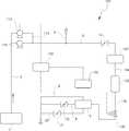
보다 구체적으로 설명하면, 종래에는 도 1에 도시된 바와 같이, 씨체스트(1)(sea chest)를 통해 펌프(2)의 가동으로 냉각수인 냉각수가 유입되어서 BRU(3)를 거쳐서 선박의 외부로 배출되는데, 씨체스트(1)로부터 펌프(2)에 의해 냉각수가 유입되는 유입배관(4)이 형성되고, 펌프(2)로부터 BRU(3)로 냉각수가 이동하는 이동배관(5)과, BRU(3)를 거친 냉각수가 다시 바다로 배출되는 배출배관(6)이 형성된다.More specifically, conventionally, as shown in FIG. 1, cooling water, which is cooling water, is introduced into the ship through the sea chest by the operation of the
이때, 상기 BRU(3)를 냉각수가 통과하는 이동배관(5)상에는 압력조절밸브(10)와 아이소레이션(isolation) 밸브(12)가 각각 갖추어지고, 아이소레이션 밸브(12)와 BRU(3)의 사이에는 압력계(14)가 구비된다.At this time, a
또한, 상기 배출배관(6)상에는 아이소레이션 밸브(16)가 포함되고, BRU(3)에는 냉각수가 과유량으로 공급되는 것을 방지하기 위한 오버플로우 배관(18)과, BRU(3)의 유지,관리를 위해 냉각수인 해수를 드레인시키는 드레인 배관(20)이 각각 연결된다.An
상기 드레인 배관(20)상에도 아이소레이션 밸브(21)가 갖추어진다.An
또한, 상기 이동배관(5)상에는 다른 소비처, 예를 들어 일종의 저장탱크로서 냉각수를 충전하는 머드 피트(mud pit), 데크 워싱 배관(deck washing line), 플러싱 배관(flushing line), 헐 델러지 시스템(hull deluge system) 등으로 냉각수가 공급되도록 하는 공급배관(8)이 분기되어 형성된다.On the moving
따라서, BRU(3)를 냉각시키기 위한 종래의 냉각 시스템은, 기본적으로 펌프(2)의 가동으로 씨체스트(1)로부터 냉각수가 유입되어 유입배관(4)을 거쳐서 이동배관(5)을 통해 BRU(3)를 소정의 압력을 가지고 통과하여 BRU(3)의 냉각이 이루어지도록 한다.Therefore, in the conventional cooling system for cooling the
상기 BRU(3)의 내부에는 발열부품이 냉각되도록 발열부품이 내장되는 냉각탱크(도시되지 않음)가 복수,마련되어 있어, 냉각수가 유입되어 일정 수위가 넘으면 배출배관(6)을 통해 배출되는 구조로서, BRU(3)의 냉각효과를 제대로 발휘하기 위해서는 항상 일정한 유량의 냉각수가 공급되어야 하는데, 이러한 일정 유량의 냉각수 공급을 위해 종래에는 압력조절밸브(10)(특히 자립형(self contained))를 통해 제어하였다.A plurality of cooling tanks (not shown) each having a heat generating component therein are installed in the
상기 압력조절밸브(10)(자립형)는 통과하는 냉각수의 압력을 감지하여 자체적으로 항상 일정한 압력이 유지되도록 조절하기는 하지만, 냉각수의 압력이 작은 경우에는 냉각수의 유량도 작아지고, 냉각수의 압력이 커지면 냉각수의 유량도 증가하므로, 압력계(14)를 통해 통과하는 냉각수의 압력이 일정하게 유지되고 있는지 여부를 작업자가 확인해야 하고, 씨체스트(1)를 통해 유입되는 냉각수인 해수의 유입 유량의 압력이 일정하지 않아서 압력조절밸브(10)를 통과하는 냉각수의 압력 조절만으로 정확한 정유량을 확보하기 어려운 문제점이 있었다.The pressure regulating valve 10 (self-standing type) senses the pressure of the cooling water passing therethrough and adjusts itself so that a constant pressure is always maintained. However, when the pressure of the cooling water is small, the flow rate of the cooling water also becomes small, The operator must confirm whether or not the pressure of the cooling water passing through the
다시 말해서, 이동배관(5)으로부터 분기된 공급배관(8)을 통해 다른 소비처로 냉각수가 공급되어 사용될 수 있는데, 다른 소비처로 항상 냉각수를 사용하는 것이 아니고, 간헐적으로 사용되기 때문에, 이동배관(5)을 흐르는 냉각수의 유동 압력이 수시로 변동되므로, 압력조절밸브(10)를 통해 수시로 변동되는 압력을 조절하여 냉각수의 유량조절이 이루어지도록 하더라도, 작업자가 압력계를 직접 확인하면서 호이스팅 시스템 운전을 해야 하는 불편이 수반되고, 냉각수의 압력조절만으로 BRU(3)에 공급되는 냉각수의 정확한 유량조절이 어려웠다.In other words, the cooling water can be supplied to the other consuming place through the
또한, 실제로 설정된 냉각수의 유입 압력이 냉각수의 정유량을 유지하고 있는지 여부를 확인할 수 있는 방법은, 단순히 BRU(3)의 내부에 설치되는 온도 알람의 작동에 의해 BRU(3)의 온도가 적절한 온도로 유지되고 있는지 여부를 확인할 수 밖에 없다.A method of confirming whether or not the inflow pressure of the actually set cooling water maintains the constant flow rate of the cooling water is a method of simply controlling the temperature of the
다시 말해서, BRU(3)내를 정유량의 냉각수가 통과하지 못하면, 발열 부품의 냉각이 제대로 이루어지지 못하여 온도 알람이 작동하게 되고, 그에 따라 설정된 냉각온도를 유지하지 못하고 있다는 것을 알려주는 것이므로, 적절한 온도가 유지되지 못하여 온도 알람이 작동하면, 작업자가 직접 압력조절밸브(10)의 셋팅값을 조절할 수 밖에 없다.In other words, if the cooling water of a constant flow rate can not pass through the
그러나, BRU에 구비된 온도 알람에 의한 알람기능만으로는 정확한 냉각수의 정유량이 공급되는지 여부를 정확하게 확인할 수 있는 것이 아니기 때문에, 이 또한 냉각수의 변동 압력에 대응하여 BRU에 정유량의 냉각수를 공급하는지 여부를 정확하게 확인할 수 없는 문제점이 있다.However, since it is not possible to precisely determine whether or not the correct amount of cooling water to be supplied is supplied only by the alarm function provided by the temperature alarm provided in the BRU, it is also possible to determine whether or not to supply the cooling water of the constant flow rate to the BRU corresponding to the fluctuation pressure of the cooling water There is a problem that can not be confirmed accurately.
다시 말해서, 종래에는 압력조절밸브(10)를 통해 냉각수의 변동 압력 발생에 대응하여 냉각수의 압력을 조절하여 흐르는 유체인 냉각수의 유량이 일정하게 유지되도록 하는 것이지만, 이러한 압력조절밸브(10) 및 압력계(14)에 의한 냉각수의 압력조절만으로 냉각수의 정유량이 유지되고 있는지 여부를 정확하게 확인할 수 없다는 문제점이 있는 것이다.In other words, conventionally, the flow rate of the cooling water, which is a flowing fluid, is kept constant by adjusting the pressure of the cooling water in response to the occurrence of the fluctuating pressure of the cooling water through the
또한, 종래에는 이물질이 포함되어 있는 냉각수가 BRU(3)를 통과하여 배출되는 과정에서, 이물질을 효과적으로 여과할 수 있는 필터링 수단이 제대로 강구되지 못하여 냉각수가 통과하는 배관 내부에 잔존하게 되는 경우, 냉각수의 정유량을 유지하는데 악영향을 미칠 수 있다.When the cooling water containing foreign substances is discharged through the
이에 본 발명은 상기와 같은 종래의 문제점을 해결하기 위해 발명된 것으로서, 본 발명이 해결하고자 하는 과제는, 플로우미터 및 유량조절밸브를 통해 냉각수의 유량을 용이하면서도 정확하게 조절할 수 있도록 한 냉각수 유량 제어 시스템을 제공하는 것이다.SUMMARY OF THE INVENTION Accordingly, it is an object of the present invention to provide a cooling water flow rate control system and a cooling water flow rate control system, .
상기와 같은 과제를 해결하기 위한 본 발명의 해결 수단은, 씨체스트를 통해 유입되는 냉각수가 이동하는 이동배관상에 갖추어지는 메인 펌프와; 상기 이동배관을 통과하는 냉각수에 의해 냉각이 이루어지도록 하는 BRU(3)와; 상기 BRU를 거친 냉각수가 배출되도록 하는 배출배관과; 상기 이동배관상에 다른 소비처로 냉각수가 공급되도록 분기되어 연결되는 공급배관을 포함하고,According to an aspect of the present invention, there is provided a cooling system for a refrigerator, comprising: a main pump provided on a moving pipe through which a cooling water flowing through a seed chest moves; A BRU (3) for cooling by the cooling water passing through the moving pipe; A discharge pipe for discharging the cooling water passing through the BRU; And a supply pipe branched and connected to supply the cooling water to another consuming place on the moving pipe,
상기 이동배관의 내부를 흘러 BRU를 통과하는 냉각수의 유량을 측정하도록 이동배관상에 갖추어지는 플로우 미터와; 상기 플로우 미터로부터 측정된 냉각수의 유량값에 따라 유량을 조절하도록 이동배관상의 플로우 미터 다음 위치에 구비되는 유량조절밸브와; 상기 플로우 미터로부터 측정된 냉각수의 유량값에 따라 유량조절밸브를 제어하도록 하는 제어장치와; 상기 플로우 미터로부터 측정된 유량값을 제어장치에서 판단하도록 신호를 전송하는 플로우 트랜스미터를 포함하는 것이다.A flow meter provided on the moving pipe to measure the flow rate of the cooling water flowing through the moving pipe and passing through the BRU; A flow rate control valve provided at a position next to the flow meter on the moving pipe to adjust the flow rate according to the flow rate value of the cooling water measured from the flow meter; A control device for controlling the flow rate control valve according to the flow rate value of the cooling water measured from the flow meter; And a flow transmitter for transmitting a signal to the controller to determine a flow rate value measured from the flow meter.
또한, 상기 씨체스트를 통해 유입된 냉각수가 흐르는 유입배관으로부터 분기되어 이동배관과 연결되는 분기배관상에는 보조 펌프가 더 포함되는 것이다.Further, an auxiliary pump is further included on the branch pipe branched from the inflow pipe through which the cooling water flowing through the seed chest flows and connected to the moving pipe.
또한, 상기 이동배관상에 구비되면서 플로우미터의 전단 위치에는 냉각수를 여과시켜서 이물질을 제거하도록 하는 필터가 더 포함되는 것이다,In addition, a filter is provided on the moving pipe to filter foreign substances by filtering the cooling water at a front end position of the flow meter.
또한, 상기 필터와 플로우미터의 사이에 연결되는 연결배관과, 플로우미터와 유량조절밸브 사이에 연결되는 연결배관은 직선형으로 형성되는 구조이다.Further, a connection pipe connected between the filter and the flow meter, and a connection pipe connected between the flow meter and the flow rate control valve are linearly formed.
또한, 상기 제어장치는 플로우 미터로부터 측정되는 냉각수의 유량값이 설정 유량값과 다른 경우에는 알람이 울리도록 하는 구조이다.Further, the control device has a structure in which an alarm is sounded when the flow rate value of the cooling water measured from the flow meter is different from the set flow rate value.
또한, 제어장치는 플로우미터에서 측정되는 냉각수의 유량값이 설정된 유량값보다 적은 경우에는 보조펌프가 가동되도록 제어하여 메인펌프와 함께 냉각수의 유입량을 증가시켜서 정유량이 BRU에 공급되도록 하는 구조이다.Further, when the flow rate value of the cooling water measured by the flow meter is smaller than the set flow rate value, the controller controls the auxiliary pump to be operated so that the flow rate of the cooling water is increased together with the main pump so that the refining amount is supplied to the BRU.
이와 같이, 본 발명은 선박의 호이스팅 시스템에 구비되는 BRU의 냉각시, 유입되는 냉각수인 해수의 유량이 일정하게 유지되어 공급될 수 있도록 하기 위해서, 냉각하고자 하는 BRU에 유입되는 냉각수의 압력이 수시로 변동되더라도 냉각수의 플로우 미터를 통해 냉각수의 변동 유량을 정확히 측정하여 플로우 트랜스미터를 통해 제어장치에 정보를 보내서 BRU에 정유량이 정확하게 공급되도록 유량조절밸브를 제어함으로써, BRU에는 냉각수의 변동 압력이 발생하더라도 항상 일정한 유량의 냉각수가 통과될 수 있어, BRU의 냉각효율이 증대되고, 보다 안정적인 호이스팅 시스템 운용이 가능하도록 하는 효과가 있다.As described above, in order to allow the flow rate of the seawater, which is the incoming cooling water, to be constantly supplied when the BRU provided in the hoisting system of the ship is cooled, the pressure of the cooling water flowing into the BRU to be cooled Even if fluctuating pressure of coolant is measured, it is possible to accurately measure the fluctuating flow rate of coolant through coolant flow meter and to send information to control device through flow transmitter to control flow rate control valve so that refined amount can be supplied to BRU accurately. The cooling water of a constant flow rate can be passed, the cooling efficiency of the BRU is increased, and a more stable hoisting system can be operated.
또한, 본 발명은 제어장치에 알람기능을 가지고 있어서, 다른 소비처로로 냉각수를 간헐적으로 이용함에 따라 수시로 변동되는 냉각수 압력에 의해 냉각수의 유량이 제어장치에서 셋팅된 유량값과 비교하여 벗어나는 경우, 알람이 작동하여 알려주도록 함으로써 수시로 정유량의 냉각수가 BRU에 공급되는지 여부를 쉽게 확인할 수 있는 효과가 있다.In addition, the present invention has an alarm function in the control device, so that when the flow rate of the cooling water is out of comparison with the flow rate value set in the control device by the cooling water pressure which varies occasionally as the cooling water is intermittently used for the other consuming destination, So that it is possible to easily confirm whether or not the cooling water of a constant flow rate is supplied to the BRU from time to time.
또한, 본 발명은 BRU에 공급되는 유량이 부족한 경우, 제어장치에서 메인펌프와는 별도로 보조펌프가 자동적으로 가동되도록 제어하여 메인펌프와 동시에 보조펌프를 통해 냉각수인 해수의 유입 유량을 증가시켜서 냉각하고자 하는 냉각수의 유량 부족현상을 해소할 수 있는 효과가 있다.Further, in the present invention, when the flow rate supplied to the BRU is insufficient, the controller controls the auxiliary pump to be automatically operated separately from the main pump, thereby increasing the inflow rate of the seawater as the cooling water through the auxiliary pump at the same time as the main pump, It is possible to eliminate the phenomenon of the shortage of the flow rate of the cooling water.
도 1은 종래의 냉각수 유량 제어 시스템을 설명하기 위한 개략도이다.
도 2는 본 발명의 일 실시 예에 따른 냉각수 유량 제어 시스템을 설명하기 위한 개략도이다.1 is a schematic view for explaining a conventional cooling water flow rate control system.
2 is a schematic diagram for explaining a cooling water flow rate control system according to an embodiment of the present invention.
이하, 본 발명을 실시하기 위한 구체적인 내용을 첨부된 예시도면에 의거 상세하게 설명한다.DETAILED DESCRIPTION OF THE PREFERRED EMBODIMENTS Hereinafter, the present invention will be described in detail with reference to the accompanying drawings.
상기 종래기술과 동일한 구성요소에 대해서는 동일한 부호를 부여하여 설명하고 자세한 설명은 생략하며, 새로운 구성요소에 대해서는 새로운 부호를 부여하여 상세하게 설명한다.The same reference numerals are given to the same constituent elements as those of the conventional art, and a detailed description thereof will be omitted, and new constituent elements will be described in detail with a new code.
도 2는 본 발명의 일 실시 예에 따른 냉각수 유량 제어 시스템을 설명하기 위한 개략도로서, 도면에 도시된 바와 같이, 본 발명의 일 실시 예에 따른 냉각수 유량제어 시스템(100)은, 씨체스트(1)를 통해 냉각수인 냉각수를 유입하는 유입배관(4)과, 이 유입배관(4)과 연결되어 냉각수를 이동시키는 이동배관(5)과, 상기 이동배관(5) 상에 갖추어지는 메인 펌프(110)와, 유입된 냉각수가 이동배관(5)을 통해 이동하여 통과되어 냉각이 이루어지도록 하는 BRU(3)와, 상기 BRU(3)를 거친 냉각수가 배출되도록 하는 배출배관(6)을 포함한다.FIG. 2 is a schematic diagram for explaining a cooling water flow rate control system according to an embodiment of the present invention. As shown in the drawing, a cooling water flow
물론, 상기 메인펌프(110)는 이동배관(5)에 구비되는 것으로 한정되지 않고, 유입배관(4)상에 구비되어도 무방하다.Of course, the
상기 이동배관(5)상에는 다른 소비처(예를 들어 머드 피트(mud pit), 데크 워싱 배관(deck washing line), 플러싱 배관(flushing line), 헐 델러지 시스템(hull deluge system) 등) 로 냉각수가 공급되도록 하는 공급배관(8)이 분기되어 연결되어 있다.On the moving
여기서, 본 발명의 일 실시 예에 따른 냉각수 유량제어 시스템(100)은, 씨체스트(1)를 통해 유입된 냉각수가 흐르는 유입배관(4)상에는 상기 메인 펌프(110) 외에 유사시에 사용가능하도록 하는 보조 펌프(112)가 더 갖추어진다.Here, the cooling water flow
상기 보조펌프(112)는 유입배관(4)으로부터 분기되어 이동배관(5)과 연결되는 분기배관(114)상에 구비된다.The
또한, 상기 이동배관(5)상에는 냉각수를 여과시키는 필터(120)가 마련되고, 이 필터(120) 다음 위치에는 플로우미터(130)가 구비되며, 상기 플로우미터(130) 다음 위치에는 유량조절밸브(140)가 갖추어진다.A
상기 플로우미터(130)는 플로우 트랜스미터(132)와 접속되어 냉각수의 유량값에 대한 정보를 플로우 트랜스미터(132)에 인식하도록 한다.The
또한, 상기 플로우미터(130) 및 플로우 트랜스미터(132)와 유량조절밸브(140)는 제어장치(150)에 의해 제어되는데, 이러한 제어장치(150)로서는 ICMS(Integrated Control and Monitoring System, 통합제어 및 감시 시스템)로 이루어질 수 있는데, 이러한 ICMS는 제어기능과 알람기능을 포함하는 통합 장치인 것이다.The
상기 BRU(3)에는 종래와 마찬가지로, 유입되는 냉각수가 오버되면 흘러서 배출되도록 함으로써, 냉각수의 과유량이 공급되지 않도록 연결되는 오버플로우 배관(18)과, BRU(3)의 관리를 위해 BRU(3)의 내부 냉각탱크안에 있는 냉각수를 모두 배수시키도록 하는 드레인 배관(20)이 각각 갖추어지고, 이동배관(5)과 배출배관(6) 및 드레인 배관(20)상에는 각각 아이소레이션 밸브(12)(16)(21)가 각각 갖추어진다.An
따라서, 드레인 배관(20)에 형성된 아이소레이션 밸브(21)는 BRU(3)의 유지관리를 위해 BRU(3) 내부에 구비되어서 발열부품을 내장하여 냉각이 이루어지도록 하는 냉각탱크안에 있는 냉각수를 드레인시키는 경우에는 개방하고, 평상시에는 폐쇄하도록 한다.Therefore, the
또한, 본 발명은 정확한 유량 측정과 유량 제어를 위해서, 필터(120)와 플로우 미터(130)의 사이에 연결되는 연결배관(5a)과, 플로우 미터(130)와 유량조절밸브(140) 사이에 연결되는 연결배관(5b)을 직선형으로 형성하여 측정하고자 하는 유로에서의 냉각수 유동이 원활하게 이루어지도록 한다.The present invention also includes a
상기 제어장치(150)에는 설정된 유량값과 대비하여 BRU(3)에 유입되는 냉각수의 유량이 설정치를 벗어나는 경우에 알람이 작동하도록 구성되어 있다.The
다시 말해서, 제어장치(150)는, 플로우 미터(130)를 통해 설정된 유량값 이상 또는 이하로 냉각수의 유량이 측정되는 경우에는, 알람이 작동하여 알려주도록 하는 기능을 가져서, 이러한 알람이 작동하여 울림과 동시에, 유량조절밸브(140)를 제어하여 BRU(3)에 유입되는 냉각수가 정유량이 공급되도록 조절한다.In other words, when the flow rate of the cooling water is measured above or below the flow rate value set through the
또한, 상기 보조펌프(112)는 제어장치(150)에 의해 제어되는데, 유입되는 냉각수의 유량이 제어장치(150)에서 설정된 최소한의 유량값보다 작게 측정되는 경우에, 제어장치(150)에서 알람이 울리면서 보조펌프(112)를 자동적으로 작동시켜서 유입되는 냉각수의 유량을 증가시키도록 제어하는데, 이때 메인펌프(110)도 동시에 가동하여 냉각수의 유입 유량을 증가시키도록 한다.The
물론, 이러한 냉각수의 절대 유입유량이 적게되지 않는 상황에서는 보조펌프(112)는 가동하지 않도록 하여, 메인펌프(110)의 가동만으로 유입배관(4)을 통과하는 냉각수인 해수가 이동배관(5)을 지나서 BRU(3)를 통과하도록 하고, 보조펌프(112)가 구비된 분기배관(114)상으로는 보조펌프(112)가 가동하지 않으므로 폐쇄되어서 이동하지 않고 차단되는 것이다.When the absolute inflow flow rate of the cooling water is not reduced, the
이러한 구성을 가지는 본 발명의 일 실시 예에 따르면, 메인펌프(110)의 가동으로 씨체스트(1)를 통해 냉각수가 유입되어 유입배관(4)을 통과하여 이동배관(5)을 이동하여 BRU(3)를 통과한 다음, 배출배관(6)을 통해 바다로 다시 배출되는데, 이 과정에서 냉각수에 의한 BRU(3)의 냉각이 이루어진다.According to one embodiment of the present invention having such a configuration, when the
여기서, 본 발명은 공급배관(8)을 통해 다른 소비처로 냉각수가 사용되거나 또는 사용되지 않는 상황 즉, 간헐적으로 사용될 때, 유입되어 이동하는 냉각수의 압력이 변동되는데, 이때, 플로우미터(130)에서 냉각수의 유량을 측정하여, 그 정보에 해당하는 전기적인 신호를 플로우 트랜스미터(132)를 통해 제어장치(150)에 전송하여 제공한다.In the present invention, when the cooling water is used or not used in other consuming places through the
그러면, 제어장치(150)에서는 초기 셋팅값을 항상 유지할 수 있도록 유량조절밸브(140)에 전기적 신호를 제공하여 유량조절밸브(140)의 개도를 제어함으로써 냉각수의 유량조절이 이루어지도록 한다.Then, the
다시 말해서, 플로우 미터(130)에서 냉각수의 유량값을 확인하는데, 유입되는 냉각수의 압력이 변동되는 상황이 발생하면, 그에 해당하는 변동 유량값을 플로우 트랜스미터(132)를 통해 제어장치(150)에 전기적인 신호값으로 보내면, 제어장치(150)에서는 냉각수의 유량이 항상 요구되는 값(정유량을 보증하는 값)으로 유지될 수 있도록 제어신호를 유량조절밸브(140)에 전달하여 밸브의 개도를 조절할 수 있도록 함으로써 냉각수의 정유량을 확보하여 BRU(3)에 공급되도록 한다.In other words, when the flow meter value of the cooling water is checked in the
또한, 본 발명은 이동배관(5)상에는 필터(120)가 마련되어 있는데, 플로우 미터(130)의 전단에 위치하며, 이러한 필터(120)로 인해 플로우 미터(130)로 유입되는 이물질에 의해 냉각수 유량의 측정값이 달라질 수 있는 것을 방지할 수 있는 것이다.The present invention is characterized in that the
다시 말해서, 상기 플로우 미터(130)는 특성상 냉각수의 전기 전도성, 유속을 활용하여 유량값을 결정하는데, 상기 플로우 미터(130)로 유입되는 냉각수인 해수에 포함된 이물질에 의해 유량의 측정값이 변동되지 않도록 플로우 미터(130)의 앞쪽 위치(전단위치)에서 필터(120)를 통해 냉각수내의 이물질을 걸러주어서 이물질에 의한 냉각수의 유량이 변동되지 않도록 한다.In other words, the
또한, 본 발명은 정유량의 냉각수가 공급되는지 여부를 수시로 확인하기 위해서, 플로우미터(130)를 통해 얻어진 유량값을 플로우 트랜스미터(132)를 통해 제어장치(150)에 전달할 때, 제어장치(150)에 설정된 유량값을 벗어나는 경우, 제어장치(150)에서 알람이 울림과 동시에 유량조절밸브(140)를 제어하여, 적절한 정유량이 공급되도록 한다.When the flow rate value obtained through the
또한, BRU(3)에 유입되는 냉각수인 해수의 절대유량이 적어지는 경우, 즉, 다른 소비처에서의 냉각수 사용량이 증가되어서 BRU(3)를 통과하는 냉각수의 유량이 적어지게 되는 경우, 이때에는, 제어장치(150)에서 이러한 상황을 인식하여 보조펌프(112)가 가동되도록 함으로써, 메인펌프(110)와 동시에 가동하여 씨체스트(1)를 통해 유입되는 냉각수의 절대 유량을 증가시켜서 BRU(3)에 정유량이 공급되도록 한다.In addition, when the absolute flow rate of the seawater as the cooling water flowing into the
다시 말해서, 메인펌프(110)와 함께 보조펌프(112)가 동시에 가동하여 씨체스트(1)를 통해 유입되는 냉각수가 유입배관(4)을 통해 이동배관(5)으로 이동함과 동시에, 유입배관(4)으로부터 분기되어 이동배관(5)과 연결된 분기배관(114)을 통해서도 이동하여 유량조절밸브(140)를 통과하여 BRU(3)에 공급 되므로, 그 만큼 부족한 유량이 증가되어서 적절한 정유량을 제공할 수 있는 것이다.In other words, the
이상에서는 첨부도면에 도시된 본 발명의 구체적인 실시 예를 상세하게 설명하였으나, 이는 본 발명의 바람직한 형태에 대한 예시에 불과한 것이며, 본 발명의 보호 범위가 이들에 한정되는 것은 아니다. 또한, 이상과 같은 본 발명의 실시 예는 본 발명의 기술적 사상 내에서 당해 분야에 통상의 지식을 가진 자에 의해 다양한 변형 및 균등한 다른 실시가 가능한 것이며, 이러한 변형 및 균등한 다른 실시 예들은 본 발명의 첨부된 특허청구범위에 속한다.While the present invention has been particularly shown and described with reference to exemplary embodiments thereof, it is to be understood that the invention is not limited to the disclosed exemplary embodiments. While the present invention has been particularly shown and described with reference to exemplary embodiments thereof, it is to be understood that the invention is not limited to the disclosed embodiments, but, on the contrary, But fall within the scope of the appended claims.
1 : 씨체스트
2 : 펌프
3 : BRU
4 : 유입배관(inlet line)
5 : 이동배관
6 : 배출배관
7 : 오버로드 배관
8 : 공급배관
10 : 압력조절밸브
12 : 아이소레이션 밸브
14 : 압력계
16 : 이이소레이션 밸브
17 : 아이소레이션 밸브
18 : 오버플로우 배관
20 : 드레인 배관
100 : 냉각수 유량 제어 시스템
110 : 메인 펌프
112 : 보조 펌프
114 : 분기배관
120 : 필터
130 : 플로우미터
132 : 플로우 트랜스미터
140 : 유량조절밸브
150 : 제어장치1: Seed chest
2: Pump
3: BRU
4: Inlet line
5: Movable piping
6: Discharge piping
7: Overload piping
8: Supply piping
10: Pressure regulating valve
12: Isolation valve
14: Manometer
16: Isolation valve
17: Isolation valve
18: Overflow piping
20: drain pipe
100: Cooling water flow control system
110: main pump
112: auxiliary pump
114: branch piping
120: Filter
130: Flow meter
132: Flow transmitter
140: Flow control valve
150: Control device
Claims (6)
Translated fromKorean상기 이동배관을 통과하는 냉각수에 의해 냉각이 이루어지도록 하는 BRU(3)와;
상기 BRU(3)를 거친 냉각수가 배출되도록 하는 배출배관(6)과;
상기 이동배관(5)상에 다른 소비처로 냉각수가 공급되도록 분기되어 연결되는 공급배관(8)을 포함하고,
상기 이동배관(5)의 내부를 흘러 BRU(3)를 통과하는 냉각수의 유량을 측정하도록 이동배관(5)상에 갖추어지는 플로우 미터(130)와;
상기 플로우 미터(130)로부터 측정된 냉각수의 유량값에 따라 유량을 조절하도록 이동배관(5)상의 플로우 미터(130) 다음 위치에 구비되는 유량조절밸브(140)와;
상기 플로우 미터(130)로부터 측정된 냉각수의 유량값에 따라 유량조절밸브(140)를 제어하도록 하는 제어장치(150)와;
상기 플로우 미터(130)로부터 측정된 유량값을 제어장치(150)에서 판단하도록 신호를 전송하는 플로우 트랜스미터(132);
를 포함하는 것을 특징으로 하는 냉각수 유량 제어 시스템.
A main pump 110 provided on a moving pipe 5 through which the cooling water flowing through the seed chest 1 moves;
A BRU (3) for cooling by the cooling water passing through the moving pipe;
A discharge pipe (6) for discharging the cooling water passing through the BRU (3);
And a supply pipe (8) branched and connected to supply the cooling water to another consuming place on the moving pipe (5)
A flow meter (130) provided on the moving pipe (5) to measure the flow rate of the cooling water flowing through the moving pipe (5) and passing through the BRU (3);
A flow control valve 140 provided at a position next to the flow meter 130 on the moving pipe 5 to adjust the flow rate according to the flow rate of the cooling water measured from the flow meter 130;
A controller 150 for controlling the flow rate control valve 140 according to the flow rate of the cooling water measured by the flow meter 130;
A flow transmitter 132 for transmitting a signal to the control device 150 to determine a flow rate value measured by the flow meter 130;
Wherein the cooling water flow rate control system comprises:
상기 씨체스트(1)를 통해 유입된 냉각수가 흐르는 유입배관(4)으로부터 분기되어 이동배관(5)과 연결되는 분기배관(114)상에는 보조 펌프(112)가 더 포함되는 것을 특징으로 하는 냉각수 유량 제어 시스템.
The method according to claim 1,
Further comprising an auxiliary pump (112) on a branch pipe (114) branched from the inflow pipe (4) through which the cooling water flowing through the seed chest (1) flows and connected to the moving pipe (5) Control system.
상기 이동배관(5)상에 구비되면서 플로우미터(130)의 전단 위치에는 냉각수를 여과시켜서 이물질을 제거하도록 하는 필터(120)가 더 포함되는 것을 특징으로 하는 냉각수 유량제어 시스템.
The method according to claim 1,
Further comprising a filter (120) provided on the moving pipe (5) to filter the cooling water at the front end of the flow meter (130) to remove foreign matter.
상기 필터(120)와 플로우미터(130 사이에 연결되는 연결배관(5a)과, 플로우 미터(130)와 유량조절밸브(140) 사이에 연결되는 연결배관(5b)은 직선형으로 형성되는 것을 특징으로 하는 냉각수 유량제어 시스템.
The method of claim 3,
The connection pipe 5a connected between the filter 120 and the flow meter 130 and the connection pipe 5b connected between the flow meter 130 and the flow control valve 140 are formed in a straight line. Cooling water flow control system.
상기 제어장치(150)는 플로우 미터(130)로부터 측정되는 냉각수의 유량값이 설정 유량값과 다른 경우에는 알람이 울리도록 하는 것을 특징으로 하는 냉각수 유량제어 시스템.
The method according to claim 1,
Wherein the control device (150) causes an alarm to sound when the flow rate value of the cooling water measured by the flow meter (130) is different from the set flow rate value.
제어장치(150)는 플로우미터(130)에서 측정되는 냉각수의 유량값이 설정된 유량값보다 적은 경우에는, 보조펌프(112)가 가동되도록 제어하여 메인펌프(110)와 함께 냉각수의 유입량을 증가시켜서 정유량이 BRU(3)에 공급 되도록 하는 것을 특징으로 하는 냉각수 유량제어 시스템.The method of claim 2,
When the flow rate of the cooling water measured by the flow meter 130 is smaller than the set flow rate value, the control device 150 controls the auxiliary pump 112 to be operated to increase the inflow amount of the cooling water together with the main pump 110 So that the refining amount is supplied to the BRU (3).
Priority Applications (1)
| Application Number | Priority Date | Filing Date | Title |
|---|---|---|---|
| KR1020150126126AKR20170029157A (en) | 2015-09-07 | 2015-09-07 | Flowrate Control System of Cooling Water |
Applications Claiming Priority (1)
| Application Number | Priority Date | Filing Date | Title |
|---|---|---|---|
| KR1020150126126AKR20170029157A (en) | 2015-09-07 | 2015-09-07 | Flowrate Control System of Cooling Water |
Publications (1)
| Publication Number | Publication Date |
|---|---|
| KR20170029157Atrue KR20170029157A (en) | 2017-03-15 |
Family
ID=58403228
Family Applications (1)
| Application Number | Title | Priority Date | Filing Date |
|---|---|---|---|
| KR1020150126126AWithdrawnKR20170029157A (en) | 2015-09-07 | 2015-09-07 | Flowrate Control System of Cooling Water |
Country Status (1)
| Country | Link |
|---|---|
| KR (1) | KR20170029157A (en) |
Cited By (1)
| Publication number | Priority date | Publication date | Assignee | Title |
|---|---|---|---|---|
| CN110130297A (en)* | 2019-04-18 | 2019-08-16 | 江苏亨通蓝德海洋工程有限公司 | A kind of two-way punching stake system |
Citations (1)
| Publication number | Priority date | Publication date | Assignee | Title |
|---|---|---|---|---|
| KR20150049812A (en) | 2013-10-31 | 2015-05-08 | 대우조선해양 주식회사 | Cooling water flow control apparatus for system having plural coolers |
- 2015
- 2015-09-07KRKR1020150126126Apatent/KR20170029157A/ennot_activeWithdrawn
Patent Citations (1)
| Publication number | Priority date | Publication date | Assignee | Title |
|---|---|---|---|---|
| KR20150049812A (en) | 2013-10-31 | 2015-05-08 | 대우조선해양 주식회사 | Cooling water flow control apparatus for system having plural coolers |
Cited By (1)
| Publication number | Priority date | Publication date | Assignee | Title |
|---|---|---|---|---|
| CN110130297A (en)* | 2019-04-18 | 2019-08-16 | 江苏亨通蓝德海洋工程有限公司 | A kind of two-way punching stake system |
Similar Documents
| Publication | Publication Date | Title |
|---|---|---|
| US9032994B2 (en) | Fire suppression circulation system | |
| CA2967813A1 (en) | Controlled pressure drilling system with flow measurement and well control | |
| RU2579797C1 (en) | Separate hydraulic unit with oil cooling | |
| KR101099742B1 (en) | Marine cooling system using sea water | |
| GB2450086A (en) | Central heating systems | |
| US10207134B2 (en) | System and method for testing a fire suppression system | |
| KR20170029157A (en) | Flowrate Control System of Cooling Water | |
| CN104633457B (en) | A kind of thermal power station's regulating valve real-time online Cavitation detection early warning system and method | |
| JP6582658B2 (en) | Geothermal sampling method and geothermal sampling system | |
| KR20170117251A (en) | Apparatus for testing of water meter | |
| US8157534B2 (en) | Control device for a power unit | |
| ES2829880T3 (en) | Control system of a facility that uses steam | |
| CN104314799A (en) | Oil pump detecting device | |
| CN113107403B (en) | Drilling fluid overflow early warning monitoring system and early warning monitoring method | |
| KR101501457B1 (en) | Apparatus for breaking siphon effect of reactor pool and control method therefor | |
| KR100932469B1 (en) | Stagnant water circulation system at the end of water supply system | |
| NO332968B1 (en) | Device and method for monitoring deposition in a well installation | |
| JP5475076B2 (en) | Residual chlorine meter with water level change detection function | |
| JP2018184798A (en) | Water leakage detection device | |
| WO2023009053A1 (en) | Seawater cooling system and cooling method | |
| US11560698B2 (en) | State analysis device, state analysis method, and recording medium | |
| CN110088559B (en) | Cooling tower adjusting method and system | |
| KR101733382B1 (en) | Apparatus for blocking air inlet to pipe of primary cooling system at core exit side | |
| WO2013036131A1 (en) | Device for monitoring scale in a well installation | |
| JP2009025150A (en) | Water-cooled IC test equipment |
Legal Events
| Date | Code | Title | Description |
|---|---|---|---|
| PA0109 | Patent application | Patent event code:PA01091R01D Comment text:Patent Application Patent event date:20150907 | |
| PG1501 | Laying open of application | ||
| PN2301 | Change of applicant | Patent event date:20191108 Comment text:Notification of Change of Applicant Patent event code:PN23011R01D | |
| PC1203 | Withdrawal of no request for examination |