KR20170024744A - The high efficiency direct current motor and thereof control method - Google Patents
The high efficiency direct current motor and thereof control methodDownload PDFInfo
- Publication number
- KR20170024744A KR20170024744AKR1020150120135AKR20150120135AKR20170024744AKR 20170024744 AKR20170024744 AKR 20170024744AKR 1020150120135 AKR1020150120135 AKR 1020150120135AKR 20150120135 AKR20150120135 AKR 20150120135AKR 20170024744 AKR20170024744 AKR 20170024744A
- Authority
- KR
- South Korea
- Prior art keywords
- stator
- rotor
- motor
- current
- inner stator
- Prior art date
- Legal status (The legal status is an assumption and is not a legal conclusion. Google has not performed a legal analysis and makes no representation as to the accuracy of the status listed.)
- Ceased
Links
- 238000000034methodMethods0.000titleclaimsabstractdescription14
- 239000004020conductorSubstances0.000claimsabstractdescription17
- 238000001816coolingMethods0.000claimsdescription8
- 230000005855radiationEffects0.000claimsdescription6
- 230000000694effectsEffects0.000claimsdescription3
- 238000002485combustion reactionMethods0.000claims1
- 238000004804windingMethods0.000abstractdescription22
- XEEYBQQBJWHFJM-UHFFFAOYSA-NIronChemical group[Fe]XEEYBQQBJWHFJM-UHFFFAOYSA-N0.000abstractdescription12
- 238000010586diagramMethods0.000description4
- 230000001965increasing effectEffects0.000description4
- RYGMFSIKBFXOCR-UHFFFAOYSA-NCopperChemical compound[Cu]RYGMFSIKBFXOCR-UHFFFAOYSA-N0.000description2
- 238000007796conventional methodMethods0.000description2
- 229910052802copperInorganic materials0.000description2
- 239000010949copperSubstances0.000description2
- 230000004907fluxEffects0.000description2
- 229910052742ironInorganic materials0.000description2
- 230000005540biological transmissionEffects0.000description1
- 239000003990capacitorSubstances0.000description1
- 230000015556catabolic processEffects0.000description1
- 230000007423decreaseEffects0.000description1
- 238000007599dischargingMethods0.000description1
- 230000005684electric fieldEffects0.000description1
- 230000006698inductionEffects0.000description1
- 230000001939inductive effectEffects0.000description1
- 230000007257malfunctionEffects0.000description1
- 238000004519manufacturing processMethods0.000description1
- 230000002035prolonged effectEffects0.000description1
- 229910052761rare earth metalInorganic materials0.000description1
- 150000002910rare earth metalsChemical class0.000description1
- 239000004065semiconductorSubstances0.000description1
Images


Classifications
- H—ELECTRICITY
- H02—GENERATION; CONVERSION OR DISTRIBUTION OF ELECTRIC POWER
- H02K—DYNAMO-ELECTRIC MACHINES
- H02K23/00—DC commutator motors or generators having mechanical commutator; Universal AC/DC commutator motors
- H02K23/66—Structural association with auxiliary electric devices influencing the characteristic of, or controlling, the machine, e.g. with impedances or switches
- H—ELECTRICITY
- H02—GENERATION; CONVERSION OR DISTRIBUTION OF ELECTRIC POWER
- H02K—DYNAMO-ELECTRIC MACHINES
- H02K1/00—Details of the magnetic circuit
- H02K1/06—Details of the magnetic circuit characterised by the shape, form or construction
- H02K1/12—Stationary parts of the magnetic circuit
- H02K1/17—Stator cores with permanent magnets
- H—ELECTRICITY
- H02—GENERATION; CONVERSION OR DISTRIBUTION OF ELECTRIC POWER
- H02K—DYNAMO-ELECTRIC MACHINES
- H02K13/00—Structural associations of current collectors with motors or generators, e.g. brush mounting plates or connections to windings; Disposition of current collectors in motors or generators; Arrangements for improving commutation
- H02K13/003—Structural associations of slip-rings
- H—ELECTRICITY
- H02—GENERATION; CONVERSION OR DISTRIBUTION OF ELECTRIC POWER
- H02K—DYNAMO-ELECTRIC MACHINES
- H02K13/00—Structural associations of current collectors with motors or generators, e.g. brush mounting plates or connections to windings; Disposition of current collectors in motors or generators; Arrangements for improving commutation
- H02K13/10—Arrangements of brushes or commutators specially adapted for improving commutation
- H—ELECTRICITY
- H02—GENERATION; CONVERSION OR DISTRIBUTION OF ELECTRIC POWER
- H02K—DYNAMO-ELECTRIC MACHINES
- H02K16/00—Machines with more than one rotor or stator
- H02K16/04—Machines with one rotor and two stators
Landscapes
- Engineering & Computer Science (AREA)
- Power Engineering (AREA)
- Dc Machiner (AREA)
Abstract
Translated fromKoreanDescription
Translated fromKorean본 발명은 직류전동기에 관한것으로써, 자계를 만드는 원통형의 영구자석이 내측 고정자와 외측 고정자에 배치되고 그사이에 회전자의 도체막대가 놓여져 연속적으로 직류전류를 공급함으로써 회전하는 구조로 회전자(전기자)에 철심이 없으며 권선의 저항값과 인덕턴스 값이 매우 낮아 효율이 높은 것을 특징으로 하는 고효율 직류 전동기 및 그 제어방법에 관한 것이다.
[0001] The present invention relates to a DC motor, and more particularly to a DC motor in which a cylindrical permanent magnet for generating a magnetic field is disposed in an inner stator and an outer stator, and a conductor bar of the rotor is placed thereon, ) Having no iron core and having a very low resistance value and inductance value of the winding, and a high efficiency, and a control method thereof.
정류자식 직류전동기의 경우 정류자에 의해 직류전원이 교류전원으로 변환되어 회전자 코일에 인가되며, 고정자는 보통 영구자석 형태로써 회전자(전기자)가 영구자석(6)의 N극과 S극의 위치에 따라 전원이 선택공급됨으로써 회전하는 원리이다.In the rectifier DC motor, DC power is converted to AC power by the rectifier and applied to the rotor coil. The stator is usually in the form of a permanent magnet, so that the rotor (armature) is positioned at the N pole and S pole of the permanent magnet The power is selectively supplied according to the rotation principle.
본 발명의 경우 종래의 직류 전동기와 다르게 회전자에 있어서 회전자계가 필요없는 특별한 구조로, 회전자계를 만드는 별도의 회로나 정류자가 필요없는 게 특징이다. In the present invention, unlike a conventional direct current motor, the rotor has a special structure that does not require a rotor system, and a separate circuit or commutator for forming a rotor system is not required.
종래의 직류 전동기의 경우 전원의 공급이 직류이지만 실제 회전자(전기자)에 공급되는 전원은 반도체나 정류자를 통해서 교류전원을 가하여 회전자계를 만듦으로써 효율이 낮고 센서등의 부품으로 구조가 복잡하며 가격이 높고 효율이 낮은 단점이 있었다. In the conventional DC motor, although the power supply is DC, the power supplied to the actual rotor (armature) is generated by applying alternating current power through the semiconductor or commutator to make the rotating system, so that the efficiency is low, And there is a disadvantage in that the efficiency is low.
본 발명은 직류전원를 회전자에 그대로 공급함으로써 구조가 단순하고 고장이 적고 효율은 높으며 가격이 낮은 장점이 있다.The present invention is advantageous in that the structure is simple, the breakdown is small, the efficiency is high, and the price is low by supplying DC power directly to the rotor.
일반적으로, 직류전동기는 크게 고정자가 영구자석또는 전기적 계자이며 회전자의 자계를 정류자에 의해 공급해 주는 브러쉬부착 방식(정류자 방식)과 회전자가 영구자석인 형태이고, 고정자의 회전자계에 의해 회전하는 브러쉬리스(BLDC) 방식으로 나눌 수 있다. 2. Description of the Related Art Generally, a direct-current motor includes a brush attachment system (commutator system) in which a stator is a permanent magnet or an electric field and supplies a magnetic field of a rotor by a commutator, and a permanent magnet, (BLDC) method.
브러쉬부착 방식(정류자 방식)의 직류전동기는 고정자와 회전자(전기자)와 정류자와 브러쉬를 기본구조로 구성된다. The DC motor of the brush attachment method (commutator type) is composed of a stator, a rotor (armature), a commutator, and a brush as a basic structure.
고정자란 회전자(전기자 이하 회전자)를 기준으로 대칭구조로 형성된 철심으로서 영구자석이나 소정방향으로 감겨진 계자권선에 의하여 서로 다른 극성을 가지는 전자석을 말한다.A stator is an iron core formed symmetrically with respect to a rotor (armature or less rotor), and refers to an electromagnet having a different polarity by a permanent magnet or a field winding wound in a predetermined direction.
회전자는 철심과 이 철심에 감겨진 권선(코일)으로 이루어지고, 정류자는 상기 회전자의 권선(코일)에 브러쉬를 통하여 전원에서 보내지는 직류를 교류로 바꾸어서 보내는 작용을 한다.The rotor is composed of an iron core and a winding (coil) wound around the iron core. The commutator acts on the coil (coil) of the rotor by converting the direct current sent from the power source to alternating current through the brush.
여기서 회전부분 전체를 회전자(전기자)라고 하며, 브러쉬부착 전동기는 계자권선과 전기자권선의 결선 상태에 따라 타여자 전동기, 분권 전동기, 복권 전동기, 직권 전동기, 가동복권 전동기, 차동복권 전동기등으로 나누어진다.Here, the whole rotating part is referred to as a rotor (armature), and a brush-equipped motor is divided into an electric motor, a decoupling motor, a lottery motor, a direct electric motor, an active lottery electric motor and a differential lottery electric motor according to the connection states of field windings and armature windings Loses.
이것은 각각 성질이 다르며 용도에 따라 선택되어 사용되는데, 계자저항(Rf)의 수치를 가감하여 계자에 흐르는 전류를 조절함으로써 속도를 조절하거나 회전자(전기자)의 인가전압의 크기를 변형하여 속도를 조절한다.These are different in properties and are selected and used depending on the application. By controlling the current flowing through the field by adding or subtracting the value of the field resistance (Rf), the speed can be controlled or the speed can be adjusted by modifying the magnitude of the applied voltage of the rotor do.
브러쉬리스 BLDC(Brushless DC)전동기는 그 이름에서 알 수 있는 바와 같이 DC모터에서 브러쉬 구조를 없애고 정류자의 기능을 전자적으로 수행하는 전동기이다. Brushless DC brushless DC motors, as the name suggests, are the motors that eliminate the brush structure in the DC motor and electronically perform the function of the commutator.
보통 회전자는 영구자석형태이며 영구자석의 위치를 홀센서 등의 전자적 센서로 검출하고, 검출된 신호로 전기각을 판단하여 고정자 권선에 전류를 흘려서 토크를 발생시키는 원리이다.Generally, the rotor is a permanent magnet type, and the position of the permanent magnet is detected by an electronic sensor such as a hall sensor, and an electric angle is determined by the detected signal. Current is supplied to the stator winding to generate torque.
회전자에 계자(영구자석), 고정자에 전기자 권선을 설치하고 센서(홀센서, Photo Diode)를 이용하여 권선의 전류방향을 결정함으로써 브러쉬형과 같은 특성을 갖도록 한 것이다.(Permanent magnet) in the rotor, an armature winding in the stator and a current direction of the winding using a sensor (Hall sensor, Photo Diode) to have the same characteristics as the brush type.
일반적으로 전류의 방향전환은 3상 또는 4상 인버터(Inverter)을 이용하고 있고 최근 센서의 신뢰도가 높아지면서 매우 여러 형태의 개발이 이루어지고 있다.Generally, three or four-phase inverters are used to change the direction of current. In recent years, various types of development have been made with increasing reliability of sensors.
도 1은 가장 보편화된 정류자방식 직류전동기로써 종래의 직류 전동기는 영구자석에 의해 자계를 만드는 외측의 고정자와 회전자계에 의해 회전하는 회전자(전기자)는 회전자철심과 권선, 정류자, 브러쉬로 구성된다.Fig. 1 is a most common commutator-type direct current motor. In a conventional direct current motor, an outer stator that generates a magnetic field by a permanent magnet and a rotor (armature) that rotates by a rotating system are composed of a rotor iron core, a winding, a commutator, and a brush do.
브러쉬부착 방식(정류자 방식)이든 브러쉬리스(BLDC) 방식이든 상기 두 방식 모두 철심에 권선(코일)을 감아서 회전자계를 만들어 회전력을 얻는 방식으로 외부전원은 직류이지만 내부적으로는 교류전원으로 변환됨으로써 비효율적 운전을 하게 된다. In both the brush attachment method (commutator method) and the brushless (BLDC) method, a winding is wound around an iron core to obtain a rotating force, and the external power is DC but internally converted to AC power Resulting in inefficient operation.
이는 기계적 정류자를 사용할 경우 아크가 발생하여 정류자 및 브러쉬 수명감소가 나타남은 물론 전류의 흐름이 일정치 않아 효율이 떨어지는 단점이 있다.This is because, when a mechanical commutator is used, an arc is generated and the life of the commutator and the brush is reduced.
브러쉬리스(BLDC)경우에도 회전에 따라 홀 센서등을 통해 회전각을 측정하고 전류의 흐름을 통제하게 되는데 이 또한 전자회로가 복잡하고 연속적인 전류공급이 불가능하여 효율이 좋지 못한 실정이다.In the case of brushless (BLDC), the rotation angle is measured through a Hall sensor or the like to control the flow of current. In addition, since the electronic circuit is complicated and the continuous current can not be supplied, the efficiency is poor.
따라서 전동기의 회전자(전기자)에 구동전원이 직류로 공급되는 직류전동기는 현재까지 발명 되지 않았으며 본 발명에서는 실제적으로 전동기의 내부전원까지 직류전원으로 구동되는 최초의 직류전동기를 보여주고 있다.
Therefore, the DC motor in which the driving power is supplied to the rotor (armature) of the motor by DC is not invented to date, and in the present invention, the first DC motor which is driven by DC power to the internal power source of the motor is shown.
상기와 같은 문제점을 해결하기 위하여 본 발명은 직류전동기에 있어서, 공급 전원은 직류이지만 전동기 내부에서는 교류로 변형되는 비효율적인 구조를 탈피하여 플레밍의 왼손법칙에 입각한 힘에 의해 회전자(전기자)의 회전력을 얻는 전혀 새로운 직류전동기에 관한 것으로서 중심에서 방사되는 원통형의 방사자기력선에 직각으로 놓여진 도체막대에 전류를 연속적으로 흘림으로써 회전자(전기자)가 회전하여 회전력을 얻는 것을 목적으로 한다.
In order to solve the above-mentioned problems, the present invention provides a direct-current motor in which a power source is a direct current but an ineffective structure in which an AC is deformed in an electric motor is removed, The present invention relates to a completely new direct current motor that obtains a rotational force and aims at obtaining a rotational force by rotating a rotor (armature) by continuously flowing current through a conductor rod placed at right angles to a cylindrical radial magnetic field line radiated from the center.
상기 과제의 해결수단으로 본 발명은 고정자에서 연속적인 원통형의 방사자속을 만들고 원통형의 방사자속 내에 직각으로 놓여진 도체에 전류를 흘림으로써 회전자가 회전하는 구조로, 효율이 높고 구조가 간단하며, 내측 고정자와 외측 고정자는 원통형 영구자석에 의해 방사되는 자계가 형성되고 회전자의 도체막대는 플레밍의 왼손법칙에 의해 자계속에서 회전력을 갖게 되는 구조로 이루어진 고효율 직류 전동기 및 그 제어방법을 제공한다.
In order to solve the above problems, the present invention provides a structure in which a rotor is rotated by making a continuous cylindrical magnetic flux in a stator and a current is passed through a conductor placed at a right angle in a cylindrical radiation flux, And the outer stator are provided with a magnetic field radiated by a cylindrical permanent magnet and the conductor rod of the rotor has a rotational force in a continuation direction by the Fleming's left-hand rule, and a control method thereof.
이상에서 설명한 바와 같이 본 발명은 종래의 직류 전동기 구조에서 벗어나 회전자계를 만들지 않는 새로운 직류 전동기를 발명함으로써 구조상 회전자(전기자)권선의 저항값(R값)은 매우 낮아 0에 가깝게 된다. 따라서 수식P = I²R에 의해 동손은 0에 가깝게 된다.As described above, according to the present invention, the resistance value (R value) of the rotor (armature) winding is very low due to the invention of a new direct current motor which does not make a rotor system deviating from the conventional direct current motor structure. Thus, due to the equationP = I²R , the copper loss is close to zero.
본 발명은 코일형태의 권선이 없는 구조이어서 인덕턴스 값 또한 0에 가까운 값이 나온다.Since the present invention has a coil-like winding-free structure, the inductance value also comes close to zero.
유효전력 P [W] = √3 V I cosθ [w] 수식에서 역률은 cosθ = P [W](유효전력) / √3 V I [VA] (피상전력)이므로 인덕턴스 L값이 작아질수록 역률은 1에 가깝게 된다.Since the power factor is cos θ = P [W] (active power) / √3 VI [VA] (apparent power) in the formula of the effective power P [W] = √3 VI cos θ [w] .
따라서 본 고효율 전동기는 역률이 1에 가깝다. 종합 효율은 효율X역률로 표시될 수 있는데 역률이 1에 가까우므로 종합효율 또한 매우 높게 나오는 효과가 있다. 여기서 역률은 전압과 전류의 위상차로써 이는 무효전력을 증가시켜서 실제 사용할 수 있는 유효전력을 감소 시킨다. 따라서 역률이 감소하면 효율이 증가하는 것은 자명한 사실이다. 직류에서는 역률이 1이나 앞서 설명한 바와 같이 직류 전동기의 내부에서는 직류를 교류로 바꾸어 회전자계를 발생시키므로 내부적으로 역률은 존재하는 것이다.Therefore, the power factor of this high efficiency motor is close to 1. The total efficiency can be expressed by the efficiency X power factor, and since the power factor is close to 1, the total efficiency is also very high. Here, the power factor is the phase difference between the voltage and the current, which increases the reactive power to reduce the actual available power. Therefore, it is obvious that the efficiency increases as the power factor decreases. In the case of DC, the power factor is 1. However, as described above, since DC is converted into AC in the DC motor to generate a rotating system, power factor exists internally.
본 발명의 직류 전동기(1)는 회전자(4)에 있어서 철심이 없는 도체막대(14)만 사용하므로 회전관성이 작고, 철손이 없으며 전동기 전체 중량도 감소하게 된다. The direct current
동손과 철손이 없으므로 이에 의한 손실열 발생이 없으므로 별도의 냉각팬이 없어도 되어서 기계손 또한 줄어들게 되어 효율이 높아진다. Since there is no copper loss and iron loss, there is no heat loss, so there is no need for a separate cooling fan, so the machine hand is also reduced and the efficiency is increased.
본 발명은 회전자 권선의 저항이 0에 가까우므로 저전압 구동이 용이한 장점을 가지고 있다. 특히 축전지에 의한 운전의 경우 종래의 직렬연결시 방식에서 탈피하여 병렬연결식 축전지를 활용할 수 있게 됨으로써 축전지의 수명증가와 급속충전에 유리한 효과가 있다. Since the resistance of the rotor winding is close to zero, the present invention has an advantage that it is easy to drive at a low voltage. Particularly, in the case of operation by a battery, it is possible to utilize a parallel-connected battery by breaking away from a conventional method of series connection, which is advantageous for an increase in the life of the battery and rapid charging.
본 발명은 구조상 역기전력의 전압이 작아서 고속회전에 적합하고, 정류자가 없어서 아크 손실이 적고 브러쉬의 마모도가 줄어드는 효과가 있다. 정류자가 필요 없으므로 기계적 고장이 적고 제작비용이 적게 든다. The present invention is suitable for high-speed rotation because the voltage of the counter-electromotive force in structure is small, and there is no commutator, so that the arc loss is small and the brush wear is reduced. Since there is no need for a commutator, there is less mechanical malfunction and production cost is reduced.
또한, 본 발명은 전동차등에 사용시 별도의 변속기 없이 전동기 자체만으로 변속이 가능해 초기 출발시에는 회전반경이 큰 회전자에 전류를 공급하고 일정속도에 도달하면 회전반경이 작은 회전자에 전류를 공급하여 전원을 효율적으로 사용할 수 있어서 효율이 높아지는 효과가 있다.
In addition, the present invention can be shifted only by the motor itself without using a separate transmission when used in a train or the like, so that the electric current is supplied to the rotor having a large turning radius at the initial start, Can be efficiently used and the efficiency is increased.
도 1은 종래의 직류 전동기를 도시해 보인 사시도.
도 2는 본 발명 직류 전동기를 도시해 보인 단면도.
도 3는 본 발명 직류 전동기를 도시해 보인 평면도.
도 4는 본 발명 직류 전동기의 회전자를 도시해 보인 사시도.
도 5은 본 발명 직류 전동기의 회전자를 도시해 보인 정면도.
도 6는 본 발명 회전자의 다른 실시 예로 냉각 홀이 형성된 것을 도시해 보인 사시도.
도 7은 본 발명 직류 전동기를 도시해 보인 일부 절개 사시도.
도 8는 본 발명 직류 전동기의 권선 상태를 도시해 보인 평면도.
도 9은 본 발명 직류 전동기의 다른 실시 예를 도시해 보인 단면도.
도 10은 도 9 직류 전동기를 도시해 보인 평면도.
도 11은 도 9 직류 전동기의 권선상태를 도시해 보인 평면도.
도 12는 본 발명 직류 전동기의 다른 실시 예에 스위치가 연결된 상태를 도시해 보인 단면도.
도 13은 본 발명 직류 전동기의 제어흐름 상태를 도시해 보인 블록도.
도 14은 본 발명 직류 전동기의 축전지 병렬 연결상태를 도시해 보인 예시도.1 is a perspective view showing a conventional DC motor.
2 is a sectional view showing a DC motor of the present invention.
3 is a plan view showing a DC motor of the present invention.
4 is a perspective view showing a rotor of a DC motor of the present invention.
5 is a front view showing the rotor of the DC motor of the present invention.
6 is a perspective view showing a cooling hole formed in another embodiment of the rotor of the present invention.
7 is a partially cutaway perspective view showing a DC motor of the present invention.
8 is a plan view showing the winding state of the DC motor of the present invention.
9 is a cross-sectional view showing another embodiment of the DC motor of the present invention.
Fig. 10 is a plan view showing the DC motor of Fig. 9; Fig.
Fig. 11 is a plan view showing the winding state of the DC motor shown in Fig. 9; Fig.
12 is a sectional view showing a state where a switch is connected to another embodiment of the DC motor of the present invention.
13 is a block diagram showing the control flow state of the DC motor of the present invention.
FIG. 14 is an exemplary view showing a parallel connection of a battery of a DC motor of the present invention. FIG.
상기와 같은 목적 및 효과를 달성하기 위하여 본 발명은 이하 첨부된 도면에 의해 상세히 설명하면 다음과 같다.In order to achieve the above objects and effects, the present invention will be described in detail with reference to the accompanying drawings.
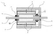
도 2는 본 발명 직류 전동기를 도시해 보인 단면도이고, 도 3는 본 발명 직류 전동기를 도시해 보인 평면도이며, 도 4는 본 발명 직류 전동기의 회전자를 도시해 보인 사시도이고, 도 5은 본 발명 직류 전동기의 회전자를 도시해 보인 정면도이며, 도 7은 본 발명 직류 전동기를 도시해 보인 일부 절개 사시도이다.3 is a plan view of a DC motor according to the present invention, FIG. 4 is a perspective view showing a rotor of the DC motor of the present invention, FIG. 5 is a cross- FIG. 7 is a partially cutaway perspective view showing a DC motor of the present invention. FIG. 7 is a front view showing a rotor of a DC motor.
본 발명 직류 전동기(1)는 회전자(4)의 내부와 외부에 외측 고정자(3)와 제 1 내측 고정자(2)가 배치된 상태에서 외측 고정자(3)와 제 1 내측 고정자(2)의 내측과 외측에 원통형의 자계를 형성하고 회전자(4)의 도체막대가 슬립링(10)과 브러쉬(11)를 통해서 일방향으로 전류가 흐르게 하여 회전한다.A
상기 외측 고정자(3)의 제 1 내측 고정자(2)의 내외측에 원통형상의 영구자석(6)이 자로가 형성되도록 계철(요크)를 구비하여 자계를 강하게 해준다.(Yoke) is provided on the inner and outer sides of the first
본 발명은 기본원리에 입각한 원통형상의 영구자석(6)이 외측 고정자(3)와 내측 고정자(2)에 위치하여 원통의 중심으로부터 방사되는 자계를 형성한다.A cylindrical permanent magnet (6) based on the basic principle is placed in the outer stator (3) and the inner stator (2) to form a magnetic field radiated from the center of the cylinder.
상기 외측 영구자석(6)과 내측 영구자석(6)사이에 회전자(4)의 도체막대(14)가 놓이게 되고 회전자(4)의 도체막대(14)에는 양측에 단락판(5)이 결합된다.A
상기 단락판(5)의 중앙에는 회전축(9)이 삽입되는 회전공이 형성되고, 상기 단락판(5)에 형성된 회전공의 둘레에는 슬립링(10)이 일체로 형성된다.A rotation hole into which the
상기 슬립링(10)에는 좌우 한 쌍으로 형성된 브러쉬(11)가 각각 부착된 상태에서 슬립링(10)과 제 1 내측 고정자(2)와 슬립링(10)과 외측 고정자(3)에 형성된 회전공으로 회전축(9)이 삽입된다.The
따라서 도 3의 도면에서 원통형의 자계속에 놓인 도체막대(14)는 지면에서 수직으로 전류가 나오는 방향으로 흐르며 플레밍의 왼손 법칙에 의해서 시계 방향으로 회전한다. 여기서 회전력은 수식 F=BIL 에 의해 회전하게 된다.Therefore, in the drawing of FIG. 3, the
상기 도체막대(14)는 회전자와 일체형이고 회전자(4)의 좌우 양측에는 단락판(5)이 구비되며, 양측의 단락판에는 2개의 슬립링(10)과 브러쉬(11)에 의해 전류는 일방향으로만 흐르게 설계하고, 원통형의 연속적인 자계속에 놓인 도체막대(14)는 일방향으로 흐르는 전류에 의해 회전력을 갖게 되어 회전하는 원리이다. 따라서 회전자(4)의 외측과 내측에 위치한 영구자석(6)은 계철(요크)에 의해 자로가 형성되게 함으로써 더욱더 강한 자계를 만들 수 있다. 상기 슬립링(10)은 회전자(4)와 일체형이므로 회전축(9)의 베어링(13)에 본 기능을 포함하도록 제작하여 회전 마찰력을 줄 일수도 있겠다.The
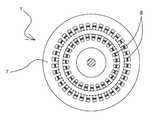
도 6는 본 발명 회전자(4)의 다른 실시 예로 냉각 홀이 형성된 것을 도시해 보인 사시도로서, 회전자(4)의 일측에는 + 전류의 회전 전극이 구비되고, 반대편에는 - 전류의 회전 전극이 구비되는 원통형의 판도체로 원통 표면에 전류의 흐름을 제어하고 냉각효과를 높이도록 냉각홀(15)이 형성된다.6 is a perspective view showing a cooling hole formed in another embodiment of the
도 8은 본 발명 직류 전동기의 권선 상태를 도시해 보인 평면도로써 고가의 희토류계 영구자석 대신 계자권선을 이용하여 자계를 형성하는 방식을 표현한 것으로 계자권선에 의해 N극과 S극을 형성하도록 결선하여 종래의 타여자 전동기, 분권 전동기, 복권 전동기, 직권 전동기, 가동복권 전동기, 차동복권 전동기형식으로 운용이 가능하다.8 is a plan view showing the winding state of the DC motor according to the present invention, which is a method of forming a magnetic field using a field winding instead of an expensive rare-earth permanent magnet, and is connected to form an N pole and an S pole by field windings It can be operated in the form of a conventional three-phase induction motor, a decentralized electric motor, a lottery electric motor, a direct electric motor, an active lottery electric motor, and a differential lottery electric motor.
도 9는 본 발명 직류 전동기의 다른 실시 예를 도시해 보인 단면도이고,9 is a cross-sectional view showing another embodiment of the DC motor of the present invention,
도 10은 도 9 직류 전동기를 도시해 보인 평면도이며, 도 11은 도 9 직류 전동기(1)의 권선상태를 도시해 보인 평면도이다.Fig. 10 is a plan view showing the DC motor of Fig. 9, and Fig. 11 is a plan view showing the state of the winding of the
본 발명 직류 전동기(1)는 일측 단부가 개방된 원통형상의 외측 고정자(3)와, 상기 외측 고정자(3)의 내부 중앙에는 동축선상으로 연결축(16)이 형성되고, 상기 연결축(16)의 일측 단부에는 원통형상으로 일측 단부가 개방된 제 1 내측 고정자(2)와, 상기 제 1 내측 고정자(2)의 내주면 중앙에는 동축선상으로 형성된 연결축(16)과, 상기 연결축(16)의 일축 단부에는 원통형상으로 일측 단부가 개방된 제 2 내측 고정자(2')와, 외측 고정자(3)와 제 1, 2 내측 고정자(2, 2')의 중앙에 형성된 회전공과, 상기 제 1, 2 내측 고정자(2, 2')의 외주면에 각각 위치하도록 결합된 회전자(4)와, 상기 외측 고정자(3)와 제 1, 2 내측 고정자(2, 2') 사이에 위치하는 영구자석(6)과, 상기 회전공으로 삽입 결합된 회전축(9)과, 상기 제 1, 2 내측 고정자(2, 2')를 연결하는 연결축(16)의 외주면에 위치하는 회전자(4)와 일체형인 슬립링(10)과, 상기 슬립링(10)에 각각 결합된 브러쉬(11)로 이루어진 상태에서 회전자(4)의 일측 단부에 위치하여 + 전류가 흐르는 브러쉬(11)와, 슬립링(10)을 통해서 회전자(4)의 타측 단부에 위치하여 - 전류가 흐르는 브러쉬(11)와 슬립링(10)으로 전류가 왕복 흐르게 형성하고, 회전이 원활하도록 원통형의 방사자계를 서로 반대방향으로 배열하여 자로를 형성하는 계철(요크)이 구비된다.A
또한, 영구자석(6)을 대신하여 계자권선(8)에 의해 계자(7)에 원형의 방사자계를 형성한다.In addition, a circular radiation magnetic field is formed in the
상기 직류 전동기(1)의 전류는 +쪽 슬립링(10)과 브러쉬(11)를 통해서 입력되면 - 쪽 슬립링(10)과 브러쉬(11)방향으로 나오게 된다.The current of the direct current
또한, 회전자(4)에 흐르는 전류의 흐름이 서로 반대방향이므로 이에 따른 원형의 방사자계 역시 반대방향으로 배치하여 회전력이 상쇄되지 않도록 한다.Since the flow of the current flowing through the
이 또한 계철(요크)에 의해 외측 영구자석(6)의 N극과 내측 영구자석(6)의 N극이 가운데 S극 계철(요크)로 자로가 형성되게 함으로써 자계의 세기를 강하게 할 수 있다.In addition, the N pole of the outer
도 12는 본 발명 직류 전동기의 다른 실시 예에 스위치가 연결된 상태를 도시해 보인 단면도로서, 본 발명 직류 전동기(1)는 일측 단부가 개방된 원통형상의 외측 고정자(3)와, 상기 외측 고정자(3)의 내부 중앙에는 동축선상으로 연결축(16)이 형성되고, 상기 연결축(16)의 일측 단부에는 원통형상으로 일측 단부가 개방된 제 1 내측 고정자(2)와, 상기 제 1 내측 고정자(2)의 내주면 중앙에는 동축선상으로 형성된 연결축(16)과, 상기 연결축(16)의 일축 단부에는 원통형상으로 일측 단부가 개방된 제 2 내측 고정자(2')와, 상기 제 2 내측 고정자(2')의 내주면 중앙에 형성된 연결축(16)과, 상기 연결축(16)의 일측 단부에는 제 3 내측 고정자(2")가 위치하여 일체로 형성된 상태에서 외측 고정자(3)와, 제 1, 2, 3 내측 고정자(2, 2', 2")의 중앙에 형성된 회전공과, 상기 제 1, 2, 3 내측 고정자(2, 2', 2")의 외주면에 각각 위치하도록 결합된 회전자(4)와, 상기 외측 고정자(3)와 제 1, 2, 3 내측 고정자(2, 2', 2") 사이에 위치하는 영구자석(6)과, 상기 회전공으로 삽입 결합된 회전축(9)과, 상기 제 1, 2, 3 내측 고정자(2, 2',2")를 연결하는 연결축(16)의 외주면에 위치하는 회전자(4)의 슬립링(10)과, 상기 슬립링(10)에 각각 결합된 브러쉬(11)로 이루어진 상태에서 회전자(4)의 일측 단부에 위치하여 + 전류가 흐르는 브러쉬(11)와, 슬립링(10)을 통해서 회전자(4)의 타측 단부에 위치하여 - 전류가 흐르는 브러쉬(11) 슬립링(10)으로 전류가 흐르게 형성하고, 회전이 원활하도록 원형의 방사자계를 서로 같은 방향으로 배열하여 자로를 형성하는 계철(요크)이 구비된다.FIG. 12 is a cross-sectional view showing a state where a switch is connected to another embodiment of the DC motor of the present invention. The
제 1, 2, 3 내측 고정자(2, 2', 2")의 일측 단부에는 동축선상으로 영구자석(6)이 위치한다. 상기 제 1, 2, 3 내측 고정자를 연결하는 연결축(16)에 위치하는 회전자(4)의 슬립링(10)에 결합된 브러쉬(11)에 각각 스위치가 연결되고, 상기 각각의 스위치를 통해 회전자(4)의 도체막대에 전류를 선택 공급함으로써 회전 토크와 속도를 조절할 수 있다. 이는 회전자(4)의 크기를 서로 다르게 하여 다단 배치하고 스위치(12)에 의해 전류의 공급을 선택 공급할 수 있게 함으로써 회전 토크를 조절할 수 있는 구조이다.The
일반적으로 직류 전동기(1)는 시동전류가 정격전류의 6배에 달하게 된다. 따라서 직류 전동기(1) 운전시 정지와 출발을 연속적으로 할 경우 효율이 매우 떨어지게 되는데, 본 발명에 의해 출발시에는 회전반경이 큰 쪽의 회전자(4)에 전류를 공급하고 고속회전일 경우 회전반경이 작은 회전자에 전류를 선택 공급함으로써 효율을 높이고자 함이다. 이는 직류 전동기(1)를 이용한 전동차에 매우 유용할 것으로 판단된다.Generally, the starting current of the
또한, 본 발명 직류 전동기(1)는 내측 고정자 및 회전자를 3단까지 표현하였으나 3단 이상의 다 단으로 구현할 수도 있다.Further, although the internal stator and the rotor are represented by three stages in the
도 13은 본 발명 직류 전동기의 제어흐름 상태를 도시해 보인 블록도이다. 본 발명은 직류 전동기(1)를 구동할 수 있는 제어회로로써 직류 전동기(1)의 저항값과 인덕턴스값이 0에 가깝기 때문에 전용의 구동회로를 필요로 하며 PWM(Pulse Width Modulation)방식과 인덕터(18)를 직렬로 구성하여 전류를 제한함으로써 효율을 높일 수 있다.13 is a block diagram showing the control flow state of the DC motor of the present invention. The present invention is a control circuit capable of driving a DC motor (1). Since the resistance value and inductance value of the DC motor (1) are close to zero, a dedicated driving circuit is required and a PWM (Pulse Width Modulation) 18) are connected in series to limit the current, thereby increasing the efficiency.
본 발명의 제어블록도는 일 실시 예로써 직류 전동기(1) 속도를 입력받아 현재 직류 전동기(1)의 속도와 비교한후 PI(비례,적분제어)제어가 이루어 지고 전류를 피드백 받아 비교된후 다시 PI(비례,적분제어)제어가 이루어 진다. 직류 전원은 PWM(Pulse Width Modulation) 발생회로에 펄스전류로 변환되며 인덕터(18)와 콘덴서(19)를 통해 전류제한 및 직류전류로 변환되어 직류 전동기(1)에 인가된다.The control block diagram of the present invention is a control block diagram in which the speed of the
일반적으로 인덕터(18)의 유도성 리액턴스는
상기 발명의 고효율 직류 전동기(1)는 저항과 인덕턴스값이 매우 작기 때문에 PWM과 인덕터(18)에 의한 전류제한회로가 반드시 필요하며 인덕터(18)는 에너지를 소비하는 소자가 아니므로 전체적으로 직류 전동기(1)의 효율은 높아지게 된다. PWM회로는 종래의 IC방식을 활용할 수 있으며 드라이브 소자에는 TR, FET, IGBT등을 활용할 수 있겠다.Since the high
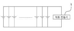
도 14는 본 발명 직류 전동기의 축전지 병렬 연결상태를 도시해 보인 예시도 이다. 본 발명 직류 전동기(1)는 저항값과 인덕턴스값이 0에 가까우므로 저전압 구동이 용이한 장점을 가지고 있다. 특히 축전지에 의한 운전의 경우 종래의 직렬연결시 방식에서 탈피하여 병렬연결식 축전지를 활용할 수 있게 됨으로써 축전지의 수명증가와 급속충전에 유리하다. 직렬연결식 축전지의 경우 축전지의 모든 셀을 한번에 충방전 함으로써 셀 하나가 과충전되어 파손될 수도 있는데 셀 하나가 파손되면 축전지 전체를 못 쓰게 되나, 이에 반해 병렬 연결식 축전지에서는 셀 하나씩 충방전을 제어함으로써 과충전되는 것을 방지하고 만일 셀 하나가 파손되었다 하더라도 축전지 전체를 못 쓰게 되지는 않는 장점이 있다. 이는 결과적으로 축전지의 수명을 연장하고, 급속충전을 할 수 있는 장점이 있다.
FIG. 14 is an exemplary view showing the parallel connection of a DC motor according to the present invention. FIG. INDUSTRIAL APPLICABILITY The DC motor (1) of the present invention is advantageous in that it can be easily driven at a low voltage since the resistance value and the inductance value are close to zero. Particularly, in the case of operation by a battery, it is possible to utilize a parallel-connected battery by breaking away from a conventional method of series connection, which is advantageous for an increase in the life of the battery and rapid charging. In the case of a series-connected battery, one cell can be overcharged and destroyed by charging / discharging all the cells of the battery at once. If one cell is broken, the entire battery can not be used. On the other hand, in a parallel-connected battery, And it is advantageous that even if one cell is broken, the whole battery can not be damaged. As a result, the life of the battery can be prolonged and rapid charging can be performed.
1: 직류 전동기 2, 2', 2": 제 1, 2, 3 내측 고정자
3: 외측 고정자 4: 회전자
5: 단락판 6: 영구자석
7: 계자 8: 계자권선
9: 회전축 10: 슬립링
11: 브러쉬 12: 스위치
13: 베어링 14: 도체막대
15: 냉각홀 16: 연결축
17: 도체판 18: 인덕터
19: 콘덴서1:
3: outer stator 4: rotor
5: Parallel plate 6: Permanent magnet
7: Field winding 8: Field winding
9: rotation shaft 10: slip ring
11: Brush 12: Switch
13: bearing 14: conductor rod
15: cooling hole 16: connection axis
17: conductor plate 18: inductor
19: Condenser
Claims (8)
Translated fromKorean상기 회전자(4)의 내부와 외부에는 외측 고정자(3)와 제 1 내측 고정자(2)가 배치된 상태에서, 상기 외측 고정자(3)와 제 1 내측 고정자(2)의 내측과 외측에는 영구자석(6)으로 원통형의 방사자계를 형성하고 회전자(4)의 도체막대(14)가 슬립링(10)과 브러쉬(11)를 통해서 일방향으로 전류가 흐르게 하여 회전하는 것을 특징으로 하는 고효율 직류 전동기.
In a DC motor in which a rotor rotating by a rotating shaft is positioned inside a stator to generate an electric rotating force,
The inner and outer sides of the outer stator 3 and the first inner stator 2 are permanently fixed to the inner and outer sides of the rotor 4 in a state in which the outer stator 3 and the first inner stator 2 are disposed. Characterized in that a cylindrical radial magnetic field is formed by the magnet (6) and the conductor rod (14) of the rotor (4) rotates with current flowing in one direction through the slip ring (10) and the brush (11) Electric motor.
2. A permanent magnet according to claim 1, characterized in that a magnetic field is strengthened by providing a yoke (yoke) such that a cylindrical permanent magnet (6) is formed on the inner and outer sides of the outer stator (3) and the first inner stator DC motor.
The motor according to claim 1, wherein the DC motor (1) comprises a cylindrical outer stator (3) having an open end and a connecting shaft (16) formed coaxially with the inner center of the outer stator (3) A connecting shaft 16 formed coaxially at the center of the inner circumferential surface of the first inner stator 2 and a connecting shaft 16 formed at one end of the connecting shaft 16 in a cylindrical shape, The outer stator 3 and the first and second inner stator 2 and 2 'are integrally formed at the one axial end of the connecting shaft 16 in a state where the second inner stator 2' A rotor 4 coupled to be positioned on the outer circumferential surfaces of the first and second inner stator 2 and 2 'and a rotor 4 coupled to the outer stator 3 and the first and second inner stator 2 , A permanent magnet (6) located between the first and second inner stator (2, 2 '), 2', a rotary shaft (9) A slip ring 10 positioned at an outer surface of a connecting shaft 16 connecting the slip ring 10 and a brush 11 coupled to the slip ring 10, A current flowing through the brush 11 and the slip ring 10 is formed at the other end of the rotor so that the current flows in the brush 11 and the slip ring 10 through which current flows, And a column for forming a magnetic path by disposing a cylindrical radiation magnetic field in directions opposite to each other.
The internal combustion engine according to claim 1, wherein the direct current electric motor (1) comprises a cylindrical outer stator (3) having one open end and a first internal stator (2), a first internal stator 2 and 3 inner stator 2 'with the second inner stator 2' inside and the third inner stator 2 'inside the second inner stator 2' The permanent magnets 6 are disposed between the outer stator 3 and the first, second and third inner stator 2, 2 ', 2 " And a rotary shaft (9) is coupled to the center of the outer stator (3), the first, second and third inner stator (2, 2 ', 2 ") and the rotor.
The brushless motor according to claim 4, characterized in that a brush (11) coupled to a slip ring (10) located on a connecting shaft (16) connecting the first, second and third inner stator (2, 2 ' 12. A high efficiency direct current electric motor as claimed in claim 1, wherein a current is selectively supplied to the conductor rod (14) of the rotor (4) through the switch (12).
The high-efficiency direct-current motor according to any one of claims 1 to 4, wherein a cylindrical radial magnetic field can be formed by a field coil and a field coil instead of the permanent magnet (6).
5. A rotor according to any one of claims 1 to 4, wherein a rotor electrode of + current is provided on one side of the rotor (4) and a rotating electrode of current is provided on the opposite side, And a cooling hole (15) is formed to control the flow of current on the surface and to enhance the cooling effect.
Priority Applications (1)
| Application Number | Priority Date | Filing Date | Title |
|---|---|---|---|
| KR1020150120135AKR20170024744A (en) | 2015-08-26 | 2015-08-26 | The high efficiency direct current motor and thereof control method |
Applications Claiming Priority (1)
| Application Number | Priority Date | Filing Date | Title |
|---|---|---|---|
| KR1020150120135AKR20170024744A (en) | 2015-08-26 | 2015-08-26 | The high efficiency direct current motor and thereof control method |
Publications (1)
| Publication Number | Publication Date |
|---|---|
| KR20170024744Atrue KR20170024744A (en) | 2017-03-08 |
Family
ID=58404160
Family Applications (1)
| Application Number | Title | Priority Date | Filing Date |
|---|---|---|---|
| KR1020150120135ACeasedKR20170024744A (en) | 2015-08-26 | 2015-08-26 | The high efficiency direct current motor and thereof control method |
Country Status (1)
| Country | Link |
|---|---|
| KR (1) | KR20170024744A (en) |
Cited By (5)
| Publication number | Priority date | Publication date | Assignee | Title |
|---|---|---|---|---|
| CN109639102A (en)* | 2018-12-25 | 2019-04-16 | 李建文 | Electromagnetic actuator device and electric car |
| KR20220121686A (en)* | 2021-02-25 | 2022-09-01 | 권오찬 | smart generator |
| CN115102351A (en)* | 2021-02-25 | 2022-09-23 | 权五赞 | Smart generator |
| KR20230039303A (en)* | 2021-09-14 | 2023-03-21 | 주식회사 페리만앤티젠 | Permanent Magnet Generator System |
| WO2025106749A1 (en)* | 2023-11-14 | 2025-05-22 | Iacovelli Benedetto | Improved intrinsically adapting variable generators and motors |
Citations (1)
| Publication number | Priority date | Publication date | Assignee | Title |
|---|---|---|---|---|
| KR20050013379A (en) | 2003-07-28 | 2005-02-04 | (주)바른기술 | Examination method for of semiconductor chip and method for measuring the total height and stand-off of semiconductor chip |
- 2015
- 2015-08-26KRKR1020150120135Apatent/KR20170024744A/ennot_activeCeased
Patent Citations (1)
| Publication number | Priority date | Publication date | Assignee | Title |
|---|---|---|---|---|
| KR20050013379A (en) | 2003-07-28 | 2005-02-04 | (주)바른기술 | Examination method for of semiconductor chip and method for measuring the total height and stand-off of semiconductor chip |
Cited By (5)
| Publication number | Priority date | Publication date | Assignee | Title |
|---|---|---|---|---|
| CN109639102A (en)* | 2018-12-25 | 2019-04-16 | 李建文 | Electromagnetic actuator device and electric car |
| KR20220121686A (en)* | 2021-02-25 | 2022-09-01 | 권오찬 | smart generator |
| CN115102351A (en)* | 2021-02-25 | 2022-09-23 | 权五赞 | Smart generator |
| KR20230039303A (en)* | 2021-09-14 | 2023-03-21 | 주식회사 페리만앤티젠 | Permanent Magnet Generator System |
| WO2025106749A1 (en)* | 2023-11-14 | 2025-05-22 | Iacovelli Benedetto | Improved intrinsically adapting variable generators and motors |
Similar Documents
| Publication | Publication Date | Title |
|---|---|---|
| CN101772876B (en) | Motors with hybrid field rotors | |
| JP5922023B2 (en) | Electric motor and / or generator with a mechanically variable permanent magnetic field | |
| US20120169161A1 (en) | Disk motor using a permanent magnet and bypassing the magnetic force of the magnet | |
| EP3062426A1 (en) | Single-phase brushless motor | |
| US7884580B2 (en) | Constant-power brushless DC motor and the generator thereby | |
| US8710779B2 (en) | Brushless electric motor or generator in shell construction | |
| US8575871B1 (en) | Modular component electric machine | |
| KR20170024744A (en) | The high efficiency direct current motor and thereof control method | |
| US11949289B2 (en) | Electric motors | |
| CN101438485A (en) | Electric power generator, method for generating electric power, and motor | |
| KR20170007273A (en) | Wound field synchronous machine with resonant field exciter | |
| US20150091403A1 (en) | Transverse flux machine and vehicle | |
| WO2007048211A2 (en) | Permanent magnet rotor | |
| GB2468695A (en) | A stator assembly incorporating permanent magnets and wound field poles for an inductor machine. | |
| US8373328B2 (en) | Pulsed multi-rotor constant air gap switched reluctance motor | |
| CN112910130A (en) | Rotor magnetic pole modulation type variable magnetic flux memory motor | |
| JPH03103091A (en) | Three-phase reluctance motor | |
| AU2018309956B2 (en) | Rotary Electric Machine | |
| US11722043B2 (en) | Synchronous machine having hybrid rotor excitation | |
| US9099912B2 (en) | Electromagnetic coupling | |
| JP5460807B1 (en) | Synchronous motor | |
| KR102571343B1 (en) | Commutation-less DC motor using symmetrically structured the same directional rotation-wise magnetic fields and axis-wise magnetic fields generated around air-gap between rotor and stator | |
| US20240413686A1 (en) | Brushless Electric Machine and Method of Manufacturing the Brushless Electric Machine | |
| WO2019155961A1 (en) | Reluctance motor and motor system comprising said reluctance motor | |
| US20240413684A1 (en) | Brushless Electric Machine and Method of Manufacturing a Brushless Electric Machine |
Legal Events
| Date | Code | Title | Description |
|---|---|---|---|
| A201 | Request for examination | ||
| PA0109 | Patent application | Patent event code:PA01091R01D Comment text:Patent Application Patent event date:20150826 | |
| PA0201 | Request for examination | ||
| E902 | Notification of reason for refusal | ||
| PE0902 | Notice of grounds for rejection | Comment text:Notification of reason for refusal Patent event date:20160729 Patent event code:PE09021S01D | |
| PG1501 | Laying open of application | ||
| E601 | Decision to refuse application | ||
| PE0601 | Decision on rejection of patent | Patent event date:20170322 Comment text:Decision to Refuse Application Patent event code:PE06012S01D Patent event date:20160729 Comment text:Notification of reason for refusal Patent event code:PE06011S01I |