KR20170024279A - Apparatus for removing noxious gas and offensive odor - Google Patents
Apparatus for removing noxious gas and offensive odorDownload PDFInfo
- Publication number
- KR20170024279A KR20170024279AKR1020150119329AKR20150119329AKR20170024279AKR 20170024279 AKR20170024279 AKR 20170024279AKR 1020150119329 AKR1020150119329 AKR 1020150119329AKR 20150119329 AKR20150119329 AKR 20150119329AKR 20170024279 AKR20170024279 AKR 20170024279A
- Authority
- KR
- South Korea
- Prior art keywords
- air
- adsorption filter
- inner space
- housing
- harmful gas
- Prior art date
- Legal status (The legal status is an assumption and is not a legal conclusion. Google has not performed a legal analysis and makes no representation as to the accuracy of the status listed.)
- Ceased
Links
- 239000002341toxic gasSubstances0.000titledescription9
- 150000002500ionsChemical class0.000claimsabstractdescription54
- 238000001179sorption measurementMethods0.000claimsabstractdescription52
- 239000000356contaminantSubstances0.000claimsabstractdescription36
- 238000007664blowingMethods0.000claimsabstractdescription24
- 238000001914filtrationMethods0.000claimsabstractdescription17
- 239000010457zeoliteSubstances0.000claimsdescription34
- 229910021536ZeoliteInorganic materials0.000claimsdescription33
- HNPSIPDUKPIQMN-UHFFFAOYSA-Ndioxosilane;oxo(oxoalumanyloxy)alumaneChemical compoundO=[Si]=O.O=[Al]O[Al]=OHNPSIPDUKPIQMN-UHFFFAOYSA-N0.000claimsdescription32
- BPQQTUXANYXVAA-UHFFFAOYSA-NOrthosilicateChemical compound[O-][Si]([O-])([O-])[O-]BPQQTUXANYXVAA-UHFFFAOYSA-N0.000claimsdescription28
- UNYSKUBLZGJSLV-UHFFFAOYSA-Lcalcium;1,3,5,2,4,6$l^{2}-trioxadisilaluminane 2,4-dioxide;dihydroxide;hexahydrateChemical compoundO.O.O.O.O.O.[OH-].[OH-].[Ca+2].O=[Si]1O[Al]O[Si](=O)O1.O=[Si]1O[Al]O[Si](=O)O1UNYSKUBLZGJSLV-UHFFFAOYSA-L0.000claimsdescription10
- 229910052676chabaziteInorganic materials0.000claimsdescription9
- 229910001657ferrierite groupInorganic materials0.000claimsdescription9
- 239000012013faujasiteSubstances0.000claimsdescription8
- 239000000463materialSubstances0.000claimsdescription8
- 238000000034methodMethods0.000claimsdescription7
- BASFCYQUMIYNBI-UHFFFAOYSA-NplatinumChemical compound[Pt]BASFCYQUMIYNBI-UHFFFAOYSA-N0.000claimsdescription6
- 238000007599dischargingMethods0.000claimsdescription5
- 229910052697platinumInorganic materials0.000claimsdescription3
- 229910018072Al 2 O 3Inorganic materials0.000claimsdescription2
- 239000004696Poly ether ether ketoneSubstances0.000claimsdescription2
- 229910004298SiO 2Inorganic materials0.000claimsdescription2
- BQCADISMDOOEFD-UHFFFAOYSA-NSilverChemical compound[Ag]BQCADISMDOOEFD-UHFFFAOYSA-N0.000claimsdescription2
- 239000004809TeflonSubstances0.000claimsdescription2
- 229920006362Teflon®Polymers0.000claimsdescription2
- 229910010413TiO 2Inorganic materials0.000claimsdescription2
- 229920000122acrylonitrile butadiene styrenePolymers0.000claimsdescription2
- 239000004676acrylonitrile butadiene styreneSubstances0.000claimsdescription2
- JUPQTSLXMOCDHR-UHFFFAOYSA-Nbenzene-1,4-diol;bis(4-fluorophenyl)methanoneChemical compoundOC1=CC=C(O)C=C1.C1=CC(F)=CC=C1C(=O)C1=CC=C(F)C=C1JUPQTSLXMOCDHR-UHFFFAOYSA-N0.000claimsdescription2
- CPLXHLVBOLITMK-UHFFFAOYSA-Nmagnesium oxideInorganic materials[Mg]=OCPLXHLVBOLITMK-UHFFFAOYSA-N0.000claimsdescription2
- 229910052751metalInorganic materials0.000claimsdescription2
- 239000002184metalSubstances0.000claimsdescription2
- 239000012994photoredox catalystSubstances0.000claimsdescription2
- 239000004417polycarbonateSubstances0.000claimsdescription2
- 229920002530polyetherether ketonePolymers0.000claimsdescription2
- 229920001343polytetrafluoroethylenePolymers0.000claimsdescription2
- 239000004810polytetrafluoroethyleneSubstances0.000claimsdescription2
- 229910052709silverInorganic materials0.000claimsdescription2
- 239000004332silverSubstances0.000claimsdescription2
- WFKWXMTUELFFGS-UHFFFAOYSA-NtungstenChemical compound[W]WFKWXMTUELFFGS-UHFFFAOYSA-N0.000claimsdescription2
- 229910052721tungstenInorganic materials0.000claimsdescription2
- 239000010937tungstenSubstances0.000claimsdescription2
- 229910052726zirconiumInorganic materials0.000claimsdescription2
- 239000003344environmental pollutantSubstances0.000abstractdescription20
- 231100000719pollutantToxicity0.000abstractdescription20
- 230000000694effectsEffects0.000abstractdescription10
- CBENFWSGALASAD-UHFFFAOYSA-NOzoneChemical compound[O-][O+]=OCBENFWSGALASAD-UHFFFAOYSA-N0.000abstractdescription6
- 239000000126substanceSubstances0.000abstractdescription6
- 230000001939inductive effectEffects0.000abstractdescription3
- 239000007789gasSubstances0.000description27
- 235000019645odorNutrition0.000description19
- 239000002245particleSubstances0.000description13
- 239000003153chemical reaction reagentSubstances0.000description12
- 239000011148porous materialSubstances0.000description11
- -1molecular oxygen ionsChemical class0.000description10
- 239000001301oxygenSubstances0.000description8
- 229910052760oxygenInorganic materials0.000description8
- 125000002887hydroxy groupChemical group[H]O*0.000description7
- UHOVQNZJYSORNB-UHFFFAOYSA-NBenzeneChemical compoundC1=CC=CC=C1UHOVQNZJYSORNB-UHFFFAOYSA-N0.000description6
- 241000233866FungiSpecies0.000description6
- 230000005684electric fieldEffects0.000description6
- 241000894006BacteriaSpecies0.000description5
- 239000003814drugSubstances0.000description4
- 229940079593drugDrugs0.000description4
- 239000000428dustSubstances0.000description4
- YXFVVABEGXRONW-UHFFFAOYSA-NTolueneChemical compoundCC1=CC=CC=C1YXFVVABEGXRONW-UHFFFAOYSA-N0.000description3
- 150000001450anionsChemical class0.000description3
- 238000006243chemical reactionMethods0.000description3
- 239000003989dielectric materialSubstances0.000description3
- 238000002474experimental methodMethods0.000description3
- 238000007639printingMethods0.000description3
- QGZKDVFQNNGYKY-UHFFFAOYSA-NAmmoniaChemical compoundNQGZKDVFQNNGYKY-UHFFFAOYSA-N0.000description2
- RWSOTUBLDIXVET-UHFFFAOYSA-NDihydrogen sulfideChemical compoundSRWSOTUBLDIXVET-UHFFFAOYSA-N0.000description2
- QVGXLLKOCUKJST-UHFFFAOYSA-Natomic oxygenChemical compound[O]QVGXLLKOCUKJST-UHFFFAOYSA-N0.000description2
- 244000052616bacterial pathogenSpecies0.000description2
- 239000006227byproductSubstances0.000description2
- 210000004027cellAnatomy0.000description2
- 125000000524functional groupChemical group0.000description2
- 238000005259measurementMethods0.000description2
- VNWKTOKETHGBQD-UHFFFAOYSA-NmethaneChemical compoundCVNWKTOKETHGBQD-UHFFFAOYSA-N0.000description2
- 230000003472neutralizing effectEffects0.000description2
- 239000004745nonwoven fabricSubstances0.000description2
- 230000001473noxious effectEffects0.000description2
- 150000002978peroxidesChemical class0.000description2
- 230000001954sterilising effectEffects0.000description2
- 239000012855volatile organic compoundSubstances0.000description2
- XLYOFNOQVPJJNP-UHFFFAOYSA-NwaterChemical compoundOXLYOFNOQVPJJNP-UHFFFAOYSA-N0.000description2
- UFHFLCQGNIYNRP-UHFFFAOYSA-NHydrogenChemical compound[H][H]UFHFLCQGNIYNRP-UHFFFAOYSA-N0.000description1
- 241000700605VirusesSpecies0.000description1
- IKHGUXGNUITLKF-XPULMUKRSA-NacetaldehydeChemical compound[14CH]([14CH3])=OIKHGUXGNUITLKF-XPULMUKRSA-N0.000description1
- 150000001412aminesChemical class0.000description1
- 229910021529ammoniaInorganic materials0.000description1
- 238000010420art techniqueMethods0.000description1
- 150000001768cationsChemical class0.000description1
- 210000000170cell membraneAnatomy0.000description1
- 238000004140cleaningMethods0.000description1
- 238000004891communicationMethods0.000description1
- 238000000748compression mouldingMethods0.000description1
- 239000004020conductorSubstances0.000description1
- 229910052802copperInorganic materials0.000description1
- 238000000354decomposition reactionMethods0.000description1
- 238000010586diagramMethods0.000description1
- 229910001882dioxygenInorganic materials0.000description1
- 229920006351engineering plasticPolymers0.000description1
- 238000005516engineering processMethods0.000description1
- 239000004744fabricSubstances0.000description1
- 239000010419fine particleSubstances0.000description1
- 239000011521glassSubstances0.000description1
- 239000001257hydrogenSubstances0.000description1
- 229910052739hydrogenInorganic materials0.000description1
- 229910000037hydrogen sulfideInorganic materials0.000description1
- 229910052742ironInorganic materials0.000description1
- WSFSSNUMVMOOMR-NJFSPNSNSA-NmethanoneChemical compoundO=[14CH2]WSFSSNUMVMOOMR-NJFSPNSNSA-N0.000description1
- 238000000465mouldingMethods0.000description1
- 229910052759nickelInorganic materials0.000description1
- 239000012811non-conductive materialSubstances0.000description1
- 150000002894organic compoundsChemical class0.000description1
- 125000002081peroxide groupChemical group0.000description1
- 230000010287polarizationEffects0.000description1
- 239000010453quartzSubstances0.000description1
- 238000012827research and developmentMethods0.000description1
- VYPSYNLAJGMNEJ-UHFFFAOYSA-Nsilicon dioxideInorganic materialsO=[Si]=OVYPSYNLAJGMNEJ-UHFFFAOYSA-N0.000description1
- 238000004659sterilization and disinfectionMethods0.000description1
- 239000000021stimulantSubstances0.000description1
- 238000012546transferMethods0.000description1
- 229910052725zincInorganic materials0.000description1
Images


Classifications
- B—PERFORMING OPERATIONS; TRANSPORTING
- B01—PHYSICAL OR CHEMICAL PROCESSES OR APPARATUS IN GENERAL
- B01D—SEPARATION
- B01D46/00—Filters or filtering processes specially modified for separating dispersed particles from gases or vapours
- B01D46/0027—Filters or filtering processes specially modified for separating dispersed particles from gases or vapours with additional separating or treating functions
- A—HUMAN NECESSITIES
- A61—MEDICAL OR VETERINARY SCIENCE; HYGIENE
- A61L—METHODS OR APPARATUS FOR STERILISING MATERIALS OR OBJECTS IN GENERAL; DISINFECTION, STERILISATION OR DEODORISATION OF AIR; CHEMICAL ASPECTS OF BANDAGES, DRESSINGS, ABSORBENT PADS OR SURGICAL ARTICLES; MATERIALS FOR BANDAGES, DRESSINGS, ABSORBENT PADS OR SURGICAL ARTICLES
- A61L9/00—Disinfection, sterilisation or deodorisation of air
- A61L9/16—Disinfection, sterilisation or deodorisation of air using physical phenomena
- A61L9/22—Ionisation
- B—PERFORMING OPERATIONS; TRANSPORTING
- B01—PHYSICAL OR CHEMICAL PROCESSES OR APPARATUS IN GENERAL
- B01D—SEPARATION
- B01D46/00—Filters or filtering processes specially modified for separating dispersed particles from gases or vapours
- B01D46/10—Particle separators, e.g. dust precipitators, using filter plates, sheets or pads having plane surfaces
- B01D46/12—Particle separators, e.g. dust precipitators, using filter plates, sheets or pads having plane surfaces in multiple arrangements
- B—PERFORMING OPERATIONS; TRANSPORTING
- B03—SEPARATION OF SOLID MATERIALS USING LIQUIDS OR USING PNEUMATIC TABLES OR JIGS; MAGNETIC OR ELECTROSTATIC SEPARATION OF SOLID MATERIALS FROM SOLID MATERIALS OR FLUIDS; SEPARATION BY HIGH-VOLTAGE ELECTRIC FIELDS
- B03C—MAGNETIC OR ELECTROSTATIC SEPARATION OF SOLID MATERIALS FROM SOLID MATERIALS OR FLUIDS; SEPARATION BY HIGH-VOLTAGE ELECTRIC FIELDS
- B03C3/00—Separating dispersed particles from gases or vapour, e.g. air, by electrostatic effect
- B03C3/34—Constructional details or accessories or operation thereof
- B03C3/38—Particle charging or ionising stations, e.g. using electric discharge, radioactive radiation or flames
- F—MECHANICAL ENGINEERING; LIGHTING; HEATING; WEAPONS; BLASTING
- F24—HEATING; RANGES; VENTILATING
- F24F—AIR-CONDITIONING; AIR-HUMIDIFICATION; VENTILATION; USE OF AIR CURRENTS FOR SCREENING
- F24F3/00—Air-conditioning systems in which conditioned primary air is supplied from one or more central stations to distributing units in the rooms or spaces where it may receive secondary treatment; Apparatus specially designed for such systems
- F24F3/12—Air-conditioning systems in which conditioned primary air is supplied from one or more central stations to distributing units in the rooms or spaces where it may receive secondary treatment; Apparatus specially designed for such systems characterised by the treatment of the air otherwise than by heating and cooling
- F24F3/16—Air-conditioning systems in which conditioned primary air is supplied from one or more central stations to distributing units in the rooms or spaces where it may receive secondary treatment; Apparatus specially designed for such systems characterised by the treatment of the air otherwise than by heating and cooling by purification, e.g. by filtering; by sterilisation; by ozonisation
- F—MECHANICAL ENGINEERING; LIGHTING; HEATING; WEAPONS; BLASTING
- F24—HEATING; RANGES; VENTILATING
- F24F—AIR-CONDITIONING; AIR-HUMIDIFICATION; VENTILATION; USE OF AIR CURRENTS FOR SCREENING
- F24F7/00—Ventilation
- F24F7/04—Ventilation with ducting systems, e.g. by double walls; with natural circulation
- F24F7/06—Ventilation with ducting systems, e.g. by double walls; with natural circulation with forced air circulation, e.g. by fan positioning of a ventilator in or against a conduit
Landscapes
- Engineering & Computer Science (AREA)
- Chemical & Material Sciences (AREA)
- Chemical Kinetics & Catalysis (AREA)
- Health & Medical Sciences (AREA)
- General Engineering & Computer Science (AREA)
- Mechanical Engineering (AREA)
- Combustion & Propulsion (AREA)
- Epidemiology (AREA)
- Veterinary Medicine (AREA)
- Public Health (AREA)
- General Health & Medical Sciences (AREA)
- Animal Behavior & Ethology (AREA)
- Life Sciences & Earth Sciences (AREA)
- Disinfection, Sterilisation Or Deodorisation Of Air (AREA)
Abstract
Translated fromKoreanDescription
Translated fromKorean본 발명은 공기 중에 포함된 유해가스 또는 악취를 유발물질 등과 같은 오염물질을 제거하여 깨끗한 공기로 정화하는 유해가스 및 악취 제거장치에 관한 것으로서, 보다 상세하면 송풍부재, 이온클러스터 생성모듈 및 필터링모듈이 구비된 함체의 내부공간으로 송풍부재를 이용하여 오염된 공기를 유입시키고, 함체의 내부로 유입된 오염된 공기에 포함된 오염물질을 이온클러스터 생성모듈에서 생성된 이온을 이용하여 1차적으로 제거한 후, 미제거된 오염물질을 포함할 수 있는 공기를 필터링모듈에 통과시켜 공기 중에 포함된 오염물질을 제거가능한 유해가스 및 악취 제거장치에 관한 분야이다.
The present invention relates to a harmful gas and a malodor removing apparatus for removing harmful gas or odor contained in air by removing pollutants such as inducing substances and purifying them with clean air, Contaminated air is introduced into the internal space of the enclosure using an air blowing member and the contaminants contained in the contaminated air flowing into the inside of the enclosure are primarily removed by using ions generated in the ion cluster generating module , And a device for removing harmful gases and odors which can remove contaminants contained in air by passing air that may contain contaminants that have not been removed to the filtering module.
일반적으로 실내공기, 산업 배기가스, 자동차 배기가스 또는 시약장 내부공기는 유해가스 또는 악취를 포함하고, 상기와 같은 오염물질이 포함된 공기를 사람이 그대로 흡입할 시에는 인체에 해롭게 된다.In general, indoor air, industrial exhaust gas, automobile exhaust gas, or air inside a reagent contain harmful gas or odor, and the human body suffers harm to the human body when the air containing the pollutant is inhaled.
일예로 실험실 또는 연구실은 여러 종류의 약품을 혼합하여 다양한 실험을 하게 되고, 또 실험에서 얻어진 시료를 분석 또는 배양 등의 연구작업을 수행하게 된다.For example, in a laboratory or a laboratory, various kinds of drugs are mixed to perform various experiments, and a sample obtained from the experiment is analyzed or cultured.
따라서 시약이나 배양물 등은 별도의 시약장에 보관하여 적정한 온/습도를 유지토록 하고 있다. 그러나 상기 실험 과정 또는 배양 과정에서 발생될 수 있는 유해가스, 미세먼지 또는 기타 바이러스 등이 실내 공기에 포함될 수 있고, 이로 인해 거주자의 건강을 위협할 우려가 있다.Therefore, reagents and cultures are stored in separate reagents to maintain proper temperature and humidity. However, noxious gases, fine dusts, or other viruses that may be generated during the above-described experiment or culture may be contained in the indoor air, which may cause a risk to the health of residents.
따라서 이러한 위험성을 방지하기 위해 실험실, 연구실 또는 기타 다중 이용시설의 실내에 공기를 정화시키기 위한 유해가스 제거장치가 필수적으로 설치된다.
Therefore, in order to prevent such a danger, a harmful gas removing device for purifying the air in a room of a laboratory, a laboratory or other multi-use facility is essentially installed.
다음은 유해가스 및 악취 제거장치에 관한 대표적인 종래기술이다.The following are representative prior art techniques for removing harmful gases and odors.
국내등록특허 제10-0959634호는 본 출원인이 선출원한 유해가스 중화 및 제거장치에 관한 것으로서, 상부에 흡입구가 형성되고 하부에 배출구가 형성되며, 내부에 수용공간이 형성된 함체; 상기 함체 내에 설치되며 흡입구를 통해 흡입력이 발휘되도록 하는 터보팬; 상기 함체 내에 설치되어 공기 중의 세균 및 유해가스를 살균 제거하는 이온 클러스터 발생기를 포함하고, 상기 함체의 내측에 설치되어 흡입된 공기를 살균하는 음이온 발생기가 더 포함되며, 상기 음이온 발생기는 함체 내에 다단으로 형성된 결합부재에 결합되어 위치 조절 및 착탈이 가능하도록한 것이며, 상기 결합부재는 일정 길이를 갖는 레일이고, 상기 음이온 발생기의 측면에는 상기 레일 형상의 결합부재에 결합되어 전ㆍ후진되도록 롤러가 장착된 것을 특징으로 하는 유해가스 중화 및 제거장치에 관한 것이다.Korean Patent No. 10-0959634 discloses an apparatus for neutralizing and removing harmful gases introduced by the present applicant, comprising: a housing having a suction port formed at an upper portion thereof, a discharge port formed at a lower portion thereof, and a housing space formed therein; A turbo fan installed in the housing and exerting a suction force through a suction port; And an ion generator disposed in the housing for sterilizing and removing germs and noxious gases in the air, further comprising an anion generator disposed inside the housing to sterilize the inhaled air, wherein the anion generator is disposed in a multi- And the side of the negative ion generator is coupled to the rail-shaped engaging member to mount the roller so that the roller is moved forward and backward. And a device for neutralizing and removing harmful gases.
상기 종래기술은 오염된 실내 공기에 대해 플라즈마 발생과 음이온에 의한 살균 및 집진 과정을 거치도록 함으로써 정화 효율이 향상될 수 있고, 반영구적으로 사용될 수 있는 효과가 있으나, 입자가 작은 오염물질을 완벽하게 제거하기에는 다소 어려움이 있기 때문에, 이에 대한 지속적인 연구개발이 요구되는 실정이다.
The above-described prior art can improve the cleaning efficiency by allowing the contaminated indoor air to be subjected to sterilization and dust collection by plasma generation and anion, and can be used semi-permanently. However, There is a need for continuous research and development.
본 발명은 유해가스 및 악취 제거장치의 종래기술에 따른 문제점들을 개선하고자 안출된 기술로서, 종래 대부분의 유해가스 및 악취 제거장치는 이온클러스터 생성모듈에서 다량의 이온클러스터를 생성시키기 위하여 방전관에 고전압을 인가시켜야 하는 문제가 발생하였고;The present invention has been made to solve the problems of the prior art of the harmful gas and odor removing apparatus. In the related art, most of the harmful gas and odor removing apparatus have a high voltage to the discharge tube to generate a large amount of ion clusters in the ion cluster generating module There was a problem to be authorized;
이온클러스터 생성모듈에서 다량의 이온클러스터가 생성되면 오염물질의 제거 효과는 우수해지나, 오존이 과도하게 생성되는 문제가 발생하였으며;When a large amount of ion clusters are generated in the ion cluster generation module, the pollutant removal effect is excellent, but ozone is excessively generated;
이온클러스터에 의해서도 미제거된 오염물질은 그대로 공기 중으로 배출되는 문제가 발생하였기 때문에, 이에 대한 해결점을 제공하는 것을 주된 목적으로 하는 것이다.
The pollutants which have not been removed by the ion clusters are discharged into the air as they are. Therefore, the main object of the present invention is to provide a solution to this problem.
본 발명은 상기와 같은 소기의 목적을 실현하고자,The present invention has been made to solve the above-
유해가스 또는 악취가 포함된 오염된 공기를 함체의 내부공간으로 유입시키는 송풍부재; 상기 함체의 내부공간에 구비되고, 이온클러스터를 생성시켜 오염된 공기에 포함된 오염물질을 산화시켜 제거하는 이온클러스터 생성모듈 및; 상기 함체의 내부공간에 구비되고, 제올라이트계 규산염 수화물의 흡착필터를 구비하며, 상기 이온클러스터 생성모듈을 통과한 공기를 유입받아 공기에 포함된 미제거된 오염물질을 제거하는 필터링모듈;을 포함하여 구성되는 유해가스 및 악취 제거장치를 제시한다.
An air blowing member for introducing polluted air containing harmful gas or odor into the internal space of the enclosure; An ion cluster generating module provided in the inner space of the housing for generating ion clusters to oxidize and remove contaminants contained in the contaminated air; And a filtering module provided in the inner space of the housing and having an adsorption filter for zeolite silicate hydrate and for removing air contaminants contained in the air by flowing air passing through the ion cluster generating module, A harmful gas and a malodor removing device constituted.
상기와 같이 제시된 본 발명에 의한 유해가스 및 악취 제거장치는 이온클러스터 생성모듈에 구비되는 방전부재를 다층구조의 유전체판으로 구성가능하여 저전압의 전원을 인가시켜도 방전량이 우수한 효과를 얻을 수 있고;The apparatus for removing harmful gases and odors according to the present invention as described above can constitute a discharge member provided in the ion cluster generating module as a dielectric plate having a multilayer structure, so that even when a low voltage power source is applied, an excellent discharge amount can be obtained;
오염물질을 포함하는 공기가 다층구조의 유전체판 사이사이를 통과하기 때문에, 방전에 대한 오염물질의 노출빈도가 높아 오존이 적게 생성될 수 있는 방전량에 대해서도 오염물질을 제거할 수 있는 효과를 얻을 수 있으며;Since the air containing the pollutant passes between the dielectric plates of the multi-layer structure, the pollutant can be removed even with respect to the discharge amount at which ozone can be generated with a high frequency of pollutants exposure to discharge ;
이온클러스터에 의하여도 미제거된 오염물질은 흡착필터가 구비된 필터링모듈을 통하여 제거할 수 있는 효과를 얻을 수 있다.
The pollutant that has not been removed by the ion clusters can be removed through the filtering module equipped with the adsorption filter.
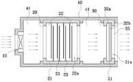
도 1은 본 발명의 바람직한 실시예에 의한 유해가스 및 악취 제거장치를 나타내는 모식도.
도 2는 본 발명의 다른 바람직한 실시예에 의한 유해가스 및 악취 제거장치를 나타내는 모식도.
도 3은 본 발명의 다른 바람직한 실시예에 의한 유해가스 및 악취 제거장치가 장착된 시약장을 나타내는 사시도.BRIEF DESCRIPTION OF THE DRAWINGS FIG. 1 is a schematic view showing a harmful gas and odor removing apparatus according to a preferred embodiment of the present invention. FIG.
2 is a schematic diagram showing an apparatus for removing harmful gas and odor according to another preferred embodiment of the present invention.
3 is a perspective view showing a reagent box equipped with an apparatus for removing harmful gas and odor according to another preferred embodiment of the present invention.
본 발명은 공기 중에 포함된 유해가스 또는 악취를 유발물질 등과 같은 오염물질을 제거하여 깨끗한 공기로 정화하는 유해가스 및 악취 제거장치에 관한 것으로서, 유해가스 또는 악취가 포함된 오염된 공기를 함체(40)의 내부공간(41)으로 유입시키는 송풍부재(10); 상기 함체(40)의 내부공간(41)에 구비되고, 이온클러스터를 생성시켜 오염된 공기에 포함된 오염물질을 산화시켜 제거하는 이온클러스터 생성모듈(20) 및; 상기 함체(40)의 내부공간(41)에 구비되고, 제올라이트계 규산염 수화물의 흡착필터(32)를 구비하며, 상기 이온클러스터 생성모듈(20)을 통과한 공기를 유입받아 공기에 포함된 미제거된 오염물질을 제거하는 필터링모듈(30);을 포함하여 구성되는 유해가스 및 악취 제거장치에 관한 것이다.The present invention relates to a harmful gas and odor removing apparatus for removing harmful gas or odor contained in air by removing pollutants such as inducing substances and purifying the polluted air with clean air, A blowing
이하 본 발명의 실시예를 도시한 도면 1 내지 3을 참고하여 본 발명을 구체적으로 설명하면 다음과 같다.
DETAILED DESCRIPTION OF THE PREFERRED EMBODIMENTS The present invention will now be described more fully hereinafter with reference to the accompanying drawings, in which preferred embodiments of the invention are shown.
우선, 본 발명에 의한 유해가스 및 악취 제거장치를 통하여 정화되는 공기는 실내공기, 산업 배기가스, 자동차 배기가스 또는 시약장 내부공기 등이 해당될 수 있고, 오염물질은 포름알데히드, 아세트알데히드, 벤젠, 톨루엔, 메탄 또는 암모니아 등과 같은 휘발성 유기 화합물(Volatile Oganic Compound), 곰팡이, 세균, 진균, 박테리아 또는 황화수소, 메르캅탄류, 아민 등 기타 자극성 있어 후각에 불쾌감과 혐오감을 주는 자극성 물질 등이 포함된다.
First, the air to be purified through the apparatus for removing noxious gas and odor according to the present invention may be indoor air, industrial exhaust gas, automobile exhaust gas or air inside a reagent room, and pollutants may be formaldehyde, acetaldehyde, benzene, Volatile organic compounds such as benzene, toluene, methane or ammonia, fungi, bacteria, fungi, bacteria or hydrogen sulfide, mercaptans, amines and other stimulants and irritating substances that cause discomfort and disgust in the olfactory sense.
구체적으로, 상기 송풍부재(10)는 유해가스 또는 악취가 포함된 오염된 공기를 함체(40)의 내부공간(41)으로 유입시키는 구성으로서, 오염된 공기 및 오염물질이 제거된 공기에 대한 이송력을 제공하는 구성이다.Specifically, the
즉, 상기 함체(40)는 송풍부재(10), 이온클러스터 생성모듈(20) 및 필터링모듈(30) 순차적으로 장착시키고, 외부공간과 내부공간(41)을 분리시키는 구성이다. 즉, 함체(40)의 일측에 형성된 흡입구를 통하여 내부공간(41)으로 오염된 공기를 유입받고, 유입된 공기가 내부공간(41)에 구비된 이온클러스터 생성모듈(20)을 순차적으로 통과될 수 있도록 하여, 공기에서 오염물질이 제거될 수 있도록 하는 구성이다.That is, the
이때, 함체(40)의 타측에는 필터링모듈(30)을 통과한 공기가 함체(40)의 외부로 배출될 수 있도록 하는 배출구가 구비되고, 상기 흡입구과 배출구 이외의 함체(40) 부분은 밀폐되어 외부공기와 내부공기가 혼합되지 않도록 구성된다.At this time, the other side of the
또한 송풍부재(10)는 일반적인 송풍팬을 이용할 수도 있으나, 인버터 방식의 송풍팬을 이용하는 것이 바람직하다. 즉, 인버터 방식의 송풍팬은 공기 중에 오염물질이 다량 포함된 경우에는 송풍팬의 회전속도를 빠르게 조절하여 함체(40)의 내부공간(41)으로 오염물질이 포함된 공기의 유입량을 증가시키고, 공기 중에 오염물질이 소량 포함된 경우에는 송풍팬의 회전속도를 느리게 조절하여 함체(40)의 내부공간(41)으로의 공기 유입량을 감소시키도록 구성될 수 있다.The blowing
상기와 연관하여, 인버터 방식의 송풍팬의 회전속도를 조절하기 위한 오염물질 농도 센싱을 위한 센서 및 센서의 신호를 전달받아 송풍팬에 회전속도 조절 신호를 전달하는 제어부는 일반적인 기술을 적용가능함은 자명할 것이다.In connection with the above, it is possible to apply a general technology to a control unit for receiving a signal of a sensor for sensing the pollutant concentration for controlling the rotation speed of the blowing fan of the inverter type and a sensor for transmitting the rotational speed adjusting signal to the blowing fan something to do.
아울러 송풍부재(10)는 함체(40)의 유입구 또는 유입구에 인접된 부분에 구비되고, 필요에 따라 함체(40)의 배출구에 상기 송풍부재(10)와 동일한 기능을 가지는 또 다른 송풍부재(미도시)가 더 구비되어 정화된 공기가 빠르게 함체(40)의 외부로 배출될 수 있거나 자체 순환될 수 있도록 구성할 수 있다.
The
또한 이온클러스터 생성모듈(20)은 상기 함체(40)의 내부공간(41)에 구비되고, 이온클러스터를 생성시켜 오염된 공기에 포함된 오염물질을 산화시켜 제거하는 구성으로서, 공기 중에 포함된 오염물질 분자를 분해시키는 이온클러스터를 생성시키는 구성이다.The ion
구체적으로, 이온 클러스터(Ion Cluster)는 일반적으로 산소분자 이온 약1~60개가 모인 집합체를 말하는 것으로서, 본 발명에 있어서는 산소양이온, 산소음이온, 수산화기 및 과산화기를 포함하는 것이다.Specifically, an ion cluster generally refers to an aggregate in which about 1 to 60 molecular oxygen ions are collected. In the present invention, the ion cluster includes oxygen anion, oxygen anion, hydroxyl group, and peroxide.
즉, 상기 이온클러스터 생성모듈(20)에 구비되는 방전부재(22)는 방전부재(22)의 유전체 표면에 강한 전기장을 형성시키고, 형성된 전기장에 의하여 발생된 방전은 공기 중에 포함된 산소분자에 에너지를 가하여 산소분자에서 전자를 빼앗아 산소이온을 만들거나 이온화된 산소를 서로 결합시켜 부산물인 오존을 만든다.That is, the
이때, 방전부재(22)의 방전에 의하여 생성된 산소음이온은 공기 중의 수증기와 반응하여 수산화기 및 과산화기를 생성하고, 부산물인 오존과 반응하여 수산화기를 생성한다.At this time, the oxygen anion generated by the discharge of the
더불어 상기와 같이 생성된 산소양이온, 산소음이온, 수산화기 및 과산화기는 이온클러스터의 상태로 집합되고, 불안정한 상태이기 때문에 강력한 친화력을 가져 오염물질을 분해하는 작용을 한다.In addition, the oxygen cations, oxygen anions, hydroxyl groups, and peroxide groups generated as described above collect in the state of ion clusters and are in an unstable state, so that they have a strong affinity to decompose contaminants.
즉, 오염물질 중 하나인 휘발성 유기 화합물 또는 악취를 유발하는 자극성 물질은 하기의 반응식과 같은 반응을 통하여 이온클러스터에 의하여 직접 분해된다.That is, a volatile organic compound, which is one of pollutants, or a stimulant that generates odor is directly decomposed by ion clusters through the reaction as shown in the following reaction formula.
[반응식 1][Reaction Scheme 1]

또한 이온클러스터의 수산화기는 곰팡이, 세균, 진균 또는 박테리아 등은 세포막에 있는 수소를 빼앗아 물(H2O)로 전환되고, 수소를 제거당한 곰팡이, 세균, 진균 또는 박테리아의 세포는 세포막이 파괴되기 때문에 비활성화되어 무해한 물질로 전환된다.
In addition, hydroxyl groups of ion clusters such as fungi, bacteria, fungi or bacteria are converted into water (H2 O) by depriving the cell membrane of hydrogen and the cells of fungi, bacteria, fungi, It is inactivated and converted into a harmless substance.
아울러 본 발명에 의한 이온클러스터 생성모듈(20)은 유전체가 구비된 방전부재(22)를 포함하는 구성이면 어떠한 구성을 하여도 무방하나, 외부에서 전원을 공급받아 자기장을 형성하는 유전체를 구비하는 방전부재(22)를 포함하여야 한다.In addition, the ion
보다 상세하면, 본 발명에 의한 이온클러스터 생성모듈(20)은 일측은 오염된 공기를 유입받는 흡입구가 형성되고, 타측에는 오염물이 제거된 공기를 배출하는 배출구가 형성되며, 내부에 내부공간(22a)이 형성된 하우징(21); 고전압 전원과 저전압 전원이 각각 공급될 수 있도록 한 쌍의 유전체판(23)으로 구성되되, 상기 한 쌍의 유전체판(23)은 복수 개가 서로 이격되어 하우징(21)의 내부공간(22a)에 장착되는 방전부재(22) 및; 상기 유전체판(23)에 고전압 전원과 저전압 전원을 공급하는 전원부재(미도시);를 포함하여 구성될 수 있다.More specifically, the ion
구체적으로, 상기 하우징(21)은 방전부재(22)를 지지하기 위한 구성으로서, 일측은 오염된 공기를 유입받는 흡입구가 형성되고, 타측에는 오염물이 제거된 공기를 배출하는 배출구가 형성되며, 내부에 내부공간(22a)이 형성된 구성이다.Specifically, the
이때, 하우징(21)의 일정부분은 함체(40)의 내부공간(41) 일정부분에 체결되고, 보다 바람직하게는 하우징(21)의 외측과 함체(40) 내부공간(41)의 내측 사이는 기밀되거나 내부공간(41)의 일정부분 자체가 내측으로 돌출되어 하우징(21)의 기능을 할 수도 있다.A certain portion of the
즉, 하우징(21)의 외측과 함체(40)의 내측은 닫혀 있어 오염된 공기가 하우징(21)의 내부공간(22a)으로만 이송될 수 있도록 구성된다.
That is, the outer side of the
또한 상기 구성의 이온클러스터 생성모듈(20)은 방전부재(22)에 구비된 유전체가 판상으로 구성되고, 상기 판상의 유전체(이하, '유전체판(23)'이라 칭함.)는 고전압 전원과 저전압 전원이 각각 공급될 수 있도록 한 쌍으로 구성되되, 어느 하나의 유전체판(23)과 다른 하나의 유전체판(23)은 서로 이격되어 전압차를 가지는 유전체판(23) 사이에서 방전이 일어날 수 있도록 구성되는 것이 바람직하다.In the ion
아울러 한 쌍의 유전체판(23)은 도 1과 같이 복수 개가 이격되는 상태로 연속되어 하우징(21)의 내부공간(22a)에 장착되는 구성을 한다.In addition, the pair of
이때, 유전체판(23)은 종래 관 형태로 구성된 방전관의 유전체 형태와 비교하여, 공기에 대한 노출 표면적이 넓기 때문에 방전시 공기 중에 포함된 오염물질의 분해능력을 향상시킬 수 있는 효과를 발휘한다.At this time, the
즉, 방전부재(22)는 고전압 전원과 저전압 전원이 각각 공급될 수 있도록 한 쌍의 유전체판(23)으로 구성되되, 상기 한 쌍의 유전체판(23)은 복수 개가 서로 이격되어 하우징(21)의 내부공간(22a)에 장착되는 구성을 한다.That is, the
아울러 유전체판(23)은 유전체판(23)에 인가되는 전원에 의하여 강한 전기장을 형성할 수 있는 재질의 것이면 어떠한 종류의 것을 이용할 수 있으나, MgO, Al2O3, TiO2, SiO2, Pb(Zr,Ti)O3, Si3N4, 또는 PZT 등의 산화물이나 PTFE, Teflon, ABS, PEEK, PC, 또는 PVE 등의 엔지니어링 플라스틱을 사용하는 것이 바람직하다. 또한, 유전체에 부착된 고전압 전극에 전도성 재료를 코팅하거나, 유전체에 바로 코팅하여 전극으로 사용할 수도 있다.The
또한, 유전체판(23)의 표면에 코팅할 경우, 백금, 텅스텐 또는 은 중 어느 하나 이상의 금속 재질의 방전물질을 0.1~5㎛의 두께로 코팅하여 방전효과를 향상시킬 수 있다.When the surface of the
즉, 종래 이온클러스터 생성장치의 방전관은 대부분 약 4kv 전압의 전원을 인가시켜 방전을 유도하지만, 상기와 같이 방전물질의 표면에 코팅된 유전체판(23)은 전원의 인가시에 더욱 강한 전기장을 형성시킬 수 있는 효과를 발휘하기 때문에 유전체판(23)에 인가되는 전원의 전압을 약 1.5~2.5kv 전압의 전원으로 낮출 수 있는 효과를 실현하고, 방전시에 생성되는 오존의 양을 줄일 수 있는 효과를 실현한다.That is, the discharge tube of the conventional ion cluster generating apparatus induces the discharge by applying a voltage of about 4 kV. However, the
구체적으로, 한 쌍의 유전체판(23) 각각에 인가되는 고전압의 전원과 저전압의 전원에 의하여 유전체판(23)에 형성되는 전기장은 유전체판(23)의 재질에 따라 일정하게 정하여진 에너지를 가지게 된다. 이에 대하여 유전체판(23)에 방전물질이 코팅된 경우에는 유전체의 분극 현상을 더욱 극대화시키는 효과를 발휘하여 유전체판(23)에 형성되는 전기장의 세기를 증가시키는 효과를 발휘하고, 결과적으로는 한 쌍의 유전체판(23)에서 생성되는 방전의 세기를 증가시는 효과를 발휘한다.Specifically, the electric field formed on the
또한 전원부재는 상기 유전체판(23)에 고전압 전원과 저전압 전원을 공급하는 구성으로서, 일반적인 전원공급장치와 전원공급장치와 연결된 전원라인으로 구성가능하다. 더불어 전원라인은 병렬 또는 직렬로 복수 개의 유전체판(23) 각각에 고전워 전원 및 저전압 전원을 각각 공급할 수 있도록 구성된다.The power supply member is configured to supply a high-voltage power supply and a low-voltage power supply to the
또한 서로 인접되는 상태로 이격된 어느 하나의 유전체판(23) 한 쌍과 다른 하나의 유전체판(23) 한 쌍의 사이에는 방전차단 중간체(미도시)가 구비되어, 방전이 한 쌍의 유전체판(23) 사이에만 일어나고 인접된 어느 하나의 유전체판(23) 한 쌍과 다른 하나의 유전체판(23) 한 쌍의 사이에서는 일어나지 않도록 구성되는 것이 바람직하다.Further, a discharge preventing intermediate (not shown) is provided between a pair of one
이때, 상기 방전차단 중간체는 수정 또는 유리 등의 부도체로 구성되어 어느 하나의 유전체판(23) 한 쌍 사이에서 일어나야할 방전이 인접된 다른 하나의 유전체판(23) 한 쌍 중의 유전체판(23)과 일어나지 않도록 구성되는 것이 바람직하다.At this time, the discharge interrupting intermediate is composed of non-conductive materials such as quartz or glass, and discharges to be caused between a pair of
또한 방전차단 중간체는 서로 인접되는 상태로 이격된 어느 하나의 유전체판(23) 한 쌍과 다른 하나의 유전체판(23) 한 쌍의 사이에 위치될 수도 있고, 어느 하나의 유전체판(23) 한 쌍과 다른 하나의 유전체판(23) 한 쌍의 유전체판(23) 중 인접된 유전체판(23) 각각(또는 어느 하나의 유전체판(23))에 부착되는 형태로 위치될 수도 있다.Also, the discharge preventing intermediate may be disposed between a pair of one
아울러 오염물질을 포함하는 공기는 송풍부재(10)에 의한 이송력으로 하우징(21)의 내부공간(22a)으로 유입된 이후 방전부재(22)를 구성하는 한 쌍의 유전체판(23) 사이사이를 지나게 되고, 한 쌍의 유전체판(23) 사이에서 일어나는 방전으로서 생성된 이온 클러스터에 의하여 오염물질이 제거되게 된다.
The air containing the pollutants is introduced into the
또한 필터링모듈(30)은 상기 함체(40)의 내부공간(41)에 구비되고, 제올라이트계 규산염 수화물의 흡착필터(32)를 구비하며, 상기 이온클러스터 생성모듈(20)을 통과한 공기를 유입받아 공기에 포함된 미제거된 오염물질을 제거하는 구성으로서, 이온클러스터 생성모듈(20)에서 미제거된 오염물질을 선택적으로 제거하는 구성이다.The
즉, 상기 흡착필터(32)는 이온클러스터 생성모듈(20)에서 생성된 이온 클러스터에 의하여 미분해된 오염물질을 물리적 흡착방식으로 제거하기 위한 구성으로서, 제올라이트계 규산염 수화물을 포함하는 필터로 구성된다.That is, the
또한 흡착필터(32)는 제올라이트계 규산염 수화물만으로 제조된 것을 이용할 수도 있고, 부직포와 같은 지지체에 제올라이트계 규산염 수화물이 코팅 또는 부착된 것을 이용할 수 있다.The
이때, 흡착필터(32)가 제올라이트계 규산염 수화물을 열압착 성형한 것으로 만들어지는 경우에는, 필터링모듈(30)에 구비된 흡착필터(32)를 사용한 후 흡착필터(32)만을 열처리하여 흡착필터(32)의 세공에 흡착된 오염물질 입자를 산화시켜 제거하고, 오염물질이 제거된 흡착필터(32)를 다시 필터링모듈(30)에 장착하여 재사용할 수 있도록 하는 효과를 발휘한다.At this time, when the
아울러 상기 필터링모듈(30)은 제올라이트계 규산염 수화물의 흡착필터(32)를 구비하는 구성이면 다양한 다른 구성들과 결합되는 구성을 하여도 무방하나, 일측은 오염된 공기를 유입받는 흡입구(3)가 형성되고, 타측에는 오염물이 제거된 공기를 배출하는 배출구(3)가 형성되며, 내부에 내부공간(31a)이 형성된 케이스(31)와; 상기 케이스(31)의 내부공간(31a)에 내재되는 제올라이트계 규산염 수화물의 흡착필터(32);를 포함하는 구성을 할 수 있다.In addition, the
즉, 상기 케이스(31)는 이온클러스터 생성모듈(20)의 하우징(21)과 같은 역할을 하는 구성으로서, 흡착필터(32)를 함체(40)의 내부공간(41)에 지지시키기 위한 구성이다.That is, the case 31 has the same structure as the
구체적으로, 케이스(31)이 일측에 형성된 흡입구(3)는 이온클러스터 생성모듈(20)에서 1차적으로 정화되었으나 미제거된 오염물질을 포함하는 공기를 유입받는 구성이고, 타측에 형성된 배출구(3)는 케이스(31)의 내부공간(31a)에 구비된 흡착필터(32)에 의하여 오염물질이 제거된 공기를 케이스(31)의 외부로 배출하는 구성이다. 이때, 케이스(31)의 배출구(3)는 함체(40)의 배출구와 동일한 위치에 구성될 수도 있다.Specifically, the inlet port 3 formed on one side of the case 31 is configured to receive air containing contaminants that have been cleaned primarily by the ion
또한 케이스(31)의 일정부분은 함체(40)의 내부공간(41) 일정부분에 체결되고, 보다 바람직하게는 케이스(31)의 외측과 함체(40) 내부공간(41)의 내측 사이는 기밀되거나 함체(40)의 내부공간(41) 일정부분 자체가 내측으로 돌출되어 케이스(31)의 기능을 할 수도 있다.A certain portion of the case 31 is fastened to a certain portion of the
즉, 케이스(31)의 외측과 함체(40)의 내측은 닫혀 있어 오염된 공기가 케이스(31)의 내부공간(31a)으로만 이송될 수 있도록 구성된다.
That is, the outside of the case 31 and the inside of the
아울러 케이스(31)의 내부공간(31a)에 내재되는 형태로 구비되는 흡착필터(32)에 포함되는 제올라이트계 규산염 수화물은 제올라이트계 규산염 수화물의 종류에 따라 다양한 구조와 세공의 크기를 가지고, 본 발명에 있어서는 유해가스 및 악취 제거장치를 이용하여 제거하기 위한 오염물질의 종류에 따라 다양한 종류의 것으로 구성가능하다.The zeolite-based silicate hydrate included in the
즉, 제올라이트계 규산염 수화물은 흡착성, 흡습성 또는 양이온 교환성 등의 특징이 있고, 본 발명에 있어서는 오염물질 입자를 제올라이트계 규산염 수화물의 세공에 흡착가능한 성질을 이용하며, 오염물질의 종류에 따라서는 달라지는 오염물질 입자의 크기에 따라 구조 및 세공의 크기가 다른 제올라이트계 규산염 수화물을 이용할 수 있다.That is, the zeolite-based silicate hydrate has characteristics such as adsorptivity, hygroscopicity, or cation exchangeability, and in the present invention, the property of adsorbing the contaminant particles to the pores of the zeolite-based silicate hydrate is utilized, Depending on the size of the contaminant particles, zeolite-based silicate hydrates having different structures and pore sizes can be used.
또한 제올라이트계 규산염 수화물의 표면(세공을 포함함.)에 노출되는 수산화기와 같은 작용기를 금속으로 치환한 제올라이트계 규산염 수화물을 이용하여 오염물질을 선택적으로 흡착할 수도 있다.In addition, zeolite-based silicate hydrate in which a functional group such as a hydroxyl group exposed to the surface (including pores) of a zeolite-based silicate hydrate is substituted with a metal may be used to selectively adsorb a contaminant.
구체적으로, 본 발명에 있어서의 제올라이트계 규산염 수화물의 수산화기와 같은 작용기를 Cu, Co, Fe, Ni 또는 Zn으로 치환한 경우, 제올라이트계 규산염 수화물의 세공의 크기를 줄이는 효과와 상기 종류의 치환 금속 입자에 대한 흡착성이 높은 오염물질 입자에 대한 흡착성을 향상시킬 수 있는 효과를 실현가능하다.Specifically, when the functional group such as the hydroxyl group of the zeolite-based silicate hydrate of the present invention is substituted with Cu, Co, Fe, Ni or Zn, the effect of reducing the size of the pores of the zeolitic silicate hydrate, It is possible to realize the effect of improving the adsorptivity to the contaminant particles having a high adsorption property.
아울러 본 발명에 의한 유해가스 및 악취 제거장치를 시약장과 같은 장치에 장착하는 경우에는 제올라이트계 규산염 수화물은 포자사이트(faujasite, FAU), 캐버자이트(chabazite, CHA) 또는 페리어라이트(ferrierite, FER) 구조 유형을 가지는 것을 이용할 수 있다.In addition, when the apparatus for removing noxious gas and odor according to the present invention is installed in a device such as a reagent station, the zeolite-based silicate hydrate may contain faujasite (FAU), chabazite (CHA) or ferrierite ) Structure type can be used.
포자사이트형 제올라이트로는 치환 또는 미치환의 제올라이트 X, Y, 및 SAPO-37 중 어느 하나를 사용할 수 있으며, 캐버자이트형 제올라이트로는 치환 또는 미치환의 AlPO-34, CoAPO-44, CoAPO-47, SAPO-34, 및 SAPO-47 중 어느 하나를 사용할 수 있으며, 페리어라이트형 제올라이트로는 치환 또는 미치환의 ZSM-35, NU-23 중 어느 하나를 사용할 수 있다.As the spore-forming zeolite, any one of substituted or unsubstituted zeolites X, Y and SAPO-37 can be used. As the zeolite having a chabazite structure, substituted or unsubstituted AlPO-34, CoAPO-44, CoAPO-47 SAPO-34 and SAPO-47 can be used. As the ferrierite type zeolite, any of ZSM-35 and NU-23 which is substituted or unsubstituted can be used.
일예로 시약장에 포함된 공기는 다양한 종류의 약에 포함된 유기성분이 다양하게 포함되고, 상기 약에 포함된 유기성분의 입자크기 역시 다양하기 때문에 구조밀도(Framework density) 높고 세공(셀)의 크기가 작은 상기 구조 유형의 제올라이트계 규산염 수화물을 이용하는 것이 바람직하다.For example, the air contained in the reagent contains a variety of organic components contained in various kinds of drugs, and since the particle size of the organic component contained in the drug is various, the structure density is high and the size of the pores It is preferable to use zeolite-based silicate hydrate of the above-mentioned structure type.
또한 포자사이트(faujasite, FAU), 캐버자이트(chabazite, CHA) 또는 페리어라이트(ferrierite, FER) 구조 유형의 제올라이트계 규산염 수화물은 필터의 형태로 단독으로 만들어질 수도 있고, 어느 하나 이상 혼합된 제올라이트계 규산염 수화물이 필터의 형태로 만들어질 수도 있다.Also, zeolitic silicate hydrates of the faujasite (FAU), chabazite (CHA) or ferrierite (FER) structure types may be made solely in the form of filters, Zeolite-based silicate hydrates may be made in the form of filters.
더불어 본 발명은 도 2와 같이 상기 흡착필터(32)를 포자사이트(faujasite, FAU)형 또는 캐버자이트(chabazite, CHA)형의 1종 이상의 제올라이트계 규산염 수화물을 포함하는 제1흡착필터(32a)와; 상기 제1흡착필터(32a)에 적층되고, 페리어라이트(ferrierite, FER)형의 제올라이트계 규산염 수화물을 포함하는 제2흡착필터(32b);를 포함하도록 구성하여, 다층의 흡착필터(32)를 이용할 수도 있다.2, the
구체적으로, 상기 제1흡착필터(32a)와 제1흡착필터(32a)는 세공의 크기를 달리하는 방식으로 적층되어 단일의 흡착필터(32)로 만들어지는 구성으로서, 제1흡착필터(32a)를 구성하는 포자사이트형의 제올라이트계 규산염 수화물은 3차원 세공구조로서 대략 7~8Å 정도의 세공을 가지고 있으며, 캐버자이트형의 제올라이트계 규산염 수화물은 3차원 세공구조로서 대략 7~8Å 정도의 세공(Cell) 크기를 가지기 때문에, 입자 크기가 상대적으로 큰 오염물질 입자를 흡착할 수 있는 효과를 가진다.Specifically, the
상기에 대하여, 페리어라이트형의 제올라이트계 규산염 수화물은 상기 포자사이트형 또는 캐버자이트형의 제올라이트계 규산염 수화물과 비교하여 2차원 구조를 가지고 있고, 또한, 상대적으로 작은 3~4Å 정도의 세공을 가지기 때문에, 입자 크기가 상대적으로 작은 오염물질 입자를 흡착할 수 있는 효과를 가진다.On the other hand, the ferrierite type zeolite-based silicate hydrate has a two-dimensional structure as compared with the spore-site type or chabazite-type zeolite-based silicate hydrate, and has a relatively small pore size of 3 to 4 Å Therefore, it has an effect of adsorbing contaminant particles having a relatively small particle size.
즉, 상기와 같이 흡착필터(32)가 제1흡착필터(32a)와 제2흡착필터(32b)로 구성되는 경우에는, 제1흡착필터(32a)가 이온클러스터 생성모듈(20) 방향에 위치되고 제2흡착필터(32b)가 함체(40)의 배출구 방향에 위치되도록 구성되어, 제1흡착필터(32a)를 통하여 입자크기가 큰 오염물질을 제거하고 제2흡착필터(32b)를 통하여 입자크기가 작은 오염물질을 제거할 수 있다.That is, when the
또한 제1흡착필터(32a)와 제2흡착필터(32b) 각각은 단독으로 열압착 성형되어 판상으로 만들어진 후 단독으로 케이스(31)에 장착되는 구성을 할 수도 있고, 상호 부착되어 단일의 흡착필터(32)로 구성될 수도 있으며, 제1흡착필터(32a) 또는 제2흡착필터(32b)의 어느 하나 이상의 면에 부직포와 같은 직물이 부착되어 흡착필터(32)의 강도를 보강하도록 구성될 수도 있다.Each of the
아울러 상기 케이스(31)의 배출구(3) 또는 배출구와 인접된 흡착필터(32)의 일면과 인접된 부분에는 헤파필터(33)(High efficiency particulate air filter, HEPA filter)가 더 구비되는 구성을 하여, 정화완료되어 함체(40)의 외부로 배출되는 공기에 포함되어 있을 수 있는 오염물질의 미세입자나 세균을 다시 한 번 제거할 수 있도록 할 수 있다.
A high efficiency particulate air filter (HEPA filter) 33 is further provided at a portion adjacent to one side of the
상기와 연관하여, 본 발명에 의한 유해가스 및 악취 제거장치는 블루투스 또는 와이파이 등과 같은 무선통신을 이용하여 통신 가능한 사용자단말기를 이용하여 제어가능한 구성을 할 수 있다.In connection with the above, the harmful gas and odor removing apparatus according to the present invention can be configured to be controllable using a user terminal capable of communicating using wireless communication such as Bluetooth or Wi-Fi.
즉, 상기 함체(40)의 내부공간(41) 또는 이온클러스터 생성모듈의 하우징(21) 내부공간(22a)에는 온도, 습도, 유해가스 또는 먼지 등의 인자를 측정할 수 있는 측정센서가 더 구비되고, 상기 측정센서에 의하여 감지된 인자 정보를 마이컴(Micom)이 전달받아 마이컴과 연결된 무선 송ㆍ수신기를 통하여 사용자단말기와 상기 인자 정보를 통신할 수 있다.That is, a measurement sensor capable of measuring factors such as temperature, humidity, noxious gas or dust is further provided in the
이때, 작업자는 스마트폰, 타블릿PC 또는 휴대단말기 등과 같은 사용자단말기를 이용하여 상기 온도, 습도, 유해가스 또는 먼지 등에 관한 인자 정보를 확인한 후, 상기 인자의 조절을 위한 제어명령을 내릴 수 있다.At this time, the operator can check the factor information on the temperature, humidity, noxious gas, dust or the like using a user terminal such as a smart phone, a tablet PC or a portable terminal, and then issue a control command for controlling the factor.
더불어 작업자에 의하여 내려진 제어명령은 사용자단말기를 통하여 무선 송ㆍ수신기로 전달되고, 무선 송ㆍ수신기와 연결된 마이컴에서 제어명령을 전달받아 함체(40)의 내부공간(41) 또는 이온클러스터 생성모듈의 하우징(21) 내부공간(22a)에 더 구비되는 온도조절기, 습도조절기, 이온클러스터 생성모듈의 전원부재 등의 구성에 제어명령을 내려, 온도, 습도 또는 유전체판(23)에 대한 전원량을 조절할 수 있다.In addition, the control command issued by the operator is transmitted to the wireless transceiver through the user terminal, and the control command is received from the microcomputer connected to the wireless transceiver. The control command is transmitted to the
또한 상기 마이컴에 온도, 습도, 유해가스 또는 먼지 등에 관한 인자 조건을 일정하게 세팅된 경우, 유해가스 및 악취 제거장치의 가동 중 상기 인자 조건이 세팅된 인자 조건에 미달되거나 초과되면, 마이컴은 경고신호 정보를 사용자단말기에 전송하여 사용자가 미달되거나 초과된 인자 조건을 다시 조절할 수 있도록 구성될 수도 있다.
In addition, when the microcomputer is set to have a printing condition such as temperature, humidity, noxious gas, dust, or the like constantly, when the printing condition during the operation of the noxious gas or the malodor removing device is exceeded or exceeded, Information may be transmitted to the user terminal so that the user can adjust the under or over condition of the printing condition again.
다음은 본 발명에 의한 유해가스 및 악취 제거장치가 장착된 시약장의 내부공기를 정화시키는 과정에 대한 구체적인 실시예이다.The following is a specific example of the process of purifying the internal air of the reagent station equipped with the apparatus for removing noxious gas and odor according to the present invention.
우선, 시약장의 상부에는 유해가스 및 악취 제거장치가 장착되는 덕트가 구비되고, 덕트에는 시약장의 내부공간과 연통되는 흡입구가 형성되며 상기 덕트의 흡입구는 유해가스 및 악취 제거장치의 함체(40)에 형성된 흡입구와 연통된다.The duct is provided with a suction port communicating with the internal space of the reagent box. The suction port of the duct is connected to the
또한 함체(40)의 내부공간(41)에는 흡입구에 인접된 부분부터 배출구 방향으로 송풍부재(10), 이온클러스터 생성모듈(20) 및 필터링 모듈(30)이 순차적으로 구비된다.In addition, in the
구체적으로, 송풍부재(10)인 인버터 방식의 송풍팬의 작동에 의하여 시약장 내부에 내재된 다양한 약성분 입자가 포함된 공기는 덕트의 흡입구로 유입되고, 유입된 공기는 함체(40) 내부공간(41)에 내재된 이온클러스터 생성모듈(20)의 하우징(21)의 내부공간(22a)으로 유입된다.Specifically, by the operation of the blowing fan of the inverter type, which is the blowing
이때, 전원부재는 전원을 방전부재(22)의 유전체판(23, MgO의 재질로 만들어지고, 유전체판(23)의 표면에는 1㎛의 평균 두께로 백금 코팅이 되어 있는 상태임.)으로 인가하여 한 쌍씩 구분된 유전체판(23) 사이에서 방전이 일어나도록 하고, 약성분 입자가 포함된 공기는 복수 개의 격판 형태로 구분되어진 한 쌍씩 구분된 유전체판(23)의 사이사이로 유동되어 하우징(21)의 배출구 방향으로 유동되어 배출된다.At this time, the power source is supplied with power from the
상기와 같이 방전부재(22)를 상기와 같이 통과한 공기에 포함된 약성분 입자는 유기물이기 때문에 방전에 의하여 생성되는 이온클러스터에 의하여 1차적으로 분해되어 제거된다.Since the weak component particles included in the air passing through the
이후, 이온클러스터 생성모듈(20)의 하우징(21) 배출구로 배출된 공기는 함체(40)의 내부공간(41)에 말단 쪽에 구비된 필터링모듈(30)의 케이스(31) 내부공간(31a)로 유입되고, 케이스(31)의 내부공간(31a)에 내재된 흡착필터(케이스(31)의 흡입구 방향은 Co-제올라이트 Y로 만들어진 제1흡착필터(32a)가 위치되고, HZSM-35로 만들어진 제2흡착필터(32b)는 배출구 방향에 위치된 상태임.)를 통과하며, 이때 공기에 포함된 미량의 약성분 입자는 흡착필터(32)에 흡착되어 제거된다.The air discharged to the outlet of the
이후, 흡착필터(32)를 통과한 공기는 약성분이 모두 제거된 상태로 함체(40)의 배출구로 배출되어 시약장의 외부로 배출되거나, 시약장 내부에 형성된 덕트를 통하여 시약장 내부에서 자체 순환시킬 수 있다.
Thereafter, the air having passed through the
상기는 본 발명의 바람직한 실시예를 참고로 설명하였으며, 상기의 실시예에 한정되지 아니하고, 상기의 실시예를 통해 본 발명이 속하는 기술분야에서 통상의 지식을 가진 자가 본 발명의 요지를 벗어나지 않는 범위에서 다양한 변경으로 실시할 수 있는 것이다.
While the present invention has been particularly shown and described with reference to exemplary embodiments thereof, it is to be understood that the invention is not limited to the disclosed exemplary embodiments, but, on the contrary, It is possible to carry out various changes in the present invention.
10 : 송풍부재20 : 이온클러스터 생성모듈
21 : 하우징22a : 하우징의 내부공간
22 : 방전부재23 : 유전체판
30 : 필터링모듈31 : 케이스
31a : 케이스의 내부공간32 : 흡착필터
32a : 제1흡착필터32b : 제2흡착필터
33 : 헤파필터40 : 함체
41 : 함체의 내부공간10: air blowing member 20: ion cluster generating module
21:
22: discharge member 23: dielectric plate
30: Filtering module 31: Case
31a: inner space of the case 32: adsorption filter
32a:
33: HEPA filter 40: Enclosure
41: Internal space of the enclosure
Claims (6)
Translated fromKorean상기 함체(40)의 내부공간(41)에 구비되고, 이온클러스터를 생성시켜 오염된 공기에 포함된 오염물질을 산화시켜 제거하는 이온클러스터 생성모듈(20) 및;
상기 함체(40)의 내부공간(41)에 구비되고, 제올라이트계 규산염 수화물의 흡착필터(32)를 구비하며, 상기 이온클러스터 생성모듈(20)을 통과한 공기를 유입받아 공기에 포함된 미제거된 오염물질을 제거하는 필터링모듈(30);을 포함하여 구성되는 것을 특징으로 하는 유해가스 및 악취 제거장치.
An air blowing member (10) for introducing polluted air containing harmful gas or odor into the inner space (41) of the enclosure (40);
An ion cluster generation module 20 provided in the inner space 41 of the housing 40 for generating ion clusters to oxidize and remove contaminants contained in contaminated air;
And an adsorption filter 32 of zeolite-based silicate hydrate, which is provided in the inner space 41 of the housing 40. The air sucking filter 32 receives the air passing through the ion cluster generating module 20, And a filtering module (30) for removing the contaminants from the harmful gas and odor.
상기 이온클러스터 생성모듈(20)은,
일측은 오염된 공기를 유입받는 흡입구가 형성되고, 타측에는 오염물이 제거된 공기를 배출하는 배출구가 형성되며, 내부에 내부공간(22a)이 형성된 하우징(21);
고전압 전원과 저전압 전원이 각각 공급될 수 있도록 한 쌍의 유전체판(23)으로 구성되되, 상기 한 쌍의 유전체판(23)은 복수 개가 서로 이격되어 하우징(21)의 내부공간(22a)에 장착되는 방전부재(22) 및;
상기 유전체판(23)에 고전압 전원과 저전압 전원을 공급하는 전원부재;를 포함하여 구성되는 것을 특징으로 하는 유해가스 및 악취 제거장치.
The method according to claim 1,
The ion cluster generation module (20)
A housing (21) formed with an inlet for receiving polluted air on one side, an outlet for discharging polluted air from the other side, and an internal space (22a) formed therein;
A pair of dielectric plates 23 are mounted on the inner space 22a of the housing 21 such that a plurality of the dielectric plates 23 are spaced apart from each other and a high voltage power source and a low voltage power source are respectively supplied to the pair of dielectric plates 23. [ (22);
And a power source for supplying a high voltage power source and a low voltage power source to the dielectric plate (23).
상기 유전체판(23)은,
MgO, Al2O3, TiO2, SiO2, Pb(Zr,Ti)O3, Si3N4, PZT, PTFE, Teflon, ABS, PEEK, PC, 또는 PVE 중 어느 하나 이상의 재질의 것으로 구성되는 것을 특징으로 하는 유해가스 및 악취 제거장치.
3. The method of claim 2,
The dielectric plate (23)
And is made of at least one of MgO, Al2 O3 , TiO2 , SiO2 , Pb (Zr, Ti) O3 , Si3 N4 , PZT, PTFE, Teflon, ABS, PEEK, PC, And the harmful gas and odor removing device.
상기 유전체판(23)의 표면에는,
백금, 텅스텐 또는 은 중 어느 하나 이상의 금속 재질의 방전물질이 0.1~5㎛의 두께로 코팅되도록 구성되는 것을 특징으로 하는 유해가스 및 악취 제거장치.
3. The method of claim 2,
On the surface of the dielectric plate 23,
Wherein a discharge material of at least one of metal, platinum, tungsten, and silver is coated to a thickness of 0.1 to 5 占 퐉.
상기 필터링모듈(30)은,
일측은 오염된 공기를 유입받는 흡입구가 형성되고, 타측에는 오염물이 제거된 공기를 배출하는 배출구가 형성되며, 내부에 내부공간(31a)이 형성된 케이스(31)와;
상기 케이스(31)의 내부공간(31a)에 내재되는 제올라이트계 규산염 수화물의흡착필터(32);를 포함하여 구성되는 것을 특징으로 하는 유해가스 및 악취 제거장치.
The method according to claim 1,
The filtering module (30)
A case 31 having an inlet formed at one side thereof to receive contaminated air and an outlet for discharging air from which contaminants have been removed at the other side and having an internal space 31a therein;
A zeolite-based silicate hydrate contained in the inner space 31a of the case 31 And an adsorption filter (32) for adsorbing harmful gas and odor.
상기 흡착필터(32)는,
포자사이트(faujasite, FAU) 구조 유형 또는 캐버자이트(chabazite, CHA) 유형의 1종 이상의 제올라이트계 규산염 수화물을 포함하는 제1흡착필터(32a)와;
상기 제1흡착필터(32a)에 적층되고, 페리어라이트(ferrierite, FER) 구조 유형의 제올라이트계 규산염 수화물을 포함하는 제2흡착필터(32b);를 포함하여 구성되는 것을 특징으로 하는 유해가스 및 악취 제거장치.
6. The method of claim 5,
The adsorption filter (32)
A first adsorption filter 32a comprising at least one zeolitic silicate hydrate of the faujasite (FAU) structure type or the chabazite (CHA) type;
And a second adsorption filter (32b) stacked on the first adsorption filter (32a) and comprising zeolite-based silicate hydrate of ferrierite (FER) structure type. Odor removal device.
Priority Applications (1)
| Application Number | Priority Date | Filing Date | Title |
|---|---|---|---|
| KR1020150119329AKR20170024279A (en) | 2015-08-25 | 2015-08-25 | Apparatus for removing noxious gas and offensive odor |
Applications Claiming Priority (1)
| Application Number | Priority Date | Filing Date | Title |
|---|---|---|---|
| KR1020150119329AKR20170024279A (en) | 2015-08-25 | 2015-08-25 | Apparatus for removing noxious gas and offensive odor |
Publications (1)
| Publication Number | Publication Date |
|---|---|
| KR20170024279Atrue KR20170024279A (en) | 2017-03-07 |
Family
ID=58411577
Family Applications (1)
| Application Number | Title | Priority Date | Filing Date |
|---|---|---|---|
| KR1020150119329ACeasedKR20170024279A (en) | 2015-08-25 | 2015-08-25 | Apparatus for removing noxious gas and offensive odor |
Country Status (1)
| Country | Link |
|---|---|
| KR (1) | KR20170024279A (en) |
Cited By (5)
| Publication number | Priority date | Publication date | Assignee | Title |
|---|---|---|---|---|
| KR102146200B1 (en)* | 2019-10-14 | 2020-08-19 | 배준형 | high density fusion plasma sterilization and deodorizer |
| KR20210044141A (en)* | 2019-10-14 | 2021-04-22 | 배준형 | high density fusion plasma sterilization and deodorizer |
| CN114471045A (en)* | 2022-02-14 | 2022-05-13 | 山东绿立冠环保科技有限公司 | Waste gas dust removal adsorbs processing apparatus |
| KR20240061032A (en)* | 2022-10-31 | 2024-05-08 | 이민수 | Closed circulation reagent cabinet with improved acid resistance |
| KR20250112419A (en) | 2024-01-17 | 2025-07-24 | 주식회사 대진바이오 | Filter housing for removing the smeel of chemcals and a method for discharging the smell using it |
Citations (2)
| Publication number | Priority date | Publication date | Assignee | Title |
|---|---|---|---|---|
| KR200343312Y1 (en) | 2003-12-03 | 2004-02-27 | 주식회사 랩죤 | Toxic Reagent Storage Cabinet Using The Zeolite Filter |
| KR100959634B1 (en) | 2010-02-19 | 2010-05-27 | (주)지오필테크 | Air purification apparatus |
- 2015
- 2015-08-25KRKR1020150119329Apatent/KR20170024279A/ennot_activeCeased
Patent Citations (2)
| Publication number | Priority date | Publication date | Assignee | Title |
|---|---|---|---|---|
| KR200343312Y1 (en) | 2003-12-03 | 2004-02-27 | 주식회사 랩죤 | Toxic Reagent Storage Cabinet Using The Zeolite Filter |
| KR100959634B1 (en) | 2010-02-19 | 2010-05-27 | (주)지오필테크 | Air purification apparatus |
Cited By (5)
| Publication number | Priority date | Publication date | Assignee | Title |
|---|---|---|---|---|
| KR102146200B1 (en)* | 2019-10-14 | 2020-08-19 | 배준형 | high density fusion plasma sterilization and deodorizer |
| KR20210044141A (en)* | 2019-10-14 | 2021-04-22 | 배준형 | high density fusion plasma sterilization and deodorizer |
| CN114471045A (en)* | 2022-02-14 | 2022-05-13 | 山东绿立冠环保科技有限公司 | Waste gas dust removal adsorbs processing apparatus |
| KR20240061032A (en)* | 2022-10-31 | 2024-05-08 | 이민수 | Closed circulation reagent cabinet with improved acid resistance |
| KR20250112419A (en) | 2024-01-17 | 2025-07-24 | 주식회사 대진바이오 | Filter housing for removing the smeel of chemcals and a method for discharging the smell using it |
Similar Documents
| Publication | Publication Date | Title |
|---|---|---|
| CN108568213B (en) | Bench type laboratory air pollutant removing machine | |
| KR102198329B1 (en) | Combined sterilization air purifier | |
| CN103702690B (en) | Air purifier using electric field regeneration | |
| DK2806903T3 (en) | A mobile disinfection device to disinfect a given facility or equipment and a method of using that device | |
| KR20170024279A (en) | Apparatus for removing noxious gas and offensive odor | |
| CN103272445B (en) | Air purification equipment | |
| KR20120138500A (en) | Reclamated air cleaner using plasma | |
| US20230355823A1 (en) | Device for generating hydroxyl radicals | |
| US12303623B2 (en) | Apparatus for inactivation of airborne pathogens | |
| CN201796584U (en) | An air disinfection and purification media machine | |
| CN103398423A (en) | Air purifier | |
| KR20180076960A (en) | electric dust collector apparatus having moisture eliminator | |
| JP2005342142A (en) | Air purifier and air conditioner using the same | |
| CN209576189U (en) | A kind of filter core and the air purifier with the filter core | |
| CN209776105U (en) | vehicle air purifier convenient to carry | |
| CN208627022U (en) | Table type Laboratory air pollutant removal machine | |
| CN202546953U (en) | Fan pipe disc type plasma purifying and disinfecting device | |
| CN110925926A (en) | Computer room air purification system | |
| CN202747489U (en) | Medical air purification and disinfection device | |
| CN111821501A (en) | Low-temperature plasma sterilization and purification method | |
| JP5633759B2 (en) | Air cleaning apparatus and air cleaning method | |
| CN203907865U (en) | Solar air conditioner | |
| JP2010240630A (en) | Deodorization apparatus | |
| KR101570220B1 (en) | Ion cluster type portable local ventilation system | |
| CN204043078U (en) | The clarifier of a kind of ozone, photocatalyst, clean ion, ultraviolet, carbon geode |
Legal Events
| Date | Code | Title | Description |
|---|---|---|---|
| A201 | Request for examination | ||
| PA0109 | Patent application | Patent event code:PA01091R01D Comment text:Patent Application Patent event date:20150825 | |
| PA0201 | Request for examination | ||
| E902 | Notification of reason for refusal | ||
| PE0902 | Notice of grounds for rejection | Comment text:Notification of reason for refusal Patent event date:20160730 Patent event code:PE09021S01D | |
| E902 | Notification of reason for refusal | ||
| PE0902 | Notice of grounds for rejection | Comment text:Notification of reason for refusal Patent event date:20161028 Patent event code:PE09021S01D | |
| PG1501 | Laying open of application | ||
| E902 | Notification of reason for refusal | ||
| PE0902 | Notice of grounds for rejection | Comment text:Notification of reason for refusal Patent event date:20170413 Patent event code:PE09021S01D | |
| E601 | Decision to refuse application | ||
| PE0601 | Decision on rejection of patent | Patent event date:20170822 Comment text:Decision to Refuse Application Patent event code:PE06012S01D Patent event date:20170413 Comment text:Notification of reason for refusal Patent event code:PE06011S01I Patent event date:20161028 Comment text:Notification of reason for refusal Patent event code:PE06011S01I Patent event date:20160730 Comment text:Notification of reason for refusal Patent event code:PE06011S01I | |
| J201 | Request for trial against refusal decision | ||
| PJ0201 | Trial against decision of rejection | Patent event date:20170920 Comment text:Request for Trial against Decision on Refusal Patent event code:PJ02012R01D Patent event date:20170822 Comment text:Decision to Refuse Application Patent event code:PJ02011S01I Appeal kind category:Appeal against decision to decline refusal Appeal identifier:2017101004476 Request date:20170920 | |
| J301 | Trial decision | Free format text:TRIAL NUMBER: 2017101004476; TRIAL DECISION FOR APPEAL AGAINST DECISION TO DECLINE REFUSAL REQUESTED 20170920 Effective date:20190130 | |
| PJ1301 | Trial decision | Patent event code:PJ13011S01D Patent event date:20190130 Comment text:Trial Decision on Objection to Decision on Refusal Appeal kind category:Appeal against decision to decline refusal Request date:20170920 Decision date:20190130 Appeal identifier:2017101004476 |