KR20170017028A - Liquid crystal display device and manufacturing method thereof - Google Patents
Liquid crystal display device and manufacturing method thereofDownload PDFInfo
- Publication number
- KR20170017028A KR20170017028AKR1020150109933AKR20150109933AKR20170017028AKR 20170017028 AKR20170017028 AKR 20170017028AKR 1020150109933 AKR1020150109933 AKR 1020150109933AKR 20150109933 AKR20150109933 AKR 20150109933AKR 20170017028 AKR20170017028 AKR 20170017028A
- Authority
- KR
- South Korea
- Prior art keywords
- region
- drain electrode
- source electrode
- electrode
- drain
- Prior art date
- Legal status (The legal status is an assumption and is not a legal conclusion. Google has not performed a legal analysis and makes no representation as to the accuracy of the status listed.)
- Granted
Links
- 239000004973liquid crystal related substanceSubstances0.000titleabstractdescription55
- 238000004519manufacturing processMethods0.000titledescription19
- 239000004065semiconductorSubstances0.000claimsabstractdescription73
- 239000000758substrateSubstances0.000claimsabstractdescription27
- 238000005530etchingMethods0.000claimsdescription49
- 238000000034methodMethods0.000claimsdescription25
- 229920002120photoresistant polymerPolymers0.000claimsdescription22
- 239000010409thin filmSubstances0.000abstractdescription6
- 239000010408filmSubstances0.000description19
- 239000000463materialSubstances0.000description12
- 229910052751metalInorganic materials0.000description6
- 239000002184metalSubstances0.000description6
- 239000010936titaniumSubstances0.000description5
- VYPSYNLAJGMNEJ-UHFFFAOYSA-NSilicium dioxideChemical compoundO=[Si]=OVYPSYNLAJGMNEJ-UHFFFAOYSA-N0.000description4
- 238000005229chemical vapour depositionMethods0.000description4
- 239000010955niobiumSubstances0.000description4
- 229910052814silicon oxideInorganic materials0.000description4
- 230000000694effectsEffects0.000description3
- 239000011159matrix materialSubstances0.000description3
- 238000002161passivationMethods0.000description3
- BASFCYQUMIYNBI-UHFFFAOYSA-NplatinumChemical compound[Pt]BASFCYQUMIYNBI-UHFFFAOYSA-N0.000description3
- 229910052715tantalumInorganic materials0.000description3
- GUVRBAGPIYLISA-UHFFFAOYSA-Ntantalum atomChemical compound[Ta]GUVRBAGPIYLISA-UHFFFAOYSA-N0.000description3
- 229910052719titaniumInorganic materials0.000description3
- RTAQQCXQSZGOHL-UHFFFAOYSA-NTitaniumChemical compound[Ti]RTAQQCXQSZGOHL-UHFFFAOYSA-N0.000description2
- UMIVXZPTRXBADB-UHFFFAOYSA-NbenzocyclobuteneChemical compoundC1=CC=C2CCC2=C1UMIVXZPTRXBADB-UHFFFAOYSA-N0.000description2
- 239000011651chromiumSubstances0.000description2
- 229910052802copperInorganic materials0.000description2
- 239000010949copperSubstances0.000description2
- 230000005684electric fieldEffects0.000description2
- 239000011521glassSubstances0.000description2
- 239000010931goldSubstances0.000description2
- 239000011810insulating materialSubstances0.000description2
- 229910052750molybdenumInorganic materials0.000description2
- 229910052758niobiumInorganic materials0.000description2
- GUCVJGMIXFAOAE-UHFFFAOYSA-Nniobium atomChemical compound[Nb]GUCVJGMIXFAOAE-UHFFFAOYSA-N0.000description2
- 239000011669seleniumSubstances0.000description2
- 229910052709silverInorganic materials0.000description2
- 229910001316Ag alloyInorganic materials0.000description1
- 229910000838Al alloyInorganic materials0.000description1
- VYZAMTAEIAYCRO-UHFFFAOYSA-NChromiumChemical compound[Cr]VYZAMTAEIAYCRO-UHFFFAOYSA-N0.000description1
- RYGMFSIKBFXOCR-UHFFFAOYSA-NCopperChemical compound[Cu]RYGMFSIKBFXOCR-UHFFFAOYSA-N0.000description1
- 229910000881Cu alloyInorganic materials0.000description1
- XEEYBQQBJWHFJM-UHFFFAOYSA-NIronChemical compound[Fe]XEEYBQQBJWHFJM-UHFFFAOYSA-N0.000description1
- 229910001182Mo alloyInorganic materials0.000description1
- ZOKXTWBITQBERF-UHFFFAOYSA-NMolybdenumChemical compound[Mo]ZOKXTWBITQBERF-UHFFFAOYSA-N0.000description1
- 239000004642PolyimideSubstances0.000description1
- BUGBHKTXTAQXES-UHFFFAOYSA-NSeleniumChemical compound[Se]BUGBHKTXTAQXES-UHFFFAOYSA-N0.000description1
- BQCADISMDOOEFD-UHFFFAOYSA-NSilverChemical compound[Ag]BQCADISMDOOEFD-UHFFFAOYSA-N0.000description1
- NIXOWILDQLNWCW-UHFFFAOYSA-Nacrylic acid groupChemical groupC(C=C)(=O)ONIXOWILDQLNWCW-UHFFFAOYSA-N0.000description1
- 229910045601alloyInorganic materials0.000description1
- 239000000956alloySubstances0.000description1
- 229910052782aluminiumInorganic materials0.000description1
- XAGFODPZIPBFFR-UHFFFAOYSA-NaluminiumChemical compound[Al]XAGFODPZIPBFFR-UHFFFAOYSA-N0.000description1
- 229910021417amorphous siliconInorganic materials0.000description1
- QVGXLLKOCUKJST-UHFFFAOYSA-Natomic oxygenChemical compound[O]QVGXLLKOCUKJST-UHFFFAOYSA-N0.000description1
- 229910052804chromiumInorganic materials0.000description1
- 239000004020conductorSubstances0.000description1
- 238000001312dry etchingMethods0.000description1
- 239000007789gasSubstances0.000description1
- PCHJSUWPFVWCPO-UHFFFAOYSA-NgoldChemical compound[Au]PCHJSUWPFVWCPO-UHFFFAOYSA-N0.000description1
- 229910052737goldInorganic materials0.000description1
- 229910052735hafniumInorganic materials0.000description1
- VBJZVLUMGGDVMO-UHFFFAOYSA-Nhafnium atomChemical compound[Hf]VBJZVLUMGGDVMO-UHFFFAOYSA-N0.000description1
- 239000012535impuritySubstances0.000description1
- 238000011065in-situ storageMethods0.000description1
- 239000011733molybdenumSubstances0.000description1
- 229910052759nickelInorganic materials0.000description1
- 229910052760oxygenInorganic materials0.000description1
- 239000001301oxygenSubstances0.000description1
- 238000005240physical vapour depositionMethods0.000description1
- 239000004033plasticSubstances0.000description1
- 229910052697platinumInorganic materials0.000description1
- 230000010287polarizationEffects0.000description1
- 229910021420polycrystalline siliconInorganic materials0.000description1
- 229920001721polyimidePolymers0.000description1
- 239000002861polymer materialSubstances0.000description1
- VSZWPYCFIRKVQL-UHFFFAOYSA-Nselanylidenegallium;seleniumChemical compound[Se].[Se]=[Ga].[Se]=[Ga]VSZWPYCFIRKVQL-UHFFFAOYSA-N0.000description1
- 229910052711seleniumInorganic materials0.000description1
- 239000004332silverSubstances0.000description1
- 239000010944silver (metal)Substances0.000description1
- 238000004544sputter depositionMethods0.000description1
- 238000002834transmittanceMethods0.000description1
- WFKWXMTUELFFGS-UHFFFAOYSA-NtungstenChemical compound[W]WFKWXMTUELFFGS-UHFFFAOYSA-N0.000description1
- 229910052721tungstenInorganic materials0.000description1
- 239000010937tungstenSubstances0.000description1
Images


Classifications
- G—PHYSICS
- G02—OPTICS
- G02F—OPTICAL DEVICES OR ARRANGEMENTS FOR THE CONTROL OF LIGHT BY MODIFICATION OF THE OPTICAL PROPERTIES OF THE MEDIA OF THE ELEMENTS INVOLVED THEREIN; NON-LINEAR OPTICS; FREQUENCY-CHANGING OF LIGHT; OPTICAL LOGIC ELEMENTS; OPTICAL ANALOGUE/DIGITAL CONVERTERS
- G02F1/00—Devices or arrangements for the control of the intensity, colour, phase, polarisation or direction of light arriving from an independent light source, e.g. switching, gating or modulating; Non-linear optics
- G02F1/01—Devices or arrangements for the control of the intensity, colour, phase, polarisation or direction of light arriving from an independent light source, e.g. switching, gating or modulating; Non-linear optics for the control of the intensity, phase, polarisation or colour
- G02F1/13—Devices or arrangements for the control of the intensity, colour, phase, polarisation or direction of light arriving from an independent light source, e.g. switching, gating or modulating; Non-linear optics for the control of the intensity, phase, polarisation or colour based on liquid crystals, e.g. single liquid crystal display cells
- G02F1/133—Constructional arrangements; Operation of liquid crystal cells; Circuit arrangements
- G02F1/136—Liquid crystal cells structurally associated with a semi-conducting layer or substrate, e.g. cells forming part of an integrated circuit
- G02F1/1362—Active matrix addressed cells
- G02F1/1368—Active matrix addressed cells in which the switching element is a three-electrode device
- G—PHYSICS
- G02—OPTICS
- G02F—OPTICAL DEVICES OR ARRANGEMENTS FOR THE CONTROL OF LIGHT BY MODIFICATION OF THE OPTICAL PROPERTIES OF THE MEDIA OF THE ELEMENTS INVOLVED THEREIN; NON-LINEAR OPTICS; FREQUENCY-CHANGING OF LIGHT; OPTICAL LOGIC ELEMENTS; OPTICAL ANALOGUE/DIGITAL CONVERTERS
- G02F1/00—Devices or arrangements for the control of the intensity, colour, phase, polarisation or direction of light arriving from an independent light source, e.g. switching, gating or modulating; Non-linear optics
- G02F1/01—Devices or arrangements for the control of the intensity, colour, phase, polarisation or direction of light arriving from an independent light source, e.g. switching, gating or modulating; Non-linear optics for the control of the intensity, phase, polarisation or colour
- G02F1/13—Devices or arrangements for the control of the intensity, colour, phase, polarisation or direction of light arriving from an independent light source, e.g. switching, gating or modulating; Non-linear optics for the control of the intensity, phase, polarisation or colour based on liquid crystals, e.g. single liquid crystal display cells
- G02F1/133—Constructional arrangements; Operation of liquid crystal cells; Circuit arrangements
- G02F1/1333—Constructional arrangements; Manufacturing methods
- G02F1/133345—Insulating layers
- G—PHYSICS
- G02—OPTICS
- G02F—OPTICAL DEVICES OR ARRANGEMENTS FOR THE CONTROL OF LIGHT BY MODIFICATION OF THE OPTICAL PROPERTIES OF THE MEDIA OF THE ELEMENTS INVOLVED THEREIN; NON-LINEAR OPTICS; FREQUENCY-CHANGING OF LIGHT; OPTICAL LOGIC ELEMENTS; OPTICAL ANALOGUE/DIGITAL CONVERTERS
- G02F1/00—Devices or arrangements for the control of the intensity, colour, phase, polarisation or direction of light arriving from an independent light source, e.g. switching, gating or modulating; Non-linear optics
- G02F1/01—Devices or arrangements for the control of the intensity, colour, phase, polarisation or direction of light arriving from an independent light source, e.g. switching, gating or modulating; Non-linear optics for the control of the intensity, phase, polarisation or colour
- G02F1/13—Devices or arrangements for the control of the intensity, colour, phase, polarisation or direction of light arriving from an independent light source, e.g. switching, gating or modulating; Non-linear optics for the control of the intensity, phase, polarisation or colour based on liquid crystals, e.g. single liquid crystal display cells
- G02F1/133—Constructional arrangements; Operation of liquid crystal cells; Circuit arrangements
- G02F1/1333—Constructional arrangements; Manufacturing methods
- G02F1/1335—Structural association of cells with optical devices, e.g. polarisers or reflectors
- G02F1/133524—Light-guides, e.g. fibre-optic bundles, louvered or jalousie light-guides
- G—PHYSICS
- G02—OPTICS
- G02F—OPTICAL DEVICES OR ARRANGEMENTS FOR THE CONTROL OF LIGHT BY MODIFICATION OF THE OPTICAL PROPERTIES OF THE MEDIA OF THE ELEMENTS INVOLVED THEREIN; NON-LINEAR OPTICS; FREQUENCY-CHANGING OF LIGHT; OPTICAL LOGIC ELEMENTS; OPTICAL ANALOGUE/DIGITAL CONVERTERS
- G02F1/00—Devices or arrangements for the control of the intensity, colour, phase, polarisation or direction of light arriving from an independent light source, e.g. switching, gating or modulating; Non-linear optics
- G02F1/01—Devices or arrangements for the control of the intensity, colour, phase, polarisation or direction of light arriving from an independent light source, e.g. switching, gating or modulating; Non-linear optics for the control of the intensity, phase, polarisation or colour
- G02F1/13—Devices or arrangements for the control of the intensity, colour, phase, polarisation or direction of light arriving from an independent light source, e.g. switching, gating or modulating; Non-linear optics for the control of the intensity, phase, polarisation or colour based on liquid crystals, e.g. single liquid crystal display cells
- G02F1/133—Constructional arrangements; Operation of liquid crystal cells; Circuit arrangements
- G02F1/1333—Constructional arrangements; Manufacturing methods
- G02F1/1343—Electrodes
- H—ELECTRICITY
- H01—ELECTRIC ELEMENTS
- H01L—SEMICONDUCTOR DEVICES NOT COVERED BY CLASS H10
- H01L21/00—Processes or apparatus adapted for the manufacture or treatment of semiconductor or solid state devices or of parts thereof
- H01L21/02—Manufacture or treatment of semiconductor devices or of parts thereof
- H01L21/04—Manufacture or treatment of semiconductor devices or of parts thereof the devices having potential barriers, e.g. a PN junction, depletion layer or carrier concentration layer
- H01L21/18—Manufacture or treatment of semiconductor devices or of parts thereof the devices having potential barriers, e.g. a PN junction, depletion layer or carrier concentration layer the devices having semiconductor bodies comprising elements of Group IV of the Periodic Table or AIIIBV compounds with or without impurities, e.g. doping materials
- H01L21/30—Treatment of semiconductor bodies using processes or apparatus not provided for in groups H01L21/20 - H01L21/26
- H01L21/31—Treatment of semiconductor bodies using processes or apparatus not provided for in groups H01L21/20 - H01L21/26 to form insulating layers thereon, e.g. for masking or by using photolithographic techniques; After treatment of these layers; Selection of materials for these layers
- H01L21/3205—Deposition of non-insulating-, e.g. conductive- or resistive-, layers on insulating layers; After-treatment of these layers
- H01L21/321—After treatment
- H01L21/3213—Physical or chemical etching of the layers, e.g. to produce a patterned layer from a pre-deposited extensive layer
- H01L21/32139—Physical or chemical etching of the layers, e.g. to produce a patterned layer from a pre-deposited extensive layer using masks
- H—ELECTRICITY
- H10—SEMICONDUCTOR DEVICES; ELECTRIC SOLID-STATE DEVICES NOT OTHERWISE PROVIDED FOR
- H10D—INORGANIC ELECTRIC SEMICONDUCTOR DEVICES
- H10D30/00—Field-effect transistors [FET]
- H10D30/60—Insulated-gate field-effect transistors [IGFET]
- H10D30/67—Thin-film transistors [TFT]
- H10D30/6729—Thin-film transistors [TFT] characterised by the electrodes
- H—ELECTRICITY
- H10—SEMICONDUCTOR DEVICES; ELECTRIC SOLID-STATE DEVICES NOT OTHERWISE PROVIDED FOR
- H10D—INORGANIC ELECTRIC SEMICONDUCTOR DEVICES
- H10D86/00—Integrated devices formed in or on insulating or conducting substrates, e.g. formed in silicon-on-insulator [SOI] substrates or on stainless steel or glass substrates
- H10D86/40—Integrated devices formed in or on insulating or conducting substrates, e.g. formed in silicon-on-insulator [SOI] substrates or on stainless steel or glass substrates characterised by multiple TFTs
- H10D86/421—Integrated devices formed in or on insulating or conducting substrates, e.g. formed in silicon-on-insulator [SOI] substrates or on stainless steel or glass substrates characterised by multiple TFTs having a particular composition, shape or crystalline structure of the active layer
- H—ELECTRICITY
- H10—SEMICONDUCTOR DEVICES; ELECTRIC SOLID-STATE DEVICES NOT OTHERWISE PROVIDED FOR
- H10D—INORGANIC ELECTRIC SEMICONDUCTOR DEVICES
- H10D86/00—Integrated devices formed in or on insulating or conducting substrates, e.g. formed in silicon-on-insulator [SOI] substrates or on stainless steel or glass substrates
- H10D86/40—Integrated devices formed in or on insulating or conducting substrates, e.g. formed in silicon-on-insulator [SOI] substrates or on stainless steel or glass substrates characterised by multiple TFTs
- H10D86/441—Interconnections, e.g. scanning lines
- H—ELECTRICITY
- H10—SEMICONDUCTOR DEVICES; ELECTRIC SOLID-STATE DEVICES NOT OTHERWISE PROVIDED FOR
- H10D—INORGANIC ELECTRIC SEMICONDUCTOR DEVICES
- H10D86/00—Integrated devices formed in or on insulating or conducting substrates, e.g. formed in silicon-on-insulator [SOI] substrates or on stainless steel or glass substrates
- H10D86/40—Integrated devices formed in or on insulating or conducting substrates, e.g. formed in silicon-on-insulator [SOI] substrates or on stainless steel or glass substrates characterised by multiple TFTs
- H10D86/60—Integrated devices formed in or on insulating or conducting substrates, e.g. formed in silicon-on-insulator [SOI] substrates or on stainless steel or glass substrates characterised by multiple TFTs wherein the TFTs are in active matrices
- G02F2001/133302—
Landscapes
- Physics & Mathematics (AREA)
- Nonlinear Science (AREA)
- Engineering & Computer Science (AREA)
- General Physics & Mathematics (AREA)
- Microelectronics & Electronic Packaging (AREA)
- Chemical & Material Sciences (AREA)
- Crystallography & Structural Chemistry (AREA)
- Optics & Photonics (AREA)
- Mathematical Physics (AREA)
- Condensed Matter Physics & Semiconductors (AREA)
- Manufacturing & Machinery (AREA)
- Computer Hardware Design (AREA)
- Power Engineering (AREA)
- Liquid Crystal (AREA)
- Thin Film Transistor (AREA)
- Inorganic Chemistry (AREA)
Abstract
Description
Translated fromKorean본 발명은 액정 표시 장치 및 그 제조방법에 관한 것이다.The present invention relates to a liquid crystal display device and a manufacturing method thereof.
표시 장치는 멀티미디어의 발달과 함께 그 중요성이 증대되고 있다. 이에 부응하여 액정 표시 장치(Liquid Crystal Display, LCD), 유기 발광 표시 장치(Organic Light Emitting Display, OLED) 등과 같은 여러 종류의 표시 장치가 사용되고 있다.Display devices are becoming increasingly important with the development of multimedia. Various types of display devices such as a liquid crystal display (LCD), an organic light emitting display (OLED) and the like are used in response to this.
그 중 액정 표시 장치는 현재 가장 널리 사용되고 있는 평판 표시 장치 중 하나로서, 화소 전극과 공통 전극 등 전기장 생성 전극(field generating electrode)이 형성되어 있는 두 장의 기판과 그 사이에 들어 있는 액정층을 포함한다. 액정 표시 장치는 전기장 생성 전극에 전압을 인가하여 액정층에 전기장을 생성하고, 이를 통하여 액정층의 액정 분자들의 방향을 결정하고 입사광의 편광을 제어함으로써 영상을 표시한다.Among them, a liquid crystal display device is one of the most widely used flat panel display devices and includes two substrates having field generating electrodes such as a pixel electrode and a common electrode and a liquid crystal layer interposed therebetween . The liquid crystal display displays an image by applying a voltage to the electric field generating electrode to generate an electric field in the liquid crystal layer, thereby determining the direction of the liquid crystal molecules in the liquid crystal layer and controlling the polarization of the incident light.
한편, 액정 표시 장치는 해상도 등이 커짐에 따라 유리 등의 기판 크기의 대형화 및 우수한 성능을 가진 박막 트랜지스터(TFT: Thin Film Transistor)가 요구된다.On the other hand, as the resolution and the like of a liquid crystal display device becomes larger, a thin film transistor (TFT) having a large substrate size such as glass and excellent performance is required.
본 발명이 해결하고자 하는 과제는 적절한 채널 길이를 갖는 박막 트랜지스터를 포함하는 액정 표시 장치를 제공하는 것이다.SUMMARY OF THE INVENTION It is an object of the present invention to provide a liquid crystal display device including a thin film transistor having an appropriate channel length.
본 발명이 해결하고자 하는 다른 과제는 공정을 간소화하여 공정에 들이는 시간과 비용을 절감할 수 있는 액정 표시 장치의 제조 방법을 제공하는 것이다.Another problem to be solved by the present invention is to provide a method of manufacturing a liquid crystal display device which can simplify the process and reduce the time and cost required for the process.
본 발명의 과제들은 이상에서 언급한 기술적 과제로 제한되지 않으며, 언급되지 않은 또 다른 기술적 과제들은 아래의 기재로부터 당업자에게 명확하게 이해될 수 있을 것이다.The present invention has been made in view of the above problems, and it is an object of the present invention to provide a method of manufacturing the same.
본 발명의 일 실시예에 따른 액정 표시 장치는 기판, 기판 상에 위치하는 게이트 전극, 게이트 전극 상에 위치하는 반도체 패턴층, 반도체 패턴층 상에 위치하며, 서로 이격된 소스 전극 및 드레인 전극을 포함하되, 소스 전극은 드레인 전극과 대항하는 제1 대향부 및 제1 대향부로부터 드레인 전극을 향해 돌출된 제1 돌출부를 포함하고, 드레인 전극은 소스 전극과 대향하는 제2 대향부 및 제2 대향부로부터 소스 전극을 향해 돌출되어, 제1 돌출부와 대향하는 제2 돌출부를 포함하며, 반도체 패턴층은 소스 전극과 중첩되는 소스 영역, 드레인 전극과 중첩되는 드레인 영역및 소스 영역과 드레인 영역을 잇는 브릿지 영역을 포함한다.A liquid crystal display according to an embodiment of the present invention includes a substrate, a gate electrode positioned on the substrate, a semiconductor pattern layer positioned on the gate electrode, a source electrode and a drain electrode which are located on the semiconductor pattern layer and are spaced apart from each other The source electrode includes a first opposing portion opposing the drain electrode and a first protruding portion protruding from the first opposing portion toward the drain electrode. The drain electrode includes a second opposing portion opposing the source electrode, and a second opposing portion opposing the second opposing portion. The semiconductor pattern layer includes a source region overlapping the source electrode, a drain region overlapping the drain electrode, and a bridge region connecting the source region and the drain region. .
또한, 상기 소스 전극 및 상기 드레인 전극의 외측벽은 상기 반도체 패턴층의 외측벽보다 내측에 배치될 수 있다.In addition, the outer side wall of the source electrode and the drain electrode may be disposed inside the outer side wall of the semiconductor pattern layer.
또한, 상기 브릿지 영역의 좌우 폭은 상기 드레인 영역의 상하 폭에서 상기 드레인 전극의 상하 폭을 뺀 값보다 작을 수 있다.The lateral width of the bridge region may be smaller than the width of the drain region minus the width of the drain electrode.
또한, 상기 이격 공간에 형성되는 채널부를 더 포함할 수 있다.The apparatus may further include a channel portion formed in the spacing space.
또한, 상기 채널부가 형성된 부분에서의 상기 소스 전극과 상기 드레인 전극 간의 거리는 상기 채널부가 형성되지 않은 부분에서의 상기 소스 전극과 상기 드레인 전극의 거리보다 작을 수 있다.The distance between the source electrode and the drain electrode in the portion where the channel portion is formed may be smaller than the distance between the source electrode and the drain electrode in the portion where the channel portion is not formed.
또한, 상기 소스 전극 및 상기 드레인 전극과 중첩되는 오믹 콘택층을 더 포함할 수 있다.The semiconductor layer may further include an ohmic contact layer overlapping the source electrode and the drain electrode.
또한, 상기 소스 전극 및 상기 드레인 전극의 측벽과 상기 오믹 콘택층의 측벽은 서로 정렬될 수 있다.The sidewalls of the source electrode and the drain electrode and the sidewalls of the ohmic contact layer may be aligned with each other.
또한, 상기 오믹 콘택층의 하부 끝단은 상기 반도체 패턴층의 외측벽보다 내측에 배치될 수 있다.The lower end of the ohmic contact layer may be disposed inside the outer side wall of the semiconductor pattern layer.
또한, 상기 소스 전극 및 상기 드레인 전극은 테이퍼진 형상을 가질 수 있다.In addition, the source electrode and the drain electrode may have a tapered shape.
또한, 상기 브릿지 영역은 복수개일 수 있다.Further, the bridge region may be a plurality of bridge regions.
또한, 상기 제1 돌출부 및 상기 제2 돌출부는 복수개이고, 서로 대향하는 각각의 상기 제1 돌출부와 상기 제2 돌출부 사이의 이격공간은 각각의 상기 브릿지 영역 상에 배치될 수 있다.In addition, a plurality of the first projections and the second projections may be provided, and a spacing space between each of the first projections and the second projections facing each other may be disposed on each of the bridge regions.
상기 복수개의 브릿지 영역은 일정 간격 이격되며, 제1 방향을 따라 정렬되어 배치될 수 있다.The plurality of bridge regions are spaced apart from each other by a predetermined distance, and may be arranged along the first direction.
상기 소스 전극은 U자 형상을 포함하고, 상기 드레인 전극은 I자 형상을 포함할 수 있다.The source electrode may include a U-shape, and the drain electrode may include an I-shape.
상기 브릿지 영역은 상기 U자 형상의 소스 전극에 의해 구획되는 공간의 내측에 배치되며, 제1 방향, 상기 제1 방향과 직교하는 제2 방향 및 상기 제1 방향으로부터 소정 각도 기울어진 제3 방향 중에서 선택된 어느 하나의 방향으로 연장되어 형성될 수 있다.The bridge region is disposed inside the space defined by the U-shaped source electrode, and is formed in a first direction, a second direction orthogonal to the first direction, and a third direction inclined at a predetermined angle from the first direction And may extend in any one selected direction.
본 발명의 일 실시예에 따른 액정 표시 장치의 제조 방법은 제1 도전막, 게이트 절연막, 반도체층, 오믹 콘택층 및 제2 도전막이 순차적으로 적층된 기판을 준비하는 단계, 상기 기판에 제1 영역, 상기 제1 영역과 대향되는 제2 영역 및 상기 제1 영역과 상기 제2 영역을 잇는 제3 영역을 포함하는 감광막 패턴을 형성하는 단계, 상기 감광막 패턴을 식각 마스크로 상기 제2 도전막과 상기 오믹 콘택층을 식각하여 상기 제1 영역 하부에 소스 전극, 상기 제2 영역 하부에 드레인 전극 및 상기 제3 영역 하부에 채널부를 형성하는 단계 및 상기 감광막 패턴을 식각 마스크로 하여 상기 반도체층을 식각하여, 상기 제1 영역 하부에 상기 소스 전극과 중첩되는 소스 영역, 상기 제2 영역 하부에 상기 드레인 전극과 중첩되는 드레인 영역 및 상기 제3 영역 하부에 상기 소스 영역과 상기 드레인 영역을 잇는 브릿지 영역을 포함하는 반도체 패턴층을 형상하는 단계를 포함한다.A method of manufacturing a liquid crystal display device according to an embodiment of the present invention includes the steps of preparing a substrate in which a first conductive film, a gate insulating film, a semiconductor layer, an ohmic contact layer, and a second conductive film are sequentially laminated, Forming a photoresist pattern including a first region, a second region opposite to the first region, and a third region connecting the first region and the second region; Etching the ohmic contact layer to form a source electrode under the first region, a drain electrode under the second region, and a channel portion under the third region; etching the semiconductor layer using the photoresist pattern as an etching mask A source region overlapping the source electrode at a lower portion of the first region, a drain region overlapping the drain electrode at a lower portion of the second region, And forming a semiconductor pattern layer including a bridge region connecting the source region and the drain region.
또한, 상기 소스 전극은 상기 드레인 전극과 대향하는 제1 대향부를 포함하고, 상기 드레인 전극은 상기 소스 전극과 대향하는 제2 대향부를 포함하되, 상기 감광막 패턴을 식각 마스크로하여 상기 제1 영역 하부에 소스 전극, 상기 제2 영역 하부에 드레인 전극 및 상기 제3 영역 하부에 채널부를 형성하는 단계는 상기 제1 대향부로부터 상기 드레인 전극을 향해 돌출되는 제1 돌출부를 형성하는 단계 및 상기 제2 대향부로부터 돌출되어 상기 제1 돌출부와 대향되는 제2 돌출부를 형성하는 단계를 포함할 수 있다.The source electrode may include a first opposing portion that faces the drain electrode, and the drain electrode may include a second opposing portion that faces the source electrode. The first opposing portion may be formed under the first region using the photoresist pattern as an etching mask. Forming a source electrode, a drain electrode under the second region, and a channel portion under the third region includes: forming a first protrusion protruding from the first opposing portion toward the drain electrode; And forming a second protrusion protruding from the first protrusion and facing the first protrusion.
또한, 상기 제3 영역의 좌우 폭은 상기 드레인 영역의 상하 폭에서 상기 드레인 전극의 상하 폭을 뺀 값보다 작을 수 있다.The lateral width of the third region may be smaller than the width of the drain region minus the width of the drain electrode.
또한, 상기 제1 영역, 상기 제2 영역 및 상기 제3 영역의 두께는 서로 동일할 수 있다.The thicknesses of the first region, the second region, and the third region may be the same.
또한, 상기 감광막 패턴을 식각 마스크로 하여 상기 제2 도전막과 상기 오믹 콘택층을 식각하여 상기 제1 영역 하부에 소스 전극, 상기 제2 영역 하부에 드레인 전극 및 상기 제3 영역 하부에 채널부를 형성하는 단계는 상기 제2 도전막을 등방석 식각하는 단계를 포함할 수 있다.The second conductive layer and the ohmic contact layer are etched using the photoresist pattern as an etching mask to form a source electrode under the first region, a drain electrode under the second region, and a channel portion under the third region The step of etching the second conductive film may include a step of etching the second conductive film.
또한, 상기 감광막 패턴을 식각 마스크로 하여 상기 반도체층을 식각하여, 상기 제1 영역 하부에 상기 소스 전극과 중첩되는 소스 영역, 상기 제2 영역 하부에 상기 드레인 전극과 중첩되는 드레인 영역 및 상기 제3 영역 하부에 상기 소스 영역과 상기 드레인 영역을 잇는 브릿지 영역을 포함하는 반도체 패턴층을 형성하는 단계는 상기 반도체층을 이방성 식각하는 단계를 포함할 수 있다.Etching the semiconductor layer using the photoresist pattern as an etching mask to form a source region overlapping the source electrode under the first region, a drain region overlapping the drain electrode under the second region, Forming a semiconductor pattern layer including a bridge region connecting the source region and the drain region under the region may include anisotropically etching the semiconductor layer.
기타 실시예의 구체적인 사항들은 상세한 설명 및 도면들에 포함되어 있다.The details of other embodiments are included in the detailed description and drawings.
본 발명의 실시예들에 의하면 적어도 다음과 같은 효과가 있다.The embodiments of the present invention have at least the following effects.
액정 표시 장치에서 적절한 채널 길이를 확보하여, 박막트랜지스터의 특성을 향상시킬 수 있다.An appropriate channel length can be ensured in the liquid crystal display device, and the characteristics of the thin film transistor can be improved.
액정 표시 장치의 공정을 간소화하여 공정에 소요되는 시간과 비용을 절약할 수 있다.The process of the liquid crystal display device can be simplified and the time and cost required for the process can be saved.
본 발명의 실시예들에 따른 효과는 이상에서 예시된 내용에 의해 제한되지 않으며, 더욱 다양한 효과들이 본 명세서 내에 포함되어 있다.The effects according to the embodiments of the present invention are not limited by the contents exemplified above, and more various effects are included in the specification.
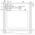
도 1은 본 발명의 일 실시예에 따른 액정 표시 장치의 부분 평면도이다.
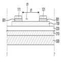
도 2는 도 1의 Ⅰ-Ⅰ’ 라인을 따라 절단한 단면도이다.
도 3은 본 발명의 다른 실시예에 따른 액정 표시 장치의 단면도이다.
도 4는 본 발명의 다른 실시예에 따른 액정 표시 장치의 단면도이다.
도 5는 본 발명의 다른 실시예에 따른 액정 표시 장치의 부분 단면도이다.
도 6은 본 발명의 다른 실시예에 따른 액정 표시 장치의 단면도이다.
도 7은 본 발명의 다른 실시예에 따른 액정 표시 장치의 부분 단면도이다.
도 8은 본 발명의 일 실시예에 따른 액정 표시 장치의 단면도이다.
도 9는 본 발명의 일 실시예에 따른 액정 표시 장치의 제조 방법을 설명하기 위한 단면도이다.
도 10은 본 발명의 일 실시예에 따른 액정 표시 장치의 제조 방법을 설명하기 위한 단면도이다.
도 11은 본 발명의 일 실시예에 따른 액정 표시 장치의 제조 방법을 설명하기 위한 단면도이다.
도 12는 본 발명의 일 실시예에 따른 액정 표시 장치의 제조 방법을 설명하기 위한 단면도이다.
도 13은 본 발명의 일 실시예에 따른 액정 표시 장치의 제조 방법을 설명하기 위한 단면도이다.
도 14는 본 발명의 일 실시예에 따른 액정 표시 장치의 제조 방법을 설명하기 위한 단면도이다.
도 15는 본 발명의 일 실시예에 따른 액정 표시 장치의 제조 방법을 설명하기 위한 단면도이다.
도 16은 본 발명의 일 실시예에 따른 액정 표시 장치의 제조 방법을 설명하기 위한 단면도이다.
도 17은 본 발명의 일 실시예에 따른 액정 표시 장치의 제조 방법을 설명하기 위한 단면도이다.1 is a partial plan view of a liquid crystal display device according to an embodiment of the present invention.
2 is a cross-sectional view taken along the line I-I 'of FIG.
3 is a cross-sectional view of a liquid crystal display device according to another embodiment of the present invention.
4 is a cross-sectional view of a liquid crystal display device according to another embodiment of the present invention.
5 is a partial cross-sectional view of a liquid crystal display device according to another embodiment of the present invention.
6 is a cross-sectional view of a liquid crystal display device according to another embodiment of the present invention.
7 is a partial cross-sectional view of a liquid crystal display device according to another embodiment of the present invention.
8 is a cross-sectional view of a liquid crystal display device according to an embodiment of the present invention.
9 is a cross-sectional view illustrating a method of manufacturing a liquid crystal display device according to an embodiment of the present invention.
10 is a cross-sectional view illustrating a method of manufacturing a liquid crystal display device according to an embodiment of the present invention.
11 is a cross-sectional view illustrating a method of manufacturing a liquid crystal display device according to an embodiment of the present invention.
12 is a cross-sectional view illustrating a method of manufacturing a liquid crystal display device according to an embodiment of the present invention.
13 is a cross-sectional view illustrating a method of manufacturing a liquid crystal display device according to an embodiment of the present invention.
14 is a cross-sectional view illustrating a method of manufacturing a liquid crystal display device according to an embodiment of the present invention.
15 is a cross-sectional view illustrating a method of manufacturing a liquid crystal display device according to an embodiment of the present invention.
16 is a cross-sectional view illustrating a method of manufacturing a liquid crystal display device according to an embodiment of the present invention.
17 is a cross-sectional view illustrating a method of manufacturing a liquid crystal display device according to an embodiment of the present invention.
본 발명의 이점 및 특징, 그리고 그것들을 달성하는 방법은 첨부되는 도면과 함께 상세하게 후술되어 있는 실시예들을 참조하면 명확해질 것이다. 그러나 본 발명은 이하에서 개시되는 실시예들에 한정되는 것이 아니라 서로 다른 다양한 형태로 구현될 수 있으며, 단지 본 실시예들은 본 발명의 개시가 완전하도록 하며, 본 발명이 속하는 기술 분야에서 통상의 지식을 가진 자에게 발명의 범주를 완전하게 알려주기 위해 제공되는 것이며, 본 발명은 청구항의 범주에 의해 정의될 뿐이다.BRIEF DESCRIPTION OF THE DRAWINGS The advantages and features of the present invention, and the manner of achieving them, will be apparent from and elucidated with reference to the embodiments described hereinafter in conjunction with the accompanying drawings. The present invention may, however, be embodied in many different forms and should not be construed as limited to the embodiments set forth herein. Rather, these embodiments are provided so that this disclosure will be thorough and complete, and will fully convey the scope of the invention to those skilled in the art. To fully disclose the scope of the invention to those skilled in the art, and the invention is only defined by the scope of the claims.
제1, 제2 등이 다양한 구성요소들을 서술하기 위해 사용되나, 이들 구성요소들은 이들 용어에 의해 제한되지 않음은 물론이며, 단지 하나의 구성요소를 다른 구성요소와 구별하기 위해 사용하는 것이다. 따라서, 이하에서 언급되는 제1 구성요소는 본 발명의 기술적 사상 내에서 제2 구성요소일 수 있음은 물론이다.The first, second, etc. are used to describe various components, but these components are not limited by these terms, and are used only to distinguish one component from another. Therefore, it goes without saying that the first component mentioned below may be the second component within the technical scope of the present invention.
이하, 첨부된 도면을 참조로 하여 본 발명의 실시예들에 대해 설명한다. 다만, 본 명세서에서는 본 발명에 따른 표시 장치를 액정 표시 장치를 예로 들어 설명하나, 이에 제한되는 것은 아니며 유기 발광 표시 장치의 경우에도 적용될 수 있다.Hereinafter, embodiments of the present invention will be described with reference to the accompanying drawings. However, the display device according to the present invention will be described in the context of a liquid crystal display device, but the present invention is not limited thereto and can be applied to an organic light emitting display device.
도 1은 본 발명의 일 실시예에 따른 액정 표시 장치의 평면도이다. 도 2는 도 1의 'A' 부분을 확대한 부분 단면도이다. 도 3은 도 2의 Ⅰ-Ⅰ' 라인을 따라 절단한 단면도이다. 도 4는 도 2의 Ⅱ-Ⅱ'라인을 따라 절단한 단면도이다. 도 5는 도 2의 Ⅲ-Ⅲ' 라인을 따라 절단한 단면도이다. 도 6은 도 2의 -' 라인을 따라 절단한 단면도이다.1 is a plan view of a liquid crystal display device according to an embodiment of the present invention. 2 is a partial cross-sectional view of an enlarged portion 'A' of FIG. 3 is a cross-sectional view taken along the line I-I 'of Fig. 4 is a cross-sectional view taken along line II-II 'of FIG. 5 is a cross-sectional view taken along line III-III 'of FIG. 6 is a cross-sectional view taken along line '-' of FIG.
도 1 및 도 2를 참조하면, 본 발명의 일 실시예에 따른 액정 표시 장치는 기판(500), 기판(500) 상에 위치하는 게이트 전극(210), 게이트 전극(210) 상에 위치하는 반도체 패턴층(700), 반도체 패턴층(700) 상에 위치하며, 서로 이격된 소스 전극(110) 및 드레인 전극(120)을 포함하되, 소스 전극(110)은 드레인 전극(120)과 대항하는 제1 대향부(110s) 및 제1 대향부(110s)로부터 드레인 전극(120)을 향해 돌출된 제1 돌출부(110_1)을 포함하고, 드레인 전극(120)은 소스 전극(110)과 대향하는 제2 대향부(120s) 및 제2 대향부(120s)로부터 소스 전극(110)을 향해 돌출되어, 제1 돌출부(110_1)과 대향하는 제2 돌출부(120_1)를 포함하며, 반도체 패턴층(700)은 소스 전극(110)과 중첩되는 소스 영역(SA), 드레인 전극(120)과 중첩되는 드레인 영역(DA) 및 소스 영역(SA)과 드레인 영역(DA)를 잇는 브릿지 영역(BA)을 포함한다.1 and 2, a liquid crystal display according to an exemplary embodiment of the present invention includes a
기판(500)은 내열성 및 투광성을 가진 물질로 형성될 수 있다. 기판(500)은 예컨대, 투명 유리 또는 플라스틱으로 형성될 수 있으나, 이에 제한되는 것은 아니다.The
기판(500) 상에는 게이트 배선(200, 210)이 배치될 수 있다. 게이트 배선(200, 210)은 게이트 신호를 전달하는 다수의 게이트 라인(200), 게이트 라인(200)으로부터 돌기 형태로 돌출된 게이트 전극(210) 게이트 라인(200)의 적어도 일단에 배치되는 게이트 끝단(도시하지 않음)을 포함할 수 있다.
게이트 라인(200)은 제1 방향으로 연장될 수 있다. 제1 방향은 도 1에 도시된 바와 같이 가로 방향일 수 있으나, 제1 방향이 이에 제한되는 것은 아니다. 게이트 전극(210)은 후술하는 소스 전극(110) 및 드레인 전극(120)과 함께 박막 트랜지스터의 삼단자를 구성할 수 있다.The
게이트 배선(200, 210)은 알루미늄 합금을 포함하는 알루미늄(Al) 계열의 금속, 은 합금을 포함하는 은(Ag) 계열의 금속, 구리 합금 포함하는 구리(Cu) 계열의 금속, 몰리브덴 합금을 포함하는 몰리브덴(Mo) 계열 금속, 크롬(Cr), 티타늄(Ti), 및 탄탈륨(Ta) 중 어느 하나 이상을 포함할 수 있다. 다만, 이는 예시적인 것으로 게이트 배선(200, 210)의 재질이 이에 제한되는 것은 아니며, 원하는 표시장치를 구현하기 위해 요구되는 성능을 가진 금속 또는 고분자 물질이 게이트 배선(200, 210)의 재료로서 이용될 수 있다.The gate wirings 200 and 210 include an aluminum (Al) based metal including an aluminum alloy, a silver based metal including a silver alloy, a copper based metal including a copper alloy, and a molybdenum alloy And may include at least one of molybdenum (Mo) based metal, chromium (Cr), titanium (Ti), and tantalum (Ta). However, the material of the
게이트 배선(200, 210)은 단일막 구조일 수 있으나, 이에 제한되지 않으며, 이중막, 삼중막 또는 그 이상의 다중막일 수 있다.The gate wirings 200 and 210 may be a single film structure, but are not limited thereto, and may be a double film, a triple film or a multiple film.
게이트 배선(200, 210) 상에는 게이트 절연막(601)이 배치될 수 있다. 게이트 절연막(220)은 게이트 배선(200, 210)을 덮으며, 기판(500)의 전면에 형성될 수 있다.A gate insulating film 601 may be disposed on the
예시적인 실시예에서 게이트 절연막(220)은 실리콘 산화물(SiOx), 실리콘 산화물(SiNx) 등의 무기 절연물질, BCB(BenzoCycloButene), 아크릴계 물질, 및 폴리이미드와 같은 유기 절연 물질로 이루어진 군에서 선택된 어느 하나 또는 하나 이상의 물질을 혼합하여 형성할 수 있다. 다만, 이는 예시적인 것으로 게이트 절연막(220)의 재질이 이에 제한되는 것은 아니다.In the exemplary embodiment, the
게이트 절연막(220) 상에는 반도체 패턴층(700)이 형성될 수 있다.A
반도체 패턴층(700)은 비정질 규소 또는 다결정 규소를 포함할 수 있다. 다만, 이에 제한되는 것은 아니며, 반도체 패턴층(700)은 산화물 반도체를 포함하여 이루어질 수도 있다.The
반도체 패턴층(700)은 섬형, 선형 등과 같은 다양한 형상을 가질 수 있다. 반도체 패턴층(700)이 선형을 갖는 경우, 반도체 패턴층(700)은 데이터 라인(100) 아래에 위치하여 게이트 전극(210) 상부까지 연장될 수 있다.The
예시적인 실시예에서 반도체 패턴층(700)은 채널부(Ch)를 제외한 영역에서 데이터 배선(100, 110, 120, 130)과 실질적으로 동일한 형상으로 패터닝될 수 있다. 다시 말하면, 반도체 패턴층(700)은 채널부(Ch)를 제외한 전 영역에서 데이터 배선(100, 110, 120, 130)과 중첩되도록 배치될 수 있다. 채널부(Ch)는 대향하는 소스 전극(110)과 드레인 전극(120) 사이에 배치될 수 있다. 구체적으로 채널부(Ch)는 후술하는 브릿지 영역(BA)과 전부 또는 일부 중첩될 수 있으나, 이에 제한되는 것은 아니다. 채널부(Ch)는 소스 전극(110)과 드레인 전극(120)이 전기적으로 이어주는 역할을 하며, 그 구체적인 형상은 제한되지 않는다.In the exemplary embodiment, the
예시적인 실시예에서, 반도체 패턴층(700)은 채널부(Ch)를 제외한 데이터 배선(100, 110, 120, 130)과 중첩되되, 데이터 배선(100, 110, 120, 130)에 비해 상대적으로 넓은 폭을 가질 수 있다. 다시 말하면, 반도체 패턴층(700)의 외측벽이 채널부(Ch)를 제외한 데이터 배선(100, 110, 120, 130)의 외측벽에 비해 상대적으로 외측에 배치될 수 있다.In the exemplary embodiment, the
반도체 패턴층(700)은 소스 전극(110)과 중첩되는 소스 영역(SA)과 드레인 전극(120)과 중첩되는 드레인 영역(DA) 및 소스 영역(SA)과 드레인 영역(DA)를 잇는 브릿지 영역(BA)을 포함할 수 있다.The
소스 영역(SA)은 소스 전극(110)의 일부 또는 전부와 중첩될 수 있다. 소스 영역(SA)이 차지하는 넓이는 소스 전극(110)의 넓이와 실질적으로 동일하거나, 그보다 넓을 수 있다. 예를 들어, 소스 영역(SA)의 넓이는 소스 전극(100)의 넓이에 비해 크고, 소스 전극(110)은 소스 영역(SA)의 경계 내측에 배치될 수 있다.The source region SA may overlap with part or all of the
드레인 영역(DA)은 드레인 전극(120)의 일부 또는 전부와 중첩될 수 있다. 드레인 영역(DA)이 차지하는 넓이는 드레인 전극(120)의 넓이와 실질적으로 동일 하거나, 그보다 넓을 수 있다. 예를 들어, 드레인 영역(DA)의 넓이는 드레인 전극(120)의 넓이에 비해 크고, 드레인 전극(120)은 드레인 영역(DA)의 경계 내측에 배치될 수 있다. 구체적으로 설명하기 위해 도 3 및 도 4가 참조된다.The drain region DA may overlap with part or all of the
도 3 및 도 4는 설명의 편의를 위해 드레인 영역(DA) 및 드레인 전극(120)을 예를 들어 설명하지만, 이에 대한 설명은 소스 영역(SA) 및 소스 전극(110)에 대해서도 동일하게 적용될 수 있다.3 and 4 illustrate the drain region DA and the
설명의 편의를 위해 제1 폭(w1), 제2 폭(w2), 제3 폭(w3) 및 제4 폭(w4)의 용어가 정의된다.For convenience of explanation, terms of a first width w1, a second width w2, a third width w3, and a fourth width w4 are defined.
제1 폭(w1)은 드레인 전극(120)의 연장 방향과 수직한 방향의 폭이다. 구체적으로 도 2에서 상하방향의 폭일 수 있다. 다시 말하면, 데이터 라인(100)과 평행한 제2 방향의 폭일 수 있다. 제2 폭(w2)은 드레인 영역(DA)의 연장 방향과 수직한 방향의 폭이다. 구체적으로 도 2에서 상하방향의 폭일 수 있다. 다시 말하면, 데이터 라인(100)과 평행한 제2 방향의 폭일 수 있다. 예시적인 실시예에서 제2 폭(w2)은 제1 폭(w1)에 비해 클 수 있다. 즉, 드레인 전극(120)의 외측이 드레인 영역(DA) 내측에 배치될 수 있다.The first width w1 is a width in a direction perpendicular to the direction in which the
드레인 전극(110)의 외측벽은 도 5에 도시된 바와 같이, 반도체 패턴층(700)의 외측벽에 비해 내측에 배치될 수 있다.The outer side wall of the
제3 폭(w3)과 제4 폭(w4)은 드레인 전극(110)의 외측벽과 반도체 패턴층(700)의 외측벽 사이의 거리이다. 즉, 제3 폭(w3)은 드레인 전극(110) 일측의 외측벽과 반도체 패턴층(700) 일측의 외측벽 사이의 거리이고, 제4 폭(w4)은 드레인 전극(110) 타측의 외측벽과 반도체 패턴층(700) 타측의 외측벽 사이의 거리이다. 예시적인 실시예에서 제3 폭(w3)과 제4 폭(w4)은 실질적으로 동일할 수 있다.The third width w3 and the fourth width w4 are distances between the outer wall of the
도 4를 참조하면, 반도체 패턴층(700) 브릿지 영역(BA)의 제1 방향의 폭인 제5 폭(w5)이 정의될 수 있다. 예시적인 실시예에서 제5 폭(w5)은 제3 폭(w3)과 제4 폭(w4)을 합한 값에 비해 상대적으로 작을 수 있다. 다시 말하면, 도 2에서 브릿지 영역(BA)의 좌우 폭은 도 2에서 드레인 영역(DA)의 상하 폭에서 드레인 전극(120)의 상하 폭을 뺀 값보다 작을 수 있다. 이와 같은 형상 구조는 후술하는 본 발명의 일 실시예에 따른 액정 표시 장치의 제조 방법에 기인할 수 있으나, 이에 제한되는 것은 아니다.Referring to FIG. 4, a fifth width w5 of the
브릿지 영역(BA)은 드레인 전극(DA)과 소스 영역(SA) 사이에 배치될 수 있다. 즉, 브릿지 영역(BA)은 드레인 전극(DA)와 소스 영역(SA)를 잇는 영역일 수 있다. 예시적인 실시예에서 브릿지 영역(BA)의 일부 또는 전부는 앞서 설명한 채널부(Ch)와 중첩될 수 있다. 즉, 채널부(Ch)와 브릿지 영역(BA)은 실질적으로 동일한 폭을 가지며 완전하게 중첩될 수 있지만, 반드시 이에 제한되는 것은 아니며, 브릿지 영역(BA)의 일부에만 채널부(Ch)가 중첩될 수도 있다.The bridge region BA may be disposed between the drain electrode DA and the source region SA. That is, the bridge region BA may be an area connecting the drain electrode DA and the source region SA. In the exemplary embodiment, part or all of the bridge region BA may overlap with the channel portion Ch described above. That is, although the channel portion Ch and the bridge region BA have substantially the same width and can be completely overlapped, the present invention is not necessarily limited thereto, and the channel portion Ch may overlap only a part of the bridge region BA It is possible.
소스 영역(SA)과 드레인 영역(DA)가 이격하여 대항하는 예시적인 실시예에서 브릿지 영역(BA)은 소스 영역(SA)과 드레인 영역(DA)의 이격 공간 중 전부 또는 일부를 차지할 수 있다.In an exemplary embodiment in which the source region SA and the drain region DA are opposed to each other, the bridge region BA may occupy all or part of the spacing space between the source region SA and the drain region DA.
반도체 패턴층(700) 상부에는 n형 불순물이 고농도로 도핑되어 있는 오믹 컨택층(800)이 배치될 수 있다. 오믹 컨택층(800)은 반도체 패턴층(700)의 전부 또는 일부와 중첩될 수 있다. 도 5는 오믹 컨택층(800)이 반도체 패턴층(700)의 일부와 중첩되는 경우를 예시하나, 이는 예시적인 것으로, 이에 제한되는 것은 아니다. 즉, 다른 예시적인 실시예에서 오믹 컨택층(800)은 반도체 패턴층(700)을 전면적으로 덮을 수도 있다. 또한, 다른 예시적인 실시예에서 오믹 컨택층(800)은 생략될 수도 있다.An
오믹 컨택층(800)은 후술하는 소스 전극(110) 및 드레인 전극(120)과 중첩될 수 있다. 오믹 컨택층(800)의 외측벽은 소스 전극(110) 및 드레인 전극(120)의 외측벽과 정렬될 수 있으나, 이에 제한되는 것은 아니며, 오믹 컨택층(800)의 외측벽이 소스 전극(110) 및 드레인 전극(120)의 외측벽에 비해 상대적으로 외측에 배치될 수도 있다.The
반도체 패턴층(700) 상에는 데이터 배선(100, 110, 120, 130)이 배치될 수 있다.
데이터 배선(100, 110, 120, 130)은 제2 방향, 예컨대, 세로 방향으로 연장되어 게이트 라인(200)과 교차하는 데이터 라인(200), 데이터 라인(200)으로부터 가지 형태로 분지되어 반도체 패턴층(700)의 상부까지 연장되어 있는 소스 전극(110), 소스 전극(110)과 이격되어 있으며, 게이트 전극(210) 또는 채널부(Ch)를 중심으로 반도체 패턴층(700) 상부에 소스 전극(110)과 대향하도록 배치되는 드레인 전극(120) 및 드레인 전극(120)으로부터 연장되어 후술하는 화소 전극(300)과 전기적으로 연결되는 드레인 전극 확장부(130)을 포함할 수 있다. 드레인 전극 확장부(130)는 드레인 전극(120)에 비해 상대적으로 넓은 폭을 가져, 화소 전극(300)과의 전기적 접촉을 보다 용이하게 할 수 있다.The data lines 100, 110, 120 and 130 are branched from the
도 2를 참조하여 더욱 구체적으로 설명하면, 소스 전극(110)은 드레인 전극(120)과 대향하는 제1 대향부(110s) 및 제1 대향부로부터 드레인 전극(120)을 향해 돌출되는 제1 돌출부(110_1)를 포함할 수 있다. 제1 돌출부(110_1)의 외주는 도 2에 도시된 바와 같이 드레인 전극(120)을 향해 볼록한 포물선 형상을 가질 수 있으나, 이에 제한되는 것은 아니며, 적어도 부분적으로 곡선을 포함하거나, 다각형 형상을 포함할 수 있다.2, the
드레인 전극(120)은 소스 전극(110)과 대향하는 제2 대향부(120s) 및 제2 대향부(120s)로부터 돌출된 제2 돌출부(120_1)을 포함할 수 있다. 제2 돌출부는(120_1)은 제1 돌출부(110_1)과 대향하도록 배치될 수 있다. 제2 돌출부(120_1)의 외주는 도 2에 도시된 바와 같이 소스 전극(110)을 향해 볼록한 포물선 형상을 가질 수 있으나, 이에 제한되는 것은 아니며, 적어도 부분적으로 곡선을 포함하거나, 다각형 형상을 포함할 수 있다.The
제1 돌출부(110_1)와 제2 돌출부(120_1)은 브릿지 영역(BA)을 사이에 두고 서로 대칭되는 형상을 가질 수 있으나, 이에 제한되는 것은 아니며, 서로 상이한 형상을 가질 수도 있다.The first protrusions 110_1 and the second protrusions 120_1 may be symmetrical with respect to each other with the bridge region BA therebetween. However, the first protrusions 110_1 and the second protrusions 120_1 may have different shapes from each other.
제1 돌출부(110_1)와 제2 돌출부(120_1)는 서로 이격되어 배치된다. 구체적으로 제1 돌출부(110_1)와 제2 돌출부(120_1) 사이에는 일정한 이격 공간이 정의될 수 있다. 예시적인 실시예에서 이격 공간은 브릿지 영역(BA) 상에 배치될 수 있다. 이에 대해 다시 설명하면, 제1 돌출부(110_1)과 제2 돌출부(120_1)을 잇는 가상의 정렬선(AL)이 정의될 수 있다. 정렬선(AL)은 제1 돌출부(110_1)의 외주 상의 한점과 제2 돌출부(120_1)의 외주 상의 한점을 잇는 선으로서, 제1 돌출부(110_1)와 제2 돌출부(120_1)의 최단거리를 정의하는 선과 동일할 수 있다. 예시적인 실시예에서 정렬선(AL)은 브릿지 영역(BA) 상에 배치될 수 있다. 즉, 정렬선(AL)은 브릿지 영역(BA)을 가로지르도록 배치될 수 있다.The first protrusion 110_1 and the second protrusion 120_1 are spaced apart from each other. Specifically, a certain spacing space may be defined between the first protrusion 110_1 and the second protrusion 120_1. In an exemplary embodiment, the spacing space may be disposed on the bridge area BA. In other words, a virtual alignment line AL connecting the first protrusion 110_1 and the second protrusion 120_1 can be defined. The alignment line AL is a line connecting one point on the outer periphery of the first projection 110_1 and one point on the outer periphery of the second projection 120_1 and defines a shortest distance between the first projection 110_1 and the second projection 120_1 ≪ / RTI > In an exemplary embodiment, the alignment line AL may be disposed on the bridge region BA. That is, the alignment line AL may be arranged to cross the bridge area BA.
도 2에는 제1 돌출부(110_1)와 제2 돌출부(120_1)의 최단 거리인 제1 거리(d1)가 도시되어 있다. 제1 거리(d1)는 제1 돌출부(110_1)의 외주 상의 한점과 제2 돌출부(120_1)의 외주 상의 한점을 잇는 선 중 그 거리가 가장 짧은 선일 수 있다. 또한, 소스 영역(SA)과 드레인 영역(DA) 사이에 배치되되, 브릿지 영역(BA)이 아닌 영역에서의 서로 대향하는 소스 전극(110)의 제1 대향부(110s)와 드레인 전극(120)의 제2 대향부(120s) 사이의 거리인 제2 거리(d2)가 정의될 수 있다. 제1 거리(d1)는 제2 거리(d2)에 비해 짧을 수 있다. 다시 말하면, 채널부(Ch)가 형성된 부분에서의 소스 전극(110)과 드레인 전극(120) 사이의 거리가 채널부(Ch)가 형성된 부분을 제외한 나머지 부분에서의 소스 전극(110)과 드레인 전극(120) 사이의 거리에 비해 작을 수 있다.In FIG. 2, the first distance d1 is the shortest distance between the first protrusion 110_1 and the second protrusion 120_1. The first distance d1 may be a line having the shortest distance among the lines connecting one point on the outer periphery of the first projection 110_1 and one point on the outer periphery of the second projection 120_1. The first opposing portion 110s and the
데이터 배선(100, 110, 120, 130)은 니켈(Ni), 코발트(Co), 티탄(Ti), 은(Ag), 구리(Cu), 몰리브덴(Mo), 알루미늄(Al), 베릴륨(Be), 니오브(Nb), 금(Au), 철(Fe), 셀렌(Se) 또는 탄탈(Ta) 등으로 이루어진 단일막 또는 다중막 구조를 가질 수 있다. 또한, 상기 금속에 티탄(Ti), 지르코늄(Zr), 텅스텐(W), 탄탈(Ta), 니오브(Nb), 백금(Pt), 하프늄(Hf), 산소(O) 및 질소(N)로 이루어진 군에서 선택된 하나 이상의 원소를 포함시켜 형성한 합금도 적용할 수 있다. 다만, 상기한 재료는 예시적인 것으로, 데이터 배선(100, 110, 120, 130)의 재질이 이에 제한되는 것은 아니다.The data lines 100, 110, 120, and 130 may be formed of a material selected from the group consisting of Ni, Co, Ti, Ag, Cu, Mo, ), Niobium (Nb), gold (Au), iron (Fe), selenium (Se) or tantalum (Ta). Further, it is also possible to use a metal such as titanium (Ti), zirconium (Zr), tungsten (W), tantalum (Ta), niobium (Nb), platinum (Pt), hafnium (Hf), oxygen An alloy formed by incorporating at least one element selected from the group consisting of the foregoing can also be applied. However, the material is not limited to the material of the
제1 돌출부(110_1)와 제2 돌출부(120_1)가 대향하는 경우, 적절한 채널 길이를 확보하여 도전 특성이 우수한 박막 트랜지스터를 구현할 수 있다.When the first protrusion 110_1 and the second protrusion 120_1 are opposed to each other, a thin film transistor having an appropriate channel length and excellent conductivity can be realized.
이하, 본 발명의 다른 실시예들에 대해 설명한다. 이하의 실시예에서 이미 설명한 구성과 동일한 구성에 대해서는 동일한 참조 번호로서 지칭하며, 중복 설명은 생략하거나 간략화하기로 한다.Hereinafter, other embodiments of the present invention will be described. In the following embodiments, the same components as those already described are referred to as the same reference numerals, and redundant description will be omitted or simplified.
도 7은 본 발명의 다른 실시예에 따른 액정 표시 장치의 단면도이다. 도 7의 실시예는 소스 전극(111), 드레인 전극(121) 및 오믹 콘택층(801)이 테이퍼진 형상을 가질 수 있음을 예시한다.7 is a cross-sectional view of a liquid crystal display device according to another embodiment of the present invention. The embodiment of FIG. 7 illustrates that the source electrode 111, the
도 7을 참조하여 구체적으로 설명하면, 오믹 콘택층(801)은 소스 전극(111) 및/또는 드레인 전극(121)과 중첩될 수 있다. 소스 전극(111) 및 드레인 전극(121)의 측벽이 테이퍼진 형상을 갖는 경우 오믹 콘택층(801)의 측벽은 테이퍼진 형상을 가질 수 있다. 예시적인 실시예에서, 소스 전극(111) 및 드레인 전극(121)의 측벽은 오믹 콘택층(801)의 측벽과 정렬될 수 있다. 다시 말하면, 소스 전극(111) 및 드레인 전극(121)의 외측벽과 오믹 콘택층(801)의 외측벽은 동일한 경사각을 가지며 연속된 경사를 이룰 수 있다.7, the
다만, 이 경우에도, 오믹 콘택층(801)의 하부 끝단은 반도체 패턴층(700)의 외측벽에 비해 상대적으로 내측에 위치할 수 있다. 예를 들어, 등방성 식각으로 소스/드레인 전극(111, 121) 및 오믹 콘택층(801)을 동시 또는 순차적으로 식각하고, 반도체 패턴층(700)을 이방성 식각하는 경우 상기와 같은 구조가 형성될 수 있다. 다만, 이는 예시적인 것으로, 상기의 구조를 형성하는 방법이 이에 제한되는 것은 아니다.In this case, the lower end of the
도 8은 본 발명의 다른 실시예에 따른 액정 표시 장치의 평면도이다.8 is a plan view of a liquid crystal display device according to another embodiment of the present invention.
도 8은 브릿지 영역(BA1)은 복수개인 경우를 예시한다.FIG. 8 illustrates a case where there are a plurality of bridge areas BA1.
도 8을 참조하면, 브릿지 영역(BA1)은 일정 간격 이격되어 두 개 이상 배치될 수 있다. 도 8에서는 브릿지 영역(BA1)이 세 개 형성된 경우를 예시하지만, 이는 예시적인 것으로 브릿지 영역(BA1)의 개수가 이에 제한되는 것은 아니다. 즉, 다른 예시적인 실시예에서 브릿지 영역의 개수는 3개 이상이거나, 3개 미만일 수도 있다.Referring to FIG. 8, more than two bridge areas BA1 may be spaced apart by a predetermined distance. Although FIG. 8 exemplifies the case where three bridge areas BA1 are formed, this is an exemplary one, and the number of the bridge areas BA1 is not limited thereto. That is, in other exemplary embodiments, the number of bridge regions may be three or more, or less than three.
브릿지 영역(BA1)은 제1 방향으로 정렬되어 배치될 수 있다. 다만, 이는 예시적인 것으로, 소스 전극 및 드레인 전극의 형상에 따라 브릿지 영역의 배열구조는 상이할 수 있다.The bridge areas BA1 may be arranged in the first direction. However, this is an example, and the arrangement of the bridge regions may be different depending on the shapes of the source electrode and the drain electrode.
브릿지 영역(BA1)이 복수개 형성되는 경우, 이와 대응되도록 제1 돌출부(112_1)도 복수개 형성될 수 있다. 즉, 복수개의 브릿지 영역(BA1)이 일정 간격 이격되며, 제1 방향을 따라 정렬되는 예시적인 실시예에서 복수개의 제1 돌출부(112_1)는 브릿지 영역(BA1)에 대응되도록 일정 간격 이격되며, 제1 방향을 따라 정렬되어 배치될 수 있다.When a plurality of bridge regions BA1 are formed, a plurality of first protrusions 112_1 may be formed to correspond to the bridge regions BA1. That is, in the exemplary embodiment where the plurality of bridge areas BA1 are spaced apart from each other by a predetermined distance and are aligned along the first direction, the plurality of first projections 112_1 are spaced apart from each other by a predetermined distance corresponding to the bridge area BA1, They can be arranged along one direction.
브릿지 영역(BA1)이 복수개 형성되는 경우, 이와 대응되도록 제2 돌출부(122_1)도 복수개 형성될 수 있다. 즉, 복수개의 브릿지 영역(BA1)이 일정 간격 이격되며, 제1 방향을 따라 정렬되는 예시적인 실시예에서 복수개의 제1 돌출부(122_1)는 브릿지 영역(BA1)에 대응되도록 일정 간격 이격되며, 제1 방향을 따라 정렬되어 배치될 수 있다.When a plurality of bridge regions BA1 are formed, a plurality of second projections 122_1 may be formed to correspond to the bridge regions BA1. That is, in the exemplary embodiment in which the plurality of bridge areas BA1 are spaced apart from each other by a predetermined distance and are aligned along the first direction, the plurality of first projections 122_1 are spaced apart from each other by a predetermined distance corresponding to the bridge area BA1, They can be arranged along one direction.
복수개의 제1 돌출부(112_1)와 복수개의 제2 돌출부(122_1)는 서로 대향할 수 있다. 즉, 대응되는 각각의 제1 돌출부(112_1)와 제2 돌출부(122_1)는 서로 대향할 수 있으며, 제1 돌출부(112_1)와 제2 돌출부(121_1) 사이의 이격 공간은 각각 대응되는 브릿지 영역(BA1)상에 배치될 수 있다.The plurality of first protrusions 112_1 and the plurality of second protrusions 122_1 may be opposed to each other. That is, the first protrusions 112_1 and the second protrusions 122_1 corresponding to each other can be opposed to each other, and the spacing spaces between the first protrusions 112_1 and the second protrusions 121_1 correspond to the corresponding bridge regions BA1). ≪ / RTI >
도 9는 본 발명의 다른 실시예에 따른 액정 표시 장치의 평면도이다.9 is a plan view of a liquid crystal display device according to another embodiment of the present invention.
도 9를 참조하면, 본 발명의 다른 실시예에 따른 액정 표시 장치는 U자 형상을 포함하는 소스 전극(113)과 U자 형상의 소스 전극(113)과 대향하는 I자 형상의 드레인 전극(123)을 포함할 수 있다.9, a liquid crystal display according to another embodiment of the present invention includes a
구체적으로 설명하면, 소스 전극(113)은 U자 형상을 포함할 수 있다. 즉, 소스 전극(113)은 일면이 개구되고, 나머지 3면이 폐쇄되는 형상을 가질 수 있다. 드레인 전극(123)은 I자 형상으로 이루어지며, 소스 전극(113)의 개구된 일면에 일부 삽입될 수 있다. 즉, U자 형상의 소스 전극(113)이 I자 형상의 드레인 전극(123)의 외측을 둘러 싸는 형상을 가질 수 있다. 다만, 이 경우에도, 소스 전극(113)과 드레인 전극(123)은 분리 이격되며 직접적으로 접하지 않는다.More specifically, the
소스 전극(113)이 U자 형상을 갖고, 드레인 전극(123)이 I자 형상을 갖는 예시적인 실시예에서 소스 영역(SA1)과 드레인 영역(DA1)은 소스 전극(113)과 드레인 전극(123)의 형상에 대응되는 형상을 가질 수 있다. 구체적으로 소스 영역(SA1)은 U자 형상을 갖고, 드레인 영역(DA1)은 I자 형상을 가질 수 있다. 즉, 소스 전극(113)은 소스 영역(SA1)에 중첩되고, 드레인 전극(123)은 드레인 영역(DA1)에 중첩될 수 있다.In the exemplary embodiment in which the
소스 영역(SA1)이 U자 형상을 포함하고, 드레인 영역(DA1)이 I자 형상을 포함하는 예시적인 실시예에서, 브릿지 영역(BA2)는 U자 형상에 의해 구획된 공간 내에 배치될 수 있다. 구체적으로 드레인 영역(DA1)의 일부가 소스 영역(SA1)의 U자 형상에 의해 구획된 공간에 배치될 수 있고, 복수개의 브릿지 영역(BA2)은 그 공간 내에 배치되어 소스 영역(SA1)과 드레인 영역(DA1)을 이을 수 있다. 예시적인 실시예에서 브릿지 영역(BA2)은 하나 이상 형성될 수 있다.In an exemplary embodiment in which the source region SA1 includes a U-shape and the drain region DA1 includes an I-shape, the bridge region BA2 may be disposed in a space defined by the U-shape . Particularly, a part of the drain region DA1 may be arranged in a space defined by the U-shape of the source region SA1, and a plurality of bridge regions BA2 may be arranged in the space to form the source region SA1 and the drain It can be the region DA1. At least one bridge region BA2 may be formed in the exemplary embodiment.
브릿지 영역(BA2)은 제1 방향 또는 제2 방향으로 연장되거나, 제1 방향 및/또는 제2 방향으로부터 일정 각도 기울어진 제3 방향으로 연장될 수도 있다. 예를 들어, 복수개의 브릿지 영역(BA2)이 형성되는 경우, 브릿지 영역(BA2)은 제1 방향으로 연장된 브릿지 영역, 제2 방향으로 연장된 브릿지 영역 및 제3 방향으로 연장된 브릿지 영역 중 어느 하나 이상을 포함할 수 있다. 도 9는 제1 방향으로 연장된 브릿지 영역 2개, 제2 방향으로 연장된 브릿지 영역 1개 및 제3 방향(도 9에서 사선 방향)으로 연장된 브릿지 영역을 포함하지만, 이는 예시적인 것으로, 브릿지 영역(BA2)의 배열이 이에 제한되는 것은 아니며, 제1 방향, 제2 방향 및 제3 방향의 다양한 조합이 가능하다.The bridge region BA2 may extend in a first direction or a second direction, or may extend in a third direction that is inclined at a certain angle from the first direction and / or the second direction. For example, when a plurality of bridge areas BA2 are formed, the bridge area BA2 may be either a bridge area extending in the first direction, a bridge area extending in the second direction, or a bridge area extending in the third direction, And may include one or more. Figure 9 includes two bridge regions extending in a first direction, one bridge region extending in a second direction and a bridge region extending in a third direction (diagonal in Figure 9), but this is illustrative only, The arrangement of the area BA2 is not limited thereto, and various combinations of the first direction, the second direction and the third direction are possible.
브릿지 영역(BA2)이 복수개 형성되는 경우, 이와 대응되도록 제1 돌출부(113_1)도 복수개 형성될 수 있다. 즉, 복수개의 브릿지 영역(BA2)이 U자 형상의 소스 영역(SA1)에 의해 구획된 공간 내측에 형성되는 예시적인 실시예에서, 제1 돌출부(113_1)는 U자 형상의 제1 대향부(113s)로부터 드레인 전극(123)을 향해 돌출될 수 있다. 제1 돌출부(113_1)는 복수개일 수 있으나, 이에 제한되는 것은 아니며, 적어도 하나의 제1 돌출부(113_1)이 형성될 수 있다. 제1 돌출부(113_1)는 브릿지 영역(BA2)과 대응되도록 형성되며, 브릿지 영역(BA2)의 개수와 제1 돌출부(113_1)의 개수는 동일할 수 있다. 다만, 이에 제한되는 것은 아니며, 다른 예시적인 실시예에서는 제1 돌출부(113_1)의 개수가 브릿지 영역(BA2)의 개수보다 많거나 적을 수 있다.When a plurality of bridge regions BA2 are formed, a plurality of first protrusions 113_1 may be formed to correspond to the bridge regions BA2. That is, in the exemplary embodiment in which a plurality of bridge regions BA2 are formed inside the space partitioned by the U-shaped source region SA1, the first projection 113_1 has a U-shaped first opposing portion 113s toward the
제2 돌출부(123_1)는 제1 돌출부(113_1)에 대응되도록 배치될 수 있다. 제2 돌출부(123_1)는 제2 대향부(123s)로부터 돌출 형성될 수 있음은 앞서 설명한 바와 같다. 구체적으로, 제1 돌출부(113_1)가 복수개 형성되는 경우, 제2 돌출부(123_1)는 제1 돌출부(113_1)와 대응되도록 복수개 형성될 수 있고, 나아가, 제1 돌출부(113_1)와 제2 돌출부(123_1)의 개수가 동일할 수 있다. 다만, 이에 제한되는 것은 아니며 제2 돌출부(123_1)의 개수는 제1 돌출부(113_1)의 개수보다 많거나 적을 수도 있다.The second protrusion 123_1 may be disposed to correspond to the first protrusion 113_1. The second protrusion 123_1 may be protruded from the second opposing portion 123s as described above. Specifically, when a plurality of the first protrusions 113_1 are formed, the second protrusions 123_1 can be formed to correspond to the first protrusions 113_1, and further, the first protrusions 113_1 and the second protrusions 113_1 123_1 may be the same. However, the present invention is not limited thereto, and the number of the second projections 123_1 may be larger or smaller than the number of the first projections 113_1.
제1 돌출부(113_1)는 제1 방향, 제2 방향 및 제3 방향 중 어느 한 방향으로 돌출될 수 있으며, 이에 대향하는 제2 돌출부(123_1) 또한 제1 방향, 제2 방향 및 제3 방향 중 어느 한 방향으로 돌출 될 수 있다. 예컨대, 제1 방향으로 돌출 형성된 제1 돌출부는 제1 방향으로 돌출 형성된 제2 돌출부와 대향할 수 있다.The first protrusion 113_1 may protrude in any one of the first direction, the second direction, and the third direction, and the second protrusion 123_1 facing the first protrusion 113_1 may also protrude in the first direction, the second direction, It may protrude in either direction. For example, the first projection projected in the first direction may be opposed to the second projection projected in the first direction.
이하에서는, 본 발명의 일 실시예에 따른 액정 표시 장치의 제조 방법에 대해 설명하기로 한다. 이하에서 설명하는 구성의 일부는 앞서 본 발명의 몇몇 실시예에 따른 액정 표시 장치의 구성과 동일할 수 있으며, 중복 설명을 피하기 위해 일부 구성에 대한 설명은 생략될 수 있다.Hereinafter, a method of manufacturing a liquid crystal display device according to an embodiment of the present invention will be described. Some of the components described below may be the same as those of the liquid crystal display according to some embodiments of the present invention, and descriptions of some components may be omitted in order to avoid redundant description.
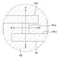
도 10은 본 발명의 일 실시예에 따른 액정 표시 장치의 제조 방법을 설명하기 위한 평면도이다. 도 11 내지 도 14는 본 발명의 일 실시예에 따른 액정 표시 장치의 제조 방법을 설명하기 위한 단면도이다. 도 11 내지 도 14는 도 10의 -'라인을 따라 절단한 단면도와 -' 라인을 따라 절단한 단면도를 포함한다.10 is a plan view for explaining a method of manufacturing a liquid crystal display device according to an embodiment of the present invention. 11 to 14 are cross-sectional views illustrating a method of manufacturing a liquid crystal display device according to an embodiment of the present invention. Figs. 11 to 14 include cross-sectional views taken along the line-and-line in Fig. 10, respectively.
본 발명의 일 실시예에 따른 액정 표시 장치의 제조 방법은 제1 도전막(250), 게이트 절연막(220), 반도체층(750), 오믹 콘택층(800) 및 제2 도전막(150)이 순차적으로 적층된 기판을 준비하는 단계, 기판에 제1 영역(PR_1), 제1 영역(PR_1)과 대향하는 제2 영역(PR_2) 및 제1 영역(PR_1)과 제2 영역(PR_2)를 잇는 제3 영역(PR_3)을 포함하는 감광막 패턴(PR)을 형성하는 단계, 감광막 패턴(PR)을 식각 마스크로 하여 제2 도전막(150)과 오믹 콘택층(800)을 식각하여, 제1 영역(PR_1) 하부에 소스 전극(110), 제2 영역(PR_2)하부에 드레인 전극(120) 및 제3 영역(PR_3) 하부에 채널부(Ch)를 형성하는 단계, 감광막 패턴(PR)을 식각 마스크로 반도체층(750)을 식각하여, 제1 영역(PR_1) 하부에 배치되며, 소스 전극(110)과 중첩되는 소스 영역(SA), 제2 영역(PR_2) 하부에 배치되며, 드레인 전극(120)과 중첩되는 드레인 영역(DA), 제3 영역(PR_3) 하부에 배치되며, 소스 영역(SA)과 드레인 영역(DA)을 잇는 브릿지 영역(BA)을 포함하는 반도체 패턴층(700)을 형성하는 단계를 포함한다.A method of manufacturing a liquid crystal display according to an exemplary embodiment of the present invention includes forming a first
먼저, 도 10 및 도 11을 참조하면, 기판(500) 상에 제1 도전막(250)을 형성한다. 제1 도전막(250)은 게이트 배선용 도전체로 형성할 수 있다. 제1 도전막(250)은 화학 기상 증착, 플라즈마 화학 기상 증착, 물리 기상 증착, 스퍼터링 등의 방법으로 형성될 수 있다.First, referring to FIGS. 10 and 11, a first
이어, 제1 도전막(250) 상에 게이트 절연막(220)을 형성한다. 게이트 절연막(220)은 화학 기상 증착 등의 방법으로 형성될 수 있다.Next, a
이어, 게이트 절연막(220) 상에 반도체층(750)과 오믹 콘택층(800)을 형성한다. 반도체층(750)과 오믹 콘택층(800)은 각각 화학 기상 증착 등의 방법으로 순차적으로 형성될 수 있다. 반도체층(750)과 오믹 콘택층(800)은 소스 가스를 공유할 수 있다. 따라서, 반도체층(750)과 오믹 콘택층(800)은 인-시츄(in-situ)하게 형성될 수 있다.Next, a
제1 도전막(250)은 식각되어 본 발명의 몇몇 실시예에 따른 액정 표시 장치에 적용되는 게이트 전극(210)을 형성할 수 있다. 즉, 제1 도전막(250)은 상술한 게이트 전극(210)과 실질적으로 동일한 물질로 이루어질 수 있다.The first
이어서, 제1 도전막(250) 상에 게이트 절연막(220)이 형성될 수 있다. 게이트 절연막(220)은 게이트 전극(210)과 기판(500)을 덮도록 배치될 수 있다.Then, a
게이트 절연막(220) 상에는 반도체층(750)이 배치될 수 있다. 반도체층(750)은 식각되어 본 발명의 몇몇 실시예에 따른 액정 표시 장치의 반도체 패턴층(700)을 형성할 수 있다. 즉, 반도체층(750)은 본 발명의 몇몇 실시예에 따른 반도체 패턴층(700)과 실질적으로 동일한 물질로 형성될 수 있으며, 이에 대한 자세한 설명은 중복 설명이 되므로 생략하기로 한다.A
반도체층(750) 상에는 오믹 콘택층(800)이 형성되고, 오믹 콘택층(800) 상에는 제2 도전막(150)이 형성될 수 있다. 제2 도전막(150)은 식각되어 본 발명의 몇몇 실시예에 따른 데이터 배선(100, 110, 120, 130)을 형성할 수 있다. 즉, 제2 도전막(150)은 데이터 배선(100, 110, 120, 130)과 실질적으로 동일한 물질로 형성될 수 있다.The
제2 도전막(150) 상에는 제1 영역(PR_1), 제2 영역(PR2), 제3 영역(PR_3)을 포함하는 감광막 패턴(PR)이 형성될 수 있다. 구체적으로 제1 영역(PR_1)은 제1 방향으로 연장될 수 있다. 제2 영역(PR_2)은 제1 영역(PR_1)과 분리 이격되며, 제1 영역(PR_1)과 나란하도록 배치될 수 있다. 즉, 제1 영역(PR_1)과 제2 영역(PR_2)은 서로 대향할 수 있다. 제3 영역(PR_3)은 제1 영역(PR_1)과 제2 영역(PR_2) 사이에 배치되며, 제1 영역(PR_1)과 제2 영역(PR_2) 사이에 배치되며, 제1 영역(PR_1)과 제2 영역(PR_2)을 이을 수 있다.A photoresist pattern PR including a first area PR_1, a second area PR2 and a third area PR_3 may be formed on the second
예시적인 실시예에서 제1 영역(PR_1)은 제2 영역(PR_2)와 평행하게 배치되고, 제3 영역(PR_3)은 제2 방향으로 연장되어 제1 영역(PR_1)과 제2 영역(PR_2)을 이을 수 있다. 다만, 이는 예시적인 것으로, 제3 영역(PR_3)의 구조가 이에 제한되는 것은 아니다.In the exemplary embodiment, the first area PR_1 is arranged parallel to the second area PR_2, the third area PR_3 extends in the second direction to form the first area PR_1 and the second area PR_2, . However, this is an example, and the structure of the third area PR_3 is not limited thereto.
제1 영역(PR_1), 제2 영역(PR_3) 및 제3 영역(PR_3)의 두께는 실질적으로 동일할 수 있다. 여기서 두께라 함은, 도 11 내지 도 14의 단면에서 보았을 때, 상면과 하면간의 거리 차를 의미할 수 있다.The thicknesses of the first region PR_1, the second region PR_3, and the third region PR_3 may be substantially the same. Here, the thickness may mean a distance difference between the upper surface and the lower surface when viewed from the cross-section of Figs. 11 to 14. Fig.
이어서, 도 12를 참조하면, 감광막 패턴(PR)을 식각 마스크로 제2 도전막(150)과 오믹 콘택층(800)을 식각할 수 있다. 제2 도전막(150)과 오믹 콘택층(800)은 동일한 에천트에 의해 동시에 또는 순차적으로 식각될 수 있다. 다만, 이는 예시적인 것으로 제2 도전막(150)과 오믹 콘택층(800)이 서로 상이한 에천트에 의해 식각될 수도 있다.Referring to FIG. 12, the second
제2 도전막(150)과 오믹 콘택층(800)은 등방성 식각될 수 있다. 제2 도전막(150)과 오믹 콘택층(800)이 식각되면, 소스 전극(110), 드레인 전극(120) 및 채널부(Ch)가 형성될 수 있다. 오믹 콘택층(800)은 소스 전극(110) 및 드레인 전극(120)과 중첩되도록 형성될 수 있다. 오믹 콘택층(800)의 측벽과 소스 전극(110) 및 드레인 전극(120)의 측벽이 정렬될 수 있음은 앞서 도 5 및 도 7에서 설명한 바와 같다.The second
소스 전극(110), 드레인 전극(120) 및 채널부(Ch)가 형성되는 과정에 대해 더 자세히 설명하면, 제2 도전막(150)이 등방성 식각되는 경우, 소스 전극(110) 및 드레인 전극(120)의 외측벽은 감광막 패턴(PR)의 외측벽의 연장선보다 내측에 형성될 수 있다. 이는 등방성 식각으로 인한 스쿠(Skew) 현상에 기인할 수 있다. 즉, 등방성 식각에 의해 감광막 패턴(PR)의 외측벽의 연장선에서 내측을 향해 측면 식각이 진행될 수 있다. 이 경우, 제3 영역(PR_3)의 폭이 충분이 작을 경우, 다시 말하면, 제3 영역(PR_3)폭이 제1 영역(PR_1) 및 제2 영역(PR_2)에 비해 현저하게 작을 경우, 제3 영역(PR_3)의 일측에서 진행되는 측면 식각과 타측에서 진행되는 측면 식각에 의해 제3 영역(PR_3) 하부에 배치되는 제2 도전막(150)이 관통되어 터널이 형성될 수 있다. 이와 같은 터널이 소스 전극(110)과 드레인 전극(120) 사이에 배치되어 채널부(Ch)를 형성할 수 있다. 도 3 및 도 4를 참조하여 다시 설명하면, 드레인 전극(120)의 외측에서 등방성 식각이 진행되어 제3 폭(w3) 및 제4 폭(w4)만큼의 측면 식각이 진행될 수 있다. 이 경우, 제3 영역(PR_3)의 하부에서도 위와 같은 정도의 측면 식각이 일어날 수 있으며, 제 3영역(PR_3)의 폭이 제3 폭(w4) 및 제4 폭(w4)의 합보다 작다면, 제3 영역(PR_3) 하부의 제2 도전막(150)이 관통되어 채널부(Ch)가 형성될 수 있다.The process of forming the
또한, 감광막 패턴(PR)을 식각 마스크로 제2 도전막(150)과 오믹 콘택층(800)을 식각하여 제1 영역(PR_1) 하부에 소스 전극(110), 제2 영역(PR_2) 하부에 드레인 전극(120) 및 제3 영역(PR_3) 하부에 채널부(Ch)를 형성하는 단계는 제1 대향부(110s)로부터 드레인 전극(120)을 향해 돌출되는 제1 돌출부(110_1)를 형성하는 단계 및 제2 대향부(120s)로부터 제1 돌출부(110_1)를 향해 돌출되며, 제1 돌출부(110_1)과 대향하는 제2 돌출부(120_1)를 형성하는 단계를 포함할 수 있다.The second
구체적으로, 제1 돌출부(110_1)는 제1 영역(PR_1) 과 제3 영역(PR_3)이 이어지는 부분 (도 10에서 'T'자를 이루는 부분) 하부에 형성될 수 있다. 앞서 설명한 바와 같이 제2 도전막(150)을 등방성 식각하는 경우, 측면 식각이 진행될 수 있다. 제1 영역(PR_1) 과 제3 영역(PR_3)이 연결되는 부분에서의 측면 식각은 제1 영역(PR_1) 과 제3 영역(PR_3)이 연결되는 부분을 제외한 나머지 부분에서의 측면 식각에 비해 열세일 수 있다. 즉, 제1 영역(PR_1)의 일측과 타측에서 측면 식각이 동시에 진행될 수 있는데, 제3 영역(PR_3)과 접하는 지점에서의 측면 식각은 제3 영역(PR_3)의 존재로 인해 다른 부분에 비해 약할 수 있으며, 이로 인해 제3 영역(PR_3)하부에는 제3 영역(PR_3)의 연장 방향으로 돌출되는 제1 돌출부(110_1)이 형성될 수 있다.Specifically, the first protrusion 110_1 may be formed below the portion (the portion forming the 'T' character in FIG. 10) where the first region PR_1 and the third region PR_3 are continuous. As described above, when the second
제2 돌출부(120_1)도 이와 실질적으로 동일한 방식으로 형성될 수 있다. 제2 돌출부(120_1)는 제2 영역(PR_2) 과 제3 영역(PR_3)이 이어지는 부분 (도 10에서 'T'자를 이루는 부분) 하부에 형성될 수 있다. 앞서 설명한 바와 같이 제2 도전막(150)을 등방성 식각하는 경우, 측면 식각이 진행될 수 있다. 제2 영역(PR_2) 과 제3 영역(PR_3)이 연결되는 부분에서의 측면 식각은 제2 영역(PR_2) 과 제2 영역(PR_3)이 연결되는 부분을 제외한 나머지 부분에서의 측면 식각에 비해 열세일 수 있다. 즉, 제2 영역(PR_2)의 일측과 타측에서 측면 식각이 동시에 진행될 수 있는데, 제3 영역(PR_3)과 접하는 지점에서의 측면 식각은 제3 영역(PR_3)의 존재로 인해 다른 부분에 비해 약할 수 있으며, 이로 인해 제3 영역(PR_3)하부에는 제3 영역(PR_3)의 연장 방향으로 돌출되는 제2 돌출부(120_1)가 형성될 수 있다. 즉, 제3 영역(PR_3)의 하부에서 제1 돌출부(110_1)와 제2 돌출부(120_1)는 서로 이격되며, 대향하도록 형성될 수 있다.The second projection 120_1 may also be formed in substantially the same manner. The second protrusion 120_1 may be formed below the portion where the second region PR_2 and the third region PR_3 are continuous (the portion forming the 'T' character in FIG. 10). As described above, when the second
이어서, 감광막 패턴(PR)을 그대로 유지한 채, 이를 식각 마스크로 하여 반도체층(750)을 식각하는 단계가 진행될 수 있다. 반도체층(750)은 이방성 식각될 수 있다. 반도체층(750)의 식각은 건식 식각 방식에 의할 수 있으나, 이에 제한되는 것은 아니다. 반도체층(750)이 식각되면, 제1 영역(PR_1) 하부에 배치되며 소스 전극(110)과 중첩되는 소스 영역(SA), 제2 영역(PR_2) 하부에 배치되며, 드레인 전극(120)과 중첩되는 드레인 영역(DA) 및 제3 영역(PR_3) 하부에 배치되며, 소스 영역(SA)과 드레인 영역(DA)을 잇는 브릿지 영역(BA)을 포함하는 반도체 패턴층(700)이 형성될 수 있다. 소스 영역(SA), 드레인 영역(DA) 및 브릿지 영역(BA)은 본 발명의 몇몇 실시예에 따른 액정 표시 장치에서 설명한 것과 실절적으로 동일할 수 있다. 따라서, 이에 대한 자세한 설명은 생략하기로 한다.Then, the
이방성 식각을 진행하는 경우, 측면 식각은 등방석 식각에 비해 열세일 수 있다. 즉, 이방성 식각을 진행하는 경우, 반도체 패턴층(700)의 외측은 감광막 패턴(PR)의 외측벽의 연장선과 정렬될 수 있다. 또한, 측면 식각이 진행되는 경우에도, 반도체 패턴층(700)의 외측벽은 소스 전극(110), 드레인 전극(120) 및 오믹 콘택층(800)의 외측벽에 비해 상대적으로 외측에 배치될 수 있다.When anisotropic etching is performed, the lateral etching may be inferior to the back cushion etching. That is, when the anisotropic etching is performed, the outside of the
도면에 도시하지는 않았지만, 데이터 배선(100, 110, 120, 130) 상에는 드레인 전극(120)의 일부를 노출시키는 패시베이션막이 배치될 수 있다. 패시베이션 막이 노출시키는 드레인 전극(120)은 패시베이션막 상에 배치되는 화소 전극(도시하지 않음)과 전기적으로 연결될 수 있다. 이에 더하여, 본 발명의 일 실시예에 따른 액정 표시 장치는 기판과 대향되는 상부 절연 기판(도시하지 않음) 등을 더 포함할 수 있다. 상부 절연 기판 상에는 공통 전극(도시하지 않음), 블랙 매트릭스(도시하지 않음), 컬러 필터(도시하지 않음) 등이 더 형성될 수 있다. 이상에서는 VA 모드를 예시하여 설명하였지만 본 발명의 범위는 이에 제한되지 않는다. 즉, 상부 기판에 컬러 필터와 블랙 매트릭스가 배치된 것을 예시하였지만, 다른 예시적인 실시예에서 컬러 필터 및/또는 블랙 매트릭스는 기판(500) 상에 배치될 수도 있다. 즉, 본 발명의 몇몇 실시예에 따른 액정 표시 장치는 COA모드, BCS 모드의 액정 표시 장치에도 적용이 가능하다.Although not shown in the drawing, a passivation film exposing a part of the
또한, 공통 전극은 상부 절연 기판 상에 배치될 수 있지만, 기판(500) 상에 배치될 수도 있다. 즉, 본 발명의 몇몇 실시예에 따른 액정 표시 장치는 PLS 모드의 액정 표시 장치에도 적용이 가능하다.Further, the common electrode may be disposed on the upper insulating substrate, but may be disposed on the
이상 첨부된 도면을 참조하여 본 발명의 실시예들을 설명하였지만, 본 발명이 속하는 기술분야에서 통상의 지식을 가진 자는 본 발명의 그 기술적 사상이나 필수적인 특징을 변경하지 않고서 다른 구체적인 형태로 실시될 수 있다는 것을 이해할 수 있을 것이다. 그러므로 이상에서 기술한 실시예들은 모든 면에서 예시적인 것이며 한정적이지 않는 것으로 이해해야 한다.While the present invention has been described in connection with what is presently considered to be practical exemplary embodiments, it is to be understood that the invention is not limited to the disclosed embodiments, but, on the contrary, You will understand. It is therefore to be understood that the above-described embodiments are to be considered in all respects as illustrative and not restrictive.
100: 데이터 라인
110: 소스 전극
120: 드레인 전극
130: 드레인 전극 확장부
210: 게이트 전극
300: 화소 전극
500: 기판
110_1: 제1 돌출부
120_1: 제2 돌출부
110s: 제1 대향부
120s: 제2 대향부
AL: 정렬선
SA: 소스 영역
DA: 드레인 영역
BA: 브릿지 영역
800: 오믹 콘택층100: Data line
110: source electrode
120: drain electrode
130: drain electrode extension part
210: gate electrode
300: pixel electrode
500: substrate
110_1: first protrusion
120_1: second protrusion
110s: first opposing portion
120s: second opposing portion
AL: alignment line
SA: source region
DA: drain region
BA: Bridge area
800: ohmic contact layer
Claims (20)
Translated fromKorean상기 기판 상에 위치하는 게이트 전극;
상기 게이트 전극 상에 위치하는 반도체 패턴층; 및
상기 반도체 패턴층 상에 위치하며 서로 이격된 소스 전극 및 드레인 전극을 포함하되,
상기 소스 전극은 상기 드레인 전극과 대향하는 제1 대향부 및 상기 제1 대향부로부터 상기 드레인 전극을 향해 돌출된 제1 돌출부를 포함하고,
상기 드레인 전극은 상기 소스 전극과 대향하는 제2 대향부 및 상기 제2 대향부로부터 상기 소스 전극을 향해 돌출되어, 상기 제1 돌출부와 대향하는 제2 돌출부를 포함하며,
상기 반도체 패턴층은 상기 소스 전극과 중첩되는 소스 영역, 상기 드레인 전극과 중첩되는 드레인 영역 및 상기 소스 영역과 상기 드레인 영역을 연결하는 브릿지 영역을 포함하되, 상기 제1 돌출부와 상기 제2 돌출부 사이의 이격 공간은 상기 브릿지 영역 상에 배치되는 액정 표시 장치.Board;
A gate electrode disposed on the substrate;
A semiconductor pattern layer located on the gate electrode; And
A source electrode and a drain electrode spaced from each other and positioned on the semiconductor pattern layer,
The source electrode includes a first opposing portion facing the drain electrode and a first protruding portion protruding from the first opposing portion toward the drain electrode,
The drain electrode includes a second opposing portion facing the source electrode and a second protruding portion protruding from the second opposing portion toward the source electrode and facing the first protruding portion,
Wherein the semiconductor pattern layer includes a source region overlapping the source electrode, a drain region overlapping the drain electrode, and a bridge region connecting the source region and the drain region, wherein the first protrusion and the second protrusion And the spacing space is disposed on the bridge region.
상기 소스 전극 및 상기 드레인 전극의 외측벽은 상기 반도체 패턴층의 외측벽보다 내측에 배치되는 액정 표시 장치.The method according to claim 1,
And the outer side wall of the source electrode and the drain electrode is disposed inside the outer side wall of the semiconductor pattern layer.
상기 브릿지 영역의 좌우 폭은 상기 드레인 영역의 상하 폭에서 상기 드레인 전극의 상하 폭을 뺀 값보다 작은 액정 표시 장치.The method according to claim 1,
Wherein a lateral width of the bridge region is smaller than a vertical width of the drain region minus a vertical width of the drain electrode.
상기 이격 공간에 형성되는 채널부를 더 포함하는 액정 표시 장치.The method according to claim 1,
And a channel portion formed in the spacing space.
상기 채널부가 형성된 부분에서의 상기 소스 전극과 상기 드레인 전극 간의 거리는 상기 채널부가 형성되지 않은 부분에서의 상기 소스 전극과 상기 드레인 전극 사이의 거리보다 작은 액정 표시 장치.5. The method of claim 4,
And a distance between the source electrode and the drain electrode in a portion where the channel portion is formed is smaller than a distance between the source electrode and the drain electrode in a portion where the channel portion is not formed.
상기 소스 전극 및 상기 드레인 전극과 중첩되는 오믹 콘택층을 더 포함하는 액정 표시 장치.The method according to claim 1,
And an ohmic contact layer overlapping the source electrode and the drain electrode.
상기 소스 전극 및 상기 드레인 전극의 측벽과 상기 오믹 콘택층의 측벽은 정렬되는 액정 표시 장치.The method according to claim 6,
And the sidewalls of the source electrode and the drain electrode and the sidewalls of the ohmic contact layer are aligned.
상기 오믹 콘택층의 하부 끝단은 상기 반도체 패턴층의 외측벽보다 내측에 배치되는 액정 표시 장치.8. The method of claim 7,
And the lower end of the ohmic contact layer is disposed inside the outer side wall of the semiconductor pattern layer.
상기 소스 전극 및 상기 드레인 전극은 테이퍼진 형상을 갖는 액정 표시 장치.The method according to claim 1,
Wherein the source electrode and the drain electrode have a tapered shape.
상기 브릿지 영역은 복수개인 액정 표시 장치.The method according to claim 1,
Wherein the bridge region is plural.
상기 제1 돌출부 및 상기 제2 돌출부는 복수개이고, 서로 대향하는 각각의 상기 제1 돌출부와 상기 제2 돌출부 사이의 이격 공간은 각각의 상기 브릿지 영역 상에 배치되는 액정 표시 장치.11. The method of claim 10,
Wherein a plurality of the first projections and the second projections are provided and a spacing space between each of the first projections and the second projections facing each other is disposed on each of the bridge regions.
상기 복수개의 브릿지 영역은 일정 간격 이격되며, 제1 방향을 따라 정렬되어 배치되는 액정 표시 장치.11. The method of claim 10,
Wherein the plurality of bridge regions are spaced apart from each other by a predetermined distance, and are arranged along a first direction.
상기 소스 전극은 U자 형상을 포함하고, 상기 드레인 전극은 I자 형상을 포함하는 액정 표시 장치.The method according to claim 1,
Wherein the source electrode includes a U-shape, and the drain electrode includes an I-shape.
상기 브릿지 영역은 상기 U 자 형상의 소스 전극에 의해 구획되는 공간의 내측에 배치되며, 제1 방향, 상기 제1 방향과 직교하는 제2 방향 및 상기 제1 방향으로부터 소정 각도 기울어진 제3 방향 중에서 선택된 어느 하나의 방향으로 연장되어 형성되는 액정 표시 장치.14. The method of claim 13,
The bridge region is disposed inside the space defined by the U-shaped source electrode, and is formed in a first direction, a second direction orthogonal to the first direction, and a third direction inclined at a predetermined angle from the first direction And extending in any one of the selected directions.
상기 기판에 제1 영역, 상기 제1 영역과 대향되는 제2 영역 및 상기 제1 영역과 제2 영역을 잇는 제3 영역을 포함하는 감광막 패턴을 형성하는 단계;
상기 감광막 패턴을 식각 마스크로 상기 제2 도전막과 상기 오믹 콘택층을 식각하여 상기 제1 영역 하부에 소스 전극, 상기 제2 영역 하부에 드레인 전극 및 상기 제3 영역 하부에 채널부를 형성하는 단계; 및
상기 감광막 패턴을 식각 마스크로 하여 상기 반도체층을 식각하여, 상기 제1 영역 하부에 상기 소스 전극과 중첩되는 소스 영역, 상기 제2 영역 하부에 상기 드레인 전극과 중첩되는 드레인 영역 및 상기 제3 영역 하부에 상기 소스 영역과 상기 드레인 영역을 잇는 브릿지 영역을 포함하는 반도체 패턴층을 형성하는 단계를 포함하는 액정 표시 장치의 제조 방법.Preparing a substrate on which a first conductive film, a gate insulating film, a semiconductor layer, an ohmic contact layer, and a second conductive film are sequentially stacked;
Forming a photoresist pattern on the substrate, the photoresist pattern including a first region, a second region facing the first region, and a third region connecting the first region and the second region;
Etching the second conductive layer and the ohmic contact layer using the photoresist pattern as an etching mask to form a source electrode under the first region, a drain electrode under the second region, and a channel portion under the third region; And
Etching the semiconductor layer using the photoresist pattern as an etching mask to form a source region overlapping the source electrode under the first region, a drain region overlapping the drain electrode under the second region, And forming a semiconductor pattern layer including a bridge region connecting the source region and the drain region.
상기 소스 전극은 상기 드레인 전극과 대향하는 제1 대향부를 포함하고, 상기 드레인 전극은 상기 소스 전극과 대향하는 제2 대향부를 포함하되, 상기 감광막 패턴을 식각 마스크로 하여 상기 제1 영역 하부에 소스 전극, 상기 제2 영역 하부에 드레인 전극 및 상기 제3 영역 하부에 채널부를 형성하는 단계는 상기 제1 대향부로부터 상기 드레인 전극을 향해 돌출되는 제1 돌출부를 형성하는 단계 및 상기 제2 대향부로부터 돌출되어 상기 제1 돌출부와 대향되는 제2 돌출부를 형성하는 단계를 포함하는 액정 표시 장치의 제조 방법.16. The method of claim 15,
Wherein the source electrode includes a first opposing portion that faces the drain electrode, and the drain electrode includes a second opposing portion that faces the source electrode, wherein the source electrode and the source electrode are formed under the first region using the photoresist pattern as an etching mask, Forming a drain electrode under the second region and a channel portion under the third region includes forming a first protrusion protruding from the first opposing portion toward the drain electrode and forming a second protrusion protruding from the second opposing portion, And forming a second protrusion opposed to the first protrusion.
상기 제3 영역의 좌우 폭은 상기 드레인 영역의 상하 폭에서 상기 드레인 전극의 상하 폭을 뺀 값보다 작은 액정 표시 장치의 제조 방법.16. The method of claim 15,
Wherein a lateral width of the third region is smaller than a vertical width of the drain region minus a vertical width of the drain electrode.
상기 제1 영역, 상기 제2 영역 및 상기 제3 영역의 두께는 서로 동일한 액정 표시 장치의 제조 방법.16. The method of claim 15,
Wherein the thickness of the first region, the second region, and the third region are equal to each other.
상기 감광막 패턴을 식각 마스크로 상기 제2 도전막과 상기 오믹 콘택층을 식각하여 상기 제1 영역 하부에 소스 전극, 상기 제2 영역 하부에 드레인 전극 및 상기 제3 영역 하부에 채널부를 형성하는 단계는 상기 제2 도전막을 등방성 식각하는 단계를 포함하는 액정 표시 장치의 제조 방법.16. The method of claim 15,
Etching the second conductive layer and the ohmic contact layer using the photoresist pattern as an etching mask to form a source electrode under the first region, a drain electrode under the second region, and a channel portion under the third region, And isotropically etching the second conductive film.
상기 감광막 패턴을 식각 마스크로 하여 상기 반도체층을 식각하여, 상기 제1 영역 하부에 상기 소스 전극과 중첩되는 소스 영역, 상기 제2 영역 하부에 상기 드레인 전극과 중첩되는 드레인 영역 및 상기 제3 영역 하부에 상기 소스 영역과 상기 드레인 영역을 잇는 브릿지 영역을 포함하는 반도체 패턴층을 형성하는 단계는 상기 반도체층을 이방성 식각하는 단계를 포함하는 액정 표시 장치의 제조 방법.
16. The method of claim 15,
Etching the semiconductor layer using the photoresist pattern as an etching mask to form a source region overlapping the source electrode under the first region, a drain region overlapping the drain electrode under the second region, Wherein the step of forming the semiconductor pattern layer including the bridge region connecting the source region and the drain region includes anisotropically etching the semiconductor layer.
Priority Applications (2)
| Application Number | Priority Date | Filing Date | Title |
|---|---|---|---|
| KR1020150109933AKR102341644B1 (en) | 2015-08-04 | 2015-08-04 | Liquid crystal display device and manufacturing method thereof |
| US15/228,549US10423042B2 (en) | 2015-08-04 | 2016-08-04 | Liquid crystal display device and manufacturing method thereof |
Applications Claiming Priority (1)
| Application Number | Priority Date | Filing Date | Title |
|---|---|---|---|
| KR1020150109933AKR102341644B1 (en) | 2015-08-04 | 2015-08-04 | Liquid crystal display device and manufacturing method thereof |
Publications (2)
| Publication Number | Publication Date |
|---|---|
| KR20170017028Atrue KR20170017028A (en) | 2017-02-15 |
| KR102341644B1 KR102341644B1 (en) | 2021-12-21 |
Family
ID=58052908
Family Applications (1)
| Application Number | Title | Priority Date | Filing Date |
|---|---|---|---|
| KR1020150109933AActiveKR102341644B1 (en) | 2015-08-04 | 2015-08-04 | Liquid crystal display device and manufacturing method thereof |
Country Status (2)
| Country | Link |
|---|---|
| US (1) | US10423042B2 (en) |
| KR (1) | KR102341644B1 (en) |
Families Citing this family (2)
| Publication number | Priority date | Publication date | Assignee | Title |
|---|---|---|---|---|
| TWI718330B (en)* | 2016-08-24 | 2021-02-11 | 日商半導體能源硏究所股份有限公司 | Semiconductor device and manufacturing method thereof |
| US20220344357A1 (en)* | 2021-04-23 | 2022-10-27 | Taiwan Semiconductor Manufacturing Company, Ltd. | Memory device, integrated circuit, and manufacturing method of memory device |
Citations (2)
| Publication number | Priority date | Publication date | Assignee | Title |
|---|---|---|---|---|
| JP2001209070A (en)* | 2000-01-27 | 2001-08-03 | Casio Comput Co Ltd | Liquid crystal display device |
| KR20040062375A (en)* | 2002-12-31 | 2004-07-07 | 엘지.필립스 엘시디 주식회사 | Liquid crystal display device and manufacturing method of the same |
Family Cites Families (9)
| Publication number | Priority date | Publication date | Assignee | Title |
|---|---|---|---|---|
| JP3420201B2 (en)* | 1999-12-22 | 2003-06-23 | 日本電気株式会社 | Liquid crystal display |
| KR100500684B1 (en) | 1999-12-29 | 2005-07-12 | 비오이 하이디스 테크놀로지 주식회사 | Method for fabricating liquid crystal display using 4-mask process |
| KR100391157B1 (en) | 2001-10-25 | 2003-07-16 | 엘지.필립스 엘시디 주식회사 | array panel of liquid crystal display and manufacturing method thereof |
| KR100683155B1 (en) | 2004-09-03 | 2007-02-15 | 비오이 하이디스 테크놀로지 주식회사 | Array substrate manufacturing method of thin film transistor liquid crystal display |
| US9312156B2 (en)* | 2009-03-27 | 2016-04-12 | Semiconductor Energy Laboratory Co., Ltd. | Thin film transistor |
| KR20110125399A (en) | 2010-05-13 | 2011-11-21 | 삼성모바일디스플레이주식회사 | Manufacturing method of thin film transistor and manufacturing method of flat panel display device using same |
| CN107267554A (en)* | 2012-03-14 | 2017-10-20 | 萨克生物研究学院 | Adenovirus diagnosing tumor method |
| KR102090600B1 (en) | 2013-01-31 | 2020-03-19 | 엘지디스플레이 주식회사 | TFT array substrate and manufacturing methods therefor |
| KR102112283B1 (en)* | 2013-08-20 | 2020-05-19 | 삼성디스플레이 주식회사 | Display substrate having a thin film transistor and method of manufacturing the same |
- 2015
- 2015-08-04KRKR1020150109933Apatent/KR102341644B1/enactiveActive
- 2016
- 2016-08-04USUS15/228,549patent/US10423042B2/ennot_activeExpired - Fee Related
Patent Citations (2)
| Publication number | Priority date | Publication date | Assignee | Title |
|---|---|---|---|---|
| JP2001209070A (en)* | 2000-01-27 | 2001-08-03 | Casio Comput Co Ltd | Liquid crystal display device |
| KR20040062375A (en)* | 2002-12-31 | 2004-07-07 | 엘지.필립스 엘시디 주식회사 | Liquid crystal display device and manufacturing method of the same |
Also Published As
| Publication number | Publication date |
|---|---|
| KR102341644B1 (en) | 2021-12-21 |
| US20170038623A1 (en) | 2017-02-09 |
| US10423042B2 (en) | 2019-09-24 |
Similar Documents
| Publication | Publication Date | Title |
|---|---|---|
| EP2741332B1 (en) | Array substrate and method of fabricating the same | |
| US7932986B2 (en) | Liquid crystal display comprising a first signal line including a first portion and second portion, wherein the cross-section of the second portion is thinner than the cross-section of the first portion, and wherein a spacer overlaps the second portion | |
| US9280026B2 (en) | Pixel structure and display panel | |
| US9613986B2 (en) | Array substrate and its manufacturing method, display device | |
| CN108873508A (en) | manufacturing method of array substrate | |
| US9989826B2 (en) | Liquid-crystal display device and method of fabricating the same | |
| TWI532154B (en) | Display panel and display device | |
| EP3550409B1 (en) | Array substrate and manufacturing method therefor, and display panel | |
| US9472582B2 (en) | Thin film transistor array panel and manufacturing method thereof | |
| US10782580B2 (en) | Array substrate, liquid crystal display device having the same, and method for manufacturing array substrate | |
| KR20110114906A (en) | Display board and manufacturing method | |
| US9786694B2 (en) | Display device and manufacturing method thereof | |
| KR102430348B1 (en) | Liquid crystal display device and manufacturing method thereof | |
| US6791651B2 (en) | Array substrate for IPS mode liquid crystal display device and fabricating method for the same | |
| US9837449B2 (en) | Display device with contact between an electrode of a thin film transistor and a pixel electrode | |
| US9455276B2 (en) | Thin film transistor array panel and method of manufacturing the same | |
| KR102341644B1 (en) | Liquid crystal display device and manufacturing method thereof | |
| US9209208B2 (en) | Display device and manufacturing method thereof | |
| US9153603B2 (en) | Thin film transistor array panel and method of manufacturing the same | |
| WO2019137044A1 (en) | Pixel structure and manufacturing method therefor, and array substrate and display device | |
| US9595542B2 (en) | Thin film transistor array panel and manufacturing method thereof | |
| CN106873274B (en) | Pixel structure | |
| US9798201B2 (en) | Liquid crystal display device and method of manufacturing the same | |
| KR20010082847A (en) | method for etching substrate | |
| KR20170045404A (en) | Thin film transister substrate and manufacturing method thereof |
Legal Events
| Date | Code | Title | Description |
|---|---|---|---|
| PA0109 | Patent application | Patent event code:PA01091R01D Comment text:Patent Application Patent event date:20150804 | |
| PG1501 | Laying open of application | ||
| A201 | Request for examination | ||
| PA0201 | Request for examination | Patent event code:PA02012R01D Patent event date:20200611 Comment text:Request for Examination of Application Patent event code:PA02011R01I Patent event date:20150804 Comment text:Patent Application | |
| E902 | Notification of reason for refusal | ||
| PE0902 | Notice of grounds for rejection | Comment text:Notification of reason for refusal Patent event date:20210817 Patent event code:PE09021S01D | |
| E701 | Decision to grant or registration of patent right | ||
| PE0701 | Decision of registration | Patent event code:PE07011S01D Comment text:Decision to Grant Registration Patent event date:20211129 | |
| GRNT | Written decision to grant | ||
| PR0701 | Registration of establishment | Comment text:Registration of Establishment Patent event date:20211216 Patent event code:PR07011E01D | |
| PR1002 | Payment of registration fee | Payment date:20211216 End annual number:3 Start annual number:1 | |
| PG1601 | Publication of registration | ||
| PR1001 | Payment of annual fee | Payment date:20241125 Start annual number:4 End annual number:4 |