KR20170011129A - Diagnostic system and method for home appliance - Google Patents
Diagnostic system and method for home applianceDownload PDFInfo
- Publication number
- KR20170011129A KR20170011129AKR1020150103136AKR20150103136AKR20170011129AKR 20170011129 AKR20170011129 AKR 20170011129AKR 1020150103136 AKR1020150103136 AKR 1020150103136AKR 20150103136 AKR20150103136 AKR 20150103136AKR 20170011129 AKR20170011129 AKR 20170011129A
- Authority
- KR
- South Korea
- Prior art keywords
- home appliance
- power consumption
- smart plug
- state
- appliance
- Prior art date
- Legal status (The legal status is an assumption and is not a legal conclusion. Google has not performed a legal analysis and makes no representation as to the accuracy of the status listed.)
- Granted
Links
- 238000000034methodMethods0.000titleclaimsdescription16
- 230000002159abnormal effectEffects0.000claimsabstractdescription41
- 230000005856abnormalityEffects0.000claimsdescription7
- 238000001514detection methodMethods0.000abstractdescription7
- 238000002405diagnostic procedureMethods0.000abstractdescription5
- 238000004891communicationMethods0.000description19
- 238000003745diagnosisMethods0.000description9
- 230000006870functionEffects0.000description4
- 230000007257malfunctionEffects0.000description3
- 238000010586diagramMethods0.000description2
- 238000005516engineering processMethods0.000description2
- 238000004092self-diagnosisMethods0.000description2
- 208000024891symptomDiseases0.000description2
- 238000010411cookingMethods0.000description1
- 230000000694effectsEffects0.000description1
- 230000009474immediate actionEffects0.000description1
- 230000001788irregularEffects0.000description1
- 230000007774longtermEffects0.000description1
- 238000012544monitoring processMethods0.000description1
- 239000010454slateSubstances0.000description1
- 239000004984smart glassSubstances0.000description1
- 230000005236sound signalEffects0.000description1
- 238000005406washingMethods0.000description1
- XLYOFNOQVPJJNP-UHFFFAOYSA-NwaterSubstancesOXLYOFNOQVPJJNP-UHFFFAOYSA-N0.000description1
Images


Classifications
- G—PHYSICS
- G01—MEASURING; TESTING
- G01R—MEASURING ELECTRIC VARIABLES; MEASURING MAGNETIC VARIABLES
- G01R11/00—Electromechanical arrangements for measuring time integral of electric power or current, e.g. of consumption
- G01R11/02—Constructional details
- G01R11/25—Arrangements for indicating or signalling faults
- G—PHYSICS
- G01—MEASURING; TESTING
- G01R—MEASURING ELECTRIC VARIABLES; MEASURING MAGNETIC VARIABLES
- G01R22/00—Arrangements for measuring time integral of electric power or current, e.g. electricity meters
- G01R22/06—Arrangements for measuring time integral of electric power or current, e.g. electricity meters by electronic methods
- G01R22/061—Details of electronic electricity meters
- G01R22/063—Details of electronic electricity meters related to remote communication
- G—PHYSICS
- G01—MEASURING; TESTING
- G01R—MEASURING ELECTRIC VARIABLES; MEASURING MAGNETIC VARIABLES
- G01R31/00—Arrangements for testing electric properties; Arrangements for locating electric faults; Arrangements for electrical testing characterised by what is being tested not provided for elsewhere
- G01R31/28—Testing of electronic circuits, e.g. by signal tracer
- G01R31/2832—Specific tests of electronic circuits not provided for elsewhere
- G—PHYSICS
- G08—SIGNALLING
- G08B—SIGNALLING OR CALLING SYSTEMS; ORDER TELEGRAPHS; ALARM SYSTEMS
- G08B21/00—Alarms responsive to a single specified undesired or abnormal condition and not otherwise provided for
- G08B21/18—Status alarms
- G08B21/182—Level alarms, e.g. alarms responsive to variables exceeding a threshold
- G—PHYSICS
- G08—SIGNALLING
- G08B—SIGNALLING OR CALLING SYSTEMS; ORDER TELEGRAPHS; ALARM SYSTEMS
- G08B5/00—Visible signalling systems, e.g. personal calling systems, remote indication of seats occupied
- G08B5/22—Visible signalling systems, e.g. personal calling systems, remote indication of seats occupied using electric transmission; using electromagnetic transmission
- G08B5/36—Visible signalling systems, e.g. personal calling systems, remote indication of seats occupied using electric transmission; using electromagnetic transmission using visible light sources
- G—PHYSICS
- G08—SIGNALLING
- G08C—TRANSMISSION SYSTEMS FOR MEASURED VALUES, CONTROL OR SIMILAR SIGNALS
- G08C19/00—Electric signal transmission systems
- G08C19/02—Electric signal transmission systems in which the signal transmitted is magnitude of current or voltage
Landscapes
- Physics & Mathematics (AREA)
- General Physics & Mathematics (AREA)
- Engineering & Computer Science (AREA)
- Electromagnetism (AREA)
- Power Engineering (AREA)
- General Engineering & Computer Science (AREA)
- Business, Economics & Management (AREA)
- Emergency Management (AREA)
- Remote Monitoring And Control Of Power-Distribution Networks (AREA)
- Alarm Systems (AREA)
- Management, Administration, Business Operations System, And Electronic Commerce (AREA)
Abstract
Translated fromKoreanDescription
Translated fromKorean본 발명은 가전기기 진단시스템 및 그 진단방법에 관한 것이다.
The present invention relates to a home appliance diagnostic system and a diagnostic method thereof.
가전기기는 각각 소정 동작을 수행하는 중, 동작 수행을 위한 설정값, 동작 중 발생되는 정보, 고장정보 등을 저장하는데, 특히 고장 발생시에는 소정의 알람을 출력함으로써, 가전기기를 이용하는 사용자가 가전기기의 상태를 인지할 수 있도록 한다. 이러한 가전기기는 단순히 운전상태, 고장발생을 알릴 뿐 아니라, 구비되는 출력수단, 예를 들어 디스플레이수단, 램프 등을 통해 구체적인 고장정보를 출력하기도 한다.During the execution of the predetermined operation, the home appliance stores the set value for performing the operation, the information generated during the operation, the failure information, and the like. In particular, when a malfunction occurs, the predetermined appliance outputs a predetermined alarm, So that the user can recognize the state of the user. Such home appliances not only not only notify of the operation state and the occurrence of a failure, but also output specific failure information through a provided output means, for example, a display means, a lamp, and the like.
가전기기의 이상 상태 발생 시, 통상적으로 사용자는 서비스센터에 전화를 하여 가전기기의 이상 증상을 설명하고, 이에 대한 해결책을 문의한다. 그러나, 비전문가인 사용자가 가전기기의 상태를 정확하게 인지하고 이를 서비스센터 측에 설명하는 것이 쉬운 일이 아니므로 문제해결에 어려움이 있다.When an abnormal condition occurs in the appliance, the user usually calls the service center to explain the abnormal condition of the appliance and inquires about the solution. However, it is not easy for an unprofessional user to accurately recognize the state of the home appliance and explain it to the service center, which makes it difficult to solve the problem.
또한, 가전기기에서 발생한 이상 증상이 가전기기의 고장으로 인한 것이 아니라, 실제로는 사용자의 오조작으로 인한 경우에도 수리자가 불필요하게 사용자의 가정을 방문하게 되므로 번거로움이 있다.In addition, it is troublesome that the repairer does not unnecessarily visit the user's home even if the abnormal symptom occurred in the home appliance is caused by a malfunction of the home appliance but actually caused by the user's erroneous operation.
최근에는 가전기기의 고장여부를 감지하기 위해, 가전기기 내부에 카메라를 설치하여 촬영하거나, 소정 패턴으로 형성된 신호음을 서비스 센터로 송신하는 기술이 제안되고 있으나, 가전기기의 정확한 진단이 어려워 실효성에 의문이 있다.In recent years, a technology has been proposed in which a camera is installed inside a home appliance to detect whether or not a home appliance has failed, or a sound signal formed in a predetermined pattern is transmitted to a service center, but it is difficult to accurately diagnose home appliances. .
가전기기의 증상이 정확하게 파악되고 그에 따른 해결책이 제시된다면, 보다 빨리 가전기기의 이상 증상을 해결할 수 있을 것이다.
If the symptoms of home appliances are correctly identified and solutions are presented, the problems of home appliances can be solved more quickly.
본 발명은 상기와 같은 문제점을 개선하기 위하여 제안된 것으로서, 이상 현상을 조기에 진단하여 사용자에게 알릴 수 있는 가전기기 진단시스템 및 그 진단방법을 제공하는 것에 있다.
The present invention has been proposed in order to solve the above-mentioned problems, and it is an object of the present invention to provide a home appliance diagnosis system and a diagnosis method thereof, which can diagnose an anomaly early and inform the user.
상기 또는 다른 목적을 달성하기 위해 본 발명의 일 측면에 따르면, 동작 또는 상태의 이상여부를 감지하는 감지부가 구비되는 가전기기; 상기 가전기기의 플러그와 접속하여 상기 가전기기에서 소모되는 소비 전력값을 측정하는 스마트 플러그; 및 상기 스마트 플러그로부터 상기 가전기기의 상태 정보를 수신하는 사용자 단말기를 포함하며, 상기 감지부에 의해 상기 가전기기의 이상 상태가 감지될 경우, 상기 가전기기는 부하를 제어하여 소모되는 소비 전력값의 패턴(pattern)을 형성하고, 상기 스마트 플러그는, 상기 패턴화 된 소비 전력값에 기초하여 감지한 상기 가전기기의 상태 정보를 상기 단말기로 송신하는 것을 특징으로 하는 가전기기 진단시스템이 제공된다.
According to an aspect of the present invention, there is provided a home appliance having a sensing unit for sensing whether an operation or a state is abnormal; A smart plug connected to the plug of the home appliance to measure a power consumption value consumed in the home appliance; And a user terminal for receiving status information of the home appliance from the smart plug. When the home appliance detects an abnormal state of the home appliance by the sensing unit, the home appliance controls the load, And the smart plug transmits the state information of the home appliance, which is sensed based on the patterned power consumption value, to the terminal.
본 발명에 따른 가전기기 진단시스템 및 그 진단방법에 의하면 다음과 같은 효과가 있다.The household appliance diagnostic system and the diagnostic method according to the present invention have the following effects.
첫째, 스마트 플러그를 통해 수신되는 소비 전력값에 대한 정보를 통해 가전기기의 이상 여부를 감지함으로써, 이상 상황에 대한 정확한 진단 및 즉각적인 조치가 가능한 장점이 있다.First, there is an advantage that it is possible to accurately diagnose an abnormal situation and take an immediate action by detecting the abnormality of the household appliance through the information on the power consumption value received through the smart plug.
둘째, 가전기기에 별도의 통신 모듈을 구비하지 않더라도 가전기기와 전기적으로 연결된 스마트 플러그에 의해 가전기기의 상태가 사용자에게 전달되므로, 대부분의 가전기기에 호환될 수 있는 장점이 있다.Secondly, since the state of the home appliance is transmitted to the user by the smart plug electrically connected to the home appliance even if the home appliance does not have a separate communication module, it is compatible with most home appliances.
셋째, 외부서버로부터 이상 동작에 대한 내용이 수신되면 가전기기는 자가 진단을 수행하므로, 대처가 즉각적으로 이루어지고 이에 따라 사용자의 제품에 대한 신뢰성이 확보되는 장점이 있다.
Thirdly, if the contents of the abnormal operation are received from the external server, the home appliance performs the self-diagnosis, and the countermeasures are immediately performed, thereby ensuring the reliability of the user's product.
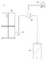
도 1은 본 발명의 일 실시 예에 따른 가전기기 진단시스템을 개략적으로 보여주는 도면.
도 2는 본 발명의 일 실시 예에 따른 가전기기 진단시스템의 블록도.
도 3은 본 발명의 일 실시 예에 따른 외부서버의 진단과정을 보여주는 흐름도.
도 4는 가전기기의 이상유무 판단을 설명하기 위해 가전기기 소비 전력값의 일 예를 도시한 도표.BRIEF DESCRIPTION OF THE DRAWINGS FIG. 1 is a schematic view of a household appliance diagnostic system according to an embodiment of the present invention; FIG.
2 is a block diagram of a home appliance diagnostic system in accordance with an embodiment of the present invention.
3 is a flowchart illustrating a diagnostic process of an external server according to an exemplary embodiment of the present invention.
4 is a chart showing an example of the electric power consumption value of the household appliance for explaining an abnormality determination of the household appliance.
이하, 첨부된 도면을 참조하여 본 명세서에 개시된 실시 예를 상세히 설명하되, 도면 부호에 관계없이 동일하거나 유사한 구성요소는 동일한 참조 번호를 부여하고 이에 대한 중복되는 설명은 생략하기로 한다. 이하의 설명에서 사용되는 구성요소에 대한 접미사 "모듈" 및 "부"는 명세서 작성의 용이함만이 고려되어 부여되거나 혼용되는 것으로서, 그 자체로 서로 구별되는 의미 또는 역할을 갖는 것은 아니다. 또한, 본 명세서에 개시된 실시 예를 설명함에 있어서 관련된 공지 기술에 대한 구체적인 설명이 본 명세서에 개시된 실시 예의 요지를 흐릴 수 있다고 판단되는 경우 그 상세한 설명을 생략한다. 또한, 첨부된 도면은 본 명세서에 개시된 실시 예를 쉽게 이해할 수 있도록 하기 위한 것일 뿐, 첨부된 도면에 의해 본 명세서에 개시된 기술적 사상이 제한되지 않으며, 본 발명의 사상 및 기술 범위에 포함되는 모든 변경, 균등물 내지 대체물을 포함하는 것으로 이해되어야 한다.Hereinafter, embodiments of the present invention will be described in detail with reference to the accompanying drawings, wherein like reference numerals are used to designate identical or similar elements, and redundant description thereof will be omitted. The suffix "module" and " part "for the components used in the following description are given or mixed in consideration of ease of specification, and do not have their own meaning or role. In the following description of the embodiments of the present invention, a detailed description of related arts will be omitted when it is determined that the gist of the embodiments disclosed herein may be blurred. It is to be understood that both the foregoing general description and the following detailed description are exemplary and explanatory and are intended to provide further explanation of the invention as claimed. , ≪ / RTI > equivalents, and alternatives.
도 1은 본 발명의 일 실시 예에 따른 가전기기 진단시스템을 개략적으로 보여주는 도면이고, 도 2는 본 발명의 일 실시 예에 따른 가전기기 진단시스템의 블록도 이다.FIG. 1 is a schematic view of a household appliance diagnostic system according to an embodiment of the present invention, and FIG. 2 is a block diagram of a home appliance diagnostic system according to an embodiment of the present invention.
도 1 및 도 2를 참조하면, 본 발명의 일 실시 예에 따른 가전기기 진단시스템(10)은, 가전기기(100)와, 상기 가전기기(100)의 전력 정보를 감지하는 스마트 플러그(200)와, 상기 스마트 플러그(200)에서 획득한 전력 정보를 기초로 상기 가전기기(100)의 상태를 진단하는 외부서버(300)와, 상기 외부서버(300)에서 감지된 상기 가전기기(100)의 상태 결과를 수신하는 단말기(400)를 포함한다.1 and 2, a home
상기 가전기기(100)는, 냉장고, 조리기기, 세탁기, 청소기, 정수기, 공기조화기 등 다양한 제품을 포함할 수 있으며, 본 명세서에서 가전기기(100)의 종류에는 제한이 없음을 밝혀둔다.The
상기 가전기기(100)는, 제 1 제어부(110), 표시부(120), 전원부(130), 감지부(140)를 포함할 수 있다. 상기 구성요소들은 상기 가전기기(100)를 구현하는데 있어서 필수적인 것은 아니어서, 본 명세서 상에서 설명되는 상기 가전기기(100)는 위에서 열거된 구성요소들 보다 많거나, 또는 적은 구성요소들을 가질 수 있다.The
상기 제 1 제어부(110)는 상기 가전기기(100)의 전반적인 동작을 제어한다. 상기 제 1 제어부(110)는 상기 가전기기(100)의 구성요소들을 통해 입력 또는 출력되는 신호, 데이터, 정보 등을 처리하거나 구동함으로써, 상기 가전기기(100)의 구동을 위한 적절한 정보 또는 기능을 제공 또는 처리할 수 있다.The
상기 표시부(120)는, 상기 가전기기(100)의 작동 및 상태에 대한 정보를 표시한다. 상기 작동 및 상태에 대한 정보는 고장에 대한 정보, 운전 상태에 대한 정보, 다른 구성요소로부터 전달받은 정보 등을 포함할 수 있다. 상기 표시부(120)의 표시는 외관에 구비된 디스플레이 화면 또는 스피커를 통해 출력되는 음성 메시지를 통해 이루어질 수 있다. 또한, 상기 표시부(120)의 표시(음성 출력 또는 LED 동작)로 인해, 상기 가전기기(100)는 전력을 소모하게 되고, 상기 표시부(120)의 소비 전력값은 후술할 상기 스마트 플러그(200)에서 측정된다.The
상기 전원부(130)는 상기 가전기기(100)를 구동시키는 구성요소의 세기 및 전원 등을 제어한다. 일 예로, 상기 전원부(130)는 상기 가전기기(100)에서 전력을 소비하는 구성요소의 세기를 조절할 수 있다. 사용자는 상기 가전기기(100)의 동작을 제어하는 조작부(미도시)를 통해 상기 전원부(130)의 온/ 오프를 제어할 수 있다.The power supply unit 130 controls the intensity of a component that drives the
상기 감지부(140)는 상기 가전기기(100)의 이상유무를 감지하는 구성으로써, 상기 가전기기(100)의 내, 외부에 설치되는 다수의 센서 또는 진단 장치의 형태로 구성될 수 있다. 여기서, 상기 가전기기(100)의 이상유무 감지라 함은, 상기 가전기기(100)의 작동에 있어 통상의 상태가 아닌 상태를 상기 감지부(140)가 감지하는 것을 말한다. 예를 들면, 상기 가전기기(100)가 냉장고일 경우, 상기 감지부(140)는 상기 냉장고의 도어에 구비되는 도어 감지센서일 수 있다. 따라서, 상기 감지부(140)에 의해 상기 도어의 열림이 감지될 시, 상기 제 1 제어부(110)는 상기 감지부(140)의 감지 결과를 상기 표시부(120)에 표시하여 사용자가 도어의 열림을 인지할 수 있도록 한다.The
상기 스마트 플러그(200)는 상기 가전기기(100)의 플러그에 덧끼워 전력 사용량 모니터링과 대기전력 차단 및 원격제어 기능을 제공하는 구성으로서, 제 2 제어부(210), 전력 공급부(220), 전력 측정부(230), 전력 차단부(240), 제 1 통신부(250) 및 진단부(260)를 포함할 수 있다.The SmartPlot 200 has a configuration for providing a function of monitoring power consumption and interrupting standby power and remote control by being inserted into a plug of the
상기 제 2 제어부(210)는 상기 스마트 플러그(200)의 전반적인 동작을 제어한다. 상기 제 2 제어부(210)는 상기 구성요소들을 통해 입력 또는 출력되는 신호, 데이터, 정보 등을 처리하거나 구동함으로써, 상기 스마트 플러그(100)의 구동을 위한 적절한 정보 또는 기능을 제공 또는 처리할 수 있다.The
상기 전력 공급부(220)는 세대 내 분전반으로부터 공급되는 전원을 콘센트에 공급하여 스마트플러그(200)에 연접한 상기 가전기기(100)에 전력을 공급한다.The
상기 전력 측정부(230)는 플러그를 통해 접속되어 있는 상기 가전기기(100)로 공급되는 전력 및 대기전력을 측정하는 측정부이다. 즉, 상기 전력 측정부(230)는 상기 전력 공급부(220)에서 상기 가전기기(100)로 공급되는 전력을 측정하여, 상기 가전기기(100)의 소모 전력을 판단한다. 상기 전력 측정부(230)에서 측정된 값은 상기 제 1 통신부(250)를 통해 상기 외부서버(300) 또는 상기 단말기(400)로 송신될 수 있다.The
상기 전력 차단부(240)는, 상기 스마트 플러그(200)가 상기 외부서버(300) 또는 상기 단말기(400)로부터 대기전력 차단 명령을 수신하거나 위험상황을 감지할 경우, 제 2 제어부(210)의 제어에 의해 스위치를 동작시켜 상기 가전기기(100)로 공급되는 전력을 차단 한다. 이 중 상기의 위험상황이라 함은, 상기 전력 측정부(230)로부터 측정된 상기 가전기기(100)의 소모 전력이 비정상이라고 판단된 경우이거나, 후술할 상기 진단부(260)에 의해 진단된 상기 가전기기(100)의 소모 전력 패턴이 불규칙적인 경우를 말한다.The
상기 제 1 통신부(250)는 상기 스마트 플러그(200)와 상기 외부서버(300) 사이, 상기 스마트 플러그(200)와 상기 단말기(400) 사이, 상기 스마트 플러그(200)와 상기 가전기기(100) 사이의 유, 무선 통신을 가능하게 하는 하나 이상의 모듈을 포함할 수 있다. 그리고, 상기 제 1 통신부(250)는 상기 스마트 플러그(200)를 하나 이상의 네트워크에 연결하는 하나 이상의 모듈을 포함할 수 있다. 따라서, 상기 제 1 통신부(250)를 통해 상기 스마트 플러그(200)는 상기 가전기기(100), 외부서버(300) 및 상기 단말기(400)와 통신할 수 있다. 그리고, 상기 스마트 플러그(200)은 상기 단말기(400)와 근거리 통신 모듈을 통해 통신할 수 있다. . 상기 근거리 통신 모듈은 근거리 통신(Short range communication)을 위한 것으로서, 블루투스(Bluetooth), RFID(Radio Frequency Identification), 적외선 통신(Infrared Data Association; IrDA), UWB(Ultra Wideband), ZigBee, NFC(Near Field Communication), Wi-Fi(Wireless-Fidelity), Wi-Fi Direct, Wireless USB(Wireless Universal Serial Bus) 기술 중 적어도 하나를 이용하여, 근거리 통신을 지원할 수 있다. 한편, 상기 스마트 플러그(200)가 구비되는 가정 내에는, 상기 제 1 통신부(250)의 통신을 가능하게 하는 통신장치(500, AP)가 설치될 수 있다.The
한편, 상기 가전기기(100)의 이상 상태 감지는, 상기 스마트 플러그(200)에서 수신되는 상기 가전기기(100)의 소비 전력 값이 특정 패턴을 형성함으로써 이루어질 수 있다. 상세히, 상기 진단부(140)에서 진단 결과 상기 가전기기(100)의 이상 동작이 감지될 경우, 상기 가전기기(100)에서 전력을 소비하는 부하에서는, 전력 소비에 있어 일정 패턴을 형성하게 되고, 상기 패턴화 된 전력값은 상기 스마트 플러그(200)에 의해 감지될 수 있다.Meanwhile, the abnormal state detection of the
일 예로 상기 전력 소비 부하는 상기 표시부(120)일 수 있다. 상기 표시부(120)는 전술한 바와 같이 이상 상태를 표시함에 있어, 일정 전력을 소비하게 된다. 이때, 상기 표시부(120)에서 소모되는 전력값이 특정 패턴을 형성함으로써, 상기 스마트 플러그(200)에 의해 감지될 수 있다.For example, the power consumption load may be the
예를 들어, 상기 표시부(120)가 빛을 발광하는 LED 램프일 경우, 켜짐과 꺼짐의 반복을 통해 상기 표시부(120)에서 소모되는 전력값은 특정 패턴을 형성하게 된다. 이와 달리, LED 램프에서 발광되는 빛의 세기를 가변시킴으로써, 상기 표시부(120)의 전력 소모가 패턴을 형성하도록 구성하는 것도 가능하다.For example, when the
상기 외부서버(300)는, 상기 가전기기(100)의 제조회사가 운영하거나 제조회사가 위탁한 회사가 운영하는 서버, 가전기기의 서비스를 위한 서버, 웹 서버 등을 포함할 수 있다. 본 명세서에서 상기 외부서버(300)의 종류에는 제한이 없다.The
상기 외부서버(300)는 이상 동작 감지부(310) 및 메모리(320)를 포함할 수 있다. The
상기 이상 동작 감지부(310)는 상기 스마트 플러그(200)로부터 수신되는 상기 가전기기(100)의 소비 전력값을 통해 상기 가전기기(100)의 이상 동작 감지, 기기 오류, 사용자의 가전기기(100) 오사용 여부 등을 판단한다. 상기 가전기기(100)의 소비 전력값을 통해 감지되는 이상 동작으로는, 전력을 제공받는 상기 가전기기(100)의 장기간 미사용 여부, 상기 가전기기(100)가 냉장고일 경우 미세 문열림으로 인한 소모 전력, 상기 가전기기(100)의 특정 구성요소의 과도한 동작으로 인한 전력 소모 등이 포함될 수 있다.The abnormal
상기 이상 동작 감지부(310)의 상기 가전기기(100)의 상태 판단은 상기 메모리(320)에 저장된 데이터를 기초로 판단될 수 있다. 이를 위해, 상기 메모리(320)에는 에너지 등급과 같은 상기 가전기기(100)의 소비 전력 정보 및 기준 전력값, 특정 사용자의 전력 사용 패턴, 가전기기의 오작동에 따른 전력 사용 패턴 등이 저장될 수 있다. 따라서, 상기 이상 동작 감지부(310)는 상기 스마트 플러그(200)로부터 수신되는 상기 가전기기(100)의 소비전력을 상기 메모리(320)에 저장된 값과 비교함으로써, 상기 가전기기(100)의 작동 상태를 판단할 수 있다. 상기 외부서버(300)가 전력값을 통해 상기 가전기기(100)의 작동 상태를 판단하는 상세한 과정에 대해서는 후술하기로 한다.The state determination of the
상기 단말기(400)는 사용자가 소지되는 휴대폰, 스마트 폰(smart phone), 노트북 컴퓨터(laptop computer), 디지털방송용 단말기, PDA(personal digital assistants), PMP(portable multimedia player), 네비게이션, 슬레이트 PC(slate PC), 태블릿 PC(tablet PC), 울트라북(ultrabook), 웨어러블 디바이스(wearable device, 예를 들어, 워치형 단말기 (smartwatch), 글래스형 단말기 (smart glass), HMD(head mounted display)) 등이 포함될 수 있다.The terminal 400 may be a mobile phone, a smart phone, a laptop computer, a digital broadcasting terminal, a personal digital assistant (PDA), a portable multimedia player (PMP), a navigation device, a slate PC PCs), tablet PCs, ultrabooks, wearable devices (e.g., smartwatches, smart glass, HMDs (head mounted displays), etc.) .
상기 단말기(400)은, 상기 단말기(400)의 기능 수행을 제어하는 제 3 제어부(410)와, 네트워크에 조인되어 통신할 수 있는 제 2 통신부(420)와, 사용자에 의해 명령이 입력되는 입력부(430)와, 상기 가전기기(400)에 상태에 관한 내용이 표시되는 디스플레이부(440)를 포함한다. 그리고, 상기 단말기(400)에는 상기 제 2 통신부(420)를 통해 상기 가전기기(100), 상기 스마트 플러그(200) 및 상기 외부서버(300)와 통신을 수행하여, 상기 가전기기(100)에 관한 정보를 수신하고 상기 가전기기(100)의 운전을 제어하기 위한 어플리케이션(450)이 설치된다.The terminal 400 includes a
따라서, 상기 단말기(400)는 상기 스마트 플러그(200)로부터 상기 가전기기(100)의 소비 전력에 관한 정보를 수신하고, 상기 외부서버(300)로부터 상기 가전기기(300) 상태에 관한 정보를 수신한다. 그리고, 사용자는 상기 수신되는 정보에 기초하여, 상기 가전기기(100)의 작동을 제어할 수 있다. 상기의 과정들은 상기 단말기(400)에 설치되는 상기 어플리케이션(450)을 통해 수행될 수 있다.Accordingly, the terminal 400 receives information on the power consumption of the
이하에서는, 상기 가전기기(100)의 이상 동작을 감지하고, 이를 해결하는 과정에 대해 설명하기로 한다.Hereinafter, a process of detecting an abnormal operation of the home
도 3은 본 발명의 일 실시 예에 따른 외부서버의 진단과정을 보여주는 흐름도 이고, 도 4는 가전기기의 이상유무 판단을 설명하기 위해 가전기기 소비 전력값의 일 예를 도시한 도표 이다.FIG. 3 is a flowchart illustrating a diagnostic process of an external server according to an exemplary embodiment of the present invention. FIG. 4 is a table illustrating an example of a power consumption value of a home appliance to explain an abnormality determination of the home appliance.
도 3을 참조하면, 먼저 상기 가전기기(100)이 전원이 ON되고, 상기 가전기기(100)는 사용자 제어 명령에 따른 특정 동작을 수행한다(S100). 이 때, 상기 스마트 플러그(200)의 전력 측정부(230)는 상기 가전기기(100)에서 소비되는 전력값을 측정하고, 이 값에 기초하여 상기 진단부(260)가 상기 가전기기(100)의 이상 여부를 진단할 수 있다.Referring to FIG. 3, the
다음으로, 상기 가전기기(100)에 구비되는 감지부(140)에 의해 상기 가전기기(100)의 이상 동작이 감지되고(S110), 상기 제 1 제어부(110)는 상기 표시부(120)에 상기 가전기기(100)의 이상 상태를 표시한다(S120). 예를 들어, 상기 가전기기(100)의 특정 구성 에러(Error) 발생 시, 상기 표시부(120)에는 상기 특정 구성에 대한 에러 정보가 표시될 수 있다.Next, the abnormal operation of the
전술한 바와 같이, 상기 표시부(120)의 이상 상태 표시로 인해, 상기 표시부(120)는 전력을 소모할 수 있다. 이때, 상기 표시부(120)의 소모 전력을 일정 패턴을 형성하게 된다. 도 4에 도시된 바와 같이, 상기 표시부(120)의 동작으로 인해 소비되는 전력 값을 1이라 하고, 상기 표시부(120)의 미 동작으로 인해 소비되는 전력 값을 0이라 하면, 상기 표시부(120)는 동작과 미동작을 교번되게 함으로써 상기 가전기기(100)의 이상 상태를 표시할 수 있다(A구간). 또는, 상기 표시부(120)는 연속 동작 및 연속 미 동작을 수행함으로써, 상기 가전기기(100)의 이상 상태를 표시할 수 도 있다(B구간).As described above, the
그리고, 상기 스마트 플러그(200)에는 상기 표시부(120)에서 소비한 패턴화 된 전력값이 수신된다(S140). 상세히 상기 표시부(120)의 패턴화 된 전력 소비로 인해, 상기 스마트 플러그(200)의 진단부(260)는 상기 전력 측정부(230)에서 측정한 상기 가전기기(100)의 소비 전력값 중 상기 표시부(120)의 패턴 전력값을 추출하여, 상기 가전기기(100)의 이상 여부를 판단한다. 이를 위해, 상기 스마트 플러그(200)에는, 상기 가전기기(100)의 이상 상황 발생 시 상기 표시부(120)의 이상 상태 표시에 관한 전력 패턴 값이 기저장될 수 있다.The patterned power value consumed by the
따라서, 상기 진단부(260)에 의해 상기 가전기기(100)의 이상 상황이 감지되면, 상기 스마트 플러그(200)는 상기 가전기기(100)의 전체 소비전력 값을 분석하여(S160), 사용자가 소지한 상기 단말기(400)로 상기 분석 값을 송신함으로써 사용자가 상기 가전기기(100)의 이상 상태를 인지하도록 한다. 사용자 알림은, 상기 단말기(400)에 표시되는 메시지(Message) 형태로서 전달될 수 있고, 사용자는 상기 단말기(400) 표시 내용을 통해 상기 가전기기(100)의 자가 진단을 조속히 수행할 수 있다(S170).The
만약, 상기 가전기기(100)의 제조회사가 운영하는 외부서버(300)가 있을 경우, 상기 스마트 플러그(200)는 상기 제 1 통신부(250)의 통신을 통해 상기 외부서버(300)로 상기 가전기기(100)의 전체 소비전력 값을 송신하고(S200), 상기 외부서버(300)의 이상동작 감지부(310)는 수신된 상기 가전기기(100)의 소비전력 값에 기초하여 상기 가전기기(100)의 이상동작을 진단한다(S210).If there is an
진단 결과, 상기 가전기기(100)가 이상 상태라고 판단될 경우, 상기 단말기(400)로 메시지를 송신함으로써 사용자에게 상기 가전기기(100)의 이상 상태를 인지시키고, 사용자는 마찬가지로 상기 가전기기(100)의 자가 진단을 수행함으로써 상기 가전기기(100)를 고장을 조기에 방지할 수 있다.
As a result of the diagnosis, when it is determined that the
Claims (12)
Translated fromKorean상기 가전기기의 플러그와 접속하여 상기 가전기기에서 소모되는 소비 전력값을 측정하는 스마트 플러그; 및
상기 스마트 플러그로부터 상기 가전기기의 상태 정보를 수신하는 사용자 단말기를 포함하며,
상기 감지부에 의해 상기 가전기기의 이상 상태가 감지될 경우, 상기 가전기기는 부하를 제어하여 소모되는 소비 전력값의 패턴(pattern)을 형성하고,
상기 스마트 플러그는, 상기 패턴화 된 소비 전력값에 기초하여 감지한 상기 가전기기의 상태 정보를 상기 단말기로 송신하는 것을 특징으로 하는 가전기기 진단시스템.
A home appliance having a sensing unit for sensing whether an operation or a state is abnormal;
A smart plug connected to the plug of the home appliance to measure a power consumption value consumed in the home appliance; And
And a user terminal for receiving status information of the home appliance from the smart plug,
When the abnormal state of the home appliance is detected by the sensing unit, the home appliance controls a load to form a pattern of consumed power values,
And the smart plug transmits the state information of the home appliance, which is sensed based on the patterned power consumption value, to the terminal.
상기 가전기기는 상기 가전기기의 작동 및 상태에 관한 정보를 표시하는 표시부를 더 포함하고,
상기 소비 전력값의 패턴은, 상기 표시부에서 소모되는 전력값이 조절됨으로써 형성되는 가전기기 진단시스템.
The method according to claim 1,
Wherein the household appliance further comprises a display section for displaying information on an operation and a state of the household appliance,
Wherein the pattern of the power consumption value is formed by adjusting a power value consumed by the display unit.
상기 표시부는 빛을 발광하는 램프를 포함하고,
상기 램프는, 꺼짐과 켜짐의 반복 또는 발광되는 빛의 세기를 가변시킴으로써, 소비 전력값의 패턴을 형성하는 가전기기 진단시스템.
3. The method of claim 2,
Wherein the display unit includes a lamp that emits light,
Wherein the lamp forms a pattern of power consumption values by repeatedly turning on and off or varying intensity of emitted light.
상기 스마트 플러그와 통신 가능하게 연결되며, 상기 스마트 플러그로부터 수신되는 전력 정보를 기초로 상기 가전기기의 이상 여부를 감지하는 외부서버를 더 포함하고,
상기 외부서버는, 수신한 상기 패턴화 된 소비 전력값 또는 상기 가전기기의 소비 전력값에 기초하여 상기 가전기기의 상태 정보를 판단하는 가전기기 진단시스템.
The method according to claim 1,
Further comprising an external server communicably connected to the smart plug for detecting an abnormality of the home appliance based on power information received from the smart plug,
Wherein the external server determines the state information of the household appliance based on the received pattern power consumption value or the power consumption value of the household appliance.
상기 외부서버에서 판단된 상기 가전기기의 상태 정보는 상기 단말기로 수신되는 것을 특징으로 하는 가전기기 진단시스템.
5. The method of claim 4,
And the state information of the home appliance determined by the external server is received by the terminal.
상기 가전기기의 플러그와 접속하여 상기 가전기기에서 소모되는 소비 전력값을 측정하는 스마트 플러그;
상기 스마트 플러그와 통신 가능하게 연결되며, 상기 스마트 플러그로부터 상기 가전기기의 소비 전력값을 수신하는 외부서버; 및
상기 외부서버로부터 상기 가전기기의 상태 정보를 수신하는 사용자 단말기를 포함하며,
상기 감지부에 의해 상기 가전기기의 이상 상태가 감지될 경우, 상기 가전기기는 부하를 제어하여 소모되는 소비 전력값의 패턴(pattern)을 형성하고,
상기 외부서버는, 수신한 상기 패턴화 된 소비 전력값 또는 상기 가전기기의 소비 전력값에 기초하여 상기 가전기기의 상태 정보를 판단하는 가전기기 진단시스템.
A home appliance having a sensing unit for sensing whether an operation or a state is abnormal;
A smart plug connected to the plug of the home appliance to measure a power consumption value consumed in the home appliance;
An external server communicably connected to the smart plug and receiving power consumption values of the home appliances from the smart plug; And
And a user terminal for receiving status information of the home appliance from the external server,
When the abnormal state of the home appliance is detected by the sensing unit, the home appliance controls a load to form a pattern of consumed power values,
Wherein the external server determines the state information of the household appliance based on the received pattern power consumption value or the power consumption value of the household appliance.
상기 가전기기는 상기 가전기기의 작동 및 상태에 관한 정보를 표시하는 표시부를 더 포함하고,
상기 소비 전력값의 패턴은, 상기 표시부에서 소모되는 전력값이 조절됨으로써 형성되는 가전기기 진단시스템.
The method according to claim 6,
Wherein the household appliance further comprises a display section for displaying information on an operation and a state of the household appliance,
Wherein the pattern of the power consumption value is formed by adjusting a power value consumed by the display unit.
상기 표시부는 빛을 발광하는 램프를 포함하고,
상기 램프는, 꺼짐과 켜짐의 반복 또는 발광되는 빛의 세기를 가변시킴으로써, 소비 전력값의 패턴을 형성하는 가전기기 진단시스템.
8. The method of claim 7,
Wherein the display unit includes a lamp that emits light,
Wherein the lamp forms a pattern of power consumption values by repeatedly turning on and off or varying intensity of emitted light.
상기 외부서버에서 판단된 상기 가전기기의 상태 정보는 상기 단말기로 수신되는 것을 특징으로 하는 가전기기 진단시스템.
The method according to claim 6,
And the state information of the home appliance determined by the external server is received by the terminal.
상기 가전기기의 이상 상태 감지 시, 상기 가전기기의 특정 부하가 일정 패턴의 소비 전력을 소모하는 단계;
상기 가전기기와 전기적으로 접속된 스마트 플러그에 의해 상기 일정 패턴의 소비 전력이 측정되는 단계; 및
상기 스마트 플러그가 사용자의 단말기로 상기 가전기기의 이상 상태를 송신하는 단계를 포함하는 가전기기 진단시스템의 진단방법.
Detecting an abnormal state of the home appliance by the sensing unit;
When the abnormal state of the home appliance is detected, the specific load of the home appliance consumes a predetermined pattern of power consumption;
Measuring a power consumption of the predetermined pattern by a smart plug electrically connected to the home appliance; And
Wherein the smart plug transmits an abnormal state of the home appliance to a user's terminal.
상기 스마트 플러그에 의해 측정된 상기 일정 패턴의 소비 전력 정보는, 상기 스마트 플러그와 통신 가능하게 연결되는 외부 서버로 송신되는 단계를 더 포함하는 가전기기 진단시스템의 진단방법.
11. The method of claim 10,
Wherein the predetermined pattern of power consumption information measured by the smart plug is transmitted to an external server communicably connected to the smart plug.
상기 가전기기는 상기 가전기기의 작동 및 상태에 관한 정보를 표시하는 표시부를 더 포함하고,
상기 소비 전력값의 패턴은, 상기 표시부에서 소모되는 전력값이 조절됨으로써 형성되는 가전기기 진단시스템의 진단방법.
11. The method of claim 10,
Wherein the household appliance further comprises a display section for displaying information on an operation and a state of the household appliance,
Wherein the pattern of the power consumption value is formed by adjusting a power value consumed in the display unit.
Priority Applications (1)
| Application Number | Priority Date | Filing Date | Title |
|---|---|---|---|
| KR1020150103136AKR101718222B1 (en) | 2015-07-21 | 2015-07-21 | Diagnostic system and method for home appliance |
Applications Claiming Priority (1)
| Application Number | Priority Date | Filing Date | Title |
|---|---|---|---|
| KR1020150103136AKR101718222B1 (en) | 2015-07-21 | 2015-07-21 | Diagnostic system and method for home appliance |
Publications (2)
| Publication Number | Publication Date |
|---|---|
| KR20170011129Atrue KR20170011129A (en) | 2017-02-02 |
| KR101718222B1 KR101718222B1 (en) | 2017-03-20 |
Family
ID=58151691
Family Applications (1)
| Application Number | Title | Priority Date | Filing Date |
|---|---|---|---|
| KR1020150103136AActiveKR101718222B1 (en) | 2015-07-21 | 2015-07-21 | Diagnostic system and method for home appliance |
Country Status (1)
| Country | Link |
|---|---|
| KR (1) | KR101718222B1 (en) |
Cited By (5)
| Publication number | Priority date | Publication date | Assignee | Title |
|---|---|---|---|---|
| CN107271764A (en)* | 2017-06-19 | 2017-10-20 | 宁波三星医疗电气股份有限公司 | A kind of electrical appliance power consumption method for detecting abnormality and device |
| IT201800006543A1 (en)* | 2018-06-22 | 2018-09-22 | Method for checking the operation of a door-lock device and related control system. | |
| KR102012933B1 (en)* | 2018-02-22 | 2019-08-21 | 한전케이디엔 주식회사 | Smart home system |
| KR102092522B1 (en)* | 2018-10-15 | 2020-05-22 | (주)미래정보통신컨설팅 | Smart apparatus and system for monitoring electric power |
| KR102149383B1 (en)* | 2019-11-07 | 2020-08-31 | 주식회사 유비벨록스모바일 | System for polysynthetically managing information of smart home appliances based on big data |
Citations (4)
| Publication number | Priority date | Publication date | Assignee | Title |
|---|---|---|---|---|
| KR20010011042A (en)* | 1999-07-24 | 2001-02-15 | 윤종용 | Refrigerator and controlling method thereof |
| KR20100063630A (en)* | 2008-12-03 | 2010-06-11 | 한국전자통신연구원 | Method and system for collecting power consumption according to operation of electric device |
| KR20120133922A (en)* | 2011-06-01 | 2012-12-11 | 연세대학교 산학협력단 | Smart plug and power quality monitoring system thereof |
| KR20130048358A (en)* | 2011-11-02 | 2013-05-10 | 주식회사 씨브이네트 | System for monitoring the electric power using the smart consent |
- 2015
- 2015-07-21KRKR1020150103136Apatent/KR101718222B1/enactiveActive
Patent Citations (4)
| Publication number | Priority date | Publication date | Assignee | Title |
|---|---|---|---|---|
| KR20010011042A (en)* | 1999-07-24 | 2001-02-15 | 윤종용 | Refrigerator and controlling method thereof |
| KR20100063630A (en)* | 2008-12-03 | 2010-06-11 | 한국전자통신연구원 | Method and system for collecting power consumption according to operation of electric device |
| KR20120133922A (en)* | 2011-06-01 | 2012-12-11 | 연세대학교 산학협력단 | Smart plug and power quality monitoring system thereof |
| KR20130048358A (en)* | 2011-11-02 | 2013-05-10 | 주식회사 씨브이네트 | System for monitoring the electric power using the smart consent |
Cited By (8)
| Publication number | Priority date | Publication date | Assignee | Title |
|---|---|---|---|---|
| CN107271764A (en)* | 2017-06-19 | 2017-10-20 | 宁波三星医疗电气股份有限公司 | A kind of electrical appliance power consumption method for detecting abnormality and device |
| CN107271764B (en)* | 2017-06-19 | 2020-05-12 | 宁波三星医疗电气股份有限公司 | Method and device for detecting abnormal power consumption of electrical appliance |
| KR102012933B1 (en)* | 2018-02-22 | 2019-08-21 | 한전케이디엔 주식회사 | Smart home system |
| IT201800006543A1 (en)* | 2018-06-22 | 2018-09-22 | Method for checking the operation of a door-lock device and related control system. | |
| EP3587712A1 (en)* | 2018-06-22 | 2020-01-01 | Bitron S.p.A. | Method for controlling the operation of a door-lock device and control system thereof |
| US11459793B2 (en) | 2018-06-22 | 2022-10-04 | Bitron S.P.A. | Method for controlling the operation of a door-lock device and control system thereof |
| KR102092522B1 (en)* | 2018-10-15 | 2020-05-22 | (주)미래정보통신컨설팅 | Smart apparatus and system for monitoring electric power |
| KR102149383B1 (en)* | 2019-11-07 | 2020-08-31 | 주식회사 유비벨록스모바일 | System for polysynthetically managing information of smart home appliances based on big data |
Also Published As
| Publication number | Publication date |
|---|---|
| KR101718222B1 (en) | 2017-03-20 |
Similar Documents
| Publication | Publication Date | Title |
|---|---|---|
| KR101708992B1 (en) | Diagnostic system and method for home appliance | |
| KR101718222B1 (en) | Diagnostic system and method for home appliance | |
| JP2010528365A (en) | Industrial field device with reduced power consumption | |
| CN103477328B (en) | Terminal device, control device, malfunction determination system, and method for determining malfunction | |
| JP2011227715A (en) | Detector, abnormality monitoring system, and program | |
| JP2016139303A (en) | Alarm | |
| KR20150087039A (en) | Network Camera System with Self-Diagnosis and Self-Diagnosis Method of Network Camera System | |
| JP2007132804A (en) | Power consumption checking system | |
| JP2015056875A (en) | Radio communication system and radio controller | |
| JP5844666B2 (en) | HART communication compatible equipment | |
| KR20240082427A (en) | Arc detector capable of diagnosing and predicting electric control panel fire | |
| KR20190068077A (en) | Sensor expandable wireless monitoring system | |
| JP5723645B2 (en) | Transfer output device | |
| JP2018010346A (en) | Detection device, detection system, and detection system construction method | |
| JP5331653B2 (en) | Alarm | |
| JP4801768B2 (en) | Alarm | |
| JP2013120522A (en) | Alarm | |
| KR20090109655A (en) | Battery check device of television remote control and its control method | |
| US20190394817A1 (en) | Method and apparatus for home monitoring and control system setup | |
| JP7172735B2 (en) | remote control system | |
| KR101767471B1 (en) | Intelligent Power Supplying Device | |
| JP2020085540A (en) | Gas meter | |
| CN103675656B (en) | Switch testing supervising device | |
| JP6161471B2 (en) | Wireless communication system and wireless controller | |
| JP2016224833A (en) | Alarm |
Legal Events
| Date | Code | Title | Description |
|---|---|---|---|
| A201 | Request for examination | ||
| PA0109 | Patent application | Patent event code:PA01091R01D Comment text:Patent Application Patent event date:20150721 | |
| PA0201 | Request for examination | ||
| PE0902 | Notice of grounds for rejection | Comment text:Notification of reason for refusal Patent event date:20161026 Patent event code:PE09021S01D | |
| PG1501 | Laying open of application | ||
| E701 | Decision to grant or registration of patent right | ||
| PE0701 | Decision of registration | Patent event code:PE07011S01D Comment text:Decision to Grant Registration Patent event date:20170214 | |
| PR0701 | Registration of establishment | Comment text:Registration of Establishment Patent event date:20170314 Patent event code:PR07011E01D | |
| PR1002 | Payment of registration fee | Payment date:20170314 End annual number:3 Start annual number:1 | |
| PG1601 | Publication of registration | ||
| PR1001 | Payment of annual fee | Payment date:20200214 Start annual number:4 End annual number:4 | |
| PR1001 | Payment of annual fee | Payment date:20210210 Start annual number:5 End annual number:5 | |
| PR1001 | Payment of annual fee | Payment date:20220209 Start annual number:6 End annual number:6 | |
| PR1001 | Payment of annual fee | Payment date:20240207 Start annual number:8 End annual number:8 |