KR20170010682A - Method and apparatus for controlling output according to type of external output device - Google Patents
Method and apparatus for controlling output according to type of external output deviceDownload PDFInfo
- Publication number
- KR20170010682A KR20170010682AKR1020150102662AKR20150102662AKR20170010682AKR 20170010682 AKR20170010682 AKR 20170010682AKR 1020150102662 AKR1020150102662 AKR 1020150102662AKR 20150102662 AKR20150102662 AKR 20150102662AKR 20170010682 AKR20170010682 AKR 20170010682A
- Authority
- KR
- South Korea
- Prior art keywords
- connector
- external connector
- external
- contact
- terminals
- Prior art date
- Legal status (The legal status is an assumption and is not a legal conclusion. Google has not performed a legal analysis and makes no representation as to the accuracy of the status listed.)
- Granted
Links
Images


Classifications
- G—PHYSICS
- G06—COMPUTING OR CALCULATING; COUNTING
- G06F—ELECTRIC DIGITAL DATA PROCESSING
- G06F3/00—Input arrangements for transferring data to be processed into a form capable of being handled by the computer; Output arrangements for transferring data from processing unit to output unit, e.g. interface arrangements
- G06F3/16—Sound input; Sound output
- G06F3/162—Interface to dedicated audio devices, e.g. audio drivers, interface to CODECs
- H—ELECTRICITY
- H04—ELECTRIC COMMUNICATION TECHNIQUE
- H04R—LOUDSPEAKERS, MICROPHONES, GRAMOPHONE PICK-UPS OR LIKE ACOUSTIC ELECTROMECHANICAL TRANSDUCERS; DEAF-AID SETS; PUBLIC ADDRESS SYSTEMS
- H04R1/00—Details of transducers, loudspeakers or microphones
- H04R1/10—Earpieces; Attachments therefor ; Earphones; Monophonic headphones
- H04R1/1041—Mechanical or electronic switches, or control elements
- H—ELECTRICITY
- H04—ELECTRIC COMMUNICATION TECHNIQUE
- H04R—LOUDSPEAKERS, MICROPHONES, GRAMOPHONE PICK-UPS OR LIKE ACOUSTIC ELECTROMECHANICAL TRANSDUCERS; DEAF-AID SETS; PUBLIC ADDRESS SYSTEMS
- H04R5/00—Stereophonic arrangements
- H04R5/04—Circuit arrangements, e.g. for selective connection of amplifier inputs/outputs to loudspeakers, for loudspeaker detection, or for adaptation of settings to personal preferences or hearing impairments
- H—ELECTRICITY
- H01—ELECTRIC ELEMENTS
- H01R—ELECTRICALLY-CONDUCTIVE CONNECTIONS; STRUCTURAL ASSOCIATIONS OF A PLURALITY OF MUTUALLY-INSULATED ELECTRICAL CONNECTING ELEMENTS; COUPLING DEVICES; CURRENT COLLECTORS
- H01R24/00—Two-part coupling devices, or either of their cooperating parts, characterised by their overall structure
- H01R24/58—Contacts spaced along longitudinal axis of engagement
- H—ELECTRICITY
- H04—ELECTRIC COMMUNICATION TECHNIQUE
- H04R—LOUDSPEAKERS, MICROPHONES, GRAMOPHONE PICK-UPS OR LIKE ACOUSTIC ELECTROMECHANICAL TRANSDUCERS; DEAF-AID SETS; PUBLIC ADDRESS SYSTEMS
- H04R1/00—Details of transducers, loudspeakers or microphones
- H04R1/10—Earpieces; Attachments therefor ; Earphones; Monophonic headphones
- H—ELECTRICITY
- H04—ELECTRIC COMMUNICATION TECHNIQUE
- H04R—LOUDSPEAKERS, MICROPHONES, GRAMOPHONE PICK-UPS OR LIKE ACOUSTIC ELECTROMECHANICAL TRANSDUCERS; DEAF-AID SETS; PUBLIC ADDRESS SYSTEMS
- H04R29/00—Monitoring arrangements; Testing arrangements
- H04R29/001—Monitoring arrangements; Testing arrangements for loudspeakers
- H—ELECTRICITY
- H04—ELECTRIC COMMUNICATION TECHNIQUE
- H04R—LOUDSPEAKERS, MICROPHONES, GRAMOPHONE PICK-UPS OR LIKE ACOUSTIC ELECTROMECHANICAL TRANSDUCERS; DEAF-AID SETS; PUBLIC ADDRESS SYSTEMS
- H04R5/00—Stereophonic arrangements
- H04R5/02—Spatial or constructional arrangements of loudspeakers
- H—ELECTRICITY
- H04—ELECTRIC COMMUNICATION TECHNIQUE
- H04R—LOUDSPEAKERS, MICROPHONES, GRAMOPHONE PICK-UPS OR LIKE ACOUSTIC ELECTROMECHANICAL TRANSDUCERS; DEAF-AID SETS; PUBLIC ADDRESS SYSTEMS
- H04R2420/00—Details of connection covered by H04R, not provided for in its groups
- H04R2420/05—Detection of connection of loudspeakers or headphones to amplifiers
Landscapes
- Engineering & Computer Science (AREA)
- Physics & Mathematics (AREA)
- Acoustics & Sound (AREA)
- Signal Processing (AREA)
- Health & Medical Sciences (AREA)
- General Health & Medical Sciences (AREA)
- Otolaryngology (AREA)
- Circuit For Audible Band Transducer (AREA)
- Headphones And Earphones (AREA)
- Theoretical Computer Science (AREA)
- Multimedia (AREA)
- Audiology, Speech & Language Pathology (AREA)
- Human Computer Interaction (AREA)
- General Engineering & Computer Science (AREA)
- General Physics & Mathematics (AREA)
- Crystals, And After-Treatments Of Crystals (AREA)
- Analysing Materials By The Use Of Radiation (AREA)
Abstract
Translated fromKoreanDescription
Translated fromKorean본 개시의 다양한 실시 예는 외부 출력 장치의 유형을 기반으로 상기 외부 출력 장치를 지원하는 방법 및 이를 구현하는 전자장치에 관한 것이다.Various embodiments of the present disclosure are directed to a method of supporting the external output device based on the type of external output device and an electronic device implementing the same.
최근 들어, 스마트폰, 태블릿 PC, 디지털 카메라, MP3 플레이어, 전자책 등과 같은 전자장치의 이용은 일상적인 현상이다. 전자장치는 일반적으로 외부 출력 장치(예, 이어폰, 헤드셋)와 연결될 수 있으며, 유선 통화가 가능한 Unbalanced 타입(type)의 이어폰 출력을 지원할 수 있다. 일반적으로 전자장치는 외부 출력 장치에 내장된 마이크를 지원할 수 있으나, 외부 출력 장치에 마이크가 내장되지 않았더라도 언밸런스 오디오 신호의 출력을 지원할 수 있다. 전자장치는 일반적으로 이어폰의 커넥터(예, 이어잭)와 연결하기 위한 커넥터 연결부(예, 소켓, 리셉터클(receptacle))를 내장하고 있으며, 상기 이어폰의 이어잭은 4극 단자로 구성될 수 있다. 4극 단자는 유선 통화가 가능한 언밸런스(unbalanced) 타입의 이어폰을 지원하기 위한 표준 단자로 구성될 수 있다. 이어폰 타입은 언밸런스(unbalanced) 타입과 밸런스(balanced) 타입이 있을 수 있으며, balanced 타입의 이어폰이 unbalanced 타입보다 우수한 성능으로 오디오를 출력할 수 있다.In recent years, the use of electronic devices such as smart phones, tablet PCs, digital cameras, MP3 players, and e-books has been a common phenomenon. The electronic device may generally be connected to an external output device (e.g., earphone, headset) and may support an unbalanced type of earphone output capable of wired communication. Generally, an electronic device can support a microphone built in an external output device, but can support the output of an unbalanced audio signal even if the external output device does not have a built-in microphone. The electronic device generally includes a connector connection (for example, a socket, a receptacle) for connecting to a connector (e.g., an ear jack) of an earphone, and the ear jack of the earphone may be composed of a quadrupole terminal. The quadrupole terminal may be configured as a standard terminal for supporting an unbalanced type earphone capable of wired communication. Earphone type can be unbalanced type and balanced type, and balanced type earphone can output audio with better performance than unbalanced type.
전자장치에서 전송하는 오디오 신호는 balanced 타입의 오디오 신호와 unbalanced 타입의 오디오 신호로 구분될 수 있다. 전술된 두 개의 오디오 신호는 신호의 종류가 서로 다르므로, 서로 다르게 구성된 출력 단자를 필요로 한다. 예를 들어, unbalanced 타입의 오디오 신호는 R신호, L신호, G신호, M신호로 구성되나, balanced 타입의 오디오 신호는 L+신호, L-신호, R+신호, R-신호로 구성될 수 있다. 전자장치는 일반적으로 밸런스 타입 기반의 오디오 신호를 지원하지 않기 때문에, 밸런스 타입의 이어폰이나 헤드셋을 연결하더라도, 밸런스 타입에 따른 고품질의 오디오를 출력하기 어려운 경우가 많다.The audio signal transmitted from the electronic device can be divided into a balanced type audio signal and an unbalanced type audio signal. Since the two audio signals described above have different types of signals, they require differently configured output terminals. For example, an unbalanced type audio signal is composed of an R signal, an L signal, a G signal, and an M signal, but a balanced type audio signal may be composed of an L + signal, an L signal, an R + signal, and an R signal. Since electronic devices generally do not support balanced type based audio signals, it is often difficult to output high quality audio according to the balance type even if a balanced type earphone or headset is connected.
한편, 밸런스 타입의 출력 장치(예, 이어폰, 헤드셋)를 지원하기 위해서 컨버터(Converter) 장치가 추가적으로 필요할 수 있다. 즉, 전자장치가 밸런스 타입의 출력 장치와 호환하려면, 별도의 컨버터 장치를 필요로 한다. 별도의 컨버터 장치는 전자장치로부터 unbalanced(언밸런스) 오디오 신호를 수신하여, 별도의 컨버터 장치에 포함된 차등 증폭기를 통해 right 채널(오른쪽 출력부)이나 left 채널(왼쪽 출력부)의 신호를 플러스(plus, +)와 마이너스(minus, -)로 위상 반전하여 출력할 수 있다. 즉, 전자장치가 밸런스 타입의 출력 장치를 지원하기 위해서, 전자장치는 별도의 컨버터 장치를 필요로 할 수 있다.On the other hand, a converter device may be additionally required to support a balanced type output device (e.g., earphone, headset). That is, in order for an electronic device to be compatible with a balanced type output device, a separate converter device is required. The separate converter device receives an unbalanced audio signal from the electronic device and outputs the signal of the right channel (right output portion) or the left channel (left output portion) through the differential amplifier included in the separate converter device to plus , +) And minus (minus, -). That is, in order for an electronic device to support a balanced type output device, the electronic device may require a separate converter device.
본 발명의 다양한 실시예에 따른 전자장치는 별도의 컨버터 장치 연결 없이, 오디오 출력 장치(예, balanced 타입, unbalanced 타입)가 연결되는 경우 상기 오디오 출력 장치를 기반으로 전자장치의 회로 구성을 변경할 수 있다. 즉, 다양한 실시예에 따른 전자장치는 별도의 컨버터 장치 연결 없이, 밸런스 타입과 언밸런스 타입의 오디오 출력을 모두 지원하는 방법을 제공할 수 있다.An electronic device according to various embodiments of the present invention can change the circuit configuration of an electronic device based on the audio output device when an audio output device (e.g., a balanced type, unbalanced type) is connected, without connecting a separate converter device . That is, the electronic device according to various embodiments can provide a method of supporting both balanced type and unbalanced type audio output without connecting a separate converter device.
추가적으로, 본 발명의 다양한 실시예에 따른 전자장치는 4극 이어잭에 한정되는 것이 아니라, 3극이나 5극 이어잭에 대해서도 유형에 따라 회로 구성을 변경하여 적합한 오디오 출력을 지원할 수 있다. 또한, 전자장치는 마이크 기능을 제공하는 경우에도 밸런스 타입과 언밸런스 타입, 두 개의 오디오 출력을 모두 지원할 수 있다.In addition, the electronic device according to various embodiments of the present invention is not limited to a four-pole ear jack, but can also support a suitable audio output by changing the circuit configuration according to the type of the three-pole or five-pole ear jack. In addition, the electronic device can support both balanced and unbalanced audio outputs, even when providing a microphone function.
본 개시의 다양한 실시 예에 따른 저장장치는, 하우징; 상기 하우징의 일면에 형성된 개구; 상기 개구와 이어진 홀; 상기 홀 내부에 배치되고, 제 1 외부 커넥터 또는 제 2 외부 커넥터 중 어느 하나를 수용할 수 있도록 구성된 리셉터클(receptacle); 및 상기 리셉터클과 전기적으로 연결된 회로를 포함하고, 상기 제 1 외부 커넥터는 제 1 내지 제 4 단자를 포함하고, 상기 제 2 외부 커넥터는 상기 제 1 외부 커넥터와 실질적으로 동일한 배치로 제 1 내지 제 4 단자를 포함하고, 상기 회로는 상기 제 1 또는 제 2 외부 커넥터가 상기 리셉터클에 삽입되었는지를 검출하고, 상기 검출 결과에 따라, 상기 제 1 외부 커넥터가 삽입된 경우, 제 1 방식으로 오디오 출력을 상기 제 1 외부 커넥터에 제공하고, 상기 제 2 외부 커넥터가 삽입된 경우, 상기 제 1방식과 상이한 제 2 방식으로 오디오 출력을 상기 제 2 외부 커넥터에 제공하도록 구성되는 것을 특징으로 할 수 있다.A storage device according to various embodiments of the present disclosure includes: a housing; An opening formed on one surface of the housing; A hole connected to said opening; A receptacle disposed within the hole, the receptacle configured to receive either a first external connector or a second external connector; And a circuit electrically connected to the receptacle, wherein the first external connector includes first to fourth terminals, and the second external connector includes first to fourth terminals in substantially the same arrangement as the first external connector, Wherein the circuit detects whether the first or second external connector is inserted into the receptacle, and when the first external connector is inserted according to the detection result, And to provide the audio output to the second external connector in a second manner different from the first mode when the second external connector is inserted.
본 발명의 다양한 실시예에 따른 전자장치는 언밸런스 타입뿐만 아니라, 밸런스 타입의 출력 장치도 같이 지원하므로, 사용자의 편의성을 증대시킬 수 있다. 특히, 밸런스 타입의 출력 장치 지원으로 인해, 사용자는 보다 고품질의 오디오를 들을 수 있다.The electronic device according to various embodiments of the present invention can support not only an unbalanced type but also a balanced type output device, thereby enhancing convenience for the user. In particular, with the support of balanced output devices, users can hear higher quality audio.
도 1은 본 발명의 다양한 실시예에 따른 밸런스 타입(balanced type) 이어폰에 대한 예시도이다.
도 2a와 2b는 본 발명의 다양한 실시예에 따른 언밸런스 타입(unbalanced type)의 커넥터와 밸런스 타입(balanced type)의 커넥터에 대한 예시도이다.
도 3은 본 발명의 다양한 실시예에 따른 언밸런스 타입을 지원하는 전자장치에 밸런스 타입의 4극 커넥터가 연결된 경우 오디오가 출력되는 과정을 설명하기 위한 예시도이다.
도 4는 본 발명의 다양한 실시예에 따른 언밸런스 타입을 지원하는 전자장치에 밸런스 타입의 3극 이어폰이 연결된 경우 오디오가 출력되는 과정을 설명하기 위한 예시도이다.
도 5는 본 발명의 다양한 실시예에 따른 전자장치의 블록도이다.
도 6a은 본 발명의 다양한 실시예에 따른 연결된 외부 출력 장치 커넥터의 구성을 확인한 후 상기 커넥터의 구성에 대응하여 결정된 회로를 통해 오디오를 출력하는 방법을 설명하기 위한 순서도이다.
도 6b는 본 발명의 다양한 실시예에 따른 연결된 외부 출력 장치의 유형과 외부 출력 장치의 커넥터 구성을 확인하는 방법을 구체적으로 도식화한 순서도이다.
도 7은 본 발명의 다양한 실시예에 따른 연결된 외부 출력 장치가 밸런스 타입이냐, 언밴런스 타입이냐에 따라 다른 회로가 결정되는 방법을 설명하기 위한 순서도이다.
도 8a와 8b는 본 발명의 다양한 실시예에 따른 언밸런스 타입의 커넥터와의 호환성을 고려한 밸런스 타입의 커넥터 구성에 대한 예시도이다.
도 9는 본 발명의 다양한 실시예에 따른 밸런스 타입의 출력 장치가 전자장치에 연결된 경우 전자장치의 동작에 대한 예시도이다.
도 10은 본 발명의 다양한 실시예에 따른 밸런스 타입의 출력 장치가 전자장치에 연결된 경우 출력 장치에 대한 임피던스 및 전압를 측정하기 위한 전자장치의 동작에 대한 예시도이다.
도 11은 본 발명의 다양한 실시예에 따른 여러 종류로 구성된 밸런스 타입의 출력 장치 구성에 대한 예시도이다.
도 12는 본 발명의 다양한 실시예에 따른 여러 종류로 구성된 밸런스 타입의 출력 장치 커넥터가 전자장치에 연결된 경우 전자장치의 동작에 대한 예시도이다.
도 13은 본 발명의 다양한 실시예에 따른 4극 밸런스 타입의 출력 장치에 마이크가 포함되는 경우 출력 장치 구성에 대한 예시도이다.
도 14a와 14b는 본 발명의 다양한 실시예에 따른 5극 커넥터가 전자장치에 연결된 경우 전자장치의 동작을 설명하기 위한 흐름도이다.
도 15a와 15b는 본 발명의 다양한 실시예에 따른 5극 밸런스 타입의 커넥터 예시도와 상기 5극 밸런스 타입의 커넥터가 전자장치에 연결된 상태에 대한 예시도이다.
도 16은 본 발명의 다양한 실시예에 따른 5극 밸런스 타입의 커넥터가 전자장치에 연결된 경우 전자장치의 동작에 대한 예시도이다.
도 17은 본 발명의 다양한 실시예에 따른 5극 밸런스 타입의 커넥터가 전자장치에 연결된 경우 전자장치의 동작에 대한 다른 예시도이다.1 is an exemplary diagram of a balanced type earphone according to various embodiments of the present invention.
2A and 2B illustrate an unbalanced type connector and a balanced type connector according to various embodiments of the present invention.
FIG. 3 is a diagram illustrating a process of outputting audio when a balanced type four-pole connector is connected to an electronic device that supports an unbalanced type according to various embodiments of the present invention.
FIG. 4 is a diagram illustrating a process of outputting audio when a balanced type three-pole earphone is connected to an electronic device that supports an unbalanced type according to various embodiments of the present invention.
5 is a block diagram of an electronic device according to various embodiments of the present invention.
6A is a flowchart illustrating a method of outputting audio through a circuit determined in accordance with the configuration of the connector after confirming the configuration of a connected external output device connector according to various embodiments of the present invention.
6B is a flowchart illustrating a method of confirming the type of the connected external output device and the connector configuration of the external output device according to various embodiments of the present invention.
FIG. 7 is a flowchart illustrating a method of determining a different circuit depending on whether a connected external output device according to various embodiments of the present invention is a balance type or an unvary type.
8A and 8B are diagrams for illustrating a balance type connector configuration considering compatibility with an unbalanced type connector according to various embodiments of the present invention.
9 is an exemplary diagram of the operation of an electronic device when a balanced type output device according to various embodiments of the present invention is connected to the electronic device.
10 is an illustration of the operation of an electronic device for measuring impedance and voltage to an output device when a balanced type output device according to various embodiments of the present invention is connected to the electronic device.
11 is a diagram illustrating an example of a configuration of a balanced output apparatus of various types according to various embodiments of the present invention.
Figure 12 is an exemplary view of the operation of an electronic device when multiple types of balanced output device connectors are connected to the electronic device in accordance with various embodiments of the present invention.
13 is an exemplary diagram illustrating an output device configuration when a microphone is included in a quadrupole balance type output device according to various embodiments of the present invention.
14A and 14B are flow charts illustrating the operation of an electronic device when a five-pole connector according to various embodiments of the present invention is connected to the electronic device.
FIGS. 15A and 15B illustrate examples of a 5-pole balanced type connector according to various embodiments of the present invention and a state in which the 5-pole balanced type connector is connected to an electronic device.
16 is an exemplary view of the operation of an electronic device when a 5-pole balance type connector according to various embodiments of the present invention is connected to the electronic device.
17 is another exemplary view of the operation of the electronic device when the 5-pole balance type connector according to various embodiments of the present invention is connected to the electronic device.
이하, 본 발명의 다양한 실시예가 첨부된 도면과 연관되어 기재된다. 다양한 실시예는 다양한 변경을 가할 수 있고 여러 가지 실시예를 가질 수 있는 바, 특정 실시예들이 도면에 예시되고 관련된 상세한 설명이 기재되어 있다. 그러나, 이는 다양한 실시예를 특정한 실시 형태에 대해 한정하려는 것이 아니며, 다양한 실시예의 사상 및 기술 범위에 포함되는 모든 변경(modifications) 및/또는 균등물(equivalents) 내지 대체물(alternatives)을 포함하는 것으로 이해되어야 한다. 도면의 설명과 관련하여, 유사한 구성요소에 대해서는 유사한 참조부호가 사용되었다.Best Mode for Carrying Out the Invention Various embodiments of the present invention will be described below with reference to the accompanying drawings. The various embodiments are capable of various modifications and may have various embodiments, and specific embodiments are illustrated in the drawings and described in the detailed description. It will be understood, however, that it is not intended to limit the embodiments to the particular embodiments, but, on the contrary, is intended to cover all modifications and equivalents or alternatives falling within the spirit and scope of the various embodiments. . In connection with the description of the drawings, like reference numerals have been used for like elements.
다양한 실시예에서 사용되는 구성요소에 대한 접미사 “모듈” 및 “부”는 단순히 본 명세서 작성의 용이함만이 고려되어 부여되는 것으로서, 그 자체로 특별히 중요한 의미 또는 역할을 부여하는 것은 아니다. 따라서, 상기 “모듈” 및 “부”는 서로 혼용되어 사용될 수도 있음을 유념해야 한다.The suffix " module " and " part " for components used in various embodiments are given only for convenience of description, and do not give special significance or role in themselves. Accordingly, it should be noted that the above-mentioned " module " and " part "
다양한 실시예에서 사용될 수 있는“포함한다” 또는“포함할 수 있다” 등의 표현은 개시(disclosure)된 해당 기능, 동작 또는 구성요소 등의 존재를 가리키며, 추가적인 하나 이상의 기능, 동작 또는 구성요소 등을 제한하지 않는다. 또한, 본 발명의 다양한 실시예에서, "포함하다" 또는 "가지다" 등의 용어는 명세서상에 기재된 특징, 숫자, 단계, 동작, 구성요소, 부품 또는 이들을 조합한 것이 존재함을 지정하려는 것이지, 하나 또는 그 이상의 다른 특징들이나 숫자, 단계, 동작, 구성요소, 부품 또는 이들을 조합한 것들의 존재 또는 부가 가능성을 미리 배제하지 않는 것으로 이해되어야 한다.It should be noted that the terms such as " comprises " or " may include " may be used in various embodiments to indicate the presence of a corresponding function, operation or component, . Also, in various embodiments of the invention, the terms "comprise" or "having" are intended to specify the presence of stated features, integers, steps, operations, components, parts or combinations thereof, But do not preclude the presence or addition of one or more other features, numbers, steps, operations, components, parts, or combinations thereof.
다양한 실시예에서 “또는” 등의 표현은 함께 나열된 단어들의 어떠한, 그리고 모든 조합을 포함한다. 예를 들어, “A 또는 B”는, A를 포함할 수도, B를 포함할 수도, 또는 A 와 B 모두를 포함할 수도 있다.In various embodiments, " or " or " etc. " includes any and all combinations of words listed together. For example, " A or B " may comprise A, comprise B, or both A and B.
다양한 실시예에서 사용된 “제 1,” “제2,” “첫째,” 또는 “둘째,” 등의 표현들은 다양한 실시예들의 다양한 구성요소들을 수식할 수 있지만, 해당 구성요소들을 한정하지 않는다. 예를 들어, 상기 표현들은 해당 구성요소들의 순서 및/또는 중요도 등을 한정하지 않는다. 상기 표현들은 한 구성요소를 다른 구성요소와 구분하기 위해 사용될 수 있다. 예를 들어, 제1 사용자 기기와 제 2 사용자 기기는 모두 사용자 기기이며, 서로 다른 사용자 기기를 나타낸다. 예를 들어, 본 발명의 다양한 실시예의 권리 범위를 벗어나지 않으면서 제1 구성요소는 제2 구성요소로 명명될 수 있고, 유사하게 제2 구성요소도 제1 구성요소로 명명될 수 있다.The terms "first," "second," "first," or "second," etc. used in various embodiments may modify various elements of various embodiments, For example, the representations do not limit the order and / or importance of the components. The representations may be used to distinguish one component from another. For example, both the first user equipment and the second user equipment are user equipment and represent different user equipment. For example, without departing from the scope of the various embodiments of the present invention, the first component may be referred to as a second component, and similarly, the second component may also be referred to as a first component.
다양한 실시예에서 사용된 “출력 장치”의 표현은 전자장치와 연결되어 오디오 신호를 출력하는 장치를 의미한다. 예를 들어, 이어폰이나 헤드셋과 같이 출력 장치는 전자장치로부터 오디오 신호를 수신하고, 상기 오디오 신호를 외부로 출력할 수 있다. 출력 장치는 밸런스 타입과 언밸런스 타입으로 구분되며, 일반적으로 전자장치는 언밸런스 타입의 출력 장치를 지원하는 경우가 많다. 전자장치가 밸런스 타입의 출력 장치를 지원하려면, 전자장치는 내부에 추가적인 구성부를 내장하거나 별도의 컨버터를 이용하여 상기 밸런스 타입의 출력 장치를 지원할 수 있다. 본 명세서에 기재된 “출력 장치”와 “외부 출력 장치”는 동일한 의미이다.The expression " output device " used in various embodiments means a device connected to an electronic device and outputting an audio signal. For example, an output device such as an earphone or a headset may receive an audio signal from an electronic device and output the audio signal to the outside. Output devices are classified into balanced type and unbalanced type. In general, electronic devices often support unbalanced type output devices. In order for an electronic device to support a balanced type of output device, the electronic device may support the balanced type of output device by incorporating additional components therein or using a separate converter. The "output device" and the "external output device" described in this specification have the same meaning.
다양한 실시예에서 사용된 “외부 출력 장치의 커넥터”의 표현은 상기 외부 출력 장치가 전자장치와 연결하기 위한 잭(JACK)을 의미한다. 상기 “외부 출력 장치의 커넥터”는 ‘외부 커넥터’라고 기재될 수 있다. “외부 출력 장치의 커넥터”는 전자장치와 오디오 신호를 송수신하기 위해 구성될 수 있으며, 3극, 4극, 5극 커넥터로 구분될 수 있다. “외부 출력 장치의 커넥터”와 연결하기 위해 전자장치에 형성된 부분은 “커넥터 연결부”라고 기재한다. 상기 “커넥터 연결부”는 전자장치의 일면에 형성되어 있으며, 상기 외부 출력 장치의 커넥터가 삽입될 수 있도록 홀(hole) 형태일 수 있다. 상기 “커넥터 연결부”는 일명, 소켓(socket), 리셉터클(receptacle)을 의미할 수 있다. “커넥터 연결부”는 상기 커넥터에 오디오 신호를 전송하기 위해 상기 커넥터와 접지되는 부분들이 프로세서와 전기적으로 연결될 수 있도록 한다. 예를 들어, 4극 커넥터는 TIP 단자, RING1 단자, RING2 단자, SLEEVE 단자로 구성될 수 있는데, “커넥터 연결부”는 각각의 단자에 대응하여 전기적으로 연결될 수 있는 구조일 수 있다.The expression " connector of the external output device " used in various embodiments means a jack for connecting the external output device with the electronic device. The " connector of the external output device " may be referred to as an " external connector ". The " connector of the external output device " may be configured to transmit and receive an audio signal to and from an electronic device, and may be classified into a three-pole, a four-pole, and a five-pole connector. The portion formed in the electronic device for connection with the " connector of the external output device " is referred to as " connector connection portion ". The " connector connection portion " is formed on one surface of the electronic device, and may be a hole for inserting the connector of the external output device. The " connector connection portion " may be referred to as a socket, a receptacle, or the like. A " connector connection " allows portions of the connector and the ground to be electrically connected to the processor to transmit an audio signal to the connector. For example, the four-pole connector may be composed of a TIP terminal, a RING1 terminal, a RING2 terminal, and a SLEEVE terminal, and the " connector connection portion " may be a structure that can be electrically connected to each terminal.
다양한 실시예에서 사용한 용어는 단지 특정한 실시예를 설명하기 위해 사용된 것으로, 본 발명의 다양한 실시예를 한정하려는 의도가 아니다. 단수의 표현은 문맥상 명백하게 다르게 뜻하지 않는 한, 복수의 표현을 포함한다.The terminology used in the various embodiments is used only to describe a specific embodiment and is not intended to limit the various embodiments of the invention. The singular expressions include plural expressions unless the context clearly dictates otherwise.
다르게 정의되지 않는 한, 기술적이거나 과학적인 용어를 포함해서 여기서 사용되는 모든 용어들은 본 발명의 다양한 실시예가 속하는 기술 분야에서 통상의 지식을 가진 자에 의해 일반적으로 이해되는 것과 동일한 의미를 가지고 있다. 일반적으로 사용되는 사전에 정의되어 있는 것과 같은 용어들은 관련 기술의 문맥 상 가지는 의미와 일치하는 의미를 가지는 것으로 해석되어야 하며, 다양한 실시예에서 명백하게 정의되지 않는 한, 이상적이거나 과도하게 형식적인 의미로 해석되지 않는다.Unless defined otherwise, all terms used herein, including technical or scientific terms, have the same meaning as commonly understood by one of ordinary skill in the art to which the various embodiments of the present invention belong. Terms such as those defined in commonly used dictionaries should be construed to have meanings consistent with the meaning in the context of the relevant art and, unless expressly defined in the various embodiments, interpreted in an ideal or overly formal sense It does not.
다양한 실시예에 따른 전자장치는 펜을 포함한 전자장치로, 예를 들면, 스마트 폰(smartphone), 태블릿 PC(tablet personal computer), 이동전화기(mobile phone), 화상전화기, 전자북 리더기(e-book reader), 데스크탑 PC(desktop personal computer), 랩탑 PC(laptop personal computer), 넷북 컴퓨터(netbook computer), PDA(personal digital assistant), PMP(portable multimedia player), MP3 플레이어, 모바일 의료기기, 카메라(camera), 또는 웨어러블 장치(wearable device)(예: 전자 안경과 같은 head-mounted-device(HMD), 전자 의복, 전자 팔찌, 전자 목걸이, 전자 앱세서리(appcessory), 전자 문신, 또는 스마트 와치(smartwatch))중 적어도 하나를 포함할 수 있다.An electronic device according to various embodiments may be an electronic device including a pen, for example, a smartphone, a tablet personal computer, a mobile phone, a videophone, an e-book reader reader, a desktop personal computer, a laptop personal computer, a netbook computer, a personal digital assistant (PDA), a portable multimedia player (PMP), an MP3 player, a mobile medical device, a camera ), Or wearable devices (e.g., head-mounted-devices (HMDs), electronic apparel, electronic bracelets, electronic necklaces, electronic apps, electronic tattoos, ). ≪ / RTI >
이하, 첨부된 도면을 참조하여 다양한 실시예에 따른 전자장치에 대해서 살펴본다. 다양한 실시예에서 쓰인 사용자라는 용어는 전자장치를 사용하는 사람 또는 전자장치를 사용하는 장치(예: 인공지능 전자장치)를 지칭할 수 있다.Hereinafter, an electronic device according to various embodiments will be described with reference to the accompanying drawings. The term user in various embodiments may refer to a person using an electronic device or a device using an electronic device (e.g., an artificial intelligence electronic device).
도 1은 본 발명의 다양한 실시예에 따른 밸런스 타입(balanced type) 이어폰에 대한 예시도이다.1 is an exemplary diagram of a balanced type earphone according to various embodiments of the present invention.
도 1을 참조하면, 밸런스 타입의 이어폰 101이 도시되어 있고, 밸런스 타입에 따른 오디오 신호의 출력을 도시하고 있다. 여기서 밸런스 타입의 이어폰 101은 밸런스 타입의 외부 출력 장치 중 하나의 예로서, 외부 출력 장치는 이어폰으로 한정되지 않는다.Referring to Fig. 1, a
밸런스 타입 이어폰 101의 커넥터(이어잭, 오디오 잭, Audio Jack) 105는 3개의 단자로 구성될 수 있다. 3개의 단자는 Hot(+), Cold(-), GND(Ground)로 구성될 수 있다. 이와 비교하여, 언밸런스 타입은 플러스 신호와 마이너스 신호로 구분하지 않고, 하나의 신호(signal)와 GND로만 구성된다. 그리고 밸런스 타입 이어폰 101은 전자장치 103에 연결될 수 있다. 전자장치 103는 차동 증폭기(Differential Amplifier) 104를 내장하고 있으며, 차동 증폭기를 통해 Hot(+)신호와 Cold(-)신호를 구분할 수 있다.The connector (ear jack, audio jack, audio jack) 105 of the
밸런스 오디오 출력은 언밸런스 오디오 출력에 비해 Cross-Talk 성능이 30dB 우세하며, THD는 약 10dB(1kHz, 0.001% -100dB 기준)우세하고, Dynamic Range는 5dB 정도 우세하다. 그리고 밸런스 오디오 출력은 하나의 신호(플러스 신호, Hot(+))와 위상 반전된 다른 신호(마이너스 신호, Cold(-))가 쌍으로 존재하기 때문에, 두 개의 신호에 잡음(noise) 성분이 입력되더라도 전자장치에서 위상 반전을 통해 상기 잡음이 상쇄될 수 있다. 즉, 밸런스 오디오 출력은 언밸런스 오디오 출력보다 잡음에 강한 특성을 나타낸다.The balanced audio output dominates the cross-talk performance by 30dB compared to unbalanced audio output, THD dominates by about 10dB (1kHz, 0.001% -100dB), and Dynamic Range by about 5dB. Since the balanced audio output has a pair of a signal (positive signal, Hot (+)) and a phase-inverted signal (negative signal, Cold (-)), noise components are input to the two signals The noise can be canceled through the phase reversal in the electronic device. That is, the balanced audio output is more noise-resistant than the unbalanced audio output.
본 발명의 다양한 실시예에 따른 전자장치는 별도의 컨버터 장치의 연결 없이, 밸런스 타입과 언밸런스 타입의 오디오 출력을 모두 지원할 수 있다. 예를 들어, 유선 오디오 출력 장치가 전자장치의 4극 커넥터 연결부(소켓)에 연결되는 경우, 전자장치는 상기 커넥터 연결부와 연결된 회로를 통해 유선 오디오 출력 장치의 임피던스 및 전압을 측정할 수 있다. 그리고 전자장치는 상기 측정된 임피던스와 전압을 기반으로 상기 유선 오디오 출력 장치의 유형(예, 밸런스 타입, 언밸런스 타입)을 확인하고, 상기 확인된 유선 오디오 출력 장치의 유형을 기반으로 전자장치의 회로 구성을 변경할 수 있다. 이에 따라, 전자장치는 회로 구성을 변경함으로써, 밸런스 타입과 언밸런스 타입, 두 개의 오디오 출력을 모두 지원할 수 있다.The electronic device according to various embodiments of the present invention can support both balanced and unbalanced audio output, without the need for a separate converter device. For example, when a wired audio output device is connected to a four-pole connector connection (socket) of an electronic device, the electronic device can measure the impedance and voltage of the wired audio output device through a circuit connected to the connector connection. Then, the electronic device checks the type (e.g., balanced type, unbalanced type) of the wired audio output device based on the measured impedance and the voltage, and determines the circuit configuration of the electronic device based on the type of the wired audio output device Can be changed. Accordingly, the electronic device can support both balanced and unbalanced types of audio output by changing the circuit configuration.
도 2a와 도 2b는 본 발명의 다양한 실시예에 따른 언밸런스 타입(unbalanced type)의 커넥터와 밸런스 타입(balanced type)의 커넥터에 대한 예시도이다.FIGS. 2A and 2B are views illustrating an unbalanced type connector and a balanced type connector according to various embodiments of the present invention.
도 2a를 참조하면, 도 2a는 언밸런스 타입의 4극 커넥터 210를 도시한다. 일반적으로 커넥터는 3극, 4극, 5극으로 구성될 수 있으며, 도 2a는 언밸런스 타입의 4극(4-Conductor) 커넥터 210를 도시한다. 4극 커넥터는 4개의 단자로 구성되며, TRRS(TIP 211 ? RING1 213 ? RING2 215 ? SLEEVE 217) 타입을 사용할 수 있다. 언밸런스 타입의 4극 커넥터 210는 표준으로 지정되어 있다. TRRS 타입은 미국 표준(LRGM 순서)과 유럽 표준(LRMG 순서)에 따라 단자 구성에 차이가 있다. 본 명세서에서는 미국 표준(CTIA/AHJ)에 따른 TRRS 타입을 기본으로 설명한다. 그러나 다양한 실시예에 따른 커넥터가 미국 표준에 한정되는 것은 아니다. 언밸런스 타입의 4극 커넥터 210는 TRRS 타입으로 전자장치에 삽입되는 순서에 따라 L(Left), R(Right), G(Ground), M(Microphone) 신호에 연결하도록 구성할 수 있다. 즉, 언밸런스 타입의 4극 커넥터 210에서, TIP 단자 211는 L(Left)신호에 연결되고, RING1 단자 213는 R(Right)신호에 연결될 수 있다. 그리고 RING2 단자 215는 G(Ground)신호에 연결되고, SLEEVE 단자 217는 M(Microphone)신호에 연결될 수 있다. 도 2a에 도시된 언밸런스 타입의 4극 커넥터 210는 전자장치의 코덱 또는 프로세서를 통해 R신호와 L신호를 각각 외부 출력 장치의 R출력부와 L출력부로 출력할 수 있다. 그리고 언밸런스 타입의 4극 커넥터 210는 하나의 그라운드와 하나의 마이크 신호에 연결되어 유선 통화가 가능할 수 있다.Referring to FIG. 2A, FIG. 2A illustrates an unbalanced four-
도 2b를 참조하면, 도 2b는 밸런스 타입의 4극 커넥터 220을 도시한다. 밸런스 타입의 4극 커넥터 220는 표준으로 지정되어 있지 않으므로, TRRS 타입에 연결되는 신호의 구성은 다를 수 있다. 도 2b에 도시된 4극 커넥터 220는 언밸런스 타입의 4극 커넥터 210와 호환이 가능하도록 L+(TIP 단자 211), R+(RING1 단자 213), L-(RING2 단자 215), R-신호(SLEEVE 단자 217)와 연결되도록 구성된다. 밸런스 타입의 4극 커넥터는 오디오 신호를 위상이 서로 다른 플러스(+) 신호와 마이너스(-) 신호로 구분하여 전송할 수 있다. 추가적으로, 밸런스 타입의 커넥터는 4극이 아니라, 5극으로 구성되어 G(Ground)신호와 연결할 수도 있다.Referring to FIG. 2B, FIG. 2B shows a four-
도 3은 본 발명의 다양한 실시예에 따른 언밸런스 타입을 지원하는 전자장치에 밸런스 타입의 4극 커넥터가 연결된 경우 오디오가 출력되는 과정을 설명하기 위한 예시도이다.FIG. 3 is a diagram illustrating a process of outputting audio when a balanced type four-pole connector is connected to an electronic device that supports an unbalanced type according to various embodiments of the present invention.
도 3을 참조하면, 전자장치 300는 언밸런스 타입을 지원한다. 즉, 전자장치 300는 언밸런스 타입인 LRGM신호에 대응하여 회로를 구성한다. 예를 들어, TIP 단자는 왼쪽 채널 증폭기(Left Channel Amplifier) 310에 연결되어 있고, RING1단자는 오른쪽 채널 증폭기(Right Channel Amplifier) 320에 연결된다. 그리고 RING2 단자는 그라운드에 연결되고, SLEEVE 단자는 오디오 입력 회로(Audio Input Circuit) 330와 커넥터 검출 회로(PLUG Detection Circuit) 340에 연결된다. 전자장치 300는 언밸런스 타입인 LRGM 커넥터를 지원하기 위해 회로가 구성되어 있다. 그런데, 도 3에 도시된 전자장치 300는 밸런스 타입의 4극 커넥터 220가 연결된 상태의 전자장치이다. 언밸런스 타입을 지원하는 전자장치 300에 밸런스 타입의 4극 커넥터 220가 연결될 경우 신호 흐름을 설명하겠다.Referring to FIG. 3, the
다양한 실시예에 따르면, 밸런스 타입의 4극 커넥터 220는 L+, R+, L-, R- 순서대로 단자가 구성된 커넥터가 될 수 있다. 전자장치 300는 왼쪽 채널 증폭기(Left Channel Amplifier) 310를 통해 TIP단자로 오디오 신호(예, L오디오 신호)를 전송할 수 있다. TIP 단자에 연결된 커넥터는 L+로, 상기 L오디오 신호를 수신하여 왼쪽 이어폰 250으로 L오디오 신호를 전송한다. 상기 L오디오 신호는 왼쪽 이어폰 250을 지나서 L-에 해당하는 RING2 단자로 전송되고, RING2 단자는 그라운드에 연결되어 있다. 즉, 왼쪽 이어폰 250으로 전송되는 L오디오 신호는 왼쪽 이어폰 250을 통해 출력될 수 있다. 그리고 전자장치 300는 오른쪽 채널 증폭기(Right Channel Amplifier) 320를 통해 RING1 단자로 오디오 신호(예, R오디오 신호)를 전송할 수 있다. RING1 단자에 연결된 커넥터는 R+로, 상기 R오디오 신호를 수신하여 오른쪽 이어폰 260으로 R오디오 신호를 전송한다. 상기 R오디오 신호는 왼쪽 이어폰 250을 지나서 R-에 해당하는 SLEEVE 단자로 전송되고, SLEEVE 단자는 오디오 입력 회로(Audio Input Circuit) 330와 커넥터 검출 회로(PLUG Detection Circuit) 340에 연결되어 있다. 즉, R오디오 신호는 오디오 입력 회로 330로 신호가 흐르게 되고, 오른쪽 이어폰 260은 R오디오 신호를 출력할 수 없다. 오른쪽 이어폰 260은 Mute 상태가 된다. 따라서, 전자장치 300는 언밸런스 타입을 지원하는 상태에서 밸런스 타입의 4극 커넥터 220이 연결되면, 상기 밸런스 타입의 4극 커넥터 220을 지원할 수 없다. 도 3에 도시된 L+, R+, L-, R- 구성이 아닌 다른 구성의 4극 커넥터가 연결되더라도, 전자장치 300는 완벽하게 상기 밸런스 타입의 4극 커넥터 220을 지원할 수 없다.According to various embodiments, the balanced type four-
도 4는 본 발명의 다양한 실시예에 따른 언밸런스 타입을 지원하는 전자장치에 언밸런스 타입의 3극 이어폰이 연결된 경우 오디오가 출력되는 과정을 설명하기 위한 예시도이다.4 is an exemplary diagram illustrating a process of outputting audio when an unbalanced type triode earphone is connected to an electronic device that supports an unbalanced type according to various embodiments of the present invention.
전자장치 300는 도 3에서 설명했던 전자장치 300와 동일하고, 연결된 커넥터는 언밸런스 타입의 3극 커넥터 230이다. 이하에서는 도 3에서처럼 오디오 신호의 흐름에 대해 설명한다.The
언밸런스 타입의 3극 커넥터 230은 L, R, GND 순서대로 단자가 구성된 커넥터일 수 있다. 4극 커넥터 기준으로, 언밸런스 타입의 3극 커넥터 230는 RING2 단자와 SLEEVE 단자가 하나의 단자로 구성된 구조로 생각할 수 있다. 즉, 3극 커넥터는 TIP단자, RING 단자, SLEEVE 단자로 구성되며, SLEEVE 단자는 4극 커넥터 기준의 RING2 단자와 SLEEVE 단자에 대응될 수 있다. 다시 말해서, 밸런스 타입의 3극 커넥터 230에서 GND는 전자장치 300의 RING2 단자와 SLEEVE 단자에 연결될 수 있다.The unbalanced three-
전자장치 300는 왼쪽 채널 증폭기(Left Channel Amplifier) 310를 통해 TIP단자로 오디오 신호(예, L오디오 신호)를 전송할 수 있다. 상기 L오디오 신호는 왼쪽 이어폰 250을 지나서 GND로 수신될 수 있다. 밸런스 타입의 3극 커넥터 230의 GND는 전자장치 300의 그라운드에 연결되므로, L오디오 신호는 왼쪽 이어폰 250을 통해 출력될 수 있다. 그리고 전자장치 300는 오른쪽 채널 증폭기(Right Channel Amplifier) 320를 통해 RING1 단자로 오디오 신호(예, R오디오 신호)를 전송할 수 있다. 상기 R오디오 신호는 오른쪽 이어폰 260을 지나서 GND로 수신될 수 있다. 밸런스 타입의 3극 커넥터 230의 GND는 전자장치 300의 그라운드에 연결되므로, R오디오 신호는 오른쪽 이어폰 250을 통해 출력될 수 있다. 다양한 실시예에 따른 전자장치 300는 언밸런스 타입의 3극 커넥터 230가 연결되면, 이어폰으로 고품질의 밸런스 오디오 신호(음성)를 출력할 수는 없으며, 낮은 품질의 언밸런스 오디오 신호를 출력할 수 있다. 즉, 전자장치 300는 언밸런스 타입의 3극 커넥터가 연결되는 경우, L오디오 신호와 R오디오 신호로 구분하여 오디오 신호(음성)를 출력할 수 있다.The
도 5는 본 발명의 다양한 실시예에 따른 전자장치의 블록도이다.5 is a block diagram of an electronic device according to various embodiments of the present invention.
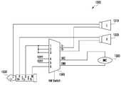
도 5를 참조하면, 전자장치 500는 프로세서(processor) 510, 메모리 520, 표시부 530, 커넥터 연결부 540, 커넥터 판단 모듈 545 및 스위치 모듈 550을 포함할 수 있다. 그리고 전자장치 500는 외부 출력 장치(예, 이어폰, 헤드셋) 501와 커넥터 연결부 540를 통해 연결될 수 있다.5, the
도시되지는 않았지만, 전술된 각각의 구성 요소들은 버스(bus)에 의해 서로 연결되어 있으며, 프로세서 510는 상기 구성 요소들(예, 메모리 520, 표시부 530, 커넥터 연결부 540, 스위치 모듈 550)에게 신호(예, 제어 메시지)를 전달하여 상기 구성 요소들을 제어할 수 있다.Although not shown, each of the above-described components is interconnected by a bus, and the
프로세서 510는 통상적으로 전자장치 500의 전반적인 동작을 제어할 수 있다. 예컨대, 프로세서 510는 상기 버스를 통해 전술한 다른 구성요소들(예, 메모리 520, 표시부 530, 커넥터 연결부 540, 스위치 모듈 550)로부터 응답을 수신하여, 수신된 응답을 해독하고, 해독된 응답에 따른 연산이나 데이터 처리를 실행할 수 있다. 도시되지는 않았지만, 프로세서 510는 AP(Application processor)와 코덱(codec)을 포함할 수 있으며, AP는 코텍을 기반으로 데이터 처리를 수행할 수 있다.The
프로세서 510는 제어 신호 모듈 511, 임피던스 측정 모듈 512, 오디오 증폭 모듈 513, 오디오 생성 모듈 514, 오디오 입력 모듈 515 및 커넥터 감지 모듈 516을 포함할 수 있다. 제어 신호 모듈 511은 다른 모듈들과의 신호를 제어할 수 있다. 예를 들어, 커넥터 감지 모듈 516을 통해 커넥터가 삽입되었음을 확인할 경우 제어 신호 모듈 511은 삽입된 커넥터의 구성을 확인하기 위해 임피던스 측정 모듈 512을 제어할 수 있다. 그리고 제어 신호 모듈 511은 확인된 커넥터의 구성을 기반으로 스위치 모듈 550을 제어할 수 있다.The
임피던스 측정 모듈 512은 외부 출력 장치의 임피던스를 측정할 수 있다. 예를 들어, 외부 출력 장치가 이어폰인 경우 임피던스 측정 모듈 512은 왼쪽 이어폰에 대한 임피던스(L임피던스)와 오른쪽 이어폰에 대한 임피던스(R임피던스)를 측정할 수 있다. 즉, 임피던스 측정 모듈 512은 전자장치 500에 구성된 4극 단자 중에서 TIP 단자와 RING1 단자를 통해 전송되는 신호에 대한 임피던스 값을 측정할 수 있다. 언밸런스 4극 단자가 LRGM순서로 구성되므로, 임피던스 측정 모듈 512은 L과 R을 통해 전송되는 신호에 대한 임피던스 값을 측정한다. 여기서 측정된 임피던스 값은 외부 출력 장치가 커넥터 단자를 어떤 순서로 구성하느냐에 따라, 다르게 측정될 수 있다. 프로세서 510는 임피던스 측정 모듈 512을 통해 측정된 L임피던스 값과 R임피던스 값을 기반으로 외부 출력 장치의 커넥터 단자 구성을 확인할 수 있다. 임피던스 측정 모듈 512은 프로세서 510 내부에 실장된 것으로 도시되었으나, 이에 한정하지는 않는다. 예를 들어, 임피던스 측정 모듈 512은 커넥터 판단 모듈 545에 포함되어, 외부 출력 장치 501가 연결되는 경우 능동적으로 외부 출력 장치 501의 임피던스 값을 측정할 수도 있다.
오디오 증폭 모듈 513은 오디오 신호를 증폭시킬 수 있다. 구체적으로 오디오 증폭 모듈 513은 오디오 신호의 진폭을 증폭시킬 수 있다. 예를 들어, 오디오 증폭 모듈 513은 오디오 생성 모듈 514로부터 L신호와 R신호를 수신하고, 아날로그 파형인 상기 L신호와 R신호를 증폭시킬 수 있다. 그리고 오디오 증폭 모듈 513은 증폭된 L신호와 R신호를 외부 출력 장치로 전송할 수 있다.The
오디오 생성 모듈 514은 메모리 520로부터 전송된 디지털(digital) 음원을 아날로그(analog) 파형으로 변환할 수 있다. 그리고 오디오 생성 모듈 514은 아날로그 파형으로 변환된 오디오 신호를 위상 반전시켜 차동 신호(differential signal)로 분리할 수 있다. 즉, 오디오 생성 모듈 514은 상기 오디오 신호를 L신호와 R신호로 분리할 수 있다.The
오디오 입력 모듈 515은 4극 커텍터의 단자들 중 SLEEVE 단자를 통해 외부 출력 장치로부터 입력되는 오디오(음성) 신호를 수신할 수 있다. 언밸런스 타입의 4극 커넥터는 표준을 따라 LRGM으로 구성될 수 있으며, SLEEVE 단자에는 M(Microphone) 신호가 연결될 수 있다. 즉, 오디오 입력 모듈 515은 외부 출력 장치(이어폰, 헤드셋)의 마이크로부터 수신된 오디오(음성) 신호를 상기 4극 커넥터의 SLEEVE 단자를 통해 수신할 수 있다.The
커넥터 감지 모듈 516은 커넥터 연결부 540에 연결되는 외부 출력 장치 501의 연결 여부를 감지할 수 있다. 예를 들어, 커넥터 감지 모듈 516은 외부 출력 장치 501가 연결된 경우 전압의 변화를 측정하여 외부 출력 장치 501의 커넥터 560에 대한 연결 여부를 감지할 수 있다. 또한, 커넥터 감지 모듈 516은 상기 전압의 변화를 기반으로 연결된 외부 출력 장치 501의 커넥터 560이 언밸런스 타입인지, 밸런스 타입인지 여부를 확인할 수도 있다. 그리고 커넥터 감지 모듈 516은 연결된 커넥터 560이 밸런스 타입인 경우, 커넥터의 단자 구성이 어떤 순서로 구성되어 있는지 여부도 확인할 수 있다. 커넥터 감지 모듈 516은 프로세서 510에 내장된 것으로 도시되었으나, 이에 한정하지는 않는다. 커넥터 감지 모듈 516은 커넥터 판단 모듈 545에 포함될 수 있으며, 외부 출력 장치 501가 연결되는 경우 즉각적으로 연결 여부를 판단하고, 상기 정보를 커넥터 판단 모듈 545에게 전달할 수도 있다.The
그리고 메모리 520는 멀티미디어 파일(예, 음악 파일, 이미지 파일)을 저장할 수 있다. 여기서 멀티미디어 파일은 음원(sound source)을 포함하고 있는 동영상 파일, 음악 파일 등을 포함할 수 있다. 메모리 장치는 외장 메모리와 내장 메모리를 모두 포함하며, 음원을 포함한 멀티미디어 파일을 저장할 수 있는 모든 저장 장치를 의미할 수 있다. 내장 메모리(예, ROM, NAND, RAM)는 네트워크를 통해 스트리밍 파일 및 다운로드 파일을 임시 또는 영구적으로 저장할 수 있는 메모리 장치일 수 있다. 예를 들어, 내장 메모리는 휘발성 메모리(volatile Memory)(예, DRAM(dynamic RAM), SRAM(static RAM), SDRAM(synchronous dynamic RAM)) 또는 비휘발성 메모리(non-volatile Memory)(예, OTPROM(one time programmable ROM), PROM(programmable ROM), EPROM(erasable and programmable ROM), EEPROM(electrically erasable and programmable ROM), mask ROM, flash ROM, NAND flash memory, NOR flash memory) 중 적어도 하나를 포함할 수 있다. 그리고 외장 메모리는 전자장치에 삽입하는 형식의 메모리 장치(예, T-Flash, MMC, SD Card)일 수 있다. 예를 들어, 외장 메모리는 flash drive, CF(compact flash), SD(secure digital), Micro-SD(micro secure digital), Mini-SD(mini secure digital), xD(extreme digital) 또는 Memory Stick 등을 포함할 수 있다. 상기 외장 메모리는 다양한 인터페이스를 통해 전자장치 500와 기능적으로 연결될 수 있다.The
표시부 530는 패널, 홀로그램 장치 또는 프로젝터를 포함할 수 있다. 상기 패널은, 예를 들면, LCD(liquid-crystal display) 또는 AM-OLED(active-matrix organic light-emitting diode) 등일 수 있다. 패널은 유연하게(flexible), 투명하게(transparent) 또는 착용할 수 있게(wearable) 구현될 수 있으며, 터치 패널과 하나의 모듈로 구성될 수도 있다. 즉, 표시부 530는 동영상이나 이미지 등을 표시할 수 있으며, 사용자의 터치 입력을 인식할 수도 있다. 예를 들어, 터치 패널은 정전식, 감압식, 적외선 방식 또는 초음파 방식 중 적어도 하나의 방식으로 터치 입력을 인식할 수 있다. 다양한 실시예에 따른 표시부 530는 외부 출력 장치의 왼쪽 출력부와 오른쪽 출력부를 확인하기 위한 사용자 입력을 수신할 수 있다. 예를 들어, 전자장치 500는 왼쪽 출력부와 오른쪽 출력부 중 하나의 출력부로 신호음을 출력하고, 사용자로부터 상기 신호음이 들린 출력부를 선택하도록 할 수 있다. 전자장치 500는 표시부 530를 통해 왼쪽 출력부와 오른쪽 출력부 중 하나를 선택할 수 있는 팝업(pop-up) 메시지를 표시하고, 상기 팝업 메시지에 대한 사용자 입력을 상기 표시부 530를 통해 수신할 수 있다.
커넥터 연결부 540는 전자장치 500와 외부 출력 장치(이어폰, 헤드셋) 501를 연결하기 위한 구성부일 수 있다. 전자장치 500는 외부 출력 장치 501의 커넥터 506이 연결될 수 있도록 커넥터 연결부 540를 구성할 수 있다. 커넥터 연결부 540는 외부 출력 장치 501의 커넥터 506인 언밸런스 타입 4극 커넥터 표준에 대응하여 LRGM신호를 전송할 수 있도록 구성할 수 있다. 다양한 실시예에 따른 커넥터 연결부 540는 언밸런스 타입 커넥터와 함께 밸런스 타입 커넥터도 지원할 수 있도록 회로가 구성될 수 있다.The
커넥터 판단 모듈 545은 전자장치 500에 연결된 외부 출력 장치 501의 커넥터 560에 대해 판단하기 위한 구성부일 수 있다. 예를 들어, 외부 출력 장치 501의 커넥터 560를 프로세서 510가 직접 판단할 수도 있겠으나, 커넥터 판단 모듈 545이 먼저 판단하고, 상기 외부 출력 장치 501의 커넥터 560에 대한 정보를 프로세서 510에게 전달하는 구조도 가능할 수 있다. 커넥터 판단 모듈 545은 임피던스 측정 모듈 512과 커넥터 감지 모듈 516의 기능을 수행할 수 있으며, 도시되지는 않았지만, 임피던스 측정 모듈 512과 커넥터 감지 모듈 516은 커넥터 판단 모듈 545에 포함될 수 있다.The
커넥터 판단 모듈 545은 외부 출력 장치 501가 전자장치 500에 연결되는 경우 외부 출력 장치 501의 연결 여부를 판단할 수 있다. 그리고 커넥터 판단 모듈 545은 상기 외부 출력 장치 501의 커넥터 560로 전기 신호를 전송하여, 커넥터 560의 유형(예, 밸런스 타입, 언밸런스 타입)을 판단할 수 있다. 또한, 커넥터 판단 모듈 545은 커넥터 560가 3극인지, 4극인지도 판단할 수 있고, 상기 전송한 전기 신호를 기반으로 상기 커넥터 560에 대한 임피던스 값을 확인하고, 상기 커넥터의 구성을 확인할 수도 있다. 커넥터 판단 모듈 545은 프로세서 510와 분리된 장소에 실장되어 외부 출력 장치 501에 대한 정보를 프로세서 510에게 전달해주는 역할을 수행할 수 있다. 다양한 실시예에 따른 전자장치 500의 프로세서 510는 커넥터 판단 모듈 545로부터 외부 출력 장치 501에 대한 정보를 수신하고, 상기 정보를 기반으로 스위치 모듈 550을 제어할 수도 있다.The
스위치 모듈 550은 전자장치 500의 회로에 포함된 스위치를 포함할 수 있다. 스위치 모듈 550은 커넥터 연결부 540와 프로세서 510 간의 위치한 스위치를 포함하며, 제어 신호 모듈 511의 제어 하에, 동작할 수 있다. 예를 들어, 전자장치 500는 외부 출력 장치 501의 연결 시, 커넥터 감지 모듈 516을 통해 측정된 전압 값과 임피던스 측정 모듈 512을 통해 측정된 임피던스 값을 기반으로 상기 스위치 모듈 550을 제어할 수 있다. 스위치 모듈 550은 외부 출력 장치 501가 언밸런스 타입이라고 가정하여 연결되어 있는 회로를 밸런스 타입에 대응되도록 스위치를 동작할 수 있다.The
다양한 실시예에 따른 전자장치 500는 외부 출력 장치 501와 연결되고, 상기 외부 출력 장치 501를 통해 오디오 신호를 출력할 수 있다.The
외부 출력 장치 501는 전자장치 500로부터 오디오 신호를 수신 받아 상기 오디오 신호를 출력부 570를 통해 출력할 수 있다. 예를 들어, 외부 출력 장치 501가 이어폰인 경우 전자장치 500는 커넥터 연결부 540를 통해 이어폰의 커넥터와 연결할 수 있다. 그리고 전자장치 500는 이어폰으로 오디오 신호를 전송하여 이어폰의 왼쪽 출력부(Left output)와 오른쪽 출력부(Right output)로 상기 오디오 신호가 출력되도록 할 수 있다. 전술된 내용에서 외부 출력 장치 501를 이어폰으로 설명하였으나, 이에 한정하지는 않는다.The
외부 출력 장치 501는 커넥터 560과 출력부 570를 포함할 수 있다. 커넥터 560은 전자장치 500로부터 오디오 신호를 수신하기 위한 전자장치 500와의 연결 수단일 수 있다. 커넥터 560은 balanced 커넥터 561과 unbalanced 커넥터 562으로 구분될 수 있으며, 일반적으로 외부 출력 장치 501는 unbalanced 커넥터 562을 포함할 수 있다. Banlanced 커넥터를 포함하는 외부 출력 장치 501는 밸런스 타입의 외부 출력 장치로, 언밸런스 타입과 비교하여 보다 고성능으로 오디오 신호를 출력할 수 있다. 그리고 출력부 570는 오디오 신호를 출력할 수 있으며, 왼쪽 출력부(Left output) 571와 오른쪽 출력부(Right output) 573로 구분될 수 있다.The
다양한 실시예에 따른 전자장치 500는 커넥터 연결부 540에 연결된 외부 출력 장치 501를 감지하고, 상기 외부 출력 장치 501의 커넥터 560 구성을 확인할 수 있다. 다양한 실시예에 따른 전자장치 500는 상기 확인된 커넥터 560 구성을 기반으로 스위치 모듈 550을 제어할 수 있다. 전자장치 500는 외부 출력 장치 501의 커넥터 560에 대응되는 회로를 사용하여 상기 외부 출력 장치 501를 지원할 수 있다.The
도 6a는 본 발명의 다양한 실시예에 따른 연결된 외부 출력 장치 커넥터의 구성을 확인한 후 상기 커넥터의 구성에 대응하여 결정된 회로를 통해 오디오를 출력하는 방법을 설명하기 위한 순서도이다.6A is a flowchart illustrating a method of outputting audio through a circuit determined in accordance with the configuration of the connector after confirming the configuration of a connected external output device connector according to various embodiments of the present invention.
도 6을 참조하면, 동작 601에서 전자장치 500는 외부 출력 장치 501의 연결을 감지할 수 있다. 예를 들어, 전자장치 500에 외부 출력 장치 501가 연결되는 경우 전자장치 500의 프로세서 510는 커넥터 감지 모듈 516을 통해 상기 외부 출력 장치 501의 연결을 감지할 수 있다. 외부 출력 장치 501의 커넥터 560이 전자장치 500의 커넥터 연결부 540에 연결되면, 전자장치 500의 프로세서 510는 커넥터 560의 연결을 감지할 수 있다.Referring to FIG. 6, in
그리고 동작 603에서 전자장치 500의 프로세서 510는 연결된 외부 출력 장치 501에 대한 전압 및 임피던스를 측정할 수 있다. 예를 들어, 프로세서 510는 커넥터 감지 모듈 516을 통해 외부 출력 장치 501에 대한 전압을 감지하고, 임피던스 측정 모듈 512을 통해 외부 출력 장치 501에 대한 임피던스를 측정할 수 있다. 전술된 내용은 커넥터 감지 모듈 516이 외부 출력 장치 501의 전압을 측정하고, 임피던스 측정 모듈 512이 임피던스를 측정하는 것으로 기재되었으나, 이에 한정하지는 않는다. 프로세서 510는 커넥터 감지 모듈 516을 통해 커넥터 560의 SLEEVE 단자에 대응되는 회로로 외부 출력 장치 501의 전압을 측정할 수 있다. 그리고 프로세서 510는 임피던스 측정 모듈 512을 통해 외부 출력 장치 501의 출력부(Left output, Right output)에 대한 임피던스를 측정할 수 있다. 기본적으로 전자장치 500의 커넥터 연결부 540는 언밸런스 타입의 커넥터를 지원하도록 TIP 단자가 L신호에 연결되고, RING1 단자가 R신호에 연결될 수 있다. 이에 따라, 임피던스 측정 모듈 512은 TIP단자를 통해 LEFT OUTPUT 571에 대한 임피던스를 측정하고, RING1 단자를 통해 RIGHT OUTPUT 572에 대한 임피던스를 측정할 수 있다.And in
그리고 동작 605에서 프로세서 510는 상기 측정된 전압 및 임피던스를 기반으로 상기 외부 출력 장치 501에 대한 커넥터 560의 구성을 확인할 수 있다. 예를 들어, 프로세서 510는 외부 출력 장치 501가 언밸런스 타입인지, 밸런스 타입인지를 확인할 수 있다. 다양한 실시예에 따른 프로세서 510는 밸런스 타입인 경우 외부 출력 장치 501의 커넥터 560에 대한 단자 구성까지도 확인할 수 있다. 전자장치 500는 연결된 커넥터에 대한 단자 구성을 확인할 필요가 있을 수 있다. 다양한 실시예에 따른 프로세서 510는 측정된 전압 및 임피던스를 기반으로 외부 출력 장치 501에 대한 커넥터 560의 단자 구성까지 확인할 수 있다. 동작 605에 대한 보다 구체적인 설명은 도 6b의 상세한 설명에서 추가 설명한다.In
동작 607에서 프로세서 510는 확인된 커넥터 560의 구성에 대응하여 회로를 결정할 수 있다. 예를 들어, 프로세서 510는 커넥터 560의 구성에 대응하여 스위치 모듈 550을 제어할 수 있다. 프로세서 510는 스위치 모듈 550을 제어하여 회로 구성을 변경할 수 있으며, 언밸런스 타입의 외부 출력 장치뿐만 아니라, 밸런스 타입의 외부 출력 장치까지 지원할 수 있다.At
동작 609에서 프로세서 510는 상기 결정된 회로를 통해 오디오 신호를 출력할 수 있다. 예를 들어, 프로세서 510는 외부 출력 장치 501가 밸런스 타입인 경우 출력부 570의 LEFT OUTPUT 571과 RIGHT OUTPUT 573을 구별하여 오디오 신호를 출력할 수 있다. 프로세서 510는 오디오 생성 모듈 514을 통해 메모리 520에 저장된 동영상, 오디오 파일로부터 오디오를 생성할 수 있다. 그리고 프로세서 510는 오디오 증폭 모듈 513을 이용하여 상기 생성된 오디오를 증폭시키고, 상기 결정된 회로를 통해 상기 오디오를 외부 출력 장치 501의 출력부 570에서 출력할 수 있다.In
도 6b는 본 발명의 다양한 실시예에 따른 연결된 외부 출력 장치의 유형과 외부 출력 장치의 커넥터 구성을 확인하는 방법을 구체적으로 도식화한 순서도이다.6B is a flowchart illustrating a method of confirming the type of the connected external output device and the connector configuration of the external output device according to various embodiments of the present invention.
도 6b를 참조하면, 동작 611에서 전자장치 500의 프로세서 510는 연결된 외부 출력 장치에 대한 전압 및 임피던스를 측정할 수 있다. 동작 611은 전술된 도 6a에서의 동작 603과 동일한 과정일 수 있다. 따라서, 동작 611에 대한 구체적인 설명은 도 6a 동작 603에 대한 상세한 설명으로 대체할 수 있다.Referring to FIG. 6B, in
도 6b의 동작 613 내지 동작 617은 도 6a의 동작 605에 대응되는 동작이며, 도 6b는 도 6a의 동작 605에 대해 보다 구체적으로 설명하기 위해 도식한 흐름도이다. 동작 613에서 프로세서 510는 상기 측정된 전압 및 임피던스를 기반으로 상기 외부 출력 장치의 유형을 확인할 수 있다. 예를 들어, 프로세서 510는 상기 측정된 전압 및 임피던스를 토대로, 외부 출력 장치 501가 언밸런스 타입인지, 밸런스 타입인지를 판단할 수 있다. 또한, 프로세서 510는 상기 외부 출력 장치 501가 3극 커넥터로 구성되었는지, 4극 커넥터로 구성되었는지를 판단할 수도 있다. 동작 615에서 프로세서 510는 외부 출력 장치 501가 밸런스 타입인지 여부를 판단할 수 있다. 만약 외부 출력 장치 501가 밸런스 타입인 경우 동작 617에서 프로세서 510는 외부 출력 장치의 커넥터 구성을 확인할 수 있다. 예를 들어, 밸런스 타입의 커넥터 구성은 외부 출력 장치 501마다 다르게 구성될 수 있으며, 이에 따라, 프로세서 510는 상기 커넥터 구성을 확인할 수 있다. 구체적으로, 커넥터 구성은 4극 커넥터 기준으로, TIP 단자, RING1 단자, RING2 단자, SLEEVE 단자에 대응되는 구성이 외부 출력 장치 501마다 다를 수 있다. 따라서, 동작 617에서 프로세서 510는 상기 측정된 전압 및 임피던스를 기반으로 상기 외부 출력 장치 501의 커넥터 구성을 확인할 수 있다. 다양한 실시예에 따라, 동작 617에서 프로세서 510는 커넥터 구성을 확인하기 위해 추가로 임피던스를 측정할 수 있다. 그리고 동작 619에서 프로세서 510는 상기 확인된 커넥터 구성에 대응되는 회로를 선택할 수 있다. 동작 619는 전술된 도 6a에서의 동작 607과 동일한 과정일 수 있다. 따라서, 동작 619에 대한 구체적인 설명은 도 6a 동작 603에 대한 상세한 설명으로 대체할 수 있다.6B is an operation corresponding to
도 7은 본 발명의 다양한 실시예에 따른 연결된 외부 출력 장치가 밸런스 타입이냐, 언밴런스 타입이냐에 따라 다른 회로가 결정되는 방법을 설명하기 위한 순서도이다.FIG. 7 is a flowchart illustrating a method of determining a different circuit depending on whether a connected external output device according to various embodiments of the present invention is a balance type or an unvary type.
도 7을 참조하면, 동작 701 내지 동작 705에 대한 설명은 전술된 도 6의 동작 601 내지 동작 605에 대한 설명과 동일하다. 그리고 동작 707에서 전자장치 500의 프로세서 510는 외부 출력 장치 501가 언밸런스 타입인지, 밸런스 타입인지 여부를 확인할 수 있다. 다양한 실시예에 따르면, 프로세서 510는 동작 703에서 측정한 임피던스 값을 기반으로 외부 출력 장치 501의 타입을 구별할 수 있다. 구체적으로 프로세서 510는 외부 출력 장치 501의 LEFT OUTPUT에 대한 임피던스 값(L-Imp)과 RIGHT OUTPUT 에 대한 임피던스 값(R-Imp)을 기반으로 상기 외부 출력 장치 501의 타입을 구별할 수 있다. 다양한 실시예에 따라 임피던스 값을 통해 외부 출력 장치 501의 커넥터 560에 대한 단자 구성도 구별할 수 있다. 다른 실시예에 따르면, 프로세서 510는 동작 703에서 측정한 전압 값을 기반으로 외부 출력 장치 501의 타입을 구별할 수 있다. 또 다른 실시예에 따르면, 프로세서 510는 상기 측정한 전압 값을 기반으로 외부 출력 장치 501의 커넥터 560가 3극인지, 4극인지를 판단하고, 외부 출력 장치 501의 타입(예, balanced/unbalanced)도 함께 판단할 수 있다.Referring to FIG. 7, descriptions of
동작 707에서 외부 출력 장치 501가 언밸런스 타입인 경우 동작 709에서 프로세서 510는 언밸런스 타입에 대응되는 회로를 결정할 수 있다. 예를 들어, 프로세서 510는 스위치 모듈 550을 제어하여 언밸런스 타입에 대응되는 회로를 결정할 수 있다. 전자장치 500는 기본적으로 언밸런스 타입을 지원하도록 회로가 구성되어 있으므로, 외부 출력 장치 501가 언밸런스 타입인 경우 프로세서 510는 기 설정된 회로 상태로 외부 출력 장치 501를 지원할 수 있다.If
동작 709에서 언밸런스 타입에 대응되는 회로를 결정한 후 동작 713에서 프로세서 510는 상기 결정된 회로를 통해 오디오 신호를 출력할 수 있다. 즉, 프로세서 510는 상기 오디오 신호를 연결된 외부 출력 장치의 출력부를 통해 출력할 수 있다.After determining a circuit corresponding to the unbalanced type in
그리고 동작 707에서 외부 출력 장치 501가 밸런스 타입인 경우 동작 711에서 프로세서 510는 밸런스 타입에 대응되는 회로를 결정할 수 있다. 예를 들어, 프로세서 510는 스위치 모듈 550을 제어하여 밸런스 타입에 대응되는 회로를 결정할 수 있다. 여기서 결정된 회로는 여러 종류의 밸런스 타입을 기반으로 미리 설정된 회로일 수 있다. 다양한 실시예에 따라 임피던스 값을 통해 외부 출력 장치 501의 커넥터 560에 대한 단자 구성도 구별할 수 있다.If the
도 8a와 8b는 본 발명의 다양한 실시예에 따른 언밸런스 타입의 커넥터와의 호환성을 고려한 밸런스 타입의 커넥터 구성에 대한 예시도이다.8A and 8B are diagrams for illustrating a balance type connector configuration considering compatibility with an unbalanced type connector according to various embodiments of the present invention.
도 8a를 참조하면, 밸런스 타입의 커넥터 220(4극)에 대한 예시를 도시하고 있다. 밸런스 타입의 커넥터 220은 오디오 신호에 대해 + 신호와 ? 신호가 있을 수 있다. 그리고 외부 출력 장치 501는 왼쪽 출력부와 오른쪽 출력부로 구분하여, 오디오 신호를 각각 출력할 수 있다. 다양한 실시예에 따라 밸런스 타입의 커넥터 220은 L+, L-, R+, R- 신호로 구성될 수 있다. 언밸런스 타입의 커넥터 210은 LRGM의 순서로 4극 단자가 구성될 수 있다. 언밸런스 타입을 지원하는 전자장치가 밸런스 타입의 커넥터 220을 보다 용이하게 지원하기 위해서, 밸런스 타입의 커넥터 220은 L+, R+, L-, R- 순서로 구성될 수 있다. 즉, 도 8a의 밸런스 타입 커넥터 220은 TIP 단자 211에 L+, RING1 단자 213에 R+, RING2 단자 215에 L-, SLEEVE 단자 217에 R- 로 구성될 수 있다. 도 8a의 밸런스 타입 커넥터 220은 언밸런스 타입 커넥터 210과 비교하여, RING2 단자 215와 SLEEVE 단자 217만 바뀐 구성일 수 있다.Referring to Fig. 8A, an example of a balanced type connector 220 (four poles) is shown. The
도 8b를 참조하면, 단자가 다르게 구성된 밸런스 타입의 커넥터 220(4극)을 도시하고 있다. 도 8b의 밸런스 타입 커넥터 220은 도 8a와 비교하여, RING2 단자 215는 R- 로, SLEEVE 단자 217는 L-로 구성될 수 있다. 도 8b의 밸런스 타입 커넥터 220도 언밸런스 타입 커넥터 210과 비교하여, RING2 단자 215와 SLEEVE 단자 217만 바뀐 구성일 수 있다.Referring to FIG. 8B, a balanced type connector 220 (four poles) having different terminals is shown. 8B, the
전자장치 500의 프로세서 510는 도 8a와 8b의 밸런스 타입 커넥터 220(예, 호환성을 고려한 밸런스 타입 커넥터)으로 구성된 외부 출력 장치 501가 연결될 경우, 스위치 모듈 540을 이용한 회로 변경를 통해 상기 외부 출력 장치 501를 지원할 수 있다.The
도 9는 본 발명의 다양한 실시예에 따른 밸런스 타입의 출력 장치가 전자장치에 연결된 경우 전자장치의 동작에 대한 예시도이다.9 is an exemplary diagram of the operation of an electronic device when a balanced type output device according to various embodiments of the present invention is connected to the electronic device.
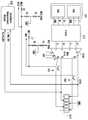
도 9를 참조하면, 전자장치 500는 밸런스 타입의 이어폰(출력 장치)이 커넥터 연결부 540를 통해 연결된 상태일 수 있다. 밸런스 타입의 이어폰은 왼쪽 출력부 250와 오른쪽 출력부 260로 구분되어 있으며, 4극 밸런스 타입 커넥터 220을 이용하여 전자장치 500에 연결된 상태일 수 있다. 전자장치 500의 프로세서 510는 밸런스 타입 커넥터 220이 연결되면, 커넥터 감지 모듈 516을 통해 상기 밸런스 타입 커넥터 220의 연결을 확인할 수 있다. 다양한 실시예에 따라, 커넥터 감지 모듈 516은 이어폰 삽입 시의 전압의 변화를 확인할 수 있다. 그리고 프로세서 510는 임피던스 측정 모듈 512을 통해 상기 밸런스 타입 커넥터 220의 단자 구성을 확인할 수 있다. 프로세서 510는 상기 전압의 변화 값과 상기 임피던스 값을 내부 버퍼 또는 램에 저장하고, 상기 저장된 값을 기반으로 상기 밸런스 타입 커넥터 220의 단자 구성을 확인할 수 있다. 임피던스 측정 모듈 512이 측정하는 임피던스에 관한 설명은 도 10에서 후술한다. 프로세서 510는 상기 밸런스 타입 커넥터 220의 단자 구성을 확인한 후, 제어 신호 모듈 511을 통해 스위치 모듈 550을 제어할 수 있다. 프로세서 510는 상기 밸런스 타입 커넥터 220의 단자 구성에 대응되도록 회로를 변경할 수 있다. 그리고 프로세서 510는 오디오 생성 모듈 514과 오디오 증폭 모듈 513을 이용하여 변경된 회로를 통해 오디오 신호를 밸런스 타입의 이어폰에게 전송할 수 있다. 즉, 전자장치 500의 프로세서 510는 언밸런스 타입의 출력 장치 외에, 호환성을 고려한 밸런스 타입의 출력 장치를 지원할 수 있다.Referring to FIG. 9, the
도 10은 본 발명의 다양한 실시예에 따른 밸런스 타입의 출력 장치가 전자장치에 연결된 경우 출력 장치에 대한 임피던스 및 전압을 측정하기 위한 전자장치의 동작에 대한 예시도이다.10 is an illustration of the operation of an electronic device for measuring impedance and voltage to an output device when a balanced type output device according to various embodiments of the present invention is connected to the electronic device.
도 10을 참조하면, 전자장치 500의 프로세서 510는 커넥터 감지 모듈 516을 통해 밸런스 타입 이어폰의 연결을 확인할 수 있다. 그리고 프로세서 510는 상기 밸런스 타입 이어폰의 단자 구성을 확인하기 위해 상기 밸런스 타입 이어폰의 임피던스 및 전압을 측정할 수 있다. 예를 들어, 밸런스 타입 이어폰의 왼쪽 출력부 250에 대한 임피던스 측정만을 설명하나, 이에 한정하지는 않는다.Referring to FIG. 10, the
프로세서 510는 밸런스 타입 이어폰에 대한 임피던스를 측정 하기 위해 임피던스 측정 모듈 512을 제어하여 상기 밸런스 타입 이어폰으로 미세한 전류를 공급할 수 있다. 미세한 전류는 밸런스 타입 커넥터 220을 통해 이어폰의 왼쪽 출력부 250로 공급될 수 있다. 그리고 미세한 전류는 스위치 모듈 550을 통해 기 설정된 회로를 통해 회귀한다. 여기서 프로세서 510는 스위치 모듈 550을 제어하여 미리 임피던스 측정을 위한 회로로 설정할 수 있다. 프로세서 510는 전술된 과정을 통해 이어폰의 왼쪽 출력부 250에 대한 임피던스 값(L-Impedence)을 측정할 수 있다. 그리고 프로세서 510는 커넥터 감지 모듈 516을 통해 상기 밸런스 타입 이어폰의 연결에 따른 전압 변화를 측정할 수 있다. 아래 표 1은 전자장치 500에 연결된 외부 출력 장치의 커넥터 구성에 따라, 다르게 측정되는 임피던스 값과 전압에 대한 예시 값을 포함한다.The

위의 표 1을 참조하면, 전자장치 500에 연결되는 외부 출력 장치가 일반 3극 커넥터(언밸런스 타입 3극 커넥터)으로 구성된 경우 L-Imp(왼쪽 출력부 임피던스)와 R-Imp(오른쪽 출력부 임피던스)는 수Ω에서 수백Ω으로 측정될 수 있다. 그리고 상기 일반 3극 커넥터에서 측정되는 전압은 0 V 일 수 있다.Referring to Table 1 above, when the external output device connected to the
그리고 전자장치 500에 연결되는 외부 출력 장치가 밸런스 타입 4극 커넥터(L+, R+, L-, R-)으로 구성된 경우 L-Imp(왼쪽 출력부 임피던스)는 수Ω에서 수백Ω으로 측정되고, R-Imp(오른쪽 출력부 임피던스)는 Open된 상태로 측정될 수 있다. 여기서 임피던스가 Open으로 측정되는 것은 공급된 전류가 마이크를 통해 흘러나갔다는 의미일 수 있다. 그리고 상기 밸런스 타입 4극 커넥터(L+, R+, L-, R-)에서 측정되는 전압은 2.7 V 일 수 있다.And the external output device connected to the
또한, 전자장치 500에 연결되는 외부 출력 장치가 밸런스 타입 4극 커넥터(L+, L-, R+, R-)으로 구성된 경우 L-Imp(왼쪽 출력부 임피던스)와 R-Imp(오른쪽 출력부 임피던스)는 둘 다 Open으로 측정될 수 있다. 그리고 상기 밸런스 타입 4극 커넥터(L+, L-, R+, R-)에서 측정되는 전압은 0.05 V에서 0.3 V일 수 있다.The L-Imp (left output side impedance) and R-Imp (right output side impedance) when the external output device connected to the
전술된 내용과 같이, 전자장치 500의 프로세서 510는 외부 출력 장치에 대한 왼쪽 출력부와 오른쪽 출력부에 대한 임피던스 측정 값과 전압 값을 기반으로 외부 출력 장치 커넥터의 구성을 확인할 수 있다. 전술된 표 1에 기재된 측정 값은 미리 실험을 통해 측정된 값이며, 이에 한정되지는 않는다. 예를 들어, 전술된 표 1은 수Ω에서 수백Ω으로 임피던스 값을 예시하였으나, 유선 오디오 출력 장치의 종류에 따라 임피던스 값은 다르게 측정될 수 있다. 특히, 제조사에 따라 제공되는 이어폰에 대한 임피던스 값은 다를 수 있다. 아래 표 2는 각 제조사 별로 측정되는 임피던스 값의 예시이다.As described above, the

제조사 별로, 혹은 출력 장치의 종류 별로 측정되는 임피던스 값은 차이가 있을 수 있으나, 프로세서 510는 출력 장치에 대한 임피던스 값과 전압 값을 기반으로 출력 장치의 커넥터 구성을 확인할 수 있다.The impedance values measured by the manufacturer or the output device may differ, but the
다양한 실시예에 따르면, 표 1에 개시된 밸런스 타입 4극 커넥터(L+, L-, R+, R-)과 밸런스 타입 4극 커넥터(R+, R-, L+, L-)은 왼쪽 출력부와 오른쪽 출력부에 대한 구별이 어려울 수 있다. 이에 따라, 프로세서 510는 사용자에게 왼쪽, 오른쪽에 대한 판단을 요청할 수 있다. 예를 들어, 프로세서 510는 왼쪽 출력부 또는 오른쪽 출력부 중 하나의 출력부를 통해 특정 신호음을 출력하고, 표시부 530에 출력부 판단과 관련된 알림 창(pop up 메시지)을 표시할 수 있다. 그리고 프로세서 510는 사용자의 입력을 수신하여 왼쪽 출력부와 오른쪽 출력부에 대한 구별을 할 수 있다. 여기서 왼쪽 출력부와 오른쪽 출력부에 대한 판단을 위해 표시부 530에 알림 창을 표시한다고 설명하였으나, 이에 한정하지는 않는다. 예컨대, 출력 장치에 특정 센서를 장착하고, 상기 특정 센서를 활용하여 출력부에 대한 판단을 할 수도 있다.According to various embodiments, the balance type 4-pole connectors (L +, L-, R +, R-) and balance type 4-pole connectors (R +, R-, L +, L-) The distinction between wealth can be difficult. Accordingly, the
도 11은 본 발명의 다양한 실시예에 따른 여러 종류로 구성된 밸런스 타입의 출력 장치 구성에 대한 예시도이다.11 is a diagram illustrating an example of a configuration of a balanced output apparatus of various types according to various embodiments of the present invention.
도 11을 참조하면, 외부 출력 장치 커넥터는 여러 종류의 구성이 있을 수 있다. 다양한 실시예에 따라, 도 8a와 8b에서 설명했던 밸런스 타입 4극 커넥터 220(케이스 1, 케이스 2)은 TIP단자가 L+로, RING1 단자가 R+로 고정된 경우의 커넥터다. 즉, 도8a와 8b에서 설명했던 밸런스 타입 4극 커넥터 220(케이스 1, 케이스 2)은 언밸런스 타입의 커넥터와의 호환성을 고려한 커넥터 구성일 수 있다. 이외에, 밸런스 타입 4극 커넥터 220은 L+, L-, R+, R-(케이스 3) 순서로 구성될 수도 있고, R+, R-, L+, L-(케이스 4) 순서로 구성될 수도 있다. 또한, 밸런스 타입 4극 커넥터 220은 R+, L+, R-, L-(케이스 5) 순서로 구성될 수도 있고, R+, L+, L-, R-(케이스 6) 순서로 구성될 수도 있다. 여기서 구성된 순서는 TIP 단자 211, RING1 단자 213, RING2 단자 215, SLEEVE 단자 217 순서이다. 다양한 실시예에 따른 외부 출력 장치 커넥터는 6개의 예시를 개시하였으나, 이에 한정하지는 않는다.Referring to FIG. 11, the external output device connector may have various kinds of configurations. According to various embodiments, the balanced type four-pole connector 220 (
도 12는 본 발명의 다양한 실시예에 따른 여러 종류로 구성된 밸런스 타입의 출력 장치 커넥터가 전자장치에 연결된 경우 전자장치의 동작에 대한 예시도이다.Figure 12 is an exemplary view of the operation of an electronic device when multiple types of balanced output device connectors are connected to the electronic device in accordance with various embodiments of the present invention.
도 12를 참조하면, 전자장치 500는 밸런스 타입의 이어폰(출력 장치)이 커넥터 연결부 540를 통해 연결된 상태일 수 있다. 여기서 밸런스 타입의 커넥터는 L+, L-, R+, R- 순서로 구성된 상태일 수 있다. 전자장치 500의 프로세서 510는 임피던스 측정 모듈 512을 통해 상기 밸런스 타입의 이어폰에 대한 임피던스 값을 측정할 수 있다. 예를 들어, 프로세서 510는 왼쪽 출력부에 대한 임피던스 값(L-Impedence)을 측정할 수 있다. 프로세서 510는 L-Imp 공급 단자 1220를 통해 전류를 공급할 수 있다. 밸런스 타입의 커넥터는 L+, L-, R+, R- 순서로 구성되어 있으므로, 프로세서 510가 L-Imp 공급 단자 1220를 통해 공급한 전류는 TIP 단자 211 통해 들어와서 RING1 단자 213로 나갈 수 있다. 여기서 RING1 단자 213는 임피던스 측정 모듈 512의 R-Imp 공급 단자 1230와 연결된 상태일 수 있다. 즉, 왼쪽 출력부에 대한 임피던스 값(L-Impedence)은 Open으로 측정될 수 있고, 오른쪽 출력부에 대한 임피던스 값(R-Impedence)도 동일하게 Open으로 측정될 수 있다. 프로세서 510는 전술된 측정 값을 기반으로 TIP 단자 211와 RING1 단자 213가 동일한 출력부로 구성되었음을 확인할 수 있다.Referring to FIG. 12, the
그리고 전자장치 500의 프로세서 510는 제어 신호 모듈 511을 제어하여 스위치 모듈 550을 제어할 수 있다. 추가적으로 전자장치 500는 TIP 단자 211 를 통해 특정 출력부(예, 왼쪽 출력부, 오른쪽 출력부)의 오디오 신호를 송신하고, RING1 단자 213를 통해 상기 오디오 신호를 수신하기 위해 MUX 회로 1210를 추가할 수 있다. 여기서 MUX 회로 1210는 프로세서 510 내부 혹은 외부에 내장될 수 있다. 상기 MUX 회로 1210는 오디오 증폭 모듈 513과 스위치 모듈 550 사이를 연결할 수 있다. 프로세서 510는 임피던스 측정 모듈 512을 통해 측정된 임피던스 값을 기반으로, 제어 신호 모듈 511에 의해 MUX 회로 1210를 제어할 수 있다. 예를 들어, 프로세서 510는 미리 저장된 외부 출력 장치의 구성(예, 아래에 도시된 표 3 MUX 테이블)에 따라 MUX 회로 1210를 단계별로 제어할 수 있다.The

프로세서 510는 위의 표 3 MUX 테이블을 기반으로, 밸런스 타입 이이폰을 지원할 수 있다. 상기 MUX 테이블은 도 11에 도시된 케이스들에 대한 예시 값을 도시하였으며, 이에 한정하지는 않는다. 다양한 실시예에 따른 전자장치는 여러 종류로 구성된 밸런스 타입의 출력 장치 커넥터가 연결된 경우, 상기 출력 장치 커넥터의 구성을 확인하고, 상기 확인된 구성을 기반으로 회로를 변경할 수 있다. 즉, 전자장치는 회로를 변경하여 다양한 구성의 밸런스 타입 출력 장치를 지원할 수 있다.The
도 13은 본 발명의 다양한 실시예에 따른 4극 밸런스 타입의 출력 장치에 마이크가 포함되는 경우 출력 장치 구성에 대한 예시도이다.13 is an exemplary diagram illustrating an output device configuration when a microphone is included in a quadrupole balance type output device according to various embodiments of the present invention.
도 13을 참조하면, 마이크 1330를 포함하고 있는 외부 출력 장치 1300에 대한 회로 구성을 도시한다. 외부 출력 장치(예, 이어폰) 1300은 왼쪽 출력부 1310와 오른쪽 출력부 1320가 나뉘어 있으며, 커넥터 1350 및 마이크 1330를 포함한다. 외부 출력 장치 1300는 마이크 1330 기능을 활성화하기 전에는 밸런스 타입의 출력 장치로 사용되고, 마이크 1330 기능이 활성화될 경우에는 RING2 단자 215와 SLEEVE 단자 217가 그라운드(GND)와 마이크(MIC)에 연결되도록 할 수 있다. 여기서 마이크 1330 기능의 활성화는 외부 출력 장치 1300에 버튼을 추가하여, 상기 버튼에 대한 사용자 입력에 따라 마이크 1330 기능이 활성화될 수 있다. 전술된 과정을 수행하기 위해, 외부 출력 장치 1300는 내부에 MUX(HW Switch) 1340를 추가할 수 있다. 아래의 표 4는 밸런스 타입의 외부 출력 장치와 언밸런스 타입의 외부 출력 장치가 연결된 경우의 MUX 동작에 대한 예시이다. 그리고 마이크 1330 기능의 활성화 여부에 따른 MUX 동작에 대한 예시도 포함한다.Referring to FIG. 13, there is shown a circuit configuration for an

위의 표 4를 참조하면, 밸런스 타입의 외부 출력 장치 1300로 사용하고자 하는 경우 외부 출력 장치 1300는 밸런스 타입의 출력을 지원하기 위해 L-(예, RING2 단자)가 Port1에 연결되고, R-(예, SLEEVE 단자)가 Port6에 연결될 수 있다. 이 때, 외부 출력 장치 1300의 MIC는 Port 4에 연결되어 OPEN 상태가 되고, GND는 Port 5에 연결되어 OPEN상태가 될 수 있다. 그리고 외부 출력 장치 1300의 마이크가 활성화될 경우(예, 전화가 연결된 경우) 외부 출력 장치 1300는 언밸런스 타입으로 전환될 수 있다. 즉, 마이크 기능을 사용하기 위해 외부 출력 장치 1300는 MIC(예, SLEEVE 단자)가 Port 6에 연결되고, GND(예, RING2 단자)가 Port 3에 연결될 수 있다.Referring to Table 4 above, when it is desired to use the
추가적으로, 밸런스 타입의 외부 출력 장치 1300로 사용 도중에 마이크를 활성화시키는 방법에 대한 예시를 추가 설명한다. 밸런스 오디오 신호를 출력하는 상태에서 마이크를 사용하는 어플(예, 통화 관련 어플)이 동작될 경우 임피던스 값이나 전압 값을 다시 체크할 수 있다.Additionally, an example of a method of activating a microphone during use with a balanced
예컨대, 언밸런스 타입으로 인식되어 있는 외부 출력 장치 1300에서 언밸런스 타입을 밸런스 타입으로 변경하는 경우 전압 값은 변경될 수 있다. 전자장치는 변경된 전압 값에 따라 발생된 인터럽트를 확인하고, 외부 출력 장치 1300의 임피던스 값이나 전압 값을 재측정할 수 있다. 그리고 전자장치는 재측정된 임피던스 값이나 전압 값을 기반으로 밸런스 타입의 외부 출력 장치 1300를 지원하기 위해 회로를 변경할 수 있다. 외부 출력 장치 1300의 타입 변경(언밸런스 타입에서 밸런스 타입으로의 변경) 여부는 전압 값뿐만 아니라, 임피던스 값을 통해서도 확인할 수 있다.For example, when the unbalanced type is changed to the balanced type in the
다양한 실시예에 따르면, 밸런스 타입의 외부 출력 장치 1300가 언밸런스 타입으로 변경되는 경우에는 임피던스 값의 측정을 통해서 확인할 수 있다. 예를 들어, 상기 외부 출력 장치 1300가 연결되어 지속적으로 오디오 신호가 출력되고 있는 상태라면, 전자장치는 상기 외부 출력 장치 1300의 임피던스 값을 측정할 수 있다. 오디오 신호가 출력되고 있다는 것은 전류가 계속 흐르고 있다는 의미이므로, 상기 전류를 통해 임피던스를 측정할 수 있다. 만약, 외부 출력 장치 1300에서 어떠한 소리도 출력되지 않는 상태라면, 전자장치는 주기적으로 펄스파(청음 대역 밖의 주파수)를 발생시켜서 임피던스를 측정할 수 있다. 전술된 과정을 통해 전자장치는 외부 출력 장치 1300의 임피던스를 지속적으로 측정할 수 있다. 그리고 상기 임피던스 값이 변경될 경우 전자장치는 임피던스 값과 전압 값을 재측정하고, 재측정된 임피던스 값과 전압 값을 기반으로 밸런스 타입 출력을 언밸런스 타입 출력으로 변경할 수 있다.According to various embodiments, when the balanced
도 14a와 14b는 본 발명의 다양한 실시예에 따른 5극 커넥터가 전자장치에 연결된 경우 전자장치의 동작을 설명하기 위한 흐름도이다.14A and 14B are flow charts illustrating the operation of an electronic device when a five-pole connector according to various embodiments of the present invention is connected to the electronic device.
도 14a를 참조하면, 동작 1401에서 전자장치 500의 프로세서 510는 외부 출력 장치 501의 연결을 감지할 수 있다. 예를 들어, 프로세서 510는 커넥터 감지 모듈 516을 통해 상기 외부 출력 장치 501의 연결을 감지할 수 있다. 동작 1403에서 프로세서 510는 외부 출력 장치 501의 커넥터가 5극인지 여부를 확인할 수 있다. 5극 커넥터는 단자가 총 5개로 구성되어 있으며, 전자장치 500는 5극 커넥터를 지원하기 위해 다른 구성을 추가할 수도 있다. 동작 1403에서 외부 출력 장치 501의 커넥터가 5극이 아닌 경우 동작 1405에서 프로세서 510는 연결된 외부 출력 장치 501에 대한 전압 및 임피던스를 측정할 수 있다. 동작 1405 내지 동작 1415에 대한 과정은 도 7에서의 동작 703 내지 동작 711에 대한 과정과 동일할 수 있다. 동작 1405 내지 동작 1415에 대한 설명은 전술된 도 7에 대한 상세한 설명에서 설명하였으므로, 생략한다.Referring to FIG. 14A, in
그리고 동작 1403에서 외부 출력 장치 501의 커넥터가 5극인 경우 도 14b의 동작 A로 이동할 수 있다. 도 14b를 참조하면, 외부 출력 장치 501의 커넥터가 5극인 경우 동작 1417에서 프로세서 510는 삽입된 5극 커넥터 기반의 외부 출력 장치에 대한 전압 및 임피던스를 측정할 수 있다. 상기 전압 및 임피던스를 측정하는 과정은 4극 커넥터와 동일한 과정이므로, 이에 대한 설명은 생략한다. 그리고 동작 1419에서 프로세서 510는 상기 측정된 전압 및 임피던스를 기반으로 5극 커넥터의 구성을 확인할 수 있다. 동작 1421에서 프로세서 510는 상기 5극 커넥터가 언밸런스 타입인지, 밸런스 타입인지 여부를 확인할 수 있다. 동작 1421에서 상기 5극 커넥터가 언밸런스 타입인 경우 동작 1423에서 프로세서 510는 언밸런스 타입에 대응되는 회로를 결정할 수 있다. 반대로, 동작 1421에서 상기 5극 커넥터가 밸런스 타입인 경우 동작 1425에서 프로세서 510는 밸런스 타입에 대응되는 회로를 결정할 수 있다. 그리고 동작 1415에서 프로세서 510는 상기 결정된 회로를 통해 오디오 신호를 출력할 수 있다.In
본 발명의 다양한 실시예에 따른 전자장치는 5극 커넥터가 연결될 경우 기존 4극 단자를 밸런스 타입 오디오 출력을 위해 활용하고, 나머지 5번째 단자를 그라운드로 활용할 수 있다. 이로 인해, 전자장치는 4극 단자보다 더욱 효율적으로 오디오 신호를 전송할 수 있다.In the electronic device according to various embodiments of the present invention, when a five-pole connector is connected, existing four-pole terminals can be utilized for balanced-type audio output, and the remaining fifth terminal can be used as ground. As a result, the electronic device can transmit the audio signal more efficiently than the four-pole terminal.
도 15a와 15b는 본 발명의 다양한 실시예에 따른 5극 밸런스 타입의 커넥터 예시도와 상기 5극 밸런스 타입의 커넥터가 전자장치에 연결된 상태에 대한 예시도이다.FIGS. 15A and 15B illustrate examples of a 5-pole balanced type connector according to various embodiments of the present invention and a state in which the 5-pole balanced type connector is connected to an electronic device.
도 15a를 참조하면, 5극 밸런스 타입 커넥터 1510에 대한 예시를 도시한다. 5극 밸런스 타입 커넥터 1510는 5개의 단자로 구성될 수 있다. 예를 들어, 5극 밸런스 타입 커넥터 1510는 4극 커넥터와 동일하게 TIP 단자 1511, RING1 단자 1513, RING2 단자 1515, SLEEVE 단자 1517로 구성되며, 추가적으로 5번째 단자 1519를 추가할 수 있다. 5극 밸런스 타입 커넥터 1510는 TIP 단자 1511에 L+로, RING1 단자 1513에 R+로, RING2 단자 1515에 L-로, SLEEVE 단자 1517에 R-로, 5번째 단자 1519에 GND로 구성될 수 있다.Referring to FIG. 15A, there is shown an example of a 5-pole
도 15b는 5극 밸런스 타입 커넥터 1510이 전자장치에 연결된 상태에 대한 예시를 도시한다. 전자장치는 단자들을 인식하기 위한 구성부 외에, 5번째 단자 1519에 대한 확인을 위해 Ground 단자 1521를 추가할 수 있다. 프로세서 510는 상기 Ground 단자 1521를 통해 연결된 커넥터가 5극 커넥터임을 확인할 수 있다.15B shows an example of the state in which the 5-pole
도 16은 본 발명의 다양한 실시예에 따른 5극 밸런스 타입의 커넥터가 전자장치에 연결된 경우 전자장치의 동작에 대한 예시도이다.16 is an exemplary view of the operation of an electronic device when a 5-pole balance type connector according to various embodiments of the present invention is connected to the electronic device.
도 16을 참조하면, 전자장치 510는 5극 밸런스 타입의 커넥터를 지원하기 위해 기존 구성부 외에 추가적인 구성부를 포함할 수 있다. 예를 들어, 전자장치 510는 5번째 단자 1519에 관련된 구성으로 MUX[2-2] 1610를 추가할 수 있다.Referring to FIG. 16, the
이하에서, 5극 타입의 커넥터와 관련하여 설명한다. 5극 커넥터가 언밸런스 타입으로 사용될 경우 5번째 단자 1519는 다른 용도로 사용될 수 있다. 예를 들어, 5번째 단자 1519는 노이즈 억제를 위한 참조 마이크 용으로 사용될 수 있다. 이를 위해 전자장치는 참조 마이크(예, 제 2 마이크)를 내장할 필요가 있다. 이러한 구성을 통해, 5극 커넥터를 지원하는 전자장치는 노이즈 억제에 보다 효과적일 수 있다.Hereinafter, a description will be given with respect to a connector of a 5-pole type. When the 5-pole connector is used as an unbalanced type, the fifth terminal 1519 can be used for other purposes. For example, the fifth terminal 1519 can be used for a reference microphone for noise suppression. To this end, the electronic device needs to incorporate a reference microphone (e.g., a second microphone). With this configuration, an electronic device that supports a five-pole connector can be more effective in noise suppression.
5극 밸런스 타입의 커넥터를 지원하는 전자장치는 기존 4극에 L+, L-, R+, R- 를 할당하여 밸런스 타입의 출력을 지원할 수 있고, 5번째 단자 1519는 그라운드로서, 보강된 단자로 사용될 수 있다. 다양한 실시예에 따른 전자장치는 또 다른 MUX[2-2] 1610를 추가하여, 5극 커넥터를 지원할 수 있다.An electronic device that supports a 5-pole balanced type connector can support balance type output by assigning L +, L-, R +, R- to the existing 4 poles, and the
도 17은 본 발명의 다양한 실시예에 따른 5극 밸런스 타입의 커넥터가 전자장치에 연결된 경우 전자장치의 동작에 대한 다른 예시도이다.17 is another exemplary view of the operation of the electronic device when the 5-pole balance type connector according to various embodiments of the present invention is connected to the electronic device.
도 17은 도 16의 회로 구성과 거의 동일하다. 도 16과 비교하면, 도 17은 5극 커넥터에 대한 연결을 위해 RING2 단자를 GND로 고정하는 회로이다. 도 17에 따른 전자장치는 RING2 단자가 GND로 고정됨에 따라, 추가적인 MUX는 필요하지 않을 수 있다. 대신, 전자장치는 5번째 단자 1519에 대한 스위치 1710를 추가할 수 있다. 전술된 내용을 토대로, 전자장치는 5극 커넥터를 지원할 수도 있다.17 is almost the same as the circuit configuration of Fig. In comparison with Fig. 16, Fig. 17 is a circuit for fixing the RING2 terminal to GND for connection to the 5-pole connector. The electronic device according to Fig. 17 may not require an additional MUX as the RING2 terminal is fixed at GND. Instead, the electronic device may add a
다양한 실시 예에 따르면, 장치(예: 모듈들 또는 그 기능들) 또는 방법(예: 동작들)의 적어도 일부는, 예컨대, 프로그래밍 모듈의 형태로 컴퓨터로 읽을 수 있는 저장매체(computer-readable storage media)에 저장된 명령어로 구현될 수 있다. 상기 명령어는, 하나 이상의 프로세서에 의해 실행될 경우, 상기 하나 이상의 프로세서가 상기 명령어에 해당하는 기능을 수행할 수 있다. 컴퓨터로 읽을 수 있는 저장매체는, 예를 들면, 상기 메모리가 될 수 있다. 상기 프로그래밍 모듈의 적어도 일부는, 예를 들면, 상기 프로세서에 의해 구현(implement)(예: 실행)될 수 있다. 상기 프로그래밍 모듈 의 적어도 일부는 하나 이상의 기능을 수행하기 위한, 예를 들면, 모듈, 프로그램, 루틴, 명령어 세트 (sets of instructions) 또는 프로세스 등을 포함할 수 있다.According to various embodiments, at least some of the devices (e.g., modules or functions thereof) or methods (e.g., operations) may be stored in a computer-readable storage medium ). ≪ / RTI > The instructions, when executed by one or more processors, may cause the one or more processors to perform functions corresponding to the instructions. The computer readable storage medium may be, for example, the memory. At least some of the programming modules may be implemented (e.g., executed) by, for example, the processor. At least some of the programming modules may include, for example, modules, programs, routines, sets of instructions or processes, etc. to perform one or more functions.
상기 컴퓨터로 판독 가능한 기록 매체에는 하드디스크, 플로피디스크 및 자기 테이프와 같은 마그네틱 매체(Magnetic Media)와, CD-ROM(Compact Disc Read Only Memory), DVD(Digital Versatile Disc)와 같은 광기록 매체(Optical Media)와, 플롭티컬 디스크(Floptical Disk)와 같은 자기-광 매체(Magneto-Optical Media)와, 그리고 ROM(Read Only Memory), RAM(Random Access Memory), 플래시 메모리 등과 같은 프로그램 명령(예: 프로그래밍 모듈)을 저장하고 수행하도록 특별히 구성된 하드웨어 장치가 포함될 수 있다. 또한, 프로그램 명령에는 컴파일러에 의해 만들어지는 것과 같은 기계어 코드뿐만 아니라 인터프리터 등을 사용해서 컴퓨터에 의해서 실행될 수 있는 고급 언어 코드를 포함할 수 있다. 상술한 하드웨어 장치는 본 발명의 다양한 실시예의 동작을 수행하기 위해 하나 이상의 소프트웨어 모듈로서 작동하도록 구성될 수 있으며, 그 역도 마찬가지다.The computer-readable recording medium includes a magnetic medium such as a hard disk, a floppy disk and a magnetic tape, an optical recording medium such as a CD-ROM (Compact Disc Read Only Memory), a DVD (Digital Versatile Disc) A magneto-optical medium such as a floppy disk, and a program command such as a read only memory (ROM), a random access memory (RAM), a flash memory, Module) that is configured to store and perform the functions described herein. The program instructions may also include machine language code such as those generated by a compiler, as well as high-level language code that may be executed by a computer using an interpreter or the like. The hardware devices described above may be configured to operate as one or more software modules to perform the operations of the various embodiments of the present invention, and vice versa.
다양한 실시 예에 따른 모듈 또는 프로그래밍 모듈은 전술한 구성요소들 중 적어도 하나 이상을 포함하거나, 일부가 생략되거나, 또는 추가적인 다른 구성요소를 더 포함할 수 있다. 다양한 실시 예에 따른 모듈, 프로그래밍 모듈 또는 다른 구성요소에 의해 수행되는 동작들은 순차적, 병렬적, 반복적인 방법으로 실행될 수 있다. 또한, 일부 동작은 다른 순서로 실행되거나, 생략되거나, 또는 다른 동작이 추가될 수 있다.Modules or programming modules according to various embodiments may include at least one or more of the elements described above, some of which may be omitted, or may further include other additional elements. Operations performed by modules, programming modules, or other components in accordance with various embodiments may be performed in a sequential, parallel, iterative manner. Also, some operations may be performed in a different order, omitted, or other operations may be added.
그리고 본 명세서와 도면에 개시된 실시 예들은 본 개시의 내용을 쉽게 설명하고, 이해를 돕기 위해 특정 예를 제시한 것일 뿐이며, 본 개시의 범위를 한정하고자 하는 것은 아니다. 따라서 본 개시의 범위는 여기에 개시된 실시 예들 이외에도 본 개시의 기술적 사상을 바탕으로 도출되는 모든 변경 또는 변형된 형태가 본 개시의 범위에 포함되는 것으로 해석되어야 한다.It is to be understood that both the foregoing description and the following detailed description are exemplary and explanatory only and are not intended to limit the scope of the present disclosure. Accordingly, the scope of the present disclosure should be construed as being included within the scope of the present disclosure in addition to the embodiments disclosed herein, all changes or modifications derived from the technical idea of the present disclosure.
101 : 밸런스 타입 이어폰103 : 전자장치
104 : 차동 증폭기105 : 커넥터
210 : 언밸런스 타입 커넥터211 : TIP 단자
213 : RING1 단자215 : RING2 단자
217 : SLEEVE 단자220 : 밸런스 타입 커넥터101: Balance type earphone 103: Electronic device
104: Differential amplifier 105: Connector
210: unbalanced type connector 211: TIP terminal
213: RING1 terminal 215: RING2 terminal
217: SLEEVE terminal 220: Balanced type connector
Claims (20)
Translated fromKorean하우징;
상기 하우징의 일면에 형성된 개구(opening);
상기 개구와 이어진 홀(hole);
상기 홀 내부에 배치되고, 제 1 외부 커넥터 또는 제 2 외부 커넥터 중 어느 하나를 수용할 수 있도록 구성된 리셉터클(receptacle); 및
상기 리셉터클과 전기적으로 연결된 회로를 포함하고,
상기 제 1 외부 커넥터는 제 1 내지 제 4 단자를 포함하고,
상기 제 2 외부 커넥터는 상기 제 1 외부 커넥터와 실질적으로 동일한 배치로 제 1 내지 제 4 단자를 포함하고,
상기 회로는 상기 제 1 또는 제 2 외부 커넥터가 상기 리셉터클에 삽입되었는지를 검출하고,
상기 검출 결과에 따라,
상기 제 1 외부 커넥터가 삽입된 경우, 제 1 방식으로 오디오 출력을 상기 제 1 외부 커넥터에 제공하고,
상기 제 2 외부 커넥터가 삽입된 경우, 상기 제 1 방식과 상이한 제 2 방식으로 오디오 출력을 상기 제 2 외부 커넥터에 제공하도록 구성된 것을 특징으로 하는 전자장치.In an electronic device,
housing;
An opening formed on one side of the housing;
A hole connected to said opening;
A receptacle disposed within the hole, the receptacle configured to receive either a first external connector or a second external connector; And
And a circuit electrically connected to the receptacle,
Wherein the first external connector includes first to fourth terminals,
The second external connector includes first to fourth terminals in substantially the same arrangement as the first external connector,
The circuit detects whether the first or second external connector is inserted into the receptacle,
According to the detection result,
Providing an audio output to the first external connector in a first manner when the first external connector is inserted,
And to provide the audio output to the second external connector in a second manner different from the first mode when the second external connector is inserted.
상기 제 1 외부 커넥터는 제 1 스피커 및 제 2 스피커를 포함하는 외부 음향 장치에 유선으로 연결되거나 상기 외부 음향 장치의 적어도 일부를 형성하고,
상기 제 1 외부 커넥터가 삽입된 경우, 상기 회로는,
상기 제 1 외부 커넥터의 상기 제 1 내지 제 4 단자 중 2개의 단자를 통하여 상기 제 1 스피커 및 제 2 스피커에 오디오 출력을 제공하도록 구성된 것을 특징으로 하는 전자장치.The method according to claim 1,
Wherein the first external connector is wired to or forms at least a portion of the external acoustical device comprising a first speaker and a second speaker,
When the first external connector is inserted,
And to provide audio output to the first speaker and the second speaker through two of the first to fourth terminals of the first external connector.
상기 제 1 외부 커넥터가 삽입된 경우, 상기 회로는,
상기 제 1 외부 커넥터의 상기 제 1 내지 제 4 단자 중 다른 하나의 단자를 통하여 상기 외부 음향 장치로부터 오디오 신호를 수신하도록 구성된 것을 특징으로 하는 전자장치.3. The method of claim 2,
When the first external connector is inserted,
And to receive an audio signal from the external acoustic device through the other one of the first to fourth terminals of the first external connector.
상기 제 2 외부 커넥터는 제 1 스피커 및 제 2 스피커를 포함하는 외부 음향 장치에 유선으로 연결되거나 상기 외부 음향 장치의 적어도 일부를 형성하고,
상기 제 2 외부 커넥터가 삽입된 경우, 상기 회로는,
상기 제 2 외부 커넥터의 상기 제 1 내지 제 4 단자 중 2개의 단자를 통하여 상기 제 1 스피커에 제 1 오디오 출력을 제공하고, 상기 제 1 내지 제 4 단자 중 다른 2개의 단자를 통하여 상기 제 2 스피커에 제 2 오디오 출력을 제공하도록 구성된 것을 특징으로 하는 전자장치.The method according to claim 1,
Wherein the second external connector is wired to or forms at least a portion of the external acoustical device comprising a first speaker and a second speaker,
When the second external connector is inserted,
The second speaker is connected to the first speaker through the second terminal of the first external terminal and the second speaker through the second one of the first through fourth terminals, Is configured to provide a second audio output to the second audio output.
상기 회로는, 프로세서를 포함하며,
상기 프로세서가 상기 검출 및 오디오 출력 동작의 적어도 일부를 수행하도록 구성된 것을 특징으로 하는 전자장치.The method according to claim 1,
The circuitry includes a processor,
Wherein the processor is configured to perform at least a portion of the detection and audio output operations.
상기 리셉터클은,
상기 제 1 내지 제 4 단자 중 2개의 단자와 각각 접하도록 구성된 제 1 컨택 및 제 2 컨택;
상기 제 1 컨택과 전기적으로 연결된 제 1 스위치; 및
상기 제 2 컨택과 전기적으로 연결된 제 2 스위치를 더 포함하고,
상기 회로는,
상기 제 1 컨택 및 상기 제 2 컨택과 전기적으로 연결되고,
적어도 상기 제 1 스위치를 이용하여, 상기 제 1 컨택을 통하여 상기 오디오 출력의 좌측 성분의 적어도 일부 또는 우측 성분의 적어도 일부를 상기 커넥터로 전송할 수 있는 제 1 상태, 또는 상기 커넥터의 적어도 일부를 그라운드시키는 제 2 상태 중 하나를 제공하고,
적어도 상기 제 2 스위치를 이용하여, 상기 제 2 컨택을 통하여 상기 좌측 성분의 적어도 일부 또는 상기 우측 성분의 적어도 일부를 상기 커넥터로 전송할 수 있는 제 3 상태, 또는 상기 제 2 컨택을 통하여 상기 커넥터와 전기적으로 연결된 외부장치에서 획득한 제 2 소리를 상기 커넥터를 통하여 수신할 수 있는 제 4 상태 중 하나를 제공하도록 구성된 것을 특징으로 하는 전자장치.The method according to claim 1,
Wherein the receptacle includes:
A first contact and a second contact configured to respectively contact two of the first to fourth terminals;
A first switch electrically connected to the first contact; And
And a second switch electrically connected to the second contact,
The circuit comprising:
And electrically connected to the first contact and the second contact,
A first state in which at least a portion of the left component of the audio output or at least a portion of the right component of the audio output can be transmitted to the connector using at least the first switch, Providing one of the second states,
A third state in which at least a portion of the left component or at least a portion of the right component can be transmitted to the connector through the second contact using at least the second switch, And a fourth state in which it is possible to receive a second sound obtained from an external device connected to the second connector via the connector.
상기 회로는,
상기 제 1 내지 제 4 단자 중 적어도 일부를 통하여 임피던스를 측정한 것에 적어도 일부 기초하여, 상기 리셉터클에 수용된 커넥터가 상기 제 1 외부 커넥터인지 또는 상기 제 2 외부 커넥터인지를 판단할 수 있도록 구성된 것을 특징으로 하는 전자장치.The method according to claim 6,
The circuit comprising:
And the connector is configured to determine whether the connector accommodated in the receptacle is the first external connector or the second external connector based at least in part on the measurement of the impedance through at least a part of the first through fourth terminals. Lt; / RTI >
상기 회로는,
상기 판단에 적어도 일부 기초하여, 상기 제 1 스위치 또는 상기 제 2 스위치를 동작시키도록 구성된 것을 특징으로 하는 전자장치.8. The method of claim 7,
The circuit comprising:
And to operate the first switch or the second switch based at least in part on the determination.
하우징;
상기 하우징의 일면에 형성된 개구(opening);
상기 개구와 이어진 홀(hole);
상기 홀 내부에 배치되고, 제 1 외부 커넥터 또는 제 2 외부 커넥터 중 어느 하나를 수용할 수 있도록 구성된 리셉터클(receptacle); 및
상기 리셉터클과 전기적으로 연결된 회로를 포함하고,
상기 제 1 외부 커넥터는 제 1 내지 제 4 단자를 포함하고,
상기 제 2 외부 커넥터는 제 1 내지 제 5 단자를 포함하고,
상기 회로는, 상기 제 1 외부 커넥터 또는 상기 제 2 외부 커넥터가 상기 리셉터클에 삽입되었는지를 검출하고,
상기 검출 결과에 따라,
상기 제 1 외부 커넥터가 삽입된 경우, 제 1 방식(a first manner)으로 오디오 출력을 상기 제 1 외부 커넥터에 제공하고,
상기 제 2 외부 커넥터가 삽입된 경우, 상기 제 1 방식과 상이한 제 2 방식(a second manner)으로 오디오 출력을 상기 제 2 외부 커넥터에 제공하도록 구성된 것을 특징으로 하는 전자장치.In an electronic device,
housing;
An opening formed on one side of the housing;
A hole connected to said opening;
A receptacle disposed within the hole, the receptacle configured to receive either a first external connector or a second external connector; And
And a circuit electrically connected to the receptacle,
Wherein the first external connector includes first to fourth terminals,
The second external connector includes first to fifth terminals,
Wherein the circuit detects whether the first external connector or the second external connector is inserted into the receptacle,
According to the detection result,
Providing an audio output to the first external connector in a first manner when the first external connector is inserted,
And to provide the audio output to the second external connector in a second manner different from the first mode when the second external connector is inserted.
상기 리셉터클은
상기 제 1 내지 제 5 단자 중 3개의 단자와 접하도록 구성된 제 1 컨택;
상기 제 1 컨택을 제외한 나머지 2개의 단자와 접하도록 구성된 제 2 컨택;
상기 제 1 컨택과 전기적으로 연결된 제 1 스위치; 및
상기 제 2 컨택과 전기적으로 연결된 제 2 스위치를 더 포함하고,
상기 회로는,
상기 제 1 컨택 및 제 2 컨택과 전기적으로 연결되고,
적어도 상기 제 1 스위치를 이용하여, 상기 제 1 컨택을 통하여 상기 오디오 출력의 좌측 성분의 적어도 일부 또는 우측 성분의 적어도 일부를 상기 커넥터로 전송할 수 있는 제 1 상태, 또는 상기 커넥터의 적어도 일부를 그라운드시키는 제 2 상태 중 하나를 제공하고,
적어도 상기 제 2 스위치를 이용하여, 상기 제 2 컨택을 통하여 상기 좌측 성분의 적어도 일부 또는 상기 우측 성분의 적어도 일부를 상기 커넥터로 전송할 수 있는 제 3 상태, 또는 상기 제 2 컨택을 통하여 상기 커넥터와 전기적으로 연결된 외부장치에서 획득한 제 2 소리를 상기 커넥터를 통하여 수신할 수 있는 제 4 상태 중 하나를 제공하도록 구성된 것을 특징으로 하는 전자장치.10. The method of claim 9,
The receptacle
A first contact configured to contact three of the first to fifth terminals;
A second contact configured to contact the remaining two terminals except for the first contact;
A first switch electrically connected to the first contact; And
And a second switch electrically connected to the second contact,
The circuit comprising:
And electrically connected to the first and second contacts,
A first state in which at least a portion of the left component of the audio output or at least a portion of the right component of the audio output can be transmitted to the connector using at least the first switch, Providing one of the second states,
A third state in which at least a portion of the left component or at least a portion of the right component can be transmitted to the connector through the second contact using at least the second switch, And a fourth state in which it is possible to receive a second sound obtained from an external device connected to the second connector via the connector.
제 1 내지 제 4 단자를 포함하고 있는 제 1 외부 커넥터 또는 제 2 외부 커넥터 중 어느 하나를 수용할 수 있는 리셉터클(receptacle)을 통해 상기 제 1 외부 커넥터 또는 상기 제 2 외부 커넥터의 삽입을 확인하는 동작;
상기 삽입된 외부 커넥터가 상기 제 1 외부 커넥터인지, 상기 제 2 외부 커넥터인지를 검출하는 동작;
상기 검출 결과에 따라, 상기 제 1 외부 커넥터가 삽입된 경우, 상기 제 1 방식으로 오디오 출력을 상기 제 1 외부 커넥터에 제공하는 동작;
상기 검출 결과에 따라, 상기 제 2 외부 커넥터가 삽입된 경우, 상기 제 2 방식으로 오디오 출력을 상기 제 2 외부 커넥터에 제공하는 동작; 을 포함하는 출력 제어 방법.A method of controlling an output through an external output device,
An operation of confirming the insertion of the first external connector or the second external connector through a receptacle capable of accommodating either the first external connector or the second external connector including the first to fourth terminals ;
Detecting whether the inserted external connector is the first external connector or the second external connector;
Providing an audio output to the first external connector in the first manner when the first external connector is inserted according to the detection result;
Providing an audio output to the second external connector in the second manner when the second external connector is inserted according to the detection result; / RTI >
상기 제 1 외부 커넥터는 제 1 스피커 및 제 2 스피커를 포함하는 외부 음향 장치에 유선으로 연결되거나 상기 외부 음향 장치의 적어도 일부를 형성하고,
상기 제 1 외부 커넥터가 삽입된 경우, 상기 제 1 외부 커넥터의 상기 제 1 내지 제 4 단자 중 2개의 단자를 통하여 상기 제 1 스피커 및 제 2 스피커에 오디오 출력을 제공하는 동작; 을 더 포함하는 출력 제어 방법.12. The method of claim 11,
Wherein the first external connector is wired to or forms at least a portion of the external acoustical device comprising a first speaker and a second speaker,
Providing an audio output to the first speaker and the second speaker through two of the first through fourth terminals of the first external connector when the first external connector is inserted; And outputting the output control signal.
상기 제 1 외부 커넥터가 삽입된 경우, 상기 제 1 외부 커넥터의 상기 제 1 내지 제 4 단자 중 다른 하나의 단자를 통하여 상기 외부 음향 장치로부터 오디오 신호를 수신하는 동작; 을 더 포함하는 출력 제어 방법.13. The method of claim 12,
Receiving an audio signal from the external acoustic device via the other one of the first to fourth terminals of the first external connector when the first external connector is inserted; And outputting the output control signal.
상기 제 2 외부 커넥터는 제 1 스피커 및 제 2 스피커를 포함하는 외부 음향 장치에 유선으로 연결되거나 상기 외부 음향 장치의 적어도 일부를 형성하고,
상기 제 2 외부 커넥터가 삽입된 경우, 상기 제 2 외부 커넥터의 상기 제 1 내지 제 4 단자 중 2개의 단자를 통하여 상기 제 1 스피커에 제 1 오디오 출력을 제공하고, 상기 제 1 내지 제 4 단자 중 다른 2개의 단자를 통하여 상기 제 2 스피커에 제 2 오디오 출력을 제공하는 동작; 을 더 포함하는 출력 제어 방법.12. The method of claim 11,
Wherein the second external connector is wired to or forms at least a portion of the external acoustical device comprising a first speaker and a second speaker,
When the second external connector is inserted, a first audio output is provided to the first speaker through two of the first to fourth terminals of the second external connector, Providing a second audio output to the second speaker through the other two terminals; And outputting the output control signal.
상기 제 1 내지 제 4 단자 중 2개의 단자와 각각 접하도록 구성된 제 1 컨택 및 제 2 컨택;
상기 제 1 컨택과 전기적으로 연결된 제 1 스위치; 및
상기 제 2 컨택과 전기적으로 연결된 제 2 스위치를 더 포함하고,
상기 리셉터클과 전기적으로 연결된 회로를 결정하는 동작은,
적어도 상기 제 1 스위치를 이용하여, 상기 제 1 컨택을 통하여 상기 오디오 출력의 좌측 성분의 적어도 일부 또는 우측 성분의 적어도 일부를 상기 커넥터로 전송할 수 있는 제 1 상태, 또는 상기 커넥터의 적어도 일부를 그라운드 시키는 제 2 상태 중 하나를 결정하고,
적어도 상기 제 2 스위치를 이용하여, 상기 제 2 컨택을 통하여 상기 좌측 성분의 적어도 일부 또는 상기 우측 성분의 적어도 일부를 상기 커넥터로 전송할 수 있는 제 3 상태, 또는 상기 제 2 컨택을 통하여 상기 커넥터와 전기적으로 연결된 외부장치에서 획득한 제 2 소리를 상기 커넥터를 통하여 수신할 수 있는 제 4 상태 중 하나를 결정하는 동작; 을 포함하는 출력 제어 방법.12. The connector according to claim 11,
A first contact and a second contact configured to respectively contact two of the first to fourth terminals;
A first switch electrically connected to the first contact; And
And a second switch electrically connected to the second contact,
The operation of determining a circuit electrically connected to the receptacle may include:
A first state in which at least a portion of the left component of the audio output or at least a portion of the right component of the audio output can be transmitted to the connector using at least the first switch, Determining one of the second states,
A third state in which at least a portion of the left component or at least a portion of the right component can be transmitted to the connector through the second contact using at least the second switch, A fourth state in which a second sound obtained from an external device connected to the connector can be received through the connector; / RTI >
상기 삽입된 외부 커넥터가 상기 제 1 외부 커넥터인지, 상기 제 2 외부 커넥터인지를 검출하는 동작은,
상기 제 1 내지 제 4 단자 중 적어도 일부를 통하여 임피던스를 측정한 것에 적어도 일부 기초하여, 상기 리셉터클에 수용된 커넥터가 상기 제 1 외부 커넥터인지 또는 상기 제 2 외부 커넥터인지를 검출하는 동작; 을 포함하는 출력 제어 방법.16. The method of claim 15,
And detecting whether the inserted external connector is the first external connector or the second external connector,
Detecting whether the connector accommodated in the receptacle is the first external connector or the second external connector based at least in part on the measurement of the impedance through at least a portion of the first through fourth terminals; / RTI >
상기 제 1 외부 커넥터인지 또는 상기 제 2 외부 커넥터인지를 검출한 결과에 적어도 일부 기초하여, 상기 제 1 스위치 또는 상기 제 2 스위치를 동작시키는 동작; 을 더 포함하는 출력 제어 방법.17. The method of claim 16,
Operating the first switch or the second switch based at least in part on a result of detecting whether the first external connector is the first external connector or the second external connector; And outputting the output control signal.
상기 검출하는 동작과, 상기 오디오 출력을 상기 제 1 외부 커넥터 또는 상기 제 2 외부 커넥터에게 제공하는 동작은,
상기 외부 출력 장치의 프로세서에 의해 수행되는 것을 특징으로 하는 출력 제어 방법.12. The method of claim 11,
Wherein the detecting operation and the operation of providing the audio output to the first external connector or the second external connector,
The output of the external output device is performed by the processor of the external output device.
제 1 내지 제 4 단자를 포함하고 있는 제 1 외부커넥터 또는 제 1 내지 제 5 단자를 포함하고 있는 제 2 외부커넥터 중 어느 하나를 수용할 수 있는 리셉터클을 통해 상기 제 1 외부 커넥터 또는 상기 제 2 외부 커넥터의 삽입을 확인하는 동작;
상기 삽입된 외부 커넥터가 상기 제 1 외부 커넥터인지, 상기 제 2 외부 커넥터인지를 검출하는 동작;
상기 검출 결과에 따라, 상기 제 1 외부 커넥터가 삽입된 경우, 상기 제 1 방식으로 오디오 출력을 상기 제 1 외부 커넥터에 제공하는 동작;
상기 검출 결과에 따라, 상기 제 2 외부 커넥터가 삽입된 경우, 상기 제 2 방식으로 오디오 출력을 상기 제 2 외부 커넥터에 제공하는 동작; 을 포함하는 출력 제어 방법.A method of controlling an output through an external output device,
A first external connector including first to fourth terminals or a second external connector including first to fifth terminals through a receptacle capable of receiving any one of the first external connector and the second external connector, Confirming insertion of the connector;
Detecting whether the inserted external connector is the first external connector or the second external connector;
Providing an audio output to the first external connector in the first manner when the first external connector is inserted according to the detection result;
Providing an audio output to the second external connector in the second manner when the second external connector is inserted according to the detection result; / RTI >
상기 제 1 내지 제 5 단자 중 3개의 단자와 접하도록 구성된 제 1 컨택;
상기 제 1 컨택을 제외한 나머지 2개의 단자와 접하도록 구성된 제 2 컨택;
상기 제 1 컨택과 전기적으로 연결된 제 1 스위치; 및
상기 제 2 컨택과 전기적으로 연결된 제 2 스위치를 더 포함하고,
상기 리셉터클과 전기적으로 연결된 회로를 결정하는 동작은,
적어도 상기 제 1 스위치를 이용하여, 상기 제 1 컨택을 통하여 상기 오디오 출력의 좌측 성분의 적어도 일부 또는 우측 성분의 적어도 일부를 상기 커넥터로 전송할 수 있는 제 1 상태, 또는 상기 커넥터의 적어도 일부를 그라운드시키는 제 2 상태 중 하나를 결정하고,
적어도 상기 제 2 스위치를 이용하여, 상기 제 2 컨택을 통하여 상기 좌측 성분의 적어도 일부 또는 상기 우측 성분의 적어도 일부를 상기 커넥터로 전송할 수 있는 제 3 상태, 또는 상기 제 2 컨택을 통하여 상기 커넥터와 전기적으로 연결된 외부장치에서 획득한 제 2 소리를 상기 커넥터를 통하여 수신할 수 있는 제 4 상태 중 하나를 결정하는 동작; 을 포함하는 출력 제어 방법.
20. The receptacle according to claim 19,
A first contact configured to contact three of the first to fifth terminals;
A second contact configured to contact the remaining two terminals except for the first contact;
A first switch electrically connected to the first contact; And
And a second switch electrically connected to the second contact,
The operation of determining a circuit electrically connected to the receptacle may include:
A first state in which at least a portion of the left component of the audio output or at least a portion of the right component of the audio output can be transmitted to the connector using at least the first switch, Determining one of the second states,
A third state in which at least a portion of the left component or at least a portion of the right component can be transmitted to the connector through the second contact using at least the second switch, A fourth state in which a second sound obtained from an external device connected to the connector can be received through the connector; / RTI >
Priority Applications (4)
| Application Number | Priority Date | Filing Date | Title |
|---|---|---|---|
| KR1020150102662AKR102445726B1 (en) | 2015-07-20 | 2015-07-20 | Output control method and device according to the type of external output device |
| US15/181,911US9973855B2 (en) | 2015-07-20 | 2016-06-14 | Method and electronic device for controlling output depending on type of external output device |
| EP16175634.1AEP3122069B1 (en) | 2015-07-20 | 2016-06-22 | Method and electronic device for controlling output depending on type of external output device |
| CN201610573925.4ACN106375891B (en) | 2015-07-20 | 2016-07-20 | Method and electronic device for controlling output according to type of external output device |
Applications Claiming Priority (1)
| Application Number | Priority Date | Filing Date | Title |
|---|---|---|---|
| KR1020150102662AKR102445726B1 (en) | 2015-07-20 | 2015-07-20 | Output control method and device according to the type of external output device |
Publications (2)
| Publication Number | Publication Date |
|---|---|
| KR20170010682Atrue KR20170010682A (en) | 2017-02-01 |
| KR102445726B1 KR102445726B1 (en) | 2022-09-21 |
Family
ID=56235629
Family Applications (1)
| Application Number | Title | Priority Date | Filing Date |
|---|---|---|---|
| KR1020150102662AActiveKR102445726B1 (en) | 2015-07-20 | 2015-07-20 | Output control method and device according to the type of external output device |
Country Status (4)
| Country | Link |
|---|---|
| US (1) | US9973855B2 (en) |
| EP (1) | EP3122069B1 (en) |
| KR (1) | KR102445726B1 (en) |
| CN (1) | CN106375891B (en) |
Cited By (1)
| Publication number | Priority date | Publication date | Assignee | Title |
|---|---|---|---|---|
| CN110166878A (en)* | 2019-06-21 | 2019-08-23 | 昆腾微电子股份有限公司 | Headset switch control circuit, headset switch control method and electronic equipment |
Families Citing this family (6)
| Publication number | Priority date | Publication date | Assignee | Title |
|---|---|---|---|---|
| US20170111743A1 (en)* | 2015-09-11 | 2017-04-20 | Ess Technology, Inc. | Apparatus and Method for Detecting and Driving Headphones Differentially in Mobile Applications |
| TWI559146B (en)* | 2015-11-23 | 2016-11-21 | 廣達電腦股份有限公司 | Portable electronic system |
| KR101725761B1 (en)* | 2016-06-28 | 2017-04-11 | 래드손(주) | Audio equipment and audio output port |
| EP3695620B1 (en)* | 2017-10-11 | 2023-07-05 | Institut für Rundfunktechnik GmbH | Improved sound transducer |
| TWI702854B (en)* | 2018-08-27 | 2020-08-21 | 威盛電子股份有限公司 | Audio playing apparatus and audio transmission circuit |
| US11934285B2 (en)* | 2021-01-15 | 2024-03-19 | Google Llc | Identification/communication interface between consumer electronic devices and accessory devices |
Citations (4)
| Publication number | Priority date | Publication date | Assignee | Title |
|---|---|---|---|---|
| US6069960A (en)* | 1996-09-05 | 2000-05-30 | Sony Corporation | Connector device for information-handling apparatus and connector device for stereophonic audio/video apparatus |
| JP2005318120A (en)* | 2004-04-27 | 2005-11-10 | Sharp Corp | Audio equipment |
| KR20060014936A (en)* | 2004-08-13 | 2006-02-16 | 삼성전자주식회사 | Selective output device and method of audio / video signal and headphone signal using analog switch |
| US20110099298A1 (en)* | 2009-10-27 | 2011-04-28 | Fairchild Semiconductor Corporation | Method of detecting accessories on an audio jack |
Family Cites Families (6)
| Publication number | Priority date | Publication date | Assignee | Title |
|---|---|---|---|---|
| US7890284B2 (en) | 2002-06-24 | 2011-02-15 | Analog Devices, Inc. | Identification system and method for recognizing any one of a number of different types of devices |
| TW589527B (en) | 2002-09-20 | 2004-06-01 | Realtek Semiconductor Corp | Device and method for automatically recognizing output and input of analog signal |
| JP2005031820A (en) | 2003-07-09 | 2005-02-03 | Hitachi Ltd | Remote monitoring system and remote monitoring method |
| US8412268B2 (en) | 2004-10-25 | 2013-04-02 | Nokia Corporation | Detection, identification and operation of pheripherals connected via an audio/video-plug to an electronic device |
| KR101636771B1 (en) | 2010-03-05 | 2016-07-06 | 삼성전자주식회사 | Circuit apparatus and method for recognition earphone in electronic device |
| US20170111743A1 (en)* | 2015-09-11 | 2017-04-20 | Ess Technology, Inc. | Apparatus and Method for Detecting and Driving Headphones Differentially in Mobile Applications |
- 2015
- 2015-07-20KRKR1020150102662Apatent/KR102445726B1/enactiveActive
- 2016
- 2016-06-14USUS15/181,911patent/US9973855B2/enactiveActive
- 2016-06-22EPEP16175634.1Apatent/EP3122069B1/enactiveActive
- 2016-07-20CNCN201610573925.4Apatent/CN106375891B/ennot_activeExpired - Fee Related
Patent Citations (4)
| Publication number | Priority date | Publication date | Assignee | Title |
|---|---|---|---|---|
| US6069960A (en)* | 1996-09-05 | 2000-05-30 | Sony Corporation | Connector device for information-handling apparatus and connector device for stereophonic audio/video apparatus |
| JP2005318120A (en)* | 2004-04-27 | 2005-11-10 | Sharp Corp | Audio equipment |
| KR20060014936A (en)* | 2004-08-13 | 2006-02-16 | 삼성전자주식회사 | Selective output device and method of audio / video signal and headphone signal using analog switch |
| US20110099298A1 (en)* | 2009-10-27 | 2011-04-28 | Fairchild Semiconductor Corporation | Method of detecting accessories on an audio jack |
Cited By (2)
| Publication number | Priority date | Publication date | Assignee | Title |
|---|---|---|---|---|
| CN110166878A (en)* | 2019-06-21 | 2019-08-23 | 昆腾微电子股份有限公司 | Headset switch control circuit, headset switch control method and electronic equipment |
| CN110166878B (en)* | 2019-06-21 | 2020-08-07 | 昆腾微电子股份有限公司 | Earphone switch control circuit, earphone switch control method and electronic equipment |
Also Published As
| Publication number | Publication date |
|---|---|
| EP3122069B1 (en) | 2020-03-18 |
| KR102445726B1 (en) | 2022-09-21 |
| CN106375891B (en) | 2020-06-12 |
| EP3122069A1 (en) | 2017-01-25 |
| US9973855B2 (en) | 2018-05-15 |
| CN106375891A (en) | 2017-02-01 |
| US20170026752A1 (en) | 2017-01-26 |
Similar Documents
| Publication | Publication Date | Title |
|---|---|---|
| KR102445726B1 (en) | Output control method and device according to the type of external output device | |
| US10685636B2 (en) | Communication apparatus with ambient noise reduction | |
| US9362689B2 (en) | System and method for detecting the ground and microphone input contacts in an audio plug | |
| CN105554606B (en) | Digital Headphones and Electronic Equipment | |
| KR101357984B1 (en) | System for controlling electronic device, audio accessory having a plurality of passive swithches for controlling the electronic device, and associated method | |
| US20140029770A1 (en) | Hybrid analog/digital headset | |
| CN104584584A (en) | Headset type detection and configuration technology | |
| US10021477B2 (en) | Backward compatible system and method for using 4P audio jack to provide power and signal to headset with active noise cancellation | |
| US8917883B2 (en) | Electronic device and audio accessory having a plurality of passive switches for controlling the audio device | |
| CN106465005A (en) | Earphone type identification method, apparatus and terminal device | |
| EP3119106A1 (en) | A passive audio headset compatible with binaural recording and off-headset noise cancellation | |
| CN104113816A (en) | Electronic device and earphone detection method | |
| US20170223449A1 (en) | Electronic device, earphone, and electronic device system | |
| CN105554631B (en) | Audio switching method, device and electronic equipment | |
| CN106375901B (en) | Method and apparatus for controlling output based on type of connector | |
| CN105828224B (en) | Electronic device, corrector and earphone microphone for correcting electronic device | |
| KR20190045506A (en) | Method for processing audio signal and electronic device for supporting the same | |
| US20130077609A1 (en) | Audio communications system and methods using personal wireless communication devices | |
| CN103825995A (en) | Mobile electronic equipment and volume control method thereof | |
| CN206212256U (en) | Equipment and system with audio output | |
| CN115604388B (en) | Access detection method of earphone interface of electronic equipment, electronic equipment and medium | |
| JP6527795B2 (en) | Electronics | |
| CN119497009A (en) | Headphone power-off method and electronic device | |
| CN105979413B (en) | Audio plug | |
| TW201810014A (en) | Voice guide device and method thereof with which the built-in earphone jack of a smart device is used as a power source to activate a specific function |
Legal Events
| Date | Code | Title | Description |
|---|---|---|---|
| PA0109 | Patent application | Patent event code:PA01091R01D Comment text:Patent Application Patent event date:20150720 | |
| PG1501 | Laying open of application | ||
| A201 | Request for examination | ||
| PA0201 | Request for examination | Patent event code:PA02012R01D Patent event date:20200701 Comment text:Request for Examination of Application Patent event code:PA02011R01I Patent event date:20150720 Comment text:Patent Application | |
| E902 | Notification of reason for refusal | ||
| PE0902 | Notice of grounds for rejection | Comment text:Notification of reason for refusal Patent event date:20211023 Patent event code:PE09021S01D | |
| E902 | Notification of reason for refusal | ||
| PE0902 | Notice of grounds for rejection | Comment text:Notification of reason for refusal Patent event date:20220330 Patent event code:PE09021S01D | |
| E701 | Decision to grant or registration of patent right | ||
| PE0701 | Decision of registration | Patent event code:PE07011S01D Comment text:Decision to Grant Registration Patent event date:20220705 | |
| PR0701 | Registration of establishment | Comment text:Registration of Establishment Patent event date:20220916 Patent event code:PR07011E01D | |
| PR1002 | Payment of registration fee | Payment date:20220919 End annual number:3 Start annual number:1 | |
| PG1601 | Publication of registration |