KR20170009649A - MIP(Magnetic Iron Particles) Discrimination Device Using Magnetic Force Flow - Google Patents
MIP(Magnetic Iron Particles) Discrimination Device Using Magnetic Force FlowDownload PDFInfo
- Publication number
- KR20170009649A KR20170009649AKR1020150101986AKR20150101986AKR20170009649AKR 20170009649 AKR20170009649 AKR 20170009649AKR 1020150101986 AKR1020150101986 AKR 1020150101986AKR 20150101986 AKR20150101986 AKR 20150101986AKR 20170009649 AKR20170009649 AKR 20170009649A
- Authority
- KR
- South Korea
- Prior art keywords
- magnet
- chip
- mip
- magnetic
- plate
- Prior art date
- Legal status (The legal status is an assumption and is not a legal conclusion. Google has not performed a legal analysis and makes no representation as to the accuracy of the status listed.)
- Granted
Links
- 230000005291magnetic effectEffects0.000titleclaimsabstractdescription267
- XEEYBQQBJWHFJM-UHFFFAOYSA-NIronChemical compound[Fe]XEEYBQQBJWHFJM-UHFFFAOYSA-N0.000titleclaimsabstractdescription147
- 239000002245particleSubstances0.000titleclaimsabstractdescription82
- 229910052742ironInorganic materials0.000titleclaimsabstractdescription74
- 239000011324beadSubstances0.000claimsabstractdescription84
- 239000011259mixed solutionSubstances0.000claimsabstractdescription23
- 238000000034methodMethods0.000claimsdescription35
- 238000000926separation methodMethods0.000claimsdescription35
- 239000007853buffer solutionSubstances0.000claimsdescription16
- 239000006249magnetic particleSubstances0.000claimsdescription4
- 210000004027cellAnatomy0.000description34
- 206010028980NeoplasmDiseases0.000description20
- 201000011510cancerDiseases0.000description20
- 210000004369bloodAnatomy0.000description9
- 239000008280bloodSubstances0.000description9
- 239000002122magnetic nanoparticleSubstances0.000description9
- 238000004458analytical methodMethods0.000description5
- 230000000694effectsEffects0.000description5
- 201000005787hematologic cancerDiseases0.000description5
- 208000024200hematopoietic and lymphoid system neoplasmDiseases0.000description5
- 230000001965increasing effectEffects0.000description5
- 210000001519tissueAnatomy0.000description5
- 238000003745diagnosisMethods0.000description4
- 230000006698inductionEffects0.000description4
- 239000000126substanceSubstances0.000description4
- 230000008859changeEffects0.000description3
- 238000010586diagramMethods0.000description3
- 238000004519manufacturing processMethods0.000description3
- 230000008569processEffects0.000description3
- 241000894007speciesSpecies0.000description3
- 230000032258transportEffects0.000description3
- CURLTUGMZLYLDI-UHFFFAOYSA-NCarbon dioxideChemical compoundO=C=OCURLTUGMZLYLDI-UHFFFAOYSA-N0.000description2
- 201000009030CarcinomaDiseases0.000description2
- FAPWRFPIFSIZLT-UHFFFAOYSA-MSodium chlorideChemical compound[Na+].[Cl-]FAPWRFPIFSIZLT-UHFFFAOYSA-M0.000description2
- 238000003320cell separation methodMethods0.000description2
- 238000004140cleaningMethods0.000description2
- 239000012153distilled waterSubstances0.000description2
- 238000005516engineering processMethods0.000description2
- 239000012530fluidSubstances0.000description2
- 230000001939inductive effectEffects0.000description2
- JEIPFZHSYJVQDO-UHFFFAOYSA-Niron(III) oxideInorganic materialsO=[Fe]O[Fe]=OJEIPFZHSYJVQDO-UHFFFAOYSA-N0.000description2
- 230000003902lesionEffects0.000description2
- 210000000265leukocyteAnatomy0.000description2
- 210000004072lungAnatomy0.000description2
- 239000006148magnetic separatorSubstances0.000description2
- 239000000463materialSubstances0.000description2
- 210000000056organAnatomy0.000description2
- 238000004064recyclingMethods0.000description2
- 230000001105regulatory effectEffects0.000description2
- 239000011780sodium chlorideSubstances0.000description2
- 239000000243solutionSubstances0.000description2
- 229910052717sulfurInorganic materials0.000description2
- 238000005406washingMethods0.000description2
- XLYOFNOQVPJJNP-UHFFFAOYSA-NwaterChemical compoundOXLYOFNOQVPJJNP-UHFFFAOYSA-N0.000description2
- 229910000859α-FeInorganic materials0.000description2
- 229920000936AgarosePolymers0.000description1
- 206010006187Breast cancerDiseases0.000description1
- 208000026310Breast neoplasmDiseases0.000description1
- PWHULOQIROXLJO-UHFFFAOYSA-NManganeseChemical compound[Mn]PWHULOQIROXLJO-UHFFFAOYSA-N0.000description1
- 241001465754MetazoaSpecies0.000description1
- 208000003788Neoplasm MicrometastasisDiseases0.000description1
- 206010060862Prostate cancerDiseases0.000description1
- 208000000236Prostatic NeoplasmsDiseases0.000description1
- 239000000427antigenSubstances0.000description1
- 102000036639antigensHuman genes0.000description1
- 108091007433antigensProteins0.000description1
- QVGXLLKOCUKJST-UHFFFAOYSA-Natomic oxygenChemical compound[O]QVGXLLKOCUKJST-UHFFFAOYSA-N0.000description1
- 239000000090biomarkerSubstances0.000description1
- 210000000601blood cellAnatomy0.000description1
- 210000004204blood vesselAnatomy0.000description1
- 239000000872bufferSubstances0.000description1
- 229910002092carbon dioxideInorganic materials0.000description1
- 239000001569carbon dioxideSubstances0.000description1
- 230000001413cellular effectEffects0.000description1
- 229910017052cobaltInorganic materials0.000description1
- 239000010941cobaltSubstances0.000description1
- GUTLYIVDDKVIGB-UHFFFAOYSA-Ncobalt atomChemical compound[Co]GUTLYIVDDKVIGB-UHFFFAOYSA-N0.000description1
- 150000001875compoundsChemical class0.000description1
- 230000001276controlling effectEffects0.000description1
- 238000007796conventional methodMethods0.000description1
- 230000008878couplingEffects0.000description1
- 238000010168coupling processMethods0.000description1
- 238000005859coupling reactionMethods0.000description1
- 238000000354decomposition reactionMethods0.000description1
- 230000007423decreaseEffects0.000description1
- 230000000994depressogenic effectEffects0.000description1
- 238000007599dischargingMethods0.000description1
- 238000009826distributionMethods0.000description1
- 230000005684electric fieldEffects0.000description1
- 210000003372endocrine glandAnatomy0.000description1
- 230000005294ferromagnetic effectEffects0.000description1
- 238000001914filtrationMethods0.000description1
- -1for exampleSubstances0.000description1
- 210000001035gastrointestinal tractAnatomy0.000description1
- 239000005556hormoneSubstances0.000description1
- 229940088597hormoneDrugs0.000description1
- 238000002347injectionMethods0.000description1
- 239000007924injectionSubstances0.000description1
- 238000009434installationMethods0.000description1
- SZVJSHCCFOBDDC-UHFFFAOYSA-Niron(II,III) oxideInorganic materialsO=[Fe]O[Fe]O[Fe]=OSZVJSHCCFOBDDC-UHFFFAOYSA-N0.000description1
- 210000003734kidneyAnatomy0.000description1
- 230000005389magnetismEffects0.000description1
- 229910052748manganeseInorganic materials0.000description1
- 239000011572manganeseSubstances0.000description1
- 230000001394metastastic effectEffects0.000description1
- 206010061289metastatic neoplasmDiseases0.000description1
- 239000002105nanoparticleSubstances0.000description1
- 235000015097nutrientsNutrition0.000description1
- 229910052760oxygenInorganic materials0.000description1
- 239000001301oxygenSubstances0.000description1
- 210000005259peripheral bloodAnatomy0.000description1
- 239000011886peripheral bloodSubstances0.000description1
- 238000004393prognosisMethods0.000description1
- 239000004065semiconductorSubstances0.000description1
- 239000007779soft materialSubstances0.000description1
Images


Classifications
- G—PHYSICS
- G01—MEASURING; TESTING
- G01N—INVESTIGATING OR ANALYSING MATERIALS BY DETERMINING THEIR CHEMICAL OR PHYSICAL PROPERTIES
- G01N35/00—Automatic analysis not limited to methods or materials provided for in any single one of groups G01N1/00 - G01N33/00; Handling materials therefor
- G01N35/0098—Automatic analysis not limited to methods or materials provided for in any single one of groups G01N1/00 - G01N33/00; Handling materials therefor involving analyte bound to insoluble magnetic carrier, e.g. using magnetic separation
- B—PERFORMING OPERATIONS; TRANSPORTING
- B03—SEPARATION OF SOLID MATERIALS USING LIQUIDS OR USING PNEUMATIC TABLES OR JIGS; MAGNETIC OR ELECTROSTATIC SEPARATION OF SOLID MATERIALS FROM SOLID MATERIALS OR FLUIDS; SEPARATION BY HIGH-VOLTAGE ELECTRIC FIELDS
- B03C—MAGNETIC OR ELECTROSTATIC SEPARATION OF SOLID MATERIALS FROM SOLID MATERIALS OR FLUIDS; SEPARATION BY HIGH-VOLTAGE ELECTRIC FIELDS
- B03C1/00—Magnetic separation
- B03C1/32—Magnetic separation acting on the medium containing the substance being separated, e.g. magneto-gravimetric-, magnetohydrostatic-, or magnetohydrodynamic separation
- G—PHYSICS
- G01—MEASURING; TESTING
- G01N—INVESTIGATING OR ANALYSING MATERIALS BY DETERMINING THEIR CHEMICAL OR PHYSICAL PROPERTIES
- G01N33/00—Investigating or analysing materials by specific methods not covered by groups G01N1/00 - G01N31/00
- G01N33/48—Biological material, e.g. blood, urine; Haemocytometers
- G01N33/50—Chemical analysis of biological material, e.g. blood, urine; Testing involving biospecific ligand binding methods; Immunological testing
- G01N33/53—Immunoassay; Biospecific binding assay; Materials therefor
- G01N33/543—Immunoassay; Biospecific binding assay; Materials therefor with an insoluble carrier for immobilising immunochemicals
- G01N33/54313—Immunoassay; Biospecific binding assay; Materials therefor with an insoluble carrier for immobilising immunochemicals the carrier being characterised by its particulate form
- G01N33/54326—Magnetic particles
- G—PHYSICS
- G01—MEASURING; TESTING
- G01N—INVESTIGATING OR ANALYSING MATERIALS BY DETERMINING THEIR CHEMICAL OR PHYSICAL PROPERTIES
- G01N33/00—Investigating or analysing materials by specific methods not covered by groups G01N1/00 - G01N31/00
- G01N33/48—Biological material, e.g. blood, urine; Haemocytometers
- G01N33/50—Chemical analysis of biological material, e.g. blood, urine; Testing involving biospecific ligand binding methods; Immunological testing
- G01N33/53—Immunoassay; Biospecific binding assay; Materials therefor
- G01N33/574—Immunoassay; Biospecific binding assay; Materials therefor for cancer
Landscapes
- Health & Medical Sciences (AREA)
- Immunology (AREA)
- Life Sciences & Earth Sciences (AREA)
- Engineering & Computer Science (AREA)
- Chemical & Material Sciences (AREA)
- Biomedical Technology (AREA)
- Hematology (AREA)
- Molecular Biology (AREA)
- Urology & Nephrology (AREA)
- Physics & Mathematics (AREA)
- Pathology (AREA)
- Analytical Chemistry (AREA)
- General Physics & Mathematics (AREA)
- General Health & Medical Sciences (AREA)
- Biochemistry (AREA)
- Cell Biology (AREA)
- Medicinal Chemistry (AREA)
- Food Science & Technology (AREA)
- Microbiology (AREA)
- Biotechnology (AREA)
- Hospice & Palliative Care (AREA)
- Oncology (AREA)
- Fluid Mechanics (AREA)
- Separation Of Solids By Using Liquids Or Pneumatic Power (AREA)
Abstract
Translated fromKoreanDescription
Translated fromKorean본 발명은 혈액이나 혼합 용액의 MIP를 자기력 흐름을 이용하여 분리하는 MIP 분리장치에 관한 것이다.The present invention relates to a MIP separator for separating MIPs of blood or mixed solution using magnetic force flow.
혈액은 사람 또는 동물의 혈관을 순환하고, 폐에서 받아들인 산소를 조직세포로 운반하며, 이산화탄소를 조직으로부터 폐로 운반하여 밖으로 방출시킨다.Blood circulates in the blood vessels of people or animals, carries the oxygen that is received in the lungs to the tissue cells, and transports the carbon dioxide out of the tissues to the lungs.
또한, 혈액은 소화관에서 흡수된 영양소를 장기나 조직 세포로 운반하고, 조직의 분해 산물인 생체에 불필요한 물질을 신장으로 운반하여 몸 밖으로 배출시키며, 내분비선에서 분비된 호르몬을 작용 기관 및 조직으로 운반한다.In addition, blood transports nutrients absorbed from the digestive tract to organs or tissue cells, transports unnecessary substances to the living body, which is a decomposition product of tissue, into the kidneys, discharges them out of the body, and delivers hormones secreted from the endocrine glands to the organs and tissues .
한편 혈중 암세포란 암 환자의 말초 혈액 (peripheral blood)에 존재하는 암세포를 통칭하며 원발 병소 또는 전이 병소로부터 탈락된 암세포들이다.On the other hand, blood cancer cells are cancer cells that are present in the peripheral blood of cancer patients and are cancer cells that have been eliminated from the primary lesion or metastatic lesion.
이러한 혈중 암세포는 암 진단, 치료 예후 분석, 미세전이 분석 등에 있어서 유력한 바이오 마커(Bio-Marker)로 기대되고 있다.Such blood cancer cells are expected to be a promising biomarker in the diagnosis of cancer, the analysis of prognosis of treatment, and the analysis of micro-metastasis.
뿐만 아니라 기존의 암 진단 방법에 비해 혈중 암세포 분석은 비침습 (non-invasive) 방법이라는 장점을 갖고 때문에 미래의 암진단 방법으로 매우 유망하다.In addition, blood cancer cell analysis is a non-invasive method as compared with existing cancer diagnosis methods, and thus it is very promising as a cancer diagnosis method in the future.
하지만 혈중 암세포는 혈액 중 분포 비율이 전체 세포 10억개 당 암세포 1개 또는 백혈구 106~107개 당 암세포 1개 수준으로 매우 낮기 때문에 정확한 분석이 매우 어려우며 매우 정교한 분석 방법을 필요로 한다.However, blood cancer cells are very difficult to analyze accurately because they have a very low blood distribution ratio of 1 cancer cell per 1 billion cells or one cancer cell per 106 ~ 107 white blood cells, and require highly sophisticated analysis methods.
현재 암진단, 혈세포 분석 등에서 사용하는 세포 분리 방법에서의 가장 큰 이슈는 바로 생산성, 효율이다.Currently, the most important issue in cell sorting methods used in cancer diagnosis and blood cell analysis is productivity and efficiency.
즉, 빠른 분리 속도 및 높은 분리 효율 등이 요구된다.That is, fast separation rate and high separation efficiency are required.
기존 기술들은 생산성의 이슈를 만족하기 위해 주로 기계적 구조물을 통해 세포를 걸러 내는 방식을 사용한 바 있다.Conventional technologies have used a method of filtering cells mainly through mechanical structures to meet productivity issues.
다른 한편으로는 전기장, 밀도 등을 이용하여 세포 분리를 하는 방법이 개시된 바 있으나, 대부분 생산성의 이슈를 만족하지 못하는 한계가 있었다.On the other hand, a method of separating cells using an electric field, density, etc. has been disclosed, but there has been a limit that can not satisfy most productivity issues.
또한, 기계적 구조물을 사용하는 경우, 세포가 구조물에 부착되어 버리거나, 분리된 세포를 다시 추출하는게 곤란하다는 문제가 발생한다.In addition, when a mechanical structure is used, there arises a problem that it is difficult to attach the cells to the structure or to extract the separated cells again.
따라서, 세포 분리 속도는 높으나, 분리 효율이 떨어지는 부가적인 문제점을 안고 있었다.Therefore, although the cell separation rate is high, there is an additional problem that separation efficiency is low.
이와 같은 기계적 구조물을 이용하는 세포 분리 방법의 문제점을 해결하기 위해 자성을 이용하는 세포 분리 방법이 개시된 바 있다.To solve the problems of the cell separation method using such a mechanical structure, a cell separation method using magnetism has been disclosed.
먼저 암세포에 특이반응하는 항체가 결합된 자성 나노입자(이를 마그네틱 비드라 한다.)와 검사하고자 하는 혈액을 혼합하여 자성 나노 입자가 결합된 암세포들을 포함하는 혼합 용액을 제조한다.First, a mixed solution containing magnetic nanoparticles is prepared by mixing magnetic nanoparticles (referred to as magnetic beads) having an antibody that reacts specifically with cancer cells and a blood to be examined.
채널이 형성된 칩에 혼합 용액과 완충 용액(버퍼, 예를 들어 증류수)을 흘려 넣어 유체의 점도에 맞게 각각의 흐름을 제어하고, 자석을 구동하여 혈중 암세포를 혈액으로부터 분리하는 종래의 기술은 다음과 같다.A conventional technique of flowing a mixed solution and a buffer solution (buffer, for example, distilled water) into a channel on which a channel is formed to control each flow according to the viscosity of the fluid and driving the magnet to separate blood cancer cells from the blood, same.
(1) 선행기술 1은 칩의 채널 외부에 1개 또는 복수 개의 자석을 설치하여 자성 나노 입자가 결합된 암세포를 유도하는 방식이다.(1) Prior Art 1 is a method of inducing cancer cells to which magnetic nanoparticles are bound by providing one or more magnets outside the channel of the chip.
선행기술 1은 마그네틱 비드의 분리 효율이 낮다는 단점이 있다.The prior art 1 has a disadvantage in that the separation efficiency of the magnetic beads is low.
(2) 선행기술 2는 칩의 채널 외부에 일정한 간격으로 배치되는 복수 개의 자석에 의해 마그네틱 비드를 분리하는 방식이다.(2) Prior Art 2 is a method of separating magnetic beads by a plurality of magnets arranged at regular intervals outside a channel of a chip.
즉, 선행기술 2는 혼합 용액이 칩의 채널을 흘러 지나가는 동안 일정한 간격으로 배치되는 각각의 자석에 마그네틱 비드가 분리되도록 하는 방식이다.That is, in the prior art 2, the magnetic beads are separated from each magnet disposed at regular intervals while the mixed solution flows through the channel of the chip.
선행기술 2 역시 마그네틱 비드의 분리 효율이 낮다는 단점이 있다.Prior Art 2 also has a disadvantage in that the separation efficiency of magnetic beads is low.
(3) 선행기술 3은 칩의 채널 내부의 상부 또는 측벽에 자석을 일정한 간격으로 설치하여 분리하는 방식이다.(3) Prior Art 3 is a method of disposing magnets at regular intervals on the upper or side wall of a channel of a chip.
즉, 선행기술 3은 자석에 마그네틱 비드가 직접 달라 붙도록 하여 분리하는 방식으로 선행기술 1 또는 선행기술 2에 비해 초기 분리 효율은 높다.That is, in the prior art 3, the initial separation efficiency is higher than the prior art 1 or the prior art 2 in such a manner that magnetic beads are directly attached to the magnets to separate them.
그러나 자석에 마그네틱 비드가 달라 붙을수록 분리 효율이 감소한다는 단점이 있다.However, there is a disadvantage that the separation efficiency decreases as the magnetic beads stick to the magnet.
선행기술 1 내지 선행기술 3은 자석 또는 전자석 유도 분리 방식이다.The prior arts 1 to 3 are magnet or electromagnetically induced separation systems.
(4) 선행기술 4는 자기 유도 방식으로 선행기술 1 내지 선행기술 3에 비해 분리 효율이 높다는 장점이 있다.(4) The prior art 4 has a merit that the separation efficiency is higher than that of the prior art 1 to 3 in the magnetic induction type.
칩에 형성된 와이어 패턴을 통해 양측으로 유입된 혼합 용액 속의 마그네틱 비드는 자기 유도 방식에 의해 강자성 와이어 패턴의 중앙에 분리된다.The magnetic beads in the mixed solution flowing into both sides through the wire pattern formed on the chip are separated at the center of the ferromagnetic wire pattern by the magnetic induction method.
선행기술 1 내지 선행기술 3에 비해 분리 효율이 높으나 다음과 같은 문제점이 있다.Compared with the prior arts 1 to 3, the separation efficiency is high, but the following problems occur.
1) 선행기술 4에 쓰이는 칩의 경우 기본적으로 반도체 기술이 적용된 와이어 패턴을 사용하게 되므로, 칩 제조 단가가 매우 높다.1) In the case of the chip used in the prior art 4, since the wire pattern to which the semiconductor technology is applied is basically used, the manufacturing cost of the chip is very high.
2) 칩을 재활용하기 위해 세척을 하는 과정에서 칩 내부 세척시 와이어 패턴의 손상 및 세척 후 잔여물의 존재가 문제된다.2) In the process of washing for chip recycling, there is a problem of wire pattern damage and the presence of residue after cleaning.
3) 칩 세척 과정에서 칩의 내부에 남을 수 있는 공기는 마그네틱 비드 분리시 방해물로 작용한다.3) The air that may remain inside the chip during the chip cleaning process acts as an obstacle in the separation of magnetic beads.
4) 칩의 상판이 연질의 재질로 제작되므로 치수가 변할 수 있으며, 완충 용액이나 혼합 용액 주입구 고정시 견고한 고정이 보장되지 않는다.4) Since the top plate of the chip is made of soft material, the dimension can be changed, and firm fixation is not guaranteed when buffer solution or mixed solution injection port is fixed.
본 발명은 전술한 문제점을 해결하기 위한 것으로 마그네틱 비드 분리 효율이 높을 뿐만 아니라, 칩의 제조 단가가 낮아 경제적인 자기력 흐름을 이용한 MIP(Magnetic Iron Particles)분리 장치를 제공하는데 그 목적이 있다.Disclosure of Invention Technical Problem [8] Accordingly, the present invention has been made keeping in mind the above problems occurring in the prior art, and an object of the present invention is to provide a MIP (Magnetic Iron Particles) separator using an economical magnetic force flow.
이러한 과제를 달성하기 위한 본 발명에 따른 자기력 흐름을 이용한 MIP(Magnetic Iron Particles)분리 장치는 채널을 포함하는 칩; 상기 칩에 자기력을 부여하는 자석;을 포함하며, 상기 자석과 상기 칩은 서로 상대 이동을 하되, 상기 칩의 일측에는 혼합 용액 투입구와 완충 용액 투입구가 형성되며, 상기 칩의 타측에는 마그네틱 비드 배출구와 기타 입자 배출구가 형성된 것을 특징으로 한다.According to an aspect of the present invention, there is provided an apparatus for separating Magnetic Iron Particles (MIP) using magnetic force flow, comprising: a chip including a channel; And a magnet for applying a magnetic force to the chip, wherein the magnet and the chip are moved relative to each other, a mixing solution inlet and a buffer solution inlet are formed on one side of the chip, and a magnetic bead outlet And another particle outlet is formed.
본 발명에 따른 자기력 흐름을 이용한 MIP(Magnetic Iron Particles)분리 장치는 상기 칩의 하부에는 플레이트가 형성되며, 상기 자석은 상기 플레이트 상에 형성되되, 상기 플레이트는 회전 운동을 하는 것을 특징으로 한다.A MIP (Magnetic Iron Particles) separator using magnetic force flow according to the present invention is characterized in that a plate is formed under the chip, the magnet is formed on the plate, and the plate rotates.
본 발명에 따른 자기력 흐름을 이용한 MIP(Magnetic Iron Particles)분리 장치는 상기 자석은 상기 플레이트 상에 복수 개가 형성되고, 상기 자석은 상기 플레이트의 원주 또는 반경 방향을 따라 배치되되, 하나의 자석과 인접하는 자석 사이에는 자기력의 차이가 있는 것을 특징으로 한다.In the MIP (Magnetic Iron Particles) separating apparatus using the magnetic force flow according to the present invention, a plurality of magnets are formed on the plate, the magnets are arranged along the circumference or the radial direction of the plate, And there is a difference in magnetic force between the magnets.
본 발명에 따른 자기력 흐름을 이용한 MIP(Magnetic Iron Particles)분리 장치는 상기 자기력의 차이는 하나의 자석과 인접하는 자석과의 높이 차 또는 하나의 자석과 인접하는 자석의 크기 차에 의해 이뤄지는 것을 특징으로 한다.The Magnetic Particles (MIP) separator using the magnetic force flow according to the present invention is characterized in that the difference in magnetic force is caused by a height difference between one magnet and adjacent magnets or a magnitude difference between magnets adjacent to one magnet do.
본 발명에 따른 자기력 흐름을 이용한 MIP(Magnetic Iron Particles)분리 장치는 상기 플레이트는 원판이며, 상기 플레이트 상에 배치되는 상기 자석은 제1자석부; 상기 제1자석부와 교차 배치되는 제2자석부를 포함하여 이루어지는 것을 특징으로 한다.In the MIP (Magnetic Iron Particles) separating apparatus using the magnetic force flow according to the present invention, the plate is a disk, and the magnet disposed on the plate includes a first magnet portion; And a second magnet portion that is disposed to intersect with the first magnet portion.
본 발명에 따른 자기력 흐름을 이용한 MIP(Magnetic Iron Particles)분리 장치는 상기 제1자석부와 상기 제2자석부 사이에 배치되는 제3자석부를 포함하되, 상기 제3자석부와 교차 배치되는 제4자석부를 포함하여 이루어지는 것을 특징으로 한다.A Magnetic Iron Particles (MIP) separator using a magnetic force flow according to the present invention includes a third magnet portion disposed between the first magnet portion and the second magnet portion, And a magnet portion.
본 발명에 따른 자기력 흐름을 이용한 MIP(Magnetic Iron Particles)분리 장치는 상기 자석은 상기 플레이트 상에 규칙적으로 또는 불규칙적으로 배치되는 것을 특징으로 한다.In the MIP (Magnetic Iron Particles) separating apparatus using the magnetic force flow according to the present invention, the magnets are regularly or irregularly arranged on the plate.
본 발명에 따른 자기력 흐름을 이용한 MIP(Magnetic Iron Particles)분리 장치는 상기 플레이트는 상기 플레이트의 중심에 대해 편심 회전 운동을 하는 것을 특징으로 한다.In the MIP (Magnetic Iron Particles) separating apparatus using the magnetic force flow according to the present invention, the plate is eccentrically rotated about the center of the plate.
본 발명에 따른 자기력 흐름을 이용한 MIP(Magnetic Iron Particles)분리 장치는 상기 칩의 하부에 위치하는 벨트; 상기 자석은 상기 벨트 상에 배치되는 것을 특징으로 한다.A MIP (Magnetic Iron Particles) separating apparatus using a magnetic force flow according to the present invention comprises: a belt positioned under the chip; And the magnet is disposed on the belt.
본 발명에 따른 자기력 흐름을 이용한 MIP(Magnetic Iron Particles)분리 장치는 상기 벨트는 제1풀리와 제2풀리를 감싸며 배치되며, 상기 제1풀리 또는 상기 제2풀리를 구동하는 구동부가 더 포함된 것을 특징으로 한다.In the MIP (Magnetic Iron Particles) separating apparatus using the magnetic force flow according to the present invention, the belt further includes a first pulley and a second pulley, and the driving unit drives the first pulley or the second pulley .
본 발명에 따른 자기력 흐름을 이용한 MIP(Magnetic Iron Particles)분리 장치는 상기 벨트는 상기 칩의 하부에 위치하는 제1벨트; 상기 제1벨트로부터 소정 거리만큼 이격되며, 상기 칩의 하부에 위치하는 제2벨트;를 포함하는 것을 특징으로 한다.A MIP (Magnetic Iron Particles) separating apparatus using a magnetic force flow according to the present invention is characterized in that the belt comprises a first belt positioned below the chip; And a second belt spaced apart from the first belt by a predetermined distance and positioned at a lower portion of the chip.
본 발명에 따른 자기력 흐름을 이용한 MIP(Magnetic Iron Particles)분리 장치는 상기 제1벨트를 구동하는 제1구동부; 상기 제2벨트를 구동하는 제2구동부를 더 포함하는 것을 특징으로 한다.A MIP (Magnetic Iron Particles) separating apparatus using a magnetic force flow according to the present invention comprises: a first driving unit for driving the first belt; And a second driving unit for driving the second belt.
본 발명에 따른 자기력 흐름을 이용한 MIP(Magnetic Iron Particles)분리 장치는 상기 벨트 상에 상기 자석은 복수 개로 배치되며, 하나의 자석과 인접하는 자석과의 가로 방향 이격 거리는 a이며, 세로 방향 이격 거리는 b인 것을 특징으로 한다.In the MIP (Magnetic Iron Particles) separating apparatus using the magnetic force flow according to the present invention, a plurality of the magnets are arranged on the belt, a horizontal separation distance between one magnet and an adjacent magnet is a, and a vertical separation distance is b .
본 발명에 따른 자기력 흐름을 이용한 MIP(Magnetic Iron Particles)분리 장치는 사선 방향으로 복수 개의 자석이 나란하게 일렬로 배치되며, 일렬로 배치된 하나의 자석과 인접하는 다른 자석과의 거리가 동일한 제5자석부;A MIP (Magnetic Iron Particles) separator using a magnetic force flow according to the present invention is characterized in that a plurality of magnets in a diagonal direction are arranged in a line in a row, and one magnet disposed in a row and a magnet A magnet portion;
상기 제5자석부와 평행하게 배치되는 제6자석부;를 더 포함하되,And a sixth magnet portion disposed parallel to the fifth magnet portion,
상기 제5자석부와 제6자석부가 반복 배치되는 것을 특징으로 한다.And the fifth magnet portion and the sixth magnet portion are repeatedly arranged.
본 발명에 따른 자기력 흐름을 이용한 MIP(Magnetic Iron Particles)분리 장치는 상기 자석은 상기 벨트 상에 복수 개로 불규칙하도록 배치되는 것을 특징으로 한다.The MIP (Magnetic Iron Particles) separating apparatus using the magnetic force flow according to the present invention is characterized in that the magnets are arranged irregularly on the belt.
본 발명에 따른 자기력 흐름을 이용한 MIP(Magnetic Iron Particles)분리 장치는 청구항 1 내지 청구항 15의 어느 한 항에 있어서, 상기 자석은 복수 개의 자석이 결합하며 형성된 것을 특징으로 한다.The MIP (Magnetic Iron Particles) separating apparatus using magnetic force flow according to the present invention is characterized in that the magnet is formed by combining a plurality of magnets.
본 발명에 따른 자기력 흐름을 이용한 MIP(Magnetic Iron Particles)분리 장치는 상기 채널에는 경사가 형성된 것을 특징으로 한다.The MIP (Magnetic Iron Particles) separating apparatus using the magnetic force flow according to the present invention is characterized in that the channel is formed with an inclination.
본 발명에 따른 자기력 흐름을 이용한 MIP(Magnetic Iron Particles)분리 장치는 상기 채널에는 단차가 형성된 것을 특징으로 한다.The MIP (Magnetic Iron Particles) separating apparatus using the magnetic force flow according to the present invention is characterized in that a step is formed in the channel.
본 발명에 따른 자기력 흐름을 이용한 MIP(Magnetic Iron Particles)분리 장치는 상기 채널에는 경사 및 단차가 형성된 것을 특징으로 한다.The MIP (Magnetic Iron Particles) separating apparatus using the magnetic force flow according to the present invention is characterized in that the channel is formed with a slope and a step.
본 발명에 따른 자기력 흐름을 이용한 MIP(Magnetic Iron Particles)분리 장치는 상기 칩은 상판과 상기 상판과 결합하는 하판을 포함하여 이루어지며, 상기 채널은 상기 칩의 상판 또는 상기 칩의 하판에 형성되는 단차를 더 포함하되, 상기 채널의 높이는 상기 칩의 길이 방향에 대해 일정한 것을 특징으로 한다.The MIP (Magnetic Iron Particles) separating apparatus using the magnetic force flow according to the present invention is characterized in that the chip includes an upper plate and a lower plate coupled to the upper plate, the channel being formed on an upper plate of the chip, The height of the channel is constant with respect to the longitudinal direction of the chip.
본 발명에 따른 자기력 흐름을 이용한 MIP(Magnetic Iron Particles)분리 장치는 상기 칩은 상기 자석에 대하여 기울여 배치된 것을 특징으로 한다.A MIP (Magnetic Iron Particles) separating apparatus using a magnetic force flow according to the present invention is characterized in that the chip is disposed obliquely with respect to the magnet.
본 발명에 의한 자기력 흐름을 이용한 MIP(Magnetic Iron Particles)분리 장치는 다음과 같은 장점이 있다.The MIP (Magnetic Iron Particles) separator using the magnetic force flow according to the present invention has the following advantages.
(1) 자석이 이동하며 칩 내부의 마그네틱 비드에 지속적으로 자기력을 부여하므로, 마그네틱 비드 분리 효율이 현저하게 향상된다.(1) As the magnet moves, a magnetic force is constantly applied to the magnetic beads inside the chip, so that the magnetic bead separation efficiency is remarkably improved.
(2) 회전 플레이트에의 자석의 배치를 반경 방향으로 높이 차를 형성함으로써 인접하는 자석 사이에서 마그네틱 비드의 흐름을 원활하게 할 수 있다.(2) By forming a height difference in the radial direction of the arrangement of the magnets on the rotary plate, the flow of magnetic beads between adjacent magnets can be smooth.
(3) 회전 플레이트에의 자석의 배치를 원주 방향으로 높이 차를 형성함으로써 마그네틱 비드가 뒤로 밀려가는 현상을 방지할 수 있다.(3) It is possible to prevent the phenomenon that the magnetic bead is pushed backward by forming the height difference in the circumferential direction of the arrangement of the magnets on the rotary plate.
(4) 칩 제조시 일반적인 재료(예를 들어 플라스틱)를 사용하므로 경제적이다.(4) It is economical because a general material (for example, plastic) is used in chip manufacturing.
(5) 일회용 칩을 사용하므로 세척 등의 재활용 과정이 불필요하다.(5) Since the disposable chip is used, a recycling process such as washing is unnecessary.
(6) 칩의 내부에 공기가 남아 있더라도 마그네틱 비드 분리효율이 떨어지지 않는다.(6) The magnetic bead separation efficiency does not deteriorate even if air is left inside the chip.
(7) 칩의 크기를 길게 형성할 경우, 마그네틱 비드 분리 속도를 높여 분리 효율이 향상된다.(7) When the chip size is long, the separation efficiency is improved by increasing the magnetic bead separation speed.
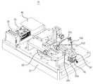
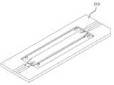
도 1은 본 발명에 의한 자기력 흐름을 이용한 MIP(Magnetic Iron Particles)분리 장치의 사시도
도 2는 본 발명에 의한 자기력 흐름을 이용한 MIP(Magnetic Iron Particles)분리 장치에서 플레이트 상의 자석 배치도
도 3은 본 발명에 의한 자기력 흐름을 이용한 MIP(Magnetic Iron Particles)분리 장치에서 플레이트 상의 자석 배치도
도 4는 본 발명에 의한 자기력 흐름을 이용한 MIP(Magnetic Iron Particles)분리 장치에서 플레이트가 편심 직접 구동방식 사시도
도 5는 본 발명에 의한 자기력 흐름을 이용한 MIP(Magnetic Iron Particles)분리 장치에서 플레이트가 직접 구동 방식 사시도
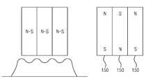
도 6은 본 발명에 의한 자기력 흐름을 이용한 MIP(Magnetic Iron Particles)분리 장치에서 플레이트 상의 반경 방향에 배치된 자석의 개략도
도 7은 본 발명에 의한 자기력 흐름을 이용한 MIP(Magnetic Iron Particles)분리 장치에서 플레이트 상의 원주 방향에 배치된 자석의 개략도
도 8은 본 발명에 바람직한 다른 실시례(벨트 구동 방식)의 사시도
도 9는 본 발명에 바람직한 다른 실시례(독립 벨트 구동 방식)의 사시도
도 10은 본 발명에 바람직한 다른 실시례(벨트 구동 방식)에서의 벨트 상의 자석 배치도
도 11은 본 발명에 의한 자기력 흐름을 이용한 MIP(Magnetic Iron Particles)분리 장치에서 복수의 자석이 결합된 개략도
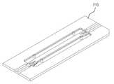
도 12는 본 발명에 의한 자기력 흐름을 이용한 MIP(Magnetic Iron Particles)분리 장치에서 칩의 사시도
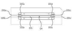
도 13은 본 발명에 의한 자기력 흐름을 이용한 MIP(Magnetic Iron Particles)분리 장치에서 칩의 하판 평면도
도 14는 본 발명에 의한 자기력 흐름을 이용한 MIP(Magnetic Iron Particles)분리 장치에서 칩의 상판 사시도
도 15는 본 발명에 의한 자기력 흐름을 이용한 MIP(Magnetic Iron Particles)분리 장치에서 칩의 사시도
도 16은 본 발명에 의한 자기력 흐름을 이용한 MIP(Magnetic Iron Particles)분리 장치에서 칩의 하판 평면도
도 17은 본 발명에 의한 자기력 흐름을 이용한 MIP(Magnetic Iron Particles)분리 장치에서 칩의 상판 평면도
도 18은 본 발명에 의한 자기력 흐름을 이용한 MIP(Magnetic Iron Particles)분리 장치에서 칩 내부에 형성된 단차의 단면도
도 19는 본 발명에 의한 자기력 흐름을 이용한 MIP(Magnetic Iron Particles)분리 장치에서 칩 내부에 형성된 채널의 단면도
도 20은 본 발명에 의한 자기력 흐름을 이용한 MIP(Magnetic Iron Particles)분리 장치에서 칩과 자석의 배치도1 is a perspective view of a MIP (Magnetic Iron Particles) separating apparatus using a magnetic force flow according to the present invention;
FIG. 2 is a diagram showing a magnetic arrangement of a plate on a MIP (Magnetic Iron Particles) separating apparatus using a magnetic force flow according to the present invention.
FIG. 3 is a view showing a magnetic arrangement of plates on a plate in a MIP (Magnetic Iron Particles) separating apparatus using magnetic force flow according to the present invention
FIG. 4 is a view showing a magnetic separator according to an embodiment of the present invention. FIG.
FIG. 5 is a view illustrating a magnetic separator according to an embodiment of the present invention. FIG.
6 is a schematic view of a magnet disposed in a radial direction on a plate in a MIP (Magnetic Iron Particles) separating apparatus using a magnetic force flow according to the present invention
7 is a schematic view of a magnet disposed in a circumferential direction on a plate in a MIP (Magnetic Iron Particles) separating apparatus using a magnetic force flow according to the present invention
Fig. 8 is a perspective view of another preferred embodiment (belt drive system)
Fig. 9 is a perspective view of another embodiment (independent belt drive system)
Fig. 10 is a diagram showing a magnet layout on a belt in another embodiment (belt drive system)
FIG. 11 is a schematic view of a Magnetic Iron Particles (MIP) separator using a magnetic force flow according to the present invention,
12 is a perspective view of a chip in a MIP (Magnetic Iron Particles) separating apparatus using a magnetic force flow according to the present invention.
13 is a bottom plan view of a chip in a MIP (Magnetic Iron Particles) separating apparatus using a magnetic force flow according to the present invention
14 is a perspective view of a top plate of a chip in a MIP (Magnetic Iron Particles) separating apparatus using a magnetic force flow according to the present invention.
15 is a perspective view of a chip in a MIP (Magnetic Iron Particles) separating apparatus using a magnetic force flow according to the present invention
16 is a plan view of a bottom plate of a chip in a MIP (Magnetic Iron Particles) separating apparatus using a magnetic force flow according to the present invention.
17 is a top plan view of a chip in a MIP (Magnetic Iron Particles) separating apparatus using a magnetic force flow according to the present invention.
18 is a sectional view of a step formed inside a chip in a MIP (Magnetic Iron Particles) separating apparatus using a magnetic force flow according to the present invention
19 is a sectional view of a channel formed in a chip in a MIP (Magnetic Iron Particles) separating apparatus using a magnetic force flow according to the present invention
20 is a diagram showing a layout of a chip and a magnet in a MIP (Magnetic Iron Particles) separating apparatus using a magnetic force flow according to the present invention
이하, 본 발명에 의한 자기력 흐름을 이용한 MIP(Magnetic Iron Particles)분리 장치(10)를 도면을 참조하여 자세히 설명한다.Hereinafter, a MIP (Magnetic Iron Particles) separating
본 발명에 의한 자기력 흐름을 이용한 MIP(Magnetic Iron Particles)분리 장치(10)의 상세한 설명에서 "상"에 있다고 언급되는 경우, 이는 당해 부재에 직접 접촉되어 있거나, 이들 사이에 제3의 부재가 게재될 수 있다는 것을 의미한다.In the description of the MIP (Magnetic Iron Particles) separating
먼저 MIP(Magnetic Iron Particles, 자성 철입자)는 magnetite(Fe3O4), maghemite(gamma Fe2O3), cobalt ferrite, manganese ferrite 등으로 구성되었으며, 구체적인 예로는 magnetic beads, magnetic iron particle beads, magnetic iron nanoparticle beads, superparamagnetic agarose beads 등이 있다.First, Magnetic Iron Particles (MIP) consist of magnetite (Fe3O4), maghemite (gamma Fe2O3), cobalt ferrite and manganese ferrite. Specific examples are magnetic beads, magnetic iron particle beads, magnetic iron nanoparticle beads, superparamagnetic agarose beads.
이하의 설명에서 마그네틱 비드는 MIP의 한 예이다.In the following description, the magnetic bead is an example of MIP.
먼저 칩(200)의 채널(CH)에 유입되는 혼합 용액은 암세포에 특이반응하는 항체가 결합된 자성 나노입자와 검사하고자 하는 혈액을 혼합하여 만든다.First, the mixed solution flowing into the channel (CH) of the chip (200) is prepared by mixing magnetic nanoparticles coupled with antibodies specifically reacting with cancer cells and blood to be examined.
혈액에는 백혈구와 같은 정상 세포들(제 1 물질종, PU), 서로 다른 종류의 암세포A(제 2 물질종, PS1)와 암세포B(제 3 물질종, PS2)을 포함할 수 있다.The blood may include normal cells (first substance species, PU) such as white blood cells, different kinds of cancer cells A (second substance species, PS1), and cancer cells B (third substance species, PS2).
암세포들(PS2, PS3)의 종류가 다를 경우, 암세포에 발현되는 표지자(예를 들면, 항원)의 수가 다르다.When the types of cancer cells (PS2, PS3) are different, the number of markers (for example, antigens) expressed in cancer cells is different.
EpCAM (epithelial cellular adhesion molecule) 표지자의 경우 유방암세포 SKBr-3의 세포당 EpCAM 발현수는 약 500,000개, 전립선암세포 PC3-9의 세포당 EpCAM 발현수는 약 50,000개, 방광암세포 T-24의 세포당 EpCAM 발현수는 약 2,000개 등으로 암종에 따라 1개의 암세포당 발현되는 표지자의 수에 큰 차이가 난다.In the case of EpCAM (epithelial cellular adhesion molecule) markers, the number of EpCAM expression per cell of breast cancer cell SKBr-3 is about 500,000, the number of EpCAM expression per cell of prostate cancer cell PC3-9 is about 50,000, The number of EpCAM expression is approximately 2,000, and the number of markers expressed per cancer cell varies greatly depending on the carcinoma.
따라서 EpCAM에 특이 반응하는 항체를 자성나노입자에 결합시키고 이 자성나노입자와 암환자의 혈액을 혼합하게 되면 암세포의 암 종류에 따라 암세포에 결합되는 자성나노입자의 수에 큰 차이가 발생한다.Therefore, when an antibody reacting specifically with EpCAM is bound to magnetic nanoparticles and the magnetic nanoparticles are mixed with the blood of cancer patients, a large difference occurs in the number of magnetic nanoparticles bound to cancer cells depending on the type of cancer cells.
이와 같이 세포당 결합되는 자성 나노입자의 수 차이는 자기력을 이용하여 암종을 분리하는데 활용된다.Thus, the number of magnetic nanoparticles bound per cell is used to separate carcinomas using magnetic force.
한편, 칩의 완충 용액 투입구(220b)에는 증류수와 같은 완충 용액이 유입된다.On the other hand, a buffer solution such as distilled water flows into the
칩의 완충 용액 투입구(220b)을 통하여 별도로 주입된 완충 용액과 혼합 용액 투입구(220a)에 투입된 혼합 용액은 각자의 속도로 칩(200)의 채널(CH)에서 흐르며 각자의 유동층을 침범하지 않는 듯한 흐름을 보인다.The buffer solution separately injected through the
그러나 자석(150)의 자기력에 의해 마그네틱 비드는 완충 용액 쪽으로 끌려가게 된다.However, the magnetic beads are attracted to the buffer solution by the magnetic force of the
전술한 바와 같이 자성 나노입자 또는 자성 철입자는 마그네틱 비드라 한다.As described above, the magnetic nanoparticles or the magnetic iron particles are referred to as magnetic beads.
칩(200) 하부에는 자기력이 부여된다.A magnetic force is applied to the lower portion of the
자기력은 자성체의 특성을 갖는 어떤 물질도 사용 가능하며, 대표적으로는 Ni, Co, Fe 또는 이들의 화합물들이 사용될 수 있다.Any material having magnetic properties can be used as the magnetic force, and Ni, Co, Fe, or compounds thereof can be used typically.
자기력은 유체 내에서 자성을 띈 입자를 끌어당겨 입자의 흐름을 방해하는 역할을 한다.The magnetic force pulls magnetic particles out of the fluid and interrupts the flow of the particles.
본 발명에 의한 자기력 흐름을 이용한 MIP(Magnetic Iron Particles)분리 장치(10)는 채널(CH)을 포함하는 칩(200)과 칩에 자기력을 부여하는 자석(150)을 포함하여 이루어진다.A MIP (Magnetic Iron Particles)
먼저 자기력 흐름을 이용한 MIP(Magnetic Iron Particles)분리 장치(10)는 베이스(20)를 포함한다.First, the MIP (Magnetic Iron Particles) separating
베이스(20)의 상부에는 턴테이블(60)과 구동부(미도시) 및 Z축 및 각도 조절장치(70)가 형성된다.A
또한 베이스(20)의 상부에는 구동부 제어를 위한 컨트롤러(30)와 드라이브(40) 등이 더 포함되며, 전원공급장치(SMPS,35)가 더 포함된다.The
Z축 및 각도 조절장치(70)의 상부에는 칩 홀더(50)가 결합한다.The
칩 홀더(50)는 그 상부에 결합된 Z축 및 각도 조절장치(70)로부터 플레이트(100)의 중심을 향해 돌출 형성되며, 외팔보 지지구조를 갖는다.The
칩 홀더(50)의 일단은 Z축 및 각도 조절장치(70)의 상부와 결합한다.One end of the
Z축 및 각도 조절장치(70)는 칩 홀더(50)와 뒤에서 설명할 플레이트(100)와의 거리 및 각도를 조절하는 역할을 한다.The Z axis and
칩(200)은 칩 홀더(50)에 놓이게 된다.The
칩(200)에 자기력을 부여하는 자석(150)은 칩(200)에 대해 이동한다.The
또는 칩(200)은 자석(150)에 대해 이동한다.Or the
결국, 칩(200)과 자석(150)은 서로 상대 이동을 한다.As a result, the
도 1을 참고하여 설명하면 다음과 같다.Referring to FIG. 1, the following will be described.
Z축 및 각도 조절장치(70)의 상부에는 칩 홀더의 일단(50a)이 결합한다.One end (50a) of the chip holder is coupled to the upper portion of the Z-axis and angle adjusting device (70).
칩 홀더(50)는 칩 홀더의 중간(50b)부터 칩홀더의 타단(50c)까지 플레이트(100) 상부에 위치하게 된다.The
칩(200)은 플레이트(100) 상부에 위치하는 칩 홀더(50)에 놓여지는데, 구체적으로 칩(200)에 자기력을 부여하기 위해서는 칩(200)은 칩 홀더의 중간(50b)부터 칩홀더의 타단(50c) 사이에 위치함이 바람직하다.The
플레이트(100)는 플레이트(100) 하부에 위치하는 턴테이블(60) 상에 위치하며, 턴테이블(60)은 플레이트(100)를 회전시킨다.The
참고로 턴테이블(60)을 구동하는 방식은 (1) 간접 구동과 (2) 직접 구동의 2가지로 크게 구분할 수 있다.For reference, the method of driving the
간접 구동 방식은 턴테이블(60)이 벨트에 의해 구동되며, 벨트는 풀리와 연결된다.In the indirect drive system, the turntable (60) is driven by a belt, and the belt is connected to a pulley.
풀리는 모터에 의해 구동하는 방식이다.The pulley is driven by a motor.
직접 구동 방식은 턴테이블(60) 하부에 형성되는 모터가 직접 턴테이블(60)을 회전시키는 방식이다.In the direct drive type, the motor formed below the
칩(200)은 플레이트 상부에 위치하는 칩 홀더(50)에 놓여지게 되므로, 반대로 플레이트(100)는 칩(200)의 하부에 형성된다.The
한편 칩(200)에 자기력을 부여하는 자석(150)은 플레이트(100) 상에 형성된다.On the other hand, a
만약 플레이트(100) 상에 자석이 한 개만 형성된 경우, 플레이트(100)의 1 회전당 한번의 자기력만 칩(200)에 부여된다.If only one magnet is formed on the
이러한 구성은 칩(200)의 채널(CH) 내부에서 혼합용액 속에 있는 마그네틱 비드의 분리 속도 측면에서 본 발명의 다른 실시례에 비해 불리하다.This configuration is disadvantageous in comparison with other embodiments of the present invention in terms of the separation speed of the magnetic beads in the mixed solution within the channel CH of the
따라서, 마그네틱 비드의 분리 속도를 증가하기 위해 플레이트(100) 상에 배치되는 자석(150)은 복수 개로 배치하며, 또한 다양한 자석 배치를 갖도록 구성함이 바람직하다.Therefore, in order to increase the separation speed of the magnetic beads, it is preferable that the
자석(150)은 플레이트(100) 상에 복수 개가 형성되도록 한다.A plurality of magnets (150) are formed on the plate (100).
이때, 플레이트(100)의 원주 방향을 따라 배치되는 자석은 하나의 자석과 인접하는 자석 사이에는 자기력의 차이가 존재하며, 이러한 자기력의 차이는 자석(150)과 칩(200) 사이의 높이 차로 구현될 수 있다.At this time, a magnet disposed along the circumferential direction of the
즉, 플레이트(100)의 원주 방향으로 복수 개가 배치된 자석 가운데 하나의 자석을 M1이라고 한다.That is, one magnet among the plurality of magnets arranged in the circumferential direction of the
그리고 M1 보다 플레이트(100)의 원주 방향으로 뒤에 있는 자석을 M2라 한다.And a magnet behind the
플레이트(100)가 회전 운동을 하게 되면, 플레이트(100)의 원주 방향을 따라 복수 개가 배치되는 자석(150)이 칩(200)에 자기력을 부여한다.When the
하나의 마그네틱 비드가 M1의 자기력에 의해 칩의 채널(CH) 내에서 마그네틱 비드 배출구(220c) 방향으로 이동한다.One magnetic bead moves in the direction of the
만약 M1의 후방에 있는 자석인 M2의 자기력이 M1과 같다면, M1의 자기력에 의해 유도되어 분리된 마그네틱 비드는 다시 M2의 자기력에 칩의 채널(CH) 내에서 다시 뒤로 이동하게 된다.If the magnetic force of the magnet M2 at the rear of M1 is equal to M1, the magnetic beads induced by the magnetic force of M1 are moved back to the magnetic force of M2 again in the channel CH of the chip.
즉, 마그네틱 비드가 -
따라서, 마그네틱 비드의 분리를 효율적으로 하기 위해서는 자기력의 세기 조절이 필요하며, 이는 플레이트(100)의 원주 방향으로 따라 복수 개가 배치되는 자석(150)은 하나의 자석을 기준으로 인접하는 자석의 자기력을 서로 달리하여, 예를 들어 자석(150)과 칩(200)과의 높이차를 다르게 함으로써 달성할 수 있다.Accordingly, in order to efficiently separate the magnetic beads, it is necessary to adjust the intensity of the magnetic force. This is because a plurality of
플레이트(100)의 반경 방향을 따라 배치되는 자석은 하나의 자석과 인접하는 자석 사이에는 자기력의 차이가 존재하며, 이러한 자기력의 차이는 자석(150)과 칩(200)의 높이차로 구현될 수 있다.A magnet disposed along the radial direction of the
플레이트(100)의 반경 방향을 기준으로 하나의 자석을 M3라 하고, M3보다 플레이트의 중심에 가까운 자석을 M4라 한다.One magnet is referred to as M3 with respect to the radial direction of the
하나의 마그네틱 비드가 M3을 통과하여 M4의 자기력에 의해 칩의 채널(CH) 내에서 마그네틱 비드 배출구(220c) 방향으로 이동한 경우를 가정한다.It is assumed that one magnetic bead passes through M3 and moves in the direction of the
M4보다 플레이트(100)의 중심에서 멀게 배치된 M3의 자기력이 M4와 같다면, M3을 통과하여 M4의 자기력에 의해 마그네틱 비드 배출구(220c) 방향으로 가야하는 마그네틱 비드가 M3의 자기력에 의해 다시 뒤로 이동하게 된다.If the magnetic force of M3 disposed farther from the center of the
즉, 마그네틱 비드가 +R 방향(플레이트(100)의 중심으로부터 멀어지게 되는 방향)으로 이동하게 되는 백킹 현상(Backing Effect)이 발생하게 된다.That is, a backing effect occurs in which the magnetic beads move in the + R direction (the direction away from the center of the plate 100).
따라서, 마그네틱 비드의 흐름을 원활하게 하기 위해서는 자기력의 세기 조절이 필요하며, 이는 플레이트(100)의 반경 방향으로 따라 복수 개가 배치되는 자석(150)은 하나의 자석을 기준으로 인접하는 자석의 자기력을 달리하여, 예를 들어 자석(150)과 칩(200)과의 높이 차를 다르게 함으로써 달성할 수 있다.Accordingly, in order to smooth the flow of the magnetic bead, it is necessary to adjust the intensity of the magnetic force. This is because a plurality of
턴테이블(60) 상에 위치하는 플레이트(100)는 원판형상을 갖도록 함이 바람직하다.It is preferable that the
이는 턴테이블(60) 상에 위치하는 플레이트(100)가 원판형상일 경우 플레이트(100)의 회전이 용이하고 플레이트(100) 상에 배치되는 복수 개의 자석(150)이 칩(200)에 연속적으로 자기력을 부여하기가 용이하기 때문이다.This is because when the
그러나 플레이트(100)의 형상은 원판형상에 한정되는 것은 아니며, 턴테이블(60) 상에 위치하여 턴테이블(60)의 회전에 따라 플레이트(100)가 회전할 수 있다면, 플레이트(100)의 형상은 사각형상도 가능하다.However, the shape of the
이하에서는 플레이트(100)상에 배치되는 자석(150)의 배치에 대하여 설명한다.Hereinafter, the arrangement of the
(1) 플레이트(100) 상에 배치되는 복수 개의 자석(150)은 제1자석부(150a)를 포함한다.(1) A plurality of
제1자석부(150a)는 플레이트(100) 상에서 플레이트(100)의 직경 방향으로 배치된다.The
제2자석부(150b)는 제1자석부(150a)와 교차 배치되며, 제1자석부(150a)와 제2자석부(150b)는 서로 90도의 각도를 이루며 배치된다.The
마그네틱 비드의 분리 효율을 향상시키기 위해서는 플레이트(100) 상에 배치되는 자석은 제3자석부(150c)와 제4자석부(150d)가 더 포함할 수 있다.In order to improve the separation efficiency of the magnetic beads, the magnet disposed on the
(2) 제3자석부(150c)도 플레이트(100) 상에서 플레이트(100)의 직경 방향으로 배치된다.(2) The
제4자석부(150d)는 제3자석부(150c)와 교차 배치되며, 제3자석부(150c)와 제4자석부(150d)는 서로 90도의 각도를 이루며 배치된다.The
한편 제3자석부(150c)는 전술한 제1자석부(150a)와 제2자석부(150b)의 사이에 배치되므로, 제3자석부(150c)와 서로 90도의 각도를 이루며 배치되는 제4자석부(150d)도 제1자석부(150a)와 제2자석부(150b)의 사이에 배치된다.Meanwhile, since the
이상의 설명에서는 제1자석부(150a)와 제2자석부(150b)가 90도 각도를 이루고, 제3자석부(150c)와 제4자석부(150d)가 서로 90도 각도를 이루는 것으로 설명하고 있으나, 다른 실시례로서 90도가 아닌 다른 각도로 형성될 수 있으며, 또 다른 실시례로서 칩(200)과 자석(150)이 상대 이동하면서 마그네틱 비드의 흐름을 원활하게 하는 경우라면 플레이트(100)상에 그 이외의 추가적인 자석부의 배치도 가능하다.The
마그네틱 비드의 분리 효율 향상을 위해 플레이트(100)의 반경 방향의 폭 범위 내에서 최대한 많은 자석이 설치되는 배치라면 복수 개의 자석(150)을 불규칙적으로 배치할 수도 있다.A plurality of
이상의 설명은 플레이트(100)의 회전 운동은 플레이트(100)의 중심에 대해 이루어짐을 기준으로 한 것이다.The above description is based on the fact that the rotational motion of the
본 발명의 바람직한 다른 실시례에서는 플레이트(100)의 회전 운동은 플레이트(100)의 중심에 대해 편심되어 이루어질 수 있다.In another preferred embodiment of the present invention, the rotational movement of the
즉, 플레이트(100)의 중심과 구동부(80)의 중심이 서로 어긋나게 위치할 경우 구동부(80)의 회전 운동은 플레이트(100)의 편심 회전 운동을 유발한다.That is, when the center of the
도 4에 도시한 편심축(105)은 플레이트(100)의 중심으로부터 편심되어 형성된다.The
플레이트(100)가 구동부(80)에 대해 편심 회전 운동을 하게 될 경우 칩 홀더(50)에 놓여지는 칩(200)에 부여하는 자기력은 플레이트(100)가 편심 회전 운동함에 따라 다르게 힘을 미친다.The magnetic force applied to the
따라서, 전술한 플레이트(100)의 원주 방향 또는 반경 방향으로 자석(150)의 자기력의 차이, 예를 들어 자석(150)의 높이 차를 형성하지 않아도 칩(200)에 부여하는 자기력의 변화가 가능하므로 마그네틱 비드의 분리 효율을 향상할 수 있다.Therefore, it is possible to change the magnetic force given to the
도 5에 도시한 바와 같이 플레이트(100)는 내륜(100b)과 외륜(100a)으로 분리하여 구성할 수 있다.As shown in Fig. 5, the
플레이트(100)는 내륜(100b)과 외륜(100a)으로 분리하는 구성은 내륜(100b)과 외륜(100a)의 회전 방향을 서로 상이하게 할 수 있다.The configuration in which the
이때 내륜(100b)과 외륜(100a)을 구동하는 구동부(80)는 독립 구동 방식으로 구성함이 바람직하다.At this time, the driving
내륜(100b)과 외륜(100a)의 회전 방향이 같을 경우 회전 속도를 상이하게 하여 마그네틱 비드의 분리 효율 및 분리 속도를 향상시킬 수 있다.When the
본 발명에 의한 자기력 흐름을 이용한 MIP(Magnetic Iron Particles)분리 장치(10)에서 이하의 실시례는 벨트(300) 상에 배치된 자석(150)에 의해 마그네틱 비드의 분리를 도모한다.In the following MIP (Magnetic Iron Particles) separating
즉, 칩(200)의 하부에는 벨트(300)가 위치하며, 벨트(300) 상에는 자석(150)이 배치된다.That is, a
벨트(300) 상에 배치되는 자석(150)은 복수 개로 배치하는 것이 마그네틱 비드의 분리 효율상 유리하다.It is advantageous to arrange a plurality of
벨트(300)는 도면을 기준으로 시계 방향 또는 반시계 방향으로 회전할 수 있으며, 이와 같이 벨트(300)는 무한 궤도 운동을 한다.The
벨트(300)가 무한 궤도 운동을 하기 위해 제1풀리(400)와 제2풀리(500)가 벨트(300)의 내측에 위치한다.The
따라서, 벨트(300)는 제1풀리(400)와 제2풀리(500)를 감싸며 배치된다.Thus, the
제1풀리(400) 또는 제2풀리(500)를 구동하여, 제1풀리(400)와 제2풀리(500)를 감싸며 배치된 벨트(300)가 무한 궤도 운동을 하게 된다.The
본 발명의 바람직한 실시례에서는 제2풀리(500)를 구동한다.In a preferred embodiment of the present invention, the
제1풀리(400) 또는 제2풀리(500)에는 구동부(미도시)가 결합되며, 이러한 구동부로는 모터 등의 사용이 바람직하다.A drive unit (not shown) is coupled to the
칩 홀더의 일단(50a)에는 Z축 및 각도 조절 장치(70)가 더 구비된다.The Z-axis and
Z축 및 각도 조절 장치(70)는 칩(200)과 벨트(300) 사이의 거리 또는 각도를 조절하는 역할을 하여 칩(200)에 부여되는 자기력의 세기를 조절할 수 있다.The Z axis and
칩(200)에 부여되는 자기력의 세기를 보다 정밀하게 조절하여, 마그네틱 비드의 유도 효율을 보다 향상시키기 위해 독립 구동방식에 의해 벨트(300)를 무한 궤도 운동을 할 수 있다.The
즉, 칩(200)의 하부에는 위치하는 제1벨트(300a)와 제2벨트(300b)가 위치한다.That is, the first belt 300a and the
제2벨트(300b)는 제1벨트(300a)와 서로 소정 거리만큼 이격되도록 위치하나, 벨트(300)는 칩(200)의 하부에 위치하도록 해야 한다.The
제1벨트(300a)는 구동력을 부여하는 제1구동부(미도시)와 결합한다.The first belt 300a is coupled to a first driving unit (not shown) for imparting driving force.
제2벨트(300b)를 구동력을 부여하는 제2구동부(미도시)와 결합한다.And the
이와 같이 서로 소정 거리만큼 이격되도록 위치하는 제1벨트(300a)와 제2벨트(300b)가 각각 독립적인 구동부와 결합하면, 제1벨트(300a)와 제2벨트(300b)의 무한 궤도 운동 속도는 서로 다르게 조절할 수 있다.When the first belt 300a and the
제1벨트(300a)와 제2벨트(300b)의 무한 궤도 운동 속도를 서로 다르게 독립적으로 제어할 수 있다면 칩 채널(CH) 내부의 마그네틱 비드는 보다 정밀하게 유도 분리될 수 있다.If the infinite orbital movement speeds of the first belt 300a and the
즉, 마그네틱 비드는 칩(200)에 형성된 마그네틱 비드 배출구(220c)에 가까운 쪽에 위치하는 벨트의 무한궤도 운동 속도를, 칩(200)에 형성된 혼합 용액 투입구(220a)에 가까운 쪽에 위치한 벨트의 무한궤도 운동 속도보다 느리게 함으로써, 마그네틱 비드를 마그네틱 비드 배출구(220c) 측으로 보다 정밀하게 유도 분리할 수 있다.That is, the magnetic bead has an infinite orbital movement speed near the
한편 제1벨트(300a)와 제2벨트(300b)의 무한궤도 운동 속도를 동일하게 하면서, 제1벨트(300a)와 제2벨트(300b) 상의 자석(150)의 배치를 서로 달리함으로써 마그네틱 비드를 마그네틱 비드 배출구(220c) 측으로 보다 정밀하게 유도 분리할 수 있다.The first belt 300a and the
벨트(300) 상에는 자석(150)이 복수 개로 배치될 수 있다.A plurality of
하나의 자석과 인접하는 자석과의 가로 방향 이격 거리가 a라고 할 때, 하나의 자석과 인접하는 자석과의 세로 방향 이격 거리는 b라 한다.When the horizontal distance between one magnet and the adjacent magnet is a, the vertical distance between one magnet and the adjacent magnet is b.
이때 a와 b는 동일하게 할 수 있으며, a<b 또는 a>b 와 같이 a와 b를 서로 상이하게 함으로써 벨트(300) 상에 배치되는 자석(150)은 다양하게 배치될 수 있다.In this case, a and b can be the same, and the
벨트(300) 상에는 사선 방향으로 복수 개의 자석이 나란하게 일렬로 배치되며, 일렬로 배치된 하나의 자석과 인접하는 다른 자석과의 거리가 동일한 제5자석부(150e)가 형성된다.On the
이를 통해 칩(200)의 채널(CH)에 자기력이 없는 데드 존(dead zone)을 없앨 수 있다.Thus, a dead zone having no magnetic force in the channel CH of the
제5자석부(150e)와 평행하게 제6자석부(150f)가 배치된다.And a
제5자석부(150e)와 제6자석부(150f)가 평행하게 배치되므로, 제6자석부(150f)도 복수 개의 자석이 나란하게 일렬로 배치되며, 일렬로 배치된 하나의 자석과 인접하는 다른 자석과의 거리가 동일하게 된다.Since the
벨트 상에는 제5자석부(150e)와 제6자석부(150f)가 반복하며 배치된다.The
칩(200)과 자석(150)이 상대 이동하면서 마그네틱 비드의 흐름을 원활하게 하는 경우라면, 마그네틱 비드의 분리 효율 향상을 위해 벨트(300) 상에 대해 복수 개의 자석(150)을 불규칙적으로 배치할 수도 있다.If the
이상의 설명에서 플레이트(100) 상 또는 벨트(200) 상에 배치되는 자석(150)은 복수 개의 자석을 결합하여 형성할 수 있다.(도 11 참고)In the above description, the
즉, 막대형 자석을 기준으로 설명하면 자석의 일단에는 N극과 자석의 타단에는 S극이 형성된다.In other words, when describing a rod-like magnet, an N pole is formed at one end of the magnet and an S pole is formed at the other end of the magnet.
막대형 자석에서의 자기력의 세기는 N극과 S극에서 가장 높게 형성되는 반면, N극과 S극이 만나는 중간 지점은 자기력이 거의 없거나 미미한 수준이다.The magnitude of the magnetic force in the bar magnet is highest in the N and S poles, while the midpoint between the N and S poles has little or no magnetic force.
만약 도면과 같이 복수 개의 자석을 결합하여 하나의 자석으로 사용할 경우 플레이트 상 또는 벨트 상에 배치되는 자석의 설치 공간을 크게 증가시키지 않고 N극과 S극이 만나는 중간 지점에서의 자기력의 세기를 증가시킬 수 있게 된다.If a plurality of magnets are combined to form a single magnet as shown in the drawing, the magnitude of the magnetic force at an intermediate point where the N pole and the S pole meet can be increased without increasing the installation space of the magnet disposed on the plate or the belt .
즉, N극과 S극이 만나는 지점에서는 자기력이 미미하지만 복수 개의 자석이 서로 중첩됨으로써, N극과 S극이 만나는 중간 지점에서의 자기력의 증가가 가능하다.That is, although the magnetic force is small at the point where the N pole and the S pole meet, a plurality of magnets are superimposed on each other, so that the magnetic force can be increased at an intermediate point where the N pole and the S pole meet.
이와 같이 복수 개의 자석을 결합하여 하나의 자석을 형성할 경우, N극과 S극이 만나는 중간 지점에서의 자기력의 세기를 증가시키면서 자기력의 불균일성을 해소하여 마그네틱 비드 유도 및 분리 효율을 향상할 수 있다는 장점이 있다.When a plurality of magnets are combined to form a single magnet, the magnetic bead induction and separation efficiency can be improved by eliminating the non-uniformity of the magnetic force while increasing the intensity of the magnetic force at the midpoint where the N pole and the S pole meet There are advantages.
자기력 흐름을 이용한 MIP(Magnetic Iron Particles)분리 장치에서 칩(200)의 형상은 다음과 같다.The shape of the
칩(200)은 대략적으로 직사각형 평판 형상을 갖는 상판(210)과 하판(220)을 포함하여 이루어진다.The
칩의 상판(210)과 칩의 하판(220)이 결합하여 채널(CH)이 형성된다.The
먼저 칩의 하판(220)에는 내부가 움푹 파인 함몰부(225)와 복수 개의 구멍(220a~220d)이 형성된다.First, the
복수 개의 구멍(220a~220d)은 혼합 용액이 투입되는 혼합 용액 투입구(220a), 식염수 같은 완충 용액이 투입되는 완충 용액 투입구(220a)를 포함한다.The plurality of
칩의 일측(200a)에는 혼합 용액이 투입되는 혼합 용액 투입구(220a), 식염수 같은 완충 용액이 투입되는 완충 용액 투입구(220a)가 형성된다.On one
또한 복수 개의 구멍(220a~220d)은 마그네틱 비드가 배출되는 마그네틱 비드 배출구(220c) 및 기타 입자가 배출되는 기타 입자 배출구(220d)를 포함한다.The plurality of
칩의 타측(200b)에는 마그네틱 비드 배출구(220c) 및 기타 입자가 배출되는 기타 입자 배출구(220d)가 형성된다.The
칩의 하판(220)은 칩의 상판(210)과 결합한다.The
이러한 결합을 통해 칩의 하판(220)에 형성된 함몰부(225)와 칩의 상판(210)의 내측면 사이에 채널(CH)과 복수 개의 통로(225a~225d)를 형성한다.Through this coupling, a channel CH and a plurality of
복수 개의 통로(225a~225d)들은 혼합 용액 투입구(220a)과 채널(CH)을 연결하는 혼합 용액 통로(225a), 버퍼 용액 투입구(220b)와 채널(CH)을 연결하는 버퍼 용액 통로(225b)를 포함한다.The plurality of
복수 개의 통로(225a~225d)들은 또한 마그네틱 비드 배출구(220c)와 채널(CH)을 연결하는 마그네틱 입자 통로(225c) 및 기타 입자 배출구(220d)와 채널(CH)을 연결하는 기타 입자 통로(225d)를 포함한다.The plurality of
전술한 함몰부(225)는 칩의 하판(220)에 형성됨을 기준으로 하였으나, 칩의 상판(210)에 함몰부를 형성할 수 있다.Although the
본 발명에 의한 자기력 흐름을 이용한 MIP(Magnetic Iron Particles)분리 장치에서는 채널(CH)에는 경사가 형성된다.In the MIP (Magnetic Iron Particles) separating apparatus using the magnetic force flow according to the present invention, a slope is formed in the channel CH.
채널(CH)에 마그네틱 비드 배출구(220c) 방향으로 하향 경사를 형성함으로써 마그네틱 비드 분리 속도 및 효율을 향상시킨다.By forming a downward slope in the channel CH in the direction of the
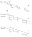
본 발명에 의한 자기력 흐름을 이용한 MIP(Magnetic Iron Particles)분리 장치에서는 채널(CH)에는 마그네틱 비드 배출구(220c) 방향으로 단차(250)가 형성된다.In the MIP (Magnetic Iron Particles) separating apparatus using the magnetic force flow according to the present invention, a
도 19에 도시한 바와 같이 칩(200)을 측면에서 바라볼 경우, 칩(200)의 길이방향으로, 구체적으로 채널(CH)에서 마그네틱 비드 배출구(220c) 방향으로 단차(250)가 형성된다.As shown in FIG. 19, when the
칩의 채널(CH) 내부에서 유동하는 마그네틱 비드가 플레이트(100) 상 또는 벨트(300) 상에 배치된 하나의 자석(M1)에 의해 유도된 후 M1의 후방에 위치하는 자석 M2의 자기력에 의해 다시 뒤로 유동될 수 있다.A magnetic bead flowing inside the channel CH of the chip is guided by one magnet M1 disposed on the
이와 같은 마그네틱 비드의 후방 이동을 방지하기 위해 채널(CH)에 도 16에 도시한 바와 같은 단차(250)를 형성한다.A
채널(CH)에 형성된 단차(250)에 의해 마그네틱 비드가 후방으로 다시 이동하는 현상(백킹 효과, Backing Effect)을 방지할 수 있다.It is possible to prevent the phenomenon that the magnetic beads move backward (backing effect) by the
본 발명에 의한 자기력 흐름을 이용한 MIP(Magnetic Iron Particles)분리 장치에서는 칩(200)의 채널(CH)에 경사와 단차(250)를 조합하여 형성할 수 있다. In the MIP (Magnetic Iron Particles) separating apparatus using the magnetic force flow according to the present invention, the inclination and the
이와 같이 채널(CH)에 경사와 단차(250)를 조합하여 형성할 경우, 마그네틱 비드의 유동 흐름상에서 마그네틱 비드 분리 속도 및 효율을 향상할 수 있을 뿐만 아니라 마그네틱 비드가 후방으로 다시 이동하는 현상(백킹 효과, Backing Effect)을 방지할 수 있다.When the inclination and the
채널(CH)은 칩의 상판(210) 또는 칩의 하판(220)에 형성된 함몰부(225)에 의해 형성된다.The channel CH is formed by a
전술한 바와 같이 함몰부(225)는 칩의 상판(210) 또는 칩의 하판(220)에 형성할 수 있다.As described above, the
만약 채널(CH)의 높이를 칩(200)의 길이 방향에 대해 일정하도록 유지한다면 채널(CH) 내부에서의 유속의 변화를 줄일 수 있다.If the height of the channel CH is kept constant with respect to the longitudinal direction of the
이와 같이 채널(CH) 내부에서의 유속의 변화를 감소시킬 경우 마그네틱 비드의 분리 효율이 향상됨은 자명하다.It is obvious that the separation efficiency of the magnetic beads is improved when the change of the flow rate in the channel CH is reduced.
본 발명에 의한 자기력 흐름을 이용한 MIP(Magnetic Iron Particles)분리 장치(10)에서는 칩(200)은 상판(210)과 상판(210)과 결합하는 하판(220)을 포함하여 이루어진다.In the MIP (Magnetic Iron Particles) separating
채널(CH)은 칩의 상판(21) 또는 칩의 하판(220)에 형성되는 단차(250)를 더 포함한다.The channel CH further includes a
채널(CH)의 높이는 칩(200)의 길이 방향에 대해 일정하도록 한다.The height of the channel CH is made constant with respect to the longitudinal direction of the
채널(CH) 내부에 칩의 상판(210) 또는 칩의 하판(220)에 형성되는 단차(250)가 포함될 경우 채널(CH)의 높이를 칩의 길이 방향에 대해 일정하게 유지하기 위해서는 칩의 하판(220)에 형성된 단차(250)와 부합하는 단차(250)를 칩의 상판(210)에도 형성해야 한다.In order to keep the height of the channel CH constant with respect to the longitudinal direction of the chip when the
칩(200)은 자석(150)에 대하여 기울여 배치될 수 있다.The
전술한 바와 같이 칩(200)은 플레이트(100) 또는 벨트(300) 위에 위치하는 칩 홀더(50)에 위치하며, 칩(200)과 플레이트(100) 상 또는 벨트(300) 상에 배치되는 자석(150)은 서로 평행하게 위치하는 것이 기본이다.The
그러나 마그네틱 비드가 플레이트(100) 상 또는 벨트(300) 상에 배치되는 복수 개의 자석(150) 사이에서 자기력의 간섭에 의해 채널(CH)에서의 흐름이 원활하지 않을 수가 있다.However, the magnetic beads may not flow smoothly in the channel CH due to magnetic interference between the plurality of
즉, 마그네틱 비드를 혼합 용액 내에서 원하는 방향으로 유도하는 과정에서 마그네틱 비드에 작용하는 자력이 동일할 경우 채널(CH)에서의 흐름이 원활하지 않다.That is, when the magnetic beads have the same magnetic force in the course of inducing the magnetic beads in a desired direction in the mixed solution, the flow in the channel CH is not smooth.
따라서, 칩(200)을 기준으로 길이방향, 더욱 구체적으로는 마그네틱 비드 배출구(220c)로 작용하는 자력은 혼합 용액 통로(225a)에 작용하는 자력보다 자력의 세기를 크게 할 필요가 있다.Therefore, it is necessary that the magnetic force acting on the
혼합 용액 통로(225a)에 작용하는 자력보다 마그네틱 비드 배출구(220c)에 작용하는 자력을 크게 할 수 있도록 칩(200)을 자석(150)에 대하여 하향의 기울기를 부여할 수 있다.The
이와 같이 칩(200)을 자석(150)에 대하여 하향의 기울기를 부여하여 배치할 경우에는 혼합 용액 통로(225a)에 작용하는 자력보다 마그네틱 비드 배출구(220c)에 작용하는 자력을 크게 할 수 있다.When the
따라서, 빠른 속도로 마그네틱 비드를 마그네틱 비드 배출구(220c)로 유도할 수 있다.Therefore, the magnetic bead can be guided to the
칩(200)을 자석(150)에 대하여 상향의 기울기를 부여하여 배치할 경우에는 혼합 용액 통로(225a)에 작용하는 자력보다 마그네틱 비드 배출구(220c)에 작용하는 자력을 작게 할 수 있다.The magnetic force acting on the
이와 같이 배치할 경우에는 마그네틱 비드를 마그네틱 비드 배출구(220c)로 보다 정밀하게 유도할 수 있다.In this arrangement, the magnetic bead can be more accurately guided by the
도 20에 도시한 바와 같이 칩(200)은 칩 홀더(50)에 놓여지게 되므로 칩 홀더(50)의 기울려짐은 칩(200)이 기울려짐과 같다.As shown in FIG. 20, since the
본 발명이 속하는 기술 분야에서 통상의 지식을 가진 자는 본 발명이 본 발명의 본질적인 특성에서 벗어나지 않는 범위에서 변형된 형태로 구현될 수 있음을 이해할 수 있을 것이다. 그러므로 개시된 실시예들은 한정적인 관점이 아니라 설명적인 관점에서 고려되어야 한다. 본 발명의 범위는 전술한 설명이 아니라 특허청구범위에 나타나 있으며, 그와 동등한 범위 내에 있는 모든 차이점은 본 발명에 포함된 것으로 해석되어야 할 것이다.It will be understood by those skilled in the art that various changes in form and details may be made therein without departing from the spirit and scope of the invention as defined by the appended claims. Therefore, the disclosed embodiments should be considered in an illustrative rather than a restrictive sense. The scope of the present invention is defined by the appended claims rather than by the foregoing description, and all differences within the scope of equivalents thereof should be construed as being included in the present invention.
또한 본 발명에서 개시된 여러가지 실시예는 다양하게 조합하여 실시할 수 있다.In addition, various embodiments disclosed in the present invention can be implemented in various combinations.
본 발명에 의한 자기력 흐름을 이용한 MIP(Magnetic Iron Particles)분리 장치는 마그네틱 비드 분리 효율이 높을 뿐만 아니라, 칩의 제조 단가가 낮아 경제적이다.The MIP (Magnetic Iron Particles) separating apparatus using the magnetic force flow according to the present invention is not only high in magnetic bead separating efficiency but also economical because the manufacturing cost of the chip is low.
10 : 분리 장치
20 : 베이스30 : 컨틀로러
40 : 드라이버50 : 칩 홀더
60 : 턴테이블70 : Z축 및 각도 조절장치
100 : 플레이트150 : 자석
150a : 제1자석부150b : 제2자석부
150c : 제3자석부150d : 제4자석부
150e : 제5자석부150f : 제6자석부
200 : 칩210 : 칩의 상판
220 : 칩의 하판220a : 혼합 용액 투입구
220b완충 용액 투입구220c : 마그네틱 비드 배출구
220d : 기타 입자 배출구250 : 단차
300 : 벨트400 : 제1풀리
500 : 제2풀리10: Separation device
20: Base 30: Controller
40: driver 50: chip holder
60: turntable 70: Z axis and angle adjusting device
100: Plate 150: Magnet
150a:
150c:
150e:
200: chip 210: chip top plate
220: lower plate of
220b
220d: Other particle outlet 250: Step
300: Belt 400: First pulley
500: second pulley
Claims (21)
Translated fromKorean상기 칩에 자기력을 부여하는 자석;을 포함하며,
상기 자석과 상기 칩은 서로 상대 이동을 하되,
상기 칩의 일측에는 혼합 용액 투입구와 완충 용액 투입구가 형성되며,
상기 칩의 타측에는 마그네틱 비드 배출구와 기타 입자 배출구가 형성된 것을 특징으로 하는 자기력 흐름을 이용한 MIP(Magnetic Iron Particles)분리 장치A chip including a channel;
And a magnet for applying a magnetic force to the chip,
The magnet and the chip are moved relative to each other,
A mixed solution inlet and a buffer solution inlet are formed on one side of the chip,
And a magnetic bead outlet and another particle outlet are formed on the other side of the chip. The MIP (Magnetic Iron Particles) separator
상기 칩의 하부에는 플레이트가 형성되며,
상기 자석은 상기 플레이트 상에 형성되되,
상기 플레이트는 회전 운동을 하는 것을 특징으로 하는 자기력 흐름을 이용한 MIP(Magnetic Iron Particles)분리 장치The method according to claim 1,
A plate is formed under the chip,
The magnet being formed on the plate,
Characterized in that the plate is made to rotate. The magnetic iron particles (MIP)
상기 자석은 상기 플레이트 상에 복수 개가 형성되고,
상기 자석은 상기 플레이트의 원주 또는 반경 방향을 따라 배치되되,
하나의 자석과 인접하는 자석 사이에는 자기력의 차이가 있는 것을 특징으로 하는 자기력 흐름을 이용한 MIP(Magnetic Iron Particles)분리 장치The method of claim 2,
A plurality of magnets are formed on the plate,
The magnet is disposed along the circumference or radial direction of the plate,
Characterized in that there is a difference in magnetic force between one magnet and adjacent magnets, and a magnetic iron particle (MIP) separator
상기 자기력의 차이는 하나의 자석과 인접하는 자석과의 높이 차 또는 하나의 자석과 인접하는 자석의 크기 차에 의해 이뤄지는 것을 특징으로 하는 자기력 흐름을 이용한 MIP(Magnetic Iron Particles)분리 장치The method of claim 3,
Wherein the difference in magnetic force is caused by a height difference between one magnet and a neighboring magnet or a difference in magnitude between adjacent ones of the magnets, and a magnetic iron particle (MIP)
상기 플레이트는 원판이며,
상기 플레이트 상에 배치되는 상기 자석은 제1자석부;
상기 제1자석부와 교차 배치되는 제2자석부를 포함하여 이루어지는 것을 특징으로 하는 자기력 흐름을 이용한 MIP(Magnetic Iron Particles)분리 장치The method of claim 3,
The plate is a disc,
The magnet disposed on the plate includes a first magnet portion;
And a second magnet portion disposed to intersect with the first magnet portion. The Magnetic Iron Particles (MIP)
상기 제1자석부와 상기 제2자석부 사이에 배치되는 제3자석부를 포함하되,
상기 제3자석부와 교차 배치되는 제4자석부를 포함하여 이루어지는 것을 특징으로 하는 자기력 흐름을 이용한 MIP(Magnetic Iron Particles)분리 장치The method of claim 5,
And a third magnet portion disposed between the first magnet portion and the second magnet portion,
And a fourth magnet portion disposed to intersect with the third magnet portion. The Magnetic Iron Particles Separator (MIP)
상기 자석은 상기 플레이트 상에 불규칙적으로 배치되는 것을 특징으로 하는 자기력 흐름을 이용한 MIP(Magnetic Iron Particles)분리 장치The method of claim 3,
Characterized in that the magnets are irregularly arranged on the plate. The Magnetic Iron Particles (MIP)
상기 플레이트는 상기 플레이트의 중심에 대해 편심 회전 운동을 하는 것을 특징으로 하는 자기력 흐름을 이용한 MIP(Magnetic Iron Particles)분리 장치The method of claim 2,
Characterized in that the plate is eccentrically rotated with respect to the center of the plate, characterized in that a magnetic iron particle (MIP)
상기 칩의 하부에 위치하는 벨트;
상기 자석은 상기 벨트 상에 배치되는 것을 특징으로 하는 자기력 흐름을 이용한 MIP(Magnetic Iron Particles)분리 장치The method according to claim 1,
A belt positioned below the chip;
Characterized in that the magnet is disposed on the belt. ≪ RTI ID = 0.0 >
상기 벨트는 제1풀리와 제2풀리를 감싸며 배치되며,
상기 제1풀리 또는 상기 제2풀리를 구동하는 구동부가 더 포함된 것을 특징으로 하는 자기력 흐름을 이용한 MIP(Magnetic Iron Particles)분리 장치The method of claim 9,
The belt is disposed around the first pulley and the second pulley,
And a drive unit for driving the first pulley or the second pulley. The Magnetic Iron Particles (MIP)
상기 벨트는 상기 칩의 하부에 위치하는 제1벨트;
상기 제1벨트로부터 소정 거리만큼 이격되며, 상기 칩의 하부에 위치하는 제2벨트;를 포함하는 것을 특징으로 하는 자기력 흐름을 이용한 MIP(Magnetic Iron Particles)분리 장치The method of claim 9,
The belt comprising: a first belt positioned below the chip;
And a second belt spaced apart from the first belt by a predetermined distance and positioned at a lower portion of the chip, wherein the MIP (Magnetic Iron Particles)
상기 제1벨트를 구동하는 제1구동부;
상기 제2벨트를 구동하는 제2구동부를 더 포함하는 것을 특징으로 하는 자기력 흐름을 이용한 MIP(Magnetic Iron Particles)분리 장치The method of claim 11,
A first driving unit for driving the first belt;
And a second driving unit for driving the second belt. The Magnetic Iron Particles Separator (MIP)
상기 벨트 상에 상기 자석은 복수 개로 배치되며,
하나의 자석과 인접하는 자석과의 가로 방향 이격 거리는 a이며, 세로 방향 이격 거리는 b인 것을 특징으로 하는 자기력 흐름을 이용한 MIP(Magnetic Iron Particles)분리 장치The method of claim 9,
Wherein the plurality of magnets are disposed on the belt,
Characterized in that a horizontal separation distance between one magnet and a neighboring magnet is a, and a vertical separation distance is b. A magnetic iron particle (MIP) separation device
사선 방향으로 복수 개의 자석이 나란하게 일렬로 배치되며, 일렬로 배치된 하나의 자석과 인접하는 다른 자석과의 거리가 동일한 제5자석부;
상기 제5자석부와 평행하게 배치되는 제6자석부;를 더 포함하되,
상기 제5자석부와 제6자석부가 반복 배치되는 것을 특징으로 하는 자기력 흐름을 이용한 MIP(Magnetic Iron Particles)분리 장치The method according to claim 9 or 11,
A fifth magnet portion arranged in a line in a line in the oblique direction with a plurality of magnets arranged side by side and having a distance from one magnet arranged in a row to another adjacent magnet;
And a sixth magnet portion disposed parallel to the fifth magnet portion,
And the fifth magnet portion and the sixth magnet portion are repeatedly arranged. The Magnetic Particles Separator (MIP)
상기 자석은 상기 벨트 상에 복수 개로 불규칙하도록 배치되는 것을 특징으로 하는 자기력 흐름을 이용한 MIP(Magnetic Iron Particles)분리 장치The method of claim 9,
Wherein the magnets are arranged on the belt irregularly in a plurality of MIP (Magnetic Iron Particles)
상기 자석은 복수 개의 자석이 결합하며 형성된 것을 특징으로 하는 자기력 흐름을 이용한 MIP(Magnetic Iron Particles)분리 장치The method according to any one of claims 1 to 15,
Wherein the magnet is formed by combining a plurality of magnets. The Magnetic Iron Particles (MIP)
상기 채널에는 경사가 형성된 것을 특징으로 하는 자기력 흐름을 이용한 MIP(Magnetic Iron Particles)분리 장치The method according to claim 1,
And a slant is formed in the channel. The Magnetic Iron Particles (MIP)
상기 채널에는 단차가 형성된 것을 특징으로 하는 자기력 흐름을 이용한 MIP(Magnetic Iron Particles)분리 장치The method according to claim 1,
Characterized in that a stepped portion is formed in the channel, and a magnetic iron particle (MIP)
상기 채널에는 경사 및 단차가 형성된 것을 특징으로 하는 자기력 흐름을 이용한 MIP(Magnetic Iron Particles)분리 장치The method according to claim 1,
And a slope and a step are formed in the channel. The Magnetic Iron Particles (MIP)
상기 칩은 상판과 상기 상판과 결합하는 하판을 포함하여 이루어지며,
상기 채널은 상기 칩의 상판 또는 상기 칩의 하판에 형성되는 단차를 더 포함하되, 상기 채널의 높이는 상기 칩의 길이 방향에 대해 일정한 것을 특징으로 하는 자기력 흐름을 이용한 MIP(Magnetic Iron Particles)분리 장치The method according to claim 1,
The chip includes an upper plate and a lower plate coupled with the upper plate,
Wherein the channel further comprises a step formed on an upper plate of the chip or a lower plate of the chip, wherein a height of the channel is constant with respect to a longitudinal direction of the chip, wherein the channel is formed by a Magnetic Iron Particles
상기 칩은 상기 자석에 대하여 기울여 배치된 것을 특징으로 하는 자기력 흐름을 이용한 MIP(Magnetic Iron Particles)분리 장치The method according to claim 1,
Characterized in that the chip is disposed obliquely with respect to the magnet. The MIP (Magnetic Iron Particles) separating device
Priority Applications (2)
| Application Number | Priority Date | Filing Date | Title |
|---|---|---|---|
| KR1020150101986AKR101720609B1 (en) | 2015-07-17 | 2015-07-17 | MIP(Magnetic Iron Particles) Discrimination Device Using Magnetic Force Flow |
| KR1020170031347AKR102270402B1 (en) | 2015-07-17 | 2017-03-13 | MIP(Magnetic Iron Particles) Discrimination Device Using Magnetic Force Flow |
Applications Claiming Priority (1)
| Application Number | Priority Date | Filing Date | Title |
|---|---|---|---|
| KR1020150101986AKR101720609B1 (en) | 2015-07-17 | 2015-07-17 | MIP(Magnetic Iron Particles) Discrimination Device Using Magnetic Force Flow |
Related Child Applications (1)
| Application Number | Title | Priority Date | Filing Date |
|---|---|---|---|
| KR1020170031347ADivisionKR102270402B1 (en) | 2015-07-17 | 2017-03-13 | MIP(Magnetic Iron Particles) Discrimination Device Using Magnetic Force Flow |
Publications (2)
| Publication Number | Publication Date |
|---|---|
| KR20170009649Atrue KR20170009649A (en) | 2017-01-25 |
| KR101720609B1 KR101720609B1 (en) | 2017-03-28 |
Family
ID=57991543
Family Applications (1)
| Application Number | Title | Priority Date | Filing Date |
|---|---|---|---|
| KR1020150101986AActiveKR101720609B1 (en) | 2015-07-17 | 2015-07-17 | MIP(Magnetic Iron Particles) Discrimination Device Using Magnetic Force Flow |
Country Status (1)
| Country | Link |
|---|---|
| KR (1) | KR101720609B1 (en) |
Cited By (1)
| Publication number | Priority date | Publication date | Assignee | Title |
|---|---|---|---|---|
| CN111239380A (en)* | 2018-11-29 | 2020-06-05 | 深圳华迈兴微医疗科技有限公司 | Chemiluminescence immunoassay appearance |
Citations (7)
| Publication number | Priority date | Publication date | Assignee | Title |
|---|---|---|---|---|
| JPH11156231A (en)* | 1997-09-29 | 1999-06-15 | F Hoffmann La Roche Ag | Apparatus for separating suspended magnetic particles in liquid |
| JP2004226234A (en)* | 2003-01-23 | 2004-08-12 | Hitachi Software Eng Co Ltd | Functional beads, reading method therefor, and reading apparatus therefor |
| JP2009226281A (en)* | 2008-03-21 | 2009-10-08 | Kotobuki Sangyo Kk | Magnetic sorting apparatus |
| KR101211862B1 (en) | 2012-04-30 | 2012-12-12 | 한국기계연구원 | Apparatus for self-extracting cells using magnetic force and method for self-extracting cells using the same |
| KR101212030B1 (en) | 2012-04-30 | 2012-12-13 | 한국기계연구원 | Apparatus for separating cells using magnetic force and method for separating cells using the same |
| KR20130095485A (en) | 2012-02-20 | 2013-08-28 | 강문수 | A process for preventing a concrete carbonation anddeterioration |
| KR20130103282A (en) | 2012-03-09 | 2013-09-23 | 한국전자통신연구원 | Multiple discrimination device and method for tumor discrimination |
- 2015
- 2015-07-17KRKR1020150101986Apatent/KR101720609B1/enactiveActive
Patent Citations (7)
| Publication number | Priority date | Publication date | Assignee | Title |
|---|---|---|---|---|
| JPH11156231A (en)* | 1997-09-29 | 1999-06-15 | F Hoffmann La Roche Ag | Apparatus for separating suspended magnetic particles in liquid |
| JP2004226234A (en)* | 2003-01-23 | 2004-08-12 | Hitachi Software Eng Co Ltd | Functional beads, reading method therefor, and reading apparatus therefor |
| JP2009226281A (en)* | 2008-03-21 | 2009-10-08 | Kotobuki Sangyo Kk | Magnetic sorting apparatus |
| KR20130095485A (en) | 2012-02-20 | 2013-08-28 | 강문수 | A process for preventing a concrete carbonation anddeterioration |
| KR20130103282A (en) | 2012-03-09 | 2013-09-23 | 한국전자통신연구원 | Multiple discrimination device and method for tumor discrimination |
| KR101211862B1 (en) | 2012-04-30 | 2012-12-12 | 한국기계연구원 | Apparatus for self-extracting cells using magnetic force and method for self-extracting cells using the same |
| KR101212030B1 (en) | 2012-04-30 | 2012-12-13 | 한국기계연구원 | Apparatus for separating cells using magnetic force and method for separating cells using the same |
Cited By (1)
| Publication number | Priority date | Publication date | Assignee | Title |
|---|---|---|---|---|
| CN111239380A (en)* | 2018-11-29 | 2020-06-05 | 深圳华迈兴微医疗科技有限公司 | Chemiluminescence immunoassay appearance |
Also Published As
| Publication number | Publication date |
|---|---|
| KR101720609B1 (en) | 2017-03-28 |
Similar Documents
| Publication | Publication Date | Title |
|---|---|---|
| US6253924B1 (en) | Magnetic separator apparatus and methods regarding same | |
| KR101583017B1 (en) | MIP(Magnetic Iron Particles) Discrimination System | |
| CN103476504B (en) | Device for continuous separation of magnetic components and cleaning of magnetic parts | |
| US8951782B2 (en) | Apparatus for separating cells using magnetic force and cell separation method using the same | |
| KR101720609B1 (en) | MIP(Magnetic Iron Particles) Discrimination Device Using Magnetic Force Flow | |
| CN1297380A (en) | Continuous magnetic separation of mixture components | |
| KR101667351B1 (en) | Disposable Discrimination Chip | |
| US10317397B2 (en) | Microparticle separation chip, and microparticle separation system and microparticle separation method which employ said microparticle separation chip | |
| KR20170032265A (en) | MIP(Magnetic Iron Particles) Discrimination Device Using Magnetic Force Flow | |
| CN205323978U (en) | Permanent magnetism pipeline magnet separator | |
| KR101391810B1 (en) | Polishing system using MR fluid | |
| Rampini et al. | Micromagnet arrays for on-chip focusing, switching, and separation of superparamagnetic beads and single cells | |
| CN202191960U (en) | Permanent magnetic orthogonal magnetic separator adopting combined magnetic system | |
| KR102037891B1 (en) | Multiple discrimination device and method for tumor discrimination | |
| CN106362863A (en) | Strongly magnetic mineral accurate magnetic separation method | |
| CN202825549U (en) | Grinding pad collator and grinding device | |
| CN209387365U (en) | Rock sampling grinder for geotechnical engineering | |
| Ke et al. | Isolation of circulating tumor cells based on magnetophoresis | |
| CN205146437U (en) | Device that carries out continuous deironing to flowable nature material | |
| CN107401841B (en) | A kind of apparatus and method of magnetic control burning chemistry chains reaction | |
| KR102423482B1 (en) | Divice for separating circulating tumor cells and method for diagnosing cancer using the same | |
| GB1559338A (en) | Method and device for the wet magnetic dressing of fine gred solid | |
| KR20160017282A (en) | Circulating tumor cells sorting chip | |
| CN108435413B (en) | A kind of poly- magnetic scraper plate annular movement magnetic system magnetic separator | |
| Yang et al. | Engineered iron oxide nanoplatforms: reprogramming immunosuppressive niches for precision cancer theranostics |
Legal Events
| Date | Code | Title | Description |
|---|---|---|---|
| A201 | Request for examination | ||
| PA0109 | Patent application | Patent event code:PA01091R01D Comment text:Patent Application Patent event date:20150717 | |
| PA0201 | Request for examination | ||
| E902 | Notification of reason for refusal | ||
| PE0902 | Notice of grounds for rejection | Comment text:Notification of reason for refusal Patent event date:20161220 Patent event code:PE09021S01D | |
| PG1501 | Laying open of application | ||
| E701 | Decision to grant or registration of patent right | ||
| PE0701 | Decision of registration | Patent event code:PE07011S01D Comment text:Decision to Grant Registration Patent event date:20170228 | |
| PA0107 | Divisional application | Comment text:Divisional Application of Patent Patent event date:20170313 Patent event code:PA01071R01D | |
| GRNT | Written decision to grant | ||
| PR0701 | Registration of establishment | Comment text:Registration of Establishment Patent event date:20170322 Patent event code:PR07011E01D | |
| PR1002 | Payment of registration fee | Payment date:20170323 End annual number:3 Start annual number:1 | |
| PG1601 | Publication of registration | ||
| PR1001 | Payment of annual fee | Payment date:20200623 Start annual number:4 End annual number:4 | |
| PR1001 | Payment of annual fee | Payment date:20210122 Start annual number:5 End annual number:5 | |
| PR1001 | Payment of annual fee | Payment date:20220307 Start annual number:6 End annual number:6 | |
| PR1001 | Payment of annual fee | Payment date:20230308 Start annual number:7 End annual number:7 | |
| PR1001 | Payment of annual fee | Payment date:20240311 Start annual number:8 End annual number:8 |