KR20170007491A - Plastic optical fiber for reliable low-cost avionic networks - Google Patents
Plastic optical fiber for reliable low-cost avionic networksDownload PDFInfo
- Publication number
- KR20170007491A KR20170007491AKR1020167036966AKR20167036966AKR20170007491AKR 20170007491 AKR20170007491 AKR 20170007491AKR 1020167036966 AKR1020167036966 AKR 1020167036966AKR 20167036966 AKR20167036966 AKR 20167036966AKR 20170007491 AKR20170007491 AKR 20170007491A
- Authority
- KR
- South Korea
- Prior art keywords
- flight control
- optical fiber
- plastic optical
- signal transmission
- control computer
- Prior art date
- Legal status (The legal status is an assumption and is not a legal conclusion. Google has not performed a legal analysis and makes no representation as to the accuracy of the status listed.)
- Granted
Links
Images


Classifications
- F—MECHANICAL ENGINEERING; LIGHTING; HEATING; WEAPONS; BLASTING
- F03—MACHINES OR ENGINES FOR LIQUIDS; WIND, SPRING, OR WEIGHT MOTORS; PRODUCING MECHANICAL POWER OR A REACTIVE PROPULSIVE THRUST, NOT OTHERWISE PROVIDED FOR
- F03D—WIND MOTORS
- F03D13/00—Assembly, mounting or commissioning of wind motors; Arrangements specially adapted for transporting wind motor components
- F03D13/20—Arrangements for mounting or supporting wind motors; Masts or towers for wind motors
- F—MECHANICAL ENGINEERING; LIGHTING; HEATING; WEAPONS; BLASTING
- F03—MACHINES OR ENGINES FOR LIQUIDS; WIND, SPRING, OR WEIGHT MOTORS; PRODUCING MECHANICAL POWER OR A REACTIVE PROPULSIVE THRUST, NOT OTHERWISE PROVIDED FOR
- F03D—WIND MOTORS
- F03D1/00—Wind motors with rotation axis substantially parallel to the air flow entering the rotor
- F03D1/02—Wind motors with rotation axis substantially parallel to the air flow entering the rotor having a plurality of rotors
- F—MECHANICAL ENGINEERING; LIGHTING; HEATING; WEAPONS; BLASTING
- F03—MACHINES OR ENGINES FOR LIQUIDS; WIND, SPRING, OR WEIGHT MOTORS; PRODUCING MECHANICAL POWER OR A REACTIVE PROPULSIVE THRUST, NOT OTHERWISE PROVIDED FOR
- F03D—WIND MOTORS
- F03D7/00—Controlling wind motors
- F03D7/02—Controlling wind motors the wind motors having rotation axis substantially parallel to the air flow entering the rotor
- F03D7/04—Automatic control; Regulation
- F03D7/042—Automatic control; Regulation by means of an electrical or electronic controller
- F03D7/047—Automatic control; Regulation by means of an electrical or electronic controller characterised by the controller architecture, e.g. multiple processors or data communications
- F03D9/003—
- F—MECHANICAL ENGINEERING; LIGHTING; HEATING; WEAPONS; BLASTING
- F03—MACHINES OR ENGINES FOR LIQUIDS; WIND, SPRING, OR WEIGHT MOTORS; PRODUCING MECHANICAL POWER OR A REACTIVE PROPULSIVE THRUST, NOT OTHERWISE PROVIDED FOR
- F03D—WIND MOTORS
- F03D9/00—Adaptations of wind motors for special use; Combinations of wind motors with apparatus driven thereby; Wind motors specially adapted for installation in particular locations
- F03D9/20—Wind motors characterised by the driven apparatus
- F03D9/25—Wind motors characterised by the driven apparatus the apparatus being an electrical generator
- F03D9/255—Wind motors characterised by the driven apparatus the apparatus being an electrical generator connected to electrical distribution networks; Arrangements therefor
- F—MECHANICAL ENGINEERING; LIGHTING; HEATING; WEAPONS; BLASTING
- F03—MACHINES OR ENGINES FOR LIQUIDS; WIND, SPRING, OR WEIGHT MOTORS; PRODUCING MECHANICAL POWER OR A REACTIVE PROPULSIVE THRUST, NOT OTHERWISE PROVIDED FOR
- F03D—WIND MOTORS
- F03D9/00—Adaptations of wind motors for special use; Combinations of wind motors with apparatus driven thereby; Wind motors specially adapted for installation in particular locations
- F03D9/30—Wind motors specially adapted for installation in particular locations
- F03D9/32—Wind motors specially adapted for installation in particular locations on moving objects, e.g. vehicles
- F03D9/322—Wind motors specially adapted for installation in particular locations on moving objects, e.g. vehicles the wind motors being supported in air by airborne structures, e.g. by kites
- F—MECHANICAL ENGINEERING; LIGHTING; HEATING; WEAPONS; BLASTING
- F05—INDEXING SCHEMES RELATING TO ENGINES OR PUMPS IN VARIOUS SUBCLASSES OF CLASSES F01-F04
- F05B—INDEXING SCHEME RELATING TO WIND, SPRING, WEIGHT, INERTIA OR LIKE MOTORS, TO MACHINES OR ENGINES FOR LIQUIDS COVERED BY SUBCLASSES F03B, F03D AND F03G
- F05B2240/00—Components
- F05B2240/90—Mounting on supporting structures or systems
- F05B2240/92—Mounting on supporting structures or systems on an airbourne structure
- F05B2240/921—Mounting on supporting structures or systems on an airbourne structure kept aloft due to aerodynamic effects
- Y—GENERAL TAGGING OF NEW TECHNOLOGICAL DEVELOPMENTS; GENERAL TAGGING OF CROSS-SECTIONAL TECHNOLOGIES SPANNING OVER SEVERAL SECTIONS OF THE IPC; TECHNICAL SUBJECTS COVERED BY FORMER USPC CROSS-REFERENCE ART COLLECTIONS [XRACs] AND DIGESTS
- Y02—TECHNOLOGIES OR APPLICATIONS FOR MITIGATION OR ADAPTATION AGAINST CLIMATE CHANGE
- Y02E—REDUCTION OF GREENHOUSE GAS [GHG] EMISSIONS, RELATED TO ENERGY GENERATION, TRANSMISSION OR DISTRIBUTION
- Y02E10/00—Energy generation through renewable energy sources
- Y02E10/70—Wind energy
- Y02E10/72—Wind turbines with rotation axis in wind direction
- Y02E10/723—
- Y—GENERAL TAGGING OF NEW TECHNOLOGICAL DEVELOPMENTS; GENERAL TAGGING OF CROSS-SECTIONAL TECHNOLOGIES SPANNING OVER SEVERAL SECTIONS OF THE IPC; TECHNICAL SUBJECTS COVERED BY FORMER USPC CROSS-REFERENCE ART COLLECTIONS [XRACs] AND DIGESTS
- Y02—TECHNOLOGIES OR APPLICATIONS FOR MITIGATION OR ADAPTATION AGAINST CLIMATE CHANGE
- Y02E—REDUCTION OF GREENHOUSE GAS [GHG] EMISSIONS, RELATED TO ENERGY GENERATION, TRANSMISSION OR DISTRIBUTION
- Y02E10/00—Energy generation through renewable energy sources
- Y02E10/70—Wind energy
- Y02E10/728—Onshore wind turbines
Landscapes
- Engineering & Computer Science (AREA)
- Life Sciences & Earth Sciences (AREA)
- Sustainable Development (AREA)
- Sustainable Energy (AREA)
- Chemical & Material Sciences (AREA)
- Combustion & Propulsion (AREA)
- Mechanical Engineering (AREA)
- General Engineering & Computer Science (AREA)
- Power Engineering (AREA)
- Wind Motors (AREA)
- Aviation & Aerospace Engineering (AREA)
- Automation & Control Theory (AREA)
Abstract
Translated fromKoreanDescription
Translated fromKorean관련 출원에 대한 상호 참조Cross-reference to related application
본원은 2014년 6월 30일자로 출원된 미국 특허 출원 제14/320,565호의 우선권을 주장하며, 그 전체가 본 명세서에 참고로 포함된다.This application claims priority to U.S. Patent Application No. 14 / 320,565, filed June 30, 2014, which is incorporated herein by reference in its entirety.
본 명세서에서 달리 언급되지 않는 한, 이 섹션에서 설명되는 자료들은 본 출원의 청구항들에 대한 선행 기술이 아니며, 이 섹션에 포함되어 있다고 해서 선행 기술인 것으로 인정되지는 않는다.Unless otherwise stated herein, the materials described in this section are not prior art to the claims of the present application and are not considered to be prior art as included in this section.
전력 발생 시스템들은 화학 및/또는 기계적 에너지(예를 들어, 운동 에너지)를 유틸리티 시스템들과 같은 다양한 응용들을 위한 전기 에너지로 변환할 수 있다. 일례로서, 풍력 에너지 시스템은 풍력 운동 에너지를 전기 에너지로 변환할 수 있다.Power generation systems can convert chemical and / or mechanical energy (e.g., kinetic energy) into electrical energy for a variety of applications such as utility systems. As an example, a wind energy system can convert wind kinetic energy into electrical energy.
에너지를 활용하기 위한 수단으로서의 풍력 터빈들의 사용은 수년 동안 사용되어 왔다. 종래의 풍력 터빈들은 탑의 꼭대기에 배치된 큰 터빈 블레이드들을 통상적으로 포함한다. 이러한 풍력 터빈 탑들 및 풍력 터빈들을 제조하고, 세우고, 유지하고, 정비하는 비용은 상당하다.The use of wind turbines as a means to utilize energy has been used for many years. Conventional wind turbines typically include large turbine blades disposed at the top of the tower. The cost of manufacturing, building, maintaining and servicing these wind turbine towers and wind turbines is substantial.
풍력 에너지를 활용하기 위해 사용될 수 있는 비용이 많이 드는 풍력 터빈 탑들에 대한 대안은 전기 도전성 끈(tether)을 사용하여 지상국에 부착되는 항공기를 사용하는 것이다. 이러한 대안은 공중 풍력 터빈(Airborne Wind Turbine, AWT)이라고 지칭될 수 있다.An alternative to costly wind turbine towers that can be used to utilize wind energy is to use aircraft attached to ground stations using electrically conductive tethers. Such an alternative may be referred to as an Airborne Wind Turbine (AWT).
일 양태에서, 주 날개, 동체, 방향타 및 후방 엘리베이터를 갖는 항공기뿐만 아니라 상기 주 날개에 고정된 복수의 전력 발생 터빈 및 상기 날개 상에 배치된 복수의 보조 날개를 포함하는 공중 풍력 터빈 시스템이 제공된다. 상기 항공기는 신호 전송 매체로서 플라스틱 광섬유를 사용하여 상기 복수의 전력 발생 터빈, 복수의 보조 날개 서보 모터, 복수의 방향타 서보 모터 및 복수의 후방 엘리베이터 서보 모터에 링크되는 제1 및 제2 비행 제어 컴퓨터들을 포함한다. 하나의 링크가 고장날 경우, 상기 비행 제어 컴퓨터들과 네트워크에서 링크된 각각의 구성 요소 간의 백업 링크가 존재하도록 이중 중복 통신 시스템이 제공된다. 상기 중복 통신 시스템 및 신호 전송 매체로서의 플라스틱 광섬유의 사용은 종래의 공중 통신 시스템과 비교할 때 전반적인 시스템 신뢰성, 정비 및 유지의 용이성뿐만 아니라 전반적인 비용을 크게 향상시킨다.In one aspect, an aerial wind turbine system is provided that includes an aircraft having a main wing, a fuselage, a rudder, and a rear elevator, as well as a plurality of power generation turbines secured to the main wing and a plurality of auxiliary wings disposed on the wing . The aircraft includes first and second flight control computers linked to the plurality of power generation turbines, a plurality of auxiliary wing servo motors, a plurality of rudder servomotors and a plurality of rear elevator servomotors using plastic optical fibers as signal transmission media . A redundant communication system is provided in which, when one link fails, there is a backup link between the flight control computers and each component linked in the network. The use of the plastic optical fiber as the redundant communication system and signal transmission medium greatly improves the overall cost as well as the overall system reliability, maintenance and maintenance easiness compared to the conventional public communication system.
또 다른 양태에서, 주 날개를 갖는 항공기, 상기 항공기에 고정된 제1 단부 및 지상국에 고정된 제2 단부를 갖는 전기 도전성 끈, 상기 주 날개에 연결된 복수의 전력 발생 터빈, 제1 비행 제어 컴퓨터를 포함하여, 상기 항공기와 함께 배치된 통신 네트워크, 및 상기 제1 비행 제어 컴퓨터와 상기 복수의 전력 발생 터빈 사이에 연장되는 제1 플라스틱 광섬유 신호 전송 라인들을 포함하는 공중 풍력 터빈 시스템이 제공된다.In another aspect, there is provided an aircraft comprising an aircraft having a main wing, an electrically conductive strap having a first end fixed to the aircraft and a second end fixed to the ground station, a plurality of power generation turbines connected to the main wing, And a first plastic fiber signal transmission lines extending between the first flight control computer and the plurality of power generation turbines are provided.
추가적인 양태에서, 동체 및 주 날개를 갖는 항공기, 상기 항공기에 고정된 제1 단부 및 지상국에 고정된 제2 단부를 갖는 전기 도전성 끈, 상기 주 날개에 연결된 복수의 전력 발생 터빈, 상기 주 날개의 제1 측에 배치된 제1 및 제2 보조 날개, 상기 주 날개의 상기 제1 측으로부터 상기 동체의 반대 측에 있는 상기 주 날개의 제2 측에 배치된 제3 및 제4 보조 날개, 제1 비행 제어 컴퓨터 및 제2 비행 제어 컴퓨터를 포함하여, 상기 항공기와 함께 배치된 통신 네트워크, 상기 제1 비행 제어 컴퓨터와 상기 제1 보조 날개 사이에 연장되는 제1 듀플렉스 플라스틱 광섬유 신호 전송 라인, 상기 제1 보조 날개와 상기 제2 보조 날개 사이에 연장되는 제2 듀플렉스 플라스틱 광섬유 신호 전송 라인, 상기 제1 비행 제어 컴퓨터와 상기 제2 비행 제어 컴퓨터 사이에 연장되는 제3 듀플렉스 플라스틱 광섬유 신호 전송 라인, 상기 제2 비행 제어 컴퓨터와 상기 제2 보조 날개 사이에 연장되는 제4 듀플렉스 플라스틱 광섬유 신호 전송 라인, 상기 제1 보조 날개와 상기 제2 보조 날개 사이에 연장되는 제5 듀플렉스 플라스틱 광섬유 신호 전송 라인, 상기 제2 비행 제어 컴퓨터와 상기 제3 보조 날개 사이에 연장되는 제6 듀플렉스 플라스틱 광섬유 신호 전송 라인, 상기 제3 보조 날개와 상기 제4 보조 날개 사이에 연장되는 제7 듀플렉스 플라스틱 광섬유 신호 전송 라인, 상기 제2 비행 제어 컴퓨터와 상기 제2 보조 날개 사이에 연장되는 제8 듀플렉스 플라스틱 광섬유 신호 전송 라인, 및 상기 제1 보조 날개와 상기 제2 보조 날개 사이에 연장되는 제9 듀플렉스 플라스틱 광섬유 신호 전송 라인을 포함하는 공중 풍력 터빈 시스템이 제공된다.In a further aspect there is provided an aircraft having an airframe and a main wing, an electrically conductive strap having a first end fixed to the aircraft and a second end fixed to the ground station, a plurality of power generation turbines connected to the main wing, First and second auxiliary wings disposed on the second side of the main wing on the opposite side of the fuselage from the first side of the main wing, A communication network disposed with the aircraft, including a control computer and a second flight control computer, a first duplex plastic optical fiber signal transmission line extending between the first flight control computer and the first auxiliary wing, A second duplex plastic optical fiber signal transmission line extending between the wing and the second auxiliary wing, and a second duplex plastic optical fiber signal transmission line extending between the first flight control computer and the second flight control computer A fourth duplex plastic optical fiber signal transmission line extending between the second flight control computer and the second auxiliary wing, a fourth duplex plastic optical fiber signal transmission line extending between the first auxiliary wing and the second auxiliary wing A fifth duplex plastic optical fiber signal transmission line, a sixth duplex plastic optical fiber signal transmission line extending between said second flight control computer and said third auxiliary wing, and a sixth auxiliary plastic optical fiber signal transmission line extending between said third auxiliary wing and said fourth auxiliary wing 7 duplex plastic optical fiber signal transmission line, an eighth duplex plastic optical fiber signal transmission line extending between the second flight control computer and the second auxiliary wing, and an eighth duplex plastic optical fiber signal transmission line extending between the first auxiliary wing and the second auxiliary wing An aerial wind turbine system including a 9-Duplex plastic fiber optic signal transmission line It is.
또 다른 양태에서, 주 날개를 갖는 항공기, 상기 항공기에 고정된 제1 단부 및 지상국에 고정된 제2 단부를 갖는 전기 도전성 끈, 상기 주 날개에 연결된 복수의 전력 발생 터빈, 상기 항공기와 함께 배치된 비행 제어 시스템, 상기 항공기와 함께 배치된 통신 네트워크를 포함하는 공중 풍력 터빈이 제공되고, 상기 비행 제어 시스템은 이중 중복 제1 및 제2 비행 제어 컴퓨터들을 포함하며, 상기 통신 네트워크는 이중 중복 네트워크를 포함하고, 상기 이중 중복 제1 및 제2 비행 제어 컴퓨터들은 상기 이중 중복 통신 네트워크에 연결되고, 상기 제1 및 제2 비행 제어 컴퓨터들은 신호 전송 매체로서 플라스틱 광섬유를 사용하여 상기 통신 네트워크에 그리고 서로에게 링크된다.In another aspect, there is provided an aircraft comprising an aircraft having a main wing, an electrically conductive strap having a first end fixed to the aircraft and a second end fixed to the ground station, a plurality of power generation turbines connected to the main wing, There is provided an aerial wind turbine including a flight control system, a communication network arranged with the aircraft, the flight control system comprising first and second flight control computers with dual redundancy, the communication network comprising a dual redundant network Wherein the first and second flight control computers are connected to the dual redundant communication network and the first and second flight control computers are connected to the communication network and to each other using plastic optical fibers as signal transmission media, do.
또 다른 양태에서, 항공기상의 플라스틱 광섬유를 사용하여 이중 중복 네트워크에 연결된 이중 중복 비행 제어 컴퓨터를 제공하기 위한 수단이 개시된다. 추가적인 양태에서, 항공기상의 플라스틱 광섬유를 사용하여 이중 중복 네트워크에 연결된 3중 중복 비행 제어 컴퓨터들을 제공하기 위한 수단이 개시된다.In yet another aspect, a means for providing a dual redundant flight control computer connected to a dual redundant network using plastic optical fibers on an aircraft is disclosed. In a further aspect, a means for providing triple redundant flight control computers coupled to a dual redundant network using plastic optical fibers on an aircraft is disclosed.
이들뿐만 아니라 다른 양태들, 이점들, 및 대안들이 적절한 경우에 첨부 도면들을 참조하여 다음의 상세한 설명을 검토함으로써 본 기술 분야의 통상의 기술자들에게 명백해질 것이다.These and other aspects, advantages, and alternatives will be apparent to one of ordinary skill in the art upon examination of the following detailed description, where appropriate, with reference to the accompanying drawings.
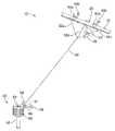
도 1은 예시적인 실시예에 따른, 전기 도전성 끈(30)을 사용하여 지상국(50)에 부착된 항공기(20)를 포함하는 공중 풍력 터빈(10)의 사시도이다.
도 2는 도 1에 도시된 항공기(20)의 확대 사시도이다.
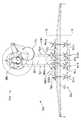
도 3은 예시적인 실시예에 따른, 지상국(150)에 부착된 퍼치 패널(160)에 앉아 있는 항공기(120)의 측면도이다.
도 4는 예시적인 실시예에 따른, 도 3에 도시된 항공기(120) 및 지상국(150)의 평면도이다.
도 5는 예시적인 실시예에 따른, 비행 제어 유닛들(210 및 212)과 전력 발생 터빈들(140a-g)과의 배선을 도시하는, 도 3 및 도 4에 도시된 항공기(120)의 배선도이다.
도 6은 예시적인 실시예에 따른, 비행 제어 유닛들(210 및 212)과 보조 날개, 후방 엘리베이터 및 방향타 서보 모터들과의 배선을 도시하는, 도 3 및 도 4에 도시된 항공기(120)의 배선도이다.
도 7은 예시적인 실시예에 따른, 도 3 및 도 4에 도시된 항공기(120)에서 사용될 수 있는 통신 링크를 나타내는 개략 표현이다.
도 8은 도 3 및 도 4에 도시된 항공기(120)의 네트워크의 구성 요소들 사이의 통신 링크들을 나타내는 블록도이다.1 is a perspective view of an
2 is an enlarged perspective view of the
3 is a side view of an
4 is a plan view of the
5 is a schematic diagram of the
FIG. 6 is a side elevational view of the
FIG. 7 is a schematic representation of a communication link that may be used in the
8 is a block diagram illustrating communication links between components of the network of
예시적인 방법들 및 시스템들이 본 명세서에서 설명된다. 본 명세서에서 설명된 임의의 예시적인 실시예 또는 특징은 반드시 다른 실시예들 또는 특징들보다 선호되거나 유리한 것으로 해석되어서는 안 된다. 본 명세서에서 설명된 예시적인 실시예들은 제한하려는 것이 아니다. 개시된 시스템들 및 방법들의 특정 양태들은 본 명세서에서 모두 고려되는 다양한 상이한 구성들로 배열되고 조합될 수 있음을 쉽게 이해할 것이다.Exemplary methods and systems are described herein. Any illustrative embodiment or feature described herein should not necessarily be construed as preferred or advantageous over other embodiments or features. The exemplary embodiments described herein are not intended to be limiting. It will be readily understood that the specific aspects of the disclosed systems and methods can be arranged and combined in a variety of different configurations, all of which are contemplated herein.
또한, 도면들에 도시된 특정 구성들은 제한적인 것으로 간주되어서는 안 된다. 다른 실시예들은 주어진 도면에 도시된 각각의 요소를 더 많이 또는 더 적게 포함할 수 있음을 이해해야 한다. 또한, 도시된 요소들 중 일부는 결합되거나 생략될 수 있다. 또한, 예시적인 실시예는 도면들에 도시되지 않은 요소들을 포함할 수 있다.In addition, the specific configurations shown in the drawings are not to be considered limiting. It is to be understood that other embodiments may include more or less of each element shown in the figures. In addition, some of the elements shown may be combined or omitted. Further, the exemplary embodiment may include elements not shown in the figures.
1.개요One.summary
예시적인 실시예들은 공중 풍력 터빈(AWT)과 같은 풍력 에너지 시스템에서 사용될 수 있는 항공기에 관한 것이다. 특히, 예시적인 실시예들은 전기 도전성 끈을 사용하여 지상국에 부착되는 항공기를 이용하는 방법들 및 시스템들에 관련되거나 그 형태를 취할 수 있다.Exemplary embodiments relate to aircraft that can be used in wind energy systems, such as an aerial wind turbine (AWT). In particular, exemplary embodiments may relate to or take the form of methods and systems using an aircraft that is attached to a ground station using an electrically conductive string.
풍력 에너지를 전기 에너지로 변환하기 위해 AWT와 같은 풍력 에너지 시스템이 사용될 수 있다. AWT는 터빈들이 장착된 강성 날개로 구성된 항공기를 포함할 수 있는 풍력 기반의 에너지 생성 장치이다. 항공기는 운동 에너지를 전기 에너지로 변환하기 위해 지면(또는 수면) 위에 실질적으로 원형 경로와 같이 바람을 가로지르는 경로에서 비행하도록 작동할 수 있다. 이러한 측풍 비행(cross wind flight)에서, 항공기는 풍력 터빈의 팁(tip)과 유사한 원형 패턴으로 바람을 가로질러 비행한다. 강성 날개에 부착된 회전자(rotor)들은 날개를 감속시킴으로써 전력을 생성하는 데 사용될 수 있다. 특히, 터빈 블레이드들을 가로질러 움직이는 공기는 블레이드들을 강제로 회전시켜, 발전기를 구동하여 전기를 생성할 수 있다. 항공기는 또한 항공기에 의해 생성된 전력을 지상국으로, 그리고 그리드로 전송하는 전기 도전성 끈을 통해 지상국에 연결될 수 있다.Wind energy systems such as AWT can be used to convert wind energy into electrical energy. AWT is a wind-based energy generation device that can include aircraft composed of rigid wings equipped with turbines. The aircraft can operate to fly in a path across the wind, such as a substantially circular path, on the ground (or surface) to convert kinetic energy into electrical energy. In this cross wind flight, the aircraft flies across the wind in a circular pattern similar to the tip of the wind turbine. Rotors attached to a rigid wing can be used to generate power by decelerating the wing. In particular, air moving across the turbine blades can force the blades to rotate, driving the generator to generate electricity. The aircraft can also be connected to the ground station via an electrically conductive strap that transfers power generated by the aircraft to ground stations and to the grid.
항공기를 착륙시키기를 원할 때, 전기 도전성 끈은 지상국의 스풀 또는 드럼 상에 감기고, 항공기는 지상국의 퍼치 쪽으로 당겨진다. 퍼치에 착륙하기 전에, 항공기는 비행 모드에서 호버 모드로 전환한다. 항공기가 퍼치에 얹혀질 때까지 드럼에 끈을 더 감도록 드럼이 더 회전된다.When it is desired to land the aircraft, the electrically conductive string is wound on the spool or drum of the ground station, and the aircraft is pulled toward the perch of the ground station. Before landing on a perch, the aircraft switches from flight mode to hover mode. The drum is further rotated to wind the drum further on the drum until the aircraft rests on the perch.
항공기는 전기를 발생시킬 때 공중에서 상당한 시간을 소비할 수 있다. 그러나, 그 기간 동안 항공기는 낙뢰 및 다른 형태의 전자기 간섭("EMI")의 영향을 받기 쉽다. 그러므로, 모터 및 번개로부터의 고전압 모터/터빈 시스템과 EMI 양쪽 모두로부터 항공기의 온보드의 통신 네트워크의 전기 절연을 제공하는 것이 바람직하다.Airplanes can consume considerable time in the air when generating electricity. However, during that period, aircraft are susceptible to lightning and other forms of electromagnetic interference ("EMI"). Therefore, it is desirable to provide electrical isolation of the onboard communication network of the aircraft from both the high voltage motor / turbine system and the EMI from the motor and lightning.
통신 네트워크에서 구리 와이어와 같은 전기 도전성 매체를 사용하는 것의 하나의 대안은 긴 고대역폭 링크들에, 예를 들어, 도시들 또는 캠퍼스의 건물들을 연결하기 위해 사용될 수 있는 광섬유를 사용하는 것이다. 이러한 유형의 섬유는 유리로 만들어지며, 일반적인 코어 직경은 9, 50 및 62.5미크론이다. 유리 광섬유 기술은 커플러, 센서 및 트랜스듀서에 인터페이스하는 유리 표면의 양호한 기계적 정밀도와 양질의 광학적 마감을 갖는 커넥터를 필요로 한다.One alternative to using electrically conductive media such as copper wires in communication networks is to use optical fibers that can be used to connect long high bandwidth links, for example, cities or campus buildings. This type of fiber is made of glass, with typical core diameters of 9, 50 and 62.5 microns. Glass fiber optic technology requires connectors with good mechanical precision and good optical finish on glass surfaces that interface to couplers, sensors and transducers.
번개 또는 다른 소스로부터의 EMI에 대해 원하는 전기 절연 및 감소된 민감성을 제공하기 위해, 항공 상업용 및 군용 응용들에서 통상적으로 유리 광섬유가 사용된다. 그러나, 유리 섬유 링크를 설치하고 정비하는 데에는 일반적으로 특수한 설정들에서만 얻을 수 있는 청결도가 또한 요구된다. 또한, 유리 섬유 기술이 항공 상업용 또는 군용 응용들에서 사용되는 경우, 진동, 습기 및 잔해로 특징지어지는 동작 환경을 지원하는 데 필요한 광섬유 커넥터 기술은 매우 비용이 많이 드는데, 그 이유는 이러한 커넥터들은 각각 비용이 $400 내지 $1000 정도 들기 때문이다.Glass optical fibers are typically used in aviation commercial and military applications to provide the desired electrical isolation and reduced sensitivity to EMI from lightning or other sources. However, the installation and maintenance of fiberglass links also generally requires cleanliness that can only be achieved with special settings. Also, when fiberglass technology is used in aviation commercial or military applications, the fiber optic connector technology required to support an operating environment characterized by vibration, moisture, and debris is very costly, It costs $ 400 to $ 1000.
AWT 상에 20개 이상의 광 링크가 있을 수 있다고 가정하면, 온보드의 다중 모드 유리 섬유를 지원하는 비용은 엄청나게 비싸다. 또한, 유리 광섬유의 작은 직경들을 고려할 때, 연결 지점의 작은 먼지 입자조차 광섬유가 신호 송신기로서 기능하지 못하게 할 수 있다. 따라서 AWT의 통신 시스템에 기존의 유리 광섬유 기술을 사용하는 것은 항공기가 진동, 습기, 바람 및 잔해로 특징지어지는 가혹한 동작 조건의 적용을 받는 현장에서 항공기를 정비하고 유지 보수하는 것의 어려움을 고려할 때 매우 비용이 많이 든다.Assuming that there may be more than 20 optical links on the AWT, the cost of supporting on-board multimode fiberglass is prohibitively high. Also, considering the small diameters of the glass optical fibers, even small dust particles at the splice point can render the fiber not function as a signal transmitter. Therefore, the use of conventional glass fiber optic technology in AWT's communications systems is very difficult when considering the difficulty of servicing and maintaining the aircraft in the field, where the aircraft is subjected to harsh operating conditions characterized by vibration, moisture, wind and debris It costs a lot.
따라서, 원하는 전기 절연을 제공할 수 있으면서도, 신호 전송 매체가 더 쉽게 절단되고, 종단되고, 연결될 수 있는 현장에서 정비 가능하고, 먼지 또는 잔해가 수반되는 가혹한 동작 조건들에서도 신뢰성 있게 동작할 수 있는 온보드 통신 시스템을 제공한다면 바람직할 것이다.Thus, it is possible to provide an onboard < RTI ID = 0.0 > onboard < / RTI > circuit that is capable of providing desired electrical isolation while being reliably operable even in harsh operating conditions where the signal transmission medium can be easily cut, terminated, It would be desirable to provide a communication system.
예시적인 실시예에서, 때로는 폴리머 광섬유라고도 불리는 플라스틱 광섬유(POF)가 전기 도체 또는 유리 광섬유 대신에 항공기 온보드의 신호를 전송하는 데 사용된다. 항공기 네트워크상의 통신 링크 매체로서의 POF는 고전압 모터/터빈 시스템과 비행 컴퓨터 사이의 갈바니 절연을 제공한다. 플라스틱 광섬유는 또한 모터 및 번개로부터의 전자기 간섭에 대한 민감성을 감소시킨다. POF는 불소 중합체 재킷으로 피복될 수 있는 초순수 폴리메틸메타크릴레이트(PMMA) 섬유 코어로 제조될 수 있다. 중요하게는, POF는 약 1mm의 큰 코어 직경을 가질 수 있다. 이와 비교하여, 다중 모드 유리 섬유는 62.5미크론의 코어 직경을 갖는다. POF의 비교적 큰 직경의 코어는 수신기 및 송신기 전자 회로들과의 보다 용이한 결합을 가능하게 하고 산업 환경에서 사용하기에 적합한 저비용 커넥터 시스템들의 사용을 가능하게 한다.In an exemplary embodiment, a plastic optical fiber (POF), sometimes referred to as a polymer optical fiber, is used to transmit the aircraft's onboard signal instead of an electrical conductor or glass optical fiber. POF as a communication link medium on an aircraft network provides galvanic isolation between a high voltage motor / turbine system and a flight computer. Plastic optical fibers also reduce sensitivity to electromagnetic interference from motors and lightning. POF can be made of ultra-pure water polymethyl methacrylate (PMMA) fiber cores which can be coated with a fluoropolymer jacket. Importantly, the POF can have a large core diameter of about 1 mm. In comparison, the multimode glass fibers have a core diameter of 62.5 microns. The relatively large diameter core of POF allows for easier coupling with receiver and transmitter electronics and enables the use of low cost connector systems suitable for use in industrial environments.
유리 섬유에 비해 POF를 사용하는 것의 주된 단점은 증가된 에너지 흡수 및 증가된 모드 분산이다. 기본적인 POF 섬유 감쇠 또는 광학 손실은 650nm LED 송신기와 함께 사용되는 경우 일반적으로 160dB/km 내지 300dB/km의 범위에서 지정된다. 이와 비교하여, 다중 모드 유리 섬유의 손실은 일반적으로 겨우 약 .3dB/km 내지 10dB/km에서 지정된다. 높은 감쇠는 POF 링크의 길이를 일반적으로 50미터 이하로 제한한다. 또한, 표준 저비용 POF 섬유는 펄스 분산을 증가시키는 경사형 인덱스(gradient index)가 아니라, 계단형 인덱스(step-index)를 갖는다. 증가된 코어 직경은 섬유가 LED 송신기로부터 더 많은 광을 모을 수 있게 하지만, 증가된 개구수는 펄스 분산도 증가시킨다. 펄스 분산은 신호 대역폭을 고속 이더넷 속도로 제한한다. 이러한 단점과 다중 모드 유리 광섬유의 오래된 사용으로 인해 다중 모드 유리 광섬유가 상업용 또는 군용 항공 응용들에서 널리 사용된다.The main disadvantages of using POF over fiberglass are increased energy absorption and increased mode dispersion. Basic POF fiber attenuation or optical loss is typically specified in the range of 160dB / km to 300dB / km when used with a 650nm LED transmitter. In comparison, the loss of multimode glass fibers is typically specified at only .3 dB / km to 10 dB / km. High attenuation limits the length of the POF link to generally 50 meters or less. In addition, standard low cost POF fibers have a step-index instead of a gradient index that increases pulse dispersion. The increased core diameter allows the fiber to collect more light from the LED transmitter, but the increased numerical aperture also increases the pulse dispersion. Pulse dispersion limits the signal bandwidth to high-speed Ethernet speeds. Due to these shortcomings and the old use of multimode glass optical fibers, multimode glass optical fibers are widely used in commercial or military aviation applications.
그러나, AWT에 사용되는 전형적인 항공기는 종래의 상업용 및 군용 항공기보다 훨씬 작다. 그러므로, POF를 사용할 때 고도의 감쇠 또는 광학 손실의 단점에도 불구하고, 광학 연결들 간의 거리가 비교적 짧기 때문에, POF의 사용은 AWT 항공기 내의 신호 전송에 적합하다. 특히, 중앙에 위치한 비행 제어기 유닛들, 또는 비행 컴퓨터들과 가장 멀리 떨어져 있는 보조 날개 간의 거리는 10미터 미만일 수 있고, 각각의 보조 날개들 간의 거리는 3.5미터 정도일 수 있다. 또한, 비행 제어기 유닛(Flight Controller Unit, FCU)들과 터빈/모터들 간의 거리도 대략 6미터 이하일 수 있고, FCU들과 방향타들 및 후방 날개들(또는 엘리베이터들) 간의 거리도 길이가 10미터 미만일 수 있다. 그러므로, POF의 사용은 AWT의 항공기상의 이러한 제한된 거리에 적합하다.However, the typical aircraft used in AWT is much smaller than conventional commercial and military aircraft. Therefore, despite the disadvantages of high attenuation or optical loss when using POF, the use of POF is suitable for signal transmission within AWT aircraft, because the distance between optical connections is relatively short. In particular, the distance between the centrally located flight control units or the flight computers and the furthest furthest away from each other may be less than 10 meters, and the distance between the respective furthings may be about 3.5 meters. Also, the distance between the Flight Controller Unit (FCU) and the turbine / motors may be less than about 6 meters, and the distance between the FCUs and the rudders and rear wings (or elevators) may be less than 10 meters . Therefore, the use of POF is appropriate for this limited distance on AWT's aircraft.
POF는 항공기상에서 요구되는 제한된 거리에 대한 신호 전송에 적합할 뿐만 아니라, POF의 사용은 전기 도체 또는 다중 모드 유리 광섬유에 비해 상당한 이점들을 제공한다. 특히, POF는 구리보다 가볍고, 신뢰성 있고, 정비 가능하며, 원하는 전기 절연을 제공한다.Not only is POF suitable for signal transmission over a limited range of distances required on aircraft, the use of POF provides significant advantages over electrical conductors or multimode glass optical fibers. In particular, POF is lighter, more reliable, more maintainable than copper, and offers the desired electrical insulation.
상술한 바와 같이, POF의 코어는 약 1mm의 직경을 가질 수 있는 반면, 다중 모드 유리 광섬유의 코어는 62.5미크론의 직경을 갖는다. 그 결과, POF 코어의 연결 면적은 유리 섬유 코어의 연결 면적보다 250배 이상 더 크다. 그 결과, POF 코어는 미크론 크기의 먼지와 잔해에 비교적 영향을 받지 않는다. 예를 들어, 유리 섬유들 간의 통신을 신뢰할 수 없게 만드는 연결 지점의 잔해 조각은 POF 섬유의 훨씬 큰 연결 표면적을 고려할 때 POF 섬유 간의 연결 지점에 영향을 주지 않을 수 있다. POF 섬유가 제공하는 잔해와 스크래치에 대해 동일한 내성을 확보하기 위해서는, 커넥터의 청소가 옵션이 아닌 경우 값비싼 확장된 빔 커넥터가 요구되며, 이는 전형적인 POF 커넥터와 비교하여 비용을 크게 증가시킨다.As described above, the core of the POF may have a diameter of about 1 mm, while the core of the multimode glass optical fiber has a diameter of 62.5 microns. As a result, the connection area of the POF core is more than 250 times larger than the connection area of the glass fiber core. As a result, the POF core is relatively unaffected by micron-sized dust and debris. For example, debris fragments at junctions that make communications between glass fibers unreliable may not affect the junctions between POF fibers, considering the much larger surface area of connection of POF fibers. In order to ensure the same immunity to scratches and debris provided by POF fibers, expensive cleaning of the connector is not an option and expensive extended beam connectors are required, which significantly increases costs compared to typical POF connectors.
또한, POF를 사용하는 경우 연결 지점에서의 표면적이 비교적 훨씬 더 크기 때문에, POF는 절단/결합이 훨씬 더 용이하고, 유리 섬유를 사용할 경우 용인될 수 없는 정도의 오정렬을 허용하여 정렬이 더 용이하고, 먼지와 잔해가 존재하는 경우 가혹한 환경에 훨씬 더 내성이 있다. 따라서, 신호 전송을 위한 POF의 사용은 유리하게도 통신 시스템에 대한 증가된 신뢰성을 제공한다.Also, with POF, the surface area at the connection points is relatively much larger, so the POF is much easier to cut and join and allows for misalignment that is unacceptable when using glass fibers, , And are more resistant to harsh environments when dust and debris are present. Thus, the use of POF for signal transmission advantageously provides increased reliability for the communication system.
항공기상에 배치된 통신 네트워크는 또한 유리하게 신뢰성 있는 동작을 보장하기 위해 다수의 중복성(redundancy)을 포함할 수 있다. 특히, 사용되는 비행 제어 컴퓨터가 2개 존재할 수 있다. 신호를 송수신하기 위한 듀플렉스 POF 전송 라인은 각각의 비행 제어 컴퓨터와 전력 발생 터빈들 각각의 사이에 연장될 수 있다. 듀플렉스 POF 전송 라인은 2개의 심플렉스 섬유(simplex fiber)로 구성될 수 있으며, 이들은 집코드 웹(zipcord web)으로 결합될 수 있다. 추가적인 중복성을 위해 제3 비행 제어 컴퓨터가 사용될 수도 있다.Communications networks deployed on an aircraft may also include a number of redundancies to advantageously ensure reliable operation. In particular, there may be two flight control computers used. A duplex POF transmission line for transmitting and receiving signals may be extended between each flight control computer and each of the power generation turbines. Duplex POF transmission lines can be composed of two simplex fibers, which can be combined into a zipcord web. A third flight control computer may be used for additional redundancy.
유사하게, 듀플렉스 POF 전송 라인들은 각각의 비행 제어 컴퓨터와 보조 날개들, 방향타들 및 후방 엘리베이터들 각각의 사이에도 연장될 수 있다. 하나의 링크가 고장나면, 다른 비행 제어기로부터 사용될 수 있는 중복 라인이 있다. 따라서, 시스템은 POF 전송 라인들의 내장 중복성 및 사용에 기초하여 증가된 신뢰도를 갖는다.Similarly, duplex POF transmission lines may extend between each flight control computer and each of the auxiliary vanes, rudders, and rear elevators. If one link fails, there are redundant lines that can be used from other flight controllers. Thus, the system has increased reliability based on the built-in redundancy and use of POF transmission lines.
2.예시적인 공중 풍력 터빈들2.Exemplary aerial wind turbines
도 1 및 도 2에 개시된 바와 같이, 예시적인 실시예에 따른 공중 풍력 터빈(AWT)(10)이 개시된다. AWT(10)는 바람을 가로질러, 실질적으로 원형 경로와 같은 경로에서 비행하는, 터빈들(40)이 장착된 강성 날개(22)로 구성되는 항공기(20)를 포함하는 풍력 기반의 에너지 생성 장치이다. 예시적인 실시예에서, 항공기는 운동 풍력 에너지를 전기 에너지로 변환하기 위해 지면(또는 수면) 위에 250미터와 600미터 사이에서 비행할 수 있다. 그러나, 항공기는 본 발명의 범위에서 벗어나지 않고 다른 높이들에서 비행할 수 있다. 측풍 비행에서, 항공기(20)는 풍력 터빈의 팁과 유사한 원형 패턴으로 바람을 가로질러 비행한다. 강성 날개(22)에 부착되는 회전자들(40)은 날개(22)를 감속시킴으로써 전력을 생성하는 데 이용된다. 터빈 블레이드들을 가로질러 움직이는 공기는 블레이드들을 강제로 회전시켜, 발전기를 구동하여 전기를 생성할 수 있다. 항공기(20)는 항공기에 의해 생성된 전력을 지상국(50)으로, 그리고 그리드로 전송하는 전기 도전성 끈(30)을 통해 지상국(50)에 연결된다.As disclosed in Figures 1 and 2, an airwave turbine (AWT) 10 in accordance with an exemplary embodiment is disclosed. The
도 1에 도시된 바와 같이, 항공기(20)는 끈(30)에 연결될 수 있고, 끈(30)은 지상국(50)에 연결될 수 있다. 이 예에서, 끈(30)은 지상국(50) 상의 한 위치에서 지상국(50)에 부착되고, 브라이들(32a, 32b, 및 32c)을 사용하여 항공기(20)상의 3개 위치에서 항공기(20)에 부착될 수 있다. 그러나 다른 예들에서, 끈(30)은 다수의 위치에서 지상국(50) 및/또는 항공기(20) 중 임의의 부분에 부착될 수 있다.1, the
지상국(50)은 그것이 동작 모드에 있을 때까지 항공기(20)를 잡고 그리고/또는 지지하기 위해 사용될 수 있다. 지상국은 대략 15미터의 높이일 수 있는 탑(52)을 포함할 수 있다. 지상국은 끈(30)을 회전 가능한 드럼(52) 상으로 감음으로써 항공기(20)를 당기는 데 사용되는 드럼 축(53)을 중심으로 회전 가능한 드럼(52)을 또한 포함할 수 있다. 이 예에서, 드럼(52)은 수직으로 배향되지만, 드럼은 또한 수평으로(또는 경사지게) 배향될 수도 있다. 또한, 지상국(50)은 착륙 동안 항공기(20)를 수용하도록 추가로 구성될 수 있다. 예를 들어, 지지 부재(56)가 지상국(50)으로부터 연장되는 퍼치 패널들(58)에 부착된다. 끈(30)이 드럼(52) 상에 감기고, 항공기(20)가 지상국(50) 쪽으로 당겨질 때, 항공기는 퍼치 패널들(58)에 얹혀질 수 있다. 지상국(50)은 호버 비행, 전방 비행 또는 측풍 비행 동안 항공기(20)를 적절히 지상국에 부착되고/부착되거나 고정되게 유지할 수 있는 임의의 재료로 형성될 수 있다. 일부 구현들에서, 지상국(50)은 착륙시 사용을 위해 구성될 수 있다. 그러나 지상국(50)은 또한 호수, 강, 바다, 또는 대양과 같은 수역에 구현될 수도 있다. 예를 들어, 지상국은, 여러 가능성들 중에서도, 부동 해상 플랫폼(floating off-shore platform) 또는 보트를 포함하거나 이들 상에서 배열될 수 있다. 또한, 지상국(50)은 지면 또는 수역의 표면에 대해 고정되거나 이동하도록 구성될 수 있다.The
끈(30)은 항공기(20)에 의해 생성된 전기 에너지를 지상국(50)에 전송할 수 있다. 또한, 끈(30)은 이륙, 착륙, 호버 비행 및/또는 전방 비행 동안 항공기(20)에 전력을 공급하기 위해 항공기(20)에 전기를 전송할 수 있다. 끈(30)은 항공기(20)에 의해 생성된 전기 에너지의 전송, 전달 및/또는 활용 및/또는 항공기(20)로의 전기의 전송을 허용할 수 있는 임의의 재료를 사용하여 그리고 임의의 형태로 구성될 수 있다. 끈(30)은 항공기(20)가 동작 모드에 있을 때 항공기(20)의 하나 이상의 힘을 견디도록 또한 구성될 수 있다. 예를 들어, 끈(30)은 항공기(20)가 호버 비행, 전방 비행 및/또는 측풍 비행에 있을 때 항공기(20)의 하나 이상의 힘을 견디도록 구성되는 코어를 포함할 수 있다. 코어는 임의의 높은 강도의 섬유들 또는 탄소 섬유 로드(carbon fiber rod)로 구성될 수 있다. 일부 예들에서, 끈(30)은 고정 길이 및/또는 가변 길이를 가질 수 있다. 예를 들어, 일 예에서, 끈은 500미터의 고정 길이를 가진다.The
항공기(20)는 여러 가능성들 중에서도, 연, 헬기, 날개 및/또는 비행기와 같은 다양한 유형의 장치를 포함하거나 그의 형태를 취할 수 있다. 항공기(20)는 금속, 플라스틱 및/또는 다른 폴리머들의 고체 구조들로 형성될 수 있다. 항공기(20)는 유틸리티 응용들에서 사용될 수 있는 전기 에너지의 생성 및 높은 추력-대-중량 비를 허용하는 임의의 재료로 형성될 수 있다. 또한, 재료들은 풍속 및 풍향에서 커다란 그리고/또는 급격한 변화들을 다룰 수 있는, 번개 강화된(lightning hardened), 중복 및/또는 고장 내성의 설계를 허용하도록 선택될 수 있다. 다른 재료들도 가능할 수 있다.The
도 1에 도시된 바와 같이, 그리고 도 2에서 더 상세히 도시된 바와 같이, 항공기(20)는 주 날개(22), 회전자들(40a 및 40b), 꼬리 부리(tail boom) 또는 동체(24), 및 테일 날개(26)를 포함할 수 있다. 이러한 구성 요소들 중 임의의 것은 중력에 저항하고 그리고/또는 항공기(20)를 전방으로 이동시키기 위한 양력의 구성 요소들의 사용을 허용하는 임의의 형태로 성형될 수 있다.As shown in Figure 1 and as shown in more detail in Figure 2, the
주 날개(22)는 항공기(20)에 대한 주된 양력을 제공할 수 있다. 주 날개(22)는 하나 이상의 강성 또는 연성 에어포일일 수 있으며, 윙릿(winglets), 플랩(flaps), 방향타, 엘리베이터 등과 같은 다양한 제어 표면들을 포함할 수 있다. 제어 표면들은 항공기(20)를 안정시키고 그리고/또는 호버 비행, 전방 비행 및/또는 측풍 비행 동안 항공기(20)상의 항력을 감소시키는 데 이용될 수 있다. 주 날개(22)는 항공기(20)가 호버 비행, 전방 비행 및/또는 측풍 비행에 관여하기 위한 임의의 적절한 재료일 수 있다. 예를 들어, 주 날개(22)는 탄소 섬유 및/또는 e-글라스를 포함할 수 있다.The
회전자 커넥터들(43)은 상부 회전자들(40a)을 주 날개(22)에 연결하기 위해 사용될 수 있고, 회전자 커넥터들(41)은 하부 회전자들(40b)을 주 날개(22)에 연결하기 위해 사용될 수 있다. 일부 예들에서, 회전자 커넥터들(43 및 41)은 하나 이상의 파일론의 형태를 취할 수 있거나 그와 형태가 유사할 수 있다. 이 예에서, 회전자 커넥터들(43 및 41)은 상부 회전자들(40a)이 날개(22)의 위에 배치되고 하부 회전자들(40b)가 날개(22)의 아래에 배치되도록 배열된다.
회전자들(40a 및 40b)은 전기 에너지를 생성할 목적으로 하나 이상의 발전기를 구동하도록 구성될 수 있다. 이 예에서, 회전자들(40a 및 40b)은 각각 3개의 블레이드와 같은 하나 이상의 블레이드(45)를 포함할 수 있다. 하나 이상의 회전자 블레이드(45)는 바람과의 상호작용을 통해 회전할 수 있으며, 이는 하나 이상의 발전기를 구동하는 데 사용될 수 있다. 또한, 회전자들(40a 및 40b)은 비행 중인 항공기(20)에 추력을 제공하도록 구성될 수도 있다. 이 배열을 이용하여, 회전자들(40a 및 40b)은 프로펠러와 같은 하나 이상의 추진 유닛으로서 기능할 수 있다. 회전자들(40a 및 40b)은 이 예에서 4개의 회전자로서 도시되지만, 다른 예들에서, 항공기(20)는, 4개 미만의 회전자 또는 4개 초과의 회전자, 예를 들어, 6개 또는 8개 회전자와 같은, 임의의 개수의 회전자들을 포함할 수 있다.The
도 1을 다시 참조하면, 항공기(20)를 착륙시키기를 원할 때, 드럼(52)은 항공기(20)를 지상국(50)의 퍼치 패널들(58) 쪽으로 당기도록 회전되며, 전기 도전성 끈(30)은 드럼(52) 상에 감긴다. 퍼치 패널들(58)에 착륙하기 이전에, 항공기(20)는 비행 모드에서 호버 모드로 전환한다. 항공기(20)가 퍼치 패널들(58)에 얹혀질 때까지 드럼(52)이 추가로 회전되어 끈(30)을 드럼(52) 상에 추가로 감는다.1, when it is desired to land the
도 3은 지상국(150)에 부착된 퍼치 패널(160)에 앉아 있는 항공기(120)을 포함하는 공중 풍력 터빈의 측면도이고, 도 4는 예시적인 실시예에 따른, 도 3에 도시된 항공기(120) 및 지상국(150)의 평면도이다. 도 3 및 도 4에서, 지상국(150)은 회전 가능한 드럼(180) 및 레벨윈드(levelwind)(182)가 위에 배치되는 탑(152)을 포함한다. 일 실시예에서, 탑(152)은 높이가 15미터일 수 있다. 전기 도전성 끈(130)이 레벨윈드로부터 연장되고 브라이들 라인들(132a, 132b 및 132c)을 사용하여 항공기(120)의 날개(122)에 부착된다. 일 실시예에서, 브라이들 라인들(132a, 132b 및 132c)은 날개(122)의 폭(span)을 따라 비대칭 위치들에 부착됨으로써, 날개(122)의 동체 안쪽은 날개 끝으로부터 더 멀리 부착된 브라이들을 갖고 날개(122)의 동체 바깥쪽은 동체 바깥쪽 날개 끝에 더 가까이 부착된 브라이들을 갖는다. 이러한 비대칭 구성은 브라이들 라인들(132a 및 132c)이 더 큰 크기의 퍼치 패널에 더 양호하게 닿지 않고 지나가게 한다.Figure 3 is a side view of an aerial wind turbine including an
퍼치 패널(160)은 지상국(150)에 배치된 퍼치 플랫폼(172)으로부터 수평으로 연장되는 퍼치 패널 지지 부재들(170a 및 170b)에 의해 지지된다. 퍼치 패널 플랫폼(172)은 항공기(120)가 착륙하고 있을 때 퍼치 패널(160)이 적절한 위치에 있도록 탑(52) 의 꼭대기 주위로 회전할 수 있다. 항공기(120)는 날개(122)에 부착된 파일론(143) 상에 장착된 하부 회전자들(140a) 및 프로펠러(145)를 갖는 날개에 부착된 파일론(143) 상에 장착된 상부 회전자들(140b)을 포함한다. 회전자들(140a 및 140b)은 전력 발생 터빈들에 도움이 될 수 있다. 일 실시예에서, 날개(122)는 4미터 길이이다. 항공기는 페그(peg)(28)가 부착되는 만곡부(129)를 갖는 동체(124)를 포함한다. 앉아 있는 상태에서, 도 3 및 도 4에 도시된 바와 같이, 페그(28)는 제1면(160a) 및 제2면(160b)으로 구성된 퍼치 패널(160)에 접촉한다.The
또한, 항공기(120)가 착륙하는 동안 호버 모드에 있을 때, 페그(128)는 동체(124)로부터 퍼치 패널(160)을 향하여 아래쪽으로 그리고 바깥쪽으로 연장된다. 도 4에 도시된 바와 같이, 퍼치 패널(160)은 레벨윈드(182)를 통하여 지상국(150)상의 축(184)을 중심으로 회전하는 회전 가능한 드럼(180) 상으로 유도되는 끈(130)과 정렬될 수 있다. 이러한 방식으로, 퍼치 패널(160)은 착륙할 때 항공기(120)의 동체(124)를 마주본다. 도 3 및 도 4에 도시된 드럼(180)은 수직 회전축(184)을 갖는다. 그러나, 수평 드럼 또는 경사진 드럼이 사용될 수도 있다. 예를 들어, 수평축을 중심으로 회전 가능한 드럼이 사용되는 경우, 퍼치 플랫폼(172)은 퍼치 플랫폼(172)이 드럼의 축으로부터 수직으로 연장되고 끈(130)이 퍼치 패널(160) 위의 드럼 상에 감기도록 드럼에 결합될 수 있다. 이러한 방식으로 끈(130)이 드럼 상에 감길 때, 퍼치 패널(130)은 항상 항공기(120)를 마주보고 항공기(120)의 동체(124)상의 페그(128)를 수용하기 위해 적소에 있을 것이다. 사실, 드럼은 끈(130)(또는 중앙 끈 브라이들(132b))이 퍼치 패널(160)의 홈(164)의 바닥 위로 연장되도록 퍼치 플랫폼(172) 상에 배치될 수 있다.In addition, when the
3.내장 중복성을 갖는 POF 통신 시스템3.POF communication system with built-in redundancy
도 5는 비행 제어 유닛들(210 및 212)과 회전자들(140a-140h)의 배선을 도시하는, 도 3 및 도 4에 도시된 항공기(120)의 배선도이다. 특히, 듀플렉스 플라스틱 광섬유가 비행 제어 유닛들(210 및 212)과 전력 발생 터빈들(140a-140h) 사이의 신호 전송 매체로서 사용된다. 듀플렉스 플라스틱 광섬유는 신호를 전송하기 위한 하나의 라인과 신호를 수신하기 위한 하나의 라인을 제공함으로써 구성 요소들 간의 양방향 통신을 가능하게 한다. 또한, 후술하는 바와 같이, 공중 풍력 터빈(100)상의 통신 네트워크에 대한 증가된 신뢰성을 제공하기 위해 시스템에 중복성이 유리하게 통합된다.5 is a wiring diagram of the
도 5에 도시된 바와 같이, 항공기(120)는 회전자들(140a-140g)이 부착되는 주 날개(122)을 포함한다. 회전자들(140a-140h)은 예를 들어 퍼치로부터 이륙하는 동안 추력 발생기들의 역할을 할 수 있고, 또한 항공기가 정상 비행 모드에서 동작할 때 전력 발생 터빈들의 역할을 할 수 있다. 고도의 시스템 신뢰성을 제공하기 위해, 제1 비행 제어 유닛(210)은 듀플렉스 플라스틱 광섬유를 사용하여 회전자들(140a-140h) 각각으로의 통신 링크를 제공한다.As shown in FIG. 5, the
특히, 듀플렉스 플라스틱 광섬유(240a)가 제1 비행 제어 유닛(210)과 회전자(140a) 사이에 연장되고, 듀플렉스 플라스틱 광섬유(240b)가 제1 비행 제어 유닛(210)과 회전자(140b) 사이에 연장되고, 듀플렉스 플라스틱 광섬유(240c)가 제1 비행 제어 유닛(210)과 회전자(140c) 사이에 연장되고, 듀플렉스 플라스틱 광섬유(240d)가 제1 비행 제어 유닛(210)과 회전자(140d) 사이에 연장되고, 듀플렉스 플라스틱 광섬유(240e)가 제1 비행 제어 유닛(210)과 회전자(140e) 사이에 연장되고, 듀플렉스 플라스틱 광섬유(240f)가 제1 비행 제어 유닛(210)과 회전자(140f) 사이에 연장되고, 듀플렉스 플라스틱 광섬유(240g)가 제1 비행 제어 유닛(210)과 회전자(140g) 사이에 연장되고, 듀플렉스 플라스틱 광섬유(240h)가 제1 비행 제어 유닛(210)과 회전자(140h) 사이에 연장된다.In particular, a duplex plastic
신뢰성 있는 신호 전송은 또한 중복 제2 비행 제어 유닛(212)의 사용을 수반한다. 고도의 시스템 신뢰성을 제공하기 위해, 제2 비행 제어 유닛(212)도 신호 전송을 위한 듀플렉스 플라스틱 광섬유를 사용하여 회전자들(140a-140h) 각각으로의 통신 링크를 제공한다.Reliable signal transmission also involves the use of redundant second
특히, 듀플렉스 플라스틱 광섬유(250a)가 제1 비행 제어 유닛(210)과 회전자(140a) 사이에 연장되고, 듀플렉스 플라스틱 광섬유(250b)가 제1 비행 제어 유닛(210)과 회전자(140b) 사이에 연장되고, 듀플렉스 플라스틱 광섬유(250c)가 제1 비행 제어 유닛(210)과 회전자(140c) 사이에 연장되고, 듀플렉스 플라스틱 광섬유(250d)가 제1 비행 제어 유닛(210)과 회전자(140d) 사이에 연장되고, 듀플렉스 플라스틱 광섬유(250e)가 제1 비행 제어 유닛(210)과 회전자(140e) 사이에 연장되고, 듀플렉스 플라스틱 광섬유(250f)가 제1 비행 제어 유닛(210)과 회전자(140f) 사이에 연장되고, 듀플렉스 플라스틱 광섬유(250g)가 제1 비행 제어 유닛(210)과 회전자(140g) 사이에 연장되고, 듀플렉스 플라스틱 광섬유(250h)가 제1 비행 제어 유닛(210)과 회전자(140h) 사이에 연장된다.In particular, a duplex plastic
각각이 회전자들 각각에 링크되는, 2개의 비행 제어 유닛을 사용함으로써 하나의 통신 링크가 고장나는 경우에 신뢰성 있는 백업이 제공된다. 또한, 상술한 바와 같이, 제1 및 제2 비행 제어 유닛(210, 212)이 회전자들(140a-140h)에 각각에 근접하기 때문에, 플라스틱 광섬유가 신호 전송 매체로서 사용될 수 있다. 사실, 비행 제어기 유닛들(FCU)(210 및 212)과 회전자들(140a-140h) 사이의 거리는 대략 6미터 이하이다. 플라스틱 광섬유는 연결 지점에서의 플라스틱 광섬유의 표면적이 훨씬 더 크기 때문에 유리 광섬유보다 더 신뢰성 있는 연결을 제공한다. POF의 비교적 큰 직경의 코어는 수신기 및 송신기 전자 회로들과의 보다 용이한 결합을 가능하게 하고 산업 환경에서 사용하기에 적합한 저비용 커넥터 시스템들의 사용을 가능하게 한다.Reliable backup is provided when one communication link fails by using two flight control units, each linked to each of the rotors. Further, since the first and second
또한, POF를 사용하는 경우 연결 지점에서의 표면적이 비교적 훨씬 더 크기 때문에, POF는 절단/결합이 훨씬 더 용이하고, 유리 섬유를 사용할 경우 용인될 수 없는 정도의 오정렬을 허용하여 정렬이 더 용이하고, 먼지와 잔해가 존재하는 경우 가혹한 환경에 훨씬 더 내성이 있다. 따라서, 신호 전송을 위한 플라스틱 광섬유의 사용은 유리하게도 통신 시스템에 대한 증가된 신뢰성을 제공한다. 유리 광섬유를 사용하는 경우보다 더 신뢰성이 있을 뿐만 아니라, 먼지와 잔해가 존재하는 경우 가혹한 동작 조건에서 사용될 때 유리 광섬유의 경우와 같이 값비싼 정밀한 커넥터가 필요하지 않기 때문에 비용도 적게 든다.Also, with POF, the surface area at the connection points is relatively much larger, so the POF is much easier to cut and join and allows for misalignment that is unacceptable when using glass fibers, , And are more resistant to harsh environments when dust and debris are present. Thus, the use of plastic optical fibers for signal transmission advantageously provides increased reliability for communication systems. Not only is it more reliable than using glass fiber optics, but it is also less costly because it does not require expensive precision connectors, such as glass fiber optics, when used in harsh operating conditions in the presence of dust and debris.
비행 제어 유닛들(210,212)과 회전자들(140a-140h) 사이의 신뢰성 있는 통신 시스템은 공중 풍력 터빈(100) 내의 다른 신호 전송 링크들에도 사용된다. 도 6은 비행 제어 유닛들(210 및 212)과 보조 날개 서보 모터들(300, 302, 304, 306, 308, 및 310), 후방 엘리베이터 서보 모터들(320 및 322), 및 방향타 서보 모터들(330 및 332)과의 배선을 도시하는, 도 3 및 도 4에 도시된 항공기(120)에 대한 배선도(100a)이다.A reliable communication system between the flight control units 210,212 and the
도 6에 도시된 바와 같이, 듀플렉스 플라스틱 광섬유는 제1 비행 제어 유닛(210)을 보조 날개 서보 모터들(300, 302, 304, 306, 308, 및 310) 각각과 연결하는 데 사용되며, 듀플렉스 플라스틱 광섬유는 제2 비행 제어 유닛(212)을 보조 날개 서보 모터들(300, 302, 304, 306, 308, 310) 각각과 연결하는 데에도 사용된다. 특히, 듀플렉스 플라스틱 광섬유(244)는 제1 비행 제어 유닛(210)과 보조 날개 서보 모터(300) 사이에 연장된다. 보조 날개 서보 모터(300)는 듀플렉스 플라스틱 광섬유(246)를 사용하여 엘레베이터 서보 모터(302)에 링크되고 또한 듀플렉스 플라스틱 광섬유(254)를 사용하여 중복 연결되며, 보조 날개 서보 모터(302)는 듀플렉스 플라스틱 광섬유(248)를 사용하여 보조 날개 서보 모터(304)에 링크되고 듀플렉스 플라스틱 광섬유(252)를 사용하여 중복 연결된다.6, the duplex plastic optical fiber is used to connect the first
유사하게, 듀플렉스 플라스틱 광섬유(262)는 제1 제어 유닛(210)과 보조 날개 서보 모터(306) 사이에 연장된다. 보조 날개 서보 모터(306)는 듀플렉스 플라스틱 광섬유(264)를 사용하여 보조 날개 서보 모터(308)에 링크되고 듀플렉스 플라스틱 광섬유(260)를 사용하여 중복 연결되며, 보조 날개 서보 모터(308)는 듀플렉스 플라스틱 광섬유(266)를 사용하여 보조 날개 서보 모터(310)에 링크되고 듀플렉스 플라스틱 광섬유(258)를 사용하여 중복 연결된다.Similarly, a duplex plastic
이러한 방식으로, 제1 비행 제어 유닛(210)은 듀플렉스 플라스틱 광섬유를 통해 보조 날개 서보 모터들(300, 302, 304, 306, 308 및 310) 각각과 통신하지만, 각각에 직접 연결되지는 않는다. 오히려, 제1 비행 제어 유닛(210)은 보조 날개 서보 모터들(300 및 306)에 직접 연결되고, 서보 모터들(302, 304, 308 및 310)에 간접적으로 연결된다. 이러한 배열은 각각의 서보 모터와의 직접 연결의 필요를 제거하면서도, 제1 비행 제어 유닛(210)과 보조 날개 서보 모터들(300, 302, 304, 306, 308, 310) 각각의 사이의 통신 링크를 제공한다.In this manner, the first
또한 도 6에 도시된 바와 같이, 듀플렉스 플라스틱 광섬유는 제2 비행 제어 유닛(212)을 보조 날개 서보 모터들(300, 302, 304, 306, 308 및 310) 각각과 연결하는 데 사용된다. 특히, 듀플렉스 플라스틱 광섬유(256)는 제1 비행 제어 유닛(212)과 보조 날개 서보 모터(310) 사이에 연장된다. 보조 날개 서보 모터(310)는 듀플렉스 플라스틱 광섬유(266)를 사용하여 보조 날개 서보 모터(308)에 링크되고 듀플렉스 플라스틱 광섬유(256)를 사용하여 중복 연결되며, 보조 날개 서보 모터(308)는 듀플렉스 플라스틱 광섬유(264)를 사용하여 보조 날개 서보 모터(306)에 링크되고 듀플렉스 플라스틱 광섬유(260)를 사용하여 중복 연결된다.6, the duplex plastic optical fiber is used to couple the second
유사하게, 듀플렉스 플라스틱 광섬유(262)는 제2 제어 유닛(212)과 보조 날개 서보 모터(304) 사이에 연장된다. 보조 날개 서보 모터(304)는 듀플렉스 플라스틱 광섬유(248)를 사용하여 보조 날개 서보 모터(302)에 링크되고 듀플렉스 플라스틱 광섬유(252)를 사용하여 중복 연결되며, 보조 날개 서보 모터(302)는 듀플렉스 플라스틱 광섬유(254)를 사용하여 보조 날개 서보 모터(3010)에 링크되고 듀플렉스 플라스틱 광섬유(246)를 사용하여 중복 연결된다.Similarly, a duplex plastic
이러한 방식으로, 제2 비행 제어 유닛(212)은 듀플렉스 플라스틱 광섬유를 통해 보조 날개 서보 모터들(300, 302, 304, 306, 308 및 310) 각각과 통신하지만, 각각에 직접 연결되지는 않는다. 오히려, 제2 비행 제어 유닛(212)은 보조 날개 서보 모터들(304 및 310)에 직접 연결되고, 서보 모터들(300, 302, 306 및 308)에 간접적으로 연결된다. 이러한 배열은 각각의 서보 모터와의 직접 연결의 필요를 제거하면서도, 제2 비행 제어 유닛(212)과 보조 날개 서보 모터들(300, 302, 304, 306, 308, 310) 각각의 사이의 통신 링크를 제공한다. 또한, 이 전체적인 네트워크 토폴로지는 유리하게도 다른 접속 방식보다 더 짧은 광섬유 길이를 사용하여, 각각의 POF 길이가 POF에 대한 최적의 동작 길이 내에 있도록 한다.In this manner, the second
또한, 제1 비행 제어 유닛(210)과 제2 비행 제어 유닛(212)은 듀플렉스 플라스틱 광섬유(241)를 사용하여 함께 링크되고 듀플렉스 플라스틱 광섬유(242)를 사용하여 중복 연결된다. 이러한 방식으로, 제1 비행 제어 유닛(210)과 보조 날개 서보 모터들 중 하나와의 통신 링크가 고장나더라도, 제1 비행 제어 유닛(210)은 제2 비행 제어 유닛(212)과의 연결을 통해 보조 날개들 각각에 여전히 연결된다. 따라서, 제1 비행 제어 유닛(210)은 보조 날개들(300, 302, 304, 306, 308 및 310) 각각과의 제2 통신 링크를 제공하는 백업의 역할을 하는 제2 비행 제어 유닛(212)에 링크된다The first
또한, 후방 엘리베이터 서보 모터들(320 및 322)도 듀플렉스 플라스틱 광섬유를 사용하여 제1 비행 제어 유닛(210) 및 제2 비행 제어 유닛(212)에 링크된다. 특히, 듀플렉스 플라스틱 광섬유(280)는 제1 비행 제어 유닛(210)과 제1 후방 엘리베이터 서보 모터(320) 사이의 통신 링크로서 사용된다. 후방 엘리베이터 서보 모터(320)는 듀플렉스 플라스틱 광섬유(282)를 사용하여 후방 엘리베이터 서보 모터(322)에 링크되고 듀플렉스 플라스틱 광섬유(286)를 사용하여 중복 연결된다. 듀플렉스 플라스틱 광섬유(284)는 제2 비행 제어 유닛(212)과 제2 후방 엘리베이터 서보 모터(322) 사이의 통신 링크로서 사용된다. 물론, 후방 엘리베이터 서보 모터(320)는 듀플렉스 플라스틱 광섬유(282)를 사용하여 후방 엘리베이터 서보 모터(322)에 링크되고 듀플렉스 플라스틱 광섬유(286)를 사용하여 중복 연결된다.Further, the
이러한 방식으로, 제1 비행 제어 유닛(210)은 듀플렉스 플라스틱 광섬유를 통해 후방 엘리베이터 서보 모터들(320 및 322) 양쪽 모두와 통신하지만, 각각에 직접 연결되지는 않는다. 오히려, 제1 비행 제어 유닛(210)은 후방 엘리베이터 서보 모터(320)에 직접 연결되고 후방 엘리베이터 서보 모터(322)에 간접적으로 연결된다. 유사하게, 제2 비행 제어 유닛(212)은 듀플렉스 플라스틱 광섬유를 통해 후방 엘리베이터 서보 모터들(320 및 322) 양쪽 모두와 통신하지만, 각각에 직접 연결되지는 않는다. 오히려, 제2 비행 제어 유닛(212)은 후방 엘리베이터 서보 모터(322)에 직접 연결되고 후방 엘리베이터 서보 모터(320)에 간접적으로 연결된다.In this way, the first
이러한 배열은 각각의 비행 제어 유닛(210 또는 212)과 후방 엘리베이터 서보 모터들(320 및 322) 양쪽 모두 사이의 직접 연결의 필요를 제거하면서도, 제1 비행 제어 유닛(210)과 후방 엘리베이터 서보 모터들(320 및 322) 각각의 사이, 그리고 또한 제2 비행 제어 유닛(212)과 후방 엘리베이터 서보 모터들(320 및 322) 각각의 사이의 통신 링크를 제공한다.This arrangement eliminates the need for a direct connection between both the
또한, 제1 비행 제어 유닛(210)과 제2 비행 제어 유닛(212)은 듀플렉스 플라스틱 광섬유(241)를 사용하여 함께 링크되고 듀플렉스 플라스틱 광섬유(242)를 사용하여 중복 연결된다. 이러한 방식으로, 제1 비행 제어 유닛(210)과 후방 엘리베이터 서보 모터들 중 하나 사이의 통신 링크가 고장나더라도, 제1 비행 제어 유닛(210)은 여전히 제2 비행 제어 유닛(212)과의 연결을 통해 후방 엘리베이터 서보 모터들 각각에 링크된다. 따라서, 제1 비행 제어 유닛(210)은 후방 엘리베이터 서보 모터들(320 및 322) 각각과의 제2 통신 링크를 제공하는 백업의 역할을 하는 제2 비행 제어 유닛(212)에 링크된다.The first
또한, 방향타 서보 모터들(330, 332)도 듀플렉스 플라스틱 광섬유를 사용하여 제1 비행 제어 유닛(210) 및 제2 비행 제어 유닛(212)에 링크된다. 특히, 듀플렉스 플라스틱 광섬유(270)는 제1 비행 제어 유닛(210)과 제1 방향타 서보 모터(330) 사이의 통신 링크로서 사용된다. 제1 방향타 서보 모터(330)는 듀플렉스 플라스틱 광섬유(272)를 사용하여 제2 방향타 서보 모터(332)에 링크되고 듀플렉스 플라스틱 광섬유(276)를 사용하여 중복 연결된다. 듀플렉스 플라스틱 광섬유(274)는 제2 비행 제어 유닛(212)과 제2 방향타 서보 모터(332) 사이의 통신 링크로서 사용된다. 물론, 제1 방향타 서보 모터(330)는 듀플렉스 플라스틱 광섬유(272)를 사용하여 제2 방향타 서보 모터(332)에 링크되고 듀플렉스 플라스틱 광섬유(276)를 사용하여 중복 연결된다.The
이러한 방식으로, 제1 비행 제어 유닛(210)은 듀플렉스 플라스틱 광섬유를 통해 방향타 서보 모터들(330 및 332) 양쪽 모두와 통신하지만, 각각에 직접 연결되지는 않는다. 오히려, 제1 비행 제어 유닛(210)은 제1 방향타 서보 모터(330)에 직접 연결되고 제2 방향타 서보 모터(332)에 간접적으로 연결된다. 유사하게, 제2 비행 제어 유닛(212)은 듀플렉스 플라스틱 광섬유를 통해 방향타 서보 모터들(330 및 332) 양쪽 모두와 통신하지만, 각각에 직접 연결되지는 않는다. 오히려, 제2 비행 제어 유닛(212)은 제2 방향타 서보 모터(332)에 직접 연결되고 제1 방향타 서보 모터(330)에 간접적으로 연결된다.In this manner, the first
이러한 배열은 각각의 비행 제어 유닛(210 또는 212)과 방향타 서보 모터들(330 및 332) 양쪽 모두 사이의 직접 연결의 필요를 제거하면서도, 제1 비행 제어 유닛(210)과 방향타 서보 모터들(330 및 332) 각각의 사이, 그리고 또한 제2 비행 제어 유닛(212)과 방향타 서보 모터들(330 및 332) 각각의 사이의 통신 링크를 제공한다.This arrangement eliminates the need for a direct connection between both the
또한, 상술한 바와 같이, 제1 비행 제어 유닛(210) 및 제2 비행 제어 유닛(212)은 듀플렉스 플라스틱 광섬유(241)를 사용하여 함께 링크되고 듀플렉스 플라스틱 광섬유(242)를 사용하여 중복 연결된다. 이러한 방식으로, 제1 비행 제어 유닛(210)과 방향타 서보 모터들 중 하나 사이의 통신 링크가 고장나더라도, 제1 비행 제어 유닛(210)은 제2 비행 제어 유닛(212)과의 연결을 통해 후방 엘리베이터 서보 모터들 각각에 여전히 링크된다. 따라서, 제1 비행 제어 유닛(210)은 방향타 서보 모터들(330 및 332) 각각과의 제2 통신 링크를 제공하는 백업의 역할을 하는 제2 비행 제어 유닛(212)에 링크된다.The first
도 7은 도 3 및 도 4에 도시된 항공기(120)에서 사용될 수 있는 통신 링크들을 나타내는 개략 표현(100b)이다. 예를 들어, PHY 트랜시버(402)가 벌크헤드 커넥터(400)를 갖는 비행 제어 인클로저 내에 배치될 수 있다. 듀플렉스 플라스틱 광섬유 피그테일(404)이 PHY 트랜시버(402)와 벌크헤드 커넥터(400) 사이에 연장될 수 있다. 유사하게, PHY 트랜시버(412)가 벌크헤드 커넥터(410)를 갖는 보조 날개 노드 인클로저 내에 배치될 수 있다. 듀플렉스 플라스틱 광섬유 피그테일(414)이 PHY 트랜시버(412)와 벌크헤드 커넥터(410) 사이에 연장될 수 있다. 듀플렉스 플라스틱 광섬유(418)가 벌크헤드 커넥터(400 및 410) 사이에 연장된다. 이러한 방식으로, 듀플렉스 플라스틱 광섬유는 비행 컴퓨터 인클로저 내의 PHY 트랜시버(402)와 보조 날개 노드 인클로저 내의 PHY 트랜시버(412) 사이의 통신 링크를 제공하는 데 사용될 수 있다. 듀플렉스 플라스틱 광섬유는 유사한 방식으로 비행 컴퓨터 인클로저 내의 PHY 트랜시버(402)와 후방 엘리베이터 및 또한 방향타 사이의 통신 링크를 제공하는 데 사용될 수 있다.FIG. 7 is a
도 8은 도 3 및 도 4에 도시된 항공기(120)의 네트워크의 구성 요소들 사이에 플라스틱 광섬유를 사용하는 통신 링크들을 도시하는 블록도(100c)이다. 이 블록도(100c)는 이중 중복 네트워크와 연결된 3중 중복 비행 컴퓨터들을 도시한다. 이 비행 컴퓨터들, 항공 전자 계기 및 액세스 스위치는 각각 비행 제어 유닛들(210, 212 및 214)에 패키징된다. 비행 제어 유닛들(210, 212 및 214) 각각은 코어 스위치(510) 및 코어 스위치(512)에 연결된다. 코어 스위치(510)는 회전자들(140a-140h)에, 그리고 보조 날개 서보 모터들(300, 302, 304, 306, 308 및 310)뿐만 아니라 후방 엘리베이터 서보 모터(320) 및 방향타 서보 모터(330)에도 연결된다. 도 6에 도시된 바와 같은 다른 실시예들에서, 후방 엘리베이터 및 방향타를 위한 중복 서보 모터들(322 및 332)이 또한 사용될 수 있다. 코어 스위치(510)는 또한 RF 링크(500), EOP(502) 및 백업 전력(520)에도 연결된다.FIG. 8 is a block diagram 100c illustrating communication links using plastic optical fibers between the components of the network of
유사하게, 코어 스위치(512)는 회전자들(140a-140h)에, 그리고 보조 날개 서보 모터들(300, 302, 304, 306, 308 및 310) 뿐만 아니라 후방 엘리베이터 서보 모터들(320) 및 방향타 서보 모터(330)에도 연결된다. 도 6에 도시된 바와 같은 실시예들에서, 후방 엘리베이터 및 방향타를 위한 중복 서보 모터들(322 및 332)이 또한 사용될 수 있다. 코어 스위치(510)는 또한 RF 링크(500), EOP(502) 및 백업 전력(520)에도 연결된다.Similarly, the
개시된 실시예들은 신뢰성, 정비 및 유지의 용이성 및 전체 비용 측면에서 유리 광섬유의 사용에 비해 다수의 이점을 제공하는 신호 전송 매체로서 플라스틱 광섬유를 사용하는 신뢰성 있는 네트워크를 제공한다. 개시된 실시예들은 또한 네트워크의 구성 요소들 간의 신뢰성 있는 통신을 보장하는 것을 돕는 다양한 중복성 및 백업 수단을 포함하여, 하나의 통신 링크가 고장나더라도 통신 링크들이 유지되도록 한다.The disclosed embodiments provide a reliable network using plastic optical fibers as a signal transmission medium that provides a number of advantages over the use of glass optical fibers in terms of reliability, ease of maintenance and maintenance, and overall cost. The disclosed embodiments also include various redundancy and backup means to help ensure reliable communication between components of the network such that communication links are maintained even if one communication link fails.
4.결론4.conclusion
상기 상세한 설명은 개시된 시스템들, 장치들, 및 방법들의 다양한 특징들 및 기능들을 첨부 도면들을 참조하여 기술하고 있다. 다양한 양태들 및 실시예들이 본 명세서에 개시되었지만, 본 기술 분야의 통상의 기술자에게는 다른 양태들 및 실시예들이 명백할 것이다. 본 명세서에 개시된 다양한 양태들 및 실시예들은 예시를 목적으로 하고 제한적인 것을 의도하지 않으며, 그 진정한 범위 및 사상은 하기의 청구항들에 의해 지시된다.The foregoing description discloses various features and functions of the disclosed systems, devices, and methods with reference to the accompanying drawings. While various aspects and embodiments have been disclosed herein, other aspects and embodiments will be apparent to those of ordinary skill in the art. The various aspects and embodiments disclosed herein are for the purpose of illustration and are not intended to be limiting, the true scope and spirit of which is dictated by the following claims.
Claims (23)
Translated fromKorean주 날개를 갖는 항공기;
상기 항공기에 고정된 제1 단부 및 지상국에 고정된 제2 단부를 갖는 전기 도전성 끈;
상기 주 날개에 연결된 복수의 전력 발생 터빈;
제1 비행 제어 컴퓨터를 포함하여, 상기 항공기와 함께 배치된 통신 네트워크; 및
상기 제1 비행 제어 컴퓨터와 상기 복수의 전력 발생 터빈 사이에 연장되는 제1 플라스틱 광섬유 신호 전송 라인들
을 포함하는, 공중 풍력 터빈 시스템.An airborne wind turbine system,
An aircraft having a main wing;
An electrically conductive strap having a first end fixed to the aircraft and a second end fixed to the ground station;
A plurality of power generation turbines connected to the main wing;
A communications network, including a first flight control computer, arranged with the aircraft; And
The first plastic optical fiber signal transmission lines extending between the first flight control computer and the plurality of power generation turbines
And the wind turbine system.
제2 비행 제어 컴퓨터, 및 상기 제2 비행 제어 컴퓨터와 상기 복수의 전력 발생 터빈 사이에 연장되는 제2 플라스틱 광섬유 신호 전송 라인들을 추가로 포함하고, 상기 제1 비행 제어 컴퓨터와 상기 제2 비행 제어 컴퓨터는 하나 이상의 플라스틱 광섬유 신호 전송 라인을 사용하여 함께 링크되는, 공중 풍력 터빈 시스템.The method according to claim 1,
A second flight control computer, and second plastic fiber signal transmission lines extending between the second flight control computer and the plurality of power generation turbines, wherein the first flight control computer and the second flight control computer Are linked together using one or more plastic optical fiber signal transmission lines.
상기 제1 플라스틱 광섬유 신호 전송 라인들은 상기 제1 비행 제어 컴퓨터와 전력 발생 터빈들 각각의 사이에 연장되는, 공중 풍력 터빈 시스템.The method according to claim 1,
Wherein the first plastic optical fiber signal transmission lines extend between each of the first flight control computer and the power generation turbines.
상기 제1 플라스틱 광섬유 신호 전송 라인들은 상기 제1 비행 제어 컴퓨터와 전력 발생 터빈들 각각의 사이에 연장되고, 상기 제2 플라스틱 광섬유 신호 전송 라인들은 상기 제2 비행 제어 컴퓨터와 전력 발생 터빈들 각각의 사이에 연장되는, 공중 풍력 터빈 시스템.3. The method of claim 2,
The first plastic optical fiber signal transmission lines extending between the first flight control computer and each of the power generation turbines and the second plastic fiber signal transmission lines extending between each of the second flight control computer and the power generation turbines Of the wind turbine system.
상기 제1 비행 제어 컴퓨터와 상기 복수의 전력 발생 터빈 중 임의의 전력 발생 터빈 사이의 거리는 6미터 미만인, 공중 풍력 터빈 시스템.3. The method of claim 2,
Wherein the distance between the first flight control computer and any of the plurality of power generation turbines is less than 6 meters.
상기 항공기에 부착된 방향타를 추가로 포함하고, 상기 방향타는 제1 및 제2 방향타 액추에이터들을 갖고, 제1 플라스틱 광섬유 신호 전송 라인이 상기 제1 비행 제어 컴퓨터와 상기 제1 방향타 액추에이터 사이에 연장되고, 제2 플라스틱 광섬유 신호 전송 라인이 상기 제1 방향타 액추에이터와 상기 제2 방향타 액추에이터 사이에 연장되는, 공중 풍력 터빈 시스템.3. The method of claim 2,
Further comprising a rudder attached to the aircraft, the rudder having first and second rudder actuators, a first plastic optical fiber signal transmission line extending between the first flight control computer and the first rudder actuator, And a second plastic optical fiber signal transmission line extends between the first rudder actuator and the second rudder actuator.
상기 제2 비행 제어 컴퓨터와 상기 제2 방향타 액추에이터 사이에 연장되는 제3 플라스틱 광섬유 신호 전송 라인, 및 상기 제2 방향타 액추에이터와 상기 제1 방향타 액추에이터 사이에 연장되는 제4 플라스틱 광섬유 신호 전송 라인을 추가로 포함하는, 공중 풍력 터빈 시스템.The method according to claim 6,
A third plastic optical fiber signal transmission line extending between the second flight control computer and the second rudder actuator and a fourth plastic optical fiber signal transmission line extending between the second rudder actuator and the first rudder actuator, Including an aerial wind turbine system.
후방 엘리베이터를 추가로 포함하고, 상기 후방 엘리베이터는 제1 및 제2 액추에이터들을 갖고, 제1 플라스틱 광섬유 신호 전송 라인이 상기 제1 비행 제어 컴퓨터와 상기 제1 후방 엘리베이터 액추에이터 사이에 연장되고, 제2 플라스틱 광섬유 신호 전송 라인이 상기 제1 후방 엘리베이터 액추에이터와 상기 제2 엘리베이터 액추에이터 사이에 연장되는, 공중 풍력 터빈 시스템.3. The method of claim 2,
Further comprising a rear elevator, wherein the rear elevator has first and second actuators, wherein a first plastic optical fiber signal transmission line extends between the first flight control computer and the first rear elevator actuator, Wherein an optical fiber signal transmission line extends between the first rear elevator actuator and the second elevator actuator.
상기 제2 비행 제어 컴퓨터와 상기 제2 후방 엘리베이터 액추에이터 사이에 연장되는 제3 플라스틱 광섬유 신호 전송 라인, 및 상기 제2 후방 엘리베이터 액추에이터와 상기 제1 후방 엘리베이터 액추에이터 사이에 연장되는 제4 플라스틱 광섬유 신호 전송 라인을 추가로 포함하는, 공중 풍력 터빈 시스템.9. The method of claim 8,
A third plastic optical fiber signal transmission line extending between the second flight control computer and the second rear elevator actuator and a fourth plastic optical fiber signal transmission line extending between the second rear elevator actuator and the first rear elevator actuator, Wherein the wind turbine system further comprises:
상기 주 날개에 부착된 복수의 보조 날개를 추가로 포함하고, 제1 플라스틱 광섬유 신호 전송 라인들이 상기 제1 비행 제어 컴퓨터와 상기 복수의 보조 날개 사이에 연장되고, 제2 플라스틱 광섬유 신호 전송 라인들이 상기 제1 비행 제어 컴퓨터와 상기 복수의 보조 날개 사이에 연장되는, 공중 풍력 터빈 시스템.3. The method of claim 2,
Further comprising a plurality of auxiliary wings attached to the main wing, wherein first plastic optical fiber signal transmission lines extend between the first flight control computer and the plurality of auxiliary wings, and second plastic optical fiber signal transmission lines extend between the first flight control computer and the plurality of auxiliary wings, And an airflow turbine system extending between the first flight control computer and the plurality of auxiliary wings.
상기 제2 비행 제어 컴퓨터와 상기 복수의 보조 날개 사이에 연장되는 제1 플라스틱 광섬유 신호 전송 라인들, 및 상기 제2 비행 제어 컴퓨터와 상기 복수의 보조 날개 사이에 연장되는 제2 플라스틱 광섬유 신호 전송 라인들을 추가로 포함하는, 공중 풍력 터빈 시스템.11. The method of claim 10,
First plastic optical fiber signal transmission lines extending between the second flight control computer and the plurality of auxiliary wings and second plastic optical fiber signal transmission lines extending between the second flight control computer and the plurality of auxiliary wings, Further comprising an aerial wind turbine system.
상기 제1 비행 제어 컴퓨터와 가장 멀리 있는 보조 날개 사이의 거리는 10미터 미만인, 공중 풍력 터빈 시스템.12. The method of claim 11,
Wherein the distance between the first flight control computer and the furthest away blade is less than 10 meters.
동체 및 주 날개를 갖는 항공기;
상기 항공기에 고정된 제1 단부 및 지상국에 고정된 제2 단부를 갖는 전기 도전성 끈;
상기 주 날개에 연결된 복수의 전력 발생 터빈;
상기 주 날개의 제1 측에 배치된 제1 및 제2 보조 날개;
상기 주 날개의 상기 제1 측으로부터 상기 동체의 반대 측에 있는 상기 주 날개의 제2 측에 배치된 제3 및 제4 보조 날개;
제1 비행 제어 컴퓨터 및 제2 비행 제어 컴퓨터를 포함하여, 상기 항공기와 함께 배치된 통신 네트워크;
상기 제1 비행 제어 컴퓨터와 상기 제1 보조 날개 사이에 연장되는 제1 듀플렉스 플라스틱 광섬유 신호 전송 라인;
상기 제1 보조 날개와 상기 제2 보조 날개 사이에 연장되는 제2 듀플렉스 플라스틱 광섬유 신호 전송 라인;
상기 제1 비행 제어 컴퓨터와 상기 제2 비행 제어 컴퓨터 사이에 연장되는 제3 듀플렉스 플라스틱 광섬유 신호 전송 라인;
상기 제2 비행 제어 컴퓨터와 상기 제2 보조 날개 사이에 연장되는 제4 듀플렉스 플라스틱 광섬유 신호 전송 라인;
상기 제1 보조 날개와 상기 제2 보조 날개 사이에 연장되는 제5 듀플렉스 플라스틱 광섬유 신호 전송 라인;
상기 제2 비행 제어 컴퓨터와 상기 제3 보조 날개 사이에 연장되는 제6 듀플렉스 플라스틱 광섬유 신호 전송 라인;
상기 제3 보조 날개와 상기 제4 보조 날개 사이에 연장되는 제7 듀플렉스 플라스틱 광섬유 신호 전송 라인;
상기 제2 비행 제어 컴퓨터와 상기 제2 보조 날개 사이에 연장되는 제8 듀플렉스 플라스틱 광섬유 신호 전송 라인; 및
상기 제1 보조 날개와 상기 제2 보조 날개 사이에 연장되는 제9 듀플렉스 플라스틱 광섬유 신호 전송 라인
을 포함하는, 공중 풍력 터빈 시스템.An airborne wind turbine system,
Aircraft having fuselages and main wings;
An electrically conductive strap having a first end fixed to the aircraft and a second end fixed to the ground station;
A plurality of power generation turbines connected to the main wing;
First and second auxiliary vanes disposed on a first side of the main vane;
Third and fourth auxiliary vanes disposed on a second side of the main vane on the opposite side of the body from the first side of the main vane;
A communication network disposed with said aircraft, said first network comprising a first flight control computer and a second flight control computer;
A first duplex plastic optical fiber signal transmission line extending between the first flight control computer and the first auxiliary wing;
A second duplex plastic optical fiber signal transmission line extending between the first auxiliary wing and the second auxiliary wing;
A third duplex plastic optical fiber signal transmission line extending between the first flight control computer and the second flight control computer;
A fourth duplex plastic optical fiber signal transmission line extending between the second flight control computer and the second auxiliary wing;
A fifth duplex plastic optical fiber signal transmission line extending between the first auxiliary wing and the second auxiliary wing;
A sixth duplex plastic optical fiber signal transmission line extending between the second flight control computer and the third auxiliary wing;
A seventh duplex plastic optical fiber signal transmission line extending between the third auxiliary vane and the fourth auxiliary vane;
An eighth duplex plastic optical fiber signal transmission line extending between the second flight control computer and the second auxiliary wing; And
A ninth duplex plastic optical fiber signal transmission line extending between the first auxiliary wing and the second auxiliary wing;
And the wind turbine system.
상기 항공기상에 배치된 방향타 - 상기 방향타는 제1 및 제2 서보 모터들을 가짐 -, 상기 제1 비행 제어 컴퓨터와 상기 제1 방향타 서보 모터 사이에 연장되는 제10 듀플렉스 플라스틱 광섬유 신호 전송 라인, 및 상기 제1 방향타 서보 모터와 상기 제2 방향타 서보 모터 사이에 연장되는 제11 듀플렉스 플라스틱 광섬유 신호 전송 라인을 추가로 포함하는, 공중 풍력 터빈 시스템.14. The method of claim 13,
A rudder disposed on the aircraft, the rudder having first and second servomotors, a 10th duplex plastic optical fiber signal transmission line extending between the first flight control computer and the first rudder servo motor, Further comprising an eleventh duplex plastic optical fiber signal transmission line extending between the first rudder servo motor and the second rudder servo motor.
상기 제2 비행 제어 컴퓨터와 상기 제2 방향타 서보 모터 사이에 연장되는 제12 듀플렉스 플라스틱 광섬유 신호 전송 라인, 및 상기 제1 방향타 서보 모터와 상기 제2 방향타 서보 모터 사이에 연장되는 제13 듀플렉스 플라스틱 광섬유 신호 전송 라인을 추가로 포함하는, 공중 풍력 터빈 시스템.15. The method of claim 14,
A twelfth duplex plastic optical fiber signal transmission line extending between the second flight control computer and the second rudder servo motor, and a twelfth duplex plastic optical fiber signal transmission line extending between the first rudder servo motor and the second rudder servo motor, Further comprising a transmission line.
후방 엘리베이터는 제1 및 제2 서보 모터들을 포함하고, 상기 제1 비행 제어 컴퓨터와 상기 제1 후방 엘리베이터 서보 모터 사이에 연장되는 제10 듀플렉스 플라스틱 광섬유 신호 전송 라인, 및 상기 제1 후방 엘리베이터 서보 모터와 상기 제2 후방 엘리베이터 서보 모터 사이에 연장되는 제11 듀플렉스 플라스틱 광섬유 신호 전송 라인을 추가로 포함하는, 공중 풍력 터빈 시스템.14. The method of claim 13,
The rear elevator includes first and second servomotors, a 10th duplex plastic optical fiber signal transmission line extending between the first flight control computer and the first rear elevator servo motor, and a second rear elevator servo motor Further comprising an eleventh duplex plastic optical fiber signal transmission line extending between the second rear elevator servomotors.
상기 제2 비행 제어 컴퓨터와 상기 제2 후방 엘리베이터 서보 모터 사이에 연장되는 제12 듀플렉스 플라스틱 광섬유 신호 전송 라인, 및 상기 제1 후방 엘리베이터 서보 모터와 상기 제2 후방 엘리베이터 서보 모터 사이에 연장되는 제13 듀플렉스 플라스틱 광섬유 신호 전송 라인을 추가로 포함하는, 공중 풍력 터빈 시스템.17. The method of claim 16,
A twelfth duplex plastic optical fiber signal transmission line extending between the second flight control computer and the second rear elevator servo motor and a twelfth duplex plastic optical fiber signal transmission line extending between the first rear elevator servo motor and the second rear elevator servo motor, An aerial wind turbine system, further comprising a plastic fiber optic signal transmission line.
상기 제1 비행 제어 컴퓨터와 상기 복수의 전력 발생 터빈 각각의 사이에 연장되는 듀플렉스 플라스틱 광섬유 신호 전송 라인들을 추가로 포함하는, 공중 풍력 터빈 시스템.14. The method of claim 13,
Further comprising duplex plastic fiber signal transmission lines extending between the first flight control computer and each of the plurality of power generation turbines.
상기 제2 비행 제어 컴퓨터와 상기 복수의 전력 발생 터빈 각각의 사이에 연장되는 듀플렉스 플라스틱 광섬유 신호 전송 라인들을 추가로 포함하는, 공중 풍력 터빈 시스템.19. The method of claim 18,
Further comprising duplex plastic fiber signal transmission lines extending between the second flight control computer and each of the plurality of power generation turbines.
상기 제1 비행 제어 컴퓨터와 상기 제2 비행 제어 컴퓨터는 상기 제1, 제2, 제3, 및 제4 보조 날개 서보 모터들에 상호 연결되지만, 어느 것도 동일한 보조 날개 서보 모터에 직접 연결되지 않는, 공중 풍력 터빈 시스템.14. The method of claim 13,
Wherein the first flight control computer and the second flight control computer are interconnected to the first, second, third, and fourth auxiliary wing servo motors, but none are directly connected to the same auxiliary wing servo motor, Aerial wind turbine system.
상기 제1 비행 제어 컴퓨터와 상기 제2 비행 제어 컴퓨터는 제1 듀플렉스 플라스틱 광섬유를 사용하여 서로 연결되고, 또한 제2 듀플렉스 플라스틱 광섬유를 사용하여 서로 연결되는, 공중 풍력 터빈 시스템.14. The method of claim 13,
Wherein the first flight control computer and the second flight control computer are connected to each other using a first duplex plastic optical fiber and are connected to each other using a second duplex plastic optical fiber.
주 날개를 갖는 항공기;
상기 항공기에 고정된 제1 단부 및 지상국에 고정된 제2 단부를 갖는 전기 도전성 끈;
상기 주 날개에 연결된 복수의 전력 발생 터빈;
상기 항공기와 함께 배치된 비행 제어 시스템; 및
상기 항공기와 함께 배치된 통신 네트워크를 포함하고;
상기 비행 제어 시스템은 이중 중복 제1 및 제2 비행 제어 컴퓨터들을 포함하고;
상기 통신 네트워크는 이중 중복 네트워크를 포함하고;
상기 이중 중복 제1 및 제2 비행 제어 컴퓨터들은 상기 이중 중복 통신 네트워크에 연결되고;
상기 제1 및 제2 비행 제어 컴퓨터들은 신호 전송 매체로서 플라스틱 광섬유를 사용하여 상기 통신 네트워크에 그리고 서로에게 링크되는, 공중 풍력 터빈 시스템.An airborne wind turbine system,
An aircraft having a main wing;
An electrically conductive strap having a first end fixed to the aircraft and a second end fixed to the ground station;
A plurality of power generation turbines connected to the main wing;
A flight control system disposed with the aircraft; And
A communication network disposed with the aircraft;
Wherein the flight control system includes dual redundant first and second flight control computers;
The communication network comprising a redundant network;
Said dual redundant first and second flight control computers being connected to said dual redundant communication network;
Wherein the first and second flight control computers are linked to the communication network and to each other using plastic optical fibers as signal transmission media.
상기 항공기는 복수의 보조 날개, 후방 엘리베이터, 및 방향타를 포함하고, 제1 및 제2 비행 제어 컴퓨터들이 복수의 전력 발생 터빈, 복수의 보조 날개 서보 모터, 복수의 후방 엘리베이터 서보 모터, 및 복수의 방향타 서보 모터에 링크되는, 공중 풍력 터빈 시스템.23. The method of claim 22,
Wherein the first and second flight control computers comprise a plurality of power generation turbines, a plurality of auxiliary wing servo motors, a plurality of rear elevator servo motors, and a plurality of rudder elevators, An aerial wind turbine system linked to a servomotor.
Applications Claiming Priority (3)
| Application Number | Priority Date | Filing Date | Title |
|---|---|---|---|
| US14/320,565US9458829B2 (en) | 2014-06-30 | 2014-06-30 | Plastic optical fiber for reliable low-cost avionic networks |
| US14/320,565 | 2014-06-30 | ||
| PCT/US2015/034027WO2016003581A1 (en) | 2014-06-30 | 2015-06-03 | Plastic optical fiber for reliable low-cost avionic networks |
Publications (2)
| Publication Number | Publication Date |
|---|---|
| KR20170007491Atrue KR20170007491A (en) | 2017-01-18 |
| KR101745850B1 KR101745850B1 (en) | 2017-06-12 |
Family
ID=54929676
Family Applications (1)
| Application Number | Title | Priority Date | Filing Date |
|---|---|---|---|
| KR1020167036966AExpired - Fee RelatedKR101745850B1 (en) | 2014-06-30 | 2015-06-03 | Plastic optical fiber for reliable low-cost avionic networks |
Country Status (7)
| Country | Link |
|---|---|
| US (1) | US9458829B2 (en) |
| EP (1) | EP3160841A4 (en) |
| KR (1) | KR101745850B1 (en) |
| AU (1) | AU2015284731B2 (en) |
| BR (1) | BR112016031035A2 (en) |
| CA (1) | CA2951597C (en) |
| WO (1) | WO2016003581A1 (en) |
Families Citing this family (13)
| Publication number | Priority date | Publication date | Assignee | Title |
|---|---|---|---|---|
| US9151272B2 (en)* | 2013-12-31 | 2015-10-06 | Google Inc. | High frequency bi-directional AC power transmission |
| EP3122588A1 (en)* | 2014-03-26 | 2017-02-01 | Sequoia Automation S.r.l. | Energy charging system related to the stop of an electric vehicle |
| US9764820B2 (en)* | 2014-06-30 | 2017-09-19 | X Development Llc | Horizontal tail surface |
| US9732731B2 (en)* | 2015-03-15 | 2017-08-15 | X Development Llc | Pivoting perch for flying wind turbine parking |
| US9698642B1 (en)* | 2015-09-02 | 2017-07-04 | X Development Llc | Motor with multi-phase windings and series-stacked inverter |
| US20170121036A1 (en)* | 2015-10-30 | 2017-05-04 | Google Inc. | Ground station for airborne wind turbine |
| RU169165U1 (en)* | 2016-06-03 | 2017-03-07 | Владимир Иванович Долгинцев | Tethered unmanned aerial vehicle |
| TWI628355B (en)* | 2016-06-17 | 2018-07-01 | 艾克頌美孚上游研究公司 | Methods and systems for electrical isolation in an offshore power generation plant |
| US10590911B2 (en) | 2016-10-10 | 2020-03-17 | Windlift Llc | Hybrid rolling bridle system for distributing load while permitting freedom of rotation |
| EP3460232B1 (en)* | 2017-09-21 | 2020-11-25 | Technische Universität München | Airborne system and airborne power generation system and method |
| US10808679B2 (en)* | 2018-08-20 | 2020-10-20 | Yik Hei Sia | Drone mounted wind turbine-generator system |
| US11597490B1 (en) | 2021-12-22 | 2023-03-07 | Rapidflight Holdings, Llc | Additive manufactured airframe structure having a plurality of reinforcement elements |
| FR3140446B1 (en)* | 2022-09-30 | 2024-10-25 | Safran Helicopter Engines | Device for measuring the rotation speed of an aircraft propeller |
Family Cites Families (19)
| Publication number | Priority date | Publication date | Assignee | Title |
|---|---|---|---|---|
| US4692610A (en)* | 1986-01-30 | 1987-09-08 | Grumman Aerospace Corporation | Fiber optic aircraft load relief control system |
| US5823468A (en)* | 1995-10-24 | 1998-10-20 | Bothe; Hans-Jurgen | Hybrid aircraft |
| US5806805A (en)* | 1996-08-07 | 1998-09-15 | The Boeing Company | Fault tolerant actuation system for flight control actuators |
| GB2411209A (en)* | 2004-02-20 | 2005-08-24 | Rolls Royce Plc | Wind-driven power generating apparatus |
| WO2007079263A2 (en)* | 2005-12-30 | 2007-07-12 | Vogley Wilbur C | Method and apparatus for eye-safe transmittal of electrical power in vehicles using white light via plastic optical fiber |
| US20080048453A1 (en) | 2006-07-31 | 2008-02-28 | Amick Douglas J | Tethered Wind Turbine |
| US20080057776A1 (en) | 2006-08-23 | 2008-03-06 | Coolearth Solar | Low-cost interconnection system for solar energy modules and ancillary equipment |
| WO2009037271A1 (en) | 2007-09-17 | 2009-03-26 | Schleifring Und Apparatebau Gmbh | Fibre-optic sensor for measuring deformations on wind power installations |
| JP5467424B2 (en) | 2009-11-10 | 2014-04-09 | n−tech株式会社 | Combined wind power generator |
| US8511606B1 (en) | 2009-12-09 | 2013-08-20 | The Boeing Company | Unmanned aerial vehicle base station |
| US8800931B2 (en) | 2010-03-24 | 2014-08-12 | Google Inc. | Planform configuration for stability of a powered kite and a system and method for use of same |
| GB2482340A (en) | 2010-07-30 | 2012-02-01 | Davidson Technology Ltd | High altitude tethered platform |
| GB201014782D0 (en) | 2010-09-07 | 2010-10-20 | Fibrepoint Ltd | A modular optical data network and related system |
| EP2635491A4 (en)* | 2010-11-03 | 2015-09-16 | Makani Power Inc | Flight configuration and flight strategy for flight wind speeds |
| PT105565A (en) | 2011-03-15 | 2012-09-17 | Omnidea Lda | AIRCRAFT |
| US8534599B2 (en)* | 2011-03-31 | 2013-09-17 | Hamilton Sundstrand Corporation | Redundant two stage electro-hydraulic servo actuator control |
| WO2013052178A2 (en) | 2011-06-09 | 2013-04-11 | Lasermotive, Inc. | An aerial platform system, and related methods |
| US8955795B2 (en) | 2012-01-02 | 2015-02-17 | Google Inc. | Motor pylons for a kite and airborne power generation system using same |
| CN103823362A (en)* | 2014-02-17 | 2014-05-28 | 南京航空航天大学 | Arbitration mechanism-based similar dual-redundancy flight control computer and redundancy control method |
- 2014
- 2014-06-30USUS14/320,565patent/US9458829B2/ennot_activeExpired - Fee Related
- 2015
- 2015-06-03BRBR112016031035Apatent/BR112016031035A2/ennot_activeApplication Discontinuation
- 2015-06-03AUAU2015284731Apatent/AU2015284731B2/ennot_activeCeased
- 2015-06-03EPEP15815543.2Apatent/EP3160841A4/ennot_activeWithdrawn
- 2015-06-03KRKR1020167036966Apatent/KR101745850B1/ennot_activeExpired - Fee Related
- 2015-06-03CACA2951597Apatent/CA2951597C/ennot_activeExpired - Fee Related
- 2015-06-03WOPCT/US2015/034027patent/WO2016003581A1/enactiveApplication Filing
Also Published As
| Publication number | Publication date |
|---|---|
| AU2015284731B2 (en) | 2017-03-09 |
| BR112016031035A2 (en) | 2018-07-17 |
| EP3160841A1 (en) | 2017-05-03 |
| US9458829B2 (en) | 2016-10-04 |
| CA2951597C (en) | 2018-04-24 |
| KR101745850B1 (en) | 2017-06-12 |
| WO2016003581A1 (en) | 2016-01-07 |
| AU2015284731A1 (en) | 2016-12-15 |
| CA2951597A1 (en) | 2016-01-07 |
| US20150375852A1 (en) | 2015-12-31 |
| EP3160841A4 (en) | 2018-02-14 |
Similar Documents
| Publication | Publication Date | Title |
|---|---|---|
| KR101745850B1 (en) | Plastic optical fiber for reliable low-cost avionic networks | |
| US10533537B2 (en) | Airborne wind turbine tether termination systems | |
| JP6293939B2 (en) | Method and system for moving an air vehicle between crosswind and hover flight | |
| JP6609290B2 (en) | Route-based power generation control for air vehicles | |
| US20150180186A1 (en) | Systems and Apparatus for Cable Management | |
| KR101893665B1 (en) | Wiring harness for an aerial vehicle | |
| JP6293904B2 (en) | Method and system for moving an air vehicle between hover flight and crosswind flight | |
| WO2010134997A1 (en) | Tethered system for power generation | |
| CN106063069A (en) | High frequency bi-directional AC power transmission | |
| US9475589B2 (en) | Systems and apparatus for winch drum mechanism | |
| CN104020779B (en) | A kind of distribution dirigible control system | |
| US9025598B1 (en) | Cable/guidewire/interconnects communication apparatus and methods |
Legal Events
| Date | Code | Title | Description |
|---|---|---|---|
| A201 | Request for examination | ||
| A302 | Request for accelerated examination | ||
| E13-X000 | Pre-grant limitation requested | St.27 status event code:A-2-3-E10-E13-lim-X000 | |
| P11-X000 | Amendment of application requested | St.27 status event code:A-2-2-P10-P11-nap-X000 | |
| P13-X000 | Application amended | St.27 status event code:A-2-2-P10-P13-nap-X000 | |
| PA0105 | International application | St.27 status event code:A-0-1-A10-A15-nap-PA0105 | |
| PA0201 | Request for examination | St.27 status event code:A-1-2-D10-D11-exm-PA0201 | |
| PA0302 | Request for accelerated examination | St.27 status event code:A-1-2-D10-D17-exm-PA0302 St.27 status event code:A-1-2-D10-D16-exm-PA0302 | |
| PG1501 | Laying open of application | St.27 status event code:A-1-1-Q10-Q12-nap-PG1501 | |
| E902 | Notification of reason for refusal | ||
| PE0902 | Notice of grounds for rejection | St.27 status event code:A-1-2-D10-D21-exm-PE0902 | |
| P22-X000 | Classification modified | St.27 status event code:A-2-2-P10-P22-nap-X000 | |
| E701 | Decision to grant or registration of patent right | ||
| PE0701 | Decision of registration | St.27 status event code:A-1-2-D10-D22-exm-PE0701 | |
| GRNT | Written decision to grant | ||
| PR0701 | Registration of establishment | St.27 status event code:A-2-4-F10-F11-exm-PR0701 | |
| PR1002 | Payment of registration fee | St.27 status event code:A-2-2-U10-U12-oth-PR1002 Fee payment year number:1 | |
| PG1601 | Publication of registration | St.27 status event code:A-4-4-Q10-Q13-nap-PG1601 | |
| P22-X000 | Classification modified | St.27 status event code:A-4-4-P10-P22-nap-X000 | |
| PN2301 | Change of applicant | St.27 status event code:A-5-5-R10-R11-asn-PN2301 | |
| PN2301 | Change of applicant | St.27 status event code:A-5-5-R10-R14-asn-PN2301 | |
| PC1903 | Unpaid annual fee | St.27 status event code:A-4-4-U10-U13-oth-PC1903 Not in force date:20200603 Payment event data comment text:Termination Category : DEFAULT_OF_REGISTRATION_FEE | |
| P22-X000 | Classification modified | St.27 status event code:A-4-4-P10-P22-nap-X000 | |
| PC1903 | Unpaid annual fee | St.27 status event code:N-4-6-H10-H13-oth-PC1903 Ip right cessation event data comment text:Termination Category : DEFAULT_OF_REGISTRATION_FEE Not in force date:20200603 | |
| P22-X000 | Classification modified | St.27 status event code:A-4-4-P10-P22-nap-X000 |