KR20170002803U - Medical tube fixing assembly - Google Patents
Medical tube fixing assemblyDownload PDFInfo
- Publication number
- KR20170002803U KR20170002803UKR2020160000507UKR20160000507UKR20170002803UKR 20170002803 UKR20170002803 UKR 20170002803UKR 2020160000507 UKR2020160000507 UKR 2020160000507UKR 20160000507 UKR20160000507 UKR 20160000507UKR 20170002803 UKR20170002803 UKR 20170002803U
- Authority
- KR
- South Korea
- Prior art keywords
- medical tube
- unit
- fixing
- adhesive
- medical
- Prior art date
- Legal status (The legal status is an assumption and is not a legal conclusion. Google has not performed a legal analysis and makes no representation as to the accuracy of the status listed.)
- Granted
Links
Images


Classifications
- A—HUMAN NECESSITIES
- A61—MEDICAL OR VETERINARY SCIENCE; HYGIENE
- A61M—DEVICES FOR INTRODUCING MEDIA INTO, OR ONTO, THE BODY; DEVICES FOR TRANSDUCING BODY MEDIA OR FOR TAKING MEDIA FROM THE BODY; DEVICES FOR PRODUCING OR ENDING SLEEP OR STUPOR
- A61M5/00—Devices for bringing media into the body in a subcutaneous, intra-vascular or intramuscular way; Accessories therefor, e.g. filling or cleaning devices, arm-rests
- A61M5/14—Infusion devices, e.g. infusing by gravity; Blood infusion; Accessories therefor
- A61M5/1414—Hanging-up devices
- A61M5/1418—Clips, separators or the like for supporting tubes or leads
- A—HUMAN NECESSITIES
- A61—MEDICAL OR VETERINARY SCIENCE; HYGIENE
- A61M—DEVICES FOR INTRODUCING MEDIA INTO, OR ONTO, THE BODY; DEVICES FOR TRANSDUCING BODY MEDIA OR FOR TAKING MEDIA FROM THE BODY; DEVICES FOR PRODUCING OR ENDING SLEEP OR STUPOR
- A61M37/00—Other apparatus for introducing media into the body; Percutany, i.e. introducing medicines into the body by diffusion through the skin
- A—HUMAN NECESSITIES
- A61—MEDICAL OR VETERINARY SCIENCE; HYGIENE
- A61M—DEVICES FOR INTRODUCING MEDIA INTO, OR ONTO, THE BODY; DEVICES FOR TRANSDUCING BODY MEDIA OR FOR TAKING MEDIA FROM THE BODY; DEVICES FOR PRODUCING OR ENDING SLEEP OR STUPOR
- A61M5/00—Devices for bringing media into the body in a subcutaneous, intra-vascular or intramuscular way; Accessories therefor, e.g. filling or cleaning devices, arm-rests
- A61M5/14—Infusion devices, e.g. infusing by gravity; Blood infusion; Accessories therefor
- A61M5/158—Needles for infusions; Accessories therefor, e.g. for inserting infusion needles, or for holding them on the body
- A61M2005/1586—Holding accessories for holding infusion needles on the body
- A—HUMAN NECESSITIES
- A61—MEDICAL OR VETERINARY SCIENCE; HYGIENE
- A61M—DEVICES FOR INTRODUCING MEDIA INTO, OR ONTO, THE BODY; DEVICES FOR TRANSDUCING BODY MEDIA OR FOR TAKING MEDIA FROM THE BODY; DEVICES FOR PRODUCING OR ENDING SLEEP OR STUPOR
- A61M2209/00—Ancillary equipment
- A61M2209/08—Supports for equipment
Landscapes
- Health & Medical Sciences (AREA)
- Engineering & Computer Science (AREA)
- Life Sciences & Earth Sciences (AREA)
- Animal Behavior & Ethology (AREA)
- Anesthesiology (AREA)
- Biomedical Technology (AREA)
- Heart & Thoracic Surgery (AREA)
- Hematology (AREA)
- Veterinary Medicine (AREA)
- Public Health (AREA)
- General Health & Medical Sciences (AREA)
- Vascular Medicine (AREA)
- Medical Informatics (AREA)
- Dermatology (AREA)
- Infusion, Injection, And Reservoir Apparatuses (AREA)
- Media Introduction/Drainage Providing Device (AREA)
Abstract
Translated fromKoreanDescription
Translated fromKorean본 고안은 의료용 튜브 고정 어셈블리에 관한 것으로서, 보다 구체적으로는 환부로부터 근접한 위치에서 의료용 튜브를 고정시킬 수 있는 의료용 튜브 고정 어셈블리에 관한 것이다.The present invention relates to a medical tube securing assembly, and more particularly, to a medical tube securing assembly that is capable of securing a medical tube at a proximal position from a lesion.
일반적으로 의료용 튜브(MEDICAL TUBE)는 관모양기구의 일반적인 명칭으로서, 다양한 용도로 사용된다. 주로 쓰이는 용도로는 체강이나 각종 기관 내의 저류물을 배출하거나, 세정용 관류액의 흡인, 심혈행 동태나 중심정맥압 등의 측정, 약물이나 조영제의 체내 주입 등이 있다.In general, MEDICAL TUBE is a general name for tubular instruments and is used for various purposes. Common applications include the discharge of body fluids and various organ traps, the aspiration of perfusion fluid for cleaning, the measurement of cardiovascular mobility and central venous pressure, and the injection of drugs and contrast agents into the body.
상술한 바와 같이, 의료용 튜브는 여러가지 액체들이 유동할 수 있는 관모양기구이며, 주로 신체내로 약액을 주입하거나, 신체내에 있는 여러가지 액체들을 외부로 배출시키는데 쓰인다.As described above, a medical tube is a tubular device through which various liquids can flow, and is mainly used for injecting a drug into the body or discharging various liquids in the body to the outside.
의료용 튜브를 의료용 테이프로 환자의 신체에 고정시키거나, 의료용 튜브를 실로 매듭짓는 피부봉합 방식을 취하여 왔다. 그런데, 테이프를 이용하거나 실로 매듭짓는 방식은 완전한 고정이 불가능하고, 환자의 움직임이나 관리 부주의에 의해 튜브가 이탈되는 일이 빈번하게 발생될 수 있다.The medical tube has been fixed with the medical tape to the patient's body, or the skin sealing method has been adopted in which the medical tube is knotted to the thread. However, the method of using tape or knotting can not be completely fixed, and the tube may be frequently detached due to patient's movement or carelessness.
따라서, 종래에는 의료용 튜브를 고정시키는 의료용 의료용 튜브 고정장치가 개발되었었다. 특히, 한국등록특허 제10-1459313호를 살펴보면, 의료용 흡인기 고정장치가 개시되어 있다. 그런데, 이러한 의료용 흡인기 고정장치는 환부에 매우 가깝게 환자의 신체에 접착된다. 이러한 경우, 첫 번째로 고정장치의 접착제의 일부가 환부로 스며들어 환부가 감염의 우려가 있다. 두 번째로, 환자의 신체에 삽입된 튜브 부분을 매일 드레싱(dressing)을 하며 소독하여야 하는데, 매번 제품의 교체로 번거로움과 환자에게 추가적인 비용부담이 발생 하는 등의 문제점이 있었다.Therefore, conventionally, a medical medical tube fixing apparatus for fixing a medical tube has been developed. In particular, Korean Patent No. 10-1459313 discloses a medical suction device fixing device. However, such a medical suction device fixing device is adhered to the patient's body very close to the affected part. In this case, first, a part of the adhesive of the fixing device seeps into the affected part, and there is a risk of infection at the affected part. Second, the tube portion inserted into the patient's body must be dressed and disinfected every day, which inconveniences the user from replacing the product every time and incurs additional cost burden on the patient.
[관련 문헌][Related literature]
1. 한국등록특허 제 10-1459313 호 (고안의 명칭 : 의료용 흡인기 고정장치)1. Korean Registered Patent No. 10-1459313 (Designation: medical suction device fixing device)
본 고안은 상기와 같은 문제점을 해결하기 위해 안출된 것으로서 본 고안에서 해결하고자 하는 과제는, 환부 주변에서 다소간 떨어져서 신체에 부착됨으로써, 환부에 접착제가 흘러 들어가 환부가 오염되거나 감염되는 것을 저감시키는 의료용 튜브 고정 어셈블리를 제공함에 있다.The object of the present invention is to solve the above problems, and a problem to be solved by the present invention is to provide a medical tube which is adhered to the body somewhat away from the periphery of the affected part, thereby reducing the contamination or infection of the affected part, To provide a fixed assembly.
또한, 환부 주변에서 다소간 떨어져서 신체에 부착되며 의료용 튜브를 고정함으로써, 환부쪽에 삽입된 주사기의 상태를 파악함으로써, 주사기를 교체하거나 주사기의 오염여부 및 이상여부를 쉽게 파악할 수 있는 의료용 튜브 고정 어셈블리를 제공함에 있다.Further, the medical tube fixing assembly is attached to the body so as to be slightly detached from the periphery of the affected part and fixes the medical tube so that the condition of the injector inserted into the affected part can be grasped, thereby easily replacing the injector or checking whether the injector is contaminated or not. .
본 고안의 과제는 이상에서 언급한 과제들로 제한되지 않으며, 언급되지 않은 또 다른 과제들은 아래의 기재로부터 당업자에게 명확하게 이해될 수 있을 것이다.The task of the present invention is not limited to the above-mentioned tasks, and other tasks not mentioned may be clearly understood by those skilled in the art from the following description.
상기 과제를 해결하기 위한 본 고안의 일 실시예에 따른 의료용 튜브 고정 어셈블리는, 의료용 튜브 고정 유닛 및 상기 의료용 튜브 고정 유닛이 착탈 가능하게 결합되는 접착 유닛을 포함하는 의료용 튜브 고정 어셈블리에 있어서, 상기 접착 유닛은, 일면에 신체에 접착 가능한 접착면을 포함하는 몸체부, 상기 몸체부의 타면에 부착되고, 상기 의료용 튜브 고정 유닛에 삽입 가능하도록 돌출되는 돌출부를 포함하며, 상기 의료용 튜브 고정 유닛은, 제1 바디, 상기 제1 바디의 상면이 덮히거나 상기 제1 바디의 상면이 오픈되도록, 상기 제1 바디와 대응되는 면적으로 가지며 상기 제1 바디의 일단에 회전 가능하게 힌지연결 되는 제2 바디, 상기 제1 바디에 배치되고, 의료용 튜브가 용이하게 삽입되거나 인출되도록 신축성이 높은 연성재질로 형성되는 연성고정부, 및 상기 제1 바디의 후면에 상기 돌출부가 삽입되도록 형성되는 삽입홈을 포함하고, 상기 접착 유닛은, 상기 의료용 튜브 고정 유닛은 상기 접착 유닛과 결합된 상태에서 회전가능하다.According to an aspect of the present invention, there is provided a medical tube fixing assembly including a medical tube fixing unit and an adhesive unit detachably coupled to the medical tube fixing unit, Wherein the medical tube fixing unit includes a body portion including a bonding surface adherable to the body on one side thereof, a protrusion attached to the other surface of the body portion and projecting so as to be insertable into the medical tube fixing unit, A second body having an area corresponding to the first body and rotatably hinged to one end of the first body such that an upper surface of the first body is covered or an upper surface of the first body is opened, 1 body and is formed of a flexible material having a high elasticity so that the medical tube can be easily inserted or withdrawn. Fixing, and back to the sticking unit, and includes an insertion groove that is formed such that the protruding portion is inserted in the first body is, the medical tube fixing unit is rotatable in a state combined with the sticking unit.
상기 연성고정부는 상기 의료용 튜브가 삽입되거나 인출되도록 형성되는 의료용 튜브 삽입홈을 포함하며, 상기 의료용 튜브 삽입홈은 적어도 일부에서 굴곡지게 형성될 수 있다.The flexible fastening portion may include a medical tube insertion groove formed to insert or withdraw the medical tube, and the medical tube insertion groove may be formed to be bent at least in part.
상기 연성고정부는 깊이 방향으로 연장되는 적어도 하나의 고정홈이 형성되고, 상기 제2 바디는, 상기 제1 바디와 결합시 상기 연성고정부와 마주하는 면에서 상기 적어도 하나의 고정홈에 대응하여 돌출되는 고정돌기부를 포함할 수 있다.At least one fixing groove extending in the depth direction is formed in the flexible fixing portion, and the second body is protruded in correspondence to the at least one fixing groove on the surface facing the soft fixing portion when engaged with the first body, As shown in Fig.
상기 접착 유닛의 몸체부는, 굴곡진 신체를 감싸며 용이하게 접착되도록 둘레의 적어도 일부가 곡률을 가지도록 형성될 수 있다.The body portion of the adhesive unit may be formed such that at least a portion of the circumference has a curvature so as to easily adhere to the curved body.
상기 접착면을 덮도록 배치되고, 상기 접착면에서 분리가능한 이형지를 더 포함할 수 있다.And may further include a release paper which is disposed so as to cover the adhesion surface and can be separated from the adhesion surface.
본 고안의 의료용 튜브 고정 어셈블리에 따르면, 의료용 튜브 고정 유닛과 접착 유닛이 서로 착탈가능하게 결합될 뿐만 아니라, 의료용 튜브 고정 유닛이 접착 유닛에 대하여 회전 가능하므로, 환부가 어느 부위인지와 관계 없이 의료용 튜브 고정 어셈블리를 환부와 간격을 두고 배치시킬 수 있는 장점이 있다. 구체적으로, 의료용 튜브 고정 유닛이 자유롭게 회전할 수 있으므로, 환부에 삽입된 주사기로부터 연장되는 의료용 튜브를 어느 방향에서든지 자유롭게 고정시킬 수 있다. 이에 따라, 환자의 신체위에 의료용 튜브 고정 어셈블리가 배치될 수 있는 영역이 보다 자유로워진다.According to the medical tube fixing assembly of the present invention, not only the medical tube fixing unit and the adhesive unit are detachably coupled to each other but also the medical tube fixing unit is rotatable with respect to the adhesive unit, There is an advantage that the fixing assembly can be disposed at a distance from the affected part. Specifically, since the medical tube fixing unit can freely rotate, the medical tube extending from the syringe inserted in the affected part can be freely fixed in any direction. Thereby, the area in which the medical tube securing assembly can be placed on the patient ' s body is made more free.
또한, 의료용 튜브 고정 어셈블리는 환부에 가깝게 배치되는 것이 아니라, 환부로부터 다소간 떨어져서 신체에 부착되므로, 환부에서 환자의 신체에 삽입되어 있는 주사바늘의 오염 여부, 감염 여부 및 이상 여부를 손쉽게 파악할 수 있어 환자의 건강상 안전이 더 증가할 뿐만 아니라, 의료용 튜브 고정 어셈블리를 분리하였다가 다시 붙이는 등의 번거로움이 감소할 수 있다.Further, since the medical tube fixing assembly is attached to the body rather than being disposed close to the affected part, the contaminated state of the injected needle inserted into the patient's body in the affected part can be easily grasped, Not only the health safety of the medical tube fixing assembly is further increased, but also the troubles such as detaching and reattaching the medical tube fixing assembly can be reduced.
도 1은 본 고안의 일 실시예에 따른 의료용 튜브 고정 어셈블리를 설명하기 위한 사시도이다.
도 2는 도 1에 도시된 의료용 튜브 고정 유닛의 상면과 하면을 설명하기 위한 평면도이다.
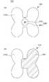
도 3은 도 1에 도시된 접착 유닛의 상면과 하면을 설명하기 위한 평면도이다.
도 4는 도 1에 도시된 의료용 튜브 고정 어셈블리에 의해 신체의 일부에 의료용 튜브가 고정된 모습을 설명하기 위한 사시도이다.
도 5a 내지 도 5c는 도 4에 도시된 의료용 튜브 고정 어셈블리에 의해 의료용 튜브가 신체에 고정되는 모습을 설명하기 위한 사시도이다.
도 6은 도 1에 도시된 의료용 튜브 고정 어셈블리에 의해 신체의 다른 부분에 의료용 튜브가 고정되는 모습을 설명하기 위한 사시도이다.1 is a perspective view for explaining a medical tube fixing assembly according to an embodiment of the present invention;
FIG. 2 is a plan view for explaining the upper surface and the lower surface of the medical tube fixing unit shown in FIG. 1. FIG.
3 is a plan view for explaining the top and bottom surfaces of the bonding unit shown in Fig.
Fig. 4 is a perspective view for explaining how a medical tube is fixed to a part of a body by the medical tube fixing assembly shown in Fig. 1. Fig.
5A to 5C are perspective views for explaining how the medical tube is fixed to the body by the medical tube fixing assembly shown in Fig.
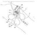
Fig. 6 is a perspective view for explaining how the medical tube is fixed to another part of the body by the medical tube fixing assembly shown in Fig. 1. Fig.
본 고안의 이점 및 특징, 그리고 그것들을 달성하는 방법은 첨부되는 도면과 함께 상세하게 후술되어 있는 실시예들을 참조하면 명확해질 것이다. 그러나 본 고안은 이하에서 개시되는 실시예들에 한정되는 것이 아니라 서로 다른 다양한 형태로 구현될 것이며, 단지 본 실시예들은 본 고안의 개시가 완전하도록 하며, 본 고안이 속하는 기술분야에서 통상의 지식을 가진 자에게 고안의 범주를 완전하게 알려주기 위해 제공되는 것이며, 본 고안은 청구항의 범주에 의해 정의될 뿐이다.BRIEF DESCRIPTION OF THE DRAWINGS The advantages and features of the present invention, and how to accomplish them, will become apparent with reference to the embodiments described in detail below with reference to the accompanying drawings. It should be understood, however, that the present invention is not limited to the embodiments disclosed herein but may be embodied in many different forms and should not be construed as being limited to the embodiments set forth herein. Rather, these embodiments are provided so that this disclosure will be thorough and complete and will fully convey the concept of the invention to those skilled in the art. Is provided to fully inform the owner of the category of design, and the design is only defined by the scope of the claim.
소자(elements) 또는 층이 다른 소자 또는 층"위(on)"로 지칭되는 것은 다른 소자 바로 위에 또는 중간에 다른 층 또는 다른 소자를 개재한 경우를 모두 포함한다.It is to be understood that elements or layers are referred to as being "on " other elements or layers, including both intervening layers or other elements directly on or in between.
비록 제1, 제2 등이 다양한 구성요소들을 서술하기 위해서 사용되나, 이들 구성요소들은 이들 용어에 의해 제한되지 않음은 물론이다. 이들 용어들은 단지 하나의 구성요소를 다른 구성요소와 구별하기 위하여 사용하는 것이다. 따라서, 이하에서 언급되는 제1 구성요소는 본 고안의 기술적 사상 내에서 제2 구성요소일 수도 있음은 물론이다.Although the first, second, etc. are used to describe various components, it goes without saying that these components are not limited by these terms. These terms are used only to distinguish one component from another. Therefore, it goes without saying that the first component mentioned below may be the second component within the technical idea of the present invention.
명세서 전체에 걸쳐 동일 참조 부호는 동일 구성 요소를 지칭한다.Like reference numerals refer to like elements throughout the specification.
도면에서 나타난 각 구성의 크기 및 두께는 설명의 편의를 위해 도시된 것이며, 본 고안이 도시된 구성의 크기 및 두께에 반드시 한정되는 것은 아니다.The sizes and thicknesses of the individual components shown in the figures are shown for convenience of explanation and the present invention is not necessarily limited to the size and thickness of the components shown.
본 고안의 여러 실시예들의 각각 특징들이 부분적으로 또는 전체적으로 서로 결합 또는 조합 가능하며, 당업자가 충분히 이해할 수 있듯이 기술적으로 다양한 연동 및 구동이 가능하며, 각 실시예들이 서로에 대하여 독립적으로 실시 가능할 수도 있고 연관 관계로 함께 실시 가능할 수도 있다.It is to be understood that each of the features of the various embodiments of the present invention may be combined or combined with each other partially or entirely and technically various interlocking and driving is possible as will be appreciated by those skilled in the art, It may be possible to cooperate with each other in association.
이하, 첨부된 도면을 참고로 하여 본 고안에 따른 의료용 튜브 고정 어셈블리에 대해 자세히 설명하기로 한다.Hereinafter, the medical tube fixing assembly according to the present invention will be described in detail with reference to the accompanying drawings.
도 1은 본 고안의 일 실시예에 따른 의료용 튜브 고정 어셈블리(1000)를 설명하기 위한 사시도이다. 도 2는 도 1에 도시된 의료용 튜브 고정 유닛(100)의 상면과 하면을 설명하기 위한 평면도이다. 도 3은 도 1에 도시된 접착 유닛(200)의 상면과 하면을 설명하기 위한 평면도이다.1 is a perspective view for explaining a medical
도 2의 (a)는 의료용 튜브 고정 유닛(100)의 상면을 설명하기 위한 평면도이고, (b)는 의료용 튜브 고정 유닛(100)의 하면을 설명하기 위한 평면도이다. 도 3의 (a)는 접착 유닛(200)의 상면을 설명하기 위한 평면도이고, (b)는 접착 유닛(200)의 하면을 설명하기 위한 평면도이다.Fig. 2 (a) is a plan view for explaining the upper surface of the medical
도 1 내지 도 3을 참조하면, 본 고안의 일 실시예에 따른 의료용 튜브 고정 어셈블리(1000)는 의료용 튜브 고정 유닛(100)과 의료용 튜브 고정 유닛(100)이 착탈 가능하게 결합되는 접착 유닛(200)을 포함한다.1 to 3, a medical
의료용 튜브 고정 유닛(100)은 제1 바디(110), 제2 바디(120), 연성고정부(130) 및 삽입홈(140)를 포함한다.The medical
제1 바디(110)에는 의료용 튜브를 고정할 수 있는 연성고정부(130)가 배치된다. 제1 바디(110)는 상부에서 보았을 때 대략적으로 타원인 형태를 이룬다. 그리고, 의료용 튜브는 타원의 짧은 직경 방향으로, 제1 바디(110)를 통과하며 제1 바디(110)에 고정된다. 이에 대한 상세한 설명은 연성고정부(130)를 설명할 때 후술하기로 한다.The
제2 바디(120)는 제1 바디(110)의 상면이 덮히거나 제1 바디(110)의 상면이 오픈되도록, 제1 바디(110)와 대응되는 면적을 가지며 제1 바디(110)의 일단에 회전 가능하게 힌지 연결 된다.The
제2 바디(120)는 결합돌기부(170)와 누름해제부(160)를 더 포함한다.The
결합돌기부(170)는 후술할 결합돌기수용부(150)와 결합되며, 이에 따라 제1 바디(110)와 제2 바디(120)가 결합된다. 또한, 결합돌기부(170)와 결합돌기수용부(150)가 결합되었을 때, 누름해제부(160)를 누름 조작함으로써, 결합돌기부(170)를 결합돌기수용부(150)로부터 탈거시킬 수 있으며, 이에 따라 제2 바디(120)와 제1 바디(110)가 이루는 각도가 커져, 제1 바디(110)의 상면이 오픈될 수 있다.The
연성고정부(130)는 제1 바디(110)에 배치되고, 의료용 튜브가 용이하게 삽입되거나 인출되도록 신축성이 높은 연성재질로 형성된다. 구체적으로, 연성고정부(130)는 고무재질로 형성될 수 있다. 연성고정부(130)는 의료용 튜브가 삽입되거나 인출되도록 형성되는 의료용 튜브 삽입홈(131)을 포함한다.The
한편, 연성고정부(130)는 적어도 하나의 고정홈(135)을 포함한다. 고정홈(135)은 연성고정부(130)의 깊이 방향으로 연장되게 형성된다. 그리고, 제2 바디(120)는 제1 바디(110)를 덮도록 배치되는 경우, 상술한 고정홈(135)에 대응되는 위치에 배치되는 고정돌기부(122)를 포함한다. 고정돌기부(122)는 제2 바디(120)가 제1 바디(110)를 덮는 위치에 배치되는 경우, 고정홈(135)에 삽입된다. 따라서, 제2 바디(120)가 제1 바디(110)를 덮는 경우, 고정돌기부(122)가 고정홈(135)에 삽입됨으로써, 제1 바디(110)와 제2 바디(200)가 서로 접하는 평면방향으로의 이격을 저감시키는 역할을 한다.On the other hand, the
의료용 튜브 삽입홈(131)은 적어도 일부에서 굴곡지게 형성된다. 구체적으로 도 2를 참조하면, 의료용 튜브 삽입홈(131)은 중앙 부분이 결합돌기수용부(150)쪽으로 가까워지도록 굴곡지게 형성된다. 이러한 의료용 튜브 삽입홈(131)의 굴곡은, 의료용 튜브가 삽입된 후, 의료용 튜브가 잡아당겨지거나, 어떤 물체에 걸려서 외력을 받는 때에 의료용 튜브가 의료용 튜브 고정 유닛(100) 내에서 이동되기 어렵게 할 수 있다.The medical
삽입홈(140)는 제1 바디(110)의 후면에 돌출부(220)가 삽입되도록 형성된다. 구체적으로 도 1 내지 도 3을 참조하면, 의료용 튜브 고정 유닛(100)의 제1 바디(110)의 후면과 접착 유닛(200)의 상면이 서로 착탈 가능하게 결합된다. 이 때, 후에 자세하게 설명할 접착 유닛(200)의 돌출부(220)가 삽입 가능하도록, 돌출부(220)의 결합돌기(222)와 대응되는 위치에 삽입홈(140)가 형성된다. 또한, 결합돌기(222)의 상단부는 하단부보다 넓은 면적으로 형성된다. 삽입홈(140)의 개구된 영역은 결합돌기(222)가 삽입되어 상단부가 걸림되도록, 결합돌기(222)의 상단부의 면적보다 다소 작은 크기로 형성되는 것이 바람직하다.The
접착 유닛(200)은 몸체부(210) 및 돌출부(220)를 포함한다.The
몸체부(210)는 굴곡진 신체를 감싸며 용이하게 접착되도록 둘레의 적어도 일부가 곡률을 가지도록 형성된다. 예를 들어, 도 3을 참조하면, 적어도 일부가 타원의 형상을 갖는 네 개의 잎사귀가 모여 있는 형상으로 형성될 수 있다. 이러한 형상은, 신체의 팔목이나 발목이 대략의 원통형으로 형성되어 길이 방향 또는 너비 방향으로 접착 유닛(200)을 신체에 부착할 경우, 몸체부(210)는 유선형 모양인 팔목이나 발목을 자연스럽게 감싸며 부착될 수 있다. 이에 따라, 접착 유닛(200)의 신체에 대한 접착력을 높일 수 있다. 또한 네 개의 잎사귀 모양 사이에는 내측으로 리세스된 홈들이 있으므로, 신체에서 관절이 있는 부분에도 용이하게 부착될 수 있는 장점이 있다.The
몸체부(210)의 일면에는 돌출부(220)가 부착된다. 돌출부(220)는 플레이트(221)와 고정돌기(222)로 이루어진다. 구체적으로 도 3을 참조하면, 돌출부(220)는 몸체부(210)의 일면의 중앙부분에 부착된다. 플레이트(221)는 돌출부(220)가 몸체부(210)에 견고히 접착될 수 있도록, 기결정된 면적 이상으로 형성되는 것이 바람직하다. 고정돌기(222)는 플레이트(221)의 중앙부에서 몸체부(210)의 면 방향과 수직하게 돌출된다. 상술한 바와 같이, 고정돌기(222)는 의료용 튜브 고정 유닛(100)의 삽입홈(140)에 삽입가능하다. 이 때, 접착 유닛(200)은, 의료용 튜브 고정 유닛(100)은 접착 유닛(200)과 결합된 상태에서 회전이 가능하다.A
몸체부(210)의 타면에는 신체에 접착 가능한 접착면(210b)이 배치된다. 또한, 접착면(210b)을 덮도록 배치되고, 접착면(210b)에서 분리가능한 이형지를 더 포함할 수 있다. 몸체부(210)를 신체에 부착하기 전에는 이형지(230)를 제거하지 않으며, 몸체부(210)를 신체에 부착하기 직전 이형지(230)를 제거할 수 있다.On the other surface of the
도 4는 도 1에 도시된 의료용 튜브 고정 어셈블리(1000)에 의해 신체의 일부에 의료용 튜브(11)가 고정된 모습을 설명하기 위한 사시도이다. 도 5a 내지 도 5c는 도 4에 도시된 의료용 튜브 고정 어셈블리(1000) 의해 의료용 튜브(11)가 신체에 고정되는 모습을 설명하기 위한 사시도이다.4 is a perspective view for explaining a state in which the
우선 도 4 및 도 5a를 참조하면, 환자의 환부에 주사기(10)를 삽입한 후, 주사기(10)를 환자의 신체에 테이프 등으로 고정시킬 수 있다. 그리고, 의료용 튜브(11)는 주사기(10)로부터 연장될 수 있다.4 and 5A, after the
다음으로, 도 5b를 참조하면, 환자의 환부에 가까운 부분에 접착 유닛(200)이 부착될 수 있다. 이 때, 의료용 튜브(11)를 고정시키고 싶은 지점(SPOT)이 접착 유닛(200)의 돌출부에 위치하도록, 접착 유닛(200)을 신체에 부착시키는 것이 바람직하다.Next, referring to FIG. 5B, the
다음으로, 도 5c를 참조하면, 의료용 튜브 고정 유닛(100)에 의료용 튜브(11)를 삽입하여, 의료용 튜브(11)를 의료용 튜브 고정 유닛(100)에 고정시킨다. 구체적으로, 의료용 튜브 고정 유닛(100)의 연성고정부(130)에 형성되는 의료용 튜브 삽입홈(131)에 의료용 튜브(11)를 삽입하게 된다. 그 후, 제2 바디(120)가 제1 바디(110)를 덮도록 제2 바디(120)를 회동 시킨다. 회동된 제2 바디(120)는 상술한 바와 같이, 결합돌기부(170)가 결합돌기수용부(150)에 결합됨으로써 제1 바디(110)와 결합된다. 이러한 결합으로 인해, 의료용 튜브(11)는 의료용 튜브 고정 유닛(100)에 견고하게 결합된다.Next, referring to FIG. 5C, the
그 후, 의료용 튜브 고정 유닛(100)은 상술한 바와 같이 접착 유닛(200)의 돌출부(222)에 결합된다. 구체적으로 상술한 바와 같이 의료용 튜브 고정 유닛(100)의 제1 바디(110)의 하면에 형성된 삽입홈(140)와, 접착 유닛(200)의 상면에 배치되고 돌출되는 돌출부(222)가 서로 결합되어, 의료용 튜브 고정 유닛(100)과 접착 유닛(200)이 서로 고정된다.Thereafter, the medical
다만, 상술한 바와 같이 신체에 접착 유닛(200)이 먼저 부착되고, 그 후에 의료용 튜브 고정 유닛(100)에 의료용 튜브(11)가 고정된 다음, 의료용 튜브 고정 유닛(100)과 접착 유닛(200)이 결합되는 것에 한정되는 것이 아니다. 구체적으로, 접착 유닛(200) 및 의료용 튜브 고정 유닛(100)이 선행하여 결합되고, 그 후에 의료용 튜브 고정 유닛(100)에 의료용 튜브(11)가 결합되는 방식을 취하여도 무방하다.After the
도 6은 도 1에 도시된 의료용 튜브 고정 어셈블리에 의해 신체의 다른 부분에 의료용 튜브가 고정되는 모습을 설명하기 위한 사시도이다.Fig. 6 is a perspective view for explaining how the medical tube is fixed to another part of the body by the medical tube fixing assembly shown in Fig. 1. Fig.
도 6에 도시된 의료용 튜브 고정 어셈블리(1000)는 도 4에 도시된 의료용 튜브 고정 어셈블리(1000)와 비교하였을 때에, 환자의 신체 내에 부착되는 위치만 다를 뿐 다른 구성요소들은 실질적으로 동일하므로 중복 설명을 생략한다.The medical
상술한 바와 같이 본 발명의 일 실시예에 따른 의료용 튜브 고정 어셈블리(1000)는 환자의 팔이나 다리와 같은 곳에 쓰이는 의료용 튜브(11)를 고정할 수도 있지만 이에 한정되지는 않는다. 구체적으로 도 6을 참조하면, 본 발명의 일 실시예에 따른 의료용 튜브 고정 어셈블리(1000)는 복부(5)에 0.5 내지 1.5cm 크기의 작은 구멍(6, 절개창)을 여러 개 내고, 그 안으로 비디오 카메라와 각종 기구들을 넣고 시행하는 복강경 수술에 쓰이는 의료용 튜브(11)를 고정하는 용도로 사용 가능하다. 복강경 수술에 쓰이는 의료용 튜브(11)는 팔이나 다리에 삽입되는 주사기에 쓰이는 의료용 튜브보다 그 직경이 더 크다. 본 발명의 일 실시예에 따른 의료용 튜브 고정 어셈블리(1000)는 이러한 두꺼운 직경의 의료용 튜브(11)를 고정하는데에도 제한없이 사용 가능하다.As described above, the medical
이상 첨부된 도면을 참조하여 본 고안의 실시예들을 설명하였지만, 본 고안이 속하는 기술분야에서 통상의 지식을 가진 자는 본 고안의 그 기술적 사상이나 필수적인 특징을 변경하지 않고서 다른 구체적인 형태로 실시될 수 있다는 것을 이해할 수 있을 것이다. 그러므로 이상에서 기술한 실시예들은 모든 면에서 예시적인 것이며 한정적이 아닌 것으로 이해해야만 한다.While the present invention has been particularly shown and described with reference to exemplary embodiments thereof, it is evident that many alternatives, modifications and variations will be apparent to those skilled in the art. You will understand. It is therefore to be understood that the above-described embodiments are illustrative in all aspects and not restrictive.
10 : 주사기
11 : 의료용 튜브
100 : 의료용 튜브 고정 유닛
110 : 제1 바디
120 : 제2 바디
130 : 연성고정부
140 : 삽입홈
150 : 결합돌기수용부
160 : 누름해제부
170 : 결합돌기부
200 : 접착 유닛
210 : 몸체부
220 : 돌출부
1000 : 의료용 튜브 고정 어셈블리10: Syringe
11: medical tube
100: Medical tube fixing unit
110: first body
120: Second body
130:
140: insertion groove
150: engaging projection receiving portion
160:
170:
200: Adhesive unit
210:
220: protrusion
1000: Medical tube fixing assembly
Claims (5)
Translated fromKorean상기 접착 유닛은,
일면에 신체에 접착 가능한 접착면을 포함하는 몸체부;
상기 몸체부의 타면에 부착되고, 상기 의료용 튜브 고정 유닛에 삽입 가능하도록 돌출되는 돌출부를 포함하며,
상기 의료용 튜브 고정 유닛은,
제1 바디;
상기 제1 바디의 상면이 덮히거나 상기 제1 바디의 상면이 오픈되도록, 상기 제1 바디와 대응되는 면적으로 가지며 상기 제1 바디의 일단에 회전 가능하게 힌지연결 되는 제2 바디;
상기 제1 바디에 배치되고, 의료용 튜브가 용이하게 삽입되거나 인출되도록 신축성이 높은 연성재질로 형성되는 연성고정부; 및
상기 제1 바디의 후면에 상기 돌출부가 삽입되도록 형성되는 삽입홈을 포함하고,
상기 접착 유닛은,
상기 의료용 튜브 고정 유닛은 상기 접착 유닛과 결합된 상태에서 회전가능한 의료용 튜브 고정 어셈블리.A medical tube securing assembly comprising a medical tube securing unit and an adhesive unit to which the medical tube securing unit is detachably coupled,
Wherein the adhesive unit comprises:
A body portion including a bonding surface adherable to the body on one surface;
And a protrusion attached to the other surface of the body portion and protruding to be insertable into the medical tube fixing unit,
Wherein the medical tube fixing unit comprises:
A first body;
A second body having an area corresponding to the first body and hingedly connected to one end of the first body such that an upper surface of the first body is covered or an upper surface of the first body is opened;
A flexible fastener disposed on the first body and formed of a flexible material having a high elasticity such that the medical tube can be easily inserted or withdrawn; And
And an insertion groove formed in the rear surface of the first body to insert the protrusion,
Wherein the adhesive unit comprises:
And the medical tube fixing unit is rotatable in a state of being engaged with the adhesive unit.
상기 연성고정부는 상기 의료용 튜브가 삽입되거나 인출되도록 형성되는 의료용 튜브 삽입홈을 포함하며,
상기 의료용 튜브 삽입홈은 적어도 일부에서 굴곡지게 형성되는, 의료용 튜브 고정 어셈블리.The method according to claim 1,
Wherein the flexible fastening portion includes a medical tube insertion groove formed to insert or withdraw the medical tube,
Wherein the medical tube insertion groove is formed to be curved at least in part.
상기 연성고정부는 깊이 방향으로 연장되는 적어도 하나의 고정홈이 형성되고
상기 제2 바디는,
상기 제1 바디와 결합시 상기 연성고정부와 마주하는 면에서 상기 적어도 하나의 고정홈에 대응하여 돌출되는 고정돌기부를 포함하는, 의료용 튜브 고정 어셈블리.The method according to claim 1,
The flexible fastening part is formed with at least one fixing groove extending in the depth direction
The second body may include:
And a fixing protrusion protruding corresponding to the at least one fixing groove on a surface facing the soft fixing part when the first body is coupled with the first body.
상기 접착 유닛의 몸체부는,
굴곡진 신체를 감싸며 용이하게 접착되도록 둘레의 적어도 일부가 곡률을 가지도록 형성되는, 의료용 튜브 고정 어셈블리.The method according to claim 1,
Wherein the body portion of the adhesive unit comprises:
Wherein at least a portion of the circumference is formed to have a curvature so as to easily adhere to the curved body.
상기 접착면을 덮도록 배치되고, 상기 접착면에서 분리가능한 이형지를 더 포함하는, 의료용 튜브 고정 어셈블리.The method according to claim 1,
Further comprising a release paper disposed to cover the adhesive surface and removable from the adhesive surface.
Priority Applications (1)
| Application Number | Priority Date | Filing Date | Title |
|---|---|---|---|
| KR2020160000507UKR200484648Y1 (en) | 2016-01-28 | 2016-01-28 | Medical tube fixing assembly |
Applications Claiming Priority (1)
| Application Number | Priority Date | Filing Date | Title |
|---|---|---|---|
| KR2020160000507UKR200484648Y1 (en) | 2016-01-28 | 2016-01-28 | Medical tube fixing assembly |
Publications (2)
| Publication Number | Publication Date |
|---|---|
| KR20170002803Utrue KR20170002803U (en) | 2017-08-07 |
| KR200484648Y1 KR200484648Y1 (en) | 2017-10-11 |
Family
ID=60407852
Family Applications (1)
| Application Number | Title | Priority Date | Filing Date |
|---|---|---|---|
| KR2020160000507UActiveKR200484648Y1 (en) | 2016-01-28 | 2016-01-28 | Medical tube fixing assembly |
Country Status (1)
| Country | Link |
|---|---|
| KR (1) | KR200484648Y1 (en) |
Cited By (3)
| Publication number | Priority date | Publication date | Assignee | Title |
|---|---|---|---|---|
| KR102120257B1 (en)* | 2018-12-03 | 2020-06-08 | 동의대학교 산학협력단 | Catheter securing device |
| KR102522980B1 (en)* | 2022-11-10 | 2023-04-18 | 주식회사 코빌드 | Medical mouthpiece |
| KR102831715B1 (en)* | 2025-02-11 | 2025-07-07 | 박지은 | Rotary type infusion tube holder |
Citations (2)
| Publication number | Priority date | Publication date | Assignee | Title |
|---|---|---|---|---|
| KR20110050193A (en)* | 2009-11-06 | 2011-05-13 | 이정숙 | Urinary Hose Fixation Device |
| KR200474714Y1 (en)* | 2014-03-10 | 2014-10-13 | (주)지온메드 | Medical tube fixing device |
- 2016
- 2016-01-28KRKR2020160000507Upatent/KR200484648Y1/enactiveActive
Patent Citations (2)
| Publication number | Priority date | Publication date | Assignee | Title |
|---|---|---|---|---|
| KR20110050193A (en)* | 2009-11-06 | 2011-05-13 | 이정숙 | Urinary Hose Fixation Device |
| KR200474714Y1 (en)* | 2014-03-10 | 2014-10-13 | (주)지온메드 | Medical tube fixing device |
Cited By (4)
| Publication number | Priority date | Publication date | Assignee | Title |
|---|---|---|---|---|
| KR102120257B1 (en)* | 2018-12-03 | 2020-06-08 | 동의대학교 산학협력단 | Catheter securing device |
| KR102522980B1 (en)* | 2022-11-10 | 2023-04-18 | 주식회사 코빌드 | Medical mouthpiece |
| WO2024101655A1 (en)* | 2022-11-10 | 2024-05-16 | 주식회사 코빌드 | Medical mouthpiece |
| KR102831715B1 (en)* | 2025-02-11 | 2025-07-07 | 박지은 | Rotary type infusion tube holder |
Also Published As
| Publication number | Publication date |
|---|---|
| KR200484648Y1 (en) | 2017-10-11 |
Similar Documents
| Publication | Publication Date | Title |
|---|---|---|
| US6689051B2 (en) | Endoscope hood for mucous membrane resection | |
| US10893872B2 (en) | Hemostatic device | |
| AU2019414202B2 (en) | Medicine administering device and medicine administering system | |
| EP3815629B1 (en) | Compression device | |
| US10779840B2 (en) | Hemostatic device | |
| EP3788966B1 (en) | Compression device | |
| US10939919B2 (en) | Hemostatic device | |
| US10575859B2 (en) | Hemostatic device | |
| BR112018077484B1 (en) | HEMOSTATIC DEVICE TO STOP BLEEDING AT A PERFORATION SITE | |
| JP2007216029A (en) | Straight insertion safety infusion set | |
| US20120232587A1 (en) | Wound Closing Device | |
| JP2009545341A (en) | Cannula and delivery device | |
| US12251545B2 (en) | Injection analgesia system | |
| KR200484648Y1 (en) | Medical tube fixing assembly | |
| US10980945B1 (en) | Syringe aid | |
| JP2012010823A (en) | Hemostatic unit with marker | |
| RU2392977C2 (en) | Adjusting patch, adhesion device comprising such adjusting patch, and methods of applying said device on patient | |
| CN107847684B (en) | Dialysis needle | |
| WO2018008604A1 (en) | Hemostatic instrument | |
| KR20170116803A (en) | T-type needle connector and its fixing band for an injection set of medical solution | |
| KR101459313B1 (en) | Apparatus for fixing medical suction unit | |
| KR100749844B1 (en) | Adhesive Band for Ringer Needle | |
| RU108943U1 (en) | HEMOSTATIC DEVICE | |
| EP4302709A1 (en) | Hemostatic instrument | |
| JP4136647B2 (en) | Hemostatic device |
Legal Events
| Date | Code | Title | Description |
|---|---|---|---|
| A201 | Request for examination | ||
| UA0108 | Application for utility model registration | Comment text:Application for Utility Model Registration Patent event code:UA01011R08D Patent event date:20160128 | |
| UA0201 | Request for examination | ||
| E902 | Notification of reason for refusal | ||
| UE0902 | Notice of grounds for rejection | Comment text:Notification of reason for refusal Patent event code:UE09021S01D Patent event date:20170510 | |
| E701 | Decision to grant or registration of patent right | ||
| UE0701 | Decision of registration | Patent event date:20170803 Comment text:Decision to Grant Registration Patent event code:UE07011S01D | |
| UG1501 | Laying open of application | ||
| REGI | Registration of establishment | ||
| UR0701 | Registration of establishment | Patent event date:20170927 Patent event code:UR07011E01D Comment text:Registration of Establishment | |
| UR1002 | Payment of registration fee | Start annual number:1 End annual number:3 Payment date:20170927 | |
| UG1601 | Publication of registration | ||
| UR1001 | Payment of annual fee | Payment date:20200723 Start annual number:4 End annual number:4 | |
| UR1001 | Payment of annual fee | Payment date:20210713 Start annual number:5 End annual number:5 | |
| UR1001 | Payment of annual fee | Payment date:20220721 Start annual number:6 End annual number:6 | |
| UR1001 | Payment of annual fee | Payment date:20230704 Start annual number:7 End annual number:7 | |
| UR1001 | Payment of annual fee | Payment date:20240715 Start annual number:8 End annual number:8 | |
| UR1001 | Payment of annual fee | Payment date:20250702 Start annual number:9 End annual number:9 |