KR20170001527U - Led module improved connecting structuer and lamp device using the same - Google Patents
Led module improved connecting structuer and lamp device using the sameDownload PDFInfo
- Publication number
- KR20170001527U KR20170001527UKR2020150006871UKR20150006871UKR20170001527UKR 20170001527 UKR20170001527 UKR 20170001527UKR 2020150006871 UKR2020150006871 UKR 2020150006871UKR 20150006871 UKR20150006871 UKR 20150006871UKR 20170001527 UKR20170001527 UKR 20170001527U
- Authority
- KR
- South Korea
- Prior art keywords
- substrate
- terminal
- led module
- protruding
- led
- Prior art date
- Legal status (The legal status is an assumption and is not a legal conclusion. Google has not performed a legal analysis and makes no representation as to the accuracy of the status listed.)
- Ceased
Links
Images


Classifications
- F—MECHANICAL ENGINEERING; LIGHTING; HEATING; WEAPONS; BLASTING
- F21—LIGHTING
- F21V—FUNCTIONAL FEATURES OR DETAILS OF LIGHTING DEVICES OR SYSTEMS THEREOF; STRUCTURAL COMBINATIONS OF LIGHTING DEVICES WITH OTHER ARTICLES, NOT OTHERWISE PROVIDED FOR
- F21V23/00—Arrangement of electric circuit elements in or on lighting devices
- F21V23/001—Arrangement of electric circuit elements in or on lighting devices the elements being electrical wires or cables
- F21V23/002—Arrangements of cables or conductors inside a lighting device, e.g. means for guiding along parts of the housing or in a pivoting arm
- F—MECHANICAL ENGINEERING; LIGHTING; HEATING; WEAPONS; BLASTING
- F21—LIGHTING
- F21K—NON-ELECTRIC LIGHT SOURCES USING LUMINESCENCE; LIGHT SOURCES USING ELECTROCHEMILUMINESCENCE; LIGHT SOURCES USING CHARGES OF COMBUSTIBLE MATERIAL; LIGHT SOURCES USING SEMICONDUCTOR DEVICES AS LIGHT-GENERATING ELEMENTS; LIGHT SOURCES NOT OTHERWISE PROVIDED FOR
- F21K9/00—Light sources using semiconductor devices as light-generating elements, e.g. using light-emitting diodes [LED] or lasers
- F—MECHANICAL ENGINEERING; LIGHTING; HEATING; WEAPONS; BLASTING
- F21—LIGHTING
- F21S—NON-PORTABLE LIGHTING DEVICES; SYSTEMS THEREOF; VEHICLE LIGHTING DEVICES SPECIALLY ADAPTED FOR VEHICLE EXTERIORS
- F21S2/00—Systems of lighting devices, not provided for in main groups F21S4/00 - F21S10/00 or F21S19/00, e.g. of modular construction
- F21S2/005—Systems of lighting devices, not provided for in main groups F21S4/00 - F21S10/00 or F21S19/00, e.g. of modular construction of modular construction
- F—MECHANICAL ENGINEERING; LIGHTING; HEATING; WEAPONS; BLASTING
- F21—LIGHTING
- F21S—NON-PORTABLE LIGHTING DEVICES; SYSTEMS THEREOF; VEHICLE LIGHTING DEVICES SPECIALLY ADAPTED FOR VEHICLE EXTERIORS
- F21S4/00—Lighting devices or systems using a string or strip of light sources
- F21S4/20—Lighting devices or systems using a string or strip of light sources with light sources held by or within elongate supports
- F21S4/28—Lighting devices or systems using a string or strip of light sources with light sources held by or within elongate supports rigid, e.g. LED bars
- F—MECHANICAL ENGINEERING; LIGHTING; HEATING; WEAPONS; BLASTING
- F21—LIGHTING
- F21V—FUNCTIONAL FEATURES OR DETAILS OF LIGHTING DEVICES OR SYSTEMS THEREOF; STRUCTURAL COMBINATIONS OF LIGHTING DEVICES WITH OTHER ARTICLES, NOT OTHERWISE PROVIDED FOR
- F21V17/00—Fastening of component parts of lighting devices, e.g. shades, globes, refractors, reflectors, filters, screens, grids or protective cages
- F21V17/10—Fastening of component parts of lighting devices, e.g. shades, globes, refractors, reflectors, filters, screens, grids or protective cages characterised by specific fastening means or way of fastening
- F21V17/12—Fastening of component parts of lighting devices, e.g. shades, globes, refractors, reflectors, filters, screens, grids or protective cages characterised by specific fastening means or way of fastening by screwing
- F—MECHANICAL ENGINEERING; LIGHTING; HEATING; WEAPONS; BLASTING
- F21—LIGHTING
- F21Y—INDEXING SCHEME ASSOCIATED WITH SUBCLASSES F21K, F21L, F21S and F21V, RELATING TO THE FORM OR THE KIND OF THE LIGHT SOURCES OR OF THE COLOUR OF THE LIGHT EMITTED
- F21Y2101/00—Point-like light sources
Landscapes
- Engineering & Computer Science (AREA)
- General Engineering & Computer Science (AREA)
- Physics & Mathematics (AREA)
- Microelectronics & Electronic Packaging (AREA)
- Optics & Photonics (AREA)
- Arrangement Of Elements, Cooling, Sealing, Or The Like Of Lighting Devices (AREA)
- Non-Portable Lighting Devices Or Systems Thereof (AREA)
Abstract
Translated fromKoreanDescription
Translated fromKorean본 고안은 엘이디모듈 및 이를 이용한 등기구에 관한 것으로, 더 상세하게는 외부로 노출되는 입출력단자나 전선 없이 기판이 직접 연결됨으로써 외관이 미려하고 설치작업이 용이한 엘이디모듈 및 이를 이용한 등기구에 관한 것이다.The present invention relates to an LED module and a luminaire using the LED module. More particularly, the present invention relates to an LED module and a luminaire using the LED module, wherein the substrate is directly connected to the LED module.
일반적으로, LED(Light-Emitting Device)는 다른 열변환 발광소자에 비해 안정적이고 신뢰성 있으며, 전력소모가 작고, 그 수명도 길다. 현재 LED 기술은 비약적으로 발전하고 있고, 다양한 색상의 고효율, 고휘도의 LED가 출시되고 있다. LED 하나는 점광원으로 작용하지만, 복수개의 LED가 모이면 선광원이나 면광원으로 작용할 수 있다. LED 기술의 발전으로 단순한 표시 장치에 응용되던 LED의 응용분야도 확대되고 있다.In general, a light-emitting device (LED) is more stable, reliable, consumes less power and has a longer lifetime than other heat conversion light emitting devices. Currently, LED technology is developing rapidly, and various high-efficiency, high-brightness LEDs are being released. One LED acts as a point light source, but if a plurality of LEDs are gathered, it can act as a source of light or a plane light source. With the development of LED technology, the application field of LED that has been applied to simple display devices is also expanding.
최근에는 LED가 평판형 디스플레이에 이용되는 백라이트 유닛의 광원으로 이용되고 있으며, LED의 고휘도화와 더불어 신호등이나 전광판 등 옥외 표시기로 이용이 증가하고 있다. 특히, 바 타입의 LED 모듈은 바 타입의 모듈 조합에 의해 무대 및 실내, 외 디자인에 다양한 형태로 구현이 가능하여, 경관조명, 간판 등에 경관 연출용으로 각광받고 있다.In recent years, LEDs have been used as light sources for backlight units used in flat panel displays, and LEDs have been used in outdoor displays such as traffic lights and electric sign boards in addition to high brightness. In particular, the bar type LED module can be implemented in various forms in the stage, indoor and outdoor design by combination of the bar type module, and is attracting attention for the scenery lighting, the signboard, etc.
이하 첨부된 도면을 참조하여 종래의 엘이디모듈에 관하여 상세히 설명한다.Hereinafter, a conventional LED module will be described in detail with reference to the accompanying drawings.
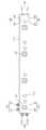
도 1은 종래의 바 타입 엘이디모듈의 사시도이다.1 is a perspective view of a conventional bar type LED module.
도 1에 도시된 바와 같이 종래의 바 타입 엘이디모듈(10)은, 일방향으로 길게 연장된 바 형상의 기판(11)과, 상기 기판(11)의 양측에 구비되어 전원 및 신호를 입출력하는 입출력 단자(12)와, 상기 기판(11)의 상면에 부착되어 상기 입출력 단자(12)를 통해 전달되는 전원 및 신호에 의해 외부에 노출된 상태에서 발광하는 발광소자(13)를 포함하여 구성된다. 상기 엘이디모듈(10)의 일측 입출력 단자(12)에는, 교류전류를 직류로 변환시켜 제공하는 컨버터(20)가 연결된다.1, a conventional bar-
이와 같이 구성되는 종래의 바 타입 엘이디모듈(10)은, 직렬 또는 병렬로 다수 개 배치되어 다양한 형태의 경관 조명을 구현할 수 있는데, 이와 같이 복수 개의 엘이디모듈(10)를 전기적으로 연결하기 위해서는, 이웃하는 두 개의 엘이디모듈(10)에 구비된 입출력단자(12)를 연결하는 전선(14)이 필수적으로 요구된다. 그러나 도 1에 도시된 바와 같이 입출력단자(12) 및 전선(14)이 외부로 노출되면 외관이 미려하지 아니할 뿐만 아니라, 외부 충격에 의해 전선(14)이 파손되어 각 엘이디모듈(10)이 정상적으로 작동되지 아니하는 경우가 빈번하게 발생된다는 문제점이 있다.A plurality of conventional bar
본 고안은 상기와 같은 문제점을 해결하기 위하여 제안된 것으로, 입출력단자 및 전선이 외부로 노출되지 아니하여 외관이 미려하고 내구성이 우수한 엘이디모듈을 제공하는데 목적이 있다. 또한 본 고안은, 상기와 같은 엘이디모듈이 다양한 패턴으로 결합될 수 있어 여러가지 용도로 활용될 수 있는 등기구를 제공하는데 또 다른 목적이 있다.It is an object of the present invention to provide an LED module having excellent appearance and excellent durability because the input / output terminals and the wires are not exposed to the outside. Further, the present invention has another object to provide a luminaire which can be used for various purposes because the LED module can be combined in various patterns.
상기와 같은 목적을 달성하기 위한 본 고안에 의한 엘이디모듈은,According to an aspect of the present invention, there is provided an LED module including:
일방향으로 길게 연장된 바(bar) 형상의 기판;A bar-shaped substrate elongated in one direction;
상기 기판의 상면에 결합되는 발광소자;A light emitting element coupled to an upper surface of the substrate;
상기 기판의 일측에 형성되어 외부로부터 인가된 전원을 상기 발광소자로 전달하는 돌출단자;A protruding terminal formed on one side of the substrate and transmitting power applied from the outside to the light emitting element;
상기 돌출단자가 끼워맞춤 방식으로 삽입될 수 있는 오목한 형상으로 형성되어, 상기 기판의 타측에 구비되는 단자홈;A terminal groove formed on the other side of the substrate, the terminal groove being formed in a concave shape in which the projecting terminal can be inserted in a fitting manner;
을 포함한다..
상기 돌출단자는 상기 기판의 길이방향 일단에 형성되고, 상기 단자홈은 상기 기판의 길이방향 타단에 형성된다.The protruding terminal is formed at one end in the longitudinal direction of the substrate, and the terminal groove is formed at the other end in the longitudinal direction of the substrate.
상기 돌출단자는 상기 기판의 폭방향 일측면에 형성되고, 상기 단자홈은 상기 기판의 폭방향 타측면에 형성된다.The protruding terminal is formed on one side surface in the width direction of the substrate, and the terminal groove is formed on the other side in the width direction of the substrate.
상기 돌출단자는, 상기 기판의 길이방향 일단과, 상기 기판의 폭방향 일측면 중 상기 기판의 길이방향 일측에 각각 형성되고,The protruding terminals are formed at one longitudinal end of the substrate and one lateral side of the substrate in the width direction,
상기 단자홈은, 상기 기판의 길이방향 타단과, 상기 기판의 폭방향 일측면 중 상기 기판의 길이방향 타측과, 상기 기판의 폭방향 타측면 중 상기 기판의 길이방향 양측에 각각 형성된다.The terminal grooves are respectively formed on the other longitudinal side of the substrate and on one side in the longitudinal direction of the substrate among the side surfaces in the width direction of the substrate and on both sides in the longitudinal direction of the substrate on the other side in the width direction of the substrate.
상기 돌출단자는, 양극돌출단자와 음극돌출단자로 구성되고,Wherein the projecting terminal is composed of an anode projecting terminal and a cathode projecting terminal,
상기 단자홈은, 양극단자홈과 음극단자홈으로 구성되며,The terminal groove is composed of a positive terminal groove and a negative terminal groove,
상기 양극돌출단자는 상기 양극단자홈과 전기적으로 연결되고, 상기 음극돌출단자는 상기 음극단자홈에 삽입된다.The positive electrode projection terminal is electrically connected to the positive electrode terminal groove, and the negative electrode projection terminal is inserted into the negative electrode terminal groove.
상기 기판에는 상하방향으로 관통하는 둘 이상의 나사홀이 형성된다.The substrate is provided with two or more screw holes penetrating in the vertical direction.
상기 기판의 저면에는 양면테이프가 부착된다.A double-sided tape is attached to the bottom surface of the substrate.
본 고안에 의한 등기구는,In the luminaire according to the present invention,
상기와 같이 구성되는 둘 이상의 엘이디모듈과, 상기 엘이디모듈로 직류전원을 공급하는 컨버터를 포함하되,And at least two LED modules configured as described above, and a converter for supplying DC power to the LED module,
어느 하나의 엘이디모듈 단자홈에 다른 하나의 엘이디모듈 돌출단자가 삽입되어, 복수 개의 엘이디모듈이 일체로 결합되고,Another LED module protrusion terminal is inserted into one of the LED module terminal grooves so that a plurality of LED modules are integrally coupled,
상기 컨버터는 둘 이상의 엘이디모듈 중 어느 하나의 엘이디모듈 돌출단자에 직류전원을 인가하도록 결합된다.The converter is coupled to apply DC power to the LED module protruding terminal of any one of the two or more LED modules.
상기 복수 개의 엘이디모듈이 일렬로 배열되거나, 다각형을 이루도록 배열되거나, 폭방향으로 연이어 배열되도록 구성된다.The plurality of LED modules may be arranged in a row, a polygonal shape, or arranged in the width direction.
본 고안에 의한 엘이디모듈은, 입출력단자 및 전선이 외부로 노출되지 아니하여 외관이 미려하고 내구성이 우수하다는 장점이 있다. 또한 본 고안에 의한 등기구는, 상기와 같은 엘이디모듈이 다양한 패턴으로 결합될 수 있어 여러가지 용도로 활용될 수 있다는 장점이 있다.The LED module according to the present invention is advantageous in that the input / output terminal and the electric wire are not exposed to the outside, and the appearance is good and the durability is excellent. Also, the lamp according to the present invention has an advantage that the LED module can be combined in various patterns and can be utilized for various purposes.
도 1은 종래의 엘이디모듈 사시도이다.
도 2는 본 고안에 의한 엘이디모듈의 사시도이다.
도 3은 본 고안에 의한 엘이디모듈의 저면사시도이다.
도 4는 본 고안에 의한 엘이디모듈의 평면도이다.
도 5는 본 고안에 의한 엘이디모듈의 배선도이다.
도 6은 본 고안에 의한 등기구 제1 실시예의 평면도이다.
도 7은 본 고안에 의한 등기구 제2 실시예의 평면도이다.
도 8은 본 고안에 의한 등기구 제3 실시예의 평면도이다.1 is a perspective view of a conventional LED module.
2 is a perspective view of the LED module according to the present invention.
3 is a bottom perspective view of the LED module according to the present invention.
4 is a plan view of the LED module according to the present invention.
5 is a wiring diagram of the LED module according to the present invention.
6 is a plan view of the first embodiment of the lamp according to the present invention.
7 is a plan view of the second embodiment of the lamp according to the present invention.
8 is a plan view of the third embodiment of the lamp according to the present invention.
이하 첨부된 도면을 참조하여 본 고안에 의한 엘이디모듈 및 이를 포함하는 등기구의 실시예를 상세히 설명한다.DETAILED DESCRIPTION OF THE PREFERRED EMBODIMENTS Hereinafter, embodiments of an LED module and a luminaire including the same according to the present invention will be described in detail with reference to the accompanying drawings.
도 2는 본 고안에 의한 엘이디모듈의 사시도이고, 도 3은 본 고안에 의한 엘이디모듈의 저면사시도이며, 도 4는 본 고안에 의한 엘이디모듈의 평면도이고, 도 5는 본 고안에 의한 엘이디모듈의 배선도이다.FIG. 2 is a perspective view of the LED module according to the present invention, FIG. 3 is a bottom perspective view of the LED module according to the present invention, FIG. 4 is a plan view of the LED module according to the present invention, It is a wiring diagram.
본 고안에 의한 엘이디모듈(100)은 일방향으로 길게 연장된 기판(110)상에 다수 개의 발광소자(120)가 장착되어 조명이나 간판 용도로 사용되는 조명장치의 일종으로서, 서로 다른 두 개의 엘이디모듈(100)이 별도의 전선 없이 단자가 직접 결합되는바, 외관이 미려하고 내구성이 우수하다는 점에 구성상의 특징이 있다.The
즉, 본 고안에 의한 엘이디모듈(100)은, 일방향으로 길게 연장된 바(bar) 형상의 기판(110)과, 상기 기판(110)의 상면에 결합되는 발광소자(120)와, 상기 기판(110)의 일측에 형성되어 외부로부터 인가된 전원을 상기 발광소자(120)로 전달하는 돌출단자(130)와, 상기 돌출단자(130)가 삽입될 수 있는 오목한 형상으로 형성되어, 상기 기판(110)의 타측에 구비되는 단자홈(140)을 포함하여 구성된다.That is, the
상기 돌출단자(130)와 단자홈(140)은 상호 결합되었을 때 전기적으로 연결되므로 서로 다른 두 개의 엘이디모듈(100)은 별도의 전선 없이 통전될 수 있고, 상기 돌출단자(130)와 단자홈(140)은 억지끼워맞춤 방식으로 삽입되는바 별도의 체결수단 없이 두 개의 엘이디모듈(100)이 일체로 결합된다. 따라서 본 고안에 의한 엘이디모듈(100)은 전기적 연결 및 구조적 연결을 위한 구성이 매우 간단해지므로, 외관이 미려하고 구조적 강도가 매우 개선된다는 장점이 있다. 또한, 다수 개의 엘이디모듈(100)을 연결하는 작업이 매우 간단하므로 엘이디모듈(100) 설치에 소요되는 시간이 현저히 단축될 수 있다는 장점도 있다.Since the two
이때, 단자홈(140)에 삽입된 돌출단자(130)가 쉽게 빠지지 아니하도록, 상기 돌출단자(130)와 단자홈(140) 간에는 마찰력이 크게 형성되어야 함이 바람직하다. 예를 들어 상기 돌출단자(130)는 끝단으로만 전도성 금속이 노출되고 상하 및 좌우 외측면은 일정수준의 마찰계수를 갖는 합성수지로 제작되고, 상기 단자홈(140) 역시 돌출단자(130)의 상하 및 좌우 외측면과 접촉되는 면이 일정수준의 마찰계수를 갖는 합성수지로 제작될 수 있다. 또한 돌출단자(130) 전체가 금속으로 제작되는 경우, 단자홈(140)의 내벽만이라도 일정수준의 마찰계수를 갖는 합성수지로 제작됨이 바람직하다.At this time, it is preferable that a large frictional force be formed between the
한편, 본 고안에 의한 엘이디모듈(100)은 천정이나 벽면 등과 같은 구조물에 나사결합될 수 있도록 상하방향으로 관통하는 둘 이상의 나사홀(112)이 형성될 수 있다. 엘이디모듈(100)이 구조물에 장착되었을 때 엘이디모듈(100)의 길이방향 어느측도 처지지 아니하고 안정적으로 결합된 상태를 유지할 수 있도록 상기 나사홀(112)은 본 실시예에 도시된 바와 같이 엘이디모듈(100)의 길이방향 양측에 형성됨이 바람직하다. 또한, 본 고안에 의한 엘이디모듈(100)은 유리나 거울 등과 같이 나사체결이 어려운 구조체에 접착될 수 있도록, 상기 기판(110)의 저면에 양면테이프(114)가 마련될 수 있다.Meanwhile, the
본 고안에 의한 엘이디모듈(100)은 길이방향으로 연이어 결합될 수 있도록, 상기 돌출단자(130)가 상기 기판(110)의 길이방향 일단(도 4에서는 좌측단)에 형성되고, 상기 단자홈(140)이 상기 기판(110)의 길이방향 타단(도 4에서는 우측단)에 형성될 수 있다. 또한, 본 고안에 의한 엘이디모듈(100)은 폭방향으로 연이어 결합될 수 있도록, 상기 돌출단자(130)가 상기 기판(110)의 폭방향 일측면(도 4에서는 상측면)에 형성되고, 상기 단자홈(140)이 상기 기판(110)의 폭방향 타측면(도 4에서는 하측면)에 형성될 수도 있다. 물론, 사용자의 선택에 따라 복수 개의 엘이디모듈(100)이 길이방향이나 폭방향으로 연이어 결합될 수 있도록, 상기 돌출단자(130)와 단자홈(140)은, 기판(110)의 길이방향 양단과 폭방향 양측면에 각각 형성될 수도 있다.The
또한, 본 고안에 의한 엘이디모듈(100)이 간판 등에 설치될 때에는 직각으로 절곡된 패턴으로 연결되어야 하는 경우가 있다. 따라서 상기 돌출단자(130)는 상기 기판(110)의 길이방향 일단(도 4에서는 우측단)뿐만 아니라 기판(110)의 폭방향 일측면(도 4에서는 상측면) 중 상기 기판(110)의 길이방향 일측(도 4에서는 좌측)에도 형성되고, 상기 단자홈(140)은 기판(110)의 길이방향 타단(도 4에서는 우측단)뿐만 아니라 기판(110)의 폭방향 일측면(도 4에서는 상측면) 중 상기 기판(110)의 길이방향 타측(도 4에서는 우측)과, 상기 기판(110)의 폭방향 타측면(도 4에서는 하측면) 중 상기 기판(110)의 길이방향 양측에 각각 형성될 수도 있다.When the
물론, 상기 돌출단자(130)와 단자홈(140)의 형성위치는 본 실시예에 도시된 위치에 한정되지 아니하고, 엘이디모듈(100)의 규격이나 용도 등에 따라 다양하게 변경될 수 있다. 한편, 상기 언급한 바와 같이 다수 개의 엘이디모듈(100)이 길이방향이나 폭방향으로 연이어 연결되거나, 절곡 패턴으로 연결되는 구조에 대해서는, 이하 도 6 내지 도 8을 참조하여 상세히 설명한다.Of course, the positions of the protruded
발광소자(120)로 전류를 전달하기 위한 돌출단자(130)는 양극돌출단자(132)와 음극돌출단자(134)로 구분되어야 하는바, 상기 돌출단자(130)가 삽입되는 단자홈(140) 역시 양극단자홈(142)과 음극단자홈(144)으로 구성된다. 상기 언급한 바와 같이 하나의 기판(110)에 다수 개의 돌출단자(130)와 단자홈(140)이 형성되는 경우, 돌출단자(130)를 어느 단자홈(140)에 삽입시키더라도 발광소자(120)와 전기적으로 연결될 수 있도록, 도 5에 도시된 바와 같이 모든 양극돌출단자(132)와 모든 양극단자홈(142)은 전기적으로 연결되고, 모든 음극돌출단자(134)와 모든 음극단자홈(144) 역시 전기적으로 연결되어야 함이 바람직하다. 이때, 양극돌출단자(132)와 양극단자홈(142)을 연결하는 전선과, 음극돌출단자(134)와 음극단자홈(144)을 연결하는 전선은, 상호 연결되지 아니하도록 배치되어야 할 것이다.The protruding
또한, 본 실시에에서는 도시되어 있지 아니하지만, 상기 양극돌출단자(132)와 음극돌출단자(134)는 모든 발광소자(120)에 전류를 인가할 수 있도록 각각의 발광소자(120)와 전기적으로 연결된다. 이와 같이 발광소자(120)에 전류공급선이 연결되는 구조는 종래의 엘이디모듈(10)에도 동일하게 적용되고 있는바, 양극돌출단자(132)와 음극돌출단자(134)가 발광소자(120)와 전기적으로 연결되는 회로구조에 대한 상세한 설명은 생략한다.The
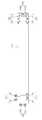
도 6은 본 고안에 의한 등기구 제1 실시예의 평면도이고, 도 7은 본 고안에 의한 등기구 제2 실시예의 평면도이며, 도 8은 본 고안에 의한 등기구 제3 실시예의 평면도이다.Fig. 6 is a plan view of the first embodiment of the lighting fixture according to the present invention, Fig. 7 is a plan view of the second embodiment of the lighting fixture according to the present invention, and Fig. 8 is a plan view of the third embodiment of the lighting fixture according to the present invention.
본 고안에 의한 등기구는 상기와 같이 구성되는 둘 이상의 엘이디모듈(100)과, 상기 엘이디모듈(100)로 직류전원을 공급하는 컨버터(200)를 포함하도록 구성된다. 이때 상기 둘 이상의 엘이디모듈(100)은 별도의 전선 없이도 전기적으로 연결 가능하며, 별도의 연결수단 없이도 기준치 이상의 결합강도를 갖도록 구조적으로 연결된다.The lamp according to the present invention is configured to include two or
즉, 어느 하나의 엘이디모듈(100) 단자홈(140)에 다른 하나의 엘이디모듈(100) 돌출단자(130)가 삽입되어, 복수 개의 엘이디모듈(100)이 일체로 결합된다. 이때 상기 컨버터(200)는 둘 이상의 엘이디모듈(100) 중 어느 하나의 엘이디모듈(100) 돌출단자(130)에 직류전원을 인가하도록 결합된다.That is, another
상기 복수 개의 엘이디모듈(100)은, 일자 형광등과 유사한 발광패턴을 갖도록 도 6에 도시된 바와 같이 길이방향으로 일렬로 연결될 수 있다. 일렬로 연결된 복수 개의 엘이디모듈(100)은 상호 통전상태가 되는바, 컨버터(200)가 어느 하나의 엘이디모듈(100)(도 6에서는 좌측 엘이디모듈(100))에만 전류를 공급하더라도 모든 엘이디모듈(100)이 발광을 하게 된다.The plurality of
또한 본 고안에 의한 등기구는, 도 7에 도시된 바와 같이 복수 개의 엘이디모듈(100)이 사각형으로 연결되거나, 도 8에 도시된 바와 같이 폭방향으로 연이어 배열되도록 연결될 수 있다.7, the plurality of
도 7에 도시된 바와 같이 복수 개의 엘이디모듈(100)이 사각형으로 연결되는 경우, 각 엘이디모듈(100)이 넓게 퍼지도록 배열되는바, 보다 넓은 공간에 빛을 고르게 조사할 수 있게 된다. 즉, 도 7에 도시된 바와 같이 복수 개의 엘이디모듈(100)이 직사각형으로 연결된 등기구는, 거실등이나 현관등과 같이 높은 조도는 필요치 아니하지만 면적이 넓은 장소에 활용될 수 있다. 본 실시예에서는 상기 복수 개의 엘이디모듈(100)이 사각형으로 배열되는 경우만을 도시하고 있으나, 본 고안에 의한 등기구는 복수 개의 엘이디모듈(100)이 어떠한 종류의 다각형을 이루도록 배열될 수 있다.As shown in FIG. 7, when the plurality of
또한 도 8에 도시된 바와 같이 복수 개의 엘이디모듈(100)이 폭방향으로 연이어 배열되면, 엘이디모듈(100)의 밀집도가 최대로 높아지므로, 단위면적 당 조사량 역시 최대로 높아진다. 따라서 도 8에 도시된 바와 같이 복수 개의 엘이디모듈(100)이 폭방향으로 연이어 연결된 등기구는, 공부방이나 작업실 등과 같이 높은 조도가 요구되는 장소에 활용될 수 있다.Also, as shown in FIG. 8, when the plurality of
이상, 본 고안을 바람직한 실시예를 사용하여 상세히 설명하였으나, 본 고안의 범위는 특정 실시예에 한정되는 것은 아니며, 첨부된 청구범위에 의하여 해석되어야 할 것이다. 또한, 이 기술분야에서 통상의 지식을 습득한 자라면, 본 고안의 범위에서 벗어나지 않으면서도 많은 수정과 변형이 가능함을 이해하여야 할 것이다.While the present invention has been described in detail with reference to the preferred embodiments thereof, the scope of the present invention is not limited to the specific embodiments but should be construed according to the appended claims. Those skilled in the art will appreciate that many modifications and variations are possible without departing from the scope of the present invention.
100 : 엘이디모듈110 : 기판
112 : 나사홀114 : 양면테이프
120 : 발광소자130 : 돌출단자
132 : 양극돌출단자134 : 음극돌출단자
140 : 단자홈142 : 양극단자홈
144 : 음극단자홈200 : 컨버터100: LED module 110: substrate
112: screw hole 114: double-sided tape
120: light emitting element 130: protruding terminal
132: positive electrode protrusion terminal 134: negative electrode protrusion terminal
140: terminal groove 142: positive terminal groove
144: cathode terminal groove 200: converter
Claims (9)
Translated fromKorean상기 기판(110)의 상면에 결합되는 발광소자(120);
상기 기판(110)의 일측에 형성되어 외부로부터 인가된 전원을 상기 발광소자(120)로 전달하는 돌출단자(130);
상기 돌출단자(130)가 끼워맞춤 방식으로 삽입될 수 있는 오목한 형상으로 형성되어, 상기 기판(110)의 타측에 구비되는 단자홈(140);
을 포함하는 것을 특징으로 하는 엘이디모듈(100).
A substrate 110 in a bar shape elongated in one direction;
A light emitting device 120 coupled to an upper surface of the substrate 110;
A protruding terminal 130 formed on one side of the substrate 110 to transmit a power applied from the outside to the light emitting device 120;
A terminal groove 140 formed on the other side of the substrate 110 and formed in a concave shape in which the protruding terminal 130 can be inserted in a fitting manner;
(100). ≪ / RTI >
상기 돌출단자(130)는 상기 기판(110)의 길이방향 일단에 형성되고,
상기 단자홈(140)은 상기 기판(110)의 길이방향 타단에 형성되는 것을 특징으로 하는 엘이디모듈(100).
The method according to claim 1,
The protruding terminal 130 is formed at one end in the longitudinal direction of the substrate 110,
Wherein the terminal groove (140) is formed at the other longitudinal end of the substrate (110).
상기 돌출단자(130)는 상기 기판(110)의 폭방향 일측면에 형성되고,
상기 단자홈(140)은 상기 기판(110)의 폭방향 타측면에 형성되는 것을 특징으로 하는 엘이디모듈(100).
The method according to claim 1,
The protruding terminal 130 is formed on one lateral side of the substrate 110,
And the terminal groove (140) is formed on the other side in the width direction of the substrate (110).
상기 돌출단자(130)는, 상기 기판(110)의 길이방향 일단과, 상기 기판(110)의 폭방향 일측면 중 상기 기판(110)의 길이방향 일측에 각각 형성되고,
상기 단자홈(140)은, 상기 기판(110)의 길이방향 타단과, 상기 기판(110)의 폭방향 일측면 중 상기 기판(110)의 길이방향 타측과, 상기 기판(110)의 폭방향 타측면 중 상기 기판(110)의 길이방향 양측에 각각 형성되는 것을 특징으로 하는 엘이디모듈(100).
The method according to claim 1,
The protruding terminals 130 are formed at one longitudinal end of the substrate 110 and one lateral side of the substrate 110 in the longitudinal direction of the substrate 110,
The terminal grooves 140 are formed in the longitudinal direction of the substrate 110 and the other longitudinal side of the substrate 110 in a widthwise direction of the substrate 110, Are formed on both sides of the side surface in the longitudinal direction of the substrate (110).
상기 돌출단자(130)는, 양극돌출단자(132)와 음극돌출단자(134)로 구성되고,
상기 단자홈(140)은, 양극단자홈(142)과 음극단자홈(144)으로 구성되며,
상기 양극돌출단자(132)는 상기 양극단자홈(142)과 전기적으로 연결되고, 상기 음극돌출단자(134)는 상기 음극단자홈(144)에 삽입되는 것을 특징으로 하는 엘이디모듈(100).
The method according to claim 1,
The protruding terminal 130 is composed of a positive electrode protruding terminal 132 and a negative electrode protruding terminal 134,
The terminal groove 140 is composed of a positive terminal groove 142 and a negative terminal groove 144,
Wherein the positive electrode protrusion terminal 132 is electrically connected to the positive electrode terminal groove 142 and the negative electrode protrusion terminal 134 is inserted into the negative electrode terminal groove 144.
상기 기판(110)에는 상하방향으로 관통하는 둘 이상의 나사홀(112)이 형성되는 것을 특징으로 하는 엘이디모듈(100).
The method according to claim 1,
Wherein at least two screw holes (112) penetrating through the substrate (110) in a vertical direction are formed on the substrate (110).
상기 기판(110)의 저면에는 양면테이프(114)가 부착되는 것을 특징으로 하는 엘이디모듈(100).
The method according to claim 1,
Wherein a double-sided tape (114) is attached to the bottom surface of the substrate (110).
어느 하나의 엘이디모듈(100) 단자홈(140)에 다른 하나의 엘이디모듈(100) 돌출단자(130)가 삽입되어, 복수 개의 엘이디모듈(100)이 일체로 결합되고,
상기 컨버터(200)는 둘 이상의 엘이디모듈(100) 중 어느 하나의 엘이디모듈(100) 돌출단자(130)에 직류전원을 인가하도록 결합되는 것을 특징으로 하는 등기구.
A plurality of LED modules (100) according to any one of claims 1 to 7; and a converter (200) for supplying DC power to the LED modules (100)
Another LED module 100 protruding terminal 130 is inserted into one of the LED module 100 terminal grooves 140 so that a plurality of LED modules 100 are integrally coupled,
Wherein the converter (200) is coupled to apply a DC power to the protruding terminal (130) of one of the two or more LED modules (100).
상기 복수 개의 엘이디모듈(100)이 일렬로 배열되거나, 다각형을 이루도록 배열되거나, 폭방향으로 연이어 배열되는 것을 특징으로 하는 등기구.The method of claim 8,
Wherein the plurality of LED modules (100) are arranged in a row, a polygonal shape, or arranged in a width direction.
Priority Applications (1)
| Application Number | Priority Date | Filing Date | Title |
|---|---|---|---|
| KR2020150006871UKR20170001527U (en) | 2015-10-22 | 2015-10-22 | Led module improved connecting structuer and lamp device using the same |
Applications Claiming Priority (1)
| Application Number | Priority Date | Filing Date | Title |
|---|---|---|---|
| KR2020150006871UKR20170001527U (en) | 2015-10-22 | 2015-10-22 | Led module improved connecting structuer and lamp device using the same |
Publications (1)
| Publication Number | Publication Date |
|---|---|
| KR20170001527Utrue KR20170001527U (en) | 2017-05-04 |
Family
ID=58716548
Family Applications (1)
| Application Number | Title | Priority Date | Filing Date |
|---|---|---|---|
| KR2020150006871UCeasedKR20170001527U (en) | 2015-10-22 | 2015-10-22 | Led module improved connecting structuer and lamp device using the same |
Country Status (1)
| Country | Link |
|---|---|
| KR (1) | KR20170001527U (en) |
Cited By (1)
| Publication number | Priority date | Publication date | Assignee | Title |
|---|---|---|---|---|
| KR20200006356A (en) | 2018-07-10 | 2020-01-20 | 김현 | electric connection device for lighting apparatus using light emitting diode |
Citations (1)
| Publication number | Priority date | Publication date | Assignee | Title |
|---|---|---|---|---|
| KR101167497B1 (en) | 2012-02-08 | 2012-07-20 | (주)윌넷 | Bar type led module and led illuminating device |
- 2015
- 2015-10-22KRKR2020150006871Upatent/KR20170001527U/ennot_activeCeased
Patent Citations (1)
| Publication number | Priority date | Publication date | Assignee | Title |
|---|---|---|---|---|
| KR101167497B1 (en) | 2012-02-08 | 2012-07-20 | (주)윌넷 | Bar type led module and led illuminating device |
Cited By (1)
| Publication number | Priority date | Publication date | Assignee | Title |
|---|---|---|---|---|
| KR20200006356A (en) | 2018-07-10 | 2020-01-20 | 김현 | electric connection device for lighting apparatus using light emitting diode |
Similar Documents
| Publication | Publication Date | Title |
|---|---|---|
| US7377669B2 (en) | LED module and system of LED modules with integral branch connectors | |
| US8632214B1 (en) | Light modules with uninterrupted arrays of LEDs | |
| JP6165832B2 (en) | Line-type lighting device (LINETYPIGHTINGGAPPPARATUS) | |
| US9696019B2 (en) | LED lighting structure | |
| US20130322082A1 (en) | Modular light emitting diode (led) lighting fixtures | |
| US20110285314A1 (en) | Linkable Linear Light Emitting Diode System | |
| KR100834973B1 (en) | LED Landscape Lighting | |
| KR200413523Y1 (en) | LED lighting | |
| US11015771B2 (en) | LED plant illumination lamp module | |
| US20190003659A1 (en) | Led lighting apparatus | |
| JP2011014317A (en) | Lighting body and lighting system | |
| CN102278628A (en) | lighting device | |
| JP2011258474A (en) | Lighting device | |
| JP2011258476A (en) | Lighting device | |
| KR20110012044U (en) | Elongate lamp with light emitting diodes | |
| JP2015069846A (en) | Light-emitting module, tube-type light-emitting lamp and lighting | |
| US20130062631A1 (en) | Light emitting structure, light emitting module, and light emitting device | |
| KR200483092Y1 (en) | Scalable LED lighting device | |
| KR20090009386U (en) | Scalable light source device using LED | |
| KR20110022262A (en) | Folding lighting | |
| KR20170001527U (en) | Led module improved connecting structuer and lamp device using the same | |
| KR100945173B1 (en) | Led lighting apparatus | |
| KR101756540B1 (en) | Lighting installation with horizontally expandable structure | |
| CN205535093U (en) | Two -sided luminous LED lamps and lanterns and advertising light boxes | |
| CN207298430U (en) | LED lighting module and lighting device |
Legal Events
| Date | Code | Title | Description |
|---|---|---|---|
| A201 | Request for examination | ||
| UA0108 | Application for utility model registration | Comment text:Application for Utility Model Registration Patent event code:UA01011R08D Patent event date:20151022 | |
| UA0201 | Request for examination | ||
| A302 | Request for accelerated examination | ||
| UA0301 | Request for accelerated examination | Comment text:[Request for Accelerated Examination] Document of Request for Examination(Accelerated Examination) Patent event date:20151023 Patent event code:UA03012R01D Comment text:Application for Utility Model Registration Patent event date:20151022 Patent event code:UA03011R01I | |
| E902 | Notification of reason for refusal | ||
| UE0902 | Notice of grounds for rejection | Comment text:Notification of reason for refusal Patent event code:UE09021S01D Patent event date:20151120 | |
| AMND | Amendment | ||
| E902 | Notification of reason for refusal | ||
| UE0902 | Notice of grounds for rejection | Comment text:Notification of reason for refusal Patent event code:UE09021S01D Patent event date:20160330 | |
| AMND | Amendment | ||
| E601 | Decision to refuse application | ||
| UE0601 | Decision on rejection of utility model registration | Comment text:Decision to Refuse Application Patent event code:UE06011S01D Patent event date:20160826 | |
| AMND | Amendment | ||
| UX0901 | Re-examination | Patent event date:20160826 Comment text:Decision to Refuse Application Patent event code:UX09011S01I Patent event date:20160530 Comment text:Amendment to Specification, etc. Patent event code:UX09012R01I Patent event date:20160119 Comment text:Amendment to Specification, etc. Patent event code:UX09012R01I | |
| UX0601 | Decision of rejection after re-examination | Patent event date:20161018 Comment text:Decision to Refuse Application Patent event code:UX06014S01D Patent event date:20160926 Comment text:Amendment to Specification, etc. Patent event code:UX06012R01I Patent event date:20160826 Comment text:Decision to Refuse Application Patent event code:UX06011S01I Patent event date:20160530 Comment text:Amendment to Specification, etc. Patent event code:UX06012R01I Patent event date:20160330 Comment text:Notification of reason for refusal Patent event code:UX06013S01I Patent event date:20160119 Comment text:Amendment to Specification, etc. Patent event code:UX06012R01I Patent event date:20151120 Comment text:Notification of reason for refusal Patent event code:UX06013S01I | |
| X601 | Decision of rejection after re-examination | ||
| J201 | Request for trial against refusal decision | Free format text:TRIAL NUMBER: 2016101006486; TRIAL AGAINST DECISION OF REJECTION FOR APPEAL AGAINST DECISION TO DECLINE REFUSAL | |
| UJ0201 | Trial against decision of rejection | Patent event code:UJ02012R01D Comment text:Request for Trial against Decision on Refusal Patent event date:20161116 Patent event code:UJ02011S01I Comment text:Decision to Refuse Application Patent event date:20161018 Patent event code:UJ02011S01I Comment text:Decision to Refuse Application Patent event date:20160826 Appeal identifier:2016101006486 Request date:20161116 Appeal kind category:Appeal against decision to decline refusal | |
| UG1501 | Laying open of application | ||
| J301 | Trial decision | Free format text:TRIAL NUMBER: 2016101006486; TRIAL DECISION FOR APPEAL AGAINST DECISION TO DECLINE REFUSAL REQUESTED 20161116 Effective date:20180614 | |
| UJ1301 | Trial decision | Patent event date:20180614 Patent event code:UJ13011S01D Comment text:Trial Decision on Objection to Decision on Refusal Appeal identifier:2016101006486 Appeal kind category:Appeal against decision to decline refusal Decision date:20180614 Request date:20161116 |