KR20160148140A - A Portable Ultra-Violet Light Sterilizer - Google Patents
A Portable Ultra-Violet Light SterilizerDownload PDFInfo
- Publication number
- KR20160148140A KR20160148140AKR1020150084560AKR20150084560AKR20160148140AKR 20160148140 AKR20160148140 AKR 20160148140AKR 1020150084560 AKR1020150084560 AKR 1020150084560AKR 20150084560 AKR20150084560 AKR 20150084560AKR 20160148140 AKR20160148140 AKR 20160148140A
- Authority
- KR
- South Korea
- Prior art keywords
- led
- portable
- ultraviolet
- housing
- connector
- Prior art date
- Legal status (The legal status is an assumption and is not a legal conclusion. Google has not performed a legal analysis and makes no representation as to the accuracy of the status listed.)
- Withdrawn
Links
- 239000000758substrateSubstances0.000claimsabstractdescription30
- 238000009792diffusion processMethods0.000claimsabstractdescription16
- 230000000249desinfective effectEffects0.000claimsdescription55
- 238000000034methodMethods0.000claimsdescription20
- 238000004659sterilization and disinfectionMethods0.000claimsdescription8
- 208000015181infectious diseaseDiseases0.000claimsdescription4
- 230000002458infectious effectEffects0.000claimsdescription2
- 230000001954sterilising effectEffects0.000abstractdescription40
- 241000700605VirusesSpecies0.000description4
- 241000894006BacteriaSpecies0.000description3
- 230000000694effectsEffects0.000description3
- 238000005406washingMethods0.000description3
- 208000035473Communicable diseaseDiseases0.000description2
- 125000002066L-histidyl groupChemical group[H]N1C([H])=NC(C([H])([H])[C@](C(=O)[*])([H])N([H])[H])=C1[H]0.000description2
- 230000001580bacterial effectEffects0.000description2
- 201000010099diseaseDiseases0.000description2
- 208000037265diseases, disorders, signs and symptomsDiseases0.000description2
- 244000005700microbiomeSpecies0.000description2
- 230000005855radiationEffects0.000description2
- 229960005486vaccineDrugs0.000description2
- 208000035143Bacterial infectionDiseases0.000description1
- 206010011224CoughDiseases0.000description1
- 241000282412HomoSpecies0.000description1
- 208000036142Viral infectionDiseases0.000description1
- 230000002411adverseEffects0.000description1
- 230000000844anti-bacterial effectEffects0.000description1
- 208000022362bacterial infectious diseaseDiseases0.000description1
- 239000003814drugSubstances0.000description1
- 239000012530fluidSubstances0.000description1
- 238000004519manufacturing processMethods0.000description1
- 239000002773nucleotideSubstances0.000description1
- 125000003729nucleotide groupChemical group0.000description1
- 230000003449preventive effectEffects0.000description1
- 238000001228spectrumMethods0.000description1
- 230000001225therapeutic effectEffects0.000description1
- 230000009466transformationEffects0.000description1
- 238000002604ultrasonographyMethods0.000description1
- 230000009385viral infectionEffects0.000description1
Images


Classifications
- A—HUMAN NECESSITIES
- A61—MEDICAL OR VETERINARY SCIENCE; HYGIENE
- A61L—METHODS OR APPARATUS FOR STERILISING MATERIALS OR OBJECTS IN GENERAL; DISINFECTION, STERILISATION OR DEODORISATION OF AIR; CHEMICAL ASPECTS OF BANDAGES, DRESSINGS, ABSORBENT PADS OR SURGICAL ARTICLES; MATERIALS FOR BANDAGES, DRESSINGS, ABSORBENT PADS OR SURGICAL ARTICLES
- A61L2/00—Methods or apparatus for disinfecting or sterilising materials or objects other than foodstuffs or contact lenses; Accessories therefor
- A61L2/02—Methods or apparatus for disinfecting or sterilising materials or objects other than foodstuffs or contact lenses; Accessories therefor using physical phenomena
- A61L2/08—Radiation
- A61L2/10—Ultraviolet radiation
- A—HUMAN NECESSITIES
- A61—MEDICAL OR VETERINARY SCIENCE; HYGIENE
- A61L—METHODS OR APPARATUS FOR STERILISING MATERIALS OR OBJECTS IN GENERAL; DISINFECTION, STERILISATION OR DEODORISATION OF AIR; CHEMICAL ASPECTS OF BANDAGES, DRESSINGS, ABSORBENT PADS OR SURGICAL ARTICLES; MATERIALS FOR BANDAGES, DRESSINGS, ABSORBENT PADS OR SURGICAL ARTICLES
- A61L2202/00—Aspects relating to methods or apparatus for disinfecting or sterilising materials or objects
- A61L2202/10—Apparatus features
- A61L2202/16—Mobile applications, e.g. portable devices, trailers, devices mounted on vehicles
Landscapes
- Health & Medical Sciences (AREA)
- Epidemiology (AREA)
- Life Sciences & Earth Sciences (AREA)
- Animal Behavior & Ethology (AREA)
- General Health & Medical Sciences (AREA)
- Public Health (AREA)
- Veterinary Medicine (AREA)
- Apparatus For Disinfection Or Sterilisation (AREA)
Abstract
Translated fromKoreanDescription
Translated fromKorean본 발명은 자외선 살균 장치에 관한 것으로, 보다 상세하게는 휴대가 간편하고 언제 어디서나 즉시 사용할 수 있으며, 사용 방법이 매우 간편한 휴대용 자외선 살균 장치에 관한 것이다.More particularly, the present invention relates to a portable ultraviolet sterilizing apparatus which is easy to carry, which can be readily used anytime and anywhere, and which is very easy to use.
의학과 약학이 발전함에 따라 인간과 바이러스의 싸움은 계속되고 있다. 바이러스는 끊임없이 변이하여 백신의 위협으로부터 벗어나려고 하고 있으며, 인간은 바이러스를 정복하기 위해 지속적으로 백신과 같은 예방수단이나 치료수단을 강구하고 있다.As medicine and pharmacy develop, the fight against human and virus continues. Viruses are constantly changing and trying to escape the threat of vaccines, and humans are constantly looking for preventive or therapeutic means such as vaccines to conquer the virus.
전염성이 매우 강한 질병은 공기를 통해서도 전염이 되기 때문에 매우 심각한 수준이지만, 대부분의 전염성 질병은 사람의 손을 통해 감염된다. 즉 감염된 사람이 기침을 하여 토출된 체액이 직접 다른 사람에게 도달하거나, 물건에 도달한 상태에서 다른 사람이 이러한 물건을 손으로 만진 후, 다시 그 손으로 얼굴 등을 만져 감염되는 경로가 일반적이다. 그래서 손을 깨끗이 자주 씻으면 대부분의 질병은 예방할 수 있다고 한다.Most highly contagious diseases are transmitted through the air, so they are very serious, but most infectious diseases are transmitted through human hands. In other words, when the infected person coughs and the discharged fluid reaches the other person directly, or when the person reaches the object, the other person touches the object with his hand and then touches his / her face with his / her hand again. Therefore, most of the disease can be prevented by washing hands frequently.
하지만 손을 씻는 세면 시설이 어디에서나 접근 가능한 것도 아니고, 세면 시설이 있다고 한들, 많은 사람이 공용으로 사용하여 반드시 깨끗하리라는 보장도 없다. 또한 가사 이러한 세면 시설이 잘 갖추어져 있고, 위생관리도 잘 된다고 하더라도, 감염된 환자가 만진 문고리나 엘리베이터 버튼과 같은 물건은 손을 씻는다고 해서 즉시 해결되는 사항도 아니다. 그래서 전염병이 유행할 때, 사람들은 외출하기를 꺼리고, 심지어 여러 사람들이 만지는 물건을 만질 때 굉장히 꺼림직한 기분을 느끼게 된다.However, hand washing facilities are not accessible anywhere, and there is no guarantee that many people will use it publicly, even if it is a toilet. Housekeeping Even if these toilet facilities are well equipped and sanitary control is good, things such as baggage or elevator buttons touched by an infected patient are not immediately resolved by washing their hands. So when the epidemic is in vogue, people are reluctant to go out, and even feel very guilty when they touch things that people touch.
본 발명은 상기한 바와 같은 문제점을 해결하기 위해 안출된 것으로, 언제 어디서나 간편하게 소독을 실시할 수 있는 휴대용 자외선 살균 장치를 제공하는 것을 목적으로 한다.Disclosure of Invention Technical Problem [8] Accordingly, the present invention has been made keeping in mind the above problems occurring in the prior art, and an object of the present invention is to provide a portable ultraviolet sterilizing device capable of easily disinfecting anytime and anywhere.
상술한 과제를 해결하기 위해 본 발명은, UV LED(12)가 실장된 기판(10); 상기 기판(10)을 수용하는 하우징(30); 상기 UV LED(12)에서 조사되는 자외선의 확산각을 조절하는 옵틱(20); 및 상기 기판(10)과 전기적으로 연결되며, 외부로부터 전원을 공급받는 경로가 되는 커넥터(40);를 포함하는 휴대용 자외선 소독 장치를 제공한다.In order to solve the above-described problems, the present invention provides a light emitting device comprising: a substrate (10) on which a UV LED (12) is mounted; A housing (30) for receiving the substrate (10); An optic 20 for adjusting a diffusion angle of ultraviolet light emitted from the
상기 커넥터(40)는, 상기 기판(10)을 기준으로 상기 UV LED(12)의 자외선 조사 방향의 반대방향 또는 UV LED(12)의 자외선 조사 방향의 중심방향과 수직한 방향으로 연장 형성된 수형 3.5파이 이어폰 커넥터일 수 있다.The
상기 커넥터(40)는, 적어도 상기 기판(10)을 기준으로 상기 UV LED(12)의 자외선 조사 방향의 반대방향과 UV LED(12)의 자외선 조사 방향의 중심방향과 수직한 방향 사이에서 회전 가능하다.The
상기 기판(10) 상의 UV LED(12) 부근에는 가시광 LED(14)가 실장될 수 있다.A
상기 옵틱(20)은 상기 UV LED(12)에서 조사되는 자외선과, 상기 가시광 LED(14)에서 조사되는 가시광선의 확산각을 모두 제어할 수 있다.The optic 20 can control the diffusing angle of the ultraviolet light emitted from the
상기 옵틱(20)은 확산각을 더 넓게 하는 광각 옵틱(21)과 확산각을 더 좁게 하는 협각 옵틱(22) 중 적어도 어느 하나를 포함할 수 있다.The optic 20 may include at least one of a wide-angle optic 21 that widens the diffusion angle and a narrow angle optic 22 that narrows the diffusion angle.
상기 옵틱(20)은 착탈 가능하게 설치될 수 있다.The optic 20 may be removably installed.
상기 UV LED(12)와 가시광 LED(14) 중 적어도 어느 하나의 LED 전방에는 보정 옵틱(23,24)이 설치될 수 있다.At least one of the
상기 UV LED(12)와 가시광 LED(14) 중 어느 한 종류의 LED를 중심으로 하여 그 둘레에 다른 한 종류의 LED가 복수 개 방사상으로 실장될 수 있다.A plurality of LEDs of different types can be radially mounted around the LEDs of any one of the
또한 상술한 과제를 해결하기 위해 본 발명은, 상기 휴대용 자외선 소독 장치가 설치된 휴대용 단말을 제공한다.Further, in order to solve the above problems, the present invention provides a portable terminal equipped with the portable ultraviolet disinfecting device.
상기 휴대용 단말에는 상기 휴대용 자외선 소독 장치에 공급하는 전원의 공급 여부와, 전원의 공급 시간을 제어하는 애플리케이션이 설치될 수 있다.The portable terminal may be provided with an application for controlling the supply of power to the portable ultraviolet disinfecting device and the supply time of the power.
상기 애플리케이션은 휴대용 단말의 위치 정보와, 서버로부터 전송되는 감염 위험 지역에 대한 정보를 비교하여 상기 휴대용 자외선 소독 장치에 공급되는 전원을 제어할 수 있다.The application may control the power supplied to the portable ultraviolet disinfector by comparing the information of the location of the portable terminal with the information of the infectious danger area transmitted from the server.
상기 애플리케이션은 휴대용 단말의 자세 정보가 소정의 자세에 해당하는 경우 상기 휴대용 자외선 소독 장치에 공급되는 전원을 제어할 수 있다.The application can control the power supplied to the portable ultraviolet disinfecting device when the attitude information of the portable terminal corresponds to a predetermined attitude.
상기 애플리케이션은 휴대용 단말에 설치된 카메라모듈에서 촬영되는 화각을 소프트웨어적으로 제어하여 상기 휴대용 자외선 소독 장치의 자외선 확산각과 일치시킬 수 있다.The application may be controlled by software in an angle of view photographed by a camera module installed in the portable terminal to coincide with the ultraviolet ray diffusion angle of the portable ultraviolet disinfecting device.
상기 애플리케이션은 휴대용 단말에 설치된 카메라모듈에서 촬영되는 영상에서 특정 형상을 인지한 경우 상기 휴대용 자외선 소독 장치에 공급되는 전원을 제어할 수 있다.The application may control the power supplied to the portable ultraviolet disinfecting device when recognizing a specific shape in an image photographed by a camera module installed in the portable terminal.
또한 상술한 과제를 해결하기 위해 본 발명은, 상기 휴대용 자외선 소독 장치가 설치된 USB 커넥터로서, 상기 USB 커넥터(60)의 일측 단부에는 상기 휴대용 자외선 소독 장치가 끼워지는 암형 커넥터부(61)가 구비되고, 상기 USB 커넥터의 타측 단부에는 전원을 공급할 수 있는 암형 USB 단자에 끼워지는 수형 USB 단자(62)가 구비되는 USB 커넥터를 제공한다.According to another aspect of the present invention, there is provided a USB connector provided with the portable ultraviolet disinfecting device, wherein a female connector portion (61) for inserting the portable ultraviolet disinfecting device is provided at one end of the USB connector And a male
상기 USB 커넥터에는 상기 UV LED에 공급되는 전원의 온오프를 제어하는 스위치(611)가 설치될 수 있다.The USB connector may be provided with a
또한 상술한 과제를 해결하기 위해 본 발명은, 상기 휴대용 자외선 소독 장치가 설치된 배터리팩으로서, 상기 휴대용 자외선 살균 장치의 커넥터(40)와 연결되는 암형 커넥터(41)를 구비하는 배터리팩을 제공한다.In order to solve the above-described problems, the present invention provides a battery pack having the portable ultraviolet disinfecting device, the battery pack including a female connector (41) connected to the connector (40) of the portable ultraviolet sterilizer.
상기 배터리팩은 근거리통신모듈을 더 구비할 수 있다.The battery pack may further include a short-range communication module.
또한 상술한 과제를 해결하기 위해 본 발명은, UV LED(12)가 실장된 기판(10); 상기 기판(10)을 수용하는 하우징(30); 상기 UV LED(12)에서 조사되는 자외선의 확산각을 조절하는 옵틱(20); 및 상기 기판(10)과 전기적으로 연결되며, 상기 하우징(30) 내에 수용되어 상기 UV LED(12)에 전원을 공급하는 배터리(75);를 포함하는 휴대용 자외선 소독 장치를 제공한다.Further, in order to solve the above-described problems, the present invention provides a light emitting device comprising: a substrate on which a UV LED is mounted; A housing (30) for receiving the substrate (10); An optic 20 for adjusting a diffusion angle of ultraviolet light emitted from the
상기 휴대용 자외선 소독 장치는 근거리통신모듈을 더 구비할 수 있다.The portable ultraviolet disinfecting apparatus may further include a short range communication module.
상기 하우징은 단면적이 다른 동축의 하우징이 서로 중첩되어 전체적인 길이가 축소되고, 적어도 하나의 하우징이 다른 하우징에 대해 인출되었을 때 전체적인 길이가 늘어나는 구조이며, 적어도 하나의 하우징이 다른 하우징에 대해 인출되었을 때 UV LED(12)가 외부로 노출될 수 있다.The housing has a structure in which coaxial housings having different cross-sectional areas are overlapped with each other to reduce the overall length, and the overall length is increased when at least one housing is drawn out to the other housing. When at least one housing is drawn out to the other housing The
상기 하우징은 힌지점을 기준으로 펼쳐지거나 접혀지는 적어도 2개의 분할된 하우징을 구비하며, 상기 힌지점을 기준으로 분할된 하우징이 펼쳐졌을 때 UV LED(12)가 외부로 노출될 수 있다.The housing has at least two divided housings that are unfolded or folded with respect to a hinge point, and the
한편 상기 UV LED(12)에서 조사되는 자외선의 피크파장은 240nm~280nm내에 존재할 수 있다.On the other hand, the peak wavelength of ultraviolet light emitted from the
본 발명에 의하면, 언제 어디서나 쉽고 간편하게 자외선으로 손에 대한 소독은 물론 손으로 만질 수밖에 없는 물건에 대해서도 소독을 할 수 있어 매우 위생적이다.According to the present invention, it is very hygienic to disinfect the hands, which is inevitably touched by hand, as well as disinfecting the hands with ultraviolet rays easily anytime and anywhere.
상술한 효과와 더불어 본 발명의 구체적인 효과는 이하 발명을 실시하기 위한 구체적인 사항을 설명하면서 함께 기술한다.The above and other objects, features and advantages of the present invention will be more apparent from the following detailed description taken in conjunction with the accompanying drawings, in which: FIG.
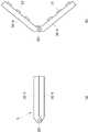
도 1은 본 발명에 따른 휴대용 자외선 살균 장치의 일 실시예의 사시도,
도 2는 도 1의 휴대용 자외선 살균 장치의 측면도,
도 3 내지 도 7은 본 발명의 휴대용 자외선 살균 장치의 UV LED와 가시광 LED, 그리고 옵틱의 구조의 다양한 실시예를 나타낸 도면,
도 8은 도 1의 휴대용 자외선 살균 장치를 스마트폰에 설치하는 형태를 나타낸 정면도,
도 9는 도 8의 스마트폰의 디스플레이를 나타낸 도면,
도 10은 다른 형태의 휴대용 자외선 살균 장치를 스마트폰에 설치하는 형태를 나타낸 측면도,
도 11은 도 1의 휴대용 자외선 살균 장치를 USB 커넥터에 연결한 상태를 나타낸 도면,
도 12는 도 1의 휴대용 자외선 살균 장치를 배터리팩에 연결하는 상태를 나타낸 도면, 그리고,
도 13 내지 도 15는 본 발명에 따른 휴대용 자외선 살균 장치의 다른 일 실시예들을 나타낸 도면이다.1 is a perspective view of an embodiment of a portable ultraviolet sterilizing apparatus according to the present invention,
Fig. 2 is a side view of the portable ultraviolet sterilizing apparatus of Fig. 1,
3 to 7 are views showing various embodiments of the structure of the UV LED, the visible light LED, and the optic of the portable ultraviolet sterilizing apparatus of the present invention,
FIG. 8 is a front view showing a mode in which the portable ultraviolet sterilizing apparatus of FIG. 1 is installed in a smartphone;
9 shows a display of the smartphone of Fig. 8,
10 is a side view showing a mode in which another type of portable ultraviolet sterilizing device is installed in a smartphone,
FIG. 11 is a view showing a state in which the portable ultraviolet sterilizing apparatus of FIG. 1 is connected to a USB connector,
FIG. 12 is a view illustrating a state in which the portable ultraviolet sterilizing device of FIG. 1 is connected to a battery pack,
13 to 15 are views showing another embodiment of the portable ultraviolet sterilizing apparatus according to the present invention.
이하, 본 발명의 바람직한 실시예를 첨부한 도면을 참조로 하여 상세히 설명한다.Hereinafter, preferred embodiments of the present invention will be described in detail with reference to the accompanying drawings.
본 발명은 이하에서 개시되는 실시예에 한정되는 것이 아니라 서로 다른 다양한 형태로 구현될 수 있으며, 단지 본 실시예는 본 발명의 개시가 완전하도록 하며 통상의 지식을 가진 자에게 발명의 범주를 완전하게 알려주기 위하여 제공되는 것이다.It is to be understood that the present invention is not limited to the disclosed embodiments, but may be embodied in many different forms and should not be construed as limited to the embodiments set forth herein. Rather, these embodiments are provided so that this disclosure will be thorough and complete, It is provided to inform.
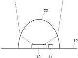
도 1은 본 발명에 따른 휴대용 자외선 살균 장치의 일 실시예의 사시도, 도 2는 도 1의 휴대용 자외선 살균 장치의 측면도, 그리고 도 3 내지 도 7은 본 발명의 휴대용 자외선 살균 장치의 UV LED와 가시광 LED, 그리고 옵틱의 구조의 다양한 실시예를 나타낸 도면이다.FIG. 1 is a perspective view of an embodiment of a portable ultraviolet sterilizing apparatus according to the present invention, FIG. 2 is a side view of the portable ultraviolet sterilizing apparatus of FIG. 1, and FIGS. And various embodiments of the structure of the optics.
본 발명의 휴대용 자외선 소독 장치는 각 구성을 수용하는 하우징(30)을 포함한다. 하우징(30) 내에는 UV LED(12)가 실장된 기판(10)이 설치되어 있다. 기판(10)의 상면에는 UV LED(12)가 실장되어 있어서 기판에 대해 상방으로 자외선을 조사할 수 있다. UV LED(12)는 칩 형태일 수 있으며 그 제조방법은 특별히 한정되지 않는다.The portable ultraviolet disinfecting apparatus of the present invention includes a
기판에는 커넥터(40)가 전기적으로 연결되어 있다. 커넥터(40)는 도 1과 도 2에 도시된 바와 같이 UV LED가 실장된 면의 반대 방향으로 연장 형성된 수형 3.5파이 이어폰 커넥터 형태로 이루어져 있다. 휴대용 자외선 소독 장치가 이러한 형태로 이루어져 있으면 도 8에 도시된 바와 같이 스마트폰과 같은 휴대용 단말장치에 끼워 전원을 공급받을 수 있다. 즉 커넥터(40)는 외부로부터 UV LED(12)에 전원을 공급하는 통로가 된다.A connector (40) is electrically connected to the substrate. The
한편 기판(10) 상에는 가시광 LED(14)가 추가로 실장되어 있다. UV LED(12)에서 조사되는 자외선은 눈에 띄지 않는데, 특히 소독 효과가 뛰어난 UVC 파장대의 자외선은 육안으로 확인하기 어렵다.On the other hand, a
UVC 파장 영역은 대략 200~280nm인데, 이 파장 영역의 자외선이 살균 작용을 하는 이유는, 미생물이나 균의 DNA 내지 RNA의 뉴클레오타이드가 자외선의 200~300nm 파장을 흡수하고, 흡수된 자외선은 핵산의 피리미딘에 6 종류의 손상을 입혀 미생물이나 세균의 복제를 불가능하게 만들기 때문이다. 따라서 인체도 UVC에 노출되면 좋지 않은 영향을 받을 수 있다. 다만 세균이나 바이러스의 경우 미량의 UVC 조사량에도 치명적인 영향을 받는 반면, 이 정도의 UVC 조사량은 인체에 별다른 영향을 미치지 않는다. 하지만 그렇다 하더라도 여전히 인체에 조사되는 UVC의 조사량을 제어할 필요가 있다.The UVC wavelength range is approximately 200 to 280 nm. The ultraviolet rays of this wavelength range are sterilized because nucleotides of DNA or RNA of microorganisms or bacteria absorb the wavelength of 200 to 300 nm of ultraviolet rays, This is because it damages six kinds of microdines and makes it impossible to reproduce microorganisms or bacteria. Therefore, exposure of the human body to UVC may be adversely affected. However, while bacterial or viral infections are also severely affected by trace amounts of UVC radiation, this amount of UVC radiation has little effect on the human body. However, there is still a need to control the dose of UVC that is irradiated to the body.
이에 본 발명에서는, UV LED(12) 근방에 가시광 LED(14)를 설치하여, UV LED에 전원이 공급될 때 가시광 LED(14)에도 전원이 공급되도록 함으로써, 육안으로 가시광 LED(14)의 점등 상태를 확인함으로써 UV LED(12)의 점등 여부를 직관적으로 판단할 수 있도록 하였다.In the present invention, the
또한 본 발명은 이에서 더 나아가, 육안으로 UV LED(12)의 작동 여부는 물론 자외선이 조사되는 영역도 육안으로 확인할 수 있도록 하였다. 이를 위해 본 발명에서는 UV LED(12)의 근방에 가시광 LED(14)을 함께 실장하고, UV LED에서 조사되는 자외선과, 가시광 LED에서 조사되는 가시광선의 확산각을 최대한 일치시켜 육안으로 가시광의 조사 영역을 확인함으로써 해당 영역에 자외선이 조사됨을 직관적으로 파악할 수 있도록 하였다. 이러한 가시광 LED 역시 약간 푸른 색이 돌아 육안으로 확인 가능한 근자외선을 조사하도록 구성할 수 있다.In addition, the present invention allows the naked eye to visually confirm whether the
UV LED(12)의 전방에는 UV LED(12)로부터 조사되는 광의 확산각을 조절하는 옵틱(20)이 마련되어 있다.An optic 20 for adjusting the diffusion angle of the light emitted from the
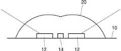
도 3을 참조하면, 일실시예로서 광각 옵틱(21)이 UV LED(12)의 전방에 설치될 수 있다. 이러한 실시예에 의하면 넓은 면적의 피소독면적을 커버할 수 있다. 또한 UV LED(12)의 바로 옆에는 가시광 LED(14)가 실장되어 있어 자외선과 거의 일치하는 가시광선을 조사하도록 할 수 있다.Referring to FIG. 3, the wide-
도 4를 참조하면, 다른 일실시예로서 협각 옵틱(22)이 UV LED(12)의 전방에 설치될 수 있다. 이러한 실시예에 의하면 좁은 면적의 피소독면적에 보다 강하게 자외선을 집중적으로 조사할 수 있다. UV LED(12)의 바로 옆에는 가시광 LED(14)가 실장되어 있어 자외선과 거의 일치하는 가시광선을 조사하도록 할 수 있다.Referring to FIG. 4, as another embodiment, the
이러한 광각 옵틱(21)과 협각 옵틱(22)은 하우징(30)에 대해 착탈 가능하게 설치될 수 있다. 따라서 사용 환경이나 필요에 따라 적절한 형태의 옵틱을 취사 사용하는 것이 가능하다.The wide-
앞서 도 3과 도 4의 실시예에 따르면, UV LED(12)와 가시광 LED(14) 서로 가까이 실장되어 있으므로, 자외선이 조사되는 영역과 가시광선이 조사되는 영역은 대체적으로 일치한다. 하지만 두 종류의 LED(12,14)의 위치가 서로 완전히 중첩되지는 아니하므로 자외선과 가시광선이 각각 조사되는 영역에는 엄연히 차이가 발생하게 된다. 또한 자외선과 가시광선은 파장이 서로 상이하므로 굴절율에도 차이가 있다. 따라서 두 종류의 LED(12,14)의 위치를 서로 완전히 중첩시킨다 하더라도 자외선과 가시광선이 각각 조사되는 영역에는 차이가 발생할 수밖에 없다.3 and 4, since the
이에 본 발명은, 도 5에 도시된 바와 같이 UV LED(12)의 전방에 자외선 보정 옵틱(23)을 설치하고, 가시광 LED(14)의 전방에 가시광선 보정 옵틱(24)을 설치하였다. 이러한 보정 옵틱(23,24)의 형상을 적절히 설계함으로써 두 LED(12,14)의 위치 차이에 의한 조사 영역의 차이와, 두 LED에서 각각 조사되는 자외선과 가시광선의 굴절율의 차이에 의해 발생하는 조사 영역의 차이를 최대한 보정할 수 있다. 도 5에서는 두 LED(12,14) 전방에 모두 보정 옵틱(23,24)이 설치된 예를 도시하였으나, 두 LED 중 어느 하나의 LED 전방에만 보정 옵틱을 설치하더라도 자외선 조사 영역과 가시광선 조사 영역을 일치시키는 것이 가능할 것이다.5, the ultraviolet
보정 옵틱(23,24)의 전방에는 보정 옵틱을 투과한 자외선과 가시광선의 확산각을 모두 제어하는 옵틱(20)이 설치될 수 있다. 이러한 옵틱은 광각 옵틱(21)이거나 협각 옵틱(22)일 수 있다.An optic 20 for controlling both the diffusing angle of the ultraviolet ray and the visible ray transmitted through the correction optic can be provided in front of the
이와 달리 보정 옵틱(23,24)만으로 자외선과 가시광선의 확산각을 개별적으로 제어하는 것도 가능하다. 즉 도 5에서 옵틱(20)이 생략된 상태에서, 보정 옵틱(23,24)으로 자외선과 가시광선의 확산각을 각각 개별적으로 제어하여 조사 영역을 일치시킬 수도 있다.Alternatively, it is also possible to individually control the diffusing angles of the ultraviolet ray and the visible ray with the
앞서 실시예들에서는 자외선의 조사 영역을 가시광선의 조사 영역과 최대한 일치시켜 육안으로 자외선의 조사 영역을 확인할 수 있는 구조에 대해 설명하였으나, 도 6과 같이 가시광 LED(14)를 옵틱(20) 외측에 두어 가시광 LED(14)의 점등 여부를 육안으로 확인하여 자외선 LED(12)의 작동 여부를 확인할 수 있도록 보다 간단하게 구성할 수 있음은 물론이다.In the above embodiments, the structure in which the irradiation region of the ultraviolet ray is maximally matched with the irradiation region of the visible ray to visually confirm the irradiation region of the ultraviolet ray has been described. However, as shown in FIG. 6, It is needless to say that it is possible to simplify the configuration so as to confirm whether the
다음으로는 도 7에 도시된 바와 같이 UV LED(12)가 가시광 LED(14) 둘레에 방사상으로 위치하도록 하여 두 광의 광원 중심이 일치하도록 구성하거나, 반대로 UV LED(12) 둘레에 가시광 LED(14)가 방사상으로 위치하도록 하여 두 광의 광원 중심이 일치하도록 구성한 뒤(미도시), 자외선이나 가시광선 파장의 굴절율에 대응하여 두 광선의 확산각을 일치시킬 수 있는 형상의 옵틱(20)을 설치함으로써 두 광선의 조사 영역을 일치시키는 것 역시 가능하다.Next, as shown in FIG. 7, the
다음으로는 이러한 휴대용 자외선 소독 장치의 사용 예에 대해 설명한다.Next, an example of using such portable ultraviolet disinfecting apparatus will be described.
도 8은 도 1의 휴대용 자외선 살균 장치를 스마트폰에 설치하는 형태를 나타낸 정면도이고, 도 9는 도 8의 스마트폰의 디스플레이를 나타낸 도면이며, 도 10은 다른 형태의 휴대용 자외선 살균 장치를 스마트폰에 설치하는 형태를 나타낸 측면도이다.Fig. 8 is a front view showing a state in which the portable ultraviolet sterilizing apparatus of Fig. 1 is installed in a smart phone, Fig. 9 is a view showing a display of the smart phone of Fig. 8, As shown in Fig.
도 8을 참조하면, 휴대용 자외선 소독 장치(1)의 커넥터(40)는 수형 3.5파이 이어폰 커넥터로서, 암형 3.5파이 이어폰 커넥터를 구비하는 스마트폰 등의 휴대용 단말(50)에 결합되어 사용될 수 있다. 이러한 사용 예에 따르면, 휴대용 자외선 소독 장치(1)는 커넥터(40)를 통해 휴대용 단말(50)의 전원을 공급받을 수 있다.Referring to FIG. 8, the
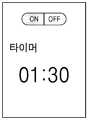
휴대용 단말(50)에는 암형 커넥터에 끼워진 휴대용 자외선 소독 장치(1)에 공급되는 전원을 제어하는 어플리케이션이 설치되어 있다. 가령 도 9와 같이 휴대용 단말의 터치 디스플레이를 통해 전원의 공급을 제어하는 온오프 스위치와, 전원의 공급 시간을 표시하는 타이머가 도시되고, 사용자가 터치 동작을 통해 스위치 온을 누르면 소독에 필요한 시간만큼 타이머가 작동하여 휴대용 자외선 소독 장치(1)에 전원을 공급할 수 있다. 이처럼 휴대용 단말의 터치패드를 통해 구동을 제어하고, 디스플레이를 통해 구동 여부와 구동 시간 등을 표시하는 것이 가능하다. 이 외에도 휴대용 단말의 하드웨어 버튼인 전원 버튼이나 볼륨 버튼을 조작하여 휴대용 자외선 소독 장치(1)에 공급되는 전원을 제어하도록 할 수 있음은 물론이다.The
휴대용 단말(50)에 휴대용 자외선 소독 장치(1)를 설치하여 사용하면, 소독 장치(1)가 작아 파지하기 어렵다 하더라도, 휴대용 단말(50)을 파지함으로써 소독 장치(1)를 파지하는 것과 같은 효과를 가져오므로 사용하기가 매우 편리하다.Even if the disinfecting
또한 상기 애플리케이션은 휴대용 단말(50)의 위치 측정 센서(GPS) 등으로부터 휴대용 단말(50)의 위치를 파악하고, 서버에서 상기 휴대용 단말(50)로 전송되는 전염병 등의 감염 위험 지역에 대한 정보를 비교하여, 휴대용 단말(50)의 위치가 감염 위험 지역 내에 있을 때 경고음을 송출하고 소독 장치(1)를 제어하는 애플리케이션을 실행시킬 수 있으며, 나아가 소독 장치에 전원을 공급하여 자외선이 조사되도록 제어할 수 있다.The application also detects the location of the portable terminal 50 from a position measuring sensor (GPS) or the like of the
또한 상기 애플리케이션은 휴대용 단말(50)의 자이로센서 등으로부터 휴대용 단말(50)의 자세를 인지하고, 자세가 특정 자세에 해당할 경우 상기 휴대용 자외선 소독 장치에 공급되는 전원을 제어하도록 할 수 있다. 가령 휴대용 단말(50)에 있어서 휴대용 자외선 소독 장치(1)가 끼워진 부분이 하향하는 자세임이 파악된 경우 휴대용 자외선 소독 장치(1)에 전원을 공급하도록 제어할 수 있다.In addition, the application can recognize the posture of the portable terminal 50 from a gyro sensor or the like of the
도 10은 앞서 설명한 휴대용 자외선 소독 장치(1)와는 다소 차이가 있는 휴대용 자외선 소독 장치(2)와, 그것이 휴대용 단말(50)에 설치되는 구조를 나타낸다. 앞서 설명한 휴대용 자외선 소독 장치(1)에 대해 휴대용 자외선 소독 장치(2)는 커넥터(40)의 방향의 자외선의 조사 방향과 수직을 이룬다는 점에 차이가 있다. 도 10을 참조하면, 휴대용 자외선 소독 장치(2)의 자외선 조사방향은 스마트폰(50)의 정면 또는 후면 방향과 일치하도록 설치할 수 있다. 또한 스마트폰(50)의 정면 또는 후면에는 카메라모듈(52)이 설치되어 있는데, 사용자는 카메라모듈(52)이 바라보는 방향과 휴대용 자외선 소독 장치(2)의 UV LED(12)가 바라보는 방향이 서로 일치하도록 휴대용 자외선 소독 장치(2)를 설치할 수 있다.10 shows a structure of a portable
스마트폰(50)에 설치된 애플리케이션은 상기 카메라모듈(52) 역시 제어할 수 있다. 상기 애플리케이션은 스마트폰(50)의 기종 등을 파악하는 방법으로 스마트폰(50)에 설치된 카메라모듈(52)의 화각 정보를 파악하고, 이를 휴대용 자외선 소독 장치(2)에서 조사되는 자외선의 확산각과 대비한 후, 카메라모듈(52)의 화각이 자외선의 확산각과 일치하도록 카메라모듈(52)의 촬영 영역을 소프트웨어적으로 처리하여 디스플레이에 도시할 수 있다. 따라서 사용자는 디스플레이에 표시되는 촬영 영역을 보며 자외선의 조사 영역을 직관적으로 파악할 수 있다.The application installed in the
또한 애플리케이션은 스마트폰(50)에 설치된 작동표시등이나 디스플레이에 UV LED(12)의 작동 여부를 표시할 수 있다. 가령 애플리케이션은 UV LED(12)가 점등된 경우 화면 상에 보여지는 카메라모듈의 촬영 영상을 파란색 계열로만 표시함으로써, 사용자로 하여금 자외선이 조사되고 있음을 직관적으로 파악할 수 있게 할 수 있다.In addition, the application may indicate whether the
아울러 애플리케이션은 카메라모듈에 촬영되는 영상을 인식하는 기능을 포함한다. 가령 애플리케이션은, 카메라모듈에 촬영되는 영상이 손을 펼친 형상임을 인지한 경우, UV LED(12)에 전원을 공급하는 것을 제어할 수 있다.In addition, the application includes a function of recognizing an image to be photographed on a camera module. For example, the application can control the supply of power to the
앞서 휴대용 자외선 소독 장치(1, 2)은 각각 커넥터의 형성 방향이 서로 다르게 된 것을 예시로 설명하였으나, 상기 커넥터(40)를, 적어도 상기 기판(10)을 기준으로 상기 UV LED(12)의 자외선 조사 방향의 반대방향과 UV LED(12)의 자외선 조사 방향의 중심방향과 수직한 방향 사이에서 회전 가능하도록 구성하는 것도 가능하다. 이러한 형태에 따르면 도 8과 같은 사용 형태는 물론 도 10과 같은 사용 형태를 하나의 휴대용 자외선 소독 장치로 구현할 수 있다.Although the portable
본 발명의 휴대용 자외선 소독 장치는 스마트폰과 같은 휴대용 단말뿐만 아니라, PC 등에도 연결하여 사용하는 것이 가능하다.The portable ultraviolet disinfecting device of the present invention can be used not only in a portable terminal such as a smart phone but also in a PC.
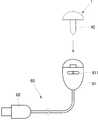
도 11은 도 1의 휴대용 자외선 살균 장치를 USB 커넥터에 연결한 상태를 나타낸 도면이다. 도 11을 참조하면, 본 발명은 USB 커넥터(60)를 추가로 구성할 수 있다. USB 커넥터(60)의 일측 단부는 암형 커넥터부(61)가 설치되어 있어서 상기 휴대용 자외선 살균 장치를 끼울 수 있다. USB 커넥터(60)의 타측 단부는 상기 일측 단부와 플렉시블한 케이블로 연결되며(경우에 따라 케이블 없이 사용될 수도 있다), PC 등의 암형 USB 단자에 연결될 수 있는 수형 USB 단자(62)가 형성되어 있다. 따라서 휴대용 자외선 살균 장치(1)를 USB 커넥터(60)의 암형 커넥터부(61)에 끼우고, 수형 USB 단자(62)를 PC 등의 암형 USB 단자에 끼우면 상기 휴대용 자외선 살균 장치(1)에는 전원이 공급됨은 물론 각종 신호가 입출될 수 있다. 따라서 PC에 설치되는 프로그램을 통해 휴대용 자외선 살균 장치(1)를 제어하거나, 암형 커넥터부(61)에 설치된 스위치(611)를 제어하여 휴대용 자외선 살균 장치(1)를 온오프 하는 것이 가능하다.Fig. 11 is a view showing a state in which the portable ultraviolet sterilizing apparatus of Fig. 1 is connected to a USB connector. Fig. Referring to FIG. 11, the present invention may further comprise a
물론 직접 도시하지는 아니하였으나, PC나 랩톱 등의 이어폰 단자에 상기 휴대용 자외선 살균 장치(1)를 직접 설치하여 사용하는 것 역시 가능하다.Although not shown directly, it is also possible to use the portable
본 발명의 휴대용 자외선 소독 장치는 전원을 제공할 수 있는 배터리팩(70)에 설치되는 것도 가능하다.The portable ultraviolet disinfecting apparatus of the present invention may be installed in a
도 12는 도 1의 휴대용 자외선 살균 장치를 배터리팩에 연결하는 상태를 나타낸 도면이다.12 is a view showing a state in which the portable ultraviolet sterilizing apparatus of FIG. 1 is connected to a battery pack.
배터리팩(70)에는 휴대용 자외선 살균 장치를 수용하는 수용홈(71)을 구비하고, 상기 수용홈 내에는 상기 휴대용 자외선 살균 장치(1)의 커넥터(40)가 끼워지는 암형커넥터(72)가 구비되어 있다. 따라서 휴대용 자외선 살균 장치(1)의 커넥터(40)를 암형커넥터(72)에 연결하며 상기 휴대용 자외선 살균 장치(1)를 배터리팩(70)의 수용홈(71)에 끼우는 것이 가능하다.The
상기 배터리팩(70) 내에는 근거리통신모듈(미도시)이 내장되어 있다. 가령 근거리통신모듈은 블루투스, 와이파이, 지그비 등 공지의 근거리통신모듈이 사용될 수 있다. 따라서 배터리팩(70)에 내장된 배터리(75)를 UV LED(12)에 공급되는 전원으로 사용하고, 배터리팩의 내부에 설치된 근거리통신모듈을 통해 상기 UV LED에 공급되는 전원을 제어할 수 있다. 상기 배터리팩 내부에 설치된 근거리통신모듈과 연결되는 장치는 스마트폰과 같은 휴대용 단말(50)이거나, PC일 수 있다.A local communication module (not shown) is built in the
또한 배터리팩(70) 내에는 상기 UV LED에 공급되는 전원을 제어하는 칩(미도시)이 실장되거나, 하드웨어 스위치(미도시)가 설치될 수도 있다.A chip (not shown) for controlling the power supplied to the UV LED may be mounted in the
도 12에는 휴대용 자외선 소독 장치(1)가 직접 배터리팩(70)에 설치된 상태를 도시하고 있으나, 휴대용 자외선 소독 장치(1)가 상술한 USB 커넥터(60)를 통해 상기 배터리팩(70)에 연결되는 것 역시 가능하다.12 shows a state in which the portable
앞서 실시예들은 휴대용 자외선 소독 장치가 커넥터(40)를 구비하는 것을 기준으로 설명하였으나, 본 발명은 반드시 이러한 구조에 한정되는 것은 아니다. 이하에서는 자체적으로 전원을 구비하는 휴대용 자외선 소독 장치의 실시예들에 대해 설명한다.Although the above embodiments have been described on the basis that the portable ultraviolet disinfecting device is provided with the
도 13은 본 발명에 따른 휴대용 자외선 살균 장치의 다른 일 실시예를 나타낸 도면이다. 도 13에 도시된 휴대용 자외선 살균 장치는 도 1과 도 2의 휴대용 자외선 살균 장치와 대비하여, 커넥터(40) 대신 하우징(30) 내에 배터리(75)를 구비하는 점에 차이가 있다. 하우징(30)은 사람이 파지하기 편리한 정도의 규격으로 형성되고, 배터리(75)는 그 내부에 내장되어 있다. 물론 배터리(75)에서 UV LED(12)에 제공되는 전원은 하우징(30) 내에 설치된 제어 칩(미도시)에 의해 제어될 수 있다.13 is a view showing another embodiment of the portable ultraviolet sterilizing apparatus according to the present invention. The portable ultraviolet sterilizing apparatus shown in Fig. 13 differs from the portable ultraviolet sterilizing apparatus of Figs. 1 and 2 in that a
도 13의 휴대용 자외선 살균 장치는, 하우징(30)에 전원버튼이 설치되어 있어서 수동으로 UV LED를 온오프 하는 것이 가능하다. 또한 블루투스, NFC와 같은 근거리 통신 모듈이 설치되어 있어, 근거리 통신으로 휴대용 단말과 연결하여 전원과 작동 시간 등을 제어하는 것이 가능하다. 휴대용 단말의 제어 애플리케이션은 앞서 설명한 애플리케이션과 크게 다르지 않으므로, 중복 설명은 하지 않는다.In the portable ultraviolet sterilizing apparatus of Fig. 13, the power button is provided on the
도 14는 본 발명에 따른 휴대용 자외선 살균 장치의 또 다른 일 실시예를 나타낸 도면이다. 도 14에 도시된 휴대용 자외선 살균 장치는 하우징(30-1, 30-2, 30-3)이 동적으로 그 형태가 변형되는 구조라는 점과, 이러한 구조에 의해 가지는 통상적인 차이 외에는 도 13의 휴대용 자외선 살균 장치와 유사하다. 즉 도 14의 휴대용 자외선 살균 장치 역시 UV LED(12), UV LED가 실장되는 기판(10), 가시광 LED, 옵틱(20), 배터리(75), 근거리 통신모듈 등을 구비할 수 있다는 점에서 도 13의 휴대용 자외선 살균 장치와 동일하다.14 is a view showing still another embodiment of the portable ultraviolet sterilizing apparatus according to the present invention. The portable ultraviolet sterilizing apparatus shown in Fig. 14 is different from the conventional portable ultraviolet sterilizing apparatus in that the housing 30-1, 30-2, and 30-3 is dynamically deformed in shape, It is similar to ultraviolet sterilization equipment. That is, the portable ultraviolet sterilizer of FIG. 14 may also include the
도 14의 휴대용 자외선 살균 장치는 하우징(30-1) 내에 동축의 다른 하우징(30-2, 30-3)이 중첩된 형태이다. 하우징들의 직경은 서로 다르다. 도 14의 (a)에 도시된 바와 같이 여러 하우징을 서로 중첩시킨 상태에서는 UV LED가 외부로 노출되지 않고, 이 때에는 UV LED에 전원이 공급되지 않는다.The portable ultraviolet sterilizing apparatus of Fig. 14 is a structure in which other coaxial housings 30-2 and 30-3 are stacked in the housing 30-1. The diameters of the housings are different. As shown in FIG. 14 (a), the UV LEDs are not exposed to the outside in a state where the housings are overlapped with each other, and no power is supplied to the UV LEDs at this time.
반면 도 14의 (b)에 도시된 바와 같이 하우징(30-2, 30-3)들을 인출하여 하우징의 형태를 확장시킨 상태에서는 UV LED(12)가 외부로 노출되며, 이에 따라 UV LED(12)에 전원이 공급될 수 있다. UV LED(12)에 대한 전원의 공급은, 하우징을 인출하였을 때 자동으로 이루어지도록 할 수도 있고, 하우징을 인출한 것을 전제로 전원 스위치(미도시)를 켬으로써 이루어지도록 할 수도 있다.On the other hand, as shown in FIG. 14 (b), when the housings 30-2 and 30-3 are drawn out to extend the shape of the housing, the
도 15는 본 발명에 따른 휴대용 자외선 살균 장치의 또 다른 일 실시예를 나타낸 도면이다. 도 15에 도시된 휴대용 자외선 살균 장치(5)는 도 14에 도시된 휴대용 자외선 살균 장치(4)와 대비하였을 때 하우징이 동적으로 그 형태가 변형되는 구조라는 점이 유사하나, 하우징이 변하는 형태에 차이가 있다. 즉 도 15의 휴대용 자외선 살균 장치는 UV LED(12), UV LED가 실장되는 기판(10), 가시광 LED, 옵틱(20), 배터리(75), 근거리 통신모듈 등을 구비할 수 있다는 점에서 도 13의 휴대용 자외선 살균 장치와 동일하고, 동적으로 그 형태가 바뀐다는 점에서 도 14와 유사하지만, 그 바뀌는 동작에는 차이가 있다.15 is a view showing still another embodiment of the portable ultraviolet sterilizing apparatus according to the present invention. The portable ultraviolet sterilizing apparatus 5 shown in FIG. 15 is similar to the portable
도 15의 휴대용 자외선 살균 장치는 두 하우징(30-4, 30-5)가 힌지(301)를 기준으로 서로 접혀져 있는 형태와 펼쳐진 형태 사이에서 그 형태가 변경된다. 이는 두 하우징을 접었을 때 서로 마주하는 면에 UV LED가 배치된 구조이므로, 도 15의 (a)에 도시된 바와 같이 두 하우징을 접은 상태에서는 UV LED가 외부로 노출되지 않고, 이 때에는 UV LED에 전원이 공급되지 않는다.In the portable ultraviolet sterilizing apparatus of Fig. 15, the shapes of the two housings 30-4 and 30-5 are changed between the folded form and the folded form with respect to the
반면 도 15의 (b)에 도시된 바와 같이 하우징(30-4, 30-5)을 힌지(301)를 기준으로 펼친 상태에서는 UV LED(12)가 외부로 노출되며, 이에 따라 UV LED(12)에 전원이 공급될 수 있다. UV LED(12)에 대한 전원의 공급은, 하우징을 펼쳤을 때 자동으로 이루어지도록 할 수도 있고, 하우징을 펼친 상태를 전제로 전원 스위치(미도시)를 켬으로써 이루어지도록 할 수도 있다.On the other hand, as shown in FIG. 15 (b), when the housings 30-4 and 30-5 are extended with respect to the
본 발명의 UV LED(12)에서 조사되는 자외선의 피크파장은 UVC 영역에 존재하는 것이 바람직하다. UV LED는 피크파장에 광이 집중되어 반치폭(spectrum half width)이 좁은 광 특성을 가진다. 또한 성분을 조정하여 피크파장을 조절하는 것 역시 가능하다. 이러한 UV LED의 특성을 활용하여 5nm 단위로 250nm ~ 280nm 영역에서 살균효율을 측정한 결과, 박테리아 계열의 세균은 UV LED에서 조사되는 자외선의 피크파장이 265~270nm 영역에 있을 때 살균 효율이 가장 높았으며, 바이러스 계열은 260nm 전후에서 살균 효율이 가장 높았다.The peak wavelength of the ultraviolet light irradiated from the
이상과 같이 본 발명에 대해서 예시한 도면을 참조로 하여 설명하였으나, 본 명세서에 개시된 실시예와 도면에 의해 본 발명이 한정되는 것은 아니며, 본 발명의 기술사상의 범위 내에서 통상의 기술자에 의해 다양한 변형이 이루어질 수 있음은 자명하다. 아울러 앞서 본 발명의 실시예를 설명하면서 본 발명의 구성에 따른 작용 효과를 명시적으로 기재하여 설명하지 않았을 지라도, 해당 구성에 의해 예측 가능한 효과 또한 인정되어야 함은 당연하다.While the present invention has been particularly shown and described with reference to exemplary embodiments thereof, it is to be understood that the scope of the invention is not limited to the disclosed exemplary embodiments. It is obvious that a transformation can be made. Although the embodiments of the present invention have been described in detail above, the effects of the present invention are not explicitly described and described, but it is needless to say that the effects that can be predicted by the configurations should also be recognized.
1, 2, 3, 4, 5: 휴대용 자외선 소독 장치
10: 기판
12: UV LED
14: 가시광 LED
20: 옵틱
21: 광각 옵틱
22: 협각 옵틱
23: 자외선 보정 옵틱
24: 가시광선 보정 옵틱
30,30-1,30-2,30-3,30-4,30-5: 하우징
301: 힌지
40: 커넥터
50: 휴대용 단말
52: 카메라모듈
60: USB 커넥터
61: 암형 커넥터부
611: 스위치
62: USB 단자
70: 배터리팩
71: 수용홈
72: 암형커넥터
75: 배터리1, 2, 3, 4, 5: portable ultraviolet disinfection device
10: substrate
12: UV LED
14: Visible light LED
20: Optics
21: wide-angle optics
22:
23: UV correction optics
24: visible light compensation optics
30, 30-1, 30-2, 30-3, 30-4, 30-5:
301: Hinge
40: Connector
50: Portable terminal
52: Camera module
60: USB connector
61: female connector portion
611: Switch
62: USB terminal
70: Battery pack
71: receiving groove
72: Female connector
75: Battery
Claims (24)
Translated fromKorean상기 기판(10)을 수용하는 하우징(30);
상기 UV LED(12)에서 조사되는 자외선의 확산각을 조절하는 옵틱(20); 및
상기 기판(10)과 전기적으로 연결되며, 외부로부터 전원을 공급받는 경로가 되는 커넥터(40);를 포함하는 휴대용 자외선 소독 장치.
A substrate 10 on which the UV LED 12 is mounted;
A housing (30) for receiving the substrate (10);
An optic 20 for adjusting a diffusion angle of ultraviolet light emitted from the UV LED 12; And
And a connector (40) electrically connected to the substrate (10) and serving as a path through which power is supplied from the outside.
상기 커넥터(40)는, 상기 기판(10)을 기준으로 상기 UV LED(12)의 자외선 조사 방향의 반대방향 또는 UV LED(12)의 자외선 조사 방향의 중심방향과 수직한 방향으로 연장 형성된 수형 3.5파이 이어폰 커넥터인 휴대용 자외선 소독 장치.
The method according to claim 1,
The connector 40 includes a male mold 3.5 extending in the direction opposite to the ultraviolet ray irradiation direction of the UV LED 12 or in a direction perpendicular to the center direction of the UV light irradiation direction of the UV LED 12 with respect to the substrate 10 A portable ultraviolet disinfection device that is a pie earphone connector.
상기 커넥터(40)는, 적어도 상기 기판(10)을 기준으로 상기 UV LED(12)의 자외선 조사 방향의 반대방향과 UV LED(12)의 자외선 조사 방향의 중심방향과 수직한 방향 사이에서 회전 가능한 휴대용 자외선 소독 장치.
The method of claim 2,
The connector 40 is rotatable between a direction opposite to the ultraviolet ray irradiation direction of the UV LED 12 and a direction perpendicular to the center direction of the ultraviolet ray irradiation direction of the UV LED 12, Portable ultraviolet disinfection device.
상기 기판(10) 상의 UV LED(12) 부근에는 가시광 LED(14)가 실장된 휴대용 자외선 소독 장치.
The method according to claim 1,
Wherein the visible light LED (14) is mounted near the UV LED (12) on the substrate (10).
상기 옵틱(20)은 상기 UV LED(12)에서 조사되는 자외선과, 상기 가시광 LED(14)에서 조사되는 가시광선의 확산각을 모두 제어하는 휴대용 자외선 소독 장치.
The method of claim 4,
Wherein the optics (20) controls the diffusion angle of ultraviolet light emitted from the UV LED (12) and visible light emitted from the visible light LED (14).
상기 옵틱(20)은 확산각을 더 넓게 하는 광각 옵틱(21)과 확산각을 더 좁게 하는 협각 옵틱(22) 중 적어도 어느 하나를 포함하는 휴대용 자외선 소독 장치.
The method according to claim 1,
Wherein the optic (20) comprises at least one of a wide-angle optic (21) that widens the diffusion angle and a narrow angle optic (22) that narrows the diffusion angle.
상기 옵틱(20)은 착탈 가능하게 설치되는 휴대용 자외선 소독 장치.
The method according to claim 1,
Wherein the optic (20) is detachably installed.
상기 UV LED(12)와 가시광 LED(14) 중 적어도 어느 하나의 LED 전방에는 보정 옵틱(23,24)이 설치되는 휴대용 자외선 소독 장치.
The method of claim 4,
Wherein at least one of the UV LED (12) and the visible light LED (14) is provided with correction optics (23, 24) in front of the LED.
상기 UV LED(12)와 가시광 LED(14) 중 어느 한 종류의 LED를 중심으로 하여 그 둘레에 다른 한 종류의 LED가 복수 개 방사상으로 실장되는 휴대용 자외선 소독 장치.
The method of claim 4,
Wherein a plurality of LEDs of different types are radially mounted on the circumference of any one of the UV LED (12) and the visible light LED (14).
A portable terminal equipped with the portable ultraviolet disinfecting device according to any one of claims 1 to 9.
상기 휴대용 단말에는 상기 휴대용 자외선 소독 장치에 공급하는 전원의 공급 여부와, 전원의 공급 시간을 제어하는 애플리케이션이 설치되는 휴대용 단말.
The method of claim 10,
Wherein the portable terminal is provided with an application for controlling whether or not to supply power to the portable ultraviolet disinfecting device and for controlling the supply time of the power.
상기 애플리케이션은 휴대용 단말의 위치 정보와, 서버로부터 전송되는 감염 위험 지역에 대한 정보를 비교하여 상기 휴대용 자외선 소독 장치에 공급되는 전원을 제어하는 휴대용 단말.
The method of claim 11,
Wherein the application controls power supplied to the portable ultraviolet disinfecting device by comparing positional information of the portable terminal with information about an infectious danger area transmitted from the server.
상기 애플리케이션은 휴대용 단말의 자세 정보가 소정의 자세에 해당하는 경우 상기 휴대용 자외선 소독 장치에 공급되는 전원을 제어하는 휴대용 단말.
The method of claim 11,
Wherein the application controls power supplied to the portable ultraviolet disinfecting device when attitude information of the portable terminal corresponds to a predetermined attitude.
상기 애플리케이션은 휴대용 단말에 설치된 카메라모듈에서 촬영되는 화각을 소프트웨어적으로 제어하여 상기 휴대용 자외선 소독 장치의 자외선 확산각과 일치시키는 휴대용 단말.
The method of claim 11,
Wherein the application matches the ultraviolet ray diffusion angle of the portable ultraviolet disinfecting device by controlling the angle of view photographed by the camera module installed in the portable terminal.
상기 애플리케이션은 휴대용 단말에 설치된 카메라모듈에서 촬영되는 영상에서 특정 형상을 인지한 경우 상기 휴대용 자외선 소독 장치에 공급되는 전원을 제어하는 휴대용 단말.
The method of claim 11,
Wherein the application controls power supplied to the portable ultraviolet disinfecting device when recognizing a specific shape in an image photographed by a camera module installed in the portable terminal.
상기 USB 커넥터(60)의 일측 단부에는 상기 휴대용 자외선 소독 장치가 끼워지는 암형 커넥터부(61)가 구비되고, 상기 USB 커넥터의 타측 단부에는 전원을 공급할 수 있는 암형 USB 단자에 끼워지는 수형 USB 단자(62)가 구비되는 USB 커넥터.
A USB connector provided with the portable ultraviolet disinfecting device according to any one of claims 1 to 9,
At one end of the USB connector 60, there is provided a female connector 61 to which the portable ultraviolet disinfecting device is inserted. The other end of the USB connector is provided with a male USB terminal 62).
상기 USB 커넥터에는 상기 UV LED에 공급되는 전원의 온오프를 제어하는 스위치(611)가 설치된 USB 커넥터.
18. The method of claim 16,
The USB connector is provided with a switch (611) for controlling on / off of power supplied to the UV LED.
상기 휴대용 자외선 살균 장치의 커넥터(40)와 연결되는 암형 커넥터(41)를 구비하는 배터리팩.
A battery pack provided with the portable ultraviolet disinfecting device according to any one of claims 1 to 9,
And a female connector (41) connected to the connector (40) of the portable ultraviolet sterilizer.
근거리통신모듈을 더 구비하는 것을 특징으로 하는 배터리팩.
19. The method of claim 18,
And a short-range communication module.
상기 기판(10)을 수용하는 하우징(30);
상기 UV LED(12)에서 조사되는 자외선의 확산각을 조절하는 옵틱(20); 및
상기 기판(10)과 전기적으로 연결되며, 상기 하우징(30) 내에 수용되어 상기 UV LED(12)에 전원을 공급하는 배터리(75);를 포함하는 휴대용 자외선 소독 장치.
A substrate 10 on which the UV LED 12 is mounted;
A housing (30) for receiving the substrate (10);
An optic 20 for adjusting a diffusion angle of ultraviolet light emitted from the UV LED 12; And
And a battery (75) electrically connected to the substrate (10) and accommodated in the housing (30) to supply power to the UV LED (12).
근거리통신모듈을 더 구비하는 것을 특징으로 하는 휴대용 자외선 소독 장치.
The method of claim 20,
Further comprising a short range communication module.
상기 하우징은 단면적이 다른 동축의 하우징이 서로 중첩되어 전체적인 길이가 축소되고, 적어도 하나의 하우징이 다른 하우징에 대해 인출되었을 때 전체적인 길이가 늘어나는 구조이며,
적어도 하나의 하우징이 다른 하우징에 대해 인출되었을 때 UV LED(12)가 외부로 노출되는 휴대용 자외선 소독 장치.
The method of claim 20,
The housing has a structure in which coaxial housings having different cross sectional areas are overlapped with each other to reduce the overall length, and the overall length of the housing is increased when the at least one housing is drawn out to the other housing,
Wherein the UV LED (12) is exposed to the outside when at least one housing is drawn out to the other housing.
상기 하우징은 힌지점을 기준으로 펼쳐지거나 접혀지는 적어도 2개의 분할된 하우징을 구비하며,
상기 힌지점을 기준으로 분할된 하우징이 펼쳐졌을 때 UV LED(12)가 외부로 노출되는 휴대용 자외선 소독 장치.
The method of claim 20,
The housing has at least two divided housings that are unfolded or folded relative to a hinge point,
Wherein the UV LED (12) is exposed to the outside when the housing divided on the basis of the hinge point is unfolded.
상기 UV LED(12)에서 조사되는 자외선의 피크파장은 240nm~280nm내에 존재하는 휴대용 자외선 소독 장치.
The method according to any one of claims 1 to 9 and 20 to 23,
Wherein a peak wavelength of ultraviolet light irradiated from the UV LED (12) is within a range of 240 nm to 280 nm.
Priority Applications (1)
| Application Number | Priority Date | Filing Date | Title |
|---|---|---|---|
| KR1020150084560AKR20160148140A (en) | 2015-06-15 | 2015-06-15 | A Portable Ultra-Violet Light Sterilizer |
Applications Claiming Priority (1)
| Application Number | Priority Date | Filing Date | Title |
|---|---|---|---|
| KR1020150084560AKR20160148140A (en) | 2015-06-15 | 2015-06-15 | A Portable Ultra-Violet Light Sterilizer |
Publications (1)
| Publication Number | Publication Date |
|---|---|
| KR20160148140Atrue KR20160148140A (en) | 2016-12-26 |
Family
ID=57733949
Family Applications (1)
| Application Number | Title | Priority Date | Filing Date |
|---|---|---|---|
| KR1020150084560AWithdrawnKR20160148140A (en) | 2015-06-15 | 2015-06-15 | A Portable Ultra-Violet Light Sterilizer |
Country Status (1)
| Country | Link |
|---|---|
| KR (1) | KR20160148140A (en) |
Cited By (8)
| Publication number | Priority date | Publication date | Assignee | Title |
|---|---|---|---|---|
| KR20200031866A (en) | 2018-09-17 | 2020-03-25 | 한국광기술원 | Portable sterilization system and method for controlling the same |
| KR102324812B1 (en)* | 2021-02-18 | 2021-11-11 | 주식회사 테이크케어 | Portable UV sterilizer |
| KR20210157140A (en) | 2020-06-19 | 2021-12-28 | 진무성 | Lighting device for serilizing by using uv led |
| KR20220002253U (en) | 2021-03-12 | 2022-09-20 | 나경주 | Portable UV LED Sterilizer |
| KR20220128731A (en)* | 2021-03-15 | 2022-09-22 | (주)쿠첸 | Portable sterilizer |
| EP4079334A3 (en)* | 2021-04-20 | 2022-11-23 | The Boeing Company | Adaptable sanitizing systems and methods |
| US11617805B2 (en) | 2018-10-29 | 2023-04-04 | Savant Technologies Llc | Light and disinfection system with coincident illumination range |
| WO2023070484A1 (en)* | 2021-10-29 | 2023-05-04 | 张柏伟 | Disinfection device and handheld disinfection device |
- 2015
- 2015-06-15KRKR1020150084560Apatent/KR20160148140A/ennot_activeWithdrawn
Cited By (8)
| Publication number | Priority date | Publication date | Assignee | Title |
|---|---|---|---|---|
| KR20200031866A (en) | 2018-09-17 | 2020-03-25 | 한국광기술원 | Portable sterilization system and method for controlling the same |
| US11617805B2 (en) | 2018-10-29 | 2023-04-04 | Savant Technologies Llc | Light and disinfection system with coincident illumination range |
| KR20210157140A (en) | 2020-06-19 | 2021-12-28 | 진무성 | Lighting device for serilizing by using uv led |
| KR102324812B1 (en)* | 2021-02-18 | 2021-11-11 | 주식회사 테이크케어 | Portable UV sterilizer |
| KR20220002253U (en) | 2021-03-12 | 2022-09-20 | 나경주 | Portable UV LED Sterilizer |
| KR20220128731A (en)* | 2021-03-15 | 2022-09-22 | (주)쿠첸 | Portable sterilizer |
| EP4079334A3 (en)* | 2021-04-20 | 2022-11-23 | The Boeing Company | Adaptable sanitizing systems and methods |
| WO2023070484A1 (en)* | 2021-10-29 | 2023-05-04 | 张柏伟 | Disinfection device and handheld disinfection device |
Similar Documents
| Publication | Publication Date | Title |
|---|---|---|
| KR20160148140A (en) | A Portable Ultra-Violet Light Sterilizer | |
| US9925390B2 (en) | Mobile device case with ultraviolet light sanitizer and light therapy | |
| WO2017048877A1 (en) | Mobile device case with ultraviolet light sanitizer and light therapy | |
| CN110997016B (en) | System and method for sterilization using ultraviolet radiation | |
| EP3164161B1 (en) | Device for the sterilisation of stethoscopes | |
| US9114184B2 (en) | Device for the hygienisation of medical instruments | |
| JP7407000B2 (en) | Hanging strap and gripping member | |
| CN113424329A (en) | Optical module and device incorporating the same | |
| US20210379219A1 (en) | Portable sanitizing arrangement | |
| US20220273833A1 (en) | Far uv-c apparatus and confirmation of use | |
| US20210353786A1 (en) | Handheld uv-c sanitizing apparatus and method | |
| KR20180111356A (en) | A photo-therapy device for rhinitis cure | |
| US20220193282A1 (en) | System for mobile smart devices that sterilize targets and increase the transparency of the process | |
| CN206007212U (en) | A kind of Anoscope and proctoscope | |
| CN108309224A (en) | Vaginal dilator and medication | |
| KR20210137615A (en) | Sterilization device using UV-C light | |
| US20170348444A1 (en) | Sterilizer for portable electronic device | |
| CN212415008U (en) | Electronic equipment and electronic equipment protective sleeve integrated with sterilization function | |
| US11517634B2 (en) | Field of reach ultraviolet light disinfecting system | |
| KR102379175B1 (en) | Automatic Ordering System for Infection Prevention,And Method for Working the Same | |
| JP3230230U (en) | UV sterilizer | |
| KR102572622B1 (en) | Ultraviolet ray sterilizing apparatus | |
| KR102381480B1 (en) | Unmanned Ordering System for Infection Prevention, And Method for Working the Same | |
| ES1253694U (en) | FACIAL AND WORK PROTECTION DEVICE (Machine-translation by Google Translate, not legally binding) | |
| US20230211025A1 (en) | Far uv-c apparatus and confirmation of use |
Legal Events
| Date | Code | Title | Description |
|---|---|---|---|
| PA0109 | Patent application | Patent event code:PA01091R01D Comment text:Patent Application Patent event date:20150615 | |
| PG1501 | Laying open of application | ||
| PC1203 | Withdrawal of no request for examination |