KR20160147908A - Amusement attraction fluid control system - Google Patents
Amusement attraction fluid control systemDownload PDFInfo
- Publication number
- KR20160147908A KR20160147908AKR1020167032794AKR20167032794AKR20160147908AKR 20160147908 AKR20160147908 AKR 20160147908AKR 1020167032794 AKR1020167032794 AKR 1020167032794AKR 20167032794 AKR20167032794 AKR 20167032794AKR 20160147908 AKR20160147908 AKR 20160147908A
- Authority
- KR
- South Korea
- Prior art keywords
- vehicle
- fluid
- water
- pump
- channel
- Prior art date
- Legal status (The legal status is an assumption and is not a legal conclusion. Google has not performed a legal analysis and makes no representation as to the accuracy of the status listed.)
- Abandoned
Links
Images


Classifications
- A—HUMAN NECESSITIES
- A63—SPORTS; GAMES; AMUSEMENTS
- A63G—MERRY-GO-ROUNDS; SWINGS; ROCKING-HORSES; CHUTES; SWITCHBACKS; SIMILAR DEVICES FOR PUBLIC AMUSEMENT
- A63G21/00—Chutes; Helter-skelters
- A63G21/12—Chutes; Helter-skelters with special cars, e.g. horse-shaped
- A—HUMAN NECESSITIES
- A63—SPORTS; GAMES; AMUSEMENTS
- A63G—MERRY-GO-ROUNDS; SWINGS; ROCKING-HORSES; CHUTES; SWITCHBACKS; SIMILAR DEVICES FOR PUBLIC AMUSEMENT
- A63G21/00—Chutes; Helter-skelters
- A63G21/18—Water-chutes
Landscapes
- Vehicle Cleaning, Maintenance, Repair, Refitting, And Outriggers (AREA)
- Special Spraying Apparatus (AREA)
- Structures Of Non-Positive Displacement Pumps (AREA)
- Reciprocating Pumps (AREA)
Abstract
Translated fromKoreanDescription
Translated fromKorean본 발명은 일반적으로 놀이공원에 관련이 있으며, 특히 유체를 기반으로 하는 놀이공원에 관련이 있다.The present invention relates generally to amusement parks, and more particularly to amusement parks based on fluid.
지난 몇 십 년 동안, 물을 기반으로 하는 놀이기구들이 인기가 높아지고 있다. 그러한 놀이기구들은, 흥분시키는 스플래시 효과 및 물의 냉각 효과의 특징과 함께, 롤러 코스트 기구들과 유사한 스릴을 제공할 수 있다.Over the last few decades, water-based rides have become more popular. Such rides can provide a thrill similar to roller-cost mechanisms, with features of exciting splash effect and cooling effect of water.
가장 일반적인 물을 기반으로 하는 놀이기구들은, 참가자들이 그들의 신체를 슬라이딩 하거나 차량을 타고 슬라이딩하는, 채널 또는 "수로(flume)"를 따라 슬라이딩하는 수로 스타일의 워터슬라이들이다. 차량/신체와 수로 표면 사이에 윤활(lubrication)을 제공하고 전술한 냉각 및 스플래시 효과를 제공하기 위해 수로에 물이 공급된다. 일반적으로, 수로 내 참가자의 움직임은 주로 중력과 결합된 수로의 윤곽(언덕, 골, 회전, 하락, 등)에 의해 제어된다.The most common water-based rides are water-style water slides that slide along a channel or "flume " where participants slide their bodies or ride in vehicles. Water is supplied to the waterway to provide lubrication between the vehicle / body and the waterway surface and to provide the cooling and splashing effects described above. In general, the movement of a participant in the channel is controlled primarily by the contours (hills, valleys, rotations, drops, etc.) of the channels associated with gravity.
참가자에 의해 기대되는 스릴이 증가하여 온 것에 따라, 수로에서 참가자들의 움직임에 대한 더 좋은 제어에 대한 요구는 그에 상응하여 증가하여 왔다. 따라서, 중력 이외의, 참가자들의 움직임을 가속시키거나 감속시키는 다양한 기술들이 적용되어 왔다. 예를 들어, 강한 워터젯에 의해 참가자들의 움직임을 가속되거나 감속될 수 있다. 다른 놀이기구들은 참가자를 상부로 이동시키기 위해 콘베이어 벨트를 사용하며, 참가자들 단독의 운동량으로는 상부에 이를 수 없을 것이다.As the thrills expected by the participants have increased, the demand for better control over the player's movements in the waterways has been correspondingly increased. Thus, various techniques have been applied to accelerate or decelerate the movement of participants other than gravity. For example, strong water jets can accelerate or slow down participants' movements. Other rides will use a conveyor belt to move the participants up, and the participants will not be able to reach the top with their own momentum.
온도로 인해 야외활동을 즐길 수 없을 때, 참가자들이 야외활동을 즐길수 있게 하는, 물의 냉각 효과가 있는 수상 놀이기구들은 더운 기후에서 매우 인기가 높다. 그러한 장소들에는 종종 수자원이 제한되어 가뭄이 들 수 있고 비용이 많이 드는 에너지 때문에, 그러한 장소들은 도전을 제기한다. 이러한 상황은 수상 놀이기구를 통하여 물을 이동시키기 위한 큰 에너지원을 작동하고 활용하기 위해 큰 부피의 물을 필요로 하는 수상 놀이기구의 건설을 억제한다.Water-cooled aquariums that allow participants to enjoy outdoor activities when temperatures are not enjoying outdoor activities are very popular in hot climates. Such places often present challenges because of the limited water resources and drought and costly energy. This situation restrains the construction of a water riding apparatus that requires a large volume of water to operate and utilize a large energy source for moving water through the water rides.
본 발명의 측면은 유체 공급원; 적어도 하나의 펌프; 적어도 하나의 유체 피쳐(fluid feature); 유체 공급원과 적어도 하나의 펌프를 적어도 하나의 유체 피쳐에 연결하는 복수의 도관들; 및 제어기를 포함하는 놀이공원 유체 제어 시스템에 관련이 있으며, 적어도 하나의 펌프는 도관들을 통하여 적어도 하나의 유체 피쳐에 유체를 퍼올리도록 구성되며, 각각의 유체 피쳐에 유체를 운반하기 위해, 제어기는 적어도 하나의 펌프를 제어하도록 조정된다.Aspects of the present invention include a fluid source; At least one pump; At least one fluid feature; A plurality of conduits connecting a fluid source and at least one pump to at least one fluid feature; And a controller, wherein the at least one pump is configured to pump fluid to the at least one fluid feature through the conduits, and in order to deliver fluid to each fluid feature, the controller And is adjusted to control at least one pump.
일부 실시예에서, 놀이공원 유체 제어 시스템은 적어도 하나의 가변 주파수 구동 중간 제어기(variable frequency drive intermediate the controller) 및 제어기로부터 수신된 입력에 기초하여 적어도 하나의 펌프 각각을 제어하기 위한 적어도 하나의 펌프를 포함한다.In some embodiments, the amusement park fluid control system includes at least one variable frequency drive intermediate controller and at least one pump for controlling each of the at least one pump based on the input received from the controller .
일부 실시예에서, 놀이공원 유체 제어 시스템은 적어도 하나의 센서를 더 포함하며, 적어도 하나의 센서는 제어기에 입력을 제공한다.In some embodiments, the amusement park fluid control system further includes at least one sensor, wherein at least one sensor provides input to the controller.
일부 실시예에서, 적어도 하나의 센서는 참가자의 적어도 하나의 피쳐(feature)를 검출하도록 조정된 적어도 하나의 제1 센서를 포함한다.In some embodiments, the at least one sensor includes at least one first sensor adapted to detect at least one feature of a participant.
일부 실시예에서, 피쳐는 위치와 속도 중 적어도 하나이다.In some embodiments, the feature is at least one of position and velocity.
일부 실시예에서, 적어도 하나의 센서는 적어도 하나의 유체 흐름 특성을 검출하도록 조정된 적어도 하나의 제2 센서를 포함한다.In some embodiments, the at least one sensor includes at least one second sensor adapted to detect at least one fluid flow characteristic.
일부 실시예에서, 적어도 하나의 유체 흐름 특성은 적어도 하나의 유체 압력 및 유체 흐름률 중 하나이다.In some embodiments, the at least one fluid flow characteristic is one of at least one fluid pressure and a fluid flow rate.
일부 실시예에서, 적어도 하나의 유체 피쳐는 복수의 유체 피쳐들 및 복수의 펌프들을 포함하는 적어도 하나의 펌프를 포함하며, 복수의 유체 피쳐들 각각은 복수의 펌프들의 적어도 하나의 관련된 펌프를 가진다.In some embodiments, the at least one fluid feature comprises at least one pump comprising a plurality of fluid features and a plurality of pumps, each of the plurality of fluid features having at least one associated pump of the plurality of pumps.
일부 실시예에서, 참가자가 유체 피쳐 근처에 있을 때, 적어도 하나의 펌프 각각은 관련된 유체 피쳐로부터 유체 흐름률을 증가시키고, 참가자가 유체 피쳐로부터 멀리 있을 때, 적어도 하나의 펌프 각각은 관련된 유체 피쳐로부터 유체 흐름률을 감소시키기 위해 조정된다.In some embodiments, when the participant is near the fluid feature, each of the at least one pump increases the fluid flow rate from the associated fluid feature, and when the participant is away from the fluid feature, each of the at least one pump Is adjusted to reduce the fluid flow rate.
일부 실시예에서, 놀이공원 유체 제어 시스템은 적어도 하나의 펌프로부터 유체 흐름률을 제어하기 위한 적어도 하나의 펌프 각각과 관련된 가변 주파수 구동기(variable frequency drive)를 더 포함한다.In some embodiments, the amusement park fluid control system further comprises a variable frequency drive associated with each of the at least one pump for controlling the fluid flow rate from the at least one pump.
본 발명의 또다른 측면은 놀이공원 수상 제어 시스템 및 슬라이딩 표면을 포함하는 워터슬라이드 부분과 관련이 있고, 각각의 유체 피쳐(fluid feature)는 워터 피쳐(water feature)이며, 참가자들이 각각의 워터 피쳐을 향하여 슬라이딩함에 따라, 적어도 하나의 펌프 각각은 각각의 워터 피쳐에 대하여 물의 흐름을 증가시키고, 참가자들이 각각의 워터 피쳐으로부터 슬라이딩하여 멀어짐에 따라, 적어도 하나의 펌프 각각은 각각의 워터 피쳐에 대하여 물의 흐름을 감소시키도록 조정된다.Another aspect of the invention relates to an amusement park water control system and a water slide portion comprising a sliding surface, wherein each fluid feature is a water feature, wherein the participants are directed toward each water feature As the slides, each of the at least one pump increases the flow of water for each water feature, and as the participants slide away from the respective water feature, each of the at least one pump moves the water flow for each water feature .
일부 실시예에서, 유체 피쳐들은 물 분사 공급원들이다.In some embodiments, the fluid features are water injection sources.
본 발명의 또다른 측면은 놀이공원 유체 제어 시스템 및 워터 슬라이드를 포함하는 놀이공원에 관련이 있으며, 복수의 유체 피쳐들은 워터슬라이드와 관련이 있다.Another aspect of the invention relates to an amusement park comprising an amusement park fluid control system and a water slide, wherein the plurality of fluid features are associated with a water slide.
본 발명의 또다른 특징은 놀이 공원 유체 제어 시스템 및 물놀이 구조물을 포함하는 놀이공원에 관련이 있으며, 복수의 유체 피쳐들은 물놀이 구조물과 관련이 있다.Another aspect of the invention relates to an amusement park including an amusement park fluid control system and a water play structure, wherein the plurality of fluid features are associated with the water play structure.
본 발명의 또다른 측면은 물 공급원; 펌프; 복수의 워터 피쳐들; 물 공급원과 펌프들을 복수의 워터 피쳐들에 연결하는 복수의 도관들; 및 각각의 관련된 밸브를 가지는 복수의 워터 피쳐들 각각을 포함하는, 물놀이 공원의 수상 제어 시스템에 관련이 있고, 펌프는 도관들을 통하여 워터 피쳐들에 물을 퍼올리도록 구성되어 있으며, 관련된 밸브 각각은 물을 각각의 워터 피쳐에 운반하기 위해 개방되도록 조정된다.Yet another aspect of the present invention provides a water supply system comprising: a water supply source; Pump; A plurality of water features; A plurality of conduits connecting the water source and pumps to a plurality of water features; And each of the plurality of water features having respective associated valves, wherein the pump is configured to pump water through the conduits to the water features, each associated valve And is adjusted to open to transport water to each water feature.
일부 실시예들에서, 놀이공원 유체 제어 시스템은 적어도 하나의 센서를 더 포함하며, 적어도 하나의 센서로부터의 입력에 기초하여 관련된 밸브들 중 적어도 하나는 개방 위치와 폐쇄 위치 사이에서 이동 가능하다.In some embodiments, the amusement park fluid control system further includes at least one sensor, wherein at least one of the associated valves based on an input from the at least one sensor is movable between an open position and a closed position.
일부 실시예들에서, 적어도 하나의 센서는 복수의 센서들을 포함하며, 각각의 관련된 밸브는 각각의 관련된 센서를 가진다.In some embodiments, the at least one sensor comprises a plurality of sensors, each associated valve having a respective associated sensor.
본 발명의 또다른 측면은 채널; 채널을 통하여 유체를 분사하도록 위치한 복수의 유체 공급원들; 놀이공원 탑승 차량이 채널의 구역에 들어올 때 탑승 차량을 검출하도록 조정된 적어도 하나의 제1 센서; 복수의 유체 분사 공급원들과 관련된 적어도 하나의 펌프; 및 구역으로 들어오는 놀이공원 탑승 차량에 대응하여, 적어도 하나의 펌프에 의해 각각의 유체 분사 공급원으로 흐르는 유체 흐름을 증가시키도록 조정된 제어기를 포함하는, 놀이공원 탑승 차량 운동 제어 시스템과 관련이 있다.Yet another aspect of the present invention is a method of manufacturing a semiconductor device, A plurality of fluid sources positioned to inject fluid through the channel; At least one first sensor adapted to detect a boarding vehicle when the amusement park riding vehicle enters a zone of the channel; At least one pump associated with a plurality of fluid injection sources; And a controller adjusted to increase fluid flow to each fluid injection source by at least one pump in response to the amusement park ride vehicle entering the area.
일부 실시예들에서, 놀이공원 탑승 차량 운동 제어 시스템은, 놀이공원 탑승 차량이 채널의 구역 외부로 나갈 때, 채널의 구역 외부로 나가는 차량을 검출하도록 조정된 적어도 하나의 제2 센서를 더 포함하며, 놀이공원 차량이 구역 외부로 나가는 것에 대응하여, 유체 분사 공급원으로부터의 유체 흐름을 감소시키기 위하여, 제어기는 펌프 출력을 감소시키도록 조정된다.In some embodiments, the amusement park ride vehicle motion control system further comprises at least one second sensor adapted to detect a vehicle leaving the area of the channel when the amusement park ride vehicle leaves the zone of the channel , The controller is adjusted to reduce the pump output to reduce fluid flow from the fluid injection source in response to the amusement park vehicle leaving the area.
일부 실시예들에서, 놀이공원 탑승 차량 운동 제어 시스템은 채널을 통하여 유체를 분사하도록 위치한 복수의 제2 유체 분사 공급원들; 놀이공원 탑승 차량이 채널의 제2 구역에 들어올 때 탐승 차량을 검출하도록 조정된 적어도 하나의 제3 센서; 복수의 제2 유체 분사 공급원들과 관련된 적어도 하나의 제2 펌프; 및 구역에 들어오는 놀이공원 탑승 차량에 대응하여, 적어도 하나의 제2 펌프에 의해 복수의 유체 분사 공급원들 각각으로 향하는 유체 흐름을 증가시키도록 조정된 제어기를 더 포함한다.In some embodiments, the amusement park ride vehicle motion control system includes a plurality of second fluid injection sources positioned to inject fluid through a channel; At least one third sensor adapted to detect the riding vehicle when the amusement park riding car enters the second zone of the channel; At least one second pump associated with a plurality of second fluid injection sources; And a controller adjusted to increase fluid flow toward each of the plurality of fluid injection sources by at least one second pump, corresponding to the amusement park ride vehicle entering the area.
일부 실시예들에서, 각각의 펌프들은 가변적인 주파수 구동기에 의해 제어기에 연결되어 있으며, 가변적인 주파수 구동기 각각은 각각의 펌프율을 제어하도록 조정된다.In some embodiments, each of the pumps is connected to the controller by a variable frequency driver, and each of the variable frequency drivers is adjusted to control the respective pump rate.
일부 실시예들어서, 채널은 슬라이딩 표면을 포함하며, 차량은 슬라이딩 표면에서 슬라이딩을 하도록 조정된다.In some embodiments, the channel includes a sliding surface, and the vehicle is adjusted to slide on the sliding surface.
일부 실시예들에서, 차량을 떠오르게 하기 위해 충분한 유체를 보유하도록 채널은 조정되며, 차량은 채널 내에서 떠오르도록 조정된다.In some embodiments, the channel is adjusted to hold sufficient fluid to float the vehicle, and the vehicle is adjusted to float within the channel.
일부 실시예들에서, 채널은 상부로 각을 이루며, 유체 분사 공급원들은 채널 내에서 차량이 떠오르게 하기 위해 차량에 힘을 가하도록 위치한다.In some embodiments, the channels are angled upwardly and the fluid injection sources are positioned to force the vehicle to hover within the channel.
일부 실시예들에서, 채널은 수평이며, 유체 분사 공급원들은 채널을 따라 차량을 가속시키기 위해 차량에 힘을 가하도록 위치한다.In some embodiments, the channel is horizontal and the fluid injection sources are positioned to force the vehicle to accelerate the vehicle along the channel.
본 발명의 또다른 측면은 워터 슬라이드 상의 슬라이드에서 차량의 운동에 영향을 주기 위한 방법에 관련되어 있으며, 상기 방법은: 워터슬라이드 내에 채널을 제공하는 단계; 물을 분사하기 위해 복수의 물 분사 공급원들을 채널 내의 차량에 위치시키는 단계; 차량이 채널로 들어올 때 차량을 감지하는 단계; 차량의 운동에 영향을 주는 압력 및 흐름률로, 물 분사 공급원들로부터 물을 분사하기 위해 펌프율을 증가시키는 단계를 포함한다.Another aspect of the present invention relates to a method for influencing movement of a vehicle on a slide on a water slide, the method comprising: providing a channel in a water slide; Positioning a plurality of water injection sources in the vehicle in the channel for spraying water; Sensing a vehicle when the vehicle enters the channel; And increasing the pump rate to inject water from the water injection sources at a pressure and flow rate that affect the motion of the vehicle.
일부 실시예들에서, 방법은 차량이 수로를 빠져나갈 때 차량을 감지하는 단계; 및 물 분사원으로부터 물의 분사량을 감소시키기 위해 펌프율을 감소시키는 단계를 더 포함한다.In some embodiments, the method includes sensing a vehicle when the vehicle exits the channel; And reducing the pump rate to reduce the amount of water injected from the water mine.
일부 실시예들에서, 방법은 펌프율을 제어하기 위해 다양한 주파수 구동기를 작동하는 단계를 더 포함한다.In some embodiments, the method further comprises operating various frequency drivers to control the pump rate.
일부 실시예들에서, 채널은 상부로 각을 이루며, 방법은 차량이 채널에서 떠오르도록 차량에 힘을 가하기 위해 유체 분사 공급원들을 작동하는 단계를 더 포함한다.In some embodiments, the channels are angled upwardly, and the method further comprises actuating the fluid injection sources to apply force to the vehicle such that the vehicle floats in the channel.
일부 실시예들에서, 채널은 수평이며, 방법은 차량에 힘을 가하여 채널을 따라 차량을 가속시키기 위해 유체 분사 근원들을 작동하는 단계를 포함한다.In some embodiments, the channel is horizontal, and the method includes operating fluid ejection sources to accelerate the vehicle along the channel by applying a force to the vehicle.
본 발명의 또다른 측면은, 본체 및 본체의 둘레에 있는 적어도 하나의 오목부들 및 돌출부들(recess and protrusions)을 가지는 놀이공원 탑승 차량에 관련이 있으며, 오목부 및 돌출부들 중 적어도 하나는 유체 충격 표면들을 정의하고, 유체 충격 표면들이 유체에 의해 충격될 때 차량의 운동에 영향을 주기 위해, 유체 충격 표면들은 의도된 차량 운동 방향으로 각을 이룬다.Another aspect of the present invention relates to a riding park vehicle having at least one recess and protrusions around the body and the body, wherein at least one of the recesses and protrusions comprises a fluid shock To define the surfaces and to influence the motion of the vehicle when the fluid impact surfaces are impacted by the fluid, the fluid impact surfaces are angled in the intended vehicle motion direction.
일부 실시예들에서, 본체의 하부의 적어도 일부는 슬라이딩 표면에서 슬라이딩하도록 조정된다.In some embodiments, at least a portion of the lower portion of the body is adjusted to slide on the sliding surface.
일부 실시예들에서, 차량은 유체 내에서 떠오르도록 조정된다.In some embodiments, the vehicle is adjusted to float in the fluid.
일부 실시예들에서, 오목부들 및 돌출부들 중 적어도 하나는 차량 본체의 반대편 측면들을 따라 이격된 복수의 오목부 및 돌출부들을 포함한다.In some embodiments, at least one of the recesses and protrusions includes a plurality of recesses and protrusions spaced along opposite sides of the vehicle body.
일부 실시예들에서, 차량은 외부 측벽들, 및 하부 표면들, 및 외부 측벽들 또는 차량 본체의 하부 표면의 하부 또는 차량의 상부 표면의 상부를 통과하여 외부로 연장되지 않은 복수의 오목부 및 돌출부들을 포함한다.In some embodiments, the vehicle has a plurality of recesses and protrusions that do not extend outwardly through the outer sidewalls and the lower surfaces and the upper sidewalls or the lower portion of the lower surface of the vehicle body or the upper surface of the vehicle, .
일부 실시예들에서, 차량은 측면들, 및 하부, 및 측면들의 하부와 본체의 하부 근처에 위치한 복수의 오목부 및 돌출부들을 포함한다.In some embodiments, the vehicle includes sides, and a bottom, and a plurality of recesses and protrusions located beneath the sides and near the bottom of the body.
일부 실시예들에서, 차량 본체는 전방 단부와 후방 단부를 가지며, 적어도 하나의 오목부들 및 돌출부들은 내부 단부와 외부 단부를 가지고, 적어도 하나의 오목부 및 돌출부가 전방으로 각을 이루도록, 적어도 하나의 오목부 및 돌출부의 내부 단부는 후방 단부보다는 전방 단부에 더 가깝다.In some embodiments, the vehicle body has a front end and a rear end, wherein the at least one recess and the protrusions have an inner end and an outer end, the at least one recess and the protrusion angled forward, The inner end of the recess and protrusion is closer to the front end than the rear end.
일부 실시예들에서, 유체 충격 표면들은 차량 본체 상에서 후방 단부를 마주하며 오목하다.In some embodiments, the fluid impact surfaces are recessed facing the rear end on the vehicle body.
일부 실시예들에서, 적어도 하나의 오목부 및 돌출부는 제거가능하며 재배치할 수 있다.In some embodiments, the at least one recess and protrusion are removable and repositionable.
일부 실시예들에서, 놀이공원 탑승 차량은 적어도 하나의 채널을 더 포함하고, 오목부들 및 돌출부들 중 적어도 하나는 유체가 유체 충격 표면을 충격한 후에 유체 표면으로부터 멀어지게 하기 위한 적어도 하나의 채널에 연결된다.In some embodiments, the amusement park riding vehicle further comprises at least one channel, wherein at least one of the recesses and protrusions has at least one channel for moving fluid away from the fluid surface after impacting the fluid impact surface .
일부 실시예들에서, 적어도 하나의 채널은 복수의 채널들을 포함하고 오목부들 및 돌출부들 중 적어도 하나는 복수의 채널의 각각의 채널들에 연결된다.In some embodiments, the at least one channel comprises a plurality of channels and at least one of the recesses and protrusions is connected to respective channels of the plurality of channels.
일부 실시예들에서, 복수의 채널들 중 적어도 일부는 서로 연결되어 있다.In some embodiments, at least some of the plurality of channels are interconnected.
첨부된 도면들과 함께 본 발명의 특정한 실시예의 이후의 서술을 참조하면, 본 발명의 다른 측면들과 특징들은 당업자에게는 분명할 것이다.Other aspects and features of the present invention will become apparent to those skilled in the art from the following description of specific embodiments of the invention in conjunction with the accompanying drawings.
이제, 첨부된 도면들에 대한 참조와 함께 본 발명의 실시예들은 서술될 것이다.
도 1은 본 발명의 실시예에 따른 놀이공원 탑승 차량 제어 시스템의 개략적인 평면도이다.
도 2는 도 1의 놀이공원 탑승 차량 제어 시스템의 개락도이다.
도 3은 도 1의 놀이공원 탑승 차량 제어 시스템을 포함하는 놀이기구의 단면을 도시하는 개략적인 측면도이다.
도 4a, 4b, 및 4c는, 3개의 다른 방향들에서 도시된 차량과 함께, 도 1의 놀이공원 탑승 차량 제어 시스템의 개략적인 평면도이다.
도 5a는 본 발명의 또다른 실시예에 따른 놀이공원 탑승 피쳐의 개략도이다.
도 5b는 도 5a의 실시예의 제어 시스템의 개략도이다.
도 6은 본 발명의 또다른 실시예에 따른 유체 시스템의 개략도이다.
도 7a는 본 발명의 또다른 실시예에 따른 물놀이 구조물의 개략도이다.
도 7b는 본 발명의 또다른 실시예에 따른 워터 슬라이드 구조의 개략도이다.
도 8a는 본 발명의 또다른 실시예에 따른 놀이공원 탑승 피쳐의 개략도이다.
도 8b는 본 발명의 또다른 실시예에 따른 놀이공원 탑승 피쳐의 개략도이다.
도 8c는 도 8b의 제어 시스템의 실시예에 따른 놀이공원 탑승 피쳐의 개략도이다.
도 8d는 디자인의 또다른 실시예에 따른 놀이공원 탑승 피쳐의 개략도이다.
도 9는 도 1의 실시예에 따른 놀이공원 탑승 채널 부분의 사시도이다.
도 10a 내지 도 10e는, 본 발명의 또다른 실시예에 따른, 차량의 평면도, 측면도, 저면도, 전면도 및 후면도 각각을 나타낸다.
도 11a 내지 도 14c는 도 10a 내지 도 10e의 실시예와 함께 사용하기 위한 3개의 돌출부 디자인의 사시도, 평면도, 측면도 및 운영도를 나타낸다.
도 15는 본 발명의 또다른 실시예에 따른 워터슬라이드의 개략도를 나타낸다.Embodiments of the present invention will now be described, with reference to the accompanying drawings.
1 is a schematic plan view of an amusement park ride control system according to an embodiment of the present invention.
2 is a block diagram of the amusement park riding vehicle control system of Fig. 1;
Fig. 3 is a schematic side view showing a section of a playground including the amusement park ride control system of Fig. 1. Fig.
Figures 4a, 4b, and 4c are schematic top views of the amusement park ride control system of Figure 1, with the vehicle shown in three different directions.
5A is a schematic diagram of an amusement park boarding feature according to another embodiment of the present invention.
Figure 5b is a schematic diagram of the control system of the embodiment of Figure 5a.
Figure 6 is a schematic diagram of a fluid system according to another embodiment of the present invention.
7A is a schematic view of a water hamstring structure according to another embodiment of the present invention.
7B is a schematic view of a water slide structure according to another embodiment of the present invention.
8A is a schematic diagram of a playground boarding feature according to another embodiment of the present invention.
8B is a schematic view of a playground boarding feature according to another embodiment of the present invention.
8C is a schematic diagram of a playground boarding feature according to an embodiment of the control system of FIG. 8B.
8D is a schematic view of a playground boarding feature according to another embodiment of the design.
FIG. 9 is a perspective view of the amusement park riding channel portion according to the embodiment of FIG. 1; FIG.
10A to 10E show a plan view, a side view, a bottom view, a front view, and a rear view, respectively, of a vehicle according to another embodiment of the present invention.
Figs. 11A to 14C show a perspective view, a plan view, a side view, and an operation view of three protrusion designs for use with the embodiment of Figs. 10A to 10E.
15 shows a schematic view of a water slide according to another embodiment of the present invention.
도 1은 놀이 공원 탑승 운동 제어 시스템(10)의 제1 실시예를 나타낸다. 시스템(10)은 채널(12)과 차량(13)을 포함한다. 도 1에는 채널(12)의 일부분만이 도시되어 있다. 채널(12)은 측벽들(16) 사이에 중앙의 슬라이딩 표면(14)을 가지는 수로 스타일 슬라이드를 포함할 수 있다. 슬라이딩 표면은, 종래의 수로타기와 같이, 물로 윤활처리될 수 있거나, 마찰력이 낮게 코팅될 수 있다. 대안적으로, 채널(12)은, 차량(13)이 떠오를 수 있거나 차량이 휠들을 포함할 수 있고 구를 수 있거나 그렇지 않으면 이동할 수 있는, 충분한 유체가 있는 물로 채워진 채널일 수 있다. 벽(16)은, 슬라이딩 표면(14) 상에 있는 차량(13)의 경로에 인접하여 미리 정해진 경로를 따라 차량을 안내하는 것을 지원할 수 있거나, 차량(13)의 불확정된 경로로부터 더 멀리 이격될 수 있다.Fig. 1 shows a first embodiment of the amusement park riding
이러한 실시예에서, 채널(12)은 두 개의 구역(즉, 구역(1,2))을 나타낸다. 화살표(18)로 도시된 바와 같이, 채널(12)을 따르는 차량(13)의 이동 방향은 구역(1)로부터 구역(2)이다. 구역(1)의 입구에, 하나 이상의 센서들(A)이 위치될 수 있다. 센서들(A)은 구역(1)로 차량(13)의 진입을 검출할 수 있는 임의의 타입의 센서일 수 있다. 유사하게, 구역(1)로부터 구역(2)의 진입에서, 하나 이상의 센서들(B)이 위치될 수 있다. 센서들(B)은 또한 임의의 타입의 센서일 수 있으며 구역(2)로의 차량(13)의 진입을 검출할 수 있다. 센서들은 또한 생략될 수 있거나 구역(1)과 구역(2) 양쪽 모두에 존재하지 않고 구역(1)과 구역(2) 중 어느 하나에만 존재할 수 있다.In this embodiment,
워터젯 또는 분사원들(20A,20B)과 같은 유체 주입기들은 벽들(16)을 따라 간격을 둔다. 제1 분사원들(20A)은 구역(1)에 위치하고 제2 분사원들(20B)은 구역(2)에 위치한다. 이러한 실시예에서, 서로에 대하여 벽들(16)을 따라 쌍으로 측면에 정렬된 구역(1)과 구역(2) 각각에 네개의 분사원들(20A,20B)이 도시된다. 다른 실시예에서, 더 많거나 더 적은 분사원들(20A,20B)이 제공될 수 있다. 이러한 실시예에서, 분사원들로부터 분사된 유체는 물이다. 다른 실시예들에서, 공기, 가스, 다른 액체, 고체/액체 서스펜션 또는 이들의 결합 또는 다른 가스와 같은 다른 유체가 분사될 수 있다. 다른 실시예들에서, 분사원들은 유체를 수평으로 분사한다. 다른 실시예들에서, 분사원들은 유체를 상향 각도 또는 하향 각도로 분사할 수 있다. 일부 실시예들에서, 유체 분사를 제공하기 위해, 분사원들(20A,20B)은 협소하게 집중될 수 있다. 다른 실시예들에서, 분사는 덜 집중될 수 있다.Fluid injectors, such as waterjets or
본 실시예에서, 분사 공급원들(20A,20B)은, 물이 차량(13)의 이동 방향을 향하도록, 물을 θ의 각도로 전환시키기 위해 각을 이룬다. 이러한 실시예에서, 분사원들(20A,20B)의 각도(θ)는 분사원들(20A,20B)로부터 채널(12) 안으로 물이 분사될 각도를 나타낸다. 이러한 실시예에서 벽(16)으로부터의 각도(θ)는 대략 10°내지 15°이다. 다른 실시예들에서, 분사원들(20A,20B)은 차량의 이동 방향을 향하는 다른 각도의 방향으로 이루어질 수 있다.In this embodiment, the
대안적으로, 예를 들어, 원형의 차량을 회전시키기 위해, 분사원들은 차량의 이동방향에 수직일 있거나, 예를 들어, 차량(13)의 속도를 느리게 하기 위해, 반대방향으로 각을 이룰 수 있다.Alternatively, for example, in order to rotate a circular vehicle, the minutes may be perpendicular to the direction of travel of the vehicle, or may be angled in the opposite direction, for example to slow down the speed of the
분사원들(20A,20B)은 유체에 압력이 가해지거나 유체가 방출되는 분사 노즐 및 유체 공급원을 포함할 수 있다. 이러한 실시예에서, 분사 압력은 대략 30 내지 60 PSI일 수 있으며, 분사 부피 또는 유체 흐름률은 대략 25 내지 55 GPM일 수 있다. 그러나, 정확한 압력, 부피 및 분사 또는 분사 패턴은, 협소하게 집중되었거나 연장되든지, 특정한 시스템의 필요에 기초하여 판단될 것이다. 부가적으로, 분사원들(20A,20B)은 서로 다를 수 있거나 압력, 부피, 분사 패턴 및 방향에 대하여 제어가능하다.The
이러한 실시예의 차량(13)은 전면 단부(22), 후면 단부(24), 측면들(26), 및 하단(28)을 가지는 뗏목 타입 차량이다. 도 1의 개략도의 평면도에 나타난 바와 같이, 차량(13)은 대략 가는 타원형 본체를 가진다. 팽창된 튜브(30)는 차량(13) 본체의 둘레 주변으로 연장되며 전면 단부(22), 후면 단부(24), 및 측면들(26)을 정의한다. 승객들을 운송하기 위한 차량(13)의 내부를 정의하기 위해, 하단(28)은 팽창된 튜브(30)의 하단 표면(도시되지 않음)에 연결한다. 이러한 실시예에서, 차량(13)은 또한 중앙 파티션(32)을 포함한다. 차량(13)은 두 명의 탑승객을 수용할 수 있으며, 한 명은 중앙 파티션(32)의 전면부에 수용하고 다른 한 명은 중앙 파티션(32)의 후면부에 수용할 수 있다. 차량(13)은 단지 예시일 뿐이라는 것을 이해해야 하며, 본 발명의 다른 실시예들은, 도 10a 내지 도 10e에 관해 더 논의된 바와 같이, 다양한 차량 스타일들을 포함한다.The
이러한 실시예에서, 전술한 바와 같이, 측면들(26)은 팽창된 튜브(30)에 의해 정의된다. 차량(13)의 외부 측면 벽들이 구부러지도록, 팽창된 튜브(30)는 원형의 교차구역을 가질 수 있다. 일련의 오목부들 또는 수용부들(34)은 측면들(26) 내에 정의된다. 이러한 실시예에서, 차량(13)의 측면들(26)을 따라 오목부들의 5개의 거울 이미지 쌍들이 실질적으로 동일하게 이격된다. 다른 실시예들에서, 시스템 요구사항에 기초하여, 7쌍 또는 10쌍과 같은, 더 많거나 더 적은 오목부들의 쌍이 있다. 오목부들(34)은 차량(13)의 이동 방향으로 각을 이룬다. 분사원들(20A,20B)로부터의 분사가 오목부들(34) 중 하나에 정렬될 때, 유체가 각각의 오목부들(34) 안으로 직접 분사되어 내부 또는 충격 표면(36)을 충격하도록, 오목부들(34)의 각도는 실질적으로 분사원들(20A,20B)의 각도와 동일하다.In this embodiment, as described above, the
오목부들(34) 각각은 오목하며, 내부 단부(35)와 외부 단부(37)를 가진다. 도 1에 도시된 바와 같이, 오목부들(34)이 전방으로 각을 이루도록, 오목부들(34)의 내부 단부들(35)은 전방 단부(22)에서 보다 후방 단부(24)에서 더 멀리 있다. 이러한 구성에서, 유체 충격 표면들(36)은 차량 본체 상의 후방 단부(24)를 마주하며 오목하다.Each of the recesses (34) is concave and has an inner end (35) and an outer end (37). The inner ends 35 of the
일부 실시예들에서, 오목부들(34)의 모양 및 분사원들(20A,20B)의 각도(θ)는 펠턴 휠 터빈 디자인(Pelton Wheel turbine design)에 기초한다.In some embodiments, the shape of the
충격 표면들에 대한 유체의 힘은 차량의 운동에 영향을 줄 것이라는 것이 인정될 것이다. 차량(16)의 측면들(26) 내 충격 표면들에 대하여 유체 충격에 의해 전달된 힘은, 차량의 이동 방향을 향하는 물에 대하여 더 효율적인 에너지 전달을 유발하는 그러한 오목부들이 없는 비교 가능한 차량의 측면에 대하여 충격하는 물보다, 의도된 이동 방향으로 차량(13)을 추진하는 데에 더 효율적일 수 있다. 이의 결과로 파워 및 물 소비 및 소음이 현저히 감소될 수 있다. 증가된 효율성에 기초하여 시스템은 또한 더 무거운 차량들을 추진할 수 있으며, 차량을 비스듬하게 부양시키거나 수평면들 상에서 차량을 가속시킬 수 있다.It will be appreciated that the force of the fluid on the impact surfaces will affect the motion of the vehicle. The force transmitted by the impact of the impact against the impact surfaces within the
도 2는 도 1의 놀이공원 탑승 운동 제어 시스템(10)을 위한 예시적인 제어 시스템(37)의 개략도이다. 이러한 제어 시스템에서, 센서들(A,B)은 프로그램 가능한 논리 제어기(38)(PLC)에 입력을 제공한다. 분사원들(20A,20B)로 흐르는 물의 흐름을 제어하기 위해, PLC(38)는 하나 이상의 밸브들(40)에 연결되어 있다. PLC(38)는 운영자 또는 사용자 인터페이스를 통한 사용자와 같은 다른 공급원들 뿐만 아니라 센서들로부터 신호들 및 입력을 수신할 수 있다. PLC(38)는 또한 PLC(38)로부터 입력을 수신하고 PLC(38)에 의해 제어되는 다양한 주파수 구동기(VFD)에 연결될 수 있다. VFD(42)는 밸브들(40)에 그리고 최종적으로 분사원들(20A,20B)로 흐르는 물의 흐름을 제어하기 위한 펌프(44)에 교대로 연결된다.2 is a schematic diagram of an
이러한 구성요소들 중 일부를 제거하도록, 제어 시스템(37)은 변경될 수 있다는 것이 인정되어야 할 것이다. 예를 들어, VFD(42)는 제거될 수 있으며, 펌프를 구동하기 위한 대안적인 수단이 공급될 수 있다. 밸브들은 제거될 수 있으며, 펌프(44)로부터의 물의 흐름을 제어하기 위해 VFD(42)는 단독으로 사용될 수 있다. 밸브들을 사용하는 실시예와 밸브들을 사용하지 않는 실시예 중 어느 하나에서, 각각의 구역 및 그룹 또는 분사원들의 뱅크(Bank)에 대하여, 하나의 펌프 및 관련된 VFD가 있을 수 있다.It will be appreciated that the
프로그램 가능한 논리 제어기(38)(PLC)는 제거될 수 있으며, 대안적인 제어 수단이 사용될 수 있다. 또한, 제어 시스템(37)과 센서들(20A,20B)은 완전히 제거될 수 있으며, 분사원들(20A,20B)은 펌프(44), 또는 다른 공급원, 또는 분사원들(20A,20B)에 유체의 일정한 전달을 제공하고 이후에 분사원들(20A,20B)로부터 일정한 분사를 제공하기 위해 연속적으로 흐르는 유체, 또는 다른 그러한 유체 피쳐들에 직접 연결될 수 있다.The programmable logic controller 38 (PLC) can be eliminated and alternative control means can be used. The
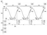
도 3은, 도 1 및 도 2의 실시예에 따른, 제어시스템을 포함하는 놀이기구의 구역 또는 영역(50)의 대락적인 측면도를 도시한다. 이러한 실시예에서, 영역(50)은 최초 하향부(52), 전이 오목면(transitional concave) 또는 계곡부(valley portion)(54), 및 이후의 상향부(56) 및 마지막의 약간 기울어진 부분(58)을 포함한다. 도시된 부분들 및 만곡부들은 단지 예시이며, 다양한 각도들의 상향, 하향 수평부 및 전이부들의 다양한 다른 배열들 또한 가능하다.Fig. 3 shows an enlarged side view of a zone or
차량(13) 및 채널(12)은 도 3의 상향부(56)에 도시된다. 채널(12)은 또한 수평부 또는 상향 만곡부를 형성할 수 있었다는 것이 인정될 것이다. 채널(12)은 측벽들(16) 없이 도시되었다. 센서들(A,B) 및 분사원들(20A,20B)의 위치 또한 개략적으로 도시되었다. 차량은 최초로 하향부(52)에서 하향이동을 하여, 외부 힘의 작용 없이 상향부(56)를 향하는 충분한 운동량을 가지고 있지 않는다는 것이 인정되어야 할 것이다. 외부 힘을 제공하기 위한 제어 시스템(37)의 작동은 도 1 내지 도 4c에 대한 참조와 함께 서술될 것이다.The
도 4a 내지 도 4c는 차량이 채널(12)을 따라 이동하는 3개의 다른 위치에서 차량(13)을 나타낸다. 예를 들어, 도 4a에 도시된 바와 같이, 도 3의 계곡부(54)에 상응하는 제1 위치에서, 차량(13)은 아직 센서(A)에 도달하지 않았다. 제어 시스템(37)은 아직 차량(13)을 검출하지 않았으며, 분사원들(20A,20B)은 유체를 분사하고 있지 않거나 낮은 압력과 적은 부피의 유체를 분사하고 있다.Figures 4A-4C show the
도 4b에서, 차량(13)의 전방 단부(22)는 바로 센서(A)를 통과하고 있다. 이러한 일이 일어나면, 센서들(A)은 차량(13)의 존재를 검출한다. 정보는 PLC(38)에 전달된다. 분사원들(20A)로부터 물 또는 공기와 같은 유체를 분사하도록 펌프(44)에 전원을 공급하기 위해 PLC(38)는 교대로 VFD(42)를 작동시킨다. 일부 실시예들에서, VFD(42)와 펌프(44)는 이미 작동되며, PLC(38)는 단지 밸브들만을 작동시킬 것이다. 동시에, 펌프(44)에 의해 퍼올려진 유체가 분사원들(20A)을 통해 분사되도록, PLC(38)는 분사원들(20A)과 관련된 밸브들(40)을 개방한다. 도 1에 대한 참조와 함께 서술된 바와 같이, 분사원들(20A)을 통해 분사된 유체(분사된 물일 수 있다)는 오목부(34)를 충격한다. 분사원(20A)으로부터 유체에 의해 전달된 힘은 차량(13)을 도 3에 도시된 상향부(56)로 밀어내기 위한 운동량을 제공한다. 도 4b의 위치에서, 차량(13)은 아직 센서(B)에 도달하지 않았으며, 따라서, 분사원들(20B)은 유체를 분사하고 있지 않다.In Figure 4b, the
도 4c에서, 차량의 전방 단부(22)는 센서(B)를 지났다. 이러한 일이 일어나면, 센서들(B)은 차량(13)의 존재를 검출한다. 정보는 PLC(38)에 전달된다. PLC(38)는 분사원(20A)으로부터 유체를 분사하도록 펌프(44)에 전원을 공급하기 위해 VFD(42)를 이미 작동시켰기 때문에, 일부 실시예들에서 PLC(38)가 VFD(42)와 통신하는 것은 불필요할 수 있다. 다른 실시예들에서, 부가적인 분사원들(20B)로부터 유체를 퍼올리기 위한 유체 압력을 증가시키기 위해, PLC(38)가 VFD(42)와 통신하는 것은 필수적일 수 있다. 어느 경우에도, 펌프(44)에 의해 퍼올려진 유체가 분사원들(20B)을 통해 분사되도록, PLC(38)는 분사원들(20B)과 관련된 밸브들(40)을 개방한다. 분사원들(20B)을 통해 분사된 유체는 또한 도 1에 대한 참조와 함께 서술된 오목부들(34)을 충격한다. 유체에 의해 분사원들(20B)로부터 전달된 힘은 또한 차량(13)을 도 3에 도시된 상향부(56)로 밀어내기 위한 운동량을 제공한다.In Fig. 4C, the
일부 실시예들에서, 분사원들(20A,20B)은 차량(13)을 상향부(56)로 및 기울어진 부분(58)으로 밀어내기 위한 충분한 운동량을 제공할 것이다. 다른 실시예들에서, 상향부(56)는 추가적인 운동량을 제공하기 위한 센서들 및 관련된 분사원들을 더 포함할 수 있다. 일부 실시예들에서, PL(38)는 정의된 길이의 시간에서 유체를 분사하기 위해 분사원들을 제어할 것이다. 일부 실시예들에서, 차량(13)이 이러한 센서들에 의해 검출되었을 때, 제어 시스템(37)은 물 분사 공급원들을 차단할 센서들을 더 포함할 것이다.In some embodiments,
일부 실시예들에서, 상향부(56)를 따라 센서들을 가지기 보다는, 영역(50)의 입구에 센서들이 있을 수 있다. 차량이 영역(50)에 진입하는 것이 검출되었을 때, 동시에 또는 차례대로, 센서들은 분사원들을 작동시킬 수 있다. 이러한 실시예에서, 분사원들은 특정한 기간의 시간 동안에 작동될 수 있거나 차량이 검출될 시 분사원들을 차단하기 위한 센서들이 영역(50)의 단부에 더 있을 수 있다.In some embodiments, rather than having sensors along the
일부 실시예들에서, 센서들은 생략될 수 있으며 차량이 운행을 시작한 후에 분사원들은 정의된 기간의 시간 동안에 작동된다. 다른 다양한 제어 장치들이 가능하다는 것이 인정될 것이다.In some embodiments, the sensors may be omitted and the minutes are activated for a defined period of time after the vehicle has started running. It will be appreciated that a variety of other control devices are possible.
일부 실시예들에서, 분사원들(20A,20B)은 고체 스트림 노즐 또는 분사 노즐일 수 있다. 노즐은 1/4인치 내지 2인치 범위의 직경을 가질 수 있다. 노즐의 각도는 0°내지 15°사이의 각도일 수 있다. 노즐들을 통한 흐름률은 분당 5 내지 50 갤런일 수 있다.In some embodiments, the
도 5a는 놀이기구(200) 부분의 개략도이다. 부분(200)은 슬라이드 경로(202), 제1 유체 시스템(204), 및 제어 시스템(206)을 포함한다.5A is a schematic view of a portion of the
도 1에 관하여 서술된 바와 같이, 슬라이드 경로는 측벽들 사이에 중앙 슬라이딩 표면을 가지는 수로 스타일 슬라이드와 같은 채널에 의해 정의될 수 있다. 종래의 수로타기와 같이, 슬라이딩 표면은 물로 윤활처리될 수 있거나 저마찰 코팅으로 이루어질 수 있다. 대안적으로 채널은, 차량이 떠오르거나, 차량이 휠들을 포함하거나, 구를 수 있거나, 다른 방법으로 이동할 수 있는, 충분한 유체가 있는 물이 채워진 채널일 수 있다. 미리 정해진 경로를 따라 차량의 안내를 지원하기 위해, 벽들은 슬라이딩 표면에 인접할 수 있거나 차량의 불확정된 경로로부터 더 멀리 이격될 수 있다. 도 5a에서, 슬라이딩 경로(202)가 프로파일로 도시된다. 예를 들어, 차량(208)은 고가(eleveated) 진입 지점(210)에서 출발한다. 슬라이딩 경로(202)는 진입 지점(210)으로부터 하방의 제1 계곡(212)까지, 상향의 제1 국부적인 피크(214)까지, 하방의 제2 계곡(216), 상방의 제2 국부적인 피크(218), 하방의 제3 계곡(220), 및 상향의 제3 국부적인 피크(222)의 경로가 있는 고저가 있는 경로이다. 이용된 탑승 프로필은 예시이며, 완전한 평면, 상방, 또는 하방을 포함하는, 다양한 다른 탑승 프로필들이 이용될 수 있다는 것이 이해될 것이다.As described with respect to FIG. 1, the slide path may be defined by a channel, such as a channel style slide, having a central sliding surface between the side walls. Like conventional waterway riding, the sliding surface can be lubricated with water or can be made of a low friction coating. Alternatively, the channel may be a channel filled with water with sufficient fluid, such that the vehicle may float, the vehicle may include, roll, or otherwise move. To support guidance of the vehicle along a predetermined path, the walls may be adjacent to the sliding surface or may be further away from the vehicle's undefined path. In Figure 5A, the sliding
이러한 실시예에서, 하나 이상의 제1, 제2, 및 제3의 계곡들(212,216,220) 각각은 제1, 제2, 및 제3의 배수구들(224,226,228)을 포함할 수 있거나, 슬라이딩 경로(202)의 이러한 상대적으로 낮은 영역들에 쌓일 수 있는, 물을 제거하기 위한 다른 수단들을 포함할 수 있다. 제1 계곡, 제2 및 제3 계곡들(212,216,220) 사이의슬라이딩 경로를 따라, 각각의 제1, 제2, 및 제3 국부적인 피크들(214,218,222)은 분사원들(230,232,234)의 뱅크들이다.In this embodiment, each of the one or more first, second, and
분사원들(230,232,234)의 뱅크들은 도 1에 서술된 분사원들(20A,20B)들과 동일한 방식으로 배열될 수 있다. 특히, 분사원들(220,232,234)들의 뱅크들은 슬라이드 경로(202)의 벽을 따라 이격된 각각의 분사원들을 구성할 수 있으며 반대편의 벽들을 따라 측면으로 정렬된 쌍들을 포함할 수 있다. 현재의 실시예에서, 슬라이드 경로(202)를 따라 차량을 추진하도록 차량에 힘을 작용하기 위해, 분사원들은 차량이 이동하는 방향을 향한 각도로 물을 안내하도록 각을 이룰 수 있다.The banks of the
이러한 실시예에서, 분사원들(230,232,234)의 제1, 제2, 및 제3 뱅크들은 제1, 제2, 및 제3 계곡들 사이의 경사 및 이들 각각의 제1, 제2, 및 제3 국부적인 피크들(214,218,222)의 사이의 경사를 따르는 중간 지점으로부터 대략적으로 각각의 제1, 제2, 및 제3의 국부적인 피크들(214,218,222)로 연장된다. 그러나, 분사원들(230,232,234)의 제1, 제2, 및 제3 뱅크들의 위치 뿐만 아니라 분사원들(230,232,234)의 제1, 제2 및 제3 뱅크들 내에서 분사기들 각각의 수와 위치는 다양하며 의도된 추진력 및 요구되는 기간에 종속될 것인데, 예를 들어, 슬라이드 경로(202)를 이동하는 차량이 상부로 이동하여 제1, 제2, 및 제3 국부적인 피크(214,218,222)를 넘어가기 위한 충분한 운동량을 가지는 것을 보증하는 것이다.In this embodiment, the first, second, and third banks of the
제1, 제2, 및 제3 분사원들(230,232,234)중 하나 또는 이들 모두는 미스터스(misters) 또는 워터캐논(water canon)과 같은, 특히, 다른 물 요구량을 가지는 다른 탑승 프로필들을 위한, 다른 탑승 피쳐들로 대체될 수 있다는 것이 인정되어야 할 것이다.One or both of the first, second, and
제1, 제2, 및 제3 배수구들(224,226,228) 및 분사원들(230,232,234)의 뱅크들은 슬라이드 경로(202)와 유체 시스템(204) 사이에 인터페이스를 제공한다.The banks of first, second, and
유체 시스템(204)은 놀이기구(200)에 의해 사용된 물을 돌린다. 유체 시스템(204)은 펌프(240)와 일련의 도관들을 포함한다. 도관들은 펌프(240)로부터 외부로 나가는 도관들과 물을 펌프(240)로 되돌리기 위한 되돌아오는 도관들 모두를 포함한다. 펌프(240)와 관련된 것들은, 예를 들어, 물이 증발되거나 놀이기구(200) 외부로 튀어나감으로 인해 물이 없어짐에 따라, 되돌아온 물이 슬라이드 경로(202)에 다시 퍼 올려져 유체 시스템(204)을 다시 채울 필요가 있을 때 까지 되돌아온 물을 축적하기 위한, 축적 탱크, 저장소, 또는 다른 물 공급원일 수 있다.The
현재의 실시예에서, 유체 시스템(204)은 주요 아웃고잉 도관(244)(outgoing conduit), 및, 제1, 제2, 및 제3 아웃고잉 도관(246,248,250)을 각각 포함한다. 주요 아웃고잉 도관(244)은 아웃고잉 도관들(246,248,250)의 각각의 지점과 유체적으로 연결된다. 주요 아웃고잉 도관(244)과 함께 제1 지점의 아웃고잉 도관(246)은 펌프(240)를 분사원들(230)의 제1 뱅크에 연결한다. 유사하게, 주요 이웃고잉 도관(244)과 함께 제2 지점 아웃고잉 도관(248)은 펌프(240)를 분사원들(232)의 제2 뱅크에 연결하며, 주요 아웃고잉 도관(244)과 함께 제3 지점 아웃고잉 도관(250)은 펌프(240)를 분사원들(234)의 제3 뱅크에 연결한다. 가압된 유체가 분사원들(230,232,234)의 제1, 제2, 및 제3 뱅크에 제공될 수 있는 다양한 수단들이 있다는 것이 인정될 것이다. 예를 들어, 주요 아웃고잉 도관(244)은 제거될 수 있었으며, 제1, 제2, 및 제3 지점 아웃고잉 도관들(246,248,250)은, 단일 펌프(240) 보다는, 별도의 펌프들에 직접 연결될 수 있었다.In the present embodiment, the
제1, 제2, 및 제3 지점 아웃고잉 도관들(246,248,250)은 또한, 각각, 제1, 제2, 및 제3 흐름 밸브들(254,256,258) 및 제1, 제2, 및 제3 체크 밸브들(260,262,264)을 포함할 수 있다. 현재의 실시예에서, 제1, 제2, 및 제3 체크 밸브들(260,262,264)은 주요 아웃고잉 도관(244)과 제1, 제2, 및 제3 흐름 밸브들(254,256,258) 사이에 있다. 다른 실시예에서, 대신에, 하나 이상의 체크 밸브들이 주요 아웃고잉 도관(244)에 제공될 수 있다. 일부 실시예들에서, 대신에, 제1, 제2, 및 제3 체크 밸브들(260,262,264)이 제1, 제2, 및 제3 흐름 밸브들(254,256,258)과 분사원들(230,232,234)의 뱅크들 사이에 각각 위치할 수 있다. 제1, 제2, 및 제3의 흐름 밸브들(254,256,258) 및 제1, 제2, 및 제3 체크 밸브들(260,262,264)의 개방과 폐쇄는 아래에 부가적으로 서술된 바와 같은 제어 시스템(206)에 의해 제어될 수 있다.The first, second, and third point outgoing conduits 246,248, 250 also include first, second, and
제1, 제2, 및 제3 배수구들(224,226,228)은 되돌아오는 도관들(265)에 연결될 수 있으며, 되돌아오는 도관들의 채널은 배출된 물을 펌프(240) 또는 관련된 보관 탱크 또는 유체 공급원 또는 저장소(241)로 되돌아오게 한다.The first, second, and
슬라이드 경로(202)를 횡단하고 있는 차량(208)과 관련된 정보를 기록하고 전송하기 위해, 슬라이드 경로(202)를 따라 센서들이 제공될 수 있다. 이러한 실시예에서, 슬라이드 경로(202)의 진입 지점(210)에 출입 센서(270)가 제공된다. 제1, 제2, 및 제3 센서들(272,274,276)이 제1, 제2, 및 제3 국부적인 피크들(214,218,222) 각각에 제공된다. 출입 센서(270)와 제1 센서(272) 사이의 탑승 영역은 제1 구역(271)이고, 제1 센서(272)와 제2 센서(274) 사이의 탑승 영역은 제2 구역(273)이며, 제2 센서(274)와 제3 센서(276) 사이의 탑승 영역은 제3 구역(275)이다. 출입 센서, 제1 센서, 제2 센서, 및 제3 센서들(270,272,274,276)은 다양한 파라미터들을 측정할 수 있거나 참가자 또는 차량(208)의 특성을 측정할 수 있다. 예를 들어, 일부 실시예에서, 출입 센서, 제1 센서, 제2 센서, 및 제3 센서들(270,272,274,276)은 단지 위치만을 측정할 수 있거나 차량(208)의 통행만을 측정할 수 있다. 다른 실시예들에서, 하나 이상의 출입 센서, 제1 센서, 제2 센서, 및 제3 센서들(270,272,274,276)은 속도와 같은 다르고/다르거나 부가적인 파라미터들을 측정할 수 있다.Sensors may be provided along the
출입 센서, 제1 센서, 제2 센서, 및 제3 센서들(270,272,274,276)은 제어 시스템(206)의 일부를 형성한다. 제어 시스템(206)은 프로그램 가능한 논리 제어(PLC)(280)와 같은 제어기를 포함한다. 도 5a에서, PLC(280)는 광학 가변 주파수 구동기(VFD)(281)를 통해 펌프(240)에 연결되는 것으로 나타난다. 명확성을 위해, 제어 시스템의 다양한 요소들의 전기적 연결은 도 5b에 나타난다.The entry sensor, the first sensor, the second sensor, and the third sensors 270,272, 274, 276 form part of the
도 5에 도시된 바와 같이, 출입 센서, 제1 센서, 제2 센서, 및 제3 센서들(270,272,274,276)은 PLC(280)에 연결되어 있다. 제1, 제2, 및 제3 흐름 밸브들(254,256,258)은 또한 PLC(280)에 연결되어 있으며, 제어 시스템(206)의 일부로서, PLC(280)에 입력을 제공할 수 있고 PLC(280)로부터 출력을 수신할 수 있다. 제어 시스템(206)은 또한 PLC(280)에 연결된 사용자 인터페이스(284) 및 저장 장치(282)를 포함할 수 있다. PLC(280)는 펌프(240)에 직접 연결될 수 있거나 가변 주파수 구동기(VFD)(281)을 통해 펌프(240)에 연결될 수 있다. 특히, 펌프 출력이 요구된 레벨에 이르도록 밸브들을 개방하고 폐쇄하는 동안에, VFD(281)는 펌프의 작동을 조정하기 위해 사용될 수 있다. PLC(280)를 제어 시스템에 다른 요소들에 연결하는 것은 단지 개략적으로만 도시되어 있다. 무선 연걸을 포함하는 가능성 있는 다양한 연결 구조들이 있다는 것이 인정될 것이다. 일부 실시예들에서, VFD는 기계적인 콘트랙터(contractor)와 같은 직접적인 연결선(DOL) 장치로 대체될 수 있다. 그러한 콘트랙터는 PLC(280)의 제어에 기초하여 펌프(240)에 전력을 제공하기 위한 계전기(relay)로서 역할을 할 수 있다.As shown in FIG. 5, the entrance sensor, the first sensor, the second sensor, and the
탑승기구가 탑승자 없이 많은 시간 동안 운행할 수 있을 때의 휴지기 동안, 펌프(240)의 속력은 에너지를 절약하도록 조정될 수 있다. 기계적인 시스템 전체의 물의 균형에는 영향을 주지 않으나, 에너지 소비를 줄이는 것과 소음을 줄이는 것을 실현할 수 있는 낮은 비율의 유체흐름이 되도록, 펌프(240)의 출력이 낮추어질 수 있다. 시스템이 정상적인 작동으로 다시 돌아올 필요가 있을 때, 작동자가 버튼을 누르거나 사용자 인터페이스(284)를 통하여 정상적인 작동으로 돌아오는 것이 가장 가능성이 있다. 어떠한 방식으로든지, 시스템은 등록된 작동자에게, 예를 들어, 적색/녹색 신호기 시스템, 또는 슬라이드 피쳐로의 붐 게이트 접근 제한과 같은 시각적 지시자를 사용하는 것이 안전한지 여부를 알려준다.During a rest period when the riding apparatus can run for many hours without an occupant, the speed of the
작동의 하나의 예시적 모드에서, 제1, 제2, 및 제3 흐름 밸브들(254,256,258)은 초기에는 폐쇄되어 있어 물이 분사원들(230,232,234)의 제1, 제2, 및 제3 뱅크들을 통해 흐르지 않을 것이다. 물이 외부로 흐르는 방향에 있는 펌프(240)로부터 제1, 제2, 및 제3 밸브들(254,256,258)로 흐를 수 있지만 이의 반대방향으로는 흐르지 않도록, 제1, 제2, 및 제3 체크 밸브들(260,262,264)이 배향된다.In one exemplary mode of operation, the first, second, and
차량(208)은 물 윤활 슬라이드 경로(202)의 출입 센서(270)를 지나쳐 슬리이딩할 것이다. 출입 센서(270)는 차량의 존재를 등록할 것이며 이를 PLC(280)에 전달할 것이다. PLC(280)는 VFD(282)를 통하여 펌프(240)를 작동시킬 것이다. PLC는 또한 퍼 올려진 물이 주요 아웃고잉 도관(244) 및 제1 지점 도관(246)을 통하여 이동하도록 제1 흐름 밸브(254)를 개방할 것이다. 물은 제1 흐름 밸브(254)를 통해 퍼올려지며 분사원들(230)의 제1 뱅크를 통하여 나갈 것이다. 그 동안에, 차량(208)은 제1 계곡(212) 안으로 연속적으로 슬라이딩하여 내려가며, 이후에, 상부의 제1 국부적인 피크(214)로 향한다. 차량(208)이 상부로 이동함에 따라, 차량(208)의 속도는 느려질 것이다. 도 1 내지 도 4에 관하여 전술한 바와 같이, 차량(208)이 분사원들(230)의 제1 뱅크를 지나쳐 이동할 때, 분사원들(230)의 뱅크는 차량(208)에 대하여 물을 분사할 것이며 차량(208)을 제1 국부적인 피크(214)로 밀어내는 데 도움이 되는 힘을 제공할 것이다.The
차량(208)이 제1 국부적인 피크(214)를 지나 이동함에 따라, 차량(208)은 제1 센서(272)를 지난다. 제1 센서(272)는 차량(208)의 존재를 등록할 것이며 이를 PLC(280)에 전달할 것이다. PLC(280)는, 예를 들어, 물의 흐름률과 압력이 증가하도록, VFD(281)에 의해 펌프에 공급된 전원의 주파수의 상승을 통해, 펌프(240)의 펌프율을 증가시킬 수 있다. PLC(280)는 또한 퍼올려진 물이 주요 아웃고잉 도관(244) 및 제2 지점 도관(248)을 통해 이동할 수 있도록 제2 흐름 밸브(256)를 개방할 것이다. 물은 제2 흐름 밸브(256)를 통해 퍼올려질 것이며 분사원들(232)의 제2 뱅크를 통해 나갈 것이다. 그 동안에, 차량(208)은 제2 계곡(216) 안으로 연속적으로 슬라이딩하여 내려가며, 이후에, 상부의 제2 국부적인 피크(218)로 향한다. 차량(208)이 상부로 이동함에 따라, 차량(208)의 속도는 느려질 것이다. 차량(208)이 분사원들(232)의 제2 뱅크를 지나쳐 이동할 때, 분사원들(232)은 차량(208)에 대하여 물을 분사할 것이며 차량(208)을 제2 국부적인 피크(218)로 밀어내는 데 도움이 되는 힘을 제공할 것이다.As the
동시에, 차량(208)이 분사원들(230)의 제1 뱅크를 지났기 때문에, 물 요구량과 에너지 소비를 줄이기 위해, 이러한 공급원들로부터의 흐름은 중단될 수 있다. 이를 위해, PLC(280)는 제1 흐름 밸브(254)를 폐쇄한다. 제1 흐름 밸브(254)를 폐쇄하는 시간은 바로 차량(208)이 제1 국부적인 피크(214)를 통과한 이후일 수 있거나 제1 흐름 밸브(254)를 폐쇄하는 시간은 연기될 수 있다. 예를 들어, 제1 지점 도관(246) 내의 수압 및 제1 흐름 밸브(254)의 물의 흐름률에 따라, 제1 흐름 밸브(254)를 즉시 폐쇄하면 수압으로 인해 제1 흐름 밸브(254)가 손상될 수 있다. PLC(280)는, 제2 흐름 밸브(256)의 개방으로부터, 또는 VFD를 통해 PLC(280)에 의한 펌프 출력(240)의 조정으로부터, 제1 지점 도관(246) 내 압력이 낮아질 때 까지 대기할 수 있다. 일부 실시예들에서, 제1 지점 도관(246) 내 압력이 미리 정해진 레벨에 도달했을 때 제1 흐름 밸브(254)가 자동으로 폐쇄되도록, 제1 흐름 밸브(254)는 독립적으로 작동할 수 있다. 다른 실시예들에서, 제1 흐름 밸브(254) 또는 제1 지점 도관(246) 내 센서는 PLC(280)에 피드백을 제공할 수 있으며, PLC는 제1 흐름 밸브(254)의 폐쇄를 제어할 수 있다.At the same time, since
도관들은 또한 하나 이상의 압력 완화 또는 방출 밸브들(253)을 포함할 수 있다. 비록 단일의 압력 완화 밸브(253)가 주요 아웃고잉 도관(244)에 도시되었다고 하더라도, 그러한 압력 완화 밸브들은 밸브가 전환되는 동안에 과도한 압력을 완화시킬 필요가 있는 시스템 전체에 걸쳐서 설치될 수 있으며 흐름 밸브들이 개방위치와 폐쇄 위치의 전방 및 후방으로 전환되는 동안에 흐름 밸브들(254,256,258)에 가해지는 손상을 감소시킬 수 있다는 것이 인정되어야 하 것이다.The conduits may also include one or more pressure relief or discharge
다른 실시예들에서, 제1 흐름 밸브들(254)의 폐쇄는, 도관의 크기와 길이, 펌프 압력 및 부피, 제2 흐름 밸브의 개방 및 특정한 시스템을 디자인하는 데 이용된 알려진 다양한 다른 시스템에 기초한, 흐름의 계산 또는 측정에 기초하여 설정된 타이머에 의해 제어될 수 있다. 탑승 참가자들이 미리 정해진 간격으로 탑승 기구에 탑승하면, 예를 들어, 컨베이어 벨트, 또는 푸시 버튼 적재 제어 참가자 도입률을 이용하여, 참가자들이 탑승하는 시간을 알 수 있으며 밸브들의 작동을 제어할수 있다. 밸브들은 또한 운영자에 의해 제어될 수 있다.In other embodiments, the closure of the
일부 실시예들에서, 제1 흐름 밸브(254)는 완전히 폐쇄되지 않을 수 있으며, 그러나, 대신에, 분사원들(230)의 제1 뱅크로 흐르는 물의 감소된 흐름을 유지하도록, 부분적으로 개방될 수 있다. 제1 흐름 밸브(254)가 완전히 폐쇄된 경우 조차도, 제1 체크 밸브(260)는 물이 제1 체크 밸브(260)를 통하여 역으로 방출되는 것을 방지할 것이다. 제1 체크 밸브(260)는 또한 제1 흐름 밸브(254)의 다른 측면에 위치될 수 있거나 생략될 수 있다. 유체 시스템(204) 내에서 물의 흐름과 보유를 조절하는 것을 지원하기 위해, 체크 밸브들은 또한 유체 시스템(204) 내 다른 곳에 있을 수 있다.In some embodiments, the
차량(208)이 제2 국부적인 피크(218)로 이동함에 따라, 차량(208)은 제2 센서(274)를 지나간다. 제2 센서(274)는 차량(208)의 존재를 등록할 것이며 이를 PLC(280)에 전달할 것이다. PLC(280)는 (만일 존재한다면) VFD(281)를 통하여 펌프(240)의 펌프율과 같은 파라미터들을 증가시키거나, 그렇지 않으면, 파라미터들을 조정할 수 있다. PLC는 또한 퍼올려진 물이 주요 아웃고잉 도관(244) 및 제3 지점 도관(250)을 통해 이동하도록 제3 흐름 밸브(258)를 개방할 것이다. 물은 제3 흐름 밸브(258)를 통하여 퍼올려질 것이며 분사원들(234)의 제3 뱅크를 통해 방출될 것이다. 그 동안에, 차량(208)은 연속적으로 슬라이드하여 제3 계곡(228)으로 내려가며, 이후에, 제3 국부적인 피크(222)를 향하여 올라간다. 차량(208)이 상부로 이동함에 따라, 차량(208)의 속도는 느려질 것이다. 차량(208)이 분사원들(234)의 제3 뱅크에 도달하면, 분사원들(234)은 차량(208)에 대하여 물을 분사할 것이며 차량(208)을 상부의 제3 국부적인 피크(222)로 밀어내는 데 도움을 주는 힘을 제공할 것이다.As the
제1 흐름 밸브(254)에 비교하는 방식으로, 흐름 시스템(204) 내 물의 양을 유지하게 위해 제1 체크 밸브(260)에 비교하는 방식으로 작동하는 제2 체크 밸브(262)와 함께, 제2 흐름 밸브(256)는 부분적으로 또는 완전하게 폐쇄되어 있을 것이다.With a
차량(208)이 제3 국부적인 피크(222)를 넘어 이동함에 따라, 차량(208)은 제3 센서(276)를 지난다. 제3 센서(276)는 차량(208)의 존재를 등록할 것이며 이를 PLC(280)에 전달할 것이다. 제1, 및 제2 흐름 밸브들(254,256)에 비교하는 방식으로, 제3 흐름 밸브(258)는, 흐름 시스템(204) 내에서 물의 양을 유지하기 위해 제1 및 제2 체크 밸브들(260,262)과 비교하는 방식으로 작동하는 제3 체크 밸브(264)와 함께, 부분적으로 또는 완전히 폐쇄되어 있다.As the
유체(204) 및 제어 시스템(206) 각각의 작동 전반에 걸쳐서, 제1, 제2, 및 제3 계곡들(212,216,220)에 축적된 물은 제1, 제2, 및 제3 배수구들(224,226,228)을 통해 배수될 수 있으며 되돌아가는 도관들(265)을 통해 펌프(240)로 되돌아갈 수 있다.The accumulated water in the first, second, and
체크 밸브들(260,262,264)의 사용은, 일단 밸브들(254,256,258)이 개방되면, 분사원들(230,232,234)의 뱅크들 내에서 요구된 압력과 흐름률을 달성하기 위한 시간을 감소시킬 수 있다는 것이 인정되어야 할 것이다. 지점 흐름 도관들(246,248,250) 내에서 충분한 압력이 달성될 때, 밸브들(254,256,258)은 자동으로 개방될 타입일 수 있으며, 압력이 특정한 레벨 아래로 떨어질 때, 밸브들(254,256,258)은 자동으로 폐쇄될 타입일 수 있다. 부가적인 체크 밸브들이 분사원들에 인접하여 설치될 수 있다. 각각의 분사원들은 물을 분사원들에 인접한 도관들 내에 보관하기 위한 전용 체크 밸브를 가질 수 있으며, 분사원들은 개별적인 노즐들일 수 있다. 밸브들(254,256,258)은 시스템 요구사항들에 따라 서로 다른 압력 레벨들에 반응할 수 있다.It should be appreciated that the use of
비록 배수구들(224,226,228)이 도시되었다고 하더라도, 배수구들의 수와 위치는 시스템 요구사항들에 따라 변경되거나 생략될 수 있다. 또한, 배수구들은, 되돌아오는 도관들(265)에 연결되지 않을 수 있고, 물을 다시 채우기 위해 물을 주변 환경 또는 저장소(241) 또는 시스템의 다른 영역들에 배출할 수 있다.Even though the
도시된 센서들(270,272,274,276)은 차량(208)의 존재를 측정한다. 센서들(208)은 더 많은 장소 또는 다른 장소에 위치할 수 있으며 또한 속도와 같은 다른 정보를 측정할 수 있다. 예를 들어, 만일 하나 이상의 센서들이 분사원들(230)의 뱅크 이전의 상향부에 위치한다면, 차량(208)을 제1 국부적인 피크(272)로 밀어올리도록, 분사원들을 작동시킬 시간과 분사원들(230)의 뱅크에 의해 요구되는 물의 부피와 압력을 계산하기 위해, 측정된 차량의 속도가 PLC(280)에 의해 이용될 수 있다. 이후에, PLC(280)는 계산된 요구사향들에 따라 VFD(282)와 펌프(240)를 작동할 수 있다.The illustrated
유체 흐름 시스템(204)은 물을 필요로 할 때에만, 예를 들어, 차량이 존재할 때, 탑승부(200)의 영역들에 물을 공급함으로써 물의 필요량을 감소시키는 수단을 제공한다는 것이 인정되어야 할 것이다. 유체 흐름 시스템(204)은 PLC(280) 구동 제어 시스템(예를 들어, 밸브들의 개방과 폐쇄가 차량이 탑승부(200)를 횡단하는데 걸리는 시간의 측정에 기초한 타이머에 의해 제어된다) 없이 작동될 수 있다. 대안적으로, 밸브들은 차량이 특정 위치에 인접할 때 작동하는 접근 탐지기에 의해 직접 제어될 수 있다.It should be appreciated that the
일부 실시예들에서, 각각의 구역들(271,273,275)을 위한 압력 요구사항들은, 20 내지 60 PSI에서 각각의 구역(예시적인 3개의 구역들에 대해서는 1500 내지 9000의 분당 갤런(gallons per minute, GPM)의 흐름률)에 대한, 500 내지 3000 GPM의 흐름률이다.In some embodiments, the pressure requirements for each of the
일부 실시예들에서, PLC(280)는 분석될 수 있고, 예를 들어, 탑승 효율을 증가시키기 위한, 이용될 수 있는 데이터를 기록하고 저장할 수 있다.In some embodiments, the
(예를 들어, 탑승자가 존재하거나, 또는 라이드 피쳐 표면을 냉각시키고 온도를 유지할 때와 같은) 필요할 때에만 물을 공급하는 것이 바람직할 때, 유체 흐름 시스템(204)과 제어 시스템(206)은 완전히 다른 워터 라이드 피쳐와 함께 사용되어 어떠한 환경에서도 이용될 수 있다는 것을 인정되어야 할 것이다.The
도 5a의 도관 구조는 도관들(246,248,250)의 평행한 시스템을 나타낸다. 이러한 구조는 도 6에 도시된 바와 같은 도관들(244B,246B,248B,250B)이 연속으로 있는 흐름 시스템(204B)으로 대체될 수 있다. 시스템은 흐름 밸브들 (254B,256B, 258B)과 체크 밸브들(260B,262B,264B)을 포함한다. 도 6의 흐름 시스템(204B)은 도 5a의 흐름 시스템(204)을 대체할 수 있다. 되돌아오는 도관들이 도 6에서는 생략되어 흐름 시스템의 일부를 형성할 수 있다는 것이 주목될 것이다. 그러한 일련의 구성에서, 흐름 밸브(254B)가 개방될 때에만 유체는 도관(248)으로 흐를 것이며, 두 개의 밸브들(254B,256B)이 모두 개방될 때에만 유체는 도관(250B)로 흐를 것이다. 이는 도 5a의 흐름 밸브(254)의 폐쇄가 유체가 도관(248) 또는 도관(250)으로 흐르는 것을 차단하지 않을 때의 시스템과는 대조적이다.The conduit structure of FIG. 5A represents a parallel system of conduits 246,248, and 250. FIG. This structure can be replaced by a flow system 204B in which the
PLC 제어 시스템이 있는 유체 흐름 시스템 또는 PLC 제어 시스템이 없는 유체 흐름 시스템이 워터 라이드 이외의 다른 장치들에 이용될 수 있다. 도 7a는 물놀이 구조(300A)를 도시한다. 물놀이 구조(300A)는 스프링 클러 및 물 분사기와 같은 다양한 유체 피쳐들(330A,332A,334A)(예를 들어, 물)을 포함할 수 있다. 워터 피쳐들(330A,332A,334A) 각각과 관련된 것들은 각각의 접근 탐지기 또는 다른 센서들(370A,372A,374A)이다. 물놀이 기구(300A)의 물 소비를 줄이기 위해, 물놀이 기구(300A)는 펌프(340A), 아웃고잉 흐름 도관(244A), 지점 흐름 도관들(346A,348A,350A), 및 지점 흐름 도관들(346A,348A,350A) 내에 흐름 밸브들(354A,356A,358A)을 포함하는 유체 흐름 시스템(304A)을 포함할 수 있다.A fluid flow system with a PLC control system or a fluid flow system without a PLC control system may be used for other devices than the water rides. FIG. 7A shows the
펌프(340)의 작동에 있어서, 펌프(340)는 도관들(344A,346A,348A,350A) 내 압력을 유지한다. 밸브들(354A,356A,358A)은 개방 위치와 폐쇄 위치 사이에서 이동할 수 있으며 또한 개방 위치와 폐쇄 위치의 중간 위치에서 유지될 수 있다. 각각의 워터 피쳐(330A,332A,334A)에 인접한 데에서 참가자들이 검출될 때, 밸브들(354A,356A,358A)은 개방된다. 각각의 워터 피쳐(330A,332A,334A)에 인접한 참가자들이 검출되지 않을 때, 밸브들(354A,356A,358A)은 폐쇄된다. 밸브들(354A,355A,358A)의 개방과 폐쇄는 또한, 예를 들어, PLC를 이용한, 제어 시스템에 의해 제어될 수 있다. 도 5a, 도 5b, 및 도 6과 관련되어 서술된 다양한 실시예들 및 변형들이 본 실시예와 동일하게 적용된다.In operation of the pump 340, the pump 340 maintains the pressure in the
도 7b는 중력에 기초한 워터 슬라이드 구조(300B)를 도시한다. 워터 슬라이드 구조(300B)는 들어가는 단부(331B)와 나가는 단부(333B)를 가지는 슬라이딩 표면(329B)을 포함한다. 워터 슬라이드 구조(300B)는 또한 들어가는 단부(331B)로부터 나가는 단부(333B)까지 슬라이드 경로를 따르는 다양한 지점들에 복수의 물 공급원들(330B,332B,334B)을 포함한다.Figure 7B shows a
물 공급원들(330B,332B,334B) 각각과 관련하여, 물 공급원들(330B,332B, 334B) 각각은 접근 탐지기들 또는 다른 센서들(370B,372B,374B)이다. 워터 슬라이드 구조(300B)의 물 소비를 줄이기 위해, 물놀이 기구 구조(300B)는 펌프(340B), 외부로 나가는 흐름 도관(244B), 지점 흐름 도관들(346B,348B,350B), 및 지점 흐름 도관들(346B,348B,350B) 내의 흐름 밸브들(354B,356B,358B)을 포함하는 유체 흐름 시스템(304B)을 포함할 수 있다.With respect to each of the
펌프(340B)의 작동에서, 펌프(340B)는 도관들(344B,346B,348B,350B) 내 압력을 유지한다. 참가자가 각각의 물 공급원들(330B,332B,334B)에 다가오는 것이 검출될 때, 밸브들(354B,356B,358B)은 개방되어 있다. 지정된 시간이 경과된 이후에 밸브들(354B,356B,358B)은 폐쇄된다. 시간은 워터 슬라이드를 따라 슬랑이딩을 하는 예상되는 참가자들의 비율에 기초하여 설정될 수 있다. 밸브들(354A,355A,358A)의 개방과 폐쇄는또한 제어 시스템, 예를 들어, PLC를 이용하여 제어될 수 있다. 도 5a, 5b 및 6과 관련된 다양한 실시예들과 변형들이 현재의 실시예와 동일하게 적용된다.In operation of the
수직 터빈 펌프, 원심 펌프, 및 잠수 펌프와 같은 다양한 펌프 타입들이 시스템 요구 사항에 따라 사용될 수 있다. 밸브들은 솔레노이드로 제어되는 밸브들 또는 공압 밸브 또는 임의의 자동화된 수단에 의해 제어되는 밸브들일 수 있다. 밸브들로부터의 피드백 신호는, 이산값(개방 또는 폐쇄) 및 밸브를 중간 위치에서 유지하기에 적합한 아날로그 값(개방되거나 폐쇄된 정도)중 어느 하나로, PLC와 같은 제어 시스템에 밸브 위치에 대한 정보를 줄 수 있다.Various pump types such as vertical turbine pumps, centrifugal pumps, and submersible pumps can be used according to system requirements. The valves may be solenoid-controlled valves or valves controlled by pneumatic valves or any automated means. The feedback signal from the valves provides information about the valve position to a control system, such as a PLC, with either a discrete value (open or closed) and an analog value (open or closed degree) suitable for holding the valve in an intermediate position You can give.
일부 실시예들에서, 단일 펌프와 제어기는 하나 또는 복수의 탑승을 위해 사용될 수 있다. 다른 실시예들에서, 펌프들과 물이 배출되는 위치 사이의 도관의 길이를 감소시키기 위해, 단일 제어기는 탑승 기구 주변에 분산되어 있는 복수의 펌프들을 제어할 수 있다.In some embodiments, a single pump and controller may be used for one or more of the boarding. In other embodiments, a single controller may control a plurality of pumps dispersed around the boarding device to reduce the length of the conduit between the pumps and the location where the water is discharged.
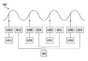
일부 실시예들에서, 도 8a에 도시된 바와 같이, 제어는 또한 부분적으로 또는 전체적으로 분산될 수 있다. 특히, 놀이기구 라이드 피쳐(400)를 위해, 복수의 저장소(441A,441B,441C,441D)로부터 놀이기구 라이드 피쳐(400)로 물을 퍼올리기 위한 복수의 펌프(440A,440B,440C,440D)를 구동하는 복수의 VDF(481A,481B,481C, 481D)를 제어하기 위한 단일의 PLC(480)가 이용된다. 이러한 실시예에서, 밸브들이 생략될 수 있다. 펌프(440A,440B,440C,440D)의 펌프속력은 밸브의 필요 없이 PLC(480)에 의해 직접 조정될 수 있다.In some embodiments, as shown in Figure 8A, the control may also be partially or wholly distributed. 440B, 440C, 440D for pumping water from the plurality of
전술한 바와 같이, 일부 실시예들에서, 밸브들은 제거될 수 있으며, 흐름 제어가 별도의 펌프들 및 관련된 VFD들의 쌍에 의해 제공된다. 도 8b는 그러한 놀이공원 탑승 기구 부분(500)의 개략도이다. 부분(500)은 슬라이드 경로(502), 유체 시스템(504), 및 제어 시스템(506)을 포함한다.As described above, in some embodiments, the valves may be removed and the flow control is provided by a pair of separate pumps and associated VFDs. FIG. 8B is a schematic view of such amusement
도 1 및 도5a에 관하여 서술된 바와 같이, 측벽들 사이의 슬라이드 경로는 중앙의 슬라이딩 경로를 가지는 수로 스타일의 슬라이드와 같은 채널에 의해 정의될 수 있다. 슬라이딩 표면은 물로 윤활처리될 수 있으며, 종래의 수로타기와 같이, 저마찰 코팅으로 이루어질 수 있다. 대안적으로, 채널은, 차량이 떠오르거나 차량이 휠들을 포함하고 구를 수 있거나 다른 방법으로 이동하는, 유체가 충분한 물로 채워진 채널일 수 있다. 미리 정해진 경로를 따라 차량의 안내를 지원하기 위해, 벽들은 슬라이딩 표면에 인접할 수 있거나 차량의 불확정된 경로로부터 더 멀리 이격될 수 있다.As described with respect to Figures 1 and 5a, the slide path between the side walls may be defined by a channel, such as a channel style slide with a central sliding path. The sliding surface can be lubricated with water and can be made of a low friction coating, such as conventional water riding. Alternatively, the channel may be a channel in which the fluid is filled with sufficient water, in which the vehicle floats or the vehicle includes the wheels and can move or otherwise move. To support guidance of the vehicle along a predetermined path, the walls may be adjacent to the sliding surface or may be further away from the vehicle's undefined path.
도 8a에서, 슬라이드 경로(502)는 프로파일로 도시되어 있다. 예를 들어, 차량(508)은 높이 올려진 진입 지점(510)에서 출발한다. 슬라이드 경로(502)는 진입 지점(510)으로부터 제1 계곡(512)까지 하향 경로, 제1 국부적인 피크(514)까지 상향 경로, 제2 계곡(516)까지 하향 경로, 제2 국부적인 피크(518)까지 상향 경로, 제3 계곡(520)까지 하향 경로, 제3 국부적인 피크(522)까지 상향 경로로 이루어진 높낮이가 있는 경로이다. 라이드 프로필은 예시이며, 완전히 평평하거나 상향 또는 하향 프로필을 포함하는, 다양한 다른 라이드 프로필들이 이용될 수 있다는 것이 이해될 것이다.8A,
이러한 실시예에서, 하나 이상의 제1, 제2, 및 제3 계곡들(512,516,520) 각각은 제1, 제2, 및 제3 배출구들(524,526,528)을 포함할 수 있거나 슬라이드 경로(502)의 이러한 상대적으로 낮은 영역들에 축적되는 물을 제거하는 다른 수단들을 포함할 수 있다. 슬라이드 경로를 따르는 제1, 제2, 및 제3 계곡들(512,516, 520) 및 각각의 제1, 제2, 및 제3 국부적인 피크들(514,518,522)사이는 하나 이상의 분사원들(530,532,534)의 하나 이상의 뱅크들이다.In this embodiment, each of the one or more first, second, and
분사원들(530,532,534)의 뱅크들은 도 1에 관해 서술된 분사원들(20A,20B)과 동일한 방식으로 배열될 수 있다. 특히, 분사원들(530,532,534)의 뱅크들은 슬라이드 경로(502)의 벽들을 따라 이격된 각각의 분사원들로 구성될 수 있으며 반대편 벽들을 따라 측면으로 정렬된 쌍들을 포함할 수 있다. 현재의 실시예에서, 슬라이드 경로(502)를 따라 차량에 추진력을 가하여 차량을 이동시키는 방향을 향하여 물을 보내기 위해, 분사원들은 각을 이룰 수 있다.The banks of
이러한 실시예에서, 분사원들의 제1, 제2, 및 제3 뱅크들(530,532,534)은 제1, 제2, 및 제3 계곡들(512,516,520)과 각각의 제1, 제2, 및 제3 국부적인 피크들(514,518,522) 사이의 경사를 따르는 중간 지점으로부터 대략 각각의 제1, 제2, 및 제3 국부적인 피크들(514,518,522)까지 연장된다. 그러나, 분사원들(530,532,534)의 제1, 제2, 및 제3 뱅크들의 위치 뿐만 아니라 분사원들(230,232,234)의 제1, 제2, 및 제3 뱅크들 내 각각의 분사기들의 수와 위치는 다양할 것이며 바람직한 추진력 및, 예를 들어, 슬라이드 경로(502)를 따라 이동하는 차량이 제1, 제2, 및 제3 국부적인 피크들(514,518,522)의 상부로 이동하여 넘어가기에 충분한 운동량을 가지는 것을 보증하기 위한, 지속시간에 종속될 것이다.In this embodiment, the first, second, and
제1, 제2, 및 제3 분사원들(530,532,534)의 하나 또는 모두는 미스터스(misters) 또는 워터 캐논들(water cannons), 특히, 물의 필요량이 다른 라이드 프로필들과 같은 다른 라이드 피쳐들로 대체될 수 있다는 것이 인정되어야 할 것이다.One or both of the first, second, and
제1, 제2, 및 제3 배출구들(524,526,528) 및 분사원들(530,532,534)의 뱅크들은 슬라이드 경로(502)와 유체 시스템(504) 사이에 인터페이스를 제공한다.The banks of the first, second, and
유체 시스템(504)은 놀이공원 탑승기구(500)에 의해 사용된 물을 이동시킨다. 유체 시스템(504)은 제1, 제2, 및 제3 펌프들(540A,540B,540C), 물 공급원(541), 및 일련의 도관들을 포함한다. 도관들은 펌프들(540A,540B,540C)로부터 분사원들(530,532,534) 각각의 뱅크들로 가는 제1, 제2, 및 제3 아웃고잉 도관들 (546,548,550)과 물을 물 공급원(541)으로 되돌리기 위한 되돌아오는 도관들(565) 모두를 포함한다. 일부 실시예들에서, 각각의 워터 피쳐와 관련된 하나 이상의 펌프가 있을 수 있다. 예를 들어, 만일 분사원들(534)의 뱅크가 (도 3의 분사원들(20A,20B) 당) 두 개 영역의 그룹으로 이루어져 있었다면, 각각의 영역에 대해 개별적인 펌프가 사용될 수 있었거나, 하나의 펌프가 양쪽 모두의 영역에 사용될 수 있었다.The
제1 아웃고잉 도관(546)은 물 공급원(541) 및 제1 펌프(540A)에 유체적으로 연결되어 있다. 유사하게, 제2 아웃고잉 도관(548)은 물 공급원(541)에 유체적으로 연결되어 있으며, 제2 펌프(540B)와 제3 아웃고잉 도관(550)은 물 공급원(541)과 제3 펌프(540C)에 유체적으로 연결되어 있다. 제1, 제2, 및 제3 아웃고잉 도관들(546,548,550) 각각은 제1, 제2, 및 제3 펌프들(540A,540B,540C) 각각을 분사원들(530,532,534)의 제1, 제2, 및 제3 뱅크들 각각에 연결한다. 유체 연결이 제1, 제2, 및 제3 펌프들(540A,540B,540C)로부터 분사원들(530,532,534)의 제1, 제2, 및 제3 뱅크들에 제공될 수 있었던 다양한 수단들이 있다는 것이 인정될 것이다. 또한, 제1, 제2, 및 제3 펌프(540A,540B,540C) 각각은 단일의 물 공급원(541) 보다는 별도의 물 공급원들에 연결될 수 있었다.The first
각각의 제1, 제2, 및 제3 지점 아웃고잉 도관(546,548,550)은 또한 제1, 제2, 및 제3 흐름 센서들(554,556,558) 및 제1, 제2, 및 제3 체크 밸브(560,562,564) 들을 포함할 수 있다. 흐름 센서들(546,548,550)은 각각의 아웃고잉 도관들(546,548,550) 상의 그레이드(grade) 위에 위치한다. 현재의 실시예에서, 제1, 제2, 및 제3 체크 밸브들(560,562,564)은 제1, 제2, 및 제3 펌프들(540A,540B, 540C)과 제1, 제2, 및 제3 흐름 센서들(554,556,558) 사이에 위치한다. 다른 실시예들에서, 대신에 하나 이상의 체크 밸브들이 물 공급원(541) 또는 분사원들(530,532,534) 각각의 뱅크들에 인접하여 제공될 수 있다.Each of the first, second, and third point outgoing conduits 546,548,550 also includes first, second, and third flow sensors 554,556,558 and first, second, and third check valves 560,562,564, Lt; / RTI >
제1, 제2, 및 제3 배출구들(524,526,528)은 배출된 물을 되돌아오게 하는 채널로 이루어진 되돌아오는 도관들(565)을 펌프들(540A,540B,540C) 또는 관련된 저장 탱크 또는 저장소(541)에 연결한다.The first, second, and
슬라이드 경로(502)를 횡단하는 차량(508)과 관련된 정보를 기록하고 전송하기 위해, 슬라이드 경로(502)를 따라 센서들이 제공될 수 있다. 이러한 실시예에서, 진입 센서(570)가 슬라이드 경로(502)의 진입 지점(510)에 제공된다. 각각의 제1, 제2, 및 제3 피쳐 센서들(572,574,576)이 각각의 제1, 제2, 및 제3의 국부적인 피크들(514,518,522)에 제공된다. 진입 센서(570)와 제1 피쳐 센서(572) 사이의 탑승 영역은 제1 구역(571)이고, 제1 피쳐 센서(572)와 제2 피쳐 센서(574) 사이의 탑승 영역은 제2 구역(573)이며, 제2 피쳐 센서(574)와 제3 피쳐 센서(576) 사이의 탑승 영역은 제3 구역(575)이다. 진입 센서, 제1 센서, 제2 센서, 및 제3 센서들(570,572,574,576)은 참가자 또는 차량(508)의 다양한 파라미터들 또는 특성들을 측정할 수 있다. 예를 들어, 일부 실시예들에서, 진입 센서, 제1 센서, 제2 센서, 및 제3 센서들(570,572,574,576)은 단지 차량(508)의 위치 또는 경로만을 측정할 수 있다. 다른 실시예들에서, 하나 이상의 진입 피쳐 센서, 제1 진입 피쳐 센서, 제2 진입 피쳐 센서, 및 제3 진입 피쳐 센서들(570,572,574,576)은 속도와 같은 다른 파라미터들 및/또는 부가적인 파라미터들을 측정할 수 있다. 진입 피쳐 센서, 제1 피쳐 센서, 제2 피처 센서, 및 제3 피쳐 센서(570,572,574,576)는 제어 시스템(506)의 일부를 형성한다. 제어 시스템(506)은 프로그램 가능한 논리 제어(PLC)(580)와 같은 제어기를 포함한다. 도 8b에서, PLC(580)가 다양한 주파수 구동기(VFD)(581)를 통하여 제1, 제2, 및 제3 펌프들(540A,540B,540C)에 연결된 것으로 도시된다. 명확함을 위해, 제어 시스템의 다양한 요소들의 전기적 연결은 도 8c에 도시된다. 흐름 센서들(546,548,550)은 또한 제어 시스템(506)의 일부이다.Sensors may be provided along the
도 8c에 도시된 바와 같이, 진입 피쳐 센서, 제1 피쳐 센서, 제2 피쳐 센서, 및 제3 피쳐 센서(570,572,574,576)는 PLC(580)에 연결되어 있다. 제1, 제2, 및 제3흐름 센서들(554,556,558)은 또한 PLC(580)에 연결되어 있으며, 시스템이 작동하기 이전에 임계 흐름률이 달성되는 것을 보증하기 위해, PLC(580)에 피드백/입력을 제공한다. 제어 시스템(506)은 또한 PLC(580)에 연결된 사용자 인터페이스(584) 및 저장 장치(582)를 포함할 수 있다. 이러한 실시예에서, PLC(580)는 각각의 가변 주파수 구동기(VFD)(581A,581B,581C)를 통하여, 제1, 제2, 및 제3 펌프들(540A,540B, 540C)에 연결되어 있다. 펌프 출력이 요구되는 레벨에 이르도록 펌프들의 작동을 조정하기 위해 VFD(581A,581B,581C)가 사용된다. 제어 시스템의 다른 요소들에 PLC(580)를 연결하는 것은 단지 개략적으로만 도시되었다. 무선 연결을 포함하는 가능한 다양한 연결 구조들이 있다는 것이 인정될 것이다.As shown in FIG. 8C, the incoming feature sensor, the first feature sensor, the second feature sensor, and the
탑승 기구가 탑승자 없이 오랜 시간 동안 이동할 때의 휴지 시간 동안에, 펌프들(540A,540B,540C)의 속력이 에너지 절약을 위해 규정될 수 있다. 펌프들(540A,540B,540C)의 출력이, 기계적인 시스템 전체의 물의 균형에 크게 영향을 미치지 않지만 에너지 소모를 많이 감소시키고 소음을 많이 줄이는, 약간 낮은 레벨로 낮아질 수 있다. 시스템이 보통의 작동 상태로 되돌아갈 필요가 있을 때, 예를 들어, 작동자 푸시 버튼, 차량의 부재 또는 접근을 감지하는 센서들, 또는 사용자 인터페이스(584)에 의해, 시스템이 작동될 수 있다. 어떠한 방식으로든, 예를 들어, 적색/녹색 교통 신호 시스템, 슬라이드 피쳐 또는 진입 컨베이어로의 접근을 제한하는 붐 게이트와 같은 시각적 표시자를 사용하여, 시스템은 작업자를 등록하며 작업자가 시스템을 사용하기에 안전한 사용자인지 여부를 확인할 수 있다. 게이트 또는 컨베이어 벨트가 사용될 때, 만일 차량이 진입이 안전하지 않다면, 제어 시스템(506)은 차량의 진입을 허용하지 않을 것이다.During the dormant time when the riding apparatus moves for a long time without an occupant, the speed of the
작동의 하나의 예시적인 모드에서, 분사원들(530,532,534)의 제1, 제2, 및 제3 뱅크들을 통해 적은 양의 물만 흐르거나 물이 흐르지 않도록, 제1, 제2, 및 제3 펌프들(540A,540B,540C)이 VFD(581A,581B,581C)에 의해 최초로 낮은 주파수에서 작동된다. 제1, 제2, 및 제3 체크 밸브들(560,562,564)은 물이 외부로 흐르는 방향에 있는 펌프들(540A,540B,540C)로부터 분사원들(530,532,534)의 제1, 제2, 및 제3 뱅크들로 흐를 수 있지만 반대 방향으로는 흐르지 않도록 배향된다.In one exemplary mode of operation, the first, second, and third pumps < RTI ID = 0.0 > 532, < / RTI & (540A, 540B, 540C) are initially operated at low frequencies by
차량(508)은 물로 윤활처리된 슬라이드 경로(502) 상의 진입 센서(570)을 지나서 슬라이딩할 것이다. 진입 센서(570)는 차량(508)의 존재를 등록할 것이며 이를 PLC(580)에 전달할 것이다. PLC(580)는 VFD(581A)를 통하여 제1 펌프(540A)를 작동할 것이다. 차량(508)을 제1 국부적인 피크(514)로 밀어올리기에 충분한 물을 제공하기 위해, VFD(581A)는 제1 펌프(540A)에 펌프 속력을 증가시키도록 신호를 줄 것이다. 펌프(540A)는 분사원들(530)의 제1 뱅크를 통하는 제1 도관(546)을 통하여 물을 퍼올릴 것이다. 그 동안에, 차량(508)은 계속해서 제1 계곡(512)으로 하강하고, 이후에 제1 국부적인 피크(514)를 향하여 상승한다. 차량(508)이 상부로 이동함에 따라, 차량(508)의 속도는 느려질 것이다. 차량(508)이 분사원들(530)의 제1 뱅크를 지나쳐 이동할 때, 분사원들(530)의 뱅크는 차량(508)에 대하여 물을 분사하여 차량을 제1 국부적인 피크(514)로 밀어올리는 데 도움을 주는 힘을 제공할 것이다.The
차량(508)이 제1 국부적인 피크(514)를 따라 움직임에 따라, 차량(508)은 제1 피쳐 센서(572)를 통과한다. 제1 피쳐 센서(572)는 차량(508)의 존재를 등록할 것이며 이를 PLC(580)에 전달할 것이다. PLC(580)는, 예를 들어, 물의 흐름과 압력을 중가시키기 위한 VFD(581B)에 의해, 제2 펌프(540B)에 공급된 전력의 주파수의 상승을 통하여 제2 펌프(540B)의 펌프율을 증가시킬 수 있다. 퍼올려진 물은 제2 지점 도관(548)을 통하여 이동할 것이다. 물은 분사원들(532)의 제2 뱅크를 통하여 내뿜어 질 것이다. 그 동안에, 차량(508)은 연속하여 제2 계곡(516)으로 하강하며, 이후에, 제2 국부적인 피크(518)를 향하여 상승한다. 차량(508)이 상부로 이동함에 따라, 차량(508)의 속도는 느려질 것이다. 차량(508)이 분사원들(532)의 제2 뱅크를 지나쳐 이동할 때, 분사원들(532)은 차량(508)에 대하여 물을 분사하여 차량을 제2 국부적인 피크(518)로 밀어올리는 데 도움을 주는 힘을 제공할 것이다.As the
동시에, 차량(508)이 분사원들(530)의 제1 뱅크를 지났기 때문에, 물 요구량과 에너지 소비를 줄이기 위해, 이러한 공급원들로부터의 흐름은 중단될 수 있다. 이를 위해, PLC(580)는 차량(208)이 바로 제1 국부적인 피크(415)를 통과한 이후 또는 지연되거나 더 점진적으로 제1 VFD(581A)의 주파수를 감소시킨다. 예를 들어, 제1 지점 도관(546) 내의 수압 및 제1 흐름 밸브(554)의 흐름률에 따라, 압력 하에서 제1 흐름 밸브(554)를 즉시 폐쇄하는 것은 제1 아웃고잉 도관(546)에 너무 높은 압력을 생성할 수 있다. PLC(580)는, 예를 들어, PLC(580)에 의해 제1 VFD(581A)를 통하여 출력되는 제1 펌프(540A)의 조정으로부터, 제1 지점 도관(546) 내 압력이 낮아질 때 까지 대기할 수 있다. 일부 실시예들에서, 제1 아웃고잉 도관(546) 내 제1 흐름 센서(554)는 PLC(580)에 제1 VFD(581A)의 주파수를 적절하게 낮추라는 피드백을 제공할 수 있다.At the same time, since
다른 실시예들에서, VFD의 작동은 도관 내 유체의 흐름의 계산, 또는 도관의 크기 및 길이, 펌프 압력 및 부피, 및 특정한 시스템을 디자인하는 데 이용된 다른 알려진 시스템 변경사항들의 측정에 기초하여 설정된 타이머에 의해 제어될 수 있다. 예를 들어, 벨트 컨베이어 또는 푸시 버튼 적재 제어 참가자 도입율(push button loading controlling participant dispatch rate)의 사용에 의해, 미리 정해진 시간 간격으로 탑승기구 탑승 참가자들이 탑승기구에 탑승하면, 참가자들이 탑승하는 시간이 잘 알려질 수 있으며 탑승하는 시간은 VDF의 제어를 위해 이용될 수 있다. VDF는 또한 작업자에 의해 제어될 수 있다.In other embodiments, the operation of the VFD is set based on the calculation of the flow of fluid in the conduit, or the measurement of the size and length of the conduit, the pump pressure and volume, and other known system changes used to design the particular system Can be controlled by a timer. For example, by using a belt conveyor or a push button loading controlling participant dispatch rate, when the boarding passengers board the boarding vehicle at a predetermined time interval, Can be well known and the time of boarding can be used for control of the VDF. The VDF can also be controlled by the operator.
일부 실시예들에서, 제1 펌프(540A)는 완전히 정지되지 않을 수 있으며, 대신에, 비록 차량(508)을 제1 국부적인 피크(514) 위로 밀어올리기에는 충분하지 않을지라도, 분사원들(530)의 제1 뱅크를 통하여 배출되는 물의 적은 흐름을 유지하기 위한 낮은 작동율로 작동될 수 있다. 제1 펌프(540A)가 작동을 하지 않을 때 조차도, 제1 체크 밸브(560)는 물이 제1 체크 밸브(560)를 통하여 역으로 배출되는 것을 방지할 것이다. 유체 시스템(504) 내 물의 흐름과 보유를 제어하기 위해, 체크 밸브들은 또한 유체 시스템(504) 내 다른 장소에 위치할 수 있다. 과도한 압력을 필요한 만큼 방출하기 위해, 시스템은 또한 하나 이상의 압력 완화 밸브들을 포함할 수 있다.In some embodiments, the
차량(508)이 제2 국부적인 피크(518)를 넘어 움직임에 따라, 차량(508)은 제2 피쳐 센서(574)를 통과한다. 제1 피쳐 센서(574)는 차량(508)의 존재를 등록할 것이며 이를 PLC(580)에 전달할 것이다. PLC(580)는 제3 VFD(581C)를 통하여 제3 펌프(540C)의 압력 및 펌프율을 증가시키거나 그렇지 않으면 압력 및 펌프율을 조정할 것이다. 물은 제3 아웃고잉 도관(558)을 통하여 퍼올려질 것이며 분사원들(534)의 제3 뱅크를 통하여 방출될 것이다. 그 동안에, 차량(508)은 연속하여 제3 계곡(528)으로 하강하며, 이후에, 제3 국부적인 피크(522)를 향하여 상승한다. 차량(508)이 상부로 이동함에 따라, 차량(508)의 속도는 느려질 것이다. 차량(508)이 분사원들(534)의 제3 뱅크에 도달할 때, 분사원들(534)은 차량(508)에 대하여 물을 분사하여 차량(508)을 제3 국부적인 피크(522)로 밀어올리는 데 도움을 주는 힘을 제공할 것이다.As the
제1 펌프(540)와 비교하는 방식으로, 제2 펌프(540B)는 제2 VFD(581B)에 의해 부분적으로 또는 완전히 느려질 것이며, 제1 체크 밸브(560)와 비교하는 방식으로 작동하는 제2 체크 밸브(562)는 흐름 시스템(204) 내 물의 양을 유지한다.In a manner comparable to the first pump 540, the
차량(508)이 제3 국부적인 피크(522)를 넘어 이동함에 따라, 차량(508)은 제3 센서(576)를 통과한다. 제3 센서(576)는 차량(508)의 존재를 등록하고 이를 PLC(580)에 전달할 것이다. 제1 및 제2 펌프들(540A,540B)에 비교하는 방식으로, 제3 펌프(540C)는 부분적으로 또는 완전하게 느려질 것이며, 제1 체크 밸브(560) 및 제2 체크 밸브(562)와 비교하는 방식으로 작동하는 제3 체크 밸브(564)는 흐름 시스템(504) 내 물의 양을 유지한다.As the
유체(504) 및 제어 시스템(506) 각각의 작동 전반에 걸쳐서, 제1, 제2, 및 제3 계곡들(512,516,520)에 축적된 물은 제1, 제2, 및 제3 배출구들(524,526,528)을 통해 배출되어 되돌아가는 도관들(565)을 통하여 물 공급원(541)으로 되돌아갈 수 있다.Second, and
일단 밸브들(554,556,558)이 개방되면, 체크 밸브들(560,562,564)의 사용은 분사원들(530,532,534)의 뱅크들 내에서 요구되는 압력과 흐름률을 이루는 데에 걸리는 시간을 감소시킬 수 있다는 것이 인정될 것이다. 부가적인 체크 밸브들이 분사원들에 인접하여 설치될 수 있다. 각각의 분사원은 물을 분사원들에 인접한 도관들 내에 보유하기 위한 전용 체크 밸브를 가질 수 있으며, 분사원들은 개별 노즐일 수 있다.Once the valves 554,556,558 are open, it is recognized that the use of check valves 560,562,564 can reduce the time required to achieve the required pressure and flow rate in the banks of minutes 530,532, 534 will be. Additional check valves may be installed adjacent to the spray nozzles. Each nozzle may have a dedicated check valve to hold the water in conduits adjacent to the nozzles, and the nozzles may be individual nozzles.
일부 실시예에서, 압력 요구조건은 40 내지 55 PSI일 것이며, 필요한 흐름률은 500 내지 900GPM일 것이다.In some embodiments, the pressure requirement will be 40 to 55 PSI, and the required flow rate will be 500 to 900 GPM.
일부 실시예에서, 도 8d에 도시된 바와 같이, 다양한 피쳐들을 위한 분산된 펌프들이 이용될 수 있다. 특히, 놀이기구 피쳐(600)에 대하여, 물을 퍼올려 놀이기구 피쳐(600)의 오르막 구간과 같은 두 개의 피쳐로 공급하도록, 두 개의 저장소(641A,641B)로부터 물을 공급받기 위한 두 개의 펌프(640A,640B)를 구동하는 두 개의 DOL(681A,681B)을 제어하기 위해 단일의 PLC(580)가 사용된다. 이러한 실시예에서, 밸브들이 또한 생략될 수 있다. 펌프들(640A,640B)의 펌프속력은 밸브의 필요 없이 PLC에 의해 다시 조정된다.In some embodiments, dispersed pumps for various features can be used, as shown in Figure 8D. In particular, two pumps (641A, 641B) are provided for supplying water from the two reservoirs (641A, 641B) to the rides feature (600) to feed the water to two features, such as the uphill section of the rides feature A
도 9는 도 1의 놀이공원 탑승 운동 제어 시스템(10)의 채널(12) 단면, 또는 도 5a의 놀이공원 탑승 기구(200)의 단면, 또는 도 8b의 놀이기구 탑승(500)의 사시도를 도시한다. 측벽들(16) 및 채널(12)의 하부(14)가 도시된다. 또한, 개구부들(1090)이 도시된다. 개구부들(1090)은, 예를 들어, 물 분사원들(20A,20B)(도 1 참조)이 채널(12)을 가로지르는 각도로 물을 분사시키도록 물 분사원들을 위치시키는 것이 가능하게 제공된다. 각도는 채널을 따르는 것과 채널을 향하는 것 및 채널로부터 멀어지는 것 모두로 조정될 수 있다.9 is a perspective view of a
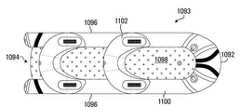
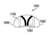
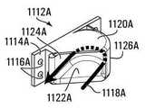
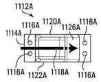
일부 실시예들에서, 차량의 벽에 정의된 홈 또는 흡입구들을 가지는 대신에, 차량의 본체로부터의 돌출부들이 있다. 도 10a 내지 도 10e의 실시예에, 그러한 차량(1093)의 본체의 평면도, 측면도, 저면도, 전면도, 및 후면도가 각각 도시된다. 이러한 실시예의 차량(1093)은 전면 단부(1092), 후면 단부(1094), 측면들(1096), 및 저면(1098)으로 이루어진 차량 본체를 가지는 변경된 뗏목 타입의 차량이다. 차량(1093)은 차량(1093) 주변의 부분적으로 연장되는 팽창된 튜브(1100)를 가지며 전면 단부(1092)와 측면들(1096)을 정의한다. 후면 단부(1094)의 중앙은 개방되어 있다. 저면(1098)은 팽창된 튜브(30)(도 10e 참조)의 하부 표면에 연결되어 승객들을 운반하기 위한 차량(1093)의 내부를 정의한다. 이러한 실시예에서, 차량(1093)은 또한 차량(1093)이 두 명의 탑승자를 수용할 수 있게 하는 두 개의 등 받침(1102)을 포함한다. 이러한 실시예에서, 등 받침(1102)들의 후방부는 등 받침(1102)의 후방부의 하부를 충격하는 물의 방향을 전환하여 탑승자로부터 멀어지게 하는 디플렉터(deflector)로서의 역할을 하도록 각을 이룬다. 일부 실시예들에서, 디플렉트가 별도로 제공되며, 디플렉터는 차량의 후면과 접촉하는 물의 방향을 하향으로 전환하여 차량으로부터 멀어지도록 보트의 후방부를 돌출시킨다.In some embodiments, instead of having grooves or inlets defined in the wall of the vehicle, there are protrusions from the body of the vehicle. 10A to 10E, a top view, a side view, a bottom view, a front view, and a rear view, respectively, of the body of such a
이러한 실시예에서, 전술한 바와 같이, 저면(1098)에 연결된 팽창된 튜브(1100)에 의해 측면들(1096)이 정의된다. 도 10b 내지 도 10e에 가장 잘 도시된 바와 같이, 튜브(1100)의 하부 표면(1104)은 차량(1093)의 저면(1098)의 하부 표면(1106) 위에 있으며, 차량(1093)의 두 개의 측면들(1096)의 외부 표면들(1108)은 저면(1098)의 외부 표면들(1110) 너머의 바깥쪽에 있다. 이는 돌출부들(1112)이 위치할 수 있는 두 개의 측면으로 이루어진 영역을 정의한다. 복수의 돌출부들(1112)은 차량의 반대편 측면들(96)을 따라 이격될 수 있으며 분사원들로부터 분사된 물이 차량(1093)에 힘을 제공하도록 충격할 수 있는 충격 표면을 제공하도록 각을 이룬다. 이러한 실시예에서, 돌출부들(1112)은 팽창된 튜브(1110) 아래에 있으며 하부(1098)에 인접해 있으나 측면들(1096) 또는 차량의 하부 측면(1104) 밑면 아래의 외부 측벽들을 넘어 외부로 연장되지는 않는다. 돌출부들은 평평하거나, 오목하거나, 볼록하거나, 또는 불규칙적인 충격 표면일 수 있다. 돌출부들은 분사원들로부터의 분사 방향에 수직이 되도록 각을 이룰 수 있거나, 작은 각을 이루거나, 큰 각을 이룰 수 있다. 돌출부들의 각도, 위치 및 모양은 서로 다를 수 있다.In this embodiment, as described above, the
일부 실시예들에서, 돌출부들은 차량(1093)과 일체로 형성될 수 있다. 다른 실시예들에서, 돌출부들(1112)은 차량(1093)에 부착될 수 있는 별도의 구성요소들일 수 있다. 일부 실시예들에서, 돌출부들은, 돌출부들의 수와 각도 양쪽 모두에 대하여, 제거될 수 있으며 재배치가 가능하다. 돌출부들은 또한 차량(1093)의 하부 표면 아래에 있을 수 있다.In some embodiments, the protrusions may be formed integrally with the
돌출부들은 도 10b 및 도 10e에 도시된 불규칙적인 모양 이외의 다른 모양일 수 있다. 돌출부들은 또한 차량(1093)의 외부 표면들(1108)을 넘어 또는 차량의 측면들(1096) 위로 또는 도 1 내지 8d에 관하여 논의된 그러한 돌출부들과 홈들의 임의의 조합에 의해 외부로 연장될 수 있다.The protrusions may have a shape other than the irregular shape shown in Figs. 10B and 10E. The protrusions may also extend outwardly beyond the
도 11a 내지 13c는 차량(1093)에 부착될 수 있는 돌출부들(1112A,1112B, 1112C)에 대한 3개의 다른 디자인들을 도시한다. 각각의 돌출부들(1112A,1112B, 1112C)은 정의된 개구부들(1116A,1116B,1116C)을 가지는 각각의 백 플레이트들(1114A, 1114B,1114C)을 가진다. 볼트와 같은 고정부재들을 사용하여 돌출부들(1112A,1112B,1112C)을 차량에 고정시키기 위해, 개구부들(1116A,1116B,1116C)이 이용될 수 있다. 돌출부들(1112A,1112B,1112C)은 백 플레이트들(1114A,1114B, 1114C)과 개구부들(1116A,1116B,1116C)을 가지지 않을 수 있으나 대신에 접착제와 같은 다른 수단들에 의해 고정될 수 있다. 복수의 돌출부는 또한, 각각의 백 플레이트에 대한 단일한 돌출 보다는, 단일한 백 플레이트에 형성될 수 있다.Figs. 11A-13C show three different designs for
돌출부들(1112A,1112B,1112C)은 다른 방향에서 돌출부들(1112A,1112B, 1112C)에 대하여 충격하는 물의 방향을 전환하기 위한 다른 모양들을 가진다. 화살표들(1118A,1118B,1118C)은 각각의 돌출부들(1112A,1112B,1112C)에 의해 물의 방향이 전환되는 방법을 나타낸다. 차량(1093)의 반대편에 대하여, 돌출부들(1112A, 1112B,1112C)의 거울 이미지들이 제공될 수 있다.The
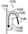
돌출부(1112A)는 평평하고 평행하게 이격된 상부(1120A)와 하부(1122A)를 가진다. 내부 벽(1124A)은 백 플레이트(1114A)의 측면으로 연장되며 상부(1120A)와 하부(1122A)를 연결한다. 내부 벽(1124A)은 백 플레이트(1114A)에 대하여 대략 15°의 각도를 이룬다. 단부 벽(1126A)은 상부(1120A)와 하부(1122A) 사이에서 연장되는 수직으로 배향된 관형 모양이다. 상부(1120A), 하부(1122A), 내부 벽(1124A)및 단부 벽(1126A)은 함께 외부를 향해 각을 이루는 직사각형 개구부를 가지는 취수구 또는 공동을 정의한다. 돌출부(1112A)의 공동 내에 분사된 워터젯은 화살표(1118A)에 의해 정의된 경로를 따른다. 특히, 물은 U자 모양의 수평 경로를 따라 이동한다. 단부 벽(1126A)은 충격 표면으로서 기능한다. 물은 수평으로 유입되어 단부 벽(1126A)을 충격하며 주변의 대략 단부 벽(1126A)의 곡률인 반원을 따르도록 방향이 전환된다. 돌출부(1112A)에 진입할 때, 물은 물의 경로에 평행한 오프셋 경로에서 내부 벽(1124A)을 따라 수평으로 배출된다.The
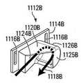
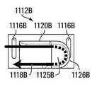
돌출부(1112B)는 개방된 하부 및 평행한 내부 및 외부 벽들(1124B,1125B)이 있는 평평한 상부(1120B)를 가진다. 내부 벽(1124B)은 백 플레이트(1114B)의 옆으로 연장되어 상부(1120B)에 연결되어 있다. 내부 벽(1124B)은 백 플레이트(1114B)에 대하여 대략 15°의 각도를 이룬다. 단부 벽(1126B)은 내부 벽(1124B)과 외부 벽(1125B) 사이에서 연장되는 수평으로 배향된 관형 모양을 가진다. 상부(1120B), 내부 벽(1124B), 외부 벽(1125B), 및 단부 벽(1126B)은 함께 외부로 각을 이루는 사각형 개구부 및 개방된 하부를 가지는 취수 공동을 정의한다. 돌출부(1112B)의 공동 안으로 분사된 워터 젯은 화살표(1118B)에 의해 정의된 경로를 따른다. 특히, 물은 U자 모양의 경로를 따라 이동한다. 단부 벽(1126B)은 충격 표면으로서 기능을 한다. 물은, 수평으로 유입되어, 단부 벽(1126B)을 충격하며, 단부 벽(1126B)의 곡률을 따르는 반원을 따르도록, 수직 하방의 U자 모양의 경로를 따라 방향이 전환된다. 돌출부(1112B)에 진입할 때, 물은 수직으로 아래이며 물의 경로에 평행한 오프셋 경로를 따라 배출된다.The
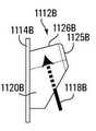
돌출부(1112C)는 쐐기 모양의 부분과 단부를 가진다. 단부는 평평하고 평행하게 이격된 상부(1120C)와 하부(1122C)를 가진다. 단부 벽(1126C)은 수직으로 배향되어 상부(1120C)와 하부(1122C) 사이로 연장되는 관형 모양으로 이루어진다. 단부 벽(1126C)의 내부 측면은 백 플레이트(1114C)에 연결된다. 상부(1120C), 하부(1122C), 및 단부 벽(1126C)은 취수 공동의 일부를 정의한다.The
쐐기 모양의 부분은, 백 플레이트(1114C) 옆으로 연장되고, 백 플레이트(1114C)와 평행한 삼각형 모양의 외부 벽(1125C)을 가지며, 백 플레이트(1114C)와 외부 벽(1125C)을 연결하는 하부로 각을 이루는 상부 플레이트(1121C)을 가진다. 쐐기 모양의 부분은 개방된 하부를 가지며 취수 공동의 제2 부분을 정의한다. 쐐기 모양의 부분의 사각형 단부는 단부의 내부 절반에 연결되어 취수 공동으로 개방된 수직의 직사각형 입구를 정의하고 취수 공동으로부터 개방된 직사각형의 수평적인 출구를 정의한다. 돌출부(1112C)의 공동 내에 분사된 워터젯은 화살표(1118C)에 의해 정의된 경로를 따른다. 단부 벽(1126C)은 충격 표면으로서 기능한다. 물은, 수평으로 유입되어, 단부 벽(1126C)을 충격하며, 대략 단부 벽(1126C)의 곡률인 반원을 따르도록 방향이 전환된다. 이후에, 쐐기 모양의 부분에 의해, 물의 방향이 하향 각도로 전환되며, 하향 각도로 방향이 전환된 물이 백 플레이트(1114C)를 따라 배출된다.The wedge-shaped portion has a triangular
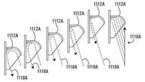
돌출부들(1112A,1112B,1112C)의 충격 표면에 대하여 분사된 물은 차량(1093)에 힘을 가하여 차량을 전방으로 추진시킨다. 도 14a, 도 14b, 및 도 14c는 차량(1093)이 전방으로 이동하여 물 분사원(1118A,1118B,1118C)에서 멀어짐에 따라 물 분사 경로(1118A,1118B,1118C)가 변경되는 방법을 도시한다.The water jetted against the impact surface of the
돌출부들(1112A,1112B,1112C)은 예시적인 돌출부들이다. 이러한 실시예에서, 돌출부들(1112A,1112B)은 2.5'' x 6'' x 3''의 치수인 높이 x 길이 x 폭을 가지며, 돌출부들(1112C)은 4''의 취수를 위해 2.5'' x 8'' x 4''의 치수인 높이 x 길이 x 폭을 가진다. 취수 공동이 있거나 또는 없든지, 물의 분사에 의해 적용된, 차량(1093)을 움직이게 하기 위한 힘을 얻기 위해 충격 표면을 정의하는 돌출부들 및 오목한 부분의 다양한 다른 모양들과 치수들이 형성될 수 있다는 것이 인정될 것이다. 돌출부들과 오목부들의 크기는 정해질 수 있으며, 제트 분사원과 결합하여, 차량에 바람직한 힘을 전달하기 위해 요구되는 수 만큼 제공될 수 있다.The
일부 실시예들에서, 분사원들에 의해 차량에 작용된 힘이, 예를 들어, 차량을 감속시키기 위해, 차량의 이동방향에 대항하여 작용하도록, 오목부들 및 돌출부들 및 분사원들은 반대방향으로 배향될 수 있다. 다른 실시예들에서, 예를 들어, 동일한 방향으로 둘레에 오목부를 가지는 원형의 차량은, 분사원들이 차량의 한쪽 측면에만 있을 수 있다. 분사원들에 의해 차랴엥 적용된 힘은 차량을 회전하게 할 수 있다. 일부 실시예들에서, 측면들을 따라 또는 반대편을 따르는 것과 같은, 차량의 다른 영역들에 균일하지 않은 힘이 작용되게 하기 위해, 오목부들 및 돌출부들은 비대칭일 수 있다.In some embodiments, the forces acting on the vehicle by the occupants act, for example, to decelerate the vehicle, against the direction of movement of the vehicle, such that the recesses and protrusions, . In other embodiments, for example, a circular vehicle having a concave portion in the circumferential direction in the same direction may be located on only one side of the vehicle. The power applied by the Chrysantians can cause the vehicle to turn. In some embodiments, the recesses and protrusions may be asymmetric in order to force non-uniform forces on other areas of the vehicle, such as along or along the sides.
차량(208)과 차량(508)은, 예를 들어, 도 1 내지 도 4c 및 도 10a 내지 14c에 서술된 바와 같은 차량 타입일 수 있다. 그러나, 다른 차량들이 사용될 수 있다는 것과, 도 1 내지 8d와 관련되어 서술된 제어 시스템이, 차량 또는 놀이 기구 구조의 요구에 따라, 다양한 타입의 차량들과 함께, 또는 차량들 없이 사용될 수 있다는 것이 인정될 것이다.
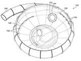
다른 실시예에서, 본 발명은, 미국 특허 번호 6,857,964에 서술된 바와 같은 깔때기 놀이기구 및 미국 디자인 특허 번호 D521,098에 서술된 바와 같은 접시 스타일의 놀이기구와 같은, 놀이공원 탑승기구의 다른 타입들과 관련되어 이용되며, 상기 특허들은 그 전체가 본 명세서에 참조로써 포함된다. 도 15는 그러한 접시 스타일의 라이드 피쳐(1150)에서 슬라이딩하는 원형의 차량(1152)를 도시한다. 차량(1152)은 차량의 주변에 복수의 취수 돌출부들(1154)을 가진다. 복수의 워터젯 분사원들(1158)은, 라이드 피쳐(1150)의 표면 또는 라이드 피쳐(1150) 표면의 아래에 실장될 수 있는 물 유입 파이프(1156)를 통하여, 라이드 피쳐(1150)의 표면을 통해 돌출되는 워터젯 분사원들(1158)과 연결되어 있다. 라이드 피쳐(1150)는 원형의 차량(1152)이 라이드 피쳐(1150)로 진입하는 유입구(1160)를 가진다. 분사원들(1158)로부터 분사된 워터젯은, 워터젯 및 돌출부 및/또는 오목부의 상대적인 배향에 따라, 취수 돌출부들(1154)에 대하여 충격하여 회전력을 전달하거나, 속력을 늦추거나, 속력을 높이거나, 또는 그렇지 않으면 차량(1152)의 움직임에 영향을 주기 위한 또다른 힘을 전달할 수 있다는 것이 인정될 것이다.In another embodiment, the present invention may be applied to other types of amusement park rides, such as funnel rides as described in U.S. Patent No. 6,857,964 and dish rides as described in U.S. Design Patent No. D521,098 , Which patents are incorporated herein by reference in their entirety. Fig. 15 shows a
일부 실시예들에서, 유체 충격 표면들은 채널 내 물의 표면 아래에 있으며, 유체 충격 표면을 충격하기 위해, 워터젯은 채널 내 물을 통하여 물줄기를 뿜어낸다.In some embodiments, the fluid impact surfaces are below the surface of the water in the channel, and the water jet sprays water through the water in the channel to impact the fluid impact surface.
전술한 교시의 관점에서, 본 발명의 다양한 변형이 가능하다. 따라서, 본 명세서에 서술된 것 보다는, 첨부된 청구범위 내에서, 본 발명은 실시될 수 있다는 것이 이해되어야 한다.Various modifications of the present invention are possible in light of the above teachings. It is, therefore, to be understood that within the scope of the appended claims, the invention may be practiced otherwise than as described herein.
Claims (42)
Translated fromKorean적어도 하나의 펌프;
적어도 하나의 유체 피쳐(fluid feature);
상기 유체 공급원 및 상기 적어도 하나의 펌프를 상기 적어도 하나의 유체 피쳐에 연결하는 복수의 도관들; 및
제어기를 포함하고,
상기 적어도 하나의 펌프는 상기 도관들을 통하여 상기 적어도 하나의 유체 피쳐에 유체를 퍼올리도록 구성되며,
유체를 각각의 유체 피쳐에 전달하기 위해, 상기 제어기는 상기 적어도 하나의 펌프를 제어하도록 조정되는 것을 특징으로 하는, 놀이공원 유체 제어 시스템.A fluid source;
At least one pump;
At least one fluid feature;
A plurality of conduits connecting the fluid source and the at least one pump to the at least one fluid feature; And
A controller,
Wherein the at least one pump is configured to pump fluid through the conduits to the at least one fluid feature,
And wherein the controller is adapted to control the at least one pump to deliver fluid to each of the fluid features.
상기 제어기로부터 수신된 입력에 기초하여 적어도 하나의 펌프 각각을 제어하기 위한 상기 적어도 하나의 펌프를 더 포함하는 것을 특징으로 하는, 놀이공원 유체 제어 시스템.2. The apparatus of claim 1, further comprising at least one variable frequency drive intermediate controller,
Further comprising: the at least one pump for controlling each of the at least one pump based on an input received from the controller.
적어도 하나의 펌프는 복수의 펌프들을 포함하며,
상기 복수의 유체 피쳐들 각각은 상기 복수의 펌프들에 관련된 적어도 하나의 펌프를 가지는 것을 특징으로 하는, 놀이공원 유체 제어 시스템.The method of claim 1, wherein the at least one fluid feature comprises a plurality of fluid features,
The at least one pump includes a plurality of pumps,
Wherein each of the plurality of fluid features has at least one pump associated with the plurality of pumps.
상기 참가자가 상기 유체 피쳐로부터 멀리 있을 때, 상기 적어도 하나의 펌프 각각은 상기 관련된 유체 피쳐로부터 유체 흐름률을 감소시키도록 조정되는 것을 특징으로 하는, 놀이공원 유체 제어 시스템.9. The method of claim 8, wherein when the participant is adjacent to the fluid feature, each of the at least one pump is adjusted to increase the fluid flow rate from the associated fluid feature,
Wherein the at least one pump is adjusted to reduce the fluid flow rate from the associated fluid feature when the participant is away from the fluid feature.
참가자가 각각의 워터 피쳐를 향하여 슬라이딩함에 따라, 적어도 하나의 펌프 각각은 각각의 상기 워터 피쳐로 흐르는 물의 흐름을 증가시키도록 조정되며,
상기 참가자가 상기 워터 피쳐로부터 슬라이딩하여 멀어짐에 따라, 상기 적어도 하나의 펌프 각각은 각각의 상기 워터 피쳐로 흐르는 물의 흐름을 감소시키도록 조정되는 것을 특징으로 하는, 제1항 내지 제10항 중 어느 한 항에 따른 놀이공원 물 제어 시스템을 포함하는, 워터슬라이드 영역.Each fluid feature is a water feature,
As the participant slides toward each water feature, each of the at least one pump is adjusted to increase the flow of water to each of the water features,
The method of any one of claims 1 to 10, characterized in that as the participant slides away from the water feature, each of the at least one pump is adjusted to reduce the flow of water to each of the water features A water slide area, comprising an amusement park water control system according to any of the preceding claims.
상기 복수의 유체 피쳐들은 상기 워터 슬라이드에 관련된 것을 특징으로 하는, 놀이공원.A playground park fluid control system according to any one of claims 1 to 12 and a water slide,
Wherein the plurality of fluid features are associated with the water slide.
상기 복수의 유체 특성들은 상기 물놀이 구조를 포함하는 것을 특징으로 하는, 놀이공원.12. A playground park fluid control system and a water play structure according to any one of claims 1 to 12,
Characterized in that the plurality of fluid properties comprise the dip structure.
펌프;
복수의 워터 피쳐들(water features);
상기 물 공급원 및 상기 펌프를 상기 복수의 워터 피쳐들에 연결하는 복수의 도관들; 및
각각의 관련된 밸브들을 가지는 상기 복수의 워터 피쳐들 각각을 포함하고,
상기 펌프는 상기 도관들을 통하여 상기 워터 피쳐들에 물을 퍼올리도록 구성되며,
상기 각각의 관련된 밸브들은 각각의 워터 피쳐에 물을 운반하도록 열리게 조정되는 것을 특징으로 하는, 물놀이 공원 물 제어 시스템.A water source;
Pump;
A plurality of water features;
A plurality of conduits connecting the water source and the pump to the plurality of water features; And
Each of the plurality of water features having respective associated valves,
Wherein the pump is configured to pump water through the conduits to the water features,
Wherein each of said associated valves is openly adjusted to carry water to each water feature.
상기 관련된 밸브들 중 적어도 하나는 상기 적어도 하나의 센서로부터의 입력에 기초하여 개방 위치와 폐쇄 위치 사이에서 이동할 수 있는 것을 특징으로 하는, 물놀이 공원 물 제어 시스템.16. The apparatus of claim 15, further comprising at least one sensor,
Wherein at least one of the associated valves is movable between an open position and a closed position based on an input from the at least one sensor.
각각의 관련된 밸브는 각각의 관련된 센서를 포함하는 것을 특징으로 하는, 물놀이 공원 물 제어 시스템.16. The method of claim 15, wherein the at least one sensor comprises a plurality of sensors,
RTI ID = 0.0 > 1, < / RTI > wherein each associated valve comprises a respective associated sensor.
상기 채널을 통하여 유체를 분사하도록 위치한 복수의 유체 분사원들;
놀이기구 차량이 상기 채널의 구역에 들어올 때, 상기 차량을 검출하도록 조정된 적어도 하나의 제1 센서;
상기 복수의 유체 분사원들과 관련된 적어도 하나의 펌프; 및
놀이기구 차량이 상기 구역에 진입하는 것에 응답하여, 상기 적어도 하나의 펌프에 의해 상기 유체 분사원들 각각으로 흐르는 유체 흐름을 증가시키도록 조정된 제어기를 포함하는 것을 특징으로 하는, 놀이기구 차량 운동 제어 시스템.channel;
A plurality of fluid distributors positioned to inject fluid through the channels;
At least one first sensor adapted to detect the vehicle when the rides vehicle enters the zone of the channel;
At least one pump associated with the plurality of fluid impedances; And
Characterized in that it comprises a controller adapted to increase the flow of fluid to each of the fluid power distributors by the at least one pump in response to the rider vehicle entering the zone, system.
상기 놀이기구 차량이 상기 구역을 벗어난 것에 응답하여 상기 유체 분사원으로부터의 흐름을 감소시키기 위해, 상기 제어기는 배출되는 유체를 감소시키도록 조정되는 것을 특징으로 하는, 놀이기구 차량 운동 제어 시스템.19. The apparatus of claim 18, further comprising at least one second sensor adapted to detect when the vehicle leaves the zone of the channel when the vehicle leaves the zone of the channel,
Characterized in that the controller is adapted to reduce the fluid to be discharged in order to reduce the flow from the fluid power distributor in response to the rider vehicle exiting the zone.
채널을 통해 유체를 분사하도록 위치한 복수의 제2 유체 분사원들;
상기 놀이기구 차량이 상기 채널의 제2 구역에 진입할 때, 차량을 검출하도록 조정된 적어도 하나의 제3 센서;
상기 복수의 제2 유체 분사원들과 관련된 적어도 하나의 제2 펌프; 및
상기 놀이기구 차량이 상기 구역에 진입하는 것에 응답하여, 적어도 하나의 제2 펌프에 의해 상기 복수의 제2 유체 분사원들 각각의 유체 흐름을 증가시키도록 조정된 제어기를 더 포함하는 것을 특징으로 하는, 놀이기구 차량 운동 제어 시스템.20. The method of claim 19,
A plurality of second fluid powders positioned to inject fluid through the channel;
At least one third sensor adapted to detect a vehicle when the rider vehicle enters a second zone of the channel;
At least one second pump associated with the plurality of second fluid impedances; And
Further comprising a controller adapted to increase the fluid flow of each of the plurality of second fluid parameters by at least one second pump in response to the rider vehicle entering the zone , Rides vehicle movement control system.
상기 가변 주파수 구동기는 상기 각각의 펌프의 작동율을 제어하도록 조정되는 것을 것을 특징으로 하는, 놀이기구 차량 운동 제어 시스템.21. The pump according to any one of claims 18 to 20, wherein each pump is connected to the controller by a variable frequency driver,
Wherein the variable frequency driver is adjusted to control an operating rate of each of the pumps.
상기 채널 내 차량에 물을 분사하기 위해 복수의 물 분사원들이 위치하는 단계;
차량이 상기 채널에 들어왔을 때 상기 차량을 감지하는 단계;
상기 차량의 운동에 영향을 주는 압력 및 흐름률로 상기 물 분사원으로부터 물을 분사하기 위해, 펌프율이 증가하는 단계를 포함하는 것을 특징으로 하는, 워터슬라이드 상에서 슬라이딩하는 차량의 운동에 영향을 주기 위한 방법.Providing a channel within the water slide;
A plurality of water jets are positioned to inject water into the in-channel vehicle;
Sensing the vehicle when the vehicle is in the channel;
Characterized in that the pump rate is increased in order to inject water from the water distribution element at a pressure and flow rate affecting the movement of the vehicle. Way.
상기 물 분사원으로부터 분사되는 물의 양을 감소시키기 위해, 펌프율이 감소하는 단계를 더 포함하는 것을 특징으로 하는, 차량의 운동에 영향을 주기 위한 방법.27. The method of claim 26, further comprising: sensing the vehicle when the vehicle is exiting the channel; And
Further comprising the step of reducing the pump rate to reduce the amount of water sprayed from the water distribution element.
상기 적어도 하나의 오목부들과 돌출부들은 유체 충격 표면들을 정의하며,
상기 유체 충격 표면들이 유체에 의해 충격될 때, 상기 유체 충격 표면들은, 차량의 운동에 영향을 주도록, 상기 차량을 움직이기 위한 방향으로 각을 이루는 것을 특징으로 하는, 놀이기구 차량.And at least one recess and protrusions around the surface of the body,
The at least one recess and protrusions define fluid impact surfaces,
Characterized in that when the fluid impact surfaces are impacted by the fluid, the fluid impact surfaces are angled in a direction for moving the vehicle so as to influence the movement of the vehicle.
상기 복수의 오목부들 및 복수의 돌출부들은, 상기 측벽들을 지나서 또는 상기 차량 본체의 하부 표면 아래를 지나서 연장되지 않거나, 상기 차량의 상부 표면 위로 연장되지 않는 것을 특징으로 하는, 놀이기구 차량.35. The apparatus of claim 34, wherein the vehicle includes outer sidewalls, and a lower surface, and a plurality of recesses or protrusions,
Wherein the plurality of recesses and the plurality of protrusions do not extend past the sidewalls or beneath the lower surface of the vehicle body or extend over the upper surface of the vehicle.
상기 복수의 오목부들 또는 복수의 돌출부들은 상기 측면들 아래에 위치하고 상기 본체의 하부에 인접하여 위치하는 것을 특징으로 하는, 놀이기구 차량.36. The vehicle of claim 35, wherein the vehicle includes sides, and a bottom, and a plurality of recesses or a plurality of protrusions,
Wherein the plurality of recesses or the plurality of protrusions are located below the side surfaces and adjacent to a lower portion of the main body.
Applications Claiming Priority (3)
| Application Number | Priority Date | Filing Date | Title |
|---|---|---|---|
| US201461983251P | 2014-04-23 | 2014-04-23 | |
| US61/983,251 | 2014-04-23 | ||
| PCT/CA2015/050339WO2015161382A1 (en) | 2014-04-23 | 2015-04-23 | Amusement attraction fluid control system |
Publications (1)
| Publication Number | Publication Date |
|---|---|
| KR20160147908Atrue KR20160147908A (en) | 2016-12-23 |
Family
ID=54331537
Family Applications (1)
| Application Number | Title | Priority Date | Filing Date |
|---|---|---|---|
| KR1020167032794AAbandonedKR20160147908A (en) | 2014-04-23 | 2015-04-23 | Amusement attraction fluid control system |
Country Status (11)
| Country | Link |
|---|---|
| US (1) | US11090571B2 (en) |
| EP (1) | EP3134191B1 (en) |
| KR (1) | KR20160147908A (en) |
| CN (1) | CN106659939B (en) |
| AU (2) | AU2015251474A1 (en) |
| BR (1) | BR112016024294A2 (en) |
| CA (1) | CA2946045C (en) |
| ES (1) | ES2751644T3 (en) |
| RU (1) | RU2687762C2 (en) |
| SG (1) | SG11201608816SA (en) |
| WO (1) | WO2015161382A1 (en) |
Families Citing this family (17)
| Publication number | Priority date | Publication date | Assignee | Title |
|---|---|---|---|---|
| TR201908712T4 (en) | 2012-10-19 | 2019-07-22 | Proslide Technology Inc | Entertainment purpose vehicle and vehicle control system. |
| KR20160147908A (en) | 2014-04-23 | 2016-12-23 | 프로슬라이드 테크놀로지 인코포레이티드 | Amusement attraction fluid control system |
| RU2019108618A (en) | 2014-06-13 | 2019-04-29 | Прослайд Текнолоджи Инк. | WATER ATTRACTION |
| US10717014B2 (en) | 2016-07-11 | 2020-07-21 | Polin Su Parklari Ve Havuz Sistemleri Anonim Sirketi | Bowl-type waterslide assembly |
| USD846479S1 (en) | 2016-07-15 | 2019-04-23 | Proslide Technology Inc. | Water ride vehicle |
| USD813337S1 (en) | 2016-07-15 | 2018-03-20 | Proslide Technology Inc. | Water ride |
| AU2016414688B2 (en) | 2016-07-15 | 2022-05-12 | Proslide Technology Inc. | Waterslide feature, ride vehicle and method |
| USD870015S1 (en) | 2016-07-15 | 2019-12-17 | Proslide Technology Inc. | Water ride vehicle intake |
| WO2018080409A1 (en)* | 2016-10-25 | 2018-05-03 | Polin Su Parklari Ve Havuz Sistemleri Anonim Sirketi | A bowl-type water slide |
| CA3043257A1 (en)* | 2016-11-11 | 2018-05-17 | Proslide Technology Inc. | System and method for affecting motion of an amusement ride vehicle |
| US11273383B2 (en)* | 2017-11-10 | 2022-03-15 | Whitewater West Industries Ltd. | Water ride attraction incorporating a standing wave |
| CN108014502A (en)* | 2017-12-26 | 2018-05-11 | 深圳市维骏文化旅游科技有限公司 | Current shunting method and device |
| US10698426B2 (en)* | 2018-05-07 | 2020-06-30 | Mks Instruments, Inc. | Methods and apparatus for multiple channel mass flow and ratio control systems |
| CA3097785C (en) | 2018-05-18 | 2023-08-29 | Proslide Technology Inc. | Spray nozzle for water slide feature |
| CN110227270B (en)* | 2019-06-13 | 2020-10-09 | 福建省特种设备检验研究院 | A monitoring, management and control system for safe operation of a spiral water slide |
| DE102021107560A1 (en)* | 2021-03-25 | 2022-09-29 | Aquarena Holding Gmbh | Method for controlling a sliding direction in a switch and switch for a slide, in particular a water slide |
| DE102021107558A1 (en) | 2021-03-25 | 2022-09-29 | Aquarena Holding Gmbh | Slide, especially water slide |
Family Cites Families (57)
| Publication number | Priority date | Publication date | Assignee | Title |
|---|---|---|---|---|
| US2604055A (en) | 1949-07-13 | 1952-07-22 | Charles E Snowden | Aquatic toy |
| US3000022A (en) | 1959-07-10 | 1961-09-19 | Carrol M Cathey | Spherical amusement device |
| US3438074A (en) | 1968-02-07 | 1969-04-15 | Garrett E Goyen | Portable watercraft |
| NZ222572A (en) | 1986-11-18 | 1990-03-27 | Leonard Jefferson Blee | Marine hull; recess in hull bottom vented to atmosphere |
| GB8702588D0 (en) | 1987-02-05 | 1987-03-11 | Sar Plc | Watercraft |
| US5738590A (en) | 1987-05-27 | 1998-04-14 | Lochtefeld; Thomas J. | Method and apparatus for a sheet flow water ride in a single container |
| JPH03258280A (en) | 1990-03-07 | 1991-11-18 | Nkk Corp | Game equipment utilizing water |
| US5230662A (en) | 1990-03-26 | 1993-07-27 | Frederick Langford | Waterslide with uphill run and flotation device therefor |
| US5213547A (en)* | 1990-08-15 | 1993-05-25 | Light Wave, Ltd. | Method and apparatus for improved water rides by water injection and flume design |
| WO1992004087A1 (en) | 1990-09-04 | 1992-03-19 | Lochtefeld Thomas J | Water ride attraction |
| US5219315A (en) | 1991-06-28 | 1993-06-15 | Mark Fuller | Water effects enhanced motion base simulator ride |
| NL9202110A (en) | 1992-12-07 | 1994-07-01 | Lotec Bv | Water slide device and method for operating a water slide device. |
| EP0617329B1 (en) | 1993-03-25 | 2001-10-31 | Sumitomo Electric Industries, Limited | Method of forming a micro structure and an X-ray mask |
| US5503597A (en)* | 1994-03-09 | 1996-04-02 | Lochtefeld; Thomas J. | Method and apparatus for injected water corridor attractions |
| US5716282A (en) | 1996-07-08 | 1998-02-10 | Bay Boats, Inc. | Spinning water ride apparatus and method |
| JPH10216363A (en) | 1997-02-04 | 1998-08-18 | Mitsui Eng & Shipbuild Co Ltd | Water flow generator for game boat movement |
| US6006672A (en) | 1998-02-03 | 1999-12-28 | O.D. Hopkins Associates, Incorporated | Boat reversing waterway |
| US6758231B1 (en) | 1998-06-17 | 2004-07-06 | Light Wave Ltd. | Redundant array control system for water rides |
| US6261186B1 (en) | 1998-07-24 | 2001-07-17 | Nbgs International, Inc. | Water amusement system and method |
| US6527646B1 (en)* | 2000-01-27 | 2003-03-04 | Rick A. Briggs | Competition water slide |
| US6702687B1 (en) | 2000-06-23 | 2004-03-09 | Nbgs International, Inc. | Controller system for water amusement devices |
| CA2422023C (en) | 2000-09-11 | 2009-05-12 | Jeffery Wayne Henry | Water amusement system and method |
| US6743108B2 (en) | 2000-12-12 | 2004-06-01 | Proslide Technology Inc. | Random path flume ride |
| US6435927B1 (en) | 2001-03-05 | 2002-08-20 | Riva Sports, Inc. | Recreational floating device having underwater projectile dispensing feature |
| US20030069078A1 (en) | 2001-10-09 | 2003-04-10 | Wizard Works, Inc. | Time-configurable water park amusement ride |
| US7731595B2 (en) | 2001-11-16 | 2010-06-08 | White Water West Industries, Ltd. | Waterslide amusement device |
| US7025791B2 (en) | 2002-12-02 | 2006-04-11 | Gi Dynamics, Inc. | Bariatric sleeve |
| US7229359B2 (en) | 2003-10-24 | 2007-06-12 | Henry, Schooley & Associates, L.L.C. | Continuous water ride |
| US7497784B2 (en) | 2004-11-24 | 2009-03-03 | Water Ride Concepts, Inc. | Rollable carrier ride |
| US7597630B2 (en) | 2004-11-24 | 2009-10-06 | Water Ride Concepts, Inc. | Water amusement park conveyors |
| KR20080017316A (en) | 2005-04-20 | 2008-02-26 | 헨리, 스쿨리 앤 어소시에이트 엘엘씨 | Water Riding System with Synthetic Wood |
| US7727077B2 (en) | 2005-08-03 | 2010-06-01 | Water Ride Concepts, Inc. | Water amusement park water channel flow system |
| US8282497B2 (en) | 2005-08-30 | 2012-10-09 | Water Ride Concepts, Inc. | Modular water amusement park conveyors |
| US7371183B2 (en) | 2005-08-30 | 2008-05-13 | Henry, Schooley & Associates, L.L.C. | Water amusement park conveyors |
| WO2007027841A2 (en) | 2005-08-30 | 2007-03-08 | Water Ride Concepts Inc. | Water amusement park conveyors |
| US7828667B2 (en)* | 2005-09-02 | 2010-11-09 | Water Ride Concepts, Inc. | Methods and systems for active filtration of portions of self-contained floating marine parks |
| US8210954B2 (en) | 2005-09-02 | 2012-07-03 | Water Ride Concepts, Inc. | Amusement water rides involving exercise circuits |
| US7758435B2 (en) | 2005-09-02 | 2010-07-20 | Water Ride Concepts, Inc. | Amusement water rides involving interactive user environments |
| US7762900B2 (en) | 2006-03-14 | 2010-07-27 | Water Ride Concepts, Inc. | Method and system of positionable covers for water amusement parks |
| CN2905159Y (en)* | 2006-04-17 | 2007-05-30 | 易学愚 | Water roller coaster |
| RU68338U1 (en)* | 2007-07-06 | 2007-11-27 | Вадим Дмитриевич Орлов | PNEUMATIC WATER PARK |
| US7896752B2 (en) | 2007-11-07 | 2011-03-01 | Lance Yule | Amusement ride system |
| CN101417179B (en) | 2007-11-14 | 2011-12-21 | 陆健 | High-position driftage water canal |
| CA2671757C (en) | 2008-07-15 | 2014-07-08 | Whitewater West Industries Ltd. | Twisted waterslide flume |
| GB0818483D0 (en) | 2008-10-08 | 2008-11-12 | Cuttell David J | Water or leisure slide |
| US8079916B2 (en) | 2008-12-18 | 2011-12-20 | Water Ride Concepts, Inc. | Themed amusement river ride system |
| US8070616B2 (en) | 2009-07-31 | 2011-12-06 | Raymond Joseph Dubois | Method and apparatus for adjusting rider movement on a waterslide amusement device |
| CA2674329C (en) | 2009-07-31 | 2013-10-08 | Whitewater West Industries Ltd. | Method and apparatus for adjusting rider movement on a waterslide amusement device |
| HRP20161779T1 (en) | 2010-03-23 | 2017-02-24 | Polin Su Parklari Ve Havuz Sistemleri Anonim Sirketi | WATERBOARD WITH MULTIPLE TRAILS AND COMMON SLEEPING |
| CA2813746A1 (en) | 2010-10-05 | 2012-04-12 | Splashtacular, Inc. | Amusement slide elements and systems |
| US9457290B2 (en) | 2011-02-04 | 2016-10-04 | Kenneth Douglas Hill | Wave simulator for board sports |
| US8684855B2 (en) | 2011-04-08 | 2014-04-01 | Universal City Studios Llc | Articulated waterslide |
| US8453579B2 (en) | 2011-05-20 | 2013-06-04 | Disney Enterprises, Inc. | Water ride with improved boat capture mechanism |
| CN103813838B (en) | 2011-06-30 | 2017-02-15 | 哈姆游乐设施股份有限公司 | Motion control system and method for an amusement ride |
| TR201908712T4 (en) | 2012-10-19 | 2019-07-22 | Proslide Technology Inc | Entertainment purpose vehicle and vehicle control system. |
| US9220989B2 (en) | 2012-12-13 | 2015-12-29 | Skyturtle Technologies Ltd. | Water jet ride |
| KR20160147908A (en) | 2014-04-23 | 2016-12-23 | 프로슬라이드 테크놀로지 인코포레이티드 | Amusement attraction fluid control system |
- 2015
- 2015-04-23KRKR1020167032794Apatent/KR20160147908A/ennot_activeAbandoned
- 2015-04-23RURU2016145423Apatent/RU2687762C2/ennot_activeIP Right Cessation
- 2015-04-23EPEP15783231.2Apatent/EP3134191B1/enactiveActive
- 2015-04-23BRBR112016024294Apatent/BR112016024294A2/ennot_activeApplication Discontinuation
- 2015-04-23USUS15/305,859patent/US11090571B2/enactiveActive
- 2015-04-23SGSG11201608816SApatent/SG11201608816SA/enunknown
- 2015-04-23ESES15783231Tpatent/ES2751644T3/enactiveActive
- 2015-04-23WOPCT/CA2015/050339patent/WO2015161382A1/enactiveApplication Filing
- 2015-04-23CNCN201580031828.6Apatent/CN106659939B/enactiveActive
- 2015-04-23AUAU2015251474Apatent/AU2015251474A1/ennot_activeAbandoned
- 2015-04-23CACA2946045Apatent/CA2946045C/enactiveActive
- 2021
- 2021-01-13AUAU2021200166Apatent/AU2021200166A1/ennot_activeAbandoned
Also Published As
| Publication number | Publication date |
|---|---|
| EP3134191A4 (en) | 2017-11-29 |
| AU2015251474A1 (en) | 2016-11-03 |
| CN106659939A (en) | 2017-05-10 |
| US11090571B2 (en) | 2021-08-17 |
| AU2021200166A1 (en) | 2021-03-18 |
| RU2016145423A (en) | 2018-05-24 |
| CA2946045A1 (en) | 2015-10-29 |
| CA2946045C (en) | 2022-08-23 |
| CN106659939B (en) | 2020-02-18 |
| RU2687762C2 (en) | 2019-05-16 |
| EP3134191B1 (en) | 2019-07-03 |
| SG11201608816SA (en) | 2016-11-29 |
| US20170043264A1 (en) | 2017-02-16 |
| BR112016024294A2 (en) | 2017-08-15 |
| ES2751644T3 (en) | 2020-04-01 |
| EP3134191A1 (en) | 2017-03-01 |
| WO2015161382A1 (en) | 2015-10-29 |
Similar Documents
| Publication | Publication Date | Title |
|---|---|---|
| KR20160147908A (en) | Amusement attraction fluid control system | |
| US11077378B2 (en) | Amusement ride vehicle and vehicle control system | |
| US11141666B2 (en) | Looping saucer amusement attraction and method for making the same | |
| AU2001290832A1 (en) | Water amusement system and method | |
| CA2089580C (en) | Water ride with water propulsion devices | |
| JP2021500175A (en) | Amusement vehicle | |
| US9623339B2 (en) | Water jet ride | |
| HK1237297A1 (en) | Amusement attraction fluid control system | |
| JP7365034B2 (en) | water slide | |
| HK40013146A (en) | Amusement ride vehicle and vehicle control system | |
| HK1231005B (en) | Amusement ride vehicle and vehicle control system | |
| HK1231005A1 (en) | Amusement ride vehicle and vehicle control system | |
| CN111202992A (en) | Turbine type hydraulic ejection device |
Legal Events
| Date | Code | Title | Description |
|---|---|---|---|
| PA0105 | International application | St.27 status event code:A-0-1-A10-A15-nap-PA0105 | |
| PG1501 | Laying open of application | St.27 status event code:A-1-1-Q10-Q12-nap-PG1501 | |
| A201 | Request for examination | ||
| P11-X000 | Amendment of application requested | St.27 status event code:A-2-2-P10-P11-nap-X000 | |
| P13-X000 | Application amended | St.27 status event code:A-2-2-P10-P13-nap-X000 | |
| PA0201 | Request for examination | St.27 status event code:A-1-2-D10-D11-exm-PA0201 | |
| D13-X000 | Search requested | St.27 status event code:A-1-2-D10-D13-srh-X000 | |
| D14-X000 | Search report completed | St.27 status event code:A-1-2-D10-D14-srh-X000 | |
| E902 | Notification of reason for refusal | ||
| PE0902 | Notice of grounds for rejection | St.27 status event code:A-1-2-D10-D21-exm-PE0902 | |
| T11-X000 | Administrative time limit extension requested | St.27 status event code:U-3-3-T10-T11-oth-X000 | |
| E13-X000 | Pre-grant limitation requested | St.27 status event code:A-2-3-E10-E13-lim-X000 | |
| P11-X000 | Amendment of application requested | St.27 status event code:A-2-2-P10-P11-nap-X000 | |
| P13-X000 | Application amended | St.27 status event code:A-2-2-P10-P13-nap-X000 | |
| E90F | Notification of reason for final refusal | ||
| PE0902 | Notice of grounds for rejection | St.27 status event code:A-1-2-D10-D21-exm-PE0902 | |
| P11-X000 | Amendment of application requested | St.27 status event code:A-2-2-P10-P11-nap-X000 | |
| P13-X000 | Application amended | St.27 status event code:A-2-2-P10-P13-nap-X000 | |
| E701 | Decision to grant or registration of patent right | ||
| PE0701 | Decision of registration | St.27 status event code:A-1-2-D10-D22-exm-PE0701 | |
| PC1904 | Unpaid initial registration fee | St.27 status event code:A-2-2-U10-U14-oth-PC1904 St.27 status event code:N-2-6-B10-B12-nap-PC1904 |