KR20160147636A - Head Mounted Display Apparatus - Google Patents
Head Mounted Display ApparatusDownload PDFInfo
- Publication number
- KR20160147636A KR20160147636AKR1020160006427AKR20160006427AKR20160147636AKR 20160147636 AKR20160147636 AKR 20160147636AKR 1020160006427 AKR1020160006427 AKR 1020160006427AKR 20160006427 AKR20160006427 AKR 20160006427AKR 20160147636 AKR20160147636 AKR 20160147636A
- Authority
- KR
- South Korea
- Prior art keywords
- user
- active element
- display
- visual acuity
- image
- Prior art date
- Legal status (The legal status is an assumption and is not a legal conclusion. Google has not performed a legal analysis and makes no representation as to the accuracy of the status listed.)
- Withdrawn
Links
Images


Classifications
- A—HUMAN NECESSITIES
- A61—MEDICAL OR VETERINARY SCIENCE; HYGIENE
- A61B—DIAGNOSIS; SURGERY; IDENTIFICATION
- A61B3/00—Apparatus for testing the eyes; Instruments for examining the eyes
- A61B3/10—Objective types, i.e. instruments for examining the eyes independent of the patients' perceptions or reactions
- A61B3/103—Objective types, i.e. instruments for examining the eyes independent of the patients' perceptions or reactions for determining refraction, e.g. refractometers, skiascopes
- A—HUMAN NECESSITIES
- A61—MEDICAL OR VETERINARY SCIENCE; HYGIENE
- A61B—DIAGNOSIS; SURGERY; IDENTIFICATION
- A61B3/00—Apparatus for testing the eyes; Instruments for examining the eyes
- A61B3/10—Objective types, i.e. instruments for examining the eyes independent of the patients' perceptions or reactions
- A61B3/1015—Objective types, i.e. instruments for examining the eyes independent of the patients' perceptions or reactions for wavefront analysis
- G—PHYSICS
- G02—OPTICS
- G02B—OPTICAL ELEMENTS, SYSTEMS OR APPARATUS
- G02B26/00—Optical devices or arrangements for the control of light using movable or deformable optical elements
- G02B26/08—Optical devices or arrangements for the control of light using movable or deformable optical elements for controlling the direction of light
- G02B26/0816—Optical devices or arrangements for the control of light using movable or deformable optical elements for controlling the direction of light by means of one or more reflecting elements
- G02B26/0825—Optical devices or arrangements for the control of light using movable or deformable optical elements for controlling the direction of light by means of one or more reflecting elements the reflecting element being a flexible sheet or membrane, e.g. for varying the focus
- G—PHYSICS
- G02—OPTICS
- G02B—OPTICAL ELEMENTS, SYSTEMS OR APPARATUS
- G02B26/00—Optical devices or arrangements for the control of light using movable or deformable optical elements
- G02B26/08—Optical devices or arrangements for the control of light using movable or deformable optical elements for controlling the direction of light
- G02B26/0816—Optical devices or arrangements for the control of light using movable or deformable optical elements for controlling the direction of light by means of one or more reflecting elements
- G02B26/0833—Optical devices or arrangements for the control of light using movable or deformable optical elements for controlling the direction of light by means of one or more reflecting elements the reflecting element being a micromechanical device, e.g. a MEMS mirror, DMD
- G—PHYSICS
- G02—OPTICS
- G02B—OPTICAL ELEMENTS, SYSTEMS OR APPARATUS
- G02B26/00—Optical devices or arrangements for the control of light using movable or deformable optical elements
- G02B26/08—Optical devices or arrangements for the control of light using movable or deformable optical elements for controlling the direction of light
- G02B26/10—Scanning systems
- G02B26/101—Scanning systems with both horizontal and vertical deflecting means, e.g. raster or XY scanners
- G—PHYSICS
- G02—OPTICS
- G02B—OPTICAL ELEMENTS, SYSTEMS OR APPARATUS
- G02B27/00—Optical systems or apparatus not provided for by any of the groups G02B1/00 - G02B26/00, G02B30/00
- G02B27/0093—Optical systems or apparatus not provided for by any of the groups G02B1/00 - G02B26/00, G02B30/00 with means for monitoring data relating to the user, e.g. head-tracking, eye-tracking
- G—PHYSICS
- G02—OPTICS
- G02B—OPTICAL ELEMENTS, SYSTEMS OR APPARATUS
- G02B27/00—Optical systems or apparatus not provided for by any of the groups G02B1/00 - G02B26/00, G02B30/00
- G02B27/01—Head-up displays
- G02B27/017—Head mounted
- G02B27/0172—Head mounted characterised by optical features
- G—PHYSICS
- G02—OPTICS
- G02B—OPTICAL ELEMENTS, SYSTEMS OR APPARATUS
- G02B27/00—Optical systems or apparatus not provided for by any of the groups G02B1/00 - G02B26/00, G02B30/00
- G02B27/10—Beam splitting or combining systems
- G02B27/1066—Beam splitting or combining systems for enhancing image performance, like resolution, pixel numbers, dual magnifications or dynamic range, by tiling, slicing or overlapping fields of view
- G02B27/26—
- G—PHYSICS
- G02—OPTICS
- G02B—OPTICAL ELEMENTS, SYSTEMS OR APPARATUS
- G02B27/00—Optical systems or apparatus not provided for by any of the groups G02B1/00 - G02B26/00, G02B30/00
- G02B27/28—Optical systems or apparatus not provided for by any of the groups G02B1/00 - G02B26/00, G02B30/00 for polarising
- G02B27/286—Optical systems or apparatus not provided for by any of the groups G02B1/00 - G02B26/00, G02B30/00 for polarising for controlling or changing the state of polarisation, e.g. transforming one polarisation state into another
- G—PHYSICS
- G06—COMPUTING OR CALCULATING; COUNTING
- G06T—IMAGE DATA PROCESSING OR GENERATION, IN GENERAL
- G06T19/00—Manipulating 3D models or images for computer graphics
- G06T19/006—Mixed reality
- G—PHYSICS
- G06—COMPUTING OR CALCULATING; COUNTING
- G06V—IMAGE OR VIDEO RECOGNITION OR UNDERSTANDING
- G06V40/00—Recognition of biometric, human-related or animal-related patterns in image or video data
- G06V40/10—Human or animal bodies, e.g. vehicle occupants or pedestrians; Body parts, e.g. hands
- G06V40/18—Eye characteristics, e.g. of the iris
- G06V40/19—Sensors therefor
- G—PHYSICS
- G06—COMPUTING OR CALCULATING; COUNTING
- G06V—IMAGE OR VIDEO RECOGNITION OR UNDERSTANDING
- G06V40/00—Recognition of biometric, human-related or animal-related patterns in image or video data
- G06V40/10—Human or animal bodies, e.g. vehicle occupants or pedestrians; Body parts, e.g. hands
- G06V40/18—Eye characteristics, e.g. of the iris
- G06V40/193—Preprocessing; Feature extraction
- G—PHYSICS
- G02—OPTICS
- G02B—OPTICAL ELEMENTS, SYSTEMS OR APPARATUS
- G02B27/00—Optical systems or apparatus not provided for by any of the groups G02B1/00 - G02B26/00, G02B30/00
- G02B27/01—Head-up displays
- G02B27/0101—Head-up displays characterised by optical features
- G02B2027/011—Head-up displays characterised by optical features comprising device for correcting geometrical aberrations, distortion
- G—PHYSICS
- G02—OPTICS
- G02B—OPTICAL ELEMENTS, SYSTEMS OR APPARATUS
- G02B27/00—Optical systems or apparatus not provided for by any of the groups G02B1/00 - G02B26/00, G02B30/00
- G02B27/01—Head-up displays
- G02B27/0101—Head-up displays characterised by optical features
- G02B2027/0123—Head-up displays characterised by optical features comprising devices increasing the field of view
- G—PHYSICS
- G02—OPTICS
- G02B—OPTICAL ELEMENTS, SYSTEMS OR APPARATUS
- G02B27/00—Optical systems or apparatus not provided for by any of the groups G02B1/00 - G02B26/00, G02B30/00
- G02B27/01—Head-up displays
- G02B27/0101—Head-up displays characterised by optical features
- G02B2027/0127—Head-up displays characterised by optical features comprising devices increasing the depth of field
- G—PHYSICS
- G02—OPTICS
- G02B—OPTICAL ELEMENTS, SYSTEMS OR APPARATUS
- G02B27/00—Optical systems or apparatus not provided for by any of the groups G02B1/00 - G02B26/00, G02B30/00
- G02B27/01—Head-up displays
- G02B27/0101—Head-up displays characterised by optical features
- G02B2027/0132—Head-up displays characterised by optical features comprising binocular systems
- G02B2027/0134—Head-up displays characterised by optical features comprising binocular systems of stereoscopic type
- G—PHYSICS
- G02—OPTICS
- G02B—OPTICAL ELEMENTS, SYSTEMS OR APPARATUS
- G02B27/00—Optical systems or apparatus not provided for by any of the groups G02B1/00 - G02B26/00, G02B30/00
- G02B27/01—Head-up displays
- G02B27/0101—Head-up displays characterised by optical features
- G02B2027/014—Head-up displays characterised by optical features comprising information/image processing systems
- G—PHYSICS
- G02—OPTICS
- G02B—OPTICAL ELEMENTS, SYSTEMS OR APPARATUS
- G02B27/00—Optical systems or apparatus not provided for by any of the groups G02B1/00 - G02B26/00, G02B30/00
- G02B27/01—Head-up displays
- G02B27/017—Head mounted
- G02B2027/0178—Eyeglass type
- G—PHYSICS
- G02—OPTICS
- G02B—OPTICAL ELEMENTS, SYSTEMS OR APPARATUS
- G02B27/00—Optical systems or apparatus not provided for by any of the groups G02B1/00 - G02B26/00, G02B30/00
- G02B27/01—Head-up displays
- G02B27/0179—Display position adjusting means not related to the information to be displayed
- G02B2027/0185—Displaying image at variable distance
- G02B2027/0189—
- G—PHYSICS
- G02—OPTICS
- G02B—OPTICAL ELEMENTS, SYSTEMS OR APPARATUS
- G02B27/00—Optical systems or apparatus not provided for by any of the groups G02B1/00 - G02B26/00, G02B30/00
- G02B27/30—Collimators
- G—PHYSICS
- G02—OPTICS
- G02B—OPTICAL ELEMENTS, SYSTEMS OR APPARATUS
- G02B5/00—Optical elements other than lenses
- G02B5/30—Polarising elements
- G—PHYSICS
- G02—OPTICS
- G02B—OPTICAL ELEMENTS, SYSTEMS OR APPARATUS
- G02B6/00—Light guides; Structural details of arrangements comprising light guides and other optical elements, e.g. couplings
- G02B6/0001—Light guides; Structural details of arrangements comprising light guides and other optical elements, e.g. couplings specially adapted for lighting devices or systems
- G02B6/0011—Light guides; Structural details of arrangements comprising light guides and other optical elements, e.g. couplings specially adapted for lighting devices or systems the light guides being planar or of plate-like form
- G02B6/0033—Means for improving the coupling-out of light from the light guide
- G02B6/0056—Means for improving the coupling-out of light from the light guide for producing polarisation effects, e.g. by a surface with polarizing properties or by an additional polarizing elements
- G—PHYSICS
- G02—OPTICS
- G02B—OPTICAL ELEMENTS, SYSTEMS OR APPARATUS
- G02B6/00—Light guides; Structural details of arrangements comprising light guides and other optical elements, e.g. couplings
- G02B6/24—Coupling light guides
- G02B6/26—Optical coupling means
- G02B6/34—Optical coupling means utilising prism or grating
Landscapes
- Physics & Mathematics (AREA)
- Engineering & Computer Science (AREA)
- General Physics & Mathematics (AREA)
- Health & Medical Sciences (AREA)
- Life Sciences & Earth Sciences (AREA)
- Optics & Photonics (AREA)
- General Health & Medical Sciences (AREA)
- Ophthalmology & Optometry (AREA)
- Surgery (AREA)
- Heart & Thoracic Surgery (AREA)
- Medical Informatics (AREA)
- Molecular Biology (AREA)
- Biomedical Technology (AREA)
- Animal Behavior & Ethology (AREA)
- Biophysics (AREA)
- Public Health (AREA)
- Veterinary Medicine (AREA)
- Theoretical Computer Science (AREA)
- Human Computer Interaction (AREA)
- Multimedia (AREA)
- Computer Hardware Design (AREA)
- General Engineering & Computer Science (AREA)
- Software Systems (AREA)
- Computer Graphics (AREA)
- Computer Vision & Pattern Recognition (AREA)
Abstract
Description
Translated fromKorean본 발명은 헤드 마운티드 디스플레이 장치에 관한 것으로, 더욱 상세하게는 액티브 소자를 이용하여 사용자의 시력을 측정하고, 초점을 조절하여 시력을 보정하는 디스플레이 장치에 관한 것이다.The present invention relates to a head-mounted display device, and more particularly, to a display device for measuring a visual acuity of a user using an active element and correcting the visual acuity by adjusting the focus.
헤드 마운티드 디스플레이(HMD, Head Mounted Display)에서, 광학계(the optics)는 물체의 이미지(image source)를 시준(collimate)하고, 확대(magnify)하며, 릴레이(relay)하도록 한다. 이미지를 시준하는 것은 가상의 이미지를 생성하여 사용자의 안면으로부터 수 인치(a few inches)보다 더 멀리 나타나도록 하는 것이다. 이미지를 확대하는 것은 이미지의 실제 사이즈보다 더 크게 영상을 만드는 것이다. 이미지를 릴레이하는 것은 사용자의 안면 및 물체의 이미지로부터 가상의 이미지를 멀리(away from) 생성하는 것이다.In a head mounted display (HMD), the optics collimate, magnify, and relay an image of an object. Collimating the image is creating a virtual image so that it appears a few inches away from the user ' s face. Magnifying an image is making the image bigger than the actual size of the image. Relaying an image is creating a virtual image away from the user's face and the image of the object.
최근, 헤드 마운티드 디스플레이 (HMD)는 가상 현실(vitual reality)과 증강 현실(augmented reality)을 디스플레이함으로써, 더 정교하고 세밀한 기술을 요구하게 된다. 특히, 헤드 마운티드 디스플레이 (HMD)는 사용자의 눈과 초근접한 디스플레이 장치이므로 사용자의 눈의 피로를 감소할 수 있는 기술이 요구되고 있다.In recent years, head-mounted displays (HMDs) have demanded more sophisticated and detailed techniques by displaying virtual reality and augmented reality. In particular, since the head-mounted display (HMD) is a display device close to the user's eyes, there is a demand for a technique capable of reducing fatigue of the user's eyes.
종래에는 헤드 마운티드 디스플레이 (HMD)를 이용하는 사용자의 시력을 측정하고 보정하는 기술로서, 헤드 마운티드 디스플레이 (HMD) 내의 광학계를 구성하는 렌즈의 위치를 조절하여 광로 길이를 제어하여 시력을 보정하는 방법이 있다. 또한, 시력을 보정하는 방법으로, 헤드 마운티드 디스플레이 (HMD)의 광학계를 구성하는 디스플레이의 위치를 조절하여 광로 길이를 제어하는 방법도 있다.Conventionally, as a technique for measuring and correcting the visual acuity of a user using a head-mounted display (HMD), there is a method of correcting the visual acuity by controlling the optical path length by adjusting the position of the lens constituting the optical system in the head mounted display . There is also a method of controlling the optical path length by adjusting the position of the display constituting the optical system of the head-mounted display (HMD) by a method of correcting the visual acuity.
그러나, 종래의 기술은 시력의 정밀한 측정이 불가하고, 좌우 시력을 각각 보정하는 것과 난시를 보정하는 것은 불가능한 문제점이 있다. 또한, 복수의 사용자가 동일한 헤드 마운티드 디스플레이 (HMD)를 사용할 경우, 사용자가 변동될 때마다 측정 시력을 재조정하는 번거로움이 존재한다.However, the conventional technique can not precisely measure the visual acuity, and there is a problem that it is impossible to correct the left and right visual acuity and correct the astigmatism. Further, when a plurality of users use the same head-mounted display (HMD), there is a need to readjust the measurement visual acuity whenever the user changes.
본 개시의 목적은, 초점 거리를 가변 시킬 수 있는 액티브 소자를 이용하여 헤드 마운티드 디스플레이(HMD) 장치를 소형화하고, 사용자의 좌우 시력을 측정하여 저장된 정보를 바탕으로 사용자 정보와 연계하여 자동으로 사용자의 시력을 보정할 수 있는 디스플레이 장치 및 이의 제어 방법을 제공함에 있다. 이에 따라, 헤드 마운티드 디스플레이 (HMD)를 이용하는 사용자의 눈의 피로도를 개선할 수 있다. 또한, 본 개시의 목적은 액티브 소자를 이용하여 사용자에게 고해상도의 디스플레이 화면을 제공함에 있다.SUMMARY OF THE INVENTION It is an object of the present invention to provide a head-mounted display (HMD) device which can miniaturize a head-mounted display (HMD) device by using an active element capable of varying a focal length, measure the right and left eyes of a user, A display device capable of correcting visual acuity, and a control method thereof. Thus, the fatigue of the user's eyes using the head-mounted display (HMD) can be improved. It is also an object of the present invention to provide a high-resolution display screen to a user using an active element.
상술한 목적을 달성하기 위한 본 개시의 일 실시예에 따른, 헤드 마운티드 디스플레이(Head Mounted Display) 장치는, 이미지를 제공하는 디스플레이; 복수 개의 마이크로 미러로 구성되며 상기 디스플레이에 제공된 이미지를 반사하는 액티브 소자; 및 사용자의 시력을 검출하고, 상기 검출된 사용자의 시력에 기반하여 상기 복수의 마이크로 미러 중 적어도 일부의 기울기를 제어하여 상기 디스플레이에 제공된 이미지의 초점 거리를 조절하는 프로세서;를 포함한다.According to one embodiment of the present disclosure for achieving the above object, a head mounted display apparatus includes: a display for providing an image; An active element formed of a plurality of micromirrors and reflecting an image provided on the display; And a processor for detecting a user's visual acuity and controlling a tilt of at least a portion of the plurality of micromirrors based on the detected visual acuity of the user to adjust a focal distance of the image provided on the display.
상기 프로세서는, 상기 디스플레이에서 방출하는 시력 측정을 위한 광선 중의 일부 영역만 사용자의 망막에 결상하도록 상기 액티브 소자에 마스크(mask) 패턴을 생성하고, 상기 액티브 소자의 옵티컬 파워를 가변하여 시력을 검출할 수 있다.The processor generates a mask pattern on the active element so that only a part of the light rays for visual acuity measurement emitted from the display is imaged on the user's retina and changes the optical power of the active element to detect the visual acuity .
상기 프로세서는, 상기 검출된 시력을 바탕으로 상기 액티브 소자의 옵티컬 파워(optical power)를 조절하여 상기 사용자의 시력을 보정할 수 있다.The processor may adjust the optical power of the active element based on the detected visual acuity to correct the visual acuity of the user.
상기 프로세서는, 상기 디스플레이에 표시되는 가상(Virtual Reality) 이미지의 초점을 지정된 시간에 가변하거나, 이미지 인식에 의해 상기 디스플레이에 표시되는 상기 가상 이미지의 물체의 위치를 추정하여 상기 이미지의 초점을 가변하여 상기 가상 이미지의 초점 거리를 가변할 수 있다.The processor varies the focus of a virtual reality image displayed on the display at a designated time or estimates the position of an object of the virtual image displayed on the display by image recognition to vary the focus of the image The focal distance of the virtual image can be varied.
상기 프로세서는, 가상 이미지의 물체의 거리에 비례하여 액티브 소자의 파워를 가변하여 상기 가상 이미지의 각 레이어별 초점을 조절하고, 상기 사용자가 근시일 때, 렌즈의 파워에 오프셋을 지정하여 상기 액티브 소자의 파워가 가변함에 따라 상기 사용자의 시력 조절 범위를 확대할 수 있다.The processor adjusts the focus of each layer of the virtual image by varying the power of the active element in proportion to the distance of the object of the virtual image, and when the user is nearsighted, The range of the user's visual acuity adjustment can be increased.
상기 프로세서는 상기 디스플레이의 해상도를 증대할 수 있도록 상기 액티브 소자를 고속 틸팅(tilting) 구동할 수 있다.The processor may drive the active element at a high tilting speed to increase the resolution of the display.
상기 액티브 소자는 상기 디스플레이 및 광로와 수직 방향으로 배치될 수 있다.The active element may be disposed in a direction perpendicular to the display and the optical path.
그리고 디스플레이 장치는 상기 검출된 시력 정보 및 상기 사용자의 생체 정보를 저장하는 메모리를 더 포함할 수 있다.The display device may further include a memory for storing the detected vision information and the biometric information of the user.
또한, 디스플레이 장치는 복수의 편광판;을 더 포함하고, 제1 편광 판은 상기 액티브 소자 및 렌즈 사이 배치되고, 제2 편광 판은 렌즈 미러와 상기 제2 편광 빔 스플리터의 앞면에 배치되며, 제3 편광 판은 상기 제2 편광 판과 수직 배치되고 상기 액티브 소자와 평행하며 상기 제2 편광 빔 스플리터의 일 측면에 배치되어 가상의 이미지를 획득할 수 있다.The first polarizing plate is disposed between the active element and the lens, the second polarizing plate is disposed on the front surface of the lens mirror and the second polarizing beam splitter, and the third polarizing plate is disposed between the active element and the lens. A polarizing plate is disposed perpendicular to the second polarizing plate and parallel to the active element and disposed on one side of the second polarizing beam splitter to obtain a virtual image.
상기 제1 편광 판 및 상기 제2 편광 판은 쿼터 웨이브 플레이트(quarter-wave plate)이고, 상기 제3 편광 판은 하프 웨이브 플레이트(half wave plate)일 수 있다.The first polarizing plate and the second polarizing plate may be a quarter-wave plate, and the third polarizing plate may be a half wave plate.
그리고 디스플레이 장치는, 상기 디스플레이에서 방출하는 광선을 평행광으로 만드는 콜리메이팅 렌즈(Collimating Lens); 상기 렌즈에서 방출한 광선을 수렴(convergence) 혹은 발산(Divergence)하여 반사하는 액티브 소자; 상기 액티브 소자에서 방출한 광선을 회절시키는 제1 회절소자; 상기 제1 회절소자와 상기 액티브 소자 사이에 배치하여 편광 상태를 바꾸는 쿼터 웨이브 파장판(Quarter Wave Plate); 상기 회절된 광선을 전반사에 의해 도광시키는 도광판(Light Guide); 및 상기 광선을 회절에 의해 사용자에게 방출하는 제2 회절소자;를 더 포함할 수 있다.The display device includes a collimating lens for collimating light emitted from the display; An active element that converges or diverges the light beam emitted from the lens and reflects the light beam; A first diffractive element for diffracting a light beam emitted from the active element; A quarter wave plate disposed between the first diffraction element and the active element to change a polarization state thereof; A light guide for guiding the diffracted light by total reflection; And a second diffraction element that emits the light beam to the user by diffraction.
상기 제1 회절소자는, 상기 디스플레이에서 방출되는 제1 직선편광 상태에 대해서는 투과시키고, 상기 제1 직선편광과 수직인 제2 직선편광 상태에 대해서는 회절시킬 수 있다.The first diffractive element transmits the first linearly polarized light state emitted from the display and diffracts the second linearly polarized light state perpendicular to the first linearly polarized light.
상기 제1 회절 소자는 상기 액티브 소자와 평행하게 배치되고, 상기 제2 회절 소자는 상기 사용자의 눈과 평행하게 배치되며, 상기 사용자의 눈의 광축에 대해 상기 액티브 소자의 광축이 지정된 각도로 배치되어, 증강 현실(Augmented Reality)용 영상의 초점을 조절할 수 있다.Wherein the first diffractive element is disposed in parallel with the active element and the second diffractive element is disposed in parallel with the eye of the user and the optical axis of the active element is arranged at a specified angle with respect to the optical axis of the user's eye , And the focus of an image for augmented reality can be adjusted.
한편, 본 개시를 위한 일 실시 예에 따라, 헤드 마운티드 디스플레이(Head Mounted Display) 장치의 디스플레이 방법은, 복수 개의 마이크로 미러로 구성된 액티브 소자를 이용하여 사용자의 시력 정보를 검출하는 단계; 상기 검출된 시력 정보를 상기 사용자 정보와 함께 저장하는 단계; 상기 사용자 정보를 통해 사용자가 인식되면, 상기 검출된 시력 정보를 바탕으로 복수의 마이크로 미러 중 적어도 일부의 기울기를 제어하여 디스플레이에 제공되는 이미지의 초점 거리를 조절하는 단계;를 포함한다.According to an embodiment of the present disclosure, a method of displaying a head-mounted display device includes the steps of: detecting a user's visual acuity information using an active element composed of a plurality of micromirrors; Storing the detected vision information together with the user information; And adjusting a focal length of an image provided on the display by controlling a slope of at least a part of the plurality of micromirrors based on the detected vision information if the user is recognized through the user information.
상기 검출하는 단계는, 디스플레이에서 방출하는 시력 측정을 위한 광선 중 일부 영역만 상기 액티브 소자의 중심부근에 맺히고, 상기 일부 영역이 상기 사용자의 망막에 결상하도록 마스크(mask) 패턴을 생성하여, 상기 액티브 소자의 옵티컬 파워를 가변하여 시력을 측정할 수 있다.Wherein the detecting step generates a mask pattern such that only a part of the light rays for visual acuity measurement emitted from the display is formed near the center of the active element and the partial area is imaged on the retina of the user, The visual power can be measured by varying the optical power of the device.
그리고 디스플레이 방법은, 액티브 소자에서 상기 검출된 시력을 바탕으로 상기 사용자의 옵티컬 파워(optical power)를 조절하여 상기 사용자의 시력을 보정하는 단계;를 더 포함할 수 있다.The display method may further include adjusting an optical power of the user based on the detected visual acuity in the active device to correct the visual acuity of the user.
상기 초점거리를 조절하는 단계는, 디스플레이에 표시되는 가상(Virtual Reality) 이미지의 초점을 지정된 시간에 가변하거나, 이미지 인식에 의해 상기 디스플레이에 표시되는 상기 가상 이미지 내의 물체의 위치를 추정하여 상기 이미지의 초점을 가변하여 상기 가상 이미지의 초점 거리를 가변하는 단계;를 더 포함할 수 있다.The step of adjusting the focal length may comprise the steps of varying the focal point of the virtual reality image displayed on the display at a specified time, estimating the position of an object in the virtual image displayed on the display by image recognition, And varying the focal distance of the virtual image by varying the focus.
그리고 디스플레이 방법은, 상기 가상 이미지 내의 물체의 거리에 비례하여 액티브 소자의 파워를 가변하여 상기 가상 이미지의 각 레이어별 초점을 조절하는 단계;를 더 포함할 수 있다.The display method may further include adjusting power of an active element in proportion to a distance of an object in the virtual image to adjust focus of each layer of the virtual image.
또한, 디스플레이 방법은, 사용자가 근시일 때, 렌즈의 파워에 오프셋을 지정하여 상기 액티브 소자의 파워가 가변함에 따라 상기 사용자의 시력 조절 범위를 확대하는 단계;를 더 포함할 수 있다.The display method may further include enlarging the user's visual acuity adjustment range as the power of the active element is changed by designating an offset to the power of the lens when the user is nearsightedness.
그리고 디스플레이 방법은, 디스플레이의 해상도를 증대할 수 있도록 상기 액티브 소자를 고속 틸팅(tilting) 구동하는 단계;를 더 포함할 수 있다.The display method may further include driving the active element at a high-speed tilting so as to increase the resolution of the display.
상술한 바와 같이, 본 개시의 실시 예들에 따른 헤드 마운티드 디스플레이 장치는, 액티브 소자를 이용하여 사용자의 시력을 측정하여 사용자에 맞는 최적의 이미지를 제공할 수 있다. 또한, 헤드 마운티드 디스플레이 장치는 액티브 소자를 이용하여 소형화될 수 있으며, 사용자에게 고해상도의 디스플레이 화면을 제공할 수 있다.As described above, the head-mounted display device according to the embodiments of the present disclosure can measure the visual acuity of a user by using an active element, thereby providing an optimal image suitable for a user. In addition, the head-mounted display device can be miniaturized using an active element, and can provide a high-resolution display screen to the user.
도 1은 본 개시의 일 실시 예에 따른, 헤드 마운티드 디스플레이(HMD, Head Mounted Display)의 일반적인 구성을 나타내는 도면,
도2a는 본 개시의 일 실시 예에 따른, 헤드 마운티드 디스플레이(HMD, Head Mounted Display)의 구성을 간략히 나타내는 블록도,
도2b는 본 개시의 일 실시 예에 따른, 헤드 마운티드 디스플레이(HMD, Head Mounted Display)의 광학부의 구성을 간략히 나타내는 블록도,
도3은 종래 기술의 시력 조절이 가능한 헤드 마운티드 디스플레이(HMD, Head Mounted Display)를 설명하기 위한 도면,
도4는 본 개시의 일 실시 예에 따른, 헤드 마운티드 디스플레이(HMD, Head Mounted Display)의 광학 디자인(optical design)인 동공 형성(pupil forming) 디자인을 설명하기 위한 도면,
도5는 본 개시의 일 실시 예에 따른, 헤드 마운티드 디스플레이(HMD, Head Mounted Display)의 구체적인 구성도,
도6a 및 도6b는, 본 개시의 일 실시 예에 따른, 헤드 마운티드 디스플레이(HMD, Head Mounted Display)를 구성하는 액티브 소자를 설명하기 위한 도면,
도7a 내지 도7e는, 본 개시의 일 실시 예에 따른, 헤드 마운티드 디스플레이(HMD, Head Mounted Display)에서 액티브 소자를 이용하여 사용자의 시력을 측정하는 방법을 설명하기 위한 도면,
도8a 및 도8b는, 본 개시의 일 실시 예에 따른, 헤드 마운티드 디스플레이(HMD, Head Mounted Display)에서 액티브 소자의 고속 틸팅(tilting)에 의해 고해상도의 디스플레이를 구현하는 것을 설명하기 위한 도면,
도9a 내지 도9c는, 본 개시의 일 실시 예에 따른, 헤드 마운티드 디스플레이(HMD, Head Mounted Display)가 액티브 소자에 의해 가상 이미지(virtual image)의 초점을 제어하는 것을 설명하기 위한 도면,
도10a 및 도10b는, 헤드 마운티드 디스플레이(HMD, Head Mounted Display)가 액티브 소자에 의해 가상 이미지(virtual image)의 거리에 따른 원근 조절(visual accommodation/convergence)를 설명하기 위한 도면, 그리고
도 11은 본 개시의 일 실시 예에 따른, 액티브 소자와 회절 소자를 이용한 증감 영상(augmented image)를 위한 헤드 마운티드 디스플레이(HMD, Head Mounted Display)의 구성도, 그리고
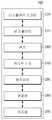
도 12는 본 개시의 일 실시 예에 따른, HMD(100)에서 액티브 소자를 이용하여 시력을 측정하고 보정하는 방법을 설명하기 위한 순서도이다.BRIEF DESCRIPTION OF THE DRAWINGS Figure 1 is a diagram showing a general configuration of a head mounted display (HMD) according to one embodiment of the present disclosure;
FIG. 2A is a block diagram schematically illustrating a configuration of a head mounted display (HMD) according to an embodiment of the present disclosure; FIG.
FIG. 2B is a block diagram schematically showing a configuration of an optical portion of a head mounted display (HMD) according to an embodiment of the present disclosure; FIG.
FIG. 3 is a view for explaining a conventional head-mounted display (HMD)
4 is a diagram illustrating a pupil forming design that is an optical design of a head mounted display (HMD), according to one embodiment of the present disclosure;
5 is a specific configuration diagram of a head mounted display (HMD) according to an embodiment of the present disclosure;
6A and 6B are diagrams for explaining an active element constituting a head mounted display (HMD) according to an embodiment of the present disclosure;
7A to 7E are diagrams for explaining a method of measuring a visual acuity of a user using an active element in a head mounted display (HMD) according to an embodiment of the present disclosure;
8A and 8B are diagrams for explaining implementation of a high-resolution display by high-speed tilting of an active element in a head mounted display (HMD) according to an embodiment of the present disclosure;
9A-9C illustrate a head-mounted display (HMD) controlling focus of a virtual image by an active element, according to an embodiment of the present disclosure;
10A and 10B are views for explaining visual accommodation / convergence according to the distance of a virtual image by a head mounted display (HMD) by an active element, and FIGS.
FIG. 11 is a block diagram of a head mounted display (HMD) for an augmented image using an active element and a diffractive element, according to an embodiment of the present disclosure, and FIG.
12 is a flowchart for explaining a method of measuring and correcting visual acuity using an active element in the
본 명세서에서 사용되는 기술적 용어는 단지 특정한 실시 예를 설명하기 위해 사용된 것으로, 본 개시를 한정하려는 의도가 아님을 유의해야 한다. 또한, 본 명세서에서 사용되는 기술적 용어는 본 명세서에서 특별히 다른 의미로 정의되지 않는 한, 본 개시가 속하는 기술 분야에서 통상의 지식을 가진 자에 의해 일반적으로 이해되는 의미로 해석되어야 하며, 과도하게 포괄적인 의미로 해석되거나, 과도하게 축소된 의미로 해석되지 않아야 한다. 또한, 본 명세서에서 사용되는 기술적인 용어가 본 발명의 사상을 정확하게 표현하지 못하는 잘못된 기술적 용어일 때에는, 당업자가 올바르게 이해할 수 있는 기술적 용어로 대체되어 이해되어야 할 것이다. 또한, 본 개시에서 사용되는 일반적인 용어는 사전에 정의되어 있는 바에 따라, 또는 전후 문맥상에 따라 해석되어야 하며, 과도하게 축소된 의미로 해석되지 않아야 한다.It is noted that the technical terms used herein are used only to describe certain embodiments and are not intended to limit the present disclosure. It is also to be understood that the technical terms used herein are to be interpreted in a sense generally understood by one of ordinary skill in the art to which this disclosure belongs, unless otherwise defined in this specification, Should not be construed to mean, or be interpreted in an excessively reduced sense. Further, when a technical term used herein is an erroneous technical term that does not accurately express the spirit of the present invention, it should be understood that technical terms that can be understood by a person skilled in the art are replaced. In addition, the generic terms used in this disclosure should be interpreted according to predefined or prior context, and should not be construed in an overly reduced sense.
또한, 본 명세서에서 사용되는 단수의 표현은 문맥상 명백하게 다르게 뜻하지 않는 한, 복수의 표현을 포함한다. 본 출원에서, "구성된다" 또는 "포함한다" 등의 용어는 명세서상에 기재된 여러 구성 요소들, 또는 여러 단계들을 반드시 모두 포함하는 것으로 해석되지 않아야 하며, 그 중 일부 구성 요소들 또는 일부 단계들은 포함되지 않을 수도 있고, 또는 추가적인 구성 요소 또는 단계들을 더 포함할 수 있는 것으로 해석되어야 한다.Also, the singular forms "as used herein include plural referents unless the context clearly dictates otherwise. In the present application, the term "comprising" or "comprising" or the like should not be construed as necessarily including the various elements or steps described in the specification, Or may be further comprised of additional components or steps.
또한, 본 명세서에서 사용되는 구성요소에 대한 접미사 "부"는 명세서 작성의 용이함만이 고려되어 부여되거나 혼용되는 것으로서, 그 자체로 서로 구별되는 의미 또는 역할을 갖는 것은 아니다.Further, the suffix "part" for a component used in the present specification is given or mixed in consideration of ease of specification, and does not have a meaning or role that is different from itself.
또한, 본 명세서에서 사용되는 제1, 제2 등과 같이 서수를 포함하는 용어는 다양한 구성 요소들을 설명하는데 사용될 수 있지만, 상기 구성 요소들은 상기 용어들에 의해 한정되어서는 안 된다. 상기 용어들은 하나의 구성요소를 다른 구성요소로부터 구별하는 목적으로만 사용된다. 예를 들어, 본 개시의 권리 범위를 벗어나지 않으면서 제1 구성요소는 제2 구성 요소로 명명될 수 있고, 유사하게 제2 구성 요소도 제1 구성 요소로 명명될 수 있다.Furthermore, terms including ordinals such as first, second, etc. used in this specification can be used to describe various elements, but the elements should not be limited by the terms. The terms are used only for the purpose of distinguishing one component from another. For example, without departing from the scope of the present disclosure, the first component may be referred to as a second component, and similarly, the second component may also be referred to as a first component.
이하에서는, 첨부된 도면을 참조하여 본 개시에 따른 바람직한 실시예를 상세히 설명하되, 도면 부호에 관계없이 동일하거나 유사한 구성 요소는 동일한 참조 번호를 부여하고 이에 대한 중복되는 설명은 생략하기로 한다.Hereinafter, preferred embodiments according to the present disclosure will be described in detail with reference to the accompanying drawings, wherein like reference numerals are used to designate identical or similar elements, and redundant description thereof will be omitted.
또한, 본 발명을 설명함에 있어서 관련된 공지 기술에 대한 구체적인 설명이 본 발명의 요지를 흐릴 수 있다고 판단되는 경우 그 상세한 설명을 생략한다. 또한, 첨부된 도면은 본 발명의 사상을 쉽게 이해할 수 있도록 하기 위한 것일 뿐, 첨부된 도면에 의해 본 발명의 사상이 제한되는 것으로 해석되어서는 아니 됨을 유의해야 한다.In the following description, well-known functions or constructions are not described in detail since they would obscure the invention in unnecessary detail. It is to be noted that the accompanying drawings are only for the purpose of facilitating understanding of the present invention, and should not be construed as limiting the scope of the present invention with reference to the accompanying drawings.
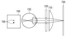
이하에서는, 본 발명의 실시 예를 첨부한 도면을 참조하여 상세히 설명하기로 한다. 도 1은 본 발명의 일 실시 예에 따른, 헤드 마운티드 디스플레이(HMD, Head Mounted Display)의 일반적인 구성을 나타내는 도면이다.Hereinafter, embodiments of the present invention will be described in detail with reference to the accompanying drawings. 1 is a diagram showing a general configuration of a head mounted display (HMD) according to an embodiment of the present invention.
도 1을 참조하면, 헤드 마운티드 디스플레이(HMD, Head Mounted Display)는 쌍안경과 같은 타입의 디스플레이 장치일 수 있다. 그러나, 본 개시는 이에 한정하지 않으며, 헤드 마운티드 디스플레이(HMD, Head Mounted Display)는 머리에 장착할 수도 있고, 일반적인 안경과 같이 가볍고 얇은 구성을 가질 수도 있다.Referring to FIG. 1, a head mounted display (HMD) may be a type of display device such as a binoculars. However, the present disclosure is not limited to this, and a head mounted display (HMD) may be mounted on the head, or may have a light and thin structure such as general glasses.
본 개시의 실시 예에 따라, HMD(100)은 좌우 눈에 이미지를 표시하는 디스플레이, 사용자의 시력을 측정할 수 있는 광학부(미도시)와 제어부(101)로 구성된다. 제어부(101)는 HMD(100)의 외부에 구성될 수도 있고, HMD(100)의 내부에 구성될 수도 있다. 도 2a의 프로세서(220)가 제어부(101)의 기능을 수행할 수 있다. 광학부는 도 2b에서 상세히 설명하기로 한다.According to the embodiment of the present disclosure, the
제어부(101)는 광학부에서 측정한 사용자의 시력을 바탕으로 옵티컬 파워를 조절하여 사용자의 시력을 보정할 수 있다. 또한, 제어부(101)는 측정된 사용자의 시력을 메모리(미도시)에 저장하고, 저장된 사용자 정보를 바탕으로 시력을 측정하도록 광학부를 제어할 수 있다.The
제어부(101)가 HMD(100)의 외부에 구성될 때, HMD(100)는 제어부(101)와 통신을 수행하며, 제어부(101)는 HMD(100)가 영상처리장치(미도시)로부터 영상을 수신하도록 통신을 수행한다. HMD(100)와 제어부(101)는 유선 또는 무선으로 통신하도록 구성될 수 있다.The
또한, 본 개시는 HMD이외에도, 디스플레이 장치에서 사용자의 시력을 측정하고 보정해줄 수 있는 광학계를 가지는 디스플레이 장치 모두에서 적용이 가능하다.Further, the present disclosure is applicable to both a display device having an optical system capable of measuring and correcting the visual acuity of a user in a display device in addition to the HMD.
도 2a는 본 개시의 일 실시예에 따른, HMD의 구성을 간략히 나타내는 블록도이다. 도 2a를 참조하면, HMD(100)는 디스플레이(210), 프로세서(220), 메모리(230), 액티브 소자(240)로 구성될 수 있다.2A is a block diagram briefly illustrating the configuration of an HMD, according to one embodiment of the present disclosure; Referring to FIG. 2A, the
디스플레이(210)는, 이미지를 제공하며, 프로세서(220)의 제어 명령에 따라, 액티브 소자(240)를 이용하여 측정한 사용자의 좌우 시력 및 메모리(230)에 저장된 사용자 정보를 바탕으로 사용자의 시력에 맞는 보정된 영상을 표시할 수 있다.The
그리고 디스플레이(210)는 LCD, OLED, 플렉서블 디스플레이, 3차원 디스플레이 등 다양한 형태로 구현될 수 있다. 디스플레이(210)는 터치 스크린으로 구성되어 출력 장치뿐만 아니라 사용자의 터치 명령을 입력 받는 입력 장치로도 사용될 수 있다.The
메모리(230)는, 프로세서(220)에 의해 생성된 사용자 시력 정보 및 생체 정보를 저장할 수 있다. 또한 메모리(230)는 사용자의 보정된 시력 정보를 저장할 수 있다. 메모리(230)는 프로세서(220)에서 사용하는 프로그램, 연산 파라미터, 사용자 명령어 등을 저장할 수 있다. 메모리(220)는, 예를 들어, 하드디스크, 멀티미디어 카드, 플래시 메모리, 마이크로, SD 카드, XD 카드 등의 저장 매체 중 적어도 하나일 수 있다. 또한 메모리(230)는 프로세서(220) 내부의 램(RAM) 또는 롬(ROM) 등이 될 수도 있다.The
액티브 소자(240)은 사용자의 옵티컬 파워를 조절하여 초점을 가변시킬 수 있고, 기울기의 변형이 가능한 거울(deformable mirror)를 포함한다. 액티브 소자(240)는 복수 개의 마이크로 미러(micro-mirrors)로 구성되며 디스플레이(210)에서 제공된 이미지를 반사한다. 본 개시에서는 액티브 소자(240)로서 마이크로 미러로 구성된 MEMS 미러(Micro-electromechanical systems Mirror)를 이용한 실시예를 설명하기로 한다. 액티브 소자(240)에 대해서는 도6a 및 도6b에서 상세히 설명하기로 한다.The
프로세서(220)는, 액티브 소자(240)를 제어하여 사용자의 시력을 검출하고, 검출된 사용자의 시력에 기반하여 액티브 소자(240)의 복수의 마이크로 미러 중 적어도 일부의 기울기를 제어하여 디스플레이(210)에서 제공된 이미지의 초점 거리를 조절할 수 있다.The
프로세서(220)는, 시력 측정 광선을 생성하도록 디스플레이(210)를 제어하고, 시력 측정 광선이 액티브 소자(240)의 복수 개의 마이크로 미러 중 적어도 하나를 통해 사용자의 망막에 결상하도록 액티브 소자(240)를 제어할 수 있다. 그리고, 프로세서(220)는 사용자의 망막에 결상하는 시점의 액티브 소자(240)에서 검출된 정보를 바탕으로 사용자의 시력 정보로 메모리(230)에 등록할 수 있다.The
프로세서(220)는, 디스플레이(210)에서 방출하는 시력 측정을 위한 광선 중 일부 영역만 사용자의 망막에 결상하도록 액티브 소자(240)에 마스크(mask) 패턴을 생성하고, 액티브 소자(240)의 옵티컬 파워를 가변하여 시력을 검출할 수 있다. 그리고 프로세서(220)는 검출된 시력을 바탕으로 액티브 소자(240)의 옵티컬 파워를 조절하여 사용자의 시력을 보정할 수 있다.The
또한, 프로세서(220)는, 디스플레이(210)에 표시되는 가상(Virtual Reality) 영상의 초점을 지정된 시간에 가변할 수 있다. 그리고, 프로세서(220)는 영상 인식에 의해 디스플레이(210)에 표시되는 가상 영상의 물체의 위치를 추정하여 영상의 초점을 가변하여 가상 영상의 초점 거리를 가변할 수 있다.In addition, the
그리고 프로세서(220)는, 가상 영상의 물체의 거리에 비례하도록 액티브 소자의 파워를 가변하여 가상 영상의 각 레이어별 초점을 조절할 수 있다. 또한, HMD(100)의 사용자가 근시일 때, 프로세서(220)는 렌즈의 파워에 오프셋을 지정하여 액티브 소자(240)의 파워가 가변함에 따라 사용자의 시력 조절 범위를 확대할 수 있다.The
프로세서(220)는 사용자의 명령을 입력 받아 액티브 소자를 구성하는 마이크로 미러의 기울기가 가변되어 사용자의 시력을 측정되도록 구현될 수 있다. 예를 들어, 프로세서(220)는 시력 측정을 위한 UI(User Interface) 또는 메뉴 버튼 등을 통해 사용자에 의해 액티브 소자를 구성하는 마이크로 미러의 기울기를 가변되도록 구현될 수 있다.HMD(100)는 통신부(미도시)를 포함할 수 있다. 통신부는 외부 전자 장치 및 유/무선 데이터 통신을 수행할 수 있다. 무선 통신 방식으로 외부 전자 장치와 데이터 통신을 수행할 경우, 통신부는 와이파이 다이렉트(WIFI DIRECT) 통신 모듈, 블루투스 모듈, 적외선 통신(IrDA, infrared data association) 모듈, NFC(Near Field Communication) 모듈, 지그비(Zigbee) 모듈, 셀룰러 통신 모듈, 3G(3세대) 이동통신 모듈, 4G 이동 통신 모듈, LTE(Long Term Evolution) 통신 모듈 중 적어도 하나를 포함할 수 있다.The
여기서, 유선 통신 방식으로 외부 전자 장치와 데이터 통신을 수행할 경우, 통신부는 USB와 같은 인터페이스 모듈을 포함할 수 있으며, 이 같은 인터페이스 모듈을 통해 PC와 같은 외부 단말 장치와 물리적으로 연결되어 영상 데이터를 송수신하거나, 펌웨어 업그레이드를 수행하기 위한 펌웨어 데이터를 송수신할 수 있다.Here, when performing data communication with an external electronic device through a wired communication method, the communication unit may include an interface module such as a USB, and is physically connected to an external terminal device such as a PC through the interface module, And send / receive firmware data to perform firmware upgrade.
이를 통해, 본 개시의 일 실시예에 따른 HMD(100)는, 액티브 소자(240)를 이용하여 사용자의 시력을 측정하여 사용자에 맞는 최적의 이미지를 제공할 수 있다.Accordingly, the
도 2b는, 본 개시의 일 실시 예에 따른, 헤드 마운티드 디스플레이(HMD, Head Mounted Display)의 광학부의 구성을 간략히 나타내는 블록도이다.2B is a block diagram briefly showing a configuration of an optical section of a head mounted display (HMD) according to an embodiment of the present disclosure.
도 2b를 참조하면, 광학부(260)는 액티브 소자(240), 디스플레이 스크린(270), 빔 스플리터(275), 렌즈(280), 렌즈 미러(285), 복수의 편광판(quarter wave plate, half wave plate)(290) 및 프리즘(295)을 포함할 수 있다. 광학부(260)를 구성하는 구성요소들은 이에 한정되지 않고 다른 구성 요소들이 더 포함될 수도 있다. 각 구성 요소의 특징에 대해서는 도 5에서 구체적으로 설명하기로 한다.2B, the
디스플레이 스크린(270)은 HMD(100)의 각각 좌우의 눈에 광선을 생성할 수 있다. 디스플레이 스크린(270)은 평면(planar)일 수도 있고 곡면(curve)일 수도 있다. 디스플레이 스크린(270)은 각각 좌우 눈에 하나를 포함하는 표시 광학계일 수 있고, 각각 좌우 눈에 두 개를 포함하는 표시 광학계일 수도 있다. 본 개시에서는 디스플레이 스크린(270)이 각각 좌우 눈에 하나를 포함하는 실시 예를 설명하기로 한다.The
빔 스플리터(275)는 디스플레이 스크린(270)에서 방출하는 광선을 반사할 수 있는 제1 빔 스플리터 및 액티브 소자(240)에서 방출한 광선을 반사할 수 제2 빔 스플리터를 포함할 수 있다. 렌즈(예를 들어, 오목렌즈, 볼록렌즈, 실린더 렌즈)(280)는 빔 스플리터(275)에서 반사한 광선을 수렴(convergence)시킬 수 있다. 액티브 소자(240)는 렌즈(280)에서 방출한 광선을 수렴(convergence) 혹은 발산(divergence)하여 반사할 수 있다. 렌즈 미러(285)는 빔 스플리터(275)에서 반사한 광선을 수렴하여 사용자에게 방출할 수 있다.
편광판(290)은 복수의 편광판(quarter wave plate, half wave plate)을 포함할 수 있다. 프리즘(295)은 사용자의 화각을 넓힐 수 있다. 프리즘(295)은 디스플레이 스크린(270)으로부터 수렴한 광선을 확대해 사용자의 눈동자로 유도할 수 있는 자유 곡면 프리즘일 수 있다.The
도 3은 종래 기술의 시력 조절이 가능한 HMD 를 설명하기 위한 도면이다.3 is a view for explaining an HMD capable of adjusting the visual acuity of the prior art.
도 3을 참조하면, 종래에는, HMD(100)의 광학계를 구성하는 렌즈 미러(301)와 디스플레이 스크린(300)을 동일 광로상에 배치하고, 렌즈 미러(301)와 디스플레이 스크린(300) 사이의 거리인 광로 길이를 조절하여 사용자의 시력을 보정하였다.3, the
그리고 종래에는 HMD(100)의 광학계를 구성하는 디스플레이 스크린(300), 렌즈 미러(301), 및 반사경(미도시)를 동일 광로상에 배치하고, 디스플레이 스크린(300)으로부터 반사경(미도시)까지의 제1 광로 길이와 반사경(미도시)로부터 렌즈 미러(301)까지의 제2 광로 길이 중 적어도 한쪽을 조절하여 사용자의 시력을 보정하였다.Conventionally, the
그러나, 상술한 기술들은 사용자의 시력을 정밀하게 측정하는 것이 불가능하며, HMD(100)를 사용하는 사용자가 변동될 때 자동으로 사용자의 시력을 보정하지는 못하는 문제점이 있다.However, the above-described techniques can not precisely measure the user's visual acuity and can not correct the user's visual acuity automatically when the user using the
도 4는 본 개시의 일 실시예에 따른, HMD(100)의 광학 디자인(optical design)인 중 하나인 동공 형성(pupil forming) 디자인을 설명하기 위한 도면이다.FIG. 4 is a diagram illustrating a pupil forming design that is one of the optical design of the
HMD(100)를 위한 광학 디자인은 비-동공 형성 디자인(non-pupil forming design)와 동공 형성 디자인(Pupil forming design)이 있다. 비-동공 형성 디자인은 설계가 쉽다. 반면, 비-동공 형성 디자인은 짧은 경로 길이(short path length)를 가지므로, 소스 이미지와 가상의 이미지 사이의 짧은 투사 거리(a short throw distance)를 갖는다. 경로 길이가 짧다는 것은 HMD(100)의 디스플레이가 사용자의 안면과 눈에 가까이 위치한다는 것을 의미하며, 이러한 HMD(100)의 광학 디자인은 변경 설계가 어려운 단점이 있다.The optical design for the
반면, 동공 형성 디자인은, 현미경(microscope), 쌍안경(binoculars), 또는 잠수함의 잠망경(periscope)에서 이미지를 생성하는 것과 유사한 구성을 가진다. 도4를 참조하면, 동공 형성 디자인은 제1 렌즈 세트(401)에서 디스플레이(400)로부터 보내는 소스 이미지의 중간 이미지(402)를 생성한다. 생성된 중간 이미지(402)는 제2 렌즈 세트(403)에 의해 사용자의 동공(404)에 릴레이(relay)된다. 사용자의 눈(404)은 가상의 이미지인 동공 사출(exit pupil) 영역에 위치한다.Pupil-forming designs, on the other hand, have a similar configuration to creating images in a microscope, binoculars, or subscope of a submarine. 4, a pupil-forming design creates an
동공 형성 디자인의 장점은 이미지 평면(image plane)으로부터 사용자의 눈까지 많은 경로 길이(path length)를 제공한다. 또한 동공 형성 디자인은 비-동공 형성 디자인보다 더 긴 경로 길이를 제공하여 사용자의 안면으로부터 멀리 움직일 수 있도록 구현할 수 있다. 또한, 동공 형성 디자인은 더 많은 렌즈와 미러(mirrors)를 삽입할 수 있으므로 옵티컬 코렉션(optical correction)을 개선시킬 수 있다.The advantage of the pupil-forming design is that it provides many path lengths from the image plane to the user's eye. Pupil-forming designs can also be implemented to provide a longer path length than the non-papillary design and move away from the user ' s face. In addition, the pupil-forming design can incorporate more lenses and mirrors to improve optical correction.
도 5는 본 개시의 일 실시 예에 따른, HMD 디스플레이 광학계(display optics)의 구체적인 구성도이다.5 is a specific configuration diagram of an HMD display optics according to an embodiment of the present disclosure.
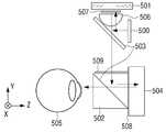
도 5를 참조하면, HMD(100)의 광학계(optics)는 디스플레이(500), 액티브 소자(501), 프리즘(502), 편광 빔 스플리터(503), 렌즈 미러(504), 렌즈(506), 제1편광판(507), 제2 편광판(508), 제3 편광판(509)을 포함한다.5, the optics of the
디스플레이(500)는 평면 디스플레이(planar display)이거나 곡면 디스플레이(curve display)일 수 있다. 디스플레이(500)는 LCD, OLED, 등의 액정 디스플레이일 수 있다.The
액티브 소자(501)는 수천 개의 마이크로 미러(micro mirrors)로 구성된 MEMS 미러로 구현될 수 있다. 수천 개의 조각들로 이루어진 마이크로 미러는 X축 또는 Y축으로 회전하며 옵티컬 파워(optical power)를 조절하고 마스크 패턴(mask pattern)을 가변시킬 수 있다.The
HMD(100)는 액티브 소자(501)의 수천 개의 마이크로 미러 중 적어도 일부의 기울기를 제어하여 가변된 옵티컬 파워를 바탕으로 생성된 마스크 패턴으로 사용자의 시력을 검출할 수 있다. 또한, 검출된 시력을 바탕으로 액티브 소자(501)의 수천 개의 마이크로 미러 중 적어도 일부의 기울기를 제어하여 디스플레이에 제공된 이미지의 초점 거리를 조절하여 사용자의 시력을 보정할 수 있다.The
이를 통해, HMD(100)는 사용자의 시력을 정밀하게 측정하고 보정할 수 있다. 또한, HMD(100)는 마이크로 미러에 의한 정밀한 시력 측정으로 공차(tolerance)를 줄일 수 있다. 액티브 소자(501)의 마스크 패턴을 가변하여 시력을 측정하는 방법에 대해서는 도 7a 내지 도 7e에서 상세히 설명하기로 한다.Thereby, the
액티브 소자(501)는 광로상에 수직으로 배치하며, 디스플레이(500)와도 수직으로 배치된다. 액티브 소자(501)의 구성에 대한 구체적인 설명은 도6a 및 도6b에서 후술하기로 한다The
프리즘(502)은 사용자의 화각을 넓혀주는 역할을 한다. 편광 빔 스플리터(503)는 빛을 투과 또는 반사하여 입사광을 분리하는 역할을 하고, 판형(planar) 또는 큐브형(cube) 빔 스플리터를 사용할 수 있다.The
렌즈 미러(504)는 오목렌즈 거울, 볼록 렌즈 거울, 그리고 실린더 렌즈 거울일 수 있다. 렌즈(506)는 오목 렌즈(convex lenses), 볼록 렌즈(concave lenses), 그리고 실린더 렌즈(cylinder lenses)일 수 있다. 렌즈(506) 및 렌즈 미러(504)는 단일 구성일 수도 있고, 상이한 렌즈를 복수로 구성할 수도 있다.The
제1편광판(507) 및 제3편광판(509)는 1/4파장판(quarter wave plate)이고, 제2 편광판(508)은 1/2파장판(half wave plate)으로 구성될 수 있다. 1/4파장판(507, 509)와 1/2파장판(508)은 입사하는 광선의 상태에 따라 다양한 편광 상태를 만든다.The first
디스플레이(500)는 광선을 방출하고, 액티브 소자(501)의 앞면에 배치된 제1 편광 빔 스필리터(polarized beam splitter)(503)는 디스플레이(500)가 방출한 광선을 반사한다. 제1 편광 빔 스플리터(503)가 반사한 광선은 렌즈(506)에서 수렴하여 1/4 파장판(quarter wave plate)를 통과해 액티브 소자(501)에 수렴된다.The
액티브 소자(501)는 렌즈(506)에서 방출한 광선을 수렴(convergence) 또는 발산(divergence)하여 반사한다. 액티브 소자(501)에서 발산한 광선은 1/4파장판(quarter wave plate)를 통과해 렌즈(506)에 수렴된다. 렌즈(506)에 수렴된 빛은 제1 편광 빔 스플리터(503)를 지나 1/2 편광판(half wave plate)를 통과하여 제2 편광 빔 스플리터(503)을 통해 반사되어 1/4 파장판(508)을 통과하여 렌즈 미러(504)에 입사된다. 렌즈미러(504)는 입사한 광선을 반사하고, 렌즈미러(504)에서 반사된 광선은 1/4 파장판(508)을 통과하여 제2 편광 빔스플리터(503)를 통과하여 사용자의 망막(505)에 결상된다.The
구체적으로 예를 들어, 디스플레이(500)에 X 편광을 방출할 때, X편광은 제1 편광 빔스플리터에서 반사되어 액티브 소자(501)로 입사된다. 이때, 액티브 소자(501)에 입사되기 전 1/4 파장판(507)을 통과하고, 액티브 소자(501)에서 반사한 광선은 또다시 1/4파장판(507)을 통과하여, Y 편광이 제1 편광 빔스플리터(503)를 통과한다.Specifically, for example, when emitting X polarized light to the
제1 편광 빔스플리터(503)를 통과한 Y 편광은 1/2파장판(509)에 입사될 때 가상의 이미지를 생성하고, 1/2파장판(509)을 통과한 Y편광은 X편광으로 렌즈 미러(504)에 입사된다. X편광으로 입사되는 광선은 1/4파장판(508)을 두번 통과하여(입사/반사), 렌즈 미러(504)로부터 동공(505)에 Y편광을 발산한다.The Y polarized light having passed through the first
이때, 동공 형성 디자인에 따른 본 개시의 실시예에 따라, 사용자는 동공 사출(pupil exit)에서 가상의 이미지를 볼 수 있다.At this time, according to the embodiment of the present disclosure according to the pupil forming design, the user can view a virtual image at a pupil exit.
도 6a 및 도 6b는, 본 개시의 일 실시예에 따른, HMD를 구성하는 액티브 소자를 설명하기 위한 도면이다.6A and 6B are views for explaining an active element constituting an HMD according to an embodiment of the present disclosure.
도 6a는, 본 개시의 일 실시예에 따른, 액티브 소자인 MEMS 미러가 이미지를 결상하는 것을 설명하기 위한 도면이다. 도 6a를 참조하면, MEMS 미러(610)는 복수의 마이크로 미러(601)로 구성된다. MEMS 미러(610)는 마이크로 미러(601)의 위치가 제어되어 임의의 흩어진 광들이 이미지 면(image plane)의 한 점 P(600)에 수렴된다.6A is a diagram for explaining how an MEMS mirror, which is an active element, imaged an image, according to an embodiment of the present disclosure. Referring to FIG. 6A, the
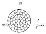
도 6b는, 본 개시의 일 실시예에 따른, 액티브 소자인 MEMS 미러(610)의 평면도를 도시한 도면이다. 도6b를 참조하면, MEMS 미러(610)는 마이크로미러(620)의 원형 배열로 구성되고, 마이크로미러(620)는 거울(mirror)과 동일한 기능을 가진다. 마이크로미러(620)는 높은 반사도를 가진다. 각각의 마이크로미러(620)는 광학 효율성(optical efficiency)을 향상시킬 수 있는 반사 영역(reflective area)을 증가시키기 위해서 팬 모양(fan shape)을 가질 수 있다. 그러나, 원형 배열 및 팬 모양의 구성은 본 개시를 설명하기 위한 일 실시 예일 뿐 이에 한정되지 않는다.6B is a top plan view of a
MEMS 미러 배열을 지닌 렌즈(액티브 소자)는 마이크로미러(620)가 매우 가볍고 작기 때문에(a tiny mass) 매우 빠른 반응 속도를 가진다. 예를 들어, 마이크로미러(620)의 반응 속도는 10KHz를 초과할 수 있다. 따라서, 마이크로미러(620)의 초점거리 변화 속도는 10KHz와 같거나 그보다 크도록 구현할 수 있다.The lens (active element) with the MEMS mirror array has a very fast response speed because the
또한 마이크로미러(620)는 렌즈의 초점 거리(focal length)를 변화시키도록 제어한다. MEMS 미러(610)는 초점 거리(focal length)를 변화시키기 위해, 각각의 마이크로 미러(620)의 병진운동(translation)이나 회전운동(rotation)을 제어한다. 마이크로미러(620)의 회전운동은 X축 및 Y축 방향으로 광의 방향을 변화시키고, 병진운동은 Z축 방향으로 광의 위상을 조절한다.Also, the
따라서, 복수의 마이크로미러(620)로 구성된 평면(planar) MEMS 미러(610)를 HMD(100)의 광로상에 수직으로 배열하여, 시력 측정을 위한 특정 광선만 MEMS 미러(620)의 중심 부근에 맺도록 구현할 수 있다. 이를 통해, 디스플레이에서 방출하는 광선 중 시력 측정용 주광선(chief lay)만 사용자의 망막에 결상하도록 하여 시력을 측정할 수 있다.Therefore, a
또한, 마이크로미러(620)의 회전운동 및 병진운동을 통해 초점 거리(focal length)를 가변하여 옵티컬 파워(optical power)를 조절할 수 있다. 이를 통해 시력을 보정할 수 있다.Further, the optical power can be adjusted by varying the focal length through the rotational and translational movements of the
도 7a 내지 도 7e는, 본 개시의 일 실시예에 따른, HMD에서 액티브 소자를 이용하여 사용자의 시력을 측정하는 방법을 설명하기 위한 도면이다.7A to 7E are views for explaining a method of measuring a visual acuity of a user using an active element in an HMD, according to an embodiment of the present disclosure.
도 7a는 광학계(optics)를 이용하여 시력을 측정할 때, 사용자의 시력에 따라 액티브 소자에 의해 마스크 패턴이 가변하는 것을 설명하기 위한 도면이다.7A is a view for explaining that a mask pattern is varied by an active element according to a user's visual acuity when measuring visual acuity using an optics.
도 7a를 참조하면, 디스플레이 스크린(700)에서 광선을 방출할 때, 디스플레이(700)에서 픽셀(701)이 온(On)되고, 온(On)된 점상의 픽셀(701)이 렌즈부에 입사된다. 디스플레이 스크린(700)에서 방출한 광선이 렌즈를 통과하면, 점상 광선인 픽셀(701)의 크기가 렌즈에 의해 확장된 점상 광선(702)이 된다. 렌즈를 통과한 광선(702)이 액티브 소자에 입사되면, 액티브 소자의 마이크로미러의 회전 운동 및 공진 운동에 의해 특정 광선만 액티브 소자의 중심 부근에 마스크 온(mask on)된다. 따라서, 렌즈를 통과한 점상의 광선(702) 중 특정 영역의 광선(703)이 액티브 소자에 결상된다. 액티브 소자에 결상된 특정 영역의 광선(703)은 렌즈로 발산되고 나머지 영역의 광선은 렌즈에 투과되지 않는다. 따라서, 액티브 소자를 통과한 후의 광선은 액티브 소자에서 결상되었던 특정 영역의 점상(704)이 된다.7A, when a light is emitted from the
시력 측정의 원리인 Scheiner's principle에 의해, 일반적인 시력 측정 방법은 정상 시력일 때 광선이 한 점(705)에 모이게 되고, 근시나 원시는 광선(706)이 분리되어 시력이 측정된다.According to Scheiner's principle, which is the principle of visual acuity measurement, a general visual acuity measurement method is that a light ray is collected at one point (705) at a normal visual acuity, and a light ray (706)
본 개시의 일 실시 예에 따라, Scheiner's principle을 적용하여, HMD(100)는 액티브 소자를 이용하여 시력 측정을 위한 광선만 눈의 망막의 중심에 맺히도록 마이크로 미러 중 적어도 일부의 기울기를 제어하고, 그 이외의 광선은 중심에서 멀어지도록 구동하여 시력 측정을 할 수 있다.According to one embodiment of the present disclosure, applying the Scheiner's principle, the
본 개시의 실시 예에 따른, HMD(100)는 액티브 소자를 이용하여 수동으로 시력 측정이 이루어질 수 있다. 즉, HMD(100)는 사용자의 명령을 입력 받아 액티브 소자를 구성하는 마이크로 미러의 기울기가 가변되어 사용자의 시력을 측정되도록 구현될 수 있다.In accordance with the embodiment of the present disclosure, the
예를 들어, HMD(100)는 시력 측정을 위한 UI(User Interface) 또는 메뉴 버튼 등을 통해 사용자에 의해 액티브 소자를 구성하는 마이크로 미러의 기울기를 가변되도록 구현될 수 있다. 이때, 시력 측정을 위한 UI(User Interface) 또는 메뉴 버튼은 HMD(100) 내에 구현될 수도 있고 외부 장치(예를 들어, 리모컨 등)에 의해 구현될 수도 있다.For example, the
구체적으로, 사용자는 HMD(100)의 스크린을 터치하거나 메뉴 버튼 등을 조작하면서 액티브 소자를 구성하는 마이크로 미러의 기울기를 변화시킬 수 있다. 사용자는 액티브 소자를 구성하는 마이크로 미러의 기울기를 사용자의 시력에 맞도록 가변하는 동안, HMD(100)로부터 선명한 패턴이 보이는 순간을 사용자의 시력으로 저장할 수 있다. 사용자로부터 시력 저장 명령이 입력될 때, HMD(100)는 액티브 소자를 구성하는 마이크로 미러의 기울기 정보 등을 바탕으로 검출된 시력 정보를 저장할 수 있고, 사용자 정보(예: 사용자 ID, 사용자 생체 정보 등)와 함께 시력정보가 저장되도록 구현될 수도 있다. 이때, 사용자 정보는 사용자에 의해 HMD(100)에 기저장된 사용자 정보일 수 있고, 사용자에 의해 시력정보와 함께 입력되는 정보일 수 있다.Specifically, the user can change the tilt of the micromirror constituting the active element by touching the screen of the
도 7b 내지 도 7e는, 본 개시의 일 실시 예에 따라, 정상 시력과 원시의 시력을 측정될 때, 액티브 소자에 의한 마스크 패턴의 가변을 설명하기 위한 도면이다.도 7b 및 도 7c는, 정상 시력을 측정할 때의 액티브 소자에 의한 마스크 패턴을 나타내는 도면이다.7B-7E are views for explaining the variation of the mask pattern by the active element when the normal visual acuity and the raw visual acuity are measured, according to an embodiment of the present disclosure. Fig. 8 is a view showing a mask pattern by an active element when measuring visual acuity; Fig.
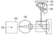
도7b 및 도7c를 참조하면, 도7a에서 설명한 디스플레이 스크린(700)에서 방출한 점상의 광선(701)은 렌즈(710)를 통과하면서 확대된다. 도 7a에 상술한 바와 같이, 렌즈를 통과한 광선은 확대된 점상(702)이다. 렌즈에서 발산한 광선(702)는 액티브 소자(720)에 입사된다.7B and 7C, the point light rays 701 emitted from the
액티브 소자(720)에 입사된 광선(702)은 액티브 소자(720)를 구성하는 수천 개의 마이크로미러의 병진운동(translation) 및 회전운동(rotation)에 의해 마스크 패턴을 가변시킬 수 있다. 이에 따라, 사용자의 초점 거리에 따른 특정 영역만의 광선만이 액티브 소자(720)에 결상된다.The
도 7a에 상술한 바와 같이, 액티브 소자에 결상된 광선은 특정 광선에 대하여 마스크 패턴(703)을 가진다. 또한, 액티브 소자를 통과한 후의 광선은 액티브 소자에서 결상되었던 특정 영역의 점상(704)이 된다. 도 7b 및 도 7c를 참조하면, 액티브 소자(720)를 통과한 광선(704)(도 7a)은 사용자의 망막(730)의 중심에 맺히고, 사용자의 시력 측정용 광선(705)이 디스플레이 스크린(700)에 생성되어 시력이 측정될 수 있다.As described above with reference to Fig. 7A, the light beam focused on the active element has a
도 7d 및 도7e는, 근시인 시력을 측정할 때의 액티브 소자에 의한 마스크 패턴을 나타내는 도면이다.Figs. 7D and 7E are diagrams showing a mask pattern by the active element when measuring near-vision visual acuity. Fig.
도 7d 및 도 7e를 참조하면, 액티브 소자(720)는 렌즈(710)에서 수렴한 광선(702)에 대해 액티브 소자(720)를 구성하는 마이크로 미러의 회전 운동 및 병진 운동에 의해 정상 시력(도 7b 및 도 7c)과는 상이한 마스크 패턴을 생성한다. 이때, 도 7a에서 설명한 액티브 소자(720)에 결상되어 생성된 마스크 패턴을 지닌 광선(704)은, 도 7d 및 도 7e에서 사용자의 망막(730)의 앞 부분에 맺히고, 사용자의 시력 측정용 광선(706)이 분리되어 생성되고, 이를 이용해 근시 시력이 측정될 수 있다. 또한, 난시 측정은 액티브 소자(720)에 의해 생성되는 마스크 패턴의 방위각의 회전에 의해 생성되는 마스크 패턴을 조절하여 측정될 수 있다.7D and 7E, the
상술한 바와 같이, HMD(100)는 시력 측정 광선을 생성하도록 디스플레이 스크린(700)를 제어하고, 시력 측정 광선이 액티브 소자(720)를 통해 사용자의 망막(730)에 결상하도록 액티브 소자(720)를 제어하며, 사용자의 망막(730)에 결상하는 시점의 액티브 소자(720)에 대한 정보를 사용자의 시력 정보로 등록할 수 있다.The
이때, 측정된 시력 정보는 HMD(100)의 메모리에 저장된다. 메모리에는 사용자의 생체 정보를 함께 저장할 수 있다. 예를 들어, 사용자의 생체 정보는 홍채 인식, 음성 인식, 얼굴 인식, 지문 인식 등 다양한 정보를 저장할 수 있다. 따라서, 사용자가 동일한 HMD(100)를 재사용할 때, HMD(100)는 사용자의 생체 정보를 바탕으로 자동으로 사용자의 시력 정보에 적합하도록 시력을 보정할 수 있다.At this time, the measured visual acuity information is stored in the memory of the
구체적으로, HMD(100)는 사용자의 생체 정보를 인식할 때, 사용자가 매뉴얼을 통해 인식 실행을 선택할 수도 있고, 사용자가 HMD(100)를 머리에 장착할 때 자동으로 인식할 수도 있다. HMD(100)는 사용자에 대해 인식이 완료되면, 메모리에 저장된 사용자의 생체 정보에 매칭되는 사용자의 시력 정보를 바탕으로 시력을 보정할 수 있다. HMD(100)에 사용자의 생체 정보를 저장하고 인식하는 기술이 적용됨에 따라 사용자의 정보를 보호하는 암호화 기술이 적용될 수도 있다.Specifically, when the
본 개시의 일 실시 예에 따라, HMD(100)에서 사용자의 시력을 보정하는 방법은, 액티브 소자가 사용자의 옵티컬 파워(optical power)를 조절하여 사용자의 시력을 보정할 수 있다.According to one embodiment of the present disclosure, a method of correcting the user's visual acuity in the
옵티컬 파워는 렌즈 파워를 의미하며, 초점거리(focal length)에 반비례한다. 따라서, HMD(100)는 사용자의 시력에 따라 상이한 초점거리를 가진다. 복수의 마이크로미러로 이루어진 액티브 소자는 사용자의 시력을 바탕으로 나타나는 상이한 초점거리를 제어할 수 있다. 도6a에 도시된 바와 같이, MEMS 미러로 구성된 액티브 소자는 마이크로미러의 회전운동으로 광의 방향을 변화시키고, 병진운동으로 광의 위상을 조절하여 액티브 소자의 초점거리를 가변하여 시력을 보정할 수 있다.Optical power means lens power and is inversely proportional to the focal length. Thus, the
또한, 본 개시의 다른 일 실시 예로, HMD(100)는 가상(Virtual Reality) 영상의 초점을 가변하여 눈의 피로를 개선할 수 있다. HMD(100)를 장시간 사용하는 경우, 가상(Virtual Reality) 영상의 초점 거리를 한 곳에 고정하게 된다. 이때, 한 곳에 초점이 장시간 머물게 되어 눈의 피로도가 발생하고 이에 따른 시력 감퇴의 가능성이 있다.In addition, in another embodiment of the present disclosure, the
상술한 문제점을 해결하기 위하여, 본 개시의 일 실시 예에 따라, HMD(100)는 액티브 소자를 제어하여 지정된 시간마다 임의로 가상 영상의 초점을 가변할 수 있다. 즉, HMD(100)는 특정 시간마다 액티브 소자의 옵티컬 파워를 조절하여 가상 영상의 초점을 조절할 수 있다. 또한, HMD(100)는 디스플레이 스크린에 표시되는 물체의 위치를 추정하여 영상 인식 기술을 적용하여 가상 영상의 초점을 가변할 수도 있다. 이때, 액티브 소자를 이용하여, 주변(ambient) 물체의 위치에 가상 영상의 초점을 일치시킴으로써 눈의 피로를 감소시킬 수 있다.In order to solve the above-described problems, according to one embodiment of the present disclosure, the
본 개시의 다른 실시 예로, 예를 들어, 근시 사용자의 시력이 도수 -3D(diopter)인 경우, 가상의 물체는 약 33cm에 형성된다. 이때, 정상 시력자가 갖는 무한대의 물체거리와 같은 도수 3D(diopter) 변이(disparity)를 적용할 경우, 근시 사용자는 어지러움을 느낄 수 있다. 따라서, 사용자의 시력에 맞게 변이(Disparity)를 조절한 영상을 제공하여 영상 왜곡에 대해 최적 값을 적용하도록 구현할 수 있다.In another embodiment of the present disclosure, for example, if the visual acuity of the near vision user is a diopter of -3 degrees, a hypothetical object is formed at about 33 cm. At this time, when a diopter disparity such as an infinite object distance possessed by a normal eye viewer is applied, nearsightedness users may feel dizziness. Accordingly, it is possible to implement an image in which the disparity is adjusted according to the visual acuity of the user, so that the optimal value is applied to the image distortion.
또한, 본 개시의 다른 실시 예로, HMD(100)는 고차 수차를 보정할 수 있다. 교정 렌즈의 경우 눈의 전체 영역을 측정할 수 없기 때문에 저차 수차(low aberration) 보정만이 가능하다. 그러나 액티브 소자는 복수의 MEMS 미러로 구성되어 각각의 마이크로 미러의 영역마다 초점거리를 조절하여 다른 렌즈 파워를 인가할 수 있으므로 고차 수차 보정이 가능하다. 이를 통해, 눈의 모든 영역을 측정하도록(full aberration finger print of the eye) 구현된 고차 수차량 검출 기술을 적용하여 고차 수차를 검출하고, 액티브 소자를 이용하여 고차 수차를 보정할 수 있다.Further, in another embodiment of the present disclosure, the
그리고 본 개시의 다른 실시 예로, HMD(100)는 광학계를 구성하는 렌즈 미러의 렌즈 파워에 오프셋 값을 설정하여 시력 조절 범위를 확대할 수 있다. 예를 들어, 액티브 소자를 구성하는 복수의 MEMS 미러는 옵티컬 파워가 증가할 때, 회절에 의해 색수차량(chromatic aberration)이 증가한다. 따라서, HMD(100)는 색수차량(chromatic aberration)을 감소시키기 위해서는 낮은 옵티컬 파워로 구동되어야 한다. 옵티컬 파워는 초점 거리에 반비례하므로, 초점 거리가 클 때 옵티컬 파워는 낮은 값을 지닌다.In another embodiment of the present disclosure, the
HMD(100)에서 초점 거리를 증가시키기 위해서, 렌즈 미러에 옵티컬 파워 오프셋을 설정하고, 렌즈 미러에 설정된 오프셋 크기의 옵티컬 파워를 액티브 소자에서 마이너스할 수 있다.In order to increase the focal distance in the
예를 들어, 정상 시력자의 눈이 도수 60D(Diopter)이고, 렌즈 미러의 옵티컬 파워가 27D(Diopter)일 때, 액티브 소자의 MEMS 미러가 사용 가능한 옵티컬 파워는 +3D부터 -3D(Diopter)라고 가정할 수 있다. 렌즈 미러에 옵티컬 파워의 오프셋 값을 설정하지 않은 경우, 정상 시력을 측정할 때, 렌즈 미러는 27D(Diopter)의 옵티컬 파워를 가지고, MEMS 미러는 +3D부터 -3D(Diopter)를 가진다. 이때, 근시인 시력을 측정할 때, 렌즈 미러는 27D의 옵티컬 파워를 가지고, MEMS 미러는 0D부터 -3D까지의 시력을 보정할 수 있다.For example, assuming that the optical power available for the MEMS mirror of the active element is + 3D to -3D (Diopter) when the eye of a normal eye is 60D (Diopter) and the optical power of the lens mirror is 27D (Diopter) can do. When the optical power offset is not set for the lens mirror, the lens mirror has optical power of 27D (Diopter) and the MEMS mirror has + 3D to -3D (Diopter) when measuring normal vision. At this time, when measuring myopic vision, the lens mirror has an optical power of 27D, and the MEMS mirror can correct the vision from 0D to -3D.
반면, 본 개시의 일 실시예에 따라, 렌즈 미러에 옵티컬 파워의 오프셋 값을 설정할 경우, 정상 시력을 측정할 때, 렌즈 미러는 24D(27D-3D)의 옵티컬 파워를 가지고, MEMS 미러는 0D부터 -6D까지의 옵티컬 파워를 가진다. 따라서, 근시 시력을 측정할 때 -6D까지 시력을 측정하고 보정할 수 있다.On the other hand, according to one embodiment of the present disclosure, when the offset value of the optical power is set in the lens mirror, when measuring normal vision, the lens mirror has an optical power of 24D (27D-3D) It has optical power up to -6D. Therefore, the visual acuity can be measured and corrected up to -6D when measuring myopic visual acuity.
상술한 예시들은 본 개시를 설명하기 위한 일 실시 예일 뿐, 다양한 방법과 기술을 통해 옵티컬 파워를 가변하여 시력을 측정하고 보정하도록 응용 변경될 수 있다.The above-described examples are merely an example for explaining the present disclosure, and can be applied to change the optical power to measure and correct visual acuity through various methods and techniques.
도 8a 및 도 8b는, 본 개시의 일 실시예에 따른, HMD에서 고해상도의 디스플레이를 구현하도록 액티브 소자의 고속 틸팅(tilting) 구동을 설명하기 위한 도면이다.8A and 8B are diagrams for describing a high-speed tilting drive of an active element to realize a high-resolution display in an HMD, according to an embodiment of the present disclosure.
사람의 눈의 각 해상력(Angular Resolution)은 1/60도(1 arcmin)이다. 즉, 사람의 눈은 1 arcmin에서 60개의 픽셀을 구분할 수 있다. Arcmin은 픽셀 하나가 차지하는 각으로, arcmin의 수치가 작을수록 해상도가 높다. 현재의 가상 현실(VR, Virtual Reality)용 HMD는 약 15 pixel/deg이다. 따라서, HMD(100)로 영상을 시청할 때 픽셀에 점이 보여 몰입감을 저해시키는 문제점이 있다.The angular resolution of the human eye is 1/60 degrees (1 arcmin). That is, the human eye can distinguish 60 pixels from 1 arcmin. Arcmin is the angle occupied by one pixel, the smaller the arcmin value, the higher the resolution. The current HMD for virtual reality (VR) is about 15 pixels / deg. Therefore, there is a problem in that when a user views an image with the
도 8a는 MEMS 미러로 구성된 액티브 소자를 고속 구동하는 것을 설명하기 위한 도면이다.8A is a diagram for explaining high-speed driving of an active element constituted by a MEMS mirror.
도 8a를 참조하면, 액티브 소자(801)를 구성하는 복수의 마이크로미러(802)를 X축 방향과 Y축 방향의 경사(tilt)로 고속 구동하여 약2배의 해상도의 증대 효과를 얻을 수 있다. 도 6b에서 상술한 바와 같이, MEMS 미러 배열을 지닌 액티브 소자는 마이크로미러(620)가 매우 가볍고 작기 때문에(a tiny mass) 매우 빠른 반응 속도를 가진다. 예를 들어, 마이크로미러(620)의 반응 속도는 100KHz를 초과할 수 있다. 따라서, 마이크로미러(620)의 초점거리 변화 속도는 100KHz와 같거나 그보다 크도록 구현할 수 있다.Referring to FIG. 8A, a plurality of
예를 들어, 도 8a에 도시된 바와 같이, 마이크로미러(802)를 120 Khz로 구동시키면, 액티브 소자(801)의 초점을 초점 평면에서 고속으로 좌우(X방향, Y방향)로 흔들 수 있다. 그러면, 디스플레이(800)의 좌우에 동일한 낮은 해상도의 화면이 겹쳐져(combine), 잔상 효과에 따라 고해상도의 영상이 디스플레이는 효과를 얻을 수 있다.For example, as shown in FIG. 8A, when the
구체적으로 예를 들어, 도 8b를 참조하면, 하나의 픽셀은 10 마이크로미터를 가지며, 3X3 의 픽셀을 가진 디스플레이를 도시한 도면이다. 예를 들어, 1,000 x 1,000 디스플레이(10 마이크로 미터 픽셀)(810)을 사용하여 화각 50도를 구현할 경우, 각 해상도(810)는 약 1,000/30 pixel/degree로 약33pixel/degree이다.Specifically, referring to FIG. 8B, for example, one pixel has a 10 micrometer and is a view showing a display with 3X3 pixels. For example, when implementing a view angle of 50 degrees using a 1,000 x 1,000 display (10 micrometer pixels) 810, each
본 개시의 일 실시예에 따라, HMD(100)는, 도 8b에서 도시한 3x3 픽셀 저해상도 디스플레이(810)의 각각의 픽셀에서 도 8a에서 도시한 바와 같이 액티브 소자(801)를 이용하여 각각의 픽셀의 절반인 5 마이크로미터인 원을 그리도록 고속 구동할 수 있다. 이때, HMD(100)의 디스플레이는 각각의 픽셀의 위치에 동기화하여 복수의 저해상도 영상(820)이 스캐닝되어, 동일한 낮은 해상도의 화면이 겹쳐져(combine) 표시될 수 있다. 이때, HMD(100)는 겹쳐진 복수의 낮은 해상도의 화면(820)은 잔상효과에 의해 각 해상도가 약 60pixel/deg인 고해상도 영상(830)이 되도록 구현될 수 있다.In accordance with one embodiment of the present disclosure, the
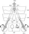
도 9a 내지 도 9c는, 본 개시의 일 실시 예에 따른, HMD(100)가 액티브 소자에 의해 가상 이미지(virtual image)의 초점을 제어하여 한쪽 눈의 원근 조절(visual accommodation/convergence)을 제어하는 것을 설명하기 위한 도면이다.Figures 9A-9C illustrate an embodiment of an
HMD(100)는 디스플레이에 표시되는 가상(virtual reality) 이미지의 초점을 지정된 시간에 가변할 수 있다.The
도 9a 내지 도 9c를 참조하면, 액티브 소자의 MEMS 미러의 옵티컬 파워를 시분할 구동하여, 각각의 3D입체 영상의 계층별(layer)(904-i) 초점을 조절할 수 있다.9A to 9C, the optical powers of the MEMS mirrors of the active elements may be time-division driven to adjust the focus of each 3D stereoscopic image layer 904-i.
그리고 HMD(100)는 영상인식 방법에 의해 디스플레이에 표시되는 가상 이미지에서 가상 이미지 내의 물체의 위치를 추정할 수 있다. 이때, HMD(100)는 추정된 물체의 위치를 바탕으로 액티브 소자를 이용하여 이미지의 초점을 가변하여 가상 이미지의 초점 거리를 조절할 수 있다. 그리고 HMD(100)는 사용자의 눈과 가상 이미지 내의 물체의 거리에 비례하여 액티브 소자의 파워를 가변시키면서 가상 이미지의 각 레이어별 초점을 조절할 수 있다.Then, the
예를 들어, 도 9a는, 사용자가 HMD(100)를 통해 물체의 거리가 눈으로부터 지정된 거리(904-i)에 있을 때의 가상 영상을 볼 때 액티브 소자(901)의 옵티컬 파워 조절을 설명하기 위한 도면이다. 예를 들어, 특정 거리(904-i)의 물체를 볼 때는 액티브 소자(901)를 구성하는 마이크로미러의 기울기(tilt)가 변화가 없다.For example, FIG. 9A illustrates the optical power adjustment of the
도 9b를 참조하면, 물체가 특정 거리(904-i)보다 눈에 가까운 가상 영상(904-n) 레이어가 존재할 때, 액티브 소자(901)의 MEMS 미러들은 각각의 이미지 내의 물체의 초점거리에 따라 기울기(tilt)가 변하며 +Diopter로 옵티컬 파워를 조절하게 된다.9B, when there is a virtual image 904-n layer in which an object is closer to the eye than a specific distance 904-i, the MEMS mirrors of the
도 9c를 참조하면, 물체가 특정 거리(904-i)보다 눈에서 먼 거리에 가상 영상(904-1) 레이어가 존재할 때, 액티브 소자(901)의 MEMS 미러들은 각각의 이미지 내의 물체의 초점거리에 따라 기울기(tilt)가 변하며 -Diopter 값으로 옵티컬 파워를 조절하게 된다.9C, when an object has a virtual image 904-1 layer at a distance greater than a specific distance 904-i, the MEMS mirrors of the
따라서, HMD(100)는 가상 영상을 볼 때, 사용자의 눈과 가상 이미지 안에 있는 물체의 거리를 지정된 값(예를 들어, 1m)으로 기준(threshold)을 설정할 수 있다. 설정된 기준에 따라, HMD(100)는 물체가 눈에서 1m보다 먼 거리에 있는 3D 레이어에서는 옵티컬 파워를 -Dipoter로 하여 초점 거리를 시분할로 가변시킬 수 있다. 또한, HMD(100)는 물체가 눈에서 1m 보다 가까운 거리에 있는 3D 레이어에서는 옵티컬 파워를 +Diopter로 하여 초점 거리를 시분할로 가변시킬 수 있다.Accordingly, when viewing the virtual image, the
이때, 3D 레이어가 기준 거리보다 멀리 있는 것은 근시를 교정하는 것과 같은 원리일 수 있다. 그리고, 3D 레이어가 기준 거리보다 너무 멀리 있는 경우 2D 영상을 보는 것과 같은 효과가 나타날 수 있다.At this time, the fact that the 3D layer is farther than the reference distance may be the same principle as correcting nearsightedness. If the 3D layer is too far from the reference distance, the same effect as viewing the 2D image can be obtained.
구체적으로 예를 들어, 3D 레이어의 수가 16개로 나누어지고, 1개의 3D 영상을 30Hz 단위로 만들 수 있다. 이때, 10KHz의 MEMS 디바이스일 때, 액티브 소자의 MEMS 미러는 30x16=480Hz로 구동하도록 구현할 수 있다.Specifically, for example, the number of 3D layers is divided into 16, and one 3D image can be formed in units of 30 Hz. At this time, when the MEMS device is 10 KHz, the MEMS mirror of the active device can be implemented to be driven at 30 x 16 = 480 Hz.
도 10a 및 도 10b는, HMD(100)가 액티브 소자에 의해 가상 이미지(virtual image)의 거리에 따른 두 눈의 원근조절(visual accommodation)및 시각적 수렴(visual convergence)을 설명하기 위한 도면이다.FIGS. 10A and 10B are views for explaining the visual accommodation and visual convergence of two eyes according to the distance of a virtual image by the active element of the
도 9a 내지 도 9c에서 상술한 바와 같이, HMD(100)는 액티브 소자의 MEMS 미러의 옵티컬 파워를 시분할 구동하여, 각각의 3D입체 영상의 계층별(layer) 초점을 조절할 수 있다.As described above with reference to FIGS. 9A to 9C, the
도 10a를 참조하면, HMD(100)는 두 눈(1000-1, 1000-2)의 원근 조절 및 시각적 수렴이 가상 이미지 안의 물체(1002, 1003) 중 원거리에 있는 물체(1003)에 맞춰져 눈의 피로를 개선시킬 수 있다.Referring to FIG. 10A, the
가상의 이미지(1001)는 물체(1002, 1003)을 포함하고 있다. HMD(100)는 영상인식 기술에 의해 디스플레이에 표시되는 가상 이미지 내의 물체의 위치를 추정할 수 있다. 즉, HMD(100)는 물체(1002, 1003) 중 사용자의 눈으로부터 근거리에 있는 물체(1002-1) 및 원거리에 있는 물체(1003-1)를 추정할 수 있다.The
이때, 물체(1002-1)가 눈에 가까운 가상 영상(1004) 레이어가 존재할 때, 도9b에서 설명한 바와 같이, 액티브 소자(901)의 MEMS 미러들은 이미지 내의 물체(1002-1)의 초점거리에 따라 기울기(tilt)가 변하며 +Diopter로 옵티컬 파워를 조절하게 된다. 그리고 사용자의 눈(1000-1)의 원근 조절 및 시각적 수렴은 근거리에 위치한 물체(1002-2)에 맞춰져 눈의 피로를 개선시킬 수 있다.9B, the MEMS mirrors of the
도 10b를 참조하면, HMD(100)는 두 눈(1000-1, 1000-2)의 원근 조절 및 시각적 수렴이 가상 이미지 안의 물체(1002, 1003) 중 근거리에 있는 물체(1002)에 맞춰져 눈의 피로를 개선할 수 있다.10B, the
가상의 이미지(1001)는 물체(1002, 1003)을 포함하고 있다. HMD(100)는 영상인식 기술에 의해 디스플레이에 표시되는 가상 이미지 내의 물체의 위치를 추정할 수 있다. 즉, HMD(100)는 물체(1002, 1003) 중 사용자의 눈으로부터 근거리에 있는 물체(1002-1) 및 원거리에 있는 물체(1003-1)를 추정할 수 있다.The
이때, 물체(1003-1)가 눈에서 먼 가상 영상(1005) 레이어에 존재할 때, 도9c에서 설명한 바와 같이, 액티브 소자(901)의 MEMS 미러들은 이미지 내의 물체(1003-1)의 초점거리에 따라 기울기(tilt)가 변하며 -Diopter로 옵티컬 파워를 조절하게 된다. 그리고 사용자의 눈(1000-1, 1000-2)의 원근 조절 및 시각적 수렴은 원거리에 위치한 물체(1003-2)에 맞춰져 눈의 피로를 개선시킬 수 있다.At this time, when the object 1003-1 exists in the
상술한 방법을 통하여, HMD(100)는 지정된 시간이 지날 때, 사용자의 초점을 가변하여 눈의 피로를 최소화할 수 있다. 즉, 사용자의 눈과 HMD(100) 영상의 초점 거리가 원거리인 상태에서 사용자가 지정된 시간 이상 영상을 시청할 때, HMD(100)는 이미지 내의 물체 중 초점 거리가 근거리에 위치한 물체로 사용자의 초점을 이동할 수 있다. 반면, 사용자의 눈과 HMD(100) 영상의 초점 거리가 근거리인 상태에서 사용자가 지정된 시간 이상 영상을 시청할 때, HMD(100)는 이미지 내의 물체 중 초점 거리가 원거리에 위치한 물체로 사용자의 초점을 이동할 수 있다.Through the above-described method, the
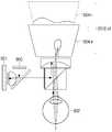
도 11은 본 개시의 일 실시예에 따른, 액티브 소자와 회절 소자를 이용한 증강 현실(augmented reality)를 위한 HMD의 구성도이다.11 is a block diagram of an HMD for augmented reality using an active element and a diffraction element, according to an embodiment of the present disclosure.
증강 현실(augmented reality)은 가상 이미지가 현실 세계의 물리적 환경 공간과 혼합될 수 있도록 하는 기술이다. 이때, 가상 현실과 실상 간의 초점이 불일치 되는 문제점이 발생할 수 있다.Augmented reality is a technology that allows a virtual image to be mixed with the physical environment space of the real world. At this time, there may arise a problem that the focus between the virtual reality and the actual image is inconsistent.
도 11을 참조하면, 디스플레이 스크린(1100)에서 방출한 X편광(X-polarization)은 렌즈(1106)를 통과하고 제1 회절소자(1103)을 투과하여 1/4파장판(quarter wave plate)(1107)을 통과하여 액티브 소자(1101)에 수렴한다. 이때, 렌즈(1106)는 X편광을 평행광으로 만드는 콜리메이팅(Collimating Lens)으로 구현할 수 있다.11, X-polarization emitted from the
이때, 제1 회절소자(1103)는 도광판(1105)의 내부에 있고, 액티브 소자(1101)와 평행하게 위치한다. 또한 제1 회절소자(1103)는 디스플레이(1100)에서 방출되는 제1 직선편광 상태인 X편광에 대해서는 투과시키고, 제1 직선편광과 수직인 제2 직선편광 상태인 Y편광에 대해서는 회절시킨다.At this time, the
액티브 소자(1101)는 마이크로미러의 회전운동과 병진운동에 의해 기울기를 조절한다. 액티브 소자(1101)의 가변 마스킹 패턴에 의해 사용자의 시력을 측정할 수 있다. 그리고 액티브 소자(1101)는 옵티컬 파워를 조절하여 사용자의 시력을 보정할 수 있다.The
액티브 소자(1101)은 1/4파장판(1107)에 의해 Y편광(Y-polarization)을 발산하고, 제1회절 소자(1103)에서 전반사하여 광의 각도를 변경한다. 이때, 제1 회절소자(1103) 및 제2 회절소자(1104)는 도광판(light guide)(1105) 내부에 있고, 도광판은 평면의 유리인 웨이브 가이드(waveguide)일 수 있다. 제1 회절소자(1103)에 의해 회절된 광선은 도광판(1105) 내부에서 전반사(1108)되어 제2 회절소자(1104)에서 회절된다. 제2 회절소자(1104)에서 회절된 광선은 사용자의 망막(1102)에 결상된다.The
이때, 동공 사출 축(pupil exit axis)에서 눈의 광축 Z축에 대해, 액티브 소자(1101)의 광축이 0도에서 +/-15도 근처에 배치될 수 있다. 이에 따라, 액티브 소자는 눈(1102) 앞의 시야를 가리지 않도록 측면에 배치하여 안경처럼 얇으면서 가상 및 실상 간의 초점 불일치를 개선하는 HMD(100)을 설계할 수 있다.At this time, with respect to the optical axis Z axis of the eye at the pupil exit axis, the optical axis of the
상술한 X편광 및 Y편광은 본 개시를 설명하기 위한 일 실시예일뿐, 이에 한정하지 아니하고 다양한 변형에 의해 구현될 수 있다.The X polarized light and Y polarized light described above are only examples for explaining the present disclosure, but can be implemented by various modifications without being limited thereto.
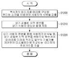
도 12는 본 개시의 일 실시 예에 따른, HMD(100)에서 액티브 소자를 이용하여 시력을 측정하고 보정하는 방법을 설명하기 위한 순서도이다.12 is a flowchart for explaining a method of measuring and correcting visual acuity using an active element in the
S1200 단계에서, HMD(100)는 복수개의 마이크로 미러로 구성된 액티브 소자를 이용하여 사용자의 시력을 검출할 수 있다. 시력을 검출하는 방법은 본 개시에서 상세히 설명하였으므로 여기에서는 생략하도록 한다.In operation S1200, the
S1210 단계에서, HMD(100)는 검출된 사용자의 시력 정보를 사용자의 생체 정보와 함께 저장할 수 있다. 예를 들어, 사용자의 생체 정보는 홍채 인식, 음성 인식, 얼굴 인식, 지문 인식 등 다양한 정보를 저장할 수 있다. 따라서, 사용자가 동일한 HMD(100)를 재사용할 때, HMD(100)는 사용자의 생체 정보를 바탕으로 자동으로 사용자의 시력 정보에 적합하도록 시력을 보정할 수 있다.In step S1210, the
S1220 단계에서, HMD(100)는 저장된 사용자 정보를 바탕으로 사용자가 인식될 때, 검출된 시력 정보를 바탕으로 복수 개의 마이크로 미러 중 적어도 일부의 기울기를 제어하여 디스플레이에 제공되는 이미지의 초점 거리를 조절할 수 있다. 초점 거리를 조절하는 방법은 본 개시에서 상술하였으므로 여기에서는 생략하도록 한다.In step S1220, when the user is recognized based on the stored user information, the
상술한 바와 같이, 본 개시의 실시예들에 따른 헤드 마운티드 디스플레이 장치는, 액티브 소자를 이용하여 사용자의 시력을 측정하고 사용자의 시력을 보정하여, 사용자에게 최적의 이미지를 제공할 수 있다. 또한, 헤드 마운티드 디스플레이 장치는 액티브 소자를 이용하여 소형화될 수 있으며, 사용자에게 고해상도의 디스플레이 화면을 제공할 수 있다.As described above, the head-mounted display device according to the embodiments of the present disclosure can measure the visual acuity of the user using the active element and correct the visual acuity of the user, thereby providing an optimal image to the user. In addition, the head-mounted display device can be miniaturized using an active element, and can provide a high-resolution display screen to the user.
또한, 상술한 제어 방법을 수행하기 위한 프로그램은 저장부(미도시) 이외에도 다양한 기록 매체에 저장되어 디스플레이 장치에 탑재될 수도 있다.In addition, the program for performing the control method described above may be stored in various recording media in addition to a storage unit (not shown), and may be mounted on a display device.
일 예로, 디스플레이 장치의 프로세서(미도시)를 통해 수행하는 프로그램이 저장된 비일시적 판독 가능 매체(non-transitory computer readable medium)가 제공될 수 있다.As an example, a non-transitory computer readable medium may be provided on which a program to be executed via a processor (not shown) of the display device is stored.
비일시적 판독 가능 매체란 레지스터, 캐쉬, 메모리 등과 같이 짧은 순간 동안 데이터를 저장하는 매체가 아니라 반영구적으로 데이터를 저장하며, 기기에 의해 판독(reading)이 가능한 매체를 의미한다. 구체적으로는, 상술한 다양한 어플리케이션 또는 프로그램들은 CD, DVD, 하드 디스크, 블루레이 디스크, USB, 메모리카드, ROM 등과 같은 비일시적 판독 가능 매체에 저장되어 제공될 수 있다.A non-transitory readable medium is a medium that stores data for a short period of time, such as a register, cache, memory, etc., but semi-permanently stores data and is readable by the apparatus. In particular, the various applications or programs described above may be stored on non-volatile readable media such as CD, DVD, hard disk, Blu-ray disk, USB, memory card, ROM,
또한, 이상에서는 본 발명의 바람직한 실시예에 대하여 도시하고 설명하였지만, 본 발명은 상술한 특정의 실시예에 한정되지 아니하며, 청구범위에서 청구하는 본 발명의 요지를 벗어남이 없이 당해 발명이 속하는 기술분야에서 통상의 지식을 가진자에 의해 다양한 변형실시가 가능한 것은 물론이고, 이러한 변형실시들은 본 발명의 기술적 사상이나 전망으로부터 개별적으로 이해되어서는 안될 것이다.While the present invention has been particularly shown and described with reference to exemplary embodiments thereof, it is to be understood that the invention is not limited to the disclosed exemplary embodiments, but, on the contrary, It should be understood that various modifications may be made by those skilled in the art without departing from the spirit and scope of the present invention.
100: 헤드마운티드 디스플레이(HMD)
210: 디스플레이
220: 프로세서
230: 메모리
240, 501, 720, 801, 901: 액티브소자
260: 광학부100: Head-mounted display (HMD)
210: Display
220: Processor
230: Memory
240, 501, 720, 801, 901: active element
260: Optical part
Claims (20)
Translated fromKorean이미지를 제공하는 디스플레이;
복수 개의 마이크로 미러로 구성되며 상기 디스플레이에 제공된 이미지를 반사하는 액티브 소자; 및
사용자의 시력을 검출하고, 상기 검출된 사용자의 시력에 기반하여 상기 복수의 마이크로 미러 중 적어도 일부의 기울기를 제어하여 상기 디스플레이에 제공된 이미지의 초점 거리를 조절하는 프로세서;를 포함하는 디스플레이 장치.A head mounted display apparatus comprising:
A display providing an image;
An active element formed of a plurality of micromirrors and reflecting an image provided on the display; And
And a processor for detecting a user's visual acuity and controlling a tilt of at least a portion of the plurality of micromirrors based on the detected visual acuity of the user to adjust a focal distance of an image provided on the display.
상기 프로세서는,
상기 디스플레이에서 방출하는 시력 측정을 위한 광선 중의 일부 영역만 사용자의 망막에 결상하도록 상기 액티브 소자에 마스크(mask) 패턴을 생성하고, 상기 액티브 소자의 옵티컬 파워를 가변하여 시력을 검출하는 디스플레이 장치.The method according to claim 1,
The processor comprising:
A mask pattern is generated in the active element so that only a part of the light rays for visual acuity measurement emitted from the display is imaged on the user's retina and the optical power of the active element is varied to detect visual acuity.
상기 프로세서는,
상기 검출된 시력을 바탕으로 상기 액티브 소자의 옵티컬 파워(optical power)를 조절하여 상기 사용자의 시력을 보정하는 디스플레이 장치.The method according to claim 1,
The processor comprising:
And adjusts the optical power of the active element based on the detected visual acuity to correct the visual acuity of the user.
상기 프로세서는,
상기 디스플레이에 표시되는 가상(Virtual Reality) 이미지의 초점을 지정된 시간에 가변하거나, 이미지 인식에 의해 상기 디스플레이에 표시되는 상기 가상 이미지의 물체의 위치를 추정하여 상기 이미지의 초점을 가변하여 상기 가상 이미지의 초점 거리를 가변하는 디스플레이 장치.The method according to claim 1,
The processor comprising:
A virtual reality image displayed on the display is changed in focus at a designated time or the position of an object of the virtual image displayed on the display is estimated by image recognition to vary the focus of the image, A display device for varying a focal distance.
상기 프로세서는,
가상 이미지의 물체의 거리에 비례하여 액티브 소자의 파워를 가변하여 상기 가상 이미지의 각 레이어별 초점을 조절하고,
상기 사용자가 근시일 때, 렌즈의 파워에 오프셋을 지정하여 상기 액티브 소자의 파워가 가변함에 따라 상기 사용자의 시력 조절 범위를 확대하는 디스플레이 장치.The method according to claim 1,
The processor comprising:
Adjusting a focus of each layer of the virtual image by varying the power of the active element in proportion to the distance of the object of the virtual image,
Wherein when the user is nearsightedness, an offset is assigned to the power of the lens to enlarge the user's visual acuity adjustment range as the power of the active element varies.
상기 프로세서는,
상기 디스플레이의 해상도를 증대할 수 있도록 상기 액티브 소자를 고속 틸팅(tilting) 구동하는 디스플레이 장치.The method according to claim 1,
The processor comprising:
Wherein the active element is driven at a high-speed tilting so as to increase the resolution of the display.
상기 액티브 소자는,
상기 디스플레이 및 광로와 수직방향으로 배치되는 디스플레이 장치.The method according to claim 1,
The active element includes:
And is disposed in a direction perpendicular to the display and the optical path.
상기 검출된 시력 정보 및 상기 사용자의 생체 정보를 저장하는 메모리;를 더 포함하는 디스플레이 장치.The method according to claim 1,
And a memory for storing the detected vision information and the biometric information of the user.
복수의 편광판;을 더 포함하고,
제1 편광판은 상기 액티브 소자 및 렌즈 사이 배치되고, 제2 편광판은 렌즈 미러와 상기 제2 편광 빔 스플리터의 앞면에 배치되며, 제3 편광판은 상기 제2 편광 판과 수직 배치되고 상기 액티브 소자와 평행하며 상기 제2 편광 빔 스플리터의 일 측면에 배치되어 가상의 이미지를 획득하는 디스플레이 장치.The method according to claim 1,
And a plurality of polarizing plates,
The first polarizing plate is disposed between the active element and the lens, the second polarizing plate is disposed on the front surface of the lens mirror and the second polarizing beam splitter, and the third polarizing plate is disposed perpendicular to the second polarizing plate and parallel to the active element And is disposed on one side of the second polarization beam splitter to obtain a virtual image.
상기 제1 편광판 및 상기 제2 편광판은 쿼터 웨이브 플레이트(quarter-wave plate)이고, 상기 제3 편광판은 하프 웨이브 플레이트(half wave plate)인 디스플레이 장치.10. The method of claim 9,
Wherein the first polarizing plate and the second polarizing plate are quarter-wave plates, and the third polarizing plate is a half wave plate.
상기 디스플레이에서 방출하는 광선을 평행광으로 만드는 콜리메이팅 렌즈(Collimating Lens);
상기 렌즈에서 방출한 광선을 수렴(convergence) 혹은 발산(Divergence)하여 반사하는 액티브 소자;
상기 액티브 소자에서 방출한 광선을 회절시키는 제1 회절소자;
상기 제1 회절소자와 상기 액티브 소자 사이에 배치하여 편광 상태를 바꾸는 쿼터 웨이브 파장판(Quarter Wave Plate);
상기 회절된 광선을 전반사에 의해 도광시키는 도광판(Light Guide); 및
상기 광선을 회절에 의해 사용자에게 방출하는 제2 회절소자;를 더 포함하는 디스플레이 장치.The method according to claim 1,
A collimating lens for collimating light emitted from the display;
An active element that converges or diverges the light beam emitted from the lens and reflects the light beam;
A first diffractive element for diffracting a light beam emitted from the active element;
A quarter wave plate disposed between the first diffraction element and the active element to change a polarization state thereof;
A light guide for guiding the diffracted light by total reflection; And
And a second diffractive element for diffracting the light beam to a user by diffraction.
상기 제1 회절소자는,
상기 디스플레이에서 방출되는 제1 직선편광 상태에 대해서는 투과시키고, 상기 제1 직선편광과 수직인 제2 직선편광 상태에 대해서는 회절시키는 디스플레이 장치.12. The method of claim 11,
Wherein the first diffractive element comprises:
And transmits the first linearly polarized light state emitted from the display and diffracts the second linearly polarized light state perpendicular to the first linearly polarized light.
상기 제1 회절 소자는 상기 액티브 소자와 평행하게 배치되고, 상기 제2 회절 소자는 상기 사용자의 눈과 평행하게 배치되며,
상기 사용자의 눈의 광축에 대해 상기 액티브 소자의 광축이 지정된 각도로 배치되어, 증강 현실(Augmented Reality)용 영상의 초점을 조절하는 디스플레이 장치.12. The method of claim 11,
Wherein the first diffractive element is disposed in parallel with the active element, the second diffractive element is disposed in parallel with the eye of the user,
Wherein an optical axis of the active element is arranged at a specified angle with respect to an optical axis of the user's eye to adjust a focus of an augmented reality image.
복수 개의 마이크로 미러로 구성된 액티브 소자를 이용하여 사용자의 시력 정보를 검출하는 단계;
상기 검출된 시력 정보를 상기 사용자 정보와 함께 저장하는 단계;
상기 사용자 정보를 통해 사용자가 인식되면, 상기 검출된 시력 정보를 바탕으로 복수의 마이크로 미러 중 적어도 일부의 기울기를 제어하여 디스플레이에 제공되는 이미지의 초점 거리를 조절하는 단계;를 포함하는 디스플레이 방법.A method of displaying a head mounted display apparatus,
Detecting visual information of a user using an active element including a plurality of micro mirrors;
Storing the detected vision information together with the user information;
Controlling a slope of at least a portion of the plurality of micromirrors based on the detected vision information to adjust a focal length of an image provided on the display when the user is recognized through the user information.
상기 검출하는 단계는,
디스플레이에서 방출하는 시력 측정을 위한 광선 중 일부 영역만 상기 액티브 소자의 중심부근에 맺히고, 상기 일부 영역이 상기 사용자의 망막에 결상하도록 마스크(mask) 패턴을 생성하여, 상기 액티브 소자의 옵티컬 파워를 가변하여 시력을 측정하는 디스플레이 방법.15. The method of claim 14,
Wherein the detecting comprises:
A mask pattern is formed so that only a part of the light rays for visual acuity measurement emitted from the display is formed in the vicinity of the center of the active element and the partial area is imaged on the retina of the user to change the optical power of the active element Thereby measuring visual acuity.
상기 액티브 소자에서 상기 검출된 시력을 바탕으로 상기 사용자의 옵티컬 파워(optical power)를 조절하여 상기 사용자의 시력을 보정하는 단계;를 더 포함하는 디스플레이 방법.15. The method of claim 14,
And adjusting the optical power of the user based on the detected visual acuity in the active device to correct the visual acuity of the user.
상기 초점거리를 조절하는 단계는,
디스플레이에 표시되는 가상(Virtual Reality) 이미지의 초점을 지정된 시간에 가변하거나, 이미지 인식에 의해 상기 디스플레이에 표시되는 상기 가상 이미지 내의 물체의 위치를 추정하여 상기 이미지의 초점을 가변하여 상기 가상 이미지의 초점 거리를 가변하는 단계;를 더 포함하는 디스플레이 방법.15. The method of claim 14,
Wherein adjusting the focal length comprises:
A virtual reality image displayed on the display is focused at a designated time, or the position of an object in the virtual image displayed on the display is estimated by image recognition to vary the focus of the image, And varying the distance.
상기 가상 이미지 내의 물체의 거리에 비례하여 액티브 소자의 파워를 가변하여 상기 가상 이미지의 각 레이어별 초점을 조절하는 단계;를 더 포함하는 디스플레이 방법.15. The method of claim 14,
And adjusting the focus of each layer of the virtual image by varying the power of the active device in proportion to the distance of the object in the virtual image.
사용자가 근시일 때, 렌즈의 파워에 오프셋을 지정하여 상기 액티브 소자의 파워가 가변함에 따라 상기 사용자의 시력 조절 범위를 확대하는 단계;를 더 포함하는 디스플레이 방법.19. The method of claim 18,
And enlarging the user's visual acuity adjustment range as the power of the active element is varied by designating an offset in power of the lens when the user is nearsighted.
디스플레이의 해상도를 증대할 수 있도록 상기 액티브 소자를 고속 틸팅(tilting) 구동하는 단계;를 더 포함하는 디스플레이 방법.15. The method of claim 14,
And driving the active element at a high tilting speed so as to increase the resolution of the display.
Priority Applications (7)
| Application Number | Priority Date | Filing Date | Title |
|---|---|---|---|
| TW105116945ATWI718151B (en) | 2015-06-15 | 2016-05-31 | Head mounted display apparatus and display method thereof |
| AU2016279665AAU2016279665B2 (en) | 2015-06-15 | 2016-06-02 | Head mounted display apparatus |
| PCT/KR2016/005827WO2016204433A1 (en) | 2015-06-15 | 2016-06-02 | Head mounted display apparatus |
| US15/178,978US10386638B2 (en) | 2015-06-15 | 2016-06-10 | Head mounted display apparatus |
| EP16174393.5AEP3106911B1 (en) | 2015-06-15 | 2016-06-14 | Head mounted display apparatus |
| CN201610424539.9ACN106249412B (en) | 2015-06-15 | 2016-06-15 | head mounted display device |
| US16/504,027US10656423B2 (en) | 2015-06-15 | 2019-07-05 | Head mounted display apparatus |
Applications Claiming Priority (2)
| Application Number | Priority Date | Filing Date | Title |
|---|---|---|---|
| US201562175627P | 2015-06-15 | 2015-06-15 | |
| US62/175,627 | 2015-06-15 |
Publications (1)
| Publication Number | Publication Date |
|---|---|
| KR20160147636Atrue KR20160147636A (en) | 2016-12-23 |
Family
ID=57736080
Family Applications (1)
| Application Number | Title | Priority Date | Filing Date |
|---|---|---|---|
| KR1020160006427AWithdrawnKR20160147636A (en) | 2015-06-15 | 2016-01-19 | Head Mounted Display Apparatus |
Country Status (4)
| Country | Link |
|---|---|
| US (1) | US10656423B2 (en) |
| KR (1) | KR20160147636A (en) |
| AU (1) | AU2016279665B2 (en) |
| TW (1) | TWI718151B (en) |
Cited By (13)
| Publication number | Priority date | Publication date | Assignee | Title |
|---|---|---|---|---|
| WO2019045174A1 (en)* | 2017-09-04 | 2019-03-07 | 주식회사 그루크리에이티브랩 | Method for providing location corrected image to hmd, method for displaying location corrected image on hmd, and hmd for displaying location corrected image using same |
| KR20190035574A (en)* | 2017-09-26 | 2019-04-03 | 주식회사 엘지화학 | Optical film, optical element and display device |
| KR20190064966A (en) | 2017-12-01 | 2019-06-11 | 김태경 | Image display optical apparatus and image generation method thereof |
| WO2019142953A1 (en)* | 2018-01-19 | 2019-07-25 | 전자부품연구원 | Foveated near-eye display system for resolving problem of vergence-accommodation conflict |
| KR20190116447A (en)* | 2017-02-23 | 2019-10-14 | 매직 립, 인코포레이티드 | Display system with variable power reflector |
| KR20200034401A (en)* | 2018-09-21 | 2020-03-31 | 삼성전자주식회사 | See-through type display apparatus including the same |
| US10788874B2 (en) | 2017-08-23 | 2020-09-29 | Samsung Electronics Co., Ltd. | Method and electronic device for controlling power between electronic devices |
| WO2020254555A1 (en)* | 2019-06-21 | 2020-12-24 | Eyesoft | Method for measuring the convergence of the eyes of a patient |
| US11256098B2 (en) | 2019-07-04 | 2022-02-22 | Samsung Electronics Co., Ltd. | Electronic device and method for displaying augmented reality |
| WO2022107962A1 (en)* | 2020-11-19 | 2022-05-27 | 주식회사 홀로랩 | System and operation method for holographic head-up display based on micromirror array element |
| US12245814B2 (en) | 2020-09-28 | 2025-03-11 | Hoya Lens Thailand Ltd. | Refraction measuring apparatus |
| US12279821B2 (en) | 2018-12-28 | 2025-04-22 | Hoya Lens Thailand Ltd. | Refractive property measurement device, measurement tool, and refractive property measurement method |
| WO2025159499A1 (en)* | 2024-01-23 | 2025-07-31 | 삼성전자 주식회사 | Lens and wearable electronic device comprising same |
Families Citing this family (26)
| Publication number | Priority date | Publication date | Assignee | Title |
|---|---|---|---|---|
| US20180144554A1 (en) | 2016-11-18 | 2018-05-24 | Eyedaptic, LLC | Systems for augmented reality visual aids and tools |
| CN108663803B (en)* | 2017-03-30 | 2021-03-26 | 腾讯科技(深圳)有限公司 | Virtual reality glasses, lens barrel adjusting method and device |
| US10401957B2 (en)* | 2017-04-06 | 2019-09-03 | Htc Corporation | System and method for providing simulated environment |
| US10609025B2 (en)* | 2017-04-06 | 2020-03-31 | Htc Corporation | System and method for providing simulated environment |
| US10546518B2 (en) | 2017-05-15 | 2020-01-28 | Google Llc | Near-eye display with extended effective eyebox via eye tracking |
| US10629105B2 (en) | 2017-06-15 | 2020-04-21 | Google Llc | Near-eye display with frame rendering based on reflected wavefront analysis for eye characterization |
| US20190012841A1 (en)* | 2017-07-09 | 2019-01-10 | Eyedaptic, Inc. | Artificial intelligence enhanced system for adaptive control driven ar/vr visual aids |
| US20190019448A1 (en)* | 2017-07-12 | 2019-01-17 | Oculus Vr, Llc | Redundant microleds of multiple rows for compensation of defective microled |
| US10984508B2 (en) | 2017-10-31 | 2021-04-20 | Eyedaptic, Inc. | Demonstration devices and methods for enhancement for low vision users and systems improvements |
| TWI677709B (en)* | 2018-01-09 | 2019-11-21 | 瑞軒科技股份有限公司 | Display device assembly |
| US11563885B2 (en) | 2018-03-06 | 2023-01-24 | Eyedaptic, Inc. | Adaptive system for autonomous machine learning and control in wearable augmented reality and virtual reality visual aids |
| US11187906B2 (en) | 2018-05-29 | 2021-11-30 | Eyedaptic, Inc. | Hybrid see through augmented reality systems and methods for low vision users |
| PE20211044A1 (en) | 2018-09-24 | 2021-06-03 | Ecolab Usa Inc | METHODS AND COMPOSITIONS FOR THE BENEFIT OF MINES PRIOR TO EXTRACTION |
| KR20210058964A (en) | 2018-09-24 | 2021-05-24 | 아이답틱 인코포레이티드 | Improved autonomous hands-free control in electronic visual aids |
| CN109164583A (en)* | 2018-11-07 | 2019-01-08 | 深圳珑璟光电技术有限公司 | A kind of underwater AR device |
| US11300776B2 (en)* | 2018-12-07 | 2022-04-12 | Beijing Voyager Technology Co., Ltd. | Coupled and synchronous mirror elements in a lidar-based micro-mirror array |
| US10880542B1 (en)* | 2018-12-19 | 2020-12-29 | Facebook Technologies, Llc | Near-eye optical element with embedded hot mirror |
| TWI765197B (en)* | 2019-03-29 | 2022-05-21 | 宏達國際電子股份有限公司 | Head-mounted device and strap structure thereof |
| US11662581B2 (en)* | 2019-11-13 | 2023-05-30 | Google Llc | Head mounted display with lightguide and holographic element |
| KR102244445B1 (en)* | 2019-11-22 | 2021-04-26 | 인하대학교 산학협력단 | Apparatus and method for occlusion capable near-eye display for augmented reality using single dmd |
| CN112987297B (en)* | 2019-12-17 | 2024-04-02 | 中强光电股份有限公司 | Light field near-eye display device and light field near-eye display method |
| CN114981703A (en) | 2020-01-22 | 2022-08-30 | 奇跃公司 | Double mirror scanning relay optics |
| EP4321923A4 (en) | 2021-08-05 | 2024-10-30 | Samsung Electronics Co., Ltd. | AUGMENTED REALITY DEVICE AND METHOD FOR DETECTING A USER'S GAZE |
| WO2023172266A1 (en)* | 2022-03-11 | 2023-09-14 | Hewlett-Packard Development Company, L.P. | Head-mountable display (hmd) virtual image distance adjustment based on eye tiredness of hmd wearer |
| TWI848397B (en)* | 2022-10-12 | 2024-07-11 | 中強光電股份有限公司 | Human eye vision measurement device and method for measuring the same |
| TWI850854B (en) | 2022-11-16 | 2024-08-01 | 宏碁股份有限公司 | Augmented reality display device |
Family Cites Families (32)
| Publication number | Priority date | Publication date | Assignee | Title |
|---|---|---|---|---|
| US5982343A (en) | 1903-11-29 | 1999-11-09 | Olympus Optical Co., Ltd. | Visual display apparatus |
| JP2893599B2 (en)* | 1989-10-05 | 1999-05-24 | セイコーエプソン株式会社 | Polarized light source and projection display |
| US4997269A (en) | 1990-02-28 | 1991-03-05 | The United States Of America As Represented By The Secretary Of The Navy | Scheiner-principle pocket optometer for self evaluation and bio-feedback accommodation training |
| JPH09127458A (en) | 1995-10-26 | 1997-05-16 | Matsushita Electric Works Ltd | On-head display with eyeball image measuring function |
| US5959780A (en) | 1996-04-15 | 1999-09-28 | Olympus Optical Co., Ltd. | Head-mounted display apparatus comprising a rotationally asymmetric surface |
| JP2000089157A (en) | 1998-09-11 | 2000-03-31 | Hiroshi Katagawa | Head mount display |
| DE19958436B4 (en) | 1999-12-03 | 2014-07-17 | Carl Zeiss Meditec Ag | Apparatus and method for active, physiologically evaluated, comprehensive correction of the aberrations of the human eye |
| DE10219512B4 (en) | 2002-04-30 | 2004-05-06 | Rodenstock Gmbh | Compensation for ametropia using a deformed / deformable mirror and / or corrective optics in a virtual reality display |
| JP2004038012A (en)* | 2002-07-05 | 2004-02-05 | Minolta Co Ltd | Image display device |
| KR20070021154A (en) | 2004-02-13 | 2007-02-22 | 스테레오 디스플레이, 인크. | 3D display using variable focusing lens |
| US7350922B2 (en)* | 2004-02-13 | 2008-04-01 | Angstrom, Inc. | Three-dimensional display using variable focal length micromirror array lens |
| US7418170B2 (en) | 2004-03-29 | 2008-08-26 | Sony Corporation | Optical device and virtual image display device |
| US6977777B1 (en)* | 2004-06-18 | 2005-12-20 | Sandia Corporation | Active optical zoom system |
| US7931373B2 (en) | 2004-12-03 | 2011-04-26 | The Invention Science Fund I, Llc | Vision modification with reflected image |
| US20060126181A1 (en) | 2004-12-13 | 2006-06-15 | Nokia Corporation | Method and system for beam expansion in a display device |
| US7486341B2 (en) | 2005-11-03 | 2009-02-03 | University Of Central Florida Research Foundation, Inc. | Head mounted display with eye accommodation having 3-D image producing system consisting of, for each eye, one single planar display screen, one single planar tunable focus LC micro-lens array, one single planar black mask and bias lens |
| US8643948B2 (en)* | 2007-04-22 | 2014-02-04 | Lumus Ltd. | Collimating optical device and system |
| JP5341462B2 (en) | 2008-10-14 | 2013-11-13 | キヤノン株式会社 | Aberration correction method, image processing apparatus, and image processing system |
| US20100169108A1 (en) | 2008-12-31 | 2010-07-01 | Microsoft Corporation | Distributed networks used for health-based data collection |
| JP5545076B2 (en) | 2009-07-22 | 2014-07-09 | ソニー株式会社 | Image display device and optical device |
| US20120013988A1 (en) | 2010-07-16 | 2012-01-19 | Hutchin Richard A | Head mounted display having a panoramic field of view |
| WO2012088478A1 (en) | 2010-12-24 | 2012-06-28 | Chunyu Gao | An ergonomic head mounted display device and optical system |
| US8934160B2 (en) | 2011-10-25 | 2015-01-13 | National Central University | Optical head-mounted display with mechanical one-dimensional scanner |
| US20130258486A1 (en)* | 2012-03-27 | 2013-10-03 | Dumitru Mihai Ionescu | Head-mount display |
| US8724206B2 (en) | 2012-09-28 | 2014-05-13 | Google Inc. | Photo-chromic coating for optics |
| US10335027B2 (en) | 2013-04-10 | 2019-07-02 | Eyenetra, Inc. | Methods and apparatus for assessment of refractive condition |
| US10228561B2 (en) | 2013-06-25 | 2019-03-12 | Microsoft Technology Licensing, Llc | Eye-tracking system using a freeform prism and gaze-detection light |
| WO2014209431A1 (en)* | 2013-06-27 | 2014-12-31 | Fusao Ishii | Wearable display |
| KR20150009852A (en) | 2013-07-17 | 2015-01-27 | 엘지전자 주식회사 | Method for displaying information using eyesight information and wearable device therefor |
| KR20150026336A (en)* | 2013-09-02 | 2015-03-11 | 엘지전자 주식회사 | Wearable display device and method of outputting content thereof |
| KR102160017B1 (en) | 2013-11-18 | 2020-09-25 | 한국전자통신연구원 | Glass appratus using eyesignt-based virtual screen |
| JP6566541B2 (en) | 2014-11-26 | 2019-08-28 | 株式会社トプコン | Ophthalmic equipment |
- 2016
- 2016-01-19KRKR1020160006427Apatent/KR20160147636A/ennot_activeWithdrawn
- 2016-05-31TWTW105116945Apatent/TWI718151B/ennot_activeIP Right Cessation
- 2016-06-02AUAU2016279665Apatent/AU2016279665B2/ennot_activeCeased
- 2019
- 2019-07-05USUS16/504,027patent/US10656423B2/ennot_activeExpired - Fee Related
Cited By (22)
| Publication number | Priority date | Publication date | Assignee | Title |
|---|---|---|---|---|
| US12271089B2 (en) | 2017-02-23 | 2025-04-08 | Magic Leap, Inc. | Variable-focus virtual image devices based on polarization conversion |
| US11982916B2 (en) | 2017-02-23 | 2024-05-14 | Magic Leap, Inc. | Variable-focus virtual image devices based on polarization conversion |
| KR20190116447A (en)* | 2017-02-23 | 2019-10-14 | 매직 립, 인코포레이티드 | Display system with variable power reflector |
| US10788874B2 (en) | 2017-08-23 | 2020-09-29 | Samsung Electronics Co., Ltd. | Method and electronic device for controlling power between electronic devices |
| US10445888B2 (en) | 2017-09-04 | 2019-10-15 | Grew Creative Lab Inc. | Method of providing position-corrected image to head-mounted display and method of displaying position-corrected image to head-mounted display, and head-mounted display for displaying the position-corrected image |
| WO2019045174A1 (en)* | 2017-09-04 | 2019-03-07 | 주식회사 그루크리에이티브랩 | Method for providing location corrected image to hmd, method for displaying location corrected image on hmd, and hmd for displaying location corrected image using same |
| US11366259B2 (en) | 2017-09-26 | 2022-06-21 | Lg Chem, Ltd. | Optical film, optical element, and imaging device |
| WO2019066429A1 (en)* | 2017-09-26 | 2019-04-04 | 주식회사 엘지화학 | Optical film, optical element, and imaging device |
| TWI685682B (en)* | 2017-09-26 | 2020-02-21 | 南韓商Lg化學股份有限公司 | Optical film, optical element and imaging device |
| KR20190035574A (en)* | 2017-09-26 | 2019-04-03 | 주식회사 엘지화학 | Optical film, optical element and display device |
| US11054649B2 (en) | 2017-12-01 | 2021-07-06 | Tae Kyung Kim | Image display optical apparatus and image generation method thereof |
| KR20190064966A (en) | 2017-12-01 | 2019-06-11 | 김태경 | Image display optical apparatus and image generation method thereof |
| WO2019142953A1 (en)* | 2018-01-19 | 2019-07-25 | 전자부품연구원 | Foveated near-eye display system for resolving problem of vergence-accommodation conflict |
| KR20200034401A (en)* | 2018-09-21 | 2020-03-31 | 삼성전자주식회사 | See-through type display apparatus including the same |
| US12044920B2 (en) | 2018-09-21 | 2024-07-23 | Samsung Electronics Co., Ltd. | See-through type display apparatus |
| US12279821B2 (en) | 2018-12-28 | 2025-04-22 | Hoya Lens Thailand Ltd. | Refractive property measurement device, measurement tool, and refractive property measurement method |
| WO2020254555A1 (en)* | 2019-06-21 | 2020-12-24 | Eyesoft | Method for measuring the convergence of the eyes of a patient |
| FR3097423A1 (en)* | 2019-06-21 | 2020-12-25 | Eyesoft | METHOD OF MEASURING THE CONVERGENCE OF THE EYES OF A PATIENT |
| US11256098B2 (en) | 2019-07-04 | 2022-02-22 | Samsung Electronics Co., Ltd. | Electronic device and method for displaying augmented reality |
| US12245814B2 (en) | 2020-09-28 | 2025-03-11 | Hoya Lens Thailand Ltd. | Refraction measuring apparatus |
| WO2022107962A1 (en)* | 2020-11-19 | 2022-05-27 | 주식회사 홀로랩 | System and operation method for holographic head-up display based on micromirror array element |
| WO2025159499A1 (en)* | 2024-01-23 | 2025-07-31 | 삼성전자 주식회사 | Lens and wearable electronic device comprising same |
Also Published As
| Publication number | Publication date |
|---|---|
| TWI718151B (en) | 2021-02-11 |
| US10656423B2 (en) | 2020-05-19 |
| US20190331922A1 (en) | 2019-10-31 |
| TW201643506A (en) | 2016-12-16 |
| AU2016279665B2 (en) | 2020-12-17 |
| AU2016279665A1 (en) | 2017-10-12 |
Similar Documents
| Publication | Publication Date | Title |
|---|---|---|
| US10656423B2 (en) | Head mounted display apparatus | |
| CN106249412B (en) | head mounted display device | |
| US11002898B2 (en) | Switchable reflective circular polarizer in head-mounted display | |
| US10712576B1 (en) | Pupil steering head-mounted display | |
| CN113302542B (en) | Angle-selective grating coupler for waveguide display | |
| US10012829B2 (en) | Systems, devices, and methods for wearable heads-up displays | |
| US10642048B2 (en) | Reflective circular polarizer for head-mounted display | |
| TWI688789B (en) | Virtual image generator and method to project a virtual image | |
| CN113302431A (en) | Volume Bragg grating for near-eye waveguide displays | |
| US8873149B2 (en) | Projection optical system for coupling image light to a near-eye display | |
| US11709358B2 (en) | Staircase in-coupling for waveguide display | |
| US11774758B2 (en) | Waveguide display with multiple monochromatic projectors | |
| US10809537B1 (en) | Varifocal waveguide display with dynamically bent waveguide | |
| CN107797290B (en) | Virtual reality display optical system and virtual reality glasses | |
| WO2019235059A1 (en) | Video projection system, video projection device, optical element for diffracting video display light, tool, and method for projecting video | |
| US20240168299A1 (en) | Kaleidoscopic waveguide as small-form-factor pupil expander | |
| US12282182B2 (en) | Reflector orientation of geometrical and mixed waveguide for reducing grating conspicuity for near-eye displays | |
| KR101893538B1 (en) | Optical control system and method for implementing retinal projection display according to change of pupil location | |
| KR20200063589A (en) | Multiple Focus Optical System and Head Mounted Display Using Thereof |
Legal Events
| Date | Code | Title | Description |
|---|---|---|---|
| PA0109 | Patent application | Patent event code:PA01091R01D Comment text:Patent Application Patent event date:20160119 | |
| PG1501 | Laying open of application | ||
| PC1203 | Withdrawal of no request for examination |