KR20160146776A - Kink-resistant guidewire with improved rigidity - Google Patents
Kink-resistant guidewire with improved rigidityDownload PDFInfo
- Publication number
- KR20160146776A KR20160146776AKR1020167030694AKR20167030694AKR20160146776AKR 20160146776 AKR20160146776 AKR 20160146776AKR 1020167030694 AKR1020167030694 AKR 1020167030694AKR 20167030694 AKR20167030694 AKR 20167030694AKR 20160146776 AKR20160146776 AKR 20160146776A
- Authority
- KR
- South Korea
- Prior art keywords
- guide wire
- core
- ribs
- cap
- diameter
- Prior art date
- Legal status (The legal status is an assumption and is not a legal conclusion. Google has not performed a legal analysis and makes no representation as to the accuracy of the status listed.)
- Granted
Links
- 238000000034methodMethods0.000claimsabstractdescription48
- 238000004519manufacturing processMethods0.000claimsabstractdescription9
- 239000011162core materialSubstances0.000claimsdescription180
- 238000000576coating methodMethods0.000claimsdescription16
- 239000011248coating agentSubstances0.000claimsdescription14
- 230000007704transitionEffects0.000claimsdescription7
- 210000000626ureterAnatomy0.000claimsdescription7
- 238000003754machiningMethods0.000claimsdescription6
- 210000004204blood vesselAnatomy0.000claimsdescription5
- 210000003708urethraAnatomy0.000claimsdescription4
- 230000015572biosynthetic processEffects0.000abstractdescription2
- 239000000463materialSubstances0.000description31
- 238000000227grindingMethods0.000description13
- 238000000429assemblyMethods0.000description9
- 230000000712assemblyEffects0.000description9
- 230000008569processEffects0.000description6
- 239000010935stainless steelSubstances0.000description5
- 229910001220stainless steelInorganic materials0.000description5
- 208000027418Wounds and injuryDiseases0.000description4
- 238000005452bendingMethods0.000description4
- 239000004033plasticSubstances0.000description4
- 229920003023plasticPolymers0.000description4
- 230000000472traumatic effectEffects0.000description4
- 210000001635urinary tractAnatomy0.000description4
- 230000009286beneficial effectEffects0.000description3
- 230000006378damageEffects0.000description3
- 230000002209hydrophobic effectEffects0.000description3
- 208000014674injuryDiseases0.000description3
- 210000003734kidneyAnatomy0.000description3
- 230000004048modificationEffects0.000description3
- 238000012986modificationMethods0.000description3
- 238000000465mouldingMethods0.000description3
- -1polyethylenePolymers0.000description3
- 238000001356surgical procedureMethods0.000description3
- 239000004698PolyethyleneSubstances0.000description2
- 230000009471actionEffects0.000description2
- 230000008901benefitEffects0.000description2
- 239000002131composite materialSubstances0.000description2
- 229920000295expanded polytetrafluoroethylenePolymers0.000description2
- 239000003365glass fiberSubstances0.000description2
- 239000004816latexSubstances0.000description2
- 229920000126latexPolymers0.000description2
- 230000001050lubricating effectEffects0.000description2
- 229910001000nickel titaniumInorganic materials0.000description2
- BASFCYQUMIYNBI-UHFFFAOYSA-NplatinumChemical compound[Pt]BASFCYQUMIYNBI-UHFFFAOYSA-N0.000description2
- 229920000573polyethylenePolymers0.000description2
- 229920001343polytetrafluoroethylenePolymers0.000description2
- 239000004810polytetrafluoroethyleneSubstances0.000description2
- 230000002792vascularEffects0.000description2
- 210000005166vasculatureAnatomy0.000description2
- 238000003466weldingMethods0.000description2
- 2380000101463D printingMethods0.000description1
- 229920000049Carbon (fiber)Polymers0.000description1
- 241000237074CentrisSpecies0.000description1
- 206010053567CoagulopathiesDiseases0.000description1
- VGGSQFUCUMXWEO-UHFFFAOYSA-NEtheneChemical compoundC=CVGGSQFUCUMXWEO-UHFFFAOYSA-N0.000description1
- HTTJABKRGRZYRN-UHFFFAOYSA-NHeparinChemical compoundOC1C(NC(=O)C)C(O)OC(COS(O)(=O)=O)C1OC1C(OS(O)(=O)=O)C(O)C(OC2C(C(OS(O)(=O)=O)C(OC3C(C(O)C(O)C(O3)C(O)=O)OS(O)(=O)=O)C(CO)O2)NS(O)(=O)=O)C(C(O)=O)O1HTTJABKRGRZYRN-UHFFFAOYSA-N0.000description1
- RTAQQCXQSZGOHL-UHFFFAOYSA-NTitaniumChemical compound[Ti]RTAQQCXQSZGOHL-UHFFFAOYSA-N0.000description1
- 239000000853adhesiveSubstances0.000description1
- 230000001070adhesive effectEffects0.000description1
- 230000002668anti-heparin effectEffects0.000description1
- 230000002965anti-thrombogenic effectEffects0.000description1
- 238000013459approachMethods0.000description1
- 239000004917carbon fiberSubstances0.000description1
- 230000008859changeEffects0.000description1
- 230000035602clottingEffects0.000description1
- 238000005520cutting processMethods0.000description1
- 238000003618dip coatingMethods0.000description1
- 230000000694effectsEffects0.000description1
- 230000007831electrophysiologyEffects0.000description1
- 238000002001electrophysiologyMethods0.000description1
- 238000005530etchingMethods0.000description1
- 238000001125extrusionMethods0.000description1
- 230000006870functionEffects0.000description1
- 210000001035gastrointestinal tractAnatomy0.000description1
- PCHJSUWPFVWCPO-UHFFFAOYSA-NgoldChemical compound[Au]PCHJSUWPFVWCPO-UHFFFAOYSA-N0.000description1
- 239000010931goldSubstances0.000description1
- 229910052737goldInorganic materials0.000description1
- 229960002897heparinDrugs0.000description1
- 229920000669heparinPolymers0.000description1
- 229920001903high density polyethylenePolymers0.000description1
- 239000004700high-density polyethyleneSubstances0.000description1
- 230000002401inhibitory effectEffects0.000description1
- 238000001746injection mouldingMethods0.000description1
- 238000003698laser cuttingMethods0.000description1
- 238000010329laser etchingMethods0.000description1
- 229920001684low density polyethylenePolymers0.000description1
- 239000004702low-density polyethyleneSubstances0.000description1
- 229910052751metalInorganic materials0.000description1
- 239000002184metalSubstances0.000description1
- 150000002739metalsChemical class0.000description1
- HLXZNVUGXRDIFK-UHFFFAOYSA-Nnickel titaniumChemical compound[Ti].[Ti].[Ti].[Ti].[Ti].[Ti].[Ti].[Ti].[Ti].[Ti].[Ti].[Ni].[Ni].[Ni].[Ni].[Ni].[Ni].[Ni].[Ni].[Ni].[Ni].[Ni].[Ni].[Ni].[Ni]HLXZNVUGXRDIFK-UHFFFAOYSA-N0.000description1
- 238000000059patterningMethods0.000description1
- 210000005259peripheral bloodAnatomy0.000description1
- 239000011886peripheral bloodSubstances0.000description1
- 229910052697platinumInorganic materials0.000description1
- 229920000642polymerPolymers0.000description1
- 229920001296polysiloxanePolymers0.000description1
- 230000004044responseEffects0.000description1
- 239000012781shape memory materialSubstances0.000description1
- 229910001285shape-memory alloyInorganic materials0.000description1
- 238000005507sprayingMethods0.000description1
- 239000007858starting materialSubstances0.000description1
- 239000000126substanceSubstances0.000description1
- 239000010936titaniumSubstances0.000description1
- 229910052719titaniumInorganic materials0.000description1
- 230000001052transient effectEffects0.000description1
- WFKWXMTUELFFGS-UHFFFAOYSA-NtungstenChemical compound[W]WFKWXMTUELFFGS-UHFFFAOYSA-N0.000description1
- 229910052721tungstenInorganic materials0.000description1
- 239000010937tungstenSubstances0.000description1
- 210000003462veinAnatomy0.000description1
Images


Classifications
- A—HUMAN NECESSITIES
- A61—MEDICAL OR VETERINARY SCIENCE; HYGIENE
- A61M—DEVICES FOR INTRODUCING MEDIA INTO, OR ONTO, THE BODY; DEVICES FOR TRANSDUCING BODY MEDIA OR FOR TAKING MEDIA FROM THE BODY; DEVICES FOR PRODUCING OR ENDING SLEEP OR STUPOR
- A61M25/00—Catheters; Hollow probes
- A61M25/01—Introducing, guiding, advancing, emplacing or holding catheters
- A61M25/09—Guide wires
- A61M2025/09058—Basic structures of guide wires
- A61M2025/09075—Basic structures of guide wires having a core without a coil possibly combined with a sheath
- A—HUMAN NECESSITIES
- A61—MEDICAL OR VETERINARY SCIENCE; HYGIENE
- A61M—DEVICES FOR INTRODUCING MEDIA INTO, OR ONTO, THE BODY; DEVICES FOR TRANSDUCING BODY MEDIA OR FOR TAKING MEDIA FROM THE BODY; DEVICES FOR PRODUCING OR ENDING SLEEP OR STUPOR
- A61M25/00—Catheters; Hollow probes
- A61M25/01—Introducing, guiding, advancing, emplacing or holding catheters
- A61M25/09—Guide wires
- A61M2025/09108—Methods for making a guide wire
- A—HUMAN NECESSITIES
- A61—MEDICAL OR VETERINARY SCIENCE; HYGIENE
- A61M—DEVICES FOR INTRODUCING MEDIA INTO, OR ONTO, THE BODY; DEVICES FOR TRANSDUCING BODY MEDIA OR FOR TAKING MEDIA FROM THE BODY; DEVICES FOR PRODUCING OR ENDING SLEEP OR STUPOR
- A61M25/00—Catheters; Hollow probes
- A61M25/01—Introducing, guiding, advancing, emplacing or holding catheters
- A61M25/09—Guide wires
- A61M2025/09116—Design of handles or shafts or gripping surfaces thereof for manipulating guide wires
- A—HUMAN NECESSITIES
- A61—MEDICAL OR VETERINARY SCIENCE; HYGIENE
- A61M—DEVICES FOR INTRODUCING MEDIA INTO, OR ONTO, THE BODY; DEVICES FOR TRANSDUCING BODY MEDIA OR FOR TAKING MEDIA FROM THE BODY; DEVICES FOR PRODUCING OR ENDING SLEEP OR STUPOR
- A61M25/00—Catheters; Hollow probes
- A61M25/01—Introducing, guiding, advancing, emplacing or holding catheters
- A61M25/09—Guide wires
- A61M2025/09175—Guide wires having specific characteristics at the distal tip
- A—HUMAN NECESSITIES
- A61—MEDICAL OR VETERINARY SCIENCE; HYGIENE
- A61M—DEVICES FOR INTRODUCING MEDIA INTO, OR ONTO, THE BODY; DEVICES FOR TRANSDUCING BODY MEDIA OR FOR TAKING MEDIA FROM THE BODY; DEVICES FOR PRODUCING OR ENDING SLEEP OR STUPOR
- A61M25/00—Catheters; Hollow probes
- A61M25/01—Introducing, guiding, advancing, emplacing or holding catheters
- A61M25/09—Guide wires
- A61M2025/09191—Guide wires made of twisted wires
- A—HUMAN NECESSITIES
- A61—MEDICAL OR VETERINARY SCIENCE; HYGIENE
- A61M—DEVICES FOR INTRODUCING MEDIA INTO, OR ONTO, THE BODY; DEVICES FOR TRANSDUCING BODY MEDIA OR FOR TAKING MEDIA FROM THE BODY; DEVICES FOR PRODUCING OR ENDING SLEEP OR STUPOR
- A61M2210/00—Anatomical parts of the body
- A61M2210/10—Trunk
- A61M2210/1078—Urinary tract
- A61M2210/1085—Bladder
- A—HUMAN NECESSITIES
- A61—MEDICAL OR VETERINARY SCIENCE; HYGIENE
- A61M—DEVICES FOR INTRODUCING MEDIA INTO, OR ONTO, THE BODY; DEVICES FOR TRANSDUCING BODY MEDIA OR FOR TAKING MEDIA FROM THE BODY; DEVICES FOR PRODUCING OR ENDING SLEEP OR STUPOR
- A61M2210/00—Anatomical parts of the body
- A61M2210/10—Trunk
- A61M2210/1078—Urinary tract
- A61M2210/1089—Urethra
Landscapes
- Health & Medical Sciences (AREA)
- Life Sciences & Earth Sciences (AREA)
- Biophysics (AREA)
- Pulmonology (AREA)
- Engineering & Computer Science (AREA)
- Anesthesiology (AREA)
- Biomedical Technology (AREA)
- Heart & Thoracic Surgery (AREA)
- Hematology (AREA)
- Animal Behavior & Ethology (AREA)
- General Health & Medical Sciences (AREA)
- Public Health (AREA)
- Veterinary Medicine (AREA)
- Media Introduction/Drainage Providing Device (AREA)
- Materials For Medical Uses (AREA)
Abstract
Translated fromKoreanDescription
Translated fromKorean우선권preference
본 출원은 본 출원에 전체적으로 참고로 포함되는, 2014년 4월 29일자로 출원된 미국 가출원 제61/985,887호의 우선권 이익을 주장한다.This application claims the benefit of US Provisional Application No. 61 / 985,887, filed April 29, 2014, which is incorporated herein by reference in its entirety.
본 출원은 가요성, 뒤틀림-저항성(kink-resistant) 가이드(guide) 또는 가이드와이어(guidewire)를 포함하는, 의료 시술에 사용하기 위한 가이드 또는 가이드와이어를 논의한다.The present application discusses a guide or guide wire for use in medical procedures, including a flexible, kink-resistant guide or guidewire.
긴(elongate) 가요성 가이드와이어가 대수술 없이 신체 내의 특정 내부 부위에 접근하기 위해 의료 시술에 사용될 수 있다. 가이드와이어는 신체를 통해, 예를 들어 말초 혈관, 위장관, 또는 요로를 통해 전진될 수 있다. 가이드와이어는 여러 분야 중에서 특히 심장학, 전기생리학, 위장병학, 비뇨기학, 및 방사선학에 사용될 수 있다.Elongate flexible guidewires can be used in medical procedures to access certain internal parts of the body without major surgery. The guide wire may be advanced through the body, e.g., through peripheral blood vessels, the gastrointestinal tract, or the urinary tract. Guidewires can be used in a variety of fields, particularly in cardiology, electrophysiology, gastroenterology, urology, and radiology.
일단 유치되어(indwelling) 위치되면, 가이드와이어는 카테터(catheter) 및/또는 다른 의료 기구의 원하는 부위로의 도입을 위한 경로를 한정하지만; 그러한 기구는 가이드와이어보다 덜 다루기 용이할 수 있고, 상당히 더 큰 질량을 가질 수 있으며, 그것들이 가이드와이어를 통해 전진될 때 가이드와이어를 구부러지게 할 위험을 야기할 수 있다.Once positioned indwelling, the guide wire defines a path for introduction to a desired site of a catheter and / or other medical device; Such a device may be less tractable than a guide wire, may have a significantly larger mass, and may pose a risk of bending the guide wire as they are advanced through the guide wire.
또한, 친수성(hydrophilic) 또는 윤활성(lubricious) 가이드와이어는 사용하기 어려울 수 있는데, 왜냐하면 그것들이 환자의 신체 내의 원하는 위치로부터 너무 쉽게 이동하거나 미끄러질 수 있기 때문이다. 또한, 플라스틱 또는 라텍스 장갑을 착용한 임상의가 친수성 또는 윤활성 가이드와이어를 적절하게 파지하고 조작하지 못할 수 있다.In addition, hydrophilic or lubricious guide wires can be difficult to use because they can move or slide too easily from the desired location in the patient ' s body. Also, clinicians wearing plastic or latex gloves may not be able to properly grasp and manipulate the hydrophilic or lubricous guide wire.
가이드와이어는 중심 코어(central core) 또는 코어 와이어 및 가이드와이어의 원위 부분을 따른 또는 코어를 둘러싸는 코일로 구성될 수 있다. 일반적으로, 코어의 치수 또는 크기가 본질적으로 그의 길이를 따라 가이드와이어의 강직성(stiffness)을 한정한다. 주어진 코어 재료에 대해, 그의 단면이 클수록, 전체 가이드와이어의 강직성이 커진다. 코어 와이어 재료의 선택이 가이드와이어의 성능 특성에 영향을 미치고, 그의 비용에 영향을 미친다. 또한, 외측 코일을 사용하는 것은 코일 내부의 코어 와이어의 직경이 코일 내부에 맞도록 그리고 너무 크지 않은 전체 외경을 가진 가이드와이어를 생성하도록 감소되거나 보다 작을 것을 요구한다. 스테인리스 강 코어 가이드와이어가 저렴할 수 있지만, 감소되거나 작은 직경에 의해, 그것을 통해 카테터 및/또는 다른 기구를 전진시키는 동안에 구부러지기 쉬울 수 있다. 유리섬유 복합재로 제조되는 코어가 구부러짐에 더욱 저항성일 수 있지만, 그것들은 갑자기 스냅핑(snapping)되기 더욱 쉬울 수 있고, 파편화(splintering)없이, 원위 단부의 가요성을 증가시키기 위해, 유리섬유 코어의 원위 단부에 테이퍼(taper)를 제공하는 것이 어렵다. 가이드와이어가 충분히 강직성이거나 강성이 아닌 경우, 구부러지기 더욱 쉬울 수 있고, 신체 내의 원하는 위치로 조종하고 지향시키는 것이 더욱 어려울 수 있다.The guide wire may comprise a central core or core wire and a coil along the distal portion of the guide wire or surrounding the core. Generally, the size or size of the core essentially defines the stiffness of the guide wire along its length. For a given core material, the greater the cross section thereof, the greater the rigidity of the entire guide wire. The choice of core wire material influences the performance characteristics of the guide wire and affects its cost. In addition, the use of an outer coil requires that the diameter of the core wire within the coil be reduced or smaller to fit within the coil and to produce a guide wire with a total outer diameter that is not too large. The stainless steel core guidewire may be inexpensive, but may be susceptible to bending while it is advancing the catheter and / or other instrumentation therethrough, by reduced or smaller diameter. Although the cores made of glass fiber composites may be more resistant to bending, they may be more susceptible to sudden snapping, and to increase the flexibility of the distal end without splintering, It is difficult to provide a taper at the distal end. If the guide wire is not sufficiently rigid or rigid, it may be easier to bend and it may be more difficult to steer and direct the desired position within the body.
더욱 우수한 조종성(maneuverability)을 위해 비교적 높은 정도의 강직성을 유지시키고 이로운 외측 마찰 또는 텍스처(texture) 특성을 갖는 가이드와이어가 필요하다.For better maneuverability, there is a need for a guide wire that maintains a relatively high degree of rigidity and has beneficial outer friction or texture properties.
가이드와이어를 사용하는 의료 시술을 포함하는 의료 처치에 사용하기 위한 장치, 구성요소, 조립체, 시스템, 방법 등의 실시예 및 그에 대한 향상이 본 명세서에 기술된다.Embodiments of devices, components, assemblies, systems, methods, and the like for use in medical procedures, including medical procedures using guidewires, and improvements thereto are described herein.
가이드와이어(용어 "가이드와이어"는 가이드, 가이드와이어, 및 유사한 장치를 지칭하는 데 사용됨)는 근위 단부, 원위 단부, 및 코어를 포함할 수 있다. 가이드와이어의 일부분, 예컨대 코어는 그의 전부 또는 일부분, 예컨대 근위 부분을 따라 하나 이상의 사전형성된 리브(rib)들을 포함할 수 있다. 가이드와이어의 일부분, 예컨대 코어는 감소된 직경(reduced diameter)의 영역 또는 단부를 포함할 수 있다. 예를 들어, 가이드와이어의 원위 영역이 테이퍼지거나 달리 감소된 직경을 가질 수 있다. 가이드와이어의 감소된 직경의 영역은 그 상에 캡(cap) 또는 슬리브(sleeve)를 포함할 수 있다. 캡 또는 슬리브는 가이드와이어의 완전한 직경(full diameter)의 영역 또는 가이드와이어를 통해 연장되는 사전형성된 리브들을 갖는 가이드와이어의 영역의 외경과 동일하거나 유사한(예컨대, ±0.1 인치) 외경을 생성하기 위해 감소된 직경의 영역 위에 끼워맞추어지도록 형상화/구성될 수 있다. 코어는 사전형성된 리브들 위를 포함하는, 그의 일부분 또는 전체 위에 외측 중합체 코팅을 포함할 수 있다.The guidewire (the term "guidewire" is used to refer to a guide, guidewire, and similar device) may include a proximal end, a distal end, and a core. A portion of the guide wire, e.g., a core, may include one or more preformed ribs along all or a portion thereof, e.g., a proximal portion. A portion of the guide wire, e.g., the core, may include an area or end of a reduced diameter. For example, the distal region of the guide wire may have a tapered or otherwise reduced diameter. The reduced diameter region of the guide wire may include a cap or sleeve on it. The cap or sleeve may be reduced to produce an outer diameter equal or similar (e.g., +/- 0.1 inches) to the outer diameter of the area of the full diameter of the guide wire or the area of the guide wire having preformed ribs extending through the guide wire. Lt; RTI ID = 0.0 > and / or < / RTI > The core may include an outer polymer coating over a portion or an entire portion thereof, including over preformed ribs.
일 실시예에서, 가이드와이어는 코어를 포함한다. 코어는 코어의 제1 부분을 따라 형성되는 리브들을 포함할 수 있으며, 코어의 제1 부분은 제1 직경을 갖고, 리브들은 가이드와이어의 외측 표면의 마찰을 증가시킨다. 리브들은 제1 부분을 따라 하나 이상의 나선형 코일들의 형상으로 배열될 수 있다. 본 명세서의 다른 곳에 기술된 바와 같은 다른 형상/구성이 또한 사용될 수 있다. 코어는 또한 제1 직경보다 작은 제2 직경을 갖는, 제1 부분의 원위에 있는 감소된 직경의 영역을 포함할 수 있다. 가이드와이어는 또한 제1 직경과 동일하거나 유사한 직경을 갖는 캡을 포함할 수 있으며, 캡은 캡의 에지가 제1 부분에 맞닿도록 코어의 감소된 직경의 영역 위에 위치된다. 캡은 매끄러운, 균일한 외측 표면을 가질 수 있다. 코어의 감소된 직경의 영역은 코어의 제1 부분에 인접한 채널을 포함할 수 있으며, 채널은 스냅-끼워맞춤(snap-fit) 또는 나사식 연결(threaded connection)로 캡의 일부분과 맞물리도록 형상화될 수 있다. 가이드와이어는 코어의 제1 부분 상에 코팅을 포함할 수 있다. 코팅은 캡에 걸쳐 연장되고, 코어의 제1 부분과 캡 사이의 매끄러운, 중단되지 않는 외측 표면 전이부(transition)를 형성할 수 있다.In one embodiment, the guidewire comprises a core. The core may comprise ribs formed along a first portion of the core, wherein the first portion of the core has a first diameter and the ribs increase friction of the outer surface of the guide wire. The ribs may be arranged in the shape of one or more helical coils along the first portion. Other shapes / configurations as described elsewhere herein may also be used. The core may also include a region of reduced diameter over the circle of the first portion, having a second diameter less than the first diameter. The guide wire may also include a cap having a diameter equal to or similar to the first diameter and the cap is positioned over a reduced diameter region of the core such that the edge of the cap abuts the first portion. The cap may have a smooth, uniform outer surface. The region of reduced diameter of the core may include a channel adjacent the first portion of the core and the channel may be shaped to engage a portion of the cap with a snap-fit or threaded connection . The guide wire may include a coating on the first portion of the core. The coating extends over the cap and can form smooth, uninterrupted outer surface transition between the cap and the cap.
의료 처치의 또는 가이드와이어를 사용하는 방법은 가이드와이어를 획득하는 단계를 포함할 수 있으며, 가이드와이어는 코어를 포함하고, 코어는 제1 직경을 갖는 코어의 제1 부분의 외측 표면을 따라 형성되는 리브들을 가지며, 리브들은 가이드와이어의 표면 마찰을 증가시킨다. 방법은 가이드와이어의 원위 단부를 환자의 신체의 혈관 내로 삽입하는 단계를 포함할 수 있다. 방법은 또한 가이드와이어를 환자의 신체 내의 원하는 위치로 조종하는 단계를 포함할 수 있다. 가이드와이어를 원하는 위치로 조종하는 단계는 가이드와이어를 요도 및 방광을 통해 환자의 신체의 요관 내로 조종하는 단계를 포함할 수 있다. 가이드와이어는 환자의 신장으로 또는 그 부근으로 조종될 수 있다. 리브들은 가이드와이어를 환자의 신체 내의 원하는 위치에 유지시켜 가이드와이어가 원하는 위치로부터 이동할 위험을 감소시키는 데 도움을 줄 수 있다. 가이드와이어를 획득하는 단계는 코어가 제1 직경보다 작은 제2 직경을 갖는, 제1 부분의 원위에 있는 감소된 직경의 영역을 추가로 포함하는 가이드와이어를 획득하는 단계를 추가로 포함할 수 있다. 가이드와이어를 획득하는 단계는 또한 제1 직경과 동일하거나 유사한 직경을 가진 캡을 갖는 가이드와이어를 획득하는 단계를 포함할 수 있으며, 캡은 캡의 에지가 제1 부분에 맞닿도록 코어의 감소된 직경의 영역 위에 위치된다.A method of using a medical treatment or using a guidewire may include acquiring a guidewire wherein the guidewire comprises a core and the core is formed along an outer surface of a first portion of the core having a first diameter Ribs, and the ribs increase the surface friction of the guide wire. The method may include inserting the distal end of the guidewire into a blood vessel of a patient's body. The method may also include the step of manipulating the guide wire to a desired position within the patient ' s body. The step of manipulating the guide wire to the desired position may include manipulating the guide wire through the urethra and bladder into the ureter of the patient's body. The guide wire may be steered to or near the patient's kidney. The ribs can help keep the guide wire in a desired position within the patient's body to reduce the risk of the guide wire moving away from the desired location. The step of acquiring the guide wire may further comprise acquiring a guide wire further comprising a region of reduced diameter on the circle of the first portion, the core having a second diameter smaller than the first diameter . Obtaining the guide wire may also include obtaining a guide wire having a cap having a diameter equal to or similar to the first diameter, the cap having a reduced diameter of the core Lt; / RTI >
가이드와이어를 제조하는 방법은 제1 단부 및 제2 단부를 갖는 긴 가이드와이어 코어 재료(예컨대, 코어 내에 형성되는 것으로 본 명세서의 다른 곳에 기술된 초기 재료와 유사할 수 있음)를 획득하는 단계, 및 긴 가이드와이어 코어 재료의 표면 상에 하나 이상의 리브들을 형성하는 단계를 포함할 수 있으며, 리브들은 가이드와이어의 외측 표면 상에 가시적인 패턴을 형성한다. 하나 이상의 리브들을 형성하는 단계는 제1 단부가 고정되어 유지되거나 반대 방향으로 비틀리는 상태에서 제2 단부를 긴 가이드와이어 코어 재료의 종축을 중심으로 비틀어 달성될 수 있다. 그러한 작업은 긴 가이드와이어 코어 재료를 그 상에 리브를 갖도록 소성 변형시킬 수 있다. 소성 변형은 변형 및/또는 리브들을 재료 내에 자연적으로 형성시킬 수 있거나 변형 및/또는 리브들을 재료 내에 형성시키도록 처리(예컨대, 열 처리)될 수 있다. 선택적으로, 하나 이상의 리브들을 형성하는 단계는 리브들을 긴 가이드와이어 코어 재료의 표면 내에 기계가공/연삭함으로써 달성될 수 있다. 긴 가이드와이어 코어 재료는 본 명세서의 다른 곳에 기술된 것과 유사한 코어로 형성될 수 있다. 방법은 긴 가이드와이어 코어 재료 내에 감소된 직경의 영역을 형성하는 단계를 추가로 포함할 수 있다. 방법은 캡을, 캡의 에지가 하나 이상의 리브들 중 적어도 하나 또는 하나 이상의 리브들을 포함하는 코어의 영역에 맞닿도록 감소된 직경의 영역 위에 부착하는 단계를 추가로 포함할 수 있다.The method of manufacturing a guide wire may include obtaining a long guide wire core material having a first end and a second end (e.g., which may be similar to the starting material described elsewhere herein in the core) Forming one or more ribs on the surface of the long guide wire core material, wherein the ribs form a visible pattern on the outer surface of the guide wire. The step of forming one or more ribs may be accomplished by twisting the second end about the longitudinal axis of the elongate guide wire core material in a state where the first end is held fixed or twisted in the opposite direction. Such an operation may plasticize the long guide wire core material to have a rib thereon. Plastic deformation may cause deformations and / or ribs to naturally form within the material, or may be processed (e.g., heat treated) to deform and / or form ribs in the material. Optionally, forming one or more ribs may be accomplished by machining / grinding the ribs in the surface of the long guide wire core material. The long guide wire core material may be formed of a core similar to that described elsewhere herein. The method may further comprise forming a region of reduced diameter in the long guide wire core material. The method may further include attaching the cap over an area of reduced diameter such that the edge of the cap abuts an area of the core comprising at least one of the one or more ribs or one or more ribs.
개시된 장치, 구성요소, 조립체, 시스템 및 방법은 동일한 도면 부호가 동일한 요소를 식별하는 하기의 도면과 함께 취해지는 설명을 참조하여 더욱 명확하게 이해될 수 있다. 도면의 구성요소는 반드시 축척에 맞게 도시되지는 않는다.
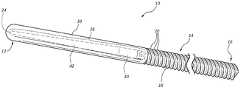
도 1은 코어 및 캡을 갖는 가이드와이어의 예시적인 실시예의 사시도.
도 2는 도 1에 도시된 바와 같은 가이드와이어에 사용될 수 있는 코어의 예시적인 실시예의 사시도.
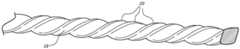
도 3a는 코어 또는 코어 재료의 하나의 부분을 그의 다른 부분에 대해 회전시키고/비틀어 리브가 형성된 코어의 예시적인 섹션의 상세도.
도 3b도 또한 코어 또는 코어 재료의 하나의 부분을 그의 다른 부분에 대해 회전시키고/비틀어 리브가 형성된 코어의 예시적인 섹션의 상세도를 도시하지만, 도 3b의 실시예는 도 3a에 도시된 만큼 여러 번 회전되고/비틀리지 않아 보다 적은 리브 또는 더욱 이격된 리브가 도시됨.
도 4는 내부에 매립된 코일을 포함하는 캡과 코어 사이의 연결 영역의 상세도.
본 발명이 다양한 변형 및 대안적인 형태를 허용하지만, 그의 특정 실시예가 예로서 도면에 도시되었고, 본 명세서에 상세히 기술된다. 그러나, 특정 실시예의 본 명세서의 설명이 본 발명을 개시된 특정 형태로 제한하도록 의도되지 않으며, 그와는 반대로, 첨부된 청구범위에 의해 한정되는 바와 같은 본 발명의 사상 및 범주 내에 속하는 모든 변형, 등가물, 및 대안을 포괄하도록 의도되는 것이 이해되어야 한다.The disclosed apparatus, components, assemblies, systems, and methods may be more clearly understood with reference to the following description taken in conjunction with the following figures, wherein like reference numerals identify identical elements. The components of the drawings are not necessarily drawn to scale.
BRIEF DESCRIPTION OF THE DRAWINGS Figure 1 is a perspective view of an exemplary embodiment of a guide wire having a core and a cap.
Figure 2 is a perspective view of an exemplary embodiment of a core that may be used for a guide wire as shown in Figure 1;
Figure 3a is a detailed view of an exemplary section of a core in which one portion of the core or core material is rotated and twisted about its other portion;
Figure 3b also shows a detail view of an exemplary section of a core that has rotated / twisted ribs about one part of the core or core material relative to its other part, while the embodiment of Figure 3b is shown as many times as shown in Figure 3a Rotated / twisted less ribs or more spaced ribs are shown.
4 is a detailed view of a connection area between a cap and a core including an embedded coil therein;
While the invention is susceptible to various modifications and alternative forms, specific embodiments thereof have been shown by way of example in the drawings and are herein described in detail. It should be understood, however, that the description herein of specific embodiments is not intended to limit the invention to the particular forms disclosed, but on the contrary, the intention is to cover all modifications, equivalents, and alternatives falling within the spirit and scope of the invention as defined by the appended claims , And alternatives are intended to be encompassed.
가이드와이어를 사용하는 의료 처치를 포함하는 의료 처치를 위한 장치, 구성요소, 조립체, 시스템, 방법 등이 본 명세서에 기술된다. 소정 실시예를 기술하고 도시하는 설명 및 첨부 도면은 가이드, 가이드와이어, 장치, 구성요소, 조립체, 시스템 등의 여러 가능한 구성 및 본 개시 내용의 다양한 태양과 특징에 따라 그것들을 사용하는 다양한 방법을 비제한적인 방식으로 보여주기 위해 작성된다. 따라서, 본 개시 내용은 기술된 특정 실시예로 제한되지 않는다. 오히려, 본 명세서에 기술된 가이드, 가이드와이어, 구성요소, 조립체, 시스템, 방법 등에 관한 것을 포함하는 본 명세서에 기술된 실시예와 관련된 본 발명의 원리는 다른 유형의 장치, 구성요소, 조립체, 시스템, 방법 등에 다양한 방식으로 적용될 수 있다. 일반적인 원리 및 특징이 과도한 실험 없이 다양한 구현/응용을 개발할 수 있게 하기에 충분히 본 명세서에 기술된다.Devices, components, assemblies, systems, methods, and the like, for medical treatment, including medical procedures using guidewires, are described herein. The description and accompanying drawings that describe and illustrate certain embodiments provide various possible configurations of a guide, a guide wire, an apparatus, an element, an assembly, a system, etc., and various methods of using them in accordance with various aspects and features of the present disclosure. It is written to show in a limited way. Accordingly, the present disclosure is not limited to the specific embodiments described. Rather, the principles of the invention in connection with the embodiments disclosed herein, including those relating to the guides, guidewires, components, assemblies, systems, methods, and the like, described herein may be applied to other types of devices, components, , Methods, and the like. The general principles and features are fully described herein to enable various implementations / applications to be developed without undue experimentation.
본 문헌은 명칭은 상이하지만 기능은 그렇지 않은 구성요소들을 구별하도록 의도하지 않는다. 하기의 논의에서 그리고 청구범위에서, 용어 "포함하는(including)", "포함하다(include)", "포함하는(comprising)" 및 "갖는다(have, has)"는 개방형 방식으로 사용되며, 따라서 "포함하지만 그에 제한되지 않는"을 의미하는 것으로 해석되어야 한다. 단어 "또는"은 반대로의 특정 사용이 명시되지 않는 한 포괄적인 의미로(즉, "및/또는") 사용된다. 용어 "가이드와이어" 및 "가이드와이어들"은 달리 명시되지 않는 한 가이드와이어 및 보다 광범위하게는 가이드 및 유사한 장치를 지칭하기 위해 사용된다. 본 명세서에 사용되는 바와 같이, "근위"는 수술 동안 임상의에 상대적으로 더 가까운 방향 또는 영역을 지칭하고, "원위"는 수술 동안 임상의로부터 상대적으로 더 멀리 떨어진 방향 또는 영역을 지칭한다.This document does not intend to distinguish between components whose names are different but whose function is not. In the following discussion and in the claims, the words "including", "includes", "comprising" and "have, has" are used in an open fashion, Shall be construed as meaning "including but not limited to". The word "or" is used in its broadest sense (i.e., "and / or" The terms "guide wire" and "guide wires" are used to refer to a guide wire and, more broadly, a guide and similar device, unless otherwise specified. As used herein, "proximal" refers to a direction or region that is relatively closer to the clinician during surgery, and "distal" refers to a direction or region that is relatively farther away from the clinician during surgery.
도 1은 의료 시술에 사용될 수 있는 예시적인 가이드 또는 가이드와이어(10)를 예시한다. 일 실시예에서, 가이드와이어(10)는 다른 장치를 가이드와이어(10)를 따라 환자 내부의 목표 위치에 도입하기 위해 사용될 수 있으며, 예컨대 가이드와이어(10)는 다른 장치를 환자의 혈관, 예컨대 환자의 요로, 혈관구조, 및/또는 다른 혈관 내로 안내하기 위해 사용될 수 있다. 도 1에 도시된 바와 같이, 가이드와이어(10)는 근위 단부(16), 원위 단부(12), 및 근위 단부(16)와 원위 단부(12) 사이의 거리에 걸쳐 이어지는 중간 영역(14)을 갖는다. 가이드와이어(10)는 코어(18)를 사용하여 형성될 수 있다. 가이드와이어(10)는 또한 캡(30), 및/또는 코팅(50)을 포함할 수 있다. 코어(18)가 부분적으로 캡(30)에 의해 덮이고 그리고/또는 전체적으로 또는 부분적으로 코팅(50)에 의해 덮일 수 있지만, 코어(18)의 부분들이 덮이지 않은 상태로 유지될 수 있다. 완전히 코어(18)로 구성되는 가이드와이어(10)를 제조하는 것이 또한 가능하다.Figure 1 illustrates an exemplary guide or guide
도 2는 가이드와이어(10)를 형성하기 위해 사용될 수 있는 예시적인 코어(18)를 예시한다. 가이드와이어는 가이드와이어에 강직성을 제공하기 위해 스테인리스 강, 다른 금속, 및/또는 다른 재료로 제조될 수 있는 중심 코어로 구성될 수 있고, 더욱 양호하게 임상의가 가이드와이어를 적절한 통로 내로 조종할 수 있게 하기 위해 증가된 가요성의 원위 또는 전방 단부 부분을 가질 수 있다. 가요성 원위 단부 부분의 근위에 있는 가이드와이어의 부분은 의료 기구를 지지하고 그것을 가이드와이어가 접근한 부위로 안내하는 데 필요한 강직성을 제공할 수 있다. 일반적으로, 가이드와이어의 코어가 가이드와이어의 전체 강성 또는 강직성을 결정할 것이다. 원위 단부의 근위에 있는 가이드와이어의 보다 큰 강성 또는 강직성은 이롭게도 가이드와이어의 조종성, 강도, 및 내구성을 증가시킨다. 코일(예컨대, 스프링 코일)이 코어의 전부 또는 일부분 위에 위치될 수 있다(예컨대, 코어는 종방향으로 코일의 중심을 통과할 수 있음). 코어 와이어는 가이드와이어가 위치되고 있을 때 그리고 카테터 또는 다른 기구가 그것을 통해 전진되고 있는 동안에 임상의가 가이드와이어의 가요성을 선택적으로 조절하도록 허용하기 위해 코일 내에서 이동가능할 수 있다. 코일을 포함하는 설계에서, 비외상성 팁(atraumatic tip)을 제공하기 위해 코일의 원위 단부에서 용접이 수행될 수 있고, 팁이 사용 동안 가이드와이어로부터 분리되지 않는 것을 더욱 양호하게 보장하기 위해 팁에 용접된 안전 와이어가 코일 내에서 근위방향으로 연장될 수 있다. 그러나, 별개의 코일이 코어 위에 사용되는 경우, 그의 합당한 전체 직경을 유지하기 위해 코일 내의 코어의 직경이 감소되거나 가이드와이어에 요구되는 전체 외경보다 작아야 한다. 코어가 가이드와이어의 강성 또는 강직성에 가장 큰 영향을 미치기 때문에, 코어의 직경을 감소시키거나 전체 가이드와이어 직경보다 작은 코어 직경을 갖는 것은 전체 가이드와이어에 대해 가능한 강성 또는 강직성을 제한한다.Figure 2 illustrates an
가이드와이어 샤프트에 강성을 추가하지 않는 스프링 코일을 가이드와이어의 코어에 감싸기보다는, 일 실시예에서 사전형성된 리브가 코어 둘레에 또는 코어 자체의 외측 표면 상에 형성될 수 있다. 이는 코어가 보다 두껍게 되거나 보다 큰 직경을 갖도록 허용하여, 가이드와이어의 증가된 강성 또는 강직성 및 보다 큰 뒤틀림-저항성 특성을 가져온다. 리브가 코어 상에 형성된 가이드와이어는 코어가 스프링 코일 내부에 형성된 동일한 외경을 갖는 가이드와이어보다 예를 들어 2.5 내지 3배 더 강성일 수 있다. 증가된 강성 또는 강직성은 이롭게도 임상의 또는 의사에게 와이어의 근위 부분으로부터 조작될 때 가이드와이어의 더욱 양호한 제어와 조종성을 허용할 수 있으며, 예컨대 가이드와이어의 근위 단부에서 수행되는 조절/조작이 가이드와이어의 원위 부분으로 더욱 양호하게 전달될 수 있으며, 예컨대 근위 영역/단부에서의 비틀림/회전이 원위 단부로 더욱 양호하게 전달될 수 있다.Rather than wrapping the spring coil on the core of the guide wire that does not add stiffness to the guide wire shaft, the preformed rib in one embodiment may be formed around the core or on the outer surface of the core itself. This allows the core to be thicker or have a larger diameter, resulting in increased stiffness or rigidity of the guide wire and greater torsion-resistant properties. The guide wire formed on the rib core may be 2.5 to 3 times more rigid than the guide wire having the same outer diameter formed inside the spring coil, for example. Increased stiffness or rigidity can advantageously allow better control and maneuverability of the guide wire when manipulated from the proximal portion of the wire to the clinician or physician, for example, adjustment / manipulation performed at the proximal end of the guide wire, For example, the torsion / rotation at the proximal region / end may be better transmitted to the distal end.
또한, 증가된 강성 또는 강직성은 가이드와이어의 좌굴(buckling) 또는 원하지 않는 과도 굽힘을 방지하는 데 도움을 줄 수 있다. 예를 들어, 가이드와이어가 환자의 요도를 통해 방광 내로 그리고 이어서 요관 내로(그리고 가능하게는 신장으로) 전진되어야 하는 의료 시술에서, 추가된 강직성 또는 강성이 가이드와이어를 더욱 가요성인 가이드와이어가 겪을 문제(complication) 없이 경로를 따라 조종하는 데 도움을 줄 수 있으며, 예컨대 보다 강직성인 가이드와이어는 방광 내에서 좌굴되거나 너무 많이 구부러질 수 있는 더욱 가요성인 가이드와이어보다 방광으로부터 요관 내로 더욱 양호하게 이동하는 것이 가능할 수 있다. 사전형성된 리브는 가이드와이어(10)에 이로운 표면 특성을 제공할 수 있다. 예를 들어, 사전형성된 리브는 가이드와이어(10)의 외측 표면 마찰을 증가시킬 수 있으며, 이는 가이드와이어가 신체 내의 원하는 위치에서 그러한 위치로부터 표류하거나 미끄러짐이 없이 더욱 양호하게 유지되는 데 도움을 줄 수 있다. 또한, 가이드와이어의 외측 표면 상에서의 추가의 마찰은 임상의 또는 의사가 근위 영역으로부터 가이드와이어를 더욱 양호하게 파지하고 비틀고/회전시키고 달리 조종하는 데 도움을 줄 수 있다. 임상의 또는 의사는 시술 동안 플라스틱 또는 라텍스 장갑을 착용할 가능성이 있을 것이고, 이러한 장갑은 가이드와이어 상에서의 충분한 표면 마찰 없이 가이드와이어 위에서 너무 쉽게 미끄러질 수 있다. 사전형성된 리브를 생성하기 위한 방법이 더욱 상세히 후술된다.Increased stiffness or rigidity can also help prevent buckling of the guide wire or unwanted transient bending. For example, in a medical procedure in which a guidewire has to be advanced through the urethra of a patient into the bladder and then into the ureter (and possibly into the kidney), the additional rigidity or rigidity may cause the guide wire to become more flexible for example, a more rigid guide wire may move better from the bladder into the ureter than a more flexible guide wire that may buckle or bulge in the bladder It can be possible. The preformed ribs can provide beneficial surface properties to the
도 2는 코어(18)의 일부분을 따라 리브(20)를 가진 예시적인 실시예를 도시한다. 도 2에 도시된 바와 같이, 코어(18)는 또한 원위 팁(24)으로 종단되는 감소된 직경의 영역(26)(이것의 일부 또는 전부가 테이퍼질 수 있음)을 포함할 수 있다. 감소된 직경의 영역(26)은 또한 캡(30)에 대한 더욱 양호한 연결을 위한 채널(22)을 포함할 수 있다. 원위 팁(24)은 부상을 피하는 데 도움을 주기 위해 무디거나 비외상성일 수 있다. 리브(20)에 더하여 또는 그 대신에, 다른 유형의 텍스처링(texturing), 홈 형성(grooving), 에칭, 및 패턴이 원하는 표면 마찰을 달성하기 위해 코어(18) 및/또는 가이드와이어(10)의 외측 표면에 추가될 수 있다.FIG. 2 illustrates an exemplary embodiment with a
리브(20)는 코어(18)의 전체 길이를 따라 연장될 수 있거나, 단지 코어(18)의 일부분만을 따라 연장될 수 있다(예컨대, 리브(20)는 단지 코어 와이어(18)의 근위 영역만을 따라 연장될 수 있거나, 감소된 직경의 영역(26)을 제외하고는 코어 와이어(18) 전부에 걸쳐 연장될 수 있음). 리브(20)는 코어(18)의 길이를 따라 서클링(circling) 또는 코일링(coiling)/스파이럴링(spiraling)하는 하나의 리지(ridge)에 의해 형성될 수 있거나, 임의의 개수의 리지 또는 리브(예컨대, 코어의 길이를 따라 코일링/스파이럴링하는 2개, 3개, 4개, 5개, 6개, 7개, 또는 8개의 리지, 또는 코어(18)를 따라 상이한 위치에 있는 더욱 많은 리지 또는 리브, 예컨대 2개 내지 100개의 리브 또는 20개 내지 70개의 리브)일 수 있다. 리브(20)는 다양한 형상과 구성으로 형성될 수 있다. 예를 들어, 리브(20)는 만곡될 수 있거나(예컨대, 둥근 단면 형상을 형성하거나, 반원형 단면 형상을 형성함), 하나 이상의 에지 및/또는 모서리(angle)를 포함할 수 있다(예컨대, 삼각형, 정사각형, 오각형, 육각형, 또는 다른 다각형 형상의 단면으로 형성됨). 하나 이상의 에지 및/또는 모서리가 형성되는 경우, 에지 및/또는 모서리는 둥근 에지 또는 모서리를 가져서, 예컨대 만곡된 및 에지가 있는 단면의 조합을 형성할 수 있다. 리브(20)는 형상이 균일할 수 있거나, 형상이 그들의 길이 또는 경로를 따라 달라질 수 있다. 리브(20)는 또한 다양한 구성으로 배열될 수 있다. 예를 들어, 리브(20)는 코어(18)와 가이드와이어(10)를 따라 나선형 형상으로 배열될 수 있다. 나선형 형상은 코어(18)의 길이를 따라 아래로 볼 때 시계 방향 또는 반시계 방향으로 권취될 수 있다. 선택적으로, 리브(20)는 코어(18)와 가이드와이어(10)의 길이를 따라 서로 인접하게 정렬되는 복수의 작은 원(circlet) 또는 일련의 평행한 리브로서 형성될 수 있으며, 예컨대 각각의 리브는 코어(18)의 종축을 중심으로 코어의 외측 표면 상에 원을 형성할 수 있다. 다른 구성, 예컨대 나선형 및 비-나선형 또는 원형 형상, 코어(18)의 길이 및/또는 곡률을 따른 사인곡선형 형상 등의 조합이 또한 가능하다. 리브(20)는 최적 표면 특성, 예컨대 최적 마찰 특성(위의 외측 표면 마찰 특성의 논의 참조)을 가이드와이어에 제공하도록 형상화되고 배열될 수 있다.The
코어(18)의 리브(20)는 코어(18) 또는 코어(18)를 형성하기 위해 사용되는 재료(예컨대, 가이드와이어 코어 재료)를 원하는 형상/구성으로 기계가공 및/또는 연삭하는 것, 코어(18) 또는 코어(18)를 형성하기 위해 사용되는 재료의 일부분을 비틀고/회전시키는 것, 성형, 사출 성형, 레이저 절단 및/또는 에칭, 다른 절단 및/또는 에칭, 3D 인쇄 등을 포함하는 다양한 방식으로 형성될 수 있다. 그러한 단일체 구성에 의해, 제조 실패의 가능성이 최소화되고, 제조 비용도 마찬가지이다. 리브(20)는 임상의가 가이드와이어를 조작하는 것을 보조할 수 있고, 가이드와이어를 환자 내에서 제위치로 유지시키는 데 도움을 줄 수 있으며, 이는 임상의 및 환자 둘 모두에게 유리하다. 또한, 단지 보다 작은 내부 코어 위에 스프링 코일을 갖는 것보다는 코어의 외측 표면 상에 리브(20)를 형성하는 것이 여러 이점, 감소된 비용(예컨대, 별개의 스프링 코일이 요구되지 않음)을 제공하고, 제조를 보다 용이하게 하며(추적하고 연결할 보다 적은 부품), 가이드와이어를 더욱 신뢰성 있게 한다(보다 적은 부품은 보다 적은 고장 및 결함 가능성을 의미함).The
도 2는 리브(20)가 센터리스 연삭(centerless grinding) 공정을 사용하는 기계가공에 의해 코어(18) 또는 코어(18)를 형성하기 위해 사용되는 재료 상에 형성된 실시예를 도시한다. 센터리스 연삭 공정은 리브를 코어(18) 또는 코어(18)를 형성하기 위해 사용되는 재료의 외측 본체를 따라 다양한 형상과 구성(위에서 논의된 형상과 구성을 참조)으로 제공하기 위해 사용될 수 있다. 센터리스 연삭은 가이드와이어 코어 재료(예컨대, 바 또는 와이어)의 표면을 연삭하는 공정이다. 리브를 직접 코어(18)의 외측 표면 상에 형성하는 것은 가이드와이어(10)가 (예컨대, 별개의 스프링 코일 내부에 있는 코어에 비해) 보다 두꺼운 코어를 갖도록 그리고 가이드와이어의 길이 전체에 걸쳐 최적 수준의 강직성 및 가요성으로 형성되도록 허용한다. 예컨대 코어의 직경을 좁히고 그리고/또는 코어의 길이를 따라 더욱 큰 가요성을 허용하는 감소된 직경의 홈 또는 채널을 리브들 사이에 제공하도록 외측 표면의 많은 부분을 기계가공함으로써 일정 정도의 가요성이 코어(18)에 추가될 수 있다. 어느 경우든, 이러한 방법은 코어(18)와 가이드와이어(10)의 원하는 강성 또는 강직성을 최적화시키는 것을 보다 용이하게 한다. 또한, 별개의 스프링 코일에 의해 둘러싸인 좁은 코어 와이어로 형성되는 동일한 외경의 가이드와이어로 가능할 것보다 큰 강성 및 강직성이 이러한 유형의 코어(18)와 가이드와이어(10)로 가능하다.Figure 2 shows an embodiment in which the
센터리스 연삭에서, 코어(18) 또는 코어(18)를 형성하기 위해 사용되는 재료(예컨대, 가이드와이어 코어 재료)는 상이한 속도로 동일한 방향으로 회전하는 2개의 연삭 휠(grinding wheel)과 유지 플랫폼(holding platform) 사이에서 유지될 수 있다. 하나의 연삭 휠이 고정된 축 상에 있고, 가이드와이어(10)에 인가되는 힘이 유지 플랫폼에 대항하여 하향으로 지향되도록 회전한다. 이러한 휠은 접촉점에서 가이드와이어(10)보다 높은 속도를 가짐으로써 연삭 작용을 수행한다. 조정 휠로 알려진 다른 하나의 휠은 이동가능하다. 이러한 휠은 가이드와이어(10)에 측방향 압력을 인가하도록 위치되고, 가이드와이어(10)를 포획하기 위해 매우 거친 또는 고무-접합된 연마재를 가질 수 있다. 2개의 휠의 서로에 대한 속도는 연삭 작용을 제공하고, 재료가 가이드와이어(10)로부터 제거되는 비율을 결정한다. 작업 동안, 가이드와이어(10)는 조정 휠과 함께, 접촉점에서 동일한 선속도로 그리고 미끄러짐 없이 선회한다. 연삭 휠은 보다 빨리 선회하여, 접촉점에서 가이드와이어(10)의 표면을 지나 미끄러지고, 그것이 통과할 때 재료의 칩을 제거한다.In the centerless grinding, the material used to form the core 18 or the core 18 (e.g., the guide wire core material) includes two grinding wheels that rotate in the same direction at different speeds, a holding platform. One grinding wheel is on a fixed axis and the force applied to the
도 3a 및 도 3b는 리브가 코어(18) 또는 코어(18)를 형성하기 위해 사용되는 재료 상에, 코어 또는 재료의 하나의 부분 또는 단부를 코어 또는 재료의 다른 부분 또는 단부에 대해 비틀고/회전시킴으로써 형성된 리브형성된 코어(18)의 일부분을 예시한다. 코어 또는 재료의 하나의 부분 또는 단부는 다른 하나의 부분 또는 단부가 비틀리고/회전되는 동안에 제위치로 또는 고정되어 유지될 수 있거나, 이러한 부분들 또는 단부들은 상이한 속도로 그리고/또는 상이한 방향으로 회전될 수 있다. 다른 부분을 제위치로 유지시킨 상태에서 하나의 부분을 회전시키는 것은 코어 또는 재료가 비틀리고 리브(20)를 형성하게 한다. 초기의 사전형성된 가이드와이어 코어 재료가 이 방법에 사용될 수 있거나, 새로운 가이드와이어 코어 재료가 예컨대 압출, 성형, 또는 다른 수단에 의해 이 방법에 사용하기 위해 제조될 수 있다. 초기의 사전형성된 가이드와이어 코어 재료 또는 새로이 형성된 코어 재료는 비-원형 형상의 단면(예컨대, 직사각형, 정사각형, 오각형, 육각형, 다른 다각형 단면, 또는 이들 중 하나와 유사하지만 둥근 코너를 가진 단면 형상)을 가질 수 있다. 형상화된 단면의 에지 또는 코너는 원하는 리브(20)를 형성하는 데 도움을 줄 수 있다. 임의의 단면 형상이 사용될 수 있지만, 예를 들어 정사각형 또는 대략 정사각형인 단면이 비틀림/회전 전에 그리고 그 동안 회전되는 단부를 파지하기 위한 동일한 직각을 허용하고, 균일한 리지를 형성한다. 초기의 사전형성된 가이드와이어 코어 재료 또는 새로이 형성된 코어 재료의 하나의 부분 또는 단부는 다른 부분 또는 단부가 비틀리고/회전되는 동안에 제위치로 고정될 수 있거나, 양쪽 부분/단부가 상이하게 회전될 수 있다.Figures 3a and 3b illustrate a method in which ribs are formed by twisting / rotating one portion or end of a core or material against another portion or end of the core or material on the material used to form the core 18 or
코어 또는 가이드와이어 코어 재료의 상이한 부분/영역이 상이한 양으로 비틀려 다양한 외측 표면을 형성할 수 있으며, 예컨대 하나의 영역이 다른 영역보다 길이의 cm당 더욱 많은 선회부(turn)를 가질 수 있고, 하나의 영역이 하나의 방향으로 코일링될 수 있는 한편, 다른 영역이 다른 방향으로 코일링된다. 도 3a 및 도 3b는 상이한 양으로 비틀리고/회전된 부분/영역/가이드와이어를 도시한다. 비틀림/회전은 코어 또는 가이드와이어 코어 재료를 소성 변형시킬 수 있다. 필요할 경우, 원하는 코일링된 형상이 획득된 후에, 코어(18) 또는 재료가 변형을 영구적으로 만들기 위해 열-처리되거나 달리 처리될 수 있다. 또한, 에지 및/또는 코너가 코일링된 리브를 형성하기 위한 회전/비틀림 전에 또는 후에 그것들을 더욱 비외상성으로 만들기 위해 둥글게 될 수 있다. 길이의 센티미터당 코일의 개수는 예컨대 보다 넓거나 보다 좁은 코일 형상을 허용하고 마찰 특성을 최적화시키기 위해 달라질 수 있다.Different portions / regions of the core or guide wire core material may be twisted in different amounts to form various outer surfaces, such that one region may have more turns per cm of length than the other regions, One region can be coiled in one direction while the other region is coiled in the other direction. Figures 3a and 3b illustrate the portion / area / guide wire twisted / rotated in different amounts. Torsion / rotation may plastically deform the core or guide wire core material. If desired, after the desired coiled shape is obtained, the core 18 or material may be heat-treated or otherwise treated to make the deformation permanent. In addition, the edges and / or the corners may be rounded to make them more non-traumatic before or after rotation / torsion to form the coiled ribs. The number of coils per centimeter of length may be varied, for example, to allow for a wider or narrower coil shape and to optimize the friction characteristics.
코어(18)와 가이드와이어(10)의 외경은 환자 내에서의 그의 용도에 의해 결정된다. 일 실시예에서, 코어(18) 및/또는 전체 가이드와이어(10)는 0.008 인치 내지 0.05 인치, 0.01 인치 내지 0.04 인치, 0.015 인치 내지 0.025 인치, 또는 0.3 인치 내지 0.4 인치의 외경을 갖는다. 예로서, 비뇨기과 사용을 위한 코어 또는 가이드와이어 외경은 0.035 인치 내지 0.038 인치 범위 내에 있을 수 있는 한편, 혈관 코어 또는 가이드와이어 외경은 0.018 인치 내지 0.025 인치 범위 내에 있을 수 있다(예컨대, ±0.002 인치 내). 0.008 인치 내지 0.018 인치 범위와 같은 작은 코어 또는 가이드와이어 외경이 신경혈관 사용에 가능하다.The outer diameter of the
코어(18)는 금(방사선 불투과성 특성), 니티놀(특출한 형상-기억 특성을 갖는 니켈-티타늄 합금; 다른 재료와 함께 사용될 수 있음), 백금(방사선 불투과성 특성), 스테인리스 강, 니켈을 함유한 스테인리스 강, 티타늄, 텅스텐, 유리섬유 복합재, 탄소 섬유, 형상 기억 합금, 형상 기억 재료, 및 다른 적합한 재료를 포함하는 다양한 재료들 중 하나 이상으로부터 형성될 수 있다. 일 실시예에서, 코어 와이어는 스테인리스 강 코어 와이어이다.The core 18 may be made of a material selected from the group consisting of gold (radiopaque property), Nitinol (a nickel-titanium alloy with exceptional shape-memory properties; may be used with other materials), platinum (radiopaque property), stainless steel, And may be formed from one or more of a variety of materials including stainless steel, titanium, tungsten, glass fiber composites, carbon fibers, shape memory alloys, shape memory materials, and other suitable materials. In one embodiment, the core wire is a stainless steel core wire.
코어 와이어는 코어(18)의 감소된 직경의 영역(26)에 대응하는 가이드와이어의 부분에서 가이드와이어(10)에 추가된 가요성을 제공하기 위해 도 2에 도시된 바와 같이 감소된 직경의 영역(26)을 포함할 수 있다. 감소된 직경의 영역(26)은 가이드와이어(10)의 원위 단부(12)에 보다 큰 가요성을 부여하기 위해 원위 단부(12)에 위치될 수 있다. 더욱 큰 가요성의 원위 단부(12) 또는 원위 영역을 갖는 것은 가이드와이어의 개선된 가항성(navigability)을 허용하며, 예컨대 그것은 원위 팁을 원하는 방향으로 그리고/또는 원하는 통로 또는 혈관 내로 조종하는 것을 보다 용이하게 할 수 있다. 단부에서 단부까지 감소된 직경의 영역(26)의 길이를 따라, 감소된 직경의 영역(26)은 완전히 또는 부분적으로 테이퍼질 수 있다. 테이퍼진 영역은 연속적이거나 불연속적일 수 있다. 테이퍼의 정도(grade)가 또한 감소된 직경의 영역(26)의 길이를 따라 변할 수 있다.The core wire may have a reduced diameter area as shown in Figure 2 to provide added flexibility to the
도 2에서, 코어(18)의 감소된 직경의 영역(26)은 (코어(18)의 리브형성된 부분으로부터 순서대로) 채널(22), 테이퍼지지 않은 영역(40), 및 팁(24)에서 종단되는 테이퍼진 영역(42)을 포함하는 것으로 도시된다. 채널(22)은 캡(30)에 대한 코어(18)의 확고한 연결을 용이하게 한다. 예를 들어, 캡(30)은 채널(22) 내부에 끼워맞추어져(예컨대, 스냅 끼워맞춤, 나사식 끼워맞춤, 또는 다른 끼워맞춤으로) 캡을 코어(18)에 고정시키는 데 도움을 주는 돌출부 또는 립(lip)을 포함할 수 있다. 채널(22)은 감소된 직경의 부분 상의 인접한 리지 또는 리브에 의해 형성될 수 있거나, 다른 균일한 외측 표면 영역 내에 형성되는 홈일 수 있다. 테이퍼지지 않은 영역(40)은 팁(24)까지 연장될 수 있거나, 감소된 직경의 영역(26)의 길이를 따라 임의의 지점에서 종단될 수 있다. 테이퍼진 영역(42)은 채널(22)로부터 팁(24)까지 연장될 수 있거나, 단지 감소된 직경의 영역(26)의 일부분에 걸쳐 연장될 수 있다. 일 실시예에서, 감소된 직경의 영역(26)은 코어 와이어(18)의 일부분을 원하는 형상/구성으로 연삭/기계가공함으로써 형성될 수 있다. 선택적으로, 코어는, 각각이 위에서 논의된 것과 유사한 특징/특성을 가질 수 있는 2개의 감소된 직경의 영역을 코어(18)의 대향하는 단부들 상에 포함할 수 있다.In Figure 2, the reduced
팁(24)과 감소된 직경의 영역(26)은 감소된 직경의 영역(26) 위에 그리고 그 둘레에 끼워맞추어지는 캡(30)에 의해 덮일 수 있다. 코어가 대향하는 단부들 상에 2개의 감소된 직경의 영역을 포함하는 경우, 양쪽 영역이 캡(30)에 의해 덮일 수 있다. 캡(30)은 양 단부가 개방되거나 일 단부가 폐쇄된 중공 중심부(hollow center)를 포함할 수 있다. 캡(30)은 슬리브로서 형성될 수 있다. 중공 중심부는 코어(18)의 감소된 직경의 영역(26) 위에 꼭 맞게 끼워맞추어지도록 형상화될 수 있다. 캡(30)은 다양한 재료들 중 하나의 또는 하나 초과의 재료로 제조될 수 있다. 일 실시예에서, 캡(30)은 중합체 재료, 예컨대 폴리에틸렌, 전술한 재료들 중 2가지 이상의 조합, 및/또는 다른 재료로 제조될 수 있다. 일 실시예에서, 캡(30)은 윤활성인 외측 표면을 갖는다. 일 실시예에서, 캡(30) 자체의 재료가 윤활성이다. 일 실시예에서, 캡(30)은 윤활성인 외측 코팅을 포함한다. 일 실시예에서, 캡(30) 또는 그 상의 코팅의 재료는 친수성이다. 또한, 캡(30)의 외측 표면의 일부 또는 전부 상에 몇몇 리브(예컨대, 리브(20)와 유사함)가 있을 수 있다. 캡(30)은 가이드와이어(10)의 균일한 또는 대략 균일한 외경을 유지시키고 가이드와이어(10)의 길이를 따라 코어(18)와 캡(30) 사이의 매끄러운 전이부를 갖기 위해 코어의 나머지(즉, 감소된 직경의 영역(26)의 일부가 아닌 코어의 영역)의 외경과 동일하거나 유사한(예컨대, ±0.1 인치) 외경을 가질 수 있다. 선택적으로, 캡(30)은 균일한 직경을 가질 수 있거나, 예컨대 가이드와이어의 중심을 향하는 캡의 에지에서의 직경이 캡의 반대편 단부 또는 팁에서의 직경보다 크도록 그의 단부 부근에서 보다 좁은 직경으로 테이퍼질 수 있다. 가이드와이어의 중심을 향하는 에지는 일반적으로 코어로부터 캡까지 직경의 갑작스러운 변화를 회피하기 위해 그것이 맞닿는 코어의 부분과 동일하거나 유사한 직경을 가질 것이다. 캡(30)의 단부 또는 팁은 부상을 피하기 위해 무디거나 비외상성일 수 있다. 캡의 단부 또는 팁에서의 보다 좁은 직경은 가이드와이어의 조종 및/또는 새로운 혈관 또는 분지 혈관 내로의 진입을 도울 수 있다.The
캡(30)은 가이드와이어의 원위 단부(12)와 가이드와이어의 중간 부분(14)에서 감소된 직경의 영역(26) 위로 활주하여 채널(22)과 결합하도록 설계될 수 있다. 채널(22)은 스냅-끼워맞춤 연결부로서 구성될 수 있고, 캡(30)의 일부분이 채널(22) 내에 스냅체결되는 상태로 캡(30)과 결합할 수 있다. 스냅-끼워맞춤 연결부는 제조 동안 형성될 수 있으며, 예컨대 캡은 채널(22)과 끼워맞추기 위해 성형, 3D 인쇄 등의 공정 동안 형성되는 돌출부를 포함할 수 있다. 스냅-끼워맞춤 연결은 2개의 부품을 조립하는 데에 있어서 완료하기에 신속하고 용이한 단계이기 때문에 가장 간단하고 가장 비용-효율적인 방식일 수 있어서, 이러한 부품들을 대량 생산에 대해 이상적으로 만든다. 이는 더욱 많은 구성요소와 공구를 필요로 하는 단계 동안 더욱 빈번히 발생하는 잘못된 조립의 위험을 감소시킨다. 그러나, 나사식 연결, 접착제, 화학적 접합 등과 같은 다른 확고한 체결구 연결이 또한 가능하다.The
캡(30)은 코어(18) 또는 리브(20)를 포함하는 코어(18)의 영역보다 낮은 표면 마찰을 갖거나 더욱 윤활성일 수 있다. 캡(30) 및 그에 따른 가이드와이어(10)의 원위 단부의 보다 낮은 표면 마찰은 가이드와이어(10)를 신체 내의 원하는 통로를 통해 그리고 원하는 위치로 더욱 매끄럽게 조종하고 환자에게 더욱 부드럽게 하는 데 도움을 주는 한편, 리브형성된 영역의 보다 큰 표면 마찰은 가이드와이어가 그의 위치를 유지시키고 원하지 않는 이동 없이 목표 위치에 체류하는 데 도움을 주고 임상의가 가이드와이어(10)를 더욱 양호하게 파지하고 조작하도록 허용한다. 위에서 논의된 바와 같이, 코어(18)의 감소된 직경의 영역(26)은 가이드와이어(10)가 가요성이고 덜 강직성이도록 허용하고, 캡(30)은 바람직하게는 또한 가이드와이어(10)의 원위 영역에서 보다 큰 가요성을 용이하게 한다. 캡(30)은 비외상성 단부 및/또는 팁을 제공하여, 가이드와이어가 환자의 신체 내로 삽입되고 그를 통해 조종될 때 부상 가능성을 감소시킬 수 있다. 캡(30)은 리브(20) 또는 리브(20)를 포함하는 영역에 맞닿고 코어(18)와 캡(30) 사이의 매끄러운 또는 비교적 매끄러운 전이부를 제공하여, 리브형성된 또는 코일링된 영역으로부터 원위 단부로의 갑작스러운 그리고 급격한 전이를 회피할 수 있다. 도 4는 코어와 캡 사이의 연결 영역의 상세도를 도시한다. 선택적으로, 캡(30)은 텍스처화될 수 있거나, 보다 낮은 마찰을 위해 매끄러운 표면을 가질 수 있다.The
캡(30)은 보강될 수 있다. 예를 들어, 캡(30)은 지지 격자, 코일, 와이어, 브레이드(braid), 또는 다른 지지부를 캡(30)의 벽 내에 포함할 수 있다. 일 실시예에서, 캡(30)은 중합체 재료로 형성될 수 있고, 코일(예컨대, 스프링 코일)이 중합체 재료 내부에 형성된다. 스프링 코일이 높은 정도의 가요성을 유지하면서 캡에 강도를 추가할 수 있다. 도 4는 코어와 캡 사이의 연결 영역의 상세도를 도시하며, 캡은 그 내부에 매립된 코일(52)을 포함한다.The
일 실시예에서, 슬리브 또는 캡(30)은 주로 또는 완전히 스프링 코일로서 가이드와이어(10)의 감소된 직경의 영역(26) 위에 형성될 수 있다. 스프링 코일은 균일한 또는 대략 균일한 외경을 유지하도록 그리고 코어(18)의 리브형성된 영역으로부터 매끄러운 전이부를 생성하도록 설계될 수 있다. 스프링 코일의 외경은 코어 와이어(18)의 나머지의 외경과 동일하거나 유사하게 제조될 수 있다(위의 코어 와이어(18)의 외경의 논의 참조).In one embodiment, the sleeve or
가이드와이어(10)는 또한 다양한 목적들 중 하나 이상을 위해 그 상에 하나 이상의 코팅 또는 외측 층(50)을 포함할 수 있다. 코팅(들) 및/또는 층(들)은 코어(18), 캡(30), 및/또는 둘 모두 상에 있을 수 있다. 코팅(들) 및/또는 층(들)은 스프레이 코팅(spray-coating), 딥 코팅(dip coating), 다른 코팅 방법, 및/또는 재료 또는 하나 초과의 재료를 가이드와이어의 일부분 위에 적층(layering)시키는 것에 의해 적용될 수 있다. 가이드와이어(10)는 플라스틱 또는 중합체 재료, 예컨대 폴리테트라플루오로에틸렌(PTFE), 팽창 폴리테트라플루오로에틸렌(ePTFE), 폴리에틸렌, HDPE, LDPE 등으로 코팅되거나 적층될 수 있다. 다른 코팅(들) 및/또는 층(들)은 친수성(더욱 부드러운 조종 및 우수한 추적성을 위해 윤활시킴), 항혈전성(anti-thrombogenic)/헤파린(heparin)(응고를 억제함), 소수성(hydrophobic)(임상의에 대한 촉각 반응을 향상시켜 외과적 조종 동안 더욱 민감한 촉감을 생성함), 또는 실리콘(마찰을 감소시킴)일 수 있다. 또한, 가이드와이어(10)의 외측 표면, 특히 원위 영역 또는 캡(30)은 마찰을 감소시키기 위해 윤활성, 친수성, 또는 소수성 코팅으로 코팅되거나 적층될 수 있다. 코팅(들) 및/또는 층(들)은 코어 및 캡 둘 모두에 걸쳐 연장되고, 코어와 캡 사이의 매끄러운, 중단되지 않는 외측 표면 전이부를 형성할 수 있다.The
의료 처치의 방법 또는 의료 시술에서 가이드와이어를 사용하는 방법은 사전형성된 리브(예컨대, 위에서 논의된 리브(20)와 동일하거나 유사함)를 가진 코어(예컨대, 위에서 논의된 코어(18)와 동일하거나 유사함)를 포함하는 가이드와이어(예컨대, 위에서 논의된 가이드와이어(10)와 동일하거나 유사함)를 획득하는 단계를 포함할 수 있다. 사전형성된 리브는 코어의 전부 또는 일부분(예컨대, 근위 부분)을 따라 있을 수 있다. 가이드와이어는 또한 캡(예컨대, 위에서 논의된 캡(30)과 동일하거나 유사함)을 포함할 수 있다. 캡은 코어의 감소된 직경의 영역 위에, 예컨대 코어의 원위 단부에 위치될 수 있다. 가이드와이어의 원위 단부가 환자의 체강/혈관 내로 삽입될 수 있고, 환자의 신체 내의 원하는 목표 위치로 조종될 수 있다. 가이드와이어는 이어서 카테터 또는 다른 장치(들)를 가이드와이어를 따라 환자의 신체 내부의 목표 위치에 도입하기 위해 사용될 수 있으며, 예컨대 가이드와이어는 카테터, 스코프(scope), 리드(lead), 또는 다른 의료 장치를 환자의 요로, 혈관구조, 및/또는 다른 혈관과 같은 환자의 혈관 내로 안내하기 위해 사용될 수 있다. 비뇨기과/내시경비뇨기과 의료 시술에서, 가이드와이어는 요로 내로 삽입될 수 있다(예컨대, 요도, 방광을 통해 요관 내로, 그리고 또한 신장까지 또는 그 부근으로 이동될 수 있음). 카테터 및/또는 요관경이 가이드와이어를 통해 전진될 수 있으며, 이때 가이드와이어는 카테터 및/또는 요관경이 횡단할 경로를 제공한다.The method of medical treatment or the method of using the guidewire in a medical procedure is similar to that of a core (e.g.,
위의 장치, 구성요소, 시스템, 조립체, 방법 등은 일반적으로 의료 처치를 위한 가이드 및 가이드와이어에 적용되는 것으로 기술되었지만; 기술된 원리는 다른 유형의 장치, 구성요소, 시스템, 조립체, 방법 등에 적용될 수 있다. 또한, 본 명세서의 일 실시예에 기술된 특징은 일반적으로 본 명세서의 다른 실시예에 기술된 특징과 조합될 수 있다. 본 명세서에 개시되고 청구된 모든 장치, 구성요소, 시스템, 조립체, 방법 등은 본 개시 내용을 고려하여 과도한 실험 없이 제조되고 실행될 수 있다.While the above devices, components, systems, assemblies, methods, etc. have been described as generally applicable to guides and guidewires for medical treatment, The principles described may be applied to other types of devices, components, systems, assemblies, methods, and the like. Further, the features described in one embodiment of the present specification can be generally combined with the features described in the other embodiments of the present specification. All apparatus, components, systems, assemblies, methods and the like disclosed and claimed herein may be made and executed without undue experimentation in light of this disclosure.
본 발명의 가이드, 가이드와이어, 장치, 구성요소, 시스템, 조립체, 방법 등이 특정 변형과 예시적인 도면에 관하여 기술되었을 수 있지만, 본 발명이 그렇게 제한되지 않고, 이러한 가이드, 가이드와이어, 장치, 구성요소, 시스템, 조립체, 방법 등에 변형이 적용될 수 있는 것이 당업자에게 명백할 것이다. 예를 들어, 본 명세서에 기술된 방법, 사용, 및/또는 단계에 관하여, 청구범위에 의해 한정되는 바와 같은 본 발명의 개념, 사상, 및 범주로부터 벗어남이 없이 본 명세서에 기술된 단계, 사용, 단계의 시퀀스/순서 등에서 변형이 이루어질 수 있다. 또한, 소정 단계가 가능할 때 병렬 공정으로 동시에 수행될 수 있을 뿐만 아니라 전술된 바와 같이 순차적으로 수행될 수 있다. 따라서, 본 개시 내용의 사상 내에 있거나 청구범위에서 확인되는 발명과 동등한 본 발명의 변형이 존재하는 경우에, 본 특허가 또한 그들 변형을 포괄할 것으로 의도된다.While the present invention has been described with respect to particular variations and illustrative figures, it will be appreciated that the present invention is not so limited, and that such guides, guidewires, devices, components, systems, assemblies, It will be apparent to those skilled in the art that variations may be applied to elements, systems, assemblies, methods, and the like. For example, without limitation to the concepts, spirit, and scope of the present invention as defined by the claims, with respect to the methods, uses, and / or steps described herein, The sequence / order of the steps, and the like. In addition, not only can certain steps be performed simultaneously in a parallel process when possible, but also can be performed sequentially as described above. Accordingly, it is intended that the present patent be also encompassed within the spirit of the present disclosure or that such modifications are equivalent to the inventions identified in the claims.
Claims (17)
Translated fromKorean코어(core)를 포함하고, 상기 코어는
상기 코어의 제1 부분을 따라 형성되는 하나 이상의 리브(rib)들로서, 상기 코어의 상기 제1 부분은 제1 직경을 갖고, 상기 하나 이상의 리브들은 상기 가이드와이어의 외측 표면의 마찰을 증가시키는, 상기 하나 이상의 리브들; 및
상기 제1 직경보다 작은 제2 직경을 갖는, 상기 제1 부분의 원위에 있는 감소된 직경(reduced diameter)의 영역을 포함하는, 가이드와이어.As a guidewire,
A core comprising a core,
Wherein the first portion of the core has a first diameter and the one or more ribs increase friction of an outer surface of the guide wire, One or more ribs; And
And a reduced diameter region on the circle of the first portion having a second diameter less than the first diameter.
가이드와이어를 획득하는 단계로서, 상기 가이드와이어는
코어를 포함하고, 상기 코어는 제1 직경을 갖는 상기 코어의 제1 부분의 외측 표면을 따라 형성되는 하나 이상의 리브들을 갖고, 상기 하나 이상의 리브들은 상기 가이드와이어의 표면 마찰을 증가시키는, 상기 획득하는 단계;
상기 가이드와이어의 원위 단부를 환자의 신체의 혈관 내로 삽입하는 단계; 및
상기 가이드와이어를 상기 환자의 신체 내의 원하는 위치로 조종하는 단계를 포함하는, 방법.As a method of medical treatment,
Obtaining a guide wire, wherein the guide wire
Wherein the core has one or more ribs formed along an outer surface of a first portion of the core having a first diameter and the one or more ribs increase surface friction of the guide wire, step;
Inserting a distal end of the guide wire into a blood vessel of a patient's body; And
And manipulating the guide wire to a desired position within the body of the patient.
제1 단부 및 제2 단부를 갖는 긴(elongate) 가이드와이어 코어 재료를 획득하는 단계;
상기 긴 가이드와이어 코어 재료의 표면 상에 하나 이상의 리브들을 형성하는 단계로서, 상기 하나 이상의 리브들은 상기 가이드와이어의 외측 표면 상에 가시적인 패턴을 형성하는, 상기 형성하는 단계를 포함하는, 방법.A method of manufacturing a guide wire,
Obtaining an elongate guide wire core material having a first end and a second end;
Forming one or more ribs on a surface of the elongated guide wire core material, wherein the one or more ribs form a visible pattern on an outer surface of the guide wire.
Applications Claiming Priority (3)
| Application Number | Priority Date | Filing Date | Title |
|---|---|---|---|
| US201461985887P | 2014-04-29 | 2014-04-29 | |
| US61/985,887 | 2014-04-29 | ||
| PCT/US2015/028366WO2015168335A1 (en) | 2014-04-29 | 2015-04-29 | Kink-resistant guidewire with improved rigidity |
Publications (2)
| Publication Number | Publication Date |
|---|---|
| KR20160146776Atrue KR20160146776A (en) | 2016-12-21 |
| KR102125315B1 KR102125315B1 (en) | 2020-06-22 |
Family
ID=54359311
Family Applications (1)
| Application Number | Title | Priority Date | Filing Date |
|---|---|---|---|
| KR1020167030694AActiveKR102125315B1 (en) | 2014-04-29 | 2015-04-29 | Kink-resistant guidewire with improved rigidity |
Country Status (9)
| Country | Link |
|---|---|
| US (1) | US9855408B2 (en) |
| EP (1) | EP3116582B1 (en) |
| KR (1) | KR102125315B1 (en) |
| CN (1) | CN106456942B (en) |
| AU (1) | AU2015253183B2 (en) |
| CA (1) | CA2943692C (en) |
| ES (1) | ES2762648T3 (en) |
| MX (1) | MX376737B (en) |
| WO (1) | WO2015168335A1 (en) |
Families Citing this family (8)
| Publication number | Priority date | Publication date | Assignee | Title |
|---|---|---|---|---|
| CN106456942B (en) | 2014-04-29 | 2019-11-19 | C·R·巴德股份有限公司 | Kink-resistant guidewire with improved stiffness |
| US10953204B2 (en)* | 2017-01-09 | 2021-03-23 | Boston Scientific Scimed, Inc. | Guidewire with tactile feel |
| SE540134C2 (en)* | 2017-04-04 | 2018-04-10 | Madeleine Ramstedt | Indwelling urethral device |
| EP4059557A3 (en)* | 2017-09-30 | 2022-09-28 | Asahi Intecc Co., Ltd. | Guide wire |
| CN107716142A (en)* | 2017-11-14 | 2018-02-23 | 上海核工程研究设计院有限公司 | A kind of nuclear power plant voltage stabilizer sprayer rotation water core of increasing material manufacturing |
| CN107802943A (en)* | 2017-12-06 | 2018-03-16 | 陈佳 | The special Auxiliary support seal wire of ureteral distortion |
| CN110193132B (en)* | 2019-05-17 | 2021-11-23 | 业聚医疗器械(深圳)有限公司 | Balloon catheter |
| US20240374871A1 (en)* | 2023-05-11 | 2024-11-14 | Abbott Cardiovascular Systems Inc. | Twisted guidewire |
Citations (5)
| Publication number | Priority date | Publication date | Assignee | Title |
|---|---|---|---|---|
| JPH05137796A (en)* | 1990-07-06 | 1993-06-01 | Cardiometrics Inc | Guide wire assemblage possible to torque, having electrical function and male-female connector, and using device therefor |
| US20040142643A1 (en)* | 2003-01-17 | 2004-07-22 | Scimed Life Systems, Inc. | Straightening and centerless grinding of wire for use with medical devices |
| US20040215109A1 (en)* | 2003-04-23 | 2004-10-28 | Pingleton Edward D. | Helical guidewire |
| US20080064989A1 (en)* | 2006-09-13 | 2008-03-13 | Boston Scientific Scimed, Inc. | Crossing guidewire |
| US20080255518A1 (en)* | 2007-04-13 | 2008-10-16 | Neometrics, Inc. | Medical guidewire |
Family Cites Families (17)
| Publication number | Priority date | Publication date | Assignee | Title |
|---|---|---|---|---|
| CA1232814A (en) | 1983-09-16 | 1988-02-16 | Hidetoshi Sakamoto | Guide wire for catheter |
| US4991602A (en) | 1989-06-27 | 1991-02-12 | Flexmedics Corporation | Flexible guide wire with safety tip |
| DE69534748T2 (en) | 1994-09-02 | 2006-11-02 | Volcano Corp. (n.d, Ges.d.Staates Delaware), Rancho Cordova | ULTRAMINIATUR PRESSURE SENSOR AND GUIDE WIRE THEREFORE |
| EP0828524A2 (en) | 1995-05-05 | 1998-03-18 | Advanced Cardiovascular Systems, Inc. | Intraluminal device with lubricious surface |
| US6019736A (en) | 1995-11-06 | 2000-02-01 | Francisco J. Avellanet | Guidewire for catheter |
| US6113557A (en) | 1997-06-20 | 2000-09-05 | Medtronic Ave, Inc. | Variable stiffness angioplasty guide wire |
| US6142958A (en) | 1998-12-23 | 2000-11-07 | Radi Medical Systems Ab | Sensor and guide wire assembly |
| US6926725B2 (en) | 2002-04-04 | 2005-08-09 | Rex Medical, L.P. | Thrombectomy device with multi-layered rotational wire |
| US7169118B2 (en) | 2003-02-26 | 2007-01-30 | Scimed Life Systems, Inc. | Elongate medical device with distal cap |
| US20040167439A1 (en) | 2003-02-26 | 2004-08-26 | Sharrow James S. | Guidewire having textured proximal portion |
| ITMI20031294A1 (en) | 2003-06-25 | 2004-12-26 | Twinex S R L | CONNECTION FOR THE CONNECTION OF A FOOTWEAR TO A SNOW TABLE AND SIMILAR. |
| JP4141336B2 (en)* | 2003-06-26 | 2008-08-27 | 朝日インテック株式会社 | Manufacturing method of medical guide wire |
| US8043232B2 (en) | 2005-08-05 | 2011-10-25 | Cook Medical Technologies Llc | High performance wire guide |
| US8231927B2 (en) | 2007-12-21 | 2012-07-31 | Innovatech, Llc | Marked precoated medical device and method of manufacturing same |
| JP5147569B2 (en)* | 2008-06-30 | 2013-02-20 | テルモ株式会社 | Guide wire |
| US20130231752A1 (en) | 2012-03-02 | 2013-09-05 | Cook Medical Technologies Llc | Endoluminal prosthesis with actuating member |
| CN106456942B (en) | 2014-04-29 | 2019-11-19 | C·R·巴德股份有限公司 | Kink-resistant guidewire with improved stiffness |
- 2015
- 2015-04-29CNCN201580022202.9Apatent/CN106456942B/enactiveActive
- 2015-04-29KRKR1020167030694Apatent/KR102125315B1/enactiveActive
- 2015-04-29ESES15786448Tpatent/ES2762648T3/enactiveActive
- 2015-04-29WOPCT/US2015/028366patent/WO2015168335A1/enactiveApplication Filing
- 2015-04-29USUS15/302,157patent/US9855408B2/enactiveActive
- 2015-04-29CACA2943692Apatent/CA2943692C/enactiveActive
- 2015-04-29EPEP15786448.9Apatent/EP3116582B1/enactiveActive
- 2015-04-29AUAU2015253183Apatent/AU2015253183B2/enactiveActive
- 2015-04-29MXMX2016014146Apatent/MX376737B/enactiveIP Right Grant
Patent Citations (5)
| Publication number | Priority date | Publication date | Assignee | Title |
|---|---|---|---|---|
| JPH05137796A (en)* | 1990-07-06 | 1993-06-01 | Cardiometrics Inc | Guide wire assemblage possible to torque, having electrical function and male-female connector, and using device therefor |
| US20040142643A1 (en)* | 2003-01-17 | 2004-07-22 | Scimed Life Systems, Inc. | Straightening and centerless grinding of wire for use with medical devices |
| US20040215109A1 (en)* | 2003-04-23 | 2004-10-28 | Pingleton Edward D. | Helical guidewire |
| US20080064989A1 (en)* | 2006-09-13 | 2008-03-13 | Boston Scientific Scimed, Inc. | Crossing guidewire |
| US20080255518A1 (en)* | 2007-04-13 | 2008-10-16 | Neometrics, Inc. | Medical guidewire |
Also Published As
| Publication number | Publication date |
|---|---|
| EP3116582B1 (en) | 2019-11-20 |
| EP3116582A4 (en) | 2017-04-26 |
| CN106456942A (en) | 2017-02-22 |
| CA2943692C (en) | 2021-12-28 |
| MX2016014146A (en) | 2017-02-06 |
| CN106456942B (en) | 2019-11-19 |
| AU2015253183A1 (en) | 2016-10-13 |
| US9855408B2 (en) | 2018-01-02 |
| US20170028173A1 (en) | 2017-02-02 |
| WO2015168335A1 (en) | 2015-11-05 |
| MX376737B (en) | 2025-03-07 |
| CA2943692A1 (en) | 2015-11-05 |
| AU2015253183B2 (en) | 2019-05-09 |
| EP3116582A1 (en) | 2017-01-18 |
| ES2762648T3 (en) | 2020-05-25 |
| KR102125315B1 (en) | 2020-06-22 |
Similar Documents
| Publication | Publication Date | Title |
|---|---|---|
| KR102125315B1 (en) | Kink-resistant guidewire with improved rigidity | |
| US11744988B2 (en) | Variable flexibility catheter support frame | |
| EP3546008B1 (en) | Catheter and method for manufacturing catheter | |
| US8231551B2 (en) | Elongate medical device with continuous reinforcement member | |
| EP2788067B1 (en) | Reinforced elongate medical device and method of manufacture | |
| JP6082807B2 (en) | Guide wire | |
| CN120529934A (en) | Catheter tip shaping tool | |
| US10850074B2 (en) | Guide wire | |
| US10625056B2 (en) | Coil, guide wire, and coil manufacturing method | |
| JP6709083B2 (en) | Guide wire | |
| JP5754810B2 (en) | catheter |
Legal Events
| Date | Code | Title | Description |
|---|---|---|---|
| PA0105 | International application | Patent event date:20161102 Patent event code:PA01051R01D Comment text:International Patent Application | |
| PG1501 | Laying open of application | ||
| A201 | Request for examination | ||
| PA0201 | Request for examination | Patent event code:PA02012R01D Patent event date:20200120 Comment text:Request for Examination of Application | |
| PA0302 | Request for accelerated examination | Patent event date:20200120 Patent event code:PA03022R01D Comment text:Request for Accelerated Examination | |
| E701 | Decision to grant or registration of patent right | ||
| PE0701 | Decision of registration | Patent event code:PE07011S01D Comment text:Decision to Grant Registration Patent event date:20200601 | |
| GRNT | Written decision to grant | ||
| PR0701 | Registration of establishment | Comment text:Registration of Establishment Patent event date:20200616 Patent event code:PR07011E01D | |
| PR1002 | Payment of registration fee | Payment date:20200616 End annual number:3 Start annual number:1 | |
| PG1601 | Publication of registration | ||
| PR1001 | Payment of annual fee | Payment date:20240527 Start annual number:5 End annual number:5 |