KR20160144149A - A video surveillance apparatus for removing overlap and tracking multiple moving objects and method thereof - Google Patents
A video surveillance apparatus for removing overlap and tracking multiple moving objects and method thereofDownload PDFInfo
- Publication number
- KR20160144149A KR20160144149AKR1020150080552AKR20150080552AKR20160144149AKR 20160144149 AKR20160144149 AKR 20160144149AKR 1020150080552 AKR1020150080552 AKR 1020150080552AKR 20150080552 AKR20150080552 AKR 20150080552AKR 20160144149 AKR20160144149 AKR 20160144149A
- Authority
- KR
- South Korea
- Prior art keywords
- moving object
- moving objects
- moving
- image
- region
- Prior art date
- Legal status (The legal status is an assumption and is not a legal conclusion. Google has not performed a legal analysis and makes no representation as to the accuracy of the status listed.)
- Granted
Links
Images


Classifications
- G—PHYSICS
- G06—COMPUTING OR CALCULATING; COUNTING
- G06T—IMAGE DATA PROCESSING OR GENERATION, IN GENERAL
- G06T7/00—Image analysis
- G06T7/20—Analysis of motion
- G06K9/00771—
- G—PHYSICS
- G06—COMPUTING OR CALCULATING; COUNTING
- G06T—IMAGE DATA PROCESSING OR GENERATION, IN GENERAL
- G06T2207/00—Indexing scheme for image analysis or image enhancement
- G06T2207/10—Image acquisition modality
- G06T2207/10016—Video; Image sequence
- G—PHYSICS
- G06—COMPUTING OR CALCULATING; COUNTING
- G06T—IMAGE DATA PROCESSING OR GENERATION, IN GENERAL
- G06T2219/00—Indexing scheme for manipulating 3D models or images for computer graphics
- G06T2219/004—Annotating, labelling
Landscapes
- Engineering & Computer Science (AREA)
- Multimedia (AREA)
- Computer Vision & Pattern Recognition (AREA)
- Physics & Mathematics (AREA)
- General Physics & Mathematics (AREA)
- Theoretical Computer Science (AREA)
- Image Analysis (AREA)
Abstract
Description
Translated fromKorean본 발명은 영상 감시 기술에 관한 것으로, 특히 영상을 입력받아 영상 내의 다중 이동 물체를 식별하되 다중 이동 물체의 움직임에 의해 겹침 현상이 발생할 경우 이들 각각의 이동 물체를 추적하는 영상 감시 장치 및 방법, 그 방법을 기록한 기록매체에 관한 것이다.The present invention relates to a video surveillance technique, and more particularly, to an image surveillance apparatus and method for identifying multiple moving objects in an image by receiving an image, and tracking each moving object when overlapping occurs due to movement of multiple moving objects, And a recording medium on which a method is recorded.
비디오 감시 시스템은 종래의 CCTV를 통한 움직임 감시와 같은 단순한 감시 장치로부터 오늘날의 정교하고 고도화된 IT 기술이 복합된 지능형 감시 시스템으로 발전하고 있다. 특히 이러한 지능형 비디오 감시 시스템은 고객이 요구하는 다양한 패턴을 최대한 수렴하고 학습이 가능한 유형으로 진화하고 있다.Video surveillance systems are evolving from simple surveillance devices such as motion monitoring through conventional CCTV to intelligent surveillance systems that combine today's sophisticated and sophisticated IT technologies. Especially, such an intelligent video surveillance system evolves into a type that can collect and learn various patterns required by customers as much as possible.
종래의 비디오 감시를 위해 활용되던 CCTV 시스템은 사용의 용이함과 저렴한 가격대를 유지한다는 면에서 장점을 갖지만, VCR 또는 DVR(Digital Video Recorder)에 녹화된 영상을 사후에 검토함에 있어서는 관리자가 직접 모니터를 통해 모든 순차적인 영상을 지켜보아야 하는 불편함이 존재한다. 최근에는 DVR과 IP 카메라에 움직임 감지(motion detection)와 관련한 기술이 반영되는 등 일정 수준 무인 보안 감시가 가능해졌으나, 여전히 움직임 감지의 경우 완벽한 무인 자동화 감시를 구현하기에는 그 성능이 기대에 미치지 못하는 실정이다.The CCTV system used for conventional video surveillance has advantages in that it is easy to use and low price. However, when a video recorded on a VCR or a DVR (Digital Video Recorder) is reviewed afterwards, There is an inconvenience to watch all sequential images. Recently, DVR and IP camera have been equipped with motion detection technology. However, in case of motion detection, it is not enough to realize full unmanned automation monitoring. .
또 다른 시도로서 컴퓨터 비전과 영상처리 기법을 사용하여 실시간으로 객체를 먼저 탐지하거나 추적하는 기술들이 제안되기도 하였으며, 영상을 지능적으로 분석하여 사람의 개입이 없이도 비정상적인 행위를 탐지하여 관리자에게 알려주는 기법이 활용될 수 있다. 그러나, 이러한 지능형 감시 시스템의 경우 미리 사람에 의해서 인위적인 탐지 규칙(rule)과 탐지하고자 하는 객체(자동차, 사람 등)들을 미리 정의하여야 하기 때문에 이러한 규칙에 포함되지 않은 객체가 돌발적으로 발생한 경우에는 감시 및 탐지가 불가능한 한계를 보여준다. 이하에서 인용되는 선행기술문헌은 카메라를 통해 입력되는 영상 정보를 미리 설정된 규칙 조건에 따라 분석함으로써 물체를 식별하는 지능형 영상 감시 시스템을 제시하고 있다.Another technique is to detect and track objects in real time using computer vision and image processing techniques. Intelligent analysis of images to detect abnormal behaviors without human intervention and to inform the administrator Can be utilized. However, in the case of such an intelligent surveillance system, since an artificial detection rule and an object (automobile, person, etc.) to be detected must be defined in advance by a person, when an object not included in such a rule occurs suddenly, It shows limitations that can not be detected. The prior art document cited below discloses an intelligent video surveillance system that identifies an object by analyzing image information inputted through a camera according to predetermined rule conditions.
CCTV나 카메라를 기반으로 하는 실시간 지능형 영상 감시 시스템은 기존의 관제 요원이 직접 감시하거나, DVR를 이용하여 사후에 검사를 하도록 되어있는 시스템과는 달리 실시간으로 영상을 분석하여 감시 상황에 맞는 이벤트를 발생시킨다. 발생되는 이벤트는 알람, 경보 등으로 담당자에게 온-라인(on-line)으로 알려주는 행동을 수행하며 실시간 대응이 가능하도록 하는 시스템이다. 지능형 영상 감시 시스템은 영상 분석, 컴퓨터 비전, 패턴 인식 등의 기술을 적용하여 재난이나 테러, 방화, 거리 보안, 교통량 측정, DMZ 경계, 불법 주정차 단속 등 많은 분야에 활용되고 있다. 특히, 범죄로 인한 인명 피해를 예방하기 위해 사람 인식 및 관련 정보를 이용한 침입자 탐지, 추적 기술의 개발이 각광받고 있으며, 실시간으로 영상의 감시와 분석이 가능하기 때문에 영상 처리를 이용한 지능형 영상 감시 시스템의 수요가 매년 증가하고 있다.Real-time intelligent video surveillance system based on CCTV or camera can analyze events in real time by analyzing images in real time, unlike system that existing control personnel directly monitors DVR, . The generated events are alarms, alarms, etc., which inform the person in charge on-line and enable real-time response. Intelligent video surveillance system is used in many fields such as disaster, terror, fire, street security, traffic volume measurement, DMZ boundary, illegal parking regulation, etc. by applying technologies such as image analysis, computer vision and pattern recognition. Particularly, to prevent human injury due to crime, intruder detection and tracking technology using human perception and related information are attracting attention, and because it is possible to monitor and analyze video in real time, Demand is increasing every year.
따라서, 이러한 지능형 영상 감시 시스템의 기초적인 요소 기술로서, 다수의 객체가 포함된 영상 내에서 실시간으로 복수 개의 이동 물체를 특정하고, 이러한 이동 물체의 움직임을 자율적으로 추적, 감시할 수 있는 고도화된 기술적 수단의 제시가 요구된다.Therefore, as a basic element technology of such an intelligent video surveillance system, it is possible to specify a plurality of moving objects in real time in an image including a plurality of objects, and to perform highly advanced technical Presentation of means is required.
본 발명이 해결하고자 하는 기술적 과제는, 종래의 비디오 영상을 이용한 지능형 감시 시스템에서 관리자의 조작이나 규칙 입력 없이 영상 내의 이동 물체를 실시간으로 특정하여 추적할 수 없는 문제점을 해결하고, 특히 영상 내에 다수의 이동 물체가 교차하는 상황에서 각각의 개별 이동 물체를 정확하게 추적할 수 없는 기술적 한계를 극복하고자 한다.An object of the present invention is to solve the problem that a moving object in an image can not be specified and tracked in an intelligent surveillance system using a conventional video image without manipulation of an administrator or input of a rule, We want to overcome the technical limitation that each moving object can not be accurately tracked in the situation where moving objects intersect.
상기 기술적 과제를 해결하기 위하여, 본 발명의 일 실시예에 따른 다중 이동 물체의 감시 방법은, 영상 감시 시스템이 입력된 영상으로부터 배경을 모델링함으로써 상기 모델링된 배경과 구분되는 적어도 둘 이상의 이동 물체를 추출하는 단계; 상기 영상 감시 시스템이 상기 이동 물체들이 분포된 영상 영역에 고유 식별자를 부여하는 라벨링(labeling)을 수행하고 라벨링된 이동 물체를 식별하는 단계; 및 상기 영상 감시 시스템이 필터를 이용하여 상기 이동 물체들의 위치를 예측 보정함으로써 이동 물체를 추적하는 단계;를 포함한다.According to an aspect of the present invention, there is provided a method of monitoring multiple moving objects, the method comprising: monitoring a background from an input image of a video surveillance system, thereby extracting at least two moving objects distinguished from the modeled background ; The video surveillance system performs labeling for assigning a unique identifier to an image region where the moving objects are distributed and identifies the labeled moving object; And tracking the moving object by predicting and correcting the position of the moving objects using the filter by the video surveillance system.
일 실시예에 따른 다중 이동 물체의 감시 방법에서, 상기 이동 물체를 추출하는 단계는, 상기 입력된 영상으로부터 확률 모델을 이용하여 전배경(foreground)을 분리하는 단계; 및 이진화를 수행하여 상기 전배경이 분리된 영상으로부터 빛의 반사와 그림자를 제거하는 단계;를 포함한다. 또한, 상기 이동 물체를 추출하는 단계는, 모폴로지(morphology) 연산 중 침식(erosion) 연산을 이용하여 노이즈를 제거하는 단계; 및 상기 침식 연산 과정에서 발생하는 이동 물체 영역의 부분적 손실을 팽창(dilation) 연산을 통해 복원하는 단계;를 더 포함할 수 있다.In the method of monitoring multiple moving objects according to an exemplary embodiment, the step of extracting the moving object may include separating a foreground using a probability model from the input image, And performing binarization to remove light reflections and shadows from the separated background image. In addition, the step of extracting the moving object may include the steps of removing noise by using an erosion operation during a morphology operation; And reconstructing a partial loss of the moving object region generated in the erosion calculation process through a dilation operation.
일 실시예에 따른 다중 이동 물체의 감시 방법에서, 상기 이동 물체를 식별하는 단계는, 추출된 상기 이동 물체들이 포함된 영상의 블롭들(blobs)에 대하여 인접한 화소(pixel)가 연속적으로 분포된 영역을 검색하여 인접한 화소 영역에 고유 식별자를 부여함으로써 라벨링된 영상을 생성하는 단계; 및 시간의 흐름에 따라 서로 다른 복수 개의 시점에 상기 라벨링된 영상 내의 이동 물체로부터 특징점을 추출하여 서로 매칭하고 매칭된 특징점에 기초한 색상 정보를 이용하여 상기 이동 물체 각각의 영역을 식별하는 단계;를 포함한다.In the method of monitoring multiple moving objects according to an exemplary embodiment, the step of identifying the moving object may include a step of identifying a region in which neighboring pixels are continuously distributed with respect to blobs of an image including the extracted moving objects Generating a labeled image by assigning a unique identifier to an adjacent pixel region; And extracting feature points from the moving object in the labeled image at a plurality of different time points in accordance with the flow of time and matching each other and identifying the region of each of the moving objects using color information based on the matched feature points do.
일 실시예에 따른 다중 이동 물체의 감시 방법에서, 상기 라벨링된 영상을 생성하는 단계는, 상기 영상의 블롭들(blobs)에 대하여 인접한 화소(pixel)가 연속적으로 분포된 영역을 검색하여 인접한 화소 영역에 고유 식별자를 부여하되, 검색된 영역 중 미리 설정된 크기보다 작은 영역을 잡음으로 간주하여 제거할 수 있다.In the method of monitoring multiple moving objects according to an embodiment, the step of generating the labeled image may include searching an area in which neighboring pixels are continuously distributed with respect to blobs of the image, A region smaller than a predetermined size among the searched regions can be regarded as noise and can be removed.
일 실시예에 따른 다중 이동 물체의 감시 방법에서, 상기 이동 물체 각각의 영역을 식별하는 단계는, 시간의 흐름에 따라 서로 다른 복수 개의 시점에 상기 라벨링된 영상 내의 이동 물체로부터 영상 변화량이 임계값보다 큰 특징점을 추출하고, 추출된 상기 특징점을 서로 매칭하여 매칭된 특징점에 대한 화소 이동량을 산출하되, 색상 정보를 포함하는 히스토그램을 이용하여 상기 서로 다른 복수 개의 시점의 영상으로부터 이동 물체의 유사도를 판별함으로써 수행될 수 있다. 또한, 상기 이동 물체 각각의 영역을 식별하는 단계는, 상기 라벨링된 영상 내의 이동 물체의 주변을 관심 영역으로 설정하고, 설정된 상기 관심 영역에 대해서만 상기 화소 이동량을 실시간으로 산출할 수 있다.In the method of monitoring multiple moving objects according to an exemplary embodiment, the step of identifying the area of each moving object may include the steps of: detecting, at a plurality of different points in time, The similarity of the moving object is discriminated from the images of the plurality of different viewpoints by using the histogram including the color information, by calculating the pixel shift amount for the matching feature points by matching the extracted feature points with each other, . In addition, the step of identifying the region of each moving object may set the periphery of the moving object in the labeled image as a region of interest, and calculate the pixel moving amount in real time only for the set region of interest.
일 실시예에 따른 다중 이동 물체의 감시 방법에서, 상기 이동 물체 각각의 영역을 식별하는 단계는, 시간의 흐름에 따라 변화하는 영상의 프레임마다 수행됨으로써 상기 영상 내에 분포된 적어도 둘 이상의 이동 물체를 각각 식별할 수 있다.In the method of monitoring multiple moving objects according to an exemplary embodiment, the step of identifying the region of each moving object may be performed for each frame of the image that changes with time, thereby detecting at least two moving objects distributed in the image Can be identified.
일 실시예에 따른 다중 이동 물체의 감시 방법에서, 상기 이동 물체 각각의 영역을 식별하는 단계는, 이동 물체의 움직임 변화량이 상대적으로 적은 부분으로서 상기 이동 물체 영역의 무게중심으로부터 가장 가까운 위치에 존재하는 적어도 3개의 특징점을 선택할 수 있다.In the method of monitoring multiple moving objects according to an exemplary embodiment, the step of identifying the region of each moving object may include a step of determining whether a moving object exists in a position that is the closest to the center of gravity of the moving object region At least three feature points can be selected.
일 실시예에 따른 다중 이동 물체의 감시 방법에서, 상기 이동 물체 각각의 영역을 식별하는 단계는, 비교 대상인 두 개의 히스토그램에 대하여 제 1 히스토그램을 제 2 히스토그램에 일치시키기 위한 화소 정보의 이동량을 산출함으로써 이동 물체 간의 유사도를 판별할 수 있다. 또한, 상기 화소 정보의 이동량은 히스토그램에서 옮겨진 색상의 거리와 옮겨진 색상의 양을 승산한 값이며, 상기 색상의 거리는 색상과 채도 값으로 구성된 2차원 히스토그램의 유클리드 거리(Euclidean distance)인 것이 바람직하다.In the method for monitoring multiple moving objects according to an embodiment, the step of identifying the region of each of the moving objects may include calculating movement amounts of pixel information for matching the first histogram to the second histogram with respect to the two histograms to be compared The degree of similarity between moving objects can be determined. Also, the movement amount of the pixel information is a value obtained by multiplying the distance of the color shifted in the histogram by the amount of the shifted color, and the distance of the hue is preferably an Euclidean distance of a two-dimensional histogram composed of hue and saturation values.
일 실시예에 따른 다중 이동 물체의 감시 방법에서, 상기 이동 물체를 추적하는 단계는, 칼만 필터(Kalman filter)를 이용하여 상기 이동 물체들의 위치를 예측 보정하되, 적어도 둘 이상의 이동 물체 간의 거리를 산출하여 이동 물체들이 오버랩(overlap)되었는지 여부를 검사한다.In the method of monitoring multiple moving objects according to an embodiment, the step of tracking the moving object includes predicting the position of the moving objects using a Kalman filter, calculating a distance between at least two moving objects To check whether moving objects overlap or not.
일 실시예에 따른 다중 이동 물체의 감시 방법에서, 적어도 둘 이상의 이동 물체가 오버랩(overlap)되었다고 판단된 경우, 상기 이동 물체를 추적하는 단계는, 오버랩 이전까지의 이동 물체 각각의 움직임에 기초하여 오버랩 이후의 이동 물체의 위치를 추정할 수 있다. 또한, 상기 이동 물체를 추적하는 단계는, 오버랩 이전 시점에서 보정된 추적 위치와 오버랩 시점의 이동 물체 영역 간의 거리 오차를 이용하여 오버랩 이후의 이동 물체 영역의 위치를 추정할 수 있다.In the method of monitoring multiple moving objects according to an embodiment, when it is determined that at least two moving objects overlap, the step of tracking the moving object may include tracking the moving object based on the movement of each moving object until the overlap, The position of the subsequent moving object can be estimated. The step of tracking the moving object may estimate the position of the moving object region after the overlap using the distance error between the tracking position corrected at the previous overlap point and the moving object region at the overlap point.
나아가, 이하에서는 상기 기재된 다중 이동 물체의 감시 방법을 컴퓨터에서 실행시키기 위한 프로그램을 기록한 컴퓨터로 읽을 수 있는 기록매체를 제공한다.Furthermore, a computer-readable recording medium on which a program for causing a computer to execute the method for monitoring multiple moving objects described above is recorded.
상기 기술적 과제를 해결하기 위하여, 본 발명의 다른 실시예에 따른 다중 이동 물체 감시 장치는, 카메라로부터 촬영된 영상을 입력받는 입력부; 입력된 영상 내에 포함된 적어도 둘 이상의 이동 물체의 움직임을 감시하는 영상 감시 프로그램을 저장하는 메모리; 및 상기 영상 감시 프로그램을 구동하는 적어도 하나의 프로세서;를 포함하되, 상기 메모리에 저장된 영상 감시 프로그램은, 입력된 영상으로부터 배경을 모델링함으로써 상기 모델링된 배경과 구분되는 적어도 둘 이상의 이동 물체를 추출하고, 추출된 상기 이동 물체들이 분포된 영상 영역에 고유 식별자를 부여하는 라벨링(labeling)을 수행하고 라벨링된 이동 물체를 식별하며, 상기 영상 감시 시스템이 필터를 이용하여 상기 이동 물체들의 위치를 예측 보정함으로써 이동 물체를 추적하는 명령어를 포함한다.According to another aspect of the present invention, there is provided an apparatus for monitoring a moving object, the apparatus comprising: an input unit for receiving an image captured by a camera; A memory for storing a video surveillance program for monitoring movement of at least two moving objects included in the input video; And at least one processor for driving the video surveillance program, wherein the video surveillance program stored in the memory extracts at least two moving objects distinguished from the modeled background by modeling the background from the input video, A labeling unit for labeling the extracted moving objects in a distributed image region to identify the labeled moving objects, and the video monitoring system predicts and corrects the positions of the moving objects using a filter, Contains commands to track objects.
다른 실시예에 따른 다중 이동 물체 감시 장치에서, 상기 메모리에 저장된 영상 감시 프로그램은, 상기 입력된 영상으로부터 확률 모델을 이용하여 전배경(foreground)을 분리하고, 이진화를 수행하여 상기 전배경이 분리된 영상으로부터 빛의 반사와 그림자를 제거하고, 모폴로지(morphology) 연산 중 침식(erosion) 연산을 이용하여 노이즈를 제거하며, 상기 침식 연산 과정에서 발생하는 이동 물체 영역의 부분적 손실을 팽창(dilation) 연산을 통해 복원함으로써, 상기 이동 물체를 추출할 수 있다.In the multi-moving object monitoring apparatus according to another embodiment, the video monitoring program stored in the memory may separate a foreground using a probability model from the input image, perform binarization, A noise is removed by erosion operation during a morphology operation and a partial loss of a moving object region generated in the erosion operation is dilated. So that the moving object can be extracted.
다른 실시예에 따른 다중 이동 물체 감시 장치에서, 상기 메모리에 저장된 영상 감시 프로그램은, 추출된 상기 이동 물체들이 포함된 영상의 블롭들(blobs)에 대하여 인접한 화소(pixel)가 연속적으로 분포된 영역을 검색하여 인접한 화소 영역에 고유 식별자를 부여함으로써 라벨링된 영상을 생성하고, 시간의 흐름에 따라 서로 다른 복수 개의 시점에 상기 라벨링된 영상 내의 이동 물체로부터 특징점을 추출하여 서로 매칭하고 매칭된 특징점에 기초한 색상 정보를 이용하여 상기 이동 물체 각각의 영역을 식별할 수 있다.In the multiple moving object monitoring apparatus according to another embodiment, the video surveillance program stored in the memory may include a region in which neighboring pixels are continuously distributed with respect to blobs of an image including the extracted moving objects And generates a labeled image by applying a unique identifier to an adjacent pixel region, extracts a characteristic point from a moving object in the labeled image at a plurality of different points in time according to the time, matches the detected characteristic point with each other, Information of each of the moving objects can be identified using the information.
다른 실시예에 따른 다중 이동 물체 감시 장치에서, 상기 메모리에 저장된 영상 감시 프로그램은, 칼만 필터(Kalman filter)를 이용하여 상기 이동 물체들의 위치를 예측 보정하되, 적어도 둘 이상의 이동 물체 간의 거리를 산출하여 이동 물체들이 오버랩(overlap)되었는지 여부를 검사하며, 적어도 둘 이상의 이동 물체가 오버랩(overlap)되었다고 판단된 경우, 오버랩 이전까지의 이동 물체 각각의 움직임에 기초하여 오버랩 이후의 이동 물체의 위치를 추정함으로써, 상기 이동 물체를 추적할 수 있다. 또한, 상기 메모리에 저장된 영상 감시 프로그램은, 오버랩 이전 시점에서 보정된 추적 위치와 오버랩 시점의 이동 물체 영역 간의 거리 오차를 이용하여 오버랩 이후의 이동 물체 영역의 위치를 추정할 수 있다.In the multiple moving object monitoring apparatus according to another embodiment, an image monitoring program stored in the memory may predict and correct the position of the moving objects using a Kalman filter, calculate a distance between at least two moving objects It is checked whether or not moving objects are overlapped. If it is determined that at least two moving objects overlap, the position of the moving object after the overlap is estimated based on the movement of each moving object until the overlap time , The moving object can be tracked. In addition, the video surveillance program stored in the memory can estimate the position of the moving object region after the overlap using the distance error between the tracking position corrected at the previous point of overlap and the moving object region at the overlap point.
본 발명에 따르면, 비디오 영상을 이용한 지능형 감시 시스템에서 관리자의 조작이나 규칙 입력 없이 자동으로 영상 내의 다중 이동 물체 각각을 실시간으로 특정하여 추적할 수 있으며, 영상 내에 다수의 이동 물체가 교차, 오버랩되는 상황에서도 각각의 개별 이동 물체를 정확하고 지속적으로 추적할 수 있는 영상 감시 체계를 구현하였다.According to the present invention, in an intelligent surveillance system using a video image, each of multiple moving objects in an image can be automatically specified and tracked automatically without an administrator's operation or input of a rule, and a situation in which a plurality of moving objects cross We implemented a video surveillance system that accurately and continuously tracks each moving object.
도 1은 본 발명의 일 실시예에 따른 다중 이동 물체의 겹침 제거 및 추적을 위한 영상 감시 방법을 도시한 흐름도이다.
도 2는 본 발명의 일 실시예에 따른 도 1의 영상 감시 방법에서 이동 물체를 추출하는 과정을 보다 구체적으로 도시한 흐름도이다.
도 3은 이진화와 모폴로지 연산을 이용하여 이동 물체의 노이즈를 제거하는 과정을 예시한 도면이다.
도 4는 본 발명의 일 실시예에 따른 도 1의 영상 감시 방법에서 이동 물체를 식별하는 과정을 보다 구체적으로 도시한 흐름도이다.
도 5는 이동 물체 추출 영역에 대한 라벨링 수행 결과을 예시한 도면이다.
도 6은 두 영상 간의 특징점 매칭 결과를 예시한 도면이다.
도 7은 특징점 중심으로부터 관심 영역을 지정한 결과를 예시한 도면이다.
도 8은 화소 이동량을 이용하여 이동 물체의 유사도를 판별하는 과정을 설명하기 위한 예시도이다.
도 9는 이동 물체의 겹침 현상을 설명하기 위한 예시도이다.
도 10은 본 발명의 일 실시예에 따른 영상 감시 방법을 구현한 알고리즘을 예시한 흐름도이다.
도 11은 본 발명의 다른 실시예에 따른 다중 이동 물체의 겹침 제거 및 추적을 위한 영상 감시 장치를 도시한 블록도이다.
도 12는 본 발명의 실시예들에 따른 영상 감시 방법을 구현한 실험을 통해 이동 물체의 위치를 연속적으로 추적한 결과를 예시한 도면이다.FIG. 1 is a flowchart illustrating a video surveillance method for overlapping removal and tracking of multiple moving objects according to an exemplary embodiment of the present invention. Referring to FIG.
FIG. 2 is a flowchart illustrating a process of extracting moving objects in the video surveillance method of FIG. 1 according to an exemplary embodiment of the present invention.
3 is a diagram illustrating a process of removing noise of a moving object using binarization and morphology operations.
FIG. 4 is a flowchart illustrating a process of identifying a moving object in the video surveillance method of FIG. 1 according to an embodiment of the present invention.
5 is a diagram illustrating a result of performing labeling on a moving object extracting area.
6 is a diagram illustrating a result of matching feature points between two images.
7 is a diagram illustrating a result of specifying a region of interest from a center of a feature point.
8 is an exemplary diagram for explaining a process of determining the similarity of a moving object using a pixel shift amount.
9 is an exemplary diagram for explaining the overlapping phenomenon of a moving object.
10 is a flowchart illustrating an algorithm for implementing a video surveillance method according to an embodiment of the present invention.
11 is a block diagram illustrating an image monitoring apparatus for overlapping removal and tracking of multiple moving objects according to another embodiment of the present invention.
12 is a diagram illustrating a result of continuously tracking the position of a moving object through an experiment in which an image monitoring method according to embodiments of the present invention is implemented.
본 발명의 실시예들을 설명하기에 앞서, 지능형 영상 감시 기술과 관련한 기존의 영상 처리 과정에서 발생하는 문제점들을 개괄적으로 살펴보고, 이들 문제점을 해결하기 위해 본 발명의 실시예들이 채택하고 있는 기술적 수단을 순차적으로 소개하도록 한다.Prior to describing the embodiments of the present invention, the problems occurring in the existing image processing related to the intelligent video surveillance technology will be briefly reviewed. In order to solve these problems, technical means adopted by the embodiments of the present invention We introduce them sequentially.
지능형 영상 감시는 보통 이동 물체의 탐지를 위한 움직임 영역 추출, 감지된 이동 물체의 추적을 위한 움직임 영역의 특징 정보 추출, 마지막으로 특징 벡터를 기반으로 한 이동 물체의 추적으로 이루어져 있다. 현재, 연속된 두 개의 영상 차이를 이용하는 움직임 영역 추출 기술은 많은 연구가 진행된 바 있으며 고정된 환경에서 입력된 영상의 컬러의 화소(pixel) 변화를 학습하여 배경을 모델링하는 방법, 배경의 차를 이용하여 이동 물체를 검출하는 방법 등이 제안된 바 있다. 상기와 같은 방법들은 배경 모델링 이후 매우 빠른 속도로 움직임 이동 물체를 추출할 수 있는 장점을 갖고 있지만, 조도 변화나, 잡음 등에 민감한 특성을 갖고 있다.Intelligent video surveillance usually consists of motion region extraction for detection of moving objects, feature information extraction for motion area tracking, and tracking of moving objects based on feature vectors. Currently, a motion area extraction technique using two consecutive image differences has been extensively studied. In the fixed environment, a method of modeling a background by learning a pixel change of a color of an input image, a method of using a background car And a method of detecting a moving object have been proposed. The above methods have the advantage of extracting a motion moving object at a very high speed after background modeling, but they are sensitive to illumination change, noise, and the like.
또한, 검출된 이동 물체를 효과적으로 분석하고, 인식하기 위해서는 추출된 움직임 이동 물체만의 고유 특징 벡터가 필요하다. 특징 벡터를 추출하기 위한 방법으로 색상(color), 윤곽선(skeleton), 형태, 질감, 모양 등에 관한 연구가 진행된 바 있다. 이러한 방법 중 윤곽선 정보를 이용하여 사람, 자동차 등과 같은 이동 물체를 인식하는 방법은 에지(edge) 기반을 이용하기 때문에 영상의 밝기 변화나, 조명 변화 등에 덜 민감하다는 장점이 있지만, 내부 패턴이 복잡하지 않으면서 고유의 독특한 윤곽선 정보를 갖고 있어야 하는 단점도 있다.In order to analyze and recognize the detected moving object effectively, a unique feature vector of only the extracted motion moving object is required. Studies on color, contour, shape, texture and shape have been carried out to extract feature vectors. Among these methods, the method of recognizing a moving object such as a person or an automobile using edge information is advantageous because it is less susceptible to changes in brightness or illumination of an image because of edge based method. However, But it also has the disadvantage of having unique unique outline information.
한편, 이동 물체의 특징 정보를 이용한 추적 알고리즘으로는 희소 추적 방법인 옵티컬 플로우(optical flow) 방법이 제안되었다. 이 방법은 입력되는 두 영상에 대해 각 영상이 갖고 있는 코너 점의 화소에 대한 윈도우(window)를 설정하고, 다음 프레임(frame)에서 이 윈도우와 가장 잘 매칭(matching)되는 곳을 찾는 방법이다. 하지만, 모든 화소에 윈도우를 설정하고, 특징점을 매칭한다면 연산량이 많아 인식 속도가 느려지는 단점이 있다. 또한, 영상의 크기와 회전에 불변하는 특징을 추출하는 SIFT(Scale Invariant Feature Transform) 알고리즘이 제안되었는데, SIFT 알고리즘은 크기, 조명, 평행 이동, 회전에 강인한 반면 계산량이 많은 단점이 있다. 나아가, 컬러 분포를 특징 값으로 사용하는 Meanshift 알고리즘이 제안되었으며, Meatshift 알고리즘은 추적하고자 하는 대상 이동 물체에 컬러 히스토그램을 데이터베이스에 저장하고, 입력된 영상에서 추출한 이동 물체와 가장 유사한 히스토그램을 갖는 윈도우 영역을 찾는다. 그러나, 이 방법 또한 복잡한 계산량에 의해 실시간 추적에는 무리가 따른다. 이러한 문제점을 보완하고, 연속적인 영상에 적용하기 위해 탐색 윈도우의 크기를 조정하는 CAMshift(Continuously Adaptive Mean-Shift) 알고리즘이 제안되었으나, 이 방법 역시 조도 변화나 잡음에 영향을 많이 받는 단점이 있다.On the other hand, an optical flow method, which is a rare tracking method, has been proposed as a tracking algorithm using feature information of a moving object. In this method, a window for a corner point of each image is set for two input images, and a best match with the window is determined in the next frame. However, if windows are set for all the pixels and the minutiae are matched, there is a disadvantage in that the recognition rate is slowed due to a large amount of computation. In addition, a Scale Invariant Feature Transform (SIFT) algorithm has been proposed to extract features that are invariant to image size and rotation. The SIFT algorithm is robust against size, illumination, translation, and rotation, but has a disadvantage of high computational complexity. Furthermore, Meanshift algorithm using color distribution as a feature value has been proposed. The Meatshift algorithm stores a color histogram in a moving object to be tracked and stores the histogram in the window area having the histogram most similar to the moving object extracted from the input image Find. However, this method also has a difficulty in real-time tracking due to the complexity of the calculation. A CAMshift (Continuously Adaptive Mean-Shift) algorithm that adjusts the size of a search window to compensate for this problem and apply it to continuous images has been proposed. However, this method also has a disadvantage in that it is affected by illumination change or noise.
따라서, 이하에서 제안되는 본 발명의 실시예들은 상기된 문제점을 보완하고 이동 물체의 식별 및 추적 기술의 향상을 위한 시스템을 제안하고자 한다. 제안된 시스템은 크게 세 부분으로 구성된다. 이동 물체 추출(object detection), 이동 물체 식별(object recognition), 그리고 이동 물체 추적(object tracking)이 바로 그것이다.Therefore, embodiments of the present invention, which are proposed below, are intended to supplement the above-mentioned problems and propose a system for improving the identification and tracking technology of moving objects. The proposed system consists of three parts. Object detection, object recognition, and object tracking are the most important issues.
그 개요만을 약술하건대, 먼저 이동 물체의 추출을 위해 GMM(Gaussian Mixture Model)기법을 이용하여 배경을 모델링하고, 모델링된 배경에서 영상의 잡음을 제거하기 위해 기하학적 기법을 채택하였다. 그 다음, 모델링된 배경에서 다수의 이동 물체 영역을 인식하기 위해 라벨링 기법을 사용한다. 이어서, 라벨링 기법을 통해 인식된 다수의 이동 물체 식별을 위해 옵티컬 플로우(optical flow) 기법과 색상 정보를 융합한 방법을 제안한다. 마지막으로, 이동 물체의 추적을 위해서 칼만 필터와 이동 물체의 위치 및 이동거리 정보를 이용한 추적 알고리즘을 제안한다.In order to extract the moving object, we first use a GMM (Gaussian Mixture Model) technique to model the background and a geometric technique to remove noise from the modeled background. Then, a labeling technique is used to recognize a plurality of moving object zones in the modeled background. Next, we propose an optical flow technique and a method of color information fusion for recognizing a number of moving objects recognized through a labeling technique. Finally, we propose a tracking algorithm that uses the Kalman filter and moving object location and moving distance information to track moving objects.
이하에서는 도면을 참조하여 본 발명의 실시예들을 구체적으로 설명하도록 한다. 다만, 하기의 설명 및 첨부된 도면에서 본 발명의 요지를 흐릴 수 있는 공지 기능 또는 구성에 대한 상세한 설명은 생략한다. 덧붙여, 명세서 전체에서, 어떤 구성 요소를 '포함'한다는 것은, 특별히 반대되는 기재가 없는 한 다른 구성요소를 제외하는 것이 아니라, 다른 구성요소를 더 포함할 수 있는 것을 의미한다.Hereinafter, embodiments of the present invention will be described in detail with reference to the drawings. In the following description and the accompanying drawings, detailed description of well-known functions or constructions that may obscure the subject matter of the present invention will be omitted. Incidentally, throughout the specification, " including " means not including other elements unless specifically stated to the contrary, it may include other elements.
또한, 제 1, 제 2 등의 용어는 다양한 구성요소들을 설명하는데 사용될 수 있지만, 상기 구성 요소들은 상기 용어들에 의해 한정되어서는 안 된다. 상기 용어들은 하나의 구성 요소를 다른 구성 요소로부터 구별하는 목적으로 사용될 수 있다. 예를 들어, 본 발명의 권리 범위로부터 이탈되지 않은 채 제 1 구성 요소는 제 2 구성 요소로 명명될 수 있고, 유사하게 제 2 구성 요소도 제 1 구성 요소로 명명될 수 있다.Also, the terms first, second, etc. may be used to describe various components, but the components should not be limited by the terms. The terms may be used for the purpose of distinguishing one component from another. For example, without departing from the scope of the present invention, the first component may be referred to as a second component, and similarly, the second component may also be referred to as a first component.
본 발명에서 사용한 용어는 단지 특정한 실시예를 설명하기 위해 사용된 것으로, 본 발명을 한정하려는 의도가 아니다. 단수의 표현은 문맥상 명백하게 다르게 뜻하지 않는 한, 복수의 표현을 포함한다. 본 출원에서, "포함하다" 또는 "가지다" 등의 용어는 설시된 특징, 숫자, 단계, 동작, 구성요소, 부분품 또는 이들을 조합한 것이 존재함을 지정하려는 것이지, 하나 또는 그 이상의 다른 특징들이나 숫자, 단계, 동작, 구성요소, 부분품 또는 이들을 조합한 것들의 존재 또는 부가 가능성을 미리 배제하지 않는 것으로 이해되어야 한다.The terminology used herein is for the purpose of describing particular embodiments only and is not intended to be limiting of the invention. The singular expressions include plural expressions unless the context clearly dictates otherwise. In the present application, the terms "comprise", "having", and the like are intended to specify the presence of stated features, integers, steps, operations, elements, components, or combinations thereof, , Steps, operations, components, parts, or combinations thereof, as a matter of principle.
특별히 다르게 정의되지 않는 한, 기술적이거나 과학적인 용어를 포함해서 여기서 사용되는 모든 용어들은 본 발명이 속하는 기술분야에서 통상의 지식을 가진 자에 의해 일반적으로 이해되는 것과 동일한 의미이다. 일반적으로 사용되는 사전에 정의되어 있는 것과 같은 용어들은 관련 기술의 문맥상 가지는 의미와 일치하는 의미인 것으로 해석되어야 하며, 본 출원에서 명백하게 정의하지 않는 한, 이상적이거나 과도하게 형식적인 의미로 해석되지 않는다.Unless defined otherwise, all terms used herein, including technical or scientific terms, have the same meaning as commonly understood by one of ordinary skill in the art to which this invention belongs. Terms such as those defined in commonly used dictionaries should be construed as meaning consistent with meaning in the context of the relevant art and are not to be construed as ideal or overly formal in meaning unless expressly defined in the present application .
도 1은 본 발명의 일 실시예에 따른 다중 이동 물체의 겹침 제거 및 추적을 위한 영상 감시 방법을 도시한 흐름도로서, 크게 이동 물체 추출, 이동 물체 인식 및 식별, 그리고 이동 물체 추적 등 세 부분을 포함한다.FIG. 1 is a flow chart illustrating an image surveillance method for overlapping removal and tracking of multiple moving objects according to an embodiment of the present invention, and includes three parts including moving object extraction, moving object recognition and identification, and moving object tracking do.
S110 단계에서, 영상 감시 시스템은 입력된 영상으로부터 배경을 모델링함으로써 상기 모델링된 배경과 구분되는 적어도 둘 이상의 이동 물체를 추출한다. 보다 구체적으로, 입력받은 영상(예를 들어 RGB(Red-Green-Blue) 영상이 될 수 있다.)에서 이동 물체를 추출하기 위해 배경을 모델링하는데, 배경을 모델링하기 위한 방법으로는 조명 변화나, 이동 물체의 모양 변화 등에 적응적이고 강인한 GMM(Gaussian Mixture Model) 방법을 이용할 수 있다. 그리고 모델링된 배경에서 이동 물체가 검출되면, 검출 과정에서 발생하는 그림자 및 잡음으로 인한 인식 오차율을 줄이기 위해 영상의 이진화와 모폴로지(morphology) 기법을 수행하는 것이 바람직하다.In step S110, the video surveillance system extracts at least two moving objects distinguished from the modeled background by modeling the background from the input image. More specifically, a background is modeled to extract a moving object from an input image (for example, a red-green-blue (RGB) image). As a method for modeling a background, And adaptive and robust GMM (Gaussian Mixture Model) method can be used for changing the shape of a moving object. When a moving object is detected on the modeled background, it is desirable to perform image binarization and morphology techniques to reduce the recognition error rate due to shadow and noise generated in the detection process.
S120 단계에서, 상기 영상 감시 시스템은 상기 이동 물체들이 분포된 영상 영역에 고유 식별자를 부여하는 라벨링(labeling)을 수행하고 라벨링된 이동 물체를 식별한다. 보다 구체적으로, 추출된 다수의 이동 물체의 각 이동 영역을 인식하기 위해 라벨링 기법을 이용한 다음, 라벨링을 통해 인식된 이동 물체를 식별하기 위해 옵티컬 플로우(optical flow)와 EMD(Earth Movers Distance) 알고리즘 방법을 융합하여 이동 물체를 식별한다.In step S120, the video surveillance system performs labeling for assigning a unique identifier to the image area in which the moving objects are distributed, and identifies the labeled moving object. More specifically, an optical flow and an EMD (Earth Movers Distance) algorithm are used to identify moving objects recognized through labeling, using a labeling technique to recognize each moving region of a plurality of extracted moving objects To identify the moving object.
S130 단계에서, 상기 영상 감시 시스템은 필터를 이용하여 상기 이동 물체들의 위치를 예측 보정함으로써 이동 물체를 추적한다. 보다 구체적으로, 식별된 이동 물체를 추적하기 위해 칼만 필터를 이용하여 이동 물체의 추적 위치를 예측, 보정하며, 이때 이동 물체 추적 중 다수 이동 물체가 겹쳐져 하나의 이동 물체로 인식되거나, 겹쳐진 이동 물체가 다시 분리되는 경우에도 지속적인 추적을 위해서 칼만 필터에 의해 보정된 추적 위치와 각 이동 물체의 위치 및 이동거리 정보를 융합한 추적 알고리즘을 활용한다.In step S130, the video surveillance system tracks the moving object by predictively correcting the position of the moving objects using a filter. More specifically, in order to track an identified moving object, a tracking position of the moving object is predicted and corrected using a Kalman filter. At this time, when a plurality of moving objects are overlapped and recognized as one moving object, In the case of separation again, a tracking algorithm that combines the tracking position corrected by the Kalman filter and the position and movement distance information of each moving object is used for continuous tracking.
이하에서는, 각 과정을 보다 구체적으로 기술한다.Hereinafter, each process will be described in more detail.
(1)(One)GMMGMM과and모폴로지Morphology 기법을 이용한 이동 물체 추출 Extraction of moving objects
감시 카메라로부터 입력된 RGB 영상에서 이동 물체를 추출하기 위해서 먼저 GMM 기반의 전배경(foreground) 분리 방법을 이용하고 이 결과 영상에서 빛의 반사와 그림자를 분리하기 위해 영상에 이진화(binary)를 수행한다. 마지막으로, 모폴로지 기법을 이용하여 노이즈를 제거하여 최종적으로 이동 물체를 추출할 수 있다.In order to extract the moving object from the RGB image input from the surveillance camera, a foreground separation method based on GMM is first used, and a binary is performed on the image to separate the reflection of light and the shadow from the resultant image . Finally, the moving object can be finally extracted by removing the noise using the morphology technique.
도 2는 본 발명의 일 실시예에 따른 도 1의 영상 감시 방법에서 이동 물체를 추출하는 과정(S110)을 보다 구체적으로 도시한 흐름도이다.FIG. 2 is a flowchart illustrating a process of extracting a moving object (S110) in the video surveillance method of FIG. 1 according to an embodiment of the present invention.
먼저, S111 단계에서는 입력된 영상으로부터 확률 모델을 이용하여 전배경(foreground)을 분리한다. 감시 카메라로부터 입력된 RGB 영상에서 움직임 이동 물체를 검출하기 위해서 확률 모델을 이용하는 GMM 기반의 전배경 분리 방법을 이용한다. GMM은 복수 개의 가우시안 확률 밀도 함수로 데이터의 분포를 모델링하는 방법으로서, 본 실시예에서는 먼저 입력 영상 내의 각 화소에 대하여 가우시안 확률 밀도 함수로 모델링한다. 그 다음, 화소의 변화에 따라 평균과 분산, 가중치를 적용하여 매 프레임마다 새로 입력되는 값을 적응시켜 학습된 배경을 형성하며, 배경의 학습을 통해 이동 물체를 분리하고 검출한다. GMM은 다음의 수학식 1과 같이 유도될 수 있다.First, in step S111, a foreground is separated from the input image using a probability model. We use a GMM-based background separation method that uses probabilistic models to detect moving objects in RGB images input from surveillance cameras. The GMM is a method of modeling the distribution of data with a plurality of Gaussian probability density functions. In this embodiment, first, each pixel in the input image is modeled as a Gaussian probability density function. Then, by applying the average, variance, and weight according to the change of the pixel, the newly input value is adapted for each frame to form the learned background, and the moving object is separated and detected through learning of the background. The GMM can be derived as: < EMI ID = 1.0 >

여기서,


다음으로, S112 단계에서는 이진화를 수행하여 상기 전배경이 분리된 영상으로부터 빛의 반사와 그림자를 제거한다. 배경이 모델링된 상태에서 이동 물체가 검출되었을 때 해당 영상은 이진 영상이기 때문에 빛의 반사와 그림자가 발생한다. 이때 발생하는 그림자와 전배경을 분리하기 위해 임계값(threshold)을 이용하며, 사용된 임계값은 수학식 2와 같다.Next, in step S112, binarization is performed to remove reflection of light and shadow from the separated background image. When a moving object is detected while the background is modeled, the reflected image and the shadow are generated because the corresponding image is a binary image. A threshold is used to separate the shadow and the background from each other, and the threshold used is expressed by Equation (2).

여기서

그러나, 임계값을 적용하여 그림자 영역을 제거하여도 광원 변화나 카메라의 미세한 흔들림으로 인해 잡음이 발생한다.However, even if the shadow region is removed by applying the threshold value, noise is generated due to the light source change or the camera shake.
이를 처리하기 위해, S113 단계에서는 기하학적 영상 처리 기법인 모폴로지(morphology) 연산 중 침식(erosion) 연산을 이용하여 노이즈를 제거하고, 상기 침식 연산 과정에서 발생하는 이동 물체 영역의 부분적 손실을 팽창(dilation) 연산을 통해 복원하는 과정을 더 포함할 수 있다.In order to deal with this, in step S113, noise is removed using an erosion operation during a morphology operation, which is a geometric image processing technique, and a partial loss of a moving object area generated in the erosion operation is dilated. And restoring the image data by performing an operation.
도 3은 이진화와 모폴로지 연산을 이용하여 이동 물체의 노이즈를 제거하는 과정을 예시한 도면이다.3 is a diagram illustrating a process of removing noise of a moving object using binarization and morphology operations.
도 3의 (a)는 입력 영상이며, 도 3의 (b)는 입력 영상 (a)를 GMM 기법을 이용하여 이동 물체를 추출한 영상이다. 여기서 사각형은 이동 물체의 그림자를 나타낸다. 이 그림자를 제거하기 위해 이진화 기법을 사용한 결과는 도 3의 (c)와 같다. 도 3의 (c)에 의하면 그림자가 완전히 사라졌음을 확인할 수 있다. 그러나 도 3의 (c)에서 볼 수 있듯이 아직 노이즈들이 존재한다. 도 3의 (d)는 이러한 노이즈는 모폴로지 기법을 이용하여 제거한 영상을 나타낸다.3 (a) is an input image, and FIG. 3 (b) is an image obtained by extracting a moving object using the GMM technique for the input image (a). Where the rectangle represents the shadow of the moving object. The result of using the binarization technique to remove this shadow is shown in Fig. 3 (c). 3 (c), it can be seen that the shadow has completely disappeared. However, as shown in FIG. 3 (c), there are still noises. FIG. 3 (d) shows an image obtained by removing the noise using a morphology technique.
(2) 다수의 이동 물체 영역 인식 및 식별 방법(2) A method for recognizing and identifying a plurality of moving object zones
도 4는 본 발명의 일 실시예에 따른 도 1의 영상 감시 방법에서 이동 물체를 식별하는 과정(S120)을 보다 구체적으로 도시한 흐름도이다.FIG. 4 is a flowchart illustrating a moving object identification process (S120) in the video surveillance method of FIG. 1 according to an exemplary embodiment of the present invention.
먼저, S121 단계에서는 추출된 상기 이동 물체들이 포함된 영상의 블롭들(blobs)에 대하여 인접한 화소(pixel)가 연속적으로 분포된 영역을 검색하여 인접한 화소 영역에 고유 식별자를 부여함으로써 라벨링된 영상을 생성한다. 이 과정에서는, 모폴로지 연산을 통해 얻어진 다수의 이동 물체 영역을 인식하기 위한 방법으로 라벨링을 수행한다. 라벨링 기법은 입력 영상의 각 블롭들(blobs)에 대해 4 방향 또는 8 방향 커널을 적용하여 이웃 화소로 뭉쳐있는 영역을 찾아내는 방법으로서, 본 실시예에서는 라벨링된 영역 중 일정한 크기를 넘지 못하는 라벨은 잡음으로 간주하였다. 즉, 상기 라벨링된 영상을 생성하는 S121 단계는, 상기 영상의 블롭들(blobs)에 대하여 인접한 화소(pixel)가 연속적으로 분포된 영역을 검색하여 인접한 화소 영역에 고유 식별자를 부여하되, 검색된 영역 중 미리 설정된 크기보다 작은 영역을 잡음으로 간주하여 제거하는 것이 바람직하다. 도 5는 이동 물체 추출 영역에 대한 라벨링 수행 결과을 예시한 도면으로서, 라벨링 기법을 통해 이동 물체를 인식한 결과를 나타내었다.First, in step S121, a region in which adjacent pixels are continuously distributed is searched for blobs of the image including the extracted moving objects, and a unique identifier is assigned to adjacent pixel regions to generate a labeled image do. In this process, labeling is performed as a method for recognizing a plurality of moving object regions obtained through a morphology operation. The labeling method is a method of finding a region that is clustered with neighboring pixels by applying a 4-directional or 8-directional kernel to each blobs of an input image. In this embodiment, a label that does not exceed a certain size among labeled regions is referred to as noise . That is, in the step S121 of generating the labeled image, a region in which neighboring pixels are continuously distributed with respect to the blobs of the image is searched to assign a unique identifier to an adjacent pixel region, It is preferable to consider an area smaller than a preset size as noise and remove the area. FIG. 5 is a diagram illustrating a result of performing labeling on a moving object extracting area, and shows a result of recognition of a moving object through a labeling technique.
다음으로, 도 5와 같이 라벨링 기법을 통해 인식된 다수의 이동 물체를 식별하기 위해서는 각 이동 물체만의 고유 특징 정보를 알아야 하며, 이들의 행동을 분석하고 추적하기 위해서 특징 정보를 분석하는 과정이 선행되어야 한다. 따라서 본 발명의 일 실시예에서는 이동 물체 간의 고유 특징 정보를 알기 위해 영상의 왜곡에 강인한 특징점을 추출하여 옵티컬 플로우(optical flow) 기법을 적용하며, 추출된 특징점을 기반으로 색상 정보 분석을 통한 다수의 이동 물체 식별 방법을 제안한다.Next, as shown in FIG. 5, in order to identify a plurality of moving objects recognized through the labeling technique, unique characteristic information of only each moving object must be known, and a process of analyzing the characteristic information to analyze and track the behavior . Accordingly, in one embodiment of the present invention, an optical flow technique is applied to extract characteristic points that are robust to image distortion in order to know intrinsic feature information between moving objects, and a plurality of We propose a moving object identification method.
다시 도 4로 돌아와서, S122 단계에서는, 시간의 흐름에 따라 서로 다른 복수 개의 시점에 상기 라벨링된 영상 내의 이동 물체로부터 특징점을 추출하여 서로 매칭하고 매칭된 특징점에 기초한 색상 정보를 이용하여 상기 이동 물체 각각의 영역을 식별한다. 보다 구체적으로, 상기 이동 물체 각각의 영역을 식별하는 S122 과정은, 시간의 흐름에 따라 서로 다른 복수 개의 시점에 상기 라벨링된 영상 내의 이동 물체로부터 영상 변화량이 임계값보다 큰 특징점을 추출하고, 추출된 상기 특징점을 서로 매칭하여 매칭된 특징점에 대한 화소 이동량을 산출하되, 색상 정보를 포함하는 히스토그램을 이용하여 상기 서로 다른 복수 개의 시점의 영상으로부터 이동 물체의 유사도를 판별함으로써 수행되는 것이 바람직하다. 또한, 상기 이동 물체 각각의 영역을 식별하는 S122 과정은, 상기 라벨링된 영상 내의 이동 물체의 주변을 관심 영역으로 설정하고, 설정된 상기 관심 영역에 대해서만 상기 화소 이동량을 실시간으로 산출하는 것이 가능하다.Returning to FIG. 4, in step S122, feature points are extracted from the moving object in the labeled image at a plurality of different points in time, and are matched with each other. Then, using the color information based on the matched feature points, Lt; / RTI > More specifically, in step S122 of identifying the area of each moving object, feature points having a larger image variation amount than the threshold value are extracted from a moving object in the labeled image at a plurality of different points in time, And calculating a pixel shift amount for the matched minutiae by matching the minutiae to each other and determining the similarity of the moving object from the images of the plurality of different viewpoints using the histogram including the color information. In addition, in step S122 of identifying the area of each of the moving objects, it is possible to set the periphery of the moving object in the labeled image as an area of interest, and to calculate the pixel moving amount in real time only for the set area of interest.
먼저 특징점을 추출하기 위해 인식된 이동 물체에 대하여 채택된 특징점은 다음 수식을 만족하는 점들로 주어질 수 있다.First, feature points adopted for a recognized moving object to extract feature points can be given as points satisfying the following expression.


그 다음 추출된 특징점을 이용해 옵티컬 플로우(optical flow) 알고리즘을 적용한다. 옵티컬 플로우 알고리즘이란 입력되는 두 영상에 대해 각 영상이 갖고 있는 특징점을 추출하고, 잘 매칭된 특징점들에 대한 화소 이동량을 나타내는 방법이다. 여기서, 입력 영상의 모든 화소 정보를 구하면 연산량이 크게 증가하는 문제를 갖고 있다. 따라서 이러한 문제점을 해결하기 위해 이동 물체 영역 주변에 관심영역을 지정하고, 관심영역 내에서만 화소 이동량을 계산함으로써 전체적인 연산량을 줄여 실시간 검출이 가능하도록 한다.Then, an optical flow algorithm is applied using extracted minutiae. The optical flow algorithm is a method of extracting the feature points of each image for two input images and showing the pixel shift amount for the well-matched feature points. Here, when all the pixel information of the input image is obtained, there is a problem that the amount of computation greatly increases. Therefore, in order to solve such a problem, a region of interest is designated around the moving object region, and the pixel movement amount is calculated only in the region of interest, thereby reducing the overall amount of calculation, thereby enabling real-time detection.
도 6은 두 영상 간의 특징점 매칭 결과를 예시한 도면으로서, 옵티컬 플로우 기법을 통해 이전 이동 물체의 특징점 추출과 현 이동 물체의 특징점 추출 결과에 대해 두 영상을 매칭한 결과를 도시하였다. 먼저, 도 6의 (a)와 도 6의 (c)는 이전 영상과 현재 영상에 대하여 인식된 이동 물체 추출 영역이다. 그리고 도 6의 (b)와 도 6의 (d)는 각 이동 물체 추출 영역에 지정된 관심 영역에 대하여 옵티컬 플로우 기법을 적용한 결과를 나타낸다. 여기서, 옵티컬 플로우 기법을 적용하여 매칭된 특징점
다음으로, 다수 이동 물체의 식별을 위해 매칭된 특징점을 기반으로 색상 정보를 분석한다. 이를 위해, 본 발명의 실시예에서 이동 물체 각각의 영역을 식별하는 과정은, 이동 물체의 움직임 변화량이 상대적으로 적은 부분으로서 상기 이동 물체 영역의 무게중심으로부터 가장 가까운 위치에 존재하는 적어도 3개의 특징점을 선택하는 것이 바람직하다.Next, the color information is analyzed based on matching minutiae for identification of a plurality of moving objects. To this end, in the embodiment of the present invention, the process of identifying each region of the moving object includes at least three minutiae located at a position closest to the center of gravity of the moving object region as a relatively small portion of the moving amount of the moving object It is preferable to select it.
보다 구체적으로, 우선 특징점에 대해 색상 정보를 분석하기에 앞서 이동 물체로부터 추출된 가장 의미 있는 특징점을 선정한다. 본 실시예에서는 이동 물체의 강인한 식별을 위해서는 여러 실험을 통해 최소 3개 이상의 특징점이 필요하다고 판단하였다. 또한 매칭된 모든 특징점 영역에 대해 매 프레임마다 색상 정보를 분석하게 되면 이동 물체 영역의 식별 성능은 향상되지만, 연산량이 매우 많아지는 문제점을 발견하였다. 따라서 이동 물체의 실시간 추적을 위해 가장 의미 있는 특징점 4개를 선정하였으며, 특징점을 선정하는 기준은 이동 물체의 움직임 변화량이 가장 적은 부분으로 이동 물체 영역의 무게 중심으로부터 가장 가까운 특징점을 선택하였다. 이동 물체의 무게 중심과 특징점 간에 거리는 각각 수학식 4와 수학식 5와 같이 도출될 수 있다.More specifically, the most significant feature points extracted from the moving object are selected prior to analyzing the color information about the feature points. In the present embodiment, it is determined that at least three characteristic points are necessary for robust identification of a moving object through various experiments. In addition, if color information is analyzed for every matching point region for every matching point, the identification performance of the moving object region is improved, but the computation amount is very large. Therefore, the most significant feature points are selected for real - time tracking of moving objects. The criterion for selecting feature points is the one with the smallest amount of motion change of the moving object, and the closest feature point from the center of gravity of the moving object area is selected. The distances between the center of gravity of the moving object and the minutiae points can be derived as shown in equations (4) and (5), respectively.


여기서,


도 7은 특징점 중심으로부터 관심 영역을 지정한 결과를 예시한 도면으로서, 도 7의 (a)는 이동 물체 추출 영역이며, 도 7의 (b)는 색상 정보를 분석하기 위해 이동 물체의 무게 중심(검정색 원으로 표시되었다.)으로부터 4개의 특징점에 대하여 관심 영역을 지정한 결과를 나타낸다. 여기서, 지정된 관심 영역은 검정색 박스(Box)로 도시하였다.FIG. 7A is a moving object extracting area. FIG. 7B is a view showing the center of gravity of the moving object (black color) in order to analyze the color information. FIG. Circle), indicating the region of interest for the four minutiae. Here, the designated area of interest is shown as a black box (Box).
그런 다음, 이동 물체 각각의 영역을 식별하는 과정은, 비교 대상인 두 개의 히스토그램에 대하여 제 1 히스토그램을 제 2 히스토그램에 일치시키기 위한 화소 정보의 이동량을 산출함으로써 이동 물체 간의 유사도를 판별할 수 있다. 특히, 상기 화소 정보의 이동량은 히스토그램에서 옮겨진 색상의 거리와 옮겨진 색상의 양을 승산한 값이며, 상기 색상의 거리는 색상과 채도 값으로 구성된 2차원 히스토그램의 유클리드 거리(Euclidean distance)로 설정될 수 있다.Then, the process of identifying the region of each moving object can determine the similarity between the moving objects by calculating the amount of movement of the pixel information for matching the first histogram to the second histogram with respect to the two histograms to be compared. In particular, the amount of movement of the pixel information is a value obtained by multiplying the distance of the color shifted in the histogram by the amount of the shifted color, and the distance of the color may be set to the Euclidean distance of the two-dimensional histogram composed of the hue and saturation values .
보다 구체적으로, 관심 영역 내의 색상 정보 분석을 위한 방법으로 조명의 변화에 강인한 EMD(Earth Movers Distance) 알고리즘을 적용할 수 있다. 여기서 EMD는 비교 대상이 되는 두 개의 히스토그램이 있을 때, 이 중 특정한 히스토그램과 일치시키기 위해 얼마나 많은 양을 옮겨야 하는지 계산한다. 이때 필요한 최소 작업량(


여기서,


이때, 히스토그램


여기서,


EMD는 전체 흐름에 대한 정규화 작업을 통해 다음의 수학식 12와 같이 정의된다.EMD is defined as Equation (12) through the normalization operation for the entire flow.

본 발명의 실시예들에서는 이동 물체 영역을 식별하기 위해 이동 물체로부터 추출된 특징점을 기반으로 4개의 관심 영역에 대해 히스토그램을 계산하며, 각각의 히스토그램으로부터 계산된 EMD 값을 바탕으로 사용자가 지정한 임계값을 통하여 이동 물체의 유사도를 판별, 식별한다.In the embodiments of the present invention, histograms are calculated for four regions of interest based on the minutiae extracted from the moving object in order to identify the moving object region, and based on the EMD values calculated from the respective histograms, To identify and identify the similarity of the moving object.
도 8은 화소 이동량을 이용하여 이동 물체의 유사도를 판별하는 과정을 설명하기 위한 예시도이다. 여기서 도 8의 (a)는 데이터베이스에 저장된 이동 물체에 대하여 4개의 관심 영역 중 한 개 영역의 색상과 채도 히스토그램(제 1 히스토그램)이며, 도 8의 (b)도 마찬가지로 현재 입력 영상에서 식별하기 위한 이동 물체의 히스토그램(제 2 히스토그램)을 나타낸다. 다음 도 8의 (c)는 두 개의 히스토그램에 대하여 EMD 계산을 통해 유사도를 판별하여


상기와 같은 식별 과정을 매 프레임마다 수행함으로써 영상에서의 이동 물체 영역을 식별하였으며, 이는 다수의 이동 물체에 대해서도 식별이 가능함을 실험을 통해 증명하였다. 요약하건대, 본 발명의 일 실시예에 따른 영상 감시 방법에서 이동 물체 각각의 영역을 식별하는 과정은, 시간의 흐름에 따라 변화하는 영상의 프레임마다 수행됨으로써 영상 내에 분포된 적어도 둘 이상의 이동 물체를 각각 식별할 수 있다.By performing the above-described identification process every frame, the moving object region in the image is identified, and it is proven through experiments that many moving objects can be identified. In summary, in the video surveillance method according to an embodiment of the present invention, the process of identifying each of the moving objects is performed for each frame of the video that changes with time, thereby detecting at least two moving objects distributed in the video Can be identified.
(3) 칼만 필터와 이동 물체의 위치 및 이동 거리 정보를 융합한 추적(3) Fusion of Kalman filter and moving object's position and moving distance information
본 실시예에 따른 영상 감시 방법에서 이동 물체를 추적하는 과정은 앞서 식별된 이동 물체의 추적을 위한 방법으로 칼만 필터(Kalman filter)를 이용하여 이동 물체들의 위치를 예측 보정한다. 이때, 적어도 둘 이상의 이동 물체 간의 거리를 산출하여 이동 물체들이 오버랩(overlap)되었는지 여부를 검사하게 된다. 만약 적어도 둘 이상의 이동 물체가 오버랩(overlap)되었다고 판단된 경우, 상기 이동 물체를 추적하는 과정은 오버랩 이전까지의 이동 물체 각각의 움직임에 기초하여 오버랩 이후의 이동 물체의 위치를 추정하게 된다. 특히, 상기 이동 물체를 추적하는 과정은 오버랩 이전 시점에서 보정된 추적 위치와 오버랩 시점의 이동 물체 영역 간의 거리 오차를 이용하여 오버랩 이후의 이동 물체 영역의 위치를 추정할 수 있다.In the video surveillance method according to the present embodiment, a process of tracking a moving object is a method for tracking the previously identified moving object, and uses a Kalman filter to predict and correct the position of moving objects. At this time, the distance between at least two moving objects is calculated, and it is checked whether or not the moving objects are overlapped. If it is determined that at least two moving objects are overlapped, the process of tracking the moving object estimates the position of the moving object after overlap based on the movement of each moving object until the overlapping. Particularly, in the process of tracking the moving object, the position of the moving object region after the overlap can be estimated using the distance error between the tracking position corrected at the previous point of overlap and the moving object region at the overlap point.
보다 구체적으로, 이동 물체의 식별된 위치에 대하여 칼만 필터를 적용하기 위한 시스템은 다음과 같이 모델링하였다. 먼저, 이동 물체의 추적 위치와 속도를 수학식 13과 같이 상태 벡터로 나타내었다.More specifically, a system for applying a Kalman filter to an identified position of a moving object is modeled as follows. First, the tracking position and velocity of the moving object are expressed by a state vector as shown in Equation (13).

여기서, 시간


여기서,


그 다음 측정값

여기서,


상기와 같은 처리 과정을 통해 칼만 필터를 적용하여 이동 물체의 추적 위치를 보정한다.The tracking position of the moving object is corrected by applying the Kalman filter through the above process.
그러나, 이동 물체의 겹침 현상을 설명하기 위한 예시도인 도 9와 같이 다수의 이동 물체 영역이 겹쳤을 경우에는 두 물체의 영역이 하나의 이동 물체로 인식되는 경우가 있다. 여기서는 인식된 이동 물체 영역에 대해서만 식별하고, 추적하기 때문에 겹쳐진 이동 물체는 추적에 실패하는 경우가 자주 발생하는데, 그 원인은 겹쳐진 물체의 위치를 갱신하지 못하기 때문이다. 따라서, 본 발명의 실시예들에서는 이와 같은 문제점을 해결하기 위한 방법을 제안한다.However, when a plurality of moving object regions overlap as shown in FIG. 9, which is an example for explaining the overlapping phenomenon of moving objects, there are cases where regions of two objects are recognized as one moving object. In this case, it is often the case that the overlapped moving object fails to track because it is only identified and tracked on the recognized moving object area, because the location of the overlapping object can not be updated. Therefore, embodiments of the present invention propose a method for solving such a problem.
도 10은 본 발명의 일 실시예에 따른 영상 감시 방법을 구현한 알고리즘을 예시한 흐름도로서, 다중 이동 물체의 인식, 물체의 식별 및 추적에 대한 전체 알고리즘을 도시하였다. 도 10을 통해 본 발명의 실시예들에 따른 영상 감시 방법이 제안하는 추적 기법을 구체적으로 설명하도록 한다. 도 10에 도시된 알고리즘은 크게 세 부분으로 나누어지며, 구체적인 설명은 다음과 같다.FIG. 10 is a flowchart illustrating an algorithm for implementing a video surveillance method according to an exemplary embodiment of the present invention. FIG. 10 illustrates the overall algorithm for recognizing multiple moving objects, identifying and tracking objects. The tracking method proposed by the video surveillance method according to the embodiments of the present invention will be described in detail with reference to FIG. The algorithm shown in FIG. 10 is largely divided into three parts, and a detailed description will be given below.
1) 이동 물체 인식 및 식별1) Moving object recognition and identification
먼저, S1011 단계를 통한 GMM 기반의 모델링된 배경 영상에서 S1013 단계를 거쳐 이동 물체가 탐지되었을 경우, 이동 물체를 식별하기 위해 S1021 단계의 옵티컬 플로우(optical flow)와 S1023 단계의 EMD 기법을 이용하며, 이러한 식별 과정은 매 프레임마다 수행된다. S1025 단계의 검사를 통해 만약 이동 물체 영역의 인식, 식별이 완료되면, 이동 물체의 시간 변수
2) 칼만 필터를 이용한 추적 및 겹침 여부 판단2) Use of Kalman filter to determine whether to trace or overlap
식별된 이동 물체의 위치는 S1031 단계의 칼만 필터를 이용하여 추적 위치를 보정한다. 그 다음, S1035 단계의 다수의 이동 물체가 겹쳐진 경우를 판단하기 위한 방법으로 S1033 단계의 유클리드 거리를 이용하며 수학식 18과 같이 나타낼 수 있다.The position of the identified moving object is corrected using the Kalman filter in step S1031. Next, the Euclidean distance in step S1033 may be used as a method for determining whether a plurality of moving objects in step S1035 are overlapped, as shown in equation (18).

여기서,


3) 이동 물체의 위치 추정3) Estimating the location of moving objects
만약, S1025 단계의 검사를 통해 인식된 이동 물체의 식별에 실패하거나, S1035 단계의 검사를 통해 다수의 이동 물체가 오버랩된 경우에는 S1037 단계로 진행하여 위치 예측, 추정 알고리즘을 수행한다. 본 발명의 실시예에서는 위치 추정을 위해 칼만 필터로 보정된 이전 영상에서의 추적 위치


여기서, 두 이동 물체의 거리 오차


본 발명의 실시예에서는


이상에서 제안한 방법은 인식된 이동 물체 영역의 식별에 실패하거나, 두 이동 물체의 영역이 오버랩되고 분리되는 과정에서 식별되지 못한 이동 물체 영역의 위치를 추정함으로써 지속적인 추적이 가능함을 알 수 있다. 마지막으로 S1051 단계의 검사를 통해, 추적중인 이동 물체가 입력 영상에서 사용자가 사전에 정의한 시간 변수
도 11은 본 발명의 다른 실시예에 따른 다중 이동 물체의 겹침 제거 및 추적을 위한 영상 감시 장치(100)를 도시한 블록도로서, 앞서 도 1을 통해 설명한 각 수행 과정을 하드웨어 간의 연결 관계를 중심으로 기술하였다. 따라서, 여기서는 설명의 중복을 피하기 위해 각 구성의 수행 기능을 약술하도록 한다.FIG. 11 is a block diagram illustrating an
입력부(10)는, 카메라(200)로부터 촬영된 영상을 입력받는다.The
메모리(30)는, 입력부(10)를 통해 입력된 영상 내에 포함된 적어도 둘 이상의 이동 물체의 움직임을 감시하는 영상 감시 프로그램을 저장한다.The
프로세서(20)는, 상기 영상 감시 프로그램을 구동하는 주체로서, 적어도 하나의 하드웨어로서 구현되어 메모리(30)에 접근하여 영상 감시 프로그램에 정의된 명령을 수행, 제어할 수 있다.The
여기서, 메모리에 저장된 영상 감시 프로그램은, 입력된 영상으로부터 배경을 모델링함으로써 상기 모델링된 배경과 구분되는 적어도 둘 이상의 이동 물체를 추출하고, 추출된 상기 이동 물체들이 분포된 영상 영역에 고유 식별자를 부여하는 라벨링(labeling)을 수행하고 라벨링된 이동 물체를 식별하며, 상기 영상 감시 시스템이 필터를 이용하여 상기 이동 물체들의 위치를 예측 보정함으로써 이동 물체를 추적하는 명령어를 포함한다.Here, the video surveillance program stored in the memory may include at least two moving objects that are distinguished from the modeled background by modeling the background from the input image, and a unique identifier is assigned to the video area in which the extracted moving objects are distributed Labeling and identifying the labeled moving object, and the video surveillance system tracks the moving object by predicting and correcting the position of the moving objects using a filter.
보다 구체적으로, 메모리(30)에 저장된 영상 감시 프로그램은, 상기 입력된 영상으로부터 확률 모델을 이용하여 전배경(foreground)을 분리하고, 이진화를 수행하여 상기 전배경이 분리된 영상으로부터 빛의 반사와 그림자를 제거하고, 모폴로지(morphology) 연산 중 침식(erosion) 연산을 이용하여 노이즈를 제거하며, 상기 침식 연산 과정에서 발생하는 이동 물체 영역의 부분적 손실을 팽창(dilation) 연산을 통해 복원함으로써, 상기 이동 물체를 추출할 수 있다.More specifically, the video surveillance program stored in the
또한, 메모리(30)에 저장된 영상 감시 프로그램은, 추출된 상기 이동 물체들이 포함된 영상의 블롭들(blobs)에 대하여 인접한 화소(pixel)가 연속적으로 분포된 영역을 검색하여 인접한 화소 영역에 고유 식별자를 부여함으로써 라벨링된 영상을 생성하고, 시간의 흐름에 따라 서로 다른 복수 개의 시점에 상기 라벨링된 영상 내의 이동 물체로부터 특징점을 추출하여 서로 매칭하고 매칭된 특징점에 기초한 색상 정보를 이용하여 상기 이동 물체 각각의 영역을 식별할 수 있다.In addition, the video surveillance program stored in the
나아가, 메모리(30)에 저장된 영상 감시 프로그램은, 칼만 필터(Kalman filter)를 이용하여 상기 이동 물체들의 위치를 예측 보정하되, 적어도 둘 이상의 이동 물체 간의 거리를 산출하여 이동 물체들이 오버랩(overlap)되었는지 여부를 검사하며, 적어도 둘 이상의 이동 물체가 오버랩(overlap)되었다고 판단된 경우, 오버랩 이전까지의 이동 물체 각각의 움직임에 기초하여 오버랩 이후의 이동 물체의 위치를 추정함으로써, 상기 이동 물체를 추적할 수 있다. 특히, 상기 영상 감시 프로그램은, 오버랩 이전 시점에서 보정된 추적 위치와 오버랩 시점의 이동 물체 영역 간의 거리 오차를 이용하여 오버랩 이후의 이동 물체 영역의 위치를 추정할 수 있다.Further, the video surveillance program stored in the
이하에서는 상기된 본 발명의 실시예들에 따른 영상 감시 프로그램을 하드웨어 상에 구현하여 수행한 실험예를 제시하여 앞서 목표로 하였던 다중 이동 물체의 검출 및 추적 성능을 검증하였다. 이상에서 기술한 옵티컬 플로우와 EMD 알고리즘을 이용한 다수의 이동 물체 식별과 칼만 필터를 이용한 추적 알고리즘은 이동 물체의 식별 및 추적 기술의 향상을 위해 개발되었으며, 영상에서의 이동 물체 영역의 식별과 다수의 이동 물체 영역이 겹쳐질 경우에 대하여 실험하였다. 실험 환경은 i5-2500 3.3GHz CPU, 4GB RAM의 PC에서 수행하였고, 640x480 화소, 초당 30 프레임의 웹 카메라를 사용하였다. 또한, 실험에 동원된 이동 물체는 3명으로 설정하였다.Hereinafter, an experimental example of implementing the video surveillance program according to the embodiments of the present invention as described above is presented, and the detection and tracking performance of the multi-moving object, which has been previously aimed, is verified. Many moving object identification and tracking algorithms using the optical flow and EMD algorithm described above have been developed to improve the identification and tracking technology of moving objects. In this paper, Experiments were performed on overlapping object zones. Experimental environment was performed on PC with i5-2500 3.3GHz CPU and 4GB RAM and web camera of 640x480 pixels and 30 frames per second was used. In addition, the number of moving objects mobilized in the experiment was set to three.
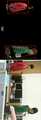
도 12는 본 발명의 실시예들에 따른 영상 감시 방법을 구현한 실험을 통해 이동 물체의 위치를 연속적으로 추적한 결과를 예시한 도면으로서, 각 입력 영상에서 다중 이동 물체를 식별하고, 적어도 두 개의 이동 물체 영역이 겹칠 때와 분리될 경우의 이동 물체 추적 결과를 프레임(frame) 별로 도시하였다. 여기서, 도 12의 (a), (b), (c)는 각각의 이동 물체 영역


도 12에서 알 수 있듯이 본 발명의 실시예들이 제안한 영상 감시 방법은 색상 정보 소실로 인한 이동 물체 식별에 실패하거나, 겹쳐진 경우에도 지속적인 추적이 가능함을 증명한다.As can be seen from FIG. 12, the video surveillance method proposed by the embodiments of the present invention proves that continuous tracking is possible even when the moving object is not identified due to color information loss or overlapped.
상기된 본 발명의 실시예들은, 옵티컬 플로우와 EMD 알고리즘을 이용한 다수의 이동 물체 식별과 칼만 필터를 이용한 추적 알고리즘을 제안하였다. 제안한 영상 감시 시스템은 카메라를 통해 입력된 영상에서 추출된 이동 물체의 인식을 위해 라벨링 기법을 이용하였으며, 인식된 이동 물체의 식별을 위해 옵티컬 플로우 알고리즘과 이동 물체의 색상 기반 히스토그램 정보를 EMD 알고리즘에 적용하는 방법을 제안하였다. 그런 다음, 식별된 이동 물체 영역의 위치를 추적하기 위해 칼만 필터와 이동 물체의 위치 및 이동거리 정보를 융합한 알고리즘을 제안하였다. 이를 통해 제안된 영상 감시 방법은 이동 물체 영역이 오버랩되었을 경우에도 이동 물체의 추적율을 향상시키고, 오버랩 현상에도 불구하고 지속적인 추적이 가능한 영상 감시 체계를 구현하였으며, 모의 실험을 통해 제안된 알고리즘에 대한 응용 가능성을 증명하였다.The above embodiments of the present invention have proposed a tracking algorithm using a plurality of moving object identification and Kalman filter using optical flow and EMD algorithm. The proposed video surveillance system uses a labeling technique to recognize moving objects extracted from images input through a camera. Optical flow algorithms and color - based histogram information of moving objects are applied to the EMD algorithm to identify recognized moving objects. . Then, we propose an algorithm that combines the Kalman filter and the position and movement distance information of the moving object to track the position of the identified moving object area. The proposed video surveillance method improves the tracking rate of the moving object even when the moving object area overlaps and implements the video surveillance system that can keep track of the moving object despite the overlap phenomenon. And proved applicability.
한편, 본 발명은 실시예들은 컴퓨터로 읽을 수 있는 기록 매체에 컴퓨터가 읽을 수 있는 코드로 구현하는 것이 가능하다. 컴퓨터가 읽을 수 있는 기록 매체는 컴퓨터 시스템에 의하여 읽혀질 수 있는 데이터가 저장되는 모든 종류의 기록 장치를 포함한다.Meanwhile, the embodiments of the present invention can be embodied as computer readable codes on a computer readable recording medium. A computer-readable recording medium includes all kinds of recording apparatuses in which data that can be read by a computer system is stored.
컴퓨터가 읽을 수 있는 기록 매체의 예로는 ROM, RAM, CD-ROM, 자기 테이프, 플로피디스크, 광 데이터 저장장치 등을 포함한다. 또한, 컴퓨터가 읽을 수 있는 기록 매체는 네트워크로 연결된 컴퓨터 시스템에 분산되어, 분산 방식으로 컴퓨터가 읽을 수 있는 코드가 저장되고 실행될 수 있다. 그리고 본 발명을 구현하기 위한 기능적인(functional) 프로그램, 코드 및 코드 세그먼트들은 본 발명이 속하는 기술 분야의 프로그래머들에 의하여 용이하게 추론될 수 있다.Examples of the computer-readable recording medium include ROM, RAM, CD-ROM, magnetic tape, floppy disk, optical data storage, and the like. In addition, the computer-readable recording medium may be distributed over network-connected computer systems so that computer readable codes can be stored and executed in a distributed manner. In addition, functional programs, codes, and code segments for implementing the present invention can be easily deduced by programmers skilled in the art to which the present invention belongs.
이상에서 본 발명에 대하여 그 다양한 실시예들을 중심으로 살펴보았다. 본 발명에 속하는 기술 분야에서 통상의 지식을 가진 자는 본 발명이 본 발명의 본질적인 특성에서 벗어나지 않는 범위에서 변형된 형태로 구현될 수 있음을 이해할 수 있을 것이다. 그러므로 개시된 실시예들은 한정적인 관점이 아니라 설명적인 관점에서 고려되어야 한다. 본 발명의 범위는 전술한 설명이 아니라 특허청구범위에 나타나 있으며, 그와 동등한 범위 내에 있는 모든 차이점은 본 발명에 포함된 것으로 해석되어야 할 것이다.The present invention has been described above with reference to various embodiments. It will be understood by those skilled in the art that various changes in form and details may be made therein without departing from the spirit and scope of the invention as defined by the appended claims. Therefore, the disclosed embodiments should be considered in an illustrative rather than a restrictive sense. The scope of the present invention is defined by the appended claims rather than by the foregoing description, and all differences within the scope of equivalents thereof should be construed as being included in the present invention.
100 : 영상 감시 장치
200 : 카메라
10 : 입력부
20 : 프로세서
30 : 메모리100: Video surveillance system
200: camera
10: Input unit
20: Processor
30: Memory
Claims (20)
Translated fromKorean상기 영상 감시 시스템이 상기 이동 물체들이 분포된 영상 영역에 고유 식별자를 부여하는 라벨링(labeling)을 수행하고 라벨링된 이동 물체를 식별하는 단계; 및
상기 영상 감시 시스템이 필터를 이용하여 상기 이동 물체들의 위치를 예측 보정함으로써 이동 물체를 추적하는 단계;를 포함하는 다중 이동 물체의 감시 방법.Extracting at least two moving objects distinguished from the modeled background by modeling a background from an input image of the video surveillance system;
The video surveillance system performs labeling for assigning a unique identifier to an image region where the moving objects are distributed and identifies the labeled moving object; And
And tracking the moving object by predicting and correcting the position of the moving objects using the filter by the video surveillance system.
상기 이동 물체를 추출하는 단계는,
상기 입력된 영상으로부터 확률 모델을 이용하여 전배경(foreground)을 분리하는 단계; 및
이진화를 수행하여 상기 전배경이 분리된 영상으로부터 빛의 반사와 그림자를 제거하는 단계;를 포함하는 다중 이동 물체의 감시 방법.The method according to claim 1,
Wherein the step of extracting the moving object comprises:
Separating a foreground using the probability model from the input image; And
And performing binarization to remove light reflection and shadow from the separated background image.
상기 이동 물체를 추출하는 단계는,
모폴로지(morphology) 연산 중 침식(erosion) 연산을 이용하여 노이즈를 제거하는 단계; 및
상기 침식 연산 과정에서 발생하는 이동 물체 영역의 부분적 손실을 팽창(dilation) 연산을 통해 복원하는 단계;를 더 포함하는 다중 이동 물체의 감시 방법.3. The method of claim 2,
Wherein the step of extracting the moving object comprises:
Removing noise using an erosion operation during a morphology operation; And
And reconstructing a partial loss of the moving object region generated in the erosion calculation process through a dilation operation.
상기 이동 물체를 식별하는 단계는,
추출된 상기 이동 물체들이 포함된 영상의 블롭들(blobs)에 대하여 인접한 화소(pixel)가 연속적으로 분포된 영역을 검색하여 인접한 화소 영역에 고유 식별자를 부여함으로써 라벨링된 영상을 생성하는 단계; 및
시간의 흐름에 따라 서로 다른 복수 개의 시점에 상기 라벨링된 영상 내의 이동 물체로부터 특징점을 추출하여 서로 매칭하고 매칭된 특징점에 기초한 색상 정보를 이용하여 상기 이동 물체 각각의 영역을 식별하는 단계;를 포함하는 다중 이동 물체의 감시 방법.The method according to claim 1,
Wherein identifying the moving object comprises:
Generating a labeled image by searching an area in which neighboring pixels are continuously distributed with respect to blobs of an image including the extracted moving objects and assigning a unique identifier to adjacent pixel areas; And
Extracting feature points from the moving object in the labeled images at a plurality of different time points and identifying the regions of the moving objects using color information based on the matched feature points, A method for monitoring multiple moving objects.
상기 라벨링된 영상을 생성하는 단계는,
상기 영상의 블롭들(blobs)에 대하여 인접한 화소(pixel)가 연속적으로 분포된 영역을 검색하여 인접한 화소 영역에 고유 식별자를 부여하되, 검색된 영역 중 미리 설정된 크기보다 작은 영역을 잡음으로 간주하여 제거하는 것을 특징으로 하는 다중 이동 물체의 감시 방법.5. The method of claim 4,
Wherein the generating the labeled image comprises:
A region in which adjacent pixels are continuously distributed with respect to blobs of the image is searched to give a unique identifier to an adjacent pixel region and a region smaller than a predetermined size among the searched regions is regarded as noise and removed Wherein the method comprises the steps of:
상기 이동 물체 각각의 영역을 식별하는 단계는,
시간의 흐름에 따라 서로 다른 복수 개의 시점에 상기 라벨링된 영상 내의 이동 물체로부터 영상 변화량이 임계값보다 큰 특징점을 추출하고, 추출된 상기 특징점을 서로 매칭하여 매칭된 특징점에 대한 화소 이동량을 산출하되, 색상 정보를 포함하는 히스토그램을 이용하여 상기 서로 다른 복수 개의 시점의 영상으로부터 이동 물체의 유사도를 판별함으로써 수행되는 것을 특징으로 하는 다중 이동 물체의 감시 방법.5. The method of claim 4,
Wherein identifying the region of each of the moving objects comprises:
Extracting a feature point having an image change amount larger than a threshold value from a moving object in the labeled image at a plurality of different viewpoints according to a time, calculating a pixel shift amount for the matched feature point by matching the extracted feature points with each other, And the similarity of the moving object is determined from the images of the plurality of different viewpoints using a histogram including color information.
상기 이동 물체 각각의 영역을 식별하는 단계는,
상기 라벨링된 영상 내의 이동 물체의 주변을 관심 영역으로 설정하고, 설정된 상기 관심 영역에 대해서만 상기 화소 이동량을 실시간으로 산출하는 것을 특징으로 하는 다중 이동 물체의 감시 방법.The method according to claim 6,
Wherein identifying the region of each of the moving objects comprises:
And setting the periphery of the moving object in the labeled image as an area of interest and calculating the pixel shift amount in real time only for the set area of interest.
상기 이동 물체 각각의 영역을 식별하는 단계는,
시간의 흐름에 따라 변화하는 영상의 프레임마다 수행됨으로써 상기 영상 내에 분포된 적어도 둘 이상의 이동 물체를 각각 식별하는 것을 특징으로 하는 다중 이동 물체의 감시 방법.5. The method of claim 4,
Wherein identifying the region of each of the moving objects comprises:
Wherein each of the at least two moving objects is divided into at least two frames, and the at least two moving objects are classified into the plurality of moving objects.
상기 이동 물체 각각의 영역을 식별하는 단계는,
이동 물체의 움직임 변화량이 상대적으로 적은 부분으로서 상기 이동 물체 영역의 무게중심으로부터 가장 가까운 위치에 존재하는 적어도 3개의 특징점을 선택하는 것을 특징으로 하는 다중 이동 물체의 감시 방법.5. The method of claim 4,
Wherein identifying the region of each of the moving objects comprises:
Wherein at least three characteristic points existing at a position closest to a center of gravity of the moving object region are selected as a portion having a relatively small amount of motion variation of the moving object.
상기 이동 물체 각각의 영역을 식별하는 단계는,
비교 대상인 두 개의 히스토그램에 대하여 제 1 히스토그램을 제 2 히스토그램에 일치시키기 위한 화소 정보의 이동량을 산출함으로써 이동 물체 간의 유사도를 판별하는 것을 특징으로 하는 다중 이동 물체의 감시 방법.5. The method of claim 4,
Wherein identifying the region of each of the moving objects comprises:
Wherein the degree of similarity between the moving objects is determined by calculating the amount of movement of the pixel information for matching the first histogram to the second histogram with respect to the two histograms to be compared.
상기 화소 정보의 이동량은 히스토그램에서 옮겨진 색상의 거리와 옮겨진 색상의 양을 승산한 값이며,
상기 색상의 거리는 색상과 채도 값으로 구성된 2차원 히스토그램의 유클리드 거리(Euclidean distance)인 것을 특징으로 하는 다중 이동 물체의 감시 방법.11. The method of claim 10,
The movement amount of the pixel information is a value obtained by multiplying the distance of the color shifted in the histogram by the amount of the transferred color,
Wherein the color distance is an Euclidean distance of a two-dimensional histogram composed of hue and saturation values.
상기 이동 물체를 추적하는 단계는,
칼만 필터(Kalman filter)를 이용하여 상기 이동 물체들의 위치를 예측 보정하되, 적어도 둘 이상의 이동 물체 간의 거리를 산출하여 이동 물체들이 오버랩(overlap)되었는지 여부를 검사하는 것을 특징으로 하는 다중 이동 물체의 감시 방법.The method according to claim 1,
Wherein tracking the moving object comprises:
The method according to any one of claims 1 to 3, wherein the position of the moving objects is estimated and corrected using a Kalman filter, and a distance between at least two moving objects is calculated to check whether moving objects overlap each other. Way.
적어도 둘 이상의 이동 물체가 오버랩(overlap)되었다고 판단된 경우,
상기 이동 물체를 추적하는 단계는,
오버랩 이전까지의 이동 물체 각각의 움직임에 기초하여 오버랩 이후의 이동 물체의 위치를 추정하는 것을 특징으로 하는 다중 이동 물체의 감시 방법.13. The method of claim 12,
If it is determined that at least two moving objects overlap,
Wherein tracking the moving object comprises:
And estimating the position of the moving object after overlap based on the movement of each of the moving objects before overlapping.
상기 이동 물체를 추적하는 단계는,
오버랩 이전 시점에서 보정된 추적 위치와 오버랩 시점의 이동 물체 영역 간의 거리 오차를 이용하여 오버랩 이후의 이동 물체 영역의 위치를 추정하는 것을 특징으로 하는 다중 이동 물체의 감시 방법.14. The method of claim 13,
Wherein tracking the moving object comprises:
Wherein the position of the moving object region after the overlap is estimated using the distance error between the corrected tracking position at the previous point of overlap and the moving object region at the overlap point.
입력된 영상 내에 포함된 적어도 둘 이상의 이동 물체의 움직임을 감시하는 영상 감시 프로그램을 저장하는 메모리; 및
상기 영상 감시 프로그램을 구동하는 적어도 하나의 프로세서;를 포함하되,
상기 메모리에 저장된 영상 감시 프로그램은,
입력된 영상으로부터 배경을 모델링함으로써 상기 모델링된 배경과 구분되는 적어도 둘 이상의 이동 물체를 추출하고, 추출된 상기 이동 물체들이 분포된 영상 영역에 고유 식별자를 부여하는 라벨링(labeling)을 수행하고 라벨링된 이동 물체를 식별하며, 상기 영상 감시 시스템이 필터를 이용하여 상기 이동 물체들의 위치를 예측 보정함으로써 이동 물체를 추적하는 명령어를 포함하는 것을 특징으로 하는 다중 이동 물체 감시 장치.An input unit for receiving an image photographed by the camera;
A memory for storing a video surveillance program for monitoring movement of at least two moving objects included in the input video; And
And at least one processor for driving the video surveillance program,
The video surveillance program stored in the memory,
A background is modeled from the input image to extract at least two moving objects distinguished from the modeled background, labeling is performed to give a unique identifier to the image area in which the moving objects are distributed, Wherein the video surveillance system identifies an object and tracks the moving object by predicting and correcting the position of the moving objects using a filter.
상기 메모리에 저장된 영상 감시 프로그램은,
상기 입력된 영상으로부터 확률 모델을 이용하여 전배경(foreground)을 분리하고, 이진화를 수행하여 상기 전배경이 분리된 영상으로부터 빛의 반사와 그림자를 제거하고, 모폴로지(morphology) 연산 중 침식(erosion) 연산을 이용하여 노이즈를 제거하며, 상기 침식 연산 과정에서 발생하는 이동 물체 영역의 부분적 손실을 팽창(dilation) 연산을 통해 복원함으로써, 상기 이동 물체를 추출하는 것을 특징으로 하는 다중 이동 물체 감시 장치.17. The method of claim 16,
The video surveillance program stored in the memory,
A foreground is separated from the input image by using a probability model, binarization is performed to remove reflection of light and shadow from the separated background image, and erosion during morphology computation, And extracts the moving object by performing a dilation operation on the partial loss of the moving object region generated in the erosion calculation process.
상기 메모리에 저장된 영상 감시 프로그램은,
추출된 상기 이동 물체들이 포함된 영상의 블롭들(blobs)에 대하여 인접한 화소(pixel)가 연속적으로 분포된 영역을 검색하여 인접한 화소 영역에 고유 식별자를 부여함으로써 라벨링된 영상을 생성하고, 시간의 흐름에 따라 서로 다른 복수 개의 시점에 상기 라벨링된 영상 내의 이동 물체로부터 특징점을 추출하여 서로 매칭하고 매칭된 특징점에 기초한 색상 정보를 이용하여 상기 이동 물체 각각의 영역을 식별하는 것을 특징으로 하는 다중 이동 물체 감시 장치.17. The method of claim 16,
The video surveillance program stored in the memory,
A labeled image is generated by searching an area in which adjacent pixels are continuously distributed with respect to blobs of an image including the extracted moving objects and assigning a unique identifier to an adjacent pixel area, Extracts feature points from moving objects in the labeled images at a plurality of different viewpoints and identifies regions of each of the moving objects using color information based on matching feature points, Device.
상기 메모리에 저장된 영상 감시 프로그램은,
칼만 필터(Kalman filter)를 이용하여 상기 이동 물체들의 위치를 예측 보정하되, 적어도 둘 이상의 이동 물체 간의 거리를 산출하여 이동 물체들이 오버랩(overlap)되었는지 여부를 검사하며, 적어도 둘 이상의 이동 물체가 오버랩(overlap)되었다고 판단된 경우, 오버랩 이전까지의 이동 물체 각각의 움직임에 기초하여 오버랩 이후의 이동 물체의 위치를 추정함으로써, 상기 이동 물체를 추적하는 것을 특징으로 하는 다중 이동 물체 감시 장치.17. The method of claim 16,
The video surveillance program stored in the memory,
A Kalman filter is used to predict and correct the position of the moving objects and to check whether or not the moving objects overlap with each other by calculating a distance between at least two moving objects, overlapping, the moving object is tracked by estimating the position of the moving object after overlap based on the movement of each of the moving objects before overlapping.
상기 메모리에 저장된 영상 감시 프로그램은,
오버랩 이전 시점에서 보정된 추적 위치와 오버랩 시점의 이동 물체 영역 간의 거리 오차를 이용하여 오버랩 이후의 이동 물체 영역의 위치를 추정하는 것을 특징으로 하는 다중 이동 물체 감시 장치.20. The method of claim 19,
The video surveillance program stored in the memory,
Wherein the position of the moving object region after the overlap is estimated by using a distance error between the corrected tracking position at the previous point of overlap and the moving object region at the overlap point.
Priority Applications (1)
| Application Number | Priority Date | Filing Date | Title |
|---|---|---|---|
| KR1020150080552AKR101764845B1 (en) | 2015-06-08 | 2015-06-08 | A video surveillance apparatus for removing overlap and tracking multiple moving objects and method thereof |
Applications Claiming Priority (1)
| Application Number | Priority Date | Filing Date | Title |
|---|---|---|---|
| KR1020150080552AKR101764845B1 (en) | 2015-06-08 | 2015-06-08 | A video surveillance apparatus for removing overlap and tracking multiple moving objects and method thereof |
Publications (2)
| Publication Number | Publication Date |
|---|---|
| KR20160144149Atrue KR20160144149A (en) | 2016-12-16 |
| KR101764845B1 KR101764845B1 (en) | 2017-08-03 |
Family
ID=57735879
Family Applications (1)
| Application Number | Title | Priority Date | Filing Date |
|---|---|---|---|
| KR1020150080552AActiveKR101764845B1 (en) | 2015-06-08 | 2015-06-08 | A video surveillance apparatus for removing overlap and tracking multiple moving objects and method thereof |
Country Status (1)
| Country | Link |
|---|---|
| KR (1) | KR101764845B1 (en) |
Cited By (15)
| Publication number | Priority date | Publication date | Assignee | Title |
|---|---|---|---|---|
| KR101868103B1 (en)* | 2017-07-12 | 2018-06-18 | 군산대학교 산학협력단 | A video surveillance apparatus for identification and tracking multiple moving objects and method thereof |
| KR101863662B1 (en)* | 2017-01-25 | 2018-06-29 | 문영실 | Smart factory operation system using camera |
| KR20180074836A (en)* | 2016-12-23 | 2018-07-04 | 전자부품연구원 | A position recognition system and method for a plurality of ground vehicle, and ground vehicle and control device thereof |
| KR20180074835A (en)* | 2016-12-23 | 2018-07-04 | 전자부품연구원 | A position recognition system using the power of the light emitiing device for a plurality of ground vehicle |
| WO2018138697A1 (en)* | 2017-01-30 | 2018-08-02 | Virtual Innovation Center Srl | Method of generating tracking information for automatic aiming and related automatic aiming system for the video acquisition of sports events, particularly soccer matches with 5, 7 or 11 players |
| KR20180093402A (en)* | 2017-02-13 | 2018-08-22 | 한국전자통신연구원 | System and method for tracking multiple objects |
| WO2019004530A1 (en)* | 2017-06-29 | 2019-01-03 | 링크플로우 주식회사 | Method for removing object to be processed from image and device for performing method |
| KR102019301B1 (en)* | 2018-04-24 | 2019-09-06 | 군산대학교 산학협력단 | A video surveillance apparatus for detecting agro-livestock theft and method thereof |
| KR102052110B1 (en)* | 2018-05-24 | 2019-12-04 | 군산대학교 산학협력단 | A video surveillance apparatus for detecting agro-livestock theft based on deep learning and method thereof |
| KR20190134916A (en)* | 2018-05-11 | 2019-12-05 | 초록소프트 주식회사 | Method and apparatus for collecting floating population data on realtime road image |
| KR20200078098A (en)* | 2018-12-21 | 2020-07-01 | 인천대학교 산학협력단 | Method for tracking a person using an overhead camera |
| KR102194947B1 (en)* | 2019-08-12 | 2020-12-24 | 고려대학교 산학협력단 | Image Analysis Method and Computer Readable Storage Medium |
| KR20210133562A (en)* | 2020-04-29 | 2021-11-08 | 군산대학교산학협력단 | Method for multiple moving object tracking using similarity between probability distributions and object tracking system thereof |
| KR20220049389A (en)* | 2020-10-14 | 2022-04-21 | (주)유디피 | Apparatus and method for tracking object using skeleton analysis |
| WO2024158073A1 (en)* | 2023-01-27 | 2024-08-02 | 라쿠텐 심포니 주식회사 | Determination of similarity between images using learning model |
Citations (1)
| Publication number | Priority date | Publication date | Assignee | Title |
|---|---|---|---|---|
| KR102010007B1 (en) | 2015-03-12 | 2019-08-12 | 지디 미디어 인바이런먼트 어플라이언스즈 엠에프지. 컴퍼니 리미티드 | Diffusers, centrifugal compression power systems, and bladeless fans |
Family Cites Families (1)
| Publication number | Priority date | Publication date | Assignee | Title |
|---|---|---|---|---|
| KR101508310B1 (en)* | 2014-04-10 | 2015-04-07 | 군산대학교산학협력단 | Apparatus and method for tracking multiple moving objects in video surveillance system |
- 2015
- 2015-06-08KRKR1020150080552Apatent/KR101764845B1/enactiveActive
Patent Citations (1)
| Publication number | Priority date | Publication date | Assignee | Title |
|---|---|---|---|---|
| KR102010007B1 (en) | 2015-03-12 | 2019-08-12 | 지디 미디어 인바이런먼트 어플라이언스즈 엠에프지. 컴퍼니 리미티드 | Diffusers, centrifugal compression power systems, and bladeless fans |
Cited By (16)
| Publication number | Priority date | Publication date | Assignee | Title |
|---|---|---|---|---|
| KR20180074836A (en)* | 2016-12-23 | 2018-07-04 | 전자부품연구원 | A position recognition system and method for a plurality of ground vehicle, and ground vehicle and control device thereof |
| KR20180074835A (en)* | 2016-12-23 | 2018-07-04 | 전자부품연구원 | A position recognition system using the power of the light emitiing device for a plurality of ground vehicle |
| KR101863662B1 (en)* | 2017-01-25 | 2018-06-29 | 문영실 | Smart factory operation system using camera |
| WO2018138697A1 (en)* | 2017-01-30 | 2018-08-02 | Virtual Innovation Center Srl | Method of generating tracking information for automatic aiming and related automatic aiming system for the video acquisition of sports events, particularly soccer matches with 5, 7 or 11 players |
| KR20180093402A (en)* | 2017-02-13 | 2018-08-22 | 한국전자통신연구원 | System and method for tracking multiple objects |
| US11076096B2 (en) | 2017-06-29 | 2021-07-27 | Linkflow Co., Ltd | Method for removing object to be processed from image and device for performing method |
| WO2019004530A1 (en)* | 2017-06-29 | 2019-01-03 | 링크플로우 주식회사 | Method for removing object to be processed from image and device for performing method |
| KR101868103B1 (en)* | 2017-07-12 | 2018-06-18 | 군산대학교 산학협력단 | A video surveillance apparatus for identification and tracking multiple moving objects and method thereof |
| KR102019301B1 (en)* | 2018-04-24 | 2019-09-06 | 군산대학교 산학협력단 | A video surveillance apparatus for detecting agro-livestock theft and method thereof |
| KR20190134916A (en)* | 2018-05-11 | 2019-12-05 | 초록소프트 주식회사 | Method and apparatus for collecting floating population data on realtime road image |
| KR102052110B1 (en)* | 2018-05-24 | 2019-12-04 | 군산대학교 산학협력단 | A video surveillance apparatus for detecting agro-livestock theft based on deep learning and method thereof |
| KR20200078098A (en)* | 2018-12-21 | 2020-07-01 | 인천대학교 산학협력단 | Method for tracking a person using an overhead camera |
| KR102194947B1 (en)* | 2019-08-12 | 2020-12-24 | 고려대학교 산학협력단 | Image Analysis Method and Computer Readable Storage Medium |
| KR20210133562A (en)* | 2020-04-29 | 2021-11-08 | 군산대학교산학협력단 | Method for multiple moving object tracking using similarity between probability distributions and object tracking system thereof |
| KR20220049389A (en)* | 2020-10-14 | 2022-04-21 | (주)유디피 | Apparatus and method for tracking object using skeleton analysis |
| WO2024158073A1 (en)* | 2023-01-27 | 2024-08-02 | 라쿠텐 심포니 주식회사 | Determination of similarity between images using learning model |
Also Published As
| Publication number | Publication date |
|---|---|
| KR101764845B1 (en) | 2017-08-03 |
Similar Documents
| Publication | Publication Date | Title |
|---|---|---|
| KR101764845B1 (en) | A video surveillance apparatus for removing overlap and tracking multiple moving objects and method thereof | |
| KR101995107B1 (en) | Method and system for artificial intelligence based video surveillance using deep learning | |
| Elhabian et al. | Moving object detection in spatial domain using background removal techniques-state-of-art | |
| Ojha et al. | Image processing techniques for object tracking in video surveillance-A survey | |
| Portmann et al. | People detection and tracking from aerial thermal views | |
| CN105469029B (en) | System and method for object re-identification | |
| US7957560B2 (en) | Unusual action detector and abnormal action detecting method | |
| US8855363B2 (en) | Efficient method for tracking people | |
| KR101868103B1 (en) | A video surveillance apparatus for identification and tracking multiple moving objects and method thereof | |
| US20090041297A1 (en) | Human detection and tracking for security applications | |
| KR101653278B1 (en) | Face tracking system using colar-based face detection method | |
| Shukla et al. | Moving object tracking of vehicle detection: A concise review | |
| KR101472674B1 (en) | Method and apparatus for video surveillance based on detecting abnormal behavior using extraction of trajectories from crowd in images | |
| US20150049906A1 (en) | Human image tracking system, and human image detection and human image tracking methods thereof | |
| Zang et al. | Object classification and tracking in video surveillance | |
| Fradi et al. | Spatial and temporal variations of feature tracks for crowd behavior analysis | |
| KR102019301B1 (en) | A video surveillance apparatus for detecting agro-livestock theft and method thereof | |
| Arif et al. | A comprehensive review of vehicle detection techniques under varying moving cast shadow conditions using computer vision and deep learning | |
| Arsic et al. | Applying multi layer homography for multi camera person tracking | |
| KR101406334B1 (en) | System and method for tracking multiple object using reliability and delayed decision | |
| WO2012141663A1 (en) | A method for individual tracking of multiple objects | |
| Angelo | A novel approach on object detection and tracking using adaptive background subtraction method | |
| Cancela et al. | Hierarchical framework for robust and fast multiple-target tracking in surveillance scenarios | |
| US20080198237A1 (en) | System and method for adaptive pixel segmentation from image sequences | |
| Denman et al. | Multi-spectral fusion for surveillance systems |
Legal Events
| Date | Code | Title | Description |
|---|---|---|---|
| A201 | Request for examination | ||
| PA0109 | Patent application | St.27 status event code:A-0-1-A10-A12-nap-PA0109 | |
| PA0201 | Request for examination | St.27 status event code:A-1-2-D10-D11-exm-PA0201 | |
| R18-X000 | Changes to party contact information recorded | St.27 status event code:A-3-3-R10-R18-oth-X000 | |
| E902 | Notification of reason for refusal | ||
| PE0902 | Notice of grounds for rejection | St.27 status event code:A-1-2-D10-D21-exm-PE0902 | |
| T11-X000 | Administrative time limit extension requested | St.27 status event code:U-3-3-T10-T11-oth-X000 | |
| T11-X000 | Administrative time limit extension requested | St.27 status event code:U-3-3-T10-T11-oth-X000 | |
| T11-X000 | Administrative time limit extension requested | St.27 status event code:U-3-3-T10-T11-oth-X000 | |
| T11-X000 | Administrative time limit extension requested | St.27 status event code:U-3-3-T10-T11-oth-X000 | |
| PG1501 | Laying open of application | St.27 status event code:A-1-1-Q10-Q12-nap-PG1501 | |
| E13-X000 | Pre-grant limitation requested | St.27 status event code:A-2-3-E10-E13-lim-X000 | |
| P11-X000 | Amendment of application requested | St.27 status event code:A-2-2-P10-P11-nap-X000 | |
| P13-X000 | Application amended | St.27 status event code:A-2-2-P10-P13-nap-X000 | |
| E902 | Notification of reason for refusal | ||
| PE0902 | Notice of grounds for rejection | St.27 status event code:A-1-2-D10-D21-exm-PE0902 | |
| P11-X000 | Amendment of application requested | St.27 status event code:A-2-2-P10-P11-nap-X000 | |
| P13-X000 | Application amended | St.27 status event code:A-2-2-P10-P13-nap-X000 | |
| E701 | Decision to grant or registration of patent right | ||
| PE0701 | Decision of registration | St.27 status event code:A-1-2-D10-D22-exm-PE0701 | |
| PR0701 | Registration of establishment | St.27 status event code:A-2-4-F10-F11-exm-PR0701 | |
| PR1002 | Payment of registration fee | St.27 status event code:A-2-2-U10-U11-oth-PR1002 Fee payment year number:1 | |
| PG1601 | Publication of registration | St.27 status event code:A-4-4-Q10-Q13-nap-PG1601 | |
| PN2301 | Change of applicant | St.27 status event code:A-5-5-R10-R11-asn-PN2301 | |
| PN2301 | Change of applicant | St.27 status event code:A-5-5-R10-R14-asn-PN2301 | |
| P14-X000 | Amendment of ip right document requested | St.27 status event code:A-5-5-P10-P14-nap-X000 | |
| P14-X000 | Amendment of ip right document requested | St.27 status event code:A-5-5-P10-P14-nap-X000 | |
| P22-X000 | Classification modified | St.27 status event code:A-4-4-P10-P22-nap-X000 | |
| R18-X000 | Changes to party contact information recorded | St.27 status event code:A-5-5-R10-R18-oth-X000 | |
| R18-X000 | Changes to party contact information recorded | St.27 status event code:A-5-5-R10-R18-oth-X000 | |
| PN2301 | Change of applicant | St.27 status event code:A-5-5-R10-R11-asn-PN2301 | |
| PN2301 | Change of applicant | St.27 status event code:A-5-5-R10-R14-asn-PN2301 | |
| P14-X000 | Amendment of ip right document requested | St.27 status event code:A-5-5-P10-P14-nap-X000 | |
| P16-X000 | Ip right document amended | St.27 status event code:A-5-5-P10-P16-nap-X000 | |
| Q16-X000 | A copy of ip right certificate issued | St.27 status event code:A-4-4-Q10-Q16-nap-X000 | |
| R18-X000 | Changes to party contact information recorded | St.27 status event code:A-5-5-R10-R18-oth-X000 | |
| P14-X000 | Amendment of ip right document requested | St.27 status event code:A-5-5-P10-P14-nap-X000 | |
| P14-X000 | Amendment of ip right document requested | St.27 status event code:A-5-5-P10-P14-nap-X000 | |
| R18-X000 | Changes to party contact information recorded | St.27 status event code:A-5-5-R10-R18-oth-X000 | |
| PR1001 | Payment of annual fee | St.27 status event code:A-4-4-U10-U11-oth-PR1001 Fee payment year number:4 | |
| PR1001 | Payment of annual fee | St.27 status event code:A-4-4-U10-U11-oth-PR1001 Fee payment year number:5 | |
| PR1001 | Payment of annual fee | St.27 status event code:A-4-4-U10-U11-oth-PR1001 Fee payment year number:6 | |
| P22-X000 | Classification modified | St.27 status event code:A-4-4-P10-P22-nap-X000 | |
| R18-X000 | Changes to party contact information recorded | St.27 status event code:A-5-5-R10-R18-oth-X000 | |
| PR1001 | Payment of annual fee | St.27 status event code:A-4-4-U10-U11-oth-PR1001 Fee payment year number:7 | |
| S20-X000 | Security interest recorded | St.27 status event code:A-4-4-S10-S20-lic-X000 | |
| R18-X000 | Changes to party contact information recorded | St.27 status event code:A-5-5-R10-R18-oth-X000 | |
| PN2301 | Change of applicant | St.27 status event code:A-5-5-R10-R13-asn-PN2301 St.27 status event code:A-5-5-R10-R11-asn-PN2301 | |
| PN2301 | Change of applicant | St.27 status event code:A-5-5-R10-R13-asn-PN2301 St.27 status event code:A-5-5-R10-R11-asn-PN2301 | |
| R18-X000 | Changes to party contact information recorded | St.27 status event code:A-5-5-R10-R18-oth-X000 | |
| R18-X000 | Changes to party contact information recorded | St.27 status event code:A-5-5-R10-R18-oth-X000 | |
| P14-X000 | Amendment of ip right document requested | St.27 status event code:A-5-5-P10-P14-nap-X000 | |
| R18-X000 | Changes to party contact information recorded | St.27 status event code:A-5-5-R10-R18-oth-X000 |