KR20160140275A - ELECTRONIC DEVICE AND METHOD FOR DYNAMIC POWER CONTROL - Google Patents
ELECTRONIC DEVICE AND METHOD FOR DYNAMIC POWER CONTROLDownload PDFInfo
- Publication number
- KR20160140275A KR20160140275AKR1020150076705AKR20150076705AKR20160140275AKR 20160140275 AKR20160140275 AKR 20160140275AKR 1020150076705 AKR1020150076705 AKR 1020150076705AKR 20150076705 AKR20150076705 AKR 20150076705AKR 20160140275 AKR20160140275 AKR 20160140275A
- Authority
- KR
- South Korea
- Prior art keywords
- power
- voltage
- input
- power source
- port
- Prior art date
- Legal status (The legal status is an assumption and is not a legal conclusion. Google has not performed a legal analysis and makes no representation as to the accuracy of the status listed.)
- Withdrawn
Links
Images


Classifications
- H—ELECTRICITY
- H02—GENERATION; CONVERSION OR DISTRIBUTION OF ELECTRIC POWER
- H02J—CIRCUIT ARRANGEMENTS OR SYSTEMS FOR SUPPLYING OR DISTRIBUTING ELECTRIC POWER; SYSTEMS FOR STORING ELECTRIC ENERGY
- H02J1/00—Circuit arrangements for DC mains or DC distribution networks
- H02J1/10—Parallel operation of DC sources
- H02J1/12—Parallel operation of DC generators with converters, e.g. with mercury-arc rectifier
- H—ELECTRICITY
- H02—GENERATION; CONVERSION OR DISTRIBUTION OF ELECTRIC POWER
- H02J—CIRCUIT ARRANGEMENTS OR SYSTEMS FOR SUPPLYING OR DISTRIBUTING ELECTRIC POWER; SYSTEMS FOR STORING ELECTRIC ENERGY
- H02J1/00—Circuit arrangements for DC mains or DC distribution networks
- H02J1/10—Parallel operation of DC sources
- H02J1/102—Parallel operation of DC sources being switching converters
- H02J7/0055—
- G—PHYSICS
- G06—COMPUTING OR CALCULATING; COUNTING
- G06F—ELECTRIC DIGITAL DATA PROCESSING
- G06F1/00—Details not covered by groups G06F3/00 - G06F13/00 and G06F21/00
- G06F1/26—Power supply means, e.g. regulation thereof
- G—PHYSICS
- G06—COMPUTING OR CALCULATING; COUNTING
- G06F—ELECTRIC DIGITAL DATA PROCESSING
- G06F1/00—Details not covered by groups G06F3/00 - G06F13/00 and G06F21/00
- G06F1/26—Power supply means, e.g. regulation thereof
- G06F1/263—Arrangements for using multiple switchable power supplies, e.g. battery and AC
- H—ELECTRICITY
- H02—GENERATION; CONVERSION OR DISTRIBUTION OF ELECTRIC POWER
- H02J—CIRCUIT ARRANGEMENTS OR SYSTEMS FOR SUPPLYING OR DISTRIBUTING ELECTRIC POWER; SYSTEMS FOR STORING ELECTRIC ENERGY
- H02J2207/00—Indexing scheme relating to details of circuit arrangements for charging or depolarising batteries or for supplying loads from batteries
- H02J2207/40—Indexing scheme relating to details of circuit arrangements for charging or depolarising batteries or for supplying loads from batteries adapted for charging from various sources, e.g. AC, DC or multivoltage
- H—ELECTRICITY
- H02—GENERATION; CONVERSION OR DISTRIBUTION OF ELECTRIC POWER
- H02J—CIRCUIT ARRANGEMENTS OR SYSTEMS FOR SUPPLYING OR DISTRIBUTING ELECTRIC POWER; SYSTEMS FOR STORING ELECTRIC ENERGY
- H02J2310/00—The network for supplying or distributing electric power characterised by its spatial reach or by the load
- H02J2310/10—The network having a local or delimited stationary reach
- H02J2310/18—The network being internal to a power source or plant
- H—ELECTRICITY
- H02—GENERATION; CONVERSION OR DISTRIBUTION OF ELECTRIC POWER
- H02J—CIRCUIT ARRANGEMENTS OR SYSTEMS FOR SUPPLYING OR DISTRIBUTING ELECTRIC POWER; SYSTEMS FOR STORING ELECTRIC ENERGY
- H02J7/00—Circuit arrangements for charging or depolarising batteries or for supplying loads from batteries
Landscapes
- Engineering & Computer Science (AREA)
- Power Engineering (AREA)
- Theoretical Computer Science (AREA)
- Power Sources (AREA)
- Physics & Mathematics (AREA)
- General Engineering & Computer Science (AREA)
- General Physics & Mathematics (AREA)
- Charge And Discharge Circuits For Batteries Or The Like (AREA)
Abstract
Translated fromKorean
Description
Translated fromKorean본 발명의 다양한 실시 예는 전원 입출력의 동적 제어에 관한 것이다.Various embodiments of the present invention are directed to dynamic control of power input and output.
일반적으로 노트 PC(Note PC), 랩탑(Laptop), 타블렛 PC(Tablet PC), 스마트폰(Smartphone)과 같은 전자 장치는 폼 팩터(Form Factor) 측면에서 이동성(Mobility)을 향상시키기 위해 점점 얇고 가벼워지고 있다. 이러한 전자 장치는 전원 입력을 위한 단일 전원 입력 포트를 구비하거나 USB 포트와 같이 데이터 통신 및 전원 입출력을 위한 하나 이상의 입출력 포트를 구비할 수 있다.Generally, electronic devices such as a Note PC, a Laptop, a Tablet PC, and a Smartphone are becoming thinner and lighter in order to improve mobility in terms of form factor ought. Such an electronic device may have a single power input port for power input or one or more input / output ports for data communication and power input / output such as a USB port.
이러한 경향에 따라, 최근 USB-IF(USB Implementers Forum)에서는 상하 구별없이 장착 가능하도록 설계되고, 고속의 소형화된 새로운 USB 타입-C 커넥터(USB Type-C Connector) 및 케이블 규격을 표준화하였다. 이러한 USB 타입-C 커넥터 및 케이블은 최대 100W 급의 전력 공급을 가능하도록 USB PD(Power Delivery) 규격을 지원한다.In accordance with this tendency, the USB Implementers Forum (USB-IF) recently standardized a new USB Type-C connector and a cable standard that are designed to be mountable without distinction. These USB type-C connectors and cables support the USB Power Delivery (PD) specification to enable power up to 100W.
전자 장치의 전원 입력 포트에 대한 표준화가 추진되면서 전자 장치의 전원 공급 장치(예, AC/DC 어댑터)가 휴대성, 사용성, 설계 비용에 따라 USB 타입-C 형태로 구현될 가능성이 높아지고 있다.As the standardization of the power input port of the electronic device is promoted, the power supply device of the electronic device (for example, AC / DC adapter) is increasingly realized as a USB type-C type according to portability, usability and design cost.
상기와 같이 종래의 전자 장치는 단일 전원 입력 포트를 통해서 전원이 입력되거나 하나 이상의 입출력 포트를 통해서 데이터 통신 및 전원 입출력이 가능하다.As described above, the conventional electronic device is capable of inputting power through a single power input port or data communication and power input / output through one or more input / output ports.
하지만 종래의 전자 장치는 하나 이상의 입출력 포트를 구비하더라도 전자 장치에서 필요로 하는 전력량에 따라 주로 외부의 단일 전원 입력 포트를 통해서 전원을 공급받기 때문에 전원 공급 장치의 크기가 커지고, 무게가 증가한다는 불편함이 있다.However, since the conventional electronic device is supplied with power mainly through an external single power input port according to the amount of power required by the electronic device even though the device has one or more input / output ports, the size of the power supply device increases and the weight increases. .
따라서, 전자 장치의 휴대성 및 성능을 높이고, 사용 시간을 증가시키기 위해 전원 입출력의 효율적인 설계 및 제어가 필요하다.Therefore, efficient design and control of the power input / output is required to increase the portability and performance of the electronic device and increase the use time.
본 발명의 다양한 실시 예에서는 동적 전원 제어를 위한 전자 장치 및 그 방법을 제공한다.Various embodiments of the present invention provide an electronic device and method for dynamic power control.
상술한 바를 달성하기 위해 본 발명의 다양한 실시 예에 따르면 동적 전원 제어를 위한 전자 장치는 전원 입력이 가능한 적어도 제1 포트 및 제2 포트를 포함하는 복수의 포트들; 상기 제1 포트에 연결되는 제1 외부 장치로부터 공급되는 제1 전원을 변환하는 제1 전원 변환부 및 상기 제2 포트에 연결되는 제2 외부 장치로부터 공급되는 제2 전원을 변환하는 제2 전원 변환부를 포함하는 전원 제어부; 및 상기 제1 전원과 상기 제2 전원을 가산하여 타겟 장치에 전원이 공급되도록 상기 전원 제어부를 제어하는 제어부를 포함할 수 있다.According to various embodiments of the present invention, an electronic device for dynamic power control includes a plurality of ports including at least a first port and a second port capable of power input; A first power conversion unit for converting a first power supplied from a first external device connected to the first port and a second power conversion unit for converting a second power supplied from a second external device connected to the second port, A power control unit including a power supply unit; And a controller for controlling the power controller to supply power to the target device by adding the first power source and the second power source.
본 발명의 다양한 실시 예들에 따르면 동적 전원 제어를 위한 전자 장치에 대한 방법은 전원 입력이 가능한 제2 포트에 연결되는 제2 외부 장치로부터 제2 전원을 공급받는 동작; 상기 제1 전원 및 상기 제2 전원을 변환하는 동작; 및 상기 제1 전원과 상기 제2 전원을 가산하여 타겟 장치에 전원을 공급하는 동작;을 포함할 수 있다.According to various embodiments of the present invention, a method for an electronic device for dynamic power control comprises: receiving a second power from a second external device coupled to a second port capable of power input; Converting the first power source and the second power source; And an operation of supplying power to the target device by adding the first power source and the second power source.
본 발명의 다양한 실시 예에서는 USB 전원 입출력 포트 및 전원 포트를 통해서 입력된 전원을 가산하여 전자 장치에서 필요로 하는 대용량의 전원을 공급할 수 있다.In various embodiments of the present invention, the power input through the USB power input / output port and the power port can be added to supply a large amount of power required by the electronic device.
또한 본 발명의 다양한 실시 예에서는 다수의 소형 랩탑, 태블릿 PC 또는 스마트폰과 같은 외부 장치로부터 입력되는 전원을 결합하여 전자 장치의 최대 성능을 위한 고용량의 전원을 공급하거나 전자 장치의 성능 또는 기능을 제한하지 않은 상태에서 전원을 공급받아 전자 장치에 구비된 배터리 충전 속도를 개선시킬 수 있다.Also, in various embodiments of the present invention, power supplied from an external device such as a number of small laptops, tablet PCs, or smart phones may be combined to provide a high capacity power supply for maximum performance of the electronic device, The battery charging speed of the electronic device can be improved.
뿐만 아니라 본 발명의 다양한 실시 예에서는 대용량의 AC/DC 어댑터를 이용하지 않더라도 타입-C 형태의 USB 전원 입출력 포트를 이용하여 언제 어디서나 쉽게 필요한 대용량의 전원을 확보할 수 있기 때문에 전자 장치의 휴대성을 향상시킬 수 있고, 설계 비용을 절감할 수 있다.In addition, in various embodiments of the present invention, even if a large-capacity AC / DC adapter is not used, a large-capacity power source can be easily secured at any time by using a type-C type USB power input / output port. And the design cost can be reduced.
도 1은 다양한 실시 예에 따른, 전자 장치를 포함하는 네트워크 환경(100)를 도시한다.
도 2는 다양한 실시 예에 따른 전자 장치와 다수의 외부 장치를 포함하는 전원 입출력을 위한 시스템의 구성도이다.
도 3은 다양한 실시 예에 따른 전자 장치의 세부 구성도이다.
도 4는 다양한 실시 예에 따라 DC 전원 포트에 대응하는 제1 전원 변환부의 세부 구성도이다.
도 5는 다양한 실시 예에 따라 제1 USB 입출력 포트에 대응하는 제2 전원 변환부의 세부 구성도이다.
도 6은 다양한 실시 예에 따라 USB 출력 포트에 대응하는 전원 변환부의 세부 구성도이다.
도 7은 다양한 실시 예에 따라 도 4, 도 5, 도 6의 전원 변환부들을 적용한 휴대 전자 장치의 세부 구성도이다.
도 8은 다양한 실시 예에 따라 전원 입출력 시 제어부에서 전원 입출력을 처리하는 과정을 설명하기 위한 흐름도들이다.
도 9는 다양한 실시 예에 따라 전자 장치가 동작하지 않은 상태에서 전원 입출력 시 제어부에서 전원 입출력을 처리하는 과정을 설명하기 위한 흐름도이다.1 illustrates a
2 is a configuration diagram of a system for power input / output including an electronic device and a plurality of external devices according to various embodiments.
3 is a detailed configuration diagram of an electronic device according to various embodiments.
4 is a detailed configuration diagram of a first power conversion unit corresponding to a DC power port according to various embodiments.
5 is a detailed configuration diagram of a second power conversion unit corresponding to a first USB input / output port according to various embodiments.
6 is a detailed configuration diagram of a power conversion unit corresponding to a USB output port according to various embodiments.
FIG. 7 is a detailed configuration diagram of a portable electronic device to which the power conversion units of FIGS. 4, 5, and 6 are applied according to various embodiments.
FIG. 8 is a flowchart illustrating a process of processing a power input / output in a controller during power input / output according to various embodiments.
FIG. 9 is a flowchart illustrating a process of processing power input / output by the control unit during power input / output in a state where the electronic device is not operated according to various embodiments.
이하, 본 문서의 다양한 실시 예가 첨부된 도면을 참조하여 기재된다. 그러나, 이는 본 문서에 기재된 기술을 특정한 실시 형태에 대해 한정하려는 것이 아니며, 본 문서의 실시예의 다양한 변경(modifications), 균등물(equivalents), 및/또는 대체물(alternatives)을 포함하는 것으로 이해되어야 한다. 도면의 설명과 관련하여, 유사한 구성요소에 대해서는 유사한 참조부호가 사용될 수 있다.Hereinafter, various embodiments of the present document will be described with reference to the accompanying drawings. It should be understood, however, that this invention is not intended to be limited to the particular embodiments described herein but includes various modifications, equivalents, and / or alternatives of the embodiments of this document . In connection with the description of the drawings, like reference numerals may be used for similar components.
본 문서에서,"가진다," "가질 수 있다," "포함한다," 또는 "포함할 수 있다" 등의 표현은 해당 특징(예: 수치, 기능, 동작, 또는 부품 등의 구성요소)의 존재를 가리키며, 추가적인 특징의 존재를 배제하지 않는다.In this document, the expressions "having," " having, "" comprising," or &Quot;, and does not exclude the presence of additional features.
본 문서에서,"A 또는 B," "A 또는/및 B 중 적어도 하나," 또는 "A 또는/및 B 중 하나 또는 그 이상" 등의 표현은 함께 나열된 항목들의 모든 가능한 조합을 포함할 수 있다. 예를 들면, "A 또는 B," "A 및 B 중 적어도 하나," 또는 "A 또는 B 중 적어도 하나"는, (1) 적어도 하나의 A를 포함, (2) 적어도 하나의 B 를 포함, 또는(3) 적어도 하나의 A 및 적어도 하나의 B 모두를 포함하는 경우를 모두 지칭할 수 있다.In this document, the expressions "A or B," "at least one of A or / and B," or "one or more of A and / or B," etc. may include all possible combinations of the listed items . For example, "A or B," "at least one of A and B," or "at least one of A or B" includes (1) at least one A, (2) Or (3) at least one A and at least one B all together.
본 문서에서 사용된 "제1," "제2," "첫째," 또는 "둘째," 등의 표현들은 다양한 구성요소들을, 순서 및/또는 중요도에 상관없이 수식할 수 있고, 한 구성요소를 다른 구성요소와 구분하기 위해 사용될 뿐 해당 구성요소들을 한정하지 않는다. 예를 들면, 제 1 사용자기기와 제 2 사용자기기는, 순서 또는 중요도와 무관하게, 서로 다른 사용자기기를 나타낼 수 있다. 예를 들면, 본 문서에 기재된 권리범위를 벗어나지 않으면서 제 1 구성요소는 제 2 구성요소로 명명될 수 있고, 유사하게 제 2 구성요소도 제 1 구성요소로 바꾸어 명명될 수 있다.As used herein, the terms "first," "second," "first," or "second," and the like may denote various components, regardless of their order and / or importance, But is used to distinguish it from other components and does not limit the components. For example, the first user equipment and the second user equipment may represent different user equipment, regardless of order or importance. For example, without departing from the scope of the rights described in this document, the first component can be named as the second component, and similarly the second component can also be named as the first component.
어떤 구성요소(예: 제 1 구성요소)가 다른 구성요소(예: 제 2 구성요소)에 "(기능적으로 또는 통신적으로) 연결되어((operatively or communicatively) coupled with/to)" 있다거나 "접속되어(connected to)" 있다고 언급된 때에는, 상기 어떤 구성요소가 상기 다른 구성요소에 직접적으로 연결되거나, 다른 구성요소(예: 제 3 구성요소)를 통하여 연결될 수 있다고 이해되어야 할 것이다. 반면에, 어떤 구성요소(예: 제 1 구성요소)가 다른 구성요소(예: 제 2 구성요소)에 "직접 연결되어" 있다거나 "직접 접속되어" 있다고 언급된 때에는, 상기 어떤 구성요소와 상기 다른 구성요소 사이에 다른 구성요소(예: 제 3 구성요소)가 존재하지 않는 것으로 이해될 수 있다.(Or functionally or communicatively) coupled with / to "another component (eg, a second component), or a component (eg, a second component) Quot; connected to ", it is to be understood that any such element may be directly connected to the other element or may be connected through another element (e.g., a third element). On the other hand, when it is mentioned that a component (e.g., a first component) is "directly connected" or "directly connected" to another component (e.g., a second component) It can be understood that there is no other component (e.g., a third component) between other components.
본 문서에서 사용된 표현 "~하도록 구성된(또는 설정된)(configured to)"은 상황에 따라, 예를 들면, "~에 적합한(suitable for)," "~하는 능력을 가지는(having the capacity to)," "~하도록 설계된(designed to)," "~하도록 변경된(adapted to)," "~하도록 만들어진(made to)," 또는 "~ 를 할 수 있는(capable of)"과 바꾸어 사용될 수 있다. 용어 "~하도록 구성된(또는 설정된)"은 하드웨어적으로 "특별히 설계된(specifically designed to)" 것만을 반드시 의미하지 않을 수 있다. 대신, 어떤 상황에서는, "~하도록 구성된 장치"라는 표현은, 그 장치가 다른 장치 또는 부품들과 함께 "~할 수 있는" 것을 의미할 수 있다. 예를 들면, 문구 "A, B, 및 C를 수행하도록 구성된(또는 설정된)프로세서"는 해당 동작을 수행하기 위한 전용 프로세서(예: 임베디드 프로세서), 또는 메모리 장치에 저장된 하나 이상의 소프트웨어 프로그램들을 실행함으로써, 해당 동작들을 수행할 수 있는 범용 프로세서(generic-purpose processor)(예: CPU 또는 application processor)를 의미할 수 있다.As used herein, the phrase " configured to " (or set) to be "configured according to circumstances may include, for example, having the capacity to, To be designed to, "" adapted to, "" made to, "or" capable of ". The term " configured to (or set up) "may not necessarily mean" specifically designed to "in hardware. Instead, in some situations, the expression "configured to" may mean that the device can "do " with other devices or components. For example, a processor configured (or configured) to perform the phrases "A, B, and C" may be implemented by executing one or more software programs stored in a memory device or a dedicated processor (e.g., an embedded processor) , And a generic-purpose processor (e.g., a CPU or an application processor) capable of performing the corresponding operations.
본 문서에서 사용된 용어들은 단지 특정한 실시 예를 설명하기 위해 사용된 것으로, 다른 실시예의 범위를 한정하려는 의도가 아닐 수 있다. 단수의 표현은 문맥상 명백하게 다르게 뜻하지 않는 한, 복수의 표현을 포함할 수 있다. 기술적이거나 과학적인 용어를 포함해서 여기서 사용되는 용어들은 본 문서에 기재된 기술분야에서 통상의 지식을 가진 자에 의해 일반적으로 이해되는 것과 동일한 의미를 가질 수 있다. 본 문서에 사용된 용어들 중 일반적인 사전에 정의된 용어들은, 관련 기술의 문맥상 가지는 의미와 동일 또는 유사한 의미로 해석될 수 있으며, 본 문서에서 명백하게 정의되지 않는 한, 이상적이거나 과도하게 형식적인 의미로 해석되지 않는다. 경우에 따라서, 본 문서에서 정의된 용어일지라도 본 문서의 실시 예들을 배제하도록 해석될 수 없다.The terminology used herein is for the purpose of describing particular embodiments only and is not intended to limit the scope of the other embodiments. The singular expressions may include plural expressions unless the context clearly dictates otherwise. Terms used herein, including technical or scientific terms, may have the same meaning as commonly understood by one of ordinary skill in the art. The general predefined terms used in this document may be interpreted in the same or similar sense as the contextual meanings of the related art and, unless expressly defined in this document, include ideally or excessively formal meanings . In some cases, even the terms defined in this document can not be construed as excluding the embodiments of this document.
본 문서의 다양한 실시 예들에 따른 전자장치는, 예를 들면, 스마트폰(smartphone), 태블릿 PC(tablet personal computer), 이동전화기(mobile phone), 영상전화기, 전자책 리더기(e-book reader), 데스크탑 PC(desktop personal computer), 랩탑 PC(laptop personal computer), 넷북 컴퓨터(netbook computer), 워크스테이션(workstation), 서버, PDA(personal digital assistant), PMP(portable multimedia player), MP3 플레이어, 모바일 의료기기, 카메라(camera), 또는 웨어러블 장치(wearabledevice)중 적어도 하나를 포함할 수 있다. 다양한 실시 예에 따르면, 웨어러블 장치는 액세서리형(예: 시계, 반지, 팔찌, 발찌, 목걸이, 안경, 콘택트 렌즈, 또는 머리 착용형 장치(head-mounted-device(HMD)), 직물 또는 의류 일체형(예: 전자의복), 신체 부착형(예: 스킨 패드(skin pad) 또는 문신), 또는 생체 이식형(예: implantable circuit) 중 적어도 하나를 포함할 수 있다.An electronic device in accordance with various embodiments of the present document may be, for example, a smartphone, a tablet personal computer, a mobile phone, a video phone, an e-book reader, Such as a desktop personal computer, a laptop personal computer, a netbook computer, a workstation, a server, a personal digital assistant (PDA), a portable multimedia player (PMP) A device, a camera, or a wearable device. According to various embodiments, the wearable device may be of the accessory type (e.g., a watch, a ring, a bracelet, a bracelet, a necklace, a pair of glasses, a contact lens or a head-mounted-device (HMD) (E. G., Electronic apparel), a body attachment type (e. G., A skin pad or tattoo), or a bioimplantable type (e.g., implantable circuit).
어떤 실시 예들에서, 전자장치는 가전제품(home appliance)일 수 있다. 가전제품은, 예를 들면, 텔레비전, DVD(digital video disk) 플레이어, 오디오, 냉장고, 에어컨, 청소기, 오븐, 전자레인지, 세탁기, 공기청정기, 셋톱박스(set-top box), 홈 오토매이션 컨트롤 패널(home automation control panel), 보안 컨트롤 패널(security control panel), TV 박스(예: 삼성 HomeSyncTM, 애플TVTM, 또는 구글 TVTM), 게임콘솔(예: XboxTM, PlayStationTM), 전자사전, 전자키, 캠코더(camcorder), 또는 전자액자 중 적어도 하나를 포함할 수 있다.In some embodiments, the electronic device may be a home appliance. Home appliances include, for example, televisions, digital video disc (DVD) players, audio, refrigerators, air conditioners, vacuum cleaners, ovens, microwaves, washing machines, air cleaners, set- Such as a home automation control panel, a security control panel, a TV box such as Samsung HomeSyncTM , Apple TVTM or Google TVTM , a game console such as XboxTM and PlayStationTM , , An electronic key, a camcorder, or an electronic frame.
다른 실시 예에서, 전자 장치는, 각종의료기기(예:각종 휴대용 의료측정기기(혈당 측정기, 심박 측정기, 혈압 측정기, 또는 체온 측정기 등), MRA(magnetic resonance angiography), MRI(magnetic resonance imaging), CT(computed tomography), 촬영기, 또는 초음파기등), 네비게이션(navigation)장치,위성 항법 시스템(GNSS(global navigation satellite system)), EDR(event data recorder), FDR(flight data recorder), 자동차 인포테인먼트(infotainment)장치, 선박용 전자장비(예: 선박용 항법장치, 자이로콤파스 등),항공전자기기(avionics),보안기기, 차량용 헤드 유닛(head unit), 산업용 또는 가정용 로봇, 금융기관의 ATM(automatic teller's machine), 상점의 POS(point of sales), 또는 사물인터넷 장치(internet of things)(예: 전구, 각종 센서, 전기 또는 가스 미터기, 스프링클러 장치, 화재경보기, 온도조절기(thermostat), 가로등, 토스터(toaster), 운동기구, 온수탱크, 히터, 보일러 등) 중 적어도 하나를 포함할 수 있다.In an alternative embodiment, the electronic device may be any of a variety of medical devices (e.g., various portable medical measurement devices such as a blood glucose meter, a heart rate meter, a blood pressure meter, or a body temperature meter), magnetic resonance angiography (MRA) Navigation systems, global navigation satellite systems (GNSS), event data recorders (EDRs), flight data recorders (FDRs), infotainment (infotainment) systems, ) Automotive electronic equipment (eg marine navigation systems, gyro compass, etc.), avionics, security devices, head units for vehicles, industrial or home robots, automatic teller's machines (ATMs) Point of sale, or internet of things such as light bulbs, various sensors, electrical or gas meters, sprinkler devices, fire alarms, thermostats, street lights, toasters, , A fitness equipment, a hot water tank, a heater, a boiler, etc.).
어떤 실시 예에 따르면, 전자 장치는 가구(furniture) 또는 건물/구조물의 일부, 전자 보드(electronic board), 전자 사인 수신 장치(electronic signature receiving device), 프로젝터(projector), 또는 각종 계측기기(예: 수도, 전기, 가스, 또는 전파 계측 기기 등) 중 적어도 하나를 포함할 수 있다. 다양한 실시 예에서, 전자장치는 전술한 다양한 장치들 중 하나 또는 그 이상의 조합일 수 있다. 어떤 실시 예에 따른 전자 장치는 플렉서블 전자 장치일 수 있다. 또한, 본 문서의 실시 예에 따른 전자 장치는 전술한 기기들에 한정되지 않으며, 기술 발전에 따른 새로운 전자 장치를 포함할 수 있다.According to some embodiments, the electronic device is a piece of furniture or a part of a building / structure, an electronic board, an electronic signature receiving device, a projector, Water, electricity, gas, or radio wave measuring instruments, etc.). In various embodiments, the electronic device may be a combination of one or more of the various devices described above. An electronic device according to some embodiments may be a flexible electronic device. Further, the electronic device according to the embodiment of the present document is not limited to the above-described devices, and may include a new electronic device according to technological advancement.
이하, 첨부도면을 참조하여, 다양한 실시 예에 따른 전자장치가 설명된다. 본 문서에서, 사용자라는 용어는 전자 장치를 사용하는 사람 또는 전자 장치를 사용하는 장치(예: 인공지능 전자 장치)를 지칭할 수 있다.DETAILED DESCRIPTION OF THE PREFERRED EMBODIMENTS An electronic apparatus according to various embodiments will now be described with reference to the accompanying drawings. In this document, the term user may refer to a person using an electronic device or a device using an electronic device (e.g., an artificial intelligence electronic device).
도 1을 참조하여, 다양한 실시 예에서의, 네트워크환경(100) 내의 전자 장치(101)가 기재된다. 전자 장치(101)는 버스(110), 프로세서(120), 메모리(130), 입출력 인터페이스(150), 디스플레이(160), 및 통신 인터페이스(170)를 포함할 수 있다. 어떤 실시 예에서는, 전자장치(101)는, 구성요소들 중 적어도 하나를 생략하거나 다른 구성요소를 추가적으로 구비할 수 있다.Referring to Figure 1, in various embodiments, an
버스(110)는, 예를 들면, 구성요소들(110-170)을 서로 연결하고, 구성요소들 간의 통신(예: 제어 메시지 및/또는 데이터)을 전달하는 회로를 포함할 수 있다.The
프로세서(120)는, 중앙처리장치(central processing unit(CPU)), 어플리케이션 프로세서(application processor(AP)), 또는 커뮤니케이션 프로세서(communication processor(CP)) 중 하나 또는 그 이상을 포함할 수 있다. 프로세서(120)는, 예를 들면, 전자 장치(101)의 적어도 하나의 다른 구성요소들의 제어 및/또는 통신에 관한 연산이나 데이터 처리를 실행할 수 있다.The
메모리(130)는, 휘발성 및/또는 비휘발성 메모리를 포함할 수 있다. 메모리(130)는, 예를 들면, 전자 장치(101)의 적어도 하나의 다른 구성요소에 관계된 명령 또는 데이터를 저장할 수 있다. 한 실시 예에 따르면, 메모리(130)는 소프트웨어 및/또는 프로그램(140)을 저장할 수 있다. 프로그램(140)은, 예를 들면, 커널(141), 미들웨어(143), 어플리케이션 프로그래밍 인터페이스(application programming interface(API))(145), 및/또는 어플리케이션 프로그램(또는 "어플리케이션")(147) 등을 포함할 수 있다. 커널(141), 미들웨어(143), 또는 API(145)의 적어도 일부는, 운영 시스템(operating system(OS))으로 지칭될 수 있다.
커널(141)은, 예를 들면, 다른 프로그램들(예: 미들웨어(143), API(145), 또는 어플리케이션 프로그램(147))에 구현된 동작 또는 기능을 실행하는 데 사용되는 시스템 리소스들(예: 버스(110), 프로세서(120), 또는 메모리(130) 등)을 제어 또는 관리할 수 있다. 또한, 커널(141)은 미들웨어(143), API(145), 또는 어플리케이션 프로그램(147)에서 전자 장치(101)의 개별 구성요소에 접근함으로써, 시스템 리소스들을 제어 또는 관리할 수 있는 인터페이스를 제공할 수 있다.The
미들웨어(143)는, 예를 들면, API(145) 또는 어플리케이션 프로그램(147)이 커널(141)과 통신하여 데이터를 주고받을 수 있도록 중개 역할을 수행할 수 있다.The
또한, 미들웨어(143)는 어플리케이션 프로그램(147)으로부터 수신된 하나 이상의 작업 요청들을 우선 순위에 따라 처리할 수 있다. 예를 들면, 미들웨어(143)는 어플리케이션 프로그램(147) 중 적어도 하나에 전자 장치(101)의 시스템 리소스(예: 버스(110), 프로세서(120), 또는 메모리(130) 등)를 사용할 수 있는 우선 순위를 부여할 수 있다. 예컨대, 미들웨어(143)는 상기 적어도 하나에 부여된 우선 순위에 따라 상기 하나 이상의 작업 요청들을 처리함으로써, 상기 하나 이상의 작업 요청들에 대한 스케쥴링 또는 로드 밸런싱 등을 수행할 수 있다.In addition, the
API(145)는, 예를 들면, 어플리케이션(147)이 커널(141) 또는 미들웨어(143)에서 제공되는 기능을 제어하기 위한 인터페이스로, 예를 들면, 파일 제어, 창 제어, 영상 처리, 또는 문자 제어 등을 위한 적어도 하나의 인터페이스 또는 함수(예: 명령어)를 포함할 수 있다.The
입출력 인터페이스(150)는, 예를 들면, 사용자 또는 다른 외부 기기로부터 입력된 명령 또는 데이터를 전자 장치(101)의 다른 구성요소(들)에 전달할 수 있는 인터페이스의 역할을 할 수 있다. 또한, 입출력 인터페이스(150)는 전자 장치(101)의 다른 구성요소(들)로부터 수신된 명령 또는 데이터를 사용자 또는 다른 외부 기기로 출력할 수 있다.The input /
디스플레이(160)는, 예를 들면, 액정 디스플레이(liquid crystal display(LCD)), 발광 다이오드(light-emitting diode(LED)) 디스플레이, 유기 발광 다이오드(organic light-emitting diode(OLED)) 디스플레이, 또는 마이크로 전자기계 시스템(microelectromechanical systems(MEMS)) 디스플레이, 또는 전자종이(electronic paper) 디스플레이를 포함할 수 있다. 디스플레이(160)는, 예를 들면, 사용자에게 각종 콘텐츠(예: 텍스트, 이미지, 비디오, 아이콘, 또는 심볼 등)을 표시할 수 있다. 디스플레이(160)는, 터치스크린을 포함할 수 있으며, 예를 들면, 전자 펜 또는 사용자의 신체의 일부를 이용한 터치, 제스쳐, 근접, 또는 호버링 입력을 수신할 수 있다.
통신 인터페이스(170)는, 예를 들면, 전자 장치(101)와 외부 장치(예: 제 1 외부 전자 장치(102), 제 2 외부 전자 장치(104), 또는 서버(106)) 간의 통신을 설정할 수 있다. 예를 들면, 통신 인터페이스(170)는 무선 통신 또는 유선 통신을 통해서 네트워크(162)에 연결되어 외부 장치(예: 제 2 외부 전자장치(104) 또는 서버(106))와 통신할 수 있다.The
무선 통신은, 예를 들면, 셀룰러 통신 프로토콜로서, 예를 들면, LTE(long-term evolution), LTE-A(LTE Advance), CDMA(code division multiple access), WCDMA(wideband CDMA), WiBro(Wireless Broadband), 또는 GSM(Global System for Mobile Communications)등 중 적어도 하나를 사용할 수 있다. 또한, 무선 통신은, 예를 들면, 근거리 통신(164)을 포함할 수 있다. 근거리 통신(164)은, 예를 들면, WiFi(wireless fidelity), 블루투스(Bluetooth), NFC(near field communication), 또는 GNSS(global navigation satellite system)등 중 적어도 하나를 포함할 수 있다. 이하, 본 문서에서는, "GPS"는 "GNSS"와 혼용되어 사용(interchangeably used)될 수 있다. 유선 통신은, 예를 들면, USB(universal serial bus), HDMI(high definition multimedia interface), RS-232(recommended standard232), 또는 POTS(plain old telephone service) 등 중 적어도 하나를 포함할 수 있다. 네트워크(162)는 통신 네트워크(telecommunications network), 예를 들면, 컴퓨터 네트워크(computer network)(예: LAN 또는 WAN), 인터넷, 또는 전화망(telephone network) 중 적어도 하나를 포함할 수 있다.Wireless communication may be, for example, a cellular communication protocol such as long-term evolution (LTE), LTE Advance (LTE-A), code division multiple access (CDMA), wideband CDMA (WCDMA) Broadband, or Global System for Mobile Communications (GSM). The wireless communication may also include, for example,
제1 및 제 2 외부 전자 장치(102,104) 각각은 전자 장치(101)와 동일한 또는 다른 종류의 장치일 수 있다. 한 실시 예에 따르면, 서버(106)는 하나 또는 그 이상의 서버들의 그룹을 포함할 수 있다. 다양한 실시 예에 따르면, 전자 장치(101)에서 실행되는 동작들의 전부 또는 일부는 다른 하나 또는 복수의 전자 장치(예: 전자장치(102, 104), 또는 서버(106)에서 실행될 수 있다. 한 실시 예에 따르면, 전자 장치(101)가 어떤 기능이나 서비스를 자동으로 또는 요청에 의하여 수행해야 할 경우에, 전자 장치(101)는 기능 또는 서비스를 자체적으로 실행시키는 대신에 또는 추가적으로, 그와 연관된 적어도 일부 기능을 다른 장치(예: 전자 장치(102,104), 또는 서버(106))에게 요청할 수 있다. 다른 전자 장치(예: 전자 장치(102,104), 또는 서버(106))는 요청된 기능 또는 추가 기능을 실행하고, 그 결과를 전자 장치(101)로 전달할 수 있다. 전자 장치(101)는 수신된 결과를 그대로 또는 추가적으로 처리하여 요청된 기능이나 서비스를 제공할 수 있다. 이를 위하여, 예를 들면, 클라우드 컴퓨팅, 분산 컴퓨팅, 또는 클라이언트-서버 컴퓨팅 기술이 이용될 수 있다.Each of the first and second external
도 2는 다양한 실시 예에 따른 전자 장치와 다수의 외부 장치를 포함하는 전원 입출력을 위한 시스템의 구성도이다.2 is a configuration diagram of a system for power input / output including an electronic device and a plurality of external devices according to various embodiments.
본 발명의 시스템은 다수의 외부 장치와 전자 장치를 포함하고, 특히 다수의 외부 장치는 대용량의 전원 공급을 위한 AC/DC 어댑터를 포함할 수 있다.The system of the present invention includes a plurality of external devices and an electronic device, and in particular, a plurality of external devices may include an AC / DC adapter for supplying a large amount of power.
도 2에 따르면 시스템은 전원 포트(400a)를 구비하는 AC/DC 어댑터(400), 제1 USB 포트(410a)를 구비하는 제1 외부 장치(410), 제2 USB 포트(420a)를 구비하는 제2 외부 장치(420), 제3 USB 포트(430a)를 구비하는 제3 외부 장치(430) 및 전자 장치(500)를 포함할 수 있다.2, the system includes an AC /
AC/DC 어댑터(400)에 구비된 전원 포트(400a)는 배럴 잭(Barrel Jack) 형태로 구현되어 전자 장치(500)의 DC 잭(DC Jack) 형태의 전원 포트(510)와 연결될 수 있다.The
제1 외부 장치(410)의 제1 USB 포트(410a)와 제2 외부 장치(420)의 제2 USB 포트(420a)는 USB PD를 지원하는 타입-C 형태로 구현되어 전자 장치(500)와의 양방향 데이터 통신 및 전원 입출력이 가능하도록 전자 장치(500)의 제1 USB 포트(520) 및 제2 USB 포트(530)와 연결될 수 있다.The
제3 외부 장치(430)의 제3 USB 포트(430a)는 USB PD를 지원하는 타입-C 형태로 구현되어 전자 장치(500)와의 양방향 데이터 통신 및 전원 입력이 가능하도록 전자 장치(500)의 제3 USB 포트(540)와 연결될 수 있다.The
전자 장치(500)는 AC 어댑터(400)의 전원 포트(400a)와 연결되는 DC 잭 형태의 DC 전원 포트(501), 제1 외부 장치(410)의 제1 USB 포트(410a)와 연결되는 제1 USB 입출력 포트(502), 제2 외부 장치(420)의 제2 USB 포트(420a)와 연결되는 제2 USB 입출력 포트(503), 제3 외부 장치(430)의 제3 USB 포트(430a)와 연결되는 USB 출력 포트(504)를 포함할 수 있다.The
DC 전원 포트(501)는 AC 어댑터(400)의 전원 포트(400a)로부터 전원이 입력되고, 제1 USB 입출력 포트(502) 및 제2 USB 입출력 포트(503)는 양방향 데이터 통신 및 전원 입출력이 가능하며, USB 출력 포트(504)는 양방향 데이터 통신 및 전원 출력이 가능하다.Power is input from the
본 발명의 실시 예에서 USB 포트들은 기본적으로 USB PD 2.0 규격을 지원하도록 설계할 수 있다. 또한 이러한 USB 포트들은 비용, 복잡도 및 시스템의 사양에 따라 지원하는 기능 및 성능(Capacity) 등을 차별화할 수 있다. 예를 들어, 본 발명의 USB 포트들은 타입-C 풀 피처드 포트(Type-C Full Featured Port)로 구현되어 최대 전송 속도, BW(Bandwidth) 및 포트별로 최대 100W 입출력 전원처리가 가능하도록 할 수 있다.In the embodiment of the present invention, the USB ports can be designed to support the USB PD 2.0 specification basically. These USB ports can also differentiate in terms of cost, complexity, and capacity and capabilities supported by system specifications. For example, the USB ports of the present invention can be implemented as a Type-C full featured port, so that a maximum transmission speed, a bandwidth (BW), and a maximum of 100 W input / output power per port can be processed .
전자 장치(500)는 DC 전원 포트(501), 제1 USB 입출력 포트(502), 제2 USB 입출력 포트(503), USB 출력 포트(504) 각각의 전원을 변환하기 위한 전원 변환부들(501a, 502a, 503a, 504a), 전원 변환부들(501a, 502a, 503a, 504a)로부터 입력된 전원을 가산(Aggregation)하여 출력하는 전원 제어부(505), 배터리(506)를 더 포함할 수 있다. 특히, 전원 제어부(505)는 전원 변환부들(501a, 502a, 503a, 504a)에 의해서 변환된 전원들을 가산하여 배터리(506)로 전달하거나 각 포트들로 전원을 전달할 수 있다.The
상기에서 설명한 본 발명의 실시 예에서 각 구성들은 시스템의 전체 설계 사양에 따라 선별되어 다양하게 형성될 수 있다.In the above-described embodiments of the present invention, each of the structures may be variously formed according to the overall design specifications of the system.
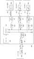
도 3은 다양한 실시 예에 따른 전자 장치의 세부 구성도이다.3 is a detailed configuration diagram of an electronic device according to various embodiments.
도 3에 따르면 전자 장치(500)는 DC 전원 포트(501), 제1 USB 입출력 포트(502), 제2 USB 입출력 포트(503), 제3 USB 출력 포트(504), 전원 제어부(505), 배터리(506), 장치 전원 제어부(507), 배터리 전원 변환부(508), 시스템 장치 전원 변환부(509), 제어부(510), 상태 표시부(511)를 포함할 수 있다. 이때, 전원 제어부(505)는 제1 전원 변환부(501a), 제2 전원 변환부(502a), 제3 전원 변환부(503a), 제4 전원 변환부(504a)를 포함할 수 있다.3, the
DC 전원 포트(501)는 AC 어댑터로부터 입력된 입력 전원을 전원 제어부(505)의 제1 전원 변환부(501a)로 전달할 수 있다.
제1 USB 입출력 포트(502)는 제1 외부 장치로부터 입력된 입력 전원을 전원 제어부(550)의 제2 전원 변환부(502a)로 전달하고, 제2 전원 변환부(502a)로부터 입력된 출력 전원을 제1 외부 장치로 전달할 수 있다.The first USB I /
제2 USB 입출력 포트(503)는 제2 외부 장치로부터 입력된 입력 전원을 전원 제어부(505)의 제3 전원 변환부(503a)로 전달하고, 제3 전원 변환부(503a)로부터 입력된 출력 전원을 제2 외부 장치로 전달할 수 있다.The second USB I /
USB 출력 포트(504)는 제4 전원 변환부(504a)로부터 입력된 출력 전원을 제3 외부 장치로 전달할 수 있다.The
전원 제어부(505)는 DC 전원 포트(501), 제1 USB 입출력 포트(502), 제2 USB 입출력 포트(503), USB 출력 포트(504)를 통해서 입력된 입력 전원들을 가산하여 출력할 수 있다. 특히, 전원 제어부(505)는 DC 전원 포트(501)를 통해서 입력된 입력 전원의 전압(Vad)을 변환하는 제1 전원 변환부(501a), 제1 USB 입출력 포트(502)를 통해서 입력된 입력 전원의 전압(Vbus1)을 변환하는 제2 전원 변환부(502a), 제2 USB 입출력 포트(503)를 통해서 입력된 입력 전원의 전압(Vbus2)을 변환하는 제3 전원 변환부(503a), 출력 전원의 전압을 전압(Vbus3)으로 변환하는 제4 전원 변환부(504a)를 포함할 수 있다. 또한 전원 제어부(505)는 스위치를 더 구비하여 전원 입력 시 가산된 입력 전원을 전달하거나 전원 출력을 위해 출력 전원을 각 전원 변환부(501a, 502a, 503a, 504a)로 전달할 수 있다.The
제1 전원 변환부(501a)는 입력 전원의 전압(Vad)을 변환시켜 제1 전원(Ii1)을 출력할 수 있다.The first
제2 전원 변환부(502a)는 입력 전원의 전압(Vbus1)을 변환시켜 제2 전원(Ii2)을 출력할 수 있다.The second power
제3 전원 변환부(503a)는 입력 전원의 전압(Vbus2)을 변환시켜 제3 전원(Ii3)을 출력할 수 있다.The third
제4 전원 변환부(504a)는 출력 전원(Io4)의 전압을 변환시켜 제4 전압(Vbus3)을 가지는 제4 전원을 출력할 수 있다.The fourth
배터리(506)는 결합된 입력 전원을 공급받거나 공급된 입력 전원을 출력할 수 있다.The
장치 전원 제어부(507)는 가산된 입력 전원을 출력하기 위해 제1 스위치(505-1)의 온오프를 제어하거나 출력 전원을 전원 변환부들로 전달하기 위해 제2 스위치(505-2)의 온오프를 제어할 수 있다. 또한 배터리로부터 출력된 전원을 시스템 장치 전원 변환부(509)로 전달하기 위해 제3 스위치(506-1)의 온오프를 제어할 수 있다.The device
배터리 전원 변환부(508)는 배터리(506)로 입력되는 입력 전원(I_chg)을 변환하여 배터리(506)로 전달할 수 있다.The battery
시스템 장치 전원 변환부(509)는 배터리(506)로부터 전달된 입력 전원을 전자 장치(500)의 각 구성요소로 전달할 수 있다.The system unit
제어부(510)는 DC 전원 포트(501), 제1 USB 입출력 포트(502), 제2 USB 입출력 포트(503)를 통해서 개별적으로 입력된 입력 전원을 가산하기 위한 입력 전원의 전압 변환, 충전 및 외부 장치로의 전원 출력, 시스템 성능 감지(Monitoring) 및 제어를 수행할 수 있다.The
구체적으로, 제어부(510)는 DC 전원 포트(501), 제1 USB 입출력 포트(502), 제2 USB 입출력 포트(503)를 통해서 입력된 입력 전원들의 전압을 각 전원 변환부를 통해서 변환하고, 각 전원 변환부로부터 출력된 입력 전원들을 가산하여 배터리(510), 제3 USB 출력 포트에 연결된 제3 외부 장치, 전자 장치(500)의 내부 장치들(예: CPU, GPU, LCD 등) 등과 같은 타겟 장치로 전달되도록 전원 제어부(505)를 제어할 수 있다.Specifically, the
구체적으로, 전원 제어부(505)는 전원 입력 및 전원 출력을 모니터링하기 위한 모니터링 신호(Vio_monitor)를 제어부(510)로 전달할 수 있다. 전원 제어부(505)는 DC 전원 포트(501), 제1 USB 입출력 포트(502), 제2 USB 입출력 포트(503)를 통해서 각 전원 변환부로 입력되는 입력 전원이 있는지 감지하거나 각 전원 변환부에서 제1 USB 입출력 포트(502), 제2 USB 입출력 포트(503), 제3 USB 출력 포트(504)로 출력되는 출력 전원이 있는지 감지하여 이에 대한 응답 신호를 제어부(510)로 전달할 수 있다.Specifically, the
제어부(510)는 전원 입력 및 출력 제어를 위한 입출력 제어 신호(Vio_control)를 전원 제어부(505)로 전달하여 DC 전원 포트(501), 제1 USB 입출력 포트(502), 제2 USB 입출력 포트(503)를 통해서 입력된 입력 전원의 전압을 변환하여 가산하거나 출력 신호의 전압을 변환하여 DC 전원 포트(501), 제1 USB 입출력 포트(502), 제2 USB 입출력 포트(503), 제3 USB 출력 포트(504)로 전달하도록 전원 제어부(505)를 제어할 수 있다.The
제어부(510)는 DC 전원 포트(501)를 통해서 입력된 제1 입력 전원, 제1 USB 입출력 포트(502)로부터 입력된 제2 입력 전원, 제2 USB 입출력 포트(503)를 통해서 입력된 제3 입력 전원을 감지되면 제1 입력 전원, 제2 입력 전원, 제3 입력 전원의 각 전압을 변환하고, 전압이 변환된 제1 입력 전원, 제2 입력 전원, 제3 입력 전원을 가산하도록 전원 제어부(505)를 제어할 수 있다. 이러한 입력 전원들의 전압에 대한 변환은 전자 장치(500)의 배터리에 대한 고속 충전 및 전체 충전이 필요한지 여부, 외부 장치로의 전원 공급이 필요한지 여부, 전자 장치(500)의 성능 향상을 위한 추가 전원이 필요한지 여부, 전자 장치(500)의 동작 수행을 위한 추가 전원이 필요한지 여부 등과 같은 변환 조건에 따라 결정될 수 있다.The
이에 대해서 구체적으로 살펴보면, 예를 들어, DC 전원 포트(501)를 통해서 입력된 제1 입력 전원의 전압이 20V이고, 제1 USB 입출력 포트(502)로부터 입력된 제2 입력 전원의 전압이 5V이며, 제2 USB 입출력 포트(503)를 통해서 입력된 제3 입력 전원의 전압이 12V인 경우 제어부(510)는 변환 조건에 따라 각 입력 전원들의 전압을 특정 전압으로 변환할지 여부를 판단할 수 있다. 여기서, USB 입출력 포트에서 제공하는 전원의 전압은 5V, 9V, 12V, 20V로 설명하지만 이러한 전압은 다양한 전압으로 설정될 수 있다.Specifically, for example, when the voltage of the first input power source input through the DC
만약 전자 장치(500)의 배터리(506)에 대한 고속 충전 또는 외부 장치로의 전원 공급이 필요하다고 판단되면 제어부(510)는 제1 입력 전원, 제2 입력 전원, 제3 입력 전원의 각 전압을 고속 충전 또는 최대 전원을 위한 최적의(Optimized) 전압(Vio)으로 변환하도록 전원 제어부(505)를 제어할 수 있다. 예를 들어, 배터리(506)에 대한 고속 충전이 필요한 경우 제어부(510)는 Vio를 배터리(510)의 전압(Vbatt)인 20V으로 결정하고, 제2 전원, 제3 전원의 전압을 20V로 승압시키고, 제1 전원, 제2 전원, 제3 전원을 가산하여 출력하도록 전원 제어부(505)를 제어할 수 있다.If it is determined that fast charging of the
만약 전자 장치(500)의 배터리(506)에 대한 고속 충전 또는 외부 장치로의 전원 공급 이외에 전자 장치(500)의 성능 향상 또는 동작을 위한 전원 공급이 필요하다고 판단되면 제어부(510)는 제1 입력 전원, 제2 입력 전원, 제3 입력 전원의 각 전압을 최고 성능을 위한 최적의 전압(Vio)으로 변환하도록 전원 제어부(505)를 제어할 수 있다.If it is determined that the
예를 들어, 성능 향상을 위해 필요한 추가 전원의 전압이 5V인 경우 제어부(510)는 Vio를 5V로 결정하고, 제1 전원의 전원을 5V로 강압시키고, 제3 전원의 전압을 5V로 강압시키며, 제1 전원, 제2 전원, 제3 전원을 가산하여 출력하도록 전원 제어부(505)를 제어할 수 있다.For example, when the voltage of the additional power source required for improving the performance is 5V, the
상기에서는 DC 전원 포트(501)를 통해서 입력된 전원을 포함하는 실시 예를 설명하였으나, DC 전원 포트(501)를 통한 전원 입력 없이 둘 이상의 USB 입출력 포트를 통해서 입력되는 전원의 전압을 최적의 전압으로 변환하여 가산한 후 출력할 수 있다.Although the embodiment has been described with reference to the embodiment that includes the power input through the
본 발명의 실시 예에서는 장치 전원 제어부(507)와 제어부(510)를 별도로 구성되는 것을 설명하였으나, 장치 전원 제어부(507)와 제어부(510)가 하나로 구성되거나 제어부(510) 내에 장치 전원 제어부(507)가 포함되어 구성될 수도 있다.The device
또한 본 발명의 실시 예에서 각 USB 포트들은 타입-C USB 규격(예: USB Type-C Spec 1.0 및 Spec. PD 2.0)에 따라 구현될 수 있다.Also, in the embodiment of the present invention, each USB port can be implemented according to the Type-C USB specification (e.g., USB Type-C Spec 1.0 and Spec. PD 2.0).
본 발명의 실시 예에 따르면 전자 장치에 장착된 각 개별 USB 포트들의 전원 입력 감지, 입력 전원의 전압/전류 레벨 감지 및 입력 전원(Vbus) 제어 등과 같은 동작은 CC 신호선(Configuration Channel)을 통해 이루어질 수 있다. 또한 이러한 동작은 기본적으로 USB PD 규격과 호환될 수 있고, AC/DC 어뎁터와 같이 USB PD 규격을 따르지 않은 레거시(Legacy) 전원 입력은 별도의 신호선을 통해서 가능할 수 있다.According to the embodiment of the present invention, operations such as power input detection, voltage / current level detection of input power and input power (Vbus) control of each individual USB ports mounted on the electronic device can be performed through a CC signal line have. In addition, such operation can be basically compatible with the USB PD standard, and a legacy power input that does not conform to the USB PD standard like the AC / DC adapter can be provided through a separate signal line.
상태 표시부(511)는 전자 장치(500)의 배터리 상태, 전자 포트 및 USB 포트의 상태를 표시할 수 있다. 구체적으로, 상태 표시부(511)는 각 포트들의 입력 및 출력 상태, 전자 장치(500)의 전체 전원 상태(예: 외부 전원 입력이 없음, 전제 충전, 충전 중, 성능 향상을 위한 추가 전원 입력 중 등) 등과 같은 전자 장치(500)의 전원 및 성능 상태를 표시할 수 있다. 이러한 상태 표시부(511)는 소프트웨어, LED 등을 이용한 하드웨어, 소프트웨어와 하드웨어를 결합하여 구현 가능하다.The
도 4는 다양한 실시 예에 따라 DC 전원 포트에 대응하는 제1 전원 변환부의 세부 구성도이다.4 is a detailed configuration diagram of a first power conversion unit corresponding to a DC power port according to various embodiments.
도 4에 따라 전원이 입력되면 DC 전원 포트(501)는 입력된 전원을 제1 전원 제어부(501a)로 전달한다. 이때, DC 전원 포트(501)는 제어부(510)와 연결된 신호선을 통해서 감지 신호를 제어부(510)로 전달할 수 있다.4, the
감지 신호를 수신한 제어부(510)는 입력된 전원의 전압을 변환하여 출력하도록 제1 전원 변환부(501a)를 제어할 수 있다. 이때, 제어부(510)는 입력된 전원이 제1 전원 변환부(501a)의 입력 전원 변환부(501-1)로 전달되도록 스위치(501-2)의 온오프를 제어할 수 있다.The
제1 전원 변환부(501a)에 구비된 입력 전원 변환부(501-1)는 입력된 전원의 전압을 전자 장치(500)에서 사용할 수 있는 전압으로 변환하여 출력할 수 있다.The input power conversion unit 501-1 provided in the first
본 발명의 실시 예에서는 AC 어댑터로부터 전원 입력이 있으면 AC 어댑터로부터 입력된 전압을 디폴트 입력 전압으로 설정하고, 다른 타입-C 형태의 USB 포트로부터 입력된 전원의 전압을 AC 전압으로 변환되도록 제1 전원 변환부(501a)를 구성할 수도 있다.In the embodiment of the present invention, when there is a power input from the AC adapter, the voltage input from the AC adapter is set as the default input voltage, and the voltage of the power source inputted from the USB port of the other type- The
도 6은 다양한 실시 예에 따라 제1 USB 입출력 포트에 대응하는 제2 전원 변환부의 세부 구성도이다.6 is a detailed configuration diagram of a second power conversion unit corresponding to a first USB input / output port according to various embodiments.
도 6에 따라 전원이 입력되면 제1 USB 입출력 포트(502)는 입력된 전원을 제2 전원 변환부(501a)로 전달한다. 이때, DC 전원 포트(501)는 제어부(510)와 연결된 CC 신호선을 통해서 감지 신호를 제2 전원 변환부(502a)의 신호 감지부(502-3)로 전달하고, 신호 감지부(502-3)는 감지 신호를 제어부(510)로 전달할 수 있다.6, the first USB input /
감지 신호를 수신한 제어부(510)는 입력된 전원의 전압을 변환하여 출력하도록 제2 전원 변환부(502a)를 제어할 수 있다. 이때, 제어부(510)는 입력된 전원이 제2 전원 변환부(502a)의 입력 전원 변환부(502-1)로 전달되도록 스위치(502-4)의 온오프를 제어할 수 있다.The
제2 전원 제어부(502a)에 구비된 입력 전원 변환부(502-1)는 입력된 전원의 전압을 전자 장치(500)에서 사용할 수 있는 전압으로 변환하여 출력할 수 있다. 특히, 입력 전원 변환부(502-1)는 입력된 전원의 전압을 변환 조건에 따라 결정된 최적의 전원(Vio)으로 변환할 수 있다.The input power conversion unit 502-1 included in the second
전원 출력에 대한 감지 신호가 수신되면 제어부(510)는 출력 전원의 전압을 변환하여 출력하도록 제2 전원 제어부(502a)를 제어할 수 있다. 이때, 제어부(510)는 출력 전원이 제1 USB 입출력 포트(502)로 전달되도록 스위치(502-5)의 온오프를 제어할 수 있다.When the detection signal for the power output is received, the
출력 전원이 입력되면 제2 전원 제어부(502a)는 제2 외부 장치로 출력하기 위해 출력 전원 변환부(502-2)를 통해서 출력 전원의 전압을 변환하여 제1 USB 입출력 포트(502)로 전달할 수 있다. 특히, 제2 전원 제어부(502a)의 출력 전원 변환부(502-2)는 출력 전원의 전압을 제1 USB 입출력 포트(502)와 연결된 제2 외부 장치에서 사용 가능한 전압으로 변환할 수 있다.When the output power is input, the second
본 발명의 실시 예에서 세부 출력 전압 레벨 및 전류는 USB PD 규격을 기반으로 결정될 수 있다.In an embodiment of the present invention, the detailed output voltage level and current may be determined based on the USB PD standard.
도 7은 다양한 실시 예에 따라 USB 출력 포트에 대응하는 전원 제어부의 세부 구성도이다.7 is a detailed configuration diagram of a power control unit corresponding to a USB output port according to various embodiments.
도 7에 따라 전원 출력에 대한 감지 신호가 수신되면 제어부(510)는 출력 전원의 전압을 변환하여 출력하도록 제4 전원 제어부(504a)를 제어할 수 있다. 이때, 제어부(510)는 출력 전원이 제3 USB 출력 포트(504a)로 전달되도록 스위치(504-3)의 온오프를 제어할 수 있다.7, when the sensing signal for the power output is received, the
출력 전원이 입력되면 제4 전원 제어부(502a)는 제3 외부 장치로 출력하기 위해 출력 전원 변환부(504-1)를 통해서 출력 전원의 전압을 변환하여 제3 USB 출력 포트(504)로 전달할 수 있다. 특히, 제4 전원 제어부(504a)의 출력 전원 변환부(504-1)는 출력 전원의 전압을 제3 USB 출력 포트(504)와 연결된 제3 외부 장치에서 사용 가능한 전압으로 변환할 수 있다.When the output power is input, the fourth
상기와 같이 설명된 각 전원 변환부들은 도 9와 같이 전자 장치 내에 구현되어 상기의 도 5에서 설명한 바와 같은 동작들을 수행할 수 있다.Each of the power conversion units described above may be implemented in the electronic device as shown in FIG. 9 to perform the operations as described with reference to FIG.
본 발명의 실시 예에서 입출력 포트들은 적용하고자 하는 시스템의 설계 비용 및 사양에 따라 선택적으로 결정될 수 있는데, 예를 들어, 하기의 표와 같이 AC/DC 전원 포트 및 USB 포트에 대한 구성을 나타낼 수 있다.In the embodiment of the present invention, the input / output ports can be selectively determined according to the design cost and specification of the system to be applied. For example, the configurations of the AC / DC power port and the USB port can be shown as the following table .
상기의 [표 1]은 하나의 전원 포트와 하나의 타입-C 포트를 구비하는 전자 장치의 예를 보여주는 것으로, 이러한 전자 장치는 초경박 및 초경량의 장치로서 얇은 클램쉘(Clamshell) 및 태블릿 형태의 제품을 포함할 수 있다.[Table 1] shows an example of an electronic device having one power port and one type-C port, and the electronic device is a thin-walled and light-weight device, such as a thin clamshell and a tablet- Products.
상기의 [표 2]는 하나의 전원 포트와 두 개의 타입-C 포트를 구비하는 전자 장치의 예를 보여주는 것으로, 제3 동적 구성의 예와 같이 AC/DC 전원 포트를 통해서 전원 입력이 없는 경우에도 2개의 포트를 통해서 외부 장지로부터 전원 공급을 받으면서 제1 포트를 통해서 다른 외부 장치로 전원을 공급할 수 있다. 추가적으로, 제4 동적 구성의 예에서는 제1 포트와 제2 포트를 통해서 동시에 입력된 두 개의 전원을 결합하여 대용량의 입력 전원을 장치의 성능 또는 사용성을 높이기 위해 효과적으로 사용할 수 있다.Table 2 shows an example of an electronic device having one power port and two type-C ports, and even when there is no power input through the AC / DC power port as in the third dynamic configuration example Power can be supplied to the other external device through the first port while receiving power from the external device through the two ports. Additionally, in the example of the fourth dynamic configuration, two power sources input at the same time through the first port and the second port may be combined to effectively use a large capacity input power to enhance the performance or usability of the device.
상기의 [표 3]은 하나의 전원 포트와 세 개의 타입-C 포트를 구비하는 전자 장치의 예를 보여주는 것으로, 향후 타입-C 형태의 포트에 대한 적용이 확대되면서 노트PC와 같은 IT 제품에서는 복수의 타입-C 포트를 적용하여 사용할 수 있다.Table 3 shows an example of an electronic device having one power supply port and three type-C ports. As the application to the type-C type port is expanded in the future, IT products such as a notebook PC Type-C port.
본 발명의 실시 예에서는 배럴 잭을 사용하는 전원 입력을 설명하였으나, 배럴 잭을 사용하는 대신에 USB PD를 지원하는 타입-A 및 타입-C 형태의 포트를 통해서 전원이 입력될 수 있다.Although the power supply input using the barrel jack has been described in the embodiment of the present invention, instead of using the barrel jack, the power can be input through the type-A and type-C type ports supporting the USB PD.
도 8은 다양한 실시 예에 따라 전원 입출력 시 제어부에서 전원 입출력을 처리하는 과정을 설명하기 위한 흐름도들이다.FIG. 8 is a flowchart illustrating a process of processing a power input / output in a controller during power input / output according to various embodiments.
도 8을 살펴보면 600동작에서 제어부(510)는 전원 포트 또는 USB 포트에 외부 장치가 연결되었는지 판단하여 외부 장치와 연결되어 있으면 601동작을 수행하고, 외부 장치와 연결되어 있지 않으면 605동작을 수행할 수 있다. 구체적으로, 제어부(510)는 AC/DC 어댑터가 전원 포트에 연결되거나 타입-C 형태의 USB 포트에 외부 장치가 장착되는 이벤트가 감지되는지 판단하여 이벤트가 감지되면 601동작 이하의 동작들을 수행할 수 있다.Referring to FIG. 8, in
601동작에서 제어부(510)는 전원 출력이 필요한지 판단하여 전원 출력이 필요하면 602단계로 진행하여 전원을 출력하고, 전원 출력이 필요하지 않으면 603동작을 진행한다. 구체적으로, 제어부(510)는 연결된 외부 장치로 전원 공급이 필요한 경우 출력 전원을 외부 장치와 연결된 USB 포트로 전달하여 외부 장치로 전원을 공급할 수 있다.In
603동작에서 제어부(510)는 전원 포트 또는 USB 포트를 통해서 전원이 입력되는지 판단하여 전원이 입력되면 605동작을 진행하고, 전원이 입력되지 않으면 604동작에서 외부 장치와의 데이터 통신을 수행한 후 600동작으로 진행하여 600~612동작을 수행할 수 있다. 이때, USB 포트에 연결되는 외부 장치가 USB PD를 지원하지 않은 경우 전원 입력 처리를 수행하지 않고, 데이터 송수신 및 USB 규격에 규정된 전원을 출력할 수 있다. 또한 USB 포트에 연결되는 외부 장치가 USB PD를 지원하는 경우 USB PD 프로토콜을 이용하여 605동작 이하의 동작들을 수행할 수 있다.In
605동작에서 제어부(510)는 배터리(510)의 전체가 충전되었는지 판단하여 배터리(510)의 전체가 충전되면 606동작으로 진행하고, 배터리(510)의 전체가 충전되지 않으면 609동작을 수행할 수 있다.In
606동작에서 제어부(510)는 장치 동작을 위한 추가 전원이 필요한지 판단하여 추가 전원이 필요하면 608동작으로 진행하고, 추가 전원이 필요하지 않으면 607동작으로 진행하여 상태 표시부(511)를 통해서 배터리(607)가 전체 충전 상태임을 알릴 수 있다.In
608동작에서 제어부(510)는 전자 장치(500)의 CPU 및 GPU 성능의 증가 및 LCD 밝기 증가 등과 같은 추가 동작을 수행하기 위한 추가 전원이 필요하면 전자 장치(500)의 최고 성능을 위한 입력 전원의 전압을 결정한 후 614동작으로 진행할 수 있다.In
예를 들어, CPU에서 사용 가능한 전원의 전압이 12V인 경우 제어부(510)는 최적의 전압(Vio)을 12V로 결정할 수 있다.For example, when the voltage of the power source available to the CPU is 12V, the
609동작에서 제어부(510)는 전자 장치(500)의 배터리(510)에 대한 고속 충전이 필요한지 판단하여 고속 충전이 필요하면 제어부(510)는 610동작으로 진행하여 고속 충전을 위한 입력 전원의 전압을 결정하고, 고속 충전이 필요하지 않으면 611동작으로 진행할 수 있다. 구체적으로, 제어부(510)는 입력 전원의 전압을 배터리(511)에서 사용 가능한 전원의 전압으로 결정할 수 있다. 만약 배터리(511)에서 사용 가능한 전원의 전압이 20V인 경우 제어부(510)는 최적의 전압(Vio)을 20V로 결정할 수 있다.In operation 609, the
611동작에서 제어부(510)는 성능 향상을 위한 추가 전원이 필요한지 판단하여 추가 전원이 필요하면 612동작으로 진행하여 최대 전원을 위한 입력 전원의 전압을 결정하고, 추가 전원이 필요하지 않으면 614동작으로 진행할 수 있다. 예를 들어, CPU 성능을 향상시키기 위해 필요한 전원의 전압이 5V인 경우 제어부(510)는 최적의 전압(Vio)을 5V로 결정할 수 있다.In
613동작에서 제어부(510)는 최고 효율을 위한 입력 전원의 전압을 결정할 수 있다. 예를 들어, 최고 효율을 위해 필요한 전원의 전압이 9V인 경우 제어부(510)는 최적의 전압(Vio)을 9V로 결정할 수 있다.608, 610, 612, 613 동작에서 614동작으로 진행한 제어부(510)는 입력 전원의 전압을 결정된 전압으로 변경하도록 각 전원 변환부를 제어할 수 있다. 예를 들어, 제1 USB 입출력 포트(502)를 통해서 입력되는 제2 전원(Vbus2)의 전압이 12V이고, 제2 USB 입출력 포트(602)를 통해서 입력되는 제3 전원(Vbus3)의 5V이며, 결정된 최적의 전압(Vio)이 9V인 경우 제어부(510)는 12V를 9V로 강압시키고, 5V를 9V로 승압시키도록 각 전원 변환부를 제어할 수 있다.In operation 613, the
고속 충전을 위해 결정된 최적의 전압(Vio)이 20V인 경우 제어부(510)는 12V를 20V로 승압시키고, 5V를 20V로 승압시키도록 각 전원 변환부를 제어할 수 있다.When the optimal voltage Vio determined for fast charging is 20V, the
성능 향상을 위해 결정된 최적의 전압(Vio)이 최적의 전압(Vio)이 5V인 경우 제어부(510)는 12V를 5V로 강압시키도록 각 전원 변환부를 제어할 수 있다.The
615동작에서 제어부(510)는 전압이 변환된 입력 전원들을 가산하여 출력하도록 전원 제어부(505)를 제어할 수 있다. 예를 들어, 제어부(510)는 제1 USB 입출력 포트(502)를 통해서 입력된 제2 전원(Vbus2)과 제2 USB 입출력 포트(602)를 통해서 입력된 제3 전원(Vbus3)을 가산하여 배터리(506) 또는 전자 장치의 내부 장치로 전달하거나 외부 장치로 전달되도록 전원 제어부(505)를 제어할 수 있다.In
본 발명의 실시 예에서는 저용량의 AC/DC 어댑터를 제공받더라도 전자 장치(500)의 추가 전원이 필요할 시 복수의 타입-C 형태의 USB 포트를 통해서 전원을 공급받기 때문에 전자 장치(500)의 휴대성(Mobility) 및 사용성을 높일 수 있다.In the embodiment of the present invention, even when a low capacity AC / DC adapter is provided, power is supplied through a plurality of type-C type USB ports when an additional power source of the
또한 본 발명의 실시 예에서는 전자 장치(500)에 내장된 배터리(506)에 대한 급속 충전이 필요한 경우 USB 포트를 통해 추가적으로 전원을 공급받을 수 있기 때문에 전자 장치(500)의 내부 성능 또는 기능을 제한하지 않은 상태에서 충전 속도를 향상시킬 수 있다.Further, in the embodiment of the present invention, when the
도 9는 다양한 실시 예에 따라 전자 장치가 동작하지 않은 상태에서 전원 입출력 시 제어부에서 전원 입출력을 처리하는 과정을 설명하기 위한 흐름도이다.FIG. 9 is a flowchart illustrating a process of processing power input / output by the control unit during power input / output in a state where the electronic device is not operated according to various embodiments.
도 9를 살펴보면 700동작에서 제어부(510)는 전원 포트 또는 USB 포트에 외부 장치가 연결되었는지 판단하여 외부 장치와 연결되어 있으면 701동작을 수행하고, 외부 장치와 연결되어 있지 않으면 704동작을 수행할 수 있다. 구체적으로, 제어부(510)는 AC/DC 어댑터가 전원 포트에 연결되거나 타입-C 형태의 USB 포트에 외부 장치가 장착되는 이벤트가 감지되는지 판단하여 이벤트가 감지되면 701동작 이하의 동작들을 수행할 수 있다.Referring to FIG. 9, in
701동작에서 제어부(510)는 전원 출력이 필요한지 판단하여 전원 출력이 필요하면 702단계로 진행하여 전원을 출력하고, 전원 출력이 필요하지 않으면 703동작을 진행한다. 구체적으로, 제어부(510)는 연결된 외부 장치로 전원 공급이 필요한 경우 출력 전원을 외부 장치와 연결된 USB 포트로 전달하여 외부 장치로 전원을 공급할 수 있다.In
703동작에서 제어부(510)는 전원 포트 또는 USB 포트를 통해서 전원이 입력되는지 판단하여 전원이 입력되면 704동작을 진행하고, 전원이 입력되지 않으면 700동작으로 진행하여 외부 장치가 연결되었는지 판단하여 701~710동작을 수행할 수 있다.In
704동작에서 제어부(510)는 배터리(510)의 전체가 충전되었는지 판단하여 배터리(510)의 전체가 충전되면 705동작으로 진행하여 상태 표시부(511)를 통해서 배터리(607)가 전체 충전 상태임을 알리고, 배터리(510)의 전체가 충전되지 않으면 706동작을 수행할 수 있다.In
706동작에서 제어부(510)는 전자 장치(500)의 배터리(510)에 대한 고속 충전이 필요한지 판단하여 고속 충전이 필요하면 제어부(510)는 707동작으로 진행하여 고속 충전을 위한 입력 전원의 전압을 결정하고, 고속 충전이 필요하지 않으면 708동작으로 진행할 수 있다. 구체적으로, 제어부(510)는 입력 전원의 전압을 배터리(511)에서 사용 가능한 전원의 전압으로 결정할 수 있다. 만약 배터리(511)에서 사용 가능한 전원의 전압이 20V인 경우 제어부(510)는 최적의 전압(Vio)을 20V로 결정할 수 있다.In
708동작에서 제어부(510)는 최고 효율을 위한 입력 전원의 전압을 결정할 수 있다. 예를 들어, 최고 효율을 위해 필요한 전원의 전압이 12V인 경우 제어부(510)는 최적의 전압(Vio)을 12V로 결정할 수 있다.In
707, 708 동작에서 709동작으로 진행한 제어부(510)는 입력 전원의 전압을 결정된 전압으로 변경하도록 각 전원 변환부를 제어할 수 있다. 예를 들어, 제1 USB 입출력 포트(502)를 통해서 입력되는 제2 전원(Vbus2)의 전압이 12V이고, 제2 USB 입출력 포트(602)를 통해서 입력되는 제3 전원(Vbus3)의 5V이며, 고속 충전을 위해 결정된 최적의 전압(Vio)이 20V인 경우 제어부(510)는 12V를 20V로 승압시키고, 5V를 20V로 승압시키도록 각 전원 변환부를 제어할 수 있다. 또한 최고 효율을 위해 결정된 최적의 전압(Vio)이 최적의 전압(Vio)이 12V인 경우 제어부(510)는 5V를 12V로 승압시키도록 전원 변환부를 제어할 수 있다.The
710동작에서 제어부(510)는 전압이 변환된 입력 전원들을 가산하여 출력하도록 전원 제어부(505)를 제어할 수 있다.In
이와 같이 본 발명의 다양한 실시 예에서는 USB 전원 입출력 포트 및 전원 포트를 통해서 입력된 전원을 가산하여 전자 장치에서 필요로 하는 대용량의 전원을 공급할 수 있다.As described above, in various embodiments of the present invention, the power input through the USB power input / output port and the power port can be added to supply a large capacity power required by the electronic device.
또한 본 발명의 다양한 실시 예에서는 다수의 소형 랩탑, 태블릿 PC 또는 스마트폰과 같은 외부 장치로부터 입력되는 전원을 결합하여 전자 장치의 최대 성능을 위한 고용량의 전원을 공급하거나 전자 장치의 성능 또는 기능을 제한하지 않은 상태에서 전원을 공급받아 전자 장치에 구비된 배터리 충전 속도를 개선시킬 수 있다.Also, in various embodiments of the present invention, power supplied from an external device such as a number of small laptops, tablet PCs, or smart phones may be combined to provide a high capacity power supply for maximum performance of the electronic device, The battery charging speed of the electronic device can be improved.
뿐만 아니라 본 발명의 다양한 실시 예에서는 대용량의 AC/DC 어댑터를 이용하지 않더라도 타입-C 형태의 USB 전원 입출력 포트를 이용하여 언제 어디서나 쉽게 필요한 대용량의 전원을 확보할 수 있기 때문에 전자 장치의 휴대성을 향상시킬 수 있고, 설계 비용을 절감할 수 있다.In addition, in various embodiments of the present invention, even if a large-capacity AC / DC adapter is not used, a large-capacity power source can be easily secured at any time by using a type-C type USB power input / output port. And the design cost can be reduced.
110: 버스
120: 프로세서
130: 메모리
140: 입출력 인터페이스
150: 디스플레이
160: 통신 인터페이스
170: 제어 모듈110: bus
120: Processor
130: memory
140: Input / output interface
150: Display
160: Communication interface
170: Control module
Claims (15)
Translated fromKorean상기 제1 포트에 연결되는 제1 외부 장치로부터 공급되는 제1 전원을 변환하는 제1 전원 변환부 및 상기 제2 포트에 연결되는 제2 외부 장치로부터 공급되는 제2 전원을 변환하는 제2 전원 변환부를 포함하는 전원 제어부; 및
상기 제1 전원과 상기 제2 전원을 가산하여 타겟 장치에 전원이 공급되도록 상기 전원 제어부를 제어하는 제어부를 포함하는 동적 전원 제어를 위한 전자 장치.A plurality of ports including at least a first port and a second port capable of power input;
A first power conversion unit for converting a first power supplied from a first external device connected to the first port and a second power conversion unit for converting a second power supplied from a second external device connected to the second port, A power control unit including a power supply unit; And
And a control unit for controlling the power source control unit to add power to the target device by adding the first power source and the second power source.
상기 제1 전원의 전압과 상기 제2 전원의 전압 중 적어도 하나의 전압에 대한 변환이 필요한지 판단하고, 상기 변환이 필요한 경우 상기 적어도 하나의 전압을 변환하도록 상기 전원 제어부를 제어하는 동적 전원 제어를 위한 전자 장치.The apparatus of claim 1,
For controlling at least one voltage of the first power source and a voltage of the second power source and for controlling the power source control unit to convert the at least one voltage when the conversion is necessary, Electronic device.
상기 타겟 장치가 전원을 공급받는 배터리인 경우 상기 배터리의 충전이 필요한지 여부를 판단하여 상기 배터리의 충전이 필요하면 상기 제1 전원의 전압과 상기 제2 전원의 전압 중 적어도 하나의 전압을 상기 배터리의 전압으로 변환하도록 상기 전원 제어부를 제어하는 동적 전원 제어를 위한 전자 장치.3. The apparatus of claim 2,
If it is determined that the battery needs to be charged when the target device is a battery to be supplied with power, if it is necessary to charge the battery, at least one of a voltage of the first power source and a voltage of the second power source, Voltage to the power supply control unit.
상기 타겟 장치가 제3 외부 장치인 경우 상기 제3 외부 장치로의 전원 공급이 필요한지 여부를 판단하여 상기 제3 외부 장치로의 전원 공급이 필요하면 상기 제1 전원의 전압과 상기 제2 전원의 전압 중 적어도 하나의 전압을 상기 제3 외부 장치의 전압으로 변환하도록 상기 전원 제어부를 제어하는 동적 전원 제어를 위한 전자 장치.3. The apparatus of claim 2,
If the target device is a third external device, it is determined whether or not power supply to the third external device is necessary, and if it is necessary to supply power to the third external device, the voltage of the first power source and the voltage The voltage of at least one of the first external device and the second external device is converted into the voltage of the third external device.
상기 타겟 장치가 상기 전자 장치의 내부 장치인 경우 상기 내부 장치로의 추가 전원 공급이 필요한지 여부를 판단하여 상기 내부 장치로의 추가 전원 공급이 필요하면 상기 제1 전원의 전압과 상기 제2 전원의 전압 중 적어도 하나의 전압을 상기 내부 장치의 전압으로 변환하도록 상기 전원 제어부를 제어하는 동적 전원 제어를 위한 전자 장치.3. The apparatus of claim 2,
If the target device is an internal device of the electronic device, it is determined whether or not additional power supply to the internal device is necessary, and if additional power supply to the internal device is required, the voltage of the first power source and the voltage To convert the at least one voltage of the internal device into a voltage of the internal device.
전원 공급 장치, USB 입출력 포트, USB 입력 포트, USB 출력 포트 중 적어도 두 개를 포함하는 동적 전원 제어를 위한 전자 장치.2. The apparatus of claim 1, wherein the at least first and second ports comprise:
A power supply, a USB input / output port, a USB input port, and a USB output port.
USB 타입-C 형태로 구현되는 동적 전원 제어를 위한 전자 장치.7. The apparatus of claim 6, wherein the USB input /
An electronic device for dynamic power control implemented in USB type-C form.
전원 입력이 가능한 제2 포트에 연결되는 제2 외부 장치로부터 제2 전원을 공급받는 동작;
상기 제1 전원 및 상기 제2 전원을 변환하는 동작; 및
상기 제1 전원과 상기 제2 전원을 가산하여 타겟 장치에 전원을 공급하는 동작;을 포함하는 동적 전원 제어를 위한 방법.Receiving a first power from a first external device connected to a first port capable of power input;
Receiving a second power from a second external device connected to a second port capable of power input;
Converting the first power source and the second power source; And
And adding power to the target device by adding the first power source and the second power source.
상기 제1 전원의 전압과 상기 제2 전원의 전압 중 적어도 하나의 전압에 대한 변환이 필요한지 판단하는 동작; 및
상기 변환이 필요한 경우 상기 적어도 하나의 전압을 변환하는 동작;을 포함하는 동적 전원 제어를 위한 방법.9. The method of claim 8, wherein the operation of converting the first power source and the second power source comprises:
Determining whether conversion of at least one of a voltage of the first power source and a voltage of the second power source is necessary; And
And converting the at least one voltage if the conversion is required.
상기 타겟 장치가 전원을 공급받는 배터리인 경우 상기 배터리의 충전이 필요한지 여부를 판단하는 동작; 및
상기 배터리의 충전이 필요하면 상기 제1 전원의 전압과 상기 제2 전원의 전압 중 적어도 하나의 전압을 상기 배터리의 전압으로 변환하는 동작;을 포함하는 동적 전원 제어를 위한 방법.10. The method of claim 9, wherein determining whether a conversion to the at least one voltage is required comprises:
Determining whether charging of the battery is necessary if the target device is a battery supplied with power; And
And converting at least one of a voltage of the first power source and a voltage of the second power source to a voltage of the battery when charging of the battery is required.
상기 타겟 장치가 제3 외부 장치인 경우 상기 제3 외부 장치로의 전원 공급이 필요한지 여부를 판단하는 동작; 및
상기 제3 외부 장치로의 전원 공급이 필요하면 상기 제1 전원의 전압과 상기 제2 전원의 전압 중 적어도 하나의 전압을 상기 제3 외부 장치의 전압으로 변환하는 동작;을 포함하는 동적 전원 제어를 위한 방법.10. The method of claim 9, wherein determining whether a conversion to the at least one voltage is required comprises:
Determining whether power supply to the third external device is necessary if the target device is a third external device; And
And converting the voltage of at least one of the voltage of the first power source and the voltage of the second power source into the voltage of the third external device when power supply to the third external device is required, Way.
상기 타겟 장치가 상기 전자 장치의 내부 장치인 경우 상기 내부 장치로의 추가 전원 공급이 필요한지 여부를 판단하는 동작; 및
상기 내부 장치로의 추가 전원 공급이 필요하면 상기 제1 전원의 전압과 상기 제2 전원의 전압 중 적어도 하나의 전압을 상기 내부 장치의 전압으로 변환하는 동작;을 포함하는 동적 전원 제어를 위한 방법.10. The method of claim 9, wherein determining whether a conversion to the at least one voltage is required comprises:
Determining whether additional power to the internal device is required if the target device is an internal device of the electronic device; And
And converting at least one of a voltage of the first power source and a voltage of the second power source to a voltage of the internal device when an additional power supply to the internal device is required.
전원 공급 장치, USB 입출력 포트, USB 입력 포트, USB 출력 포트 중 적어도 두 개를 포함하는 동적 전원 제어를 위한 방법.9. The apparatus of claim 8, wherein the first port and the second port comprise:
A method for dynamic power control comprising at least two of a power supply, a USB I / O port, a USB input port, and a USB output port.
USB 타입-C 형태로 구현되는 동적 전원 제어를 위한 방법.14. The system of claim 13, wherein the USB input /
A method for dynamic power control implemented in USB type-C form.
전원 입력이 가능한 제1 포트에 연결되는 제1 외부 장치로부터 제1 전원을 공급받는 동작;
전원 입력이 가능한 제2 포트에 연결되는 제2 외부 장치로부터 제2 전원을 공급받는 동작;
상기 제1 전원 및 상기 제2 전원을 변환하는 동작; 및
상기 제1 전원과 상기 제2 전원을 가산하여 타겟 장치에 전원을 공급하는 동작;을 실행시키기 위한 프로그램을 기록한 컴퓨터 판독 가능한 기록 매체.A recording medium storing instructions readable by a computer,
Receiving a first power from a first external device connected to a first port capable of power input;
Receiving a second power from a second external device connected to a second port capable of power input;
Converting the first power source and the second power source; And
And supplying power to the target device by adding the first power source and the second power source.
Priority Applications (3)
| Application Number | Priority Date | Filing Date | Title |
|---|---|---|---|
| KR1020150076705AKR20160140275A (en) | 2015-05-29 | 2015-05-29 | ELECTRONIC DEVICE AND METHOD FOR DYNAMIC POWER CONTROL |
| US15/158,953US20160352101A1 (en) | 2015-05-29 | 2016-05-19 | Electronic device and method for controlling dynamic power |
| EP16170568.6AEP3098922A1 (en) | 2015-05-29 | 2016-05-20 | Electronic device and method for controlling dynamic power |
Applications Claiming Priority (1)
| Application Number | Priority Date | Filing Date | Title |
|---|---|---|---|
| KR1020150076705AKR20160140275A (en) | 2015-05-29 | 2015-05-29 | ELECTRONIC DEVICE AND METHOD FOR DYNAMIC POWER CONTROL |
Publications (1)
| Publication Number | Publication Date |
|---|---|
| KR20160140275Atrue KR20160140275A (en) | 2016-12-07 |
Family
ID=56684424
Family Applications (1)
| Application Number | Title | Priority Date | Filing Date |
|---|---|---|---|
| KR1020150076705AWithdrawnKR20160140275A (en) | 2015-05-29 | 2015-05-29 | ELECTRONIC DEVICE AND METHOD FOR DYNAMIC POWER CONTROL |
Country Status (3)
| Country | Link |
|---|---|
| US (1) | US20160352101A1 (en) |
| EP (1) | EP3098922A1 (en) |
| KR (1) | KR20160140275A (en) |
Cited By (3)
| Publication number | Priority date | Publication date | Assignee | Title |
|---|---|---|---|---|
| KR20200099502A (en)* | 2019-02-14 | 2020-08-24 | 엘지전자 주식회사 | Power supply regulator and portable device therewith |
| KR102201172B1 (en)* | 2020-06-10 | 2021-01-11 | 한화시스템 주식회사 | Apparatus and method for distributing power of wearable device |
| US11190038B2 (en) | 2016-09-28 | 2021-11-30 | Samsung Electronics Co., Ltd | Electronic device for controlling power |
Families Citing this family (46)
| Publication number | Priority date | Publication date | Assignee | Title |
|---|---|---|---|---|
| US11025345B2 (en) | 2013-09-19 | 2021-06-01 | Radius Universal Llc | Hybrid cable providing data transmission through fiber optic cable and low voltage power over copper wire |
| US10855381B2 (en)* | 2013-09-19 | 2020-12-01 | Radius Universal Llc | Fiber optic communications and power network |
| WO2016030725A1 (en)* | 2014-08-29 | 2016-03-03 | Pismo Labs Technology Limited | Apparatus and method for a mobile router to receive power from a plurality of power supplies |
| US10411466B2 (en) | 2014-12-21 | 2019-09-10 | Pismo Lab Technology Limited | Apparatus and method for a mobile router to receive power from a plurality of power supplies |
| CN108351677B (en)* | 2015-11-13 | 2021-05-28 | 德州仪器公司 | Port controller with power contract negotiation capability |
| US11088549B2 (en)* | 2016-03-22 | 2021-08-10 | Intersil Americas LLC | Multiple chargers configuration in one system |
| US10594152B1 (en) | 2016-03-25 | 2020-03-17 | Intersil Americas LLC | Method and system for a battery charger |
| DE102017112598A1 (en)* | 2016-07-21 | 2018-01-25 | Intel Corporation | communication system |
| JP2018033244A (en)* | 2016-08-24 | 2018-03-01 | キヤノン株式会社 | Electronic device and control method thereof |
| TWI628548B (en)* | 2016-11-07 | 2018-07-01 | 全漢企業股份有限公司 | Universal serial bus hub |
| US10615632B2 (en)* | 2016-12-05 | 2020-04-07 | Eaton Intelligent Power Limited | Current sharing architecture for combination charger |
| KR102710750B1 (en)* | 2017-01-18 | 2024-09-27 | 삼성전자주식회사 | Method for charging control and electronic device supporting the same |
| US10454226B2 (en)* | 2017-04-07 | 2019-10-22 | Centurylink Intellectual Property Llc | Power distribution unit for transmitting data over a power line |
| JP2018206394A (en)* | 2017-06-08 | 2018-12-27 | 宸定科技股▲ふん▼有限公司SIM Power Technology Inc. | Hub |
| US11054878B2 (en)* | 2017-08-29 | 2021-07-06 | Texas Instruments Incorporated | Synchronous power state control scheme for multi-chip integrated power management solution in embedded systems |
| US11121560B2 (en)* | 2017-09-03 | 2021-09-14 | Google Llc | Hot-pluggable dual battery with pass through charging |
| CN107544934B (en)* | 2017-09-07 | 2020-07-07 | 龙迅半导体(合肥)股份有限公司 | Two-way signal conditioning chip and USBType-C cable of USBType-C cable |
| JP7071090B2 (en)* | 2017-10-31 | 2022-05-18 | キヤノン株式会社 | Power receiving device, power receiving device control method, and program |
| US10491023B2 (en)* | 2017-12-30 | 2019-11-26 | Texas Instruments Incorporated | Capacitor balanced driver circuit for dual input charger |
| GB201812211D0 (en) | 2018-07-26 | 2018-09-12 | Univ Manchester | Intelligent power module |
| WO2020076311A1 (en)* | 2018-10-10 | 2020-04-16 | Hewlett-Packard Development Company, L.P. | Additional power supplies |
| US11073889B2 (en)* | 2019-03-29 | 2021-07-27 | Ati Technologies Ulc | Apparatus and method for providing graphics processing unit (GPU) based power shifting for USB devices |
| US12278508B2 (en)* | 2019-06-17 | 2025-04-15 | Renesas Electronics America Inc. | Single inductor multiple output charger for multiple battery applications |
| US11108256B2 (en)* | 2019-08-01 | 2021-08-31 | Monolithic Power Systems, Inc. | Multi-port battery charge and discharge system |
| TW202107286A (en)* | 2019-08-13 | 2021-02-16 | 華碩電腦股份有限公司 | Usb expansion device |
| US11742332B2 (en)* | 2019-12-06 | 2023-08-29 | Wolfspeed, Inc. | Methods and systems for matching both dynamic and static parameters in dies, discretes, and/or modules, and methods and systems based on the same |
| TWM602743U (en)* | 2020-08-12 | 2020-10-11 | 華碩電腦股份有限公司 | Transmission device with exterior power supply |
| US12002720B2 (en) | 2020-11-23 | 2024-06-04 | Wolfspeed, Inc. | Methods and systems for component analysis, sorting, and sequencing based on component parameters and devices utilizing the methods and systems |
| US11847005B2 (en)* | 2021-02-11 | 2023-12-19 | Siliconch Systems Pvt Ltd | Compact USB-C based multiport power supply device and method of operation thereof |
| US20220350387A1 (en)* | 2021-04-30 | 2022-11-03 | Huddly As | USB/Thunderbolt to Ethernet Adapter with Dynamic Multiplex Power Supply |
| KR20240000349A (en)* | 2021-04-30 | 2024-01-02 | 허들리 인코포레이티드 | USB/Thunderbolt to Ethernet adapter with dynamic multiplex power supply |
| CN113489312B (en)* | 2021-06-29 | 2022-08-30 | 百富计算机技术(深圳)有限公司 | PD supply circuit and POS machine |
| CN115956227B (en)* | 2021-07-12 | 2025-04-29 | 高创(苏州)电子有限公司 | Electric signal transmission method, electric signal transmission control chip, and electric signal transmission system |
| EP4340166B1 (en)* | 2021-07-27 | 2025-10-15 | Samsung Electronics Co., Ltd. | Electronic apparatus for charging another electronic apparatus, and method for controlling electronic apparatus for charging other electronic apparatus |
| US11599149B2 (en)* | 2021-08-06 | 2023-03-07 | Dell Products, L.P. | Docking station supporting power inputs from a display |
| US20230100409A1 (en)* | 2021-09-30 | 2023-03-30 | Ati Technologies Ulc | Uniform distribution of peripheral power in asic platforms |
| US11870353B2 (en) | 2021-09-30 | 2024-01-09 | Microsoft Technology Licensing, Llc | Dynamic loading for a switching power supply |
| CN114039389B (en) | 2021-10-14 | 2024-12-24 | 昂宝电子(上海)有限公司 | Multi-port charging device and protocol handshake implementation architecture and method thereof |
| CN114552709A (en)* | 2022-02-21 | 2022-05-27 | 昂宝电子(上海)有限公司 | Multi-port USB charging system and control method thereof |
| CN115129646A (en)* | 2022-04-26 | 2022-09-30 | 成都芯源系统有限公司 | USB controller, USB power supply circuit and method thereof |
| CN116017663A (en)* | 2022-12-06 | 2023-04-25 | 北京小米移动软件有限公司 | Power adjustment method, device, electronic device and storage medium |
| EP4391453A1 (en)* | 2022-12-19 | 2024-06-26 | Schneider Electric Industries Sas | Improved networking apparatus for providing electrical power over wired data telecommunications networks |
| US20240427401A1 (en)* | 2023-06-20 | 2024-12-26 | Dell Products L.P. | External display device auxiliary power mechanism during power outage |
| US20250106067A1 (en)* | 2023-09-21 | 2025-03-27 | Phihong Technology Co., Ltd. | Unidirectional usb-c to power over ethernet converter for power with bidirectional data |
| US20250184176A1 (en)* | 2023-12-01 | 2025-06-05 | Phihong Technology Co., Ltd. | Poe to usb-c multiport switch |
| US20250199595A1 (en)* | 2023-12-15 | 2025-06-19 | Dish Network Technologies India Private Limited | Systems and methods for implementation power over ethernet |
Family Cites Families (7)
| Publication number | Priority date | Publication date | Assignee | Title |
|---|---|---|---|---|
| US7498694B2 (en)* | 2006-04-12 | 2009-03-03 | 02Micro International Ltd. | Power management system with multiple power sources |
| WO2008075140A1 (en)* | 2006-12-21 | 2008-06-26 | Nokia Corporation | Charging unit with two power source inputs |
| CN101364745B (en)* | 2007-08-08 | 2012-09-05 | 鹏智科技(深圳)有限公司 | Electronic apparatus capable of automatically choosing power supply source |
| JP4770954B2 (en)* | 2009-03-16 | 2011-09-14 | Tdk株式会社 | Multiple power supply integration device, multiple power supply integration system, and multiple power supply integration program |
| US20100244573A1 (en)* | 2009-03-31 | 2010-09-30 | Tanay Karnick | Hybrid power delivery system and method |
| EP3043442B1 (en)* | 2015-01-12 | 2024-12-04 | SIMPower Technology Inc. | Hub having complex power converters |
| TWI580162B (en)* | 2015-05-25 | 2017-04-21 | 立錡科技股份有限公司 | Power converter and control circuit and standby power saving method thereof |
- 2015
- 2015-05-29KRKR1020150076705Apatent/KR20160140275A/ennot_activeWithdrawn
- 2016
- 2016-05-19USUS15/158,953patent/US20160352101A1/ennot_activeAbandoned
- 2016-05-20EPEP16170568.6Apatent/EP3098922A1/ennot_activeWithdrawn
Cited By (3)
| Publication number | Priority date | Publication date | Assignee | Title |
|---|---|---|---|---|
| US11190038B2 (en) | 2016-09-28 | 2021-11-30 | Samsung Electronics Co., Ltd | Electronic device for controlling power |
| KR20200099502A (en)* | 2019-02-14 | 2020-08-24 | 엘지전자 주식회사 | Power supply regulator and portable device therewith |
| KR102201172B1 (en)* | 2020-06-10 | 2021-01-11 | 한화시스템 주식회사 | Apparatus and method for distributing power of wearable device |
Also Published As
| Publication number | Publication date |
|---|---|
| US20160352101A1 (en) | 2016-12-01 |
| EP3098922A1 (en) | 2016-11-30 |
Similar Documents
| Publication | Publication Date | Title |
|---|---|---|
| KR20160140275A (en) | ELECTRONIC DEVICE AND METHOD FOR DYNAMIC POWER CONTROL | |
| KR102341531B1 (en) | Apparatus and method for a charging of electronic device using battery | |
| US10283920B2 (en) | Interface device | |
| KR102184527B1 (en) | Electronic apparatus and method for wire and wireless charging in electronic apparatus | |
| KR102710750B1 (en) | Method for charging control and electronic device supporting the same | |
| KR102512619B1 (en) | Electronic apparatus and method for charging in electronic apparatus | |
| KR102337934B1 (en) | Electronic device and method for sharing electric power in wireless charging | |
| EP2911036B1 (en) | Method and apparatus for power sharing | |
| EP3767783B1 (en) | Battery charging method and electronic device | |
| KR102511514B1 (en) | Device and method for fast charging using various charge method | |
| US10168757B2 (en) | Method and apparatus for adaptively managing power | |
| US10256653B2 (en) | Electronic device and method for charging battery | |
| US10761498B2 (en) | Electronic device and method for operating the same | |
| CN107438935A (en) | Method and apparatus for wireless charging | |
| KR20170020147A (en) | Wireless charging method and apparatus thereof | |
| KR102579676B1 (en) | A method for providing power to a battery and an electronic device therefor | |
| KR20150141313A (en) | Method and apparatus for processing information of electronic devices | |
| KR20160057788A (en) | Wireless data input and output method and apparatus | |
| KR20180104987A (en) | Electronic apparatus and method for charging battery | |
| US20170170974A1 (en) | Method for controlling path of charging and data communication and electronic device implementing the same | |
| KR20150136345A (en) | Task group migration method and electronic device supporting the same | |
| KR102494466B1 (en) | Electronic apparatus and method for wire and wireless charging in electronic apparatus | |
| KR102499108B1 (en) | Electronic Device, Power Supply Apparatus for Electronic Device, and Power Supply Method Thereof | |
| KR20160111786A (en) | Method for power saving in electronic device and electronic device thereof | |
| AU2017205843B2 (en) | Electronic device and operating method thereof |
Legal Events
| Date | Code | Title | Description |
|---|---|---|---|
| PA0109 | Patent application | Patent event code:PA01091R01D Comment text:Patent Application Patent event date:20150529 | |
| PG1501 | Laying open of application | ||
| PC1203 | Withdrawal of no request for examination |