KR20160138232A - Quantitative three-dimensional imaging of surgical scenes - Google Patents
Quantitative three-dimensional imaging of surgical scenesDownload PDFInfo
- Publication number
- KR20160138232A KR20160138232AKR1020167029885AKR20167029885AKR20160138232AKR 20160138232 AKR20160138232 AKR 20160138232AKR 1020167029885 AKR1020167029885 AKR 1020167029885AKR 20167029885 AKR20167029885 AKR 20167029885AKR 20160138232 AKR20160138232 AKR 20160138232A
- Authority
- KR
- South Korea
- Prior art keywords
- image
- end portion
- image sensor
- dimensional
- target object
- Prior art date
- Legal status (The legal status is an assumption and is not a legal conclusion. Google has not performed a legal analysis and makes no representation as to the accuracy of the status listed.)
- Granted
Links
Images


Classifications
- H—ELECTRICITY
- H04—ELECTRIC COMMUNICATION TECHNIQUE
- H04N—PICTORIAL COMMUNICATION, e.g. TELEVISION
- H04N13/00—Stereoscopic video systems; Multi-view video systems; Details thereof
- H04N13/20—Image signal generators
- H04N13/204—Image signal generators using stereoscopic image cameras
- H04N13/25—Image signal generators using stereoscopic image cameras using two or more image sensors with different characteristics other than in their location or field of view, e.g. having different resolutions or colour pickup characteristics; using image signals from one sensor to control the characteristics of another sensor
- A—HUMAN NECESSITIES
- A61—MEDICAL OR VETERINARY SCIENCE; HYGIENE
- A61B—DIAGNOSIS; SURGERY; IDENTIFICATION
- A61B1/00—Instruments for performing medical examinations of the interior of cavities or tubes of the body by visual or photographical inspection, e.g. endoscopes; Illuminating arrangements therefor
- A61B1/04—Instruments for performing medical examinations of the interior of cavities or tubes of the body by visual or photographical inspection, e.g. endoscopes; Illuminating arrangements therefor combined with photographic or television appliances
- A61B1/05—Instruments for performing medical examinations of the interior of cavities or tubes of the body by visual or photographical inspection, e.g. endoscopes; Illuminating arrangements therefor combined with photographic or television appliances characterised by the image sensor, e.g. camera, being in the distal end portion
- A—HUMAN NECESSITIES
- A61—MEDICAL OR VETERINARY SCIENCE; HYGIENE
- A61B—DIAGNOSIS; SURGERY; IDENTIFICATION
- A61B1/00—Instruments for performing medical examinations of the interior of cavities or tubes of the body by visual or photographical inspection, e.g. endoscopes; Illuminating arrangements therefor
- A61B1/00002—Operational features of endoscopes
- A61B1/00004—Operational features of endoscopes characterised by electronic signal processing
- A61B1/00009—Operational features of endoscopes characterised by electronic signal processing of image signals during a use of endoscope
- A—HUMAN NECESSITIES
- A61—MEDICAL OR VETERINARY SCIENCE; HYGIENE
- A61B—DIAGNOSIS; SURGERY; IDENTIFICATION
- A61B1/00—Instruments for performing medical examinations of the interior of cavities or tubes of the body by visual or photographical inspection, e.g. endoscopes; Illuminating arrangements therefor
- A61B1/00163—Optical arrangements
- A61B1/00194—Optical arrangements adapted for three-dimensional imaging
- A—HUMAN NECESSITIES
- A61—MEDICAL OR VETERINARY SCIENCE; HYGIENE
- A61B—DIAGNOSIS; SURGERY; IDENTIFICATION
- A61B1/00—Instruments for performing medical examinations of the interior of cavities or tubes of the body by visual or photographical inspection, e.g. endoscopes; Illuminating arrangements therefor
- A61B1/04—Instruments for performing medical examinations of the interior of cavities or tubes of the body by visual or photographical inspection, e.g. endoscopes; Illuminating arrangements therefor combined with photographic or television appliances
- A61B1/05—Instruments for performing medical examinations of the interior of cavities or tubes of the body by visual or photographical inspection, e.g. endoscopes; Illuminating arrangements therefor combined with photographic or television appliances characterised by the image sensor, e.g. camera, being in the distal end portion
- A61B1/051—Details of CCD assembly
- A—HUMAN NECESSITIES
- A61—MEDICAL OR VETERINARY SCIENCE; HYGIENE
- A61B—DIAGNOSIS; SURGERY; IDENTIFICATION
- A61B1/00—Instruments for performing medical examinations of the interior of cavities or tubes of the body by visual or photographical inspection, e.g. endoscopes; Illuminating arrangements therefor
- A61B1/06—Instruments for performing medical examinations of the interior of cavities or tubes of the body by visual or photographical inspection, e.g. endoscopes; Illuminating arrangements therefor with illuminating arrangements
- A—HUMAN NECESSITIES
- A61—MEDICAL OR VETERINARY SCIENCE; HYGIENE
- A61B—DIAGNOSIS; SURGERY; IDENTIFICATION
- A61B34/00—Computer-aided surgery; Manipulators or robots specially adapted for use in surgery
- A61B34/30—Surgical robots
- G—PHYSICS
- G06—COMPUTING OR CALCULATING; COUNTING
- G06T—IMAGE DATA PROCESSING OR GENERATION, IN GENERAL
- G06T19/00—Manipulating 3D models or images for computer graphics
- G06T19/20—Editing of 3D images, e.g. changing shapes or colours, aligning objects or positioning parts
- G—PHYSICS
- G06—COMPUTING OR CALCULATING; COUNTING
- G06T—IMAGE DATA PROCESSING OR GENERATION, IN GENERAL
- G06T7/00—Image analysis
- G06T7/0002—Inspection of images, e.g. flaw detection
- G06T7/0012—Biomedical image inspection
- G06T7/0014—Biomedical image inspection using an image reference approach
- G—PHYSICS
- G06—COMPUTING OR CALCULATING; COUNTING
- G06T—IMAGE DATA PROCESSING OR GENERATION, IN GENERAL
- G06T7/00—Image analysis
- G06T7/70—Determining position or orientation of objects or cameras
- G06T7/73—Determining position or orientation of objects or cameras using feature-based methods
- G06T7/74—Determining position or orientation of objects or cameras using feature-based methods involving reference images or patches
- H—ELECTRICITY
- H04—ELECTRIC COMMUNICATION TECHNIQUE
- H04N—PICTORIAL COMMUNICATION, e.g. TELEVISION
- H04N13/00—Stereoscopic video systems; Multi-view video systems; Details thereof
- H04N13/20—Image signal generators
- H04N13/204—Image signal generators using stereoscopic image cameras
- H04N13/254—Image signal generators using stereoscopic image cameras in combination with electromagnetic radiation sources for illuminating objects
- H—ELECTRICITY
- H04—ELECTRIC COMMUNICATION TECHNIQUE
- H04N—PICTORIAL COMMUNICATION, e.g. TELEVISION
- H04N13/00—Stereoscopic video systems; Multi-view video systems; Details thereof
- H04N13/20—Image signal generators
- H04N13/275—Image signal generators from 3D object models, e.g. computer-generated stereoscopic image signals
- H—ELECTRICITY
- H04—ELECTRIC COMMUNICATION TECHNIQUE
- H04N—PICTORIAL COMMUNICATION, e.g. TELEVISION
- H04N13/00—Stereoscopic video systems; Multi-view video systems; Details thereof
- H04N13/30—Image reproducers
- H04N13/302—Image reproducers for viewing without the aid of special glasses, i.e. using autostereoscopic displays
- A—HUMAN NECESSITIES
- A61—MEDICAL OR VETERINARY SCIENCE; HYGIENE
- A61B—DIAGNOSIS; SURGERY; IDENTIFICATION
- A61B34/00—Computer-aided surgery; Manipulators or robots specially adapted for use in surgery
- A61B34/30—Surgical robots
- A61B34/37—Leader-follower robots
- G—PHYSICS
- G06—COMPUTING OR CALCULATING; COUNTING
- G06T—IMAGE DATA PROCESSING OR GENERATION, IN GENERAL
- G06T2200/00—Indexing scheme for image data processing or generation, in general
- G06T2200/04—Indexing scheme for image data processing or generation, in general involving 3D image data
- G—PHYSICS
- G06—COMPUTING OR CALCULATING; COUNTING
- G06T—IMAGE DATA PROCESSING OR GENERATION, IN GENERAL
- G06T2200/00—Indexing scheme for image data processing or generation, in general
- G06T2200/24—Indexing scheme for image data processing or generation, in general involving graphical user interfaces [GUIs]
- G—PHYSICS
- G06—COMPUTING OR CALCULATING; COUNTING
- G06T—IMAGE DATA PROCESSING OR GENERATION, IN GENERAL
- G06T2207/00—Indexing scheme for image analysis or image enhancement
- G06T2207/10—Image acquisition modality
- G06T2207/10068—Endoscopic image
- G—PHYSICS
- G06—COMPUTING OR CALCULATING; COUNTING
- G06T—IMAGE DATA PROCESSING OR GENERATION, IN GENERAL
- G06T2219/00—Indexing scheme for manipulating 3D models or images for computer graphics
- G06T2219/20—Indexing scheme for editing of 3D models
- G06T2219/2016—Rotation, translation, scaling
- H—ELECTRICITY
- H04—ELECTRIC COMMUNICATION TECHNIQUE
- H04N—PICTORIAL COMMUNICATION, e.g. TELEVISION
- H04N13/00—Stereoscopic video systems; Multi-view video systems; Details thereof
- H04N13/20—Image signal generators
- H04N13/204—Image signal generators using stereoscopic image cameras
- H04N13/207—Image signal generators using stereoscopic image cameras using a single 2D image sensor
- H—ELECTRICITY
- H04—ELECTRIC COMMUNICATION TECHNIQUE
- H04N—PICTORIAL COMMUNICATION, e.g. TELEVISION
- H04N2213/00—Details of stereoscopic systems
- H04N2213/001—Constructional or mechanical details
Landscapes
- Engineering & Computer Science (AREA)
- Health & Medical Sciences (AREA)
- Life Sciences & Earth Sciences (AREA)
- Surgery (AREA)
- Physics & Mathematics (AREA)
- Signal Processing (AREA)
- Medical Informatics (AREA)
- General Health & Medical Sciences (AREA)
- Nuclear Medicine, Radiotherapy & Molecular Imaging (AREA)
- Multimedia (AREA)
- Heart & Thoracic Surgery (AREA)
- Biomedical Technology (AREA)
- Molecular Biology (AREA)
- Animal Behavior & Ethology (AREA)
- Public Health (AREA)
- Veterinary Medicine (AREA)
- Radiology & Medical Imaging (AREA)
- Biophysics (AREA)
- Optics & Photonics (AREA)
- Pathology (AREA)
- General Physics & Mathematics (AREA)
- Theoretical Computer Science (AREA)
- Computer Vision & Pattern Recognition (AREA)
- Robotics (AREA)
- Electromagnetism (AREA)
- Computer Graphics (AREA)
- Architecture (AREA)
- Computer Hardware Design (AREA)
- General Engineering & Computer Science (AREA)
- Software Systems (AREA)
- Quality & Reliability (AREA)
- Endoscopes (AREA)
- Instruments For Viewing The Inside Of Hollow Bodies (AREA)
- Closed-Circuit Television Systems (AREA)
- Testing, Inspecting, Measuring Of Stereoscopic Televisions And Televisions (AREA)
Abstract
Translated fromKorean
Description
Translated fromKorean본 출원은, 전체 내용이 본 명세서에 참고로 포함되어 있는, 2014년 3월 28일자로 출원되고, 발명의 명칭이 "수술 장면의 정량적인 3차원 영상(QUANTITATIVE THREE-DIMENSIONAL IMAGING OF SURGICAL SCENES)"인 미국 가특허 출원 제61/971,749호에 대해 우선권의 이익을 주장한다.This application claims the benefit of U.S. Provisional Patent Application entitled " QUANTITATIVE THREE-DIMENSIONAL IMAGING OF SURGICAL SCENES "filed March 28, 2014, the entire contents of which are incorporated herein by reference. U.S. Provisional Patent Application Serial No. 61 / 971,749.
본 발명은 대체로 관련된 영상 센서를 갖는 수술용 내시경 시스템에 관한 것이며, 보다 상세하게는, 수술용 영상에 표시되는 물리적 구조부의 3차원 좌표를 결정하는 것에 관한 것이다.BACKGROUND OF THE
정량적 3차원(Q3D) 비전은 실세계 장면(real world scene) 내의 목표점들(target points)의 실제 물리적 (x, y, z) 3D 좌표들에 대한 수치적 정보를 제공한다. 정량적 3차원 비전에 의해, 사람은 실세계 장면의 3차원적 지각을 얻을 수 있을 뿐만 아니라, 장면 내의 물체들의 물리적 치수들과 장면 내의 물체들 간의 물리적 거리들에 관한 수치적 정보도 얻을 수 있다. 과거에, 장면에 대한 3D 정보를 결정하기 위해 비행 시간(time-of-flight) 관련 정보 또는 위상 정보를 이용하는 몇 가지 Q3D 시스템들이 제안되었다. 다른 Q3D 시스템은 장면에 대한 3D 정보를 결정하기 위해 구조광(structured light)을 이용하였다.The quantitative 3D (Q3D) vision provides numerical information about the actual physical (x, y, z) 3D coordinates of the target points in a real world scene. Quantitative 3D vision not only allows a person to obtain a three-dimensional perception of real-world scenes, but also obtains numerical information about physical dimensions of objects in the scene and physical distances between objects in the scene. In the past, several Q3D systems have been proposed that use time-of-flight related information or topological information to determine 3D information about a scene. Other Q3D systems used structured light to determine 3D information about the scene.
비행 시간 정보의 이용이 "CMOS 호환가능 3차원 영상 센서 IC(CMOS-compatible three-dimensional image sensor IC)"라는 명칭으로, CMOS 제조 기술을 사용하여 일반 IC 상에 제작되는 픽셀 광 감지 검출기들(pixel light sensing detectors)로 이루어진 2차원 어레이를 포함하고 있는 3차원 영상 시스템을 개시하고 있는 미국 특허 제6,323,942호에 개시되어 있다. 각각의 검출기는 시스템 방출된 펄스가 물체 지점으로부터 반사되어 그 지점에 초점맞춤된 픽셀 검출기에 의해 검출되기 위한 비행 시간(TOF)에 정비례하는 수치의 클록 펄스들(clock pluses)을 축적하는 관련된 고속 카운터(high speed counter)를 갖는다. TOF 데이터는 특정 픽셀로부터 방출된 광 펄스를 반사시키는 물체 상의 지점까지의 거리의 직접적인 디지털 척도를 제공한다. 제2 실시례에서는, 카운터 및 고속 클록 회로는 제거되고, 대신에 각각의 픽셀 검출기 전하 축적 및 전자 셔터를 구비한다. 셔터는 광 펄스가 방출될 때 개방되고, 그 후에 각각의 픽셀 검출기가 관련된 픽셀 검출기에 도달하는 복귀 광자 에너지의 함수로서 전하를 축적하도록 폐쇄된다. 축적된 전하의 양이 왕복 TOF의 직접적인 척도를 제공한다.The use of flight time information is referred to as a " CMOS-compatible three-dimensional image sensor IC ", which uses pixel-by-pixel photodetectors Light Sensing Detectors < RTI ID = 0.0 > (< / RTI > US Pat. No. 6,323,942). Each detector is associated with an associated high speed counter (not shown) that accumulates clock pulses of a numerical value directly proportional to the flight time (TOF) for the system emitted pulse to be reflected from the object point and detected by a pixel detector focused at that point. (high speed counter). TOF data provides a direct digital measure of the distance to a point on an object that reflects the light pulse emitted from a particular pixel. In the second embodiment, the counter and fast clock circuit are removed and instead have each pixel detector charge storage and electronic shutter. The shutter is opened when the optical pulses are emitted and then closed so that each pixel detector accumulates charge as a function of the return photon energy reaching the associated pixel detector. The amount of accumulated charge provides a direct measure of the reciprocal TOF.
시간 지연 정보의 이용이 "내시경 3D 데이터 수집을 위한 장치 및 방법(Apparatus and method for endoscopic 3D data collection)"이라는 명칭으로, 변조형 측정 빔 및 측정 빔을 관찰될 영역으로 안내하기 위한 광전달 기구를 개시하고 있고, 관찰될 영역으로부터의 신호 빔을 적어도 위상 민감형 영상 센서(phase-sensitive image sensor) 상에 영상화시키기 위한 광 영상화 기구에 더하여, 광전달 기구가 조명 렌즈를 포함하도록 되어 있는 미국 특허 제8,262,559호에 개시되어 있다. mm 범위의 깊이의 차이에 상당할 수 있는 시간 지연이 깊이 및 거리 정보를 나타내는 영상의 생성을 가능하게 해주는 위상 정보를 발생시킨다.The use of time lag information is referred to as " Apparatus and method for endoscopic 3D data collection ", and a light transmission mechanism for guiding a modulated measurement beam and a measurement beam to a region to be observed In addition to the optical imaging device for initiating and imaging the signal beam from the area to be observed on at least the phase-sensitive image sensor, a light transmission mechanism is disclosed in U. S. Pat. 8,262,559. A time delay, which may correspond to a difference in depth in the mm range, generates phase information that allows generation of an image representing depth and distance information.
시각 영상 내의 물체들의 물리적 좌표들을 결정하기 위한 구조광의 이용이 "내시경(Endoscope)"이라는 명칭의 미국 특허 출원 공개 제2012/0190923호; 및 학술지 Medical Image Analysis, 16 (2012) 1063-1072에 슈말츠 씨.(C. Schmalz) 등의 이름으로 실린 "구조광에 기초한 내시경 3D 스캐너(An endoscopic 3D scanner based on structured light)"에 개시되어 있다. 삼각 측량법이 표면의 지형을 측정하는 데 사용된다. 일정 범위의 다양한 색상 스펙트럼을 가질 수 있는 투사 광선 형태의 구조광이 표면에 입사되고 반사된다. 반사된 광선은 반사된 색상 스펙트럼 정보를 표면의 3D 좌표들을 결정하는 데 사용하도록 보정되는 카메라에 의해 관찰된다. 더 구체적으로는, 구조광의 이용은 일반적으로 3D 표면 상에 광 패턴을 비추고, 물리적 물체의 윤곽으로 인한 빛의 변형 패턴에 기초하여 물리적 거리를 결정하는 것을 포함한다.U.S. Patent Application Publication No. 2012/0190923 entitled " Endoscope "for the use of structured light to determine the physical coordinates of objects in a visual image; Quot; An endoscopic 3D scanner based on structured light "published under the name of C. Schmalz et al. In Journal of Medical Image Analysis, 16 (2012) 1063-1072 have. Triangulation is used to measure surface topography. Structured light in the form of a projection beam, which can have a range of different color spectra, is incident on the surface and reflected. The reflected light is observed by the camera which is calibrated to use the reflected color spectrum information to determine the 3D coordinates of the surface. More specifically, the use of structured light generally includes illuminating a light pattern on a 3D surface, and determining a physical distance based on a variation pattern of light due to an outline of a physical object.
픽셀 어레이 내의 픽셀들에 대해 장면 깊이 정보를 연산하도록 사용될 수 있는 복수의 픽셀 어레이들을 포함하는 이미저 어레이 카메라(imager arrary camera)가 개발되었다. 고해상도(HR) 영상들이 다수의 저해상도(LR) 영상들로부터 생성된다. 참조 시점(reference viewpoint)이 선택되고, 그 시점에서 보여지는 대로 HR 영상이 생성된다. 시차 처리 기술(parallax processing technique)은 참조 영상 픽셀들(reference image pixels)에 대해 비참조 영상(non-reference image)의 픽셀 대응점들을 결정하는 데 에일리어싱 효과(aliasing effect)를 이용한다. 융합 및 초해상도 기법이 다수의 LR 영상으로부터 HR 영상을 발생시키는 데 이용된다. 이것에 대해서는, "이기종 이미저를 가진 모놀리식 카메라 어레이를 사용한 영상 포착 및 처리(Capturing and Processing Images using Monolithic Camera Array with Heterogeneous Imager)"라는 명칭의 미국 특허 제8,514,491호; "가설 융합을 이용한 에일리어싱을 포함하는 장면의 다수 뷰들로부터 깊이를 결정하기 위한 시스템 및 방법(Systems and Methods for Determining Depth from multiple Views of a Scene that Include Aliasing using Hypothesized Fusion)"이라는 명칭의 미국 특허 출원 공개 제2013/0070060호; 및 벤카타라만 케이.(K. Venkataraman) 등에 의한 논문 "PiCam: 극박 고성능 모놀리식 카메라 어레이(PiCam: An ultra-Thin high Performance Monolithic Camera Array)"가 참조된다.An imager array camera has been developed that includes a plurality of pixel arrays that can be used to compute scene depth information for pixels in a pixel array. High resolution (HR) images are generated from multiple low resolution (LR) images. A reference viewpoint is selected and the HR image is generated as seen at that point. The parallax processing technique uses an aliasing effect to determine the pixel correspondence points of a non-reference image for reference image pixels. Fusion and super resolution techniques are used to generate HR images from multiple LR images. See, for example, U.S. Patent No. 8,514,491 entitled " Capturing and Processing Images Using a Monolithic Camera Array with a Heterogeneous Imager "; &Quot; A system and method for determining depth from multiple views of a scene that includes aliasing using hypothesis fusion ", entitled " Systems and Methods for Determining Depth from a Scene That Includes Aliasing Using Hypothesized Fusion &2013/0070060;Quot; PiCam: An Ultra-Thin High Performance Monolithic Camera Array ", by K. Venkataraman et al.
도 1은 일부 실시례에 따른 공지된 영상 센서(180)의 세부를 도시한 설명도이다. 영상 센서(180)는 렌즈 스택(lens stack)(182)의 광학적 배열과 센서(184)의 배열을 포함한다. 상기 센서의 배열의 각각의 센서는 각각의 차원에서 적어도 두 개의 픽셀을 갖는 2차원 픽셀 배열부를 포함한다. 각각의 센서는 렌즈 스택(186)을 포함하고, 상기 렌즈 스택은 개별적인 광 채널을 발생시키고, 상기 광 채널은 렌즈 스택의 초점면(188)에 배치된 대응하는 픽셀 배열부 상에 영상을 분해한다. 상기 픽셀들은 광 센서로서 작용하고 다수의 픽셀을 가진 각각의 초점면(188)은 영상 센서로서 작용한다. 렌즈 스택의 초점면(182)을 가진 각각의 센서는 다른 센서들 및 초점면들에 의해 차지되는 센서 배열의 영역과 다른 센서 배열의 일정 영역을 차지한다.1 is an explanatory view showing details of a known
도 2는 센서 S11 내지 S33을 포함하는 도 1의 공지된 영상 센서 어레이(180)의 단순화된 평면도를 도시한 설명도이다. 영상 센서 어레이(180)는 복수의 센서(S11 내지 S33)를 포함하도록 반도체 칩 상에 제작된다. 센서(S11 내지 S33)의 각각은 복수의 픽셀(예컨대, 0.32 메가픽셀)을 포함하고, 독립적 판독 제어 및 픽셀 디지털화를 포함하는 주변 회로(도시되어 있지 않음)에 결합되어 있다. 일부 실시례에 있어서, 센서(S11 내지 S33)는 도 2에 도시된 바와 같이 그리드 포맷(grid format)으로 배열된다. 다른 실시례에서는, 센서들이 비-그리드 포맷(non-grid format)으로 배열된다. 예를 들어, 영상 센서는 원형 패턴, 지그재그 패턴 또는 산란형 패턴 또는 서브픽셀 오프셋(sub-pixel offset)을 포함하는 불규칙 패턴으로 배열될 수 있다.FIG. 2 is an explanatory view showing a simplified plan view of the known
각각의 센서 픽셀은 마이크로렌즈 픽셀 스택(microlens pixel stack)을 포함한다. 도 3은 도 1 내지 도 2의 센서들의 공지된 마이크로렌즈 픽셀 스택의 설명도이다. 픽셀 스택(800)은 산화물 층(804) 위에 위치되어 있는 마이크로렌즈(802)를 포함하고, 통상적으로 산화물 층(804) 아래에는 색상 필터(806)가 존재할 수 있고, 상기 색상 필터(806)는 질화물 층(808) 위에 배치되어 있고, 상기 질화물 층(808)은 제2 산화물 층(810) 위에 배치되어 있고, 그리고 제2 산화물 층(810)은 센서(통상적으로 포토다이오드)의 활성 영역(814)을 포함하는 실리콘 층(812) 상부에 배치되어 있다. 마이크로렌즈(802)의 주된 역할은 마이크로렌즈의 표면에 입사하는 광을 수집하고, 이 광을 작은 활성 영역(814)에 초점을 맞추는 것이다. 픽셀 개구부(816)는 광을 수집하고 이 광을 활성 영역(814)에 초점맞추는 마이크로렌즈의 스프레드(spread)에 의해 결정된다.Each sensor pixel includes a microlens pixel stack. Figure 3 is an illustration of a known microlens pixel stack of the sensors of Figures 1-2. The
상기한 공지된 영상 센서 어레이 구조에 관한 추가적인 정보는 2013년 8월 20일자로 발행된 미국 특허 제8,514,491호; 및 2013년 3월 21일자로 공개된 미국 특허 출원 공개공보 제2013/0070060호에 제공되어 있다.Additional information regarding the above-described known image sensor array structure may be found in U.S. Patent Nos. 8,514,491, issued Aug. 20, 2013; And U.S. Patent Application Publication No. 2013/0070060, published March 21, 2013.
하나의 실시형태에서는, 장치가 내시경을 포함하고 있다. 상기 내시경에 인접한 시야를 나타내기 위해서 영상 센서 어레이가 배치되어 있다. 상기 영상 센서 어레이의 각각의 센서가 다른 센서의 픽셀 어레이로부터 분리되어 있는 픽셀 어레이를 포함하고 있다. 광원이 상기 시야를 비추도록 배치되어 있다.In one embodiment, the device comprises an endoscope. An image sensor array is disposed to indicate a field of view adjacent to the endoscope. Wherein each sensor of the image sensor array is separate from a pixel array of the other sensor. A light source is arranged to illuminate the field of view.
다른 실시형태에서는, 영상 센서 어레이가 내시경의 끝부분에 인접하게 설치되어 있는, Q3D 영상화를 위한 방법이 제공되어 있다. 내시경의 끝부분은 목표 물체에 인접하게 위치되어 있다. 목표 물체는 광원으로 비추어진다.In another embodiment, a method is provided for Q3D imaging wherein an image sensor array is provided adjacent the end of the endoscope. The end of the endoscope is positioned adjacent to the target object. The target object is illuminated by a light source.
다른 실시형태에서는, 광도파관 입력부가 내시경의 끝부분에 인접하게 설치되어 있는, Q3D 영상화를 위한 방법이 제공되어 있다. 내시경의 끝부분은 목표 물체에 인접하게 위치되어 있다. 목표 물체는 광원으로 비추어진다. 빛은 광도파관 입력부의 시야 내의 영상을 영상 센서 어레이로 전송하기 위해서 사용되고, 상기 영상 센서 어레이의 각각의 센서는 다른 센서의 픽셀 어레이로부터 분리되어 있는 픽셀 어레이를 포함하고 있다.In another embodiment, a method is provided for Q3D imaging wherein the light waveguide input is located adjacent the end of the endoscope. The end of the endoscope is positioned adjacent to the target object. The target object is illuminated by a light source. Light is used to transmit an image within the field of view of the light pipe input to the image sensor array and each sensor of the image sensor array includes a pixel array that is separate from the pixel array of the other sensor.
다른 실시형태에서는, 영상 센서에 의해 나타내어진 수술 기기와 영상 센서에 의해 나타내어진 목표 물체의 사이에 가까이 있는 외과의사에게 주의를 환기시키기 위해서 수술하는 동안 Q3D 영상 정보가 사용된다.In another embodiment, Q3D image information is used during surgery to draw attention to a surgeon near the surgical object represented by the image sensor and the target object represented by the image sensor.
다른 실시형태에서는, Q3D 영상 정보를 이용하여 목표 물체의 시각적인 3D 모델이 만들어지고, 상기 3D 모델이 수술하는 동안 조종된다.In another embodiment, a visual 3D model of the target object is created using Q3D image information, and the 3D model is manipulated during surgery.
본 발명의 실시형태는 여기에 간단히 설명되는 첨부도면을 참조하는 하기 상세한 설명으로부터 가장 잘 이해될 것이다. 산업계의 표준적 실시에 따라, 다양한 세부 사항들은 비례척으로 도시되지 않았다는 것에 유의해야 한다. 실제로, 다양한 세부 사항들의 치수는 설명의 명료함을 위해 임의적으로 증대되거나 축소될 수 있다. 또한, 본 명세서는 여러 실시례에서 참조부호 및/또는 문자를 반복사용할 수 있다. 이러한 반복사용은 간략함과 명료함을 위한 것으로, 그 자체로 기술되는 여러 실시례 및/또는 구성들 간의 관계에 영향을 미치지는 않는다.
도 1은 공지된 이미저 센서 어레이의 세부를 도시한 설명도이다.
도 2는 복수의 센서를 포함하는 공지된 이미저 센서 어레이의 단순화된 평면도를 나타내는 설명도이다.
도 3은 공지된 마이크로렌즈 픽셀 스택의 설명도이다
도 4는 일부 실시례에 따른 뷰어를 통한 수술 장면의 투시 뷰(perspective view)를 도시한 설명도이다.
도 5는 일부 실시례에 따른, 하나 이상의 기계식 암을 사용하여 최소 침습 수술 과정을 실행하기 위한 원격조종 수술 시스템의 예시적인 블록도이다.
도 6은 일부 실시례에 따른 도 5의 시스템의 환자측 시스템의 예시적인 사시도이다.
도 7a는 일부 실시례에 따른 제1 영상 포착 시스템의 예시도이다.
도 7b는 일부 실시례에 따른 제2 영상 포착 시스템의 예시도이다.
도 8은 일부 실시례에 따른, 도 7a의 제1 영상 포착 시스템과 관련된 제어 블록들을 나타내고, 작동 중의 시스템을 나타내고 있는 예시적인 블록도이다.
도 9는 일부 실시례에 따른, 물리적 목표의 정량적 3차원 위치를 결정하기 위한 프로세스를 나타낸 예시적인 플로우차트이다.
도 10은 일부 실시례에 따른, 목표를 시스템적으로 선택하기 위한 도 9의 모듈에 대체로 대응되는 프로세스의 특정 세부 사항들을 도시한 예시적인 플로우차트이다.
도 11은 일부 실시례에 따른, 다수의 센서를 포함하고 있고, 3개의 물체를 포함하는 예시적인 3차원 물리적 세계 장면(three dimensional physical world scene)을 포함하는 시계를 가지도록 배치된 예시의 센서 이미저 어레이의 설명도이다.
도 12는 일부 실시례에 따른, 도 11의 다수의 물리적 물체들의 다수의 센서 상으로의 투영을 나타낸 설명도이다.
도 13은 일부 실시례에 따른 실세계 장면(real-world scene) 내로부터의 관심 영역의 선택을 나타낸 설명도이다.
도 14는 일부 실시례에 따른 다수의 센서 내에 투영된 영상들의 상대적인 기하학적 오프셋에 대한 세부 사항을 도시한 설명도이다.
도 15는 일부 실시례에 따른, 관심 영역(ROI) 내의 지정된 참조 센서에 투영된 영상과 정렬되도록 우측으로 시프트된 관심 영역(ROI) 내의 특정예의 센서들에 투영된 영상들을 도시한 설명도이다.
도 16은 일부 실시례에 따른, 선택된 목표점의 다수의 센서 상으로의 투영을 도시한 설명도이다.
도 17은 일부 실시례에 따른, 도 16의 다수의 센서를 포함하는 이미저 어레이의 일부분 및 물리적 공간 내의 위치에 배치된 선택된 모교 지점(T)을 도시한 설명도이다.
도 18은 일부 실시례에 따른, 현재 선택된 목표점(T)의 도 16의 다수의 영상 센서 상으로의 투영을 도시한 예시적인 정면도이다.
도 19는 일부 실시례에 따른, 도 17을 참조하여 상술한 바와 같은 현재 선택된 목표의 다수의 센서에 대한 배치를 도시하고, 또한 각각의 센서 내의 후보 픽셀에 대한 y 방향 픽셀 오프셋들을 도시하고 있는 설명도이다.
도 20은 일부 실시례에 따른, 수술 과정 중에 Q3D 정보를 사용하기 위한 제1 프로세스를 나타낸 예시적인 플로우차트이다.
도 21은 일부 실시례에 따른, 도 20의 프로세스에 따라 디스플레이 스크린 상에 표시되는 메뉴 선택을 도시한 설명도이다.
도 22a-22b는 일부 실시례에 따른, 도 20의 프로세스에 따라 사용자 입력을 수신하는 특정 세부 사항들을 나타낸 설명도들이다.
도 23은 일부 실시례에 따른, 수술 과정 중에 Q3D 정보를 사용하기 위한 제2 프로세서를 나타낸 예시적인 플로우차트이다.
도 24는 일부 실시례에 따른, 도 23의 프로세스에 따라 디스플레이 스크린 상에 표시되는 메뉴 선택을 도시한 설명도이다.BRIEF DESCRIPTION OF THE DRAWINGS Embodiments of the present invention will be best understood from the following detailed description, which refers to the accompanying drawings, which are briefly described herein. It should be noted that according to standard practice in the industry, the various details are not shown proportionally. Indeed, the dimensions of the various details may optionally be increased or decreased for clarity of explanation. In addition, the specification may use reference numerals and / or letters repeatedly in various embodiments. Such repetitive use is for simplicity and clarity and does not affect the relationships between the various embodiments and / or configurations described in and of themselves.
1 is an explanatory diagram showing details of a known imager sensor array.
2 is an illustration showing a simplified top view of a known imager sensor array comprising a plurality of sensors.
Figure 3 is an illustration of a known microlens pixel stack
4 is an explanatory view showing a perspective view of a surgical scene through a viewer according to some embodiments.
5 is an exemplary block diagram of a remote-controlled surgical system for performing a minimally invasive surgical procedure using one or more mechanical arms, in accordance with some embodiments.
Figure 6 is an exemplary perspective view of a patient side system of the system of Figure 5 in accordance with some embodiments.
7A is an exemplary illustration of a first image acquisition system in accordance with some embodiments.
Figure 7B is an illustration of a second image acquisition system in accordance with some embodiments.
FIG. 8 is an exemplary block diagram illustrating control blocks associated with the first image capture system of FIG. 7A, and in operation, in accordance with some embodiments.
9 is an exemplary flow chart illustrating a process for determining a quantitative three dimensional location of a physical target, in accordance with some embodiments.
Figure 10 is an exemplary flow chart illustrating certain details of a process generally corresponding to the module of Figure 9 for systematically selecting a target, in accordance with some embodiments.
Figure 11 is an exemplary sensor image that is arranged to have a clock that includes an exemplary three-dimensional physical world scene that includes a plurality of sensors and includes three objects, according to some embodiments. FIG.
12 is an illustration showing projection of a plurality of physical objects of FIG. 11 onto a plurality of sensors, in accordance with some embodiments.
Figure 13 is an illustration depicting the selection of regions of interest from within a real-world scene according to some embodiments.
14 is an illustration depicting details of the relative geometric offset of images projected into multiple sensors in accordance with some embodiments.
15 is an illustration depicting images projected to sensors of a particular example within a ROI that is shifted to the right to align with an image projected on a designated reference sensor within a region of interest (ROI), in accordance with some embodiments.
Fig. 16 is an explanatory view showing the projection of a selected target point onto a plurality of sensors according to some embodiments. Fig.
17 is an illustration depicting selected portions of a tributary point T disposed at locations within a physical space and a portion of an imager array including the plurality of sensors of FIG. 16, in accordance with some embodiments.
18 is an exemplary front view illustrating the projection of the currently selected target point T onto the plurality of image sensors of FIG. 16, in accordance with some embodiments.
FIG. 19 illustrates an arrangement for multiple sensors of the currently selected target, as described above with reference to FIG. 17, in accordance with some embodiments, and also illustrates an illustration showing the y-direction pixel offsets for the candidate pixels in each sensor .
20 is an exemplary flow chart illustrating a first process for using Q3D information during a surgical procedure, in accordance with some embodiments.
Figure 21 is an explanatory diagram illustrating menu selection displayed on a display screen in accordance with the process of Figure 20, in accordance with some embodiments.
Figures 22A-22B illustrate specific details for receiving user input in accordance with the process of Figure 20, in accordance with some embodiments.
23 is an exemplary flow chart illustrating a second processor for using Q3D information during a surgical procedure, in accordance with some embodiments.
Fig. 24 is an explanatory diagram illustrating menu selection displayed on a display screen in accordance with the process of Fig. 23, in accordance with some embodiments. Fig.
이하의 설명은 당업자가 영상 센서들의 시계 내의 물리적 구조부들의 3차원 좌표들을 결정하기 위해, 각각의 센서가 다른 센서들의 픽셀 어레이들과 분리된 픽셀 어레이를 포함하는 다수의 영상 센서들을 가지는 수술 내시경 시스템을 생성하고 사용하는 것을 가능하게 해주도록 제공된다. 실시례들에 대한 다양한 변형들이 당업자에게 명백할 것이며, 여기에 정의되는 일반적인 원리들은 본 발명의 기술사상 및 범위를 벗어나지 않고 다른 실시례들 및 응용예들에 적용될 수 있을 것이다. 또한, 이하의 설명에서, 다수의 세부 사항들은 설명의 목적으로 기술된다. 하지만, 본 발명은 이러한 세부 사항들의 사용 없이도 실시될 수 있을 것임을 인지할 것이다. 경우에 따라서는, 공지된 기계 구성요소, 프로세스 및 데이터 구조들은 불필요한 세부 설명으로 설명을 흐리게 하지 않기 위해 블록도 형태로 도시된다. 동일한 참조 부호가 다른 도면들에서 동일한 항목의 다른 형태의 도시를 표현하는 데 사용될 수 있다. 이하에 참조되는 도면의 플로우차트들은 프로세스들을 표현하는 데 사용된다. 컴퓨터 시스템이 이러한 프로세스들의 일부를 실행시키도록 구성 될수 있을 것이다. 컴퓨터 실시 프로세스들을 표현하는 플로우차트들 내의 모듈들(modules)은 이들 모듈들을 참조하여 설명되는 동작들을 실행하기 위한 컴퓨터 프로그램 코드에 따른 컴퓨터 시스템의 구성을 나타낸다. 따라서, 본 발명은 도시된 실시례들에 한정되는 것으로 의도되는 것이 아니라, 여기에 설명되는 원리들과 특징들에 부합하는 가장 넓은 범위가 주어져야 한다.DETAILED DESCRIPTION OF THE PREFERRED EMBODIMENTS The following description will be made by a person of ordinary skill in the art to provide a surgical endoscope system having a plurality of image sensors, each sensor comprising a pixel array separate from the pixel arrays of other sensors, for determining the three- Generation and use of the data. Various modifications to the embodiments will be readily apparent to those skilled in the art, and the generic principles defined herein may be applied to other embodiments and applications without departing from the spirit and scope of the invention. Also, in the following description, numerous details are set forth for purposes of explanation. However, it will be appreciated that the present invention may be practiced without the use of such details. In some instances, well-known mechanical components, processes, and data structures are shown in block diagram form in order not to obscure the description with unnecessary detail. The same reference numerals can be used to represent different types of cities of the same item in different drawings. Flowcharts of the drawings referred to below are used to represent processes. A computer system may be configured to execute some of these processes. The modules in the flowcharts representing computer-implemented processes represent the configuration of a computer system according to computer program code for executing the operations described with reference to these modules. Accordingly, the invention is not intended to be limited to the embodiments shown, but is to be accorded the widest scope consistent with the principles and features described herein.
간략 개요Brief overview
일부 실시례에 따르면, 이미저 센서 어레이(imager sensor array)를 포함하는 영상 센서 어레이가 내시경과 관련되어 있다. 상기 영상 센서 어레이는 다수의 센서를 포함하고, 각각의 센서는 픽셀 어레이를 포함한다. 내시경의 일부분이 인간의 체강 내로 삽입되고, 영상 센서 어레이의 시계 내의 목표 물체는 광원을 이용하여 비추어진다. 목표 물체의 물리적 위치 및/또는 치수들이 어레이의 각각의 센서 상에 투영된 목표 물체의 영상들에 기초하여 결정된다.According to some embodiments, an image sensor array comprising an imager sensor array is associated with the endoscope. The image sensor array includes a plurality of sensors, and each sensor includes a pixel array. A portion of the endoscope is inserted into the human body cavity and the target object in the image sensor array's eye is illuminated using a light source. The physical location and / or dimensions of the target object are determined based on the images of the target object projected on each sensor of the array.
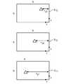
도 4는 일부 실시례에 따른 뷰어(viewer)(312)를 통한 수술 장면의 투시 뷰(perspective view)를 도시한 설명도이다. 2개의 영상 요소(imaging element)(206R, 206L)를 갖는 관찰 시스템(viewing system)이 양호한 3D 관찰 투시뷰를 제공할 수 있다. 수술 장면 내의 물리적 구조부에 대한 물리적 치수 및/또는 위치 정보를 표현하는 수치값들이 수술 장면 영상에 오버레이(overlay)되어 표시된다. 예를 들어, 수치적 거리값 "d_Instr_Trgt"이 장면 내에 기기(400)와 목표(410) 사이에 표시되어 보여진다.4 is an explanatory view showing a perspective view of a surgical scene through a
원격조종 의료 시스템Remote Control Medical System
원격조종은 일정 거리에서의 기계의 조종을 지칭한다. 최소 침습 원격조종 의료 시스템에 있어서, 외과의사는 환자의 신체 내의 수술 부위를 관찰하기 위해서 내시경에 장착된 카메라를 사용할 수 있다. 수술하는 동안 고해상도 뷰를 제공하기 위해서 3차원 영상이 만들어졌다. 일부 실시례에 따르면, 내시경 상에 장착되고, 이미저 센서 어레이를 포함하는 카메라 시스템이 정량적 3차원 정보에 더하여 3차원 영상을 생성하기 위해 사용될 수 있는 색상 및 조명 데이터를 제공한다.Remote control refers to manipulation of the machine at a certain distance. In a minimally invasive remotely operated medical system, the surgeon may use a camera mounted on the endoscope to observe the surgical site within the patient ' s body. Three-dimensional images were created to provide high-resolution views during surgery. According to some embodiments, a camera system mounted on an endoscope and including an imager sensor array provides color and illumination data that can be used to generate three-dimensional images in addition to quantitative three-dimensional information.
도 5는 일부 실시례에 따른, 하나 이상의 기계식 암(158)을 사용하여 최소 침습 수술 과정을 실생하기 위한 원격조종 수술 시스템(100)의 예시적인 블록도이다. 시스템(100)의 실시형태들은 원격 로봇식 및 자율 작동식 구조들을 포함한다. 이 기계식 암들은 종종 기기를 지지한다. 예를 들어, 기계식 수술 암(예컨대, 중심 기계식 수술 암(158C))은 Q3D 영상 센서 어레이와 관련된 내시경과 같은, 입체식 즉 3차원 수술 영상 포착 장치(101C)를 지지하는 데 사용될 수 있다. 기계식 수술 암(158C)은 상기 영상 포착 장치(101C)를 기계식 암에 기계적으로 고정시키기 위한 멸균 어댑터 또는 클램프, 클립, 스크루, 슬롯/그루브 또는 다른 파스너 기구를 포함할 수 있다. 반대로, 상기 영상 포착 장치(101C)는 기계식 수술 암(158C)과 견고하게 상호 끼워맞춤되도록 기계식 수술 암(158C)의 물리적 윤곽 및/또는 구조와 상보적인 물리적 윤곽 및/또는 구조를 포함할 수 있다.5 is an exemplary block diagram of a remote controlled
사용자 또는 오퍼레이터(O)(일반적으로 외과의사)는 마스터 제어 콘솔(150)에서 제어 입력 장치(160)를 조작함으로써 환자(P)에 대한 최소 침습 수술 과정을 실행한다. 오퍼레이터는 도 4를 참조하여 상술한 뷰어(312)를 포함하는 입체 디스플레이 장치(164)를 통해 환자의 신체 내부의 수술 부위의 영상들의 비디오 프레임들을 볼 수 있다. 콘솔(150)의 컴퓨터(151)가 제어 라인(159)을 통해 원격조종으로 제어되는 내시경 수술 기기(101A-101C)의 운동을 지시하여, 환자측 시스템(152)(환자측 카트라고도 함)을 이용하여 기기들의 운동을 실현한다.The user or operator O (typically a surgeon) performs a minimally invasive surgical procedure on the patient P by manipulating the
환자측 시스템(152)은 하나 이상의 기계식 암(158)을 포함한다. 일반적으로, 환자측 시스템(152)은 대응되는 포지셔닝 셋업 암(156)에 의해 지지되는 적어도 3개의 기계식 수술 암(158A-158C)(기계식 수술 암(158)이라 통칭됨)을 포함한다. 중심 기계식 수술 암(158C)은 카메라의 시계 내의 영상들에 대한 Q3D 정보의 취득에 적합한 내시경 카메라(101C)를 지원할 수 있다. 중심 좌우의 기계식 수술 암(158A 및 158B)은 조직을 조작할 수 있는 지지 기기(101A 및 101B)를 각각 지지할 수 있다.The
도 6은 일부 실시례에 따른 환자측 시스템(152)의 예시적인 사시도이다. 환자측 시스템(152)은 베이스(172)에 의해 지지되는 카트 칼럼(170)을 포함한다. 하나 이상의 기계식 수술 암(158)이 환자측 시스템(152)의 포지셔닝부의 일부분인 하나 이상의 셋업 암(156)에 각각 부착된다. 베이스(172)의 대략 중심 위치에, 카트 칼럼(170)은 카운터밸런스 서브시스템 및 오염 물질 차단 서브시스템의 구성요소들을 보호하는 보호 커버(180)를 포함한다.6 is an exemplary perspective view of a
모니터 암(154)을 제외하고는, 각각의 기계식 수술 암(158)은 기기(101A-101C)를 제어하는 데 사용된다. 또한, 각각의 기계식 수술 암(158)은 셋업 암(156)에 연결되고, 셋업 암(156)은 다음으로 본 발명의 하나의 실시례에 있어서 캐리지 하우징(190)에 연결된다. 하나 이상의 기계식 수술 암(158)은 도 6에 도시된 바와 같이 그들 각각의 셋업 암(156)에 의해 각각 지지된다.Except for the
기계식 수술 암(158A-158D)은 각각, 기기들을 입수하고 및 추적하는데 도움이 되는 미가공 미보정 기구학 데이터(raw uncorrected kinematics data), 기구학 데이터, 및/또는 기구학 정보를 생성하기 위해서 하나 이상의 변위 트랜스듀서, 방향 센서 및/또는 위치 센서(185)를 포함할 수 있다. 기기들도, 본 발명의 일부 실시례에 있어서, 변위 트랜스듀서, 위치 센서 및/또는 방향 센서(186)를 포함할 수 있다. 또한, 하나 이상의 기기는 기기의 취득 및 추적을 돕기 위한 마커(189)를 포함할 수 있다.Each of the mechanical
원격조종 의료 시스템에 대한 추가적인 정보는 2012년 1월 26일자로 공개된 미국 특허 출원 공개공보 제2012/0020547호에 제공되어 있다.Additional information on remote controlled medical systems is provided in United States Patent Application Publication No. 2012/0020547, published January 26,
내시경 이미저 시스템Endoscopic Imager System
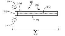
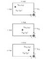
도 7a는 일부 실시례에 따른 제1 영상 포착 시스템(101C)의 설명도이다. 영상 포착 시스템(101C)은 제1 단부 부분(204), 제2 단부 부분(206) 및 제1 단부 부분(204)의 팁 부분(208)을 포함한 기다란 부분(202)을 포함하고 있는 내시경을 포함한다. 제1 단부 부분(204)은 인간의 체강 내로 삽입될 수 있는 크기로 되어 있다. 다수의 영상 센서(도시되어 있지 않음)를 포함하는 이미저 센서 어레이(210)가 제1 단부 부분(204)의 팁 부분(208)에 결합되어 있다. 기다란 부분(202)은 목표 물체가 이미저 센서 어레이(210)에 의해 영상화될 수 있도록 팁 부분(208)을 체강 내의 목표 물체에 충분히 근접하게 위치시키기에 충분한 길이를 가지고 있다. 일부 실시례에 따르면, 제2 단부 부분(206)은 기계식 암(도시되어 있지 않음)과 견고하게 상호 끼워맞춤되도록 상술한 바와 같이 물리적 윤곽 및/또는 구조(도시되어 있지 않음)를 포함할 수 있다. 기다란 부분(202)은 또한 이미저 센서 어레이(210)와 전자적으로 정보를 통신하기 위한 하나 이상의 전자 신호 경로(212)를 포함한다. 광원(214)은 영상화될 물체를 비추도록 배치되어 있다. 일부 실시례에 따르면, 광원(214)은, 예를 들어, 비구조광(unstructured light), 백색광, 색상 여과 광 또는 몇 가지 선택된 파장의 광일 수 있다.7A is an explanatory diagram of a first
도 7b는 일부 실시례에 따른 제2 영상 포착 시스템(101C')의 설명도이다. 제1 영상 포착 시스템(101C)의 실시형태와 실질적으로 동일한 제2 영상 포착 시스템(101C')의 실시형태는 동일한 참고 번호로 나타내지고, 다시 설명하지는 않는다. 로드 렌즈(rod lens)와 같은 광도파관 입력부에 대한 입력부가 제1 단부 부분(204)의 팁 부분(208)에 배치된다. 광도파관 본체는 팁 부분(208)으로부터 물리적으로 변위되어 있는 이미저 센서 어레이(210)로 광도파관이 입력될 때 수신되는 영상을 전송하도록 기다란 부분(202) 내로 뻗어 있다. 일부 실시례에 있어서, 이미저 센서 어레이(210)는 체강 내의 대상체의 관찰 중에 당해 이미저 센서 어레이(210)가 체강 외부에 배치되도록 팁 부분(208)으로부터 충분히 멀리 변위된다.FIG. 7B is an explanatory diagram of a second
도 8은 일부 실시례에 따른, 도 7a의 제1 영상 포착 시스템(101C)과 관련된 제어 블록들을 나타내고 있고, 작동중인 제1 영상 포착 시스템(101C)을 나타내고 있는 예시적인 블록도이다. 이미저 센서 어레이(210)에 의해 포착된 영상들은 데이터 버스(212)를 거쳐 비디오 프로세서(104)로 전송되고, 비디오 프로세서(104)는 버스(105)를 통해 컨트롤러(106)와 통신한다. 비디오 프로세서(104)는 카메라 제어 유닛(CCU) 및 비디오 신호 검출기(VSD) 보드를 포함할 수 있다. CCU는 밝기, 색상 계획(color scheme), 화이트밸런스 등과 같은 영상 센서(210)의 다양한 세팅을 프로그램하거나 제어한다. VSD는 영상 센서로부터 수신된 비디오 신호를 처리한다.FIG. 8 is an exemplary block diagram illustrating control blocks associated with the first
일부 실시례에 따르면, 하나 이상의 프로세서를 포함하는 프로세서 시스템이 프로세서 기능들을 실행하도록 구성된다. 일부 실시례에 있어서, 프로세서 시스템은 여기에 설명되는 프로세서 기능들을 실행하기 위해 함께 작동하도록 구성된 다수의 프로세서를 포함한다. 따라서, 하나 이상의 기능을 실행하도록 구성된 적어도 하나의 프로세서에 대한 참조는 그 기능들이 하나의 프로세서만으로 실행될 수 있거나 함께 작동하는 다수의 프로세서에 의해 실행될 수 있는 프로세서 시스템을 포함한다.According to some embodiments, a processor system including one or more processors is configured to execute processor functions. In some implementations, the processor system includes a plurality of processors configured to operate together to execute the processor functions described herein. Accordingly, reference to at least one processor configured to perform one or more functions includes a processor system in which the functions can be executed by a plurality of processors that can be executed with only one processor or with one processor.
대체 실시형태로서, CCU와 VSD는 하나의 기능 블록으로 통합될 수 있다. 하나의 실시례에 있어서, 프로세서 및 저장 장치(도시되어 있지 않음)를 포함하는 컨트롤러(106)는 기다란 부분의 팁(208)에 인접한 장면 내의 지점들의 물리적 정량적 3D 좌표를 계산하고, 3D 장면들을 합성하도록 비디오 프로세서(104) 및 3D 디스플레이 드라이버(109)의 양자 모두를 구동시키며, 상기 3D 장면들은 3D 디스플레이(110)에 표시될 수 있다. 데이터 버스(107, 108)는 비디오 프로세서(104), 컨트롤러(106) 및 디스플레이 드라이버(109) 사이에서 정보 및 제어 신호를 교환시킨다. 일부 실시례에 있어서, 이들 요소는 내시경(202)의 본체 내부에서 영상 센서 어레이(210)와 통합될 수 있다. 대체 실시형태로서, 이들 요소는 내시경의 내부 및/또는 외부에 분포될 수 있다. 내시경(202)은 목표(120)를 포함하는 수술 장면에 대한 시각적 접근을 제공하기 위해 신체 조직(130)을 침투하도록 캐뉼라(140)를 통해서 배치된 것으로 도시되어 있다. 목표(120)는 해부학적 목표, 다른 수술 기기 또는 환자의 신체 내부의 수술 장면의 임의의 다른 실시형태일 수 있다.As an alternative embodiment, the CCU and the VSD may be integrated into one functional block. In one embodiment, the
장면의 영상에 추가되는 Q3D 정보의 예Examples of Q3D information added to a scene image
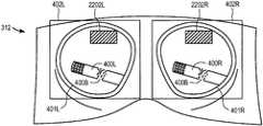
도 4를 다시 참조하면, 도 4는 일부 실시례에 따른, 도 5의 마스터 제어 콘솔(150)의 뷰어(312)의 투시 뷰(perspective view)를 도시한 설명도이다. 일부 실시례에 따르면, 3차원 투시 뷰를 제공하기 위해, 뷰어(312)는 좌측 뷰파인더(401L)와 우측 뷰파인더(401R)에 각각 임의의 기기(400)와 목표(410)를 포함하는 수술 부위의 좌측 영상(400L)과 우측 영상(400R)을 포함하는 각각의 눈에 대한 입체 영상을 포함한다. 상기 뷰파인더의 좌측 영상(400L)과 우측 영상(400R) 각각 좌측 디스플레이 장치(402L)와 우측 디스플레이 장치(402R)에 의해 제공될 수 있다. 좌측 디스플레이 장치(402L)와 우측 디스플레이 장치(402R)는 선택적으로 음극선관(CRT) 모니터, 액정 디스플레이(LCD) 또는 다른 타입의 영상 디스플레이 장치(예컨대, 플라즈마, 디지털 광투사 등)의 쌍일 수 있다. 본 발명의 바람직한 실시례에 있어서, 영상들은 컬러 CRT 또는 컬러 LCD와 같은 한 쌍의 컬러 디스플레이 장치(402L, 402R)에 의해 컬러로 제공된다. 기존 장치들과의 역방향 호환성(backward compatibility)을 지원하기 위해, 입체 디스플레이 장치(402L 및 402R)는 Q3D 시스템과 함께 사용될 수 있다. 선택적으로, Q3D 영상 시스템은 3D 모니터, 3D TV 또는 3D 효과 안경의 사용을 요구하지 않는 디스플레이와 같은 오토스테레오스코픽 디스플레이(autostereoscopic display)에 연결될 수 있다.Referring again to FIG. 4, FIG. 4 is an illustration depicting a perspective view of the
2개의 영상 요소(206R, 206L)를 가진 관찰 시스템이 양호한 3D 관찰 투시를 제공할 수 있다. Q3D 영상 시스템은 수술 장면 내의 물리적 구조부에 대한 물리적 인 치수 정보로 이 관찰 투시를 보완한다. Q3D 내시경 시스템과 함께 사용되는 입체 뷰어(312)는 수술 장면의 입체 영상 위에 오버레이되는 Q3D 정보를 표시할 수 있다. 예를 들어, 도 4에 도시된 바와 같이, 기기(400)와 목표(410) 사이의 수치적 Q3D 거리값 "d_Instr_Trgt"이 입체 뷰어(312) 내에 표시될 수 있다.An observation system with two image elements 206R, 206L can provide good 3D viewing and viewing. The Q3D imaging system complements this observation with physical dimension information about the physical structure in the surgical scene. The
수술 장면의 3차원 투시 뷰에 물리적 위치 및 치수 정보를 오버레이시키도록 사용될 수 있은 비디오 입체 관찰 시스템의 설명은 미국 특허 출원 공개공보 제2012/0020547호에 제공되어 있고, 단락 [0043] 내지 [0053] 및 대응하는 도면이 본 명세에 명확하게 포함되어 있다.A description of a video viewing system that can be used to overlay physical location and dimensional information in a three-dimensional perspective view of a surgical scene is provided in United States Patent Application Publication No. 2012/0020547 and is described in paragraphs [0043] to [0053] And corresponding drawings are explicitly included in the specification.
정량적 3차원 물리적 정보 처리Quantitative three-dimensional physical information processing
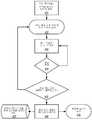
도 9는 일부 실시례에 따른, 물리적 목표의 정량적 3차원 위치를 결정하기 위한 프로세스를 나타낸 예시적인 플로우차트이다. 이 프로세스는 도 8의 실시례의 Q3D 시스템(101C)을 참조하여 설명한다. 모듈 401은 영상 센서(Sij)로부터 비디오 데이터를 취득하도록 컨트롤러(106)를 구성한다. 영상 센서 어레이(210)가 전체 시계를 "영상화"하지만, 상이한 센서들 및 상이한 센서들 내의 상이한 픽셀들은 시계 내의 상이한 대상체 지점들로부터의 영상 투영들에 의해 조명될 수 있다는 것을 알 수 있을 것이다. 비디오 데이터는, 예를 들어, 색상 및 광 강도 데이터를 포함할 수 있다. 각각의 센서의 각각의 픽셀은 그것에 투영되는 영상의 색상과 강도를 지시하는 하나 이상의 신호를 제공할 수 있다. 모듈 402는 물리적 세계 뷰(physical world view) 내의 선택된 관심 영역에서 목표들을 체계적으로 선택하도록 컨트롤러를 구성한다. 모듈 403은 초기 설정값(x0, y0, z0)을 가지고서 목표 3D 좌표(x, y, z)의 연산을 개시하도록 컨트롤러를 구성한다. 이 알고리즘은 다음으로 목표를 관찰하는 모든 센서(Sij)로부터의 영상 다이버시티 데이터(image diversity data)를 이용함으로써 일관성(consistency)에 대해 좌표들을 점검한다. 좌표 연산은 허용가능한 정밀도에 도달할 때까지 단계 404에서 정제(refine)된다. 판정 모듈 404는 현재 연산된 물리적 위치가 충분히 정확한지의 여부를 판정하도록 컨트롤러를 구성한다. 현재 연산된 위치가 충분히 정확하지 않다는 판정에 응답하여, 제어는 다른 가능한 물리적 위치를 시도하도록 모듈 403으로 되돌아간다. 현재 연산된 위치가 충분히 정확하다는 판정에 응답하여, 모듈 405는 전체 관심 영역이 스캔되었는지의 여부를 판정하도록 컨트롤러를 구성한다. 전체 관심 영역이 스캔되지 않았다는 판정에 응답하여, 제어는 모듈 402로 되돌아가고, 다른 목표가 선택된다. 전체 관심 영역이 스캔되었다는 판정에 응답하여, 제어는 모듈 406으로 진행하고, 모듈 406은 관심의 대상인 영상 모듈의 3차원 모델을 모으도록(assemble) 컨트롤러(406)를 구성한다. 목표 구조부들의 물리적 위치를 지시하는 3차원 정보에 기초한 목표의 3D 영상의 집합체(assembly)는 당업자에게 공지되어 있어 여기서 설명할 필요가 없다. 모듈 407은 이후의 검토 및 조작을 위해 다수의 목표에 대해 결정된 물리적 위치 정보를 사용하여 개발된 3차원 모형을 저장하도록 컨트롤러를 구성한다. 예를 들어, 3D 모델은 환자의 기관의 특정 치수에 대해 임플란트의 크기를 결정하는 것과 같은 수술 용처를 위해 나중에 사용될 수 있을 것이다. 또 다른 예에 있어서, 새로운 수술 기기(101)가 로봇 시스템(152)에 설치될 때, 새로운 기기에 대해 이전 수술 장면을 참조하도록 하기 위해 3D 모델을 재호출하여 모니터(110) 상에 표시하는 것이 필요할 수 있다. 모듈 408은 정량적 3D 뷰를 표시하기 위해 다수의 목표에 대해 결정된 물리적 위치 정보를 사용하도록 컨트롤러를 구성한다. Q3D 뷰의 한 예는 도 4에 도시된 거리값 "d_Instr_Trgt"이다.9 is an exemplary flow chart illustrating a process for determining a quantitative three dimensional location of a physical target, in accordance with some embodiments. This process will be described with reference to the
도 10은 일부 실시례에 따른, 대체로 도 9의 모듈 402에 대응되는 프로세스의 특정 세부 사항을 도시한 예시적인 플로우차트이다. 모듈 402.1은 센서 어레이(210)의 모든 센서로부터 물리적 세계 장면(physical world scene)의 영상들을 포착하도록 컨트롤러를 구성한다. 모듈 402.2는 포착된 장면 내로부터 관심 영역을 특정하도록 컨트롤러를 구성한다. 모듈 402.3은 동일한 목표의 투영에 의해 조명되는 상이한 센서들 내의 픽셀 위치들을 식별하기 위해 관심 영역 내의 장면 영상들 간의 최상의 정합(match)을 탐색하도록 컨트롤러를 구성한다. 후술하는 바와 같이, 최상의 정합은 시프트되는 영상과 참조 영상 간의 2차원 상호 상관 함수(two-dimensional cross-correlation function)를 최대화할 때까지 센서(Sij)로부터의 개별 영상들을 시프트시킴으로써(이에 한정되지 않음) 성취될 수 있다. 참조 영상은 예를 들면 센서(S11)로부터 수신된 장면 영상일 수 있다. 모듈 402.4는 동일한 목표로부터의 투영에 의해 조명되는 후보 픽셀들을 식별하도록 컨트롤러를 구성한다. 모듈 402.5는 후보 픽셀들이 동일한 목표로부터의 투영에 의해 조명되는지의 여부를 판정하기 위해 선택된 목표에 대해 2개 이상의 픽셀 좌표(Nx, Ny)를 연산하도록 컨트롤러를 구성한다. 판정 모듈 402.6은 연산된 2D 픽셀 좌표값들이 후보 픽셀들이 동일한 목표로부터의 투영에 의해 조명된다는 것을 지시하는지의 여부를 판정한다. 다수의 센서(Sij)로 동일한 장면을 관찰하는 것에 의해 발생되는 영상 다이버시티가 다양한 개별 영상(Sij) 내에서의 특정 목표와 관련된 (Nx, Ny)를 정확하게 식별하는 역할을 한다. 예를 들어, 일부 실시례에 따라, 단지 3개의 센서(S11, S12 및 S13)만이 사용되는 단순화된 시나리오를 가정하면, 2D 픽셀 좌표[(Nx11, Ny11), (Nx12, Ny12), (Nx13, Ny13)]의 트리플릿(triplet)이 [S11, S12 및 S13] 상으로의 동일한 목표의 투영들에 대응되지 않는 경우에는, 양(


각각의 픽셀은 색상 및 강도 정보를 세계 장면(world scene)으로부터 직접적으로 포착한다는 것이 이해될 것이다. 또한, 상기 프로세스에 따라, 각각의 픽셀은 픽셀 상으로 투영된 세계 뷰(world view) 내의 물리적 대상체의 좌표(x, y, z)와 관련된다. 따라서, 색상 정보, 조도 정보, 물리적 위치 정보 즉 색상 및 조명이 투영된 물리적 대상체의 위치는 비일시적 컴퓨터 판독가능 저장 장치 내의 픽셀과 관련될 수 있다. 아래의 표 1은 이러한 관련성을 설명한다.It will be appreciated that each pixel directly captures color and intensity information from a world scene. Also, according to the process, each pixel is associated with the coordinates (x, y, z) of the physical object in the world view projected onto the pixel. Thus, the color information, illumination information, physical location information, i.e., the location of the physical object onto which color and illumination are projected, may be associated with pixels within the non-volatile computer readable storage device. Table 1 below illustrates this relationship.
Q3D 정보를 결정하는 예An example of determining Q3D information
투영 정합(projection matching)의 예Example of Projection Matching
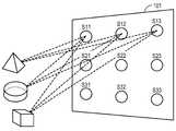
일부 실시례에 따르면, 도 11은 3개의 예시적인 대상체를 포함하고 있는 예시적인 3차원 실세계 장면을 포함하는 시계를 가지도록 배치되어 있는 복수의 센서(S11-S33)를 포함하는 하나의 예시적인 센서 이미저 어레이(210)의 설명도이다. 어레이 내의 각각의 센서는 각각의 차원으로 적어도 2개의 픽셀을 갖는 2차원 픽셀 배열부를 포함한다. 각각의 센서는 렌즈 스택을 포함하고, 렌즈 스택은 그것의 초점면 내에 배치된 대응하는 픽셀 배열부 상에 영상을 해상하는 개별적인 광 채널을 발생시킨다. 각각의 픽셀은 광 센서로서 작용하고, 다수의 픽셀을 가진 각각의 초점면은 영상 센서로서 작용한다. 그것의 초점면을 가진 각각의 센서(S11-S33)는 다른 센서들 및 초점면들에 의해 차지되는 센서 어레이의 영역과 다른 센서 어레이의 일정 영역을 차지한다. 적절한 공지된 영상 센서 어레이가 상기한 미국 특허 제8,514,491호 및 미국 특허 출원 공개공보 제2013/0070060호에 개시되어 있다.According to some embodiments, FIG. 11 illustrates one example including a plurality of sensors (S11 -S33 ) arranged to have a clock including an exemplary three-dimensional real-world scene containing three exemplary objects FIG. 4 is an explanatory diagram of the
일부 실시례에 따르면, 센서들은 Nx 및 Ny. 그들의 x 방향 및 y 방향의 픽셀들의 총 개수 및 시계각(field of view angle)(θx 및 θy)에 의해 특징지어진다. 일부 실시례에 있어서, x 축 및 y 축에 대한 센서 특성은 동일할 것으로 예상된다. 하지만, 변경된 실시례에 있어서, 센서는 비대칭적인 x 축 및 y 축 특성을 갖는다. 마찬가지로, 일부 실시례에 있어서, 모든 센서는 픽셀의 총 개수 및 동일한 시계각을 가질 것이다. 센서들은 양호하게 제어되도록 센서 어레이(210)에 걸쳐 분포된다. 예를 들어, 센서들은 도시된 2차원 격자 상에서 거리 δ만큼 이격될 수 있다. 센서 배치 피치 δ는 상기 격자 전체에 걸쳐서 대칭적이거나 비대칭적일 수 있다.According to some embodiments, the sensors are Nx and Ny . The total number of pixels in their x and y directions and the field of view angles ([theta]x and [theta]y ). In some embodiments, the sensor characteristics for the x and y axes are expected to be the same. However, in a modified embodiment, the sensor has asymmetric x-axis and y-axis characteristics. Likewise, in some embodiments, all sensors will have the same number of pixels and the same clock angle. The sensors are distributed over the
도 11에 도시된 실시례에 있어서, 센서들은 센서(S11-S13)가 상부 행을 차지하고, 센서(S21-S23)가 중간 행을 차지하고, 센서(S31-S33)가 하부 행을 차지하는 식으로 사격형 격자 내에 배열되어 있다. 각각의 센서는 N열의 픽셀 및 N행의 픽셀을 포함한다. 광원에 의해 생성된, 파선으로 표시된, 광선들이 삼각형 형상의 제1 대상체, 구 형상의 제2 대상체 및 직사각형 형상의 제3 대상체의 각각으로부터 이미저 어레이의 각각의 센서로 반사된다. 예시를 목적으로, 상부 행의 센서(S11, S12 및 S13)로의 광선들만이 도시되어 있다. 광원은 예컨대 비구조 백색광(non-structured white light) 또는 주변광일 수 있다. 대체 실시형태로서, 광원은 적외선과 같은 선택된 파장의 광을 제공할 수 있거나, 광이, 예를 들면, 선택된 색상이나 색상의 범위를 제공하도록 여과되거나 분할될 수 있다. 광선들은 마찬가지로 대상체들의 각각으로부터 센서(S21-S33)로 반사된다는 것을 알 수 있을 것이다. 하지만, 설명을 간단히 하기 위해, 이 다른 광선들은 도시되어 있지 않다.In the exemplary case shown in Figure 11, the sensors are sensors (S11 -S13) occupies a top line, a sensor (S21 -S23) occupies the middle row, the sensor (S31 -S33) the lower Are arranged in a shot grid in such a manner as to occupy rows. Each sensor includes N columns of pixels and N rows of pixels. The rays generated by the light source, indicated by the dashed lines, are reflected from each of the first object of triangular shape, the second object of spherical shape and the third object of rectangular shape to each sensor of the imager array. For purposes of illustration, only the rays to the sensors in the upper row (S11 , S12 and S13 ) are shown. The light source may be, for example, non-structured white light or ambient light. In an alternative embodiment, the light source may provide light of a selected wavelength, such as infrared, or the light may be filtered or segmented, for example, to provide a range of colors or hues selected. Rays will recognize that the reflection to the sensor (S21 -S33) from each of the target object as well. However, for simplicity of explanation, these other rays are not shown.
모듈 401과 모듈 402.1에 따르면, 센서 어레이(210)의 센서들은 세계 뷰(world view)로부터 그리고 모듈 402.1에 따라 영상들을 개별적으로 포착한다. 도 12는 일부 실시례에 따른, 3개의 대상체의 센서(Sij)(S11, S12 및 S13만 도시됨) 상으로의 투영들을 나타낸 설명도이다. 당업자는 센서들에 입사하는 반사된 광선들이 시계 내에 있는 대상체들의 영상을 투영한다는 것을 이해할 것이다. 더 구체적으로는, 이미저 어레이의 다수의 상이한 영상 센서에 입사하는 시계 내의 대상체들로부터 반사된 광선들은 3차원에서 2차원에 이르는 대상체들의 다수의 투시 투영(perspective projection) 즉 반사된 광선들을 수취하는 각각의 센서에서의 상이한 투영을 발생시킨다. 특히 대상체들의 투영들의 상대 위치는 S11으로부터 S12로, S13로 진행할 때 좌에서 우로 시프트된다. 입사 광선들에 의해 조명되는 영상 센서 픽셀들은 입사광에 응답하여 전기 신호를 생성한다. 따라서, 각각의 영상 센서마다, 그것의 픽셀들에 의해 영상 센서 내의 영상 투영의 형상 및 위치를 나타내는 반사된 광선들에 응답하여 일정 패턴의 전기 신호들이 생성된다.According to module 401 and module 402.1, the sensors of
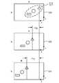
모듈 402.2에 따르면, 관심 영역이 세계 장면(world scene)으로부터 선택된다. 도 13은 장면 내에서의 관심 영역의 선택을 나타내는 설명도이다. 이 예에 있어서는, 삼각형 형상의 제1 대상체, 구 형상의 제2 대상체 및 직사각형 형상의 제3 대상체 모두가 선택된 관심 영역 내에 있다. 이 단계는 오퍼레이터로부터 입력을 수취하는 것에 의해 성취될 수 있으며, 또는 소프트웨어에 의해 소정의 방식으로 구성된 컴퓨터를 이용하여 자동적으로 또는 오퍼레이터 입력과 자동 소프트웨어 제어식 선택의 조합에 의해 실행될 수 있다. 예를 들어, 일부 실시례에 있어서, 세계 장면은 인간 해부학적 구조부의 내강(internal cavity)을 보여줄 수 있고, 대상체들은 체내 기관들이나 수술 기기들 또는 그 일부분일 수 있다. 외과의사는 내강 내로부터의 실시간 시각 영상을 받아볼 수 있으며, 인간 해부학적 구조의 조직 영역들과 체강 내에서 돌출되어 있는 수술 기기의 일부분을 자신의 시야 내에 둘 수 있다. 외과의사는, 예를 들어, 텔레스트레이션(telestration)과 같은 비디오 마커(video marker)와 같은 공지된 기술을 통하여 위치 정보가 결정될 수 있는 자신의 시야 내의 대상체들을 특정할 수 있다. 대체 실시형태로서 또는 이러한 오퍼레이터 요청에 추가하여, 에지 검출 알고리즘(edge detection algorithm)과 같은 자동화된 프로세스가 관심 영역(ROI)을 특정하는 데 사용될 수 있다.According to module 402.2, the region of interest is selected from the world scene. Fig. 13 is an explanatory diagram showing selection of a region of interest in a scene. Fig. In this example, both the triangular-shaped first object, the spherical second object, and the rectangular third object are within the selected region of interest. This step may be accomplished by receiving input from an operator, or it may be performed automatically, using a computer configured in some manner by software, or by a combination of operator input and automatic software controlled selection. For example, in some embodiments, the global scene may show an internal cavity of a human anatomical structure, and the objects may be internal organs or surgical instruments, or a portion thereof. The surgeon can receive real time visual images from within the lumen and can place tissue areas of the human anatomical structure and a portion of the surgical instrument protruding in the body cavity within his field of view. The surgeon may specify objects in his field of view where location information can be determined through known techniques, such as, for example, video markers such as telestration. As an alternative embodiment or in addition to such an operator request, an automated process, such as an edge detection algorithm, may be used to specify a region of interest (ROI).
모듈 402.3에 따르면, 동일한 목표 대상체의 투영들에 의해 조명된 상이한 센서들의 픽셀 위치들을 식별하도록 관심 영역 내의 장면 영상들 사이에서 최상의 정합이 결정된다. 도 14는 일부 실시례에 따른, 센서(S11, S12 및 S13)에 투영된 영상들의 상대적인 기하학적 오프셋 형상에 대한 추가 세부 사항을 도시한 설명도이다. 일부 실시례에 따라, 센서(S13)에서의 영상이 참조 영상(reference image)으로 간주되고, 선택된 ROI 내의 대상체들의 투영들은 센서(S13) 내에서의 그들의 위치에 대해 센서(S12) 내에서 양(σ23) 픽셀만큼 우측으로 오프셋된다. 선택된 ROI 내의 대상체들의 투영들은 센서(S13) 내에서의 그들의 위치에 대해 센서(S11) 내에서 양(σ13) 픽셀만큼 우측으로 오프셋된다.According to module 402.3, the best match is determined between scene images in the region of interest to identify the pixel locations of different sensors illuminated by the projections of the same target object. 14 is an explanatory diagram illustrating additional details on the geometric offset geometry of the images projected onto the sensors S11 , S12 and S13 , according to some embodiments. According to some embodiments, the image at the sensor S13 is considered a reference image and the projections of objects within the selected ROI are located within the sensor S12 for their position within the sensor S13 Lt; RTI ID = 0.0 > (23 ) < / RTI > The projection of the object in the selected ROI are offset to the right by an amount (σ13) of pixels in the sensor (S11) for their position within the sensor (S13).
도 15는 일부 실시례에 따른, 센서(S13) 내의 ROI 내의 투영된 영상들과 정렬되도록 우측으로 시프트된 센서(S11 및 S12) 내의 ROI 내의 투영된 영상들을 도시한 설명도이다. 현재의 예에 있어서는, 센서(S13)가 참조 센서로서 작용하도록 지정된다. 다른 센서들이 정렬 및 기하학적 치수들을 결정하는 데 사용하기 위해 선택될 수 있다는 것을 이해할 것이다. 선택된 ROI 내의 대상체들의 투영들은 예컨대 센서(S13)와 같은 지정된 센서에서 식별되고, 예컨대 센서(S11 및 S12)와 같은 다른 센서들에서의 투영들은 그들이 지정된 센서에서의 투영과 정렬될 때까지 시프트된다. 이러한 방식으로, 선택된 ROI 내의 대상체들의 대응되는 투영들이 지정된 센서 내에서의 투영들의 위치에 대한 그들의 오프셋들과 함께 다른 센서들 내에서 식별될 수 있다.15 is an explanatory diagram showing projected images in the ROI in the sensors S11 and S12 shifted to the right to align with the projected images in the ROI in the sensor S13 , according to some embodiments. In the present example, the sensor S13 is designated to act as a reference sensor. It will be appreciated that other sensors may be selected for use in determining alignment and geometric dimensions. And identified in the given sensor, such as a projection can, for example sensors (S13) of the target object in the selected ROI, for example, the projection of the other sensors, such as sensors (S11 and S12) are, until they are aligned with the projection of the specified sensor Shifted. In this manner, corresponding projections of objects in the selected ROI can be identified in different sensors with their offsets to the position of projections in the designated sensor.
구체적으로, 예를 들어, 3개의 예시의 대상체의 투영들이 센서(S12) 내에서 양(σ23) 픽셀만큼 우측으로 시프트되고, 3개의 예시의 대상체의 투영들이 센서(S11) 내에서 양(σ13) 픽셀만큼 우측으로 시프트된다. 이 설명예에 있어서는, 설명을 간단히 하기 위해, 투영들이 y 방향으로만 오프셋되고, x 방향으로는 오프셋되지 않는 것을 가정하였지만, 동일한 원리가 센서들 간의 x 방향 투영 오프셋들에도 적용된다. 또한, 이 예는 선형 오프셋들을 도시하고 있지만, 당업자는 예를 들어 다른 센서들에서 상대적인 오프셋들을 가지는 투영들을 정렬시키기 위한 회전과 같은 다른 변환들에 적용할 수 있다.Amount within Specifically, for example, of the three exemplary object projected to the sensor (S12) is shifted in the right by an amount (σ23) pixels, the three exemplary object projected to the sensor (S11) (?13 ) pixels. In this description example, for the sake of simplicity, it is assumed that the projections are offset only in the y direction and not in the x direction, but the same principle applies to the x direction projection offsets between the sensors. This example also shows linear offsets, but one skilled in the art can apply to other transforms, for example rotation, to align projections having relative offsets in other sensors.
예컨대 일부 실시례에 따라, 2차원(2D) 상호 상관 기법(cross-correlation technique)이나 주성분 분석(principal component analysis)(PCA)이 S13 내의 ROI 내의 투영들을 S12 내의 ROI 내의 투영들과 정렬시키고, S13 내의 ROI 내의 투영들을 S11 내의 ROI 내의 투영들과 정렬시키는 데 사용될 수 있다. 일반적으로, 그 의도는 센서(Sij)로부터의 영상들을 참조 센서로서 지정된 센서로부터의 영상과 최상으로 정합시키거나 정렬시키고자 하는 것이다. 더 구체적으로는, 최고 상관 계수가 성취될 때까지, S12 내의 ROI 내의 투영된 영상들이 시프트되고, S13 내의 ROI 내의 투영된 영상들과 상호 상관된다. 마찬가지로, 최고 상관 계수가 성취될 때까지, S11 내의 ROI 내의 투영된 영상들이 시프트되고, S13 내의 ROI 내의 투영된 영상들과 상호 상관된다. 따라서, ROI의 투영들의 정렬은 S13 내의 ROI 내의 투영과 S12 내의 ROI 내의 투영 사이의 오프셋을 결정하고, S13 내의 ROI 내의 투영과 S11 내의 ROI 내의 투영 사이의 오프셋을 결정함으로써, 센서(S11 및 S12) 내의 ROI의 투영들의 위치를 식별하는 데 사용된다.For example, according to some embodiments, a two-dimensional (2D) cross-correlation technique or principal component analysis (PCA) aligns the projections in the ROI within S13 with the projections in the ROI in S12 , And can be used to align the projections in the ROI in S13 with the projections in the ROI in S11 . In general, the intent is to best match or align images from sensors (Sij ) with images from sensors designated as reference sensors. More specifically, the projected images within the ROI within S12 are shifted and cross-correlated with the projected images within the ROI within S13 until the highest correlation coefficient is achieved. Likewise, the projected images within the ROI within S11 are shifted and cross-correlated with the projected images within the ROI within S13 until the highest correlation coefficient is achieved. Thus, the alignment of the projections of the ROI determines the offset between the projection in the ROI in S13 and the projection in ROI in S12 , and determines the offset between the projection in ROI in S13 and the projection in ROI in S11 , ≪ / RTI > S11 and S12 ).
후보 픽셀 선택 및 정제의 예Example of candidate pixel selection and refinement
모듈 402.4에 따르면, 후보 픽셀들이 최상의 정합 프로세스에 의해 동일한 목표로부터의 투영들에 의해 조명되는 상이한 센서들 내에서 식별된다. 일단 ROI 내의 대상체들의 투영들이 ROI 내의 센서(S11, S12 및 S13)의 각각에서 식별되면, ROI 내의 각각의 목표점들의 물리적 (x, y, z) 투영들이 이미저 어레이에 대해 결정될 수 있다. 일부 실시례에 따라, ROI 내의 다수의 목표점의 각각에 대해, 목표점으로부터의 투영에 의해 조명되는 다수의 센서의 각각의 센서 내의 하나 이상의 픽셀이 식별된다. 이러한 각각의 목표점에 대해, 물리적 (x, y, z) 목표점 위치가 적어도 부분적으로 목표점으로부터의 투영들에 의해 조명되는 것으로 결정된 상이한 센서들 내에 배치된 픽셀들 간의 기하학적 관계들에 기초하여 결정된다.According to module 402.4, candidate pixels are identified in different sensors that are illuminated by projections from the same target by the best matching process. Once the projections of objects in the ROI are identified in each of the sensors (S11 , S12 and S13 ) in the ROI, the physical (x, y, z) projections of each target point in the ROI can be determined for the array . According to some implementations, for each of a plurality of target points in the ROI, one or more pixels in each sensor of a plurality of sensors illuminated by projections from a target point are identified. For each of these target points, the physical (x, y, z) target point position is determined based at least in part on the geometric relationships between the pixels disposed in different sensors determined to be illuminated by the projections from the target point.
일정 시퀀스의 목표점들이 ROI를 체계적으로 횡단이동하는 것에 의해(예컨대 특정 단계 크기를 가지고 우측에서 좌측으로 그리고 특정 단계 크기를 가지고 위에서 아래로) 자동적으로 선택될 수 있고, 물리적 (x, y, z) 목표점 위치가 각각의 선택된 목표점에 대해 결정될 수 있다. S11 및 S12가 S13에 대해 최상으로 정합되기 때문에, 횡단이동은 시프트되는 관심 영역 내부에서 실행된다. 목표를 선택하는 것은 목표의 투영에 의해 조명되는 센서(S11, S12 및 S13)의 각각의 센서 내의 픽셀을 식별하는 것을 포함한다. 따라서, 센서(S11, S12 및 S13)의 각각의 센서 내의 후보 픽셀들은 선택된 목표점의 투영에 의해 조명되는 것으로서 식별된다.The target points of a certain sequence can be automatically selected by systematically traversing the ROI (e.g., from right to left with a particular step size and up to down with a particular step size), and physical (x, y, z) A target point position can be determined for each selected target point. Since S11 and S12 are best matched against S13 , the transverse movement is performed within the region of interest to be shifted. Selecting a target includes identifying pixels in each sensor of the sensors (S11 , S12, and S13 ) illuminated by the projection of the target. Thus, the candidate pixels in each sensor of the sensors S11 , S12 and S13 are identified as being illuminated by the projection of the selected target point.
다시 말해, 목표점(T)을 선택하기 위해, 목표점(T)의 투영에 의해 조명되는 픽셀이 센서(S11, S12 및 S13)의 각각에서 선택된다. 목표(T)의 (x, y, z) 물리적 위치는 그것의 선택의 순간에는 알려져 있지 않다는 것이 이해될 것이다. 또한, 상술한 정렬 프로세스의 부정확성이 각각의 센서 내의 어느 픽셀들이 선택된 목표(T)의 투영에 의해 조명되는지의 판정에 있어서의 부정확성을 초래할 수 있다. 따라서, 도 17, 18 및 19를 참조하여 설명되는 바와 같이, 현재 선택된 목표(T)의 투영에 의해 조명되는 센서(S11, S12 및 S13)의 각각의 센서 내의 픽셀들에 대한 판정의 정확성에 대한 추가적인 판정이 이루어진다.In other words, in order to select the target point T, a pixel illuminated by the projection of the target point T is selected in each of the sensors S11 , S12 and S13 . It will be appreciated that the (x, y, z) physical location of target (T) is not known at the moment of its selection. In addition, the inaccuracy of the alignment process described above can lead to inaccuracies in the determination of which pixels in each sensor are illuminated by the projection of the selected target T. Thus, as described with reference to Figs. 17, 18 and 19, the determination of the pixels in each sensor of the sensors S11 , S12 and S13 illuminated by the projection of the currently selected target T An additional determination of accuracy is made.
상기 예로 설명을 계속하여, 삼각형 형상의 제1 대상체가 현재 선택된 목표점이라고 가정하자. 도 16은 일부 실시례에 따른, 선택된 삼각형 형상의 목표점의 센서(S11, S12 및 S13) 상으로의 투영들을 도시한 설명도이다. 이러한 투영들로부터, 목표(T)에 대한 2D 픽셀 좌표들 [(Nx11, Ny11), (Nx12, Ny12), (Nx13, Ny13)]이 결정된다. 단순화를 위해, 도 16은 단지 y 축 픽셀 좌표들만 도시하고 있다. 이러한 2D 픽셀 좌표들을 사용하여, 식 (402.5-1) 및 (402.5-2)이 적용되고,


도 17을 참조하면, 센서(S11, S12 및 S13)를 포함하는 이미저 어레이의 일부분 및 물리적 공간 내의 위치(x, y, z)에 배치된 선택된 삼각형 형상의 제1 대상체 목표점(T)이 도시되어 있다. 이미저 어레이 내의 센서들은 그들 사이에 알려진 간격(δij)을 가지고 있다. S11과 S12 사이의 물리적 위치 간격은 δ12이고, S12과 S13 사이의 물리적 위치 간격은 δ23이이다. 일부 실시례에 있어서, 모든 센서(Sij) 사이의 이러한 간격은 δ로 동일한 구조적 사양이다. 센서(Sij)는 또한 알려진 시계각(θ)을 가지고 있다.17, a selected target object point T (x, y, z) of a selected triangular shape disposed at a portion of the imager array including sensors S11 , S12, and S13 and physical space ) Are shown. The sensors in the imager array have a known spacing (δij ) between them. The physical location spacing between S11 and S12 is δ12 , and the physical location spacing between S12 and S13 is δ23 . In some embodiments, this spacing between all sensors Sij is the same structural specification as?. The sensor Sij also has a known clock angle [theta].
전술한 바와 같이, 일부 실시례에 있어서, 각각의 센서는 사각형 패턴의 행과 열로 배열된 픽셀들을 가진 2D 촬상 소자로서 구성된다. 선택적으로, 픽셀은 예컨대 원형 패턴, 지그재그 패턴 또는 산란형 패턴 또는 서브픽셀 오프셋(sub-pixel offset)을 포함하는 불규칙 패턴으로 배열될 수 있다. 이러한 소자들의 각도 및 픽셀 특성들은 동일할 수 있으며, 또는 센서마다 상이할 수 있다. 하지만, 이러한 특성들은 알려져 있는 것으로 가정된다. 센서들이 상이할 수도 있지만, 설명을 간단히 하기 위해, 센서들은 동일한 것으로 가정된다.As described above, in some embodiments, each sensor is configured as a 2D imaging device having pixels arranged in rows and columns of a rectangular pattern. Alternatively, the pixels may be arranged in an irregular pattern including, for example, a circular pattern, a zigzag pattern or a scattered pattern or a sub-pixel offset. The angular and pixel characteristics of these elements may be the same or may be different for each sensor. However, these properties are assumed to be known. Although the sensors may be different, for simplicity of explanation, the sensors are assumed to be the same.
단순화를 위해, 모든 센서(Sij)는 N×N 픽셀을 가진다고 가정한다. 센서(S11)로부터의 거리(z)에서, 센서의 N 픽셀 폭은 FOV1으로 지시된 센서(S11)의 y 차원 시계로 확장된다. 마찬가지로, 센서(S12)로부터의 거리(z)에서, 센서(S12)의 y 차원 시계는 FOV2로 지시되어 있다. 또한, 센서(S13)로부터의 거리(z)에서, 센서(S13)의 y 차원 시계는 길이(FOV3)로 지시되어 있다. 길이 FOV1, FOV2 및 FOV3는 서로 중첩되어, 센서(S11, S12 및 S13)가 어떤 (알려지지 않은) 거리(z)에 물리적으로 위치된 목표(T)의 3원 표본추출 다이버시티(3-way sampling diversity)를 성취하는 것을 나타낸다. 물론, 이 예에서 가정된 바와 같이 센서들이 동일하게 구성된 경우, 길이 FOV1, FOV2 및 FOV3 역시 동일할 것이다. 3개의 길이 FOV1, FOV2 및 FOV3 모두가 동일한 크기를 가지고, 설명을 목적으로 마치 그들이 서로 인접하여 적층된 것처럼 묘사되어 있지만, 그들이 이미저 어레이로부터 동일한 어떤 (알려지지 않은) 거리(z)에 위치하고 있다는 점에서 동일 평면상에 위치한다는 것이 이해될 것이다.For the sake of simplicity, it is assumed that all sensors Sij have N x N pixels. At a distance z from the sensor S11 , the N pixel width of the sensor is extended to the y-dimensional clock of the sensor S11 indicated by FOV1 . Similarly, in the sensor distance (z) from the (S12), y-D clock of the sensor (S12) is indicated by FOV2. Further, in the distance (z) from the sensor (S13), y-D clock of the sensor (S13) is indicated by the length (FOV3). The lengths FOV1 , FOV2 and FOV3 are superimposed on each other so that the sensors S11, S12 and S13 can measure the ternary sampling diversity 3 of the target T physically located at some (unknown) -way sampling diversity. Of course, if the sensors are configured identically, as assumed in this example, the lengths FOV1 , FOV2 and FOV3 will also be the same. Although the three lengths FOV1 , FOV2 and FOV3 all have the same size and are depicted as if they were stacked adjacent to one another for illustrative purposes, they are at some (unknown) distance (z) It will be understood that it is located on the same plane in that it is located.
도 18을 참조하면, 현재 선택된 목표점(T)의 영상 센서(S11, S12 및 S13) 상으로의 투영의 예시적인 정면도가 도시되어 있다. 단순화를 위해, 센서들이 크기 N×N 픽셀의 기하학적 사각형 픽셀 어레이를 포함하는 것으로 가정한다. 또한, 목표(T) 투영의 x 좌표들이 모두 동일한 것으로 가정한다. 다시 말해, 목표(T)의 센서(S11, S12 및 S13) 상으로의 투영들에 대해, nx1 = nx2 = nx3인 것으로 가정한다. 설명을 간단히 하기 위해, 또한 기하학적 시계각(θ)은 수평방향일 때와 수직방향일 때가 동일한 것으로 즉 θx = θy인 것으로 가정한다. 당업자는 상기 가정들 중의 어느 것이 변경되는 경우에 목표(T)의 x, y 및 z 물리적 좌표들를 연산하기 위해 아래에 제공되는 프로세스를 어떻게 변경해야 할지를 알 것이다.Referring to Fig. 18, an exemplary front view of the projection onto the image sensors S11 , S12 and S13 of the currently selected target point T is shown. For simplicity, it is assumed that the sensors include a geometric square pixel array of size N x N pixels. It is also assumed that the x coordinates of the target (T) projection are all the same. In other words, for the projections of the target T onto the sensors S11 , S12 and S13 , it is assumed that nx1 = nx2 = nx3 . In order to simplify the explanation, it is also assumed that the geometric clock angle (?) Is the same when the horizontal direction and the vertical direction are the same, that is,?X =?Y. Those skilled in the art will know how to modify the process provided below to compute the x, y, and z physical coordinates of target (T) when any of the above assumptions are altered.
목표(T)의 하나의 영상이 영상 센서(S11)의 평면 내의 기하학적 좌표(nx1, ny1)에 위치한 센서(S11) 내의 하나의 물리적 점에 투영된다. 더 구체적으로는, 목표점(T)의 센서(S11) 상으로의 투영은 원점에서 보았을 때 y 축을 따라 ny1 픽셀에 그리고 x 축을 따라 nx1 픽셀에 위치된다. 목표(T)의 하나의 영상이 영상 센서(S12)의 평면 내의 기하학적 좌표(nx2, ny2)에 위치한 센서(S12) 내의 하나의 물리적 점에 투영된다. 목표(T)의 하나의 영상이 영상 센서(S13)의 평면 내의 기하학적 좌표(nx3, ny3)에 위치한 센서(S13) 내의 하나의 물리적 점에 투영된다. 각각의 센서 내의 픽셀 위치(nxi, nyi)는 센서에 대해 제공된 원점(0, 0) 기준 좌표에 대해 결정된다는 것이 이해될 것이다. 도 17 또는 도 19에 도시된 바와 같이, 전역 좌표계 (x, y, z)가 정의되고, 목표에 대한 기준으로 사용된다. 예를 들어, 이러한 좌표계의 원점은 센서(S11)의 기하학적 중심에 배치될 수 있다(이에 한정되지 않음).The single image of the target (T) is projected onto a single physical point in the image sensor of the sensor (S11) located on the geometric coordinates (nx1, ny1) in a plane of a (S11). More specifically, the projection onto the sensor (S11) of the target point (T) is along the y-axis as seen from the origin point to the pixel ny1 andx1 are located in the n pixels along the x-axis. One image of the target T is projected onto one physical point in the sensor S12 located at the geometric coordinates nx2 , ny2 in the plane of the image sensor S12 . One image of the target T is projected onto one physical point in the sensorS13 located at the geometric coordinates nx3 and ny3 in the plane of the image sensor S13 . It will be appreciated that the pixel location (nxi , ny i ) in each sensor is determined for the origin (0, 0) reference coordinates provided for the sensor. As shown in Fig. 17 or 19, a global coordinate system (x, y, z) is defined and used as a reference for the target. For example, the origin of this coordinate system may be located in the geometric center of the sensor (S11) (without limitation).
도 16과 도 18을 함께 참조하면, 목표의 투영의 y 픽셀 거리가 각각의 센서에서 상이하다는 것을 알 수 있다. 현재 선택된 목표(T)의 투영은 S11에서 원점의 좌측으로 ny1 픽셀에 위치된다. 현재 선택된 목표(T)의 투영은 S12에서 원점의 좌측으로 ny2 픽셀에 위치된다. 현재 선택된 목표(T)의 투영은 S13에서 원점의 좌측으로 ny3 픽셀에 위치된다. 전술한 바와 같이, 설명을 간단히 하기 위해, 목표의 투영은 모든 3개의 센서에서 원점으로부터 동일한 x 픽셀 거리에 위치하는 것으로 가정한다.16 and 18, it can be seen that the y pixel distance of the projection of the target is different in each sensor. The projection of the currently selected target T is located at ny1 pixels to the left of the origin at S11 . The projection of the currently selected target T is located at ny2 pixels to the left of the origin at S12 . The projection of the currently selected target T is located at ny3 pixels to the left of the origin atS13 . As described above, to simplify the explanation, it is assumed that the projection of the target is located at the same x pixel distance from the origin in all three sensors.
도 19를 참조하면, 도 17을 참조하여 상술한 바와 같은 현재 선택된 목표(T)의 센서(S11, S12 및 S13)에 대한 배치가 도시되어 있고, 또한 각각의 센서 내의 후보 픽셀에 대한 y 방향 픽셀 오프셋들을 도시하고 있다. 도 19의 도면은 선택된 목표점(T)의 (x, y, z) 물리적 좌표들을 결정하기 위한 물리적 구조 및 분석틀을 제공한다. 이미저 어레이 평면으로부터의 (알려지지 않은) 거리(z)에서, 각각의 센서에 대한 y 방향 시계는 FOVi로 표기된 길이에 걸쳐 확장된다. 이 길이 FOVi는 일부 실시례에 있어서 N 픽셀인 센서의 최대 픽셀 폭에 대응된다. 센서가 x 및 y 방향으로 대칭인 시계를 가진다는 작동상의 가정을 고려하면, 그 길이는 x 축을 따라 수직방향으로도 FOVi일 것이다.19, the arrangement for the sensors S11 , S12 and S13 of the currently selected target T as described above with reference to FIG. 17 is shown, and also for the candidate pixels in each sensor and y-direction pixel offsets. The diagram of FIG. 19 provides a physical structure and an analysis framework for determining the (x, y, z) physical coordinates of the selected target point T. FIG. At a distance (z) (unknown) from the imager array plane, the y-directional clock for each sensor extends over the length denoted FOVi . This length FOVi corresponds to the maximum pixel width of the sensor, which in some embodiments is N pixels. Considering the operational assumption that the sensor has a clock that is symmetrical in the x and y directions, its length will be FOVi also in the vertical direction along the x axis.
후보 픽셀 선택이 적어도 부분적으로 선택된 목표의 물리적 위치의 결정에 있어서의 부정확성을 초래할 수 있는 정도의 불확실성을 가질 수 있는 상관 프로세스에 기초하여 이루어진다는 점을 상기하자. 따라서, 일부 실시례에 따라, 목표 투영 후보 선택의 정확성의 추가적인 점검이 아래와 같이 이루어진다.Recall that a candidate pixel selection is made based on a correlation process that may have an uncertainty that may result in inaccuracies in determining the physical location of the at least partially selected target. Thus, in accordance with some embodiments, an additional check of the accuracy of the target projection candidate selection is made as follows.
목표의 물리적 (x, y) 위치 결정 및 목표 투영 후보 선택의 정확성 점검의 예Examples of physical (x, y) positioning of targets and correctness checking of target projection candidates selection
모듈 402.5에 따라, 후보 픽셀들이 실제로 동일한 목표로부터의 투영에 의해 조명되는지의 여부를 판정하기 위해, 2개 이상의 2차원 (Nx, Ny) 좌표값이 선택된 목표에 대해 연산된다. 상술한 가정들에 기초하여, 3D 좌표계의 원점을 센서(S11)의 중심에 두면, 도 19의 예의 이미저 어레이 및 현재 선택된 목표(T)는 다음의 관계들을 가진다.According to module 402.5, two or more two-dimensional (Nx , Ny ) coordinate values are computed for the selected target to determine whether the candidate pixels are actually illuminated by projection from the same target. Based on the above assumptions, leaving the origin of the 3D coordinate system in the center of the sensor (S11), Example imager array and the target (T) are selected in Figure 19 have the following relationship.

여기서:here:
N은 영상 센서들의 픽셀 치수이고;N is the pixel dimension of the image sensors;
nx1은 목표점(T)의 S11 평면의 원점으로부터의 픽셀의 개수로 표현되는 x 방향의 위치이고;nx1 is a position in the x direction expressed by the number of pixels from the origin of the S11 plane of the target point T;
ny1은 목표점(T)의 S11 평면의 원점으로부터의 픽셀의 개수로 표현되는 y 방향의 위치이고;ny1 is a position in the y direction represented by the number of pixels from the origin of the S11 plane of the target point T;
nx2는 목표점(T)의 S12 평면의 원점으로부터의 픽셀의 개수로 표현되는 x 방향의 위치이고;nx2 is a position in the x direction expressed by the number of pixels from the origin of the S12 plane of the target point T;
ny2는 목표점(T)의 S12 평면의 원점으로부터의 픽셀의 개수로 표현되는 y 방향의 위치이며;ny2 is a position in the y direction expressed by the number of pixels from the origin of the S12 plane of the target point T;
θ는 시계각이다.θ is the clock angle.
또한, 센서(S11 및 S13)를 사용하여 동일 수식을 실행하는 경우, S11과 S13 사이의 간격이 2δ인 것을 고려하면, 다음의 관계식을 얻는다.When the same equations are executed using the sensors S11 and S13 , the following relation is obtained in consideration of the fact that the interval between S11 and S13 is 2δ.

여기서:here:
nx3는 목표점(T)의 S13 평면의 원점으로부터의 픽셀의 개수로 표현되는 x 방향의 위치이고;nx3 is a position in the x direction expressed by the number of pixels from the origin of the S13 plane of the target point T;
ny3는 목표점(T)의 S13 평면의 원점으로부터의 픽셀의 개수로 표현되는 y 방향의 위치이다.ny3 is a position in the y direction expressed by the number of pixels from the origin of the S13 plane of the target point T.
따라서, 선택된 목표(T)의 물리적 x 좌표의 결정은 식 (3) 또는 (6)에 기초하여 결정될 수 있다. 선택된 목표(T)의 물리적 y 좌표의 결정은 식 (2) 또는 (5)에 기초하여 결정될 수 있다. 선택된 목표(T)의 물리적 z 좌표의 결정은 식 (1) 또는 (4)에 기초하여 결정될 수 있다.Thus, the determination of the physical x-coordinate of the selected target T can be determined based on equation (3) or (6). The determination of the physical y-coordinate of the selected target T can be determined based on equation (2) or (5). The determination of the physical z-coordinate of the selected target T can be determined based on equation (1) or (4).
더 일반적으로는, 모듈 402.6에 따라, 연산된 2D 좌표값들이 후보 픽셀들이 동일한 목표로부터의 투영에 의해 조명된다는 것을 지시하는지의 여부의 판정이 이루어진다. 목표(T)의 물리적 (x, y, z) 좌표들의 보다 신뢰성 있는 판정은 각각의 좌표에 대한 2개의 수식의 사용을 통해 얻어질 수 있다는 것이 이해될 것이다. 예를 들어, 목표(T)에 대한 y 좌표는 양 수식 (2) 및 (5)를 사용하여 결정될 수 있다. 2개의 수식을 사용하여 연산된 결과의 y 좌표값들이 특정의 허용가능한 공차 값(

x 및 y 축 둘레의 센서 대칭성을 상정하면, 당업자는 동종의 판정이 ny1 대신 nx1을 사용하여 수식 (2) 및 (5)와 유사한 수식들을 이용하여 목표(T)의 x 좌표들에 대해 이루어질 수 있다. 수식 (3) 및 (6)은 z 좌표의 지식을 요구하기 때문에 모듈 402.5 및 모듈 402.6의 부분에 사용될 수 없다. 하지만, 모듈 402.5 및 모듈 402.6의 본질은 센서(S11, S12 및 S13)의 평면들로의 정확한 목표 투영들을 판정하는 것이다. 이를 위해, x 및 y 축에 대해 조정된 수식 (2) 및 (5)가 충분하다. 후술하는 바와 같이, 완벽한 세트의 좌표 (x, y, z)는 모듈 403 및 모듈 404의 연산분이다.Assuming the sensor symmetry of the x and y axis, one of ordinary skill in the art the determination of the same type by using the ny1 instead of nx1 using similar formulas with Formula (2) and (5) for the x-coordinate of the target (T) Lt; / RTI > Equations (3) and (6) can not be used in the parts of module 402.5 and module 402.6 because they require knowledge of z coordinates. However, the nature of module 402.5 and module 402.6 is to determine the correct target projections to the planes of sensors S11 , S12 and S13 . To this end, equations (2) and (5) adjusted for the x and y axes are sufficient. As described below, the complete set of coordinates (x, y, z) is the sum of the operations of
목표의 물리적 z 위치 결정의 예Example of determining the physical z position of a target
도 19에 도시된 바와 같이, 모듈 403 및 모듈 404에 따라, z 좌표에 대한 초기 추정값 z0가 연산 프로세스를 시작하는 데 사용된다. 이 초기값은 의료 적용처에 따라 자동적으로 정해진다. 의료 적용처는 시각화될 의도된 세계 뷰(intended world view)를 한정한다. 초기값 z0는 내시경에 가정 근접한 시계의 가장자리에서 시작한다. 도 8을 참조하면, 내시경적 절제술을 포함하는 Q3D 적용처에 대해, z0는 예컨대 Q3D 내시경(202)의 원위 단부(208)로부터 1-5mm 떨어진 곳일 수 있다. 이러한 초기 추정값은 일반적으로 임의의 조직이나 수술 기기가 Q3D 내시경에 그와 같이 밀접해 있을 가능성이 적기 때문에 이러한 적용처에 대해 충분하다. 다음으로, 값 z0가 수식 (3) 및 (6)에 대입된다. 목표의 x 좌표가 유일한 것을 고려하면, z0가 목표의 실제의 정확한 z 좌표이면, 수식 (3) 및 (6)은 동일한 값 또는 허용가능한 수준의 공차(

수식 (3)과 (6)의 산출값이 허용가능한 공차(
상기 설명은 설명을 이유로 단순화되었고, 따라서 3개의 센서(S11, S12 및 S13)만을 포함하였다. 일반적으로는, Q3D 좌표 연산의 정확성을 증가시키면서 또한 전체 반복의 수를 감소시키기 위해 더 많은 센서가 사용될 수 있다. 예를 들어, 3개보다 더 많은 센서, 바람직하게는 3×3 센서 어레이가 사용되면, 최급 구배(steepest gradient)와 같은 방법들이 모듈 402.5 및 모듈 403에 의해 만들어지는 추정값 오차들의 방향성의 추세를 결정하는 데 채용될 수 있다. 그러면, 반복 단계 크기 및 방향이 3D 오차 구배면의 국소적 극단을 향한 진행과 조화되도록 조정될 수 있다.The above description has been simplified for the sake of explanation, and thus includes only three sensors S11 , S12 and S13 . In general, more sensors can be used to increase the accuracy of the Q3D coordinate operation and also to reduce the total number of iterations. For example, if more than three sensors, preferably a 3x3 sensor array, are used, methods such as the steepest gradient determine the trend of the directionality of the estimation errors produced by module 402.5 and
Q3D 정보에 의한 내시경 수술 가이드Endoscopic surgery guide by Q3D information
도 20은 일부 실시례에 따른 수술 과정 중에 Q3D 정보를 사용하기 위한 제1 프로세스(2000)를 나타낸 예시적인 플로우차트이다. 컴퓨터 프로그램 코드는 프로세스(2000)를 실행하도록 컴퓨터(151)를 구성한다. 모듈 2002는 뷰어(312)를 들여다 볼 때의 외과의사의 시계 내의 적어도 2개의 대상체를 선택하기 위한 사용자 입력을 수신하도록 컴퓨터를 구성한다. 모듈 2004는 사용자 선택의 수신에 응답하여 컴퓨터 콘솔 상에 메뉴를 표시하도록 컴퓨터를 구성한다. 판정 모듈 2006은 메뉴에 대한 사용자 입력이 거리를 표시하기 위해 수신되는지의 여부를 판정하도록 컴퓨터를 구성한다. 사용자 입력이 거리를 표시하기 위해 수신된다는 판정에 응답하여, 모듈 2008은 외과의사의 시계 내의 비디오 영상 내에 수치 거리를 표시하도록 컴퓨터를 구성한다. 판정 모듈 2010은 거리 표시를 선택하기 위한 사용자 입력의 수신을 위한 규정된 시간 간격 동안 대기하고, '타임 아웃(time out)' 간격 내에서의 사용자 입력의 미수신에 응답하여 판정 모듈 2006의 동작을 종료하도록 컴퓨터를 구성한다.20 is an exemplary flow chart illustrating a
판정 모듈 2012는 메뉴에 대한 사용자 입력이 근접 경보 한계를 입력하기 위해 수신되는지의 여부를 판정하도록 시스템을 구성한다. 사용자 입력이 근접도 임계값을 입력하기 위해 수신된다는 판정에 응답하여, 모듈 2014는 외과의사의 시계 내의 2개 이상의 대상체 사이의 근접도를 모니터하기 위한 Q3D 정보를 사용하도록 컴퓨터를 구성한다. 판정 모듈 2016은 근접도 임계값이 초과되었는지의 여부를 판정한다. 근접도 임계값이 초과되었다는 판정에 응답하여, 모듈 2018은 경보를 발동하도록 컴퓨터를 구성한다. 경보는 소리, 깜빡이는 불빛과 같은 시각적 큐(visual queue), 또는 충돌을 회피하기 위한 기기 운동의 잠금을 포함할 수 있다. 근접도 임계값이 초과되지 않았다는 판정에 응답하여, 제어는 다시 모니터 모듈 2014로 되돌아간다. 판정 모듈 2020은 근접도 임계값을 입력하기 위한 사용자 입력의 수신을 위한 규정된 시간 간격 동안 대기하고, '타임 아웃(time out)' 간격 내에서의 사용자 입력의 미수신에 응답하여 판정 모듈 2012의 동작을 종료하도록 컴퓨터를 구성한다.The
도 21은 일부 실시례에 따른, 도 20의 프로세스에 따라 디스플레이 스크린(2012) 상에 표시되는 메뉴 선택을 도시한 설명도이다. 디스플레이 스크린(2102)은 컴퓨터(151)와 관련된 관찰 모니터를 포함한다. 선택적으로, 디스플레이 스크린(2102)은 뷰어(312)의 영상 요소(206R, 206L)의 영역을 포함할 수 있다. 사용자 입력에 응답하여, 모듈 2004는 제1 메뉴 항목 '거리 표시'(2106) 및 제2 메뉴 항목 '근접 경보 설정'(2108)을 포함하는 메뉴(2104)의 표시를 일으킨다. '거리 표시' 메뉴 항목(2106)을 선택하는 사용자 입력에 응답하여, 모듈 2008은 2개 이상의 대상체 간의 Q3D 거리의 표시를 일으킨다. 도 4를 다시 참조하면, 모듈 2008을 사용하여 표시된 기기(400)와 목표 사이의 Q3D 거리 "d_Instr_Trgt"의 표시가 도시되어 있다. '근접 경보 설정' 메뉴 항목(2108)을 선택하는 사용자 입력에 응답하여, 그 안에 사용자가 근접도 거리 임계값, 예를 들면, "xxxx 밀리미터"를 입력할 수 있은 필드를 포함하는 '거리 입력' UI 입력부(2110)가 표시된다. 하나의 대안적인 실시례(도시되지 않음)에 있어서는, 디폴트 근접도 임계값(default proximity threshold)이 모든 기기에 대해 미리 설정될 수 있고, 사용자는 예를 들어 도 21의 메뉴를 사용하여 근접도 임계값를 변경할 수 있다. 이 대안적인 실시례에 있어서, 사용자는 임계값을 입력하는 대신 디폴트 임계값을 고르도록 선택할 수 있다. 일부 실시례에 있어서, 사용자는 거리를 표시하고 근접 경보를 설정하는 것을 모두 선택할 수 있다.Fig. 21 is an explanatory diagram illustrating menu selection displayed on
22a-22b는 일부 실시례에 따른, 도 20의 프로세스에 따라 사용자 입력을 수신하는 것의 특정 세부 사항들을 나타낸 설명도들이다. 도 22a는 텔레스트레이션(telestration)과 같은 비디오 마커 툴(video marker tool)을 사용하거나 도 5의 제어 입력 장치(160)를 조작하는 외과의사 콘솔을 사용하여 생성될 수 있는, 신체 조직과 같은 목표(410L, 410R)의 예시의 제1 하이라이팅 영역(first highlighting area)(2202L, 2202R)을 도시하고 있다. 도 22b는 비디오 마커 툴(video marker tool)을 사용하여 생성될 수 있는 기기 팁(400L, 400R)의 예시의 제2 하이라이팅 영역(2206L, 2206R)을 도시하고 있다. 일부 실시례에 따른 작동에 있어서, 사용자는 제1 하이라이팅 영역(2202L, 2202R)을 생성한다. 다음으로, 사용자는 비디오 마커 툴를 사용하여 기기 팁(400L, 400R)의 예시의 제2 하이라이팅 영역(2206L, 2206R)을 생성한다. 항목들이 하이라이트되는 순서는 중요하지 않다는 것이 이해될 것이다. 사용자는 다음으로 선택을 입력하기 위한 선택기(selector)(도시 암됨)를 작동시킨다(예컨대, Enter 키를 누른다). 모듈 2002는 수신된 사용자 입력을 목표 영상(410L, 410R) 및 기기 영상(400L, 400R)의 선택으로서 해석한다.22a-22b are explanatory diagrams illustrating certain details of receiving user input in accordance with the process of Fig. 20, in accordance with some embodiments. FIG. 22A illustrates an example of a target, such as a body tissue, that may be generated using a video marker tool, such as telestration, or using a surgeon console operating the
도 23은 일부 실시례에 따른, 수술 과정 중에 Q3D 정보를 사용하기 위한 제2 프로세스(2300)를 나타낸 예시적인 플로우차트이다. 컴퓨터 프로그램 코드는 프로세스(2300)를 실행하도록 컴퓨터(151)를 구성한다. 모듈 2302은 뷰어(312)를 들여다 볼 때의 외과의사의 시계 내의 적어도 대상체를 선택하기 위한 사용자 입력을 수신하도록 컴퓨터를 구성한다. 예를 들어, 도 22b를 다시 참조하면, 사용자 입력은 비디오 마커 툴을 사용하여 기기 팁(400L, 400R)의 제2 하이라이팅 영역(2206L, 2206R)을 생성하도록 수신된다. 사용자 입력(도시되지 않음)은 기기 팁(400L, 400R)의 영상의 선택을 입력하기 위한 선택기(도시 안됨)를 작동시키도록 수신된다(예컨대, Enter 키를 누른다).23 is an exemplary flow chart illustrating a second process 2300 for using Q3D information during the surgical procedure, in accordance with some embodiments. The computer program code configures the
다시 한번 도 23으로 돌아가면, 사용자 선택의 수신에 응답하여, 모듈 2304는 컴퓨터 콘솔 상에 메뉴를 표시하도록 컴퓨터를 구성한다. 판정 모듈 2306은 메뉴에 대한 사용자 입력이 선택된 대상체의 영상을 회전시키도록 수신되는지의 여부를 판정하도록 컴퓨터를 구성한다. 사용자 입력이 영상을 회전시키도록 수신된다는 판정에 응답하여, 모듈 2308은 대상체의 다른 3차원 투시를 보여주기 위해 영상의 회전을 표시하도록 컴퓨터를 구성한다. 판정 모듈 2310은 영상을 회전시키기 위한 사용자 입력의 수신을 위한 규정된 시간 간격 동안 대기하고, '타임 아웃(time out)' 간격 내에서의 사용자 입력의 미수신에 응답하여 판정 모듈 2306의 동작을 종료하도록 컴퓨터를 구성한다.Returning again to Figure 23, in response to receiving the user selection, the module 2304 configures the computer to display a menu on the computer console. The
도 24는 일부 실시례에 따른, 도 23의 프로세스에 따라 디스플레이 스크린(2402) 상에 표시되는 메뉴 선택을 도시한 설명도이다. 디스플레이 스크린(2402)은 컴퓨터(151)와 관련된 관찰 모니터를 포함한다. 선택적으로, 디스플레이 스크린(2402)은 뷰어(312)의 영상 요소(206R, 206L)의 영역을 포함할 수 있다. 사용자 입력에 응답하여, 모듈 2304는 제3 메뉴 항목 '좌회전'(2406) 및 제4 메뉴 항목 '우회전'(2408)을 포함하는 메뉴(2404)의 표시를 일으킨다. 제3 메뉴 항목 또는 제4 메뉴 항목(2406 또는 2408) 중의 일방 또는 타방을 선택하는 사용자 입력에 응답하여, 모듈 2308은 도 9의 모듈 407에 따라 생성되어 저장된 3D 모델의 회전을 일으킨다. 이미저 센서 어레이(210)가 제한된 전체 시계를 가지기 때문에, 회전의 양은 어느 정도의 각도, 예컨대 30도 미만으로 제한될 수 있다는 것을 이해할 것이다.Fig. 24 is an explanatory diagram illustrating menu selection displayed on the
본 발명에 따른 실시례들의 전술한 설명 및 도면들은 단지 본 발명의 원리를 예시하는 것이다. 따라서, 다양한 변형들이 첨부된 청구범위에서 한정되는 본 발명의 기술사상 및 범위를 벗어남이 없이 당업자에 의해 상기 실시례들에 이루어질 수 있음을 이해할 것이다.The foregoing description and drawings of embodiments according to the present invention are merely illustrative of the principles of the present invention. It will therefore be appreciated that various modifications may be made to the embodiments by those skilled in the art without departing from the spirit and scope of the invention as defined in the appended claims.
Claims (32)
Translated fromKorean상기 내시경에 인접한 시야를 나타내기 위해서 배치된 영상 센서 어레이로서, 각각의 센서가 다른 센서의 픽셀 어레이로부터 분리되어 있는 픽셀 어레이를 포함하고 있는, 상기 영상 센서 어레이; 그리고
상기 시야를 비추도록 배치된 광원;
을 포함하는 것을 특징으로 하는 장치.Endoscope;
An image sensor array disposed to exhibit a field of view adjacent to the endoscope, wherein each sensor comprises a pixel array separated from a pixel array of the other sensor; And
A light source arranged to illuminate the field of view;
Lt; / RTI >
상기 광원이 비-구조형 광만 방출하는 것을 특징으로 하는 장치.The method according to claim 1,
Wherein the light source emits only non-structured light.
상기 광원이 백색광을 방출하는 것을 특징으로 하는 장치.The method according to claim 1,
Wherein the light source emits white light.
상기 내시경이 제1 단부 부분 및 제1 단부 부분의 반대쪽에 있는 제2 단부 부분을 가지고 있는 기다란 부분을 포함하고 있고;
상기 영상 센서 어레이가 제1 단부 부분에 인접하게 배치되어 있는 것을 특징으로 하는 장치.The method according to claim 1,
The endoscope including an elongate portion having a first end portion and a second end portion opposite the first end portion;
Wherein the image sensor array is disposed adjacent a first end portion.
상기 내시경이 제1 단부 부분 및 제1 단부 부분의 반대쪽에 있는 제2 단부 부분을 가지고 있는 기다란 부분을 포함하고 있고;
상기 영상 센서 어레이가 제1 단부 부분에 인접하게 배치되어 있고; 그리고
상기 광원이 백색광을 방출하는 것을 특징으로 하는 장치.The method according to claim 1,
The endoscope including an elongate portion having a first end portion and a second end portion opposite the first end portion;
The image sensor array being disposed adjacent a first end portion; And
Wherein the light source emits white light.
상기 내시경이 제1 단부 부분 및 제1 단부 부분의 반대쪽에 있는 제2 단부 부분을 가지고 있는 기다란 부분을 포함하고 있고;
상기 영상 센서 어레이가 제1 단부 부분으로부터 변위되어 배치되어 있고;
제1 단부 부분에 인접한 시야로부터 제1 단부 부분으로부터 변위된 영상 센서 어레이로 영상을 전송하도록 배치된 광도파관을 더 포함하는 것을 특징으로 하는 장치.The method according to claim 1,
The endoscope including an elongate portion having a first end portion and a second end portion opposite the first end portion;
The image sensor array being displaced from a first end portion;
Further comprising an optical waveguide disposed to transmit an image from the first end portion to a displaced image sensor array from a field of view adjacent the first end portion.
상기 내시경이 제1 단부 부분을 가지고 있는 기다란 부분을 포함하고 있고;
상기 영상 센서 어레이가 제1 단부 부분에 인접하게 배치되어 있고; 그리고
상기 기다란 부분의 제1 단부 부분의 반대쪽에 있는 내시경의 단부가 기계적인 수술용 암과 기계적인 결합을 하도록 구성되어 있는 것을 특징으로 하는 장치.The method according to claim 1,
The endoscope comprising an elongate portion having a first end portion;
The image sensor array being disposed adjacent a first end portion; And
Wherein an end of the endoscope opposite the first end portion of the elongate portion is configured to mechanically engage the mechanical surgical arm.
상기 내시경이 제1 단부 부분 및 제1 단부 부분의 반대쪽에 있는 제2 단부 부분을 가지고 있는 기다란 부분을 포함하고 있고;
상기 영상 센서 어레이가 제1 단부 부분으로부터 변위되어 배치되어 있고; 그리고
제2 단부 부분이 기계적인 수술용 암과 기계적인 결합을 하기에 적합하고;
제1 단부 부분에 인접한 시야로부터 제1 단부 부분으로부터 변위된 영상 센서 어레이로 영상을 전송하도록 배치된 광도파관을 더 포함하는 것을 특징으로 하는 장치.The method according to claim 1,
The endoscope including an elongate portion having a first end portion and a second end portion opposite the first end portion;
The image sensor array being displaced from a first end portion; And
The second end portion being adapted for mechanical engagement with a mechanical surgical arm;
Further comprising an optical waveguide disposed to transmit an image from the first end portion to a displaced image sensor array from a field of view adjacent the first end portion.
영상 센서 어레이를 이용하여 포착된 영상 정보에 기초하여 목표 물체의 3차원 위치를 결정하도록 구성된 컨트롤러를 더 포함하는 것을 특징으로 하는 장치.The method according to claim 1,
Further comprising a controller configured to determine a three-dimensional position of the target object based on the captured image information using the image sensor array.
목표 물체의 3차원 위치가 확인된 픽셀과 영상 센서 어레이의 물리적인 특성 사이의 픽셀-거리 관계에 적어도 부분적으로 기초하여 결정되는 것을 특징으로 하는 장치.10. The method of claim 9,
Wherein the three-dimensional location of the target object is determined based at least in part on the pixel-distance relationship between the identified pixels and the physical characteristics of the image sensor array.
상기 컨트롤러가 동일한 목표 물체로부터의 투영에 의해 비추어지는 영상 센서 어레이의 복수의 영상 센서의 각각의 영상 센서의 픽셀을 확인하도록 구성되어 있는 것을 특징으로 하는 장치.10. The method of claim 9,
Wherein the controller is configured to identify pixels of each image sensor of a plurality of image sensors of the image sensor array that are illuminated by projection from the same target object.
픽셀을 확인하는 것이 영상 센서 어레이의 복수의 어레이의 각각의 어레이의 동일한 목표 물체의 영상 투영을 매칭시키는 것을 포함하는 것을 특징으로 하는 장치.12. The method of claim 11,
Wherein identifying the pixels comprises matching an image projection of the same target object in each array of the plurality of arrays of image sensor arrays.
상기 컨트롤러가 동일한 목표 물체로부터의 투영에 의해 비추어지는 복수의 영상 센서의 각각의 영상 센서의 픽셀을 확인하도록 구성되어 있고;
픽셀을 확인하는 것이 복수의 영상 센서의 각각의 영상 센서의 동일한 목표 물체의 영상 투영을 매칭시키기 위해 상관 과정을 이용하는 것을 포함하고;
3차원 위치를 결정하는 것이 적어도 세 개의 확인된 픽셀의 상대 위치에 적어도 부분적으로 기초하여 적어도 하나의 치수로 목표 물체의 예상 위치를 결정하는 것을 포함하고; 그리고
허용가능한 공차보다 더 크게 다른 결정된 예상 위치에 대응하여, 영상 투영의 매칭을 개선하기 위해서 상기 상관 과정을 반복하는 것을 특징으로 하는 장치.10. The method of claim 9,
The controller being configured to identify pixels of each image sensor of a plurality of image sensors illuminated by projection from the same target object;
Wherein identifying the pixels comprises using a correlation process to match an image projection of the same target object of each image sensor of the plurality of image sensors;
Determining a three-dimensional position includes determining an expected position of the target object with at least one dimension based at least in part on the relative position of at least three identified pixels; And
And repeating the correlation process to improve the image projection matching, corresponding to other determined expected positions that are greater than the allowable tolerances.
상기 컨트롤러가 동일한 목표 물체로부터의 투영에 의해 비추어지는 복수의 영상 센서의 각각의 영상 센서의 픽셀을 확인하도록 구성되어 있고;
픽셀을 확인하는 것이 복수의 영상 센서의 각각의 영상 센서의 동일한 목표 물체의 영상 투영을 매칭시키기 위해 상관 과정을 이용하는 것을 포함하고;
3차원 위치를 결정하는 것이 적어도 세 개의 확인된 픽셀의 상대 위치에 기초하여 센서의 평면과 대체로 평행한 적어도 하나의 물리적인 치수로 목표 물체의 예상 위치를 결정하는 것을 포함하고; 그리고
허용가능한 공차 내로 매칭되는 결정된 예상 위치에 대응하여, 적어도 하나의 물리적인 치수의 목표 물체의 결정된 물리적인 위치에 적어도 부분적으로 기초하여 센서의 평면과 대체로 수직인 적어도 하나의 다른 물리적인 치수로 목표 물체의 예상 물리적인 위치를 결정하는 것을 특징으로 하는 장치.10. The method of claim 9,
The controller being configured to identify pixels of each image sensor of a plurality of image sensors illuminated by projection from the same target object;
Wherein identifying the pixels comprises using a correlation process to match an image projection of the same target object of each image sensor of the plurality of image sensors;
Wherein determining the three-dimensional position comprises determining an expected position of the target object with at least one physical dimension substantially parallel to the plane of the sensor based on the relative position of at least three identified pixels; And
At least one other physical dimension substantially perpendicular to the plane of the sensor based at least in part on the determined physical location of the at least one physical dimension of the target object, corresponding to a determined expected location that matches within an acceptable tolerance, Gt; of: < / RTI >
광원으로 목표 물체를 비추는 것을 포함하는 것을 특징으로 하는 방법.The method comprising: providing an image sensor array adjacent an end of an endoscope, wherein each sensor of the image sensor array is separated from a pixel array of the other sensor; And
And illuminating the target object with the light source.
상기 광원이 비-구조형 광만 방출하는 것을 특징으로 하는 방법.16. The method of claim 15,
Characterized in that the light source emits only non-structured light.
상기 광원이 백색광을 방출하는 것을 특징으로 하는 방법.16. The method of claim 15,
Wherein the light source emits white light.
목표 물체의 3차원 위치를 결정하는 것을 특징으로 하는 방법.16. The method of claim 15,
Wherein the three-dimensional position of the target object is determined.
목표 물체의 3차원 위치를 결정하는 것이 확인된 픽셀과 확인된 픽셀의 시야 사이의 거리 관계에 적어도 부분적으로 기초하여 결정하는 것을 포함하는 것을 특징으로 하는 방법.16. The method of claim 15,
Wherein determining a three-dimensional position of the target object comprises determining based at least in part on the distance relationship between the identified pixel and the identified pixel's view.
광원으로 목표를 비추는 것; 그리고
광도파관을 이용하여 광도파관의 입력부의 시야 내의 영상을 영상 센서 어레이로 전송하는 것을 포함하고 있고, 상기 영상 센서 어레이의 각각의 센서가 다른 센서의 픽셀 어레이로부터 분리되어 있는 픽셀 어레이를 포함하는 것을 특징으로 하는 방법.Providing an optical waveguide having an input adjacent the end of the endoscope;
Illuminating a target with a light source; And
Characterized in that it comprises transmitting an image in the field of view of the input section of the optical waveguide to the image sensor array using an optical waveguide and wherein each sensor of the image sensor array is separated from the pixel array of the other sensor Lt; / RTI >
상기 광원이 비-구조형 광만 방출하는 것을 특징으로 하는 방법.21. The method of claim 20,
Characterized in that the light source emits only non-structured light.
상기 광원이 백색광을 방출하는 것을 특징으로 하는 방법.21. The method of claim 20,
Wherein the light source emits white light.
목표 물체의 3차원 위치를 결정하는 것을 특징으로 하는 방법.21. The method of claim 20,
Wherein the three-dimensional position of the target object is determined.
목표 물체의 3차원 위치를 결정하는 것이 확인된 픽셀과 확인된 픽셀의 시야 사이의 거리 관계에 적어도 부분적으로 기초하여 결정하는 것을 포함하는 것을 특징으로 하는 방법.21. The method of claim 20,
Wherein determining a three-dimensional position of the target object comprises determining based at least in part on the distance relationship between the identified pixel and the identified pixel's view.
상기 장면에 근접하게 내시경을 삽입하는 것;
비-구조형 가시광선으로 상기 장면을 비추는 것; 그리고
정량적인 3차원 영상 센서로부터 정량적인 3차원 영상 데이터를 수신하고 처리하는 것;
을 포함하는 것을 특징으로 하는 내시경 수술 장면으로부터 정량적인 3차원 시각 정보를 제공하는 방법.A method of providing quantitative three-dimensional visual information from an endoscopic surgical scene,
Inserting the endoscope close to the scene;
Illuminating the scene with non-structured visible light; And
Receiving and processing quantitative three-dimensional image data from a quantitative three-dimensional image sensor;
Dimensional visual information from the endoscopic surgery scene.
근접 임계값 정보를 수신하는 것;
상기 장면으로부터 관심이 있는 적어도 두 개의 물체를 확인하는 입력을 수신하는 것; 그리고
근접 임계값 미만의 적어도 두 개의 물체 사이의 거리에 대응하여 경보를 제공하는 것;
을 더 포함하는 것을 특징으로 하는 내시경 수술 장면으로부터 정량적인 3차원 시각 정보를 제공하는 방법.26. The method of claim 25,
Receiving proximity threshold information;
Receiving an input identifying at least two objects of interest from the scene; And
Providing an alert corresponding to a distance between at least two objects below the proximity threshold;
Dimensional visual information from the endoscopic surgery scene.
상기 장면으로부터 목표 구역을 확인하는 입력을 수신하는 것;
정량적인 3차원 영상 데이터의 적어도 일부를 이용하여 목표 물체의 3차원 모델을 만드는 것; 그리고
상기 3차원 모델의 모습을 그래픽적으로 조작하는 사용자 입력을 수신하는 것;
을 더 포함하는 것을 특징으로 하는 내시경 수술 장면으로부터 정량적인 3차원 시각 정보를 제공하는 방법.26. The method of claim 25,
Receiving an input identifying a target area from the scene;
Creating a three-dimensional model of the target object using at least some of the quantitative three-dimensional image data; And
Receiving a user input graphically manipulating the shape of the three-dimensional model;
Dimensional visual information from the endoscopic surgery scene.
수신된 사용자 입력이 상기 3차원 모델의 모습의 방향을 바꾸는 것을 특징으로 하는 내시경 수술 장면으로부터 정량적인 3차원 시각 정보를 제공하는 방법.28. The method of claim 27,
Wherein the received user input changes a direction of a shape of the three-dimensional model.
정량적인 3차원 영상 센서가 구비된 적어도 하나의 내시경;
비-구조형 가시광선을 제공하는 광원;
정량적인 3차원 영상 정보를 생성하기 위해 정량적인 3차원 영상 센서로부터 수신된 영상 데이터를 처리하도록 구성된 프로세서; 그리고
정량적인 3차원 영상 정보를 나타내는 관찰 시스템;
을 포함하는 것을 특징으로 하는 수술 시스템.As a surgical system,
At least one endoscope having a quantitative three-dimensional image sensor;
A light source providing non-structured visible light;
A processor configured to process image data received from a quantitative three-dimensional image sensor to generate quantitative three-dimensional image information; And
An observation system that displays quantitative three-dimensional image information;
Gt; a < / RTI > surgical system.
디스플레이가 하나 이상의 오토스테레오스코픽 3차원 디스플레이로 이루어지는 것을 특징으로 하는 수술 시스템.30. The method of claim 29,
Wherein the display comprises one or more autostereoscopic three-dimensional displays.
근접 임계값을 확인하는 수단;
수술 장면으로부터 관심이 있는 적어도 두 개의 물체를 확인하는 수단; 그리고
확인된 근접 임계값 미만의 적어도 두 개의 확인된 물체 사이의 거리에 대응하여 경보를 제공하는 수단;
을 더 포함하는 것을 특징으로 하는 수술 시스템.30. The method of claim 29,
Means for identifying a proximity threshold;
Means for identifying at least two objects of interest from the surgical scene; And
Means for providing an alert corresponding to a distance between at least two identified objects less than the identified proximity threshold;
≪ / RTI >
수술 장면 내의 목표 물체를 확인하는 수단;
목표 물체의 3차원 모델을 생성하는 컴퓨터 실행가능 명령어를 포함하는 비-일시적 컴퓨터 판독가능 저장 장치; 그리고
상기 3차원 모델의 모습을 그래픽적으로 조작하는 수단;
을 더 포함하는 것을 특징으로 하는 수술 시스템.30. The method of claim 29,
Means for identifying a target object in a surgical scene;
A non-transitory computer readable storage device comprising computer executable instructions for generating a three-dimensional model of a target object; And
Means for graphically manipulating the shape of the three-dimensional model;
≪ / RTI >
Applications Claiming Priority (3)
| Application Number | Priority Date | Filing Date | Title |
|---|---|---|---|
| US201461971749P | 2014-03-28 | 2014-03-28 | |
| US61/971,749 | 2014-03-28 | ||
| PCT/US2015/023210WO2015149040A1 (en) | 2014-03-28 | 2015-03-28 | Quantitative three-dimensional imaging of surgical scenes |
Publications (2)
| Publication Number | Publication Date |
|---|---|
| KR20160138232Atrue KR20160138232A (en) | 2016-12-02 |
| KR102397254B1 KR102397254B1 (en) | 2022-05-12 |
Family
ID=54196482
Family Applications (1)
| Application Number | Title | Priority Date | Filing Date |
|---|---|---|---|
| KR1020167029885AActiveKR102397254B1 (en) | 2014-03-28 | 2015-03-28 | Quantitative three-dimensional imaging of surgical scenes |
Country Status (6)
| Country | Link |
|---|---|
| US (1) | US10368054B2 (en) |
| EP (1) | EP3125806B1 (en) |
| JP (2) | JP2017518147A (en) |
| KR (1) | KR102397254B1 (en) |
| CN (1) | CN106456252B (en) |
| WO (1) | WO2015149040A1 (en) |
Families Citing this family (65)
| Publication number | Priority date | Publication date | Assignee | Title |
|---|---|---|---|---|
| US11792538B2 (en) | 2008-05-20 | 2023-10-17 | Adeia Imaging Llc | Capturing and processing of images including occlusions focused on an image sensor by a lens stack array |
| US8866920B2 (en) | 2008-05-20 | 2014-10-21 | Pelican Imaging Corporation | Capturing and processing of images using monolithic camera array with heterogeneous imagers |
| EP2502115A4 (en) | 2009-11-20 | 2013-11-06 | Pelican Imaging Corp | CAPTURE AND IMAGE PROCESSING USING A MONOLITHIC CAMERAS NETWORK EQUIPPED WITH HETEROGENEOUS IMAGERS |
| US8878950B2 (en) | 2010-12-14 | 2014-11-04 | Pelican Imaging Corporation | Systems and methods for synthesizing high resolution images using super-resolution processes |
| US20130070060A1 (en)* | 2011-09-19 | 2013-03-21 | Pelican Imaging Corporation | Systems and methods for determining depth from multiple views of a scene that include aliasing using hypothesized fusion |
| CN104081414B (en) | 2011-09-28 | 2017-08-01 | Fotonation开曼有限公司 | Systems and methods for encoding and decoding light field image files |
| US20140002674A1 (en) | 2012-06-30 | 2014-01-02 | Pelican Imaging Corporation | Systems and Methods for Manufacturing Camera Modules Using Active Alignment of Lens Stack Arrays and Sensors |
| PL4296963T3 (en) | 2012-08-21 | 2025-04-28 | Adeia Imaging Llc | Method for depth detection in images captured using array cameras |
| WO2014032020A2 (en) | 2012-08-23 | 2014-02-27 | Pelican Imaging Corporation | Feature based high resolution motion estimation from low resolution images captured using an array source |
| US8866912B2 (en) | 2013-03-10 | 2014-10-21 | Pelican Imaging Corporation | System and methods for calibration of an array camera using a single captured image |
| US9578259B2 (en) | 2013-03-14 | 2017-02-21 | Fotonation Cayman Limited | Systems and methods for reducing motion blur in images or video in ultra low light with array cameras |
| US10122993B2 (en) | 2013-03-15 | 2018-11-06 | Fotonation Limited | Autofocus system for a conventional camera that uses depth information from an array camera |
| US9497429B2 (en) | 2013-03-15 | 2016-11-15 | Pelican Imaging Corporation | Extended color processing on pelican array cameras |
| US9438888B2 (en) | 2013-03-15 | 2016-09-06 | Pelican Imaging Corporation | Systems and methods for stereo imaging with camera arrays |
| US9898856B2 (en) | 2013-09-27 | 2018-02-20 | Fotonation Cayman Limited | Systems and methods for depth-assisted perspective distortion correction |
| US10119808B2 (en) | 2013-11-18 | 2018-11-06 | Fotonation Limited | Systems and methods for estimating depth from projected texture using camera arrays |
| WO2015081279A1 (en) | 2013-11-26 | 2015-06-04 | Pelican Imaging Corporation | Array camera configurations incorporating multiple constituent array cameras |
| US10089740B2 (en) | 2014-03-07 | 2018-10-02 | Fotonation Limited | System and methods for depth regularization and semiautomatic interactive matting using RGB-D images |
| KR102373714B1 (en) | 2014-03-28 | 2022-03-15 | 인튜어티브 서지컬 오퍼레이션즈 인코포레이티드 | Quantitative three-dimensional imaging of surgical scenes from multiport perspectives |
| WO2015149043A1 (en) | 2014-03-28 | 2015-10-01 | Dorin Panescu | Quantitative three-dimensional imaging and printing of surgical implants |
| WO2015149044A1 (en) | 2014-03-28 | 2015-10-01 | Dorin Panescu | Surgical system with haptic feedback based upon quantitative three-dimensional imaging |
| CN106456267B (en) | 2014-03-28 | 2020-04-03 | 直观外科手术操作公司 | Quantitative 3D visualization of instruments in the field of view |
| US11116383B2 (en)* | 2014-04-02 | 2021-09-14 | Asensus Surgical Europe S.à.R.L. | Articulated structured light based-laparoscope |
| JP2017531976A (en) | 2014-09-29 | 2017-10-26 | フォトネイション ケイマン リミテッド | System and method for dynamically calibrating an array camera |
| JP2017099616A (en)* | 2015-12-01 | 2017-06-08 | ソニー株式会社 | Surgical control device, surgical control method and program, and surgical system |
| US20170280970A1 (en)* | 2016-03-31 | 2017-10-05 | Covidien Lp | Thoracic endoscope for surface scanning |
| US10052163B2 (en)* | 2016-07-19 | 2018-08-21 | Hcl Technologies Limited | Assisting a surgeon to operate a surgical device |
| WO2018097831A1 (en) | 2016-11-24 | 2018-05-31 | Smith Joshua R | Light field capture and rendering for head-mounted displays |
| WO2019127539A1 (en)* | 2017-12-29 | 2019-07-04 | Shenzhen United Imaging Healthcare Co., Ltd. | Systems and methods for determining region of interest in medical imaging |
| WO2019127385A1 (en) | 2017-12-29 | 2019-07-04 | Shenzhen United Imaging Healthcare Co., Ltd. | Systems and methods for patient positioning |
| US11071591B2 (en) | 2018-07-26 | 2021-07-27 | Covidien Lp | Modeling a collapsed lung using CT data |
| US11705238B2 (en) | 2018-07-26 | 2023-07-18 | Covidien Lp | Systems and methods for providing assistance during surgery |
| CN112584741B (en)* | 2018-08-20 | 2024-10-29 | 富士胶片株式会社 | Medical image processing system |
| JP7427654B2 (en)* | 2018-09-17 | 2024-02-05 | オーリス ヘルス インコーポレイテッド | Systems and methods for performing associated medical procedures |
| US10623660B1 (en) | 2018-09-27 | 2020-04-14 | Eloupes, Inc. | Camera array for a mediated-reality system |
| CA3116287A1 (en) | 2018-10-15 | 2020-04-23 | Mazor Robotics Ltd. | Versatile multi-arm robotic surgical system |
| US11172184B2 (en) | 2018-12-13 | 2021-11-09 | Covidien Lp | Systems and methods for imaging a patient |
| US11617493B2 (en) | 2018-12-13 | 2023-04-04 | Covidien Lp | Thoracic imaging, distance measuring, surgical awareness, and notification system and method |
| US11801113B2 (en)* | 2018-12-13 | 2023-10-31 | Covidien Lp | Thoracic imaging, distance measuring, and notification system and method |
| EP3973540A1 (en) | 2019-05-23 | 2022-03-30 | Intuitive Surgical Operations, Inc. | Systems and methods for generating workspace volumes and identifying reachable workspaces of surgical instruments |
| US12089902B2 (en) | 2019-07-30 | 2024-09-17 | Coviden Lp | Cone beam and 3D fluoroscope lung navigation |
| US11270110B2 (en) | 2019-09-17 | 2022-03-08 | Boston Polarimetrics, Inc. | Systems and methods for surface modeling using polarization cues |
| WO2021071992A1 (en) | 2019-10-07 | 2021-04-15 | Boston Polarimetrics, Inc. | Systems and methods for augmentation of sensor systems and imaging systems with polarization |
| US12283062B2 (en) | 2019-11-14 | 2025-04-22 | Asensus Surgical Us, Inc. | Method and system for providing surgical site measurement |
| DE112020005932T5 (en) | 2019-11-30 | 2023-01-05 | Boston Polarimetrics, Inc. | SYSTEMS AND METHODS FOR SEGMENTATION OF TRANSPARENT OBJECTS USING POLARIZATION CHARACTERISTICS |
| US12002571B2 (en)* | 2019-12-30 | 2024-06-04 | Cilag Gmbh International | Dynamic surgical visualization systems |
| EP4081933A4 (en) | 2020-01-29 | 2024-03-20 | Intrinsic Innovation LLC | Systems and methods for characterizing object pose detection and measurement systems |
| US11797863B2 (en) | 2020-01-30 | 2023-10-24 | Intrinsic Innovation Llc | Systems and methods for synthesizing data for training statistical models on different imaging modalities including polarized images |
| US10949986B1 (en)* | 2020-05-12 | 2021-03-16 | Proprio, Inc. | Methods and systems for imaging a scene, such as a medical scene, and tracking objects within the scene |
| US11953700B2 (en) | 2020-05-27 | 2024-04-09 | Intrinsic Innovation Llc | Multi-aperture polarization optical systems using beam splitters |
| EP4171890B1 (en) | 2020-06-30 | 2025-08-13 | Mazor Robotics Ltd. | Time-spaced robotic reference frames |
| WO2022054428A1 (en)* | 2020-09-10 | 2022-03-17 | オリンパス株式会社 | Medical system and control method |
| US12274525B2 (en) | 2020-09-29 | 2025-04-15 | Mazor Robotics Ltd. | Systems and methods for tracking anatomical motion |
| US12069227B2 (en) | 2021-03-10 | 2024-08-20 | Intrinsic Innovation Llc | Multi-modal and multi-spectral stereo camera arrays |
| US12020455B2 (en) | 2021-03-10 | 2024-06-25 | Intrinsic Innovation Llc | Systems and methods for high dynamic range image reconstruction |
| US11954886B2 (en) | 2021-04-15 | 2024-04-09 | Intrinsic Innovation Llc | Systems and methods for six-degree of freedom pose estimation of deformable objects |
| US11290658B1 (en) | 2021-04-15 | 2022-03-29 | Boston Polarimetrics, Inc. | Systems and methods for camera exposure control |
| US12067746B2 (en) | 2021-05-07 | 2024-08-20 | Intrinsic Innovation Llc | Systems and methods for using computer vision to pick up small objects |
| US12175741B2 (en) | 2021-06-22 | 2024-12-24 | Intrinsic Innovation Llc | Systems and methods for a vision guided end effector |
| US12340538B2 (en) | 2021-06-25 | 2025-06-24 | Intrinsic Innovation Llc | Systems and methods for generating and using visual datasets for training computer vision models |
| US12172310B2 (en) | 2021-06-29 | 2024-12-24 | Intrinsic Innovation Llc | Systems and methods for picking objects using 3-D geometry and segmentation |
| US11689813B2 (en) | 2021-07-01 | 2023-06-27 | Intrinsic Innovation Llc | Systems and methods for high dynamic range imaging using crossed polarizers |
| US12293535B2 (en) | 2021-08-03 | 2025-05-06 | Intrinsic Innovation Llc | Systems and methods for training pose estimators in computer vision |
| US12128571B2 (en)* | 2021-10-15 | 2024-10-29 | eBots Inc. | 3D computer-vision system with variable spatial resolution |
| US12261988B2 (en) | 2021-11-08 | 2025-03-25 | Proprio, Inc. | Methods for generating stereoscopic views in multicamera systems, and associated devices and systems |
Citations (1)
| Publication number | Priority date | Publication date | Assignee | Title |
|---|---|---|---|---|
| JP2006305332A (en)* | 2005-03-28 | 2006-11-09 | Hiroshima Industrial Promotion Organization | Image processor and endoscope using the same |
Family Cites Families (158)
| Publication number | Priority date | Publication date | Assignee | Title |
|---|---|---|---|---|
| US1005215A (en) | 1911-05-16 | 1911-10-10 | Anton Hofacker | Sleigh attachment for vehicles. |
| JPH04176429A (en) | 1990-11-09 | 1992-06-24 | Olympus Optical Co Ltd | Endoscope |
| JP3217386B2 (en) | 1991-04-24 | 2001-10-09 | オリンパス光学工業株式会社 | Diagnostic system |
| US5417210A (en) | 1992-05-27 | 1995-05-23 | International Business Machines Corporation | System and method for augmentation of endoscopic surgery |
| US5603318A (en) | 1992-04-21 | 1997-02-18 | University Of Utah Research Foundation | Apparatus and method for photogrammetric surgical localization |
| AT399647B (en) | 1992-07-31 | 1995-06-26 | Truppe Michael | ARRANGEMENT FOR DISPLAYING THE INTERIOR OF BODIES |
| JPH06160087A (en) | 1992-11-20 | 1994-06-07 | Matsushita Electric Ind Co Ltd | Distance measuring method using image and its apparatus |
| US5860934A (en) | 1992-12-21 | 1999-01-19 | Artann Corporation | Method and device for mechanical imaging of breast |
| JPH07240945A (en) | 1994-02-25 | 1995-09-12 | Matsushita Electric Ind Co Ltd | Virtual space generation and presentation device |
| JP3599854B2 (en) | 1995-10-09 | 2004-12-08 | オリンパス株式会社 | Medical face-mounted video display |
| US6346940B1 (en) | 1997-02-27 | 2002-02-12 | Kabushiki Kaisha Toshiba | Virtualized endoscope system |
| JPH11309A (en)* | 1997-06-12 | 1999-01-06 | Hitachi Ltd | Image processing device |
| JP2958458B1 (en)* | 1998-08-26 | 1999-10-06 | 防衛庁技術研究本部長 | Multi-view image sensor |
| JP2000149017A (en) | 1998-11-17 | 2000-05-30 | Sony Corp | Image processing device, method and supply medium thereof |
| US6659939B2 (en) | 1998-11-20 | 2003-12-09 | Intuitive Surgical, Inc. | Cooperative minimally invasive telesurgical system |
| US6522906B1 (en) | 1998-12-08 | 2003-02-18 | Intuitive Surgical, Inc. | Devices and methods for presenting and regulating auxiliary information on an image display of a telesurgical system to assist an operator in performing a surgical procedure |
| US7343195B2 (en) | 1999-05-18 | 2008-03-11 | Mediguide Ltd. | Method and apparatus for real time quantitative three-dimensional image reconstruction of a moving organ and intra-body navigation |
| US6503195B1 (en) | 1999-05-24 | 2003-01-07 | University Of North Carolina At Chapel Hill | Methods and systems for real-time structured light depth extraction and endoscope using real-time structured light depth extraction |
| US6517478B2 (en) | 2000-03-30 | 2003-02-11 | Cbyon, Inc. | Apparatus and method for calibrating an endoscope |
| US6468203B2 (en) | 2000-04-03 | 2002-10-22 | Neoguide Systems, Inc. | Steerable endoscope and improved method of insertion |
| JP2002024807A (en) | 2000-07-07 | 2002-01-25 | National Institute Of Advanced Industrial & Technology | Object motion tracking method and recording medium |
| JP4451968B2 (en) | 2000-07-11 | 2010-04-14 | Hoya株式会社 | 3D image input device |
| US6650927B1 (en) | 2000-08-18 | 2003-11-18 | Biosense, Inc. | Rendering of diagnostic imaging data on a three-dimensional map |
| JP2002171537A (en) | 2000-11-30 | 2002-06-14 | Canon Inc | Compound eye imaging system, imaging device, and electronic device |
| DE10138537B4 (en) | 2001-08-06 | 2006-07-06 | Siemens Ag | Tactile feedback to visualize tissue elasticity |
| US8175680B2 (en) | 2001-11-09 | 2012-05-08 | Boston Scientific Scimed, Inc. | Systems and methods for guiding catheters using registered images |
| JP3751568B2 (en) | 2002-02-21 | 2006-03-01 | 株式会社サタケ | Air jet diagnostic device for endoscope |
| US9155544B2 (en) | 2002-03-20 | 2015-10-13 | P Tech, Llc | Robotic systems and methods |
| JP3927487B2 (en) | 2002-12-02 | 2007-06-06 | 株式会社大野興業 | Manufacturing method of artificial bone model |
| FR2855292B1 (en) | 2003-05-22 | 2005-12-09 | Inst Nat Rech Inf Automat | DEVICE AND METHOD FOR REAL TIME REASONING OF PATTERNS ON IMAGES, IN PARTICULAR FOR LOCALIZATION GUIDANCE |
| JP4414682B2 (en) | 2003-06-06 | 2010-02-10 | オリンパス株式会社 | Ultrasound endoscope device |
| DE10340546B4 (en) | 2003-09-01 | 2006-04-20 | Siemens Ag | Method and apparatus for visually assisting electrophysiology catheter application in the heart |
| JP2005087468A (en) | 2003-09-17 | 2005-04-07 | Shoji Kawahito | Image pickup device provided with distance image measurement function and endoscopic apparatus |
| JP4229791B2 (en) | 2003-09-19 | 2009-02-25 | 真 金子 | Endoscope device |
| US7746377B2 (en) | 2003-11-28 | 2010-06-29 | Topcon Corporation | Three-dimensional image display apparatus and method |
| US7901348B2 (en) | 2003-12-12 | 2011-03-08 | University Of Washington | Catheterscope 3D guidance and interface system |
| DE102004008164B3 (en) | 2004-02-11 | 2005-10-13 | Karl Storz Gmbh & Co. Kg | Method and device for creating at least a section of a virtual 3D model of a body interior |
| US7289106B2 (en) | 2004-04-01 | 2007-10-30 | Immersion Medical, Inc. | Methods and apparatus for palpation simulation |
| US20050254720A1 (en) | 2004-05-17 | 2005-11-17 | Kar-Han Tan | Enhanced surgical visualizations with multi-flash imaging |
| JP2006109939A (en) | 2004-10-12 | 2006-04-27 | Chinontec Kk | Endoscope apparatus |
| WO2006070669A1 (en) | 2004-12-27 | 2006-07-06 | Olympus Corporation | Medical image processing apparatus, and medical image processing method |
| US20100312129A1 (en) | 2005-01-26 | 2010-12-09 | Schecter Stuart O | Cardiovascular haptic handle system |
| JP4625964B2 (en) | 2005-01-28 | 2011-02-02 | 国立大学法人佐賀大学 | 3D image detector |
| US7752920B2 (en) | 2005-12-30 | 2010-07-13 | Intuitive Surgical Operations, Inc. | Modular force sensor |
| WO2006114369A2 (en)* | 2005-04-27 | 2006-11-02 | Obducat Ab | Means for transferring a pattern to an object |
| US8073528B2 (en)* | 2007-09-30 | 2011-12-06 | Intuitive Surgical Operations, Inc. | Tool tracking systems, methods and computer products for image guided surgery |
| US9789608B2 (en) | 2006-06-29 | 2017-10-17 | Intuitive Surgical Operations, Inc. | Synthetic representation of a surgical robot |
| US9492240B2 (en) | 2009-06-16 | 2016-11-15 | Intuitive Surgical Operations, Inc. | Virtual measurement tool for minimally invasive surgery |
| US8108072B2 (en) | 2007-09-30 | 2012-01-31 | Intuitive Surgical Operations, Inc. | Methods and systems for robotic instrument tool tracking with adaptive fusion of kinematics information and image information |
| US9289267B2 (en) | 2005-06-14 | 2016-03-22 | Siemens Medical Solutions Usa, Inc. | Method and apparatus for minimally invasive surgery using endoscopes |
| CA2620196A1 (en) | 2005-08-24 | 2007-03-01 | Traxtal Inc. | System, method and devices for navigated flexible endoscopy |
| JP2009507617A (en) | 2005-09-14 | 2009-02-26 | ネオガイド システムズ, インコーポレイテッド | Method and apparatus for performing transluminal and other operations |
| US8079950B2 (en) | 2005-09-29 | 2011-12-20 | Intuitive Surgical Operations, Inc. | Autofocus and/or autoscaling in telesurgery |
| WO2007047782A2 (en) | 2005-10-20 | 2007-04-26 | Intuitive Surgical, Inc | Auxiliary image display and manipulation on a computer display in a medical robotic system |
| US7907166B2 (en) | 2005-12-30 | 2011-03-15 | Intuitive Surgical Operations, Inc. | Stereo telestration for robotic surgery |
| DE102006002001B4 (en) | 2006-01-16 | 2009-07-23 | Sensomotoric Instruments Gmbh | Method for determining the spatial relation of an eye of a person with respect to a camera device |
| IL181470A (en) | 2006-02-24 | 2012-04-30 | Visionsense Ltd | Method and system for navigating within a flexible organ of the body of a patient |
| US20070236514A1 (en) | 2006-03-29 | 2007-10-11 | Bracco Imaging Spa | Methods and Apparatuses for Stereoscopic Image Guided Surgical Navigation |
| US8246680B2 (en) | 2006-05-25 | 2012-08-21 | Spinemedica, Llc | Patient-specific spinal implants and related systems and methods |
| US9718190B2 (en) | 2006-06-29 | 2017-08-01 | Intuitive Surgical Operations, Inc. | Tool position and identification indicator displayed in a boundary area of a computer display screen |
| GB0613576D0 (en)* | 2006-07-10 | 2006-08-16 | Leuven K U Res & Dev | Endoscopic vision system |
| US7728868B2 (en) | 2006-08-02 | 2010-06-01 | Inneroptic Technology, Inc. | System and method of providing real-time dynamic imagery of a medical procedure site using multiple modalities |
| EP2054852B1 (en) | 2006-08-21 | 2010-06-23 | STI Medical Systems, LLC | Computer aided analysis using video from endoscopes |
| US7824328B2 (en) | 2006-09-18 | 2010-11-02 | Stryker Corporation | Method and apparatus for tracking a surgical instrument during surgery |
| US8496575B2 (en) | 2006-11-14 | 2013-07-30 | Olympus Corporation | Measuring endoscope apparatus, program and recording medium |
| US20090189749A1 (en) | 2006-11-17 | 2009-07-30 | Salada Mark A | Haptic Interface Device and Method for Using Such |
| WO2008076910A1 (en) | 2006-12-15 | 2008-06-26 | The Board Of Trustees Of The Leland Stanford Junior University | Image mosaicing systems and methods |
| DE602006019314D1 (en) | 2006-12-15 | 2011-02-10 | Ao Technology Ag | DEVICE FOR THE COMPUTER-BASED DISTAL LOCKING OF LABELS |
| US8672836B2 (en) | 2007-01-31 | 2014-03-18 | The Penn State Research Foundation | Method and apparatus for continuous guidance of endoscopy |
| EP1952752B2 (en) | 2007-01-31 | 2019-10-16 | Richard Wolf GmbH | Endoscope system |
| US20100281370A1 (en) | 2007-06-29 | 2010-11-04 | Janos Rohaly | Video-assisted margin marking for dental models |
| US20090076476A1 (en) | 2007-08-15 | 2009-03-19 | Hansen Medical, Inc. | Systems and methods employing force sensing for mapping intra-body tissue |
| FR2920085B1 (en) | 2007-08-24 | 2012-06-15 | Univ Grenoble 1 | IMAGING SYSTEM FOR THREE-DIMENSIONAL OBSERVATION OF AN OPERATIVE FIELD |
| US20090133260A1 (en) | 2007-11-26 | 2009-05-28 | Ios Technologies, Inc | 3D dental shade matching and apparatus |
| US20100111389A1 (en) | 2007-12-06 | 2010-05-06 | Siemens Medical Solutions Usa, Inc. | System and method for planning and guiding percutaneous procedures |
| US20090157059A1 (en) | 2007-12-14 | 2009-06-18 | Searete Llc, A Limited Liability Corporation Of The State Of Delaware | Surgical instrument navigation system |
| JP2009204991A (en)* | 2008-02-28 | 2009-09-10 | Funai Electric Co Ltd | Compound-eye imaging apparatus |
| US20090221908A1 (en) | 2008-03-01 | 2009-09-03 | Neil David Glossop | System and Method for Alignment of Instrumentation in Image-Guided Intervention |
| DE102008018636B4 (en) | 2008-04-11 | 2011-01-05 | Storz Endoskop Produktions Gmbh | Device and method for endoscopic 3D data acquisition |
| US8866920B2 (en) | 2008-05-20 | 2014-10-21 | Pelican Imaging Corporation | Capturing and processing of images using monolithic camera array with heterogeneous imagers |
| DK3876510T3 (en) | 2008-05-20 | 2024-11-11 | Adeia Imaging Llc | CAPTURE AND PROCESSING OF IMAGES USING MONOLITHIC CAMERA ARRAY WITH HETEROGENEOUS IMAGES |
| US8636653B2 (en)* | 2008-06-09 | 2014-01-28 | Capso Vision, Inc. | In vivo camera with multiple sources to illuminate tissue at different distances |
| EP2145575A1 (en) | 2008-07-17 | 2010-01-20 | Nederlandse Organisatie voor toegepast-natuurwetenschappelijk Onderzoek TNO | A system, a method and a computer program for inspection of a three-dimensional environment by a user |
| US8334900B2 (en) | 2008-07-21 | 2012-12-18 | The Hong Kong University Of Science And Technology | Apparatus and method of optical imaging for medical diagnosis |
| JP5435916B2 (en)* | 2008-09-18 | 2014-03-05 | 富士フイルム株式会社 | Electronic endoscope system |
| JP4702569B2 (en) | 2008-09-30 | 2011-06-15 | マツダ株式会社 | Image processing apparatus for vehicle |
| JP2012505695A (en) | 2008-10-20 | 2012-03-08 | コーニンクレッカ フィリップス エレクトロニクス エヌ ヴィ | Image-based localization method and system |
| US8594841B2 (en) | 2008-12-31 | 2013-11-26 | Intuitive Surgical Operations, Inc. | Visual force feedback in a minimally invasive surgical procedure |
| US9978288B2 (en) | 2009-02-13 | 2018-05-22 | University Of Florida Research Foundation, Inc. | Communication and skills training using interactive virtual humans |
| US8690776B2 (en) | 2009-02-17 | 2014-04-08 | Inneroptic Technology, Inc. | Systems, methods, apparatuses, and computer-readable media for image guided surgery |
| US9017334B2 (en) | 2009-02-24 | 2015-04-28 | Microport Orthopedics Holdings Inc. | Patient specific surgical guide locator and mount |
| US10004387B2 (en) | 2009-03-26 | 2018-06-26 | Intuitive Surgical Operations, Inc. | Method and system for assisting an operator in endoscopic navigation |
| US8939894B2 (en)* | 2009-03-31 | 2015-01-27 | Intuitive Surgical Operations, Inc. | Three-dimensional target devices, assemblies and methods for calibrating an endoscopic camera |
| WO2010118117A1 (en) | 2009-04-07 | 2010-10-14 | Regents Of The University Of Minnesota | Sensing tissue properties |
| US8660331B2 (en) | 2009-04-25 | 2014-02-25 | Siemens Aktiengesellschaft | Method and a system for assessing the relative pose of an implant and a bone of a creature |
| WO2010130056A1 (en) | 2009-05-14 | 2010-11-18 | University Health Network | Quantitative endoscopy |
| JP2012528604A (en) | 2009-06-01 | 2012-11-15 | コーニンクレッカ フィリップス エレクトロニクス エヌ ヴィ | Distance-based location tracking method and system |
| WO2010144402A2 (en) | 2009-06-08 | 2010-12-16 | Surgivision, Inc. | Mri-guided surgical systems with preset scan planes |
| CN102625670B (en) | 2009-06-16 | 2015-07-15 | 核磁共振成像介入技术有限公司 | MRI-guided devices and MRI-guided interventional systems that can track and generate dynamic visualizations of the devices in near real time |
| US10026016B2 (en) | 2009-06-26 | 2018-07-17 | Regents Of The University Of Minnesota | Tracking and representation of multi-dimensional organs |
| ES2353099B1 (en) | 2009-07-30 | 2012-01-02 | Fundacion Para Progreso Soft Computing | METHOD AND FORENSIC IDENTIFICATION SYSTEM BY SOFT COMPUTING BASED CRANEOFACIAL SUPERPOSITION. |
| US20110032088A1 (en) | 2009-08-10 | 2011-02-10 | Electronics And Telecommunications Research Institute | Method of encoding haptic information on image, method of decoding haptic information from image and apparatus of processing haptic information for the same |
| EP2502115A4 (en) | 2009-11-20 | 2013-11-06 | Pelican Imaging Corp | CAPTURE AND IMAGE PROCESSING USING A MONOLITHIC CAMERAS NETWORK EQUIPPED WITH HETEROGENEOUS IMAGERS |
| US11699247B2 (en) | 2009-12-24 | 2023-07-11 | Cognex Corporation | System and method for runtime determination of camera miscalibration |
| US9436280B2 (en) | 2010-01-07 | 2016-09-06 | Qualcomm Incorporated | Simulation of three-dimensional touch sensation using haptics |
| CN102711650B (en) | 2010-01-13 | 2015-04-01 | 皇家飞利浦电子股份有限公司 | Image integration based registration and navigation for endoscopic surgery |
| US20120316392A1 (en) | 2010-02-01 | 2012-12-13 | Itoua Seraphin Nicaise | Spherical capsule video endoscopy |
| DE102010006741A1 (en) | 2010-02-03 | 2011-08-04 | Friedrich-Alexander-Universität Erlangen-Nürnberg, 91054 | Method for processing an endoscopic image |
| JP5421828B2 (en) | 2010-03-17 | 2014-02-19 | 富士フイルム株式会社 | Endoscope observation support system, endoscope observation support device, operation method thereof, and program |
| JP2011200515A (en) | 2010-03-26 | 2011-10-13 | Hoya Corp | Electron endoscope equipped with tactile sensor, and electron endoscopic system |
| JP5432793B2 (en) | 2010-03-29 | 2014-03-05 | オリンパス株式会社 | Fluorescence endoscope device |
| EP3155978B1 (en)* | 2010-06-11 | 2022-04-13 | Cilag GmbH International | Suture delivery tools for endoscopic and robot-assisted surgery |
| US20140253684A1 (en) | 2010-09-10 | 2014-09-11 | The Johns Hopkins University | Visualization of registered subsurface anatomy |
| BR112013005879A2 (en) | 2010-09-15 | 2016-05-10 | Konink Philps Electronics Nv | '' Robot guidance system, control units for an endoscope and robot guidance method '' |
| DE102010050227A1 (en) | 2010-11-04 | 2012-05-10 | Siemens Aktiengesellschaft | Endoscope with 3D functionality |
| WO2012136223A1 (en) | 2011-04-07 | 2012-10-11 | 3Shape A/S | 3d system and method for guiding objects |
| US9138148B2 (en) | 2011-04-13 | 2015-09-22 | St. Jude Medical, Inc. | High speed elastographic property mapping of lumens utilizing micropalpation delivered from an OCT-equipped catheter tip |
| EP2708021B1 (en) | 2011-05-12 | 2019-07-10 | DePuy Synthes Products, Inc. | Image sensor with tolerance optimizing interconnects |
| US8900131B2 (en) | 2011-05-13 | 2014-12-02 | Intuitive Surgical Operations, Inc. | Medical system providing dynamic registration of a model of an anatomical structure for image-guided surgery |
| JP5830270B2 (en) | 2011-05-24 | 2015-12-09 | オリンパス株式会社 | Endoscope apparatus and measuring method |
| KR20130015146A (en) | 2011-08-02 | 2013-02-13 | 삼성전자주식회사 | Method and apparatus for processing medical image, robotic surgery system using image guidance |
| US8784301B2 (en)* | 2011-08-12 | 2014-07-22 | Intuitive Surgical Operations, Inc. | Image capture unit and method with an extended depth of field |
| US10866783B2 (en) | 2011-08-21 | 2020-12-15 | Transenterix Europe S.A.R.L. | Vocally activated surgical control system |
| WO2013027202A2 (en) | 2011-08-21 | 2013-02-28 | M.S.T. Medical Surgery Technologies Ltd. | Device and method for asissting laparoscopic surgery - rule based approach |
| US9204939B2 (en) | 2011-08-21 | 2015-12-08 | M.S.T. Medical Surgery Technologies Ltd. | Device and method for assisting laparoscopic surgery—rule based approach |
| EP2755544B1 (en) | 2011-09-13 | 2019-12-25 | Visionsense Ltd | Proximal high definition endoscope |
| CA2859998A1 (en) | 2011-11-15 | 2013-05-23 | Naoki Suzuki | Photographic device and photographic system |
| DE102011119608B4 (en) | 2011-11-29 | 2021-07-29 | Karl Storz Se & Co. Kg | Device and method for endoscopic 3D data acquisition |
| WO2013096499A1 (en) | 2011-12-19 | 2013-06-27 | The Regents Of The University Of California | System for and method of quantifying on-body palpitation for improved medical diagnosis |
| EP2793745B1 (en) | 2011-12-22 | 2019-07-31 | MIMEDX Group Inc. | Cross-linked dehydrated placental tissue grafts and methods for making and using the same |
| JP5918548B2 (en) | 2012-01-24 | 2016-05-18 | 富士フイルム株式会社 | Endoscopic image diagnosis support apparatus, operation method thereof, and endoscopic image diagnosis support program |
| US20130211244A1 (en) | 2012-01-25 | 2013-08-15 | Surgix Ltd. | Methods, Devices, Systems, Circuits and Associated Computer Executable Code for Detecting and Predicting the Position, Orientation and Trajectory of Surgical Tools |
| US8670816B2 (en) | 2012-01-30 | 2014-03-11 | Inneroptic Technology, Inc. | Multiple medical device guidance |
| US9092996B2 (en) | 2012-03-01 | 2015-07-28 | Simquest Llc | Microsurgery simulator |
| WO2013134782A1 (en) | 2012-03-09 | 2013-09-12 | The Johns Hopkins University | Photoacoustic tracking and registration in interventional ultrasound |
| US20130250081A1 (en) | 2012-03-21 | 2013-09-26 | Covidien Lp | System and method for determining camera angles by using virtual planes derived from actual images |
| CN104244800B (en)* | 2012-04-19 | 2017-05-17 | 皇家飞利浦有限公司 | Guidance tools to manually steer endoscope using pre-operative and intra-operative 3d images |
| WO2013160893A1 (en) | 2012-04-23 | 2013-10-31 | Yissum Research Development Company Of The Hebrew University Of Jerusalem Ltd. | A device for rehabilitating brain mechanism of visual perception using complementary sensual stimulations |
| US9361410B2 (en) | 2012-05-03 | 2016-06-07 | DePuy Synthes Products, Inc. | Surgical guides from scanned implant data |
| US10013082B2 (en) | 2012-06-05 | 2018-07-03 | Stuart Schecter, LLC | Operating system with haptic interface for minimally invasive, hand-held surgical instrument |
| US9220570B2 (en) | 2012-06-29 | 2015-12-29 | Children's National Medical Center | Automated surgical and interventional procedures |
| WO2014002849A1 (en)* | 2012-06-29 | 2014-01-03 | 富士フイルム株式会社 | Three-dimensional measurement method, apparatus, and system, and image processing device |
| WO2014136579A1 (en) | 2013-03-06 | 2014-09-12 | オリンパスメディカルシステムズ株式会社 | Endoscope system and endoscope system operation method |
| US20150374210A1 (en) | 2013-03-13 | 2015-12-31 | Massachusetts Institute Of Technology | Photometric stereo endoscopy |
| US9456752B2 (en) | 2013-03-14 | 2016-10-04 | Aperture Diagnostics Ltd. | Full-field three-dimensional surface measurement |
| CN103269430A (en) | 2013-04-16 | 2013-08-28 | 上海上安机电设计事务所有限公司 | Three-dimensional scene generation method based on building information model (BIM) |
| US20150062299A1 (en) | 2013-08-30 | 2015-03-05 | The Regents Of The University Of California | Quantitative 3d-endoscopy using stereo cmos-camera pairs |
| US10022914B2 (en) | 2013-11-12 | 2018-07-17 | Adobe Systems Incorporated | Method and apparatus for automatically adding utility holes to printable 3-dimensional models |
| JP6644466B2 (en) | 2013-12-31 | 2020-02-12 | イマージョン コーポレーションImmersion Corporation | System and method for providing tactile notification |
| WO2015106118A1 (en) | 2014-01-09 | 2015-07-16 | Sonitec Llc | Systems and methods using ultrasound for treatment |
| US10130329B2 (en) | 2014-01-28 | 2018-11-20 | General Electric Company | Distinct needle display in ultrasonic image |
| KR102237597B1 (en) | 2014-02-18 | 2021-04-07 | 삼성전자주식회사 | Master device for surgical robot and control method thereof |
| US9197885B2 (en) | 2014-03-20 | 2015-11-24 | Gopro, Inc. | Target-less auto-alignment of image sensors in a multi-camera system |
| EP3122232B1 (en) | 2014-03-28 | 2020-10-21 | Intuitive Surgical Operations Inc. | Alignment of q3d models with 3d images |
| WO2015149043A1 (en) | 2014-03-28 | 2015-10-01 | Dorin Panescu | Quantitative three-dimensional imaging and printing of surgical implants |
| WO2015149044A1 (en) | 2014-03-28 | 2015-10-01 | Dorin Panescu | Surgical system with haptic feedback based upon quantitative three-dimensional imaging |
| KR102373714B1 (en) | 2014-03-28 | 2022-03-15 | 인튜어티브 서지컬 오퍼레이션즈 인코포레이티드 | Quantitative three-dimensional imaging of surgical scenes from multiport perspectives |
| CN106456267B (en) | 2014-03-28 | 2020-04-03 | 直观外科手术操作公司 | Quantitative 3D visualization of instruments in the field of view |
- 2015
- 2015-03-28WOPCT/US2015/023210patent/WO2015149040A1/enactiveApplication Filing
- 2015-03-28USUS15/300,255patent/US10368054B2/enactiveActive
- 2015-03-28KRKR1020167029885Apatent/KR102397254B1/enactiveActive
- 2015-03-28CNCN201580024437.1Apatent/CN106456252B/enactiveActive
- 2015-03-28EPEP15768409.3Apatent/EP3125806B1/enactiveActive
- 2015-03-28JPJP2017502948Apatent/JP2017518147A/enactivePending
- 2019
- 2019-12-16JPJP2019226104Apatent/JP7321916B2/enactiveActive
Patent Citations (1)
| Publication number | Priority date | Publication date | Assignee | Title |
|---|---|---|---|---|
| JP2006305332A (en)* | 2005-03-28 | 2006-11-09 | Hiroshima Industrial Promotion Organization | Image processor and endoscope using the same |
Also Published As
| Publication number | Publication date |
|---|---|
| US10368054B2 (en) | 2019-07-30 |
| JP2020054832A (en) | 2020-04-09 |
| CN106456252A (en) | 2017-02-22 |
| JP2017518147A (en) | 2017-07-06 |
| EP3125806A1 (en) | 2017-02-08 |
| KR102397254B1 (en) | 2022-05-12 |
| US20170188011A1 (en) | 2017-06-29 |
| WO2015149040A1 (en) | 2015-10-01 |
| EP3125806A4 (en) | 2018-03-28 |
| EP3125806B1 (en) | 2023-06-14 |
| CN106456252B (en) | 2020-05-08 |
| JP7321916B2 (en) | 2023-08-07 |
Similar Documents
| Publication | Publication Date | Title |
|---|---|---|
| JP7321916B2 (en) | Quantitative 3D imaging of surgical scenes | |
| KR102373714B1 (en) | Quantitative three-dimensional imaging of surgical scenes from multiport perspectives | |
| US12262951B2 (en) | Quantitative three-dimensional visualization of instruments in a field of view | |
| EP3122232B1 (en) | Alignment of q3d models with 3d images | |
| KR102397670B1 (en) | Surgical system with haptic feedback based upon quantitative three-dimensional imaging | |
| US12383350B2 (en) | Constellations for tracking instruments, such as surgical instruments, and associated systems and methods |
Legal Events
| Date | Code | Title | Description |
|---|---|---|---|
| PA0105 | International application | Patent event date:20161026 Patent event code:PA01051R01D Comment text:International Patent Application | |
| PG1501 | Laying open of application | ||
| PA0201 | Request for examination | Patent event code:PA02012R01D Patent event date:20200313 Comment text:Request for Examination of Application | |
| E902 | Notification of reason for refusal | ||
| PE0902 | Notice of grounds for rejection | Comment text:Notification of reason for refusal Patent event date:20210628 Patent event code:PE09021S01D | |
| E701 | Decision to grant or registration of patent right | ||
| PE0701 | Decision of registration | Patent event code:PE07011S01D Comment text:Decision to Grant Registration Patent event date:20220209 | |
| GRNT | Written decision to grant | ||
| PR0701 | Registration of establishment | Comment text:Registration of Establishment Patent event date:20220509 Patent event code:PR07011E01D | |
| PR1002 | Payment of registration fee | Payment date:20220510 End annual number:3 Start annual number:1 | |
| PG1601 | Publication of registration |